

User Guide
TL-R600VPN
1910012490 REV4.0.4
October 2018

CONTENTS
About This Guide
Intended Readers …………………………………………………………………………………………………………………………………………….1
Conventions ………………………………………………………………………………………………………………………………………………………1
More Information ……………………………………………………………………………………………………………………………………………..1
Accessing the Router
Overview ……………………………………………………………………………………………………………………………………………………………3
Web Interface Access ……………………………………………………………………………………………………………………………………..4
Viewing Status Information
System Status …………………………………………………………………………………………………………………………………………………..7
Traffic Statistics ………………………………………………………………………………………………………………………………………………8
Viewing the Interface Statistics ………………………………………………………………………………………………………………………………………8
Viewing the IP Statistics …………………………………………………………………………………………………………………………………………………….9
Configuring Network
Overview ………………………………………………………………………………………………………………………………………………………… 12
Supported Features …………………………………………………………………………………………………………………………………………………………12
WAN Configuration ………………………………………………………………………………………………………………………………………. 13
Configuring the Number of WAN Ports ……………………………………………………………………………………………………………………..13
Configuring the WAN Connection ………………………………………………………………………………………………………………………………13
LAN Configuration ………………………………………………………………………………………………………………………………………… 25
Configuring the IP Address of the LAN Port …………………………………………………………………………………………………………….25
Configuring the DHCP Server ……………………………………………………………………………………………………………………………………….26
Viewing the DHCP Client List ………………………………………………………………………………………………………………………………………..28
IPTV Configuration ……………………………………………………………………………………………………………………………………….. 29
Configuring IPTV Based on IGMP ………………………………………………………………………………………………………………………………..29
Configuring IPTV in Bridge Mode ………………………………………………………………………………………………………………………………..30
Configuring IPTV in Custom Mode ……………………………………………………………………………………………………………………………..30
MAC Configuration ……………………………………………………………………………………………………………………………………….. 33
Configuring MAC Address …………………………………………………………………………………………………………………………………………….33
Switch Configuration ……………………………………………………………………………………………………………………………………. 35
Viewing the Statistics ………………………………………………………………………………………………………………………………………………………35
Configuring Port Mirror ……………………………………………………………………………………………………………………………………………………36

Configuring Rate Control ……………………………………………………………………………………………………………………………………………….37
Configuring Port Config ………………………………………………………………………………………………………………………………………………….38
Viewing Port Status ………………………………………………………………………………………………………………………………………………………….39
VLAN Configuration ……………………………………………………………………………………………………………………………………… 40
Creating a VLAN ………………………………………………………………………………………………………………………………………………………………..40
Configuring the PVID of a Port ……………………………………………………………………………………………………………………………………..42
IPv6 Configuration ………………………………………………………………………………………………………………………………………… 43
Configuring the LAN …………………………………………………………………………………………………………………………………………………………43
Configuring the WAN ……………………………………………………………………………………………………………………………………………………….44
Configuring the Number of WAN Ports …………………………………………………………………………………………………………44
Configuring the WAN Connection …………………………………………………………………………………………………………………..45
Configuring Preferences
Overview ………………………………………………………………………………………………………………………………………………………… 54
IP Group Configuration ……………………………………………………………………………………………………………………………….. 55
Adding IP Address Entries ……………………………………………………………………………………………………………………………………………..55
Grouping IP Address Entries …………………………………………………………………………………………………………………………………………56
Time Range Configuration …………………………………………………………………………………………………………………………… 57
VPN IP Pool Configuration …………………………………………………………………………………………………………………………… 59
Service Type Configuration ………………………………………………………………………………………………………………………… 60
Configuring Transmission
Transmission …………………………………………………………………………………………………………………………………………………. 64
Overview ………………………………………………………………………………………………………………………………………………………………………………64
Supported Features …………………………………………………………………………………………………………………………………………………………64
NAT Configurations………………………………………………………………………………………………………………………………………. 66
Configuring the Multi-Nets NAT …………………………………………………………………………………………………………………………………..66
Configuring the One-to-One NAT ……………………………………………………………………………………………………………………………….67
Configuring the Virtual Servers …………………………………………………………………………………………………………………………………….68
Configuring the Port Triggering ……………………………………………………………………………………………………………………………………69
Configuring the NAT-DMZ ……………………………………………………………………………………………………………………………………………..70
Configuring the ALG ………………………………………………………………………………………………………………………………………………………..70
Bandwidth Control Configuration ………………………………………………………………………………………………………………. 71
Session Limit Configurations ……………………………………………………………………………………………………………………… 73
Configuring Session Limit ………………………………………………………………………………………………………………………………………………73
Viewing the Session Limit Information ………………………………………………………………………………………………………………………74
Load Balancing Configurations ………………………………………………………………………………………………………………….. 75

Configuring the Load Balancing …………………………………………………………………………………………………………………………………..75
Configuring the Link Backup …………………………………………………………………………………………………………………………………………76
Configuring the Online Detection ………………………………………………………………………………………………………………………………..77
Routing Configurations ………………………………………………………………………………………………………………………………… 78
Configuring the Static Routing ……………………………………………………………………………………………………………………………………..78
Configuring the Policy Routing …………………………………………………………………………………………………………………………………….79
Viewing the Routing Table ……………………………………………………………………………………………………………………………………………..80
Configuration Examples ………………………………………………………………………………………………………………………………. 81
Example for Configuring NAT ……………………………………………………………………………………………………………………………………….81
Network Requirements ……………………………………………………………………………………………………………………………………….81
Network Topology ………………………………………………………………………………………………………………………………………………..81
Configuration Scheme ………………………………………………………………………………………………………………………………………..81
Configuration Procedure ……………………………………………………………………………………………………………………………………82
Example for Configuring Load Balancing ………………………………………………………………………………………………………………….84
Network Requirements ……………………………………………………………………………………………………………………………………….84
Network Topology ………………………………………………………………………………………………………………………………………………..84
Configuration Scheme ………………………………………………………………………………………………………………………………………..84
Configuration Procedure ……………………………………………………………………………………………………………………………………85
Example for Configuring Virtual Server ……………………………………………………………………………………………………………………..85
Network Requirements ……………………………………………………………………………………………………………………………………….85
Network Topology ………………………………………………………………………………………………………………………………………………..86
Configuration Scheme ………………………………………………………………………………………………………………………………………..86
Configuration Procedure ……………………………………………………………………………………………………………………………………86
Example for Configuring Policy Routing ……………………………………………………………………………………………………………………87
Network Requirements ……………………………………………………………………………………………………………………………………….87
Network Topology ………………………………………………………………………………………………………………………………………………..87
Configuration Scheme ………………………………………………………………………………………………………………………………………..87
Configuration Procedure ……………………………………………………………………………………………………………………………………87
Configuring Firewall
Firewall ……………………………………………………………………………………………………………………………………………………………. 91
Overview ………………………………………………………………………………………………………………………………………………………………………………91
Supported Features …………………………………………………………………………………………………………………………………………………………91
Firewall Configuration ………………………………………………………………………………………………………………………………….. 93
Anti ARP Spoofing …………………………………………………………………………………………………………………………………………………………….93
Adding IP-MAC Binding Entries ……………………………………………………………………………………………………………………….93
Enable Anti ARP Spoofing ………………………………………………………………………………………………………………………………….97

Configuring Attack Defense ………………………………………………………………………………………………………………………………………….98
Configuring MAC Filtering ……………………………………………………………………………………………………………………………………………100
Configuring Access Control ……………………………………………………………………………………………………………………………………….101
Configuration Examples ……………………………………………………………………………………………………………………………..103
Example for Anti ARP Spoofing …………………………………………………………………………………………………………………………………103
Network Requirements …………………………………………………………………………………………………………………………………….103
Configuration Scheme ……………………………………………………………………………………………………………………………………..103
Configuration Procedure …………………………………………………………………………………………………………………………………104
Example for MAC Filtering …………………………………………………………………………………………………………………………………………..106
Network Requirements …………………………………………………………………………………………………………………………………….106
Configuration Scheme ……………………………………………………………………………………………………………………………………..106
Configuration Procedure …………………………………………………………………………………………………………………………………107
Example for Access Control ………………………………………………………………………………………………………………………………………107
Network Requirements …………………………………………………………………………………………………………………………………….107
Configuration Scheme ……………………………………………………………………………………………………………………………………..108
Configuration Procedure …………………………………………………………………………………………………………………………………109
Configuring Behavior Control
Behavior Control ………………………………………………………………………………………………………………………………………….114
Overview ……………………………………………………………………………………………………………………………………………………………………………114
Supported Features ………………………………………………………………………………………………………………………………………………………114
Behavior Control Configuration ………………………………………………………………………………………………………………..115
Configuring Web Filtering ……………………………………………………………………………………………………………………………………………115
Configure Web Group Filtering ……………………………………………………………………………………………………………………… 115
Configuring URL Filtering …………………………………………………………………………………………………………………………………118
Configuring Web Security ……………………………………………………………………………………………………………………………………………120
Configuration Examples ……………………………………………………………………………………………………………………………..122
Example for Access Control ………………………………………………………………………………………………………………………………………122
Network Requirements …………………………………………………………………………………………………………………………………….122
Configuration Scheme ……………………………………………………………………………………………………………………………………..122
Configuration Procedure …………………………………………………………………………………………………………………………………123
Example for Web Security …………………………………………………………………………………………………………………………………………..126
Network Requirements …………………………………………………………………………………………………………………………………….126
Configuration Scheme ……………………………………………………………………………………………………………………………………..127
Configuration Procedure …………………………………………………………………………………………………………………………………127

Configuring VPN
VPN ………………………………………………………………………………………………………………………………………………………………… 129
Overview ……………………………………………………………………………………………………………………………………………………………………………129
Supported Features ………………………………………………………………………………………………………………………………………………………129
IPSec VPN Configuration ……………………………………………………………………………………………………………………………131
Configuring the IPSec Policy………………………………………………………………………………………………………………………………………131
Configuring the Basic Parameters ……………………………………………………………………………………………………………….131
Configuring the Advanced Parameters ………………………………………………………………………………………………………133
Verifying the Connectivity of the IPSec VPN tunnel …………………………………………………………………………………………..135
L2TP Configuration ……………………………………………………………………………………………………………………………………..137
Configuring the VPN IP Pool ……………………………………………………………………………………………………………………………………….137
Configuring L2TP Globally …………………………………………………………………………………………………………………………………………..138
Configuring the L2TP Server ……………………………………………………………………………………………………………………………………..138
Configuring the L2TP Client ……………………………………………………………………………………………………………………………………….139
(Optional) Configuring the L2TP Users ……………………………………………………………………………………………………………………141
Verifying the Connectivity of L2TP VPN Tunnel …………………………………………………………………………………………………..142
PPTP Configuration ……………………………………………………………………………………………………………………………………..143
Configuring the VPN IP Pool ……………………………………………………………………………………………………………………………………….143
Configuring PPTP Globally ………………………………………………………………………………………………………………………………………….144
Configuring the PPTP Server ……………………………………………………………………………………………………………………………………..144
Configuring the PPTP Client ……………………………………………………………………………………………………………………………………….145
Configuring the PPTP Users ……………………………………………………………………………………………………………………………………….146
Verifying the Connectivity of PPTP VPN Tunnel ………………………………………………………………………………………………….147
Configuration Examples ……………………………………………………………………………………………………………………………..149
Example for Configuring IPSec VPN ………………………………………………………………………………………………………………………..149
Network Requirements …………………………………………………………………………………………………………………………………….149
Network Topology ……………………………………………………………………………………………………………………………………………..149
Configuration Scheme ……………………………………………………………………………………………………………………………………..149
Configuration Procedure …………………………………………………………………………………………………………………………………149
Example for Configuring L2TP VPN …………………………………………………………………………………………………………………………153
Network Requirements …………………………………………………………………………………………………………………………………….153
Configuration Scheme ……………………………………………………………………………………………………………………………………..154
Configuration Procedure …………………………………………………………………………………………………………………………………154
Example for Configuring PPTP VPN …………………………………………………………………………………………………………………………156
Network Requirements …………………………………………………………………………………………………………………………………….156
Configuration Scheme ……………………………………………………………………………………………………………………………………..156
Configuration Procedure …………………………………………………………………………………………………………………………………156

Configuring Authentication
Overview ……………………………………………………………………………………………………………………………………………………….161
Typical Topology ……………………………………………………………………………………………………………………………………………………………161
Portal Authentication Process …………………………………………………………………………………………………………………………………..162
Supported Features ………………………………………………………………………………………………………………………………………………………162
Supported Web Server …………………………………………………………………………………………………………………………………….163
Supported Authentication Server…………………………………………………………………………………………………………………163
Guest Resources………………………………………………………………………………………………………………………………………………..163
Local Authentication Configuration …………………………………………………………………………………………………………. 164
Configuring the Authentication Page ………………………………………………………………………………………………………………………164
Configuring the Local User Account ……………………………………………………………………………………………………………………….167
Configuring the Local User Account …………………………………………………………………………………………………………… 167
(Optional) Configuring the Backup of Local Users ………………………………………………………………………………….170
RADIUS Authentication Configuration …………………………………………………………………………………………………….. 171
Configuring RADIUS Authentication ………………………………………………………………………………………………………………………..171
Onekey Online Configuration …………………………………………………………………………………………………………………….174
Configuring the Authentication Page ………………………………………………………………………………………………………………………174
Guest Resources Configuration ……………………………………………………………………………………………………………….. 176
Configuring the Five Tuple Type ……………………………………………………………………………………………………………………………….176
Configuring the URL Type……………………………………………………………………………………………………………………………………………178
Viewing the Authentication Status …………………………………………………………………………………………………………… 180
Configuration Example ……………………………………………………………………………………………………………………………….181
Network Requirements …………………………………………………………………………………………………………………………………………………181
Configuration Scheme …………………………………………………………………………………………………………………………………………………181
Configuration Procedures …………………………………………………………………………………………………………………………………………..182
Configuring the Authentication Page ………………………………………………………………………………………………………….182
Configuring Authentication Accounts for the Guests …………………………………………………………………………… 183
Managing Services
Services ………………………………………………………………………………………………………………………………………………………… 185
Overview ……………………………………………………………………………………………………………………………………………………………………………185
Support Features ……………………………………………………………………………………………………………………………………………………………185
Dynamic DNS Configurations ……………………………………………………………………………………………………………………186
Configure and View Peanuthull DDNS …………………………………………………………………………………………………………………….186
Configure and View Comexe DDNS ………………………………………………………………………………………………………………………..187
Configure and View DynDNS ……………………………………………………………………………………………………………………………………..188
Configure and View NO-IP DDNS ……………………………………………………………………………………………………………………………..190

UPnP Configuration …………………………………………………………………………………………………………………………………….192
Configuration Example for Dynamic DNS………………………………………………………………………………………………..193
Network Requirement …………………………………………………………………………………………………………………………………………………..193
Configuration Scheme …………………………………………………………………………………………………………………………………………………193
Configuration Procedure ……………………………………………………………………………………………………………………………………………..193
Specifying the IP Address of the Host ………………………………………………………………………………………………………..193
Configuring the DDNS function …………………………………………………………………………………………………………………….193
System Tools
System Tools ……………………………………………………………………………………………………………………………………………….. 196
Overview ……………………………………………………………………………………………………………………………………………………………………………196
Support Features ……………………………………………………………………………………………………………………………………………………………196
Admin Setup …………………………………………………………………………………………………………………………………………………197
Admin Setup …………………………………………………………………………………………………………………………………………………………………….197
Remote Management …………………………………………………………………………………………………………………………………………………..198
System Setting ……………………………………………………………………………………………………………………………………………………………….198
Management ………………………………………………………………………………………………………………………………………………… 200
Factory Default Restore ……………………………………………………………………………………………………………………………………………….200
Backup & Restore …………………………………………………………………………………………………………………………………………………………..200
Reboot ……………………………………………………………………………………………………………………………………………………………………………….201
Firmware Upgrade ………………………………………………………………………………………………………………………………………………………….201
SNMP ……………………………………………………………………………………………………………………………………………………………..202
Diagnostics …………………………………………………………………………………………………………………………………………………..203
Diagnostics ………………………………………………………………………………………………………………………………………………………………………203
Configuring Ping …………………………………………………………………………………………………………………………………………………203
Configuring Traceroute ……………………………………………………………………………………………………………………………………204
Remote Assistance ……………………………………………………………………………………………………………………………………………………….205
Time Settings ……………………………………………………………………………………………………………………………………………….206
Setting the System Time ……………………………………………………………………………………………………………………………………………..206
Getting time from the Internet Automatically ……………………………………………………………………………………………206
Setting the System Time Manually……………………………………………………………………………………………………………….207
Setting the Daylight Saving Time………………………………………………………………………………………………………………………………207
Predefined Mode ……………………………………………………………………………………………………………………………………………….. 208
Recurring Mode ………………………………………………………………………………………………………………………………………………….208
Date Mode ……………………………………………………………………………………………………………………………………………………………209
System Log …………………………………………………………………………………………………………………………………………………..210

User Guide 1
About This Guide
About This Guide
This User Guide provides information for managing TL-R600VPN router. Please read this
guide carefully before operation.
Intended Readers
This Guide is intended for network managers familiar with IT concepts and network
terminologies.
Conventions
When using this guide, please notice that features of the router may vary slightly depending
on the model and software version you have. All screenshots, images, parameters and
descriptions documented in this guide are used for demonstration only.
The information in this document is subject to change without notice. Every effort has
been made in the preparation of this document to ensure accuracy of the contents, but
all statements, information, and recommendations in this document do not constitute
the warranty of any kind, express or implied. Users must take full responsibility for their
application of any products.
In this Guide, the following conventions are used:
The symbol stands for Note. Notes contain suggestions or references that help
you make better use of your device.
Menu Name > Submenu Name > Tab page indicates the menu structure. Status >
Traffic Statistics > Interface Statistics means the Interface Statistics page under the
Traffic Statistics menu option that is located under the Status menu.
Bold font indicates a button, toolbar icon, menu or menu item.
More Information
The latest software and documentations can be found at Download Center at
http://www.tp-link.com/support.
The Installation Guide (IG) can be found where you find this guide or inside the package
of the router.
Specifications can be found on the product page at http://www.tp-link.com.
A Technical Support Forum is provided for you to discuss our products at
http://forum.tp-link.com.
Our Technical Support contact information can be found at the Contact Technical
Support page at http://www.tp-link.com/support.

Part 1
Accessing the Router
CHAPTERS
1. Overview
2. Web Interface Access

Accessing the Router Overview
User Guide 3
1 Overview
You can access and manage the router using the GUI (Graphical User Interface, also called
web interface in this text). The router uses two built-in web servers, HTTP server and
HTTPS server, for user authentication.

User Guide 4
Accessing the Router Web Interface Access
2 Web Interface Access
The following example shows how to login via the web browser.
1) Connect a PC to a LAN port of the router with a RJ45 port properly. If your computer is
configured with a fixed IP address, change it to “Obtain an IP address automatically“.
2) Open a web browser and type the default management address http://192.168.0.1 in
the address field of the browser, then press the Enter key.
Figure 2-1 Enter the router’s IP address in the browser
3) Create a username and a password for subsequent login attempts.
Figure 2-2 Create a username and a password

Accessing the Router Web Interface Access
User Guide 5
4) Use the username and password set above to log in to the webpage.
Figure 2-3 Login authentication
5) After a successful login, the main page will appear as shown below, and you can
configure the function by clicking the setup menu on the left side of the screen.
Figure 2-4 Web interface

Part 2
Viewing Status Information
CHAPTERS
1. System Status
2. Traffic Statistics

Viewing Status Information System Status
User Guide 7
1 System Status
The System Status page displays the basic system information (like the hardware version,
firmware version and system time) and the running information (like the WAN interface
status, memory utilization and CPU utilization).
Choose the menu Status > System Status > System Status to load the following page.
Figure 1-1 System Status
User Guide 8
Viewing Status Information Traffic Statistics
2 Traffic Statistics
Traffic Statistics displays detailed information relating to the data traffic of interfaces and
IP addresses. You can monitor the traffic and locate faults according to this information.
With the Traffic Statistics function, you can:
View the traffic statistics on each interface.
Specify an IP address range, and view the traffic statistics of the IP addresses in this
range.
2.1 Viewing the Interface Statistics
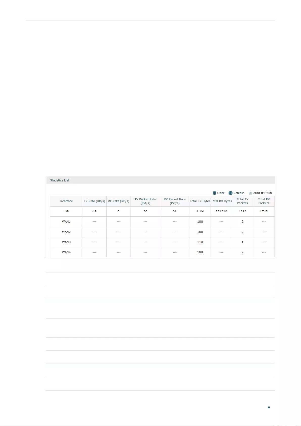
Choose the menu Status > Traffic Statistics > Interface Statistics to load the following page.
Figure 2-1 Interface Statistics
View the detailed traffic information of each interface in the statistics list.
TX Rate (KB/s) Displays the rate for transmitting data in kilobytes per second.
RX Rate (KB/s) Displays the rate for receiving data in kilobytes per second.
TX Packet Rate
(Pkt/s)
Displays the rate for transmitting data in packets per second.
RX Packet Rate
(Pkt/s)
Displays the rate for receiving data in packets per second.
Total TX Bytes Displays the bytes of packets transmitted on the interface.
Total RX Bytes Displays the bytes of packets received on the interface.
Total TX Packets Displays the number of packets transmitted on the interface.
Total RX Packets Displays the number of packets received on the interface.
Viewing Status Information Traffic Statistics
User Guide 9
You can enable Auto Refresh or click Refresh to get the latest statistics information, or
click Clear to clear the current statistics information.
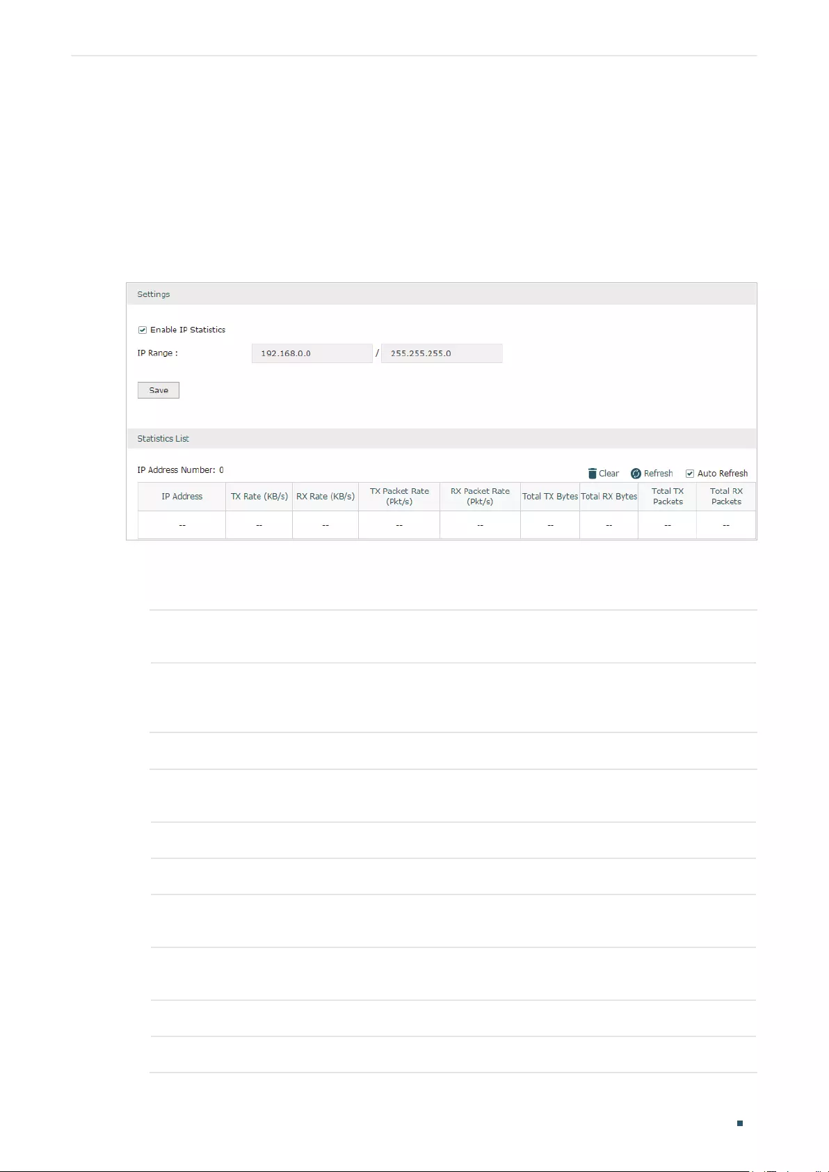
2.2 Viewing the IP Statistics
Choose the menu Status > Traffic Statistics > IP Statistics to load the following page.
Figure 2-2 IP Statistics
Follow these steps to view the traffic statistics of the specific IP addresses:
1) In the Settings section, enable IP Statistics and specify an IP range to monitor.
Enable IP
Statistics
Check the box to enable IP Statistics.
IP Range Specify an IP range. The router will monitor the packets whose source IP
addresses or destination IP addresses are in this range, and display the
statistics information in Statistics List.
2) In the Statistics List section, view the detailed traffic information of the IP addresses.
IP Address
Number
Displays the number of active users whose IP address is in the specified IP
range.
TX Rate (KB/s) Displays the rate for transmitting data in kilobytes per second.
RX Rate (KB/s) Displays the rate for receiving data in kilobytes per second.
TX Packet Rate
(Pkt/s)
Displays the rate for transmitting data in packets per second.
RX Packet Rate
(Pkt/s)
Displays the rate for receiving data in packets per second.
Total TX Bytes Displays the bytes of packets transmitted by the user who owns the IP address.
Total RX Bytes Displays the bytes of packets received by the user who owns the IP address.

User Guide 10
Viewing Status Information Traffic Statistics
Total TX Packets Displays the number of packets transmitted by the user who owns the IP
address.
Total RX Packets Displays the number of packets received by the user who owns the IP address.
You can enable Auto Refresh or click Refresh to get the latest statistics information, or
click Clear to clear the current statistics information.

Part 3
Configuring Network
CHAPTERS
1. Overview
2. WAN Configuration
3. LAN Configuration
4. IPTV Configuration
5. MAC Configuration
6. Switch Configuration
7. VLAN Configuration
8. IPv6 Configuration

User Guide 12
Configuring Network Overview
1 Overview
The Network module provides basic router functions, including WAN connection, DHCP
service, VLAN, IPTV service and more.
1.1 Supported Features
WAN
The router can provide a maximum of four WAN ports. Each WAN port has its own internet
connection, providing link backup and load balancing.
LAN
For LAN configuration, you can configure the LAN IP address and DHCP (Dynamic Host
Configuration Protocol) server. With its DHCP server enabled, the router can automatically
assign IP addresses to hosts in the LAN.
IPTV
IPTV services is based on the Internet protocol, rather than through traditional satellite
signal or cable transmission.
The router supports three kinds of IPTV configuration according to your ISP:
IPTV based on IGMP.
IPTV in Bridge mode.
IPTV in Custom mode.
MAC
You can change the default MAC address of the WAN port or LAN port according to your
needs.
Switch
The router supports some basic switch port management functions, like Port Mirror, Rate
Control, Flow Control and Port Negotiation, to help you to monitor the traffic and manage
the network effectively.
VLAN
The router supports 802.1Q VLAN, which can divide the LAN into multiple VLANs, helping
to manage the network more effectively.
IPv6
You can set up an IPv6 internet connection if your ISP provides IPv6 service.

Configuring Network WAN Configuration
User Guide 13
2 WAN Configuration
You can configure at most four WAN ports. Each WAN port can have its own WAN
connection, providing link backup and load balancing.
To complete WAN configuration, follow these steps:
1) Configure the number of WAN ports.
2) Configure the WAN connection.
2.1 Configuring the Number of WAN Ports
Choose the menu Network > WAN > WAN Mode to load the following page.
Figure 2-1 Configuring the WAN Mode
WAN Mode Specify the number of WAN ports.
1: Configure physical interface 1 as WAN1.
2: Configure physical interface 1 and interface 2 as WAN1 and WAN2 respectively.
3: Configure physical interface 1, interface 2 and interface3 as WAN1, WAN2 and
WAN3 respectively.
4: Configure physical interface 1, interface 2, interface 3 and interface 4 as WAN1,
WAN2, WAN3 and WAN4 respectively.
Note:
• When a WAN port is added, a port-related tab is automatically added; when a WAN port is de—
leted, the port-related tab is automatically deleted.
• The router will reboot after switching the WAN mode.
2.2 Configuring the WAN Connection
The router supports six connection types: Static IP, Dynamic IP, PPPoE, L2TP, PPTP and
BigPond Cable, you can choose one according to the service provided by your ISP.
User Guide 14
Configuring Network WAN Configuration
Static IP: If your ISP provides you with a fixed IP address and the corresponding
parameters, choose Static IP.
Dynamic IP: If your ISP automatically assigns the IP address and the corresponding
parameters, choose Dynamic IP.
PPPoE: If your ISP provides you with a PPPoE account, choose PPPoE.
L2TP: If your ISP provides you with an L2TP account, choose L2TP.
PPTP: If your ISP provides you with a PPTP account, choose PPTP.
BigPond Cable: If your ISP provides you with a BigPond Cable account, choose BigPond
Cable. BigPond Cable is only available for Australian users.
Configuring the Dynamic IP
Choose the menu Network > WAN > WAN to load the following page.
Figure 2-2 Configuring the Dynamic IP
In the Connection Configuration section, select the connection type as Dynamic IP. Enter
the corresponding parameters and click Save.
Connection Type Choose the connection type as Dynamic IP if your ISP automatically assigns the IP
address.
Host Name Optional. Enter a name for the router. It is null by default.
Upstream
Bandwidth
Specify the upstream bandwidth of the WAN port. The value configured here is the
upper limit of the “Maximum Upstream Bandwidth” on Transmission > Bandwidth
Control > Bandwidth Control page, to make “Bandwidth Control” take effect, please
ensure this parameter is set correctly.
Downstream
Bandwidth
Specify the downstream bandwidth of the WAN port. The value configured here is the
lower limit of the “Maximum Downstream Bandwidth” on Transmission > Bandwidth
Control > Bandwidth Control page, to make “Bandwidth Control” take effect, please
ensure this parameter is set correctly.

Configuring Network WAN Configuration
User Guide 15
MTU Specify the MTU (Maximum Transmission Unit) of the WAN port.
MTU is the maximum data unit transmitted in the physical network. When Dynamic
IP is selected, MTU can be set in the range of 576-1500 bytes. The default value is
1500.
Primary/
Secondary DNS
Optional. Enter the IP address of the DNS server provided by your ISP.
VLAN Add the WAN port to a VLAN. Generally, you don’t need to manually configure it
unless required by your ISP.
By default, the WAN port is automatically assigned to a VLAN, and the egress rule of
the VLAN is UNTAG, so the packets are transmitted by the WAN port without VLAN
tags. If you want the WAN port to transmit packets with VLAN tag, you need to create
the corresponding VLAN first and configure its egress rule as TAG, then manually
add the WAN port to that VLAN. To create VLANs, go to Network > VLAN > VLAN.
Note: When using the IPTV function, either in Bridge mode or Custom mode,
the router will automatically create corresponding VLANs after you finished the
configuration, and add port 1 (WAN 1) to the VLANs. Users cannot then manually
select the VLAN that WAN 1 belongs to.
Get IP using
Unicast DHCP
The broadcasting requirement may not be supported by a few ISPs. Select this
option if you can not get the IP address from your ISP even with a normal network
connection. This option is not required generally.
Connect/
Disconnect
Click the button to active/terminate the connection.
Configuring the Static IP
Choose the menu Network > WAN > WAN to load the following page.
Figure 2-3 Configuring the Static IP
In Connection Configuration section, select the connection type as Static IP. Enter the
corresponding parameters and click Save.

User Guide 16
Configuring Network WAN Configuration
Connection Type Choose the connection type as Static IP if your ISP has offered you a fixed IP
address.
IP Address Enter the IP address provided by your ISP.
Subnet Mask Enter the subnet mask provided by your ISP.
Default Gateway Enter the default gateway provided by your ISP.
Upstream
Bandwidth
Specify the downstream bandwidth of the WAN port. The value configured here is the
lower limit of the “Maximum Downstream Bandwidth” on Transmission > Bandwidth
Control > Bandwidth Control page, to make “Bandwidth Control” take effect, please
ensure this parameter is set correctly.
Downstream
Bandwidth
Specify the downstream bandwidth of the WAN port. The value configured here is the
lower limit of the “Maximum Downstream Bandwidth” on Transmission > Bandwidth
Control > Bandwidth Control page, to make “Bandwidth Control” take effect, please
ensure this parameter is set correctly.
MTU Specify the MTU (Maximum Transmission Unit) of the WAN port.
MTU is the maximum data unit transmitted in the physical network. When Static IP is
selected, MTU can be set in the range of 576-1500 bytes. The default value is 1500.
Primary/
Secondary DNS
Optional. Enter the IP address of the DNS server provided by your ISP.
VLAN Add the WAN port to a VLAN. Generally, you don’t need to manually configure it
unless required by your ISP.
By default, the WAN port is automatically assigned to a VLAN, and the egress rule of
the VLAN is UNTAG, so the packets are transmitted by the WAN port without VLAN
tags. If you want the WAN port to transmit packets with VLAN tag, you need to create
the corresponding VLAN first and configure its egress rule as TAG, then manually
add the WAN port to that VLAN. To create VLANs, go to Network > VLAN > VLAN.
Note: When using the IPTV function, either in Bridge mode or Custom mode,
the router will automatically create corresponding VLANs after you finished the
configuration, and add port 1 (WAN1) to the VLANs. Users cannot then manually
select the VLAN that WAN 1 belongs to.

Configuring Network WAN Configuration
User Guide 17
Configuring the PPPoE
Choose the menu Network > WAN > WAN to load the following page.
Figure 2-4 Configuring the PPPoE
In the Connection Configuration section, select the connection type as PPPoE. Enter the
corresponding parameters and click Save.
Connection Type Choose the connection type as PPPoE if your ISP provides you with a PPPoE
account.
Username Enter the PPPoE username provided by your ISP.
Password Enter the PPPoE password provided by your ISP.
Connection
Mode
Choose the connection mode, including Connect Automatically, Connect Manually
and Time-Based.
Connect Automatically: The router will activate the connection automatically when
the router reboots or the connection is down.
Connect Manually: You can manually activate or terminate the connection.
Time-Based: During the specified period, the router will automatically activate the
connection.
Time Choose the effective time range when the Connection Mode is chosen as Time-
Based. To create the time range, go to Preferences > Time Range > Time Range.
Upstream
Bandwidth
Specify the upstream bandwidth of the WAN port. The value configured here is the
upper limit of the “Maximum Upstream Bandwidth” on Transmission > Bandwidth
Control > Bandwidth Control page, to make “Bandwidth Control” take effect, please
ensure this parameter is set correctly.

User Guide 18
Configuring Network WAN Configuration
Downstream
Bandwidth
Specify the downstream bandwidth of the WAN port. The value configured here is the
lower limit of the “Maximum Downstream Bandwidth” on Transmission > Bandwidth
Control > Bandwidth Control page, to make “Bandwidth Control” take effect, please
ensure this parameter is set correctly.
MTU Specify the MTU (Maximum Transmission Unit) of the WAN port.
MTU is the maximum data unit transmitted in the physical network. When PPPoE is
selected, MTU can be set in the range of 576-1492 bytes. The default value is 1492.
Service Name Optional. Enter the service name. This parameter is not required unless provided by
your ISP. It is null by default.
Primary/
Secondary DNS
Optional. Enter the IP address of the DNS server provided by your ISP.
VLAN Add the WAN port to a VLAN. Generally, you don’t need to manually configure it
unless required by your ISP.
By default, the WAN port is automatically assigned to a VLAN, and the egress rule of
the VLAN is UNTAG, so the packets are transmitted by the WAN port without VLAN
tags. If you want the WAN port to transmit packets with VLAN tag, you need to create
the corresponding VLAN first and configure its egress rule as TAG, then manually
add the WAN port to that VLAN. To create VLANs, go to Network > VLAN > VLAN.
Note: When using the IPTV function, either in Bridge mode or Custom mode,
the router will automatically create corresponding VLANs after you finished the
configuration, and add port 1 (WAN 1) to the VLANs. Users cannot then manually
select the VLAN that WAN 1 belongs to.
Secondary
Connection
Secondary connection is required by some ISPs. Select the connection type required
by your ISP.
None: Select this if the secondary connection is not required by your ISP.
Dynamic IP: Select this if your ISP automatically assigns the IP address and subnet
mask for the secondary connection.
Static IP: Select this if your ISP provides you with a fixed IP address and subnet mask
for the secondary connection.
Connect/
Disconnect
Click the button to active/terminate the connection.

Configuring Network WAN Configuration
User Guide 19
Configuring the L2TP
Choose the menu Network > WAN > WAN to load the following page.
Figure 2-5 Configuring the L2TP
In the Connection Configuration section, select the connection type as L2TP. Enter the
corresponding parameters and click Save.
Connection Type Choose the connection type as L2TP if your ISP provides you with an L2TP account.
Username Enter the L2TP username provided by your ISP.
Password Enter the L2TP password provided by your ISP.
Connection
Mode
Choose the connection mode, including Connect Automatically, Connect Manually
and Time-Based.
Connect Automatically: The router will activate the connection automatically when
the router reboots or the connection is down.
Connect Manually: You can manually activate or terminate the connection.
Time-Based: During the specified period, the router will automatically activate the
connection.
Time Choose the effective time range when the Connection Mode is chosen as Time-
Based. To create the time range, go to Preferences > Time Range > Time Range.

User Guide 20
Configuring Network WAN Configuration
Upstream
Bandwidth
Specify the upstream bandwidth of the WAN port. The value configured here is the
upper limit of the “Maximum Upstream Bandwidth” on Transmission > Bandwidth
Control > Bandwidth Control page, to make “Bandwidth Control” take effect, please
ensure this parameter is set correctly.
Downstream
Bandwidth
Specify the downstream bandwidth of the WAN port. The value configured here is the
lower limit of the “Maximum Downstream Bandwidth” on Transmission > Bandwidth
Control > Bandwidth Control page, to make “Bandwidth Control” take effect, please
ensure this parameter is set correctly.
MTU Specify the MTU (Maximum Transmission Unit) of the WAN port.
MTU is the maximum data unit transmitted in the physical network. When L2TP is
selected, MTU can be set in the range of 576-1460 bytes. The default value is 1460.
Primary/
Secondary DNS
Optional. Enter the IP address of the DNS server provided by your ISP.
VLAN Add the WAN port to a VLAN. Generally, you don’t need to manually configure it
unless required by your ISP.
By default, the WAN port is automatically assigned to a VLAN, and the egress rule of
the VLAN is UNTAG, so the packets are transmitted by the WAN port without VLAN
tags. If you want the WAN port to transmit packets with VLAN tag, you need to create
the corresponding VLAN first and configure its egress rule as TAG, then manually
add the WAN port to that VLAN. To create VLANs, go to Network > VLAN > VLAN.
Note: When using the IPTV function, either in Bridge mode or Custom mode,
the router will automatically create corresponding VLANs after you finished the
configuration, and add port 1 (WAN 1) to the VLANs. Users cannot then manually
select the VLAN that WAN 1 belongs to.
Secondary
Connection
Select the secondary connection type provided by your ISP
The secondary connection is required for L2TP connection. The router will get
some necessary information after the secondary connection succeeded. These
information will be used in the L2TP connection process.
VPN Server/
Domain Name
Enter the VPN Server/Domain Name provided by your ISP.
IP Address Enter the IP address provided by your ISP for the secondary connection.
Subnet Mask Enter the subnet mask provided by your ISP for the secondary connection.
Default Gateway Enter the default gateway provided by your ISP for the secondary connection.
Primary/
Secondary DNS
Enter the primary/secondary DNS provided by your ISP for the secondary
connection.
Connect/
Disconnect
Click the button to active/terminate the connection.

Configuring Network WAN Configuration
User Guide 21
Configuring the PPTP
Choose the menu Network > WAN > WAN to load the following page.
Figure 2-6 Configuring the PPTP
In Connection Configuration section, select the connection type as PPTP. Enter the
corresponding parameters and click Save.
Connection Type Choose the connection type as PPTP if your ISP provides you with a PPTP account.
Username Enter the PPTP username provided by your ISP.
Password Enter the PPTP password provided by your ISP.
Connection
Mode
Choose the connection mode, including Connect Automatically, Connect Manually
and Time-Based.
Connect Automatically: The router will activate the connection automatically when
the router reboots or the connection is down.
Connect Manually: You can manually activate or terminate the connection.
Time-Based: During the specified period, the router will automatically activate the
connection.
Time Choose the effective time range when the Connection Mode is chosen as Time-
Based. To create the time range, go to Preferences > Time Range > Time Range.

User Guide 22
Configuring Network WAN Configuration
Upstream
Bandwidth
Specify the upstream bandwidth of the WAN port. The value configured here is the
upper limit of the “Maximum Upstream Bandwidth” on Transmission > Bandwidth
Control > Bandwidth Control page, to make “Bandwidth Control” take effect, please
ensure this parameter is set correctly.
Downstream
Bandwidth
Specify the downstream bandwidth of the WAN port. The value configured here is the
lower limit of the “Maximum Downstream Bandwidth” on Transmission > Bandwidth
Control > Bandwidth Control page, to make “Bandwidth Control” take effect, please
ensure this parameter is set correctly.
MTU Specify the MTU (Maximum Transmission Unit) of the WAN port.
MTU is the maximum data unit transmitted in the physical network. When PPTP is
selected, MTU can be set in the range of 576-1420 bytes. The default value is 1420.
Primary/
Secondary DNS
Optional. Enter the IP address of the DNS server provided by your ISP.
VLAN Add the WAN port to a VLAN. Generally, you don’t need to manually configure it
unless required by your ISP.
By default, the WAN port is automatically assigned to a VLAN by default, and the
egress rule of the VLAN is UNTAG, so the packets are transmitted by the WAN port
without VLAN tags. If you want the WAN port to transmit packets with VLAN tag, you
need to create the corresponding VLAN first and configure its egress rule as TAG,
then manually add the WAN port to that VLAN. To create VLANs, go to Network >
VLAN > VLAN.
Note: When using the IPTV function, either in Bridge mode or Custom mode,
the router will automatically create corresponding VLANs after you finished the
configuration, and add port 1 (WAN 1) to the VLANs. Users cannot then manually
select the VLAN that WAN 1 belongs to.
Secondary
Connection
Select the secondary connection type provided by your ISP
The secondary connection is required for PPTP connection. The router will get
some necessary information after the secondary connection succeeded. These
information will be used in the PPTP connection process.
VPN Server/
Domain Name
Enter the VPN Server/Domain Name provided by your ISP.
IP Address Enter the IP address provided by your ISP for the secondary connection.
Subnet Mask Enter the subnet mask provided by your ISP for the secondary connection.
Default Gateway Enter the default gateway provided by your ISP for the secondary connection.
Primary/
Secondary DNS
Enter the primary/secondary DNS provided by your ISP for the secondary
connection.
Connect/
Disconnect
Click the button to active/terminate the connection.
Configuring Network WAN Configuration
User Guide 23
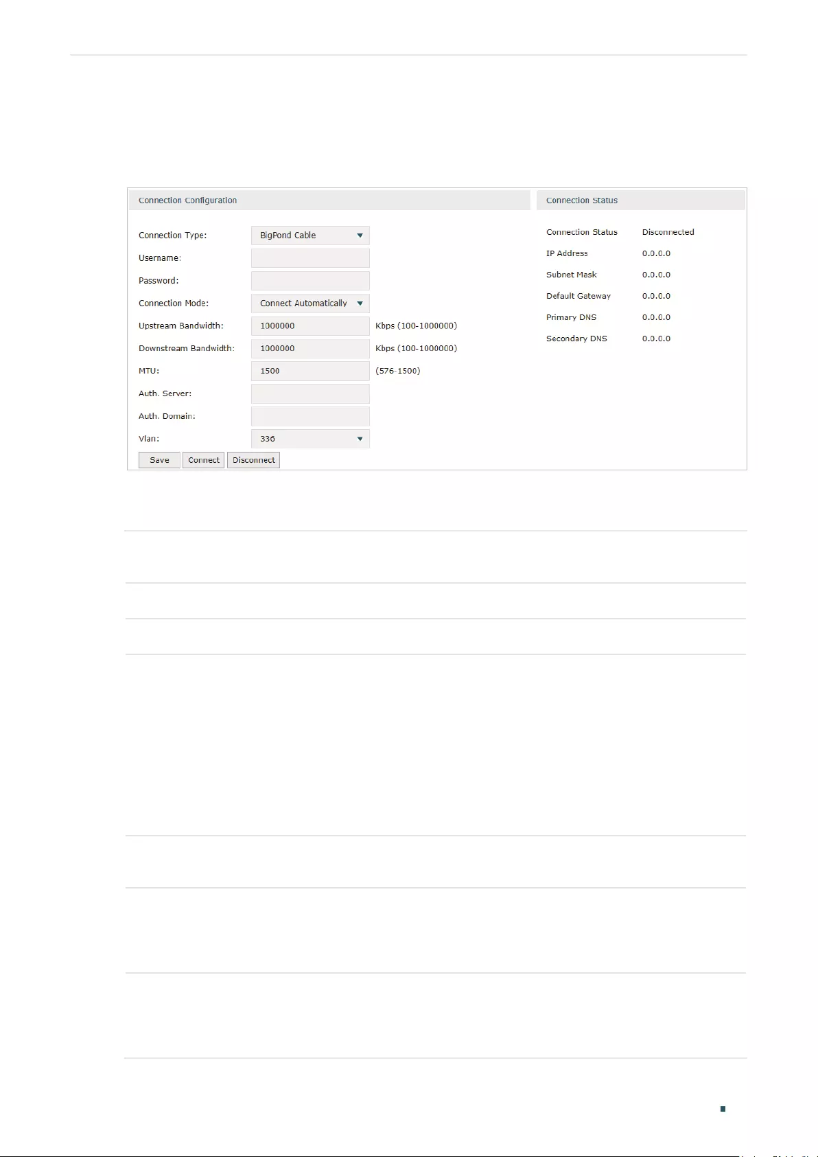
Configuring the BigPond Cable
Choose the menu Network > WAN > WAN to load the following page.
Figure 2-7 Configuring the BigPond Cable
In Connection Configuration section, select the connection type as BigPond Cable. Enter
the corresponding parameters and click Save.
Connection Type Choose the connection type as BigPond if your ISP provides you with a BigPond
account.
Username Enter the BigPond username provided by your ISP.
Password Enter the BigPond password provided by your ISP.
Connection
Mode
Choose the connection mode, including Connect Automatically, Connect Manually
and Time-Based.
Connect Automatically: The router will activate the connection automatically when
the router reboots or the connection is down.
Connect Manually: You can manually activate or terminate the connection.
Time-Based: During the specified period, the router will automatically activate the
connection.
Time Choose the effective time range when the Connection Mode is chosen as Time-
Based. To create the time range, go to Preferences > Time Range > Time Range.
Upstream
Bandwidth
Specify the upstream bandwidth of the WAN port. The value configured here is the
upper limit of the “Maximum Upstream Bandwidth” on Transmission > Bandwidth
Control > Bandwidth Control page, to make “Bandwidth Control” take effect, please
ensure this parameter is set correctly.
Downstream
Bandwidth
Specify the downstream bandwidth of the WAN port. The value configured here is the
lower limit of the “Maximum Downstream Bandwidth” on Transmission > Bandwidth
Control > Bandwidth Control page, to make “Bandwidth Control” take effect, please
ensure this parameter is set correctly.

User Guide 24
Configuring Network WAN Configuration
MTU Specify the MTU (Maximum Transmission Unit) of the WAN port.
MTU is the maximum data unit transmitted in the physical network. When BigPond
Cable is selected, MTU can be set in the range of 576-1500 bytes. The default value
is 1500.
Auth.Server Enter the authenticating server’s IP address or hostname.
Auth.Domain Enter the server’s domain name suffix (based on your location). For example, nsw.
bigpond.net.au for NSW/ACT, vic.bigpond.net.au for VIC/TAS/WA/SA/NT, or qld.
bigpond.net.au for QLD.
VLAN Add the WAN port to a VLAN. Generally, you don’t need to manually configure it
unless required by your ISP.
By default, the WAN port is automatically assigned to a VLAN, and the egress rule of
the VLAN is UNTAG, so the packets are transmitted by the WAN port without VLAN
tags. If you want the WAN port to transmit packets with VLAN tag, you need to create
the corresponding VLAN first and configure its egress rule as TAG, then manually
add the WAN port to that VLAN. To create VLANs, go to Network > VLAN > VLAN.
Note: When using the IPTV function, either in Bridge mode or Custom mode,
the router will automatically create corresponding VLANs after you finished the
configuration, and add port 1 (WAN 1) to the VLANs. Users cannot then manually
select the VLAN that WAN 1 belongs to.
Connect/
Disconnect
Click the button to active/terminate the connection.

Configuring Network LAN Configuration
User Guide 25
3 LAN Configuration
The LAN port is used to connect to the LAN clients, and works as the default gateway
for these clients. You can configure the DHCP server for the LAN clients, and clients will
automatically be assigned to IP addresses if the method of obtaining IP addresses is set as
“Obtain IP address automatically”.
For LAN configuration, you can:
Configure the IP address of the LAN port.
Configure the DHCP server.
3.1 Configuring the IP Address of the LAN Port
Choose the menu Network > LAN > LAN to load the following page.
Figure 3-1 Configuring the LAN IP Address
Enter the IP address of the LAN port, and click Save.
IP Address Enter the IP address of the LAN port.
This IP address is the default gateway of the LAN clients, and the IP addresses of all
the LAN clients should be in the same subnet with this LAN IP address.
Subnet Mask Enter the subnet mask of the LAN port.
Management
Vlan
Specify the management VLAN.
If you set a management VLAN here, then only the clients in the specified VLAN can
access and manage the router. The default value is “—“, which means no VLAN is
selected, and any client in the LAN can access and manage the router.

User Guide 26
Configuring Network LAN Configuration
Note:
• Changing the IP address of LAN port will automatically redirect the browser to the new man—
agement page. If the redirecting failed, please try to reconnect your PC to the router to auto-
matically get a new IP address, or configure a proper static IP address manually.
• Changing the IP address of the LAN port may affect some related functions, like the IP pool of
the DHCP server.
3.2 Configuring the DHCP Server
You can configure an IP address pool for the DHCP server to assign IP addresses. When
clients send requests to the DHCP server, the server will automatically assign IP addresses
and the corresponding parameters to the clients. Moreover, if you want to reserve an IP
address for a certain client, you can use Address Reservation to bind the IP address with
the client’s MAC address, and the bound IP address will always be assigned to that client.
Configuring the DHCP Server
Choose the menu Network > LAN > DHCP Server to load the following page.
Figure 3-2 Configuring the DHCP Server
Configure the parameters of the DHCP server, then click Save.

Configuring Network LAN Configuration
User Guide 27
Starting IP
Address
Enter the starting IP address of the DHCP server’s IP pool. The IP pool defines the IP
range that can be assigned to the clients in the LAN.
Note: The starting IP address should be in the same subnet with the IP address of the
LAN port.
Ending IP
Address
Enter the ending IP address of the DHCP server’s IP pool. The ending IP address
should be greater than the starting IP address.
Note: The ending IP address should be in the same subnet with the IP address of the
LAN port.
Lease Time Specify the lease time for DHCP clients.
Lease time defines how long the clients can use the IP address assigned by the DHCP
server. Generally, the client will automatically request the DHCP server for extending
the lease time before the lease expired. If the request failed, the client will have to stop
using that IP address when the lease finally expired, and try to get a new IP address
from the other DHCP servers.
Default Gateway Optional. It is recommended to enter the IP address of the LAN port.
Default Domain Optional. Enter the domain name of your network.
Primary/
Secondary DNS
Optional. Enter the DNS server address provided by your ISP. If you are not clear,
please consult your ISP.
Option 60 Optional. Specify the option 60 for device identification. Mostly it is used under the
scenario where the clients apply for different IP addresses from different servers
according to the needs. By default, it is TP-LINK.
If a client requests option 60, the server will respond a packet containing the option
60 configured here. And then the client will compare the received option 60 with its
own. If they are the same, the client will accept the IP address assigned by the server,
otherwise the assigned IP address will not be accepted.
Option 138 Optional. Specify the option 138, which can be configured as the management IP
address of an AC (Access Controller) device. If the APs in the local network request
this option, the server will respond a packet containing this option to inform the APs
of the AC’s IP address.
Status Check the box to enable the DHCP server.
Configuring the Address Reservation
Choose the menu Network > LAN > Address Reservation and click Add to load the
following page.

User Guide 28
Configuring Network LAN Configuration
Figure 3-3 Configuring the Address Reservation
Enter the MAC address of the client and the IP address to be reserved, then click OK.
MAC Address Enter the MAC address of the client.
IP Address Enter the IP address to be reserved.
Description Optional. Enter a brief description for the entry. Up to 32 characters can be entered.
Export to IP-
MAC Binding
Optional. Check the box to export this binding entry to IP-MAC Binding List on Firewall
> Anti ARP Spoofing > IP-MAC Binding page.
Status Check the box to enable this entry.
3.3 Viewing the DHCP Client List
Choose the menu Network > LAN > DHCP Client List to load the following page.
Figure 3-4 Viewing the DHCP Client List
Here you can view the DHCP client list.
Client Name Displays the name of the client.
MAC Address Displays the MAC address of the client.
Assigned IP
Address
Displays the IP address assigned to the client.
Lease Time Displays the remaining lease time of the assigned IP address. After the lease expires,
the IP address will be re-assigned.

Configuring Network IPTV Configuration
User Guide 29
4 IPTV Configuration
You can configure IPTV according to the type of IPTV service provided by your ISP:
Configure IPTV based on IGMP.
Configure IPTV in Bridge mode.
Configure IPTV in Custom mode.
4.1 Configuring IPTV Based on IGMP
Some ISPs provide IPTV service based on IGMP technology. In this scenario, you can just
enable IGMP snooping and IGMP proxy, and connect your STB (Set-Top Box) to any LAN
port of the router. The IPTV stream will then be transmitted to the corresponding LAN port.
Choose the menu Network > IPTV> IPTV to load the following page.
Figure 4-1 Configuring IPTV Based on IGMP
Enable IGMP Snooping and IGMP Proxy, and choose the IGMP version, then click Save.
IGMP Snooping Check the box to enable IGMP Snooping.
Without IGMP Snooping, the router will broadcast multicast stream to all LAN ports,
even though some LAN ports are not connected to any multicast member.
With IGMP Snooping enabled, the LAN ports listen IGMP packets transmitted between
the router and the clients and build a multicast table. The multicast table records the
multicast members and the corresponding connected LAN port. So the multicast
stream will be transmitted to only the ports that connected to multicast members.
IGMP Proxy Check the box to enable IGMP Proxy.
IGMP Proxy sends IGMP querier packets to the LAN ports to detect if there is any
multicast member connected to the LAN ports.
IGMP Version Choose the IGMP version as V2 or V3. The default is IGMP V2.
User Guide 30
Configuring Network IPTV Configuration
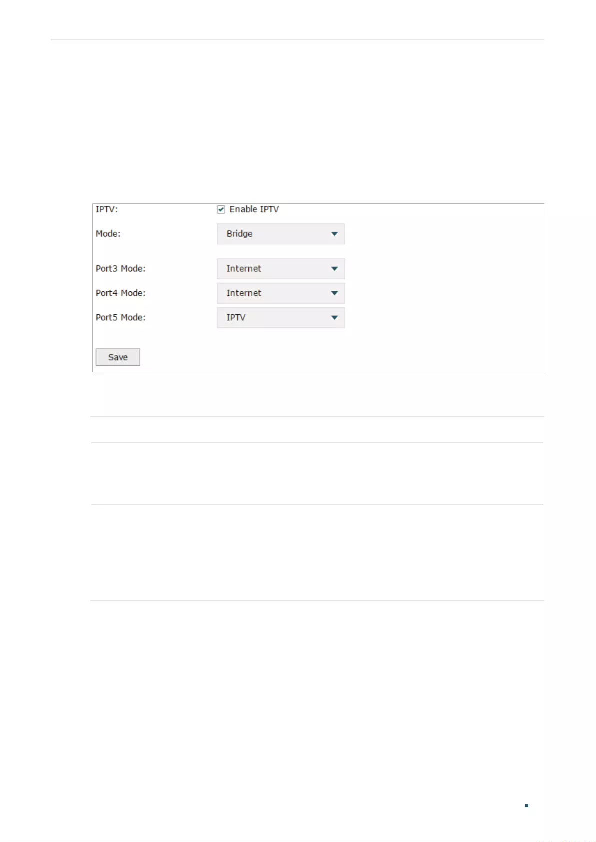
4.2 Configuring IPTV in Bridge Mode
If your ISP doesn’t provide any parameters and the IPTV service is not based on IGMP
technology, you can enable IPTV function and choose the Bridge mode, then specify a port
to connect IPTV set-top box.
Choose the menu Network > IPTV> IPTV to load the following page.
Figure 4-2 Configuring the Bridge Mode
Enable IPTV function, choose the mode as Bridge, and choose a LAN port to connect to the
IPTV set-top box, then click Save.
IPTV Check the box to enable IPTV function.
Mode Choose the mode as Bridge.
In Bridge mode, the LAN port chosen to connect to the IPTV becomes a dedicated
port for IPTV service.
Port Mode Specify the service to be supported by the LAN port.
Internet: Specify the port to support only internet service. If you want to access the
internet, you should connect your host to this port.
IPTV: Specify the port to only support IPTV service. If you want to use IPTV, you
should connnect your IPTV set-top box to this port.
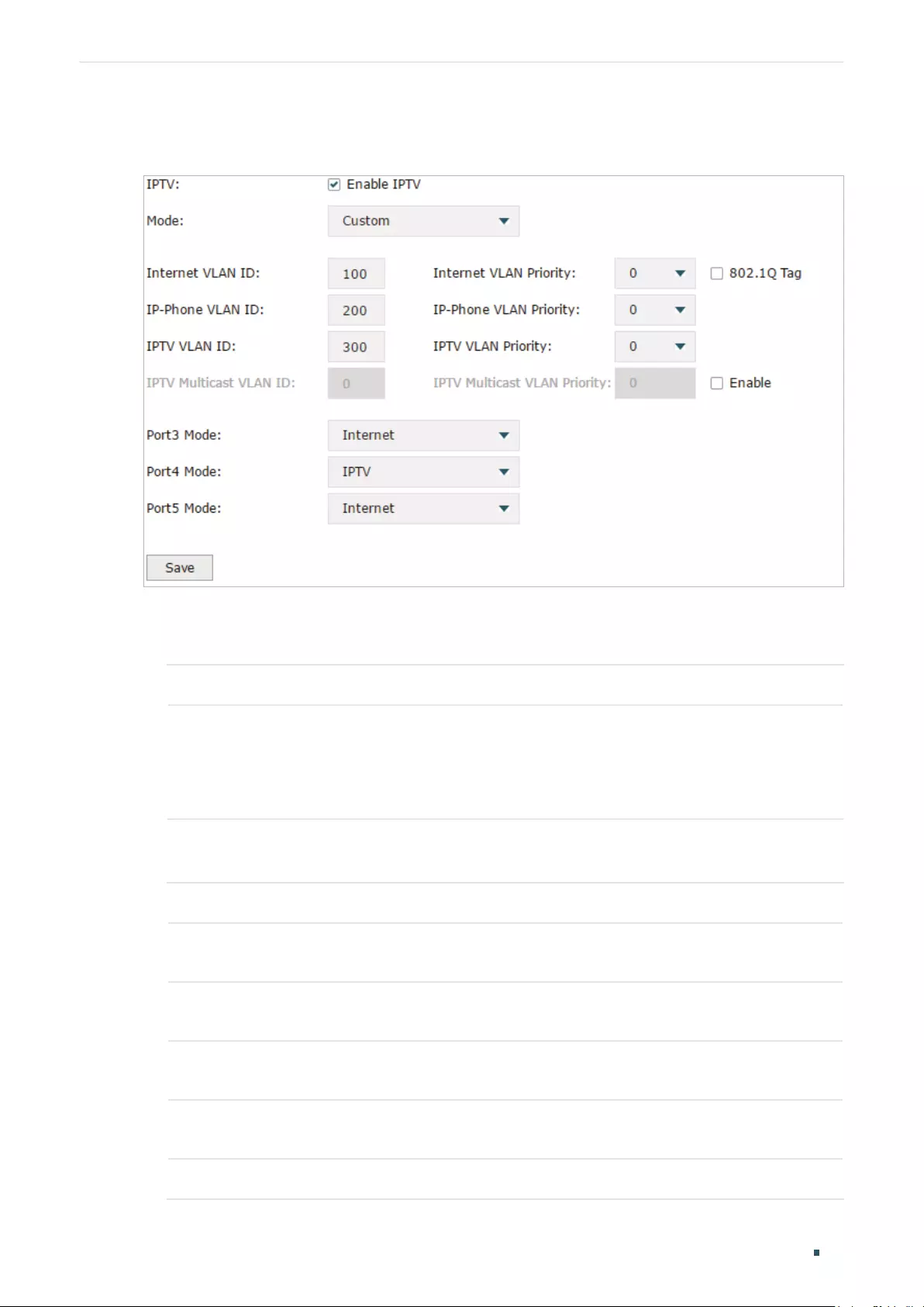
4.3 Configuring IPTV in Custom Mode
If your ISP supports Triple-Play service, i.e., providing internet, VoIP and IPTV services over
one single broadband connection, you can configure IPTV in Custom mode.
In Triple-Play, services are labeled with different VLAN tags specified by the ISP. When
the WAN port receives packets, it will forward the packets to the corresponding LAN port
according to the VLAN tag.
Configuring Network IPTV Configuration
User Guide 31
Choose the menu Network > IPTV> IPTV to load the following page.
Figure 4-3 Configuring the Custom Mode
Follow these steps to configure IPTV in Custom mode:
1) Enable IPTV function and choose the mode as Custom.
IPTV Check the box to enable IPTV function.
Mode Choose the mode as Custom.
In Custom mode, the services are labeled with different VLAN tags, which is
specified by the ISP. The WAN port will forward the packets to its corresponding
LAN port.
2) Enter the parameters provided by your ISP, including the VLAN IDs and priorities of
different services.
Internet VLAN ID Enter the VLAN ID of the internet service. It is provided by your ISP.
Internet VLAN
Priority
Enter the VLAN priority of the internet service. It is provided by your ISP.
802.1Q Tag Optional. Check the box and the egress internet packets of WAN 1 port will be
tagged.
IP-Phone VLAN
ID
Enter the VLAN ID of the IP-Phone service. It is provided by your ISP.
IP-Phone VLAN
Priority
Enter the VLAN priority of the IP-Phone service. It is provided by your ISP.
IPTV VLAN ID Enter the VLAN ID of the IPTV service. It is provided by your ISP.

User Guide 32
Configuring Network IPTV Configuration
IPTV VLAN
Priority
Enter the VLAN priority of the IPTV service. It is provided by your ISP.
IPTV Multicast
VLAN ID
Enter the VLAN ID of the IPTV multicast service. It is provided by your ISP.
IPTV Multicast
VLAN Priority
Enter the VLAN priority of the IPTV multicast service. It is provided by your ISP.
3) Specify the service to support for the LAN port.
Port Mode Specify the service to be supported by the LAN port.
Internet: Specify the port to support only Internet service. If you want to surf the
internet, you should connect your host to this port.
IP-Phone: Specify the port to support only IP-Phone service. If you want to make
an IP-Phone call, you should connect your IP-Phone to this port.
IPTV: Specify the port to only support IPTV service. If you want to use IPTV, you
should connnect your IPTV set-top box to this port.
Note:
• Among the WAN ports, only WAN 1 supports IPTV service. So if you want to use IPTV function,
connect your ISP network to WAN 1.
• In Bridge mode, after you have saved the configuration, the router will automatically and ran—
domly create some VLANs for WAN 1 and the LAN ports. These VLANs will be displayed on the
VLAN page.
• In Custom mode, after you configured the VLAN IDs of different services, these VLANs will
automatically be created, and port 1 (WAN 1) will automatically be added to the IPTV VLAN and
Internet VLAN. These VLANs will be displayed on the VLAN page.
Configuring Network MAC Configuration
User Guide 33
5 MAC Configuration
Generally, the MAC address does not need to be changed. However, in some particular
situations, you may need to change the MAC address of the WAN port or LAN port.
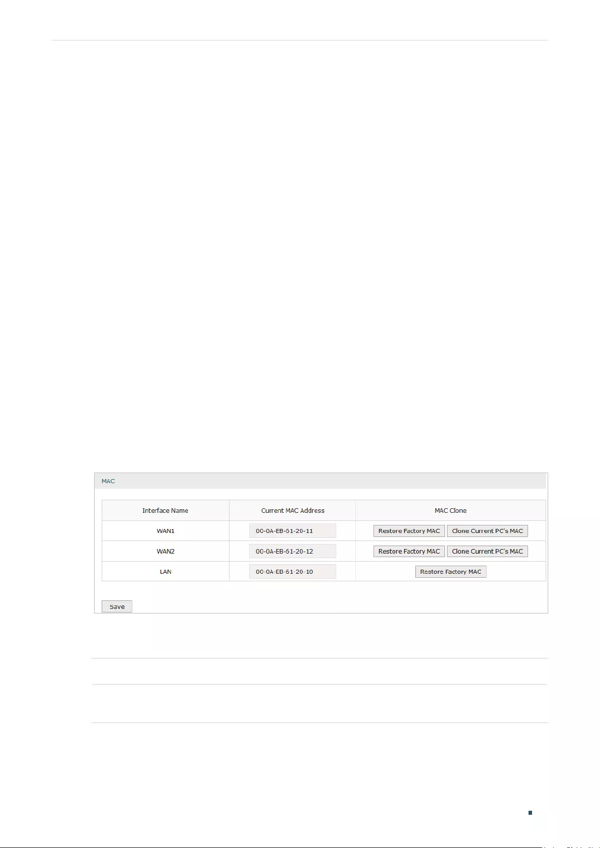
Configure the MAC Address of the WAN port
In the condition that your ISP has bound the account to the MAC address of the dial-up
device, if you want to replace the dial-up device with this router, you can just set the MAC
address of this router’s WAN port as the same as that of the previous dial-up device for a
normal internet connection.
Configure the MAC Address of the LAN port
In a complex network with all the devices are ARP bound , if you want to replace the current
router with this router, you can just set the MAC address of this router’s LAN port as the
same as that of the previous router, which can avoid all the devices under this network
node to update their ARP binding tables.
5.1 Configuring MAC Address
Choose the menu Network > MAC > MAC to load the following page.
Figure 5-1 Configuring MAC Address
Configure the MAC address of the WAN port or LAN port according to your need, then click
Save.
Interface Name Displays the WAN port and LAN port.
Current MAC
Address
Configure the MAC address of the WAN port or LAN port.

User Guide 34
Configuring Network MAC Configuration
MAC Clone Restore Factory MAC: Click this button to restore the MAC address to the factory
default value.
Clone Current PC’s MAC: Click this button to clone the MAC address of the PC you
are currently using to configure the router. It’s only available for the WAN ports.
Note:
To avoid a MAC address conflict in the LAN, it is not permitted to set the MAC address of the router’s
LAN port as the MAC address of the current management PC.

Configuring Network Switch Configuration
User Guide 35
6 Switch Configuration
The router provides some basic switch port management function, including Statistics,
Port Mirror, Port Config and Port Status.
6.1 Viewing the Statistics
Choose the menu Network > Switch > Statistics to load the following page.
Figure 6-1 Viewing the Statistics
Statistics displays the detailed traffic information of each port, which allows you to monitor
the traffic and locate faults promptly.
Unicast Displays the number of normal unicast packets received or transmitted on the port.
Broadcast Displays the number of normal broadcast packets received or transmitted on the port.
Pause Displays the number of flow control frames received or transmitted on the port.
Multicast Displays the number of normal multicast packets received or transmitted on the port.

User Guide 36
Configuring Network Switch Configuration
Total Displays the total bytes of the received or transmitted packets (including error
frames).
Undersize Displays the number of received packets which have a length less than 64 bytes
(including error frames).
Normal Displays the number of received packets which have length between 64 bytes and the
maximum frame length (including error frames).
Oversize Displays the number of received packets that have a length greater than the maximum
frame length (including error frames).
Note:
Error Frame: The frames that have a false checksum.
Maximum frame length: The maximum frame length supported by the router. For untagged frames,
it’s 1518 bytes long; for tagged packets, it’s 1522 bytes long.
6.2 Configuring Port Mirror
Port Mirror function allows the switch to forward packet copies of the monitored port(s) to
a specific monitoring port. Then you can analyze the copied packets to monitor network
traffic and troubleshoot network problems.
Choose the menu Network > Switch > Mirror to load the following page.
Figure 6-2 Configuring Port Mirror
Follow these steps to configure Port Mirror:
1) In Settings section, enable Port Mirror function, and choose the mirror mode.

Configuring Network Switch Configuration
User Guide 37
Enable Port
Mirror
Check the box to enable Port Mirror function.
Mirror Mode Choose the mirror mode which includes Ingress, Egress and Ingress and Egress.
Ingress: The packets received by the mirrored port will be copied to the mirroring
port.
Egress: The packets sent by the mirrored port will be copied to the mirroring port.
Ingress and Egress: Both the incoming and outgoing packets through the
mirrored port will be copied to the mirroring port.
2) In the Monitor List section, set the mirroring port and the mirrored port(s), then click
Save.
Mirroring Port The packets through the mirrored port will be copied to this port.
Usually, the mirroring port is connected to a data diagnose device, which is used
to analyze the mirrored packets for monitoring and troubleshooting the network.
Mirrored Port The packets through this port will be copied to the mirroring port.
Usually, the mirrored ports are the ports to be monitored.
6.3 Configuring Rate Control
Rate Control enables you to control the traffic rate for the specific packets on each port to
manage your network.
Choose the menu Network > Switch > Rate Control to load the following page.
Figure 6-3 Configuring Rate Control
Choose the port and configure the ingress frames or egress frames limitation, then click
Save.
Ingress Limit Check the box to enable the Ingress Limit feature.
User Guide 38
Configuring Network Switch Configuration
Ingress Frame
Type
Specify the ingress frame type to be limited. It is All Frames by default.
All Frames: The ingress rate of all frames is limited.
Broadcast: The ingress rate of broadcast frames is limited.
Broadcast and Multicast: The ingress rate of broadcast and multicast frames is
limited.
Ingress Rate
(Mbps)
Specify the limit rate for the ingress packets.
Egress Limit Check the box to enable Egress Limit feature.
Egress Rate
(Mbps)
Specify the limit rate for the egress packets.
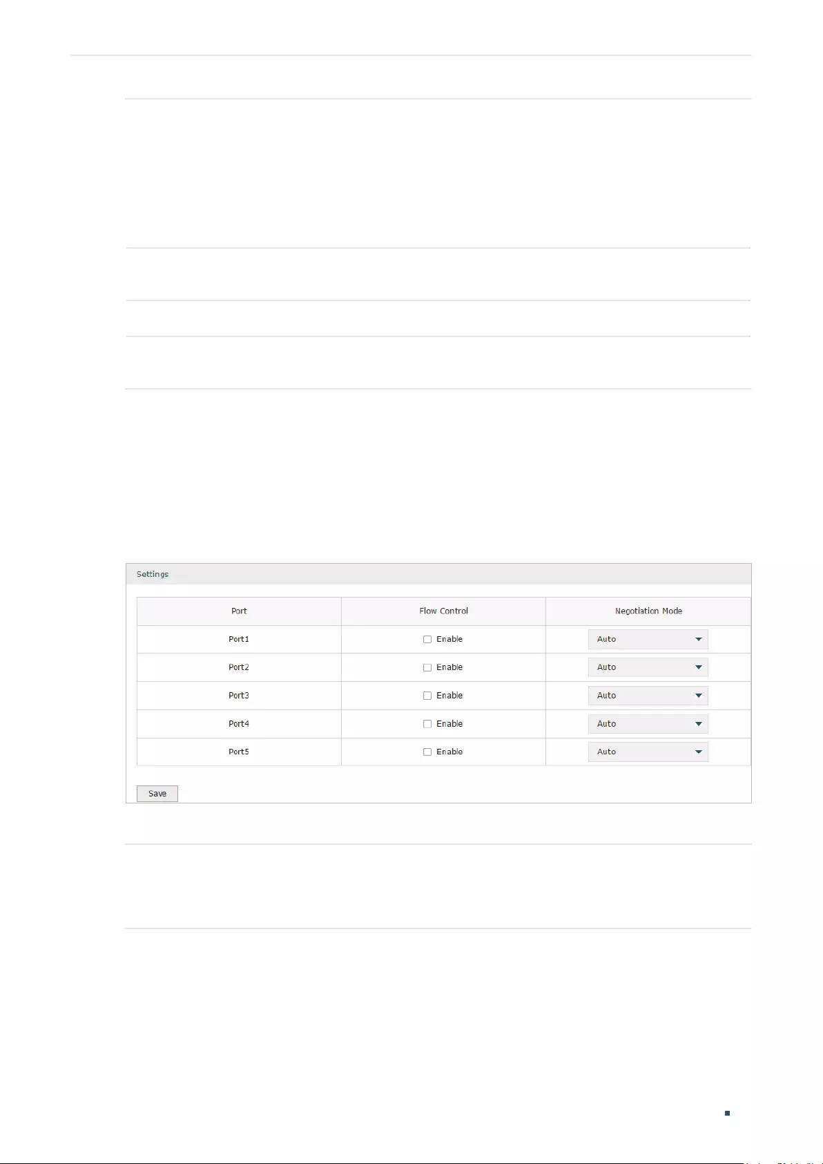
6.4 Configuring Port Config
You can configure the flow control and negotiation mode for the port.
Choose the menu Network > Switch > Port Config to load the following page.
Figure 6-4 Configuring Flow Control and Negotiation
Configure the flow control and negotiation mode for a port.
Flow Control Check the box to enable the flow control function.
Flow Control is the process of managing the data transmission of the sender to avoid
the receiver getting overloaded.
Configuring Network Switch Configuration
User Guide 39
Negotiation
Mode
Select the negotiation mode for the port. You can set the mode as Auto, or manually
set the speed and duplex mode for the port. It is recommended to configure both
devices of a link to work in Auto-Negotiation mode or manually configure them to work
in the same speed and duplex mode.
If the two devices at both sides work in Auto mode, they will advertise their speed and
duplex abilities to each other, and negotiate the optimal speed and duplex mode.
If the local device works in Auto mode while the peer device does not, the local device
will automatically detect and match the speed with the peer device. The local device
will work in half-duplex mode, no matter what duplex mode the peer device is in.
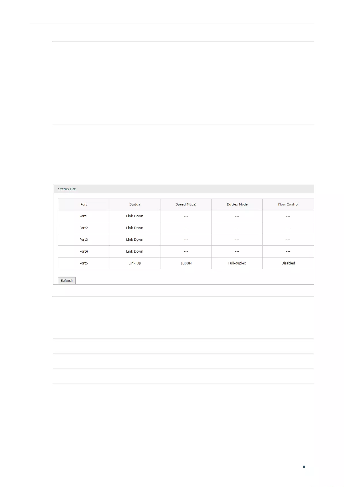
6.5 Viewing Port Status
Choose the menu Network > Switch > Port Status to load the following page.
Figure 6-5 Viewing Port Status
Status Displays the port status.
Link Down: The port is not connected.
Link Up: The port is working normally.
Speed (Mbps) Displays the port speed.
Duplex Mode Displays the duplex mode of the port.
Flow Control Displays if the Flow Control is enabled.

User Guide 40
Configuring Network VLAN Configuration
7 VLAN Configuration
The router supports 802.1Q VLAN, which can divide a LAN into multiple logical LANs.
Each logical LAN is a VLAN. Hosts in the same VLAN can communicate with each other.
However, hosts in different VLANs cannot communicate directly. Therefore, broadcast
packets can be limited to within the VLAN.
7.1 Creating a VLAN
Choose the menu Network > VLAN > VLAN to load the following page.
Figure 7-1 Creating a VLAN
Create a VLAN and add the port(s) to the VLAN, then click OK.
VLAN ID Enter a VLAN ID. The value ranges from 1 to 4094.
Name Specify the name of the VLAN for easy identification.
Ports Check the box to select the port and specify the port type in the specified VLAN. The
port can be divided into two types: TAG or UNTAG.
TAG: The egress rule of the packets transmitted by the port is Tagged.
UNTAG: The egress rule of the packets transmitted by the port is Untagged.
Description Optional. Enter a brief description for easy management and searching.
Configuring Network VLAN Configuration
User Guide 41
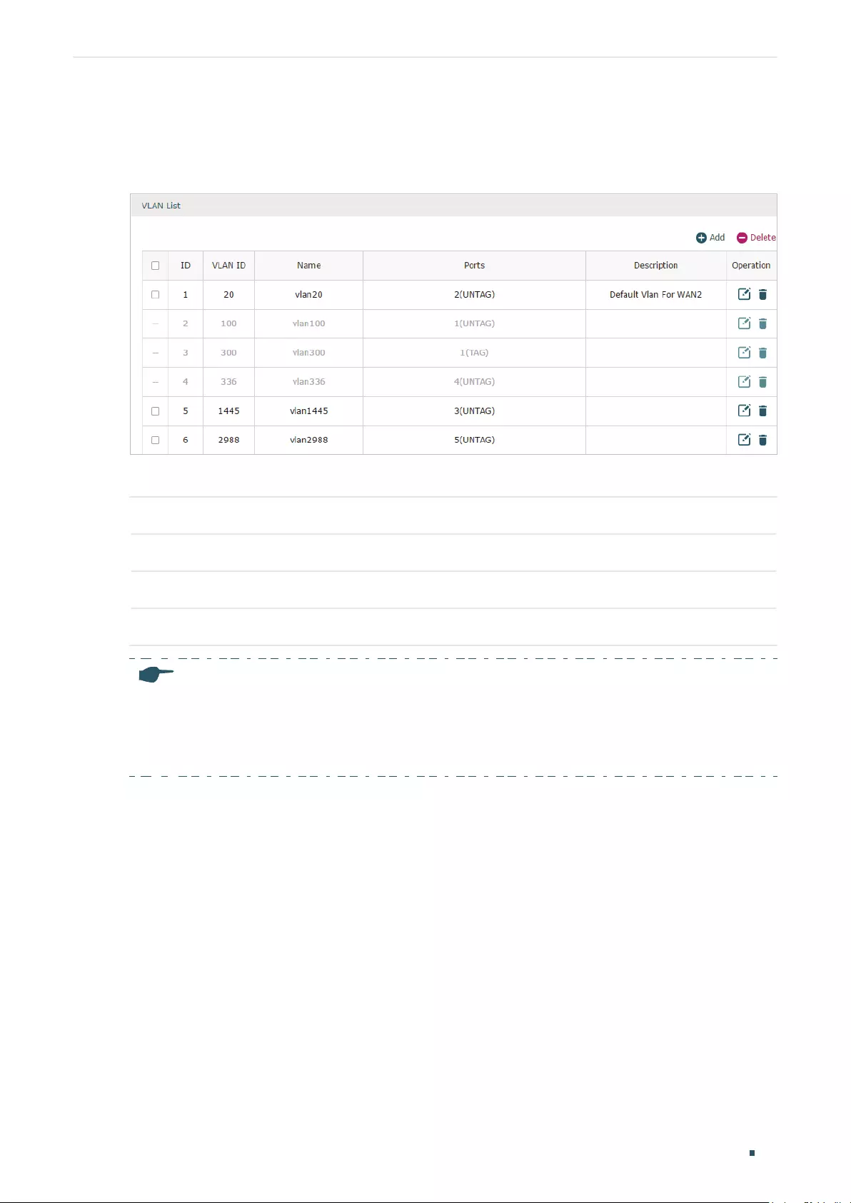
Viewing the VLANs
Choose the menu Network > VLAN > VLAN to load the following page.
Figure 7-2 Viewing the VLAN
In the VLAN list you can view all the VLANs existing in the router.
VLAN ID Displays the VLAN ID.
Name Displays the VLAN name.
Ports Displays the ports which belongs to the corresponding VLAN.
Description Displays the description of the VLAN.
Note:
The VLAN list contains all the VLANs existing in the router. Some of them are manually created by
the user, and can be edited or deleted. Some are automatically created and referenced by the router
for some special scenarios like IPTV or management VLAN, and you cannot edit or delete these
VLANs.

User Guide 42
Configuring Network VLAN Configuration
7.2 Configuring the PVID of a Port
Choose the menu Network > VLAN > Port to load the following page.
Figure 7-3 Configuring the PVID
Configure the PVID of the port, then click Save.
Port Displays the port.
PVID Specify the PVID for the port. PVID indicates the default VLAN for the corresponding
port.
VLAN Displays the VLAN(s) the port belongs to.
Configuring Network IPv6 Configuration
User Guide 43
8 IPv6 Configuration
To complete IPv6 configuration, follow these steps:
1) Configure the LAN to specify the type of assigning IPv6 address to the client.
2) Configure the WAN connection.
8.1 Configuring the LAN
Configure the type of assigning IPv6 address to the LAN clients.
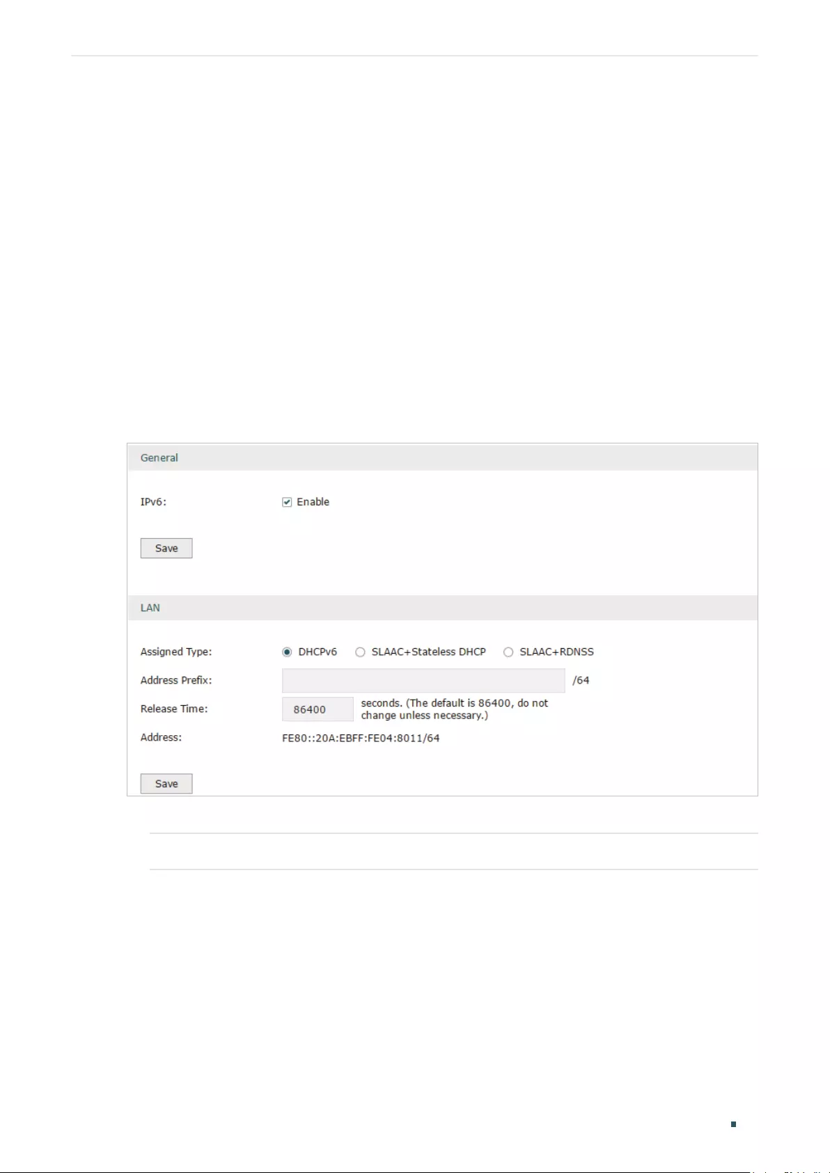
Choose the menu Network > IPv6 > LAN to load the following page.
Figure 8-1 Configuring the LAN
1) In Global section, enable IPv6 function and click Save.
IPv6 Check the box to enable IPv6 function for the LAN.
2) In LAN section, configure the Assigned Type and Address prefix, then click Save.

User Guide 44
Configuring Network IPv6 Configuration
Assigned Type Select the appropriate type of assigning the IPv6 address according to your ISP.
DHCPv6: The DHCP server automatically assigns the IPv6 address and DNS
information to the clients.
SLAAC+Stateless DHCP: The DHCP server advertises the IPv6 prefix to the
client, the client then dynamically form a host identifier that is 64 bits long and will
be suffixed to the end of the advertised prefix to form an IPv6 address. Generally,
the host identifier was formed using the EUI-64. The DHCP server can also offer
the DNS information to the client when the client requests.
SLAAC+RDNSS: The DHCP server advertises the IPv6 prefix to the client, the
client then dynamically form a host identifier that is 64 bits long and will be
suffixed to the end of the advertised prefix to form an IPv6 address. Generally,
the host identifier was formed using the EUI-64. The DHCP server will also
automatically advertise the DNS information to the client.
Address Prefix Enter the LAN address prefix provided by your ISP.
Note: If the “Prefix Delegation” in WAN configuration is enabled, the LAN prefix will
be automatically assigned by the ISP, and you do not need to manually configure
it here.
Release Time The duration time in seconds when the assigned IPv6 address remains valid when
you choose the Assigned Type as DHCPv6. The default value is 86400 seconds .
Address Displays the IPv6 address of the LAN port.
8.2 Configuring the WAN
You can configure at most four WAN ports. Each WAN port can have its own IPv6 WAN
connection, providing link backup and expanding the bandwidth.
To complete WAN configuration, follow these steps:
1) Configure the number of WAN ports.
2) Configure the WAN connection.
8.2.1 Configuring the Number of WAN Ports
Choose the menu Network > WAN > WAN Mode to load the following page.
Figure 8-2 Configuring the WAN Mode

Configuring Network IPv6 Configuration
User Guide 45
WAN Mode Specify the number of WAN ports.
1: Configure physical interface 1 as WAN1.
2: Configure physical interface 1 and interface 2 as WAN1 and WAN2 respectively.
3: Configure physical interface 1, interface 2 and interface3 as WAN1, WAN2 and
WAN3 respectively.
4: Configure physical interface 1, interface 2, interface 3 and interface 4 as WAN1,
WAN2, WAN3 and WAN4 respectively.
Note:
• When a WAN port is added, the port-related entries are automatically added; when a WAN port
is deleted, the port-related entries are automatically deleted.
• The router will reboot after switching the WAN mode.
8.2.2 Configuring the WAN Connection
The router supports five IPv6 connection types: Static IP, Dynamic IP (SLAAC/DHCPv6),
PPPoE, 6to4 Tunnel and Pass-Through (Bridge), you can choose one according to the
information provided by your ISP.
Static IP: Select this if your ISP provides you with a fixed IPv6 address, default gateway and
DNS address.
Dynamic IP (SLAAC/DHCPv6): Select this if your ISP automatically assigns the IPv6
address and the corresponding parameters.
PPPoE: Select this if your ISP provides you with a PPPoE account.
6to4 Tunnel: Select this if your ISP uses 6to4 deployment for assigning address.
Pass-Through (Bridge): Select this if your ISP uses Pass-Through (Bridge) network
deployment. No parameters are required for this type of connection.
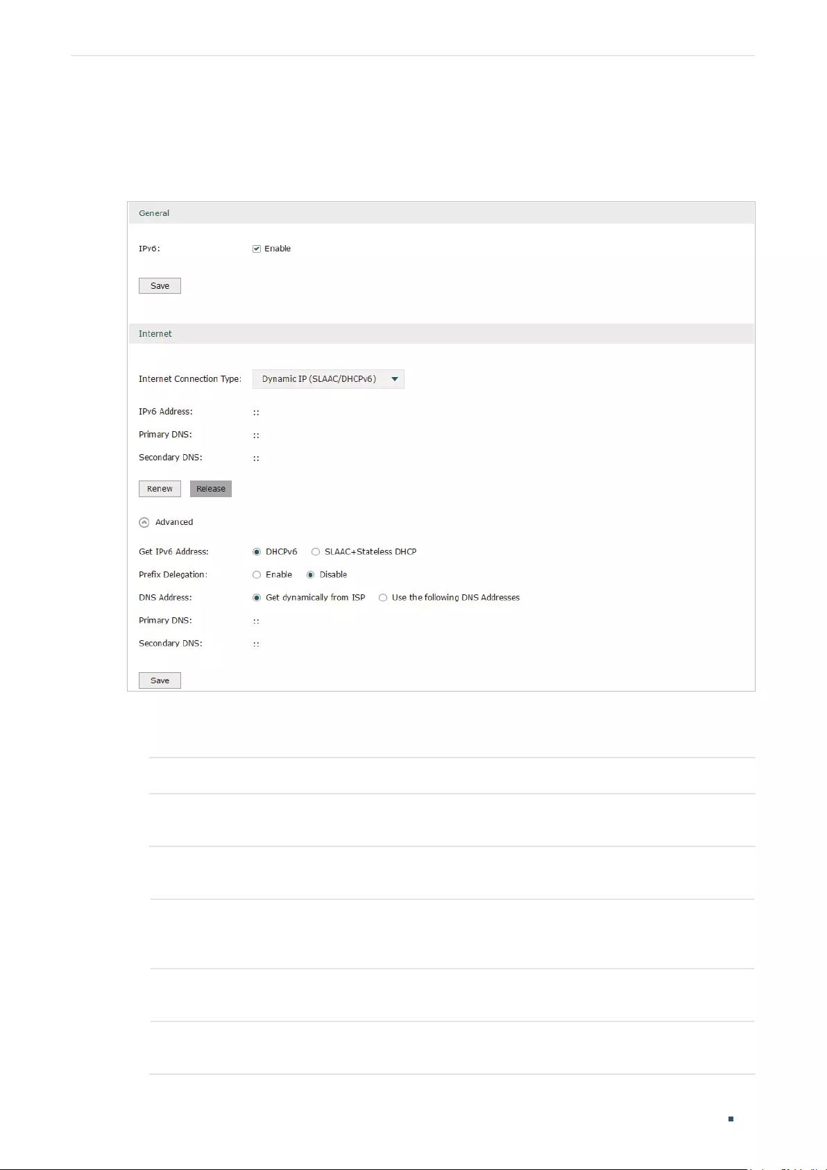
User Guide 46
Configuring Network IPv6 Configuration
Choose the menu Network > IPv6 > WAN to load the following page.
Configuring the Dynamic IP (SLAAC/DHCPv6)
Figure 8-3 Configuring the Dynamic IP (SLAAC/DHCPv6)
Follow these steps to configure Dynamic IP connection:
1) In the General section, check the box to enable IPv6 function, then click Save.
IPv6 Check the box to enable IPv6 function.
2) In the Internet section, choose the Internet Connection type as Dynamic IP (SLAAC/
DHCPv6), and configure the corresponding parameters. Then click Save.
Internet
Connection Type
Choose Dynamic IP (SLAAC/DHCPv6) as the connection type.
IPv6 Address/
Primary DNS/
Secondary DNS
Displays the IPv6 address/Primary DNS/Secondary DNS of the WAN port. These
parameters are automatically assigned by the DHCPv6 server from your ISP.
Renew Click this button to get new IPv6 parameters assigned by the DHCPv6 server
from the ISP.
Release Click this button to release the IPv6 parameters assigned by DHCPv6 server
from the ISP.
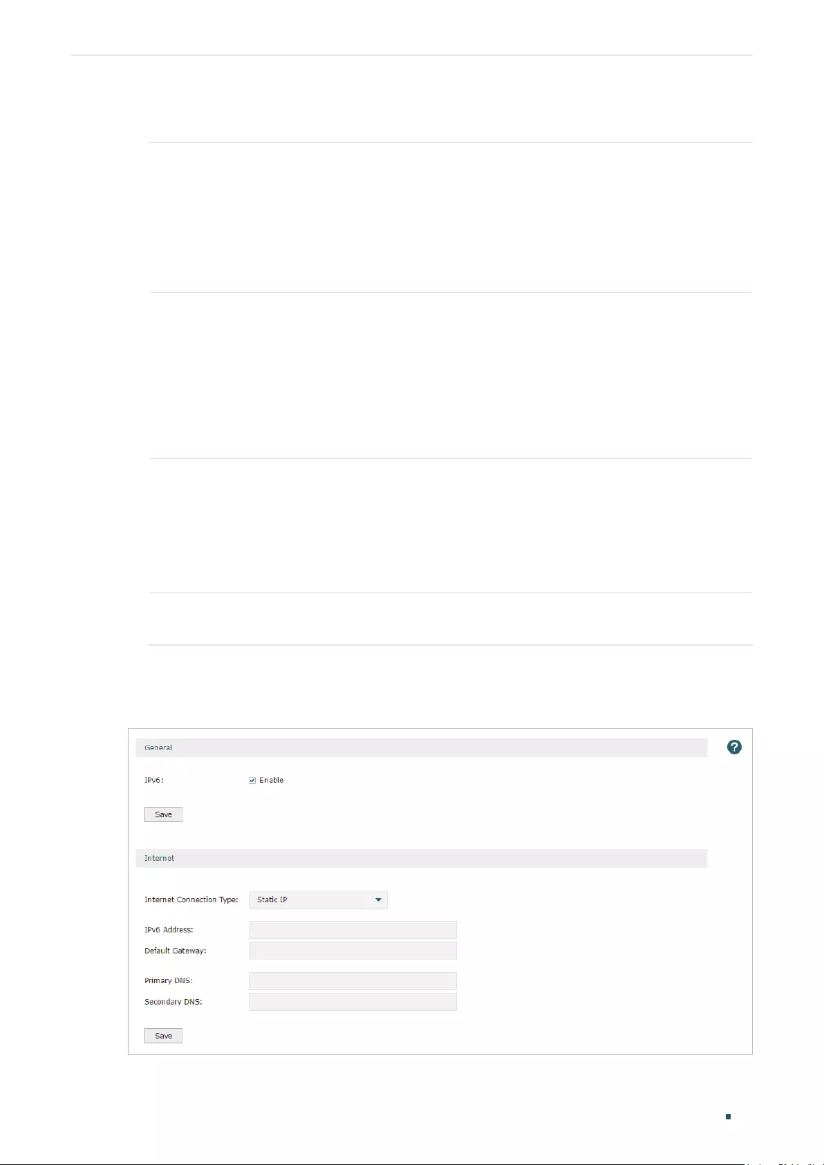
Configuring Network IPv6 Configuration
User Guide 47
3) In the Internet section, click Advanced to configure the way of getting the IPv6 address
and DNS address, and configure the Prefix Delegation. Then click Save.
Get IPv6 Address Choose the method by which the IPv6 address is obtained from the ISP.
DHCPv6: The DHCP server automatically assigns the IPv6 address.
SLAAC+Stateless DHCP: The DHCP server advertises the IPv6 prefix to the
WAN port, the WAN port then dynamically form a host identifier that is 64 bits
long and will be suffixed to the end of the advertised prefix to form an IPv6
address. Generally, the host identifier was formed using the EUI-64.
Prefix Delegation Enable or disable prefix delegation. The prefix will be assigned to the LAN clients.
Enable: The prefix of the IPv6 address will automatically be assigned by the ISP,
and you do not need to configure the prefix in LAN page.
Disable: You need to enter a prefix manually.
Note: If more than one WAN port is enabled with Prefix Delegation, the LAN port
will assign the prefix of the latest enabled WAN port to the LAN clients.
DNS Address Choose the way of getting DNS address from the ISP.
Get dynamically from ISP: The DNS address will automatically assigned by the
ISP.
Use the following DNS address: The user need to manually enter the DNS
address provided by the ISP.
Primary DNS/
Secondary DNS
Enter the DNS address provided by the ISP.
Configuring the Static IP
Figure 8-4 Configuring the Static IP

User Guide 48
Configuring Network IPv6 Configuration
Follow these steps to configure static IP connection:
1) In the General section, check the box to enable IPv6 function, then click Save.
IPv6 Check the box to enable IPv6 function.
2) In the Internet section, choose the Internet Connection type as Static IP, and configure
the corresponding parameters. Then click Save.
Internet
Connection Type
Choose Static IP as the connection type.
IPv6 Address Enter the IPv6 address provided by your ISP.
Default Gateway Enter the default gateway provided by your ISP.
Primary DNS/
Secondary DNS
Enter the DNS address provided by your ISP.
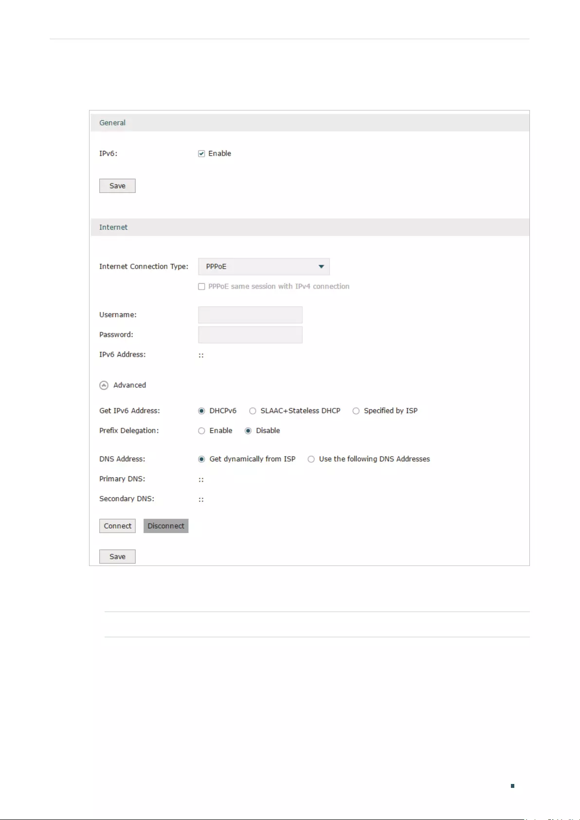
Configuring Network IPv6 Configuration
User Guide 49
Configuring the PPPoE
Figure 8-5 Configuring the PPPoE
Follow these steps to configure PPPoE connection:
1) In the General section, check the box to enable IPv6 function, then click Save.
IPv6 Check the box to enable IPv6 function.
2) In the Internet section, choose the Internet Connection type as PPPoE, and configure
the corresponding parameters. Then click Save.

User Guide 50
Configuring Network IPv6 Configuration
Internet
Connection Type
Choose PPPoE as the connection type.
Note:
• If your ISP provides only one PPPoE account for both IPv4 and IPv6 con—
nections, and you have already established an IPv4 connection on this WAN
port, you can check PPPoE same session with IPv4 connection, then the
WAN port will use the PPP session of IPv4 PPPoE connection to get the IPv6
address. In this case, you do not need to enter the username and password
of the PPPoE account on this page.
• If your ISP provides two separate PPPoE accounts for the IPv4 and IPv6
connections, or the IPv4 connection of this WAN port is not based on PP—
PoE, please don’t check PPPoE same session with IPv4 connection and
manually enter the username and password for the IPv6 connection.
Username Enter the PPPoE username provided by your ISP.
Password Enter the PPPoE password provided by your ISP.
IPv6 Address Displays the IPv6 address of the WAN port.
3) In the Internet section, click Advanced to configure the way of getting the IPv6 address
and DNS address, and configure the Prefix Delegation. Then click Save.
Get IPv6 Address Choose the method by which the IPv6 address is obtained from the ISP.
DHCPv6: The DHCP server automatically assigns the IPv6 address.
SLAAC+Stateless DHCP: The DHCP server advertises the IPv6 prefix to the
WAN port, the WAN port then dynamically forms a host identifier that is 64
bits long and will be suffixed to the end of the advertised prefix to form an IPv6
address. Generally, the host identifier is formed using the EUI-64.
Prefix Delegation Enable or disable prefix delegation. The prefix will be assigned to the LAN clients.
Enable: The prefix of the IPv6 address will automatically be assigned by the ISP,
and you do not need to configure the prefix in the LAN page.
Disable: You need to enter a prefix manually.
Note: If more than one WAN port is enabled with Prefix Delegation, the LAN port
will assign the prefix of the latest enabled WAN port to the LAN clients.
DNS Address Choose the way of getting DNS address from the ISP.
Get dynamically from ISP: The DNS address will automatically assigned by the
ISP.
Use the following DNS address: The user needs to manually enter the DNS
address provided by the ISP.
Primary DNS/
Secondary DNS
Enter the DNS address provided by the ISP.

Configuring Network IPv6 Configuration
User Guide 51
Configuring the 6to4 Tunnel
6to4 is an internet transition mechanism for migrating from IPv4 to IPv6, a system that
allows IPv6 packets to be transmitted over an IPv4 network. The IPv6 packet will be
encapsulated in the IPv4 packet and transmitted to the IPv6 destination through IPv4
network.
Figure 8-6 Configuring the 6to4 Tunnel
Follow these steps to configure 6to4 Tunnel connection:
1) In the General section, check the box to enable IPv6 function, then click Save.
IPv6 Check the box to enable IPv6 function.
2) In the Internet section, choose the Internet Connection type as 6to4 Tunnel, and
configure the corresponding parameters. Then click Save.
Internet
Connection Type
Choose the connection type as PPPoE.
IPv4 Address/
IPv4 Subnet
Mask/IPv4
Default Gateway
These parameters will be dynamically generated by the IPv4 information of WAN
port after you click Connect.
Tunnel Address Displays the tunnel address of the WAN port.

User Guide 52
Configuring Network IPv6 Configuration
3) (Optional) In Internet section, click Advanced to configure the DNS server. Then click
Save.
Use the following
DNS Server
Check the box to manually enter the IP address DNS server provided by your
ISP.
Note: If this option is not enabled, the router will use the default DNS servers with
the IPv6 address as 2001:4860:4860::8888 and 2001:4860:4860::8844.
Primary DNS/
Secondary DNS
Enter the IPv6 address of the DNS server provided by your ISP.
Configuring the Pass-Through (Bridge)
In Pass-Through (Bridge) mode, the router works as a transparent bridge. The IPv6 packets
received from the WAN port will be transparently forwarded to the LAN port and vice versa.
No extra parameter is required.
Figure 8-7 Configuring the Pass—Through (Bridge)
Follow these steps to configure Pass-Through (Bridge) connection:
1) In the General section, check the box to enable IPv6 function, then click Save.
IPv6 Check the box to enable IPv6 function.
2) In the Internet section, choose the Internet Connection type as Pass-Through (Bridge),
then click Save.
Internet
Connection Type
Choose the connection type as Pass-Through (Bridge).
Note:
If the Internet Connection Type of any WAN port is Pass-Through (Bridge), the IPv6 parameters of
the LAN port and the other WAN ports cannot be configured.

Part 4
Configuring Preferences
CHAPTERS
1. Overview
2. IP Group Configuration
3. Time Range Configuration
4. VPN IP Pool Configuration
5. Service Type Configuration

User Guide 54
Configuring Preferences Overview
1 Overview
You can preset certain preferences, such as IP groups, time ranges, IP Pools and
service types. These preferences will appear as options for you to choose when you are
configuring the corresponding parameters for some functions. For example, the IP groups
configured here will appear as options when you are configuring the effective IP addresses
for functions like Bandwidth Control, Session Limit , Policy Routing and so on.
Once you configure a preference here, it can be applied to multiple functions, saving time
during the configuration. For example, after configuring a time range in the Preferences
> Time Range > Time Range page, you can use this time range as the effective time of
Bandwidth Control rules, Link Backup rules, Policy Routing rules, and so on.

Configuring Preferences IP Group Configuration
User Guide 55
2 IP Group Configuration
IP groups configured here can be used as effective IP addresses for multiple functions like
Bandwidth Control, Session Limit , Policy Routing and so on.
To complete IP Group configuration, follow these steps:
1) Add IP address entries.
2) Add IP address entries to an IP group.
2.1 Adding IP Address Entries
Choose the menu Preferences > IP Group > IP Address and click Add to load the following
page.
Figure 2-1 Add an IP Address Entry
Follow these steps to add an IP address entry:
1) Enter a name and specify the IP address range.
Name Enter a name for the IP address entry. Only letters, digits or underscores are
allowed.
IP Address Type Choose a type and enter the IP address in the corresponding format. Two types
are provided:
IP Address Range: Specify a starting IP address and an ending IP address.
IP Address/Mask: Specify a network address and the subnet mask.
Description (Optional) Enter an brief description of this IP address entry to make identifying it
easier.
2) Click OK.

User Guide 56
Configuring Preferences IP Group Configuration
2.2 Grouping IP Address Entries
Choose the menu Preferences > IP Group > IP Group and click Add to load the following
page.
Figure 2-2 Create an IP Group
Follow these steps to create an IP group and add IP address entries to the group:
1) Specify a name and configure the range to add an IP address range.
Group Name Enter a name for the IP group. Only letters, digits or underscores are allowed.
Address Name Select the IP address entries as the members of the group from the drop-down
list. It is multi-optional.
If no IP address entries are selected, the rule that references this IP group will
have no effect on any IP addresses.
Description (Optional) Enter an brief description of this IP group to make identifying it easier.
2) Click OK.
You can also choose an existing IP group and click to add or remove the IP address
members.
Note:
An IP group that is being referenced by a rule cannot be deleted.
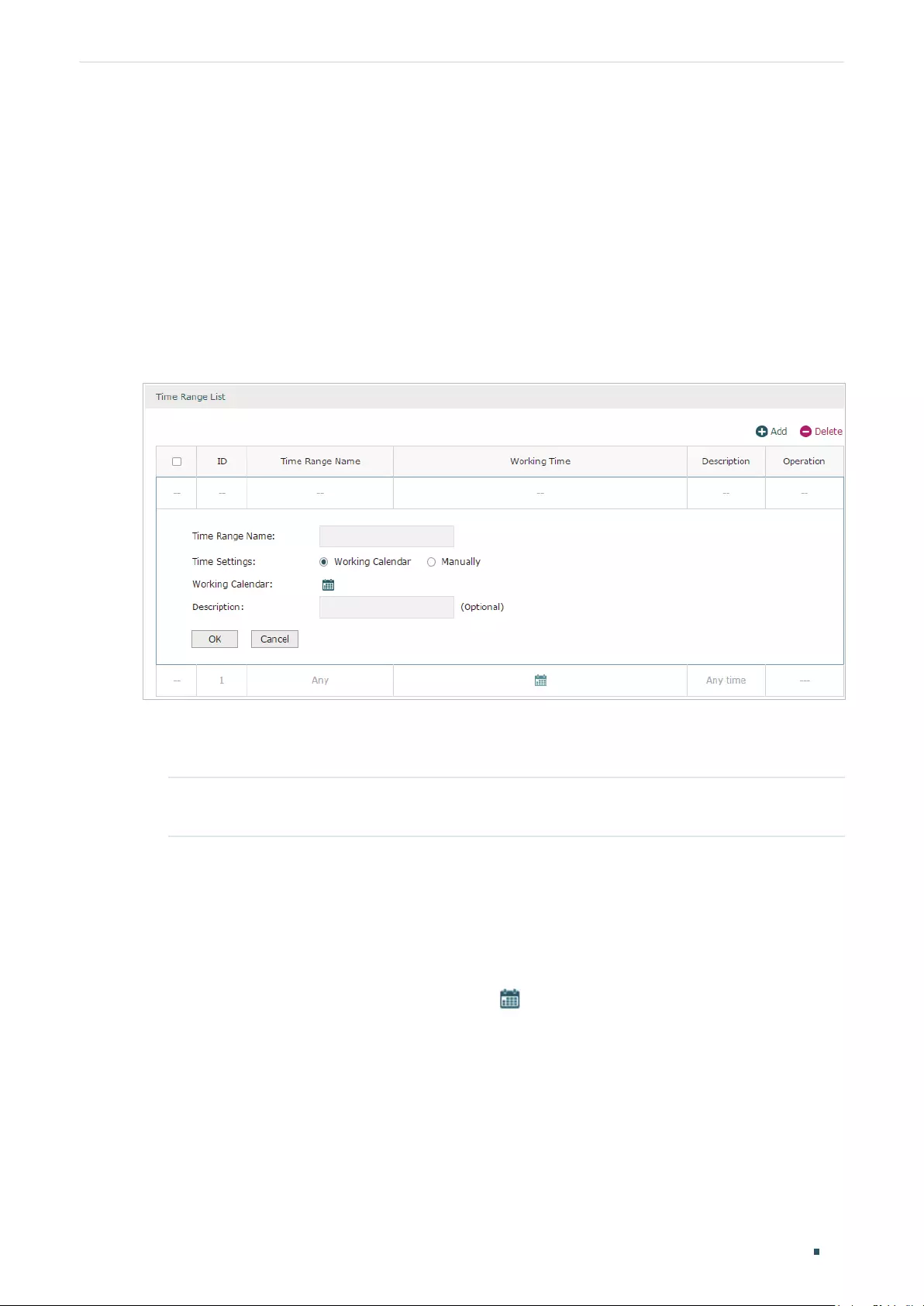
Configuring Preferences Time Range Configuration
User Guide 57
3 Time Range Configuration
Time range configuration allows you to define time ranges by specifying the period in a day
and days in a week. The time range configured here can be used as the effective time for
multiple functions like Bandwidth Control, Link Backup, Policy Routing and so on.
Choose the menu Preferences > Time Range > Time Range and click Add to load the
following page.
Figure 3-1 Add a Time Range Entry
Follow these steps to add a time range entry:
1) Enter a name for the time range entry.
Time Range
Name
Enter a name for the time range entry. Only letters, digits or underscores are
allowed.
2) Choose a mode to set the time range. Two modes are provided: Working Calendar and
Manually.
Working Calendar
Working Calendar mode allows you to set the time range on a calendar. In this mode,
the effective time can be accurate to the hour.
Choose Working Calendar mode and click to load the following page.
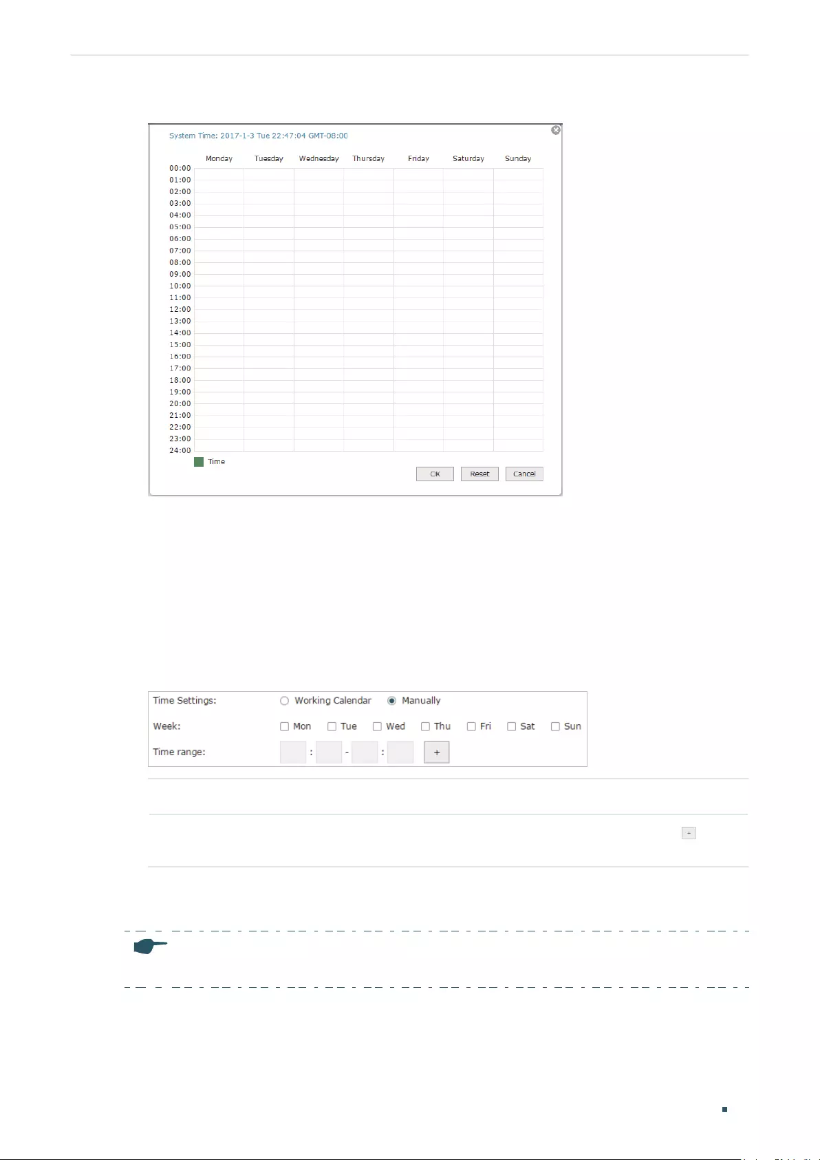
User Guide 58
Configuring Preferences Time Range Configuration
Figure 3-2 Working Calendar Mode
Select the time slices and click OK to set the time range. You can click the time slices,
or alternatively drag the areas to select or deselect the time slices.
Manually
Manually mode allows you to enter the time range and select the effective days in a
week manually. In this mode, effective time can be accurate to the minute.
Choose Manually mode to load the following page.
Figure 3-3 Manually Mode
Week Select the effective days in a week.
Time Range Enter a start and end time. If the effective time is discontinuous, click to add
another time range.
3) (Optional) Enter an brief description of this time range to make identifying it easier.
4) Click OK.
Note:
A time range entry that is being referenced by a rule cannot be deleted.

Configuring Preferences VPN IP Pool Configuration
User Guide 59
4 VPN IP Pool Configuration
The VPN IP pools configured here can be used as the VPN IP address pools when
configuring L2TP VPN and PPTP VPN.
Choose the menu Preferences > VPN IP Pool > VPN IP Pool and click Add to load the
following page.
Figure 4-1 Add an IP Pool Entry
Follow these steps to add an IP Pool:
1) Enter a name and specify the starting and ending IP address of the IP Pool.
IP Pool Name Enter a name for the IP Pool. Only letters, digits or underscores are allowed.
Starting IP Address/
Ending IP Address
Specify the starting and ending IP address. The range of the IP pool cannot
overlap with the existing IP pools.
2) Click OK.
Note:
An IP pool entry that is being referenced by a rule cannot be deleted.
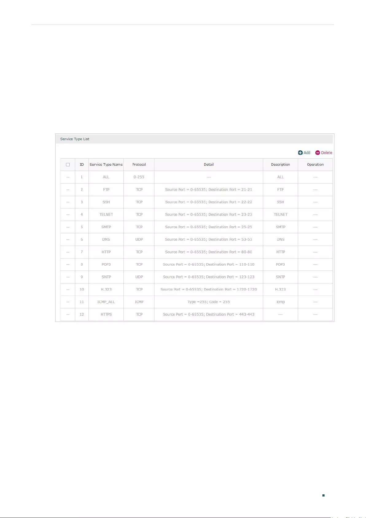
User Guide 60
Configuring Preferences Service Type Configuration
5 Service Type Configuration
The service type entries configured here can be used as part of the matching conditions
when configuring the Access Control rules in Firewall.
Choose the menu Preferences > Service Type > Service Type to load the following page.
Figure 5-1 Service Type List
The entries in gray are system predefined service types. You can add other entries if your
service type is not in the list.
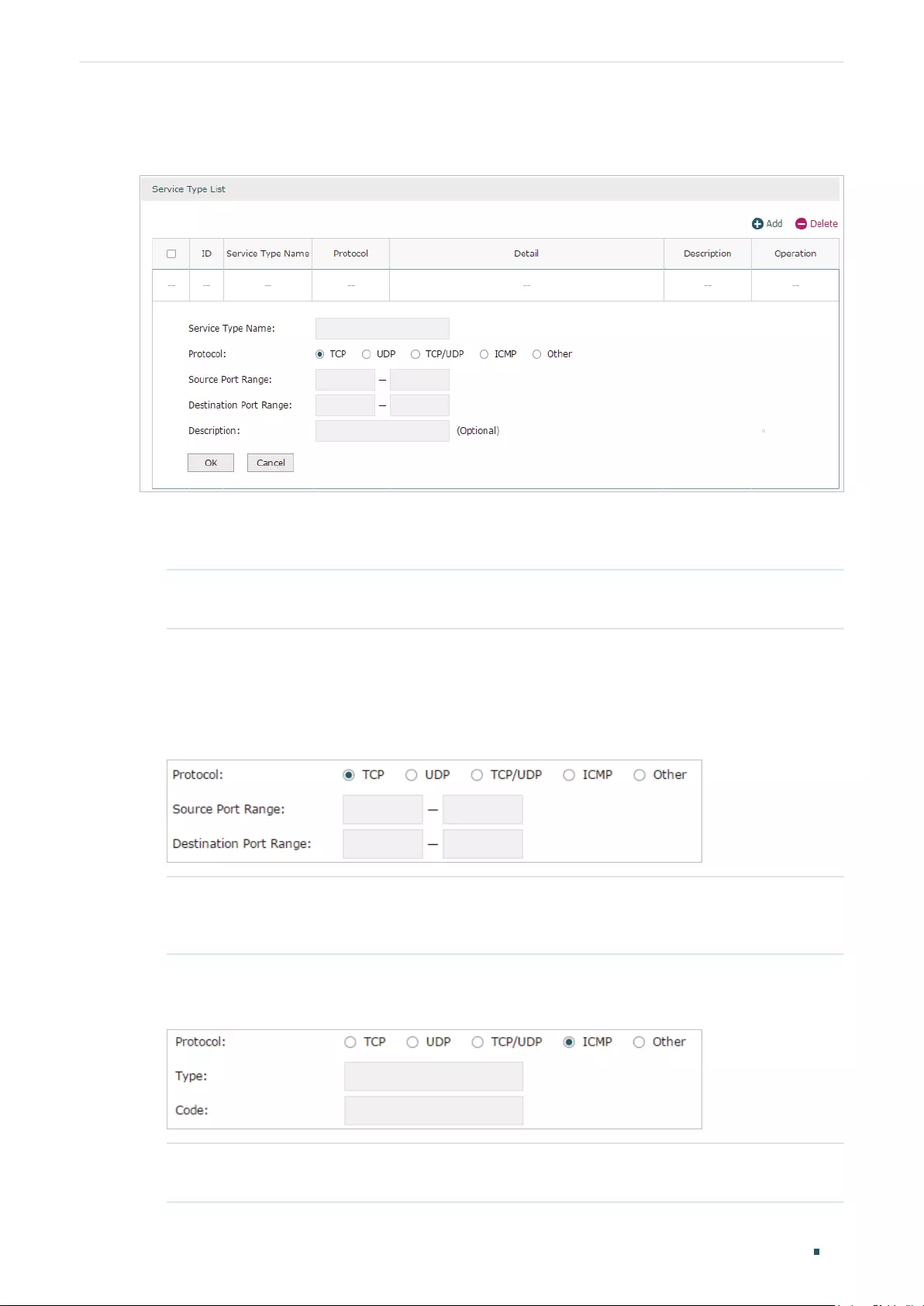
Configuring Preferences Service Type Configuration
User Guide 61
Click Add to load the following page.
Figure 5-2 Add a Service Type Entry
Follow these steps to add a service type entry:
1) Enter a name for the service type.
Service Type Name Enter a name for the service type. Only letters, digits or underscores are
allowed.
2) Select the protocol for the service type. The predefined protocols include TCP, UDP,
TCP/UDP and ICMP. For other protocols, select the option Other.
When TCP, UDP, or TCP/UDP is selected, the following page will appear.
Figure 5-3 TCP/UDP Protocol
Source Port Range/
Destination Port Range
Specify range of the source port and destination port of the TCP or UDP
packets. Packets whose source port and destination port are both in the
range are considered as the target packets.
When ICMP is selected, the following page will appear.
Figure 5-4 ICMP Protocol
Type/Code Specify the type and code of the ICMP packets. ICMP packets with both
the type and code fields matched are considered as the target packets.

User Guide 62
Configuring Preferences Service Type Configuration
When Other is selected, the following page will appear.
Figure 5-5 Other Protocols
Protocol Number Specify the protocol number of the packets. Packets with the protocol
number field matched are considered as the target packets.
3) (Optional) Enter a brief description of this service type to make identifying it easier.
4) Click OK.
Note:
A service type entry that is being referenced by a rule cannot be deleted.

Part 5
Configuring Transmission
CHAPTERS
1. Transmission
2. NAT Configurations
3. Bandwidth Control Configuration
4. Session Limit Configurations
5. Load Balancing Configurations
6. Routing Configurations
7. Configuration Examples

User Guide 64
Configuring Transmission Transmission
1 Transmission
1.1 Overview
Transmission function provides multiple traffic control measures for the network. You can
configure the transmission function according to your actual needs.
1.2 Supported Features
The transmission module includes NAT, Bandwidth Control, Session Limit, Load Balancing
and Routing.
NAT
NAT (Network Address Translation) is the translation between private IP and public IP.
NAT provides a way to allow multiple private hosts to access the public network using one
public IP at the same time, which alleviates the shortage of IP addresses. Furthermore, NAT
strengthens the LAN (Local Area Network) security since the address of LAN host never
appears on the internet. The router supports following NAT features:
Multi-Nets NAT
Multi-Nets NAT function can help the router provide NAT translation for multiple subnets.
One-to-One NAT
One-to-One NAT creates a relationship between a private IP address and a public IP
address. A device with a private IP address can be accessed through the corresponding
valid public IP address.
Virtual Servers
When you build up a server in the local network and want to share it on the internet, Virtual
Servers can realize the service and provide it to the internet users. At the same time
Virtual Servers can keep the local network safe as other services are still invisible from the
internet.
Port Triggering
Port Triggering is a feature used to dynamically forward traffic on a certain port to a
specific server on the local network. When a host in the local network initiates a connection
to the triggering port, all the external ports will be opened for subsequent connections. The
router can record the IP address of the host, when the data from the internet returns to the

Configuring Transmission Transmission
User Guide 65
external ports, the router can forward them to the corresponding host. Port Triggering is
mainly applied to online games, VoIPs, video players and so on.
NAT-DMZ
When a PC is set to be a DMZ (Demilitarized Zone) host in the local network, it is totally
exposed to the internet, which can realize the unlimited bidirectional communication
between internal hosts and external hosts. The DMZ host becomes a virtual server with
all ports opened. When you are not clear about which ports to open in some special
applications, such as IP camera and database software, you can set the PC to be a DMZ
host.
ALG
Some special protocols such as FTP, H.323, SIP, IPSec and PPTP will work properly only
when ALG (Application Layer Gateway) service is enabled.
Bandwidth Control
You can control the bandwidth by configuring bandwidth control rules for limiting various
data flows. In this way, the network bandwidth can be reasonably distributed and utilized.
Session Limit
The amount of TCP and UDP sessions supported by the router is finite. If some local hosts
transmit too many TCP and UDP sessions to the public network, the communication quality
of the other local hosts will be affected, thus it is necessary to limit the sessions of those
hosts.
Load Balancing
You can configure the traffic sharing mode of the WAN ports to optimize the resource
utilization.
Routing
You can configure policy routing rules and static routing.
Policy routing provides a more accurate way to control the routing based on the policy
defined by the network administrator.
Static routing is a form of routing that is configured manually by adding non-aging entries
into a routing table. The manually-configured routing information guides the router in
forwarding data packets to the specific destination.

User Guide 66
Configuring Transmission NAT Configurations
2 NAT Configurations
With NAT configurations, you can:
Configure the Multi-Nets NAT.
Configure the One-to-One NAT.
Configure the Virtual Servers.
Configure the Port Triggering.
Configure the NAT-DMZ.
Configure the ALG.
2.1 Configuring the Multi-Nets NAT
Choose the menu Transmission > NAT > Multi-Nets NAT and click Add to load the
following page.
Figure 2-1 Configuring the Multi-Nets NAT
Follow these steps to configure the Multi-Nets NAT:
1) Specify the name of the Multi-Nets NAT rule and configure other related parameters.
Interface Specify the effective interface for the rule. If you choose multiple ports, the entry
will be applied to all selected ports simultaneously.
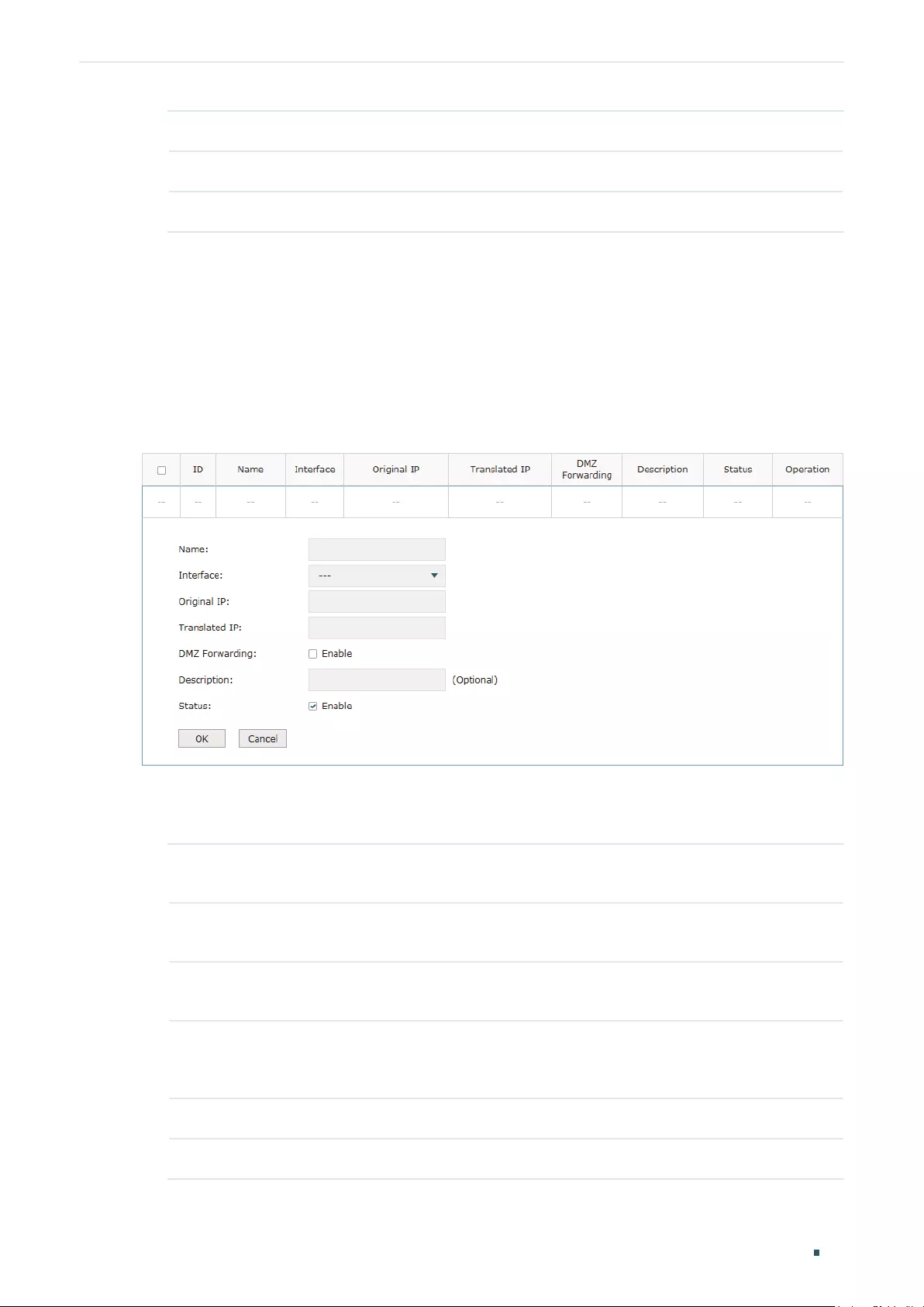
Configuring Transmission NAT Configurations
User Guide 67
Source IP Range Specify the source IP range for the rule.
Status Check the box to enable the rule.
Description Give a description for the rule entry to facilitate your management.
2) Click OK.
2.2 Configuring the One-to-One NAT
Choose the menu Transmission > NAT > One-to-One NAT and click Add to load the
following page.
Figure 2-2 Configuring the One-to-One NAT
Follow these steps to configure the One-to-One NAT:
1) Specify the name of the One-to-One NAT rule and configure other related parameters.
Interface Specify the effective interface for the rule. If you choose multiple ports, the entry
will be applied to all selected ports simultaneously.
Original IP Specify the original IP address for the rule. The original IP address cannot be the
broadcast address, network address or IP address of the interface.
Translated IP Specify the translated IP address for the rule. The translated IP address cannot be
the broadcast address, network address or IP address of the interface.
DMZ Forwarding Check the box to enable DMZ Forwarding. The packets transmitted to the
translated IP address will be forwarded to the host of original IP address if DMZ
Forwarding is enabled.
Description Give a description for the rule entry to facilitate your management.
Status Check the box to enable the rule.
2) Click OK.

User Guide 68
Configuring Transmission NAT Configurations
Note:
One-to-One NAT takes effect only when the connection type of WAN is Static IP.
2.3 Configuring the Virtual Servers
Choose the menu Transmission > NAT > Virtual Servers and click Add to load the
following page.
Figure 2-3 Configuring the Virtual Servers
Follow these steps to configure the Virtual Servers:
1) Specify the name of the Virtual Server rule and configure other related parameters.
Interface Specify the effective interface for the rule. If you choose multiple ports, the entry
will be applied to all selected ports simultaneously.
External Port Enter the service port or port range the router provided for accessing external
network. The ports or port ranges cannot overlap with those of other virtual
server rules.
Internal Port Specify the service port or port range of the LAN host as virtual server.
Internal Server
IP
Enter the IP address of the specified internal server for the entry. All the requests
from the internet to the specified LAN port will be redirected to this host.
Protocol Specify the protocol used for the entry.
Status Check the box to enable the rule.
2) Click OK.

Configuring Transmission NAT Configurations
User Guide 69
2.4 Configuring the Port Triggering
Choose the menu Transmission > NAT > Port Triggering and click Add to load the
following page.
Figure 2-4 Configuring the Port Triggering
Follow these steps to configure the Port Triggering:
1) Specify the name of the Port Triggering rule and configure other related parameters.
Interface Specify the effective interface for the rule. If you choose multiple ports, the entry
will be applied to all selected ports simultaneously.
Trigger Port Enter the trigger port or port range. Each entry supports at most 5 groups of
trigger ports. For example, you can enter 1-2, 3-4, 5-6, 7-8, 8-9. Note that the
ports or port ranges cannot overlap with those of other port triggering rules.
Trigger Protocol Specify the trigger protocol for the trigger port.
Incoming Port Enter the incoming port or port range. Each entry supports at most 5 groups of
incoming ports. For example, you can enter 1-2, 3-4, 5-6, 7-8, 8-9. Note that the
ports or port ranges cannot overlap with those of other port triggering rules.
Incoming
Protocol
Specify the incoming protocol for the incoming port.
Status Check the box to enable the rule.
2) Click OK.

User Guide 70
Configuring Transmission NAT Configurations
2.5 Configuring the NAT-DMZ
Choose the menu Transmission > NAT > NAT-DMZ and click Add to load the following
page.
Figure 2-5 Configuring the NAT-DMZ
Follow these steps to configure the NAT-DMZ:
1) Specify the name of the NAT-DMZ rule and configure other related parameters.
Interface Specify the effective interface for the rule. If you choose multiple ports, the entry
will be applied to all selected ports simultaneously.
Host IP Address Specify the host IP address for NAT-DMZ.
Status Check the box to enable the rule.
2) Click OK.
2.6 Configuring the ALG
Choose the menu Transmission > NAT > ALG to load the following page.
Figure 2-6 Configuring the ALG
Enable related ALG according to your needs and click Save.
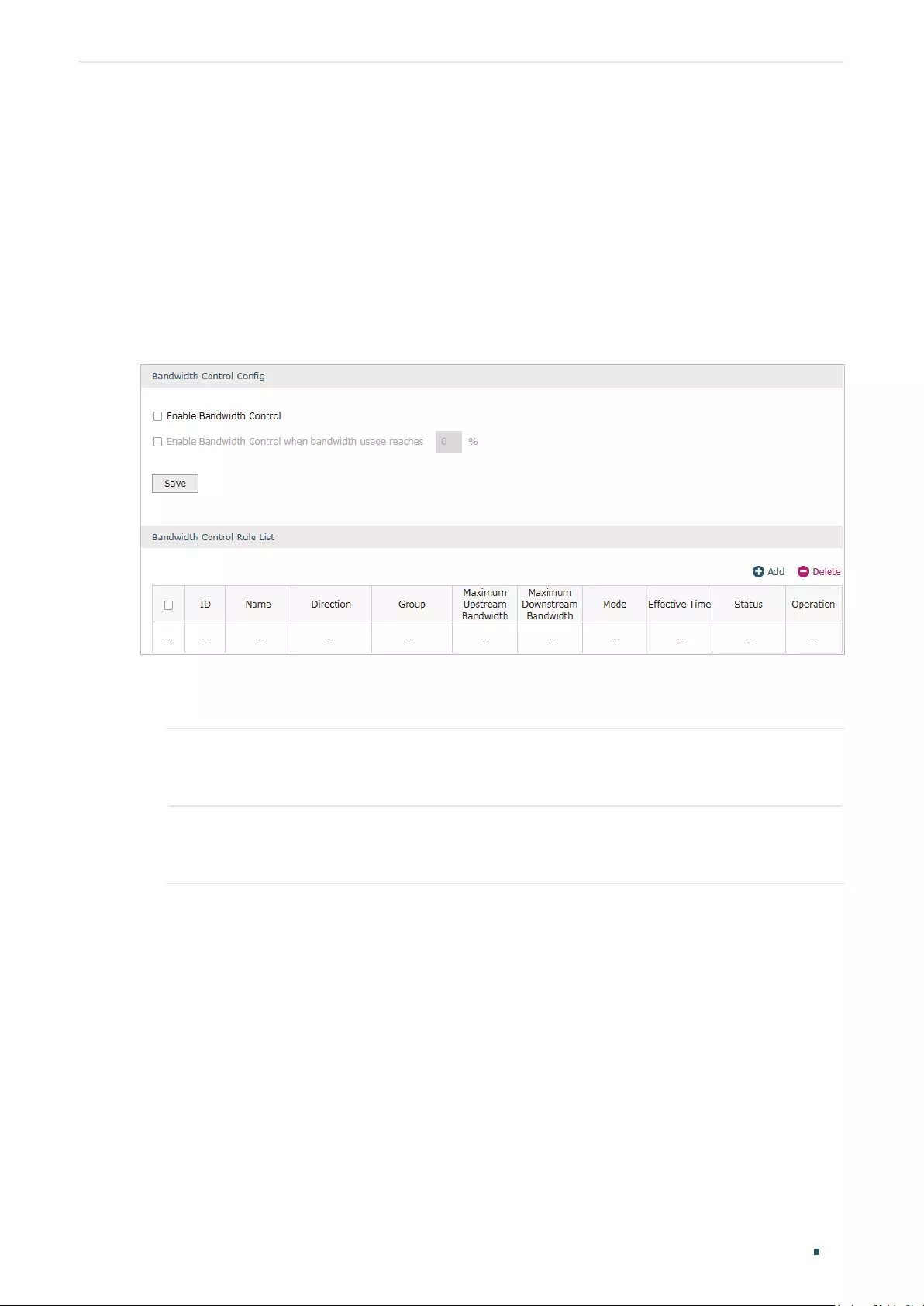
Configuring Transmission Bandwidth Control Configuration
User Guide 71
3 Bandwidth Control Configuration
Bandwidth Control functions to control the bandwidth by configuring rules for limiting
various data flows. In this way, the network bandwidth can be reasonably distributed and
utilized.
Choose the menu Transmission> Bandwidth Control to load the following page.
Figure 3-1 Configuring the Bandwidth Control
Follow these steps to configure the Bandwidth Control rule:
1) In the Bandwidth Control Config Section, enable Bandwidth Control function globally.
Enable
Bandwidth
Control
Check the box to enable Bandwidth Control globally.
Enable
Bandwidth
Control When
With “Enable Bandwidth Control” selected, you can specify a percentage, and the
Bandwidth Control will take effect only when the bandwidth usage reaches the
percentage you specified.
2) In the Bandwidth Control Rule List section, click Add to load the following page.

User Guide 72
Configuring Transmission Bandwidth Control Configuration
Figure 3-2 Add Bandwidth Control rules
Specify the name of the Bandwidth Control rule and configure other related parameters.
Then click OK.
Direction Specify the data stream direction for the rule.
Group Specify the address group for the rule to define the controlled users. The IP group
referenced here can be created on the Preferences > IP Group > IP Group page.
Maximum
Upstream
Bandwidth
Specify the Maximum Upstream Bandwidth in Kbps for the rule.
Maximum
Downstream
Bandwidth
Specify the Maximum Downstream Bandwidth in Kbps for the rule.
Mode Specify the bandwidth control mode for the address group.
Individual means the bandwidth of each user is equal to the current bandwidth of
this entry.
Shared means the total bandwidth of all controlled IP addresses is equal to the
current bandwidth of this entry.
Effective Time Specify the time for the rule to take effect. Any means it always takes effect. The
time range referenced here can be created on the Preference > Time Range >
Time Range page.
Description Enter a brief description for the rule.
ID Append the rule to the right position to give a priority for the rule.
Status Check the box to enable the rule.
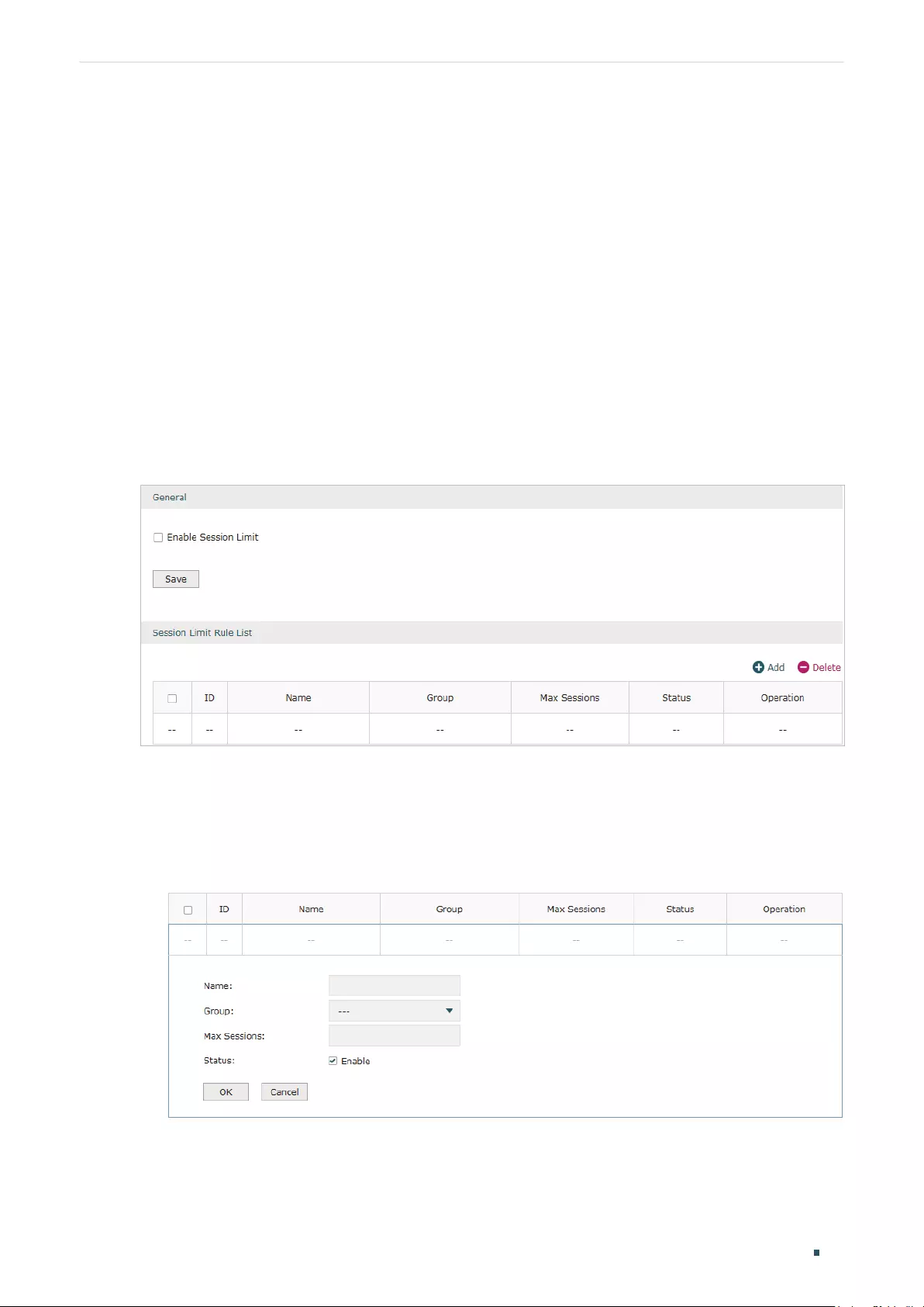
Configuring Transmission Session Limit Configurations
User Guide 73
4 Session Limit Configurations
To complete Session Limit configuration, follow these steps:
1) Configure session limit.
2) View the session limit information.
4.1 Configuring Session Limit
Choose the menu Transmission> Session Limit > Session Limit to load the following
page.
Figure 4-1 Configuring the Session Limit
Follow these steps to configure the Session Limit rule:
1) In the General Section, enable Session Limit function globally.
2) In the Session Limit Rule List section, click Add to load the following page.
Figure 4-2 Add Session Limit rules
Specify the name of the Session Limit rule and configure other related parameters.
Then click OK.

User Guide 74
Configuring Transmission Session Limit Configurations
Group Specify the address group to which the rule will be applied. The IP group
referenced here can be created on the Preferences > IP Group > IP Group page.
Max Sessions Specify the max sessions for the controlled users.
Status Check the box to enable the rule.
4.2 Viewing the Session Limit Information
Choose the menu Transmission> Session Limit > Session Monitor to load the following
page.
Figure 4-3 Viewing the Session Limit Information
View the Session Limit information of hosts configured with Session Limit. Click the
Refresh button to get the latest information.
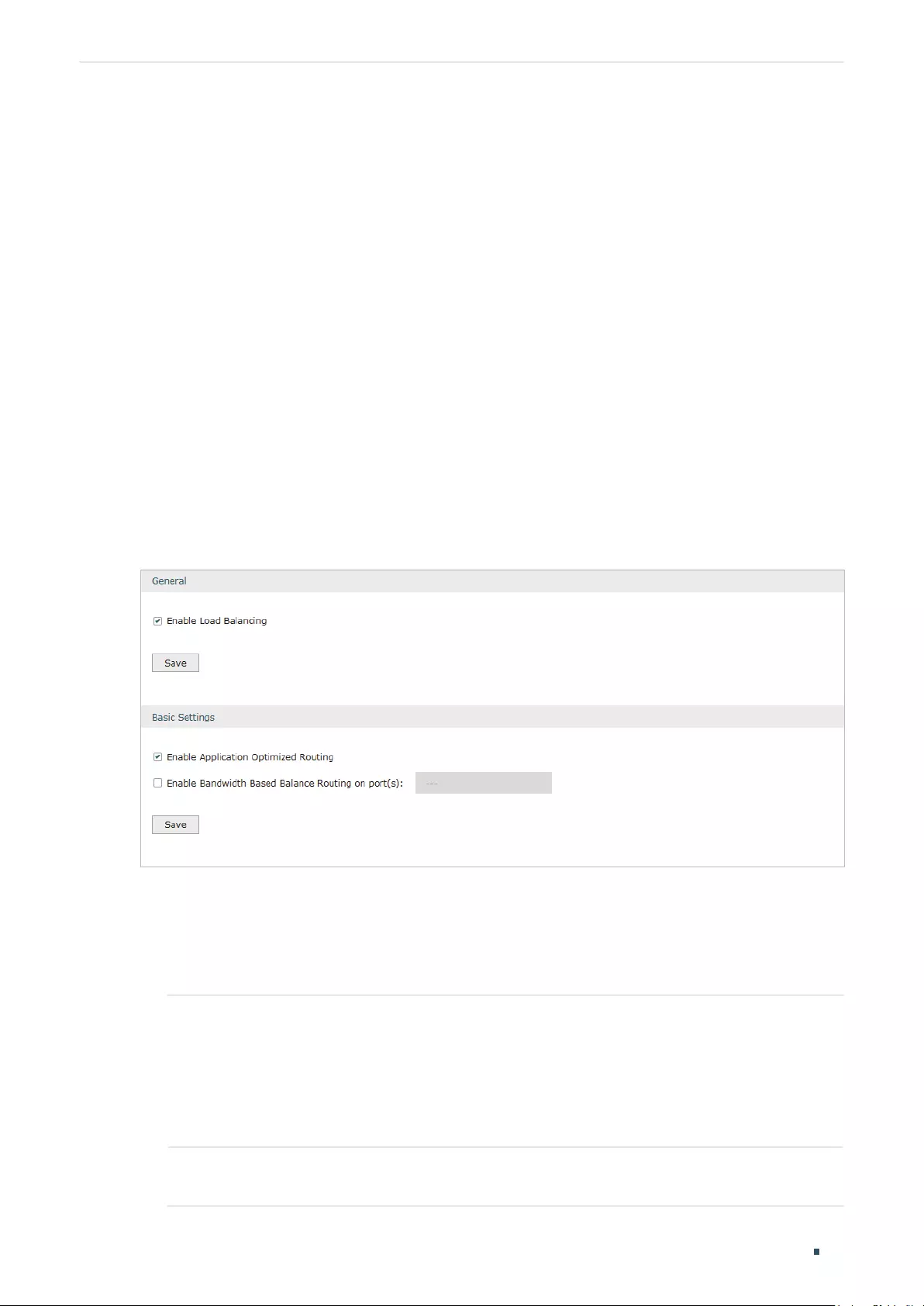
Configuring Transmission Load Balancing Configurations
User Guide 75
5 Load Balancing Configurations
With load balancing configurations, you can:
Configure the load balancing
Configure the link backup
Configure the online detection
5.1 Configuring the Load Balancing
Choose the menu Transmission> Load Balancing > Basic Settings to load the following
page.
Figure 5-1 Configuring the Load Balancing
Follow these steps to configure the load balancing:
1) In the General Section, enable load balancing function globally and click Save.
2) In the Basic Settings section, select the appropriate method for load balancing and
click Save.
Enable Application
Optimized Routing
With Application Optimized Routing enabled, the router will consider
the source IP address and destination IP address (or destination port)
of the packets as a whole and record the WAN port they pass through.
Then the packets with the same source IP address and destination IP
address (or destination port) will be forwarded to the recorded WAN
port. This feature ensures that multi-connected applications work
properly.
Enable Bandwidth Based
Balance Routing on port(s)
Select the WAN port from the drop-down list to enable Bandwidth
Based Balance Routing.
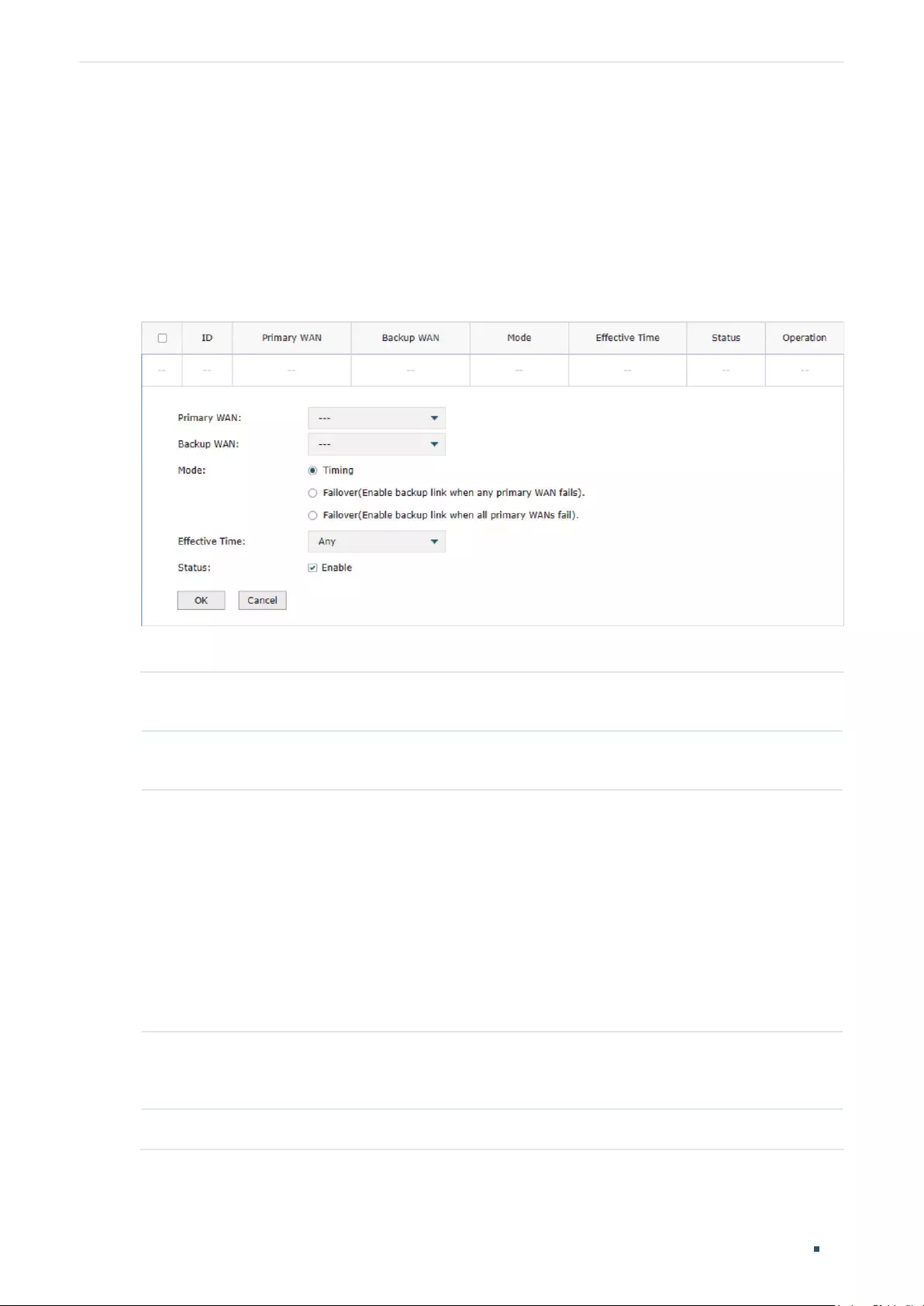
User Guide 76
Configuring Transmission Load Balancing Configurations
5.2 Configuring the Link Backup
With Link Backup function, the router will switch all the new sessions from dropped line(s)
automatically to another to keep an always on-line network.
Choose the menu Transmission> Load Balancing > Link Backup and click Add to load the
following page.
Figure 5-2 Configuring the Link Backup Rule
Configure the following parameters on this page and click OK.
Primary WAN Specify the primary WAN port. You can choose one primary WAN port, or choose
multiple primary WAN ports to perform load balance.
Backup WAN Specify the backup WAN port to back up the traffic for the primary WAN port under
the specified condition.
Mode Specify the mode as Timing or Failover.
Timing: Link Backup will be enabled if the specified effective time is reached. All the
traffic on the primary WAN will switch to the backup WAN at the beginning of the
effective time; the traffic on the backup WAN will switch to the primary WAN at the
ending of the effective time.
Failover (Enable backup link when any primary WAN fails): Link Backup will be enabled
when any primary WAN fails.
Failover (Enable backup link when all primary WANs fail): Link Backup will be enabled
only when all primary WANs fail.
Effective Time Specify the time for the rule to take effect in Timing mode. “Any” means it takes effect
at any time. The time range referenced here can be created on the Preference > Time
Range > Time Range page.
Status Check the box to enable the rule.

Configuring Transmission Load Balancing Configurations
User Guide 77
5.3 Configuring the Online Detection
With Online Detection function, you can detect the online status of the WAN port.
Choose the menu Transmission> Load Balancing > Online Detection and click to load
the following page.
Figure 5-3 Configuring the Online Detection
Configure the following parameters on this page and click OK.
Port Displays the name of WAN Port.
Mode Select the online detection mode.
Auto: In Auto Mode, the DNS server of the WAN port will be selected as the destination
for DNS Lookup to detect whether the WAN is online.
Manual: In Manual Mode, you can configure the destination IP address for PING and
DNS Lookup manually to detect whether the WAN is online.
Always Online: In Always Online Mode, the status of the port will always be online.
Ping With “Manual Mode” selected, specify the destination IP for Ping. The corresponding
port will ping the IP address to detect whether the WAN port is online. 0.0.0.0 means
Ping detection is disabled.
DNS Lookup With “Manual Mode” selected, specify the IP address of DNS server. The
corresponding port will perform the DNS lookup using default domain name to detect
whether the WAN port is online. 0.0.0.0 means DNS Lookup is disabled.
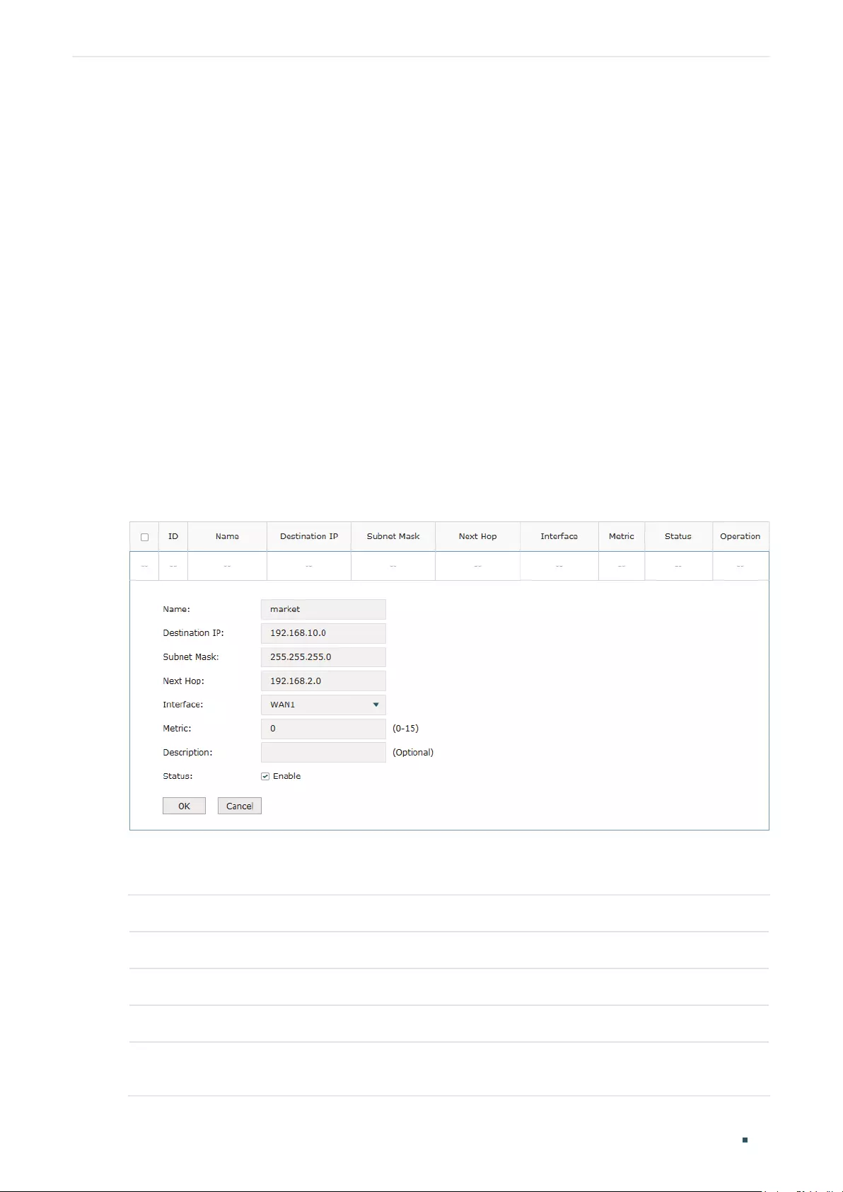
User Guide 78
Configuring Transmission Routing Configurations
6 Routing Configurations
With routing configurations, you can:
Configure the static routing
Configure the policy routing rule
View the routing table
6.1 Configuring the Static Routing
Choose the menu Transmission> Routing > Static Route and click Add to load the
following page.
Figure 6-1 Configuring the Static Routing
Specify the name of the static route entry and configure other related parameters. Then
click OK.
Destination IP Specify the destination IP address the route leads to.
Subnet Mask Specify the subnet mask of the destination network.
Next Hop Specify the IP address to which the packet should be sent next.
Interface Specify the physical network interface through which this route is accessible.
Metric Define the priority of the route. A smaller value means a higher priority. The default
value is 0. It is recommended to keep the default value.
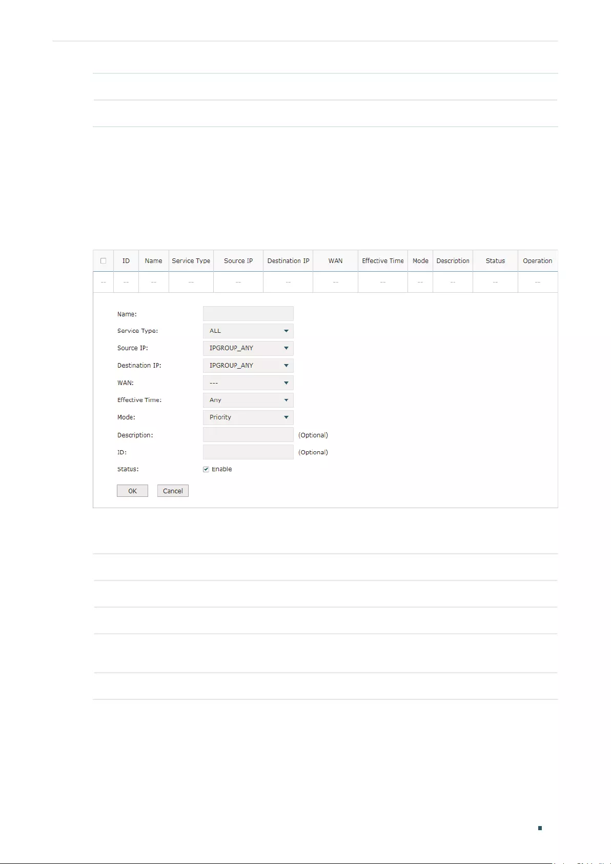
Configuring Transmission Routing Configurations
User Guide 79
Description Enter a brief description for the rule.
Status Check the box to enable the rule.
6.2 Configuring the Policy Routing
Choose the menu Transmission> Routing > Policy Routing and click Add to load the
following page.
Figure 6-2 Configuring the Policy Routing
Specify the name of the policy routing entry and configure other related parameters. Then
click OK.
Service Type Specify the service type for the rule.
Source IP Enter the source IP range for the rule. 0.0.0.0 — 0.0.0.0 means any IP is acceptable.
Destination IP Enter the destination IP range for the rule. 0.0.0.0 — 0.0.0.0 means any IP is acceptable.
WAN Specify the outcoming port for the rule. If you choose multiple ports, the entry will be
applied to all selected ports simultaneously.
Effective Time Specify the effective time for the rule.

User Guide 80
Configuring Transmission Routing Configurations
Mode Specify the policy routing mode for the rule.
Priority: In Priority Mode, the rule depends on the online detection result. If any WAN
port that you specify is online, the rule will take effect. If all the WAN ports that you
specify are offline, the rule will not take effect.
Only: In Only Mode, the rule always takes effect regardless of the WAN port status or
online detection result.
Description Enter a brief description for the rule.
Status Check the box to enable the rule.
6.3 Viewing the Routing Table
Choose the menu Transmission> Routing > Routing Table to load the following page.
Figure 6-3 Routing Table
The Routing Table shows the information of the current route entries.
Destination IP Displays the destination IP address the route leads to.
Subnet Mask Displays the subnet mask of the destination network.
Next Hop Displays the gateway IP address to which the packet should be sent next.
Interface Displays the physical network interface through which this route is accessible.
Metric Displays the metric to reach the destination IP address.

Configuring Transmission Configuration Examples
User Guide 81
7 Configuration Examples
7.1 Example for Configuring NAT
7.1.1 Network Requirements
A company has two departments: Market Department and RD department. Each
department is assigned to an individual subnet. The company has the following
requirements:
1) The two departments need to access the internet via the same gateway router.
2) The company has a web server which needs to be accessed by the users on the
internet.
7.1.2 Network Topology
Figure 7-1 Network Topology
Internet
L3 Switch
Web Server
Gateway Router
RD Department
172.16.10.0/24
Market Department
172.16.20.0/24
WAN1
LAN
192.168.0.10
192.168.0.20 123.1.1.3
7.1.3 Configuration Scheme
To meet the first requirement, add Multi-nets NAT entries for the two departments
respectively on the gateway router, thus the router can translate and deliver packets
whose source IP addresses are in different subnets from the router’s LAN IP segment.
Then configure static routing on the gateway router to make sure the router know where to
deliver the packets to IP addresses in different subnets (172.16.10.0/24, 172.16.20.0/24).

User Guide 82
Configuring Transmission Configuration Examples
To meet the second requirement, add One-to-One NAT entry for the Web Server on
the gateway router, thus the web server with a private IP address can be accessed at a
corresponding valid public IP address. Note that One-to-One NAT take effects only when
the connection type of WAN port is Static IP.
7.1.4 Configuration Procedure
Follow the steps below to configure NAT on the gateway router:
Configuring the Multi-Nets NAT
1) Choose the menu Transmission > NAT > Multi-Nets NAT to load the configuration
page, and click Add.
2) Add Multi-nets NAT entries for the two departments respectively: Specify the entry
name as RD/Market, choose the interface as WAN1, and enter the network address
of the RD/Market department as source IP range. Keep Status of this entry as Enable.
Click OK.
Figure 7-2 Adding a Multi-Nets Entry for RD Department
Figure 7-3 Adding a Multi-Nets Entry for Market Department
Configuring the static routing
1) Choose the menu Transmission > Routing > Static Route to load the configuration
page, and click Add.
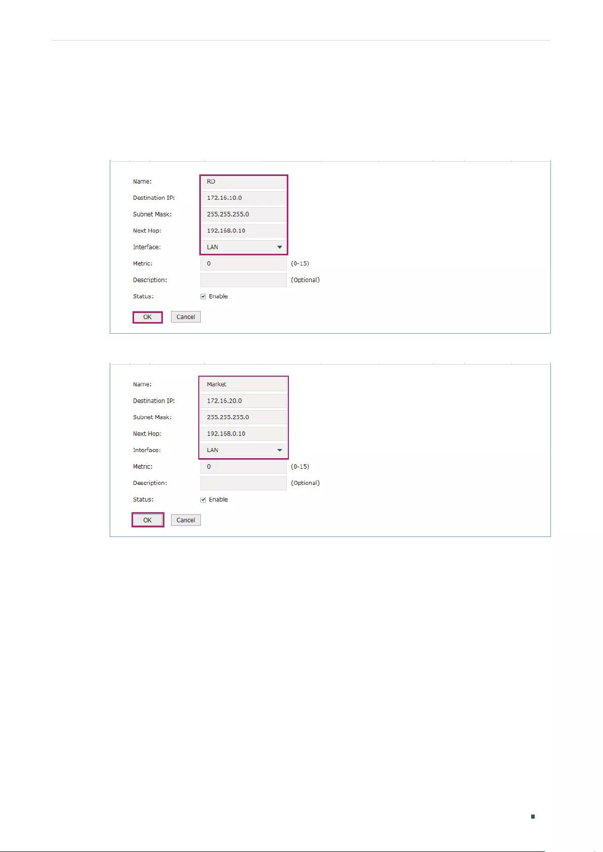
Configuring Transmission Configuration Examples
User Guide 83
2) Add static routes for the two departments respectively: Specify the entry name as RD/
Market, enter 172.16.10.0/172.16.20.0 as the destination IP, and specify the VLAN 1
interface IP of L3 switch as next hop, then choose the interface as WAN1. Keep Status
of this entry as Enable. Click OK.
Figure 7-4 Configuring the Static Routing for RD Department
Figure 7-5 Configuring the Static Routing for Market Department
Configuring the One-to-One NAT
1) Choose the menu Transmission > NAT > One-to-One NAT to load the configuration
page, and click Add.
2) Add a One-to-One NAT entry for the web server: Specify the entry name as web,
choose the interface as WAN1, and enter the original IP as 192.168.0.20, the translated
IP as 123.1.1.3. Enable DMZ Forwarding, then keep Status of this entry as Enable. Click
OK.

User Guide 84
Configuring Transmission Configuration Examples
Figure 7-6 Adding a Multi-Nets Entry for RD Department
7.2 Example for Configuring Load Balancing
7.2.1 Network Requirements
To make good use of bandwidth, the network administrator decides to bind two WAN links
using load balancing.
7.2.2 Network Topology
Figure 7-7 Network Topology
Internet Internet
WAN1
PPPoE 8Mbps
WAN2
Dynamic IP 12Mbps
Router
PC
7.2.3 Configuration Scheme
To meet the requirement, configure WAN parameters on the router in order that the
two WAN links can work properly and have access to the internet, then configure load
balancing on the router to aggregate two WAN links.

Configuring Transmission Configuration Examples
User Guide 85
7.2.4 Configuration Procedure
Follow the steps below to configure load balancing on the router:
Configuring the WAN parameters
For WAN1 port, configure the connection type as PPPoE, and specify Upstream and
Downstream bandwidth for this link based on your ADSL bandwidth (You could consult
your internet Service Provider for the bandwidth information).
For WAN2 port, configure the connection type as Dynamic IP, and specify Upstream
and Downstream bandwidth for this link according to data that ISP provides.
Make sure two WAN links can work properly and have access to the internet.
Configuring the Load Balancing
Choose the menu Transmission> Load Balancing > Basic Settings to load the
configuration page. Enable Load Balancing globally, and click Save. Enable Application
Optimized Routing, and enable Bandwidth Based Balancing Routing on WAN1 port and
WAN2 port. Click Save.
Figure 7-8 Configuring the Load Balancing
7.3 Example for Configuring Virtual Server
7.3.1 Network Requirements
The network administrator builds up a FTP server on the local network and wants to share it
on the internet.

User Guide 86
Configuring Transmission Configuration Examples
7.3.2 Network Topology
Figure 7-9 Network Topology
Internet
PC
Router
FTP Server
IP:192.168.0.100
LAN WAN1
7.3.3 Configuration Scheme
In this scenario, both virtual server and DMZ host can be configured to meet the
requirement. Here we take configuring Virtual Server as an example, owing to that for a
DMZ host all ports are open which may result in unsafety. Configure the FTP server as a
virtual server on the router so that the FTP server can be accessed by the internet user.
7.3.4 Configuration Procedure
Follow the steps below to configure virtual server on the router:
1) Choose the menu Network > NAT > Virtual Servers to load the configuration page, and
click Add.
2) Specify the entry name as ftp, choose the interface as WAN1, and specify the internal/
external port as 21, enter the IP address of FTP server (192.168.0.100) as the internal
server IP. Select the protocol as All, then keep Status of this entry as Enable. Click OK.
Figure 7-10 Configuring the Virtual Server

Configuring Transmission Configuration Examples
User Guide 87
7.4 Example for Configuring Policy Routing
7.4.1 Network Requirements
The network administrator has a router with 3 computers (192.168.0.2-192.168.0.4)
connected to the LAN side, all computers are routed to internet by WAN1 port and WAN2
port, the requirements are as follows:
WAN2 link is used to backup WAN1 link to keep an always on-line network.
The two computers with IP addresses 192.168.0.2 and 192.168.0.3 are required to use
WAN1 for web surfing, WAN2 for other internet activities.
7.4.1 Network Topology
Figure 7-11 Network Topology
WAN1 WAN2
Router
PC
PC PC
192.168.0.2 192.168.0.3 192.168.0.4
Internet Internet
7.4.2 Configuration Scheme
To meet the first requirement, configure link backup on the router. To meet the second
requirement, configure policy routing rules for two computers which use 192.168.0.2 and
192.168.0.3. Note that link backup rule has a higher priority than policy routing rule.
7.4.3 Configuration Procedure
Follow the steps below to configure link backup and policy routing on the router:
Configuring the Link Backup
1) Choose the menu Transmission > Load Balancing > Link Backup to load the
configuration page, and click Add.
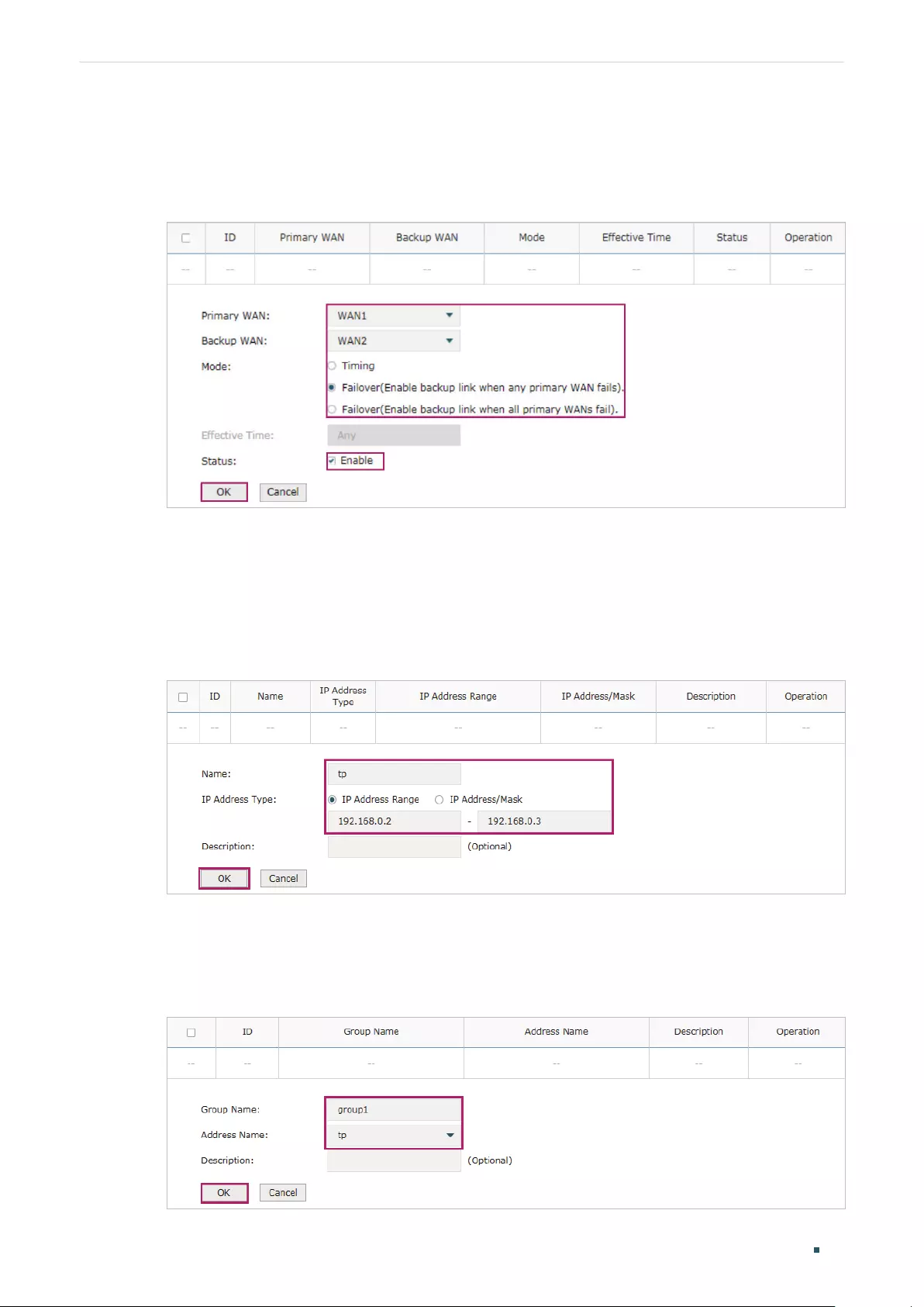
User Guide 88
Configuring Transmission Configuration Examples
2) Specify the primary WAN as WAN1, the backup WAN as WAN2 and the mode as
Failover (Enable backup link when any primary WAN fails). When WAN1 has failed,
WAN2 will be enabled. Keep Status of this entry as Enable. Click OK.
Figure 7-12 Configuring the Link Backup
Configuring the Policy Routing Rules
1) Choose the menu Preferences > IP Group > IP Address to load the configuration page,
and click Add. Specify the IP address name as tp, the IP address type as IP Address
Range (192.168.0.2-192.168.0.3). Click OK.
Figure 7-13 Configuring the IP Address
2) Choose the menu Preferences > IP Group > IP Address to load the configuration
page and click Add. Specify the IP group name as group1, the IP address name as tp to
reference the IP address you have created. Click OK.
Figure 7-14 Configuring the IP Group
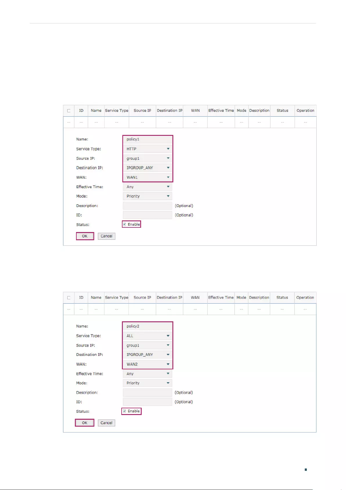
Configuring Transmission Configuration Examples
User Guide 89
3) Choose the menu Transmission > Routing > Policy routing to load the configuration
page, and click Add.
Specify the policy routing rule name as policy1, the service type as HTTP, the source IP
as group1, the destination IP as IPGROUP_ANY which means no limit. Choose WAN1,
and keep Status of this entry as Enable. Click OK.
Figure 7-15 Configuring the Policy Routing Rule 1
Specify the policy routing rule name as policy2, the service type as ALL, the source IP
as group1, the destination IP as IPGROUP_ANY which means no limit. Choose WAN2,
and keep Status of this entry as Enable. Click OK.
Figure 7-16 Configuring the Policy Routing Rule 2

Part 6
Configuring Firewall
CHAPTERS
1. Firewall
2. Firewall Configuration
3. Configuration Examples

Configuring Firewall Firewall
User Guide 91
1 Firewall
1.1 Overview
Firewall is used to enhance the network security. It can prevent external network threats from
spreading to the internal network, protect the internal hosts from ARP attacks, and control the
internal users’ access to the external network.
1.2 Supported Features
The Firewall module supports four functions: Anti ARP Spoofing, Attack Defense, MAC Filtering
and Access Control.
Anti ARP Spoofing
ARP (Address Resolution Protocol) is used to map IP addresses to the corresponding MAC
addresses so that packets can be delivered to their destinations. However, since ARP is
implemented with the premise that all the hosts and gateways are trusted, there are high
security risks on real, complex networks. If attackers send ARP spoofing packets with false IP
address-to-MAC address mapping entries, the device will update the ARP table based on the
false ARP packets and record wrong mapping entries, which results in a breakdown of normal
communication.
Anti ARP Spoofing can protect the network from ARP spoofing attacks. It works based on the
IP-MAC Binding entries. These entries record the correct one-to-one relationships between IP
addresses and MAC addresses. When receiving an ARP packet, the router checks whether it
matches any of the IP-MAC Binding entries. If not, the router will ignore the ARP packets. In this
way, the router maintains the correct ARP table.
In addition, the router provides the following two sub functions:
Permitting the packets matching the IP-MAC Binding entries only and discarding other
packets.
Sending GARP packets to the hosts when it detects ARP attacks. The GARP packets can
inform hosts of the correct ARP table, preventing their ARP tables from being falsified by
ARP spoofing packets.
Attack Defense
Attacks on a network device can cause device or network paralysis. With the Attack Defense
feature, the router can identify and discard various attack packets which are sent to the CPU,
and limit the packet receiving rate. In this way, the router can protect itself and the connected
network against malicious attacks.

User Guide 92
Configuring Firewall Firewall
The router provides two types of Attack Defense: Flood Defense and Packet Anomaly Defense.
Flood Defense limits the receiving rate of the specific types of packets, and Packet Anomaly
Defense discards the illegal packets directly.
MAC Filtering
MAC Filtering can flexibly control the access to the network of the specific hosts. You can
simply add the MAC addresses of the hosts to the MAC Filtering List and specify the filtering
rule for these hosts. Two rules are provided: allow the packets with the MAC addresses in the
MAC Filtering List and deny other packets, or deny the packets with the MAC addresses in the
MAC Filtering List and allow other packets.
Access Control
Access Control can filter the packets passing through the router based on the Access Control
rules. An Access Control rule includes a filter policy and some conditions, such as service
type, receiving interface and effective time. The router will apply the filter policy to the packets
matching these conditions, and thus to limit network traffic, manage network access behaviors
and more.
Access Control can prevent various network attacks, such as attacks on TCP (Transmission
Control Protocol) and ICMP (Internet Control Message Protocol) packets, and can also manage
network access behaviors, such as controlling access to the internet.

Configuring Firewall Firewall Configuration
User Guide 93
2 Firewall Configuration
In Firewall module, you can configure the following features:
Anti ARP Spoofing
Attack Defense
MAC Filtering
Access Control
2.1 Anti ARP Spoofing
To complete Anti ARP Spoofing configuration, there are two steps. First, add IP-MAC Binding
entries to the IP-MAC Binding List. Then enable Anti ARP Spoofing for these entries.
Note:
In case Anti ARP Spoofing causes access problems to the currently connected devices, we
recommend that you add and verify the IP-MAC Binding entries first before enabling Anti ARP
Spoofing.
2.1.1 Adding IP-MAC Binding Entries
You can add IP-MAC Binding entries in two ways: manually and via ARP scanning.
Adding IP-MAC Binding Entries Manually
You can manually bind the IP address and MAC address together on the condition that you
have got the related information of the hosts on the network.
Adding IP-MAC Binding Entries via ARP Scanning
With ARP Scanning, the router sends the ARP request packets with the specific IP field to the
hosts. Upon receiving the ARP reply packet, the router can get the IP address, MAC address
and connected interface of the host.
The following sections introduce these two methods in detail.

User Guide 94
Configuring Firewall Firewall Configuration
Adding IP-MAC Binding Entries Manually
Before adding entries manually, get the IP addresses and MAC addresses of the hosts on
the network and make sure of their accuracy.
Choose the menu Firewall > Anti ARP Spoofing > IP-MAC Binding to load the following
page.
Figure 2-1 IP-MAC Binding Page
Follow the steps below to add IP-MAC Binding entries manually.
1) In the IP-MAC Binding List section, click Add to load the following page.
Figure 2-2 Add IP-MAC Binding Entries Manually
2) Configure the following parameters on this page.
IP Address Enter an IP address to be bound.
MAC Address Enter a MAC address to be bound.
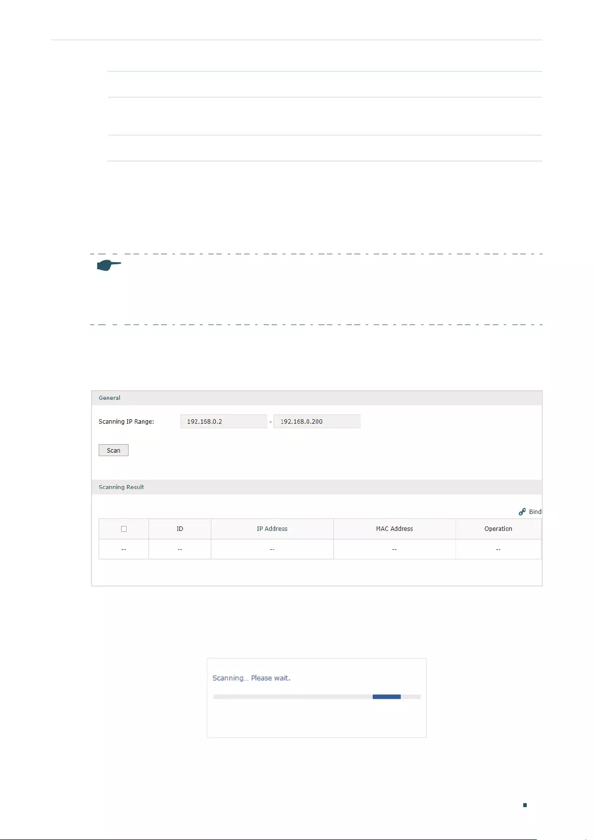
Configuring Firewall Firewall Configuration
User Guide 95
Description Give a description for identification.
Export to DHCP
Address Reservation
Choose to whether export the entry to the DHCP Address Reservation list.
Status Enable this entry. Only when the status is Enable will this entry be effective.
3) Click OK and the added entry will be displayed in the list.
Adding IP-MAC Binding Entries via ARP Scanning
If you want to get the IP addresses and MAC addresses of the hosts quickly, you can use
ARP Scanning to facilitate your operation.
Note:
Before using this feature, make sure that your network is safe and the hosts are not suffering from
ARP attacks at present; otherwise, you may obtain incorrect IP-MAC Binding entries. If your network
is being attacked, it’s recommended to bind the entries manually.
Choose the menu Firewall > Anti ARP Spoofing > ARP Scanning to load the following
page.
Figure 2-3 Add IP-MAC Binding Entries via ARP Scanning
Follow the steps below to add IP-MAC Binding entries via ARP Scanning.
1) Click Scan and the following window will pop up.
Figure 2-4 ARP Scanning Process
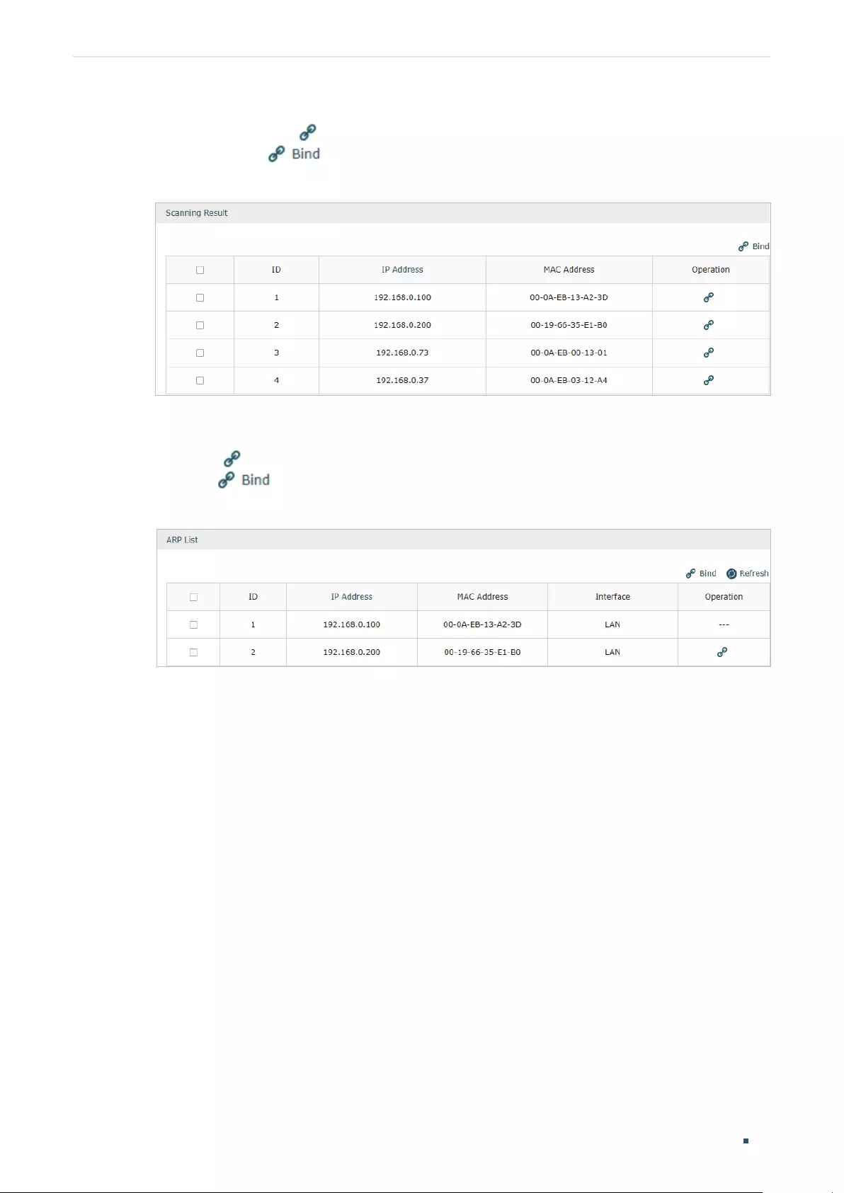
User Guide 96
Configuring Firewall Firewall Configuration
2) Wait for a moment without any operation. The scanning result will be displayed in the
following table. Click to export the entry to the IP-MAC Binding table, or select multiple
entries and click to export the entries to the IP-MAC Binding table in batch.
Figure 2-5 ARP Scanning Result
Also, you can go to Firewall > Anti ARP Spoofing > ARP List to view and bind the ARP
Scanning entries. The ARP Scanning list displays all the historical scanned entries. You
can click to export the entry to the IP-MAC Binding table, or select multiple entries
and click to export the entries to the IP-MAC Binding table in batch.
Figure 2-6 ARP List

Configuring Firewall Firewall Configuration
User Guide 97
2.1.2 Enable Anti ARP Spoofing
Choose the menu Firewall > Anti ARP Spoofing > IP-MAC Binding to load the following
page.
Figure 2-7 IP-MAC Binding-General Config
Follow the steps below to configure Anti ARP Spoofing rule:
1) In the General section, enable ARP Spoofing Defense globally. With this option enabled, the
router can protect its ARP table from being falsified by ARP spoofing packets.
2) Choose whether to enable the two sub functions.
Permit the packets matching
the IP-MAC Binding entries only
With this option enabled, when receiving a packet, the router
will check whether the IP address, MAC address and receiving
interface match any of the IP-MAC Binding entries. Only the
matched packets will be forwarded.
Send GARP packets when ARP
attack is detected
With this option enabled, the router will send GARP packets to the
hosts if it detects ARP spoofing packets on the network. The GARP
packets will inform the hosts of the correct ARP information, which
is used to replace the wrong ARP information in the hosts.
Interval If the Send GARP packets when ARP attack is detected is
enabled, configure the time interval for sending GARP packets. The
valid values are from 1 to 10000 milliseconds.
3) Click Save.
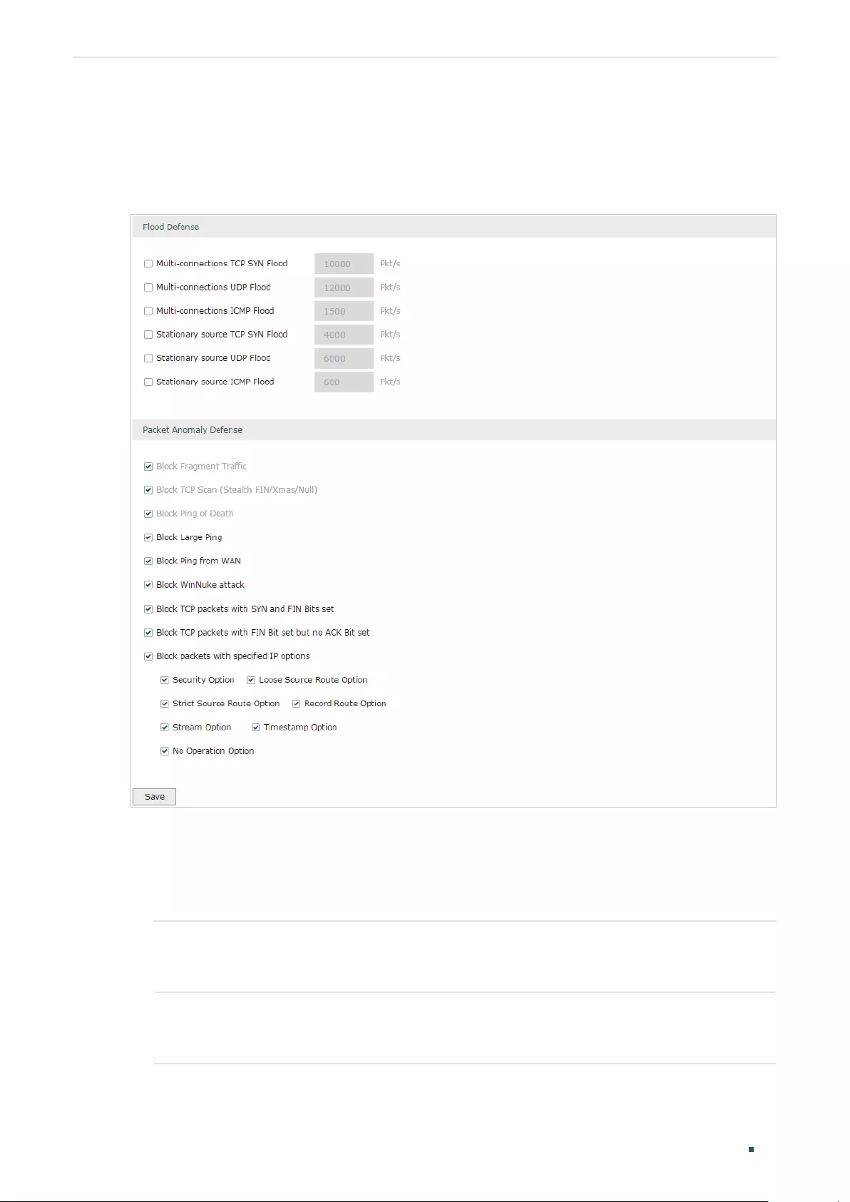
User Guide 98
Configuring Firewall Firewall Configuration
2.2 Configuring Attack Defense
Choose the menu Firewall > Attack Defense > Attack Defense to load the following page.
Figure 2-8 Attack Defense
Follow the steps below to configure Attack Defense.
1) In the Flood Defense section, check the box and configure the corresponding parameters
to enable your desired feature. By default, all the options are disabled. For details, refer to
the following table:
Multi-connections TCP
SYN Flood
With this feature enabled, the router will filter the subsequent TCP SYN
packets if the number of this kind of packets reaches the specified
threshold. The valid threshold ranges from 100 to 99999.
Multi-connections UDP
Flood
With this feature enabled, the router will filter the subsequent UDP packets
if the number of this kind of packets reaches the specified threshold. The
valid threshold ranges from 100 to 99999.

Configuring Firewall Firewall Configuration
User Guide 99
Multi-connections
ICMP Flood
With this feature enabled, the router will filter the subsequent ICMP
packets if the number of this kind of packets reaches the specified
threshold. The valid threshold ranges from 100 to 99999.
Stationary source TCP
SYN Flood
With this feature enabled, the router will filter the subsequent stationary
source TCP SYN packets if the number of this kind of packets reaches the
specified threshold. The valid threshold ranges from 100 to 99999.
Stationary source UDP
Flood
With this feature enabled, the router will filter the subsequent stationary
source UDP SYN packets if the number of this kind of packets reaches the
specified threshold. The valid threshold ranges from 100 to 99999.
Stationary source ICMP
Flood
With this feature enabled, the router will filter the subsequent stationary
source ICMP SYN packets if the number of this kind of packets reaches
the specified threshold. The valid threshold ranges from 100 to 99999.
2) In the Packet Anomaly Defense section, directly check the box to enable your desired
feature. By default, all the options are enabled. For details, refer to the following table:
Block Fragment Traffic With this option enabled, the router will filter the fragment packets.
Block TCP Scan (Stealth
FIN/Xmas/Null)
With this option enabled, the router will filter the TCP scan packets of
Stealth FIN, Xmas and Null.
Block Ping of Death With this option enabled, the router will block Ping of Death attack. Ping of
Death attack means that the attacker sends abnormal ping packets larger
than 65535 bytes to cause system crash on the target computer.
Block Large Ping With this option enabled, the router will block ping packets larger than
1024 bytes from the LAN interface to prevent Large Ping attacks. Large
Ping attack means that attackers send multiple large ping packets to
cause the system crash on the target computer.
Block Ping from WAN With this option enabled, the router will block the ICMP request from WAN.
Block WinNuke attack With this option enabled, the router will block WinNuke attacks. WinNuke
attack refers to a remote denial-of-service attack (DoS) that affects some
Windows operating systems, such as the Windows 95 and Windows N. The
attacker sends a string of OOB (Out of Band) data to the target computer
on TCP port 137, 138 or 139, causing system crash or Blue Screen of
Death.
Block TCP packets with
SYN and FIN Bits set
With this option enabled, the router will filter the TCP packets with both
SYN Bit and FIN Bit set.
Block TCP packets with
FIN Bit set but no ACK
Bit set
With this option enabled, the router will filter the TCP packets with FIN Bit
set but without ACK Bit set.
Block packets with
specified IP options
With this option enabled, the router will filter the packets with specified IP
options. You can choose the options according to your needs.
3) Click Save.
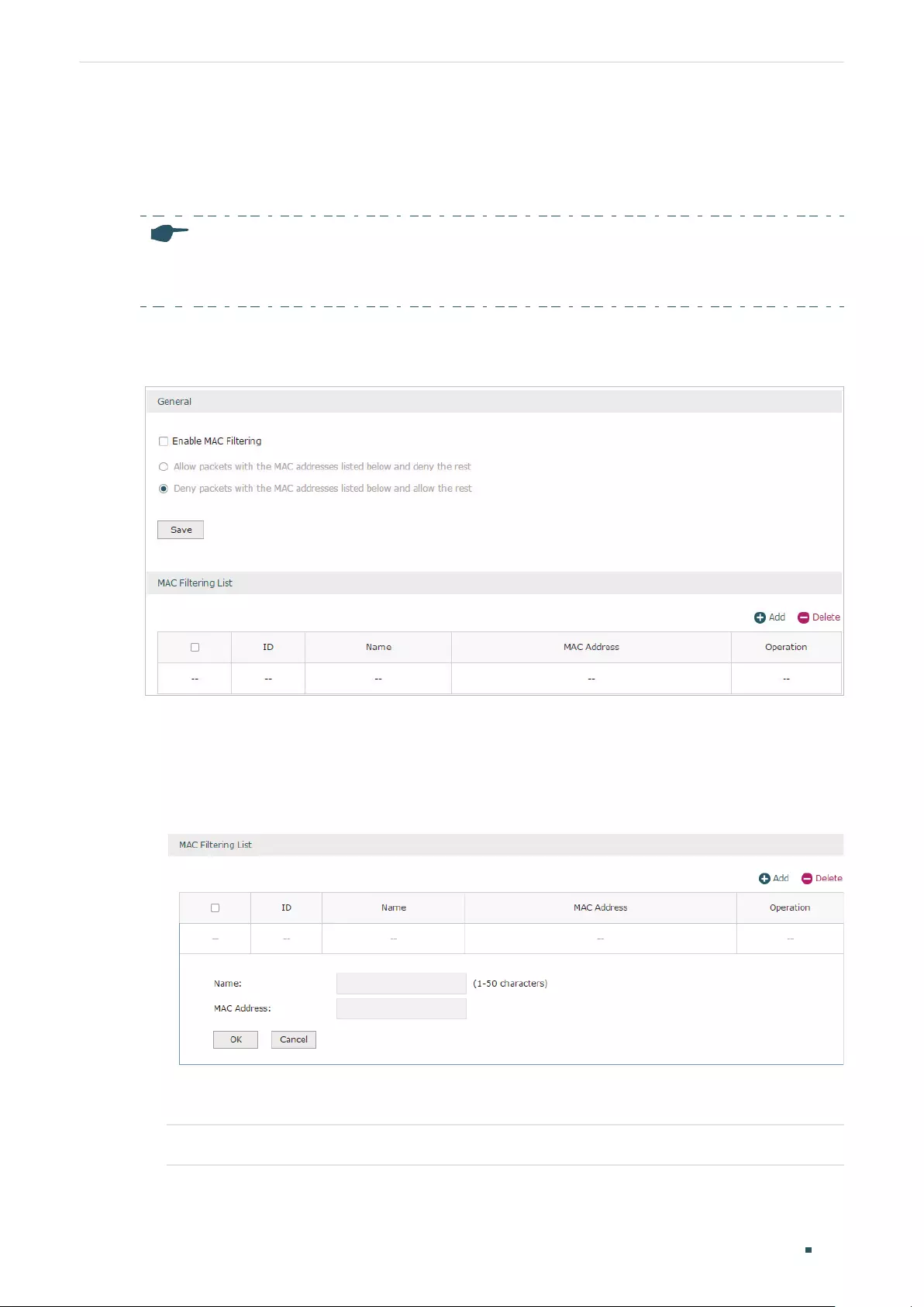
User Guide 100
Configuring Firewall Firewall Configuration
2.3 Configuring MAC Filtering
To complete MAC Filtering configuration, there are two steps. First, add MAC Filtering entries
to the MAC Filtering List. Then configure the filtering rule for these entries.
Note:
In case MAC Filtering causes access problems to the currently connected devices, it’s recommended
to add and verify the MAC Filtering entries first before configuring the filtering rule.
Choose the menu Firewall > MAC Filtering > MAC Filtering to load the following page.
Figure 2-9 MAC Filtering
Follow the steps below to configure MAC Filtering:
1) In the MAC Filtering List section, click Add to add MAC Filtering entries to the MAC Filtering
list. Specify a name and enter the MAC address in the format xx-xx-xx-xx-xx-xx. Click OK.
Figure 2-10 MAC Filtering
2) In the General section, enable MAC Filtering and select the filtering rule. Click Save, and the
filtering rule will be applied to all entries in this list.
Enable MAC Filtering Check the box to enable MAC Filtering.
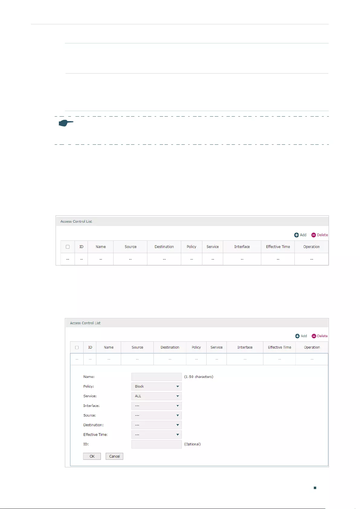
Configuring Firewall Firewall Configuration
User Guide 101
Allow packets with the
MAC addresses listed
below and deny the rest
Choose whether to select this filtering rule. With this rule selected, the
router will allow the packets with the MAC addresses in the MAC Filtering
List and deny other packets.
Deny packets with the
MAC addresses listed
below and allow the
rest
Choose whether to select this filtering rule. With this rule selected, the
router will deny the packets with the MAC addresses in the MAC Filtering
List and allow other packets.
Note:
MAC Filtering rules take effect on the LAN interface instead of the WAN interface.
2.4 Configuring Access Control
Choose the menu Firewall > Access Control > Access Control and click Add to load the
following page.
Figure 2-11 Access Control
This table displays the Access Control entries. Follow the steps below to add a new Access
Control entry.
1) Click Add and the following page will appear.
Figure 2-12 Access Control

User Guide 102
Configuring Firewall Firewall Configuration
2) Configure the required parameters and click OK:
Name Specify a name for the rule. It can be 50 characters at most. The name of
each entry cannot be repeated.
Policy Select whether to block or allow the packets matching the rule to access the
network.
Service Select the effective service for the rule. The service referenced here can be
created on the Preferences > Service Type page.
Interface Select the effective interface for the rule.
Source Select an IP group to specify the source address range for the rule. The IP
group referenced here can be created on the Preferences > IP Group page.
Destination Select an IP group to specify the destination address range for the rule. The
IP group referenced here can be created on the Preferences > IP Group
page.
Effective Time Select the effective time for the rule. The effective time referenced here can
be created on the Preferences > Time Range page.
ID Specify a rule ID. A smaller ID means a higher priority. This value is optional,
and the newly added rule without this value configured will get the largest ID
among all rules, which means the newly added rule has the lowest priority.
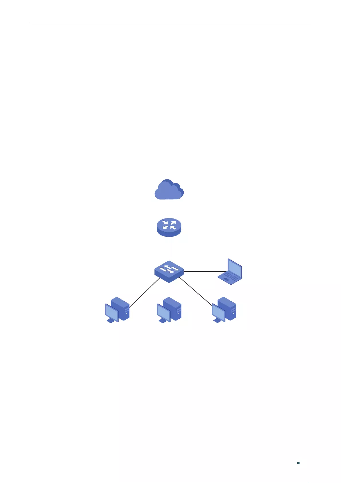
Configuring Firewall Configuration Examples
User Guide 103
3 Configuration Examples
3.1 Example for Anti ARP Spoofing
3.1.1 Network Requirements
In the diagram below, several hosts are connected to the network via a layer 2 switch, and the
router is the gateway of this network. Since there exists the possibility that the attacker will
launch a series of ARP attacks, it is required to configure the router to protect itself and the
terminal hosts from the ARP attacks.
Figure 3-1 Network Topology
Internet
Layer 2 Switch
Host A
192.168.0.10
00-19-56-8A-4C-71
Host B
192.168.0.20
00-19-56-82-3B-70
Host C
192.168.0.30
00-19-56-8D-22-75
Attacker
Gateway
LAN
192.168.0.1
WAN
3.1.2 Configuration Scheme
The attacker can launch three types of ARP attacks: cheating gateway, imitating gateway
and cheating terminal hosts. The following section introduces the three ARP attacks and the
corresponding solutions.
Cheating Gateway
Cheating gateway attack is aimed at the router.

User Guide 104
Configuring Firewall Configuration Examples
The attacker pretends to be legal terminal hosts and sends fake ARP packets to the router,
cheating the router into recording wrong ARP maps of the hosts. As a result, packets from the
gateway cannot be correctly sent to the hosts. To protect the router from this kind of attack,
you can configure Anti ARP Spoofing on the router.
Imitating Gateway and Cheating Hosts
These two attacks are aimed at the terminal hosts.
Imitating Gateway means that the attacker imitates the gateway and sends fake ARP packets
to the hosts. As a result, the hosts record wrong ARP map of the gateway and cannot send
packets to the router correctly.
Cheating Hosts means that the attacker pretends to be a legal host and sends fake ARP
packets to other hosts. As a result, the cheated hosts record an incorrect ARP map of the legal
host and cannot send packets to legal host correctly.
To protect the hosts from the attacks above, it is recommend to take both of the precautions
below.
»Configure the firewall feature on the hosts.
»Configure the router to send GARP packets to the hosts when the router detects ARP
attacks. The GARP packets will inform the hosts of the correct ARP maps, and the wrong
ARP maps in the hosts will be replaced by the correct ones.
In conclusion, to protect the network from ARP attacks, we should make sure both the router
and the hosts are configured with the relevant ARP defense features. Here we introduce how to
configure Anti ARP Spoofing on the router. There are mainly three steps:
1) Get the IP and MAC addresses of the legal hosts and bind them to the IP-MAC Binding list.
2) Enable Anti ARP Spoofing.
3) Configure the router to send GARP packets when ARP attacks are detected.
3.1.3 Configuration Procedure
Follow the steps below to configure Anti ARP Spoofing on the router:
1) Choose the menu Firewall > Anti ARP Spoofing > IP-MAC Binding to load the following
page. In the IP-MAC Binding List section, click Add.
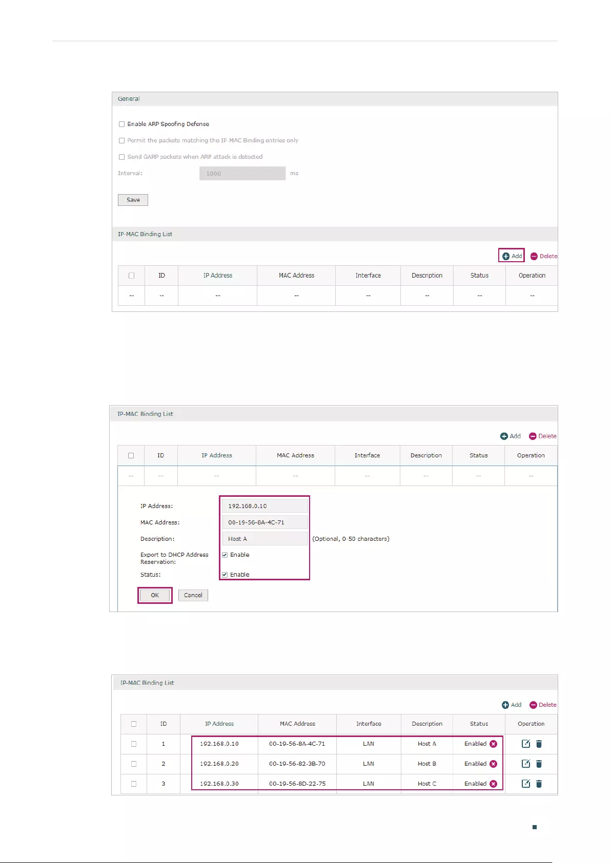
Configuring Firewall Configuration Examples
User Guide 105
Figure 3-2 Anti ARP Spoofing Page
2) The following page will appear. Enter the IP address and MAC address of Host A, and give
a description “Host A” for this entry. Since the IP address 192.168.0.10 has been used by
Host A, we keep Export to DHCP Address Reservation as “Enable» to preserve this IP
address from being assigned to other hosts. Keep Status of this entry as “Enable”. Click OK.
Figure 3-3 Add IP-MAC Binding Entry
3) Add the IP-MAC Binding entries for Host B and Host C as introduced above, and verify your
configurations.
Figure 3-4 Verify IP-MAC Binding Entires

User Guide 106
Configuring Firewall Configuration Examples
4) In the General section on the same page, check the boxes to enable ARP Spoofing
Defense and Send GARP packets when ARP attack is detected, and keep the interval as
1000 milliseconds. Click Save.
Figure 3-5 Configure Anti ARP Spoofing
3.2 Example for MAC Filtering
3.2.1 Network Requirements
In the diagram below, the router is the gateway of the network. The network administrator now
detects some abnormal attack packets from a host whose MAC address is 00:17:87:4A:5C:25.
To protect the devices from being attacked, it is required that all packets from the attacker
should be dropped when passing through the router.
Figure 3-6 Network Topology
Layer 2 Switch Attacker
00:17:87:4A:5C:25
Gateway
LAN LAN
WAN
Internet
3.2.2 Configuration Scheme
To meet this requirement, we can configure MAC Filtering on the router to filter the packets
with the MAC address of the attacker. The configuration overview is as follows:
1) Enable MAC Filtering globally and select the filtering rule as “Deny packets with the MAC
addresses listed below and allow the rest“.
2) Add the MAC address of the attacker to the MAC Filtering List.
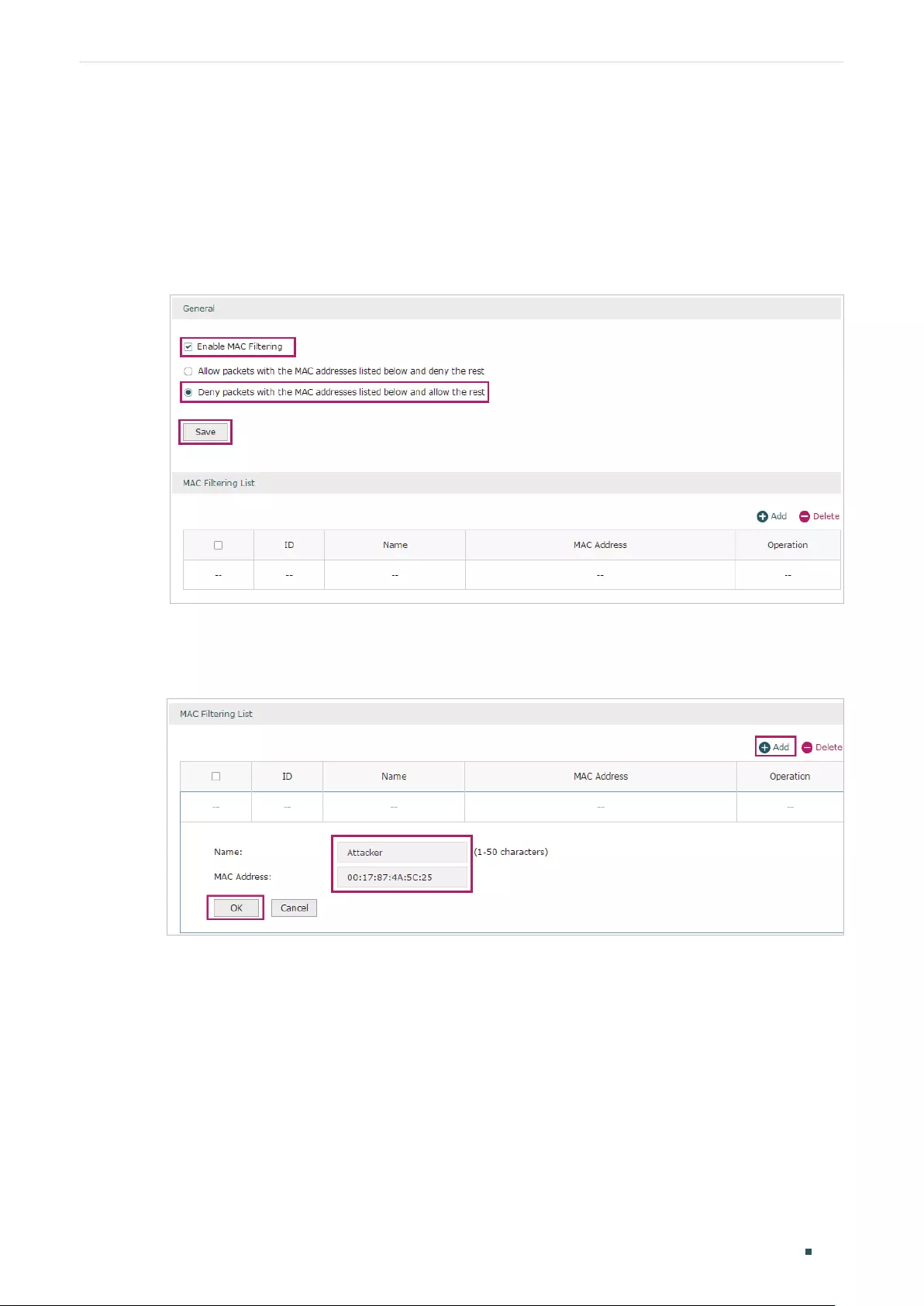
Configuring Firewall Configuration Examples
User Guide 107
3.2.3 Configuration Procedure
Follow the steps below to configure MAC Filtering on the router:
1) Choose the menu Firewall > MAC Filtering > MAC Filtering to load the following page. In
the General section, enable MAC Filtering and select the filtering rule as “Deny packets with
the MAC addresses listed below and allow the rest“. Click Save.
Figure 3-7 Enable MAC Filtering
2) In the MAC Filtering List section, click Add. Specify a name for this entry and enter the
attacker’s MAC address. Click OK.
Figure 3-8 Add MAC Filtering Entry
3.3 Example for Access Control
3.3.1 Network Requirements
In the diagram below, the R&D and some other departments are connected to a layer 2 switch
and access the internet via the router. To limit the acts of the R&D department users, such as

User Guide 108
Configuring Firewall Configuration Examples
sending emails with the exterior mailbox, it is required that the R&D users can only visit websites
via HTTP and HTTPs on the internet at any time. For other departments, there is no limitation.
Figure 3-9 Network Topology
Layer 2 Switch
Router
LAN
192.168.0.1/24
WAN
1.1.1.2
Internet
R&D Department
192.168.0.10/24-192.168.0.120/24 Other Departments
3.3.2 Configuration Scheme
To meet these requirements, we can configure Access Control rules on the router to filter
the specific types of packets from R&D department: only the HTTP and HTTPs packets are
allowed to be sent to the internet, and other types of packets are not allowed. The configuration
overview is as follows:
1) Add an IP group for the R&D department in the Preferences module.
2) By default, the HTTP service type already exists, and you need to add HTTPs to the Service
Type list in the Preferences module.
3) Create two rules to allow the HTTP and HTTPs packets from the R&D department to be sent
to the WAN.
4) Since visiting the internet needs DNS service, add a rule to allow the DNS packets to be sent
to the WAN. DNS service is already in the Service Type list by default.
5) Create a rule to block all packets from the R&D department to the WAN. This rule should
have the lowest priority among all the rules.
Configuring Firewall Configuration Examples
User Guide 109
3.3.3 Configuration Procedure
Follow the steps below to complete the configuration:
1) Choose the menu Preferences > IP Group > IP Address to load the configuration page, and
click Add. Specify a name RD, select IP Address Range and enter the IP address range of
the R&D department. Click OK.
Figure 3-10 Configure IP Address Range
2) Choose the menu Preferences > IP Group > IP Group to load the configuration page, and
click Add. Specify a group name “RD_Dept”, select the preset address range «RD” and click
OK.
Figure 3-11 Configure IP Group
3) Choose the menu Preferences > Service Type > Service Type to load the configuration
page, and click Add. Specify the service type name as “HTTPS”, select the protocol as “TCP”,
specify the source port range as “0-65535” and destination port range as “443-443”, and
click OK.

User Guide 110
Configuring Firewall Configuration Examples
Figure 3-12 Configure HTTPS Service Type
4) Choose the menu Firewall > Access Control > Access Control to load the configuration
page, and click Add. Specify a name for this rule. Select “Allow” as the rule policy, “HTTP”
as the service type, “LAN” as the effective interface, “RD_Dept” as the source IP group,
“IPGROUP_ANY” as the destination IP group, and “Any” as the effective time. Click OK.
This rule means that all the HTTP packets from the R&D department are allowed to be
transmitted from LAN to the internet at any time.
Figure 3-13 Configure Allow Rule for HTTP Service
5) Choose the menu Firewall > Access Control > Access Control to load the configuration
page, and click Add. Specify a name for this rule. Select “Allow” as the rule policy, “HTTPS”
as the service type, “LAN” as the effective interface, “RD_Dept” as the source IP group,
“IPGROUP_ANY” as the destination IP group, and “Any” as the effective time. Click OK.
This rule means that all the HTTPS packets from the R&D department are allowed to be
sent from the LAN to the internet at any time.
Configuring Firewall Configuration Examples
User Guide 111
Figure 3-14 Configure Allow Rule for HTTPS Service
6) Choose the menu Firewall > Access Control > Access Control to load the configuration
page, and click Add. Specify a name for this rule. Select “Allow” as the rule policy, “DNS”
as the service type, “LAN” as the effective interface, “RD_Dept” as the source IP group,
“IPGROUP_ANY” as the destination IP group, and “Any” as the effective time. Click OK.
This rule means that all DNS packets from the R&D department are allowed to be sent
from the LAN to the internet at any time.
Figure 3-15 Configure Allow Rule for DNS Service
7) Choose the menu Firewall > Access Control > Access Control to load the configuration
page, and click Add. Specify a name for this rule. Select “Block” as the rule policy, “ALL”
as the service type, “LAN” as the effective interface, “RD_Dept” as the source IP group,
“IPGROUP_ANY” as the destination IP group, and “Any” as the effective time. Click OK.
User Guide 112
Configuring Firewall Configuration Examples
This rule means that all packets from the R&D department are blocked from being sent
from the LAN to the internet at all times.
Figure 3-16 Configure Block Rule for ALL Services
 Verify your configuration result. In the Access Control List, the rule with a smaller ID has a
higher priority. Since the router matches the rules beginning with the highest priority, make
sure the three Allow rules have the smaller ID numbers compared with the Block rule. In this
way, the router checks whether the received packet matches the three Allow rules first, and
only packets that do not match any of the Allow rules will be blocked.
Figure 3-17 Verify Configuration Result

Part 7
Configuring
Behavior Control
CHAPTERS
1. Behavior Control
2. Behavior Control Configuration
3. Configuration Examples

User Guide 114
Configuring Behavior Control Behavior Control
1 Behavior Control
1.1 Overview
With the Behavior Control feature, you can control the online behavior of local hosts. You can
block specific hosts’ access to specific websites using URLs or keywords, block HTTP posts
and prevent certain types of files from being downloaded from the internet.
1.2 Supported Features
The Behavior Control module supports two features: Web Filtering and Web Security.
Web Filtering
Web Filtering is used to filter specific websites. The router provides two ways to filter websites:
Web Group Filtering and URL Filtering.
Web Group Filtering: You can configure multiple websites as a web group, and set a filtering
rule for the group. More than one group can be created and several groups can share a
same filtering rule.
URL Filtering: You can directly set a filtering rule for specific entire URLs or keywords.
Web Security
Web Security is used to control the specific online behaviors of local users. You can configure
this feature to block HTTP post, which means that the local users cannot log in, submit
comments or perform any other operation which needs HTTP post. Also, you can prohibit local
users from downloading specific types of files from the internet.
Configuring Behavior Control Behavior Control Configuration
User Guide 115
2 Behavior Control Configuration
In Behavior Control module, you can configure the following features:
Web Filtering
Web Security
2.1 Configuring Web Filtering
There are two methods to filter websites: Web Group Filtering and URL Filtering.
2.1.1 Configure Web Group Filtering
To configure Web Group Filtering, add one or more web groups first, and then add web group
filtering entries using the created groups.
Add Web Groups
Choose the menu Behavior Control> Web Filtering > Web Group and click Add to load
the following page.
Figure 2-1 Web Group Page
Configure the following parameters and click OK.

User Guide 116
Configuring Behavior Control Behavior Control Configuration
Name Specify a name for the group. The name of each group cannot be repeated.
Member Add one or more website members to the group. The format of the website
members is “www.tp-link.com” or “*.tp-link.com”, in which “*” is a wildcard. Use
Enter key, Space key, “,” or “;” to divide different websites.
File Path Import member list in your TXT file from your host. The format is “www.tp-link.
com” or “*.tp-link.com”, in which “*” is a wildcard. Use Enter key, Space key, “,”
or “;” to divide different websites.
Description Enter a brief description for the group.
Add Web Group Filtering Entries
Before configuring web group entries, go to the Preferences module to configure the IP
Group and Effective Time according to your needs.
Choose the menu Behavior Control > Web Filtering > Web Group Filtering and click Add
to load the following page.
Figure 2-2 Web Group Filtering Page
Follow the steps below to add Web group filtering entries:
1) In the Web Filtering List section, configure the required parameters and click OK.
IP Group Select an IP group for the rule. The IP group referenced here can
be created on the Preferences > IP Group page.

Configuring Behavior Control Behavior Control Configuration
User Guide 117
Policy Choose to allow or deny the websites that are in the selected web
group(s).
Web Group Select one or more web groups. The web group referenced here
can be created on the Behavior Control > Web Filtering > Web
Group page.
Effective Time Select the effective time. The effective time referenced here can
be created on the Preferences > Time Range page.
Description Enter a brief description for the group.
ID Specify a rule ID. A smaller ID means a higher priority. This value
is optional. A newly added rule with this field left blank will get the
largest ID among all rules, which means that the newly added rule
has the lowest priority.
Status Check the box to enable the rule.
2) In the General section, enable Web Filtering. Click Save.

User Guide 118
Configuring Behavior Control Behavior Control Configuration
2.1.2 Configuring URL Filtering
Before configuring URL Filtering, go to the Preferences module to configure the IP Group
and Effective Time according to your needs.
Choose the menu Behavior Control > Web Filtering > URL Filtering and click Add to load
the following page.
Figure 2-3 URL Filtering Page
Follow the steps below to configure URL filtering:
1) In the URL Filtering List section, click Add and configure the required parameters. Click OK.
IP Group Select an IP group for the rule. The IP group referenced here can
be created on the Preferences > IP Group page.
Policy Choose to allow or deny the websites that match the filtering
content.

Configuring Behavior Control Behavior Control Configuration
User Guide 119
Mode Select the filtering mode.
Keywords: If a website address contains any of the keywords, the
policy will be applied to this website.
URL Path: If a website address is the same as any of the entire
URLs, the policy will be applied to this website.
Filtering Content Add filtering contents. Use the Enter key, Space key, “,” or “;” to
divide different filtering contents.
“.” means that this rule will be applied to any website. For example,
if you want to allow website A and deny other websites, you can
add an Allow rule with the filtering content “A” and add a Deny
rule with the filtering content “.”. Note that “.” rule should have the
largest ID number, which means that it has the lowest priority.
Effective Time Select the effective time. The effective time referenced here can
be created on the Preferences > Time Range page.
Status Check the box to enable the rule.
Description Enter a brief description for the group.
ID Specify a rule ID. A smaller ID means a higher priority. This value
is optional. The newly added rule without this value configured
will get the largest ID among all rules, which means that the newly
added rule has the lowest priority.
2) In the General section, enable URL filtering. Click Save.

User Guide 120
Configuring Behavior Control Behavior Control Configuration
2.2 Configuring Web Security
Before configuring Web Security, go to Preferences module to configure the IP Group and
Effective Time according to your needs.
Choose the menu Behavior Control > Web Security > Web Security and click Add to load
the following page.
Figure 2-4 Web Security Page
Follow the steps below to configure Web Security.
1) In the Web Security List section, configure the following parameters and click OK to add a
Web Security rule.
IP Group Select an IP group for the rule. The IP group referenced here can be
created on the Preferences > IP Group page.
Block HTTP Post With this option enabled, HTTP posts will be blocked. The hosts of the
selected IP group cannot log in, submit comments or do any operation
using HTTP post.

Configuring Behavior Control Behavior Control Configuration
User Guide 121
File Suffix Enter file suffixes to specify the file types. Use Enter key, Space key, “,” or “;”
to divide different file suffixes. The hosts of the selected IP group cannot
download these types of files from the internet.
Effective Select the effective time. The effective time referenced here can be
created on the Preferences > Time Range page.
Description Enter a brief description for the group.
Status Check the box to enable the rule.
2) In the General section, enable Web Security and click Save.

User Guide 122
Configuring Behavior Control Configuration Examples
3 Configuration Examples
3.1 Example for Access Control
3.1.1 Network Requirements
In the diagram below, the R&D and some other departments are connected to a layer 2 switch
and access the internet via the router. For data security purposes, it is required that the R&D
department users can only visit the official website of the company, for example: http://www.tp-
link.com. For other departments, there is no limitation of website access.
Figure 3-1 Network Topology
R
Layer 2 Switch
Router
LAN
192.168.0.1/24
WAN
1.1.1.2
Internet
R&D Department
192.168.0.10/24-192.168.0.120/24 Other Departments
3.1.2 Configuration Scheme
We can configure Web Filtering to limit the website access of the specific hosts. Both Web
Group Filtering and URL Filtering can achieve this. In this example, the configuration difference
between Web Group Filtering and URL Filtering is as follows:

Configuring Behavior Control Configuration Examples
User Guide 123
In Web Group Filtering, you need to add the official website address to a web group before
configuring the filtering rule.
In URL Filtering, you can directly specify the official website address in the filtering rule.
Here we take Web Group Filtering as an example. The configuration overview is as follows:
1) Add an IP group for the R&D department in the Preferences module.
2) Create a web group with the group member www.tp-link.com.
3) Add a Whitelist rule to allow the R&D department users to access www.tp-link.com.
4) Add a Blacklist rule to forbid the R&D department users from accessing all websites. Note
that the priority of this rule should be lower than the Whitelist rule.
3.1.3 Configuration Procedure
Follow the steps below to complete the configuration:
1) Choose the menu Preferences > IP Group > IP Address to load the configuration page, and
click Add. Specify a name “RD”, select IP Address Range and enter the IP address range of
the R&D department. Click OK.
Figure 3-2 Configure IP Address Range
2) Choose the menu Preferences > IP Group > IP Group to load the configuration page, and
click Add. Specify a group name “RD_Dept”, select the preset address range «RD» and click
OK.

User Guide 124
Configuring Behavior Control Configuration Examples
Figure 3-3 Configure IP Group
3) Choose the menu Behavior Control > Web Filtering > Web Group to load the configuration
page, and click Add. Specify a name “RD_Filtering” for this web group and add the member
“www.tp-link.com”. Click OK.
Figure 3-4 Configure Web Group
4) Choose the menu Behavior Control > Web Filtering > Web Group Filtering to load the
configuration page, and click Add. Select “RD_Dept” as the IP Group, “Whitelist” as the
Policy, “RD_Filtering“ as the Web Group, and “Any” as the Effective Time. Click OK.
This rule means that the hosts in the R&D department are allowed to access the website
www.tp-link.com at any time.
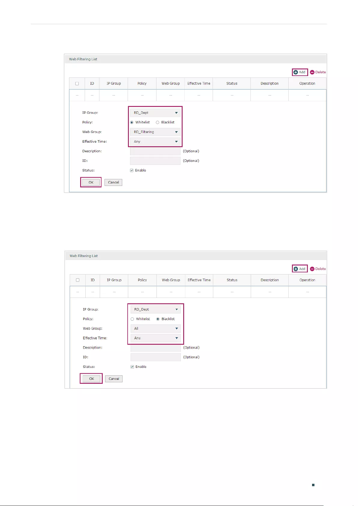
Configuring Behavior Control Configuration Examples
User Guide 125
Figure 3-5 Configure Whitelist Rule
5) On the same page, click Add. Select “RD_Dept” as the IP Group, “Blacklist” as the Policy, “All”
as the Web Group, and “Any” as the Effective Time. Click OK.
This rule means that the hosts in the R&D department are denied access to all websites
at all times.
Figure 3-6 Configure Blacklist Rule
6) On the same page, verify your configurations. In the Web Filtering List, the rule with a smaller
ID has a higher priority. Since the router matches the rules beginning with the highest
priority, make sure the Whitelist rule has the smaller ID number. In this way, the router allows
the hosts to access the Whitelist website and denies them to access others.

User Guide 126
Configuring Behavior Control Configuration Examples
Figure 3-7 Verify Configuration Result
7) In the General section on the same page, enable Web Filtering globally and click Save.
Figure 3-8 Enable Web Filtering
3.2 Example for Web Security
3.2.1 Network Requirements
In the diagram below, the company’s hosts are connected to a layer 2 switch and access the
internet via the router. For security reasons, it is required that the users in the LAN cannot log
in, submit comments or download rar files on the internet.
Figure 3-9 Network Topology
Internet
R
Layer 2 Switch
Router
LAN
……
WAN

Configuring Behavior Control Configuration Examples
User Guide 127
3.2.2 Configuration Scheme
We can configure Web Security to meet these requirements. To block behaviors such as
login and comment submitting, we can configure the router to block HTTP post; to block
downloading of rar files, we can specify the suffix “rar” in the file suffix column.
3.2.3 Configuration Procedure
Follow the steps below to complete the configuration:
1) Choose the menu Behavior Control > Web Security > Web Security and click Add to load
the following page. Select “IPGROUP_LAN” as the IP Group, enable Block HTTP Post, enter
“rar” in the File Suffix filed, select “Any” as the Effective Time, and keep the Status as
“Enable”. Click OK.
Figure 3-10 Configure Web Security Entry
2) In the General section on the same page, enable Web Security and click Save.
Figure 3-11 Enable Web Security

Part 8
Configuring VPN
CHAPTERS
1. VPN
2. IPSec VPN Configuration
3. L2TP Configuration
4. PPTP Configuration
5. Configuration Examples

Configuring VPN VPN
User Guide 129
1 VPN
1.1 Overview
VPN (Virtual Private Network) provides a means for secure communication between
remote computers across a public wide area network (WAN), such as the internet. Virtual
indicates the VPN connection is based on the logical end-to-end connection instead of the
physical end-to-end connection. Private indicates users can establish the VPN connection
according to their requirements and only specific users are allowed to use the VPN
connection.
The core of VPN is to realize tunnel communication, which fulfills the task of data
encapsulation, data transmission and data decompression via the tunneling protocol.
Common tunneling protocols are Layer 2 tunneling protocol and Layer 3 tunneling
protocol.
Figure 1-1 Typical Topology of VPN
Remote Client
Gateway (Client)
Enterprise Server
Gateway (Server)
Internet
VPN Tunnel
1.2 Supported Features
The router supports Layer 2 tunneling protocol (PPTP, L2TP) and Layer 3 tunneling
protocol (IPSec).
PPTP
PPTP (Point-to-Point Tunneling Protocol) is a network protocol that enables the secure
transfer of data from a remote client to a private enterprise server by creating a VPN
across TCP/IP-based data networks. PPTP supports on-demand, multiprotocol, virtual
private networking over public networks, such as the internet.
L2TP
L2TP (Layer 2 Tunneling Protocol) provides a way for a dialup user to make a virtual Point-
to-Point Protocol (PPP) connection to an L2TP network server (LNS), which can be a
security gateway. L2TP sends PPP frames through a tunnel between an L2TP access
concentrator (LAC) and the LNS. Because of the lack of confidentiality inherent in the L2TP
protocol, it is often implemented along with IPSec.

User Guide 130
Configuring VPN VPN
IPSec
IPSec (IP Security) can provide security services such as data confidentiality, data integrity
and data authentication at the IP layer. IPSec uses IKE (Internet Key Exchange) to handle
negotiation of protocols and algorithms based on the user-specified policy, and to
generate the encryption and authentication keys to be used by IPSec. IPSec can be used
to protect one or more paths between a pair of hosts, between a pair of security gateways,
or between a security gateway and a host. The security gateway refers to a device which
implements IPSec protocol. For example, a router or a firewall implementing IPSec is a
security gateway.

Configuring VPN IPSec VPN Configuration
User Guide 131
2 IPSec VPN Configuration
To complete the IPSec VPN configuration, follow these steps:
1) Configure the IPSec Policy.
2) Verify the connectivity of the IPSec VPN tunnel.
Configuration Guidelines
For both ends of the VPN tunnel, the Pre-shared key, Proposal, Exchange Mode, and
Encapsulation Mode should be identical.
For both ends of the VPN tunnel, the Remote Gateway, Local/Remote Subnet, Local/
Remote ID Type should be matched.
2.1 Configuring the IPSec Policy
2.1.1 Configuring the Basic Parameters
Choose the menu VPN > IPSec > IPSec Policy and click Add to load the following page.
Figure 2-1 Configuring the Basic Parameters
Follow these steps to configure the basic parameters:
1) Specify the name of the IPSec Policy.
2) Configure the Network Mode. Select LAN-to-LAN when the network is connected to
the other network. Select Client-to-LAN when a host is connected to the network.
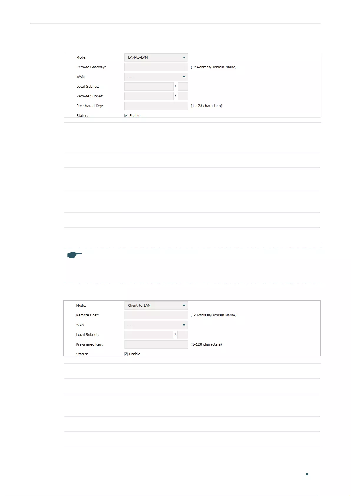
User Guide 132
Configuring VPN IPSec VPN Configuration
When the LAN-to-LAN mode is selected, the following section will appear.
Remote
Gateway
Enter an IP address or a domain name (1 to 255 characters) as the remote
gateway. 0.0.0.0 represents any IP address. Only when the negotiation mode is
set to Responder Mode can you enter 0.0.0.0.
WAN Specify the WAN port on which the IPSec tunnel is established.
Local Subnet Specify the local network. (It’s always the IP address range of LAN on the local
side of the VPN tunnel.) It’s formed from the IP address and subnet mask.
Remote Subnet Specify the remote network. (It’s always the IP address range of LAN on the
remote peer of the VPN tunnel.) It’s formed from the IP address and subnet mask.
Pre-shared Key Specify the unique pre-shared key for both peers’ authentication.
Status Choose to enable the IPSec policy.
Note:
The Local Subnet and Remote Subnet should not be in the same network segment when
choosing LAN-to-LAN as the VPN mode.
When the Client-to-LAN mode is selected, the following section will appear.
Remote Host Enter the IP address of the remote host. 0.0.0.0 represents any IP address.
WAN Specify the WAN port on which the IPSec tunnel is established.
Local Subnet Specify the local network. (This is the IP address range of the LAN on the local
side of the VPN tunnel.) It’s formed from the IP address and subnet mask.
Pre-shared Key Specify the unique pre-shared key for both peers’ authentication.
Status Choose to enable the IPSec policy.
3) Click OK.
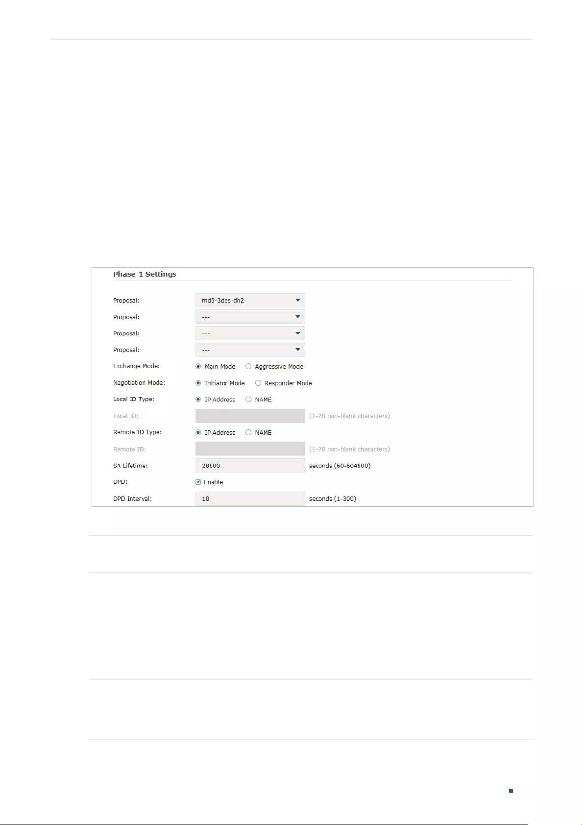
Configuring VPN IPSec VPN Configuration
User Guide 133
2.1.2 Configuring the Advanced Parameters
Advanced settings include IKEv1 phase-1 settings and IKEv1 phase-2 settings. IKEv1
phase-1 is used to authenticate both sides of the communication and establish the IKE
SA. IKEv1 phase-2 is used to negotiate about keys and security related parameters, then
establish the IPSec SA. It is suggested to keep the default advanced settings. You can
complete the configurations according to your actual needs.
Configuring the IKE Phase-1 Parameters
Choose the menu VPN > IPSec > IPSec Policy and click Advanced Settings to load the
following page.
Figure 2-2 Configuring the IKE Phase-1 Parameters
In the Phase-1 Settings section, configure the IKE phase-1 parameters and click OK.
Proposal Select the proposal for IKE negotiation phase 1 to specify the encryption algorithm,
authentication algorithm and DH group. Up to four proposals can be selected.
Exchange
Mode
Specify the IKE Exchange Mode as Main Mode or Aggressive Mode. By default, it is
Main Mode.
Main Mode: Main mode provides identity protection and exchanges more information,
which applies to scenarios with higher requirements for identity protection.
Aggressive Mode: Aggressive Mode establishes a faster connection but with lower
security, which applies to scenarios with lower requirements for identity protection.
Negotiation
Mode
Specify the IKE Negotiation Mode as Initiator Mode or Responder Mode. Initiator Mode
means that the local device initiates a connection to the peer. Responder Mode means
that the local device waits for the connection request initiated by the peer. You can
keep this parameter as default.

User Guide 134
Configuring VPN IPSec VPN Configuration
Local ID Type Specify the local ID type for IKE negotiation.
IP Address: Use an IP address as the ID in IKE negotiation. It is the default type.
NAME: Use a name as the ID in IKE negotiation. It refers to FQDN (Fully Qualified
Domain Name).
Local ID When the Local ID Type is configured as NAME, enter a name for the local device as
the ID in IKE negotiation.
Remote ID
Type
Specify the remote ID type for IKE negotiation.
IP Address: Use an IP address as the ID in IKE negotiation. It is the default type.
NAME: Use a name as the ID in IKE negotiation. It refers to FQDN (Fully Qualified
Domain Name).
Remote ID When the Remote ID Type is configured as NAME, enter a name of the remote peer as
the ID in IKE negotiation .
SA Lifetime Specify ISAKMP SA (Security Association) Lifetime in IKE negotiation. If the SA lifetime
expired, the related ISAKMP SA will be deleted.
DPD Check the box to enable or disable DPD (Dead Peer Detect) function. If enabled, the IKE
endpoint can send a DPD request to the peer to inspect whether the IKE peer is alive.
DPD Interval If DPD is triggered, specify the interval between sending DPD requests. If the IKE
endpoint receives a response from the peer during this interval, it considers the peer
alive. If the IKE endpoint does not receive a response during the interval, it considers
the peer dead and deletes the SA.
Configuring the IKE Phase-2 Parameters
Choose the menu VPN > IPSec > IPSec Policy and click Advanced Settings to load the
following page.
Figure 2-3 Configuring the IKE Phase-2 Parameters
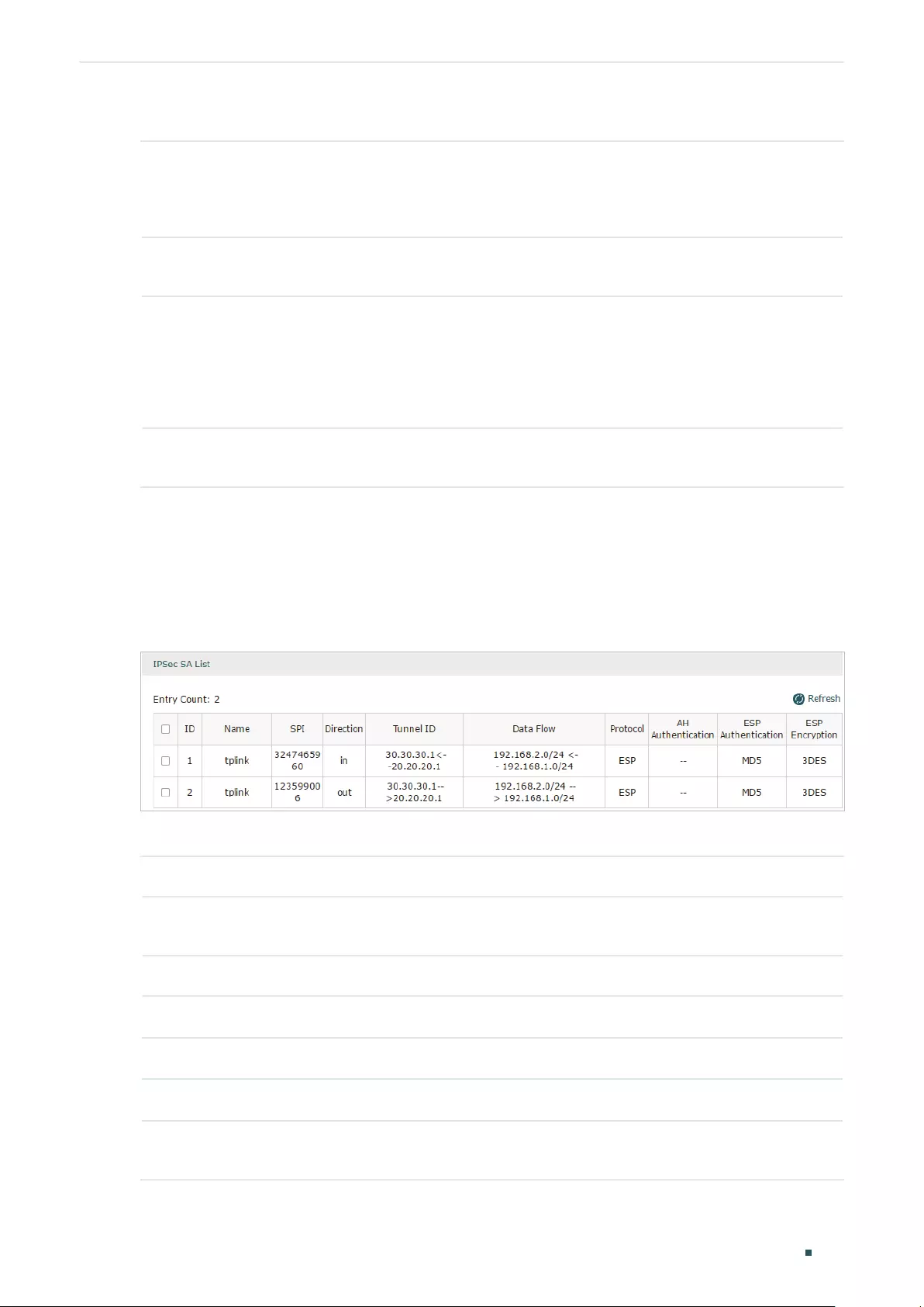
Configuring VPN IPSec VPN Configuration
User Guide 135
In the Phase-2 Settings section, configure the IKE phase-2 parameters and click OK.
Encapsulation
Mode
Specify the Encapsulation Mode as Tunnel Mode or Transport Mode. When both
ends of the tunnel are hosts, either mode can be chosen. When at least one of the
endpoints of a tunnel is a security gateway, such as a router or firewall, tunnel mode is
recommended to ensure safety.
Proposal Select the proposal for IKE negotiation phase 2 to specify the encryption algorithm,
authentication algorithm and protocol. Up to four proposals can be selected.
PFS Select the DH group to enable PFS (Perfect Forward Security) for IKE mode, then the
key generated in phase 2 will be irrelevant with the key in phase 1, which enhance the
network security.
If you select None, it means PFS is disabled and the key in phase 2 will be generated
based on the key in phase 1.
SA Lifetime Specify IPSec SA (Security Association) Lifetime in IKE negotiation. If the SA lifetime
expired, the related IPSec SA will be deleted.
2.2 Verifying the Connectivity of the IPSec VPN tunnel
Choose the menu VPN > IPSec > IPSec SA to load the following page.
Figure 2-4 IPSec SA List
The IPSec SA List shows the information of the established IPSec VPN tunnel.
Name Displays the name of the IPSec policy associated with the SA.
SPI Displays the SPI (Security Parameter Index) of the SA, including outgoing SPI and
incoming SPI. The SPI of each SA is unique.
Direction Displays the direction (in: incoming/out: outgoing) of the SA.
Tunnel ID Displays the IP addresses of the local and remote peers.
Data Flow Displays the Local Subnet and Remote Subnet/host covered by the SA.
Protocol Displays the authentication protocol and encryption protocol used by the SA.
AH
Authentication
Displays the AH authentication algorithm used by the SA.

User Guide 136
Configuring VPN IPSec VPN Configuration
ESP
Authentication
Displays the ESP authentication algorithm used by the SA.
ESP Encryption Displays the ESP encryption algorithm used by the SA.

Configuring VPN L2TP Configuration
User Guide 137
3 L2TP Configuration
To complete the L2TP configuration, follow these steps:
1) Configure the VPN IP pool.
2) Configure L2TP globally.
3) Configure the L2TP server/client.
4) (Optional) Configure the L2TP users.
5) Verify the connectivity of the L2TP VPN tunnel.
Configuration Guidelines
When the network mode is configured as Client-to-LAN and the router acts as the L2TP
server, you don’t need to configure the L2TP client on the router.
When the network mode is configured as LAN-to-LAN and the router acts as the L2TP
client gateway, you don’t need to configure the L2TP users on the router.
3.1 Configuring the VPN IP Pool
Choose the menu Preferences> VPN IP Pool > VPN IP Pool and click Add to load the
following page.
Figure 3-1 Configuring the VPN IP Pool
Follow these steps to configure the VPN IP Pool:
1) Specify the name of the IP Pool.
2) Specify the starting IP address and ending IP address for the IP Pool.

User Guide 138
Configuring VPN L2TP Configuration
Note:
• The starting IP address should not be greater than the ending IP address.
• The ranges of IP Pools cannot overlap.
3.2 Configuring L2TP Globally
Choose the menu VPN> L2TP > Global Config to load the following page.
Figure 3-2 Configuring L2TP Globally
In the General section, configure L2TP parameters globally and click Save.
L2TP Hello
Interval
Specify the time interval of sending L2TP peer detect packets.
PPP Hello
Interval
Specify the time interval of sending PPP peer detect packets.
NetBIOS
Passthrough
Enable NetBIOS Passthrough function to allow NetBIOS packets to be broadcasted
through VPN tunnel.
3.3 Configuring the L2TP Server
Choose the menu VPN> L2TP > L2TP Server and click Add to load the following page.
Figure 3-3 Configuring the L2TP Server
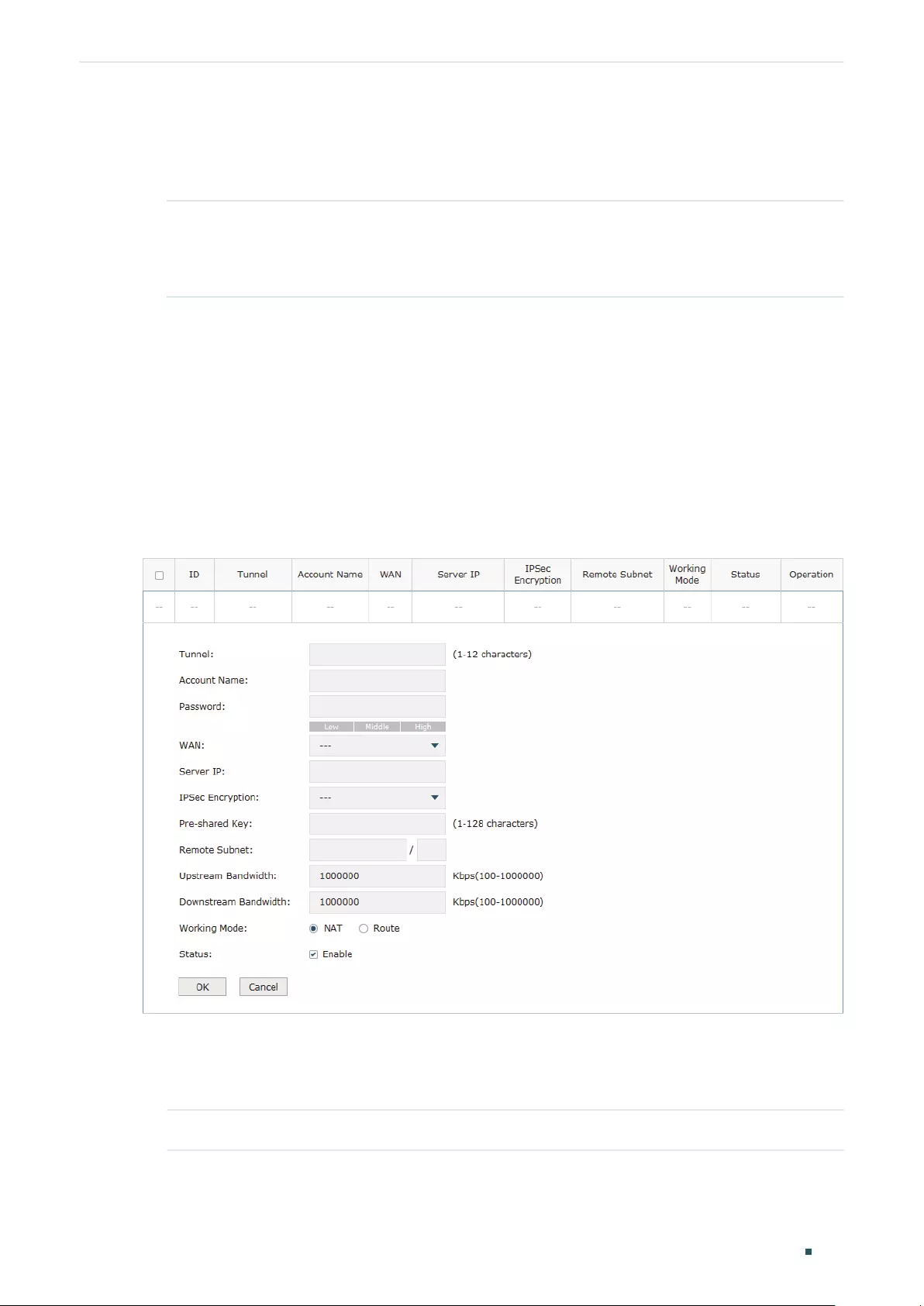
Configuring VPN L2TP Configuration
User Guide 139
Follow these steps to configure the L2TP server:
1) Specify the WAN port used for L2TP tunnel.
2) Specify whether to enable the encryption for the tunnel.
IPSec
Encryption
Specify whether to enable the encryption for the tunnel. If enabled, the L2TP
tunnel will be encrypted by IPSec (L2TP over IPSec). If you choose Auto, the L2TP
server will determine whether to encrypt the tunnel according to the client ‘s
encryption settings.
3) Specify the Pre-shared Key for IKE authentication.
4) Enable the L2TP tunnel.
5) Click OK.
3.4 Configuring the L2TP Client
Choose the menu VPN> L2TP > L2TP Client and click Add to load the following page.
Figure 3-4 Configuring the L2TP Client
Follow these steps to configure the L2TP client:
1) Specify the name of the L2TP tunnel and configure other relevant parameters of the
L2TP client according to your actual network environment.
Tunnel Specify the name of L2TP tunnel.

User Guide 140
Configuring VPN L2TP Configuration
Account Name Specify the account name of L2TP tunnel. It should be configured identically on
server and client.
Password Specify the password of L2TP tunnel. It should be configured identically on server
and client.
WAN Specify the WAN port used for L2TP tunnel.
Server IP Specify the IP address or domain name of L2TP server.
IPSec
Encryption
Specify whether to enable the encryption for the tunnel. If enabled, the L2TP tunnel
will be encrypted by IPSec (L2TP over IPSec).
Pre-shared Key Specify the Pre-shared Key for IKE authentication.
Remote Subnet Specify the remote network. (It’s always the IP address range of LAN on the remote
peer of the VPN tunnel.) It’s the combination of IP address and subnet mask.
Upstream
Bandwidth
Specify the uptream limited rate in Kbps for L2TP tunnel.
Downstream
Bandwidth
Specify the downstream limited rate in Kbps for L2TP tunnel.
Working Mode Specify the Working Mode as NAT or Routing.
NAT: NAT (Network Address Translation) mode allows the router to translate
source IP address of L2TP packets to its WAN IP when forwarding L2TP packets.
Route: Route mode allows the router to forward L2TP packets via routing protocol.
Status Check the box to enable the L2TP tunnel.
2) Click OK.
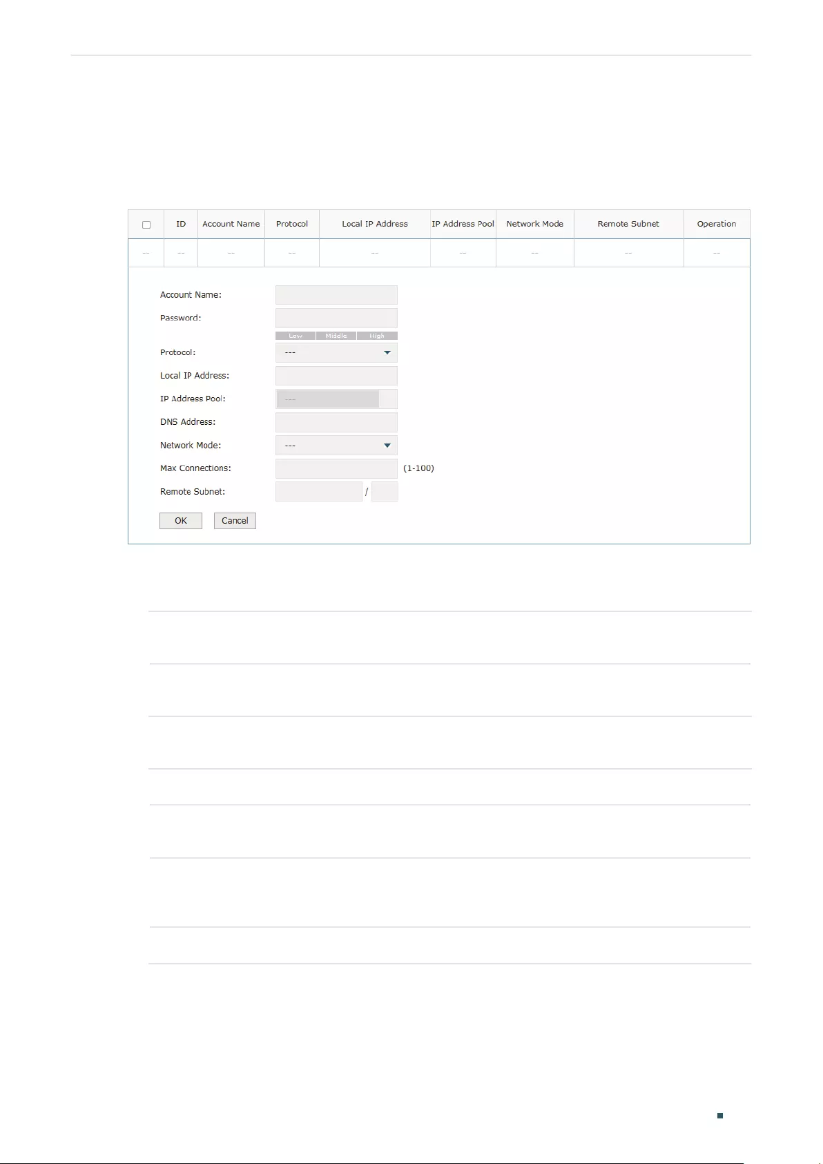
Configuring VPN L2TP Configuration
User Guide 141
3.5 (Optional) Configuring the L2TP Users
Choose the menu VPN> Users > Users and click Add to load the following page.
Figure 3-5 Configuring the L2TP User
Follow these steps to configure the L2TP User:
1) Specify the account name and password of the L2TP User.
Account Name Specify the account name used for the VPN tunnel. This parameter should be the
same with that of the L2TP client.
Password Specify the password of user. This parameter should be the same with that of the
L2TP client.
2) Specify the protocol as L2TP and configure other relevant parameters according to
your actual network environment.
Protocol Specify the protocol for the VPN tunnel. There are two types: L2TP and PPTP.
Local IP
Address
Specify the local IP address of the tunnel. You can enter the LAN IP of the local
device.
IP Address
Pool
Specify the IP address pool from which the IP address will be assigned to the VPN
client. The IP Pool referenced here can be created on the Preferences > VPN IP
Pool page.
DNS Address Specify the DNS address to be assigned to the VPN client (8.8.8.8 for example).

User Guide 142
Configuring VPN L2TP Configuration
Network Mode Specify the network mode. There are two modes:
Client-to-LAN: Select this option when the L2TP/PPTP client is a single host.
LAN-to-LAN: Select this option when the L2TP/PPTP client is a VPN gateway. The
tunneling request is always initiated by a device.
Max
Connections
Specify the maximum number of connections that the tunnel can support.
Remote Subnet Specify a remote network. (This is the IP address range of the LAN on the remote
peer of the L2TP/PPTP tunnel.) It’s the combination of IP address and subnet mask.
3) Click OK.
3.6 Verifying the Connectivity of L2TP VPN Tunnel
Choose the menu VPN> L2TP > Tunnel List to load the following page.
Figure 3-6 L2TP VPN Tunnel List
The Tunnel List shows the information of the established L2TP VPN tunnel.
Account Name Displays the account name of L2TP tunnel.
Mode Displays whether the device is server or client.
Tunnel Displays the name of the tunnel when the router is a L2TP client.
Local IP Displays the local IP address of the tunnel.
Remote IP Displays the remote real IP address of the tunnel.
Remote Local
IP
Displays the remote local IP address of the tunnel.
DNS Displays the DNS address of the tunnel.
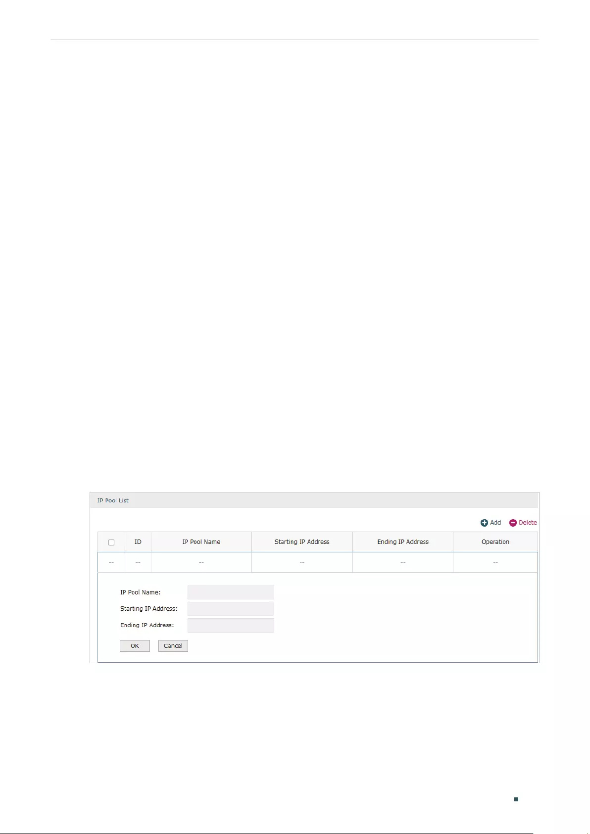
Configuring VPN PPTP Configuration
User Guide 143
4 PPTP Configuration
To complete the PPTP configuration, follow these steps:
1) Configure the VPN IP pool.
2) Configure PPTP globally.
3) Configure the PPTP server/client.
4) (Optional) Configure the PPTP users.
5) Verify the connectivity of the PPTP VPN tunnel.
Configuration Guidelines
When the network mode is configured as Client-to-LAN and the router acts as the PPTP
server, you don’t need to configure a PPTP client on the router.
When the network mode is configured as LAN-to-LAN and the router acts as the PPTP
client gateway, you don’t need to configure PPTP users on the router.
4.1 Configuring the VPN IP Pool
Choose the menu Preferences> VPN IP Pool > VPN IP Pool and click Add to load the
following page.
Figure 4-1 Configuring the VPN IP Pool
Follow these steps to configure the VPN IP Pool:
1) Specify the name of the IP Pool.
2) Specify the starting IP address and ending IP address for the IP Pool.

User Guide 144
Configuring VPN PPTP Configuration
Note:
• The starting IP address should not be greater than the ending IP address.
• The ranges of IP Pools cannot overlap.
4.2 Configuring PPTP Globally
Choose the menu VPN> PPTP > Global Config to load the following page.
Figure 4-2 Configuring PPTP Globally
In the General section, configure PPTP parameters globally and click Save.
PPTP Hello
Interval
Specify the time interval of sending PPTP peer detect packets.
PPP Hello
Interval
Specify the time interval of sending PPP peer detect packets.
NetBIOS
Passthrough
Enable NetBIOS Passthrough function to allow NetBIOS packets to be broadcasted
through VPN tunnel.
4.3 Configuring the PPTP Server
Choose the menu VPN> PPTP > PPTP Server and click Add to load the following page.
Figure 4-3 Configuring the PPTP Server
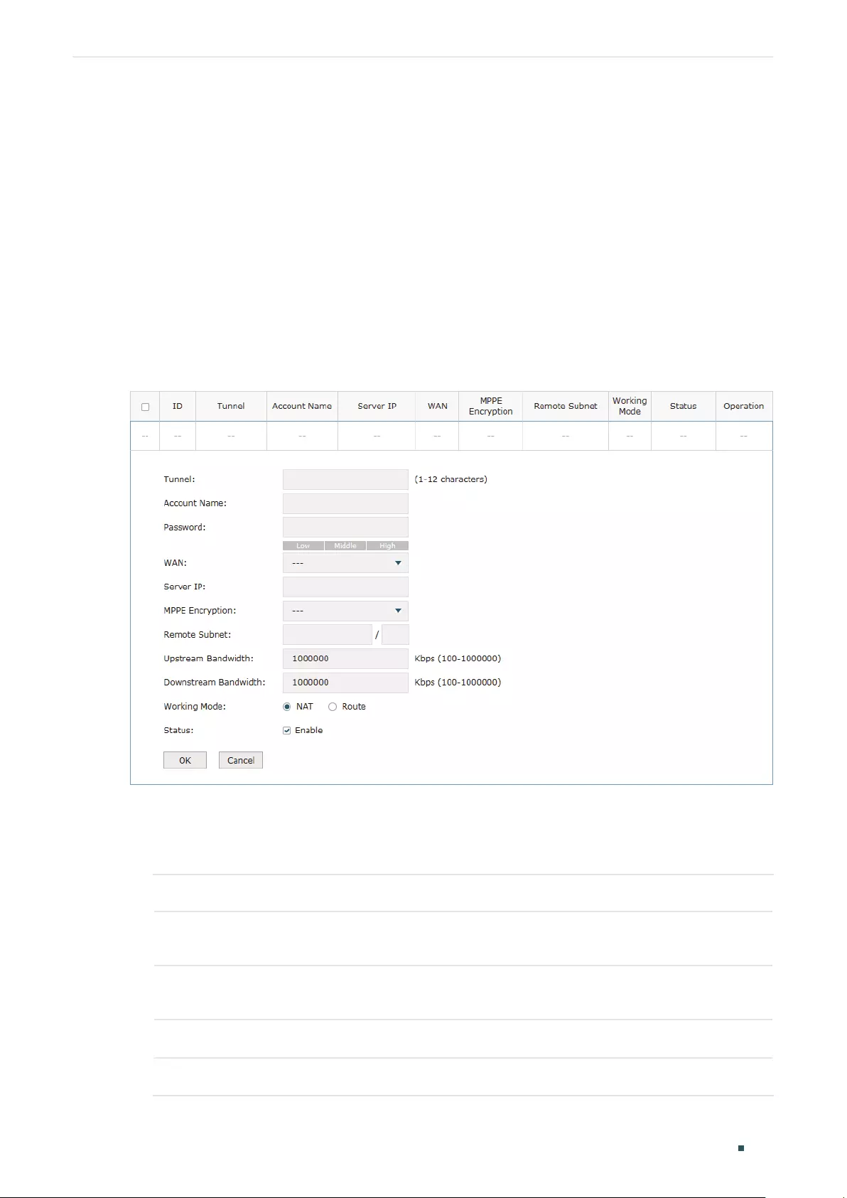
Configuring VPN PPTP Configuration
User Guide 145
Follow these steps to configure the PPTP server:
1) Specify the WAN port used for PPTP tunnel.
2) Specify whether to enable the MPPE encryption for the PPTP tunnel.
3) Enable the PPTP tunnel.
4) Click OK.
4.4 Configuring the PPTP Client
Choose the menu VPN> PPTP > PPTP Client and click Add to load the following page.
Figure 4-4 Configuring the PPTP Client
Follow these steps to configure the PPTP client:
1) Specify the name of the PPTP tunnel and configure other relevant parameters of the
PPTP client according to your actual network environment.
Tunnel Specify the name of PPTP tunnel.
Account Name Specify the account name of PPTP tunnel. It should be configured identically on
server and client.
Password Specify the password of PPTP tunnel. It should be configured identically on server
and client.
WAN Specify the WAN port used for PPTP tunnel.
Server IP Specify the IP address or domain name of PPTP server.

User Guide 146
Configuring VPN PPTP Configuration
MPPE
Encryption
Specify whether to enable the encryption for the tunnel. If enabled, the PPTP tunnel
will be encrypted by MPPE.
Remote Subnet Specify the remote network. (It’s always the IP address range of LAN on the remote
peer of the VPN tunnel.) It’s the combination of IP address and subnet mask.
Upstream
Bandwidth
Specify the uptream limited rate in Kbps for PPTP tunnel.
Downstream
Bandwidth
Specify the downstream limited rate in Kbps for PPTP tunnel.
Working Mode Specify the Working Mode as NAT or Routing.
NAT: NAT (Network Address Translation) mode allows the router to translate
source IP address of PPTP packets to its WAN IP when forwarding PPTP packets.
Route: Route mode allows the router to forward PPTP packets via routing protocol.
Status Check the box to enable the PPTP tunnel.
2) Click OK.
4.5 Configuring the PPTP Users
Choose the menu VPN> Users > Users and click Add to load the following page.
Figure 4-5 Configuring the PPTP User
Follow these steps to configure the PPTP User:
1) Specify the account name and password of the PPTP User.

Configuring VPN PPTP Configuration
User Guide 147
Account Name Specify the account name used for the VPN tunnel. This parameter should be the
same as that of the PPTP client.
Password Specify the password of users. This parameter should be the same as that of the
PPTP client.
2) Specify the protocol as PPTP and configure other relevant parameters according to
your actual network environment.
Protocol Specify the protocol for the VPN tunnel. There are two types: L2TP and PPTP.
Local IP
Address
Specify the local IP address of the tunnel. You can enter the LAN IP of the local
device.
IP Address
Pool
Specify the IP address pool from which the IP address will be assigned to the VPN
client. The IP Pool referenced here can be created on the Preferences > VPN IP
Pool page.
DNS Address Specify the DNS address to be assigned to the VPN client (8.8.8.8 for example).
Network Mode Specify the network mode. There are two modes:
Client-to-LAN: Select this option when the PPTP/PPTP client is a single host.
LAN-to-LAN: Select this option when the PPTP/PPTP client is a VPN gateway. The
tunneling request is always initiated by a device.
Max
Connections
Specify the maximum number of connections that the tunnel can support.
Remote Subnet Specify a remote network. (This is the IP address range of the LAN on the remote
peer of the PPTP/PPTP tunnel.) It’s the combination of IP address and subnet mask.
3) Click OK.
4.6 Verifying the Connectivity of PPTP VPN Tunnel
Choose the menu VPN> PPTP > Tunnel List to load the following page.
Figure 4-6 PPTP VPN Tunnel List
The Tunnel List shows the information of the established PPTP VPN tunnel.
Account Displays the account name of PPTP tunnel.
Mode Displays whether the device is server or client.

User Guide 148
Configuring VPN PPTP Configuration
Tunnel Displays the name of the tunnel when the router is a PPTP client.
Local IP Displays the local IP address of the tunnel.
Remote IP Displays the remote real IP address of the tunnel.
Remote Local
IP
Displays the remote local IP address of the tunnel.
DNS Displays the DNS address of the tunnel.

Configuring VPN Configuration Examples
User Guide 149
5 Configuration Examples
5.1 Example for Configuring IPSec VPN
5.1.1 Network Requirements
A business requires a highly secure connection between one of the branch offices and the
head office. Thus we can build the site-to-site IPSec VPN tunnel between the branch office
and the head office to establish the virtual private connection.
5.1.2 Network Topology
As is shown below, computers in the branch office are connected to the banch office VPN
gateway router B via the LAN port, and the internal server group is connected to the head
office VPN gateway router A via the LAN port.
Figure 5-1 Site-to-Site IPSec VPN Topology
Router B
WAN IP: 20.20.20.1
LAN IP: 192.168.1.1
Router A
WAN IP: 30.30.30.1
LAN IP: 192.168.2.1
Branch Oce
LAN: 192.168.1.0/24
Branch Oce Gateway
Server Group
LAN: 192.168.2.0/24
Head Oce Gateway
Internet
VPN Tunnel
5.1.3 Configuration Scheme
To meet the requirements, configure IPSec policy on Router A and Router B. (As the
network topology above shows, two VPN gateways are connected via the internet, so the
network mode should be configured as LAN-to-LAN.) Then verify whether the IPSec VPN
tunnel is established successfully.
The following section provides the configuration procedure.
5.1.4 Configuration Procedure
Follow the steps below to configure IPSec policy on Router A and Router B:

User Guide 150
Configuring VPN Configuration Examples
Configuring the Router A
1) Choose the menu VPN > IPSec > IPSec Policy to load the following page. Click Add.
Figure 5-2 IPSec Policy List
2) The following page will appear. Specify the IPSec Policy Name as tplink and configure
the Mode as LAN-to-LAN as the network is connected to the other network, then
configure other relevant parameters. Keep Enable selected as the Status of this entry.
Click OK.
Figure 5-3 Configuring the IPSec Policy
3) Choose the menu VPN > IPSec > IPSec Policy and click Advanced Settings to load the
following page. Advanced settings include IKEv1 phase-1 settings and IKEv1 phase-2
settings. You can keep the default advanced settings.
In the Phase-1 Settings section, configure the IKE phase-1 parameters and click OK.
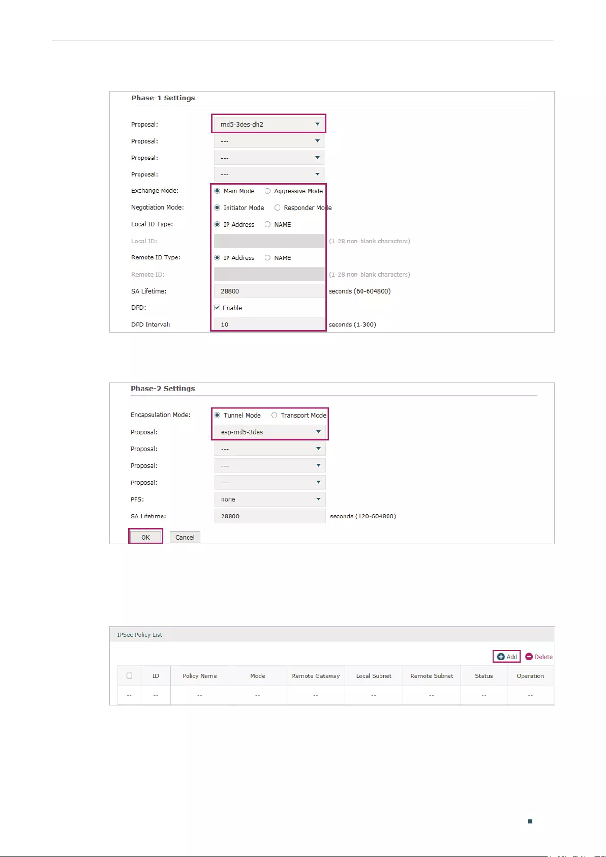
Configuring VPN Configuration Examples
User Guide 151
Figure 5-4 Configuring the IKE Phase-1 Parameters
In the Phase-2 Settings section, configure the IKE phase-2 parameters and click OK.
Figure 5-5 Configuring the IKE Phase-2 Parameters
Configuring the Router B
1) Choose the menu VPN > IPSec > IPSec Policy to load the following page. Click Add.
Figure 5-6 IPSec Policy List
2) The following page will appear. Specify the IPSec Policy Name as tplink and configure
the Mode as LAN-to-LAN as the network is connected to the other network, then
configure other relevant parameters. Keep Enable selected as the Status of this entry.
Click OK.

User Guide 152
Configuring VPN Configuration Examples
Figure 5-7 Configuring the IPSec Policy
3) Choose the menu VPN > IPSec > IPSec Policy and click Advanced Settings to load the
following page. Advanced settings include IKEv1 phase-1 settings and IKEv1 phase-2
settings. You can keep the default advanced settings.
In the Phase-1 Settings section, configure the IKE phase-1 parameters and click OK.
Figure 5-8 Configuring the IKE Phase-1 Parameters
In the Phase-2 Settings section, configure the IKE phase-2 parameters and click OK.
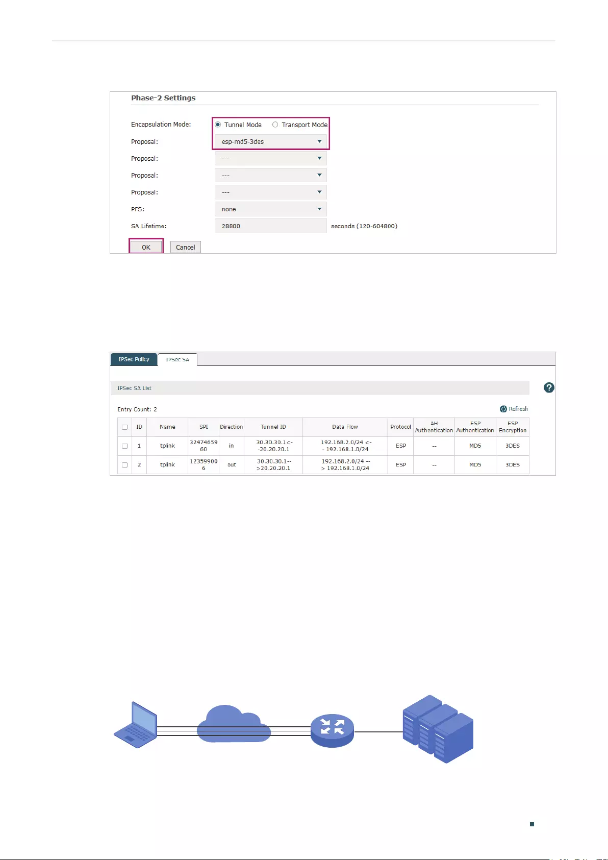
Configuring VPN Configuration Examples
User Guide 153
Figure 5-9 Configuring the IKE Phase-2 Parameters
Verifying the connectivity of the IPSec VPN tunnel
On Router A or Router B, choose the menu VPN > IPSec > IPSec SA to view the
information of the established IPSec VPN tunnel. Here we take router A for example.
Figure 5-10 Viewing the IPSec SA
5.2 Example for Configuring L2TP VPN
5.2.1 Network Requirements
Employees out of the office need to communicate with the head office and access the
internal resources at any time. And the communication data needs to be well protected.
Thus we can build the remote access VPN tunnel between the employees on official
business and the gateway device of the head office.
In this scenario, both PPTP and L2TP can be used. Here we take L2TP VPN as an example.
Figure 5-11 Remote Access L2TP VPN Topology
Remote PC
Server Group
LAN: 192.168.2.0/24
Head Oce Gateway
Router
Internet
L2TP VPN Tunnel
WAN1 LAN
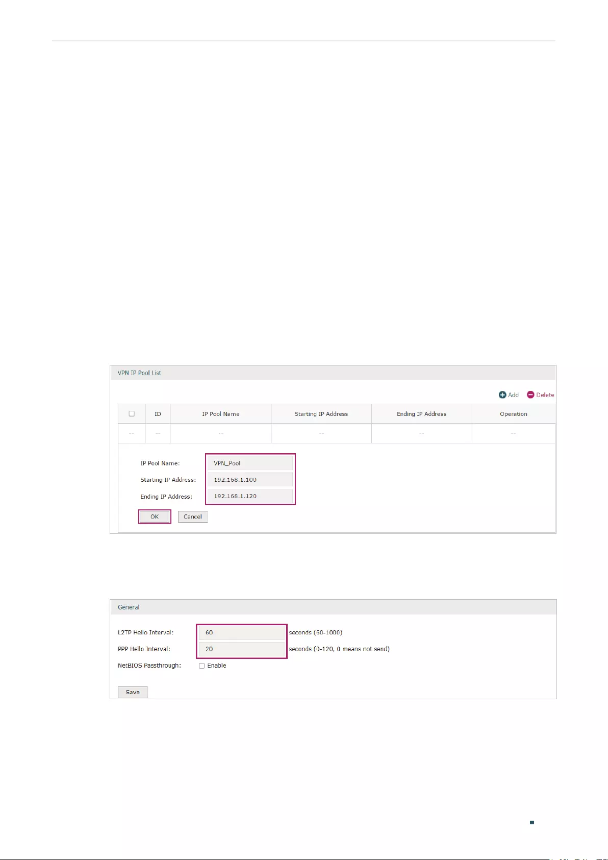
User Guide 154
Configuring VPN Configuration Examples
5.2.2 Configuration Scheme
To meet the requirements, configure L2TP server on the router, and configure L2TP client
on the remote PC. For the remote PC, use Windows built-in L2TP software or third-party
L2TP software to connect to L2TP server. Then verify whether the L2TP VPN tunnel is
established successfully.
The following section provides the configuration procedure.
5.2.3 Configuration Procedure
Follow the steps below to configure L2TP VPN on the router and PC:
Configuring the router
1) Choose the menu Preferences > VPN IP Pool > VPN IP Pool to load the configuration
page, and click Add. Specify the pool name as VPN_Pool, and enter the starting/ending
IP address.
Figure 5-12 Configuring the VPN IP Pool
2) Choose the menu VPN> L2TP > Global Config to load the following page. You can keep
the L2TP/PPP hello interval as the default value.
Figure 5-13 Configuring L2TP Globally
3) Choose the menu VPN> L2TP > L2TP Server to load the configuration page, and
click Add. Specify WAN1 as the outgoing interface of L2TP VPN tunnel, enable IPSec
encryption and specify the pre-shared key as 123456.

Configuring VPN Configuration Examples
User Guide 155
Figure 5-14 Configuring the L2TP Server
4) Choose the menu VPN> Users > Users to load the configuration page, and click
Add. Specify the account name as tplink, and enter the password 123456. Select
the protocol as L2TP, specify the LAN IP (192.168.0.1) as the local IP address of the
gateway router, select VPN_Pool as the IP address pool to assign an IP address for the
L2TP client, enter the DNS address (for example, 8.8.8.8), select the network mode as
Client-to-LAN as the VPN gateway is connected to a host, specify the max connections
as 3, then click OK.
Figure 5-15 Configuring the VPN User
Configuring the Remote PC
For remote PC, use Windows built-in L2TP software or third-party L2TP software to
connect to L2TP server. For more information, you can refer to our official website:
http://www.tp-link.com/us/faq-1629.html

User Guide 156
Configuring VPN Configuration Examples
Verifying the connectivity of the L2TP VPN tunnel
On the router, choose the menu VPN> L2TP > Tunnel List to verify the connectivity of
the L2TP VPN tunnel.
Figure 5-16 Viewing the L2TP VPN Tunnel
5.3 Example for Configuring PPTP VPN
5.3.1 Network Requirements
The employees at headquarters need to access the network resources through the
server at the US subsidiary via a secure connection. Thus we can build the remote access
VPN tunnel between the employees at headquarter and the gateway device of the US
subsidiary.
In this scenario, both PPTP and L2TP can be used. Here we take PPTP VPN as an example.
Figure 5-17 Remote Access PPTP VPN Topology
Remote PC
IP: 192.168.0.1
US subsidiary Gateway
Router A
Internet
PPTP VPN Tunnel
WAN1 LAN
Head Oce Gateway
Router
5.3.2 Configuration Scheme
To meet the requirements, configure PPTP server on Router A, and configure PPTP
client on the remote PC. For Router A, make sure to add a Multi-Nets NAT entry. This will
ensure Router A will not drop the packets sent from the remote PC. For the remote PC,
use Windows built-in PPTP software or third-party PPTP software to connect to the PPTP
server. Then verify whether the PPTP VPN tunnel is established successfully.
The following section provides the configuration procedure.
5.3.3 Configuration Procedure
Follow the steps below to configure PPTP VPN on Router A and PC:
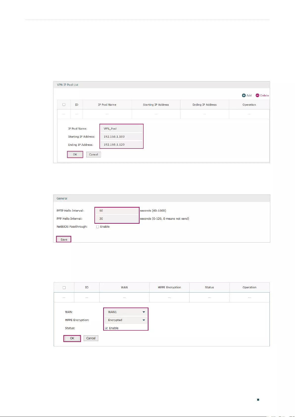
Configuring VPN Configuration Examples
User Guide 157
Configuring Router A
1) Choose the menu Preferences > VPN IP Pool > VPN IP Pool to load the configuration
page, and click Add. Specify the pool name as VPN_Pool, and enter the starting/ending
IP address.
Figure 5-18 Configuring the VPN IP Pool
2) Choose the menu VPN> PPTP > Global Config to load the following page. You can keep
the PPTP/PPP hello interval as the default value.
Figure 5-19 Configuring PPTP Globally
3) Choose the menu VPN> PPTP > PPTP Server to load the configuration page, and
click Add. Specify WAN1 as the outgoing interface of PPTP VPN tunnel, enable MPPE
encryption.
Figure 5-20 Configuring the PPTP Server
4) Choose the menu VPN> Users > Users to load the configuration page, and click
Add. Specify the account name as tplink, and enter the password 123456. Select
the protocol as PPTP, specify the LAN IP (192.168.0.1) as the local IP address of the
gateway router, select VPN_Pool as the IP address pool to assign an IP address for
the PPTP client, enter the DNS address (for example, 8.8.8.8), select the network
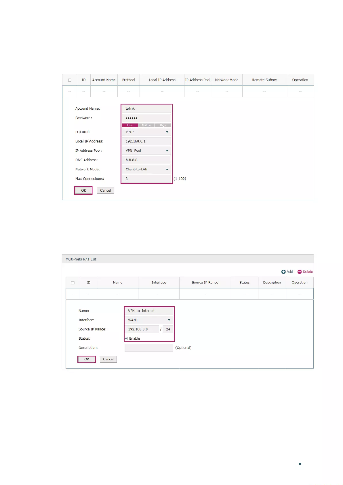
User Guide 158
Configuring VPN Configuration Examples
mode LAN-to-LAN as the network is connected to the other network, specify the max
connections as 3, then click OK.
Figure 5-21 Configuring the VPN User
5) Choose the menu Tramsmission > NAT > Multi-Nets NAT to load the configuration
page, and click Add. Specify the entry name as VPN_to_Internet, and choose WAN1 as
the outgoing interface. Specify the LAN subnet (192.168.0.0) on which the employees
are as the Source IP Range, Keep Enable selected as the Status of this entry. Click OK.
Figure 5-22 Adding the Multi-Nets NAT Entry
Configuring the Remote PC
For remote PC, use Windows built-in PPTP software or third-party PPTP software to
connect to PPTP server. For more information, you can refer to our official website:
http://www.tp-link.com/us/faq-1629.html

Configuring VPN Configuration Examples
User Guide 159
Verifying the connectivity of the PPTP VPN tunnel
On the router, choose the menu VPN> PPTP > Tunnel List to verify the connectivity of
the PPTP VPN tunnel.
Figure 5-23 Viewing the PPTP VPN Tunnel

Part 9
Configuring Authentication
CHAPTERS
1. Overview
2. Local Authentication Configuration
3. RADIUS Authentication Configuration
4. Onekey Online Configuration
5. Guest Resources Configuration
6. Viewing the Authentication Status
7. Configuration Example

Configuring Authentication Overview
User Guide 161
1 Overview
Portal authentication, also known as Web authentication, is usually deployed in a guest-
access network (like a hotel or a coffee shop) to control the client’s internet access. In
portal authentication, all the client’s HTTP requests will be redirected to an authentication
page first. The client needs to enter the account information on the page to authenticate,
then can visit the internet after the authentication succeeded.
1.1 Typical Topology
The typical topology of portal authentication is shown as below:
Figure 1-1 Topology of Portal Authentication
Client
Access Device
Web Server
Authentication Server
Client
The end device that needs to be authenticated before permitted to access the internet.
Access Device
The device that supports portal authentication. In this configuration guide, it means the
router. The Access Device helps to: redirect all HTTP requests to the Web Server before
authenticated; interact with the Authentication Server to authenticate the client during
the authentication process; permit users to access the internet after the authentication
succeeded.
Web Server
The web server responds to client’s HTTP requests, and returns an authentication login
page.
Authentication Server
The authentication server records the information of the user’s account, and interacts with
the access device to authenticate clients.

User Guide 162
Configuring Authentication Overview
1.2 Portal Authentication Process
The portal authentication process is shown as below:
Figure 1-2 Portal Authentication Process
Client
http://
Visit the Internet
Enter the Username and Password in the login page
Forwards the username and password to the Authentication Server
Returns the authentication result
Returns the authentication result
Visit the Web Server
Returns the authentication login page
Redirect the client to Web Server
Router Web Server Authentication Server
1) The client is connected to the router but not authenticated, and starts to visit the
internet through HTTP;
2) The router redirects the client’s HTTP request to the web server;
3) The client visits the web server;
4) The Web server returns the authentication login page to the client;
5) The client enters the username and password on the authentication login page;
6) The router forwards the username and password to the authentication server;
7) The authentication server returns the authentication result to the router;
The router replies to the client with the authentication result;
9) The client visits the internet after the authentication succeeded.
1.3 Supported Features
To configure portal authentication, you need to configure both the web server and the
authentication server. The web server provides the authentication page for login; the
authentication server records the account information and authenticates the clients.

Configuring Authentication Overview
User Guide 163
1.3.1 Supported Web Server
The router has a built-in web server and also supports external web server. You can
configure the authentication page either using the built-in server or the external server.
Custom Page
You can use the built-in web server and customize the authentication page on your router.
External Links
You can specify the external web server and configure the authentication page on the
external web server.
1.3.2 Supported Authentication Server
The router provides three types of portal authentication:
RADIUS Authentication
In RADIUS authentication, you can specify an external RADIUS server as the authentication
server. The user’s account information are recorded in the RADIUS server.
Local Authentication
If you don’t have an additional RADIUS server, you can choose local authentication. In local
authentication, the router uses the built-in authentication server to authenticate. The built-
in authentication server can record at most 500 local user accounts, and each account is
can be used for at most 1024 clients to authenticate.
Onekey Online
In Onekey Online Authentication, users can access the network without entering any
account information.
1.3.3 Guest Resources
Guest Resources is used to provide free resources for users before they pass the portal
authentication.

User Guide 164
Configuring Authentication Local Authentication Configuration
2 Local Authentication Configuration
To configure local authentication, follow the steps:
1) Configure the authentication page.
2) Configure the local user account.
2.1 Configuring the Authentication Page
The browser will redirect to the authentication page when the client try to access the
internet. On the authentication page, the user need to enter the username and password to
log in. After the authentication succeeded, the user can access the internet.
Choose the menu Authentication > Authentication Settings > Web Authentication to
load the following page.
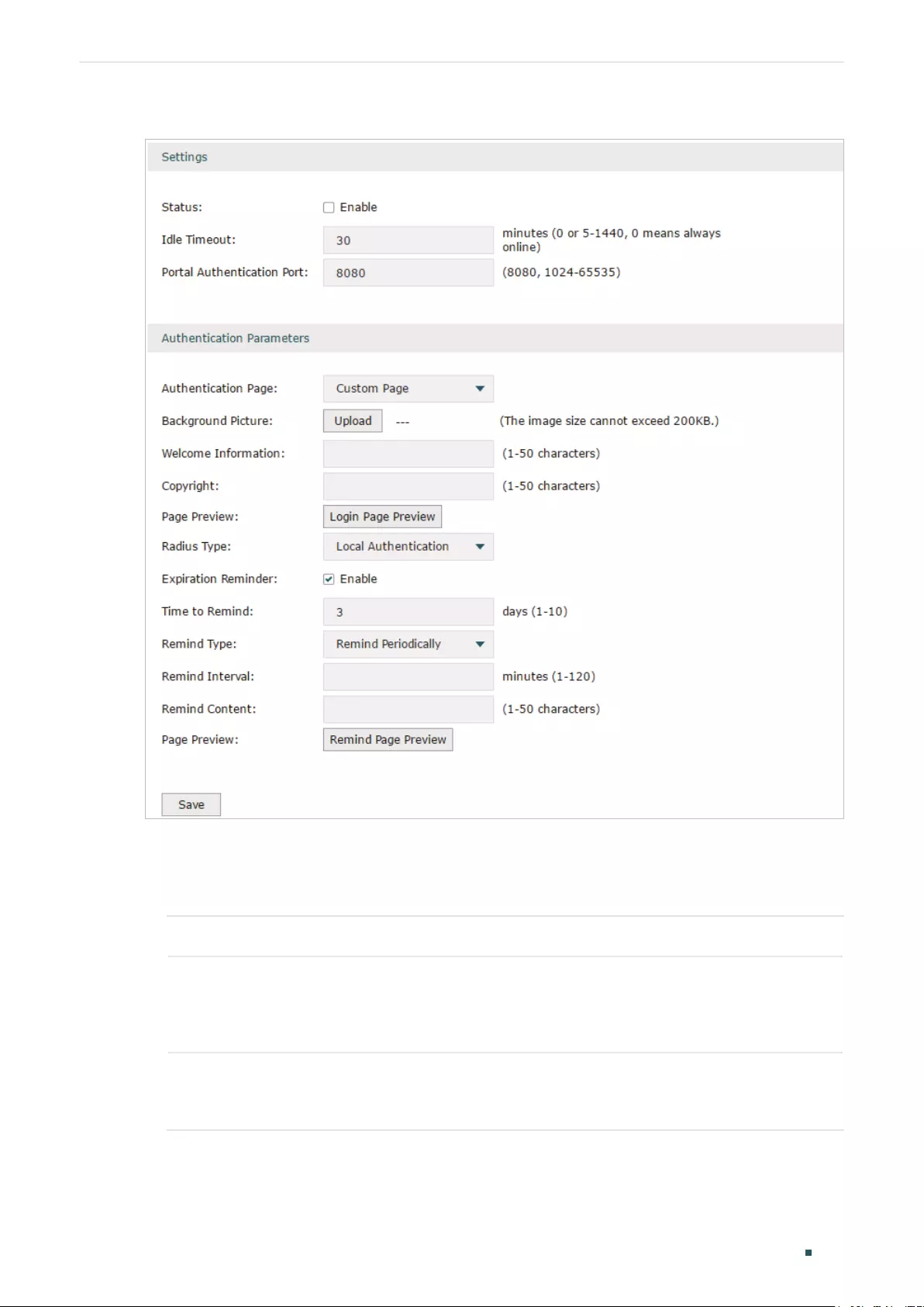
Configuring Authentication Local Authentication Configuration
User Guide 165
Figure 2-1 Configuring the Authentication Page
Follow these steps to configure authentication page:
1) In the Settings section, enable authentication status, configure the idle timeout and
portal authentication port.
Status Check the box to enable portal authentication.
Idle Timeout Specify the idle timeout. The client will be disconnected after the specified
period (Idle Timeout) of inactivity, and is required to be authenticated again.
Value 0 means the client will always keep online until the authentication timeout
leased, even if the client remains inactive.
Portal
Authentication
Port
Enter the service port for portal authentication. The default setting is 8080.
2) In the Authentication Parameters section, configure the parameters of the
authentication page.

User Guide 166
Configuring Authentication Local Authentication Configuration
Authentication
Page
Choose the authentication page type.
Custom: You can use the built-in web server to customize the authentication
page by specifying the background picture, welcome information and copyright
information.
External Links: You can specify a external web server to provide the
authentication page by entering the URL of the external web server.
Background
Picture
Click the Upload button to choose a local image as the background picture of
the custom authentication page.
Welcome
Information
Specify the welcome information to be displayed on the custom authentication
page.
Copyright Specify the copyright information to be displayed on the custom authentication
page.
Page Preview Click the Login Page Preview button, and you can preview the customized
authentication page
Authentication
URL
Specify the URL for authentication page if you choose the Authentication Page
as “External Links“. The browser will redirect to this URL when the client starts
the authentication.
Success Redirect
URL
Specify the Success Redirect URL if you choose the Authentication Page as
“External Links“. The browser will redirect to this URL after the authentication
succeeded.
Fail redirect URL Specify the Fail Redirect URL if you choose the Authentication Page as “External
Links“. The browser will redirect to this URL if the authentication failed.
Note:
If the web server is not deployed in the LAN, you need to create a Guest Resource entry to ensure the
client can access the external web server before the authentication succeeded. For the configuration
of Guest Resource, go to Guest Resources Configuration.
3) Choose the authentication type, and configure the expiration reminder, then click Save.
Authentication
Type
Choose the authentication type as Local Authentication.
Expiration
Reminder
Check the box to enable expiration reminder. A remind page will appear to
remind users when the online time is about to expire.
Time to Remind Specify the number of days before the expiration date to remind users.
Remind Type Specify the remind type.
Remind Once: Remind the user only once after the authentication succeeded.
Remind Periodically: Remind users at specified intervals during the remind
period.

Configuring Authentication Local Authentication Configuration
User Guide 167
Remind Interval Specify the interval at which the router reminds users if the remind type is
specified as “Remind Periodically“.
Remind Content Specify the remind content. The content will be displayed on the Remind page.
Page Preview Click the button to view the remind page.
2.2 Configuring the Local User Account
In Local authentication, the router uses the built-in authentication server to authenticate
users. You need to configure the authentication accounts for the local users.
The router supports two types of local users:
Formal User: If you want to provide the user with network service for a long period of time (in
days), you can create Formal User accounts for them.
Free User: If you want to provide the user with network service for a short period of time (in
minutes), you can create Free User accounts for them.
2.2.1 Configuring the Local User Account
Configuring the Formal User Account
Choose the menu Authentication > User Management > User Management and click Add
to load the following page.

User Guide 168
Configuring Authentication Local Authentication Configuration
Figure 2-2 Configuring the Formal User Account
Specify the user type, configure the username and password for the formal user account,
and configure the other corresponding parameters. Then click OK.
User Type Specify the user type as Formal User.
Username /
Password
Specify the username and password of the account. The username cannot be the
same as any existing one.
Expiration Date Specify the expiration date of the account. The formal user can use this account to
authenticate before this date.
Authentication
Peroid
Specify the period during which the client is allowed to be authenticated.
MAC Binding
Type
Specify the MAC Binding type. There are three types of MAC Binding: No binding,
Static Binding and Dynamic Binding.
No Binding: The client’s MAC address will not be bound.
Static Binding: Manually enter the MAC address of the client to be bound. Only the
bound client is able to use the username and password to authenticate.
Dynamic Binding: The MAC address of the first client that passes the authentication
will be bound. Afterwards only the bound client is able to use the username and
password to authenticate.
MAC Address Enter the MAC address of the client to be bound if you choos the MAC Binding type
as «Static Binding».
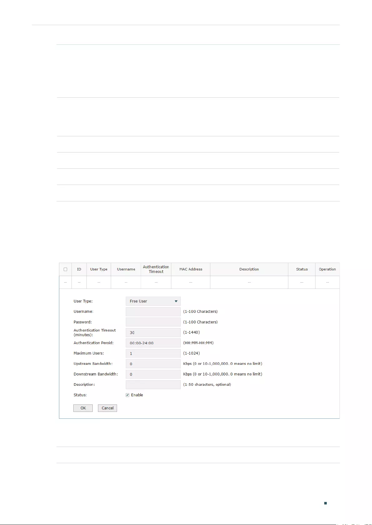
Configuring Authentication Local Authentication Configuration
User Guide 169
Maximum Users Specify the maximum number of users that are allowed use this account to
authenticate.
Note: If the MAC Binding Type is either Static Binding or Dynamic Binding, only one
client can use this username and password to authenticate, i.e., the bound client,
even if the value of Maximum Users is configured to be greater than one.
Upstream
Bandwidth /
Downstream
Bandwidth
Optional. Specify the upstream / downstream bandwidth for the user. 0 means no
limit.
Name Optional. Record the user’s name.
Telephone Optional. Record the user’s telephone number.
Description Optional. Enter a brief description for the user.
Status Check the box to enable this account.
Configuring the Free User Account
Choose the menu Authentication > User Management > User Management and click Add
to load the following page.
Figure 2-3 Configuring the Free User Account
Specify the user type, configure the username and password for the free user account, and
configure the other corresponding parameters. Then click OK.
User Type Specify the user type as Free User.

User Guide 170
Configuring Authentication Local Authentication Configuration
Username /
Password
Specify the username and password of the user account. The username cannot be
the same as any existing one.
Authentication
Timeout
Specify the free duration of the account. The default value is 30 minutes.
Maximum Users Specify the maximum number of users that are allowed to use this username and
password to authenticate.
Upstream
Bandwidth /
Downstream
Bandwidth
Optional. Specify the upstream/downstream bandwidth for the user. 0 means no
limit.
Status Check the box to enable this account.
2.2.2 (Optional) Configuring the Backup of Local Users
Choose the menu Authentication > User Management > Configuration Backup to load
the following page.
Figure 2-4 Configuring the Formal User
To backup local users’ accounts
Click Backup button to backup all the local users accounts as a CSV file in ANSI coding
format.
To restore local users’ accounts
You can import the accounts to the router if you have backups. Click Browse to select the
file path (the backup must be a CSV file), then click Restore to restore the accounts.
You can also manually add multiple local user accounts at a time:
1) Create an Excel file and add the local user accounts to it, then save the Excel file as a
CSV file with ANSI coding format. You can click Backup to obtain a CSV file to view the
correct format.
2) Click Browse to select the file path, then click Restore to restore the file.
Note:
Using Excel to open the CSV file may cause some numerical format changes, and the number may be
displayed incorrectly. If you use Excel to edit the CSV file, please set the cell format as text.
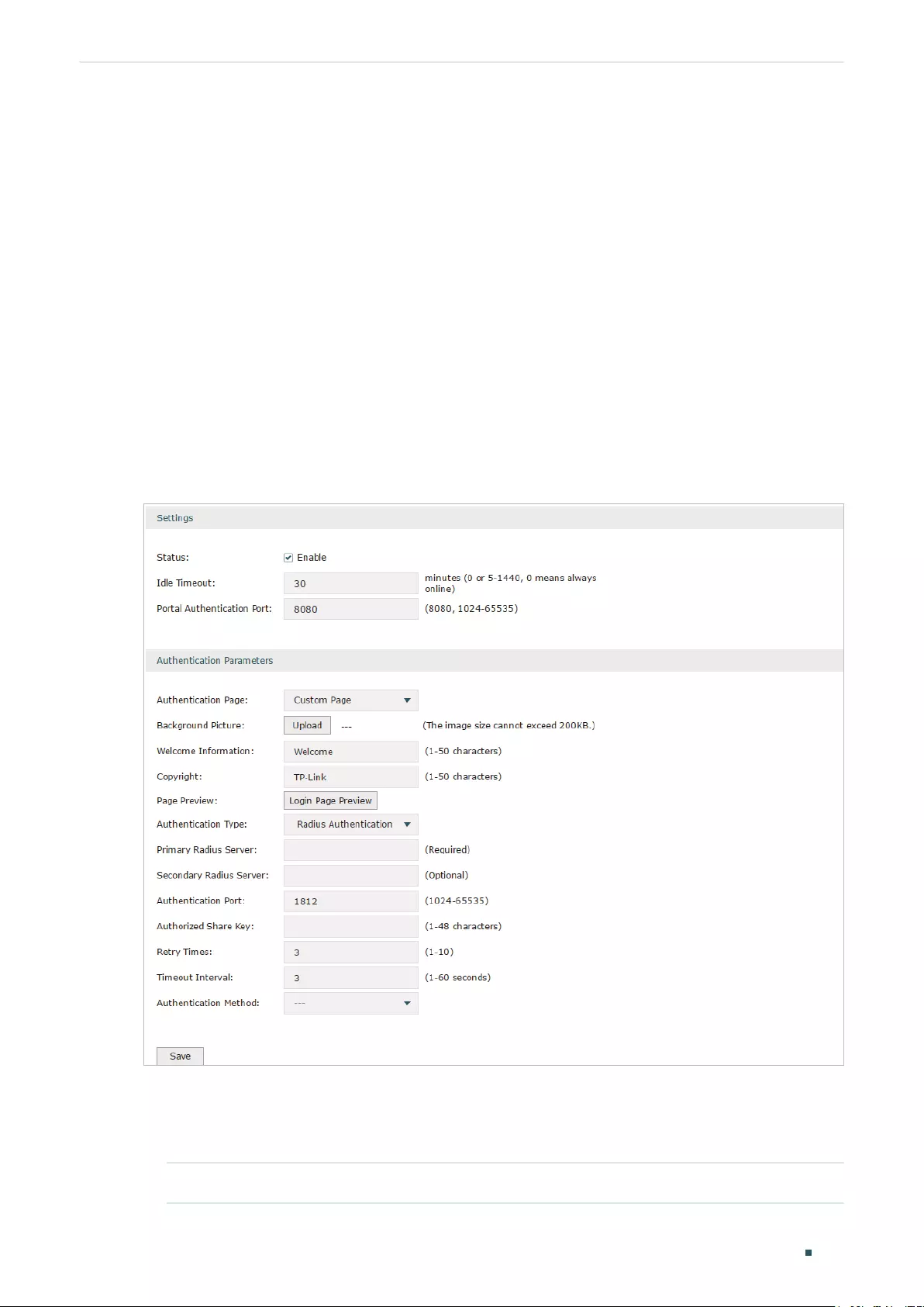
Configuring Authentication RADIUS Authentication Configuration
User Guide 171
3 RADIUS Authentication Configuration
To configure RADIUS Authentication, follow the steps:
1) Configure the authentication page.
2) Specify the external RADIUS server and configure the corresponding parameters.
3.1 Configuring RADIUS Authentication
Choose the menu Authentication > Authentication Settings > Web Authentication to
load the following page. Please make sure that the Authentication Type is configured as
Radius Authentication.
Figure 3-1 Configuring RADIUS Authentication
Follow these steps to configure RADIUS Authentication:
1) In the Settings section, enable the authentication status, configure the idle timeout and
portal authentication port.
Status Check the box to enable portal authentication.

User Guide 172
Configuring Authentication RADIUS Authentication Configuration
Idle Timeout Specify the idle timeout. The client will be disconnected after the specified
period (Idle Timeout) of inactivity, and is required to be authenticated again.
Value 0 means the client will always keep online until the authentication timeout
leased, even if the client remains inactive.
Portal
Authentication
Port
Enter the service port for portal authentication. The default setting is 8080.
2) In the Authentication Parameters section, configure the parameters of the
authentication page.
Authentication
Page
Choose the authentication page type.
Custom: You can use the built-in web server to customize the authentication
page by specifying the background picture, welcome information and copyright
information.
External Links: You can use external pages by specifying the external links as
the authentication page.
Background
Picture
Click the Upload button to choose a local image as the background picture of
the custom authentication page.
Welcome
Information
Specify the welcome information to be displayed on the custom authentication
page.
Copyright Specify the copyright information to be displayed on the custom authentication
page.
Page Preview Click the Login Page Preview button, and you can preview the customized
authentication page
Authentication
URL
Specify the URL for authentication page if you choose the Authentication Page
as “External Links“. The browser will redirect to this URL when the client starts
the authentication.
Success Redirect
URL
Specify the Success Redirect URL if you choose the Authentication Page as
“External Links“. The browser will redirect to this URL after the authentication
succeeded.
Fail Redirect URL Specify the Fail Redirect URL if you choose the Authentication Page as “External
Links“. The browser will redirect to this URL if the authentication failed.
Note:
If the web server is not deployed in the LAN, you need to create a Guest Resource entry to ensure the
client can access the external web server before the authentication succeeded. For the configuration
of Guest Resource, go to Guest Resources Configuration.
3) Specify the external RADIUS server and configure the corresponding parameters, then
click Save.
Authentication
Type
Choose the authentication type as RADIUS Authentication.

Configuring Authentication RADIUS Authentication Configuration
User Guide 173
Primary RADIUS
Server
Enter the IP address of the primary RADIUS server.
Secondary
RADIUS Server
Optional. Enter the IP address of the secondary RADIUS server. If the primary
server is down, the secondary server will be effective.
Authentication
Port
Enter the service port for RADIUS authentication. By default, it is 1812.
Authorized Share
Key
Specify the authorized share key. This key should be the same configured in the
RADIUS server.
Retry Times Specify the number of times the router will retry sending authentication requests
after the authentication failed.
Timeout Interval Specify the timeout interval that the client can wait before the RADIUS server
replies.
Authentication
Method
Specify the authentication protocol as PAP or CHAP.
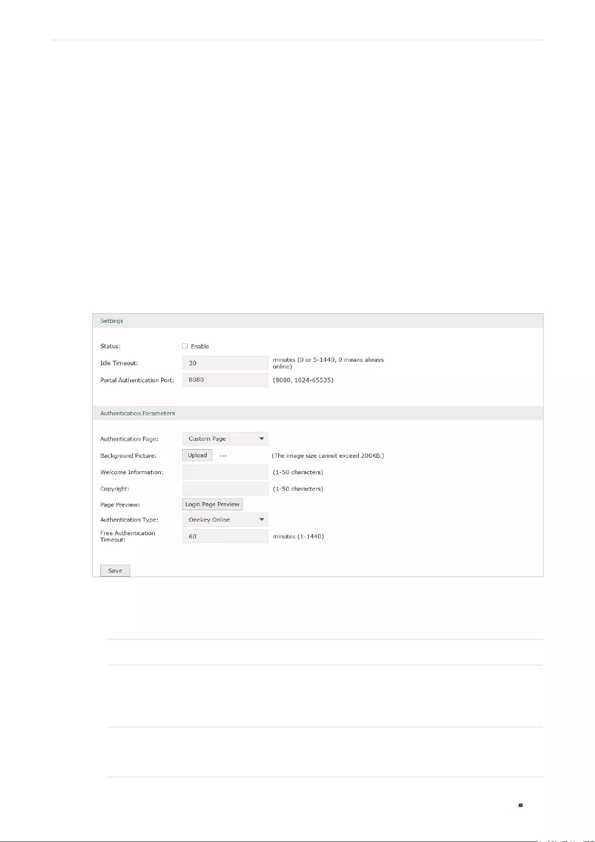
User Guide 174
Configuring Authentication Onekey Online Configuration
4 Onekey Online Configuration
In Onekey Online authentication, users only need to click the “Onekey online” button on the
authentication page, then can access the internet. The username and password are not
required.
4.1 Configuring the Authentication Page
Choose the menu Authentication > Authentication Settings > Web Authentication to
load the following page. Please make sure that the Authentication Type is configured as
Onekey Online.
Figure 4-1 Configuring the Web Authentication
Follow these steps to configure Onekey Online Authentication:
1) In the Settings section, enable the authentication status, configure the idle timeout and
portal authentication port.
Status Check the box to enable portal authentication.
Idle Timeout Specify the idle timeout. The client will be disconnected after the specified
period (Idle Timeout) of inactivity, and is required to be authenticated again.
Value 0 means the client will always keep online until the authentication timeout
leased, even if the client remains inactive.
Portal
Authentication
Port
Enter the service port for portal authentication. The default setting is 8080.

Configuring Authentication Onekey Online Configuration
User Guide 175
2) In the Authentication Parameters section, configure the parameters of the
authentication page and choose the authentication type, then click Save.
Authentication
Page
Choose the type of authentication page as Custom Page.
Note: External Links is not available for Onekey Online.
Background
Picture
Click the Upload button to choose a local image as the background picture of
the custom authentication page.
Welcome
Information
Specify the welcome information to be displayed on the custom authentication
page.
Copyright Specify the copyright information to be displayed on the custom authentication
page.
Page Preview Click the Login Page Preview button, and you can preview the customized
authentication page
Authentication
Type
Choose the authentication type as Onekey Online.
Free
Authentication
Timeout
Specify the free duration for Onekey Online. When the free duration expired,
users can click “Onekey Online“ button on the authentication page to continue
to visit the internet.

User Guide 176
Configuring Authentication Guest Resources Configuration
5 Guest Resources Configuration
Guest resources are limited network resources provided for users before they pass the
portal authentication.
You can configure the guest resources in two ways:
Five Tuple Type
Specify the client and the network resources the client can visit based on the settings of
IP address, MAC address, VLAN ID, service port and protocol. It is recommended to select
Five Tuple Type when the IP address and service port of the free network resource are
already known.
URL Type
Specify the client and the network resources the client can visit based on the settings of
the URL, IP address, MAC address and service port. It is recommended to select URL Type
when the URL of the free network resource is already known.
Note:
By default, the Guest Resource table is empty, which means all the clients cannot visit any network
resource before they pass the portal authentication.
5.1 Configuring the Five Tuple Type
Choose the menu Authentication > Authentication Settings > Guest Resources and click
Add to load the following page.

Configuring Authentication Guest Resources Configuration
User Guide 177
Figure 5-1 Configuring the Five Tuple Type
Specify the client and the network resources the client can visit by configuring the IP
address, MAC address and service port, then click OK.
Name Enter the name of the guest resource entry.
Type Choose the guest resource type as Five Tuple Type.
Source IP Range Specify the IP range of the client(s) by entering the network address and subnet
mask bits. Only the specified clients can visit the guest resources.
Destination IP
Range
Specify the IP range of the server(s) that provides the guest resources by entering
the network address and subnet mask bits.
Source MAC
Address
Enter the MAC address of the client.
Source Port
Range
Enter the source service port range.
Destination Port
Range
Enter the destination service port range.
Description Enter a brief description for the Guest Resources entry to make it easier to search
and manage.
Protocol Specify the protocol as TCP or UDP for the Guest Resources.
Status Check the box to enable the guest resource entry.

User Guide 178
Configuring Authentication Guest Resources Configuration
Note:
In a Guest Resource entry, if some parameter is left empty, it means the router will not restrict that
parameter. For example, if the source IP range is left empty, it means all the clients can visit the
specified guest resources.
5.2 Configuring the URL Type
Choose the menu Authentication > Authentication Settings > Guest Resources and click
Add to load the following page.
Figure 5-2 Configuring the URL
Specify the client and the network resources the client can visit by configuring the URL of
the network resource and the parameters of the clients, then click OK.
Name Enter the name of the guest resource entry.
Type Choose the guest resource type as URL Type.
URL Address Enter the URL address or IP address of the network resource that can be visited for
free.
Source IP Range Configure the IP range of the client(s) by entering the network address and subnet
mask bits.
Source MAC
Address
Enter the MAC address of the client.
Source Port
Range
Enter the source service port range.

Configuring Authentication Guest Resources Configuration
User Guide 179
Description Enter a brief description for the Guest Resources entry to make it easier to search
and manage.
Status Check the box to enable the guest resource entry.
Note:
In a Guest Resource entry, if some parameter is left empty, it means the router will not restrict that
parameter. For example, if the source IP range is left empty, it means all the clients can visit the
specified guest resources.
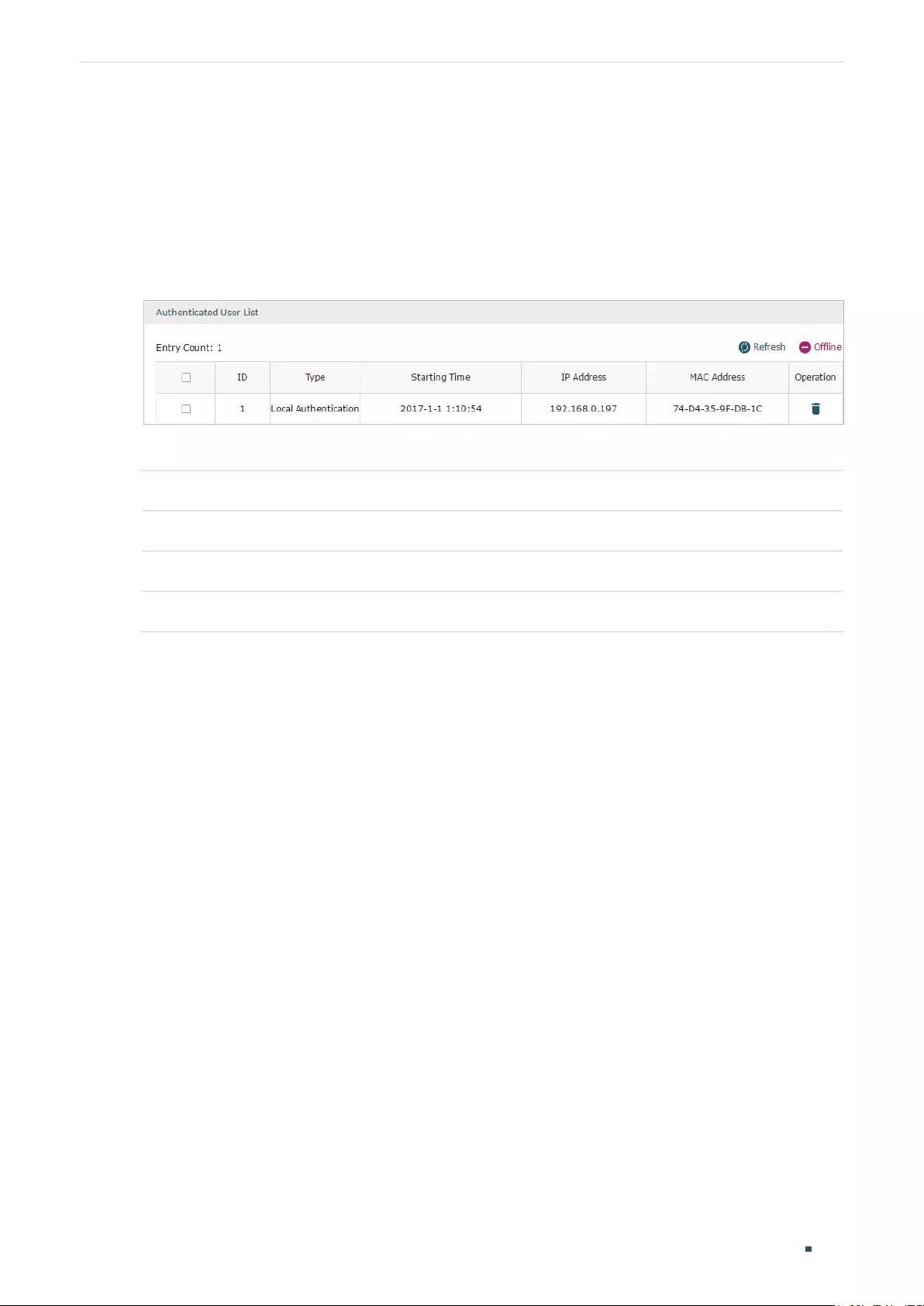
User Guide 180
Configuring Authentication Viewing the Authentication Status
6 Viewing the Authentication Status
Choose the menu Authentication > Authentication Status > Authentication Status to
load the following page.
Figure 6-1 Viewing the Authentication Status
Here you can view the clients that pass the portal authentication.
Type Displays the authentication type of the client.
Starting Time Displays the starting time of the authentication.
IP Address Displays the client’s IP address.
MAC Address Displays the client’s MAC address.
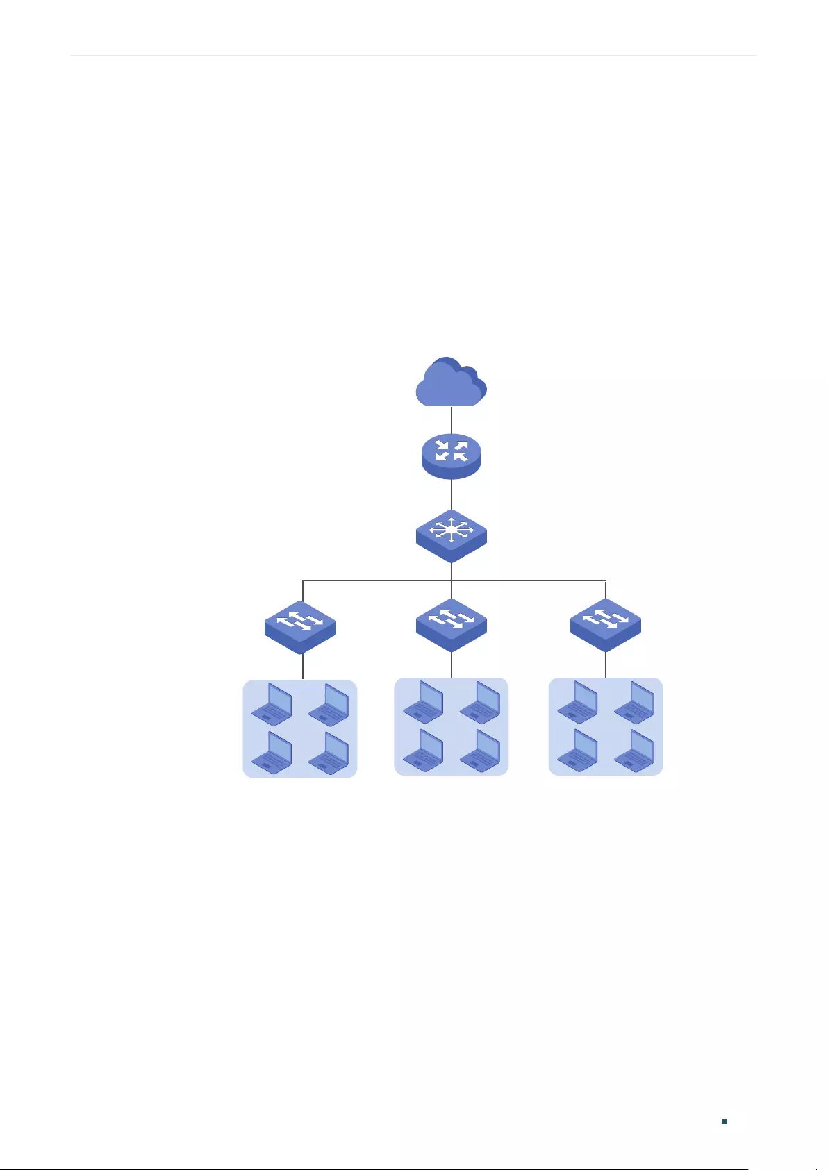
Configuring Authentication Configuration Example
User Guide 181
7 Configuration Example
Here we take the application of Local Authentication as an example.
7.1 Network Requirements
A hotel needs to offer internet service to the guests and push hotel advertisement. For
network security, only the authorized guests can access the internet.
Figure 7-1 Network Topology
Internet
Router
Clients Clients Clients
Core Switch
Access SwitchAccess Switch
7.2 Configuration Scheme
For the hotel does not have an external Web server or Authentication server, it is
recommended to choose Local Authentication to meet this requirement.
To control the guests’ internet access, you can create local user accounts for the
guests. The guests need to use the accounts assigned to them to get authenticated,
then can visit the internet. The other people cannot visit the internet through the hotel’s
network without authentication accounts.

User Guide 182
Configuring Authentication Configuration Example
To push hotel advertisement, you can simply customize the authentication page by set
the background picture and the welcome information.
7.3 Configuration Procedures
1) Enable Portal Authentication, choose the authentication type as Local Authentication,
and customize the authentication page.
2) Create the authentication accounts for the guests.
7.3.1 Configuring the Authentication Page
Choose the menu Authentication > Authentication Settings > Web Authentication to
load the following page.
1) Enable portal authentication, and keep the Idle Timeout and Portal Authentication Port
as default settings.
Figure 7-2 Enable Portal Authentication
2) Choose the Authentication Page as Custom page, pick a picture of the hotel as the
background picture on the authentication page, and specify the welcome information
and copyright.
Figure 7-3 Customize the authentication page
3) Choose the Authentication Type as Local Authentication, and configure the parameters
of expiration reminder. Then click Save.

Configuring Authentication Configuration Example
User Guide 183
Figure 7-4 Configure the authentication type and expiration reminder
7.3.2 Configuring Authentication Accounts for the Guests
Choose the menu Authentication > User Management > User Management to load the
following page.
Here we take the configuration of Formal User account as an example. We create an
account for the guests of room 101. The username is Room101 and the password is
123456, and at most three guests can use this account to authenticate. Then click OK.
Figure 7-5 Configure the Account for the guests
After all the configuration finished, the guest can use the account to authenticate and
access the internet after the authentication succeeded.

Part 10
Managing Services
CHAPTERS
1. Services
2. Dynamic DNS Configurations
3. UPnP Configuration
4. Conguration Example for Dynamic DNS

Managing Services Services
User Guide 185
1 Services
1.1 Overview
The Services module incorporates two functions, Dynamic DNS (DDNS) and UPnP (Universal
Plug and Play) to provide convenient network services.
1.2 Support Features
Dynamic DNS
Nowadays, network protocols such as PPPoE and DHCP are widely employed by ISPs to
assign public IP addresses to users. The use of these protocols can cause the user’s public
IP address to change dynamically. DDNS is an internet service that ensures a fixed domain
name can be used to access a network with a varying public IP address. This means the
user’s network can be more easily accessed by internet hosts.
UPnP
With the development of networking and advanced computing techniques, greater
numbers of devices feature in networks. UPnP is designed to solve the problem of
communication between these network devices. UPnP function allows devices dynamically
discover and communicate with each other without additional configurations. For example,
it allows the download of P2P software without opening ports.

User Guide 186
Managing Services Dynamic DNS Configurations
2 Dynamic DNS Configurations
With Dynamic DNS configurations, you can:
Configure and view Peanuthull DDNS
Configure and view Comexe DDNS
Configure and view DynDNS
Configure and view NO-IP DDNS
2.1 Configure and View Peanuthull DDNS
Choose the menu Service > Dynamic DNS > Peanuthull and click Add to load the following
page.
Figure 2-1 Configure Peanuthull DDNS
Follow these steps to configure Peanuthull DDNS.
1) Click Go to register to visit the official website of Peanuthull, register an account and a
domain name.
2) Configure the following parameters and click OK.
Interface Select the interface for the DDNS service.
Account Name Enter the account name of your DDNS account. You can click Go to register to
visit the official website of Peanuthull to register an account.
Password Enter the password of your DDNS account.
Update Interval Specify the Update Interval that the device dynamically updates IP addresses for
registered domain names.
Status Check the box to enable the DDNS service.

Managing Services Dynamic DNS Configurations
User Guide 187
3) View the DDNS status.
Figure 2-2 View the Status of Peanuthull DDNS
Status Displays whether the corresponding DDNS service is enabled.
Service Status Displays the current status of DDNS service.
Offline: DDNS service is offline.
Connecting: DDNS client is connecting to the server.
Online: DDNS is working normally.
Incorrect account name or password: The account name or password is
incorrect.
Domain Name Displays the Domain Names obtained from the DDNS server.
Service Type Displays the DDNS service type, including Professional service and Standard
service.
2.2 Configure and View Comexe DDNS
Choose the menu Service > Dynamic DNS > Comexe and click Add to load the following
page.
Figure 2-3 Configure Comexe DDNS
Follow these steps to configure Comexe DDNS.
1) Click Go to register to visit the official website of Comexe, register an account and a
domain name.

User Guide 188
Managing Services Dynamic DNS Configurations
2) Configure the following parameters and click OK.
Interface Select the interface for the DDNS service.
Account Name Enter the account name of your DDNS account. You can click Go to register to
visit the official website of Comexe to register an account.
Password Enter the password of your DDNS account.
Update Interval Specify the Update Interval that the device dynamically updates IP addresses for
registered domain names.
Status Check the box to enable the DDNS service.
3) View the DDNS status.
Figure 2-4 View the Status of Comexe DDNS
Status Displays whether the corresponding DDNS service is enabled.
Service Status Displays the current status of DDNS service.
Offline: DDNS service is offline.
Connecting: DDNS client is connecting to the server.
Online: DDNS is working normally.
Incorrect account name or password: The account name or password is
incorrect.
Domain Name Displays the Domain Names obtained from the DDNS server.
2.3 Configure and View DynDNS
Choose the menu Service > Dynamic DNS > DynDNS and click Add to load the following
page.

Managing Services Dynamic DNS Configurations
User Guide 189
Figure 2-5 Configure DynDNS
Follow these steps to configure DynDNS.
1) Click Go to register to visit the official website of DynDNS and register an account and
a domain name.
2) Configure the following parameters and click OK.
Interface Select the interface for the DDNS service.
Account Name Enter the account name of your DDNS account. You can click Go to register to
visit the official website of DynDNS to register an account.
Password Enter the password of your DDNS account.
Domain Name Specify the domain name that you registered with your DDNS service provider.
Update Interval Specify the Update Interval that the device dynamically updates IP addresses for
registered domain names.
Status Check the box to enable the DDNS service.
3) View the DDNS status.
Figure 2-6 View the Status of DynDNS
Status Displays whether the corresponding DDNS service is enabled.

User Guide 190
Managing Services Dynamic DNS Configurations
Service Status Displays the current status of DDNS service.
Offline: DDNS service is offline.
Connecting: DDNS client is connecting to the server.
Online: DDNS is working normally.
Incorrect account name or password: The account name or password is
incorrect.
Incorrect domain name: The domain name is incorrect.
Domain Name Displays the Domain Names obtained from the DDNS server.
2.4 Configure and View NO-IP DDNS
Choose the menu Service > Dynamic DNS > NO-IP and click Add to load the following
page.
Figure 2-7 View NO-IP DDNS
Follow these steps to configure NO-IP DDNS.
1) Click Go to register to visit the official website of NO-IP and register an account and a
domain name.
2) Configure the following parameters and click OK.
Interface Select the interface for the DDNS service.
Account Name Enter the account name of your DDNS account. You can click Go to register to
visit the official website of NO-IP to register an account.
Password Enter the password of your DDNS account.
Domain Name Specify the domain name that you registered with your DDNS service provider.
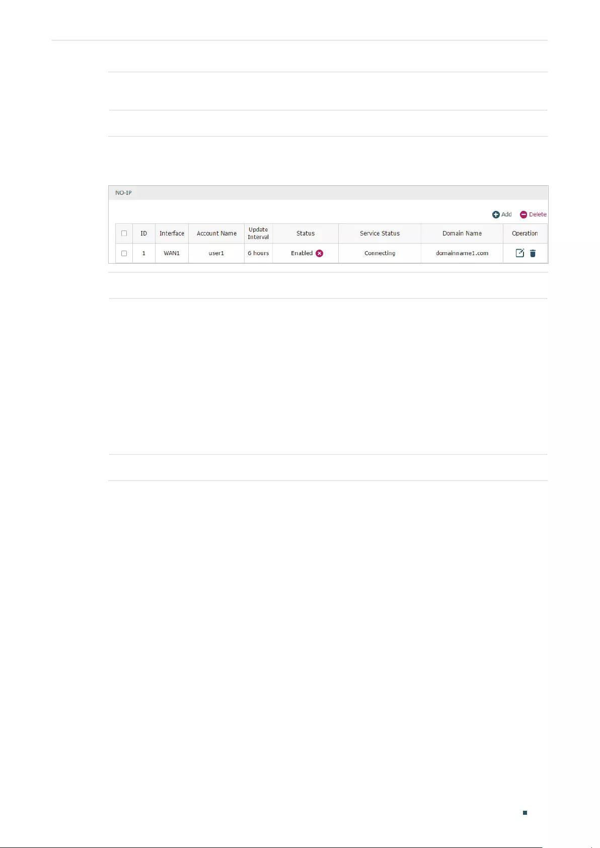
Managing Services Dynamic DNS Configurations
User Guide 191
Update Interval Specify the Update Interval that the device dynamically updates IP addresses for
registered domain names.
Status Check the box to enable the DDNS service.
3) View the DDNS status.
Figure 2-8 View the Status of NO-IP DDNS
Status Displays whether the corresponding DDNS service is enabled.
Service Status Displays the current status of DDNS service.
Offline: DDNS service is offline.
Connecting: DDNS client is connecting to the server.
Online: DDNS is working normally.
Incorrect account name or password: The account name or password is
incorrect.
Incorrect domain name: The domain name is incorrect.
Domain Name Displays the Domain Names obtained from the DDNS server.
User Guide 192
Managing Services UPnP Configuration
3 UPnP Configuration
Choose the menu Service > UPnP to load the following page.
Figure 3-1 Configure UPnP Function
Follow these steps to configure UPnP function:
1) In the General section, enable the UPnP function and select the interface. Then click
Save.
Enable UPnP Check the box to enable the UPnP function.
Interface Select the interface for the UPnP function.
2) (Optional) In the UPnP Portmap List section, view the portmap list.
Description Displays the description of the application using UPnP protocol.
Protocol Displays the protocol type used in the process of UPnP.
Interface Displays the interface used in the process of UPnP.
IP Address Displays the IP address of the local host.
External Port Displays the external port that is opened for the application by the router.
Internal Port Displays the internal port that is opened for the application by the local host.
Status Displays the status of the corresponding UPnP entry.
Enabled: The mapping is active.
Disabled: The mapping is inactive.

Managing Services Configuration Example for Dynamic DNS
User Guide 193
4 Configuration Example for Dynamic DNS
4.1 Network Requirement
Host A gets internet services from an ISP (Internet Service Provider) via a PPPoE dial-up
connection. The user wants to visit the router’s web management interface using another
host on the internet.
Figure 4-1 Network Topology
Internet
Internet HostHost A Router
4.2 Configuration Scheme
For security management, the internet hosts attempting to manage the router must be
permitted by the router. Remote Management is used to manage the IP addresses of these
hosts.
Because the user uses PPPoE to access to the network, the public IP address of the router
may be changed each time the dial-up connection is established. When the public IP
address of the router changes, DDNS service ensures the DNS server rebinds the current
domain name to the new IP address. This means the user can always reach the router using
the same domain name, even if the public IP address has been changed.
4.3 Configuration Procedure
4.3.1 Specifying the IP Address of the Host
Before configuring DDNS, it is required to specify the IP address of the internet host
for remote management. For details, go to System Tools > Admin Setup > Remote
Management page.
4.3.2 Configuring the DDNS function
There are four DDNS servers supported by the router, we take Peanuthull DNS as an
example here.
1) Choose the menu Services > Dynamic DNS > Peanuthull and click Add to load the
following page. Click Go to register to register a domain name on the official website of
Peanuthull.

User Guide 194
Managing Services Configuration Example for Dynamic DNS
Figure 4-2 Registering a Domain Name
2) Set the Interface as WAN1, set the Update Interval as 6 hours, and enter the Account
Name and Password previously registered before. Click OK.
Figure 4-3 Specifying Peanuthull DDNS Parameters

Part 11
System Tools
CHAPTERS
1. System Tools
2. Admin Setup
3. Management
4. SNMP
5. Diagnostics
6. Time Settings
7. System Log

User Guide 196
System Tools System Tools
1 System Tools
1.1 Overview
The System Tools module provides several system management tools for users to manage
the router.
1.2 Support Features
Admin Setup
Admin Setup is used to configure the parameters for users’ login. With this function, you
can modify the login account, specify the IP subnet and mask for remote access and
specify the HTTP and HTTPS server port.
Management
The Management section is used to manage the firmware and the configuration file of the
router. With this function, you can reset the router, backup and restore the configuration
file, reboot the router and upgrade the firmware.
SNMP
SNMP (Simple Network Management Protocol) is a standard network management
protocol. It helps network managers to configure and monitor network devices. With SNMP,
network managers can view and modify network device information, detect and analyze
network error, and so on. The router supports SNMPv1 and SNMPv2.
Diagnostics
Diagnostics is used to detect network errors and equipment failures. With this function,
you can test the connectivity of the network with ping or traceroute command and inspect
the router under the help of technicians.
Time Settings
Time Settings is used to configure the system time and the daylight saving time.
System Log
System Log is used to view the system log of the router. You can also configure the router
to send the log to a server.

System Tools Admin Setup
User Guide 197
2 Admin Setup
In Admin Setup module, you can configure the following features:
Admin Setup
Remote Management
System Settings
2.1 Admin Setup
Choose the menu System Tools > Admin Setup > Admin Setup to load the following page.
Figure 2-1 Modifying the Admin Account
In the Account section, configure the following parameters and click Save to modify the
admin account
Old Username Enter the old username.
Old Password Enter the old password.
New Username Enter a new username.
New Password Enter a new password.
Confirm New
Password
Re-enter the new password for confirmation.

User Guide 198
System Tools Admin Setup
2.2 Remote Management
Choose the menu System Tools > Admin Setup > Remote Management and click Add to
load the following page.
Figure 2-2 Configuring Remote Management
In the Remote Management section, configure the following parameters and click OK to
specify the IP subnet and mask for remote management.
Subnet/Mask Enter the IP Subnet and Mask of the remote host.
Status Check the box to enable the remote management function for the remote host.
2.3 System Setting
Choose the menu System Tools > Admin Setup > System Settings to load the following
page.
Figure 2-3 Configuring System Settings
In the Settings section, configure the following parameters and click Save.

System Tools Admin Setup
User Guide 199
HTTP Server
Port
Enter the http server port for web management. The port number should be different
from other servers’. The default setting is 80. After changing the http server port, you
should access the interface by using IP address and the port number in the format of
192.168.0.1:1600.
Redirect HTTP
to HTTPS
Check the box to enable the function, then you will access the web management
interface by HTTPS protocol instead of HTTP protocol.
HTTPS Server
Port
Enter the https server port for web management. The port number should be different
from other servers’. The default setting is 443. After changing the https server port,
you should access the interface by using IP address and the port number in the
format of https://192.168.0.1:1800.
Web Idle
Timeout
Enter a session timeout time for the device. The web session will log out for security if
there is no operation within the session timeout time.
User Guide 200
System Tools Management
3 Management
In Management module, you can configure the following features:
Factory Default Restore
Backup & Restore
Reboot
Firmware Upgrade
3.1 Factory Default Restore
Choose the menu System Tools > Management > Factory Default Restore to load the
following page.
Figure 3-1 Reseting the Device
Click Factory Restore to reset the device.
3.2 Backup & Restore
Choose the menu System Tools > Management > Backup & Restore to load the following
page.
Figure 3-2 Backup & Restore Page
Choose the corresponding operation according to your need:
System Tools Management
User Guide 201
1) In the Backup section, click Backup to save your current configuration as a
configuration file and export the file to the host.
2) In the Restore section, select one configuration file saved in the host and click Restore
to import the saved configuration to your router.
3.3 Reboot
Choose the menu System Tools > Management > Reboot to load the following page.
Figure 3-3 Rebooting the Device
Click Reboot to reboot the device.
3.4 Firmware Upgrade
Choose the menu System Tools > Management > Firmware Upgrade to load the following
page.
Figure 3-4 Configure System Settings
Select one firmware file and click Upgrade to upgrade the firmware of the device.

User Guide 202
System Tools SNMP
4 SNMP
Choose the menu System Tools > SNMP > SNMP to load the following page.
Figure 4-1 Configuring SNMP
Follow these steps to configure the SNMP function:
1) Check the box to enable the SNMP function.
2) Configure the following parameters and click Save.
Contact Enter the textual identification of the contact person for this the device, for
example, contact or e-mail address.
Device Name Enter a name for the device.
Location Enter the location of the device. For example, the name can be composed of the
building, floor number, and room location.
Get Community Specify the community that has read-only access to the device’s SNMP
information.
Get Trusted
Host
Enter the IP address that can serve as Get Community to read the SNMP
information of this device.
Set Community Specify the community who has the read and write right of the device’s SNMP
information.
Set Trusted
Host
Enter the IP address that can serve as Set Community to read and write the SNMP
information of this device.

System Tools Diagnostics
User Guide 203
5 Diagnostics
In Diagnostics module, you can configure the following features:
Diagnostics
Remote Assistance
5.1 Diagnostics
Ping and traceroute are both used to test the connectivity between two devices in the
network. In addition, ping can show the roundtrip time between the two devices directly
and traceroute can show the IP address of routers along the route path.
5.1.1 Configuring Ping
Choose the menu System Tools > Diagnostics > Diagnostics to load the following page.
Figure 5-1 Configuring Diagnostics
Follow these steps to configure Diagnostics:
1) In Diagnostics section, select Ping and configure the following parameters.
Diagnostic Tool Select Ping to test the connectivity between the router and the desired device.

User Guide 204
System Tools Diagnostics
Destination IP/
Domain Name
Enter the IP address or the domain name that you want to ping or tracert.
Interface Select the interface that sends the detection packets.
2) (Optional) Click Advanced and the following section will appear.
Figure 5-2 Advanced Parameters for Ping Method
Ping Count Specify the count of the test packets to be sent during the ping process.
Ping Packet Size Specify the size of the test packets to be sent during the ping process.
3) Click Start.
5.1.2 Configuring Traceroute
Choose the menu System Tools > Diagnostics > Diagnostics to load the following page.
Figure 5-3 Configuring Diagnostics
Follow these steps to configure Diagnostics:
System Tools Diagnostics
User Guide 205
1) In Diagnostics section, select Traceroute and configure the following parameters.
Diagnostic Tool Select Traceroute to test the connectivity between the router and the desired
device.
Destination IP/
Domain Name
Enter the IP address or the domain name that you want to ping or tracert.
Interface Select the interface that sends the detection packets.
2) (Optional) Click Advanced and the following section will appear.
Figure 5-4 Advanced Parameters for Traceroute Method
Traceroute MAX
TTL
Specify the traceroute max TTL (Time To Live) during the traceroute process. It is
the maximum number of the route hops the test packets can pass through.
3) Click Start.
5.2 Remote Assistance
Note:
Please make contact with the technicians brfore trying to use this function.
Choose the menu System Tools > Diagnostics > Remote Assistance to load the following
page.
Figure 5-5 Remote Assistance Page
1) In the Remote Assistance section, check the box and click Save to enable the remote
assistance function and then the technicians can access your router and help to solve
the problems by SSH.
2) In the Diagnostic Information section, click Export to download a binary (.bin) file
containing helpful information, and send it to the technicians for help.

User Guide 206
System Tools Time Settings
6 Time Settings
In Time Settings module, you can configure the following features:
System Time
Daylight Saving Time
6.1 Setting the System Time
Choose one method to set the system time.
6.1.1 Getting time from the Internet Automatically
Choose the menu System Tools > Time Settings > Time Settings to load the following
page.
Figure 6-1 Getting Automatically from the Internet
In the Time Settings section, configure the following parameters and click Save.
Current Time Displays the current system time.
Time Config Select Get automatically from the Internet to get the system time from the NTP
server.
Time Zone Select the time zone the device is in.
Primary NTP
Server
Enter the IP address of the Primary NTP server.
Secondary NTP
Server
Enter the IP address of the Secondary NTP server.
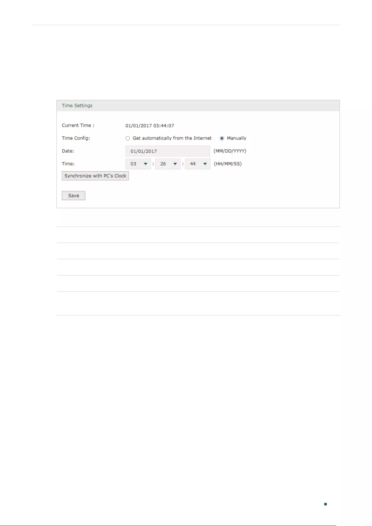
System Tools Time Settings
User Guide 207
6.1.2 Setting the System Time Manually
Choose the menu System Tools > Time Settings > Time Settings to load the following
page.
Figure 6-2 Setting the System Time Manually
In the Time Settings section, configure the following parameters and click Save.
Current Time Displays the current system time.
Time Config Select Manually to set the system time manually.
Date Specify the date of the system.
Time Specify the time of the system.
Synchronize
with PC’s Clock
Synchronize the system time of the router with PC’s clock.
6.2 Setting the Daylight Saving Time
Choose one method to set the daylight saving time.
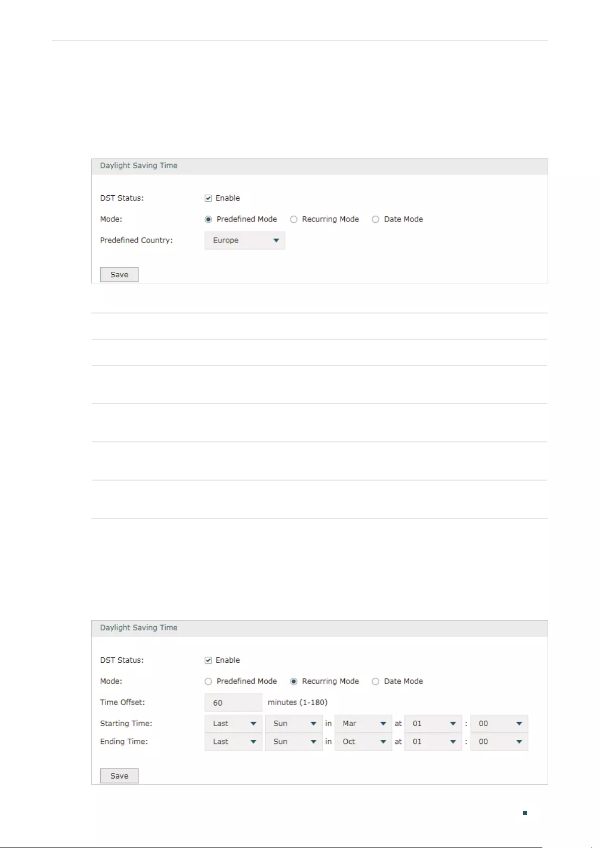
User Guide 208
System Tools Time Settings
6.2.1 Predefined Mode
Choose the menu System Tools > Time Settings > Time Settings to load the following
page.
Figure 6-3 Predefined Mode Page
In the Daylight Saving Time section, select one predefined DST schedule and click Save.
DST Status Check the box to enable the DST function.
Mode Select Predefined Mode to choose a predefined daylight saving time.
USA Select the Daylight Saving Time of the USA. It is from 2: 00 a.m. on the Second Sunday
in March to 2:00 a.m. on the First Sunday in November
Europe Select the Daylight Saving Time of Europe. It is from 1:00 a.m. on the Last Sunday in
March to 1:00 a.m. on the Last Sunday in October.
Australia Select the Daylight Saving Time of Australia. It is from 2:00 a.m. on the First Sunday in
October to 3:00 a.m. on the First Sunday in April.
New Zealand Select the Daylight Saving Time of New Zealand. It is from 2:00 a.m. on the Last
Sunday in September to 3:00 a.m. on the First Sunday in April.
6.2.2 Recurring Mode
Choose the menu System Tools > Time Settings > Time Settings to load the following
page.
Figure 6-4 Recurring Mode Page

System Tools Time Settings
User Guide 209
In the Daylight Saving Time section, configure the following parameters and click Save.
DST Status Check the box to enable the DST function.
Mode Select Recurring Mode to specify a cycle time range for the daylight saving time. This
configuration will take effects every year.
Time Offset Specify the time added in minutes when Daylight Saving Time takes effect.
Starting Time Specify the starting time of Daylight Saving Time. The starting time is relative to
standard time.
Ending Time Specify the ending time of Daylight Saving Time. The ending time is relative to daylight
saving time.
6.2.3 Date Mode
Choose the menu System Tools > Time Settings > Time Settings to load the following
page.
Figure 6-5 Date Mode Page
In the Daylight Saving Time section, select one predefined DST schedule and click Save.
DST Status Check the box to enable the DST function.
Mode Select Date Mode to specify an absolute time range for the daylight saving time.
Time Offset Specify the time added in minutes when Daylight Saving Time takes effect.
Starting Time Specify the starting time of Daylight Saving Time. The starting time is relative to
standard time.
Ending Time Specify the ending time of Daylight Saving Time. The ending time is relative to daylight
saving time.

User Guide 210
System Tools System Log
7 System Log
Choose the menu System Tools > System Log > System Log to load the following page.
Figure 7-1 System Log Page
Follow these steps to view the system log:
1) In the Log Settings section, configure the following parameters and click Save.
Enable Auto-
refresh
Check the box to enable this function and the page will refresh automatically
every 10 seconds.

System Tools System Log
User Guide 211
Severity Enable Severity and specify the importance of the logs you want to view in the log
list.
ALL Level: Logs of all levels.
EMERGENCY: Errors that render the router unusable, such as hardware errors.
ALERT: Errors that must be resolved immediately, such as flash write errors.
CRITICAL: Errors that put the system at risk, such as a failure to release memory.
ERROR: Generic errors.
WARNING: Warning messages, such as WinNuke attack warnings.
NOTICE: Important notifications, such as IKE policy mismatches.
INFO: Informational messages.
DEBUG: Debug-level notifications, such as when the router receives a DNS
packet.
Send Log Enable the Send Log function and then the newly generated logs will be sent to
the specified server.
Server IP Specify the IP address of the server that the logs will be sent to.
2) (Optional) Click Save Log to save the current logs to the host.

COPYRIGHT & TRADEMARKS
Specifications are subject to change without notice. is a registered trademark
of TP-Link Technologies Co., Ltd. Other brands and product names are trademarks or
registered trademarks of their respective holders.
No part of the specifications may be reproduced in any form or by any means or used to
make any derivative such as translation, transformation, or adaptation without permission
from TP-Link Technologies Co., Ltd. Copyright © 2018 TP-Link Technologies Co., Ltd. All
rights reserved.
http://www.tp-link.com
FCC STATEMENT
This equipment has been tested and found to comply with the limits for a Class A digital
device, pursuant to part 15 of the FCC Rules. These limits are designed to provide
reasonable protection against harmful interference when the equipment is operated in a
commercial environment. This equipment generates, uses, and can radiate radio frequency
energy and, if not installed and used in accordance with the instruction manual, may cause
harmful interference to radio communications. Operation of this equipment in a residential
area is likely to cause harmful interference in which case the user will be required to correct
the interference at his own expense.
This device complies with part 15 of the FCC Rules. Operation is subject to the following
two conditions:
1) This device may not cause harmful interference.
2) This device must accept any interference received, including interference that may
cause undesired operation.
Any changes or modifications not expressly approved by the party responsible for
compliance could void the user’s authority to operate the equipment.
CE Mark Warning
This is a class A product. In a domestic environment, this product may cause radio
interference, in which case the user may be required to take adequate measures.
TP-Link hereby declares that the device is in compliance with the essential requirements
and other relevant provisions of directives 2014/30/EU, 2014/35/EU, 2009/125/EC and
2011/65/EU.
The original EU declaration of conformity may be found at http://www.tp-link.com/en/ce

Canadian Compliance Statement
This device complies with Industry Canada license-exempt RSSs. Operation is subject to
the following two conditions:
1) This device may not cause interference, and
2) This device must accept any interference, including interference that may cause
undesired operation of the device.
Le présent appareil est conforme aux CNR d’Industrie Canada applicables aux appareils
radio exempts de licence. L’exploitation est autorisée aux deux conditions suivantes :
1) l’appareil ne doit pas produire de brouillage;
2) l’utilisateur de l’appareil doit accepter tout brouillage radioélectrique subi, meme si le
brouillage est susceptible d’en compromettre le fonctionnement.
Industry Canada Statement
CAN ICES-3 (A)/NMB-3(A)
NCC Notice
注意!
依據 低功率電波輻射性電機管理辦法
第十二條 經型式認證合格之低功率射頻電機,非經許可,公司、商號或使用者均不得擅自變
更頻率、加大功率或變更原設計之特性或功能。
第十四條 低功率射頻電機之使用不得影響飛航安全及干擾合法通行;經發現有干擾現象時,
應立即停用,並改善至無干擾時方得繼續使用。前項合法通信,指依電信規定作業之無線電信。
低功率射頻電機需忍受合法通信或工業、科學以及醫療用電波輻射性電機設備之干擾。
BSMI Notice
安全諮詢及注意事項
•請使用原裝電源供應器或只能按照本產品注明的電源類型使用本產品。
•清潔本產品之前請先拔掉電源線。請勿使用液體、噴霧清潔劑或濕布進行清潔。
•注意防潮,請勿將水或其他液體潑灑到本產品上。
•插槽與開口供通風使用,以確保本產品的操作可靠並防止過熱,請勿堵塞或覆蓋開口。
•請勿將本產品置放於靠近熱源的地方。除非有正常的通風,否則不可放在密閉位置中。
•請不要私自打開機殼,不要嘗試自行維修本產品,請由授權的專業人士進行此項工作。

此為甲類資訊技術設備,于居住環境中使用時,可能會造成射頻擾動,在此種情況下,使用者
會被要求採取某些適當的對策。
限用物質含有情況標示聲明書
產品元件
名稱
限用物質及其化學符號
鉛
Pb
鎘
Cd
汞
Hg
六價鉻
CrVI
多溴聯苯
PBB
多溴二苯醚
PBDE
PCB ○ ○ ○ ○ ○ ○
外殼 ○ ○ ○ ○ ○ ○
電源供應
板—○ ○ ○ ○ ○
備考1.»超出0.1 wt %» 及 «超出0.01 wt %» 系指限用物質之百分比含量超出百分比含量基準值。
備考2.»○»系指該項限用物質之百分比含量未超出百分比含量基準值。
備考3.»-» 系指該項限用物質為排除項目。
Продукт сертифіковано згідно с правилами системи УкрСЕПРО на відповідність
вимогам нормативних документів та вимогам, що передбачені чинними законодавчими
актами України.
Safety Information
Keep the device away from water, fire, humidity or hot environments.
Do not attempt to disassemble, repair, or modify the device.
Do not use damaged charger or USB cable to charge the device.
Do not use any other chargers than those recommended
Please read and follow the above safety information when operating the device. We cannot
guarantee that no accidents or damage will occur due to improper use of the device.
Please use this product with care and operate at your own risk.
この装置は、クラス A 情報技術装置です。この装置を家庭環境で使用すると電波妨害を引き
起こすことがあります。この場合には使用者が適切な対策を講ずるよう要求されることがあ
ります。 VCCI-A

Explanation of the symbols on the product label
Symbol Explanation
AC voltage
Indoor use only.
RECYCLING
This product bears the selective sorting symbol for Waste electrical and electronic
equipment (WEEE). This means that this product must be handled pursuant to
European directive 2012/19/EU in order to be recycled or dismantled to minimize
its impact on the environment.
User has the choice to give his product to a competent recycling organization or to
the retailer when he buys a new electrical or electronic equipment.

TL-R600VPN
Gigabit Broadband VPN Router
REV2.0.0
1910010932

COPYRIGHT & TRADEMARKS
Specifications are subject to change without notice. is a registered trademark
of TP-LINK TECHNOLOGIES CO., LTD. Other brands and product names are trademarks or
registered trademarks of their respective holders.
No part of the specifications may be reproduced in any form or by any means or used to make any
derivative such as translation, transformation, or adaptation without permission fromTP-LINK
TECHNOLOGIES CO., LTD. Copyright © 2013 TP-LINK TECHNOLOGIES CO., LTD. All rights
reserved.
http://www.tp-link.com
FCC STATEMENT
This equipment has been tested and found to comply with the limits for a Class A digital device,
pursuant to part 15 of the FCC Rules. These limits are designed to provide reasonable protection
against harmful interference when the equipment is operated in a commercial environment. This
equipment generates, uses, and can radiate radio frequency energy and, if not installed and used
in accordance with the instruction manual, may cause harmful interference to radio
communications. Operation of this equipment in a residential area is likely to cause harmful
interference in which case the user will be required to correct the interference at his own expense.
This device complies with part 15 of the FCC Rules. Operation is subject to the following two
conditions:
1) This device may not cause harmful interference.
2) This device must accept any interference received, including interference that may
cause undesired operation.
Any changes or modifications not expressly approved by the party responsible for compliance
could void the user’s authority to operate the equipment.
CE Mark Warning
This is a class A product. In a domestic environment, this product may cause radio interference, in
which case the user may be required to take adequate measures.
Продукт сертифіковано згідно с правилами системи УкрСЕПРО на відповідність вимогам
нормативних документів та вимогам, що передбачені чинними законодавчими актами
України.

Safety Information
z When product has power button, the power button is one of the way to shut off the product;
When there is no power button, the only way to completely shut off power is to disconnect the
product or the power adapter from the power source.
z Don’t disassemble the product, or make repairs yourself. You run the risk of electric shock
and voiding the limited warranty. If you need service, please contact us.
z Avoid water and wet locations.
安全諮詢及注意事項
●請使用原裝電源供應器或只能按照本產品注明的電源類型使用本產品。
●清潔本產品之前請先拔掉電源線。請勿使用液體、噴霧清潔劑或濕布進行清潔。
●注意防潮,請勿將水或其他液體潑灑到本產品上。
●插槽與開口供通風使用,以確保本產品的操作可靠並防止過熱,請勿堵塞或覆蓋開口。
●請勿將本產品置放於靠近熱源的地方。除非有正常的通風,否則不可放在密閉位置中。
●請不要私自打開機殼,不要嘗試自行維修本產品,請由授權的專業人士進行此項工作。
此為甲類資訊技術設備,于居住環境中使用時,可能會造成射頻擾動,在此種情況下,使用者會被
要求採取某些適當的對策。
This product can be used in the following countries:
AT BG BY CA CZ DE DK EE
ES FI FR GB GR HU IE IT
LT LV MT NL NO PL PT RO
RU SE SK TR UA

Package Contents
The following items should be found in your box:
¾ One TL-R600VPN SafeStream Gigabit Broadband VPN Router
¾ One Power Cord
¾ Resource CD
Note:
)
1) The provided power cord may be different due to
2) Make sure that the package contains the above items. If any of the listed items are
damaged or missing, please contact your distributor.
local power specifications.
Conventions
The router or TL-R600VPN mentioned in this guide stands for TL-R600VPN SafeStream Gigabit
Broadband VPN Router without any explanation.

CONTENTS
Chapter 1. Introduction ……………………………………………………………………………. 1
1.1 Overview of the Router …………………………………………………………………………………….. 1
1.2 Features…………………………………………………………………………………………………………. 1
1.3 Conventions……………………………………………………………………………………………………. 1
Chapter 2. Hardware Installation ………………………………………………………………. 2
2.1 Panel Layout…………………………………………………………………………………………………… 2
2.1.1 The Front Panel………………………………………………………………………………………………….2
2.1.2 The Rear Panel …………………………………………………………………………………………………. 2
2.2 System Requirements ……………………………………………………………………………………… 3
2.3 Installation Environment Requirements ………………………………………………………………. 3
2.4 Connect to Ground ………………………………………………………………………………………….. 3
2.5 Connecting the Router……………………………………………………………………………………… 4
Chapter 3. Quick Installation Guide ………………………………………………………….. 5
3.1 Configure PC ………………………………………………………………………………………………….. 5
3.2 Login……………………………………………………………………………………………………………… 8
Chapter 4. Configuring the Router ………………………………………………………….. 12
4.1 Status…………………………………………………………………………………………………………… 12
4.2 Quick Setup ………………………………………………………………………………………………….. 14
4.3 Network………………………………………………………………………………………………………… 14
4.3.1 WAN ……………………………………………………………………………………………………………….14
4.3.2 LAN…………………………………………………………………………………………………………………23
4.3.3 MAC Clone ………………………………………………………………………………………………………24
4.4 DHCP…………………………………………………………………………………………………………… 25
4.4.1 DHCP Settings ………………………………………………………………………………………………… 25
4.4.2 DHCP Clients List…………………………………………………………………………………………….. 26
4.4.3 Address Reservation …………………………………………………………………………………………26
4.5 Forwarding……………………………………………………………………………………………………. 28
4.5.1 Virtual Servers………………………………………………………………………………………………….28
4.5.2 Port Triggering…………………………………………………………………………………………………. 30
4.5.3 DMZ………………………………………………………………………………………………………………..31
4.5.4 UPnP ………………………………………………………………………………………………………………32
4.6 Security…………………………………………………………………………………………………………33
4.6.1 Basic Security………………………………………………………………………………………………….. 33
4.6.2 Advanced Security ……………………………………………………………………………………………34
4.6.3 Local Management……………………………………………………………………………………………35
4.7 Access Control………………………………………………………………………………………………. 36
4.7.1 Rule ………………………………………………………………………………………………………………..36
4.7.2 Host ……………………………………………………………………………………………………………….. 38

4.7.3 Target ……………………………………………………………………………………………………………..39
4.7.4 Schedule …………………………………………………………………………………………………………40
4.8 IPsec VPN ……………………………………………………………………………………………………. 41
4.8.1 IKE………………………………………………………………………………………………………………….41
4.8.2 IPsec……………………………………………………………………………………………………………….43
4.8.3 SA List …………………………………………………………………………………………………………….46
4.9 PPTP VPN Server …………………………………………………………………………………………. 47
4.9.1 Server Settings………………………………………………………………………………………………… 47
4.9.2 Account Settings ………………………………………………………………………………………………47
4.9.3 Connection Status …………………………………………………………………………………………….48
4.10 Advanced Routing …………………………………………………………………………………………. 49
4.10.1 Static Routing …………………………………………………………………………………………………..49
4.10.2 System Routing Table ………………………………………………………………………………………. 50
4.11 Bandwidth Control …………………………………………………………………………………………. 51
4.11.1 Control Settings ………………………………………………………………………………………………..51
4.11.2 Rule List………………………………………………………………………………………………………….. 51
4.12 IP & MAC Binding ………………………………………………………………………………………….. 53
4.12.1 Binding Setting …………………………………………………………………………………………………53
4.12.2 ARP List………………………………………………………………………………………………………….. 55
4.13 Dynamic DNS ……………………………………………………………………………………………….. 55
4.13.1 Dyndns DDNS ………………………………………………………………………………………………….55
4.13.2 PeanutHull DDNS……………………………………………………………………………………………..56
4.13.3 Comexe DDNS ………………………………………………………………………………………………… 57
4.13.4 No-IP DDNS …………………………………………………………………………………………………….57
4.14 System Tools ………………………………………………………………………………………………… 58
4.14.1 Time Settings ………………………………………………………………………………………………….. 58
4.14.2 Diagnostic Tools ……………………………………………………………………………………………….60
4.14.3 Firmware…………………………………………………………………………………………………………. 61
4.14.4 Factory Defaults ……………………………………………………………………………………………….61
4.14.5 Backup and Restore …………………………………………………………………………………………. 62
4.14.6 Reboot …………………………………………………………………………………………………………….63
4.14.7 Password…………………………………………………………………………………………………………64
4.14.8 System Log …………………………………………………………………………………………………….. 64
4.14.9 Remote Management ……………………………………………………………………………………….. 65
4.14.10 Statistics ………………………………………………………………………………………………………….66
Appendix A: Specifications……………………………………………………………………….. 68
Appendix B: Preventing Lightning …………………………………………………………….. 69
Appendix C: FAQ………………………………………………………………………………………. 70
Appendix D: Glossary……………………………………………………………………………….. 74

TL-R600VPN SafeStream Gigabit Broadband VPN Router User Guide
Chapter 1. Introduction
1.1 Overview of the Router
The TL-R600VPN SafeStream Gigabit Broadband VPN Router from TP-LINK provides multiple
VPN protocols and high VPN performance. Abundant security strategies, such as SPI firewall,
protect your network against the attacks and Access Control, provide online behavior
management. Anymore, web-based management makes the network setup be an easy work. It’s
really a cost-effective and reliable VPN solution for chain stores and branch offices.
1.2 Features
¾ Complies with IEEE 802.3, 802.3u , 802.3x standards
¾ Supports Bandwidth Control
¾ Built-in NAT and DHCP server supporting static IP address distributing
¾ Supports Virtual Server, Port Triggering, and DMZ host
¾ Built-in firewall supporting IP address filtering, Domain Name filtering, and MAC address filtering
¾ Supports connecting/disconnecting Internet at a specified time of day
¾ Supports access control, allowing parents and network administrators to establish restricted
access policies based on the time of day for children or staff
¾ Supports TCP/IP, PPPoE, DHCP, ICMP, NAT, SNTP
¾ Supports UPnP, Dynamic DNS, Static Routing, VPN pass-through
¾ Supports Traffic Statistics
¾ Supports IP & MAC Binding
¾ Supports ICMP-FLOOD, UDP-FLOOD, TCP-SYN-FLOOD filter
¾ Ignores Ping packets from WAN or LAN ports
¾ Supports firmware upgrade
¾ Supports Remote and Web management
¾ Supports IPsec VPN and PPTP Server
1.3 Conventions
Parameters provided in the pictures are just references for setting up the product, which may
differ from the actual situation.
You can set the parameters according to your demand.
1

SafeStream Gigabit Broadband VPN Router User GuideTL-R600VPN
Chapter 2. Hardware Installation
2.1 Panel Layout
2.1.1 The Front Panel
The router’s LEDs are located on the front panel (Viewed from left to right).
Figure 2-1
LED Descriptions:
Name Status Indication
PWR
Not lit The router is powered off.
Lit up (Green) The router is powered on.
Not lit The router has a hardware error.
Lit up (Green) The router has a hardware error.
SYS
Flashing
(Green)
Not lit There is no device linked to the corresponding port.
Lit up
(Green/Yellow)
WAN, LAN
Flashing
(Green/Yellow)
2.1.2 The Rear Panel
The router works properly.
There is a device linked to the corresponding port but no
activity. (Green light indicates the linked device is running at
1000Mbps, and yellow indicates the linked device is running
at 10/100Mbps.)
The corresponding port is transmitting or receiving data.
(Green light indicates the linked device is running at
1000Mbps, and yellow indicates the linked device is running
at 10/100Mbps.)
The rear panel contains the following features (Viewed from left to right).
Figure 2-2
¾ AC power receptacle: Connect the female of the power cord head here, and the male head
to the AC power outlet.
¾ RESET: Use the button to restore the router to the factory defaults.
There are two ways to reset the router:
2

Method one: Use the Factory Defaults function on System Tools -> Factory Defaults page in
the router’s Web-based Utility.
Method two: With the router powered on, use a pin to press and hold the RESET button (about 5
seconds) until the SYS LED lights up and flashes. And then release the button and wait the router
to reboot to its factory default settings.
Note:
)
1) Please use only the power cord provided with this router.
2) Ensure the router is powered on before it restarts completely.
¾ LAN: Four RJ45 ports for connecting the router to the local PCs.
¾
WAN: One RJ45 port for connecting the router to a cable DSL modem or Ethernet.
TL-R600VPN SafeStream Gigabit Broadband VPN Router User Guide
2.2 System Requirements
¾ Broadband Internet Access Service (DSL/Cable/Ethernet)
¾ One DSL/Cable modem that has an RJ45 connector (It’s not necessary if you connect the
router to Ethernet)
¾ Each PC on the LAN needs a working Ethernet Adapter and an Ethernet cable with RJ45
connectors
¾ Web browser, such as Microsoft Internet Explorer 5.0 or higher, Netscape Navigator 6.0 or
higher
2.3 Installation Environment Requirements
¾ The router should not in direct sunlight or near a heater or heating vent
¾ The router should not be cluttered or crowded. There should be at least 2 inches (5 cm) of
clear space on all sides of the router
¾ The router should be well ventilated (especially if it is in a closet)
¾ Operating temperature: 0℃~40℃ (32℉~104℉)
¾ Operating Humidity: 10%~90%RH, Non-condensing
Note:
)
1) Do not use this product near water, for example, in a wet basement or near a swimming pool.
2) Avoid using this product during an electrical storm. There may be a remote risk of electric
shock from lightning.
2.4 Connect to Ground
Connecting the router to ground is to quickly release the lightning over-voltage and over-current of
the router, which is also a necessary measure to protect the body from electric shock. The
following will instruct you to connect the router to the Ground.
Connecting to the Ground via the power supply
The router can be grounded via the PE(Protecting Earth)cable of the AC power supply as shown
in the following figure.
3
Note:
)
If you intend to connect the router to the ground via the PE(Protecting Earth)cable of AC power
cord, please make sure the PE(Protecting Earth)cable in the electrical outlet is well grounded in
SafeStream Gigabit Broadband VPN Router User GuideTL-R600VPN
advance.
2.5 Connecting the Router
Before you install the router, you should connect your PC to the Internet through your broadband
service successfully. If there is any problem, please contact your ISP for help. After that, please
install the router according to the following steps. Don’t forget to pull out the power plug and keep
your hands dry.
1. Power off your PC(s), Cable/DSL modem and the router.
2. Connect the PC(s) and all Switches/Hubs on your LAN to the LAN Ports on the router, shown
in Figure 2-3.
3. Connect the DSL/Cable modem to the WAN port on the router, shown in Figure 2-3.
4. Connect the AC power adapter to the AC power socket on the router, and the other end into
an electrical outlet. The router will start to work automatically.
5. Power on your PC(s) and Cable/DSL modem.
Figure 2-3
4
SafeStream Gigabit Broadband VPN Router User GuideTL-R600VPN
Chapter 3. Quick Installation Guide
This chapter describes how to configure the basic functions of your TL-R600VPN SafeStream
Gigabit Broadband VPN Router. These procedures only take you a few minutes. You can access
the Internet via the router immediately after it has been successfully configured.
3.1 Configure PC
Step 1: Click the Start menu on your desktop, right click My Network Places, and then select
Properties (shown in Figure 3-1).
Figure 3-1
Step 2: In the next screen, right click Local Area Connection (LAN), and then select
Properties.
5
SafeStream Gigabit Broadband VPN Router User GuideTL-R600VPN
Figure 3-2
Step 3: In the next screen, select General tab, highlight Internet Protocol (TCP/IP), and then
click the Properties button.
Figure 3-3
6
Step 4: Configure the IP address as shown in Figure 3-4. After that, click OK.
SafeStream Gigabit Broadband VPN Router User GuideTL-R600VPN
Figure 3-4
Note:
)
You can configure the PC to get an IP address automatically, select “Obtain an IP address
automatically” and “Obtain DNS server address automatically” in the screen above. For
Windows 98 OS or earlier, the PC and router may need to be restarted.
Now, you can run the Ping command in the command prompt to verify the network connection.
Please click the Start menu on your desktop, select run tab, type cmd in the field, and then type
ping 192.168.0.1 on the next screen, and then press Enter.
If the result displayed is similar to the screen below, the connection between your PC and the
router has been established.
Figure 3-5
7
If the result displayed is similar to the screen shown below, it means that your PC has not
connected to the router.
You can check it follow the steps below:
Note:
)
1) Is the connection between your PC and the router correct?
SafeStream Gigabit Broadband VPN Router User GuideTL-R600VPN
Figure 3-6
The LEDs of LAN port which you link to the device and the LEDs on your PC’s adapter should be
lit.
2) Is the TCP/IP configuration for your PC correct?
If the router’s IP address is 192.168.0.1, your PC’s IP address must be within the range of
192.168.0.2 ~ 192.168.0.254, the gateway must be 192.168.0.1.
3.2 Login
Once your host PC is properly configured, please proceed as follows to use the Web-based Utility:
Start your web browser and type the private IP address of the router in the URL field:
http://192.168.0.1.
After that, you will see the screen shown below, enter the default User Name admin and the
default Password admin, and then click OK to access to the Quick Setup screen. You can follow
the steps below to complete the Quick Setup.
8
Note:
)
If the above screen (Figure 3-7) does not prompt, it means that your web-browser may be set to a
proxy. Choose Tools menu→Internet Options→Connections→LAN Settings, in the screen
that appears, cancel the Using Proxy checkbox, and click OK to finish it.
Step 1: Select the Quick Setup tab on the left of the main menu and the “Quick Setup” screen
SafeStream Gigabit Broadband VPN Router User GuideTL-R600VPN
Figure 3-7
will appear. Click the Next button.
Figure 3-8
Step 2: Select the connection type to connect to the ISP and then click the Next button.
Figure 3-9
9
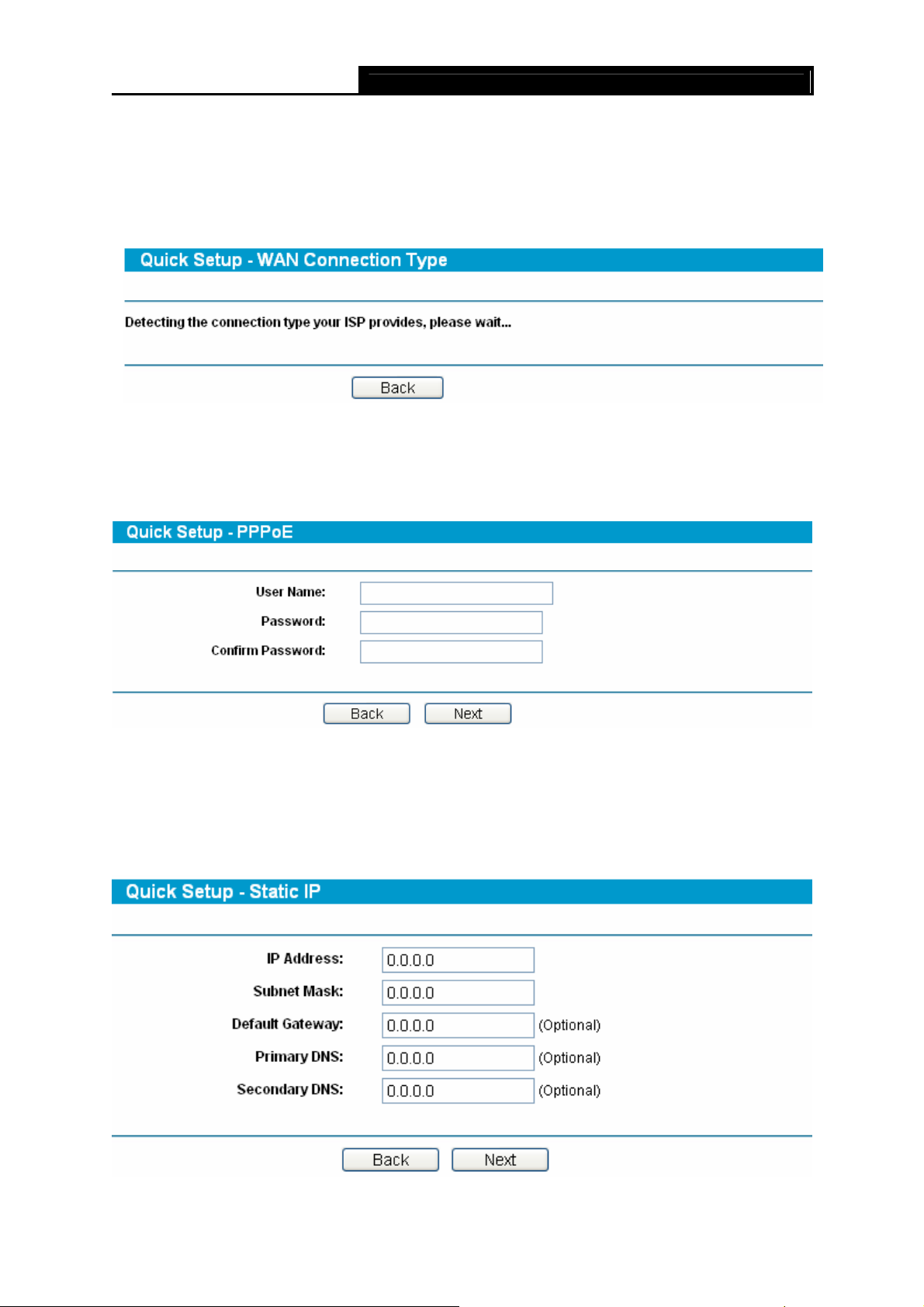
Note:
)
Four ways to connect to Internet are provided in Quick Setup. Please select one compatible with
your ISP. If you are given another way not listed here, refer to Network→ WAN for detailed list.
Step 3: If Auto-Detect is chosen, the router will detect the Internet connection type provided by
your ISP automatically.
Step 4: If you choose PPPoE, you will see the screen as shown in Figure 3-11. Enter the
Username and Password provided by your ISP. These fields are case sensitive. If you
have difficulty with this process, please contact your ISP.
SafeStream Gigabit Broadband VPN Router User GuideTL-R600VPN
Figure 3-10
Figure 3-11
Step 5: If you choose Dynamic IP in Figure 3-9, the router will automatically receive the IP
parameters from your ISP without needing to enter any parameters.
Step 6: If you Choose Static IP, you should enter the detailed IP information in Figure 3-12.
Click the Next button
Figure 3-12
10

SafeStream Gigabit Broadband VPN Router User GuideTL-R600VPN
Step 7: After that, you will see the next screen. Click Finish to complete the quick installation.
Figure 3-13
11

TL-R600VPN SafeStream Gigabit Broadband VPN Router User Guide
Chapter 4. Configuring the Router
It is recommended to use the “Quick Installation Guide” for first-time installation. For advanced
users, if you want to know more about this device and make use of its functions adequately, you
need to read this chapter and configure advanced settings though the Web-based Utility.
After a successful login, you can configure and manage the router. There are main menus on the
left of the Web-based Utility. Submenus will be available after you click one of the main menus.
On the center of the web-based Utility, you can configure the function. Besides this, you can refer
to the help on the right of the Web-based Utility. To apply any settings you have altered on the
page, please click the Save button.
4.1 Status
Choose Status menu, you can view the router’s current status and configuration as shown in
Figure 4-1. All information is read-only.
12
SafeStream Gigabit Broadband VPN Router User GuideTL-R600VPN
Figure 4-1
¾ LAN — This field displays the current information for the LAN, including the “MAC Address”,
“IP Address” and “Subnet Mask”.
¾
WAN —
“MAC Address”, “IP Address”, “Subnet Mask”, “Default Gateway” and so on.
Note:
)
If PPPoE/L2TP/PPTP is chosen as the WAN connection type, the Disconnect button will be
shown here while you are accessing the Internet. You can also cut the connection by clicking the
button. If you have not connected to the Internet, a Connect button will be shown, and you can
then establish the connection by clicking the button.
¾ Traffic Statistics: This field displays the traffic statistics of WAN ports.
¾ System Up Time: This field displays the time of the router running from the time it is powered
on or is reset.
This field displays the parameters applied to the WAN port of the router, including
13

SafeStream Gigabit Broadband VPN Router User GuideTL-R600VPN
4.2 Quick Setup
Please refer to chapter 3″Quick Installation Guide».
4.3 Network
Choose menu Network, the next submenus are shown below.
Figure 4-2
Click any of them, and you will be able to configure the corresponding function. The detailed
explanations for each submenu are provided below.
4.3.1 WAN
Choose menu Network→WAN, you can configure the IP parameters of the WAN on the screen
below.
The router provides six connection types for WAN to connect to the Internet, they are “Dynamic
IP”, “Static IP”, “PPPoE/Russia PPPoE”, ”BigPondCable” , “L2TP/Russia L2TP” and
“PPTP/Russia PPTP”. For configuring the WAN, you should select the connection type firstly
according to your needs.
1. Dynamic IP
If you aren’t given any login parameters and IP information, please select Dynamic IP (shown in
Figure 4-3), then the router will automatically get IP parameters from your ISP. Click the Renew
button to renew the IP parameters from your ISP. Click the Release button to release the IP
parameters.
14
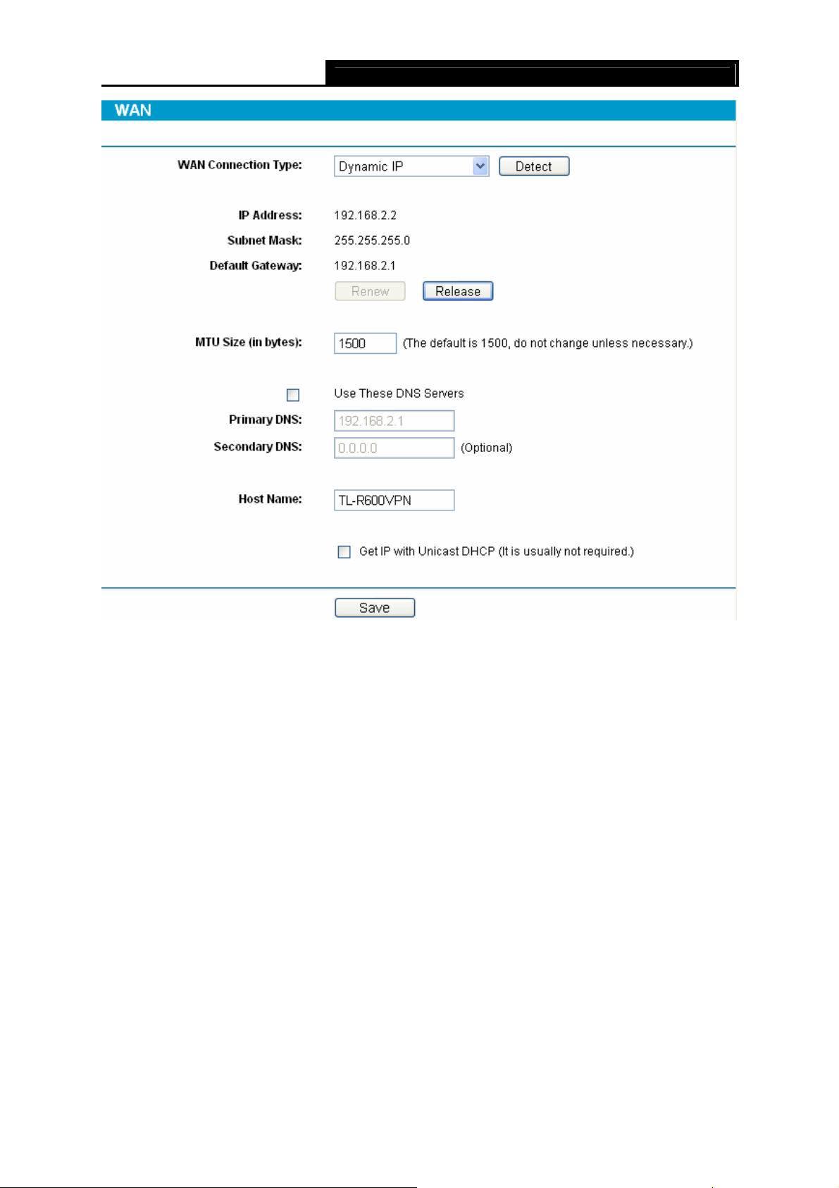
SafeStream Gigabit Broadband VPN Router User GuideTL-R600VPN
Figure 4-3
¾ MTU Size — The normal MTU (Maximum Transmission Unit) value for most Ethernet networks
is 1500 Bytes. For some ISPs you need to reduce the MTU. But this is rarely required, and
should not be done unless you are sure it is necessary for your ISP connection.
¾ Primary DNS & Secondary DNS — If your ISP gives you one or two DNS addresses, select
Use These DNS Servers and enter the primary and secondary addresses into the correct
fields. Otherwise, the DNS servers will be assigned dynamically from ISP.
¾ Host Name – This option specifies the host name of the router.
Note:
)
If you get ‘Address not found’ errors when you go to a Web site, it is likely that your DNS servers
are set up improperly. You should contact your ISP to get correct DNS server.
¾ Get IP with Unicast DHCP: A few ISPs’ DHCP servers do not support the broadcast
applications. If you can not get the IP address normally, you can choose this option. (You
don’t need to select this option generally).
15
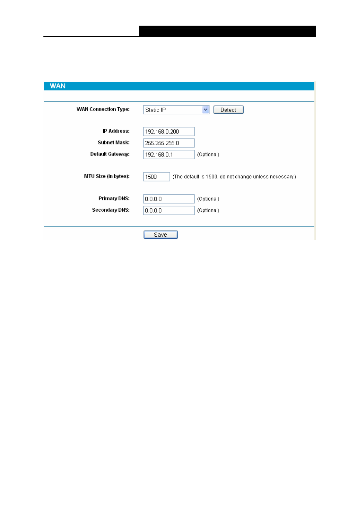
SafeStream Gigabit Broadband VPN Router User GuideTL-R600VPN
2. Static IP
If you are given a fixed IP (static IP), please select Static IP (shown in Figure 4-4), and then fixed
IP parameters specified by your ISP.
Figure 4-4
¾ IP Address — Enter the IP address in dotted-decimal notation provided by your ISP.
¾ Subnet Mask — Enter the subnet Mask in dotted-decimal notation provided by your ISP,
usually is 255.255.255.0.
¾ Default Gateway — Enter the gateway IP address in dotted-decimal notation provided by your
ISP (Optional).
¾ MTU Size — The normal MTU (Maximum Transmission Unit) value for most Ethernet
networks is 1500 Bytes. For some ISPs you may need to modify the MTU. But this is rarely
required, and should not be done unless you are sure it is necessary for your ISP
connection.
¾ Primary DNS — Type the DNS address in dotted-decimal notation provided by your ISP
(Optional).
¾ Secondary DNS — Type another DNS address in dotted-decimal notation provided by your
ISP if provided (Optional).
3. PPPoE/Russia PPPoE
If you are given a user name and a password, please select PPPoE/Russia PPPoE (shown in
Figure 4-5). If you are not sure which connection type you use currently, please contact your ISP
to obtain the correct information.
16
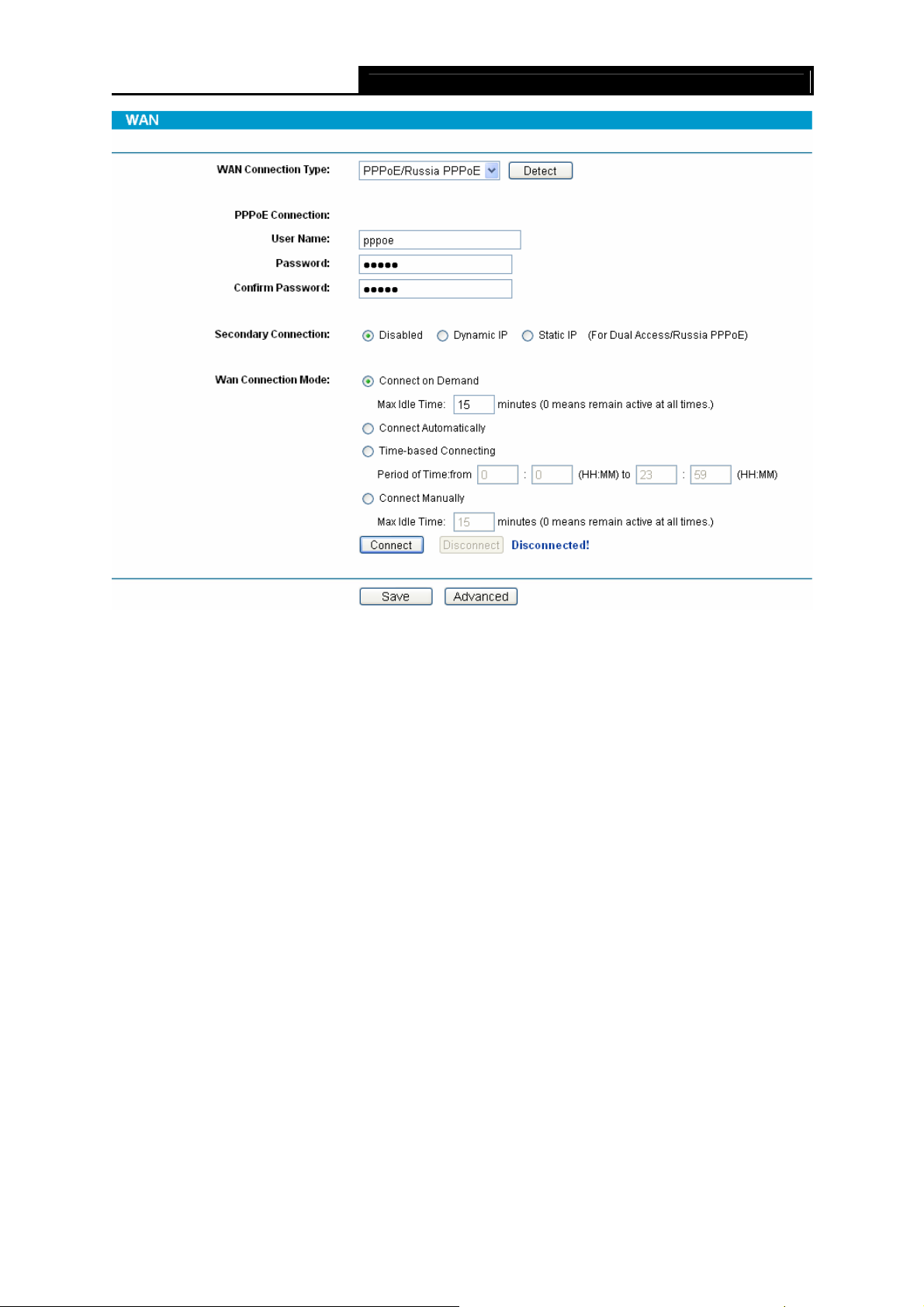
SafeStream Gigabit Broadband VPN Router User GuideTL-R600VPN
Figure 4-5
¾ User Name/Password — Enter the User Name and Password provided by your ISP. These
fields are case-sensitive.
¾ Connect on Demand — You can configure the router to disconnect your Internet connection
after a specified period of inactivity (Max Idle Time). If your Internet connection has been
terminated due to inactivity, Connect on Demand enables the router to automatically
re-establish your connection as soon as you attempt to access the Internet again. If you wish
to activate Connect on Demand, check the radio button and click Save to apply.
Note:
)
1) If you want your Internet connection to remain active at all times, enter 0 in the Max Idle
Time field. Otherwise, enter the number of minutes you want to have elapsed before
your Internet connection terminates.
2) Sometimes the connection can not be disconnected although you specify a time to Max
Idle Time. This is because there may still be active applications in the background, which
may cause fee accounted by your ISP.
¾ Connect Automatically — Connect automatically after the router is disconnected. To use this
option, click the radio button.
¾ Time-based Connecting — You can configure the router to make it connect or disconnect
based on time. Enter the start time in HH:MM for connecting and end time in HH:MM for
disconnecting in the Period of Time fields.
17
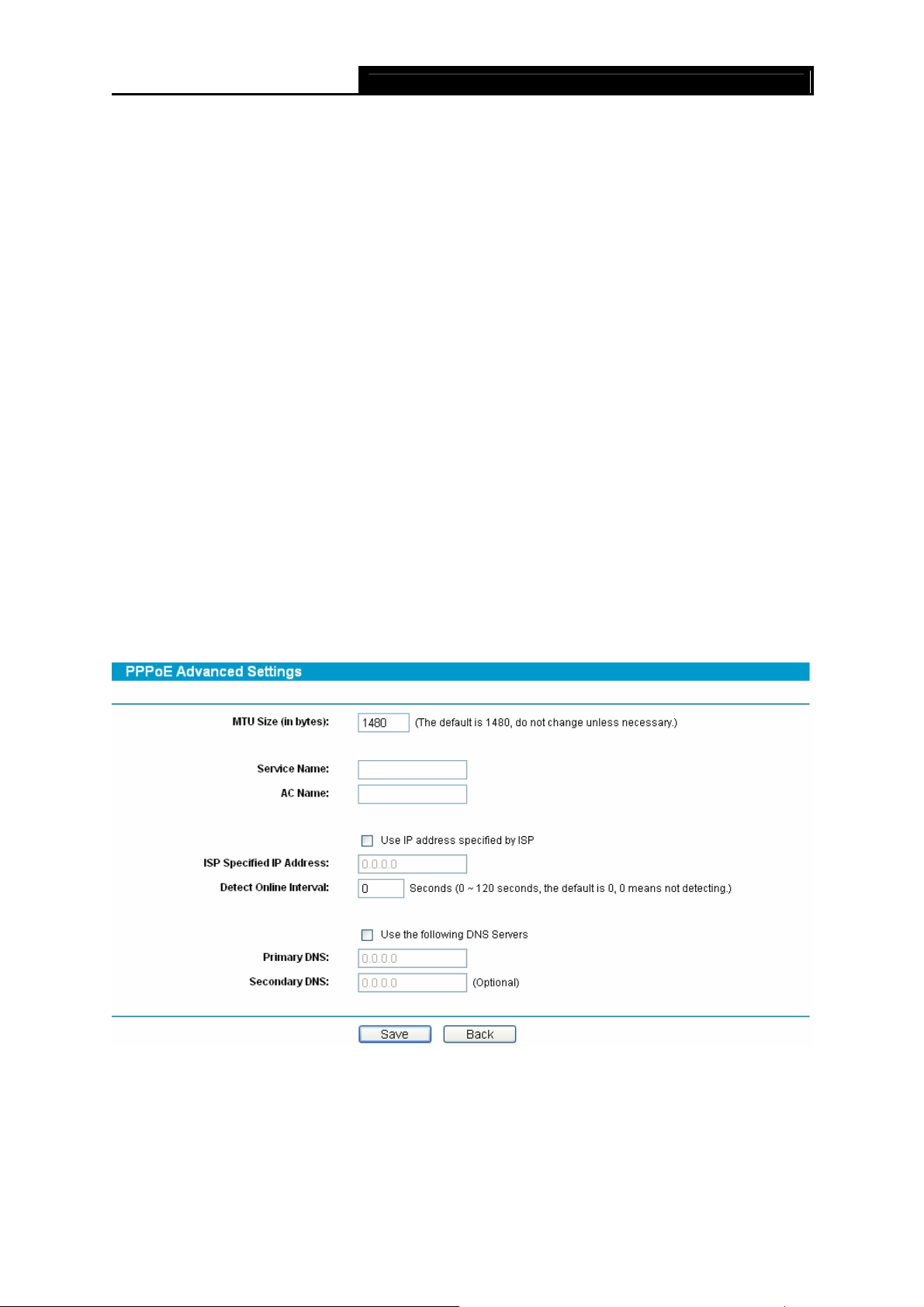
Note:
)
Only you have set the system time on System Tools→Time screen, will the Time-based
Connecting function take effect.
¾ Connect Manually — You can configure the router to make it connect or disconnect manually.
After a specified period of inactivity (Max Idle Time), the router will disconnect your Internet
connection, and not be able to re-establish your connection automatically even though you
attempt to access the Internet again. You need to click the Connect button manually to
connect immediately, or click the Disconnect button manually to disconnect immediately; To
use this option, click the radio button. If you want your Internet connection to remain active at
all times, enter 0 in the Max Idle Time field. Otherwise, enter the number in minutes that you
wish to have the Internet connecting last unless a new link is requested.
Note:
)
1) If you want your Internet connection to remain active at all times, enter 0 in the Max Idle
Time field. Otherwise, enter the number in minutes that you wish to have the Internet
connecting last unless a new link is requested.
SafeStream Gigabit Broadband VPN Router User GuideTL-R600VPN
2) Sometimes the connection cannot be disconnected although you specify a time to Max
Idle Time. This is because there may still be active applications in the background, which
may cause fee accounted by your ISP.
Click the Advanced button to set up the advanced option as shown in Figure 4-6.
Figure 4-6
¾ MTU Size- The default MTU size is 1480 bytes, which is usually fine. For some ISPs, you
need to modify the MTU. This should not be done unless you are sure it is necessary for your
ISP.
¾ Service Name/AC Name — The service name and AC (Access Concentrator) name should
not be configured unless you are sure it is necessary for your ISP.
18
Loading…
Как использовать наш сайт инструкций OnlineManuals.ru
Наша цель состоит в том, чтобы предоставить вам быстрый доступ к содержанию инструкции для устройства wi-fi, роутера TP-LINK TL-R600VPN V1.
С помощью онлайн просмотра, Вы можете быстро просмотреть содержимое инструкции и найти решение проблемы с устройства wi-fi, роутера TP-LINK TL-R600VPN V1.
Для Вашего удобства
Если листать руководство пользователя устройства wi-fi, роутера TP-LINK TL-R600VPN V1 прямо на сайте, не очень удобно для Вас, есть два возможных решения:
• Просмотр в полноэкранном режиме — легко просмотреть руководство пользователя (без загрузки его на свой компьютер), Вы можете использовать режим полноэкранного просмотра.
Для просмотра инструкции пользователя устройства wi-fi, роутера TP-LINK TL-R600VPN V1 на полном экране, используйте кнопку «Открыть в Pdf-viewer».
• Загрузка на компьютер — Вы можете также скачать Руководство пользователя устройства wi-fi, роутера TP-LINK TL-R600VPN V1 на свой компьютер и сохранить его в файлах.
Многие люди предпочитают читать документы не на экране, а в печатной версии.
Возможность печати руководства пользователя также была предусмотрена на нашем сайте,
и вы можете использовать ее, нажав на иконку «печать» в Pdf-viewer.
Нет необходимости печатать все руководство устройства wi-fi, роутера TP-LINK TL-R600VPN V1, можно выбрать только нужные страницы инструкции.
-
Page 1: TP-Link TL-R600VPN
TL-R600VPN SafeStream TM Gigabit Broadband VPN Router Rev: 1.0.0 1910010557[…]
-
Page 2: TP-Link TL-R600VPN
COPYRIGHT & TRADEMARKS Specifications are subjec t to change without notice. is a registered trademark of TP-LINK TECHNOLOGIES CO., LTD. Other br ands and product names are trademarks or registered trademarks of t heir respective holders. No part of the specificat ions may be reproduced in any form or b y any means or used to make any derivativ[…]
-
Page 3: TP-Link TL-R600VPN
FCC STATEMENT This equipment has been tested and found to comply wi th the limits for a Class A digital device, pursuant to part 15 of the FCC Ru les. These limits are designed to pr ovide reasonable protectio n against harmful interference when the equipme nt is operated in a commercial environment. This equipment generates, uses, and can radiate […]
-
Page 4: TP-Link TL-R600VPN
Package Contents The following items should be found in your box: ¾ One TL-R600VPN SafeStream TM Gigabit Broadband VPN Router ¾ One power cord for TL-R600VPN SafeStream TM Gigabit Broadband VPN R outer ¾ One Resource CD for TL-R600VPN SafeStream TM Gigabit Broadba nd VPN Router, including: • This User Guide • Other Helpful Information ) Note[…]
-
Page 5: TP-Link TL-R600VPN
CONTENTS Chapter 1. Introducti on ……………………………………………………………………………. 1 1.1 Overview of the Router …………………………………………………………………………………….. 1 1.2 Features………………………………………………………..[…]
-
Page 6: TP-Link TL-R600VPN
4.7.3 Target …………………………………………………………………………………………………………. …. 40 4.7.4 Schedule ……………………………………………………………………………………………………….. .4 1 4.8 IPsec VPN ……………………………[…]
-
Page 7: TP-Link TL-R600VPN
TL-R600VPN SafeStream TM Gigabit Broadba nd VPN Router U ser Guide 1 Chapter 1. Introduction 1.1 Overview of the Router The TL-R600VPN SafeStream TM Gigabit Broadband VPN Rou ter from TP-LINK provides multiple VPN protocols and high VPN performance. Abundant se curity strategies, such as SPI firewall, protect your network against the attacks and Ac[…]
-
Page 8: TP-Link TL-R600VPN
SafeStream TM Gigabit Broadba nd VPN Router U ser Guide TL-R600VPN Chapter 2. Hardware installation 2.1 Panel Layout 2.1.1 The Front Panel The Router’s LEDs are located on the fr ont panel (Viewed from left to right). Figure 2-1 LED Descriptions: Name Status Indication Not lit The router is powered off. PWR Lit up (Green) The router is powered on[…]
-
Page 9: TP-Link TL-R600VPN
TL-R600VPN SafeStream TM Gigabit Broadba nd VPN Router U ser Guide 3 Method one: Use the Factory Defaults function on Sy stem Tools -> Factory Defaults page in the router’s Web-based Utility. Method two: With the router powered on, use a pin to press and hold the RESET button (about 5 seconds) until the SYS LED lights up and flashes. And th[…]
-
Page 10: TP-Link TL-R600VPN
TL-R600VPN SafeStream Gigab it Broadband VPN Router User Guide TM 4 ) Note: If you intend to connect the Router to the ground via the PE ( Protecting Earth ) cable of AC power cord, please make sure the PE ( Protecting Earth ) cable in the electrical outlet is well grounded in advance. 2.5 Connecting the Router Before you install the router[…]
-
Page 11: TP-Link TL-R600VPN
SafeStream TM Gigabit Broadba nd VPN Router U ser Guide TL-R600VPN 5 2. Conn ect the PC(s) and all Swit ches/Hubs on your LAN to the LAN Ports on the router, shown in Figure 2-3 . 3. Connect the DSL/Cable modem to the WAN port on the router, shown in Figure 2- 3 . 4. Connect the AC power adapter to the AC pow er socket on the router, and the other […]
-
Page 12: TP-Link TL-R600VPN
SafeStream TM Gigabit Broadba nd VPN Router U ser Guide TL-R600VPN Chapter 3. Quick Installation Guide This chapter describes how to c onfigure the basic func tions of your TL-R600VPN SafeStreamTM Gigabit Broadband VPN Router. These procedure s only take you a few minutes. You can access the Internet via the router immediately after it has been suc[…]
-
Page 13: TP-Link TL-R600VPN
TL-R600VPN SafeStream Gigab it Broadband VPN Router User G TM uide 7 Figure 3-2 Step 3: In the next screen, select General tab, highlight Internet Protocol (TCP/IP), and then click the Properties button. Figure 3-3[…]
-
Page 14: TP-Link TL-R600VPN
SafeStream TM Gigabit Broadba nd VPN Router U ser Guide TL-R600VPN 8 Step 4: Configure the IP addr ess as shown in Figure 3-4 . After that, click OK . Figure 3-4 ) Note: You can c onfigure the PC to get an IP addres s automatically, select “ Obt ain an IP address automatically ” and “ Obtain DNS server address automatically ” in the screen […]
-
Page 15: TP-Link TL-R600VPN
SafeStream TM Gigabit Broadba nd VPN Router U ser Guide TL-R600VPN 9 If the result displayed is similar to the screen shown below, it means that your PC has not connected to the Router. Figure 3-6 You can check it follow the steps below: ) Note: 1) Is the connection between your PC and the Router correct? The LEDs of LAN port which you link to the […]
-
Page 16: TP-Link TL-R600VPN
TL-R600VPN SafeStream Gigab it Broadband VPN Ro TM uter User Guide 10 Figure 3-7 ) Note: If the above screen ( Figure 3-7 ) does not prompt, it m eans that your web-browser may be set to a proxy. Choose Tools menu → Internet Options → Connections → LAN Settings , in the screen that appears, cancel the Using Proxy checkbox , and click OK to fi[…]
-
Page 17: TP-Link TL-R600VPN
SafeStream TM Gigabit Broadba nd VPN Router U ser Guide TL-R600VPN 11 ) Note: Four ways to connect to Internet are provided in Quick Setup. Please select one compatible with your ISP. If you are given anothe r way not listed here, refer to Netw ork → WAN for detailed list. Step 3: If Auto-Detect is chosen, the router will detect the Internet co n[…]
-
Page 18: TP-Link TL-R600VPN
SafeStream TM Gigabit Broadba nd VPN Router U ser Guide TL-R600VPN 12 Step 7: After that, you will see the next screen. Click Finish to complete the quick installation. Figure 3-13[…]
-
Page 19: TP-Link TL-R600VPN
TL-R600VPN SafeStream TM Gigabit Broadba nd VPN Router U ser Guide 13 Chapter 4. Configuring the Router It is recommended to use the “Quick Installation Gu ide” for first-time installation. For advanced users, if you want to know mo re about this device and make use of its functions adequately, you need to read this chapter and configure advanc[…]
-
Page 20: TP-Link TL-R600VPN
TL-R600VPN SafeStream Gigab it Broadband VPN Router User Guide TM 14 Figure 4-1 ¾ LAN — This field displays the current informat ion for the LAN, i ncluding the “MAC address”, “IP address” and “Subnet Mask”. ¾ WAN — This field displays the parameters applied to the WAN port of the router, including “MAC address”, “IP address”,[…]
-
Page 21: TP-Link TL-R600VPN
SafeStream TM Gigabit Broadba nd VPN Router U ser Guide TL-R600VPN 15 4.2 Quick Setup Please refer to chapter 3″Quick Installation Guide» . 4.3 Network Choose menu “ Network ”, the next submenus are shown below. Figure 4-2 Click any of them, and you will be able to c onfigure the corresponding function. The detailed explanations for e[…]
-
Page 22: TP-Link TL-R600VPN
TL-R600VPN SafeStream Gigab it Broadband VPN Router User Guide TM 16 Figure 4-3 ¾ MTU Size — The normal MTU (Maximum Transmission Unit) value for most Ethernet networks is 1500 Bytes. For some ISPs you need to reduce the MTU. But this is rarely required, and should not be done unless you are sure it is necessary for yo ur ISP connection. ¾ Primar[…]
-
Page 23: TP-Link TL-R600VPN
SafeStream TM Gigabit Broadba nd VPN Router U ser Guide TL-R600VPN 17 2. Static IP If you are given a fixed IP (static IP), please select Static IP (shown in Figure 4-4 ), and then fixed IP parameters specified by your ISP. Figure 4-4 ¾ IP Address — Enter the IP address in dotted-decim al notation provided by your ISP. ¾ Subnet Mask — Enter the s[…]
-
Page 24: TP-Link TL-R600VPN
TL-R600VPN SafeStream Gigab it Broadband VPN Router User Guide TM 18 Figure 4-5 ¾ User Name/Passw ord — Enter the User Name and Password provided by your ISP. These fields are case-sensitive. ¾ Connect on Demand — You can configure the router to disconnect your Internet connection after a specified period of inactivity ( Max Idle Time ). If your […]
-
Page 25: TP-Link TL-R600VPN
SafeStream TM Gigabit Broadba nd VPN Router U ser Guide TL-R600VPN 19 ) Note: Only you have set the system time on System Tools → Tim e screen, will the Time-based Connecting function take effect. ¾ Connect Manually — You can configure the router to make it connect or disconnect manually. After a specified peri od of inactivity ( Max Idle Time )[…]
-
Page 26: TP-Link TL-R600VPN
SafeStream TM Gigabit Broadba nd VPN Router U ser Guide TL-R600VPN 20 ¾ ISP Specified IP Address — If you know that your ISP does not automatically transmit your IP address to the router during login, select Use IP Address specified by ISP and enter the IP address in dotted-decimal notation, which your ISP provided. ¾ Detect Online Interval — The[…]
-
Page 27: TP-Link TL-R600VPN
TL-R600VPN SafeStream TM Gigabit Broadba nd VPN Router U ser Guide 21 ¾ Connect on Demand — You can configure the router to disconnect your Internet connection after a specified period of the Internet connectivity ( Max Idle Time ). If your Internet connection has been terminat ed due to inactivity, Connect on Demand enables the router to automati[…]
-
Page 28: TP-Link TL-R600VPN
TL-R600VPN SafeStream Gigab it Broadband VPN Router User Guide TM 22 Figure 4-8 ¾ User Name/Password — Enter the User Name and Password provided by your ISP. Thes e fields are case-sensitive. ¾ Connect on Demand — You can configure the router to disconnect your Internet connection after a specified period of the Internet connectivity ( Max Idle T[…]
-
Page 29: TP-Link TL-R600VPN
SafeStream TM Gigabit Broadba nd VPN Router U ser Guide TL-R600VPN 23 Otherwise, enter the number in minutes that you wish to hav e the Internet connecting last unless a new link requested. ) Note: Sometimes the connection cannot be disconnec ted although you spec ify a time to Max Idle Time because some applications visit the Inte rnet continually[…]
-
Page 30: TP-Link TL-R600VPN
SafeStream TM Gigabit Broadba nd VPN Router U ser Guide TL-R600VPN 24 enter the number of minutes you want to have elapsed before your Internet connection terminates. ¾ Connect Automatically — Connect automatically after the r outer is disconnect ed. To use this option, click the radio button. ¾ Connect Manually — You can configure the router to […]
-
Page 31: TP-Link TL-R600VPN
SafeStream TM Gigabit Broadba nd VPN Router U ser Guide TL-R600VPN 25 Server and DMZ Host may change accordingly at the same time; you’d better re-configure it as well. 4.3.3 MAC Clone Choose menu “ Netw ork → MAC Clone ”, you can configure the MA C address of the WAN on the screen below (shown in Figure 4-11 ). Some ISPs require that you r[…]
-
Page 32: TP-Link TL-R600VPN
SafeStream TM Gigabit Broadba nd VPN Router U ser Guide TL-R600VPN 26 4.4 DHCP Choose menu “ DHCP ”, the next submenus are shown below. Figure 4-12 Click any of them, and you will be able to c onfigure the corresponding function. The detailed explanations for each submenu are provide d below. 4.4.1 DHCP Settings Choose menu “ DHCP → DHCP Se[…]
-
Page 33: TP-Link TL-R600VPN
SafeStream TM Gigabit Broadba nd VPN Router U ser Guide TL-R600VPN 27 ¾ Address Lease Time — This is the amount of time in which a network user will be allowed connection to the router with t heir current dynamic IP address. Enter the amount of time (in minutes), the range of the time is 1 ~ 2 880 minutes. The default value is 120 minutes. ¾ Defa[…]
-
Page 34: TP-Link TL-R600VPN
TL-R600VPN SafeStream Gigab it Broadband VPN Router User Guide TM 28 Figure 4-15 ¾ MAC Address — This field displays the MAC address of the PC for which you want to reserve IP address. ¾ Assigned IP Address — This field displays the IP ad dress of the router reserved. ¾ Status — This field displays the status of the virtual server entry. Enabled[…]
-
Page 35: TP-Link TL-R600VPN
SafeStream TM Gigabit Broadba nd VPN Router U ser Guide TL-R600VPN 29 Click the Previous button to view the information in the previous screen, click the Next but ton to view the information in the next screen. 4.5 Forwarding Choose menu “ Forwarding ”, the next submenus are shown below. Figure 4-17 Click any of them, and you will be able to c […]
-
Page 36: TP-Link TL-R600VPN
SafeStream TM Gigabit Broadba nd VPN Router U ser Guide TL-R600VPN 30 To add/modify a virtual server entry: Step 1: Click Add New… / Modify shown in Figure 4-18 , you will see a new screen shown in Figure 4-19 . Step 2: Select the service you want from the “ Common Service Port ”, then the port and protocol value will be added to the corres p[…]
-
Page 37: TP-Link TL-R600VPN
SafeStream TM Gigabit Broadba nd VPN Router U ser Guide TL-R600VPN 31 4.5.2 Port Triggering Choose menu “ Forwarding → Port Triggering ”, you can view and add port triggeri ng in the next screen (shown in Figure 4-20 ). Some applications require multiple connections, like Internet game s, video conferencing, Internet calling and so on. These […]
-
Page 38: TP-Link TL-R600VPN
SafeStream TM Gigabit Broadba nd VPN Router U ser Guide TL-R600VPN 32 To add/modify a port triggering entry: Step 1: Click Add New… / Modify shown in Figure 4-20 , you will see a new screen shown in Figure 4-21 . Step 2: Select the application you want from the “ Common Applications ”, then the Trigger port and Incoming ports will be added to[…]
-
Page 39: TP-Link TL-R600VPN
SafeStream TM Gigabit Broadba nd VPN Router U ser Guide TL-R600VPN 33 4.5.3 DMZ Choose menu “ Forwarding → DMZ ”, you can vi ew and configure DMZ host in the screen (shown in Figure 4-22 ). The DMZ host feature allows one local host to be exposed to the Internet for a special-purp ose service such as Internet gaming or videoconferen cing. DMZ[…]
-
Page 40: TP-Link TL-R600VPN
TL-R600VPN SafeStream Gigab it Broadband VPN Router User Guide TM 34 Figure 4-23 ¾ Current UPnP Status — If you want to use the Router’s UPnP f unction, please click Enable button. If you don’t want use the function, please click Disable button. Allowing the function may cause a risk to security; this featu re is disabled by default. ¾ App De[…]
-
Page 41: TP-Link TL-R600VPN
TL-R600VPN SafeStream Gigab it Broadband VPN Router User Guide TM 35 Figure 4-25 ¾ Firewall — Enable the general firewall or not. • SPI Fire wall — SPI (Stateful Packet Inspection) k eeps track of the state of network connections traveling across it. It distinguishes legitimate pac kets for different types of connections. Only packets matc hing […]
-
Page 42: TP-Link TL-R600VPN
SafeStream TM Gigabit Broadba nd VPN Router U ser Guide TL-R600VPN 36 4.6.2 Advanced Security Choose menu “ Security → Advanced Security ”, you can protect the Router from being attacked by TCP-SYN Flood, UDP Flood and ICMP-Flood in the next screen (shown in Figure 4-26 ). Figure 4-26 ¾ Packets Statistics Interval — This is the interval for […]
-
Page 43: TP-Link TL-R600VPN
SafeStream TM Gigabit Broadba nd VPN Router U ser Guide TL-R600VPN 37 4.6.3 Local Management Choose menu “ Security → Local Management ”, you can configure to pr event the local PCs from accessing the router’s web-based ut ility in the next screen (shown in Figure 4-27 ). Figure 4-27 ¾ Management Rules — Here displays the management rules […]
-
Page 44: TP-Link TL-R600VPN
SafeStream TM Gigabit Broadba nd VPN Router U ser Guide TL-R600VPN 38 4.7.1 Rule Choose menu “ Access Control → Rule ”, you can configure the In ternet Access Control to manage Internet activities from LA N hosts in the next screen (shown in Figure 4-29 ). Figure 4-29 ¾ Enable Internet Access Control: Enable or disable the Internet Access Co[…]
-
Page 45: TP-Link TL-R600VPN
TL-R600VPN SafeStream Gigab it Broadband VPN Router User Guide TM 39 Figure 4-30 Step 3: Click the Save button. Other configurations for the entries as shown in Figure 4-29 : Click the Delete button to delete the entry. Click the Enable All button to enable all the entries. Click the Disable All button to disable all the entries. Click the Delete A[…]
-
Page 46: TP-Link TL-R600VPN
SafeStream TM Gigabit Broadba nd VPN Router U ser Guide TL-R600VPN 40 Step 2: Select the Mode and enter the Host Description and LAN IP Address. Figure 4-32 Step 3: Click the Save button. Other configurations for the entries as shown in Figure 4-31 : Click the Delete All button to delete all the entries. Click the Previous button to view the inform[…]
-
Page 47: TP-Link TL-R600VPN
TL-R600VPN SafeStream Gigab it Broadband VPN Router User Guide TM 41 Figure 4-34 Step 3: Click the Save button. Other configurations for the entries as shown in Figure 4-33 : Click the Delete All button to delete all the entries. Click the Previous button to view the information in the previous screen, click the Next button to view the information […]
-
Page 48: TP-Link TL-R600VPN
SafeStream TM Gigabit Broadba nd VPN Router U ser Guide TL-R600VPN 42 To add/modify a target for Access Control Rule: Step 1: Click Add New… / Edit shown in Figure 4-35 , you will see a new screen shown in Figure 4-36 . Step 2: Enter the Schedule Description and select the days, and then specify the Start Time and Stop Time. Figure 4-36 Step 3: C[…]
-
Page 49: TP-Link TL-R600VPN
TL-R600VPN SafeStream Gigab it Broadband VPN Router User Guide TM 43 Figure 4-38 ¾ Policy Name: The unique name to the IKE policy for identification and management purposes. ¾ Exchange Mode: Displays the IKE Exchange Mode in phase 1, and the remote VPN peer uses the same mode. z Main: Main mode provides identity prot ection and exchange s more in[…]
-
Page 50: TP-Link TL-R600VPN
SafeStream TM Gigabit Broadba nd VPN Router U ser Guide TL-R600VPN 44 z DH3: 1536 bits ¾ Pre-shared Key: The Pre-shared Key for IKE authentic ation, and e nsure both the two peers use the same key. The key s hould consist of visible charac ters without blank space. To add/modify an IKE entry: Step 1: Click Add New…/Modify shown in Figure 4-38 , […]
-
Page 51: TP-Link TL-R600VPN
TL-R600VPN SafeStream Gigab it Broadband VPN Router User Guide TM 45 Figure 4-40 ¾ IPSec: Enable or disable IPsec and click save to apply. ¾ Policy Name: The unique name to the IPsec polic y for identification and management purposes. ¾ Local Subnet: The IP address range on your local LAN to identify which PCs on your LAN are covered by this pol[…]
-
Page 52: TP-Link TL-R600VPN
TL-R600VPN SafeStream Gigab it Broadband VPN Router User Guide TM 46 Figure 4-41 ¾ Policy Name: Enter the unique name to the IPsec po licy for identificat ion and management purposes. ¾ Local Subnet: Enter the IP address range on your local LAN to identify which PCs on your LAN are covered by this policy. It’ s formed by IP address and subne[…]
-
Page 53: TP-Link TL-R600VPN
TL-R600VPN SafeStream TM Gigabit Broadba nd VPN Router U ser Guide 47 Encryption Algorithm: Select the Encryption Algorithm for IPsec policy . The default value is “Auto”. IKE Security Policy: Select the IK E Security Policy for IPsec policy . PFS Group: Select the PFS (Perfect Forward Security) for IKE mode to enhance security . This setting s[…]
-
Page 54: TP-Link TL-R600VPN
TL-R600VPN SafeStream TM Gigabit Broadba nd VPN Router U ser Guide 48 authentication key at the other end of the tunnel, and vice versa. In Encryption Key: S pecify the Inbound Encryption Key manually if ESP protocol The inbound key here must match the outbound Encryption Key at the other end of the tunnel, and vice versa. Outgoing SPI: S pecify th[…]
-
Page 55: TP-Link TL-R600VPN
TL-R600VPN SafeStream Gigab it Broadband VPN Router User Guide TM 49 Figure 4-42 This page displays the connection st atus of the IPsec Policy . As Se curity Association is unidirec- tional, an ingoing SA and an outgoing SA are created to protect data flows for each tunnel after IPsec tunnel is successfully established. The ingoing SPI va lue and o[…]
-
Page 56: TP-Link TL-R600VPN
SafeStream TM Gigabit Broadba nd VPN Router U ser Guide TL-R600VPN 50 ¾ MPPE Encryption – Enable or disable the MPPE Encr yption. If enabled, the PPTP tunnel will be encrypted by MPPE. ¾ IP Range Start — Enter the start IP address to define a range for the server’s IP assignment. ¾ IP Range End — Enter the end IP address to define a range[…]
-
Page 57: TP-Link TL-R600VPN
SafeStream TM Gigabit Broadba nd VPN Router U ser Guide TL-R600VPN 51 Click the Previous button to view the information in the previous screen, click the Next button to view the information in the next screen. 4.9.3 Connection Status Choose the menu PPTP VPN Server → Connection St atus , you can view t he connection status of each user in the nex[…]
-
Page 58: TP-Link TL-R600VPN
SafeStream TM Gigabit Broadba nd VPN Router U ser Guide TL-R600VPN 52 To add/modify a static routing entry : Step 1: Click Add New… / Modify shown in Figure 4-48 , you will see a new screen shown in Figure 4-49 . Step 2: Enter the appropriate Desti nation IP Address, Subnet Mask and Default Gateway, and then select the status. Figure 4-49 Step 3:[…]
-
Page 59: TP-Link TL-R600VPN
TL-R600VPN SafeStream Gigab it Broadband VPN Router User Guide TM 53 Figure 4-51 ¾ Enable Bandwidth Control — Enable or disable t he Bandwidth Control. ¾ Line Type — Select the Line Type of the WAN port. ¾ Egress/Ingress Bandwidth – Enter the Egress and Ingress Bandwidth through the WAN port. 4.11.2 Rule List Figure 4-52 ¾ Description — This […]
-
Page 60: TP-Link TL-R600VPN
TL-R600VPN SafeStream Gigab it Broadband VPN Router User Guide TM 54 Figure 4-53 Step 3: Click the Save button. Other configurations for the entries as shown in Figure 4-52 : Click the Delete All button to delete all the entries. Click the Previous button to view the information in the previous screen, click the Next button to view the information […]
-
Page 61: TP-Link TL-R600VPN
SafeStream TM Gigabit Broadba nd VPN Router U ser Guide TL-R600VPN 55 ¾ MAC Address — This field displays the MAC address of the controlled computer in the LAN. ¾ IP Address — This field displays the assigned IP addr ess of the controlled computer in the LAN. ¾ Bind — Select whether enable the ARP binding or not. Only bi nd the MAC address and I[…]
-
Page 62: TP-Link TL-R600VPN
TL-R600VPN SafeStream Gigab it Broadband VPN Router User Guide TM 56 Step 4: Click Back to return the previous screen. ) Note: You can click “to page” to edit the entry in the corresponding screen. Other configurations for the entries as shown in Figure 4-55 : Click the Delete button to delete the entry. Click the Enable All button to enable al[…]
-
Page 63: TP-Link TL-R600VPN
SafeStream TM Gigabit Broadba nd VPN Router U ser Guide TL-R600VPN 57 Click Delete to load the specific item to the IP & MAC Binding list. Click the Bind All button to bind all the current items, available after enable. Click the Load All button to load all items to the IP & MAC Bind ing list (shown in Figure 4-55 ). Click the Refresh butto[…]
-
Page 64: TP-Link TL-R600VPN
SafeStream TM Gigabit Broadba nd VPN Router U ser Guide TL-R600VPN 58 Click Logout to logout the DDNS service. The status of the DDNS service connection is displayed in the Connection Status field. 4.13.2 PeanutHull DDNS If your dynamic DNS Service Provider is www .oray .net , you can configure in the next screen (shown in Figure 4-60 ). Figure 4-6[…]
-
Page 65: TP-Link TL-R600VPN
TL-R600VPN SafeStream Gigab it Broadband VPN Router User Guide TM 59 Figure 4-61 To set up for Comexe DDNS, follow these instructions: Step 1: Enter the domain name your dynamic DNS service provider offer. Step 2: Type the “Us er Name” and “Password” for your DD NS account. Step 3: Enable DDNS, and click Save to save the current configurati[…]
-
Page 66: TP-Link TL-R600VPN
TL-R600VPN SafeStream Gigab it Broadband VPN Router User Guide TM 60 Figure 4-62 To set up for No-IP DDNS, follow these instructions: Step 1 Type the “ User Name ” and “ Password ” for your DDNS account. Step 2 Enter the Domain Name your dynamic DNS service provider offered. Step 3 Enable DDNS, and click Save to save the current configurati[…]
-
Page 67: TP-Link TL-R600VPN
SafeStream TM Gigabit Broadba nd VPN Router U ser Guide TL-R600VPN 61 4.14.1 Time Settings Choose menu “ System Tools → Time Settings ”, you can configure t he time on the screen (shown in Figure 4-64 ). Figure 4-64 ¾ Time zone — Select your local time z one from this pull down list. ¾ Date — Enter your local date in MM/DD/YY into the right[…]
-
Page 68: TP-Link TL-R600VPN
SafeStream TM Gigabit Broadba nd VPN Router U ser Guide TL-R600VPN 62 4.14.2 Diagnostic Tools Choose menu “ System Tools → Diagnostic Tools ”, you can test the connectivity between the router and the destination on this page. Figure 4-65 ¾ Diagnostic Tool — Choose the diagnostic tool. Ping and Tracert are available. ¾ IP address/Domain Name[…]
-
Page 69: TP-Link TL-R600VPN
SafeStream TM Gigabit Broadba nd VPN Router U ser Guide TL-R600VPN 63 Figure 4-66 ¾ Firmware Version — This displays the current firmware version. ¾ Hardware Version — This displays the current hardware version. The hardw are version of the upgrade file must accord with the R outer’s current hardware version. To upgrade the router’s firmwa[…]
-
Page 70: TP-Link TL-R600VPN
SafeStream TM Gigabit Broadba nd VPN Router U ser Guide TL-R600VPN 64 ) Note: 1) The default User Name is admin. 2) The default Password is admin. 3) The default IP Address is 192.168.0.1. 4) The default Subnet Mask is 255.255.255.0. All settings you have saved will be lost when the default settings are restored. 4.14.5 Backup and Restore Choose me[…]
-
Page 71: TP-Link TL-R600VPN
TL-R600VPN SafeStream Gigab it Broadband VPN Router User Guide TM 65 Figure 4-70 To restore the Router’s settings: Step 1: Click the Browse button to locate the update file for the device , or enter the exact path to the Setting file in the text box. Step 2: Click the Restore button to complete. 4.14.6 Reboot Choose menu “ System Tools → Rebo[…]
-
Page 72: TP-Link TL-R600VPN
SafeStream TM Gigabit Broadba nd VPN Router U ser Guide TL-R600VPN 66 6) Upgrade the firmware of the router (system will reboot automatically). 7) Restore the router’s settings to factory default (system will reboot automatically). 4.14.7 Password Choose menu “ System Tools → Passw ord ”, you can change the factor y d efault user name an[…]
-
Page 73: TP-Link TL-R600VPN
TL-R600VPN SafeStream Gigab it Broadband VPN Router User Guide TM 67 Figure 4-73 The router can keep logs of all traffic. You c an query the logs to find what happened to the router. Click the Refresh button to refresh the logs. Click the Save Log button to save all the logs in a text file. Click the Mail Log button to send the logs to the specifie[…]
-
Page 74: TP-Link TL-R600VPN
SafeStream TM Gigabit Broadba nd VPN Router U ser Guide TL-R600VPN 68 ¾ Remote Management IP Address — This is the current address you will use when accessing your router from the Internet. The default IP addr ess is 0.0.0.0. It means this function is disabled. To enable this function, change the defau lt IP address to another IP address as desire[…]
-
Page 75: TP-Link TL-R600VPN
TL-R600VPN SafeStream TM Gigabit Broadba nd VPN Router U ser Guide 69 IP Address MAC Address The IP address whose statistics information are displayed Packets The total amount of packets received and transmitted by the router Total Byt es The total amount of bytes receiv ed and transmitted by the r outer Packets The total amount of packets received[…]
-
Page 76: TP-Link TL-R600VPN
TL-R600VPN SafeStream TM Gigabit Broadba nd VPN Router U ser Guide 70 Appendix A: Specifications General Standards and Protocols IEEE 802.3 、 IEEE 802.3u 、 IEEE 802.3ab 、 TCP/ IP 、 DHCP 、 ICMP 、 NAT 、 PPPoE 、 SNTP 、 HTTP 、 DNS Safety & Emission FCC 、 CE Ports One 10/100/1000Mbps Auto-Negotiation WAN RJ45 port Four 10/100/1[…]
-
Page 77: TP-Link TL-R600VPN
TL-R600VPN SafeStream TM Gigabit Broadba nd VPN Router U ser Guide 71 Appendix B: Preventing Lightning To avoid damage during a lightning storm and ensu re a stable performance, our router has adopted the professional lightning protection technology to prev ent the lightning. However, although these measures have bee n taken to protect TL-R600VPN f[…]
-
Page 78: TP-Link TL-R600VPN
SafeStream TM Gigabit Broadba nd VPN Router U ser Guide TL-R600VPN 72 Appendix C: FAQ 1. How do I configure the router to access Internet by ADSL users? Step 1: First, configure the ADSL m odem in RFC1483 bridge model. Step 2: Connect the Ethernet cable from your ADSL modem to the WAN port on the router. The telephone cord plugs into the Line port […]
-
Page 79: TP-Link TL-R600VPN
SafeStream TM Gigabit Broadba nd VPN Router U ser Guide TL-R600VPN 73 2. How do I configure the router to access Internet by Ethernet users? Step 1: Login to the router, click the menu Network → WAN on the left of your browser, On the WAN screen, select “ Dynamic IP ” for » WAN Connection T ype «, and finish it by clicking Save . St[…]
-
Page 80: TP-Link TL-R600VPN
TL-R600VPN SafeStream Gigab it Broadband VPN Router User Guide TM 74 Figure 4 ) Note: Your opposite side should call your WAN IP, which is displayed on the “Status” page. Method two: Use DMZ Host Login to the router, click the menu Forwarding → DMZ . On the DMZ screen, select “Enable”, and enter your IP address into the “DMZ Host IP Add[…]
-
Page 81: TP-Link TL-R600VPN
TL-R600VPN SafeStream Gigab it Broadband VPN Router User Gu TM ide 75 Figure 6 ) Note: If the above configuration takes effect, you should login the Router by entering http://192.168.0.1:88 (the router’s LAN IP address: Web Mana gement Port) in the addres s field of the web browser. Step 2: To add a WEB Server: Login to the router, click the menu[…]
-
Page 82: TP-Link TL-R600VPN
TL-R600VPN SafeStream TM Gigabit Broadba nd VPN Router U ser Guide 76 Appendix D: Glossary ¾ DDNS ( D ynamic D omain N ame S ystem) — The capability of assigning a fixed host and domain name to a dynamic Internet IP address. ¾ DHCP ( D ynamic H ost C onfiguration P rotocol) — A protocol that autom atically configure the TCP/IP parameters for the […]
Устройство:
TP-Link TL-R600VPN
Размер: 1.34 MB
Добавлено: 10/14/2013
Количество страниц: 82
Как пользоваться?
Наша цель — обеспечить Вам самый быстрый доступ к руководству по эксплуатации устройства TP-Link TL-R600VPN. Пользуясь просмотром онлайн Вы можете быстро просмотреть содержание и перейти на страницу, на которой найдете решение своей проблемы с TP-Link TL-R600VPN.
Для Вашего удобства
Если просмотр руководства TP-Link TL-R600VPN непосредственно на этой странице для Вас неудобен, Вы можете воспользоваться двумя возможными решениями:
- Полноэкранный просмотр -, Чтобы удобно просматривать инструкцию (без скачивания на компьютер) Вы можете использовать режим полноэкранного просмотра. Чтобы запустить просмотр инструкции TP-Link TL-R600VPN на полном экране, используйте кнопку Полный экран.
- Скачивание на компьютер — Вы можете также скачать инструкцию TP-Link TL-R600VPN на свой компьютер и сохранить ее в своем архиве. Если ты все же не хотите занимать место на своем устройстве, Вы всегда можете скачать ее из ManualsBase.
TP-Link TL-R600VPN Руководство по эксплуатации — Online PDF
Печатная версия
Многие предпочитают читать документы не на экране, а в печатной версии. Опция распечатки инструкции также предусмотрена и Вы можете воспользоваться ею нажав на ссылку, находящуюся выше — Печатать инструкцию. Вам не обязательно печатать всю инструкцию TP-Link TL-R600VPN а только некоторые страницы. Берегите бумагу.
Резюме
Ниже Вы найдете заявки которые находятся на очередных страницах инструкции для TP-Link TL-R600VPN. Если Вы хотите быстро просмотреть содержимое страниц, которые находятся на очередных страницах инструкции, Вы воспользоваться ими.