
|
Код: 159303
Бесплатная доставка ? В корзину Сравнить Купить в один клик Новости интернет-магазина «Лаукар»:23.04.2025 26.02.2025 17.02.2025 Дополнительная информация в категории Тепловизор:Таблица Авторизованных сервисных центров по брендам. Описание Инструкция Отзывы (0) В интернет-магазине бытовой техники «Лаукар» Вы можете скачать инструкцию к товару Тепловизор Bosch GTC 400 C [0601083101] совершенно бесплатно. Все инструкции, представленные на сайте интернет-магазина бытовой техники «Лаукар», предоставляются производителем товара. Для того чтобы скачать инструкцию, Вам необходимо нажать на ссылку «скачать инструкцию», расположенную ниже, а в случае, если ссылки нет, Скачать инструкцию Смотреть инструкцию 
Фирма-производитель оставляет за собой право на внесение изменений в конструкцию, дизайн и комплектацию товара: Тепловизор Bosch GTC 400 C [0601083101]. Пожалуйста, сверяйте информацию о товаре с информацией на |
OBJ_BUCH-3136-002.book Page 1 Tuesday, August 22, 2017 6:25 PM
Robert Bosch Power Tools GmbH
70538 Stuttgart
GERMANY
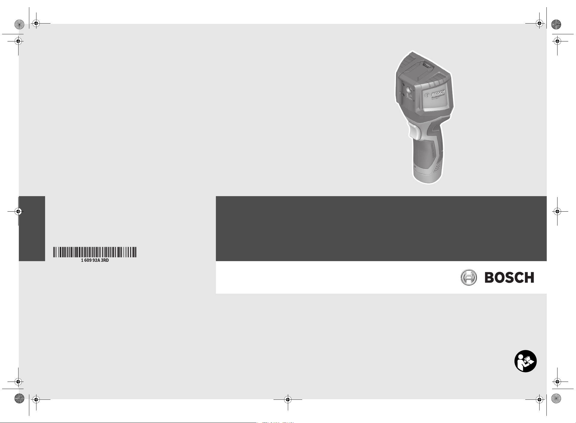
GTC 400 C Professional
www.bosch-pt.com
1 609 92A 3RD (2017.08) T / 322
de Originalbetriebsanleitung
en Original instructions
fr Notice originale
es Manual original
pt Manual original
it Istruzioni originali
nl Oorspronkelijke gebruiksaanwijzing
da Original brugsanvisning
sv Bruksanvisning i original
no Original driftsinstruks
fi Alkuperäiset ohjeet
el Πρωτότυπο οδηγιών χρήσης
tr Orijinal işletme talimatı
pl Instrukcja oryginalna
cs Původní návod k používání
sk Pôvodný návod na použitie
hu Eredeti használati utasítás
ru Оригинальное руководство
по эксплуатации
uk Оригінальна інструкція з
експлуатації
kk Пайдалану нұсқаулығының
түпнұсқасы
ro Instrucţiuni originale
bg Оригинална инструкция
mk Оригинално упатство за работа
sr Originalno uputstvo za rad
sl Izvirna navodila
hr Originalne upute za rad
et Algupärane kasutusjuhend
lv Instrukcijas oriģinālvalodā
lt Originali instrukcija
ko 사용 설명서 원본
ar
fa
OBJ_BUCH-3136-002.book Page 2 Tuesday, August 22, 2017 6:26 PM
2 |
Deutsch. . . . . . . . . . . . . . . . . . . . . . . . . . . . . . . . . . . . . . . . . Seite 6
English . . . . . . . . . . . . . . . . . . . . . . . . . . . . . . . . . . . . . . . . . . Page 16
Français . . . . . . . . . . . . . . . . . . . . . . . . . . . . . . . . . . . . . . . . . Page 26
Español . . . . . . . . . . . . . . . . . . . . . . . . . . . . . . . . . . . . . . . . Página 36
Português . . . . . . . . . . . . . . . . . . . . . . . . . . . . . . . . . . . . . . Página 47
Italiano . . . . . . . . . . . . . . . . . . . . . . . . . . . . . . . . . . . . . . . . Pagina 57
Nederlands . . . . . . . . . . . . . . . . . . . . . . . . . . . . . . . . . . . . . Pagina 67
Dansk . . . . . . . . . . . . . . . . . . . . . . . . . . . . . . . . . . . . . . . . . . . Side 77
Svenska . . . . . . . . . . . . . . . . . . . . . . . . . . . . . . . . . . . . . . . . . Sida 86
Norsk. . . . . . . . . . . . . . . . . . . . . . . . . . . . . . . . . . . . . . . . . . . . Side 95
Suomi . . . . . . . . . . . . . . . . . . . . . . . . . . . . . . . . . . . . . . . . . . . Sivu 104
Ελληνικά . . . . . . . . . . . . . . . . . . . . . . . . . . . . . . . . . . . . . . . Σελίδα 113
Türkçe . . . . . . . . . . . . . . . . . . . . . . . . . . . . . . . . . . . . . . . . . . Sayfa 123
Polski . . . . . . . . . . . . . . . . . . . . . . . . . . . . . . . . . . . . . . . . . Strona 133
Česky . . . . . . . . . . . . . . . . . . . . . . . . . . . . . . . . . . . . . . . . . Strana 143
Slovensky . . . . . . . . . . . . . . . . . . . . . . . . . . . . . . . . . . . . . . Strana 152
Magyar . . . . . . . . . . . . . . . . . . . . . . . . . . . . . . . . . . . . . . . . . Oldal 161
Русский . . . . . . . . . . . . . . . . . . . . . . . . . . . . . . . . . . . . Страница 171
Українська . . . . . . . . . . . . . . . . . . . . . . . . . . . . . . . . . . . Сторінка 183
Қазақша . . . . . . . . . . . . . . . . . . . . . . . . . . . . . . . . . . . . . . . . . . Бет 193
Română. . . . . . . . . . . . . . . . . . . . . . . . . . . . . . . . . . . . . . . . Pagina 204
Български . . . . . . . . . . . . . . . . . . . . . . . . . . . . . . . . . . Страница 213
Македонски . . . . . . . . . . . . . . . . . . . . . . . . . . . . . . . . . . . Страна 224
Srpski . . . . . . . . . . . . . . . . . . . . . . . . . . . . . . . . . . . . . . . . . Strana 234
Slovensko . . . . . . . . . . . . . . . . . . . . . . . . . . . . . . . . . . . . . . . Stran 243
Hrvatski. . . . . . . . . . . . . . . . . . . . . . . . . . . . . . . . . . . . . . . Stranica 252
Eesti . . . . . . . . . . . . . . . . . . . . . . . . . . . . . . . . . . . . . . . . Lehekülg 261
Latviešu . . . . . . . . . . . . . . . . . . . . . . . . . . . . . . . . . . . . . . Lappuse 270
Lietuviškai. . . . . . . . . . . . . . . . . . . . . . . . . . . . . . . . . . . . . Puslapis 280
한국어. . . . . . . . . . . . . . . . . . . . . . . . . . . . . . . . . . . . . . . . . 페이지 289
. . . . . . . . . . . . . . . . . . . . . . . . . . . . . . . . . . . . . . . . . 309
. . . . . . . . . . . . . . . . . . . . . . . . . . . . . . . . . . . . . . . 319
. . . . . . . . . . . . . . . . . . . . . . . . . . . . . . . . . . . . . . . . . . . . . . . . I
1 609 92A 3RD | (22.8.17) Bosch Power Tools
GBA 10,8 V …
GBA 12 V …
AL 1115 CV
GAL 1215 CV
AL 1130 CV
GAL 1230 CV
AA1
1 608 M00 C1B
24
1 600 A00 86E
25
OBJ_BUCH-3136-002.book Page 3 Tuesday, August 22, 2017 6:26 PM
3 |
1 609 92A 3RD | (22.8.17) Bosch Power Tools
XX.X°C
X
X.X°C
X
X.X°C
XX.
X
°C
XX.
X
°C
X
X
.
X
X
.
X
X
X
X
X
X
.
X
X
p
m
X
X.X
Mode Title
XX.X°C
XX.X°C
XX.X°C
XX.X°C
XX.X°C
XX.XX.XXXX
XX.XX pm
XX.X
Mode Title
12
3
4
5
13
12
11
14
15
16
17
10
19
18
7
6
8
9
a
b
edcf
g
i
kjlmn
h
GTC 400 C
OBJ_BUCH-3136-002.book Page 4 Tuesday, August 22, 2017 6:26 PM
4 |
1 609 92A 3RD | (22.8.17) Bosch Power Tools
1
2
3
18
21 20
19
22
18
23
19
B
C
A
OBJ_BUCH-3136-002.book Page 5 Tuesday, August 22, 2017 6:26 PM
5 |
1 609 92A 3RD | (22.8.17) Bosch Power Tools
OBJ_BUCH-3136-002.book Page 6 Tuesday, August 22, 2017 6:26 PM
6 | Deutsch
Durch spitze Gegenstände wie z.B. Nagel oder Schrau-
Deutsch
Sicherheitshinweise
Sämtliche Anweisungen sind zu lesen und
zu beachten. Wenn das Messwerkzeug nicht
entsprechend den vorliegenden Anweisungen
verwendet wird, können die integrierten
Schutzvorkehrungen im Messwerkzeug beeinträchtigt werden. BEWAHREN SIE DIESE
ANWEISUNGEN GUT AUF.
Lassen Sie das Messwerkzeug von qualifiziertem Fach-
personal und nur mit Original-Ersatzteilen reparieren.
Damit wird sichergestellt, dass die Sicherheit des Messwerkzeuges erhalten bleibt.
Arbeiten Sie mit dem Messwerkzeug nicht in explo-
sionsgefährdeter Umgebung, in der sich brennbare
Flüssigkeiten, Gase oder Stäube befinden. Im Mess-
werkzeug können Funken erzeugt werden, die den Staub
oder die Dämpfe entzünden.
Nehmen Sie den Akku bzw. die Batterien vor allen
Arbeiten am Messwerkzeug (z.B. Montage, Wartung
etc.) sowie bei dessen Transport und Aufbewahrung
aus dem Messwerkzeug.
Öffnen Sie den Akku nicht. Es besteht die Gefahr eines
Kurzschlusses.
Schützen Sie den Akku vor Hitze, z.B. auch vor
dauernder Sonneneinstrahlung, Feuer, Wasser
und Feuchtigkeit. Es besteht Explosionsgefahr.
Halten Sie den nicht benutzten Akku fern von Büro-
klammern, Münzen, Schlüsseln, Nägeln, Schrauben
oder anderen kleinen Metallgegenständen, die eine
Überbrückung der Kontakte verursachen könnten.
Ein Kurzschluss zwischen den Akkukontakten kann Verbrennungen oder Feuer zur Folge haben.
Bei falscher Anwendung kann Flüssigkeit aus dem
Akku austreten. Vermeiden Sie den Kontakt damit. Bei
zufälligem Kontakt mit Wasser abspülen. Wenn die
Flüssigkeit in die Augen kommt, nehmen Sie zusätzlich
ärztliche Hilfe in Anspruch. Austretende Akkuflüssigkeit
kann zu Hautreizungen oder Verbrennungen führen.
Bei Beschädigung und unsachgemäßem Gebrauch des
Akkus können Dämpfe austreten. Führen Sie Frischluft
zu und suchen Sie bei Beschwerden einen Arzt auf. Die
Dämpfe können die Atemwege reizen.
Laden Sie die Akkus nur mit Ladegeräten auf, die vom
Hersteller empfohlen werden. Durch ein Ladegerät, das
für eine bestimmte Art von Akkus geeignet ist, besteht
Brandgefahr, wenn es mit anderen Akkus verwendet wird.
Verwenden Sie den Akku nur in Verbindung mit Ihrem
Bosch-Messwerkzeug. Nur so wird der Akku vor gefähr-
licher Überlastung geschützt.
Der Batterieadapter ist ausschließlich zum Gebrauch
Nehmen Sie die Batterien aus dem Messwerkzeug, wenn
Schützen Sie das Messwerkzeug, besonders den Be-
Hohe Temperaturunterschiede in einem Wärmebild
Korrekte Temperaturmessungen sind nur möglich,
Vorsicht! Bei der Verwendung des Messwerkzeugs
Das Messwerkzeug ist mit einer Funkschnittstelle aus-
Produkt- und Leistungsbeschreibung
Bitte klappen Sie die Ausklappseite mit der Darstellung des
Messwerkzeugs auf, und lassen Sie diese Seite aufgeklappt,
während Sie die Betriebsanleitung lesen.
Die Bluetooth®-Wortmarke wie auch die Bildzeichen
(Logos) sind eingetragene Warenzeichen und Eigentum
der Bluetooth SIG, Inc. Jegliche Verwendung dieser Wortmarke/Bildzeichen durch die Robert Bosch Power Tools
GmbH erfolgt unter Lizenz.
benzieher oder durch äußere Krafteinwirkung kann der
Akku beschädigt werden. Es kann zu einem internen
Kurzschluss kommen und der Akku brennen, rauchen,
explodieren oder überhitzen.
in dafür vorgesehenen Bosch-Messwerkzeugen bestimmt und darf nicht mit Elektrowerkzeugen verwendet werden.
Sie es längere Zeit nicht benutzen. Die Batterien können
bei längerer Lagerung korrodieren und sich selbst entladen.
reich der Kamera und Infrarotlinse, vor Feuchtigkeit
und Schnee. Die Empfangslinse könnte beschlagen und
Messergebnisse verfälschen. Falsche Geräteeinstellungen
sowie weitere atmosphärische Einflussfaktoren können zu
falschen Messungen führen. Objekte könnten heißer oder
kälter dargestellt werden, was möglicherweise zu einer
Gefahr bei Berührung führen kann.
können dazu führen, dass selbst hohe Temperaturen in
einer Farbe dargestellt werden, die mit Niedrigtemperaturen assoziiert werden. Ein Kontakt mit solch einer
Fläche kann zu Verbrennungen führen!
wenn der eingestellte Emissionsgrad und der Emissionsgrad des Objekts übereinstimmen. Objekte könnten in
Temperatur und/oder Farbe heißer oder kälter dargestellt
werden, was möglicherweise zu einer Gefahr bei Berührung führen kann.
mit Bluetooth® kann eine Störung anderer Geräte und
Anlagen, Flugzeuge und medizinischer Geräte (z.B.
Herzschrittmacher, Hörgeräte) auftreten. Ebenfalls
kann eine Schädigung von Menschen und Tieren in
unmittelbarer Umgebung nicht ganz ausgeschlossen
werden. Verwenden Sie das Messwerkzeug mit Blue-
tooth® nicht in der Nähe von medizinischen Geräten,
Tankstellen, chemischen Anlagen, Gebieten mit
Explosionsgefahr und in Sprenggebieten. Verwenden
Sie das Messwerkzeug mit Bluetooth® nicht in Flugzeugen. Vermeiden Sie den Betrieb über einen längeren Zeitraum in direkter Körpernähe.
gestattet. Lokale Betriebseinschränkungen, z.B. in
Flugzeugen oder Krankenhäusern, sind zu beachten.
1 609 92A 3RD | (22.8.17) Bosch Power Tools
OBJ_BUCH-3136-002.book Page 7 Tuesday, August 22, 2017 6:26 PM
Bestimmungsgemäßer Gebrauch
Diese Wärmebildkamera ist bestimmt zur berührungslosen
Messung von Oberflächentemperaturen.
Das angezeigte Wärmebild zeigt die Temperaturverteilung
des erfassten Bereiches der Infrarotlinse an und ermöglicht
es dadurch, Temperaturabweichungen farblich differenziert
darzustellen.
So können bei fachgerechter Anwendung Flächen und
Objekte berührungslos auf Temperaturunterschiede bzw.
-auffälligkeiten untersucht werden, um Bauteile und/oder
etwaige Schwachstellen sichtbar zu machen, u.a.:
– Wärmedämmungen und Isolierungen
(z.B. Auffinden von Wärmebrücken)
– Aktive Heiz- und Warmwasserleitungen
(z.B. Fußbodenheizung) in Böden und Wänden
– Überhitzte elektrische Bauteile, wie z. B. Sicherungen
oder Klemmen
– Maschinenteile (z. B. Überhitzung durch defekte
Kugellager)
Das Messwerkzeug darf nicht zur Temperaturmessung bei
Personen sowie Tieren oder für andere medizinische Zwecke
verwendet werden.
Das Messwerkzeug ist nicht geeignet zur Oberflächentemperaturmessung von Gasen oder Flüssigkeiten.
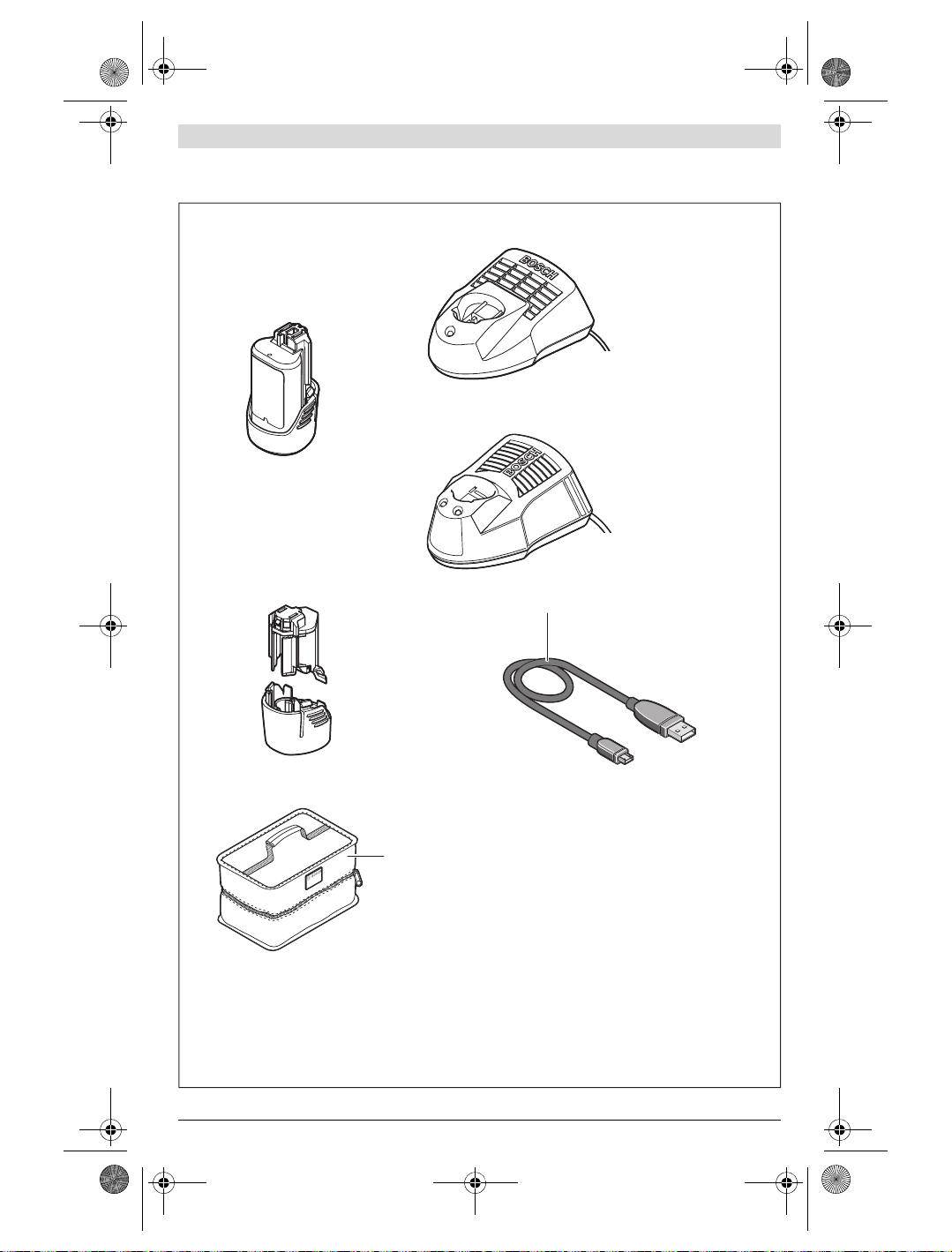
Abgebildete Komponenten
Die Nummerierung der abgebildeten Komponenten bezieht
sich auf die Darstellung des Messwerkzeugs auf der Grafikseite.
1 Schutzkappe für visuelle Kamera und Infrarotsensor
2 Seriennummer
3 Abdeckung Micro-USB-Buchse
4 Micro-USB-Buchse
5 Pfeiltaste auf
6 Taste Messfunktionen „Func“
7 Wechsel Temperaturskala automatisch-fixiert /
Funktionstaste rechts
8 Pfeiltaste rechts
10 Pfeiltaste ab
11 Taste Speichern
12 Pfeiltaste links
13 Taste Galerie/Funktionstaste links
14 Display
15 Visuelle Kamera
16 Infrarot-Sensorbereich
17 Taste Messung einfrieren/weitermessen
18 Akkuschacht
19 Entriegelungstaste Akku/Batterieadapter
20 Verschlusskappe Batterieadapter *
21 Hülle Batterieadapter *
22 Aussparung Hülle
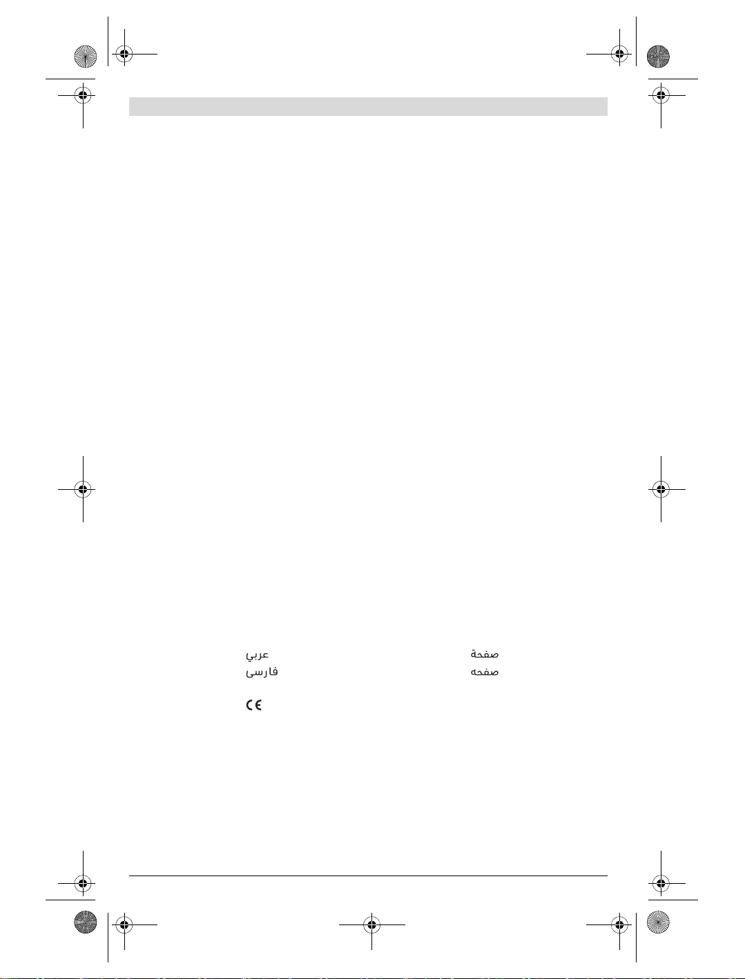
23 Akku *
24 Micro-USB-Kabel
25 Schutztasche *
* Abgebildetes oder beschriebenes Zubehör gehört nicht zum
Standard-Lieferumfang.
Anzeigenelemente
a Datum/Uhrzeit
b Messfunktion
c Anzeige Emissionsgrad
d Anzeige Bluetooth®-Verbindung
e Anzeige WiFi ein-/ausgeschaltet
f Anzeige Ladezustand
g Anzeige maximale Oberflächentemperatur im
h Skala
i Anzeige minimale Oberflächentemperatur im Messbereich
j Symbol Skalenarretierung
k Anzeige Heißpunkt (exemplarisch)
l Fadenkreuz mit Temperaturanzeige
m Anzeige Kaltpunkt (exemplarisch)
n Galeriesymbol
9 Ein-Aus-Taste
Deutsch | 7
Messbereich
Technische Daten
Wärmebildkamera GTC 400 C
Sachnummer
Auflösung Infrarotsensor
Thermische Empfindlichkeit
Spektralbereich
Sichtfeld (FOV)
Fokusentfernung
Fokus
Messbereich Oberflächentemperatur
Zur eindeutigen Identifizierung Ihres Messwerkzeugs dient die Seriennummer 2 auf dem Typenschild.
1) bei einer Umgebungstemperatur von 20– 23 ° C und einem Emissionsgrad von >0,999, Messabstand: 0,3 m, Betriebszeit: > 5 min
2) eingeschränkte Leistung bei Temperaturen <0 ° C
Technische Daten ermittelt mit Akku aus Lieferumfang.
Bosch Power Tools 1 609 92A 3RD | (22.8.17)
3 601 K83 1..
160 x 120
<50mK
8–14μm
53 x 43°
≥0,3m
–10…+400°C
fix
OBJ_BUCH-3136-002.book Page 8 Tuesday, August 22, 2017 6:26 PM
8 | Deutsch
Wärmebildkamera GTC 400 C
Messgenauigkeit (typisch)
Oberflächentemperatur
1)
–10…+10 °C
10…100 ° C
>+100°C
Displaytyp
Displaygröße
Auflösung Display
320 x 240
Bildformat
Gespeicherte Bilder pro Speichervorgang
1 x Wärmebild (Screenshot)
1 x visuelles Echtbild inkl. Temperaturwerten (Metadaten)
Anzahl Bilder im internen Bildspeicher (typisch)
Integrierte visuelle Kamera
Batterien (Alkali-Mangan)
Akku (Li-Ionen)
4 x 1,5 V LR6 (AA) (mit Batterieadapter)
10,8 V/12 V
Betriebsdauer
– Batterien (Alkali-Mangan)
– Akku (Li-Ionen)
USB-Anschluss
Energieversorgung TrackMyTools-Bluetooth®-Modul
–Knopfzelle
– Batterielebensdauer ca.
Bluetooth®
Max. Sendeleistung Bluetooth®
Frequenzband Bluetooth®
CR2450 (3-V-Lithium-Batterie)
60 Monate
Bluetooth® 4.2 (Low Energy)
3,2 mW
2,402 – 2,480 GHz
Drahtlos-Konnektivität
Max. Sendeleistung WiFi
Betriebsfrequenzbereich WiFi
Gewicht entsprechend EPTA-Procedure 01:2014
Maße (Länge x Breite x Höhe)
2,400– 2,483 GHz
233 x 95 x 63 mm
30 mW
0,54 kg
Schutzart (außer Batteriefach)
erlaubte Umgebungsbedingungen
– Ladetemperatur
– Betriebstemperatur
2)
– Lagertemperatur
– Relative Luftfeuchte (nicht kondensierend)
empfohlene Akkus
0…+45°C
–10…+45 °C
–20…+70 °C
20… 80 %
GBA 10,8 V
GBA 12 V
empfohlene Ladegeräte
AL 11.. CV
GAL 12.. CV
Zur eindeutigen Identifizierung Ihres Messwerkzeugs dient die Seriennummer 2 auf dem Typenschild.
1) bei einer Umgebungstemperatur von 20– 23 ° C und einem Emissionsgrad von >0,999, Messabstand: 0,3 m, Betriebszeit: > 5 min
2) eingeschränkte Leistung bei Temperaturen <0 ° C
Technische Daten ermittelt mit Akku aus Lieferumfang.
±3 ° C
±3 ° C
±3 %
TFT
3,5″
.jpg
500
2,0 h
5,0 h
1.1
WiFi
IP 53
1 609 92A 3RD | (22.8.17) Bosch Power Tools
OBJ_BUCH-3136-002.book Page 9 Tuesday, August 22, 2017 6:26 PM
Deutsch | 9
Montage
Energieversorgung
Das Messwerkzeug kann entweder mit handelsüblichen
Batterien (AA-Batterien Typ LR6 oder vergleichbar) oder mit
einem Bosch Li-Ionen-Akku betrieben werden.
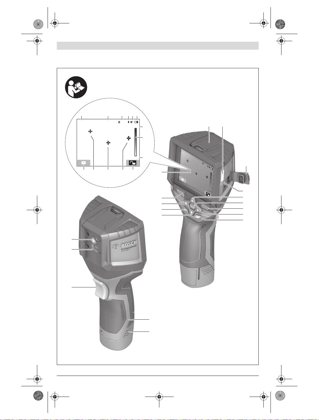
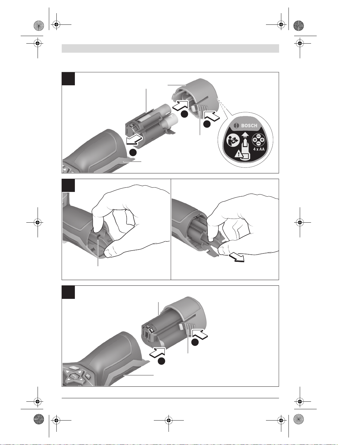
Betrieb mit Batterieadapter (herausnehmbar)
(siehe Bild A)
Die Batterien werden in den Batterieadapter eingesetzt.
Der Batterieadapter ist ausschließlich zum Gebrauch
in dafür vorgesehenen Bosch-Messwerkzeugen bestimmt und darf nicht mit Elektrowerkzeugen verwendet werden.
Zum Einsetzen der Batterien schieben Sie die Hülle des Batterieadapters 21 in den Akkuschacht 18. Legen Sie die Batterien entsprechend der Abbildung auf der Verschlusskappe 20
in die Hülle ein. Schieben Sie die Verschlusskappe über die
Hülle, bis diese spürbar einrastet und bündig am Griff des
Messwerkzeugs anliegt.
Zum Entnehmen der Batterien drücken Sie die
Entriegelungstasten 19 der Verschlusskappe 20
und ziehen die Verschlusskappe ab. Achten Sie dabei darauf, dass die Batterien nicht herausfallen.
Halten Sie das Messwerkzeug dazu mit dem Akku-
schacht 18 nach oben gerichtet. Entnehmen Sie
die Batterien. Um die innen liegende Hülle 21 aus dem Akkuschacht 18 zu entfernen, greifen Sie in die Aussparung der
Hülle 22 und ziehen diese bei leichtem Druck auf die Seitenwand aus dem Messwerkzeug heraus (siehe Bild B).
Hinweis: Nutzen Sie zum Entnehmen des Akkus kein Werkzeug (z.B. einen Schraubendreher), da die Hülle sonst brechen könnte.
Ersetzen Sie immer alle Batterien gleichzeitig. Verwenden Sie
nur Batterien eines Herstellers und mit gleicher Kapazität.
Nehmen Sie die Batterien aus dem Messwerkzeug,
wenn Sie es längere Zeit nicht benutzen. Die Batterien
können bei längerer Lagerung korrodieren und sich selbst
entladen.
Betrieb mit Akku (siehe Bild C)
Hinweis: Der Gebrauch von nicht für Ihr Messwerkzeug geeig-
neten Akkus kann zu Fehlfunktionen oder zur Beschädigung
des Messwerkzeugs führen.
Hinweis: Der Akku wird teilgeladen ausgeliefert. Um die volle
Leistung des Akkus zu gewährleisten, laden Sie vor dem ersten
Einsatz den Akku vollständig im Ladegerät auf.
Benutzen Sie nur die in den technischen Daten aufge-
führten Ladegeräte. Nur diese Ladegeräte sind auf den
bei Ihrem Messwerkzeug verwendbaren Li-Ionen-Akku
abgestimmt.
Der Li-Ionen-Akku kann jederzeit aufgeladen werden, ohne
die Lebensdauer zu verkürzen. Eine Unterbrechung des Ladevorganges schädigt den Akku nicht.
Drücken Sie nach dem automatischen Abschalten des
Messwerkzeuges nicht weiter auf die Ein-Aus-Taste.
Der Akku kann beschädigt werden.
Bosch Power Tools 1 609 92A 3RD | (22.8.17)
Zum Einsetzen des geladenen Akkus 23 schieben Sie diesen
in den Akkuschacht
am Griff des Messwerkzeugs anliegt.
Zum Entnehmen des Akkus 23 drücken Sie die Entriegelungstasten 19 und ziehen den Akku aus dem Akkuschacht
18. Wenden Sie dabei keine Gewalt an.
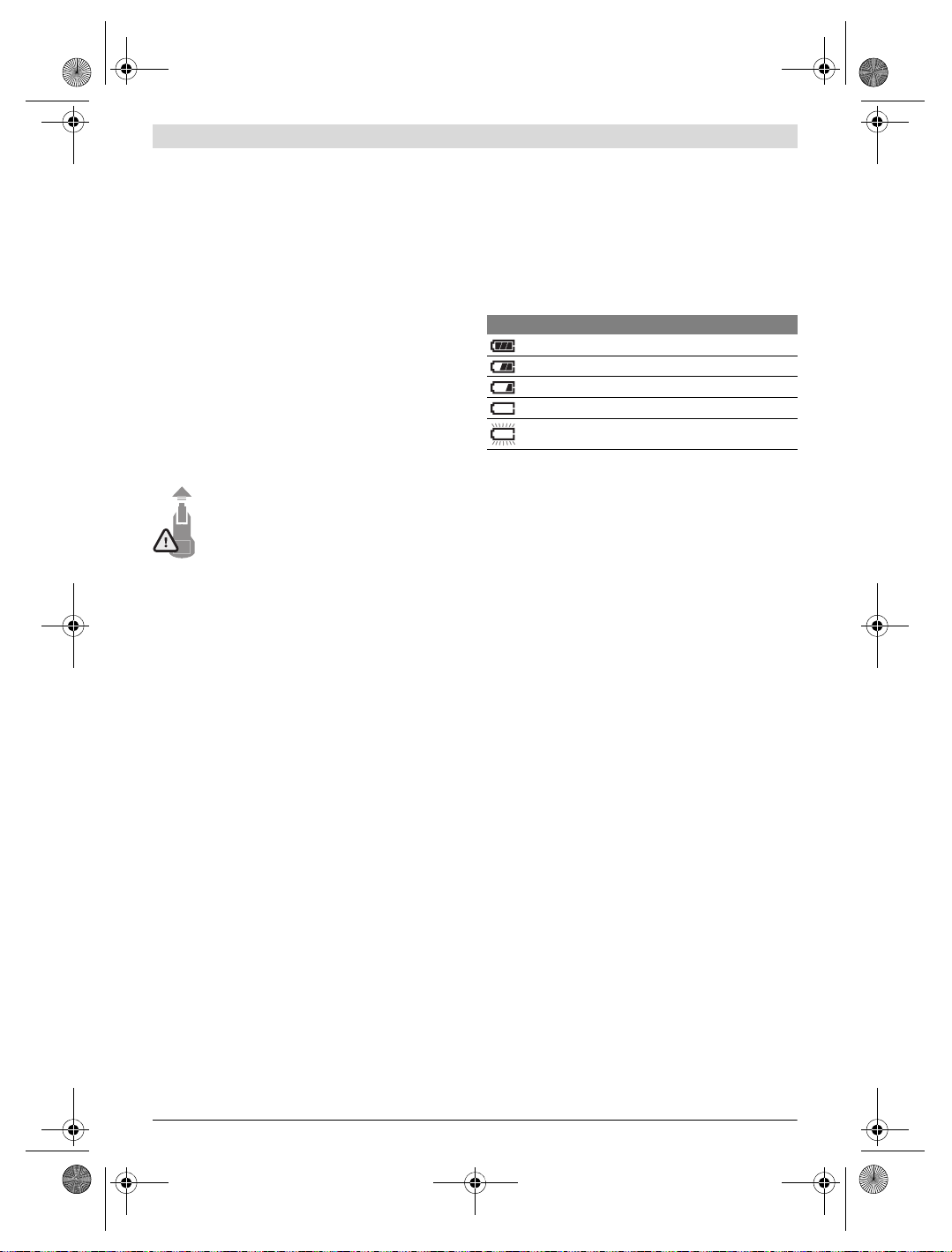
Ladezustandsanzeige
Die Ladezustandsanzeige f im Display zeigt den Ladezustand
der Batterien bzw. des Akkus 23 an.
Anzeige Kapazität
18, bis er spürbar einrastet und bündig
>2/3
≤2/3
≤1/3
≤10%
Batterien bzw. Akku wechseln
Betrieb
Schützen Sie das Messwerkzeug vor Nässe und direkter
Sonneneinstrahlung.
Setzen Sie das Messwerkzeug keinen extremen Tempe-
raturen oder Temperaturschwankungen aus. Lassen Sie
es z.B. nicht längere Zeit im Auto liegen. Lassen Sie das
Messwerkzeug bei größeren Temperaturschwankungen erst
austemperieren, bevor Sie es in Betrieb nehmen. Bei extremen Temperaturen oder Temperaturschwankungen kann
die Präzision des Messwerkzeugs beeinträchtigt werden.
Achten Sie auf eine korrekte Akklimatisierung des
Messwerkzeugs. Bei starken Temperaturschwankungen
oder sich stark ändernden Umgebungsbedingungen könnte die Messgenauigkeit des Messgeräts so lange beeinträchtigt sein, bis es wieder voll akklimatisiert ist.
Vermeiden Sie heftige Stöße oder Stürze des Mess-
werkzeuges. Nach starken äußeren Einwirkungen und bei
Auffälligkeiten in der Funktionalität sollten Sie das Messwerkzeug bei einer autorisierten Bosch-Kundendienststelle überprüfen lassen.
Inbetriebnahme
Ein-/Ausschalten
Klappen Sie zum Messen die Schutzkappe 1 auf. Achten Sie
während der Arbeit darauf, dass der Infrarot-Messbereich nicht verschlossen oder verdeckt wird.
Zum Einschalten des Messwerkzeugs drücken Sie die Ein-Aus-
Taste 9. Im Display 14 erscheint eine Startsequenz. Nach der
Startsequenz beginnt das Messwerkzeug sofort mit der Messung und führt diese kontinuierlich bis zum Ausschalten fort.
Hinweis: In den ersten Minuten kann es vorkommen, dass
das Messwerkzeug sich öfters selbst abgleicht, da sich Sensor- und Umgebungstemperatur noch nicht angeglichen
haben. Die erneute Kalibrierung ermöglicht eine präzise Messung. Während der Kalibrierung friert das Wärmebild kurz ein.
Zum Ausschalten des Messwerkzeugs drücken Sie die EinAus-Taste erneut. Das Messwerkzeug speichert alle Einstellungen und schaltet sich dann aus. Schließen Sie die Schutzkappe 1 zum sicheren Transport des Messwerkzeugs.
OBJ_BUCH-3136-002.book Page 10 Tuesday, August 22, 2017 6:26 PM
10 | Deutsch
Im Einstellungsmenü können Sie wählen, ob und nach welcher
Zeit sich das Messwerkzeug automatisch ausschalten soll
(siehe „Ausschaltzeit“, Seite 12).
Befinden sich der Akku bzw. das Messwerkzeug außerhalb
der in den Technischen Daten angegebenen Betriebstemperatur, dann schaltet sich das Messwerkzeug nach einer kurzen
Warnung (siehe „Fehler – Ursachen und Abhilfe“, Seite 13)
automatisch ab. Lassen Sie das Messwerkzeug austemperieren und schalten Sie es dann wieder ein.
Um Energie zu sparen, schalten Sie das Messwerkzeug nur
ein, wenn Sie es benutzen.
Messvorbereitung
Emissionsgrad für Oberflächen-Temperaturmessungen
einstellen
Der Emissionsgrad eines Objekts ist vom Material und von der
Struktur seiner Oberfläche abhängig. Er gibt an, ob ein Objekt
(im Vergleich mit anderen Objekten mit gleicher Temperatur)
viel oder wenig Infrarot-Wärmestrahlung aussendet.
Zur Bestimmung der Oberflächentemperatur wird berührungslos die natürliche Infrarot-Wärmestrahlung gemessen,
die das angezielte Objekt aussendet. Für korrekte Messungen
muss der am Messwerkzeug eingestellte Emissionsgrad bei
jeder Messung geprüft und gegebenenfalls an das Messobjekt angepasst werden.
Sie können einen der voreingestellten Emissionsgrade auswählen oder einen genauen Zahlenwert eingeben. Stellen Sie
den gewünschten Emissionsgrad über das Menü
„Messung“ >„Emissionsgrad“ ein (siehe Seite 12).
Korrekte Temperaturmessungen sind nur möglich,
wenn der eingestellte Emissionsgrad und der Emissionsgrad des Objekts übereinstimmen.
Farbunterschiede können auf unterschiedliche Temperaturen und/oder auf unterschiedliche Emissionsgrade zurückzuführen sein. Bei stark unterschiedlichen Emissionsgraden
können die angezeigten Temperaturunterschiede deutlich
von den realen abweichen.
Befinden sich mehrere Messobjekte aus unterschiedlichem
Material bzw. unterschiedlicher Struktur im Messbereich,
dann sind die angezeigten Temperaturwerte nur bei den zum
eingestellten Emissionsgrad passenden Objekten verbindlich. Bei allen anderen Objekten (mit anderen Emissionsgraden) können die angezeigten Farbunterschiede als Hinweis
auf Temperaturrelationen genutzt werden.
Material Emissionsgrad
(Anhaltswert 0°C…100°C)
Beton 0,93
Putz/Mörtel 0,93
Ziegel 0,93
Dachpappe 0,93
Heizkörperlack 0,93
Holz 0,91
Linoleum 0,88
Papier 0,89
Hinweise zu den Messbedingungen
Stark reflektierende oder glänzende Oberflächen (z.B. glänzende Fliesen oder blanke Metalle) können die angezeigten
Ergebnisse verfälschen bzw. beeinträchtigen. Kleben Sie bei
Bedarf die Messfläche mit einem dunklen, matten Klebeband,
das gut wärmeleitend ist, ab. Lassen Sie das Band kurz auf der
Oberfläche austemperieren.
Achten Sie bei reflektierenden Oberflächen auf einen günstigen Messwinkel, damit reflektierte Wärmestrahlung von
anderen Objekten das Ergebnis nicht verfälscht. Zum Beispiel
kann bei Messungen senkrecht von vorn die Reflexion Ihrer
eigenen Körperwärme die Messung beeinträchtigen. Bei
einer ebenen Fläche könnten so die Umrisse und Temperatur
Ihres Körpers angezeigt werden (reflektierter Wert), welche
nicht der eigentlichen Temperatur der gemessenen Oberfläche entsprechen (emittierter Wert bzw. realer Wert der Oberfläche).
Die Messung durch transparente Materialien (z.B. Glas oder
transparente Kunststoffe) hindurch ist prinzipbedingt nicht
möglich.
Die Messergebnisse werden umso genauer und zuverlässiger,
je besser und stabiler die Messbedingungen sind.
Die Infrarot-Temperaturmessung wird durch Rauch, Dampf/
hohe Luftfeuchtigkeit oder staubige Luft beeinträchtigt.
Hinweise für eine bessere Genauigkeit der Messungen:
– Gehen Sie so nah wie möglich an das Messobjekt heran,
um Störfaktoren zwischen Ihnen und der Messfläche zu
minimieren.
– Lüften Sie Innenräume vor der Messung, insbesondere
wenn die Luft verschmutzt oder sehr dampfig ist.
Lassen Sie den Raum nach dem Lüften eine Weile austemperieren, bis er die übliche Temperatur wieder erreicht
hat.
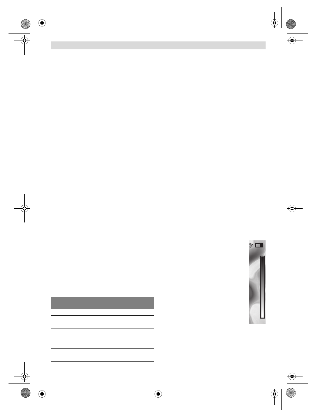
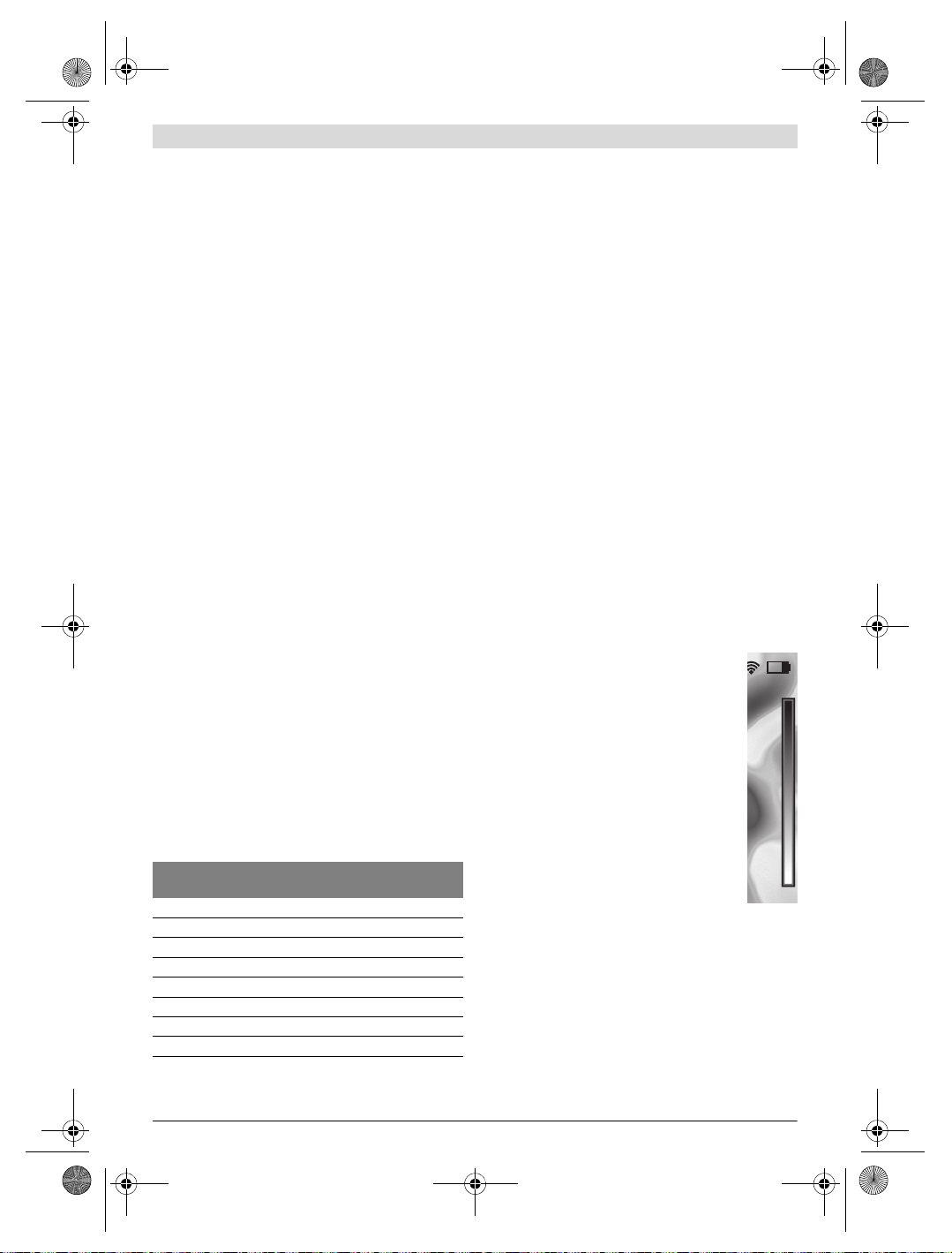
Zuordnung der Temperaturen anhand der Skala
Auf der rechten Seite des Displays wird Ihnen eine
Skala angezeigt. Die Werte am oberen und unteren Ende orientieren sich an der im Wärmebild
erfassten Maximal- bzw. Minimaltemperatur. Die
Zuteilung einer Farbe zu einem Temperaturwert
im Bild erfolgt gleichmäßig verteilt (linear).
Mithilfe der unterschiedlichen Farbtöne können
somit Temperaturen innerhalb dieser beiden
Randwerte zugeordnet werden. Eine Temperatur,
welche genau zwischen dem Maximal- und dem
Minimalwert liegt, kann so beispielsweise dem
mittleren Farbbereich der Skala zugeordnet
werden.
Zur Temperaturbestimmung eines konkreten
Bereiches bewegen Sie das Messgerät, sodass
das Fadenkreuz mit Temperaturanzeige l auf den
gewünschten Punkt bzw. Bereich gerichtet ist.
In der automatischen Einstellung wird das Farbspektrum
der Skala stets auf den gesamten Messbereich innerhalb der
Maximal- bzw. Minimaltemperatur linear (= gleichmäßig)
verteilt.
Die Wärmebildkamera zeigt alle gemessenen Temperaturen
im Messbereich im Verhältnis zueinander an. Wird in einem
32,5 °C
21,8 °C
1 609 92A 3RD | (22.8.17) Bosch Power Tools

OBJ_BUCH-3136-002.book Page 11 Tuesday, August 22, 2017 6:26 PM
Bereich, beispielsweise in einer farbigen Darstellung, die
Wärme in der Farbpalette bläulich angezeigt, bedeutet dies,
dass die bläulichen Bereiche zu den kälteren Messwerten im
aktuellen Messbereich gehören. Diese Bereiche können aber
dennoch in einem Temperaturbereich liegen, der unter Umständen zu Verletzungen führen kann. Achten Sie deshalb immer auf die angezeigten Temperaturen an der Skala bzw. direkt am Fadenkreuz.
Funktionen
Anpassen der Farbdarstellung
Je nach Messsituation können unterschiedliche Farbpaletten
die Analyse des Wärmebildes erleichtern und Objekte oder
Sachverhalte deutlicher im Display abbilden. Die gemessenen Temperaturen werden hierdurch nicht beeinflusst. Es ändert sich lediglich die Darstellung der Temperaturwerte.
Zum Wechseln der Farbpalette bleiben Sie im Messmodus
und drücken die Pfeiltasten rechts 8 oder links 12.
Überlagerung von Wärme- und Echtbild
Für eine bessere Orientierung (= räumliche Zuordnung des
angezeigten Wärmebildes) kann bei ausgeglichenen Temperaturbereichen zusätzlich ein visuelles Echtbild hinzugeschaltet werden.
Hinweis: Die Überlagerung von Echt- und Wärmebild ist bei
einer Distanz von 0,55 m genau. Bei abweichenden Entfernungen zum Messobjekt kann es zu einem Versatz zwischen
Echt- und Wärmebild kommen.
Die Wärmebildkamera bietet Ihnen folgende Möglichkeiten:
– 100 % Infrarotbild
Es wird ausschließlich das Wärmebild angezeigt.
– Bild in Bild
Das angezeigte Wärmebild wird beschnitten und der
umliegende Bereich wird als Echtbild angezeigt. Diese
Einstellung verbessert die örtliche Zuordnung des Messbereiches.
– Transparenz
Das angezeigte Wärmebild wird leicht transparent über
das Echtbild gelegt. So können Objekte besser erkannt
werden.
Durch Drücken der Pfeiltasten oben 5 oder unten 10 können
Sie die Einstellung anpassen.
Fixieren der Skala
Die Anpassung der Farbverteilung im Wärmebild erfolgt automatisch, kann jedoch durch Drücken der Funktionstaste
rechts 7 eingefroren werden. Dies ermöglicht die Vergleichbarkeit von Wärmebildern, die unter unterschiedlichen Temperaturbedingungen aufgenommen wurden (z.B. bei der
Überprüfung von mehreren Räumen auf Wärmebrücken).
Um die Skala wieder auf automatisch zu schalten, drücken Sie
die Funktionstaste rechts 7 erneut. Die Temperaturen verhalten sich nun wieder dynamisch und passen sich den gemessenen Minimal- und Maximalwerten an.
Messfunktionen
Um weitere Funktionen aufzurufen, die Ihnen bei der Anzeige
behilflich sein können, drücken Sie die Taste „Func“ 6. Navi-
gieren Sie in den angezeigten Optionen mit rechts/links, um
eine Funktion auszuwählen. Wählen Sie eine Funktion aus
und drücken Sie die Taste „Func“ 6 erneut.
Folgende Messfunktionen stehen Ihnen zur Verfügung:
– „Automatik“
Die Farbverteilung im Wärmebild erfolgt automatisch.
– „Wärmesucher“
In dieser Messfunktion werden nur die wärmeren Temperaturen im Messbereich als Wärmebild angezeigt. Der
Bereich außerhalb dieser wärmeren Temperaturen wird
als Echtbild in Graustufen angezeigt, um farbige Objekte
nicht fälschlicherweise mit Temperaturen in Verbindung
zu bringen (z.B. rotes Kabel in Schaltschrank bei Suche
nach überhitzten Bauelementen). Passen Sie die Skala mit
den Tasten oben 5 und unten 10 an. Der angezeigte Temperaturbereich wird dadurch erweitert bzw. verringert.
Das Gerät misst Minimal- und Maximaltemperaturen weiterhin mit und zeigt diese an den Enden der Skala an. Sie
können aber steuern, welcher Temperaturbereich als Wärmebild farbig eingeblendet werden soll.
– „Kältesucher“
In dieser Messfunktion werden nur die kälteren Temperaturen im Messbereich als Wärmebild angezeigt. Der
Bereich außerhalb dieser kälteren Temperaturen wird als
Echtbild in Graustufen angezeigt, um farbige Objekte nicht
fälschlicherweise mit Temperaturen in Verbindung zu bringen (z.B. blauer Fensterrahmen bei Suche nach fehlerhafter Isolierung). Passen Sie die Skala mit den Tasten oben 5
und unten 10 an. Der angezeigte Temperaturbereich wird
dadurch erweitert bzw. verringert.
Das Gerät misst Minimal- und Maximaltemperaturen weiterhin mit und zeigt diese an den Enden der Skala an. Sie
können aber steuern, welcher Temperaturbereich als Wärmebild farbig eingeblendet werden soll.
– „Manuell“
Werden stark abweichende Temperaturen im Wärmebild
gemessen (z.B. Heizkörper als heißes Objekt bei Untersuchung von Wärmebrücken), so verteilen sich die zur
Verfügung stehenden Farben auf eine hohe Anzahl von
Temperaturwerten im Bereich zwischen Maximal- und
Minimaltemperatur. Dies kann dazu führen, dass feine
Temperaturunterschiede nicht mehr detailliert angezeigt
werden können. Um eine detailreiche Darstellung der
Fokustemperatur zu erreichen, gehen Sie folgendermaßen
vor: Nachdem Sie in den Modus „Manuell“ gewechselt
haben, können Sie die Maximal- bzw. Minimaltemperatur
einstellen. So können Sie den Temperaturbereich festlegen, welcher für Sie relevant ist und in welchem Sie feine
Unterschiede erkennen möchten. Die Einstellung Reset
passt die Skala wieder automatisch an die gemessenen
Werte im Sichtfeld des Infrarotsensors an.
Deutsch | 11
Bosch Power Tools 1 609 92A 3RD | (22.8.17)

OBJ_BUCH-3136-002.book Page 12 Tuesday, August 22, 2017 6:26 PM
12 | Deutsch
Hauptmenü
Um zum Hauptmenu zu gelangen, drücken Sie die Taste
„Func“ 6 zum Aufrufen der Messfunktionen. Drücken Sie nun
die Funktionstaste rechts 7.
– „Messung“
– „Emissionsgrad“ c:
Für einige der häufigsten Materialien stehen gespeicherte
Emissionsgrade zur Auswahl. Wählen Sie im Menüpunkt
„Material“ das passende Material aus. Der dazugehörige
Emissionsgrad wird in der Zeile darunter angezeigt.
Wenn Ihnen der genaue Emissionsgrad Ihres Messobjekts bekannt ist, können Sie diesen auch als Zahlenwert
im Menüpunkt „Emissionsgrad“ einstellen.
– „Reflektierte Temperatur“:
Die Einstellung dieses Parameters verbessert das Messergebnis besonders bei Materialien mit niedrigem Emissionsgrad (= hoher Reflexion). Meist entspricht die reflektierte Temperatur der Umgebungstemperatur.
Wenn Objekte mit stark abweichenden Temperaturen in
der Nähe stark reflektierender Objekte die Messung beeinflussen können, sollte dieser Wert angepasst werden.
– „Anzeige“
– „Heißpunkt“ k: „AN/AUS“
In dieser Funktion wird der heißeste Punkt (= Messpixel) im Messbereich automatisch durch ein rotes
Fadenkreuz im Wärmebild markiert. Dies kann es Ihnen
erleichtern, eine kritische Stelle zu erkennen, z.B. eine
lose Klemme im Schaltschrank.
– „Kaltpunkt“ m: „AN/AUS“
Der kälteste Punkt (= Messpixel) im Messbereich wird
Ihnen automatisch durch ein blaues Fadenkreuz im Wärmebild markiert. Dies kann es Ihnen erleichtern, eine
kritische Stelle zu erkennen, z.B. eine undichte Stelle in
einer Dämmung.
– „Fadenkreuz“ l: „AN/AUS“
Das Fadenkreuz wird mittig im Wärmebild angezeigt und
zeigt Ihnen den gemessenen Temperaturwert an dieser
Stelle an.
– „Skala“ h: „AN/AUS“
– „WiFi“: „AN/AUS“
(siehe „Datenübertragung“, Seite 13)
– „Track My Tools“: „AN/AUS“
(siehe „TrackMyTools“, Seite 14)
– „Gerät“
– „Sprache“
Unter diesem Menüpunkt können Sie die Sprache aller
Anzeigen anpassen.
– „Zeit & Datum“ a
Für die Änderung von Datum und Zeit in der Anzeige rufen Sie das Untermenü „Zeit & Datum“ auf. In diesem
Untermenü können Sie außerdem das Datums- und Zeitformat ändern.
Zum Verlassen des Untermenüs „Zeit & Datum“ drücken Sie entweder die linke Funktionstaste 13 unter
dem Haken-Symbol, um die Einstellungen zu speichern,
oder die rechte Funktionstaste 7 unter dem Kreuz-Symbol, um die Änderungen zu verwerfen.
– „Tonsignale“: „AN/AUS“
– „Ausschaltzeit“
– „Alle Bilder löschen“
– „Geräteinformationen“
Um ein beliebiges Menü zu verlassen und zum Standard-Anzeigenbildschirm zurückzukehren, können Sie auch die Taste
17 drücken.
Dokumentation von Messergebnissen
Messergebnisse speichern
Direkt nach dem Einschalten beginnt das Messwerkzeug mit
der Messung und führt diese kontinuierlich bis zum Ausschalten fort.
Um ein Bild zu speichern, richten Sie die Kamera auf das gewünschte Messobjekt und drücken Sie die Taste Speichern
11. Das Bild wird im internen Speicher der Kamera abgelegt.
Alternativ drücken Sie die Taste Messung einfrieren 17. Die
Messung wird eingefroren und Ihnen im Display angezeigt.
Dies ermöglicht Ihnen eine ruhige Betrachtung des Bildes.
Möchten Sie das eingefrorene Bild nicht abspeichern, gelangen Sie mit der Taste 17 wieder in den Messmodus. Wenn Sie
das Bild im internen Speicher der Kamera ablegen möchten,
drücken Sie die Taste Speichern 11.
Abrufen gespeicherter Bilder
Zum Abrufen gespeicherter Wärmebilder gehen Sie wie folgt
vor:
– Drücken Sie die Funktionstaste links 13. Im Display
erscheint nun das zuletzt gespeicherte Foto.
– Um zwischen den gespeicherten Wärmebildern zu wech-
seln, drücken Sie die Pfeiltasten rechts 8 oder links 12.
Löschen gespeicherter Bilder
Zum Löschen einzelner Wärmebilder gehen Sie in die Galerieansicht:
– Drücken Sie die rechte Funktionstaste 7 unter dem Papier-
korb-Symbol.
– Bestätigen Sie den Vorgang mit der linken Funktionstaste
13 oder brechen Sie den Löschvorgang durch Drücken der
rechten Funktionstaste 7 unter dem Abbrechen-Symbol ab.
Unter diesem Menüpunkt können Sie die Signaltöne
ein-/ausschalten.
Unter diesem Menüpunkt können Sie das Zeitintervall
wählen, nach dem sich das Messwerkzeug automatisch
abschalten soll, wenn keine Taste gedrückt wird. Sie
können die automatische Abschaltung auch deaktivieren, indem Sie die Einstellung „Nie“ wählen.
Unter diesem Menüpunkt können Sie alle Dateien, die
sich im internen Speicher befinden, auf einmal löschen.
Drücken Sie die Pfeiltaste rechts 8 für „mehr …“, um in
das Untermenü zu gelangen. Drücken Sie dann entweder die linke Funktionstaste 13 unter dem Haken-Symbol, um alle Dateien zu löschen, oder die rechte Funktionstaste 7 unter dem Kreuz-Symbol, um den Vorgang
abzubrechen.
Unter diesem Menüpunkt können Sie Informationen
über das Messwerkzeug abrufen. Sie finden dort die
Seriennummer des Messwerkzeugs und die installierte
Software-Version.
1 609 92A 3RD | (22.8.17) Bosch Power Tools
OBJ_BUCH-3136-002.book Page 13 Tuesday, August 22, 2017 6:26 PM
Alle Bilder löschen
Im Menü „Alle Bilder löschen“ können Sie alle Dateien, die
sich im internen Speicher befinden, auf einmal löschen.
Drücken Sie die Taste „Func“ 6 zum Aufrufen der Messfunk-
tionen. Drücken Sie nun die rechte Funktionstaste 7 und wählen Sie „Gerät“ > „Alle Bilder löschen“ aus. Drücken Sie die
Pfeiltaste rechts 8, um in das Untermenü zu gelangen. Drücken Sie dann entweder die linke Funktionstaste 13 unter
dem Haken-Symbol, um alle Dateien zu löschen, oder die
rechte Funktionstaste 7 unter dem Kreuz-Symbol, um den
Vorgang abzubrechen.
Datenübertragung
Datenübertragung über USB-Schnittstelle
Öffnen Sie die Abdeckung der Micro-USB-Buchse 3. Verbinden Sie die Micro-USB-Buchse des Messwerkzeugs über das
mitgelieferte Micro-USB-Kabel mit Ihrem PC oder mobilen
Computer.
Schalten Sie die Wärmebildkamera nun mit der Taste 9 ein.
Öffnen Sie den Dateibrowser und wählen Sie das Laufwerk
„BOSCH GTC 400 C“ aus. Die gespeicherten JPG-Dateien
können vom internen Speicher des Messwerkzeugs kopiert,
auf Ihren Rechner verschoben oder gelöscht werden.
Sobald Sie den gewünschten Vorgang beendet haben, trennen Sie das Laufwerk standardmäßig ab und schalten dann
die Wärmebildkamera mit der Taste 9 wieder aus.
Entfernen Sie das Micro-USB-Kabel während des Messbetriebs und schließen Sie die Abdeckung 3.
Achtung: Melden Sie das Laufwerk immer zuerst aus Ihrem
Betriebssystem ab (Laufwerk auswerfen), da sonst der interne Speicher der Wärmebildkamera beschädigt werden kann.
Halten Sie die Abdeckung der USB-Schnittstelle immer geschlossen, damit kein Staub oder Spritzwasser in das Gehäuse eindringen kann.
Hinweis: Verbinden Sie das Messwerkzeug nur mit einem PC
oder Notebook. Das Gerät könnte beschädigt werden, wenn
Sie es mit einem anderen Gerät verbinden.
Hinweis: Die Micro-USB-Schnittstelle dient ausschließlich
der Datenübertragung – Batterien und Akkus können
darüber nicht geladen werden.
Nachbearbeitung der Wärmebilder
Die gespeicherten Wärmebilder können Sie auf Ihrem Rechner unter einem Windows-Betriebssystem nachbearbeiten.
Laden Sie hierzu die GTC-Transfer-Software von der Produktseite der Wärmebildkamera unter
www.bosch-professional.com/gtc herunter.
Datenübertragung über WiFi
Das Messwerkzeug ist mit einem WiFi-Modul ausgestattet,
welches die drahtlose Übertragung der gespeicherten Bilder
von Ihrer Wärmebildkamera auf ein mobiles Endgerät ermöglicht.
Hierzu wird als Softwareschnittstelle die Applikation (App)
„Measuring Master“ benötigt. Diese können Sie je nach
Endgerät in den entsprechenden Stores herunterladen:
Die Anwendung „Measuring Master“ ermöglicht Ihnen,
neben der drahtlosen Datenübertragung Ihrer Bilder, einen
erweiterten Funktionsumfang und vereinfacht die Nachbearbeitung sowie die Weiterleitung der Messdaten (z.B. per
E-Mail). Informationen zur erforderlichen Systemvoraussetzung für eine WiFi-Verbindung finden Sie auf der BoschInternetseite unter „www.bosch-professional.com/gtc“.
Um die WiFi-Verbindung am Messwerkzeug zu aktivieren/deaktivieren, rufen Sie das Hauptmenü auf, navigieren mit den
Tasten zur Auswahl „WiFi“ und aktivieren/deaktivieren diese.
Im Display erscheint die Anzeige e. Stellen Sie sicher, dass
die WiFi-Schnittstelle an Ihrem mobilen Endgerät aktiviert ist.
Nach dem Start der Bosch-Applikation kann (bei aktivierten
WiFi-Modulen) die Verbindung zwischen mobilem Endgerät
und Messwerkzeug hergestellt werden. Folgen Sie hierzu den
Anweisungen der Anwendung „Measuring Master“.
Deutsch | 13
Fehler – Ursachen und Abhilfe
Im Falle einer Störung führt das Gerät einen Neustart durch und kann im Anschluss wieder verwendet werden. Andernfalls hilft
Ihnen die unten stehende Übersicht bei dauerhaften Fehlermeldungen.
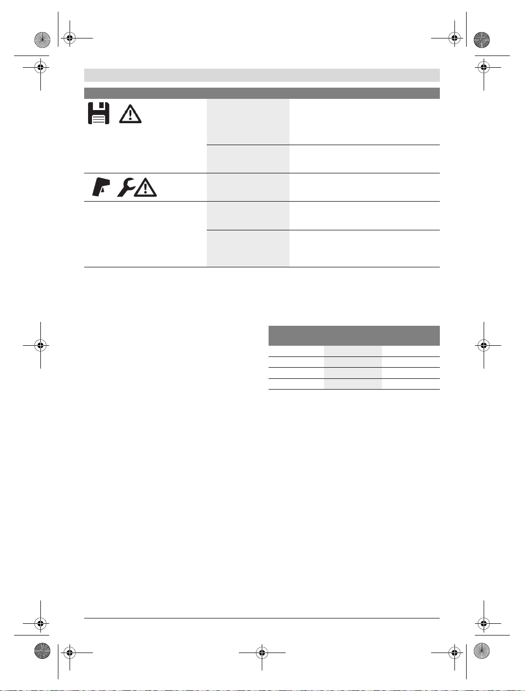
Fehler Ursache Abhilfe
Messwerkzeug kann nicht eingeschaltet
werden.
Bosch Power Tools 1 609 92A 3RD | (22.8.17)
Akku bzw. Batterien leer Laden Sie den Akku bzw. wechseln Sie die Batterien.
Akku zu warm bzw. zu kalt Lassen Sie den Akku austemperieren bzw. wechseln
Messwerkzeug zu warm
bzw. zu kalt
Sie ihn.
Lassen Sie das Messwerkzeug austemperieren.
OBJ_BUCH-3136-002.book Page 14 Tuesday, August 22, 2017 6:26 PM
14 | Deutsch
Fehler Ursache Abhilfe
Bildspeicher defekt Formatieren Sie den internen Speicher, indem Sie
Bildspeicher voll Übertragen Sie die Bilder bei Bedarf auf ein anderes
Messwerkzeug defekt Senden Sie das Messwerkzeug an eine autorisierte
alle Bilder löschen (siehe „Alle Bilder löschen“,
Seite 13). Besteht das Problem weiterhin, senden
Sie das Messwerkzeug an eine autorisierte BoschKundendienststelle.
Speichermedium (z.B. Computer oder Notebook).
Löschen Sie dann die Bilder im internen Speicher.
Bosch-Kundendienststelle.
Messwerkzeug kann nicht mit einem
Computer verbunden werden.
Messwerkzeug wird nicht
vom Computer erkannt.
Micro-USB-Anschluss oder
Micro-USB-Kabel defekt
Begriffserklärungen
Infrarot-Wärmestrahlung
Die Infrarot-Wärmestrahlung ist eine elektromagnetische
Strahlung, die von jedem Körper ausgesendet wird. Die Menge der Strahlung hängt von der Temperatur und dem Emissionsgrad des Körpers ab.
Emissionsgrad
Der Emissionsgrad eines Objekts ist vom Material und von der
Struktur seiner Oberfläche abhängig. Er gibt an, wie viel Infrarot-Wärmestrahlung das Objekt im Vergleich zu einem idealen
Wärmestrahler (schwarzer Körper, Emissionsgrad =1) abgibt.
Wärmebrücke
Als Wärmebrücke wird ein Objekt bezeichnet, das unerwünscht Wärme nach außen oder innen leitet und sich somit
erheblich von der restlichen bzw. gewünschten Temperatur
einer Wand unterscheidet.
Da die Oberflächentemperatur an Wärmebrücken niedriger
als im übrigen Raum ist, steigt die Schimmelgefahr an diesen
Stellen erheblich.
Reflektierte Temperatur/Reflexivität eines Objektes
Die reflektierte Temperatur sind die Wärmestrahlungen, die
nicht von dem Objekt selbst ausgehen. Abhängig von der
Struktur und dem Material reflektieren sich Umgebungsstrahlungen im zu messenden Objekt und verfälschen somit das
eigentliche Temperaturergebnis.
Prüfen Sie, ob der Treiber auf Ihrem Computer
aktuell ist. Gegebenenfalls ist eine neuere Betriebssystem-Version auf dem Computer notwendig.
Prüfen Sie, ob sich das Messwerkzeug mit einem
anderen Computer verbinden lässt. Wenn nicht, senden Sie das Messwerkzeug an eine autorisierte
Bosch-Kundendienststelle.
Objektabstand
Der Abstand zwischen dem Messobjekt und dem Messgerät
beeinflusst die erfasste Flächengröße pro Pixel. Mit zunehmendem Objektabstand können Sie zunehmend große Objekte erfassen.
Entfernung (m) Größe Infrarot-
0,5
1
2
5
pixel (mm)
3 ~0,5 x 0,4
6 ~1 x 0,75
12 2,05 x 1,5
30 5,1 x 3,8
Infrarotbereich
Breite x Höhe (m)
TrackMyTools
Das eingebaute Bluetooth® Low Energy Module ermöglicht
die Personalisierung und Statusprüfung des Messwerkzeugs
sowie die Übertragung von Einstellungen und Daten basierend auf Bluetooth®-Funktechnologie.
Energieversorgung TrackMyTools-Bluetooth®-Modul
Das Messwerkzeug ist mit einer Knopfzelle ausgestattet, da-
mit es auch ohne eingesetzten Akku 23 bzw. eingesetzte Batterien über TrackMyTools von einem mobilen Endgerät erfasst werden kann.
Weiterführende Informationen erhalten Sie direkt in der App
von Bosch.
Datenübertragung
Das TrackMyTools-Bluetooth®-Modul können Sie in den Geräteeinstellungen an- bzw. ausschalten. Danach sendet es ein
kontinuierliches Signal aus.
Das Sendeintervall des Moduls beträgt acht Sekunden. Je
nach Umgebung können bis zu drei Sendeintervalle benötigt
werden, ehe das Messwerkzeug erkannt wird.
Hinweis: Schalten Sie TrackMyTools aus, we nn Si e sic h in B ereichen aufhalten, wo das Aussenden von Funkwellen untersagt ist, z.B. im Flugzeug.
1 609 92A 3RD | (22.8.17) Bosch Power Tools
OBJ_BUCH-3136-002.book Page 15 Tuesday, August 22, 2017 6:26 PM
Registrierung und Einrichtung der App/Webanwendung
Um TrackMyTools verwenden zu können, müssen Sie sich
zuerst online registrieren.
Öffnen Sie dazu die Webseite www.bosch-trackmytools.com
und registrieren Sie sich. Nach Abschluss der Registrierung
erhalten Sie Ihre Zugangsdaten.
Laden Sie sich die App TrackMyTools über einen entspre-
chenden App-Store (Apple App Store, Google Play Store)
herunter oder rufen Sie die Webanwendung über
https://web.bosch-trackmytools.com auf. Hier können Sie
sich mit Ihren Zugangsdaten anmelden.
Nun können Sie Ihr Inventar mithilfe der App/Webanwendung
anlegen und verwalten.
Hinweis: Führen Sie zuerst das Tutorial der App/Webanwendung vollständig durch. Dadurch erhalten Sie einen besseren
Überblick über die Vorgehensweise beim Anlegen des Inventars und über die Bedienung der Software.
Wartung und Service
Wartung und Reinigung
Lagern und transportieren Sie das Messwerkzeug nur in
einem geeigneten Behältnis wie der Originalverpackung bzw.
der Schutztasche (Zubehör). Kleben Sie keine Aufkleber in
der Nähe des Infrarot-Sensors auf das Messwerkzeug.
Halten Sie das Messwerkzeug stets sauber.
Beim Reinigen darf keine Flüssigkeit in das Messwerkzeug
eindringen.
Versuchen Sie nicht, mit spitzen Gegenständen Schmutz aus
dem Sensor, von der Kamera oder der Empfangslinse zu entfernen, und wischen Sie nicht über Kamera und Empfangslinse (Gefahr von Verkratzen).
Wenn Sie eine erneute Kalibrierung Ihres Messwerkzeugs
wünschen, wenden Sie sich bitte an ein Bosch Servicezentrum (Adressen siehe Abschnitt „Kundendienst und Anwendungsberatung“).
Senden Sie im Reparaturfall das Messwerkzeug in der Originalverpackung oder der Schutztasche (Zubehör) ein.
Die integrierte Knopfzelle darf nur zur Entsorgung von Fachpersonal entnommen werden. Durch das Öffnen der
Gehäuseschale kann das Messwerkzeug zerstört werden.
Drehen Sie die Schrauben am Gehäuse heraus und nehmen
Sie die Gehäuseschale ab, um die Knopfzelle zu entnehmen.
Kundendienst und Anwendungsberatung
Der Kundendienst beantwortet Ihre Fragen zu Reparatur und
Wartung Ihres Produkts sowie zu Ersatzteilen. Explosionszeichnungen und Informationen zu Ersatzteilen finden Sie
auch unter:
www.bosch-pt.com
Das Bosch-Anwendungsberatungs-Team hilft Ihnen gerne bei
Fragen zu unseren Produkten und deren Zubehör.
www.powertool-portal.de, das Internetportal für Handwerker und Heimwerker.
Geben Sie bei allen Rückfragen und Ersatzteilbestellungen
bitte unbedingt die 10-stellige Sachnummer laut Typenschild
des Produkts an.
Deutschland
Robert Bosch Power Tools GmbH
Servicezentrum Elektrowerkzeuge
Zur Luhne 2
37589 Kalefeld – Willershausen
Unter www.bosch-pt.com können Sie online Ersatzteile
bestellen oder Reparaturen anmelden.
Kundendienst: Tel.: (0711) 40040460
Fax: (0711) 40040461
E-Mail: Servicezentrum.Elektrowerkzeuge@de.bosch.com
Anwendungsberatung: Tel.: (0711) 40040460
Fax: (0711) 40040462
E-Mail: kundenberatung.ew@de.bosch.com
Österreich
Unter www.bosch-pt.at können Sie online Ersatzteile
bestellen.
Tel.: (01) 797222010
Fax: (01) 797222011
E-Mail: service.elektrowerkzeuge@at.bosch.com
Schweiz
Unter www.bosch-pt.com/ch/de können Sie online
Ersatzteile bestellen.
Tel.: (044) 8471511
Fax: (044) 8471551
E-Mail: Aftersales.Service@de.bosch.com
Luxemburg
Tel.: +32 2 588 0589
Fax: +32 2 588 0595
E-Mail: outillage.gereedschap@be.bosch.com
Transport
Die verwendbaren Li-Ionen-Akkus unterliegen den Anforderungen des Gefahrgutrechts. Die Akkus können durch den
Benutzer ohne weitere Auflagen auf der Straße transportiert
werden.
Beim Versand durch Dritte (z.B.: Lufttransport oder Spedition) sind besondere Anforderungen an Verpackung und
Kennzeichnung zu beachten. Hier muss bei der Vorbereitung
des Versandstückes ein Gefahrgut-Experte hinzugezogen
werden.
Versenden Sie Akkus nur, wenn das Gehäuse unbeschädigt
ist. Kleben Sie offene Kontakte ab und verpacken Sie den
Akku so, dass er sich nicht in der Verpackung bewegt.
Bitte beachten Sie auch eventuelle weiterführende nationale
Vorschriften.
Entsorgung
Deutsch | 15
Messwerkzeuge, Akkus/Batterien, Zubehör und Verpackungen sollen einer umweltgerechten Wiederverwertung zugeführt werden.
Werfen Sie Messwerkzeuge und Akkus/Batterien
nicht in den Hausmüll!
Bosch Power Tools 1 609 92A 3RD | (22.8.17)
OBJ_BUCH-3136-002.book Page 16 Tuesday, August 22, 2017 6:26 PM
16 | English
Nur für EU-Länder:
Gemäß der europäischen Richtlinie 2012/19/EU müssen
nicht mehr gebrauchsfähige Messwerkzeuge und gemäß der
europäischen Richtlinie 2006/66/EG müssen defekte oder
verbrauchte Akkus/Batterien getrennt gesammelt und einer
umweltgerechten Wiederverwendung zugeführt werden.
Nicht mehr gebrauchsfähige Akkus/Batterien können direkt
abgegeben werden bei:
Deutschland
Recyclingzentrum Elektrowerkzeuge
Osteroder Landstraße 3
37589 Kalefeld
Schweiz
Batrec AG
3752 Wimmis BE
Akkus/Batterien:
Li-Ion:
Bitte beachten Sie die Hinweise im Abschnitt „Transport“,
Seite 15.
Änderungen vorbehalten.
English
Safety Notes
Read and observe all instructions. The inte-
grated protections in the measuring tool may
be compromised if the measuring tool is not
used in accordance with the instructions provided. SAVE THESE INSTRUCTIONS FOR
FUTURE REFERENCE.
Have the measuring tool repaired only through quali-
fied specialists using original spare parts. This ensures
that the safety of the measuring tool is maintained.
Do not operate the measuring tool in explosive environ-
ments, such as in the presence of flammable liquids,
gases or dusts. Sparks can be created in the measuring
tool which may ignite the dust or fumes.
Before any work on the measuring tool itself (e.g.
assembling, maintenance, etc.) as well as when transporting and storing, remove the battery pack or the
batteries from the measuring tool.
Do not open the battery pack. Danger of short-circuiting.
Protect the battery pack against heat, e.g.,
against continuous intense sunlight, fire,
water, and moisture. Danger of explosion.
When battery pack is not in use, keep it away from
other metal objects like paper clips, coins, keys, nails,
screws, or other small metal objects that can make a
connection from one terminal to another. Shorting the
battery terminals together may cause burns or a fire.
Under abusive conditions, liquid may be ejected from
the battery pack; avoid contact. If contact accidentally
occurs, flush with water. If liquid contacts eyes, additionally seek medical help. Liquid ejected from the bat-
tery pack may cause irritations or burns.
In case of damage and improper use of the battery
pack, vapours may be emitted. Provide for fresh air and
seek medical help in case of complaints. The vapours
can irritate the respiratory system.
Recharge only with the charger specified by the manu-
facturer. A charger that is suitable for one type of battery
pack may create a risk of fire when used with another battery pack.
Use the battery pack only in conjunction with your
Bosch measuring tool. This measure alone protects the
battery pack against dangerous overload.
The battery pack can be damaged by pointed objects
such as nails or screwdrivers or by force applied externally. An internal short circuit can occur and the battery
pack can burn, smoke, explode or overheat.
The non-rechargeable battery adapter is intended only
for use in designated Bosch measuring tools and must
not be used with power tools.
Remove the batteries from the measuring tool when not
using it for extended periods. When storing for extended
periods, the batteries can corrode and self-discharge.
Protect the measuring tool, particularly the area
around the camera and infrared lens, against moisture
and snow. The reception lens could fog up and distort the
measurements. Incorrect settings on the tool and other atmospheric influences may make the measurements inaccurate. Objects could be depicted hotter or colder, which
may present a danger if touched.
High temperature differences in a thermal image may
cause even high temperatures to be shown in a colour
associated with low temperatures. Coming into contact
with such an area may cause burns.
Temperature measurements will only be correct if the
emissivity setting and the emissivity of the object match.
Objects could be depicted hotter or colder in temperature
and/or colour, which may present a danger if touched.
Caution! When using the measuring tool with
Bluetooth®, interference with other devices and sys-
tems, airplanes and medical devices (e.g., cardiac
pacemakers, hearing aids) may occur. Also, the possibility of humans and animals in direct vicinity being
harmed cannot be completely excluded. Do not use the
measuring tool with Bluetooth® in the vicinity of medical devices, petrol stations, chemical plants, areas
where there is danger of explosion, and areas subject
to blasting. Do not use the measuring tool with Blue-
tooth® in airplanes. Avoid operation in direct vicinity of
the body over longer periods.
The measuring tool is equipped with a radio interface.
Local operating restrictions, e.g. in airplanes or hospitals, are to be observed.
1 609 92A 3RD | (22.8.17) Bosch Power Tools
OBJ_BUCH-3136-002.book Page 17 Tuesday, August 22, 2017 6:26 PM
English | 17
Product Description and
Specifications
Please unfold the fold-out page with the representation of the
measuring tool and leave it unfolded while reading the operating instructions.
The Bluetooth® word mark and logos are registered
trademarks owned by Bluetooth SIG, Inc. and any use of
such marks by Robert Bosch Power Tools GmbH is under
licence.
Intended Use
This thermal imaging camera is designed for the contactless
measurement of surface temperatures.
The displayed thermal image shows the temperature distribution of the area captured by the infrared lens and therefore
enables temperature deviations to be depicted in different
colours.
When used correctly, this makes it possible to examine areas
and objects in a contactless manner for temperature differences and discrepancies in order to make components and/or
any weaknesses visible, including:
– Thermal insulation and other types of insulation (e.g. locat-
ing thermal bridges)
– Active heating and hot water pipes (e.g. underfloor heat-
ing) in floors and walls
– Overheated electrical components (e.g. fuses or terminals)
– Machine parts (e.g. overheating due to faulty ball bearings)
The measuring tool must not be used for temperature measurement on persons and animals or for other medical purposes.
The measuring tool is not suitable for surface temperature
measurement of gases or liquids.
Product Features
The numbering of the product features shown refers to the
illustration of the measuring tool on the graphic page.
1 Protective cap for visual camera and infrared sensor
2 Serial number
3 Cover, micro USB port
4 Micro USB port
5 Up arrow button
6“Func” measuring functions button
7 Switching temperature scale between automatic and
fixed/right-hand function button
8 Right-hand arrow button
9 On/Off button
10 Down arrow button
11 Save button
12 Left-hand arrow button
13 Gallery button/left-hand function button
14 Display
15 Visual camera
16 Infrared sensor area
17 Freeze measurement/continue measuring button
18 Battery port
19 Release button for battery pack/battery adapter
20 Battery adapter sealing cap *
21 AA battery adapter cover *
22 Cover recess
23 Battery pack *
24 Micro USB cable
25 Protective pouch *
* The accessories illustrated or described are not included as
standard delivery.
Display Elements
a Date/time
b Measuring function
c Emissivity display
d Indicator for Bluetooth® connection
e WiFi switched on/off indicator
f Charge-control indicator
g Display of maximum surface temperature in the
measurement range
h Scale
i Display of minimum surface temperature in the
measurement range
j Scale lock symbol
k Hotspot display (example)
l Crosshairs with temperature display
m Coldspot display (example)
n Gallery symbol
Technical Data
Thermal imaging camera GTC 400 C
Article number
Resolution of infrared sensor
Thermal sensitivity
Spectral range
Field of view (FOV)
The measuring tool can be clearly identified with the serial number 2 on the type plate.
1) at an ambient temperature of 20– 23 ° C and an emissivity of >0.999, measuring distance: 0.3 m, operating time: > 5 min
2) limited performance at temperatures <0 °C
Technical data determined with battery from delivery scope.
3 601 K83 1..
160 x 120
<50mK
8–14μm
53 x 43°
Bosch Power Tools 1 609 92A 3RD | (22.8.17)

OBJ_BUCH-3136-002.book Page 18 Tuesday, August 22, 2017 6:26 PM
18 | English
Thermal imaging camera GTC 400 C
Focus distance ≥0.3m
Focus
Surface temperature measurement range
Measuring accuracy (typical)
Surface temperature
1)
–10…+400°C
–10…+10 °C
10…100 ° C
>+100°C
Display type
Display size
Display resolution
320 x 240
Image format
Images saved per saving process
1 x thermal image (screenshot)
1 x real visual image incl. temperature values (metadata)
Number of images in internal image memory (typical)
Integrated visual camera
Batteries (alkali-manganese)
Battery pack (lithium-ion)
4 x 1.5 V LR6 (AA) (with battery adapter)
10.8 V/12 V
Battery life
– Batteries (alkali-manganese)
–Battery pack (lithium-ion)
USB port
TrackMyTools Bluetooth® module power supply
– Button cell
– Battery service life, approx.
Bluetooth®
Max. Bluetooth® transmission power
Frequency band Bluetooth®
CR2450 (3 V lithium battery)
60 months
Bluetooth® 4.2 (Low Energy)
3.2 mW
2.402 – 2.480 GHz
Wireless connectivity
Max. WiFi transmission power
WiFi operating frequency range
Weight according to EPTA-Procedure 01:2014
Dimensions (length x width x height)
2.400– 2.483 GHz
233 x 95 x 63 mm
30 mW
0.54 kg
Degree of protection (excluding battery compartment)
Permitted environmental conditions
–Charging temperature
–Operating temperature
2)
–Storage temperature
– Relative humidity (non-condensing)
Recommended batteries
0…+45°C
–10…+45 °C
–20…+70 °C
20… 80 %
GBA 10,8 V
GBA 12 V
Recommended chargers
AL 11.. CV
GAL 12.. CV
The measuring tool can be clearly identified with the serial number 2 on the type plate.
1) at an ambient temperature of 20– 23 ° C and an emissivity of >0.999, measuring distance: 0.3 m, operating time: > 5 min
2) limited performance at temperatures <0 °C
Technical data determined with battery from delivery scope.
Fixed
±3 ° C
±3 ° C
±3 %
TFT
3.5″
.jpg
500
2.0 h
5.0 h
1.1
WiFi
IP 53
1 609 92A 3RD | (22.8.17) Bosch Power Tools

OBJ_BUCH-3136-002.book Page 19 Tuesday, August 22, 2017 6:26 PM
Assembly
Power Supply
The measuring tool can be operated using either commercially available batteries (LR6 AA batteries or similar) or using a
Bosch Li-ion rechargeable battery.
Operation with Battery Adapter (Removable)
(see figure A)
The batteries are inserted into the battery adapter.
The non-rechargeable battery adapter is intended only
for use in designated Bosch measuring tools and must
not be used with power tools.
To insert the batteries, slide the cover of the battery adapter
21 into the battery port 18. Place the batteries in the cover as
per the illustration on the sealing cap 20. Slide the sealing cap
over the cover until you feel it click into place and it is flush
with the handle of the measuring tool.
To remove the batteries, press the release buttons
19 of the sealing cap 20 and pull off the sealing
cap. In doing so, make sure that the batteries do
not fall out. To do this, hold the measuring tool with
the battery port 18 facing upwards. Remove the
battery port 18, reach into the cover recess 22 and pull it out
of the measuring tool by applying light pressure to the side
wall (see figure B).
Note: Do not use any tools (e.g. a screwdriver) to remove the
battery, as this could break the casing.
Always replace all batteries at the same time. Only use batteries from one brand and with the identical capacity.
Remove the batteries from the measuring tool when
Operation with Battery Pack (see figure C)
Note: Use of battery packs not suitable for the measuring tool
can lead to malfunctions of or cause damage to the measuring
tool.
Note: The battery pack is supplied partially charged. To ensure full capacity of the battery pack, completely charge the
battery pack in the battery charger before using for the first
time.
Use only the chargers listed in the technical data. Only
The lithium-ion battery pack can be charged at any time without reducing its service life. Interrupting the charging procedure does not damage the battery pack.
Following the automatic shut off of the measuring tool,
To insert the charged battery pack 23, slide it into the battery
port
of the measuring tool.
batteries. To remove the inside cover 21 from the
not using it for extended periods. When storing for extended periods, the batteries can corrode and self-discharge.
these battery chargers are matched to the lithium-ion battery of your measuring tool.
do not continue to press the On/Off button. The battery
can be damaged.
18 until you feel it engage and it is flush with the handle
To remove the battery pack 23, press the unlocking buttons
19 and pull the battery pack out of the battery port 18. Do not
use force to do this.
Battery Status Indicator
The battery status indicator f on the display shows the charging state of the batteries or battery pack 23.
Indication Capacity
Operation
Protect the measuring tool against moisture and direct
sun light.
Do not subject the measuring tool to extreme tempera-
tures or variations in temperature. As an example, do
not leave it in vehicles for a long time. In case of large variations in temperature, allow the measuring tool to adjust to
the ambient temperature before putting it into operation.
In case of extreme temperatures or variations in temperature, the accuracy of the measuring tool can be impaired.
Make sure that the measuring tool is correctly acclima-
tised. In the event of severe temperature fluctuations or
environmental conditions which vary to a large degree, the
measurement accuracy of the measuring tool may be impaired until it is fully acclimatised again.
Avoid hard knocks to the measuring tool or dropping it.
After severe external influences and in the event of abnormalities in the functionality, you should have the measuring tool checked by an authorised Bosch after-sales service agent.
Initial Operation
Switching On and Off
To take a measurement, fold the protective cap 1 upwards.
Make sure that the infrared measuring area is not closed
off or covered while working.
To switch on the measuring tool, press the On/Off button 9.
A start sequence will appear in the display 14. After the start
sequence, the measuring tool will immediately begin to measure and will measure continuously until it is switched off.
Note: In the first few minutes, the measuring tool may selfcalibrate several times, as the sensor temperature and ambient temperature have not yet been brought into line. Performing calibration again enables precise measurement. The thermal image freezes briefly during calibration.
To switch off the measuring tool, press the On/Off button
again. The measuring tool saves all settings and then switches
itself off. Close the protective cap 1 to transport the measuring tool safely.
English | 19
>2/3
≤2/3
≤1/3
≤10%
Changing the Batteries or Battery Pack
Bosch Power Tools 1 609 92A 3RD | (22.8.17)
OBJ_BUCH-3136-002.book Page 20 Tuesday, August 22, 2017 6:26 PM
20 | English
In the “Settings” menu, you can choose whether and after how
much time the measuring tool automatically switches off (see
“Switch-off time”, page 22).
If the battery or the measuring tool is not within the operating
temperature range stated in the Technical Data, the measuring tool will shut down automatically after a brief warning (see
“Troubleshooting – Causes and Corrective Measures”,
page 23). Allow the measuring tool to reach to the correct
temperature and then switch it back on.
To save energy, only switch the measuring tool on when you
are using it.
Preparing for Measurement
Setting the Emissivity Degree for Surface-temperature
Measurements
The emissivity degree of an object depends on the material
and the structure of its surface. It indicates whether an object
(in comparison with other objects with the same temperature) emits much or little infrared heat radiation.
To determine the surface temperature, the tool performs a
contactless measurement of the natural infrared thermal radiation emitted by the object at which the tool is aimed. To ensure correct measurement, the emissivity setting on the
measuring tool must be checked before every measure-
ment and adapted to the measuring object if necessary.
You can select one of the preset emissivity levels or enter an
exact numerical value. Adjust the required emissivity using
the “Measurement” >“Emissivity” menu (see page 21).
Temperature measurements will only be correct if the
emissivity setting and the emissivity of the object
match.
Differences in colour may be caused by different temperatures and/or different emissivity levels. If the emissivity levels
are very different, the depicted temperature differences may
differ considerably from the actual temperature differences.
If there are multiple objects made of different materials or
that have different structures in the measurement range, the
displayed temperature values are only conclusive for the objects that match the emissivity setting. For all other objects
(with different emissivity levels), the displayed colour differences can be used as an indication of temperature relationships.
Material Emissivity
(reference value 0 ° Cto 100 ° C)
Concrete 0.93
Plaster/mortar 0.93
Roofing tiles 0.93
Roofing felt 0.93
Radiator paint 0.93
Wood 0.91
Linoleum 0.88
Paper 0.89
Notes on the Measuring Conditions
Highly reflective or shiny surfaces (e.g. shiny tiles or polished
metals) may distort or impair the results shown. If necessary,
mask the surface to be measured with a dark, matt adhesive
tape that conducts heat well. Allow the tape to acclimatise
briefly on the surface.
Make sure that a favourable measuring angle is used on reflective surfaces in order to ensure that the thermal radiation reflected by other objects does not distort the result. For example, the reflection of your own body heat may interfere with the
measurement when measuring head-on from a perpendicular
position. On a level surface, the outline and temperature of your
body could therefore be displayed (reflected value), and these
values do not correspond to the actual temperature of the
measured surface (emitted value or real value of the surface).
Measuring through transparent materials (e.g. glass or transparent plastics) is fundamentally not possible.
The accuracy and reliability of the measuring results increase
with better and more stable measuring conditions.
Infrared temperature measurement is impaired by smoke, vapour/high air humidity or dusty air.
Information for achieving improved measurement accuracy:
– Get as close as possible to the measuring object to mini-
mise interfering factors between you and the surface to be
measured.
– Ventilate indoor areas prior to measurement, especially
when the air is contaminated or extremely steamy.
After ventilating, allow the room to acclimatize for a while
until the usual temperature has been reached again.
Assigning temperatures on the basis of the scale
A scale is shown on the right-hand side of the display. The values at the top and bottom end are oriented to the maximum and minimum temperature
recorded in the thermal image. Colours are assigned to temperature values with a uniform distribution in the image (linearly).
Different shades can therefore be used to assign
temperatures within these two limit values. For example, a temperature that is exactly between the
maximum and minimum value can be assigned to
the centre colour range of the scale.
To determine the temperature of a specific area,
move the measuring tool so that the crosshairs
with temperature display l are aimed at the required point or area.
In the automatic setting, the colour spectrum of
the scale is always distributed linearly (= uniformly) across
the entire measurement range between the maximum and
minimum temperatures.
The thermal imaging camera displays all measured temperatures in the measurement range in relation to one another. If
heat is displayed as blue in the colour palette in an area, for
example in a colour representation, this means that the blue
areas are among the colder measured values in the current
measurement range. However, these areas may be in a temperature range that could cause injuries in certain circumstances. You should therefore always note the temperatures
displayed on the scale or at the crosshairs themselves.
1 609 92A 3RD | (22.8.17) Bosch Power Tools

OBJ_BUCH-3136-002.book Page 21 Tuesday, August 22, 2017 6:26 PM
Functions
Adjusting the colour display
Depending on the measurement conditions, different colour
palettes can make it easier to analyse the thermal image and
show objects or circumstances more clearly in the display.
This does not affect the measured temperatures. Only the
way in which the temperature values are shown changes.
To change the colour palette, remain in measuring mode and
press the right-hand 8 or left-hand 12 arrow button.
Superimposition of thermal image and real image
For improved orientation (= local assignment of the thermal
image displayed), with matched temperature ranges, a visual
real image can additionally be inserted.
Note: The superimposition of the real image and thermal image is accurate at a distance of 0.55 m. If the tool is closer to
or further away from the object being measured, this may result in misalignment of the real image and thermal image.
The thermal imaging camera offers you the following options:
– Complete infrared image
Only the thermal image is displayed.
– Image in image
The thermal image displayed is cropped and the surrounding are a is s how n as a rea l ima ge. This set ting imp rove s the
local assignment of the measurement range.
– Transparency
The thermal image displayed is placed on top of the real image in such a way that it is slightly transparent. This enables improved detection of objects.
You can adjust the setting by pressing the up 5 or down 10
arrow buttons.
Fixing the scale
The colour distribution in the thermal image is adjusted automatically but can be fixed by pressing the right-hand function
button 7. This enables a comparison to be made between
thermal images taken under different temperature conditions
(e.g. when checking several rooms for thermal bridges).
To switch the scale back to automatic, press the right-hand
function button 7 again. The temperatures are now dynamic
again and adapt to the measured minimum and maximum
values.
played in greyscale as a real image so that coloured objects
are not wrongly associated with temperatures (e.g. red cable in the control cabinet when looking for overheated
components). Adjust the scale using the up 5 and down 10
buttons. This expands or reduces the temperature range
shown.
The tool continues to measure minimum and maximum
temperatures and displays these at the ends of the scale.
You can, however, control which temperature range is
shown in colour as a thermal image.
– “Cold detector”
Only the colder temperatures in the measurement range
are displayed as a thermal image in this measuring function. The area outside these colder temperatures is displayed in greyscale as a real image so that coloured objects
are not wrongly associated with temperatures (e.g. blue
window frame when looking for faulty insulation). Adjust
the scale using the up 5 and down 10 buttons. This expands or reduces the temperature range shown.
The tool continues to measure minimum and maximum
temperatures and displays these at the ends of the scale.
You can, however, control which temperature range is
shown in colour as a thermal image.
– “Manual”
If greatly deviating temperatures are measured in the thermal image (e.g. radiator as a hot object when searching for
thermal bridges), the available colours are distributed
among a large number of temperature values in the range
between the maximum and the minimum temperature. This
can result in a situation where subtle temperature differences can no longer be shown in detail. To obtain a detailed depiction of the focus temperature, switch to “Manual” mode
and set the maximum and the minimum temperature. Doing
this enables you to set the temperature range that is relevant
to you and in which you would like to detect subtle differences. The Reset setting automatically readjusts the scale to
the measured values in the infrared sensor’s field of view.
Main Menu
To acc ess the ma in m enu , pr es s th e “Func” button 6 to call up
the measuring functions. Now press the right-hand function
button 7.
– “Measurement”
– “Emissivity” c:
Measuring functions
To call up further functions which may be helpful for the display, press the “Func” button 6. Use the right-hand/left-hand
buttons to navigate through the displayed options to select a
function. Select a function and press the “Func” button 6
again.
The following measuring functions are available:
– “Automatic”
Colours are distributed automatically in the thermal image
– “Heat detector”
Only the warmer temperatures in the measurement range
are displayed as a thermal image in this measuring function. The area outside these warmer temperatures is dis-
– “Reflected temperature”:
English | 21
A selection of saved emissivity levels is available for
some of the most common materials. Select the appropriate material in the “Material” menu item. The corresponding emissivity is displayed in the line below.
If you know the exact emissivity of the object to be measured, you can also set it as a numerical value in the
“Emissivity” menu item.
Setting this parameter improves the accuracy of measuring results, especially with low-emissivity (= high-reflection) materials. The reflected temperature normally
corresponds to the ambient temperature.
If there are objects with greatly deviating temperatures
close to highly reflective objects which could affect the
measurement, this value should be adjusted.
Bosch Power Tools 1 609 92A 3RD | (22.8.17)

OBJ_BUCH-3136-002.book Page 22 Tuesday, August 22, 2017 6:26 PM
22 | English
– “Display”
– “Hotspot” k: “ON/OFF”
In this function, the hottest point (= measuring pixel) in
the measurement range is automatically highlighted by
red crosshairs in the thermal image. This can help you to
detect a critical point, e.g. to locate a loose terminal in
the control cabinet.
– “Cold spot” m: “ON/OFF”
The coldest point (= measuring pixel) in the measurement range is automatically highlighted by blue crosshairs in the thermal image. This can help you to detect a
critical point, e.g. to locate a leak in insulation.
– “Crosshairs” l: “ON/OFF”
The crosshairs are displayed in the centre of the thermal
image and show you the measured temperature value at
this point.
– “Scale” h: “ON/OFF”
– “WiFi”: “ON/OFF”
(see “Data Transmission”, page 22)
– “Track My Tools”: “ON/OFF”
(see “TrackMyTools”, page 24)
– “Tool”
– “Language”
Under this menu item, you can change the language for
all displays.
– “Time & Date” a
To change the date and time in the display, open the
“Time & Date” submenu. In this submenu you can also
change the date and time format.
To exit the “Time & Date” submenu, press either the
left-hand function button 13 under the tick symbol to
save the settings or the right-hand function button 7 under the cross symbol to discard the changes.
– “Audio signals”: “ON/OFF”
Under this menu item, you can switch the audio signals
on or off.
– “Switch-off time”
Under this menu item, you can select the time interval
after which the measuring tool will automatically switch
off if no buttons are pressed. You can also deactivate the
automatic switch-off by selecting the “Never” setting.
– “Delete all images”
Under this menu item, you can delete all the files in the
internal memory at once. Press the right-hand arrow
button 8 for “more …” to enter the submenu. Then
press either the left-hand function button 13 under the
tick symbol to delete all files, or the right-hand function
button 7 under the cross symbol to cancel the operation.
– “Tool information”
Under this menu item, you can access information about
the measuring tool. There you can find the serial number
of the measuring tool and the installed software version.
You can also press button 17 to exit any menu and return to
the standard display screen.
Documenting measurements
Saving measurements
The measuring tool begins to take measurements as soon as it
is switched on and does so continuously until it is switched
off.
To save an image, point the camera at the desired measuring
object and press the “Save” button 11. The image is saved in
the camera’s internal memory. Alternatively, press the
“Freeze measurement” button 17. The measurement is frozen and shown in the display. This enables you to take as
muc h time as you need t o look at the image . If yo u do n ot wis h
to save the frozen image, press button 17 to return to measuring mode. If you wish to save the image in the camera’s internal memory, press the “Save” button 11.
Calling up saved images
Proceed as follows to call up saved thermal images:
– Press the left-hand function button 13. The most recently
saved photo now appears in the display.
– Press the right-hand 8 or left-hand 12 arrow button to
switch between the saved thermal images.
Deleting saved images
Go to the gallery view to delete individual thermal images:
– Press the right-hand function button 7 under the waste pa-
per basket symbol.
– Confirm the operation by pressing the left-hand function
button 13 or terminate the deletion process by pressing
the right-hand function button 7 under the cancel symbol.
Delete all images
In the “Delete all images” menu, you can delete all the files in
the internal memory at once.
Press the “Func” 6 button to call up the measuring functions.
Now press the right-hand function button 7 and select
“Tool” > “Delete all images”. Press the right-hand arrow
button 8 to enter the submenu. Then press either the lefthand function button 13 under the tick symbol to delete all
files, or the right-hand function button 7 under the cross symbol to cancel the operation.
Data Transmission
Data Transmission via USB Interface
Open the cover on the micro USB port 3. Connect the micro
USB port on the measuring tool to your PC or l aptop using t he
micro USB cable provided.
Now press button 9 to switch on the thermal imaging camera.
Open the file browser and select the “BOSCH GTC 400 C”
drive. The saved JPG files can be copied, moved to your computer or deleted from the internal memory of the measuring
tool.
As soon as you have ended the required operation, disconnect the drive following the standard procedure and then use
button 9 to switch the thermal imaging camera off again.
Remove the micro USB cable during the measurement operation and close the cover 3.
1 609 92A 3RD | (22.8.17) Bosch Power Tools
OBJ_BUCH-3136-002.book Page 23 Tuesday, August 22, 2017 6:26 PM
Attention: Always disconnect the drive from your operating
system first (eject drive), as failure to do so may damage the
thermal imaging camera’s internal memory.
Always keep the cover of the USB interface closed so that
dust and splashes cannot enter the housing.
Note: Only connect the measuring tool to a PC or notebook.
The tool could be damaged if you connect it to a different device.
Note: The micro USB interface can only be used for data
transmission – it is not suitable for charging batteries.
Post-editing the thermal images
You can post-edit the saved therma l im age s on yo ur c omp ute r
if it uses a Windows operating system. To do so, download the
GTC Transfer software from the product page for the thermal
imaging camera at
www.bosch-professional.com/gtc.
Data transmission via WiFi
The measuring tool is equipped with a WiFi module which enables the saved images to be wirelessly transmitted from your
thermal imaging camera to a mobile device.
The “Measuring Master” application (app) is required as the
software interface for this. You can download this from the
store for your end device type:
In addition to wirelessly transmitting your images, the
“Measuring Master” application makes it possible for you to
use an extended range of functions and facilitates post-editing and forwarding of measured data (for example via e-mail).
Information about system requirements for a WiFi connection
can be found on the Bosch website at
“www.bosch-professional.com/gtc”.
To activate or deactivate the WiFi connection on the measuring tool, call up the main menu, use the buttons to select
“WiFi” and activate or deactivate it. e will appear on the display. Ensure that the WiFi interface is activated on your mobile device.
The connection between the mobile device and the measuring tool can be established after the Bosch application has
been started (if WiFi modules are activated). To do this, follow the instructions in the “Measuring Master” application.
English | 23
Troubleshooting – Causes and Corrective Measures
In the event of a fault, the tool will restart and can then continue to be used. If the fault persists, the following overview may help
you.
Error Cause Corrective Measure
Measuring tool cannot be switched on.
Measuring tool cannot be connected to a
computer.
Battery pack or batteries
Charge the battery pack or change the batteries.
empty
Battery too warm or too cold Allow the battery to reach the correct temperature or
change it.
Measuring tool too warm or
too cold
Allow the measuring tool to reach the correct temperature.
Image memory defective Format the internal memory by deleting all images
(see “Delete all images”, page 22). If the problem
persists, send the measuring tool to an authorised
Bosch after-sales service agent.
Image memory full If required, transfer the images to another storage
medium (e.g. computer or notebook). Then delete
the images in the internal memory.
Measuring tool is defective. Send the measuring tool to an authorised Bosch
after-sales service agent.
Measuring tool not recognised by computer.
Check whether the driver on your computer is up to
date. It may be necessary to have a newer operating
system version on your computer.
Micro USB connection or
micro USB cable defective
Check whether the measuring tool can be connected
to a different computer. If not, send the measuring
tool to an authorised Bosch after-sales service agent.
Bosch Power Tools 1 609 92A 3RD | (22.8.17)
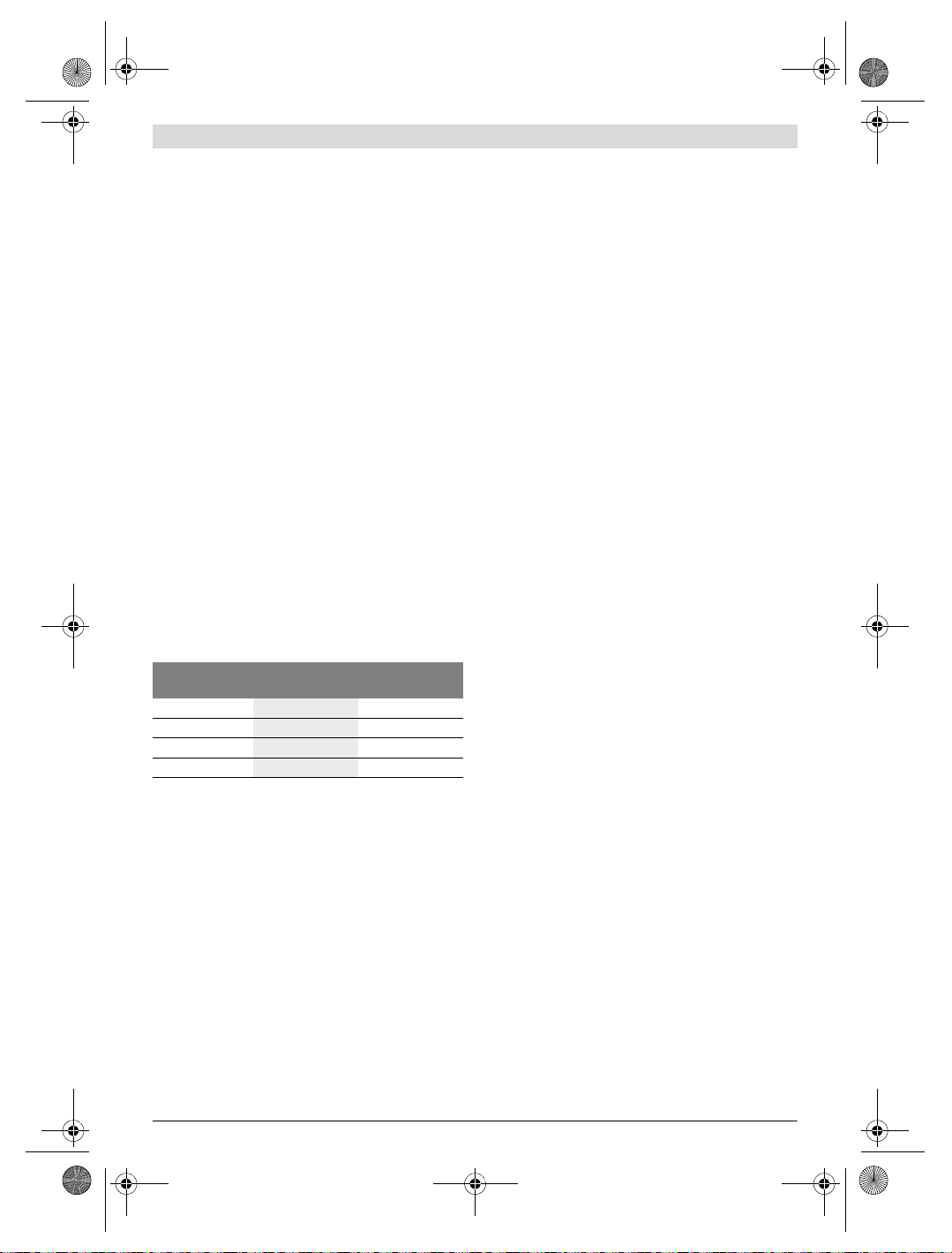
OBJ_BUCH-3136-002.book Page 24 Tuesday, August 22, 2017 6:26 PM
24 | English
Definitions
Infrared heat radiation
Infrared heat radiation is electromagnetic radiation emitted
by every body. The amount of radiation depends on the temperature and the emissivity degree of the body.
Emissivity Degree
The emissivity degree of an object depends on the material
and the structure of its surface. It states how much infrared
heat radiation the object emits compared to an ideal heat
emitter (black body, emissivity degree = 1).
Thermal Bridge
A thermal bridge is an object that undesirably transmits heat
outwards or inwards, therefore differing significantly from the
temperature of the rest of a wall or from the desired temperature of a wall.
As the surface temperature at thermal bridges is lower than in
the rest of the room, the risk of mould increases significantly
at these locations.
Reflected temperature/reflectivity of an object
The reflected temperature is the thermal radiation that is not
emitted by the object itself. Depending on the structure and
material, background radiation is reflected in the object to be
measured, therefore distorting the actual temperature result.
Distance from the object
The distance between the object being measured and the
measuring tool influences the captured area size per pixel.
You can capture increasingly large objects as the distance
from the object becomes greater.
Distance (m) Size of infrared
0.5
1
2
5
pixels (mm)
3 ~0.5 x 0.4
6 ~1 x 0.75
12 2.05 x 1.5
30 5.1 x 3.8
Infrared range
width x height (m)
TrackMyTools
The built-in Bluetooth® Low Energy Module enables you to
personalise and check the status of your measuring tool, as
well as transfer settings and data using Bluetooth® wireless
technology.
TrackMyTools Bluetooth® module power supply
The measuring tool is fitted with a button cell so that it can still
be detected by a mobile device using TrackMyTools without
having a battery pack 23 or batteries inserted.
You can find further information directly in the app from
Bosch.
Data Transmission
You can switch the TrackMyTools Bluetooth® module on and
off in the tool settings. It then emits a continuous signal.
The transmission interval of the module is eight seconds.
Depending on ambient conditions, up to three transmission
intervals may be required before the measuring tool is detected.
Note: Switch TrackMyTools off in areas where the transmission of radio waves is prohibited, for example on aeroplanes.
Registering and setting up the app/web-based
application
Be fore you can use Tra ckM yTo ols , yo u ne ed to reg ist er o nli ne.
To do this, open the website www.bosch-trackmytools.com
and register. After registration is complete, you will receive
your access information.
Download the app TrackMyTools from the relevant app store
(Apple App Store, Google Play Store) or access the web application at https://web.bosch-trackmytools.com, where you
can log in using your access details.
You can now create and manage your inventory using the
app/web-based application.
Note: First, complete the tutorial for the app/web-based application. This will provide you with a better overview of the
procedure for creating the inventory and using the software.
Maintenance and Service
Maintenance and Cleaning
Store and transport the measuring tool only in a suitable container such as the original packaging or the protective pouch
(accessory). Do not affix any stickers near to the infrared sensor on the measuring tool.
Keep the measuring tool clean at all times.
When cleaning, fluids should not penetrate into the measur-
ing tool.
Do not attempt to remove dirt from the sensor, camera or re-
ception lens using pointed objects, and do not wipe over the
camera and reception lens (risk of scratching).
If you would like your measuring tool to be recalibrated,
please contact a Bosch service centre (for addresses, see
section “After-sales Service and Application Service”).
If the event of a repair, send in the measuring tool in the original packaging or in the protective pouch (accessory).
The integrated button cell may only be removed for disposal
by qualified personnel. Opening the housing shell can destroy
the measuring tool. Unscrew the screws on the housing and
remove the housing shell in order to remove the button cell.
After-sales Service and Application Service
Our after-sales service responds to your questions concerning maintenance and repair of your product as well as spare
parts. Exploded views and information on spare parts can
also be found under:
www.bosch-pt.com
Bosch’s application service team will gladly answer questions
concerning our products and their accessories.
In all correspondence and spare parts orders, please always
include the 10-digit article number given on the nameplate of
the product.
1 609 92A 3RD | (22.8.17) Bosch Power Tools
OBJ_BUCH-3136-002.book Page 25 Tuesday, August 22, 2017 6:26 PM
Great Britain
Robert Bosch Ltd. (B.S.C.)
P.O. Box 98
Broadwater Park
North Orbital Road
Denham
Uxbridge
UB 9 5HJ
At www.bosch-pt.co.uk you can order spare parts or arrange
the collection of a product in need of servicing or repair.
Tel. Service: (0344) 7360109
E-Mail: boschservicecentre@bosch.com
Ireland
Origo Ltd.
Unit 23 Magna Drive
Magna Business Park
City West
Dublin 24
Tel. Service: (01) 4666700
Fax: (01) 4666888
Australia, New Zealand and Pacific Islands
Robert Bosch Australia Pty. Ltd.
Power Tools
Locked Bag 66
Clayton South VIC 3169
Customer Contact Center
Inside Australia:
Phone: (01300) 307044
Fax: (01300) 307045
Inside New Zealand:
Phone: (0800) 543353
Fax: (0800) 428570
Outside AU and NZ:
Phone: +61 3 95415555
www.bosch-pt.com.au
www.bosch-pt.co.nz
Supplier code ERAC000385
Republic of South Africa
Customer service
Hotline: (011) 6519600
Gauteng – BSC Service Centre
35 Roper Street, New Centre
Johannesburg
Tel.: (011) 4939375
Fax: (011) 4930126
E-Mail: bsctools@icon.co.za
KZN – BSC Service Centre
Unit E, Almar Centre
143 Crompton Street
Pinetown
Tel.: (031) 7012120
Fax: (031) 7012446
E-Mail: bsc.dur@za.bosch.com
Western Cape – BSC Service Centre
Democracy Way, Prosperity Park
Milnerton
Tel.: (021) 5512577
Fax: (021) 5513223
E-Mail: bsc@zsd.co.za
Bosch Headquarters
Midrand, Gauteng
Tel.: (011) 6519600
Fax: (011) 6519880
E-Mail: rbsa-hq.pts@za.bosch.com
Transport
The usable lithium-ion battery packs are subject to the Dangerous Goods Legislation requirements. The user can transport the battery packs by road without further requirements.
When being transported by third parties (e.g. via air transport
or forwarding agency), special requirements on packaging
and labelling must be observed. For preparation of the item
being shipped, consulting an expert for hazardous material is
required.
Dispatch battery packs only when the housing is undamaged.
Tape or mask off open contacts and pack up the battery pack
in s uch a m anner that i t can not mo ve aro und in the pa ckag ing.
Please also observe possibly more detailed national regulations.
Disposal
Only for EC countries:
According to the European Guideline 2012/19/EU, measuring tools that are no longer usable, and according to the European Guideline 2006/66/EC, defective or used battery
packs/batteries, must be collected separately and disposed
of in an environmentally correct manner.
Batteries no longer suitable for use can be directly returned at:
Great Britain
Robert Bosch Ltd. (B.S.C.)
P.O. Box 98
Broadwater Park
North Orbital Road
Denham
Uxbridge
UB 9 5HJ
At www.bosch-pt.co.uk you can order spare parts or arrange
the collection of a product in need of servicing or repair.
Tel. Service: (0344) 7360109
E-Mail: boschservicecentre@bosch.com
English | 25
Measuring tools, battery packs/batteries, accessories and packaging should be sorted for environmental-friendly recycling.
Do not dispose of measuring tools and batteries/rechargeable batteries into household waste!
Bosch Power Tools 1 609 92A 3RD | (22.8.17)
OBJ_BUCH-3136-002.book Page 26 Tuesday, August 22, 2017 6:26 PM
26 | Français
Battery packs/batteries:
Li-ion:
Please observe the instructions in section “Transport”,
page 25.
Subject to change without notice.
Français
Avertissements de sécurité
Prière de lire et de respecter l’ensemble des
instructions. Au cas où l’appareil de mesure
n’est pas utilisé conformément aux présentes
instructions, les dispositifs de protection intégrés risquent de ne pas fonctionner correctement. BIEN CONSERVER LES PRÉSENTES
INSTRUCTIONS.
Ne faire réparer l’appareil de mesure que par une per-
sonne qualifiée et seulement avec des pièces de rechange d’origine. Ceci permet d’assurer la sécurité de
l’appareil de mesure.
Ne pas faire fonctionner les appareils de mesure en at-
mosphère explosive, par exemple en présence de liquides inflammables, de gaz ou de poussières. L’appa-
reil de mesure produit des étincelles qui peuvent
enflammer les poussières ou les vapeurs.
Retirer l’accu ou les piles avant d’effectuer des travaux
sur l’appareil (p. ex. montage, opérations d’entretien,
etc.) ainsi que pour son transport ou son stockage.
Ne pas ouvrir l’accumulateur. ll y a risque de court-cir-
cuit.
Protéger l’accumulateur de toute source de
chaleur, comme par ex. l’exposition directe au
soleil, au feu, à l’eau et à l’humidité. Il y a risque
d’explosion.
Lorsqu’un accumulateur n’est pas utilisé, le maintenir à
l’écart de tout autre objet métallique, par exemple
trombones, pièces de monnaie, clés, clous, vis ou
autres objets de petite taille qui peuvent donner lieu à
une connexion d’une borne à une autre. Un court-circuit
entre les contacts d’accumulateur peut provoquer des brûlures ou un incendie.
En cas d’utilisation abusive, du liquide peut sortir de
l’accumulateur. Eviter tout contact. En cas de contact
accidentel, nettoyer à l’eau. Si la substance liquide
entre en contact avec les yeux, consulter un médecin.
La substance liquide qui s’échappe de l’accumulateur peut
entraîner des irritations de la peau ou causer des brûlures.
En cas d’endommagement et d’utilisation non
conforme de l’accumulateur, des vapeurs peuvent
s’échapper. Ventiler le lieu de travail et, en cas de malaises, consulter un médecin. Les vapeurs peuvent irriter
les voies respiratoires.
1 609 92A 3RD | (22.8.17) Bosch Power Tools
Ne recharger qu’avec le chargeur spécifié par le fabri-
cant. Un chargeur approprié à un type spécifique d’accu-
mulateur peut engendrer un risque d’incendie lorsqu’il est
utilisé avec d’autres accumulateurs.
N’utiliser l’accumulateur qu’avec votre appareil de me-
sure Bosch. Ceci protège l’accumulateur contre une sur-
charge dangereuse.
Les objets pointus (clou, tournevis, etc.) et les forces
extérieures exercées sur le boîtier risquent d’endommager l’accu. Il peut en résulter un court-circuit interne et
l’accu risque de s’enflammer, de dégager des fumées, d’exploser ou de surchauffer.
L’adaptateur de piles est uniquement destiné à une uti-
lisation sur les appareils de mesure Bosch prévus à cet
effet. Il n’est pas conçu pour être utilisé avec des outils
électroportatifs.
Sortez les piles de l’appareil de mesure au cas où l’ap-
pareil ne serait pas utilisé pendant une période prolongée. En cas de stockage prolongé, les piles peuvent se cor-
roder et se décharger.
Protégez l’appareil de mesure de l’humidité et de la
neige (surtout la partie caméra et lentille infrarouge). La
lentille de réception pourrait s’embuer et fausser ainsi les résultats de mesure. Un réglage erroné de l’appareil et certaines conditions atmosphériques défavorables risquent
également de fausser les mesures. Les objets peuvent être
représentés plus chauds ou plus froids qu’ils ne sont en réalité. Il y a alors risque de brûlure en cas de contact.
En présence d’écarts de température importants dans
une image thermique, il se peut que des températures
assez élevées soient représentées dans une couleur
pouvant être associée à des températures basses. Tout
contact avec une telle surface peut alors entraîner des brûlures !
L’appareil de mesure ne peut réaliser des mesures de
températures correctes que si le taux d’émissivité réglé et le taux d’émissivité réel de l’objet coïncident. Les
objets peuvent être représentés – en température et/ou en
couleur – plus chauds ou plus froids qu’ils ne son t en réalité, ce qui peut représenter un danger en cas de contact.
Attention ! En cas d’utilisation de l’appareil de mesure
en mode Bluetooth®, les ondes émises risquent de perturber le fonctionnement de certains appareils et installations ainsi que le fonctionnement des avions et des
appareils médicaux (par ex. stimulateurs cardiaques,
prothèses auditives). Les ondes émises peuvent aussi
avoir un effet nocif sur les personnes et les animaux qui
se trouvent à proximité immédiate de l’appareil. N’utilisez pas l’appareil de mesure en mode Bluetooth® à
proximité d’appareils médicaux, de stations-service,
d’usines chimiques et lorsque vous vous trouvez dans
des zones à risque d’explosion ou dans des zones de dynamitage. N’utilisez pas l’appareil de mesure en mode
Bluetooth® dans les avions. Evitez une utilisation pro-
longée de l’appareil très près du corps.
L’appareil de mesure est doté d’une interface radio.
Observez les restrictions d’utilisation valables localement, parex. dans les avions ou les hôpitaux.

OBJ_BUCH-3136-002.book Page 27 Tuesday, August 22, 2017 6:26 PM
Description et performances du
produit
Dépliez le volet sur lequel l’appareil de mesure est représenté
de manière graphique. Laissez le volet déplié pendant la lecture de la présente notice d’utilisation.
Le nom de marque Bluetooth® tout comme les logos sont
des marques déposées et la propriété de Bluetooth SIG,
Inc. Toute utilisation de cette marque/de ce logo par la Robert Bosch Power Tools GmbH se fait dans le cadre d’une
licence.
Utilisation conforme
Cette caméra thermique est conçue pour la mesure sans
contact de températures de surface.
L’image thermique affichée montre la répartition des températures dans la zone de détection de la lentille infrarouge. Les
écarts de température sont représentés par des différences
de couleur.
En cas d’utilisation correcte, la caméra thermique permet de
détecter sans contact des écarts de température sur des surfaces et des objets pour mettre en évidence des éléments/
composants défectueux et/ou des anomalies. Exemples
d’applications :
–Examen d’isolations thermiques (pour déceler des ponts
thermiques par ex.)
– Localisation de conduites d’eau de chauffage et d’eau
chaude (par ex. tuyaux de chauffage par le sol) dans les
sols et les murs
– Détection de composants électriques en surchauffe, par
ex. fusibles ou bornes
– Examen de pièces machine (pour déceler d’éventuelles sur-
chauffes dues à des roulements à billes défectueux par ex.)
L’appareil de mesure ne doit pas être utilisé pour mesurer la
température de personnes ou d’animaux ni à d’autres fins médicales.
L’appareil de mesure n’est pas conçu pour mesurer la température de surface de gaz ou de liquides.
Eléments de l’appareil
La numérotation des éléments de l’appareil se réfère à la représentation de l’appareil de mesure sur la page graphique.
1 Capuchon de protection de la caméra et du capteur infra-
rouge
2 Numéro de série
3 Cache de protection de la prise micro-USB
4 Prise micro-USB
5 Touche Flèche vers le haut
6 Touche Fonctions de mesure «Func»
7 Commutation automatique-gelé pour l’échelle de tempé-
8 Touche flèche vers la droite
9 Touche Marche/Arrêt
10 Touche Flèche vers le bas
11 Touche Mémoriser
12 Touche flèche vers la gauche
13 Touche Galerie / touche de fonction gauche
14 Ecran
15 Caméra visuelle
16 Capteur infrarouge
17 Touche Gel mesure / Poursuite mesure
18 Compartiment à accu
19 Bouton de déverrouillage accu / adaptateur de piles
20 Couvercle de l’adaptateur de piles *
21 Corps de l’adaptateur de piles *
22 Évidement du corps de l’adaptateur
23 Accu *
24 Câble micro-USB
25 Etui de protection *
* Les accessoires décrits ou illustrés ne sont pas tous compris dans
la fourniture.
Affichages
a Date/heure
b Fonction de mesure
c Taux d’émissivité
d Affichage de connexion Bluetooth®
e Affichage WiFi activé/désactivé
f Etat de charge
g Affichage température de surface maximale dans la zone
de mesure
h Échelle
i Affichage température de surface minimale dans la zone
de mesure
j Symbole blocage échelle
k Affichage point chaud (exemple)
l Réticule avec affichage de température
m Affichage point froid (exemple)
n Symbole Galerie
Français | 27
ratures / touche de fonction droite
Bosch Power Tools 1 609 92A 3RD | (22.8.17)
OBJ_BUCH-3136-002.book Page 28 Tuesday, August 22, 2017 6:26 PM
28 | Français
Caractéristiques techniques
Caméra thermique GTC 400 C
N° d’article
Résolution du capteur à infrarouge
Sensibilité thermique
Bande spectrale
Champ de vision (FOV)
Distance de focalisation
Mise au point
Plage de mesure de températures de surface
Précision de mesure (typique)
Température de surface
1)
–10…+10 °C
10…100 ° C
>+100°C
Type d’écran
Taille de l’affichage
Résolution d’écran
Format d’image
Images enregistrées à chaque mémorisation
1 image thermique (copie d’écran)
1 image réelle avec valeurs de température (métadonnées)
Capacité typique de la mémoire d’images (en nombre de photos)
Caméra visuelle intégrée
Piles (alcalines au manganèse)
4 x 1,5 V LR6 (AA) (avec adaptateur de piles)
Accumulateur (Lithium-ion)
Autonomie
– Piles (alcalines au manganèse)
– Accumulateur (Lithium-ion)
Prise USB
Alimentation en énergie du module Bluetooth® TrackMyTools
–Pile bouton
CR2450 (pile lithium de 3 V)
– Durée de vie de la pile env.
Bluetooth®
Bluetooth® 4.2 (faible consommation d’énergie)
Puissance d’émission maximale Bluetooth®
Bande de fréquence Bluetooth®
Connectivité sans fil
Puissance d’émission maximale WiFi
Plage de fréquences de fonctionnement WiFi
Poids suivant EPTA-Procedure 01:2014
Dimensions (longueur x largeur x hauteur)
Type de protection (à l’exception du compartiment à piles)
Le numéro de série 2 qui se trouve sur la plaque signalétique permet une identification précise de votre appareil.
1) À une température ambiante de 20 –23 °C et un taux d’émissivité > 0,999, distance de mesure minimale = 0,3 m, durée de fonctionnement > 5 min
2) performances réduites à des températures <0 °C
Caractéristiques techniques déterminées avec l’accu fourni avec l’appareil.
3 601 K83 1..
160 x 120
<50mK
8–14μm
53 x 43°
≥0,3m
–10…+400°C
320 x 240
10,8 V/12 V
60 Mois
3,2 mW
2,402 – 2,480 GHz
30 mW
2,400– 2,483 GHz
0,54 kg
233 x 95 x 63 mm
fixe
±3 ° C
±3 ° C
±3 %
TFT
3,5″
.jpg
500
2,0 h
5,0 h
1.1
WiFi
IP 53
1 609 92A 3RD | (22.8.17) Bosch Power Tools
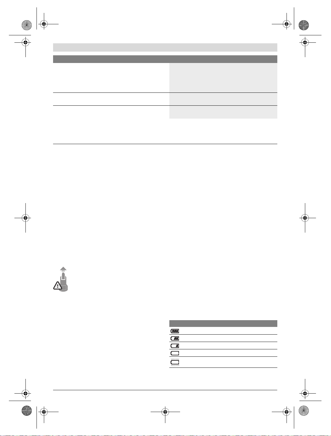
OBJ_BUCH-3136-002.book Page 29 Tuesday, August 22, 2017 6:26 PM
Français | 29
Caméra thermique GTC 400 C
Conditions ambiantes admissibles
– Température de charge
– Température de fonctionnement
2)
– Température de stockage
– Humidité d’air relative (sans condensation)
Accus recommandés
0…+45°C
–10…+45 °C
–20…+70 °C
20… 80 %
GBA 10,8 V
GBA 12 V
Chargeurs recommandés
AL 11.. CV
GAL 12.. CV
Le numéro de série 2 qui se trouve sur la plaque signalétique permet une identification précise de votre appareil.
1) À une température ambiante de 20 –23 °C et un taux d’émissivité > 0,999, distance de mesure minimale = 0,3 m, durée de fonctionnement > 5 min
2) performances réduites à des températures <0 °C
Caractéristiques techniques déterminées avec l’accu fourni avec l’appareil.
Montage
Alimentation en énergie
L’appareil de mesure peut être alimenté soit par des piles
usuelles du commerce (piles AA type LR6 ou équivalent), soit
par un accu Lithium-ion Bosch.
Fonctionnement avec adaptateur de batterie (extractible) (voir figure A)
Les piles doivent être insérées dans l’adaptateur de piles.
L’adaptateur de piles est uniquement destiné à une uti-
lisation sur les appareils de mesure Bosch prévus à cet
effet. Il n’est pas conçu pour être utilisé avec des outils
électroportatifs.
Pour insérer les piles, poussez le corps de l’adaptateur de
batterie 21 dans le compartiment à accu 18. Insérez les piles
dans le corps comme représenté sur l’illustration du couvercle 20. Glissez le couvercle au-dessus du corps jusqu’à ce
qu’il s’enclenche de manière audible sans dépasser de la poignée de l’appareil de mesure.
Pour retirer les piles, pressez les pattes de déverrouillage 19 du couvercle 20 et sortez le couvercle. Veillez ce faisant à ce que les piles ne
tombent pas. Tenez pour cela l’appareil de mesure
avec le compartiment à accu 18 orienté vers le
haut. Retirez les piles. Pour extraire le corps de
l’adaptateur 21 du compartiment d’accu 18, glissez un doigt
dans l’évidement 22 du corps et sortez le corps de l’appareil
de mesure en exerçant une légère pression sur la paroi latérale (voir figure B).
Note : Pour retirer l’accu, n’utilisez pas d’outil (tournevis ou
autre) car le corps de l’adaptateur risquerait alors d’être détérioré.
Remplacez toujours toutes les piles en même temps. N’utilisez que des piles de la même marque avec la même capacité.
Sortez les piles de l’appareil de mesure au cas où l’ap-
pareil ne serait pas utilisé pendant une période prolongée. En cas de stockage prolongé, les piles peuvent se cor-
roder et se décharger.
Utilisation avec accumulateur (voir figure C)
Note : L’utilisation d’accumulateurs non appropriés pour
votre appareil de mesure peut entraîner des dysfonctionnements ou endommager l’appareil de mesure.
Note : L’accumulateur fourni avec l’appareil est en état de
charge faible. Afin de garantir la puissance complète de l’accumulateur, chargez-le complètement dans le chargeur avant
la première mise en service.
N’utilisez que les chargeurs indiqués dans les Caracté-
ristiques techniques. Ces chargeurs sont les seuls à être
adaptés à l’accu Lithium-Ion de votre appareil de mesure.
L’accumulateur à ions lithium peut être rechargé à tout moment, sans que sa durée de vie n’en soit réduite. Le fait d’interrompre le processus de charge n’endommage pas l’accumulateur.
Après une désactivation automatique de l’appareil de
mesure, ne pas essayer de le réactiver en actionnant
l’interrupteur Marche/Arrêt. Ceci pourrait endommager
l’accu.
Pour insérer l’accu 23 chargé, glissez-le dans le compartiment à accu 18 jusqu’à ce qu’il s’enclenche de manière
audible sans dépasser de la poignée de l’appareil de mesure.
Pour extraire l’accu 23, pressez les pattes de déverrouillage
19 et retirez l’accu du compartiment à accu 18. Ne forcez
pas.
Voyant lumineux indiquant l’état de charge
Le voyant lumineux f de l’écran indique le niveau de charge
des piles ou de l’accu 23.
Affichage Capacité
>2/3
≤2/3
≤1/3
≤10%
Remplacez les piles ou l’accu
Bosch Power Tools 1 609 92A 3RD | (22.8.17)
OBJ_BUCH-3136-002.book Page 30 Tuesday, August 22, 2017 6:26 PM
30 | Français
Fonctionnement
Protégez l’appareil de mesure contre l’humidité, ne
l’exposez pas directement aux rayons du soleil.
N’exposez pas l’appareil de mesure à des températures
extrêmes ou de forts changements de température. Ne
le stockez pas trop longtemps dans une voiture par ex. S’il
est exposé à d’importants changements de température,
laissez-le revenir à la température ambiante avant de le remettre en marche. Des températures extrêmes ou de forts
changements de température peuvent réduire la précision
de l’appareil de mesure.
Laissez l’appareil de mesure prendre la température
ambiante avant de le mettre en marche. En cas de fortes
fluctuations de température ou de conditions ambiantes
fortement changeantes, la précision de mesure risque
d’être altérée jusqu’à ce que l’appareil de mesure retrouve
un équilibre thermique.
Evitez les chocs violents et évitez de faire tomber l’ap-
pareil de mesure. Après avoir soumis l’appareil de mesure
à des actions extérieures particulières ou en cas de détection d’un fonctionnement anormal de sa part, prière de
faire contrôler l’appareil de mesure dans un point de service après-vente Bosch.
Mise en service
Mise en marche/arrêt
Pour effectuer une mesure, soulevez le couvercle 1. Veillez
lors de l’utilisation de l’appareil à ce que le capteur infrarouge ne soit pas masqué ou partiellement recouvert.
Pour mettre en marche l’appareil de mesure, actionnez la
touche Marche/Arrêt 9. Il apparaît sur l’écran 14 une séquence de démarrage. Au terme de la séquence de démarrage, l’appareil de mesure se met aussitôt à mesurer et continue à mesurer jusqu’à ce qu’il soit éteint.
Note : Lors des premières minutes, il se peut que l’appareil
de mesure effectue plusieurs autocalibrages du fait que le
capteur ne se trouve pas encore à la température ambiante.
Les recalibrages permettent une mesure plus précise. Pendant les calibrages, l’image thermique se fige brièvement.
Pour arrêter l’appareil de mesure, actionnez à nouveau la
touche Marche/Arrêt. Avant de s’éteindre, l’appareil de mesure enregistre tous les réglages. Refermez le couvercle 1
pour permettre un transport de l’appareil de mesure en toute
sécurité.
Vous pouvez sélectionner dans le menu de réglage si l’appareil de mesure doit s’éteindre automatiquement et au bout de
combien de temps (voir « Délai d’arrêt », page 33).
Quand l’accu ou l’appareil de mesure se trouve en dehors de
la plage de températures de service indiqué dans les Caractéristiques techniques, l’appareil de mesure s’éteint automatiquement après un court avertissement (voir « Défaut –
Causes et remèdes », page 34). Attendez que la température
de l’appareil revienne à la température ambiante et remettezle en marche.
Pour économiser l’énergie, ne mettez en marche l’appareil de
mesure qu’au moment de son utilisation.
Préparation des prises de mesure
Régler l’émissivité pour des mesures de température de
surface
L’émissivité d’un objet dépend du matériau et de sa structure
de surface. Elle indique si un objet (comparé à d’autres objets
dont la température est la même) émet beaucoup ou peu de
rayonnement infrarouge.
Pour déterminer la température de surface, l’appareil mesure
le rayonnement thermique infrarouge naturel émis par l’objet
ciblé. Pour des mesures correctes, il convient de contrôler et
si nécessaire d’adapter à chaque mesure le taux d’émissivité
réglé sur l’appareil de mesure, pour être certain qu’il correspond bien à l’objet à mesurer.
Vous pouvez sélectionner l’un des taux d’émissivité préréglés
ou bien entrer une valeur numérique exacte. Le taux d’émissivit é se r ègle dans l e men u «Mesure»>« Taux d’émissivité »
(voir page 32).
L’appareil de mesure ne peut réaliser des mesures de
températures correctes que si le taux d’émissivité réglé et le taux d’émissivité réel de l’objet coïncident.
Les différences de couleur visibles sur l’image peuvent résulter de différences de température et/ou de différences de
taux d’émissivité. En cas de fortes variations du taux d’émissivité, les écarts de température affichés peuvent différer nettement des écarts de température réels.
Si plusieurs objets ayant une structure différente ou constitués d’un matériau différent se trouvent dans la zone de mesure, les températures affichées ne sont valables que pour les
objets dont le taux d’émissivité coïncide avec le taux d’émissivité réglé. Pour tous les autres objets (objets avec d’autres
taux d’émissivité), les écarts de température affichés peuvent
servir à établir des comparaisons et des relations entre les
températures.
Matériau Taux d’émissivité
Béton 0,93
Crépi/mortier 0,93
Brique 0,93
Carton bitumé 0,93
Peinture de radiateur 0,93
Bois 0,91
Linoléum 0,88
Papier 0,89
Indications spécifiques aux conditions de mesure
Les surfaces brillantes ou fortement réfléchissantes (p. ex.
carreaux brillants ou métaux à nu) peuvent fausser ou altérer
les résultats de mesure affichés. En cas de besoin, collez sur
la surface de mesure du ruban adhésif mat foncé à bonne
conductivité thermique. Attendez que le ruban adhésif ait pris
la température de la surface.
Dans le cas de surfaces réfléchissantes, prenez soin de choisir un angle de mesure favorable, afin que le rayonnement
thermique réfléchi par les autres objets environnants ne
fausse pas la mesure. Lors de mesures effectuées par l’avant,
(valeur indicative 0 ° C… 100 ° C)
1 609 92A 3RD | (22.8.17) Bosch Power Tools
Loading…
FAQ: Types of Manuals and Their Contents
Bosch GTC 400 C Manuals come in various types, each serving a specific purpose to help users effectively operate and maintain their devices. Here are the common types of Bosch GTC 400 C User Guides and the information they typically include:
- User Manuals: Provide comprehensive instructions on how to use the device, including setup, features, and operation. They often include troubleshooting tips, safety information, and maintenance guidelines.
- Service Instructions: Designed for technicians and repair professionals, these manuals offer detailed information on diagnosing and repairing issues with the device. They include schematics, parts lists, and step-by-step repair procedures.
- Installation Guides: Focus on the installation process of the device, providing detailed instructions and diagrams for proper setup. They are essential for ensuring the device is installed correctly and safely.
- Maintenance Manuals: Provide guidance on routine maintenance tasks to keep the device in optimal condition. They cover cleaning procedures, part replacements, and regular servicing tips.
- Quick Start Guides: Offer a concise overview of the essential steps needed to get the device up and running quickly. They are ideal for users who need immediate assistance with basic setup and operation.
Each type of Bosch GTC 400 C instruction is designed to address specific needs, ensuring users have the necessary information to use, maintain, and repair their devices effectively.
Related Instructions for Bosch GTC 400 C:
1
GBH 5-40 DCE Professional
252
361
80
3
MMBM1 Series
Instruction manual Bosch MMBM1 Series Guide (Instruction manual), @JH6KBE
53
1049
158
7
Evolution B20CS50SN
79
963
232
9
TCG4104GB
Instruction manual PDF Manual (@2U5796), Bosch TCG4104GB Grill (Tuesday 04-02-2025)
20
1134
182
10
B22CS Series
80
1395
349
Thermal cameras Devices by Other Brands:
|
Axis Q1910 Installation Manual Q1910 Installation manual — H48Q58 ENGLISH 21 Nov 2024 | 96 |
|
|
HeatSeeker 160 Instruction Manual #26DQ57: 160 Thermal cameras Instruction manual #61-846 & 61-848 30 Apr 2025 | 27 |
|
|
Autel MaxiIRT IR100 Manual User Guide: Autel MaxiIRT IR100 (16MT67, Upd.Sun 12.2024) i 22 Dec 2024 | 32 |
|
|
Metek LAND LWIR Installation Manual PDF User Guide (@3FB1PV), Metek LAND LWIR Thermal cameras (04/05/2025) Long Wavelength Infrared Thermal Imaging Camera 04 May 2025 | 48 |
Categories:
Ice Maker
Rotational laser level
Headsets
Utility Vehicle
Relays
Induction cooktop
- June 5, 2024
- Bosch
Table of Contents
- General Safety Rules
- FCC Caution
- Features
- Technical Data
- Definitions
- Preparation
- Operation
- Functions
- Maintenance and Service
- Troubleshooting – Causes and Corrective Measures
- References
- Read User Manual Online (PDF format)
- Download This Manual (PDF format)
GTC 400C THERMO CAMERA
Instruction Manual
Operating/Safety Instructions
Call Toll-Free for Consumer Information & Service Locations
1-877-BOSCH99 (1-877-267-2499)
www.boschtools.com


Safety Symbols
The definitions below describe the level of severity for each signal word.
Please read the manual and pay attention to these symbols.
| This is the safety alert symbol. It is used to alert you to potential
personal injury hazards. Obey all safety messages that follow this symbol to
avoid possible injury or death.
—|—
| Read manual symbol – Alerts user to read manual.
WARNING
| WARNING indicates a hazardous situation that, if not avoided, could result
in death or serious injury.
| This symbol designates that this thermal camera tool complies with Part 15
of the FCC Rules.
General Safety Rules
WARNING Read all safety warnings, instructions, illustrations, and
specifications provided with this tool. Failure to follow all instructions
listed below may result in electric shock, fire, and/or serious injury.
SAVE ALL WARNINGS AND INSTRUCTIONS FOR FUTURE REFERENCE
The term “tool” in the warnings refers to your mains-operated (corded) tool or
battery-operated (cordless) tool.
Use and care
Use the correct tool for your application. The correct tool will do the
job better and safer.
Protect the tool, particularly the area around the camera and infrared lens,
against moisture and snow. The reception lens could fog up and distort the
measurements. Incorrect settings on the tool and other atmospheric influences
may make the measurements inaccurate. Objects could be depicted as hotter or
colder, which may present a danger if touched.
High-temperature differences in a thermal image may cause even high
temperatures to be shown in a color associated with low temperatures. Coming
into contact with such an area may cause burns.
Temperature measurements will only be correct if the emissivity setting and
the emissivity of the object match. Objects could be depicted hotter or colder
in temperature and/or color, which may present a danger if touched.
Do not use the tool if the switch does not turn on and off. Any tool that
cannot be controlled with the switch is dangerous and must be repaired.
Store idle tools out of the reach of children and do not allow persons
unfamiliar with the tool or these instructions to operate the tool. Tools are
dangerous in the hands of untrained users.
Maintain tools. Check for misalignment or binding of moving parts, breakage of
parts, and any other condition that may affect the operation. If damaged, the
tool is repaired before use. Many accidents are caused by poorly maintained
tools.
Use the tool, accessories, etc., in accordance with these instructions and in
the manner intended for the particular type of tool, taking into account the
working conditions and the work to be performed. Use of the tool for
operations different from those intended could result in a hazardous
situation.
Battery tool use and care
Recharge only with the charger specified by the manufacturer. A charger that
is suitable for one type of battery pack may create a risk of fire when used
with another battery pack.
Use tool only with specifically designated battery packs. The use of any other
battery packs may create a risk of injury and fire.
When the battery pack is not in use, keep it away from other metal objects
like paper clips, coins, keys, nails, screws, or other small metal objects
that can make a connection from one terminal to another. Shorting the battery
terminals together may cause burns or a fire.
Under abusive conditions, liquid may be ejected from the battery; avoid
contact. If contact accidentally occurs, flush with water. If liquid contacts
the eyes, additionally seek medical help. Liquid ejected from the battery may
cause irritation or burns.
Do not use a battery pack or tool that is damaged or modified. Damaged or
modified batteries may exhibit unpredictable behavior resulting in fire,
EXPLOSION, or risk of injury.
Do not expose a battery pack or tool to fire or excessive temperature.
Exposure to fire or temperature above 265 °F (130 °C) may cause an explosion.
Follow all charging instructions and do not charge the battery pack or tool
outside the temperature range specified in the instructions. Charging
improperly or at temperatures outside the specified range may damage the
BATTERY and increase the risk of fire.
Disconnect the battery pack from the tool before making any adjustments,
changing accessories, or storing the tool. Such preventive safety measures
reduce the risk of starting the tool accidentally.
Do not modify or attempt to repair the tool or the battery pack except as
indicated in the instructions for use and care.
Service
Have your tool serviced by a qualified repair person using only identical
replacement parts. This will ensure that the safety of the tool is maintained.
Develop a periodic maintenance schedule for tools. When cleaning a tool be
careful not to disassemble any portion of the tool since internal wires may be
misplaced or pinched or may be improperly mounted. Certain cleaning agents
such as gasoline, carbon tetrachloride, ammonia, etc. may damage plastic
parts.
Electrical safety
WARNING Batteries can explode or leak, and cause injury or fire. To reduce
this risk, always follow all instructions and warnings on the battery label
and package.
DO NOT expose the tool and battery to rain or wet conditions. Water entering
tools will increase the risk of fire and personal injury.
DO NOT short any battery terminals.
DO NOT mix battery chemistries.
Dispose of or recycle batteries per local code.
DO NOT dispose of batteries in a fire.
Keep batteries out of reach of children.
Remove batteries if the device will not be used for several months. Remove the
batteries from the tool when not using it for extended periods. When stored
for extended periods, the batteries can corrode and self-discharge.
The tool is equipped with a radio interface. Local operating restrictions,
e.g. in airplanes or hospitals, are to be observed.
Prevent unintentional starting. Ensure the switch is in the off-position
before inserting batteries. An accidental energizing tool that has the switch
on invites accidents.
FCC Caution
The manufacturer is not responsible for radio interference caused by
unauthorized modifications to this equipment. Such modifications could void
the user’s authority to operate the equipment.
This device complies with Part 15 of the FCC Rules. Operation is subject to
the following two conditions:
- This device may not cause harmful interference, and
- This device must accept any interference received, including interference that may cause undesired operation.
NOTE! This equipment has been tested and found to comply with the limits
for Class B digital devices, pursuant to Part 15 of the FCC rules. These
limits are designed to protect reasonably against harmful interference in a
residential installation. This equipment generates uses and can radiate radio
frequency energy and, if not installed and used in accordance with the
instructions, may cause harmful interference to radio communications. To
comply with FCC’s RF radiation exposure limits for general
population/uncontrolled exposure, this device must not collect or operate in
conjunction with any other antenna or transmitter. However, there is no
guarantee that interference will not occur in a particular installation.
Suppose this equipment does cause harmful interference to radio or television
reception, which can be determined by turning the equipment off. In that case,
the user is encouraged to try to correct the interference by one or more of
the following measures:
- Reorient or relocate the receiving antenna.
- Increase the separation between the equipment and receiver.
- Connect the equipment into an outlet on a circuit different from that to which the receiver is connected.
- Consult the dealer or an experienced radio/TV technician for help.
“Exposure to Radio Frequency (RF) Signals: The wireless device is a radio
transmitter and receiver. It is designed and manufactured not to exceed the
emission limit for exposure to radio frequency (RF) energy set by the Ministry
of Health (Canada), Safety Code 6. These limits are part of comprehensive
guidelines and establish permitted levels of RF energy for the general
population.
To comply with FCC’s RF radiation exposure limits for general
population/uncontrolled exposure, this device must not be collocated or
operating in conjunction with any other antenna or transmitter.
Industry Canada (IC)
This device complies with Industry Canada’s license-exempt RSS. Operation
is subject to the following two conditions:
- This device may not cause interference; and
- This device must accept any interference, including interference that may cause undesired operation of the device.
Intended Use
This thermal imaging camera is designed for the contactless measurement of
surface temperatures.
The displayed thermal image shows the temperature distribution of the area
captured by the infrared lens and therefore enables temperature deviations to
be depicted in different colors.
When used correctly, this makes it possible to examine areas and objects in a
contactless manner for temperature differences and discrepancies in order to
make components and/or any weaknesses visible, including:
- Thermal insulation and other types of insulation (e.g. locating thermal bridges)
- Active heating and hot water pipes (e.g. underfloor heating) on floors and walls
- Overheated electrical components (e.g. fuses or terminals)
- Machine parts (e.g. overheating due to faulty ball bearings)
The tool must not be used for temperature measurement on persons and animals
or for other medical purposes.
The tool is not suitable for surface temperature measurement of gases or
liquids.
Features
The numbering of the product features shown refers to the illustration of the
tool on the graphic page.
1 Protective cap for visual camera and infrared sensor
2 Serial number
3 Cover, micro USB port
4 Micro USB port
5 Up arrow button [ ] 6 Measuring functions button [Func]| 7 Switching
temperature scale between automatic and fixed/right-hand function button
8 Right-hand arrow button [▶] 9 On/Off button [ ] 10 Down arrow button [ ] 11
Save button
12 Left-hand arrow button [◀] 13 Gallery button/left-hand function button| 14
Display
15 Visual camera
16 Infrared sensor area
17 Freeze measurement/continue
measuring button
18 Battery port
19 Release button for battery pack
20 Battery pack
21 Micro USB cable
22 Protective pouch
—|—|—
Display Elements
a Date/time
b Measuring function
c Emissivity display
d WiFi switched on/off indicator
e Charge-control indicator
f Display of maximum surface temperature in the measurement range
g Scale| h Display of minimum surface temperature in the measurement range
I Scale lock symbol
j Hotspot display (example)
k Crosshairs with temperature display
l Coldspot display (example)
m Gallery symbol
—|—
*The accessories illustrated or described are not included as standard delivery.
Technical Data
| Thermal imaging camera | GTC 400 C |
|---|---|
| Article number | 3 601 K83 1 |
| Resolution of infrared sensor | 160 x 120 |
| Thermal sensitivity | <50mK |
| Spectral range | 8–14 μm |
| Field of view (FOV) | 53 x 43° |
| Focus distance | ≥1 ft (≥0.3m) |
| Focus | Fixed |
| Surface temperature measurement range | 14…+752 °F (–10…+400 °C) |
Measuring accuracy (typical) Surface temperature¹
–10…+10 °C
10…100 °C
+100 °C| 5.4 °F (3 °C)
5.4 °F (3 °C)
3 %
Display type| TFT
Display size| 3.5”
Display resolution| 320 x 240
Image format| .jpg
Images saved per saving process| 1 x thermal image (screenshot)
1 x real visual image incl. temperature values (metadata)
Number of images in the internal image memory (typical)| 500
Integrated visual camera| •
Battery / Charger list
–Rechargeable Batteries (Bosch 10.8 V/12 V – Max lithium-ion pack)
–Chargers| BAT414 2.0 Ah, BAT420 4.0 Ah
GBA12V30 3.0 Ah, GBA12V60 6.0 Ah
BC330, BC430
GAX1218V-30, GAL 12V-20
Battery life
10.8 V/12 V – Max| 5.0 h
USB port| 1.1
Wireless connectivity| WiFi
Max. WiFi transmission power| 30mW
WiFi operating frequency range| 2.400–2.483 GHz
Weight according to EPTA-Procedure 01:2014| 0.54 kg
Dimensions (length x width x height)| 9.2” x 3.7” x 2.5” (233 x 95 x 63 mm)
Degree of protection (excluding battery compartment)| IP 53
Permitted environmental conditions
– Charging temperature
– Operating temperature ²)
– Storage temperature
– Relative humidity (non-condensing)| 32….+113 °F (0…+45 °C)
14….+113 °F (–10…+45 °C)
-4….+158 °F (–20…+70 °C)
20… 80 %
The tool can be clearly identified with serial number 2 on the type plate.
- at an ambient temperature of 20–23 °C and emissivity of >0.999, measuring distance: 0.3m, operating time: >5 min.
- limited performance at temperatures <0 °C.
Technical data determined with battery from the delivery scope.
Definitions
Infrared heat radiation
Infrared heat radiation is electromagnetic radiation emitted by everybody. The
amount of radiation depends on the temperature and the emissivity degree of
the body.
Emissivity Degree
The emissivity degree of an object depends on the material and the structure
of its surface. It states how much-infrared heat radiation the object emits
compared to an ideal heat emitter (black body, emissivity degree = 1).
Thermal Bridge
A thermal bridge is an object that undesirably transmits heat outwards or
inwards, therefore differing significantly from the temperature of the rest of
a wall or from the desired temperature of a wall.
As the surface temperature at thermal bridges is lower than in the rest of the
room, the risk of mold increases significantly at these locations.
Reflected temperature/reflectivity of an object
The reflected temperature is the thermal radiation that is not emitted by the
object itself. Depending on the structure and material, background radiation
is reflected in the object to be measured, therefore distorting the actual
temperature result.
Distance from the object
The distance between the object being measured and the measuring tool
influences the captured area size per pixel. You can capture increasingly
large objects as the distance from the object becomes greater.
Distance (m)| Size of infrared pixels (mm)| Infrared range width
x height (m)
—|—|—
0.5| 3| –0.5 x 0.4
1| 6| –1 x 0.75
2| 12| 2.05 x 1.5
5| 30| 5.1 x 3.8
Preparation
Power Supply
The tool can be operated using a Bosch Li-ion rechargeable battery.
Operation with Battery Pack (see figure C)
WARNING Use only Bosch rechargeable lithium-ion battery packs listed in
the technical data section of this manual. The use of other battery packs may
increase the risk of fire, personal injury, and property damage.
WARNING Remove the batteries from the tool when not using it for extended
periods. When stored for extended periods, the batteries can corrode and self-
discharge.
Note: The battery pack is supplied partially charged. To ensure the full
capacity of the battery pack, completely charge the battery pack in the
battery charger before using it for the first time.
WARNING Use only Bosch chargers listed in the technical data section of
this manual. Use of other chargers may increase the risk of fire, personal
injury, and property damage.
The lithium-ion battery pack can be charged at any time without reducing its
service life. Interrupting the charging procedure does not damage the battery
pack.
The lithium-ion battery is protected against deep discharge by the Electronic
Cell Protection (ECP). A protective circuit switches the laser level off when
the battery is drained.
- Following the automatic shut-off of the tool, do not continue to press the On/Off button. The battery can be damaged.
To insert the charged battery pack 20, slide it into the battery port
18 until you feel it lock into position. Do not use force.
To remove the battery pack 20, press the unlocking buttons 19 and
pull the battery pack out of the battery port 18. Do not use force.
Battery Status Indicator
The battery status indicator e on the display shows the charging state of the
batteries or battery pack 20.
| Indication | Capacity |
|---|---|
| >2/3 | |
| ≤2/3 | |
| ≤1/3 | |
| ≤10% | |
| Changing the Batteries or Battery Pack |
Operation
- Protect the measuring tool against moisture and direct sunlight.
- Do not subject the measuring tool to extreme temperatures or variations in temperature. As an example, do not leave it in vehicles for a long time. In case of large variations in temperature, allow the measuring tool to adjust to the ambient temperature before putting it into operation. In case of extreme temperatures or variations in temperature, the accuracy of the measuring tool can be impaired.
- Make sure that the tool is correctly acclimatized. In the event of severe temperature fluctuations or environmental conditions which vary to a large degree, the measurement accuracy of the measuring tool may be impaired until it is fully acclimatized again.
- Avoid hard knocks on the tool or dropping it. After severe external influences and in the event of abnormalities in the functionality, you should have the measuring tool checked by an authorized Bosch after-sales service agent.
Initial Operation
Switching On and Off
To take a measurement, fold the protective cap 1 upwards. Make sure that the
infrared measuring area is not closed off or covered while working.
To switch on the tool, press the On/Off button 9. A start sequence will appear
in display 14. After the start sequence, the measuring tool will immediately
begin to measure and will measure continuously until it is switched off.
Note: In the first few minutes, the measuring tool may self-calibrate
several times, as the sensor temperature and ambient temperature have not yet
been brought into line. Performing calibration again enables precise
measurement. The thermal image freezes briefly during calibration.
To switch off the tool, press the On/Off button again. The measuring tool
saves all settings and then switches itself off. Close the protective cap 1 to
transport the measuring tool safely.
In the “Settings” menu, you can choose whether and after how much time the
measuring tool automatically switches off (see “Switch-off time”, page 15).
If the battery or the measuring tool is not within the operating temperature
range stated in the Technical Data, the measuring tool will shut down
automatically after a brief warning (see “Troubleshooting – Causes and
Corrective Measures”, page 17). Allow the measuring tool to reach the correct
temperature and then switch it back on.
To save energy, only switch the measuring tool on when you are using it.
Preparing for Measurement
Setting the Emissivity Degree for Surfacetemperature Measurements
The emissivity degree of an object depends on the material and the structure
of its surface. It indicates whether an object (in comparison with other
objects with the same temperature) emits much or little infrared heat
radiation.
To determine the surface temperature, the tool performs contactless
measurement of the natural infrared thermal radiation emitted by the object at
which the tool is aimed. To ensure correct measurement, the emissivity setting
on the measuring tool must be checked before every measurement and adapted to
the measuring object if necessary.
You can select one of the preset emissivity levels or enter an exact numerical
value. Adjust the required emissivity using the **“Measurement”
“Emissivity” menu (see page 14).
WARNING** Temperature measurements will only be correct if the emissivity
setting and the emissivity of the object match.
Differences in color may be caused by different temperatures and/or different
emissivity levels. If the emissivity levels are very different, the depicted
temperature differences may differ considerably from the actual temperature
differences.
If there are multiple objects made of different materials or that have
different structures in the measurement range, the displayed temperature
values are only conclusive for the objects that match the emissivity setting.
For all other objects (with different emissivity levels), the displayed color
differences can be used as an indication of temperature relationships.
| Material | Emissivity 32 ºF to 212 ºF (0 ºC to 100 ºC) |
|---|---|
| Concrete | 0.93 |
| Plaster/mortar | 0.93 |
| Roofing tiles | 0.93 |
| Roofing felt | 0.93 |
| Radiator paint | 0.93 |
| Wood | 0.91 |
| Linoleum | 0.88 |
| Paper | 0.89 |
Notes on the Measuring Conditions
Highly reflective or shiny surfaces (e.g. shiny tiles or polished metals) may
distort or impair the results shown. If necessary, mask the surface to be
measured with a dark, matt adhesive tape that conducts heat well. Allow the
tape to acclimatize briefly on the surface.
Make sure that a favorable measuring angle is used on reflective surfaces in
order to ensure that the thermal radiation reflected by other objects does not
distort the result. For example, the reflection of your own body heat may
interfere with the measurement when measuring head-on from a perpendicular
position. On a level surface, the outline and temperature of your body could
therefore be displayed (reflected value), and these values do not correspond
to the actual temperature of the measured surface (emitted value or real value
of the surface). Measuring through transparent materials (e.g. glass or
transparent plastics) is fundamentally not possible.
The accuracy and reliability of the measuring results increase with better and
more stable measuring conditions.
Infrared temperature measurement is impaired by smoke, vapor/ high air
humidity, or dusty air. Information for achieving improved measurement
accuracy:
- Get as close as possible to the measuring object to minimize interfering factors between you and the surface to be measured.
- Ventilate indoor areas prior to measurement, especially when the air is contaminated or extremely steamy. After ventilating, allow the room to acclimatize for a while until the usual temperature has been reached again.
Assigning temperatures on the basis of the scale
A scale is shown on the right-hand side of the display. The values at the top
and bottom end are oriented to the maximum and minimum temperature recorded in
the thermal image. Colors are assigned to temperature values with a uniform
distribution in the image (linearly).
Different shades can therefore be used to assign temperatures within these two
limit values. For example, a temperature that is exactly between the maximum
and minimum value can be assigned to the center color range of the scale.
To determine the temperature of a specific area, move the measuring tool so
that the crosshairs with temperature display l are aimed at the required point
or area.
In the automatic setting, the color spectrum of the scale is always
distributed linearly (= uniformly) across the entire measurement range between
the maximum and minimum temperatures.
The thermal imaging camera displays all measured temperatures in the
measurement range in relation to one another. If heat is displayed as blue in
the color palette in an area, for example in a color representation, this
means that the blue areas are among the colder measured values in the current
measurement range. However, these areas may be in a temperature range that
could cause injuries in certain circumstances. You should therefore always
note the temperatures displayed on the scale or at the crosshairs themselves.
Functions
Adjusting the color display
Depending on the measurement conditions, different color palettes can make it
easier to analyze the thermal image and show objects or circumstances more
clearly in the display. This does not affect the measured temperatures. Only
the way in which the temperature values are shown changes.
To change the color palette, remain in measuring mode and press the right-hand
8 or left-hand 12 arrow button.
Superimposition of thermal image and real image
For improved orientation (= local assignment of the thermal image displayed),
with matched temperature ranges, a visual real image can additionally be
inserted.
Note: The superimposition of the real image and thermal image is accurate
at a distance of 1.08 ft (0.55 m). If the tool is closer to or further away
from the object being measured, this may result in misalignment of the real
image and thermal image.
The thermal imaging camera offers you the following options:
-
Complete infrared image
Only the thermal image is displayed. -
Image in image
The thermal image displayed is cropped and the surrounding area is shown as a
real image. This setting improves the local assignment of the measurement
range. -
Transparency
The thermal image displayed is placed on top of the real image in such a
way that it is slightly transparent. This enables improved detection of
objects.
You can adjust the setting by pressing the up 5 or down 10 arrow buttons.
Fixing the scale
The color distribution in the thermal image is adjusted automatically but can
be fixed by pressing the right-hand function button 7. This enables a
comparison to be made between thermal images taken under different temperature
conditions (e.g. when checking several rooms for thermal bridges).
To switch the scale back to automatic, press the right-hand function button 7
again. The temperatures are now dynamic again and adapt to the measured
minimum and maximum values.
Measuring functions
To call up further functions which may be helpful for the display, press the
“Func” button 6. Use the right-hand/left-hand buttons to navigate through the
displayed options to select a function. Select a function and press the
“Func” button 6 again.
The following measuring functions are available:
-
“Automatic”
Colors are distributed automatically in the thermal image -
“Heat detector”
Only the warmer temperatures in the measurement range are displayed as a
thermal image in this measuring function.
The area outside these warmer temperatures is displayed in greyscale as a real
image so that colored objects are not wrongly associated with temperatures
(e.g. red cable in the control cabinet when looking for overheated
components). Adjust the scale using the up 5 and down 10 buttons. This expands
or reduces the temperature range shown.
The tool continues to measure the minimum and maximum temperatures and
displays these at the ends of the scale. You can, however, control which
temperature range is shown in color as a thermal image.
-
“Cold detector”
Only the colder temperatures in the measurement range are displayed as a
thermal image in this measuring function. The area outside these colder
temperatures is displayed in greyscale as a real image so that colored objects
are not wrongly associated with temperatures (e.g. blue window frame when
looking for faulty insulation). Adjust the scale using the up 5 and down 10
buttons. This expands or reduces the temperature range shown. The tool
continues to measure the minimum and maximum temperatures and displays these
at the ends of the scale. You can, however, control which temperature range is
shown in color as a thermal image. -
“Manual”
If greatly deviating temperatures are measured in the thermal image (e.g.
radiator as a hot object when searching for thermal bridges), the available
colors are distributed among a large number of temperature values in the range
between the maximum and the minimum temperature. This can result in a
situation where subtle temperature differences can no longer be shown in
detail. To obtain a detailed depiction of the focused temperature, switch to
“Manual” mode and set the maximum and the minimum temperature. Doing this
enables you to set the temperature range that is relevant to you and in which
you would like to detect subtle differences. The Reset setting
automatically readjusts the scale to the measured values in the infrared
sensor’s field of view.
Main Menu
To access the main menu, press the “Func” button 6 to call up the
measuring functions. Now press the right-hand function button 7.
-
“Measurement”
-
“Emissivity” c:
A selection of saved emissivity levels is available for some of the most
common materials. Select the appropriate material in the “Material” menu
item. The corresponding emissivity is displayed in the line below. If you know
the exact emissivity of the object to be measured, you can also set it as a
numerical value in the “Emissivity” menu item. -
“Reflected temperature”:
Setting this parameter improves the accuracy of measuring results,
especially with low-emissivity (= high-reflection) materials. The reflected
temperature normally corresponds to the ambient temperature. If there are
objects with greatly deviating temperatures close to highly reflective objects
which could affect the measurement, this value should be adjusted. -
“Display”
-
“Hotspot” j: “ON/OFF”
In this function, the hottest point (= measuring pixel) in the measurement
range is automatically highlighted by red crosshairs in the thermal image.
This can help you to detect a critical point, e.g. locate a loose terminal in
the control cabinet. -
“Cold spot” l: “ON/OFF”
The coldest point (= measuring pixel) in the measurement range is
automatically highlighted by blue crosshairs in the thermal image. This can
help you to detect a critical point, e.g. locate a leak in insulation. -
“Crosshairs” k: “ON/OFF”
The crosshairs are displayed in the center of the thermal image and show you
the measured temperature value at this point. -
“Scale” i: “ON/OFF”
-
“WiFi”: “ON/OFF” (see “Data Transmission” , page 16)
-
“Tool”
-
“Language” Under this menu item, you can change the language for all displays.
-
“Time & Date” a
To change the date and time in the display, open the “Time & Date”
submenu. In this submenu, you can also change the date and time format. To
exit the “Time & Date” submenu, press either the left-hand function button
13 under the tick symbol to save the settings or the right-hand function
button 7 under the cross symbol to discard the changes. -
“Audio signals”: “ON/OFF”
Under this menu item, you can switch the audio signals on or off. -
“Switch-off time”
Under this menu item, you can select the time interval after which the tool
will automatically switch off if no buttons are pressed. You can also
deactivate the automatic switch-off by selecting the “Never” setting. -
“Delete all images”
Under this menu item, you can delete all the files in the internal memory at
once. Press the right-hand arrow button 8 for “more …” to enter the
submenu. Then press either the left-hand function button 13 under the tick
symbol to delete all files, or the right-hand function button 7 under the
cross symbol to cancel the operation. -
“Tool Information”
Under this menu item, you can access information about the tool. There you can
find the serial number of the tool and the installed software version.
You can also press button 17 to exit any menu and return to the standard
display screen.
Documenting measurements
Saving measurements
The tool begins to take measurements as soon as it is switched on and does so
continuously until it is switched off.
To save an image, point the camera at the desired measuring object and press
the “Save” button 11. The image is saved in the camera’s internal memory.
Alternatively, press the “Freeze measurement” button 17.
The measurement is frozen and shown on the display. This enables you to take
as much time as you need to look at the image. If you do not wish to save the
frozen image, press button 17 to return to measuring mode. If you wish to
save the image in the camera’s internal memory, press the “Save” button
11.
Calling up saved images
Proceed as follows to call up saved thermal images:
- Press the left-hand function button 13. The most recently saved photo now appears in the display.
- Press the right-hand 8 or left-hand 12 arrow button to switch between the saved thermal images.
Deleting saved images
Go to the gallery view to delete individual thermal images:
- Press the right-hand function button 7 under the waste paper basket symbol.
- Confirm the operation by pressing the lefthand function button 13 or terminate the deletion process by pressing the right-hand function button 7 under the cancel symbol.
Delete all images
In the “Delete all images” menu, you can delete all the files in the
internal memory at once.
Press the “Func” 6 buttons to call up the measuring functions. Now press
the right-hand function button 7 and select “Tool” > “Delete all
images”. Press the right-hand arrow button 8 to enter the submenu. Then
press either the lefthand function button 13 under the tick symbol to
delete all files, or the right-hand function button 7 under the cross
symbol to cancel the operation.
Data Transmission
Data Transmission via USB Interface
Open the cover on the micro USB port 3. Connect the micro USB port on the
tool to your PC or laptop using the micro USB cable provided.
Now press button 9 to switch on the thermal imaging camera.
Open the file browser and select the “BOSCH GTC 400 C” drive. The saved
JPG files can be copied, moved to your computer, or deleted from the internal
memory of the tool.
As soon as you have ended the required operation, disconnect the drive
following the standard procedure, and then use button 9 to switch the thermal
imaging camera off again.
Remove the micro USB cable during the measurement operation and close the
cover 3.
Attention: Always disconnect the drive from your operating system first
(eject drive), as failure to do so may damage the thermal imaging camera’s
internal memory.
Always keep the cover of the USB interface closed so that dust and splashes
cannot enter the housing.
Note: Only connect the tool to a PC or notebook. The tool could be
damaged if you connect it to a different device.
Note: The micro USB interface can only be used for data transmission – it
is not suitable for charging batteries.
Post-editing the thermal images
You can post-edit the saved thermal images on your computer if it uses a
Windows operating system. To do so, download the GTC Transfer software from
the product page for the thermal imaging camera at
www.boschprofessional.com/gtc.
Data transmission via WiFi
The tool is equipped with a WiFi module that enables the saved images to be
wirelessly transmitted from your thermal imaging camera to a mobile device.
The Bosch Thermal App is required as the software interface for this. You can
download this from the store for your end device type: In addition to
wirelessly transmitting your images, the Bosch Thermal App makes it possible
for you to use an extended range of functions and facilitates post-editing and
forwarding of measured data (for example via e-mail). Information about system
requirements for a WiFi connection can be found on the Bosch
website at “www.bosch-professional.com/gtcthermalapp”.
To activate or deactivate the WiFi connection on the tool, call up the main
menu, use the buttons to select “WiFi” and activate or deactivate it.
d will appear on the display.
Ensure that the WiFi interface is activated on your mobile device.
The connection between the mobile device and the tool can be established after
the Bosch application has been started (if WiFi modules are activated). To do
this, follow the instructions in the Bosch Application.
Maintenance and Service
WARNING Check the tool each time before use. In case of visible damage or
loose components inside the measuring tool, the safety function can no longer
be ensured.
Keep the tool clean at all times.
Do not immerse the tool into water or other fluids.
Do attempt to remove dust from the sensor, camera, or reception lens using
pointing objects, and do not wipe over the camera and reception lens (risk of
scratching).
If the tool should fail despite the care taken in manufacturing and testing
procedures, repair should be carried out by an authorized after-sales service
center for Bosch power tools. Do not open the measuring tool yourself.
In all correspondence and spare parts orders, please always include the
10-digit article number given on the type plate of the tool.
ENVIRONMENT PROTECTION
Recycle raw materials & batteries instead of disposing of waste. The unit,
accessories, packaging & used batteries should be sorted for environmentally
friendly recycling in accordance with the latest regulations.
Troubleshooting – Causes and Corrective Measures
In the event of a fault, the tool will restart and can then continue to be
used. If the fault persists, the following overview may help you.
| Error | Cause | Corrective Measure |
|---|---|---|
| The measuring tool cannot be switched on. | Battery pack or batteries empty |
Charge the battery pack or change the batteries.
| Battery too warm or too cold| Allow the battery to reach the correct
temperature or change it.
| Measuring tool too warm or too cold| Allow the measuring tool to reach the
correct temperature.
| Image memory fault| Format the internal memory by deleting all images (see
“Delete all images”, page 16). If the problem persists, send the measuring
tool to an authorized Bosch after-sales service agent.
Image memory full| If required, transfer the images to another storage medium
(e.g. computer or notebook). Then delete the images in the internal memory.
| The measuring tool is a fault| Send the measuring tool to an authorized
Bosch after-sales service agent.
The measuring tool cannot be connected to a computer.| Measuring tools not
recognized by the computer| Check whether the driver on your computer is up to
date. It may be necessary to have a newer operating system version on your
computer.
Micro USB connection or micro USB cable fault| Check whether the measuring
tool can be connected to a different computer. If not, send the measuring tool
to an authorized Bosch after-sales service agent.
LIMITED WARRANTY OF BOSCH LASER AND MEASURING TOOL PRODUCTS
Robert Bosch Tool Corporation (“Seller”) warrants to the original purchaser
only, that all Bosch lasers and measuring tools will be free from defects in
material or workmanship for a period of one (1) year from the date of
purchase. Bosch will extend warranty coverage to two (2) years when you
register your product within eight (8) weeks after the date of purchase. The
product registration card must be complete and mailed to Bosch (postmarked
within eight weeks after the date of purchase), or you may register online at
www.boschtools.com/Service/ProductRegistration.
If you choose not to register your product, a one (1) year limited warranty
will apply to your product.
30-Day Money-Back Refund or Replacement
If you are not completely satisfied with the performance of your laser and
measuring tools, for any reason, you can return them to your Bosch dealer
within 30 days of the date of purchase for a full refund or replacement. To
obtain this 30-Day Refund or Replacement, your return must be accompanied by
the original receipt for the purchase of the laser or optical instrument
product. A maximum of 2 returns per customer will be permitted.
SELLER’S SOLE OBLIGATION AND YOUR EXCLUSIVE REMEDY under this Limited Warranty
and, to the extent permitted by law, any warranty or condition implied by law,
shall be the repair or replacement of parts, without charge, which are
defective in material or workmanship and which have not been misused,
carelessly handled, or misrepaired by persons other than Seller or Authorized
Service Center. To make a claim under this Limited Warranty, you must return
the complete Bosch laser or measuring tool, transportation prepaid, to any
BOSCH Factory Service Center or Authorized Service Center. Please include a
dated proof of purchase with your tool. For locations of nearby service
centers, please use our online service locator or call
1-877-267-2499.
THIS WARRANTY PROGRAM DOES NOT APPLY TO TRIPODS AND RODS. Robert Bosch Tool
Corporation (“Seller”) warrants tripods and leveling rods for a period of one
(1) year from the date of purchase.
THIS LIMITED WARRANTY DOES NOT APPLY TO OTHER ACCESSORY ITEMS AND RELATED
ITEMS. THESE ITEMS RECEIVE A 90-DAY LIMITED WARRANTY.
To make a claim under this Limited Warranty, you must return the complete
product, transportation prepaid. For details to make a claim under this
Limited Warranty, please visit www.boschtools.com
or call 1-877-267-2499.
ANY IMPLIED WARRANTIES SHALL BE LIMITED IN DURATION TO ONE YEAR FROM THE DATE
OF PURCHASE. SOME STATES IN THE U.S., AND SOME CANADIAN PROVINCES DO NOT ALLOW
LIMITATIONS ON HOW LONG AN IMPLIED WARRANTY LASTS, SO THE ABOVE LIMITATION MAY
NOT APPLY TO YOU.
IN NO EVENT SHALL THE SELLER BE LIABLE FOR ANY INCIDENTAL OR CONSEQUENTIAL
DAMAGES (INCLUDING BUT NOT LIMITED TO LIABILITY FOR LOSS OF PROFITS) ARISING
FROM THE SALE OR USE OF THIS PRODUCT. SOME STATES IN THE U.S., AND SOME
CANADIAN PROVINCES DO NOT ALLOW THE EXCLUSION OR LIMITATION OF INCIDENTAL OR
CONSEQUENTIAL DAMAGES, SO THE ABOVE LIMITATION MAY NOT APPLY TO YOU.
THIS LIMITED WARRANTY GIVES YOU SPECIFIC LEGAL RIGHTS, AND YOU MAY ALSO HAVE
OTHER RIGHTS WHICH VARY FROM STATE TO STATE IN THE U.S., PROVINCE TO PROVINCE
IN CANADA, AND FROM COUNTRY TO COUNTRY.
THIS LIMITED WARRANTY APPLIES ONLY TO PRODUCTS SOLD WITHIN THE UNITED STATES
OF AMERICA, CANADA, AND THE COMMONWEALTH OF PUERTO RICO. FOR WARRANTY COVERAGE
WITHIN OTHER COUNTRIES, CONTACT YOUR LOCAL BOSCH DEALER OR IMPORTER.
© Robert Bosch Tool Corporation 1800 W.
Central Road Mt. Prospect, IL 60056-2230 2610057116
06/2022
Printed in Mexico
2610057116 GTC400C 202206.indd
6/10/22
7:24 AM
References
- Bosch Power Tools | Boschtools
- Bosch Power Tools | Bosch Professional — find your local Website
- Create informative thermal images with the thermal camera GTC 400 C and document the results with ease
- Bosch Power Tools | Boschtools
Read User Manual Online (PDF format)
Read User Manual Online (PDF format) >>
Download This Manual (PDF format)
Download this manual >>
Bosch GTC 400 C Thermal cameras PDF User Guides and Manuals for Free Download: Found (1) Manuals for Bosch GTC 400 C Device Model (Operating/safety Instructions Manual)
Bosch GTC 400 C Operating/safety Instructions Manual
Details:
- Manufacturer: Bosch
- Product Name/ID: Bosch GTC 400 C / #1869647
- Category: Thermal cameras
- File Path: bosch/gtc-400-c_1869647.pdf
- Last Updated: 04 May 2025
- Description: This manual for Bosch GTC 400 C includes comprehensive guidance on installation, feature utilization, and preventive maintenance, ensuring your device operates smoothly and reliably.
- Document Type: User Manual
- Pages: 52
Download PDF
Read Online
The Bosch GTC 400 C is a remarkable thermal imaging camera designed for professionals in various fields, from construction to electrical work. It provides detailed thermal images that allow users to quickly and efficiently identify issues such as heat loss, moisture, and electrical faults. With a reputation for reliability and precision, the GTC 400 C stands as a stellar addition to the Bosch product lineup.
One of the standout features of the Bosch GTC 400 C is its high-resolution thermal imaging sensor. This enables the user to capture crisp images with clarity at a distance. The thermal sensitivity is excellent, allowing for precise temperature measurements across a broad range, from -40°C to 400°C. This versatility makes it particularly useful in numerous applications, such as building diagnostics, installation checks, and maintenance inspections.
The user interface of the GTC 400 C is intuitive and easy to navigate. Featuring a 3.5-inch color display that presents imagery vividly, the camera allows services to operate without the hassle of extensive training or complicated setups. The thermal images can be further enhanced with the help of a number of visualization modes including hotspot and temperature measurement modes. This functionality makes it even easier to pinpoint problems and provide comprehensive solutions.
Another notable aspect of the Bosch GTC 400 C is its connectivity options. It comes equipped with Wi-Fi capabilities, enabling seamless sharing of images and data to mobile devices. Users can utilize the Bosch Thermal App, which allows for documentation and report generation on the go. This is a significant advantage for fieldworkers who need to communicate findings in real-time to clients or colleagues.
In terms of portability, the GTC 400 C impresses with its compact and lightweight design. It fits easily in one hand, allowing users to operate the camera comfortably in various positions, even in hard-to-reach areas. Additionally, the rugged build quality ensures it can withstand the rigors of fieldwork while still providing reliable performance.
The etching of Bosch’s dedication to innovation is apparent in the GTC 400 C’s battery life, which extends beyond many competitors. This ensures that users can depend on the camera for long periods while engaged in extensive tasks. The ability to quickly recharge the unit further enhances its usability and efficiency in the field.
To summarize, here are the primary features of the Bosch GTC 400 C:
- High-resolution thermal imaging sensor.
- Temperature range of -40°C to 400°C.
- Intuitive 3.5-inch color display.
- Multiple visualization modes for enhanced diagnostics.
- Wi-Fi connectivity for easy sharing and reporting.
- Compact, lightweight, and rugged design.
- Long-lasting battery life with quick recharge capabilities.
Considering all these aspects, it is clear that the Bosch GTC 400 C is more than just a thermal camera; it is a complete solution for professionals who demand accurate, quick, and extensive diagnostics. Overall, it represents an excellent investment for anyone needing a high-quality thermal imaging device that they can rely on day in and day out.