

Cat. No. I527-RU2-01
SYSDRIVE 3G3MV
Преобразователь частоты
Многофункциональный
компактный
преобразователь
частоты
РУКОВОДСТВО
ПОЛЬЗОВАТЕЛЯ

Благодарим вас за то, что вы выбрали изделие серии SYSDRIVE
3G3MV. Правильное применение и бережное обращение с изделием
гарантирует его отличные эксплуатационные качества, увеличит срок
службы изделия и может предупредить возможные аварии.
Пожалуйста, читайте это руководство внимательно и настраивайте и
эксплуатируйте изделие, соблюдая меры предосторожности.
К СВЕДЕНИЮ
1. Это руководство описывает функции изделия и его взаимосвязи с
другими приборами. Вы должны согласиться, что действия, не
предусмотренные данным руководством, недопустимы.
2. Хотя разработка документации на изделие велась тщательно,
пожалуйста, связывайтесь с вашим представительством OMRON, если у
вас имеются любые предложения по совершенствованию этого
руководства.
3. Изделие имеет внутри корпуса потенциально опасные части. Ни при
каких условиях не делайте попыток открыть корпус. Совершая такие
действия, можно получить травму или погибнуть, либо сломать изделие.
Никогда не делайте попыток ремонтировать или разбирать изделие.
4. Мы рекомендуем вам дополнить разрабатываемые вами инструкции на
системы, в которые будет установлено изделие, следующими
предупреждениями:
• Предупреждения об опасности высоковольтного оборудования.
• Предупреждения о касании клемм изделия после снятия питания. (Эти
клеммы находятся под напряжением даже при отключении питания.)
5. Спецификации и функции могут быть изменены без уведомления, в целях
улучшения эксплуатационных характеристик изделия.
Контроль до распаковки
Проконтролируйте следующее прежде, чем вынимать изделие из упаковки:
• Было ли доставлено требуемое изделие (т.е., нужный номер модели и ее
характеристики)?
• Было ли изделие повреждено в процессе доставки?
• Потеряны ли какие—либо болты или винты?

К сведению:
Продукция OMRON производится для использования квалифицированным
персоналом, согласно соответствующим процедурам и только для целей,
описанных в этом руководстве. Для того, чтобы пометить и
классифицировать в данном руководстве предупреждающую информацию,
используются следующие ниже соглашения. Всегда обращайте внимание
на информацию, снабженную такими пометками. Невнимательное
отношение к предупреждениям может причинить вред людям или привести
к порче имущества.
!
ОПАСНОСТЬ
устранить, неминуемо приведет к гибели или к серьезной травме.
!
ПРЕДУПРЕЖДЕНИЕ
если ее не устранить, может привести к гибели или к серьезной травме.
!
Внимание
не устранить, может привести к небольшой или умеренной травме, либо к
порче имущества.
Помечает особо опасную ситуацию, которая, если ее не
Помечает потенциально опасную ситуацию, которая,
Помечает потенциально опасную ситуацию, которая, если ее
Ссылки на продукцию OMRON
Названия всех изделий OMRON в этом руководстве пишутся с большой
буквы. Слово «Блок» также пишется с большой буквы, когда дается ссылка
на изделие OMRON, независимо от того, входит или не входит это слово в
имя собственное изделия.
Аббревиатура «Ch,» которая появляется на некоторых изображениях и на
некоторых изделиях OMRON, часто означает «слово» и имеет в этом
смысле сокращение «Wd» в документации.
Аббревиатура «PC» означает Программируемый Контроллер и в качестве
сокращения больше никак не используется.
Визуальная помощь
Следующие заголовки в левой колонке руководства даются, чтобы помочь
вам ориентироваться в различных типах информации.
Примечание
Данное руководство не является официальной документацией
OMRON.
Предлагает информацию, имеющую особый интерес для
эффективной и удобной работы с изделием.

Основные предупреждения
Придерживайтесь следующих предосторожностей, когда используете
Инверторы и периферийные устройства SYSDRIVE.
Это руководство может включать иллюстрации изделия со снятыми
защитными крышками при описании его компонентов в деталях. Прежде,
чем использовать изделие, убедитесь, что эти защитные крышки на нем.
Консультируйтесь с вашим представительством OMRON, когда используете
изделие после длительного хранения.
!
ПРЕДУПРЕЖДЕНИЕ
Результатом таких действий может быть электрический удар.
!
ПРЕДУПРЕЖДЕНИЕ
проводиться при выключенном электропитании (индикатор CHARGE
(ЗАРЯД) и индикаторы состояния выключены) и спустя время, указанное на
лицевой панели корпуса. Не соблюдая этого, вы можете получить
электрический удар.
!
ПРЕДУПРЕЖДЕНИЕ
давления, не размещайте тяжелых предметов сверху, не перекручивайте
кабели. Результатом таких действий может быть электрический удар.
!
ПРЕДУПРЕЖДЕНИЕ
когда он работает. Результатом таких действий может быть травма.
!
ПРЕДУПРЕЖДЕНИЕ
действий может быть травма или поломка изделия.
!
Внимание
Не храните, не устанавливаете и не работайте с изделием
при следующих условиях. Результатом таких действий может быть
электрический удар, возгорание или поломка изделия.
Не прикасайтесь к внутренним частям Инвертора.
Работа, обслуживание или проверка должны
Не повреждайте, не растягивайте, не оказывайте
Не прикасайтесь к вращающимся частям двигателя,
Не модифицируйте изделие. Результатом таких
• Размещение под прямыми солнечными лучами.
• Размещение при температуре и влажности окружающей среды, не
соответствующих диапазону, заданному в спецификациях.
• Размещение в условиях, приводящих к конденсации влаги в результате
резких изменений температуры.
• Размещение в коррозийной или огнеопасной газовой среде.
• Размещение в местах с повышенной пожароопасностью.
• Размещение в условиях воздействия пыли (особенно железосодержащей)
или солей.
• Размещение в местах воздействия воды, масла или химикатов.
• Размещение в местах, подверженных ударам и вибрациям.
!
Внимание
Не касайтесь радиатора Инвертора, Тормозного Резистора или
двигателя при включенном питании, а также сразу же после его
выключения. Касаясь горячей поверхности, вы можете получить ожог.
Внимание
!
либо частей Инвертора. В результате таких действий вы можете вывести из
Не проводите тестов на диэлектрическое сопротивление каких—
строя изделие или нарушить его функционирование.
!
Внимание
Предпринимайте соответствующие меры, когда
устанавливаете системы при следующих условиях. Невыполнение этого
может привести к поломке оборудования.
• Размещение в условиях воздействия статического электричества или других
форм помех.
• Размещение в сильных электромагнитных и магнитных полях.
• Размещение в местах с возможным воздействием радиации.
• Размещение близко к источникам питания.

Предосторожности при транспортировке
!
Внимание
Внимание
Внимание
корпуса или панель, беритесь за ребра радиатора (теплоотводы), в
противном случае можно получить травму.
!
нарушить его функционирование.
!
транспортировки Инвертора; использование таких болтов для
транспортировки механизмов может повлечь травму или нарушение
функционирования изделия.
При транспортировке изделия не беритесь за лицевую часть
Не натягивайте кабели, иначе можно сломать изделие или
Используйте видимые глазу крепления болтами только для
Предосторожности при установке
!
Внимание
обеспечиваются необходимые зазоры между Инвертором и управляющей
панелью или другими устройствами. Невыполнение этого условия может
привести к возгоранию или нарушению функционирования.
!
Внимание
изделия. Невыполнение этого условия может привести к возгоранию или
нарушению его функционирования.
!
Внимание
привести к повреждению или нарушению его функционирования.
!
Внимание
устройства остановки в машинной части изделия. (Имеющийся тормоз не
может служить устройством остановки, гарантирующим безопасность).
Невыполнение этого может привести к травме.
!
Внимание
которое обеспечивает немедленное прекращение работы и прерывание
питания. Невыполнение этого может привести к травме.
Удостоверьтесь в том, что изделие правильно расположено и
Не допускайте попадания инородных предметов внутрь
Не подвергайте изделие сильным воздействиям. Это может
Чтобы гарантировать безопасность, обеспечивайте наличие
Предусмотрите внешнее устройство аварийного останова,
Предосторожности при подключении
!
ПРЕДУПРЕЖДЕНИЕ
выключенном электропитании. Не соблюдая этого, вы можете получить
электрический удар.
!
ПРЕДУПРЕЖДЕНИЕ
уполномоченным на это персоналом. Невыполнение этого может привести к
электрическому удару или возгоранию.
!
ПРЕДУПРЕЖДЕНИЕ
подключения схемы аварийной остановки. Невыполнение этого может
привести к травме.
!
ПРЕДУПРЕЖДЕНИЕ
заземления через сопротивление 100 Ω или меньше для изделий класса 200V, либо 10 Ω или меньше для изделий класса 400-V. Использование
несоответствующего заземления может привести к электрическому удару .
Подключение должно производиться только при
Подключение должно производиться только
Приступайте к выполнению операций только после
Всегда подключайте клеммы заземления к шине

!
Внимание
Устанавливайте внешние прерыватели и применяйте другие
меры предосторожности против короткого замыкания внешней
электропроводки. Невыполнение этого может привести к возгоранию.
!
Внимание
Удостоверьтесь в том, что номинал входного напряжения
Инвертора такой же, как напряжение сети переменного тока.
Несоответствующее напряжение может привести к возгоранию, поломке
или неправильному функционированию изделия.
!
Внимание
Подсоединяйте Тормозной Резистор и Блок Тормозных
Резисторов так, как это указано в руководстве. Невыполнение этого
может привести к возгоранию.
!
Внимание
Удостоверьтесь в правильном и безопасном подключении
изделия. Невыполнение этого может привести к травме или выходу
изделия из строя.
!
Внимание
Удостоверьтесь в том, что винты на клеммном блоке плотно
закручены. В противном случае может произойти возгорание, поломка
или выход изделия из строя.
!
Внимание
Не подключайте источник переменного напряжения к
выходам U, V или W. Невыполнение этого может привести к выходу
изделия из строя или неправильному его функционированию.
Предосторожности при работе и настройке
!
ПРЕДУПРЕЖДЕНИЕ
передней крышки, крышки клеммного блока, нижней крышки, Цифрового
Пульта Управления и других частей. Невыполнение этого может
привести к электрическому удару.
!
ПРЕДУПРЕЖДЕНИЕ
блока, нижнюю крышку, Цифровой Пульт Управления и другие части до
выключения электропитания. Невыполнение этого может привести к
электрическому удару.
!
ПРЕДУПРЕЖДЕНИЕ
или с переключателями мокрыми руками. Невыполнение этого может
привести к электрическому удару.
!
ПРЕДУПРЕЖДЕНИЕ
Невыполнение этого может привести к электрическому удару.
!
ПРЕДУПРЕЖДЕНИЕ
используется функция «Перезапуск после ошибки», так как работа
оборудования может внезапно возобновиться после аварийной
остановки. При несоблюдении этого условия можно получить травму.
!
ПРЕДУПРЕЖДЕНИЕ
непосредственно после кратковременного выключения питания во
избежание неожиданного перезапуска (если выбрана функция
«Продолжение работы после кратковременного пропадания
электропитания»). Невыполнение этого может привести к травме.
!
ПРЕДУПРЕЖДЕНИЕ
выключатель, потому что кнопка STOP (СТОП) в Цифровом Пульте
Управления действует, только когда выполнена соответствующая
настройка функций. Невыполнение этого может привести к травме.
Включайте питание только после установки
Не снимайте переднюю крышку, крышку клеммного
Не работайте с Цифровым Пультом Управления
Не прикасайтесь к внутренним частям Инвертора.
Не подходите близко к оборудованию, если
Не подходите близко к оборудованию
Предусмотрите отдельный аварийный

!
ПРЕДУПРЕЖДЕНИЕ
Убедитесь, что сигнал RUN находится в состоянии
ОТКЛ (OFF), прежде чем включать питание, сбрасывать сигнал тревоги
или переключать селектор LOCAL/REMOTE (ЛОКАЛЬНЫЙ/
ДИСТАНЦИОННЫЙ). Выполнение таких действий, когда сигнал RUN
находится в состоянии ВКЛ (ON), может привести к травме.
!
Внимание
Убедитесь в том, что есть соответствие диапазонам работы
двигателей и механизмов, прежде чем приступать к работе, потому что
скорость Инвертора может быть легко изменена с низкой на высокую.
Невыполнение этого может привести к выходу изделия из строя.
!
Внимание
Обеспечьте наличие отдельного электромагнитного тормоза,
если это необходимо. Невыполнение этого может привести к травме.
!
Внимание
Не препятствуйте прохождению сигнала, пока выполняется
операция. Результатом таких действий может быть травма или выход
изделия из строя.
!
Внимание
Не делайте небрежных изменений в настройках. Результатом
таких действий может быть травма или выход изделия из строя.
Предосторожности при обслуживании и проверке
!
ПРЕДУПРЕЖДЕНИЕ
сеть.
!
ПРЕДУПРЕЖДЕНИЕ
только после выключения электропитания, в чем можно удостовериться
по индикатору CHARGE (или индикаторам состояния), и только спустя
время, указанное на передней панели изделия. Невыполнение этого
может привести к электрическому удару.
!
ПРЕДУПРЕЖДЕНИЕ
могут производиться только уполномоченным на это персоналом.
Невыполнение этого может привести к электрическому удару или травме.
Не касайтесь клемм Инвертора, пока он включен в
Обслуживание и проверка должны выполняться
Обслуживание, проверка или замена деталей
!
ПРЕДУПРЕЖДЕНИЕ
самостоятельно. Совершение перечисленных действий может привести к
электрическому удару или травме.
!
Внимание
Бережно работайте с Инвертором, так как он содержит
полупроводниковые элементы. Небрежная работа с изделием может
привести к его поломке.
!
Внимание
Не заменяйте провода, не отсоединяйте проводники или
Цифровой Блок Управления, не снимайте лопасти вентилятора при
включенном электропитании. Невыполнение этого может привести к
травме или порче изделия.
Не пытайтесь разбирать или ремонтировать Блок
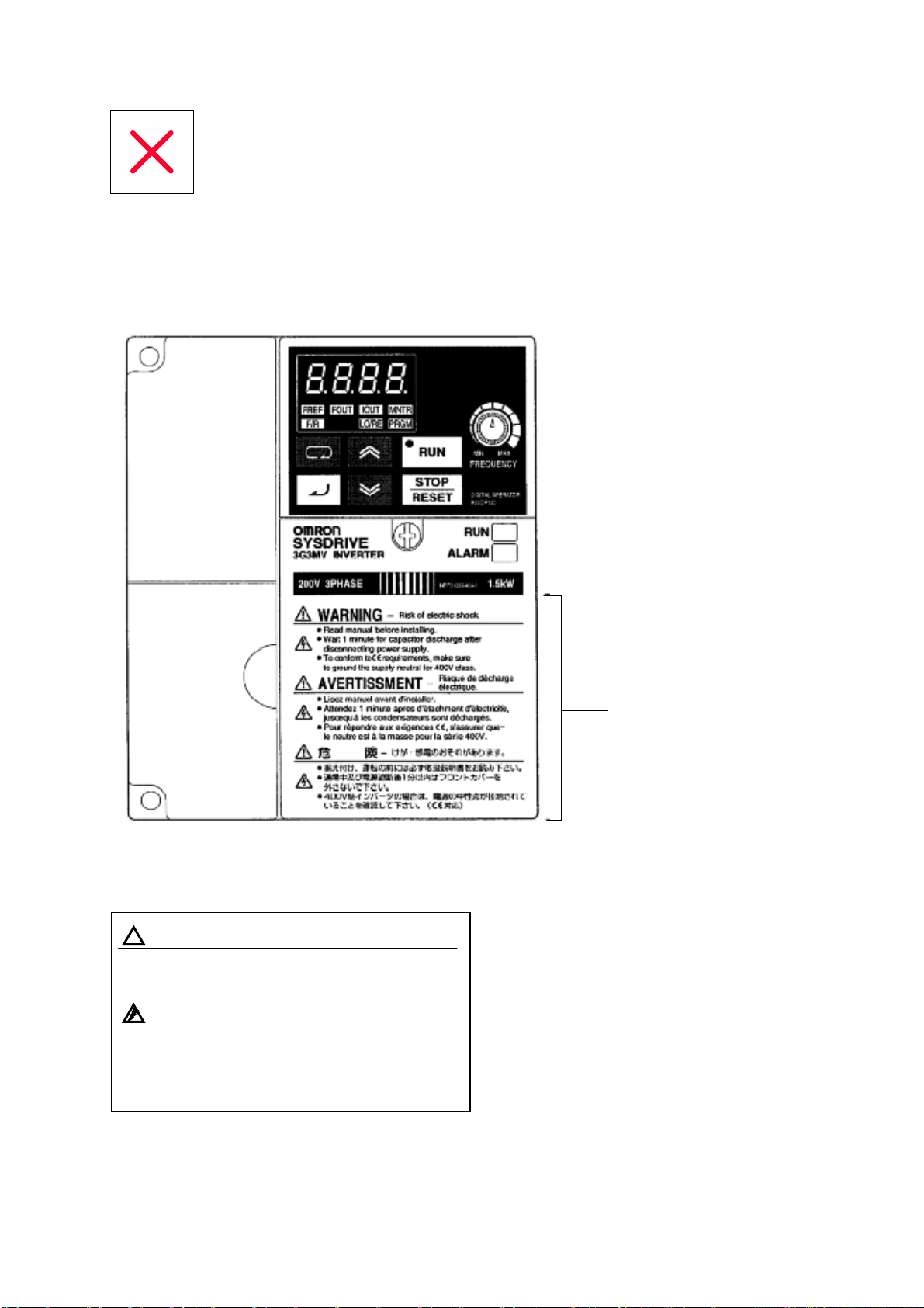
Предупреждающие надписи
Предупреждающие надписи нанесены на изделие, как показано на иллюстрации ниже.
Убедитесь, что следуете инструкциям, данным в них.
••••
Предупреждающие надписи
••••
Содержание предупреждений
ВНИМАНИЕ Риск электрического удара
!
•
Читайте руководство перед установкой
•
После отключения питания выждите 1
мин, чтобы разрядились конденсаторы
•
Чтобы удовлетворять требованиям СЕ,
убедитесь, что заземлили нейтраль
питания для класса 400-V
Предупреждающие
надписи
Контроль перед распаковкой
• Проверка изделия
При получении всегда проверяйте, что доставленное изделие является
Инвертором серии SYSDRIVE 3G3MV, который вы заказывали.
Как только у вас возникнут проблемы с изделием, немедленно свяжитесь с
ближайшим местным офисом представительства фирмы.
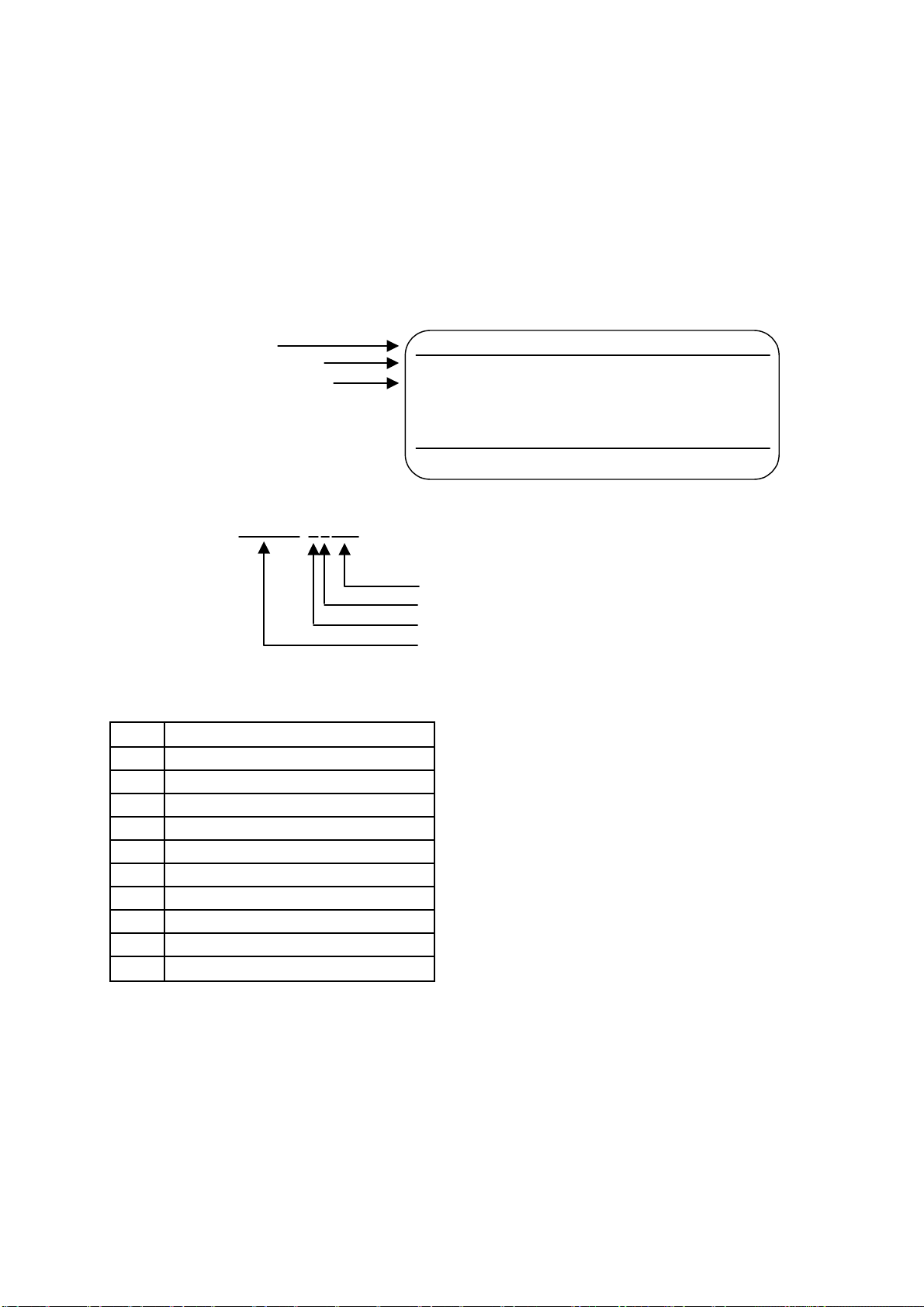
• Проверка марки изготовителя
Модель Инвертора
Входные характеристики
Выходные характеристики
omRon
INPUT : AC3PH 200-230V 50/60Hz 1.1A
OUTPUT: AC3PH 0-230V 0-400Hz 0.8A 0.3kVA
LOT NO : MASS: 0.6kg
SER NO : PRG:
FILE NO: E179149 INSTALLATION CATEGORY II
IP20
INVERTER
OMRON Corporation
• Проверка модели
3G3MV-A4007
Максимально допустимая мощность двигателя
Класс напряжения
Тип установки
Наименование серии: Серия 3G3MV
Максимально допустимая мощность двигателя
001 0.1 (0.1) kW
002 0.2 (0.25/0.37) kW
004 0.4 (0.55) kW
007 0.75(1.1)kW
015 1.5(1.5)kW
022 2.2 (2.2) kW
037 3.7 (3.7) kW
055 5.5 (5.5) kW *
075 7.5 (7.5) kW *
110 11 (11) kW*
150 15(15)kW*
3G3MV-A2001
MADE IN JAPAN
M
S
Примечание
Примечание
Цифры в скобках показывают мощности двигателей, используемых
за пределами Японии.
Мощности, отмеченные звездочками, готовятся к выпуску.

Класс напряжения
2 Вход 3-фазного напряжения 200VAC
(класс 200-V)
B Вход 1—фазного напряжения 200VAC
(класс 200-V)
4 Вход 3-фазного напряжения 400VAC
(класс 400-V)
Тип установки
А Закрытый монтаж на стену
• Проверка на повреждения
Проверьте полностью внешний вид изделия на наличие повреждений и царапин,
полученных во время транспортировки.
• Проверка принадлежностей
Помните, что данное руководство является единственной принадлежностью,
поставляемой с 3G3MV. Набор винтов и прочие необходимые приспособления
должны обеспечиваться пользователем.

Оглавление
Глава 1. Обзор . . . . . . . . . . . . . . . . . . . . . . . . . . . . . . . . . . . . . . . . . . . . . . . . . . . . .
1-1 Функции . . . . . . . . . . . . . . . . . . . . . . . . . . . . . . . . . . . . . . . . . . . . . . . . . . . . . . . . . . . . 1-2
1-2 Номенклатура . . . . . . . . . . . . . . . . . . . . . . . . . . . . . . . . . . . . . . . . . . . . . . . . . . . . . . . 1-5
1-1
Глава 2. Проектирование . . . . . . . . . . . . . . . . . . . . . . . . . . . . . . . . . . . . . . . . . . . 2-1
2-1 Монтаж . . . . . . . . . . . . . . . . . . . . . . . . . . . . . . . . . . . . . . . . . . . . . . . . . . . . . . . . . . . . 2-2
2-1-1 Размеры . . . . . . . . . . . . . . . . . . . . . . . . . . . . . . . . . . . . . . . . . . . . . . . . . . . . . 2-2
2-1-2 Условия монтажа . . . . . . . . . . . . . . . . . . . . . . . . . . . . . . . . . . . . . . . . . . . . . 2-5
2-1-3 Снятие и установка крышек . . . . . . . . . . . . . . . . . . . . . . . . . . . . . . . . . . . . . 2-7
2-2 Подключение . . . . . . . . . . . . . . . . . . . . . . . . . . . . . . . . . . . . . . . . . . . . . . . . . . . . . . . 2-10
2-2-1 Клеммный Блок . . . . . . . . . . . . . . . . . . . . . . . . . . . . . . . . . . . . . . . . . . . . . . . 2-11
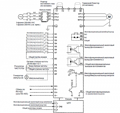
2-2-2 Стандартные подключения . . . . . . . . . . . . . . . . . . . . . . . . . . . . . . . . . . . . . 2-17
2-2-3 Подключение силовых цепей . . . . . . . . . . . . . . . . . . . . . . . . . . . . . . . . . . . 2-18
2-2-4 Подключение клемм цепей управления . . . . . . . . . . . . . . . . . . . . . . . . . . . 2-34
2-2-5 Соответствие директивам СЕ . . . . . . . . . . . . . . . . . . . . . . . . . . . . . . . . . . . 2-37
Глава 3. Подготовка к работе и мониторинг . . . . . . . . . . . . . . . . . . . . . . . . . . 3-1
3-1 Номенклатура . . . . . . . . . . . . . . . . . . . . . . . . . . . . . . . . . . . . . . . . . . . . . . . . . . . . . . . 3-2
3-1-1 Наименования элементов и их функции . . . . . . . . . . . . . . . . . . . . . . . . . . 3-2
3-1-2 Общее представление о функционировании . . . . . . . . . . . . . . . . . . . . . . . 3-4
3-2 Функция копирования и сравнения параметров . . . . . . . . . . . . . . . . . . . . . . . . . . . 3-10
3-2-1 Параметры для копирования и сравнения уставок . . . . . . . . . . . . . . . . . . 3-10
3-2-2 Процедура копирования параметров . . . . . . . . . . . . . . . . . . . . . . . . . . . . . 3-11
3-2-3 Запрет чтения параметров (Запрет записи данных в EEPROM ЦПУ) . . . 3-18
3-2-4 Ошибки копирования или сравнения параметров . . . . . . . . . . . . . . . . . . 3-19
Глава 4. Пробный Пуск . . . . . . . . . . . . . . . . . . . . . . . . . . . . . . . . . . . . . . . . . . . . 4-1
4-1 Процедуры пробного пуска . . . . . . . . . . . . . . . . . . . . . . . . . . . . . . . . . . . . . . . . . . . 4-4
4-2 Пример работы . . . . . . . . . . . . . . . . . . . . . . . . . . . . . . . . . . . . . . . . . . . . . . . . . . . . . 4-6
Глава 5. Базовые функции . . . . . . . . . . . . . . . . . . . . . . . . . . . . . . . . . . . . . . . . . 5-1
5-1 Исходные настройки . . . . . . . . . . . . . . . . . . . . . . . . . . . . . . . . . . . . . . . . . . . . . . . . . 5-2
5-1-1 Настройка запрета записи параметров/инициализации
параметров (n001) . . . . . . . . . . . . . . . . . . . . . . . . . . . . . . . . . . . . . . . . . . . . . . . . . 5-2
5-1-2 Настройка режима управления (n002) . . . . . . . . . . . . . . . . . . . . . . . . . . . . 5-3
5-2 Работа в векторном режиме управления . . . . . . . . . . . . . . . . . . . . . . . . . . . . . . . . . 5-5
5-3 Работа в режиме вольт—частотного (U/f) управления . . . . . . . . . . . . . . . . . . . . . . . 5-7
5-3-1 Настройка номинального тока двигателя (n036) . . . . . . . . . . . . . . . . . . . . 5-7
5-3-2 Настройка зависимости U/f (с n011 по n017) . . . . . . . . . . . . . . . . . . . . . . 5-7
5-4 Настройка режима Локальный/Дистанционный . . . . . . . . . . . . . . . . . . . . . . . . . . 5-10
5-5 Выбор рабочих команд . . . . . . . . . . . . . . . . . . . . . . . . . . . . . . . . . . . . . . . . . . . . . . . 5-11
i

Оглавление
5-6 Настройка эталона частоты . . . . . . . . . . . . . . . . . . . . . . . . . . . . . . . . . . . . . . . . . . 5-12
5-6-1 Выбор эталона частоты . . . . . . . . . . . . . . . . . . . . . . . . . . . . . . . . . . . . . . . . . 5-12
5-6-2 Верхний и нижний пределы эталона частоты . . . . . . . . . . . . . . . . . . . . . . 5-13
5-6-3 Регулировка аналогового входа . . . . . . . . . . . . . . . . . . . . . . . . . . . . . . . . . . 5-14
5-6-4 Настройка эталонов частоты через клавишный набор . . . . . . . . . . . . . . . 5-17
5-6-5 Настройка эталонов частоты через вход импульсного управления . . . . 5-23
5-7 Настройка времени разгона/торможения . . . . . . . . . . . . . . . . . . . . . . . . . . . . . . . . 5-24
5-8 Выбор запрета обратного вращения . . . . . . . . . . . . . . . . . . . . . . . . . . . . . . . . . . . . 5-27
5-9 Выбор режима остановки . . . . . . . . . . . . . . . . . . . . . . . . . . . . . . . . . . . . . . . . . . . . . 5-28
5-10 Многофункциональный ввод/вывод . . . . . . . . . . . . . . . . . . . . . . . . . . . . . . . . . . . 5-29
5-10-1 Многофункциональный ввод . . . . . . . . . . . . . . . . . . . . . . . . . . . . . . . . . . 5-29
5-10-2 Многофункциональный вывод . . . . . . . . . . . . . . . . . . . . . . . . . . . . . . . . . 5-33
5-11 Многофункциональный аналоговый выход и импульсный выход
контроля . . . . . . . . . . . . . . . . . . . . . . . . . . . . . . . . . . . . . . . . . . . . . . . . . . . . . . . . . . 5-35
5-11-1 Настройка многофункционального аналогового выхода
(с n065 по n067) . . . . . . . . . . . . . . . . . . . . . . . . . . . . . . . . . . . . . . . . . . . . . . 5-35
5-11-2 Настройка импульсного выхода контроля (n065 и nl50) . . . . . . . . . . . . 5-36
Глава 6. Расширенные функции . . . . . . . . . . . . . . . . . . . . . . . . . . . . . . . . . . . . 6-1
6-1 Установка и регулировка точного векторного управления . . . . . . . . . . . . . . . . . 6-2
6-1-1 Установка точного векторного управления . . . . . . . . . . . . . . . . . . . . . . . . 6-2
6-1-2 Регулировка выходного момента вращения при векторном
режиме управлении . . . . . . . . . . . . . . . . . . . . . . . . . . . . . . . . . . . . . . . . . . . 6-3
6-2 Режим энергосбережения . . . . . . . . . . . . . . . . . . . . . . . . . . . . . . . . . . . . . . . . . . . . . 6-6
6-2-1 Операции энергосберегающего режима управления . . . . . . . . . . . . . . . . 6-6
6-2-2 Выполнение настройки параметров режима энергосбережения . . . . . . 6-7
6-3 PID-управление . . . . . . . . . . . . . . . . . . . . . . . . . . . . . . . . . . . . . . . . . . . . . . . . . . . . 6-13
6-3-1 Сферы применения PID-управления . . . . . . . . . . . . . . . . . . . . . . . . . . . . . 6-13
6-3-2 Операции PID-управления . . . . . . . . . . . . . . . . . . . . . . . . . . . . . . . . . . . . . 6-14
6-3-3 Типы PID-управления . . . . . . . . . . . . . . . . . . . . . . . . . . . . . . . . . . . . . . . . . 6-14
6-3-4 Блок—схема PID-управления . . . . . . . . . . . . . . . . . . . . . . . . . . . . . . . . . . . . 6-16
6-3-5 Выбор входов для задания и регулируемой величины
PID-управления . . . . . . . . . . . . . . . . . . . . . . . . . . . . . . . . . . . . . . . . . . . . . . 6-17
6-3-6 Настройки PID-управления . . . . . . . . . . . . . . . . . . . . . . . . . . . . . . . . . . . . . 6-18
6-3-7 Регулировки PID-управления . . . . . . . . . . . . . . . . . . . . . . . . . . . . . . . . . . . 6-22
6-3-8 Точная подстройка PID-управления . . . . . . . . . . . . . . . . . . . . . . . . . . . . . . 6-24
6-4 Настройка несущей частоты . . . . . . . . . . . . . . . . . . . . . . . . . . . . . . . . . . . . . . . . . . . . 6-26
6-5 Функция динамического торможения . . . . . . . . . . . . . . . . . . . . . . . . . . . . . . . . . . . . 6-29
6-6 Функция предупреждения потери скорости . . . . . . . . . . . . . . . . . . . . . . . . . . . . . . . 6-31
6-7 Функция обнаружения превышения момента вращения . . . . . . . . . . . . . . . . . . . . . 6-35
6-8 Функция компенсации момента вращения . . . . . . . . . . . . . . . . . . . . . . . . . . . . . . . . 6-37
6-9 Функция компенсации скольжения . . . . . . . . . . . . . . . . . . . . . . . . . . . . . . . . . . . . . . 6-39
6-10 Другие функции . . . . . . . . . . . . . . . . . . . . . . . . . . . . . . . . . . . . . . . . . . . . . . . . . . . . 6-41
6-10-1 Обнаружение ошибки соединения ЦПУ . . . . . . . . . . . . . . . . . . . . . . . . . . 6-41
6-10-2 Функции защиты двигателя (n037 и n038) . . . . . . . . . . . . . . . . . . . . . . . . 6-41
6-10-3 Функция работы охлаждающего вентилятора (n039) . . . . . . . . . . . . . . . 6-42
6-10-4 Компенсация кратковременного пропадания питания (n081) . . . . . . . . . 6-42
6-10-5 Аварийное восстановление (n082) . . . . . . . . . . . . . . . . . . . . . . . . . . . . . . . 6-43
6-10-6 Функция скачков частоты (с n083 по n086) . . . . . . . . . . . . . . . . . . . . . . . . 6-44
6-10-7 Функция обнаружения частоты . . . . . . . . . . . . . . . . . . . . . . . . . . . . . . . . . 6-45
6-10-8 Память частоты для команд UP/DOWN (ВВЕРХ/ВНИЗ) (nl00) . . . . . . . 6-47
6-10-9 Журнал ошибок (nl78) . . . . . . . . . . . . . . . . . . . . . . . . . . . . . . . . . . . . . . . . 6-49
ii

Оглавление
Глава 7. Обмен . . . . . . . . . . . . . . . . . . . . . . . . . . . . . . . . . . . . . . . . . . . . . . . . . . . 7-1
7-1 Настройки Инвертора . . . . . . . . . . . . . . . . . . . . . . . . . . . . . . . . . . . . . . . . . . . . . . . 7-2
7-1-1 Настройка условий обмена . . . . . . . . . . . . . . . . . . . . . . . . . . . . . . . . . . . . . . 7-2
7-1-2 Выбор рабочих команд (n003) . . . . . . . . . . . . . . . . . . . . . . . . . . . . . . . . . . . 7-5
7-1-3 Выбор входа эталона частоты (n.004) . . . . . . . . . . . . . . . . . . . . . . . . . . . . . 7-6
7-1-4 Настройка многофункциональных входов (с n050 по n056) . . . . . . . . . . . 7-7
7-2 Формат сообщений обмена на BASIC . . . . . . . . . . . . . . . . . . . . . . . . . . . . . . . . . 7-9
7-3 Сообщение DSR и ответ . . . . . . . . . . . . . . . . . . . . . . . . . . . . . . . . . . . . . . . . . . . . . 7-12
7-3-1 Чтение данных (Код функции: 03 Hex) . . . . . . . . . . . . . . . . . . . . . . . . . . . . 7-12
7-3-2 Запись данных/Запись широковещательных данных
(Код функции: 10 Hex) . . . . . . . . . . . . . . . . . . . . . . . . . . . . . . . . . . . . . . . . . . . . . . 7-15
7-3-3 Тест на эхо—возврат (Код функции: 08 Hex) . . . . . . . . . . . . . . . . . . . . . . . . 7-17
7-4 Команда ВВОД (Enter) . . . . . . . . . . . . . . . . . . . . . . . . . . . . . . . . . . . . . . . . . . . . . . 7-20
7-5 Настройка данных обмена. . . . . . . . . . . . . . . . . . . . . . . . . . . . . . . . . . . . . . . . . . . 7-21
7-6 Назначение номеров регистров в деталях . . . . . . . . . . . . . . . . . . . . . . . . . . . . . . 7-23
7-6-1 Функции ввода/вывода. . . . . . . . . . . . . . . . . . . . . . . . . . . . . . . . . . . . . . . . . 7-23
7-6-2 Функции контроля . . . . . . . . . . . . . . . . . . . . . . . . . . . . . . . . . . . . . . . . . . . . 7-25
7-7 Коды ошибок обмена. . . . . . . . . . . . . . . . . . . . . . . . . . . . . . . . . . . . . . . . . . . . . . . 7-29
7-8 Тест самодиагностики . . . . . . . . . . . . . . . . . . . . . . . . . . . . . . . . . . . . . . . . . . . . . 7-31
7-9 Обмен с Программируемым Контроллером . . . . . . . . . . . . . . . . . . . . . . . . . . . . 7-32
7-9-1 Возможные Программируемые Контроллеры
и периферийные устройства . . . . . . . . . . . . . . . . . . . . . . . . . . . . . . . . . . . . 7-32
7-9-2 Проводное подключение шин канала обмена. . . . . . . . . . . . . . . . . . . . . . . 7-35
7-9-3 Основы макрофункций протокола. . . . . . . . . . . . . . . . . . . . . . . . . . . . . . . . 7-36
7-9-4 Создание файла проекта. . . . . . . . . . . . . . . . . . . . . . . . . . . . . . . . . . . . . . . . 7-41
7-9-5 Релейно—контактная программа. . . . . . . . . . . . . . . . . . . . . . . . . . . . . . . . . . 7-51
7-9-6 Время реакции обмена . . . . . . . . . . . . . . . . . . . . . . . . . . . . . . . . . . . . . . . . . 7-56
Глава 8. Техническое обслуживание . . . . . . . . . . . . . . . . . . . . . . . . . . . . . . . . 8-1
8-1 Функции защиты и диагностики . . . . . . . . . . . . . . . . . . . . . . . . . . . . . . . . . . . . . . 8-2
8-1-1 Обнаружение неисправностей (Фатальные ошибки) . . . . . . . . . . . . . . . . . . 8-2
8-1-2 Обнаружение предупреждений (Нефатальные ошибки) . . . . . . . . . . . . . . 8-9
8-2 Поиск и устранение неисправностей . . . . . . . . . . . . . . . . . . . . . . . . . . . . . . . . . . 8-14
8-2-1 Не удается задать параметр . . . . . . . . . . . . . . . . . . . . . . . . . . . . . . . . . . . . . 8-14
8-2-2 Невозможно запустить двигатель . . . . . . . . . . . . . . . . . . . . . . . . . . . . . . . . 8-14
8-2-3 Двигатель вращается не в том направлении . . . . . . . . . . . . . . . . . . . . . . . 8-17
8-2-4 Двигатель не выдает момент вращения или разгон слишком медленный 8-17
8-2-5 Низкая точность Инвертора в отработке скорости вращения
на высоких скоростях в векторном режиме . . . . . . . . . . . . . . . . . . . . . . . . 8-18
8-2-6 Низкая скорость торможения двигателя . . . . . . . . . . . . . . . . . . . . . . . . . . 8-18
8-2-7 Двигатель опрокидывается при динамическом торможении
активной нагрузки . . . . . . . . . . . . . . . . . . . . . . . . . . . . . . . . . . . . . . . . . . . . . 8-18
8-2-8 Перегрев двигателя . . . . . . . . . . . . . . . . . . . . . . . . . . . . . . . . . . . . . . . . . . . . 8-19
8-2-9 Контроллер или АМ—радио принимают помеху при пуске Инвертора . . 8-20
8-2-10 Прерыватель при аварии заземления срабатывает при пуске
Инвертора . . . . . . . . . . . . . . . . . . . . . . . . . . . . . . . . . . . . . . . . . . . . . . . . . . . 8-20
8-2-11 Механическяие вибрации . . . . . . . . . . . . . . . . . . . . . . . . . . . . . . . . . . . . . . 8-21
8-2-12 PID-управление нестабильное или совсем не выполняется . . . . . . . . . . 8-21
8-2-13 Инвертор вибрирует в режиме энергосбережения . . . . . . . . . . . . . . . . . 8-22
8-2-14 Двигатель вращается после отключения выхода Инвертора . . . . . . . . . 8-23
8-2-15 Обнаружение 0 V и потеря скорости при пуске двигателя . . . . . . . . . . . 8-23
8-2-16 Выходная частота не достигает эталона . . . . . . . . . . . . . . . . . . . . . . . . . . 8-23
iii

Оглавление
8-3 Техническое Обслуживание и Проверка . . . . . . . . . . . . . . . . . . . . . . . . . . . . . . . 8-24
Глава 9. Характеристики . . . . . . . . . . . . . . . . . . . . . . . . . . . . . . . . . . . . . . . . . . 9-1
9-1 Характеристики Инвертора . . . . . . . . . . . . . . . . . . . . . . . . . . . . . . . . . . . . . . . . . . . 9-2
Глава 10. Список Параметров . . . . . . . . . . . . . . . . . . . . . . . . . . . . . . . . . . . . . . 10-1
Глава 11. Использование Инвертора для управления двигателем . . . . . . 11-1
iv

Обзор
••••
1-1 Функции
1-2
Номенклатура
Глава 1
••••

Обзор
Глава 1
1-1 Функции
Многофункциональный компактный Инвертор серии SYSDRIVE 3G3MV
является первым компактным Инвертором, незаменимым при создании
систем с разомкнутым векторным управлением. Инвертор 3G3MV
удовлетворяет Директивам ЕС и требованиям Стандартов UL/cUL, которые
используются во всем мире.
Более того, Инвертор серии 3G3MV объединяет в себе различные методы
управления, сети и функции ввода/вывода, гибкие и легкие в
использовании.
• Модели Инвертора SYSDRIVE 3G3MV
• Имеются следующие модели 3G3MV класса 200-V (3-фазные и 1-фазные 200 VAC) и
класса 400-V (3-фазные 400 VAC).
Номинальное
напряжение Тип защиты
3-фазное 200 VAC Закрытый,
для монтажа на стену
(соответствует IP20)
1—фазное 200 VAC
Закрытый,
для монтажа на стену
соответствует IP20)
Максимально
допустимая мощность
двигателя
0.1 (0.1) kW 3G3MV-A2001
0.2 (0.25) kW 3G3MV-A2002
0.4 (0.55) kW 3G3MV-A2004
0.75(1.1)kW 3G3MV-A2007
1.5(1.5) kW 3G3MV-A2015
2.2 (2.2) kW 3G3MV-A2022
3.7 (3.7) kW 3G3MV-A2037
5.5 (5.5) kW 3G3MV-A2055*
7.5 (7.5) kW 3G3MV-A2075*
11 (11) kW 3G3MV-A2110*
15(15)kW 3G3MV-A2150*
0.1 (0.1) kW 3G3MV-AB001
0.2 (0.25) kW 3G3MV-AB002
0.4 (0.55) kW 3G3MV-AB004
0.75(1.1)kW 3G3MV-AB007
1.5(1.5)kW 3G3MV-AB015
2.2 (2.2) kW 3G3MV-AB022
3.7 (3.7) kW 3G3MV-AB037
Модель
1-2

Обзор
Глава 1
Номинальное
напряжение Тип защиты
3-фазное 400 VAC Закрытый,
для монтажа на стену
(соответствует IP20)
Примечание
Модели, отмеченные звездочкой, готовятся к выпуску.
Максимально
допустимая мощность
двигателя
0.2 (0.37) kW 3G3MV-A4002
0.4 (0.55) kW 3G3MV-A4004
0.75(1.1)kW 3G3MV-A4007
1.5 (2.2) kW 3G3MV-A4015
2.2 (3.7) kW 3G3MV-A4022
3.7 (3.7) kW 3G3MV-A4037
5.5 (5.5) kW 3G3MV-A4055*
7.5 (7.5) kW 3G3MV-A4075*
11 (11) kW 3G3MV-A4110*
15(15)kW 3G3MV-A4150*
Модель
• Высокий момент вращения, идеальный для различных
применений
Инвертор 3G3MV является первым компактным Инвертором OMRON со встроенной
функцией разомкнутого векторного управления, который гарантирует момент
вращения на выходе, составляющий 150% от номинального момента вращения
двигателя при выходной частоте 1 Гц.
Обеспечивает более стабильное вращение на низких частотах, чем у любых
инверторов подобного типа. Более того, Инвертор 3G3MV подавляет колебания,
вызываемые нагрузкой.
Включает полностью автоматическую функцию усиления момента вращения, которая
делает более мощной работу двигателя при вольт-частотном (U/f) управлении.
Имеет высокоскоростную функцию ограничения тока, подавляющую превышение тока,
вызванное высоким моментом вращения, и гарантирующую плавную работу двигателя.
• Удобные и легкие в использовании функции
•Регулятор ЧАСТОТЫ в Цифровом Пульте Управления (ЦПУ) позволяет легко
выполнить операцию регулирования. По умолчанию принимается режим
функционирования согласно настройкам регулятора ЧАСТОТЫ.
•Цифровой Пульт Управления имеет функцию копирования параметров,
гарантирующую легкое изменение параметров.
•Обеспечивается легкость технического обслуживания. Охлаждающий вентилятор
легко заменяется. Срок службы вентилятора может быть увеличен, если включать его
только при работающем Инверторе.
•Имеется встроенный управляющий транзистор. Кроме того, Инвертор будет
обеспечивать более эффективное управление при непосредственном подключении
Тормозного Резистора.
•Имеет встроенную цепь защиты от бросков тока, которая предотвращает плавление
контактов на блоке питания.
1-3

Обзор
Глава 1
• Международные Стандарты (Директивы EC и Стандарты
UL/cUL)
Инвертор 3G3MV удовлетворяет Директивам ЕС и требованиям Стандартов UL/cUL,
которые используются во всем мире.
Классификация Применяемые Стандарты
Директива EMC EN50081-2 и EN5008-2Директивы EC
Директива для
низковольтового
оборудования
UL/cUL UL508C
prEN50178
• Совместимость с интерфейсами CompoBus/D и RS-422/485
• Поддерживает обмен по RS-422 и RS-485, согласующийся с Протоколом Обмена
MODBUS, что делает возможным легко строить сети с использованием Макрофункций
Протокола или с использованием Блока ASCII, установленного в Программируемый
Контроллер OMRON семейства SYSMAC. Протокол обмена MODBUS является
торговой маркой фирмы AEG Schneider Automation.
• Подключается к Блоку Обмена 3G3MV-PDRT1-SINV сети CompoBus/D. Инвертору
3G3MV доступны функции удаленного ввода/вывода в сети CompoBus/D, которые
гарантируют легкий обмен, как при стандартном вводе/выводе. Более того, обмен по
CompoBus/D соответствует обмену по протоколу DeviceNet для открытых сетей, что
позволяет создавать сети, в которых могут сосуществовать устройства других
компаний.
• Подключение различных сигналов ввода/вывода
Подключаются различные сигналы ввода/вывода для широкого диапазона
применений, как описано ниже.
•Аналоговый вход напряжения: от 0 до 10 V
•Аналоговый вход тока: от 4 до 20 mA или от 0 до 20 mA
•Вход импульсного управления: от 0.1 до 33.0 kHz (задается параметром)
•Многофункциональный аналоговый выход или выход импульсного управления,
выбираемый в качестве выхода слежения.
• Подавление Гармоник
Подключается к реактору постоянного тока, который подавляет гармоники более
эффективно, чем соответствующие реакторы переменного тока.
Дальнейшее совершенствование процесса подавления гармоник возможно при
комбинированном использовании реакторов постоянного и переменного тока.
1-4
Обзор
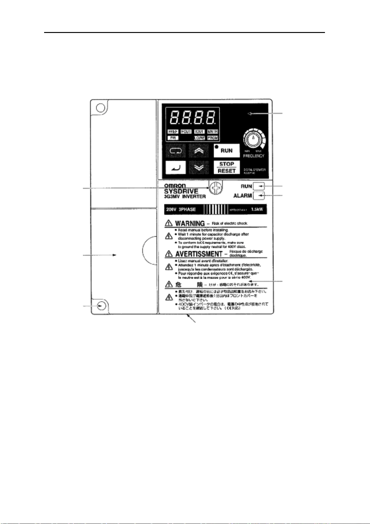
1-2 Номенклатура
•
Панель
Винт
крепления
передней
панели
Глава 1
Цифровой
Пульт
Уп
авления
Индикатор РАБОТА
ТРЕВОГА
Экран
Крышка
клеммного
блока
Передняя
крышка
Нижняя крышка
Примечание
монтажных отверстий. Вместо этого в качестве крышки клеммного блока используется
передняя крышка, а на месте монтажных отверстий имеются две U-образных выемки.
3G3MV-A2001 (0.1 kW), 3G3MV-A2002 (0.2 kW), 3G3MV-A2004 (0.4 kW) и 3G3MV-A2007
(0.75 kW)
3G3MV-AB001 (0.1 kW), 3G3MV-AB002 (0.2 kW) и 3G3MV-AB004 (0.4 kW)
Ни одна из следующих моделей не имеет крышки клеммного блока или
1-5
Обзор
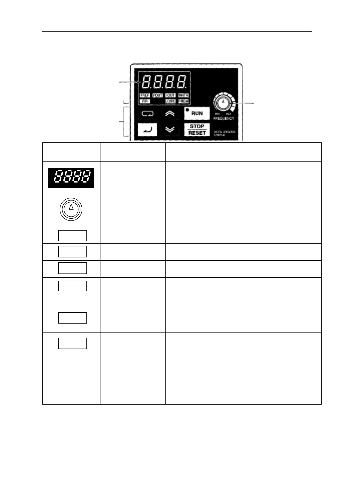
• Цифровой Пульт Управления
Экран данных
Светодиодные
индикаторы
Рабочие клавиши
Глава 1
Регулятор
ЧАСТОТЫ
Элемент
пульта
. . . .
MIN MAX
IOUT
Наименование Функция
Экран данных
Регулятор
ЧАСТОТЫ
Индикатор FREF
Индикатор FOUT
Индикатор IOUT
Индикатор MNTR
Индикатор F/R
Индикатор LO/RE
Отображает требуемые данные, такие как
эталон частоты, выходная частота или
значение задаваемого параметра.
Задает эталон частоты в диапазоне от 0 Гц
до максимальной частоты.
Пока горит этот индикатор, можно
контролировать или задавать эталон частоты.
Пока горит этот индикатор, можно
контролировать выходную частоту Инвертора.
Пока горит этот индикатор, можно
контролировать выходной ток Инвертора.
Пока горит этот индикатор, можно контролировать значения в позициях индикации
(многофункциональный контроль) с U01 по
U10.
Пока горит этот индикатор, может быть
выбрано направление вращения, когда
Инвертор запускается через клавишу RUN.
Пока горит этот индикатор, можно выбрать,
как задается работа Инвертора: через
Цифровой Пульт Управления или согласно
установленным параметрам.
Примечание
состояние этого индикатора можно только
контролировать. Пока горит этот
индикатор, любой ввод команд рабочего
режима игнорируется.
Когда Инвертор в работе,
1-6
Обзор
Глава 1
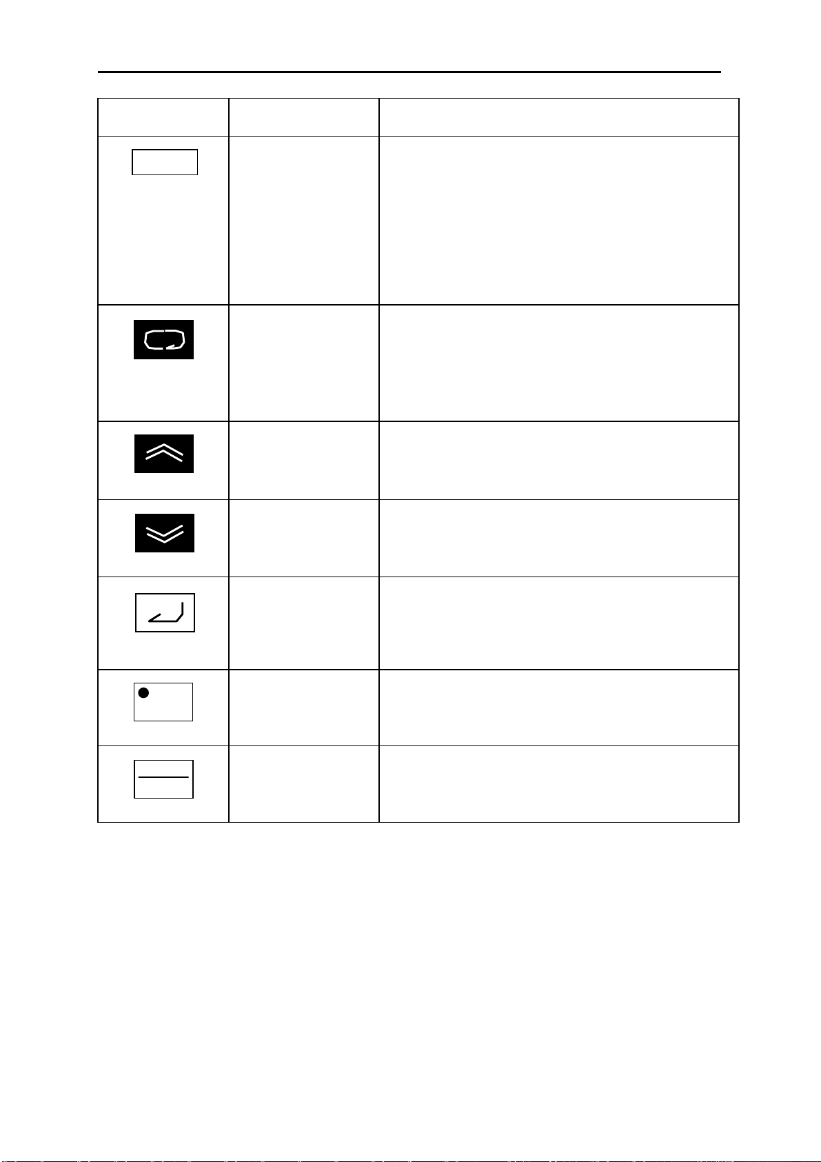
Элемент
льта
п
Наименование Функция
Индикатор PRGM
Клавиша Режима
Клавиша
Инкремента
Пока горит этот индикатор, могут быть заданы
и проконтролированы параметры с n001 по
n179.
Примечание
параметры можно только контролировать,
и только несколько параметров можно
изменить. Пока горит этот индикатор,
любой ввод команд рабочего режима
игнорируется.
Последовательное переключение между
светодиодными индикаторами (для контроля
и задания параметров).
Задание параметру будет отменено, если эта
клавиша нажата прежде, чем выполнен ввод
задания.
Увеличивает номер позиции индикации
(многофункционального контроля), номер
параметра или значение уставки параметра.
Пока Инвертор в работе,
RUN
STOP
RESET
Клавиша
Декремента
Клавиша Ввода Вводит номер позиции индикации
Клавиша РАБОТА
Клавиша
СТОП/СБРОС
Уменьшает номер позиции индикации
(многофункционального контроля), номер
параметра или значение уставки параметра.
(многофункционального контроля), номер
параметра или значение уставки после того,
как они были заданы или изменены.
Начинает запуск Инвертора, когда 3G3MV
работает через Цифровой Пульт Управления.
Останавливает Инвертор, пока не задан
параметр n007, запрещающий действие
клавиши СТОП.
1-7

Глава 2
П
••••
2-1 Монтаж
2-2 Подключение
роектирование
••••
Проектирование Глава 2
2-1 Монтаж
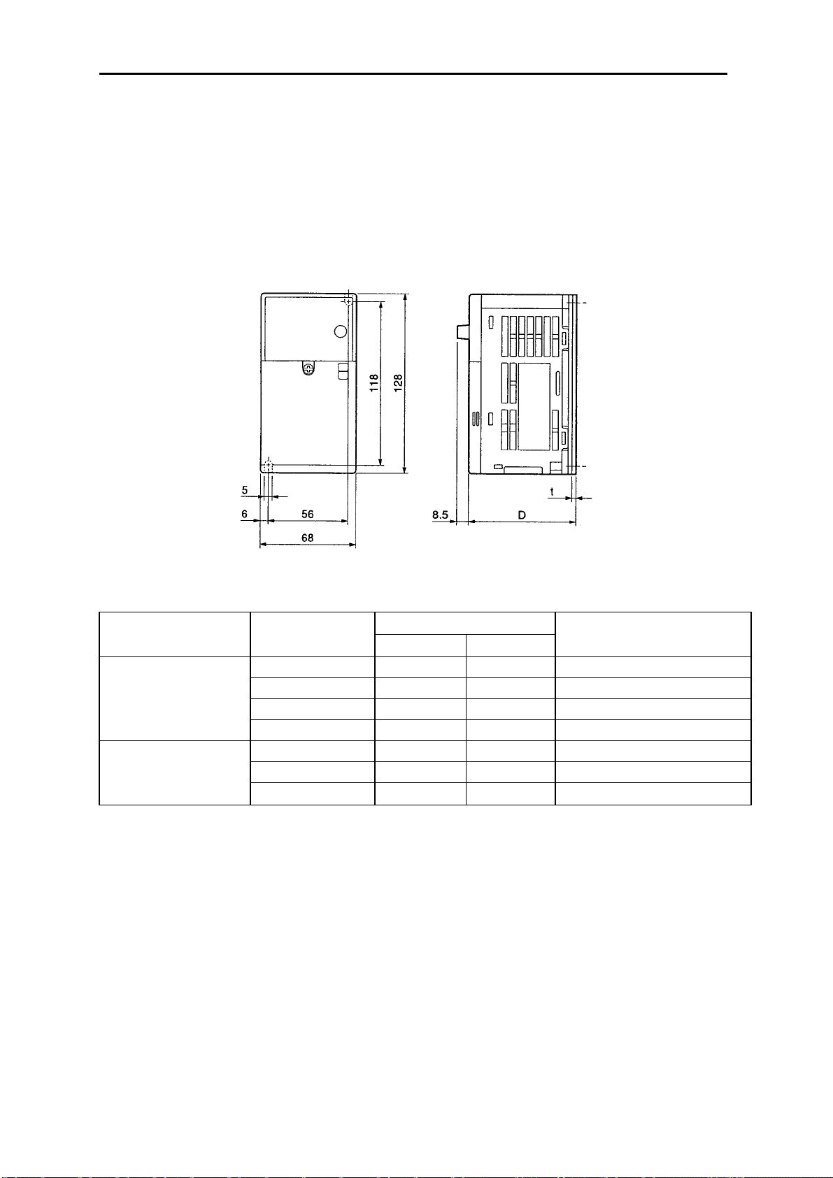
2-1-1 Размеры
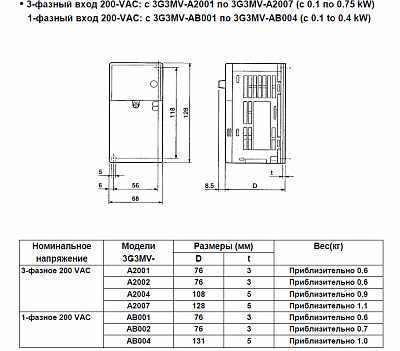
3-фазный вход 200-VAC: с 3G3MV-A2001 по 3G3MV-A2007 (с 0.1 по 0.75 kW)
•
1-фазный вход 200-VAC: с 3G3MV-AB001 по 3G3MV-AB004 (с 0.1 to 0.4 kW)
напряжение
3-фазное 200 VAC
1-фазное 200 VAC
Модели
3G3MV-
A2001 76 3 Приблизительно 0.6
A2002 76 3 Приблизительно 0.6
A2004 108 5 Приблизительно 0.9
A2007 128 5 Приблизительно 1.1
AB001 76 3 Приблизительно 0.6
AB002 76 3 Приблизительно 0.7
AB004 131 5 Приблизительно 1.0
Размеры (мм)Номинальное
Dt
Вес(кг)
2-2
Проектирование Глава 2
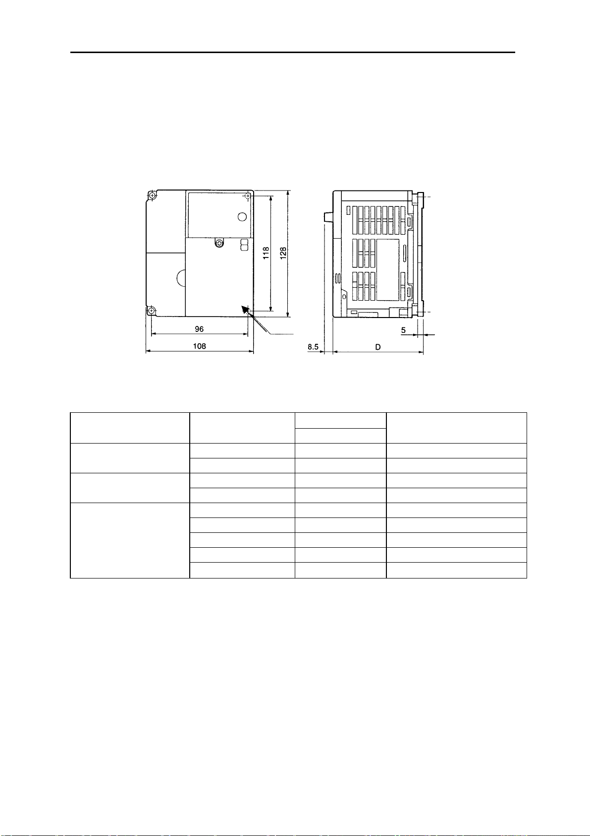
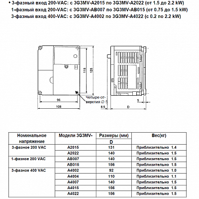
3-фазный вход 200-VAC: с 3G3MV-A2015 по 3G3MV-A2022 (от 1.5 до 2.2 kW)
•
1—фазный вход 200-VAC: с 3G3MV-AB007 по 3G3MV-AB01 5 (от 0.75 до 1.5 kW)
3-фазный вход 400-VAC: с 3G3MV-A4002 по 3G3MV-A4022 (с 0.2 по 2.2 kW)
Четыре от-
верстия ∅ 5
напряжение
3-фазное 400 VAC
Модели 3G3MV-
Размеры (мм)Номинальное
Вес(кг)
D
A2015 131 Приблизительно 1.4 3-фазное 200 VAC
A2022 140 Приблизительно 1.5
AB007 140 Приблизительно 1.5 1-фазное 200 VAC
AB015 156 Приблизительно 1.5
A4002 92 Приблизительно 1.0
A4004 110 Приблизительно 1.1
A4007 140 Приблизительно 1.5
A4015 156 Приблизительно 1.5
A4022 156 Приблизительно 1.5
2-3
Проектирование Глава 2
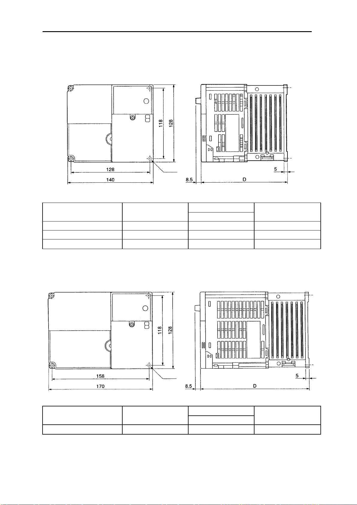
3-фазный вход 200-VAC: 3G3MV-A2037 (3.7 kW)
•
1-фазный вход 200-VAC: 3G3MV-AB022 (2.2 kW)
3-фазный вход 400-VAC: 3G3MV-A4037 (3.7 kW)
Модели 3G3MV-
напряжение
3-фазное 200 VAC A2037 143 Приблизительно 2.1
1-фазное 200 VAC AB022 163 Приблизительно 2.2
3-фазное 400 VAC A4037 143 Приблизительно 2.1
3-фазный вход 200-VAC: 3G3MV-AВ037 (3.7 kW)
•
Размеры (мм)Номинальное
D
Вес(кг)
Модели 3G3MV-
напряжение
1-фазное 200 VAC AB037 180 Приблизительно 2.9
2-4
Размеры (мм)Номинальное
D
Вес(кг)

Проектирование Глава 2
2-1-2 Условия монтажа
!
Внимание
положении и обеспечиваете требуемые зазоры между Инвертором и
управляющей панелью или другими устройствами. Невыполнение этого
может привести к возгоранию или нарушению функционирования изделия.
!
Внимание
Невыполнение этого может привести к возгоранию или нарушению
функционирования изделия.
!
Внимание
привести к выходу из строя или нарушению функционирования изделия.
!
Внимание
соответствующее устройство останова с машинной стороны изделия
(имеющийся тормоз не является устройством останова, гарантирующим
безопасность). Невыполнение этого может привести к травме.
!
Внимание
которое обеспечавает немедленное прекращение работы и прерывание
питания. Невыполнение этого может привести к травме.
Убедитесь, что устанавливаете изделие в правильном
Не допускайте попадания инородных предметов внутрь изделия.
Не допускайте сильных толчков. Невыполнение этого может
Чтобы гарантировать безопасность, предусмотрите
Предусмотрите внешнее устройство аварийного останова,
2-5
Проектирование Глава 2
• Положение при монтаже и размеры
• Устанавливайте Инвертор при следующих условиях:
Температура окружающей среды в рабочем режиме (для монтажа в панель):
от -10°C до 50°C.
Влажность: 90% и менее (без конденсации).
• Устанавливайте Инвертор в чистом месте, свободном от масляных брызг и пыли. В
противном случае устанавливайте его в полностью закрытую панель, которая
защищена от взвешенной в воздухе пыли.
• Когда устанавливаете или работаете с Инвертором, всегда предпринимайте
специальные меры предосторожности, чтобы металлическая пыль, масло, вода или
другие посторонние материалы не попали в Инвертор.
• Не устанавливайте Инвертор на легковоспламеняющиеся материалы, такие как
дерево.
• Положение
• Устанавливайте Инвертор на вертикальной поверхности, так чтобы надписи на
табличке были сориентированы в нужном направлении.
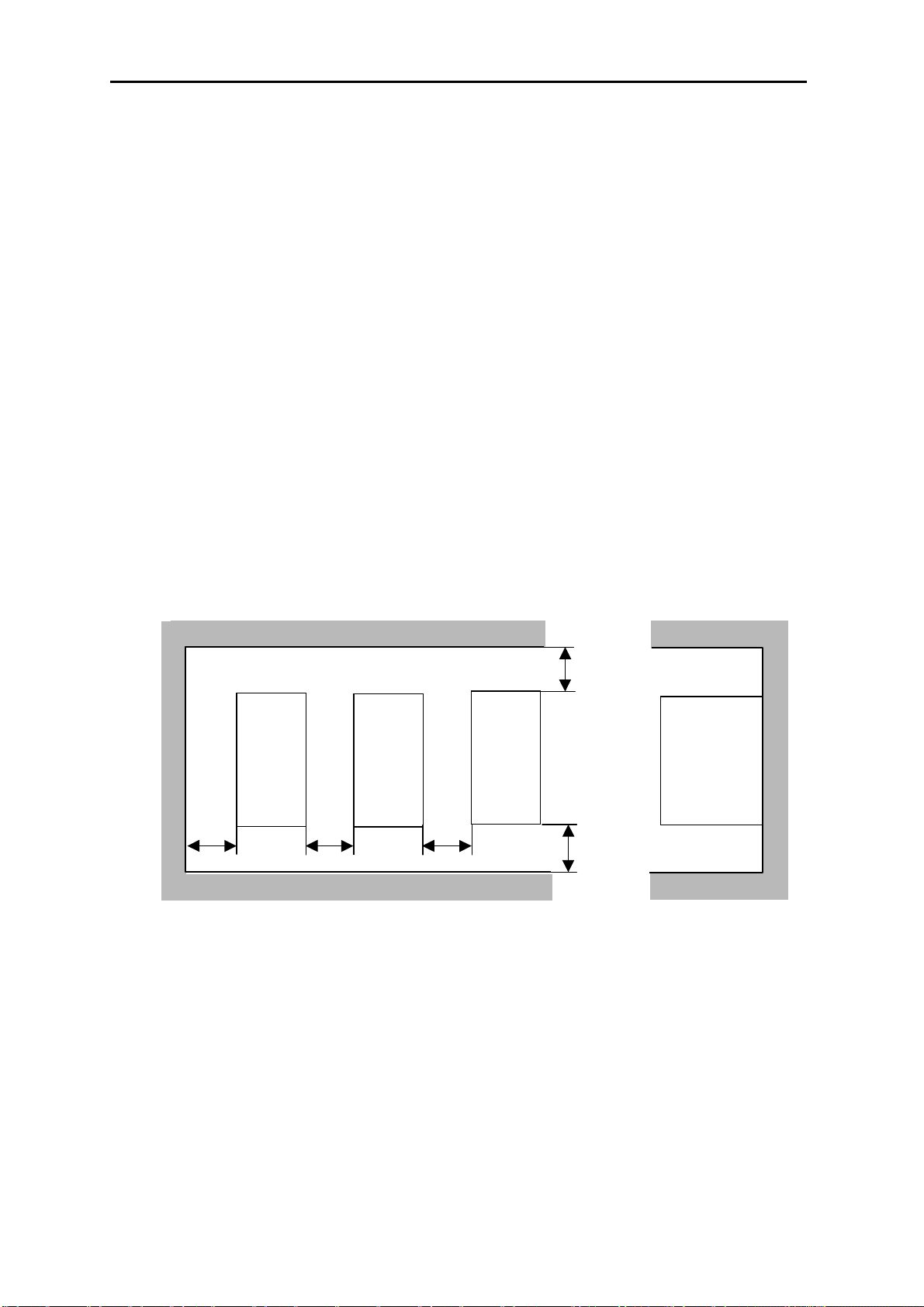
• Размеры
• Когда устанавливаете Инвертор, всегда предусматривайте следующие зазоры, чтобы
обеспечивался нормальный отвод тепла от Инвертора.
W = 30 мм минимум
Инвертор
Инвертор
Инвертор
100 мм мин. Воздух
Боковая
сторона
100 мм мин. Воздух
• Контроль окружающей температуры
• Чтобы увеличить надежность работы, необходимо устанавливать Инвертор в
условиях, свободных от резких колебаний температуры.
• Если Инвертор установлен в закрытую среду, например в контейнер, используйте
охлаждающий вентилятор или воздушный кондиционер, чтобы поддерживать
температуру воздуха внутри ниже 50°C. Срок службы встроенных
электролитических конденсаторов Инвертора можно продлить, если поддерживать
температуру воздуха внутри настолько низкой, насколько это возможно.
2-6

Проектирование Глава 2
• Температура поверхности Инвертора может быть выше приблизительно на 30°C, чем
температура окружающей среды. Убедитесь, что разместили оборудование и провода
настолько далеко от Инвертора, насколько это возможно, если это оборудование и
провода легко воспламеняются при воздействии тепла.
• Защита Инвертора от инородных материалов в процессе
установки
• Установите крышку на Инвертор на время монтажа, чтобы защитить его от
металлической пыли, возникающей при сверлении.
По завершении монтажа всегда снимайте крышку с Инвертора. В противном случае
вентиляция будет недостаточной, что приведет к перегреву Инвертора.
2-1-3 Снятие и установка крышек
Чтобы установить Инвертор, необходимо снять переднюю крышку, крышку клеммного
блока (если Инвертор не модели 200-V) и Цифровой Пульт Управления. Чтобы
подключить Инвертор, необходимо снять переднюю крышку, крышку клеммного блока
(если Инвертор не модели 200-V) и нижнюю крышку. Ниже приведены инструкции, как
снимать крышки. Для установки крышек выполните шаги в обратном порядке.
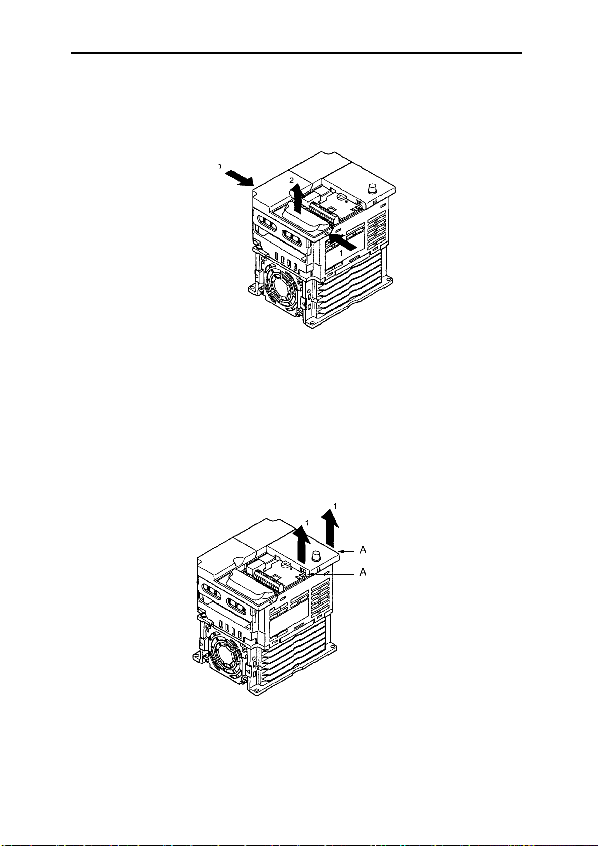
• Снятие передней крышки
• Освободите с помощью отвертки переднюю крышку от монтажных винтов.
• Чтобы снять переднюю крышку, надавите на левую и правую стороны крышки в
направлении стрелок 1 и поднимите нижнюю часть крышки в направлении стрелки 2,
как показано на иллюстрации ниже.
2-7
Проектирование Глава 2
• Снятие крышки клеммного блока
• После того, как передняя крышка снята, нажмите на левую и правую стороны крышки
клеммного блока в направлении стрелок 1 и поднимите ее в направлении стрелки 2,
как показано на иллюстрации ниже.
Примечание
блока. В качестве этой крышки используется передняя крышка.
3G3MV-A2001 (0.1 kW), 3G3MV-A2002 (0.2 kW), 3G3MV-A2004 (0.4 kW) и 3G3MVA2007 (0.75 kW)
3G3MV-AB001 (0.1 kW), 3G3MV-AB002 (0.2 kW) и 3G3MV-AB004 (0.4 kW)
Ни одна из следующих моделей 200-V не имеет крышки клеммного
• Снятие Цифрового Пульта Управления
• После снятия передней крышки поднимите верхнюю и нижнюю части правой стороны
(позиция А) Цифрового Пульта Управления в направлении стрелок 1, как показано на
иллюстрации ниже.
2-8
Проектирование Глава 2
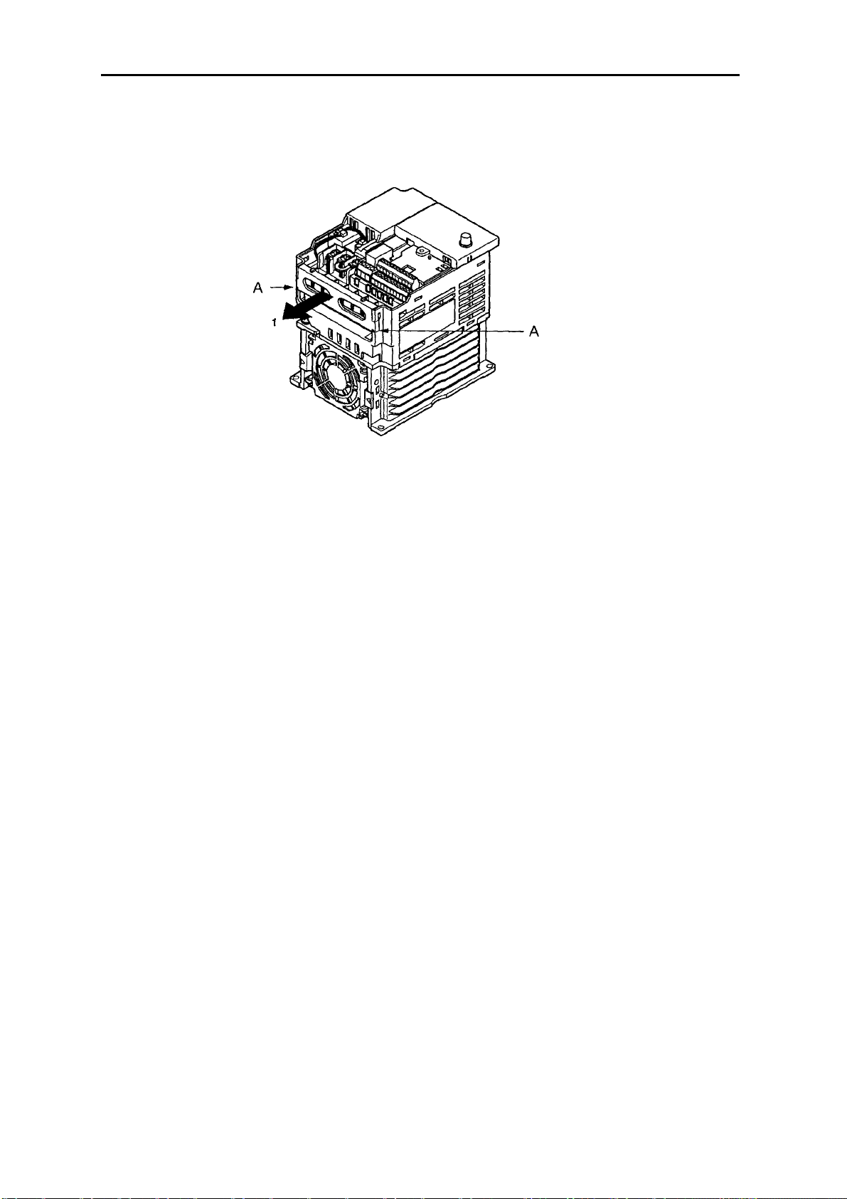
• Снятие нижней крышки
• После снятия передней крышки и крышки клеммного блока нажмите на нижнюю
крышку в направлении стрелки 1, используя в качестве точек опоры позиции А.
2-9
Loading…
-
Олниса
- →
-
Блог
В нашем современном мире Omron Sysdrive 3G3MV – это серия частотных преобразователей, предназначенных для управления скоростью и моментом вращения асинхронных двигателей. Частотные преобразователи, или инверторы, широко используются в промышленности для оптимизации работы электродвигателей, экономии энергии и повышения производительности. Omron, японская корпорация, известная своими инновациями в области автоматизации, предлагает серию 3G3MV как надежное и эффективное решение для различных промышленных применений.

Частотные преобразователи и их роль в автоматизации
Частотные преобразователи (ЧП) играют ключевую роль в современных системах автоматизации. Они преобразуют постоянный ток в переменный и позволяют изменять частоту и амплитуду выходного напряжения, что дает возможность точно регулировать скорость вращения электродвигателей. Серия Omron Sysdrive 3G3MV представляет собой компактные и функциональные частотные преобразователи, разработанные для малого и среднего бизнеса, где важны гибкость и простота интеграции. Основные функции использования ЧП включают:
- Энергоэффективность: регулирование скорости двигателя позволяет значительно экономить энергию.
- Улучшение производительности: плавное изменение скорости обеспечивает оптимальное управление технологическими процессами.
- Продление срока службы оборудования: уменьшение механических нагрузок за счет плавного пуска и торможения.
Технические характеристики
Устройство обладает следующим рядом характеристик:
- Диапазон мощности: Преобразователи 3G3MV охватывают широкий диапазон мощностей от 0,2 кВт до 7,5 кВт, что делает их подходящими для различных применений.
- Напряжение питания: Они могут работать в сетях с напряжением 200-240 В или 380-480 В, что обеспечивает совместимость с разными системами электроснабжения.
- Диапазон частот: Выходная частота преобразователей варьируется от 0,5 Гц до 400 Гц, что позволяет точно регулировать скорость вращения двигателя.
- Управление скоростью: Поддерживаются различные режимы управления, включая векторное управление без датчика скорости и управление U/f.
- Коммуникации и интерфейсы: ЧП имеют встроенные интерфейсы для подключения к системам управления, включая последовательный интерфейс RS-485.
Преимущества
Данный аппарат является востребованным на рынке благодаря следующим преимуществам:
- Компактный дизайн: Omron 3G3MV отличается небольшими размерами и весом, что упрощает его установку в ограниченных пространствах.
- Простота использования: Интуитивно понятный интерфейс и широкие возможности конфигурации облегчают настройку и эксплуатацию.
- Надежность: Высокая надежность и долговечность оборудования обеспечиваются за счет качественных компонентов и передовых технологий Omron.
- Гибкость применения: Преобразователи 3G3MV могут использоваться в различных отраслях, таких как водоснабжение, вентиляция, обрабатывающая промышленность и другие.

Область применения
Omron Sysdrive 3G3MV широко используется в различных областях промышленности благодаря своей универсальности и надежности. Рассмотрим несколько примеров:
- Системы водоснабжения и водоотведения: Использование частотных преобразователей для управления насосами позволяет оптимизировать работу систем водоснабжения, снижать энергопотребление и уменьшать износ оборудования.
- Системы HVAC (отопление, вентиляция и кондиционирование): Преобразователи помогают эффективно управлять скоростью вентиляторов и насосов, обеспечивая комфортные условия и экономию энергии.
- Производственные линии: Векторное управление двигателями на производственных линиях обеспечивает точный контроль скорости и момента, что особенно важно для точных технологических процессов.
- Обработка материалов: в таких отраслях, как деревообработка или металлообработка, точное управление скоростью резки и подачи материалов улучшает качество продукции и увеличивает производительность.
Таким образом, Omron Sysdrive 3G3MV представляет собой надежное и эффективное решение для управления асинхронными двигателями в различных промышленных применениях. Сочетая в себе компактный дизайн, простоту использования и широкие функциональные возможности, эти частотные преобразователи способствуют улучшению производительности и снижению эксплуатационных затрат. Понимание и использование таких передовых технологий автоматизации является ключевым элементом в повышении конкурентоспособности и устойчивости современных предприятий.
Содержание
- 3G3MV
- Omron SYSDRIVE 3G3MV SERIES Manuals
- 4 User Guides and Instruction Manuals found for Omron SYSDRIVE 3G3MV SERIES
- Omron SYSDRIVE 3G3MV SERIES Operation & User’s Manual (348 pages)
- Omron SYSDRIVE 3G3MV SERIES System Configuration Manual (10 pages)
- Omron SYSDRIVE 3G3MV SERIES Operation & User’s Manual (344 pages)
- Omron SYSDRIVE 3G3MV SERIES Setup Manual (106 pages)
- Frequently asked Questions:
- Is this Omron SYSDRIVE 3G3MV SERIES manual is an official manufacturer’s documentation?
- In what e-format presented Omron SYSDRIVE 3G3MV SERIES documentation?
- Is it safe to download the Omron SYSDRIVE 3G3MV SERIES PDF manual?
- Omron SYSDRIVE 3G3MV SERIES Compatible Manuals:
- Omron KP100L Datasheet
- Omron CIMR-J7AZ — QUICK Manual
- Omron MX2 — 1 Operation & user’s manual
- Omron SYSDRIVE 3G3HV SERIES Operation & user’s manual
- Omron SYSDRIVE 3G3JV Operation & user’s manual
- Related Devices:
- Omron SYSDRIVE 3G3MV SERIES Optional Materials:
- инструкция по эксплуатации OMRON 3G3MV
- ОТКАЗ ОТ ОТВЕТСТВЕННОСТИ ЗА СКАЧИВАНИЕ ИНСТРУКЦИИ OMRON 3G3MV
- Omron sysdrive 3g3mv инструкция
3G3MV
ООО «КоСПА», официальный партнер компании Yaskawa Europe, информирует, что с 01.01.2012 продукция раздела Drives & Motion, широко известная под маркой «OMRON», выпускается и продается под родной и первоначальной маркой «Yaskawa». Выше упомянутые изменения связаны с окончанием срока действия совместного предприятия OMRON Yaskawa Motion Control (OYMC), которое было создано в марте 2003 года компаниями OMRON Corporation (Япония) и Yaskawa Electric Corporation (Япония) с целью расширения присутствия на рынке Drives & Motion Европы.
За время работы совместного предприятия сменилось 2 поколения преобразователей частоты, далее представлена последовательность смены поколений:
YASKAWA 3G3MV был серией компактных преобразователей частоты:
Диапазон 0,1 Вт . 4 кВт при напряжении питания U=220 В.
Диапазон 0,2 Вт . 7,5 кВт при напряжении питания U=380 В.
V/f, Open loop vector: управление.
Рабочая перегрузка 150%/60 с.
16 предустановленных скоростей .
6 многофункциональных цифровых входов.
3 многофункциональных цифровых выхода.
1 многофункциональный аналоговый вход.
1 многофункциональный аналоговый выход.
100% момент на валу двигателя при 0,5 Гц.
Встроенный потенциометр для задания частоты.
Источник
Omron SYSDRIVE 3G3MV SERIES Manuals
4 User Guides and Instruction Manuals found for Omron SYSDRIVE 3G3MV SERIES
Omron SYSDRIVE 3G3MV SERIES Operation & User’s Manual (348 pages)
Omron SYSDRIVE 3G3MV SERIES System Configuration Manual (10 pages)
Omron SYSDRIVE 3G3MV SERIES Operation & User’s Manual (344 pages)
Omron SYSDRIVE 3G3MV SERIES Setup Manual (106 pages)
Frequently asked Questions:
Is this Omron SYSDRIVE 3G3MV SERIES manual is an official manufacturer’s documentation?
Yes, all Omron SYSDRIVE 3G3MV SERIES manuals presented on Guidessimo website are an official documentation of device manufacturer.
In what e-format presented Omron SYSDRIVE 3G3MV SERIES documentation?
All Omron SYSDRIVE 3G3MV SERIES manuals available in PDF format.
Is it safe to download the Omron SYSDRIVE 3G3MV SERIES PDF manual?
Yes, Omron SYSDRIVE 3G3MV SERIES manual was last checked on 26/12/2020.
Omron SYSDRIVE 3G3MV SERIES Compatible Manuals:
Omron KP100L Datasheet
KP100L / 18 May 2021 / #U5VD6P
Omron CIMR-J7AZ — QUICK Manual
CIMR-J7AZ — QUICK / 19 Feb 2021 / #4CQS2Y
Omron MX2 — 1 Operation & user’s manual
MX2 — 1 / 25 May 2021 / #92GDD3
Omron SYSDRIVE 3G3HV SERIES Operation & user’s manual
SYSDRIVE 3G3HV SERIES / 10 Oct 2020 / #C9LWK3
Omron SYSDRIVE 3G3JV Operation & user’s manual
SYSDRIVE 3G3JV / 26 Sep 2020 / #LQ9ZRA
- Omron SYSDRIVE 3G3JVS ERIES
- Omron 3G3JE
- Omron CIMR-L7Z —
- Omron CIMR-J7AZ — QUICK
- Omron 3G3RX Series
- Omron JX — 2
- Omron VARISPEED G7 —
- Omron 3G3RX2 Series
- Omron RX — 2
- Omron E3Z —
Omron SYSDRIVE 3G3MV SERIES Optional Materials:
Owner’s manual (inverter 1000, #2XVMTK)
inverter 1000, 65, duracell/inverter-1000.pdf
Honda Owner’s manual: EB3000c (#2D6R47)
EB3000c, 76, honda/eb3000c.pdf
Shop manual (KGE3000Ti, #122K48)
KGE3000Ti, 35, kipor/kge3000ti.pdf
Inverter Owner’s manual #SWP21E
005308-0, 50, generac-portable-products/005308-0.pdf
#3S8PYL: KTP-12-150 Owner’s manual
KTP-12-150, 12, koolatron/ktp-12-150.pdf
Owner’s manual (Bravo 2600, #915492)
Bravo 2600, 36, vanner/bravo-2600.pdf
Inverter CT-2000ES Manual , #3S8Q14
CT-2000ES, 57, cutes/ct-2000es.pdf
Hitachi Engineering note: L200 Series (#ITMS4N)
Источник
инструкция по эксплуатации OMRON 3G3MV
Lastmanuals предлагает на общественных началах услуги совместного использования, хранения и поиска инструкций по по использованию различного оборудования и программного обеспечения : руководств пользователя, руководств по быстрому началу работы, сведений о технических характеристиках. ПРОЧИТАЙТЕ РУКОВОДСТВО ПОЛЬЗОВАТЕЛЯ ПЕРЕД ПОКУПКОЙ ИЗДЕЛИЯ.
Если этот документ является инструкцией, которую вы ищете, скачайте его. Lastmanuals дает вам быстрый и легкий доступ к инструкции OMRON 3G3MV. Мы надеемся, что эта инструкция OMRON 3G3MV окажется для вас полезной.
Lastmanuals поможет скачать инструкцию OMRON 3G3MV.
Вы также можете скачать следующие инструкции, относящиеся к данному изделию:
Подробные указания по применению содержатся в руководстве пользователя.
ОТКАЗ ОТ ОТВЕТСТВЕННОСТИ ЗА СКАЧИВАНИЕ ИНСТРУКЦИИ OMRON 3G3MV
Lastmanuals предлагает на общественных началах услуги совместного использования, хранения и поиска инструкций по по использованию различного оборудования и программного обеспечения : руководств пользователя, руководств по быстрому началу работы, сведений о технических характеристиках.
Lastmanuals не несет никакой ответственности в случае, если нужный вам документ отсутствует, не является полным, написан на языке, отличном от вашего, или модель или язык не соответствуют описанию. Например, Lastmanuals не предоставляет услуги перевода.
Если вы согласны с условиями данного соглашения, нажмите на «Скачать инструкцию» для начала загрузки инструкции OMRON 3G3MV.
Источник
Omron sysdrive 3g3mv инструкция
Имею CJ1M, SCU..31 (2 gjhnf 485/422) и инвертор V1000.
Не знаю на какой козе подъехать. Надо управлять по MODBUS.
Я никогда еще с вусами не работал. С чего начать. Шнур спаял, инвертор настроил на управление через серийный порт. Инструкцию по SCU читал, но ничего не понял. Че делать в лэддере, как оно вапше работает.
ПОМОГИТЕ.
Поделись пжл, а вот что написал техн офис омрона (я думаю в этом есть что-то новенькое)
The easy way is to use function blocks in CJ CPU. In this case the SCU31 must be in serial gateway mode. You can find info about the available function blocks for inverters in the attached file which also comes with CX-One. You won’t see V1000 in the list but you can use the function blocks as if the inverter was 3G3MV series. Unfortunately, these function blocks use a lot of program memory, approx. 5 ksteps. That is why the CPU in the configuration with SCU31 was CJ1M-CPU12. After the function block you still have around 5 ksteps for your program. CPU11 is not sufficient at all.
Another way is using the SCU31 in protocol macro mode, and either creating your own protocol according to the V1000 comm. details or adapting a macro used before in other projects.
Finally, the new and easiest way: connecting inverters to NS terminal . We have this functionality in CX-One v3.0 and NS system version 7.0. We did not have this by the time I first sent you the configuration. I think that’s why I did not offer this. All you need is an NS-AL002, RS232 — RS485 converter for NS terminal. You may forget about SCU31. The only consideration would be the speed of communication, while you can connect 13 inverters to one port on SCU and 14 ports to the other, you will have to connect all of them to one port on NS.
А на CQM1H-CPU51 никто не пробывал подключать через MODBUS??
Сейчас разбираюсь с протоколом , хочу попробывать через CX-PRotocol сделать .
При подключении к CX-Programer c DIP8 -on(cx-protocol) — прогой определяется как С200HG-CPU43.
Есть пример под CJ1M_SCU41_V7 , буду от него отталкиватся . Хотя еще доконца не представляю как это все состыковать. Наверняка нестыковка по областям памяти и командам будет.
Тема наверняка не новая , мож у кого примерчик под CQM1H и SCB41 есть ??
n157RTS Control0: RTS control
1: No RTS control (RS-422A: 1-to-1 communication)
Значение уставки
ЗначениеОписание
0 Управление RTS невозможно.
1 Управление RTS возможно (доступно только при обмене по RS-422 в
режиме «1-в-1»).
Теперь понятно какая трасировка должна быть , раньше сообщения проскакивали == а я думал что ошибка ))
Здравствуйте господа!
Пожалуйста, помогите! Нужно соединить инвертор 3G3MV через RS-485 (имеется преобразователь интерфейсов RS-232/RS-485 Овен АС3) с компьютером. У СХ-Drive автопоиск не проходит. Какие параметры нужно задать в инверторе и в условиях автопоиска, чтобы все получилось?
Сразу оговорюсь опыт работы с протоколами отсутствует.
Спасибо!
Вам зачем его к компу цеплять? если только с параметрами и графиками поиграть, нужен только 232 порт. В СХ-Drive в справке, ищите по слову «кабель» распайку порта на инверторе. паяете, снимаете мордочку с инвертора и втыкаете свой кабель.
Если цепляетесь по 485, не забудьте после изменения сетевых настроек передёрнуть питание на инверторе.
параметры n155-157 оставьте по умолчанию.
скорость выберите любую
обязательно смените адрес с нулевого.
перемычки с 422 на 485 поставили?
Автопоиск в СХ-Drive тоже настраивается, что, через какой порт, на каких скоростях, какие адреса.
Источник
-
Page 1
Cat. No. I527-E2-02 USER’S MANUAL SYSDRIVE 3G3MV Multi-function Compact Inverter… -
Page 2
Thank you for choosing this SYSDRIVE 3G3MV-series product. Proper use and handling of the product will ensure proper product performance, will lengthen product life, and may prevent possible accidents. Please read this manual thoroughly and handle and operate the product with care. -
Page 3: Checking Before Unpacking
Checking Before Unpacking H Checking the Product On delivery, always check that the delivered product is the SYSDRIVE 3G3MV Inverter that you ordered. Should you find any problems with the product, immediately contact your nearest local sales representative. D Checking the Nameplate…
-
Page 4
Maximum Applicable Motor Capacity 0.1 (0.1) kW 0.2 (0.25/0.37) kW 0.4 (0.55) kW 0.75 (1.1) kW 1.5 (1.5) kW 2.2 (2.2) kW 3.0 (3.0) kW 4.0 (4.0) kW 5.5 (5.5) kW 7.5 (7.5) kW Note The figures in parentheses indicate capacities for motors used outside Japan. Front Cover options Blank cover No potentiometer… -
Page 5
Warning Labels Warning labels are pasted on the product as shown in the following illustration. Be sure to follow the instructions given there. H Warning Labels Warning label H Contents of Warning… -
Page 6
WARNING Be sure confirm that the RUN signal is turned OFF before turning ON the power supply, resetting the alarm, or switching the LOCAL/REMOTE selector. Doing so while the RUN signal is turned ON may result in injury. Caution Be sure to confirm permissible ranges of motors and machines before operation because the Inverter speed can be easily changed from low to high. -
Page 7
Caution Install external breakers and take other safety measures against short-circuiting in external wiring. Not doing so may result in fire. Caution Confirm that the rated input voltage of the Inverter is the same as the AC power sup- ply voltage. An incorrect power supply may result in fire, injury, or malfunction. Caution If you use a Braking Resistor or a Braking Resistor Unit, connect them as specified in the manual. -
Page 8: Installation Precautions
Transportation Precautions Caution Do not hold by front cover or panel , instead, hold by the radiation fin (heat sink) while transporting the product. Doing so may result in injury. Caution Do not pull on the cables. Doing so may result in damage to the product or malfunc- tion.
-
Page 9: General Precautions
Make sure that these protective covers are on the product before use. Consult your OMRON representative when using the product after a long period of storage. WARNING Do not touch the inside of the Inverter. Doing so may result in electrical shock.
-
Page 10
OMRON Product References All OMRON products are capitalized in this manual. The word “Unit” is also capitalized when it refers to an OMRON product, regardless of whether or not it appears in the proper name of the product. The abbreviation “Ch,” which appears in some displays and on some OMRON products, often means “word”… -
Page 11: Table Of Contents
Table of Contents Chapter 1. Overview ……. Function ……….. . . Nomenclature .
-
Page 12
Table of Contents Setting the Frequency Reference ……..5-12 5-6-1 Selecting the Frequency Reference… -
Page 13
Table of Contents 6-10-7 Accumulated Operating Time (n087, n088) ….6-45 6-10-8 Frequency Detection Function ……6-46 6-10-9 UP/DOWN Command Frequency Memory (n100) -
Page 14
Table of Contents 8-2-7 Vertical-axis Load Drops when Brakes are Applied … . . 8-22 8-2-8 Motor Burns ……… . . 8-23 8-2-9 Controller or AM Radio Receives Noise when Inverter is Started… -
Page 15: Chapter 1. Overview
Chapter 1 Overview 1-1 Function 1-2 Nomenclature 1-3 New Features…
-
Page 16: Function
Overview Chapter 1 1-1 Function The high-function compact SYSDRIVE 3G3MV-Series Inverter is the first compact Inverter to feature open-loop vector control. The 3G3MV Inverter meets EC Directives and UL/cUL standard require- ments for worldwide use. Furthermore, the 3G3MV-Series Inverter incorporates a variety of conve- nient control, network, and I/O functions that are versatile and easy-to-use.
-
Page 17
Note The figures in parentheses indicate capacities for motors used outside Japan. H Powerful Torque Ideal for a Variety of Applications The 3G3MV is OMRON’s first compact Inverter incorporating an open-loop vector con- trol function, which ensures a torque output that is 150% of the rated motor torque at an output frequency of 1 Hz. -
Page 18
·Supports RS-422 and RS-485 communications conforming to the MODBUS Commu- nications Protocol, thus making it possible to easily construct networks with the use of the Protocol Macro or ASCII Unit mounted on an OMRON SYSMAC PC. The MOD- BUS Communications Protocol is a trademark of AEG Schneider Automation. -
Page 19: Nomenclature
Overview Chapter 1 1-2 Nomenclature H Panel Digital Operator RUN indicator Front panel mounting ALARM display screw Terminal cover Front cover Four mounting holes Bottom cover Note None of the following 200-V models have a terminal cover or mounting holes. Instead, the front cover is used as a terminal cover and two U-shaped cutouts are provided in place of the mounting holes.
-
Page 20: Digital Operator
Overview Chapter 1 H Digital Operator Data display Simplified-LED FREQUENCY indicators adjuster Operation keys Appearance Name Function Data display Displays relevant data items, such as frequency reference, output frequency, and parameter set values. FREQUENCY Sets the frequency reference within a range adjuster between 0 Hz and the maximum output frequency.
-
Page 21
Overview Chapter 1 Appearance Name Function PRGM indicator The parameters in n001 through n179 can be set or monitored while this indicator is lit. Note While the Inverter is in operation, the parameters can be only monitored and only some parameters can be changed. Any RUN command input is ignored while this indicator is lit. -
Page 22: New Features
Overview Chapter 1 1-3 New Features New features have been added to 3G3MV-Series models with 5.5-kW and 7.5-kW ca- pacities (i.e., the 3G3MV-A2055/A2075/ A4055/A4075). These features are outlined below and explained in detail in Chapter 6. H New Features for 3G3MV-A2055/A2075/ A4055/A4075 only D Enclosure Rating: Closed Wall-mounting Conforming to IP20/NEMA1 The 5.5-kW and 7.5-kW Inverters have closed wall-mounting specifications that conform to IP20/NEMA1, so they can operate in an ambient temperature range of —10 to 40°C.
-
Page 23
Overview Chapter 1 D Output Open-phase Detection (Parameters: n168, n169; Fault Display: LF) This function detects open phases between the Inverter output and the motor. D Ground Fault Detection (Fault Display: GF) This function detects ground faults between the Inverter output and the motor. D Load Short-circuit Detection (Fault Display: SC) Prior to an Inverter output, this function detects whether the output is short-circuited. -
Page 24: Chapter 2. Design
Chapter 2 Design 2-1 Installation 2-2 Wiring…
-
Page 25: Installation
Design Chapter 2 2-1 Installation 2-1-1 Dimensions D 3G3MV-A2001 to 3G3MV-A2007 (0.1 to 0.75 kW) 3-phase 200-VAC Input 3G3MV-AB001 to 3G3MV-AB004 (0.1 to 0.4 kW) Single-phase 200-VAC Input Dimensions (mm) Rated voltage Rated voltage Model 3G3MV- Model 3G3MV- Weight (kg) Weight (kg) 3-phase 200 VAC 3-phase 200 VAC…
-
Page 26
Design Chapter 2 D 3G3MV-A2015 to 3G3MV-A2022 (1.5 to 2.2 kW) 3-phase 200-VAC Input 3G3MV-AB007 to 3G3MV-AB015 (0.75 to 1.5 kW) Single-phase 200-VAC Input 3G3MV-A4002 to 3G3MV-A4022 (0.2 to 2.2 kW) 3-phase 400-VAC Input Four, 5 dia. Dimensions (mm) Rated voltage Rated voltage Model 3G3MV- Model 3G3MV-… -
Page 27
Design Chapter 2 D 3G3MV-A2040 (4.0 kW) 3-phase 200-VAC Input 3G3MV-AB022 (2.2 kW) Single-phase 200-VAC Input 3G3MV- -A4030 to 3G3MV-A4040 (3.0 to 4.0 kW) 3-phase 400-VAC Input Four, 5 dia. Dimensions (mm) Rated voltage Rated voltage Model 3G3MV- Model 3G3MV- Weight (kg) Weight (kg) 3-phase 200 VAC… -
Page 28
Design Chapter 2 D 3G3MV-A2055 to 3G3MV- -A2075 (5.5 to 7.5kW) 3-phase 200-VAC Input 3G3MV-A4055 to 3G3MV- -A4075 (5.5 to 7.5kW) 3-phase 400-VAC Input Two, 6 dia. Rated voltage Model 3G3MV- Dimensions D Weight (kg) (mm) 3-phase 200 VAC A2055 Approx. -
Page 29: Installation Conditions
Design Chapter 2 2-1-2 Installation Conditions WARNING Provide an appropriate stopping device on the machine side to secure safety. (A holding brake is not a stopping device for securing safety.) Not doing so may result in injury. WARNING Provide an external emergency stopping device that allows an instantaneous stop of operation and power interruption.
-
Page 30
Design Chapter 2 H Direction ·Install the Inverter on a vertical surface so that the characters on the nameplate are oriented upward. H Dimensions ·When installing the Inverter, always provide the following clearances to allow normal heat dissipation from the Inverter. W = 30 mm min. -
Page 31: Removing And Mounting The Covers
Design Chapter 2 2-1-3 Removing and Mounting the Covers To mount the Inverter, it is necessary to remove the front cover, terminal cover (unless the Inverter is a 200-V model), and the Digital Operator. To wire the Inverter, it is necessary to remove the front cover, terminal cover (unless the Inverter is a 200-V model), and bottom cover from the Inverter.
-
Page 32
Design Chapter 2 H Removing the Terminal Cover 0.2- to 3.7-kW Inverters After the front cover is removed, press the left and right sides of the terminal cover in · the arrow 1 directions and lift the terminal cover in the arrow 2 direction as shown in the following illustration. -
Page 33: Removing The Digital Operator
Design Chapter 2 H Removing the Bottom Cover ·After removing the front cover and terminal cover, press the bottom cover in the arrow 1 direction based on position A as a fulcrum. H Removing the Digital Operator ·After removing the front cover, lift up the upper and lower right-hand sides (positions A) of the Digital Operator in the arrow 1 direction as shown in the following illustration.
-
Page 34: Wiring
Design Chapter 2 2-2 Wiring WARNING Wiring must be performed only after confirming that the power supply has been turned OFF. Not doing so may result in electrical shock. WARNING Wiring must be performed by authorized personnel. Not doing so may result in electrical shock or fire.
-
Page 35: Terminal Block
Design Chapter 2 2-2-1 Terminal Block To wire the terminal block of the Inverter, remove the front cover, terminal cover (unless the Inverter is a 200-V model), and bottom cover from the Inverter. There is a label under the front cover indicating the arrangement of main circuit terminals.
-
Page 36
Design Chapter 2 D 3G3MV-A2015 to 3G3MV-A2022 (1.5 to 2.2 kW): 3-phase 200-VAC Input 3G3MV-AB007 to 3G3MV-AB015 (0.75 to 1.5 kW): Single-phase 200-VAC Input 3G3MV-A4002 to 3G3MV-A4022 (0.2 to 2.2 kW): 3-phase 400-VAC Input Braking Power supply input Motor output Resistor Note For single-phase input, connect R/L1 and S/L2. -
Page 37: Main Circuit Terminals
Design Chapter 2 H Main Circuit Terminals Symbol Name Description Power supply input R/L1 3G3MV-A2j: 3-phase 200 to 230 VAC terminals terminals 3G3MV-ABj: Single-phase 200 to 240 VAC (see note 3G3MV-ABj: Single-phase 200 to 240 VAC (see note S/L2 T/L3 3G3MV-A4j: 3-phase 380 to 460 VAC U/T1 Motor output…
-
Page 38: Control Circuit Terminals
Design Chapter 2 H Control Circuit Terminals Symbol Name Specification Input S1 Multi-function input 1 Photocoupler 8 mA at 24 V DC (See notes 2 and 3.) 8 mA at 24 V DC (See notes 2 and 3.) (Forward/Stop) Multi-function input 2 (Reverse/Stop) Multi-function input 3 (External fault: Nor-…
-
Page 39
Design Chapter 2 Symbol Name Specification Out- MA Multi-function contact Relay output output (Normally open: 1 A max. at 30 V DC 1 A max. at 250 V AC 1 A max. at 250 V AC During operation) MB Multi-function contact output (Normally closed: During operation) -
Page 40
Design Chapter 2 Parameter settings can be used to select various functions for multi-function inputs 1 Note 1. to 7, multi-function contact outputs, and multi-function photocoupler outputs. The functions in parentheses are the default settings. NPN is the default setting for these terminals. Wire them by providing a common Note 2. -
Page 41
Design Chapter 2 D Selecting Sequence Input Method ·By using SW1, NPN or PNP input can be selected as shown below. (Default setting) S1 to 7 S1 to 7 24 VDC (+/—10%) D Selecting RS-422/485 Termination Resistance ·Termination resistance can be selected by setting pin 1 of the SW2 to ON. The default setting for the pin is OFF. -
Page 42
Design Chapter 2 Communications method Pin 1 setting RS-422 Set to ON RS-485 Set to ON only if the Unit is the end Slave. 120-W termination resistance (1/2 W) Pin 1 D Selecting Frequency Reference Input Method ·By using pin 2 of SW2, voltage input or current input can be selected as the input method for frequency reference. -
Page 43: Standard Connections
Design Chapter 2 2-2-2 Standard Connections DC reactor Braking Resistor (optional) (optional) Noise Filter 3-phase 200/400 VAC Single-phase 200 VAC (see note) Multi-function contact output Multi-function input 1 Multi-function input 2 Multi-function input 3 Common Multi-function input 4 Multi-function input 5 Multi-function photocoupler output 1 Multi-function input 6…
-
Page 44: Wiring Around The Main Circuit
Design Chapter 2 D Example of 3-wire Sequence Connections Stop switch switch (NO) (NC) RUN input (Operates with the RUN switch closed) Stop input (Stops with the stop switch opened) Direction switch Sequence input common Sequence input common Note Set parameter 052 to forward/reverse rotation command 0 for 3-wire sequence input.
-
Page 45
Design Chapter 2 Model Terminal symbol Termi- Screw Wire Recom- Molded- 3G3MV- tighten- size mended case screw wire circuit torque size breaker capac- (NSm) ity (A) A2007 R/L1, S/L2, T/L3, B1, B2, M3.5 0.8 to 1.0 0.75 to 2 2 —, +1, +2, U/T1, V/T2, W/T3 A2015… -
Page 46
Design Chapter 2 Model Terminal symbol Termi- Terminal Wire Recom- Circuit 3G3MV- torque size mended breaker screw (NSm) wire capac- size ity (A) AB002 R/L1, S/L2, T/L3, B1, B2, M3.5 0.8 to 1.0 0.75 to 2 2 —, +1, +2, U/T1, V/T2, W/T3 AB004 R/L1, S/L2, T/L3, B1, B2,… -
Page 47
Design Chapter 2 Model Terminal symbol Termi- Screw Wire Recom- Molded- 3G3MV- tighten- size mended case screw wire circuit torque size breaker capac- (NSm) ity (A) A4004 R/L1, S/L2, T/L3, B1, B2, 1.2 to 1.5 2 to 5.5 —, +1, +2, U/T1, V/T2, W/T3 A4007 R/L1, S/L2, T/L3, B1, B2,… -
Page 48
Design Chapter 2 H Wiring on the Input Side of the Main Circuit D Installing a Molded-case Circuit Breaker Always connect the power input terminals (R/L1, S/L2, and T/L3) and power supply via a molded case circuit breaker (MCCB) suitable to the Inverter. ·Install one wiring circuit breaker per Inverter. -
Page 49: Installing A Magnetic Contactor
Design Chapter 2 ·For the special-purpose breaker for Inverters, choose a ground fault interrupter with a sensitivity amperage of at least 10 mA per Inverter. ·When using a general leakage breaker, choose a ground fault interrupter with a sensi- tivity amperage of 200 mA or more per Inverter and with an operating time of 0.1 s or more.
-
Page 50: Wiring Example
Programmable Controller Other controllers Note Use a special-purpose Noise Filter for the SYSDRIVE 3G3MV. A general pur- pose noise filter will be less effective and may not reduce noise. Please, use the noise filters as explained in Chapter 9-2. H Wiring on the Output Side of the Main Circuit D Connecting the Terminal Block to the Load Connect output terminals U/T1, V/T2, and W/T3 to motor lead wires U, V, and W.
-
Page 51
Design Chapter 2 D Do not Use a Phase Advancing Capacitor or Noise Filter Never connect a phase advance capacitor or LC/RC Noise Filter to the output circuit. Doing so will result in damage to the Inverter or cause other parts to burn. D Do not Use an Electromagnetic Switch of Magnetic Contactor Do not connect an electromagnetic switch of magnetic contactor to the output circuit. -
Page 52
Design Chapter 2 D Countermeasures against Induction Noise As described previously, a Noise Filter can be used to prevent induction noise from being generated on the output side. Alternatively, cables can be routed through a grounded metal pipe to prevent induction noise. Keeping the metal pipe at least 30 cm away from the signal line considerably reduces induction noise. -
Page 53
Design Chapter 2 Cable length 50 m max. 100 m max. More than 100 m Carrier frequency 10 kHz max. 5 kHz max. 2.5 kHz max. D Single- -phase motors cannot be used The inverter is not suited for the variable speed control of single—phase motors. Single— phase motors are either capacitor start motors or split—phase start motors (the method for determining rotation direction at startup is different). -
Page 54: Ground Wiring
Design Chapter 2 H Ground Wiring ·Always use the ground terminal of the 200-V Inverter with a ground resistance of 100 W or less. Similarly, always use the ground terminal of the 400-V Inverter with a ground resistance of 10 W or less. ·Do not share the ground wire with other devices such as welding machines or power tools.
-
Page 55
Design Chapter 2 H Harmonics D Definition Harmonics consist of electric power produced from AC power and alternating at fre- quencies that are integral multiples of the frequency of the AC power. The following frequencies are harmonics of a 60- or 50-Hz commercial power supply. Second harmonic: 120 (100) Hz Third harmonic: 180 (150) Hz… -
Page 56
Design Chapter 2 Inverter The Inverter as well as normal electric machines has an input current containing har- monics because the Inverter converts AC into DC. The output current of the Inverter is comparatively high. Therefore, the ratio of harmonics in the output current of the Inverter is higher than that of any other electric machine. -
Page 57: Wiring Method
Design Chapter 2 D Countermeasures with Reactors against Harmonics Generation DC/AC Reactors The DC reactor and AC reactor suppress harmonics and currents that change suddenly and greatly. The DC reactor suppresses harmonics better than the AC reactor. The DC reactor used with the AC reactor suppresses harmonics more effectively.
-
Page 58
Design Chapter 2 Reactor Effects Harmonics are effectively suppressed when the DC reactor is used with the AC reactor as shown in the following table. Harmonic generation rate (%) Harmonics Harmonics suppression suppression 11th 13th 17th 19th 23rd 25th method har- har- har-… -
Page 59
Design Chapter 2 ·When using a Braking Resistor, be sure to set n092 (deceleration stall prevention selection) to “1” (without deceleration stall prevention). Inverter Power supply 3-phase, 200 VAC (single-phase 200 VAC/3-phase 200 VAC) Braking Resistor/Braking Resistor Unit Contact points for thermal trip of Braking Resistor Unit or external thermal relay D Braking Resistors and Braking Resistor Units for 200-V-class Inverters Inverter… -
Page 60
Design Chapter 2 D Braking Resistors and Braking Resistor Units for 400-V-class Inverters Inverter Braking Resistor Braking Resistor Unit Minimum 3G3MV- (3% usage rate ED) (10% usage rate ED) connection 3G3IV- 3G3IV- resistance PERF150WJ751 (750 W) PERF150WJ751 (750 W) PLKEB40P7 (750 W, 70 W) PLKEB40P7 (750 W, 70 W) 750 W 750 W… -
Page 61: Wiring Control Circuit Terminals
Design Chapter 2 2-2-4 Wiring Control Circuit Terminals A control signal line must be 50 m maximum and separated from power lines. The frequency reference must be input into the Inverter through shielded, twisted-pair wires. H Wiring Control I/O Terminals Wire each control I/O terminal under the following conditions.
-
Page 62
Design Chapter 2 D Solderless Terminals for Control Circuit Terminals The use of solderless terminals for the control circuit terminals is recommended because solderless terminals are easy to connect securely. Note When using the following solderless terminal, make sure that the wire size is 0.5 mm 1.0 dia. -
Page 63
Design Chapter 2 H Wiring Frequency Reference Input Terminals Wire the frequency reference input terminals FR and FC as described below for execut- ing frequency references with the D/A Unit for digital-to-analog data conversion or external power supply. D Wires Used Use shielded, twisted-pair wires for wiring in order to prevent the Inverter from malfunc- tioning due to noise. -
Page 64: Conforming To Ec Directive
Design Chapter 2 2-2-5 Conforming to EC Directive The following description provides the wiring method of the Inverter to meet EC Directive requirements. If the following requirements are not satisfied, the whole equipment incorporating the Inverter will need further confirmation. H Standard Connection D Main Circuit Terminals Braking Resistor…
-
Page 65
Design Chapter 2 D Control Circuit Terminals Multi-function contact output Multi-function input 1 Multi-function input 2 Common Multi-function input 3 Multi-function input 4 Multi-function photocoupler output 1 Multi-function input 5 Multi-function input 6 Multi-function input 7 Multi-function photocoupler output 2 Sequence input common Frequency reference power Multi-function photocoupler… -
Page 66: Conforming To Ec Directives
Design Chapter 2 H Conforming to EC Directives D Wiring the Power Supply Make sure that the Inverter and Noise Filter are grounded together. ·Always connect the power input terminals (R/L1, S/L2, and T/L3) and power supply via a dedicated Noise Filter. ·Reduce the length of the ground wire as much as possible.
-
Page 67
Design Chapter 2 D Connecting a Motor to the Inverter ·When connecting a motor to the Inverter, be sure to use a cable with a braided shield. ·Reduce the length of the cable as short as possible and ground the shield on the Inverter side as well as the motor side. -
Page 68
Design Chapter 2 H Conforming to LVD ·Always connect the Inverter and power supply via a molded case circuit breaker (MCCB) suitable to the Inverter for protecting the Inverter from damage that may result from short-circuiting. ·Use one MCCB per Inverter. ·Select a suitable MCCB from the following table. -
Page 69: Chapter 3. Preparing For Operation And Monitoring
Chapter 3 Preparing for Operation and Monitoring 3-1 Nomenclature 3-2 Parameter Copy and Verify Function…
-
Page 70: Nomenclature
Preparing for Operation and Monitoring Chapter 3 3-1 Nomenclature 3-1-1 Names of Parts and their Functions Data display Simplified-LED FREQUENCY indicators adjuster Operation keys Appearance Name Function Data display Displays relevant data items, such as frequency reference, output frequency, and parameter set values.
-
Page 71: Outline Of Operation
Preparing for Operation and Monitoring Chapter 3 Appearance Name Function PRGM indicator The parameters in n001 through n179 can be set or monitored while this indicator is lit. Note While the Inverter is in operation, the parameters can be only monitored and only some parameters can be changed.
-
Page 72
Preparing for Operation and Monitoring Chapter 3 Power On FREF (Frequency Reference) Monitors and sets the frequency reference. FOUT (Output Frequency) Monitors the output frequency. Note This indicator will be lit by turning the Inverter ON again if the Inverter is turned OFF while this indicator is lit. IOUT (Output Current) Monitors the output current. -
Page 73
Preparing for Operation and Monitoring Chapter 3 H Example of Frequency Reference Settings Indicator Display Explanation sequence example Power On Note If the FREF indicator has not been lit, press the Mode Key repeatedly until the FREF indicator is lit. Use the Increment or Decrement Key to set the frequency reference. -
Page 74
Preparing for Operation and Monitoring Chapter 3 H Example of Multi-function Display Indicator Display Explanation sequence Power On Press the Mode Key repeatedly until the MNTR indicator is lit. U01 will be displayed. Use the Increment or Decrement Key to select the monitor item to be displayed. -
Page 75
Note “1” means that the latest error is displayed. Press the Increment Key to display the second latest error. A maximum of four errors can be displayed. U-10 Software No. OMRON use only. U-11 Output power Monitors the output power of the Inverter (see note U-13 Accumulated x10H Monitor the accumulated operating time in 10-hour units. -
Page 76
Preparing for Operation and Monitoring Chapter 3 Note 1. The setting unit of the frequency reference and output frequency is determined by the set value in n035. The default unit is Hz. Note 2. The output power monitor is not displayed in vector control mode. ’———’ is displayed instead Note 3. -
Page 77
Preparing for Operation and Monitoring Chapter 3 Note 1. Local or remote selection is possible only when the Inverter is not in operation. The present setting can be monitored when the Inverter is in operation. Note 2. Local or remote settings in multi-function input terminals can be changed through the multi-function input terminals only. -
Page 78: Parameter Copy And Verify Function
Preparing for Operation and Monitoring Chapter 3 3-2 Parameter Copy and Verify Function The Digital Operator of the 3G3MV Inverter has an EEPROM in which the set values in all the parameters and data on the capacity and software ver- sion of the Inverter can be stored.
-
Page 79: Parameter Copying Procedure
Preparing for Operation and Monitoring Chapter 3 H Sequence of Display Completed Reading reading Completed Writing writing Completed Verifying verifying Inverter capacity Software version Note The following display is an example of the capacity displayed. Max. applicable motor capacity Voltage class 0.1: 0.1 kW 0.2: 0.25 kW/0.37 kW 2: 3-phase 200 V…
-
Page 80
Preparing for Operation and Monitoring Chapter 3 ·The above procedure is possible provided that the Inverters have the same power sup- ply specification and control mode (i.e., V/f or vector control). It is not possible to copy parameters from a 200-V model to a 400-V model or from an Inverter that is in V/f con- trol mode to another that is in vector control mode, for example. -
Page 81
Preparing for Operation and Monitoring Chapter 3 H Setting n001 for Parameter Write-prohibit Selection/Parameter Initialization ·No data can be written to n176 for parameter copy function selection unless the default setting is changed. To write data to this parameter, set n001 for parameter write-pro- hibit selection/parameter initialization to 4. -
Page 82
Preparing for Operation and Monitoring Chapter 3 D Parameter Settings in n001 Indicator Display Explanation sequence example Power ON Press the Mode Key repeatedly until the PRGM indicator is lit. Check that “n001” is displayed. Press the Enter Key. The data of the specified parameter number is displayed. -
Page 83
Preparing for Operation and Monitoring Chapter 3 Note Be sure to set n177 for parameter read-prohibit selection to 1 so that the parame- ters can be read. H Copying the Data in the EEPROM of the Digital Operator to another Inverter (CPy) ·To copy the parameter set values to another Inverter from the EEPROM of the Digital Operator, set n176 for parameter copy function selection to CPy. -
Page 84
Preparing for Operation and Monitoring Chapter 3 If a set range error results, the corresponding parameter number will flash. In the case of a verification error, “oPj” (j is a figure) will flash. Note 2. The following parameter set values or output frequency on hold cannot be copied. -
Page 85
Preparing for Operation and Monitoring Chapter 3 Indicator Display Explanation sequence example If there is a parameter set value that does not coincide, the parameter number will flash. Press the Enter Key so that the corresponding set value in the Inverter will flash. -
Page 86: Parameter Read-Prohibit Selection (Prohibiting Data Written To The Eeprom Of The Digital Operator)
Preparing for Operation and Monitoring Chapter 3 3-2-3 Parameter Read-prohibit Selection (Prohibiting Data Written to the EEPROM of the Digital Operator) ·To store the parameter set values in the EEPROM of the Digital Operator, set n177 for parameter read-prohibit selection to 0. A protection error (PrE) will be detected by attempting to read the parameter set values in the Inverter with rEd set.
-
Page 87: Parameter Copy Or Verify Errors
Preparing for Operation and Monitoring Chapter 3 Indicator Display Explanation sequence example Use the Increment or Decrement Key to display to set the data, during which the display flashes. 0: Parameter read-prohibit (No data can be written to the EEPROM) 1: Parameter read possible (Data can be written to the EEPROM) Press the Enter Key so that the set value will…
-
Page 88
Preparing for Operation and Monitoring Chapter 3 Display Name Probable cause Remedy Copy error An attempt was made to Check that the Inverters are copy or verify the parameter the same in voltage and set values while the control mode. If either of Inverters are different to them is different, no each other in voltage or… -
Page 89: Chapter 4. Test Run
Chapter 4 Test Run 4-1 Procedure for Test Run 4-2 Operation Example…
-
Page 90
Chapter 4 Test Run WARNING Turn ON the input power supply only after mounting the front cover, terminal covers, bottom cover, Operator, and optional items. Not doing so may result in electrical shock. WARNING Do not remove the front cover, terminal covers, bottom cover, Operator, or optional items while the power is being supplied. -
Page 91
Chapter 4 Test Run Caution Do not perform a signal check during operation. Doing so may result in injury or damage to the product. -
Page 92: Procedure For Test Run
Chapter 4 Test Run 4-1 Procedure for Test Run 1. Installation and Mounting Install the Inverter according to the installation conditions. Refer to page 2-2. Ensure that the installation conditions are met. 2. Wiring and Connection Connect to the power supply and peripheral devices. Refer to page 2-11. Select peripheral devices which meet the specifications and wire correctly.
-
Page 93
Chapter 4 Test Run 6. Setting Parameters Set the parameters required for a test run. S Perform the test run in V/f control mode. The control mode needs to be set to V/f control since it will not be initialized. Set the rated motor current in order to prevent the motor from burning due to overloading. -
Page 94: Operation Example
Chapter 4 Test Run 4-2 Operation Example Power Connection H Checkpoints before Connecting the Power Supply ·Check that the power supply is of the correct voltage and that the motor output termi- nals (R/L1, S/L2, and T/L3) are connected to the motor correctly. 3G3MV-A2j: Three-phase 200 to 230 VAC 3G3MV-ABj: Single-phase 200 to 240 VAC (Wire R/L1 and S/L2) 3G3MV-A4j: Three-phase 380 to 460 VAC…
-
Page 95: Initializing Parameters
Chapter 4 Test Run Initializing Parameters ·Initialize the parameters using the following procedure. ·To initialize the parameters, set n01 to 8. Key sequence Indicator Display Explanation example Power On Press the Mode Key repeatedly until the PRGM indicator is lit. Press the Enter Key.
-
Page 96: Test Run
Chapter 4 Test Run Setting the Motor Current Parameter ·Run the Inverter in V/f control mode for trial operation. The control mode is not initial- ized. Therefore, set n002 to 0 for V/f control. Set the motor current parameter in n036 in order to prevent the motor from burning due to overloading.
-
Page 97
Chapter 4 Test Run H Setting the Rated Motor Current Parame- Register Name Description Setting Unit of Default Chan- range setting setting ges dur- opera- tion n036 0124 Rated Used to set the rated motor 0.0% to 0.1 A See note motor current (A) used for the ref- 150%… -
Page 98: Actual Load Operation
Chapter 4 Test Run No-load Operation ·Start the no-load motor (i.e., not connected to the mechanical system) using the Digital Operator. Note Before operating the Digital Operator, check that the FREQ adjuster is set to MIN. H Forward/Reverse Rotation with the Digital Operator Indicator Display Explanation…
-
Page 99
Chapter 4 Test Run H Operation Using the Digital Operator ·In case a fault occurs during operation, make sure the Stop Key on the Digital Operator is easily accessible. ·Use the Digital Operator in the same way as no-load operation. ·First set the frequency reference to a low speed of one tenth the normal operating speed. -
Page 100: Chapter 5. Basic Operation
Chapter 5 Basic Operation 5-1 Initial Settings 5-2 Operation in Vector Control 5-3 Operation in V/f Control 5-4 Setting the Local/Remote Mode 5-5 Selecting the Operation Command 5-6 Setting the Frequency Reference 5-7 Setting the Acceleration/Deceleration Time 5-8 Selecting the Reverse Rotation-prohibit 5-9 Selecting the Stopping Mode 5-10 Multi-function I/O 5-11 Multi-function Analog Output and Pulse…
-
Page 101: Initial Settings
Chapter 5 Basic Operation This section explains the basic settings required to operate and stop the Inverter. The settings of parameters described here will be sufficient for simple Inverter operations. First, make these basic settings, then skip to the explanations of those spe- cial functions, even when your application requires special functions, such as energy-saving control, PID control, stall prevention, carrier frequency setting, overtorque detection, torque compensation, slip compensation.
-
Page 102: Setting The Control Mode (N002)
Chapter 5 Basic Operation Set Values Value Description Displays and sets n001. Parameters from n002 to n179 can be displayed only. Sets or monitors parameters n001 through n049 (i.e., function group 1 settings). Sets or monitors parameters n001 through n079 (i.e., function groups 1 and 2 settings).
-
Page 103: Basic Operation
Chapter 5 Basic Operation V/f Control Mode This mode, which is used by conventional general-purpose inverters, is convenient when replacing a conventional model with the 3G3MV Inverter because the Inverter in this mode can be operated without considering the constants of the motor. Furthermore, set the Inverter to this mode if the Inverter is connected to more than one motor or spe- cial motors such as high-speed motors.
-
Page 104: Operation In Vector Control
Chapter 5 Basic Operation 5-2 Operation in Vector Control The Inverter in vector control mode calculates the vector of the operating condition of the motor. Then the 150% rated output torque of the motor is provided at an output frequency of 1 Hz. Vector control provides more pow- erful motor control than V/f control and makes it possible to suppress speed fluctuation with changes in loads.
-
Page 105
Chapter 5 Basic Operation H Setting the Motor Phase to neutral Resistance (n107) ·Set this parameter to 1/2 of the phase-to-phase resistance of the motor, or phase to neutral resistance. ·Contact the manufacturer of the motor for the above resistance. ·This parameter is used as a vector control constant. -
Page 106: Operation In V/F Control
Chapter 5 Basic Operation 5-3 Operation in V/f Control This mode, which is used by conventional general-purpose inverters, is convenient when replacing a conventional model with the 3G3MV Inverter because the Inverter in this mode can be operated without considering the constants of the motor.
-
Page 107
Chapter 5 Basic Operation Maximum Voltage (VMAX) Register 010C Changes during n012 operation Setting 0.1 to 255.0 [0.1 to 510.0] (V) Unit of 0.1 V Default setting 200.0 range setting [400.0] n013 Maximum Voltage Frequency Register 010D Changes during (FA) operation Setting 0.2 to 400.0 (Hz) -
Page 108
Chapter 5 Basic Operation ·Set the rated motor frequency as the maximum voltage frequency, and set the rated motor voltage as the maximum voltage. ·The vertical-axis load or the load with high viscous friction may require high torque at low speed. If the torque is insufficient at low speed, increase the voltage in the low- speed range by 1 V, provided that no overload (OL1 or OL2) is detected. -
Page 109: Setting The Local/Remote Mode
Chapter 5 Basic Operation 5-4 Setting the Local/Remote Mode The 3G3MV operates in local or remote mode. The following description provides information on these modes and how to select them. H Basic Concept Operation mode Basic concept Description Local The Inverter in a system Operation Command operates independently in Starts with the RUN Key of the Digital…
-
Page 110: Selecting The Operation Command
Chapter 5 Basic Operation 5-5 Selecting the Operation Command The following description provides information on how to input operation commands to start or stop the Inverter or change the direction of rotation of the Inverter. Two types of command input methods are available. Select either one of them according to the application.
-
Page 111: Setting The Frequency Reference
Chapter 5 Basic Operation 5-6 Setting the Frequency Reference 5-6-1 Selecting the Frequency Reference The following description provides information on how to set the frequency reference in the Inverter. Select the method according to the operation mode. Remote mode:Select and set one out of ten frequency references in n004. Local mode: Select and set one out of two frequency references in n008.
-
Page 112: Upper And Lower Frequency Reference Limits
Chapter 5 Basic Operation Note 2. The maximum frequency (FMAX) is set with 10 V input. Note 3. The maximum frequency (FMAX) is set with 20 mA input, provided that SW2 on the control PCB is switched from V to I. Note 4.
-
Page 113: Frequency Referencing By Analog Input
Chapter 5 Basic Operation Upper Frequency Reference Register 0121 Changes during n033 Limit operation Setting 0% to 110% Unit of Default setting range (Max. frequency = 100%) setting Lower Frequency Reference Register 0122 Changes during n034 Limit operation Setting 0% to 110% Unit of Default setting range…
-
Page 114
Chapter 5 Basic Operation ·Set the frequency of minimum analog input (0 V, 0 mA, or 4 mA) in n42 as percentage based on the maximum frequency as 100%. Example: In order to obtain 50% maximum frequency output with 0 V input, set the value to 50%. -
Page 115
Chapter 5 Basic Operation For n077, select from the following five functions allocated to the multi-function analog input · terminal. n077 Set Values Value Name Description Multi-function Disables multi-function analog inputs. Analog Input Set “0” when setting multi-function inputs with n004 Function Disable (Frequency Reference Selection) or n164 (PID Feedback Input Block Selection). -
Page 116
Chapter 5 Basic Operation When setting “3” (frequency bias) for the multi-function analog input terminal function · selection (n077), set the standard value for the bias in n079. Make the setting as a per- centage, with the maximum frequency (n011) as100%. H Adjusting Multi-function Analog Input D Setting the Gain and Bias of Multi-function Analog Voltage/Current Input (n068 to n072) -
Page 117
Chapter 5 Basic Operation ·These parameter settings are effective for smooth operation of the Inverter if the ana- log input signal changes too rapidly or the signal is interfered with by noise. ·The larger the set value is, the slower the response will be. n070 Multi-function Analog Voltage Register 0146… -
Page 118: Setting Frequency References Through Key Sequences
Chapter 5 Basic Operation 5-6-4 Setting Frequency References through Key Sequences The following description provides information on parameters related to frequency reference settings through key sequences on the Digital Opera- H Frequency Reference Setting/Decimal Place Selection (n035) ·Set the unit of frequency reference and frequency-related values to be set or moni- tored in n035 through the Digital Operator.
-
Page 119
Chapter 5 Basic Operation H Setting Frequency References 1 through 16 and the Inching Frequency Command (n024 through n031, n120 through n127) Frequency references 1 through 16 and an inching frequency command can be set together in the Inverter (using registers n024 through n31, n120 through n127). D Setting Frequency References 1 through 16 (n024 through n31, n120 through n127) Frequency Reference 1… -
Page 120
Chapter 5 Basic Operation Frequency Reference 7 Register 011E Changes during n030 operation Setting 0.00 to max. frequency Unit of 0.01 Hz Default setting 0.00 range setting (see note 1) Frequency Reference 8 Register 011F Changes during n031 operation Setting 0.00 to max. -
Page 121
Chapter 5 Basic Operation Frequency Reference 15 Register 017E Changes during n126 operation Setting 0.00 to max. frequency Unit of 0.01 Hz Default setting 0.00 range setting (see note 1) Frequency Reference 16 Register 017F Changes during n127 operation Setting 0.00 to max. -
Page 122
Chapter 5 Basic Operation To change the frequency of frequency reference 2, for example, turn ON only the multi- function input terminal where multi-step speed reference 2 is set, and turn OFF any other multi-function input terminal. For example, no settings for multi-step speed reference 3 or 4 will be required if only frequency references 1 through 4 are used. -
Page 123
Chapter 5 Basic Operation ·When the frequency reference is changed while the FREF indicator is lit, the corre- sponding parameter is changed simultaneously. For example, if frequency reference 2 has been selected with multi-function input (a multi-step speed reference), the set value in n025 (for frequency reference 2) will be changed simultaneously when the fre- quency reference is changed while the FREF indicator is lit. -
Page 124: Setting Frequency References By Pulse Train Input
Chapter 5 Basic Operation 5-6-5 Setting Frequency References by Pulse Train Input By setting n004 for frequency reference selection to 5 for enabling the pulse train reference control terminal, frequency references can be executed by pulse train input through the PR terminal. The following description provides information on the n149 parameter (pulse train input scale), which is used to execute frequency references by pulse train input.
-
Page 125
Chapter 5 Basic Operation Pulse Train Frequency Register 014A Changes during n074 Reference Gain operation Setting —255 to 255 Unit of Default setting range setting Pulse Train Frequency Register 014B Changes during n075 Reference Bias operation Setting —100 to 100 Unit of Default setting range… -
Page 126: Setting The Acceleration/Deceleration Time
Chapter 5 Basic Operation 5-7 Setting the Acceleration/Deceleration Time The following description provides information on parameters related to acceleration and deceleration time settings. Trapezoidal and S-shape acceleration and deceleration are available. Using the S-shape characteristic function for acceleration and decelera- tion can reduce shock to the machinery when stopping or starting.
-
Page 127
Chapter 5 Basic Operation Acceleration Time 1 Register 0113 Changes during n019 operation Setting 0.0 to 6,000 (s) (see note 1) Unit of 0.1 s Default setting 10.0 range setting (see note 1) n020 Deceleration Time 1 Register 0114 Changes during operation Setting 0.0 to 6,000 (s) (see note 1) -
Page 128
Chapter 5 Basic Operation Set Values Value Description No S-shape acceleration/deceleration characteristic (Trapezoidal acceleration/deceleration) S-shape acceleration/deceleration characteristic time is 0.2 s S-shape acceleration/deceleration characteristic time is 0.5 s S-shape acceleration/deceleration characteristic time is 1.0 s Note When the S-shape acceleration/deceleration characteristic time is set, the accel- eration and deceleration times will be lengthened according to the S-shape at the beginning and end of acceleration/deceleration. -
Page 129: Selecting The Reverse Rotation-Prohibit
Chapter 5 Basic Operation 5-8 Selecting the Reverse Rotation-prohibit This parameter is used to specify whether to enable or disable the reverse rotation command sent to the Inverter from the control circuit terminals or Digital Operator. The parameter should be set to “not accept” when the Inverter is applied to systems that prohibit the reverse rotation of the Inverter.
-
Page 130: Selecting The Stopping Mode
Chapter 5 Basic Operation 5-9 Selecting the Stopping Mode This parameter is used to specify the stopping mode when the STOP com- mand is input. The Inverter either decelerates or coasts to a stop according to the stop- ping mode selection. H Selecting the Stopping Mode (n005) Stopping Mode Selection Register 0105…
-
Page 131: Multi-Function I/O
Chapter 5 Basic Operation 5-10 Multi-function I/O 5-10-1 Multi-function Input The 3G3MV incorporates seven multi-function input terminals (S1 through S7). Inputs into these terminals have a variety of functions according to the application. H Multi-function digital Input (n050 through n056) n050 Multi-function digital Input 1 (S1) Register 0132…
-
Page 132
Chapter 5 Basic Operation Set Values Value Function Description Forward/Reverse 3-wire sequence (to be set in n052 only) rotation command By setting n052 to 0, the set values in n050 and n051 are ignored and the following settings are forcibly made. -
Page 133
Chapter 5 Basic Operation Value Function Description Acceleration/Decel- ON: Acceleration/Deceleration is on hold (running at eration-prohibit com- parameter frequency) mand Local or remote ON: Local mode (operated with the Digital Operator) selection Note After this setting is made, mode selection with the Digital Operator is not possible. -
Page 134
Chapter 5 Basic Operation Value Function Description Up or down Up or down command (set in n056 only) command By setting n056 to 34, the set value in n055 is ignored and the following settings are forcibly made. S6: Up command S7: Down command Acceleration Deceleration… -
Page 135
Chapter 5 Basic Operation S1: RUN input (RUN when ON) S2: STOP input (STOP when OFF) S3: Forward/Reverse rotation command (OFF: Forward; ON: Reverse) ·The following diagram shows a wiring example of the terminals in 3-wire sequence. Stop switch switch (NC) (NO) RUN input (Operates with the RUN switch closed) -
Page 136
Chapter 5 Basic Operation Speed Search (Set Value: 14, 15) The speed search function is provided for smooth restarting without stopping a free · running motor. Use it when switching the motor from a commercial power supply op- eration to Inverter operation, when starting with the Inverter a motor turned by external force, and so on. -
Page 137: Multi-Function Digital Output 1
Chapter 5 Basic Operation For n101, set the origin search deceleration time to the time required to go from 100% · to 0% of the maximum frequency. If 0 is set for the origin search deceleration time, operation will be carried out at the ·…
-
Page 138
Chapter 5 Basic Operation Value Function Description Zero-speed ON: Idling (at less than min. output frequency) Frequency detection 1 ON: Output frequency frequency detection level (n095) Frequency detection 2 ON: Output frequency frequency detection level (n095) Overtorque being Output if any of the following parameter conditions is monitored satisfied. -
Page 139
Chapter 5 Basic Operation Use “during RUN” (set value: 1) or “zero speed“ (set value: 3) for the timing for Note 1. stopping the motor using a brake. To specify a precise stop timing, set “frequen- cy detection 1” (set value: 4) or “frequency detection 2” (set value: 5), and set the frequency detection level (n095). -
Page 140: Multi-Function Analog Output And Pulse Monitor Output
Chapter 5 Basic Operation 5-11 Multi-function Analog Output and Pulse Monitor Output The 3G3MV Inverter incorporates a multi-function analog output terminal (AM-AC). A parameter setting makes it possible to output pulse monitor signals from these terminals. Make the necessary settings in these termi- nals according to the application.
-
Page 141: Setting The Pulse Monitor Output (N065 And N150)
Chapter 5 Basic Operation Value Description Output power (Reference: 10-V output at power equivalent to max. applicable motor capacity and 0-V output during regenerative operation). Output voltage (Reference: 10-V output at 200 VAC for 200-V models and 400 VAC for 400-V models) Note Output power cannot be monitored in vector control mode n067 Multi-function Analog Out-…
-
Page 142
Chapter 5 Basic Operation Set Values Value Description 1440 Hz at max. frequency (A proportional relationship is applied to frequencies less than the maximum frequency) 1x output frequency 6x output frequency 12x output frequency 24x output frequency 36x output frequency Note The pulse train voltage is 10 V at high level and 0 V at low level at a duty rate of 50%. -
Page 143: Chapter 6. Advanced Operation
Chapter 6 Advanced Operation 6-1 Precise Vector Control Settings and Adjustments 6-2 Energy-saving Control 6-3 PID Control 6-4 Setting the Carrier Frequency 6-5 DC Injection Braking Function 6-6 Stall Prevention Function 6-7 Overtorque Detection Function 6-8 Torque Compensation Function 6-9 Slip Compensation Function 6-10 Other Functions…
-
Page 144: Precise Vector Control Settings And Adjustments
Advanced Operation Chapter 6 This chapter provides information on the use of advanced functions of the Inverter for operation. Refer to this chapter to use the various advanced functions, such as pre- cise vector control setting, energy-saving control, PID control, carrier fre- quency setting, DC injection braking, stall prevention, overtorque detec- tion, torque compensation, and slip compensation.
-
Page 145: Adjusting Output Torque In Vector Control
Advanced Operation Chapter 6 ·To insert an AC reactor for surge suppression into the output side of the Inverter, set this parameter to the motor leakage inductance added with the inductance of the AC reactor. ·The Inverter fully functions in vector control with the default setting for motor leakage inductance.
-
Page 146
Advanced Operation Chapter 6 Torque Compensation Limit Register 016D Changes during n109 operation Setting 0 to 250 (%) Unit of Default setting range setting Note 1. The Inverter in torque compensation control limits the torque at a current 1.5 times larger than the set value. Note 2. -
Page 147
Advanced Operation Chapter 6 Minimum Output Frequency Register 0110 Changes during n016 (FMIN) operation Setting 0.1 to 10.0 (Hz) Unit of 0.1 Hz Default setting range setting Minimum Output Frequency Register 0111 Hex Changes during n017 Voltage (VMIN) operation Setting 0.1 to 50.0 (0.1 to 100.0) (V) Unit of 0.1 V… -
Page 148: Energy-Saving Control
Advanced Operation Chapter 6 6-2 Energy-saving Control The energy-saving control function automatically saves unnecessary power that is uselessly consumed while the load is light. The Inverter in energy-saving control estimates the capacity of the load from the motor current and controls the output voltage of the Inverter when the load is light so that only the power required is provided to the motor.
-
Page 149: Performing Energy-Saving Settings
Advanced Operation Chapter 6 Deceleration The Inverter decelerates normally and is not in energy-saving control. Power consumption As shown in the graph, the voltage to operate the motor most efficiently Load rate: 100% varies with the motor load condition. The Inverter in energy-saving control adjusts the output voltage by using the ideal calculated value so that the actual output power will be minimum.
-
Page 150
Advanced Operation Chapter 6 ·Select the motor code from the following table based on the power supply voltage of the Inverter and the capacity of the motor. Motor code Power supply voltage Motor capacity Energy-saving control coefficient K2 (n140) 200 VAC 200 VAC 0.1 kW 481.7… -
Page 151
Advanced Operation Chapter 6 Power Averaging Time Register 018F Changes during n143 operation Setting 1 to 200 Unit of Default setting range setting (24 ms) Set Values ·Set n143 to the time required to calculate the average of power used in energy-saving control. -
Page 152
Advanced Operation Chapter 6 ·Normally, the default settings do not need to be changed. If the motor stalls or stops because the internal constants of the motor are special, increase the set values by approximately 5% to 10%. Output voltage lower limit (%) Output frequency (Hz) n159… -
Page 153
Advanced Operation Chapter 6 Set Values ·When the output frequency is constant for a certain period while the Inverter is in effec- tive energy-saving control, the Inverter will be set to the primary level of energy-saving control by n140 (energy-saving constant K2). Then the Inverter will be set to the sec- ondary level (i.e., probe operation) for more efficient, energy-saving control. -
Page 154
Advanced Operation Chapter 6 ·Set the width in percentage based on the power to be detected as 100%. ·Normally, the default setting does not need to be changed. ·The Inverter will operate with a power detection width of 10% if the value is set to 0. Power Detection Filter Register 01A2 Changes during… -
Page 155: Pid Control
Advanced Operation Chapter 6 6-3 PID Control Detected values of the Inverter in proportional, integral, and derivative (PID) control are fed back so that the values will coincide with preset target values. Proportional control, integral control, and derivative control in combination are available to machinery systems involving redundancy time in control operation.
-
Page 156: Pid Control Operation
Advanced Operation Chapter 6 6-3-2 PID Control Operation ·To simply explain the operation of proportional control, integral control, and derivative control, the following graph is used to show that the output frequency changes while the deviation (i.e., the difference between the target value and feedback value) is con- stant.
-
Page 157
Advanced Operation Chapter 6 ·Feedback-value Integral PID Control In this control, the feedback integral value is used. The Inverter normally uses this con- trol method. The response will be comparatively slow if the target value changes because the feedback integral value is used. The stable control of the target is, how- ever, possible. -
Page 158: Block Diagram Of Pid Control
Advanced Operation Chapter 6 6-3-4 Block Diagram of PID Control ·The following diagram shows the PID control block of the 3G3MV Inverter. Limit Max. frequency: 100% Proportional (P) gain Target Integral (I) upper limit value Multi-function input Integral time (I) Derivative hold input PID primary…
-
Page 159
Advanced Operation Chapter 6 6-3-5 Input Selection of PID Control Target Value and Detection Value ·The target value and detected value (feedback value) of PID control are set according to n004 for frequency reference selection, n008 for local mode frequency reference selection, and n164 PID feedback input block selection as shown in the following dia- gram. -
Page 160
Advanced Operation Chapter 6 6-3-6 PID Control Settings n128 PID Control Selection Register 0180 Changes during operation Setting 0 to 8 Unit of Default setting range setting Set Values Description Value Value PID control Derivative control Addition of Positive or method frequency negative… -
Page 161
Advanced Operation Chapter 6 ·This parameter adjusts the feedback value so that the input level of the input device, such as a sensor, will coincide with the input level of the target value. For example, if the target value of 1,000 rpm is input as 10 V and the Feedback Value Adjustment Gain should be set to 2. -
Page 162
Advanced Operation Chapter 6 ·Set the value in percentage based on the maximum frequency as 100%. ·The integral upper limit is set so that the output frequency will not be excessively high when the deviation is large. PID Primary Delay Time Register 0187 Changes during n135… -
Page 163
Advanced Operation Chapter 6 ·Set n137 to the feedback level in percentage based on the feedback level at maximum frequency as 100%. ·Set n138 in 0.1-s increments for the permissible continuous period of he feedback sig- nal level that is the same as or less than the feedback level set in n137. n163 PID Output Gain Register 01A3… -
Page 164: Pid Adjustments
Advanced Operation Chapter 6 6-3-7 PID Adjustments H PID Adjustments with Step Response Method ·The following describes how to adjust each parameter of PID control by monitoring the step response of the target of control. 1. Measurement of Step Response Waveform Take the following steps to measure the step response waveform of the target of con- trol.
-
Page 165
Advanced Operation Chapter 6 gent line and time axis and the point of intersection of the tangent line and set point line. Response Target value Time S PID Parameter The following PID parameters are calculated from the R, L, and T of intersection of the tangent line and set point line as general rules. -
Page 166: Pid Fine Tuning
Advanced Operation Chapter 6 4. Increase the integral (I) time in n131 within a range causing no vibration. 5. Increase the derivative (D) time in n132 within a range causing no vibration. 6-3-8 PID Fine Tuning ·Refer to the following to tune in PID parameters exactly. ·Suppression of Overshooting Set the derivative (D) time to a smaller value and the integral (I) time to a larger value if overshooting results.
-
Page 167
Advanced Operation Chapter 6 ·Suppression of Short-cycle Vibration Vibration with a wavelength almost as long as the differential time results from exces- sive derivative (D) control. The vibration can be suppressed by setting the derivative (D) time to a smaller value. If the vibration cannot be suppressed after the differential time is set to 0.00, set the proportional gain to a smaller value or the PID primary delay time constant to a larger value. -
Page 168: Setting The Carrier Frequency
Advanced Operation Chapter 6 6-4 Setting the Carrier Frequency The carrier frequency of the 3G3MV can be fixed or varied in proportion to the output frequency. Carrier Frequency Selection Register 0150 Changes during n080 operation Setting 1 to 4, 7 to 9 Unit of Default setting (see…
-
Page 169
Advanced Operation Chapter 6 Note The carrier frequency changes as shown in the following graph with 7 through 9 set in n46. Carrier Frequency (n080: 7 through 9) Carrier Frequency Output frequency 83.3 Hz (Set value: 7) 208.3 Hz (Set value: 7) 41.6 Hz (Set value: 104.1 Hz (Set value: 27.7 Hz (Set value: 9) -
Page 170
Advanced Operation Chapter 6 Voltage Model Default Rated Set to 3 Set to 4 3G3MV- setting output Reduced Reduced current (A) rated output rated output current (A) current (A) Single-phase Single-phase AB001 4 (10 kHz) ¬ ¬ 200 V 200 V AB002 4 (10 kHz) ¬… -
Page 171: Dc Injection Braking Function
Advanced Operation Chapter 6 6-5 DC Injection Braking Function The DC injection braking function applies DC on the induction motor for braking control. Startup DC Injection Braking: This braking is used for stopping and starting the motor rotating by inertia with no regenerative processing.
-
Page 172
Advanced Operation Chapter 6 ·After the speed is reduced, the Inverter is switched to DC injection braking at minimum output frequency. DC Injection Braking Control Output frequency Minimum output Time frequency n091 n090 (n016) Startup DC injection DC injection braking time braking-to-stop time 6-30… -
Page 173: Stall Prevention Function
Advanced Operation Chapter 6 6-6 Stall Prevention Function A stall will occur if the motor cannot keep up with the rotating magnetic field on the motor stator side when a large load is applied to the motor or a sud- den acceleration/deceleration is performed.
-
Page 174
Advanced Operation Chapter 6 Stall Prevention Level Register 015D Changes during n093 during Acceleration operation Setting 30 to 200 (%) Unit of Set Values range setting Set Values ·This function is used to stop accelerating the load if the output current exceeds the set current value so that the Inverter will continue operating without stalling. -
Page 175
Advanced Operation Chapter 6 ·The Inverter accelerates or decelerates the output frequency according to the preset acceleration or deceleration time set in n116 (stall prevention acceleration/decelera- tion time setting). ·Set the parameter as percentage based on the rated Inverter current as 100%. ·The default setting does not need any changes in normal operation. -
Page 176
Advanced Operation Chapter 6 ·If n115 is set to 1, the stall prevention level will be suppressed as shown below. When using frequencies exceeding the maximum voltage frequency, set n 115 to 1. Automatic Suppression of Stall Prevention Level (n115 Set to 1) Operation level Constant output range Operating level: n094 x… -
Page 177: Overtorque Detection Function
Advanced Operation Chapter 6 6-7 Overtorque Detection Function When an excessive load is applied to the equipment, the Inverter detects the overtorque condition through an increase in the output current. Overtorque Detection Register 0160 Changes during n096 Function Selection 1 operation Setting 0 to 4…
-
Page 178
Advanced Operation Chapter 6 Overtorque Detection Register 0161 Changes during n097 Function Selection 2 operation Setting 0, 1 Unit of Default setting range setting Set Values Value Description Detects overtorque from output torque. Detects overtorque from output current. ·Set n097 to the item used for overtorque detection. ·In V/f control mode, overtorque is detected through the output current of the Inverter regardless of the set value. -
Page 179: Torque Compensation Function
Advanced Operation Chapter 6 6-8 Torque Compensation Function This function increases the output torque of the Inverter by detecting an increase in the motor load. n103 Torque Compensation Gain Register 0167 Changes during operation Setting 0.0 to 2.5 Unit of Default setting range setting…
-
Page 180
Advanced Operation Chapter 6 Torque Compensation Core Register 0168 Changes during n105 Loss operation Setting 0.0 to 6,550 (W) Unit of 0.1 W Default setting range setting (see note 2 note 1) Note 1. The value will be set in 0.1-W increments if the loss is less than 1,000 W and 1-W increments if the loss is 1,000 W or over. -
Page 181: Slip Compensation Function
Advanced Operation Chapter 6 6-9 Slip Compensation Function The slip compensation function calculates the motor torque according to the output current, and sets gain to compensate for output frequency. This function is used to improve speed accuracy when operating with a load.
-
Page 182
Advanced Operation Chapter 6 Note If set to vector control mode, the default value will be 0.2. Set Values ·This parameter is used for the response adjustment of the slip compensation function. ·The default setting does not need any changes in normal operation. ·Change the default setting in the following cases. -
Page 183: Other Functions
Advanced Operation Chapter 6 6-10 Other Functions The following description provides information on the other functions and parameter settings of the Inverter. Refer to Section 7 Communications for parameters used for communica- tions. 6-10-1 Digital Operator Disconnection Error Detection ·This parameter setting is to select whether or not to detect Digital Operator connection errors.
-
Page 184: Cooling Fan Operation Function (N039)
Advanced Operation Chapter 6 Motor Protection Time Register 0126 Changes during n038 operation Setting 1 to 60 (min) Unit of 1 min Default setting range setting Set Values ·This parameter is used to set the electronic thermal protection constant of motor over- load detection OL1.
-
Page 185: Fault Retry (N082)
Advanced Operation Chapter 6 Momentary Power Register 0151 Changes during n081 Interruption Compensation operation Setting 0 to 2 Unit of Default setting range setting Set Values Value Description Disabled. (An undervoltage fault will be detected when there is momentary power interruption for 15 ms or more.) The Inverter will continue operating if power is restored within 0.5 s.
-
Page 186: Frequency Jump Function (N083 To N086)
Advanced Operation Chapter 6 Number of Fault Retries Register 0152 Changes during n082 operation Setting 0 to 10 Unit of Default setting range setting Set Values ·Set the number of fault retries required. ·The count of fault retries will be cleared in any of the following cases. The Inverter is normal for 10 minutes continuously after the latest fault retry was made.
-
Page 187: Accumulated Operating Time (N087, N088)
Advanced Operation Chapter 6 ·Values will be set in 0.01-Hz increments if the frequency is less than 100 Hz and 0.1-Hz increments if the frequency is 100 Hz or over. ·These values must satisfy the following condition. n083 n084 n085 ·The value in n086 must be set for the jump width.
-
Page 188
Advanced Operation Chapter 6 Set Values Select the operation status to be accumulated · Value Description Accumulate the Inverter’s power-ON time (the time from when the power is turned ON until it is shut OFF). Accumulate the Inverter’s RUN time (the time that the RUN command is being input). -
Page 189: Frequency Detection
Advanced Operation Chapter 6 H Frequency Detection ·The multi-function outputs (n057 to n059) must be set to the following in order to issue an output indicating that the frequency reference and the output frequency agree. Set value: 2 for frequency agree Frequency Detection Operation Detection width ±2 Hz Reset width ±4 Hz Output…
-
Page 190: Up/Down Command Frequency Memory (N100)
Advanced Operation Chapter 6 ·The value will be set in 0.01-Hz increments if the frequency is less than 100 Hz and 0.1-Hz increments if the frequency is 100 Hz or over. Frequency Detection Level 1 Output frequency Reset width —2 Hz n095 (Frequency detection level) Time…
-
Page 191
Advanced Operation Chapter 6 ·The stored output frequency will be cleared from the memory if n100 is set to 0. The retained frequency is initialized if n001 for parameter initialization is set to 8 or 9. Note While this function is used, frequency references can only be used in remote mode with the UP/DOWN command or inching frequency command. -
Page 192: Input Open-Phase Detection (N166, N167)
Advanced Operation Chapter 6 ·The following ON/OFF combinations of UP and DOWN commands are possible. Command Acceleration Deceleration Hold Hold S6 (UP command) S7 (DOWN command) ·With the UP/DOWN function used, the output frequency has the following restrictions for upper and lower limits. Upper limit: The maximum frequency in n011 or the frequency reference upper limit in n033, whichever is smaller.
-
Page 193: Output Open-Phase Detection (N168, N169)
Advanced Operation Chapter 6 Set Values For the input open-phase detection level (n166), set the main-circuit DC voltage fluc- · tuation level for detecting an input open phase. Set the level as a percentage, as fol- lows: 200-V-class Inverters: Take 400 V as 100%. 400-V-class Inverters: Take 800 V as 100%.
-
Page 194: Fault Log (N178)
Advanced Operation Chapter 6 If either n168 or n169 is set to 0, the output open-phase detection function will Note 2. be disabled. If the applicable motor capacity is small in relation to the Inverter capacity, it Note 3. may cause errors in the output open-phase detection. To prevent this from oc- curring, lower the output open-phase detection level to match the motor capac- ity.
-
Page 195: Chapter 7. Communications
Chapter 7 Communications 7-1 Inverter Settings 7-2 Message Communications Basic Formats 7-3 DSR Message and Response 7-4 Enter Command 7-5 Setting the Communications Data 7-6 Register Number Allocations in Detail 7-7 Communications Error Codes 7-8 Self-diagnostic Test 7-9 Communications with Programmable Controller…
-
Page 196: Inverter Settings
Communications Chapter 7 The 3G3MV Inverter has standard RS-422/485 and optional CompoBus/D communications functions. This section provides information on how to communicate over RS-422/485. For CompoBus/D communications in detail, refer to the 3G3MV-PDRT1-SINV CompoBus/D Communications Unit User’s Manual (I529). It is possible to control the Inverter, give frequency references, monitor the Inverter status, and read and write parameters through communications.
-
Page 197
Communications Chapter 7 RS-422/485 Communica- Register 0197 Changes during n151 tions Time-over Detection operation Selection Setting 0 to 4 Unit of Default setting range setting Set Values Value Description Detects a time-over and fatal error and coasts to a stop (see note 1) Detects a time-over and fatal error and decelerates to a stop in deceleration time 1 (see note 1) Detects a time-over and fatal error and decelerates to a stop in deceleration… -
Page 198
Communications Chapter 7 Note Communications data after the above conversion is hexadecimal. For example, if the frequency is 60 Hz and the unit of setting is 0.01 Hz, the con- verted value is obtained as follows: 60/0.01 = 6000 = 1770 Hex H Slave Address (n153) ·Set this parameter to the Slave address (Slave unit number) for communications. -
Page 199
Communications Chapter 7 RS-422/485 Parity Selection Register 019B Changes during n155 operation Setting 0 to 2 Unit of Default setting range setting Set Values Value Description Even No parity In normal serial communications, data is configured in single bytes, and messages are created by stringing together multiple bytes of data. -
Page 200: Run Command Selection (N003)
Communications Chapter 7 This function can be disabled (i.e., set to “1”) only when a 1-to-1 Master/Slave configu- · ration is used in RS-422 communications. When multiple Slaves are used for RS-422, or whenever RS-485 communications are used, it is necessary to set “0” (enable RTS control).
-
Page 201: Setting The Multi-Function Inputs (N050 To N056)
Communications Chapter 7 ·Ten methods can be used to input the frequency reference in remote mode. Select the ideal method according to the application. Frequency Reference Selec- Register 0104 Changes during n004 tion operation Setting 0 to 8 Unit of Default setting range setting…
-
Page 202
Communications Chapter 7 Multi-function input 1 (S1) Register 0132 Changes during n050 operation Setting 1 to 25 Unit of Default setting range setting Multi-function input 2 (S2) Register 0133 Changes during n051 operation Setting 1 to 25 Unit of Default setting range setting n052… -
Page 203
Communications Chapter 7 Setting Name Description Communication/control circuit Run command from communication — terminal selection from serial comm. card if it is connected ), otherwise MEMOBUS (Comm/Terminal change over) comm. — and frequency reference (n004= 0 to are effective if multi-function inout terminal for this setting is “1”… -
Page 204: Message Communications Basic Formats
Communications Chapter 7 7-2 Message Communications Basic Formats The following description provides information on the format of message data (DSR and response data). Message communications of the Inverter conform to the MODBUS Com- munications Protocol, which does not require message start and end pro- cessing.
-
Page 205: Slave Address
Note In the above communications, the default is —1 (65535) and the LSB (least-signifi- cant byte) is converted as MSB (most-significant byte) (in the opposite direction). The CRC-16 check is automatically performed by using the protocol macro func- tion of OMRON’s SYSMAC CS1-series or C200HX/HG/HE Programmable Con- trollers. H Slave Address ·The Master can communicate with a maximum of 32 Slaves over RS-422/485.
-
Page 206: Data Read (Function Code: 03 Hex)
Communications Chapter 7 ·The following three functions codes are available. Function code Command name Description 03 Hex Data read Reads the data of the specified register number. Consecutive data of a maximum of 16 words (32 bytes) can be read. 08 Hex Loop-back test The DSR message is returned as a response.
-
Page 207
Communications Chapter 7 7-3 DSR Message and Response The following description provides information on how to set DSR mes- sages and what details are returned as responses. Each DSR message or response is divided into 8-bit blocks. Therefore, data must be set in 8-bit blocks for communications. -
Page 208
Communications Chapter 7 D Response Normal Byte No. Data Slave address Function code (03 Hex) No. of bytes of attached data Data of start register Data of start register MS B Data of next register Data of next register Data of next register Data of next register CRC-16 check CRC-16 check… -
Page 209
Communications Chapter 7 D DSR Message Byte No. Data Data example (Hex) Slave address Function code Register No. of read start data Register No. of read start data No. of registers of read data No. of registers of read data CRC-16 check CRC-16 check D Response… -
Page 210
Communications Chapter 7 7-3-2 Data Write/Broadcast Data Write (Function Code: 10 Hex) H Settings and Response ·To write data to the Inverter, such as control I/O and parameter set value data, issue the following DSR message. ·Consecutive data of a maximum of 16 words (32 bytes for 16 registers) can be written per DSR message. -
Page 211
Communications Chapter 7 D Response Normal Byte No. Data Slave address Function code (10 Hex) Register No. of write start data Register No. of write start data MS B No. of registers of write data No. of registers of write data CRC-16 check CRC-16 check Error… -
Page 212: Loop-Back Test (Function Code: 08 Hex)
Communications Chapter 7 Byte No. Data Data example (Hex) Data of start register Data in register No. 0001 Data in register No. 0001 Data in register No. 0002 Data in register No. 0002 CRC-16 check CRC-16 check D Response Normal Byte No.
-
Page 213
Communications Chapter 7 ·The DSR message or normal response for loop-back test use is divided into 8-byte blocks as shown below. Any data can be set as test data 1 or 2 provided that the num- ber of data items remains changed. ·This command is used for checking the status of communications or for dummy com- munications without detecting any communications time-over. -
Page 214
Communications Chapter 7 H Example of Loop-back Test ·In the following example, a loop-back test is conducted on the Inverter with a Slave address of 01. D DSR Message Byte No. Data Data example (Hex) Slave address Function code Test data 1 Test data 1 Test data 2 Test data 2… -
Page 215: Enter Command
Communications Chapter 7 7-4 Enter Command The Enter command is used for copying parameter set values that have been written through communications in and after register 0101 Hex of the RAM area to the EEPROM of the Inverter. This is done so that the EEPROM can maintain the parameter set values.
-
Page 216: Setting The Communications Data
Communications Chapter 7 7-5 Setting the Communications Data The following description provides information on how to convert the regis- ter data (such as monitor value or parameter set value data) in the commu- nications data block of the message data (such as DSR and response data).
-
Page 217
Communications Chapter 7 Note 3. There are parameters that make setting unit changes when the values are increased with the Digital Operator. The smaller units are, however, used for communications in such cases. For example, the value in n083 (register 0153 Hex: jump frequency 1) will be set in 0.01-Hz increments if the frequency is less than 100 Hz and 0.1-Hz increments if the frequency is 100 Hz or over. -
Page 218: Register Number Allocations In Detail
Communications Chapter 7 7-6 Register Number Allocations in Detail The following description provides information on register numbers allo- cated to the Inverter and the meanings of the registers. As for the register numbers of the parameters (n001 through n179), refer to Section 10 List of Parameters and the description of each of these parameters wherever explained in this manual.
-
Page 219
Communications Chapter 7 D RUN Command (Register 0001 Hex) Bit No. Function RUN command (1: RUN) Forward/Reverse (1: Reverse) External fault (External fault EF0) Fault reset (1: Fault reset) Multi-function input 1 (1: ON) Multi-function input 2 (1: ON) Multi-function input 3 (1: ON) Multi-function input 4 (1: ON) Multi-function input 5 (1: ON) Multi-function input 6 (1: ON) -
Page 220: Monitor Functions
Communications Chapter 7 Note 2. No data can be written to multi-function input. Note 3. The unit of setting of the broadcast message is different from that in the DSR message to communicate with a single Slave. D RUN Command (Register 0001 Hex) Bit No.
-
Page 221
Communications Chapter 7 Register No. Function Description (Hex) 0039 PID input Read based on ±1% as ±10 and a value equivalent to the maximum frequency as 100%. 003A PID output Read based on ±1% as ±10 and a value equivalent to the maximum frequency as 100%. -
Page 222
Communications Chapter 7 D Data Link Status (Register 0022 Hex) Bit No. Function Data writing (1: Writing) 1 to 2 Not used Upper and lower limit error (1: Error): Outside set range Verify fault (1: Error): Same as OPEj. 5 to 15 Not used Fault Status 2 (Register 0029 Hex) Bit No. -
Page 223
Communications Chapter 7 D Input Terminal Status (Register 002B Hex) Bit No. Function Multi-function input terminal 1 (S1) (1: ON) Multi-function input terminal 2 (S2) (1: ON) Multi-function input terminal 3 (S3) (1: ON) Multi-function input terminal 4 (S1) (4: ON) Multi-function input terminal 5 (S5) (1: ON) Multi-function input terminal 6 (S6) (1: ON) Multi-function input terminal 7 (S7) (1: ON) -
Page 224
Communications Chapter 7 Inverter Status 2 (Register 002E Hex) Bit No. Function Frequency reference loss 1 to 15 Not used. D Communications Error (Register 003D Hex) Bit No. Function CRC error (1: Error) Data length error (1: Error) Not used Parity error (1: Error) Overrun error (1: Error) Framing error (1: Error) -
Page 225: Communications Error Codes
Communications Chapter 7 7-7 Communications Error Codes The Inverter will detect a communications error if normal communications fail or a message data error occurs. The Inverter returns a response that consists of the Slave address, func- tion code with the MSB set to 1, error code, and CRC-16 check block when the communications error is detected.
-
Page 226
Communications Chapter 7 Error Name Probable cause Remedy code 22 Hex Write mode error The Inverter in operation received a DSR Write the data after stopping the message to write data to a parameter that prohibits any data to be written while Inverter. -
Page 227: Self-Diagnostic Test
Communications Chapter 7 7-8 Self-diagnostic Test The Inverter incorporates a self-diagnostic test function that checks whether RS-422/485 communications are functioning. If the Inverter has a communications failure, take the steps provided below to check whether the communications function of the Inverter is normal. H Self-diagnostic Test Steps 1.
-
Page 228: Communications With Programmable Controller
Communications Chapter 7 7-9 Communications with Programmable Controller The Communications Board can be mounted to OMRON’s SYSMAC CS1-series or C200HX/HG/HE CPU Unit. The Inverter can then be con- trolled by the Communications Board through its RS-422/485 port. The communications protocol can be set by using the protocol macro func- tion.
-
Page 229: Peripheral Devices
Communications Chapter 7 H Communications Board ·The following Communications Boards are available. Note The RS-232C port can be used if an RS-422/485 conversion adapter is installed. For ease of wiring, however, it is recommended that the RS-422/485 port be used. The following information is for the RS-422/485 port. Series Communications Board Mounting method…
-
Page 230
Communications Chapter 7 Name Model Specification Protocol WS01-PSTF1-E The following peripheral devices support the protocol Support Tool Support Tool macro function of the SYSMAC C200HX/HG/HE. Personal computer environment Personal IBM PC/AT or compatible computer computer Minimum requirement: Pentium 90 MHz Recommended: Pentium 166 MHz or faster Microsoft Windows 95 or Windows 98… -
Page 231: Wiring The Communications Line
Communications Chapter 7 7-9-2 Wiring the Communications Line H Connector Pin Arrangements of CS1W-SCB41 and C200HW-COM06-EV1 Pin No. Code Signal name Send data (—) Output Send data (+) Output Recv data (—) Input Recv data (+) Input Frame H Standard Connection Diagram D RS-485 (2-wire) Communications Board 3G3MV…
-
Page 232: Outline Of Protocol Macro Function
Communications Chapter 7 D RS-422 (4-wire) Communications Board B500-AL001 Link Adapter 3G3MV Shielded line Shielded line Pin No. Code Code Pin No. Code Code Pin No. Control circuit termi- nal block RS-422/485 RS-422 (commu- Interface Interface nications terminals) Frame 9-pin, D-sub connector (Cable side: Male) Code Pin No.
-
Page 233
Communications Chapter 7 ·A DSR message can include variables to set data in the I/O memory (such as data memory) of the CPU Unit or write response data to the I/O memory. ·Each component of a message is in the memory of the Communications Board. There- fore, the CPU Unit can just execute the PMCR instruction to send or receive the data. -
Page 234: Parameter Description
Communications Chapter 7 D Sequence ·When repeating actions to give the RUN command and frequency reference to the Inverter and read the status of the Inverter, for example, the actions can be registered as one sequence, or more than one if necessary. In 7-9-4 Creating a Project File, an example is shown with all actions registered as a single sequence.
-
Page 235
Communications Chapter 7 ·In the case of repetitive actions to issue the RUN command and frequency reference to the Inverter and read the status of the Inverter, for example, the actions to give the RUN command and frequency reference is one step. The reason is that these register num- bers are consecutive and can be sent with a single DSR message. -
Page 236
Communications Chapter 7 Parameter Description Next process Determines which step is to be processed next or finishes the operation after the step is finished normally. Error processing Determines which step is to be processed next or finishes the operation, if the step has an error. H Data Created by Protocol Support Tool ·A project file is used by the Protocol Support Tool to create and control data. -
Page 237: Creating A Project File
Communications Chapter 7 7-9-4 Creating a Project File ·The following description provides information about how to create a project file to issue the RUN command and frequency reference and read the Inverter status. H Design ·Select from I/O items, monitor items, and parameters the data to be exchanged according to the application.
-
Page 238
Communications Chapter 7 ·The following memory allocations are made in the above example. SYSMAC CS1-series or C200HX/HG/HE Communications 3G3MV Programmable Controllers Board C: Control data (see note) Communica- Sequence No. tions port 000 to 999 (BCD) 1: Port A 2: Port B Data No. -
Page 239
Communications Chapter 7 H Creating a Sequence 1. Click on New Protocol with the left button of the mouse. Then click on a blank space with the right button of the mouse. 2. Select New Send & Recv Sequence. The following table will appear. Set the parameters related to the sequence in the table. -
Page 240
Communications Chapter 7 Timer Tr Timer Tfr Timer Tfs Set the periods to monitor the transmission and reception steps with timers Tr, Tfr, and Tfs. The following timing chart shows the meaning of each monitor. Be sure to set the periods according to the application. The step will be retried if the step is not completed within the monitor periods. -
Page 241
Communications Chapter 7 Step Step number. The step number is automatically set. Repeat Counter The number (N) of times to repeat the step is set within a range from 0 to 255. It is possible to change messages by making use of the number (N). Note In this example, the same message is sent to three Slaves with addresses differ- ent to each other. -
Page 242
Communications Chapter 7 Response Write Determine whether or not to write the reception data in the response. Note Always set this parameter to Yes for communications with 3G3MV. Next Process Determine which step is to be processed next or finish the operation after the step finishes normally. -
Page 243
Communications Chapter 7 Note The CRC-16 check code is used for communications with the 3G3MV. Select the CRC-16 check code and set the initial value to 65535. Select Reverse for the conversion method. Then select BIN. Length (l) Set the length of the data. Note All communications with the 3G3MV are performed in byte units. -
Page 244
Communications Chapter 7 [10] + [00] + [01] + [00] + [02] Set the constants contained in the DSR message. Use Set Constant and set the constants in Hex. <I> The length is set in the length box. Insert the length by using the Insert icon. The length is the number of bytes of the succeeding data (R(3N + 3), 4). -
Page 245
Communications Chapter 7 Message Header Terminator Check code Length (l) Address (a) Data ®j Input *CRC-16 (R (3N+2), <a> + [10] + [00] + response (65535) [01] + [00] + [02] + (2Byte BIN) <c> ®j Read *CRC-16 (0) (1Byte (R (3N+2), <a>… -
Page 246
Communications Chapter 7 (N) of times to repeat the step. Set Data Size to 1 byte as a default. If the default value has been changed, set it to 0N + 1. Data Set the expected response in details. ·Response to the RUN Command and Frequency Reference The response to the DSR message written consists of the following items. -
Page 247: Ladder Program
Communications Chapter 7 is the number of bytes of the succeeding data (W(1N + 1), 2). The length is automatically set by the CX-Protocol. (W(1N + 1), 2) The Inverter’s actual data is to be sent. This example selects Variable and Read R() and sets the operand.
-
Page 248
Communications Chapter 7 D Inverter Control Input (Register 0001 RUN Command) Word Slave 1 function Word Slave 2 function Word Slave 3 function 00100 RUN command 00200 RUN command 00300 RUN command 00101 Forward/Reverse 00201 Forward/Reverse 00301 Forward/Reverse 00102 External fault 00202 External fault 00302 External fault 00103 Fault reset… -
Page 249
Communications Chapter 7 D Inverter Control Output (Register 002C Inverter Status) Word Slave 1 function Word Slave 2 function Word Slave 3 function 01100 RUN 01200 RUN 01300 RUN 01101 Stop 01201 Stop 01301 Stop 01102 Frequency coincide 01202 Frequency coincide 01302 Frequency coincide 01103 Alarm (Nonfatal 01203 Alarm (Nonfatal… -
Page 250
Communications Chapter 7 ·Send Data: S Area D1000 000A (No. of send data items: 10) (see note 1) D1001 0003 (No. of Slaves) D1002 0001 (Slave 1 address) D1003 RUN command to Slave 1 D1004 Frequency reference to Slave 1 D1005 0002 (Slave 2 address) D1006… -
Page 251
Communications Chapter 7 H Ladder Program Protocol Communications Macro Port Enabled Execution Flag Flag Note The Communications Port Enabled Flag will be required if the SYSMAC CS1 Series is used. Communications Port Abort Flag 7-57… -
Page 252: Communications Response Time
7-9-6 Communications Response Time The communications response times for communications with an Inverter via the RS-422/485 port of an OMRON-made Communications Board are detailed below. Use this information as a reference when deciding the number of Slaves to be connected to one network, and when considering the timing of input and output signals.
-
Page 253
Communications Chapter 7 H I/O Response Time ·The communications processing times for the Inverter are as follows. S Inverter communications input scan: 8 ms S Inverter communications output scan: 8 ms S Internal processing time for the Inverter: Approx. 20 ms ·The I/O response times for the Inverter are illustrated in the following diagram. -
Page 254: Chapter 8. Maintenance Operations
Chapter 8 Maintenance Operations 8-1 Protective and Diagnostic Functions 8-2 Troubleshooting 8-3 Maintenance and Inspection…
-
Page 255: Protective And Diagnostic Functions
Maintenance Operations Chapter 8 8-1 Protective and Diagnostic Functions 8-1-1 Fault Detection (Fatal Error) The Inverter will detect the following faults if the Inverter or motor burns or the internal circuitry of the Inverter malfunctions. When the Inverter detects a fault, the fault code will be displayed on the Digital Operator, the fault con- tact output will operate, and the Inverter output will be shut off causing the motor to coast to a stop.
-
Page 256
Maintenance Operations Chapter 8 Fault Fault name and Probable cause and remedy display meaning Overvoltage (OV) · There is excessive regenerative energy with no braking resistor or Braking Resistor Unit con- The main circuit DC voltage has reached the nected. overvoltage detection ®… -
Page 257
Maintenance Operations Chapter 8 Fault Fault name and Probable cause and remedy display meaning Control power supply · Internal circuit fault. undervoltage (UV2) ® Turn the Inverter OFF and ON. The control power supply ® Change the Inverter if the same fault occurs voltage has reached the again. -
Page 258
Maintenance Operations Chapter 8 Fault Fault name and Probable cause and remedy display meaning Motor overload (OL1) · The load is excessive. The electric thermal relay ® Reduce the load. actuated the motor ® Increase the motor capacity. overload protective ·… -
Page 259
Maintenance Operations Chapter 8 Fault Fault name and Probable cause and remedy display meaning Overtorque detection · The mechanical system is locked or has a failure. (OL3) ® Check the mechanical system and correct the There has been a current cause of overtorque. -
Page 260
Maintenance Operations Chapter 8 Fault Fault name and Probable cause and remedy display meaning Initial memory fault · The internal circuitry of the Inverter has a fault. (F04) ® Initialize the Inverter with n001 set to 8 or 9 and An error in the built-in turn the Inverter OFF and ON. -
Page 261
Maintenance Operations Chapter 8 Fault Fault name and Probable cause and remedy display meaning Communications · A short-circuit, ground fault, or disconnection has time-over (CE) occurred on the communications line. Normal RS-422/485 ® Check and correct the line. communications were ·… -
Page 262
Maintenance Operations Chapter 8 Feedback loss fault (FbL) · Feedback wiring error. A feedback input was ® Check for and correct any cable disconnection or faulty interrupted during PID control wiring. execution. (This fault is · Feedback sensor error detected when an input level ®… -
Page 263
Maintenance Operations Chapter 8 GF (See Ground fault (GF) · Motor burnout or insulation damage. note.) The ground current at the ® Check the motor’s insulation resistance. If conducting, Inverter has exceeded replace the motor. approximately 50% of the · Cable is damaged. Inverter’s rated output current. -
Page 264: Warning Detection (Nonfatal Error)
Maintenance Operations Chapter 8 8-1-2 Warning Detection (Nonfatal Error) The warning detection is a type of Inverter protective function that does not operate the fault contact output and returns the Inverter to its original status once the cause of the error has been removed. The Digital Operator flashes and display the detail of the error.
-
Page 265
Maintenance Operations Chapter 8 Fault Fault name and Meaning Probable cause and remedy display Communications standby · A short-circuit, ground fault, or discon- (flashing) (CAL) nection has occurred on the communica- No normal DSR message has tions line. been received during ®… -
Page 266
Maintenance Operations Chapter 8 Fault Fault name and Meaning Probable cause and remedy display Operation error (OPj) · The values in n050 through n056 for (flashing) multi-function inputs 1 through 7 have (Parameter setting error) been duplicated. ® Check and correct the values. ·… -
Page 267
Maintenance Operations Chapter 8 Fault Fault name and Meaning Probable cause and remedy display ON: Warning · Load (output current or output torque) is (flashing) too low. UL3 (Undertorque detection) Flashing: fault contacts do ® Check the driven machine and correct not change state. -
Page 268
Maintenance Operations Chapter 8 Fault Fault name and Meaning Probable cause and remedy display Forward- and reverse-rotation · A sequence error has occurred. (flashing) input (EF) ® Check and adjust the local or remote The forward and reverse selection sequence. commands are input to the control circuit terminals simultaneously for 0.5 s or… -
Page 269
Maintenance Operations Chapter 8 Fault Fault name and Meaning Probable cause and remedy display Emergency stop (STP) · The parameter setting was incorrect. The Digital Operator stops ® Check that the n007 parameter (flashing) operating. setting for STOP/RESET Key function selection is correct. -
Page 270
Maintenance Operations Chapter 8 Fault Fault name and Meaning Probable cause and remedy display FbL (flashing) Feedback loss fault (FbL) · Feedback wiring error. A feedback input was interrupted ® Check for and correct any cable during PID control execution. (This disconnection or faulty wiring. -
Page 271: Troubleshooting
Maintenance Operations Chapter 8 8-2 Troubleshooting Due to parameter setting errors, faulty wiring, and so on, the Inverter and motor may not operate as expected when the system is started up. If that should occur, use this section as a reference and apply the appropriate measures.
-
Page 272
Maintenance Operations Chapter 8 Check and correct the setting in n003. ·Input in 2-wire sequence while 3-wire sequence is in effect and vice-versa. The Inverter will operate in 3-wire sequence according to the RUN, stop, and for- ward/stop commands if n052 for multi-function input 3 is set to 0. At that time, the Inverter will not operate if input in 2-wire sequence is ON. -
Page 273
Maintenance Operations Chapter 8 H The motor does not turn with input through the control terminals. (The frequency reference is set to zero or different from the set value.) ·The setting of the frequency reference is incorrect. The frequency reference through analog input will be ignored if the Digital Operator has been selected for frequency reference settings. -
Page 274: Motor Rotates In The Wrong Direction
Maintenance Operations Chapter 8 Lengthen the acceleration time or reduce the load. Also consider increasing the motor capacity. H The motor only rotates in one direction. ·Reverse rotation-prohibit is selected. If n006 for reverse rotation-prohibit selection is set to 1 (reverse run prohibited), the Inverter will not accept reverse-rotation commands.
-
Page 275: Control Is Low
Maintenance Operations Chapter 8 8-2-5 Speed Accuracy of the Inverter Rotating at High Speed in Vector Control is Low ·The rated motor voltage is high. The maximum output voltage of the Inverter is determined by the voltage of input into the Inverter.
-
Page 276: Motor Burns
Maintenance Operations Chapter 8 ·The DC injection braking is insufficient. If the DC braking power is insufficient, adjust the value in n089 for DC injection con- trol current. ·An inappropriate brake is being used. Use a brake intended for braking rather than holding. 8-2-8 Motor Burns ·The load is too big.
-
Page 277
Maintenance Operations Chapter 8 8-2-9 Controller or AM Radio Receives Noise when Inverter is Started ·Noise derives from Inverter switching. Take the following actions to prevent noise. S Lower the carrier frequency of the Inverter in n080. The number of internal switching times is reduced, so noise can be reduced to some extent. -
Page 278: Mechanical Vibration
Maintenance Operations Chapter 8 8-2-11 Mechanical Vibration H Mechanical system makes unusual noise. ·Resonance between the characteristic frequency of the mechanical system and the carrier frequency. There may be resonance between the characteristic frequency of the mechanical system and the carrier frequency. If the motor is running with no problems and the machinery system is vibrating with a high-pitched whine, it may indicate that this is occurring.
-
Page 279: Inverter Vibrates In Energy-Saving Control
Maintenance Operations Chapter 8 8-2-12 Stable PID Control is Not Possible or Control Fails H PID control is not possible with vibration or hunting. ·PID control gain adjustment is insufficient. Check the frequency of vibration and adjust the proportional (P) control, integral (I) control, and derivative (D) control of the Inverter.
-
Page 280: Motor Rotates After Output Of Inverter Is Turned Off
Maintenance Operations Chapter 8 8-2-14 Motor Rotates after Output of Inverter is Turned ·Insufficient DC Control If the motor continues operating at low speed, without completely stopping, and after a deceleration stop has been executed, it means that the DC braking is not deceler- ating enough.
-
Page 281
Maintenance Operations Chapter 8 Malfunction Due to Unwanted Current Path Inverter inputs may remain ON due to an unwanted current path for the controller out- puts. With the wiring shown in the following table, if the controller output power supply is less than 24 V DC or if the power is OFF, the current indicated by the arrow will flow and the Inverter inputs will operate. -
Page 282: Maintenance And Inspection
Maintenance Operations Chapter 8 8-3 Maintenance and Inspection WARNING Do not touch the Inverter terminals while the power is being supplied. WARNING Maintenance or inspection must be performed only after turning OFF the power supply, confirming that the CHARGE indicator (or status indicators) is turned OFF, and after waiting for the time specified on the front cover.
-
Page 283: Periodic Inspection
S Installation: According to instructions in manual It is recommended that the ambient temperature and power-on time be reduced as much as possible to extend of the life of the Inverter. Note For details regarding maintenance, consult your OMRON representative. 8-30…
-
Page 284: Replacement Of Cooling Fan
Maintenance Operations Chapter 8 H Replacement of Cooling Fan If the FAN fault is displayed or the cooling fan needs replacement, take the following steps to replace it. D Cooling Fan Models Inverter Cooling Fan 3-phase 200-VAC 3-phase 200-VAC 3G3MV-A2007 3G3IV-PFAN2007 3G3MV-A2015 3G3IV-PFAN2015M…
-
Page 285
Maintenance Operations Chapter 8 4. Remove the Fan from the fan cover. 5. Mount the new Fan on the fan cover. At this time, make sure that the wind direction of the Fan will be in the direction of the heat radiation fin. 6. -
Page 286: Chapter 9. Specifications
Chapter 9 Specifications 9-1 Inverter Specifications 9-2 Option Specifications…
-
Page 287: Inverter Specifications
Specifications Chapter 9 9-1 Inverter Specifications H 200-V-class Inverters Model 3G3MV- 3-phase 3-phase A2001 A2002 A2004 A2007 A2015 A2022 A2040 A2055 A2075 200-VAC 200-VAC Power Rated 3-phase 200 to 230 VAC at 50/60 Hz models supply voltage and frequency Allowable —15% to 10% voltage fluctuation…
-
Page 288: Specifications
Specifications Chapter 9 Control Harmonic-current DC reactor (option) connection possible charac- charac- countermeasures teristics teristics Control method Sine wave PWM (V/f control) Carrier frequency 2.5 to 10.0 kHz (in vector control) 0.1 to 400 Hz Frequency control range Frequency precision Digital commands: ±0.01% (—10°C to 50°C) (temperature Analog commands: ±0.5% (25°C ±…
-
Page 289
Specifications Chapter 9 Environ- Environ- Location Indoors (with no corrosive gas, oil spray, or metallic dust) ment ment Ambient storage —20°C to 60°C temperature Ambient humidity Operating: 90% max. (with no condensation) Panel—mounting:—10°C to 50°C Ambient operating Closed wall— temperature mounting: —10°C to 40°C Altitude… -
Page 290
Specifications Chapter 9 Max. applicable motor 0.37 0.55 capacity (kW) Output Rated output specifi- specifi- capacity (kVA) cations cations Rated output 14.8 current (A) Rated output 3-phase 380 to 460 VAC (according to the input voltage) voltage (V) Max. output 400 Hz parameter setting frequency Control… -
Page 291
Specifications Chapter 9 Protec- Protec- Motor protection Protection by electronic thermal tive tive Instantaneous Stops at approx. 250% of rated output current func- overcurrent tions protection Stops in 1 min at approximately 150% of rated output current Overload protection Overvoltage Stops when main-circuit DC voltage is approximately 820 V protection Undervoltage… -
Page 292
Specifications Chapter 9 Initial settings, depending on inverter capacity H 200V class 3- -phase Name Unit Inverter capacity 0.1kW 0.25kW 0.55 kW 1.1 kW 1.5kW 2.2kW 4.0kW 5.5kW 7.5kW n036 Motor rated current 19.6 26.6 n105 Torque compensation 11.1 11.8 28.8 43.9 iron loss… -
Page 293: Option Specifications
Specifications Chapter 9 9-2 Option Specifications 9-2-1 EMC-compatible Noise Filter ·Be sure to select an optimum Noise Filter from the following so that the Inverter will satisfy EMC directive requirements of the EC Directives. ·Connect the Noise Filter between the power supply and the input terminals (R/L1, S/L2, and T/L3) of the Inverter.
-
Page 294: Connection Example
Specifications Chapter 9 H Connection Example Noise Filter Clamp core MCCB 3-phase 200 VAC, single-phase 200 VAC or 3—phase 400 VAC H External Dimensions Noise Filters for Single-phase 200-VAC Models D 3G3MV-PFI1010-E Three, 5-dia. holes Two, M4 holes (for Inverter mounting use)
-
Page 295
Specifications Chapter 9 D 3G3MV-PFI1020-E Three, 5-dia holes Four, M4 holes (for Inverter mounting use) D 3G3MV-PFI1030- -E Three, 5-dia holes Four, M4 holes (for Inverter mounting use) 9-10… -
Page 296
Specifications Chapter 9 D 3G3MV-PFI1040- -E Three, 5-dia holes Four, M4 holes (for Inverter mounting use) 9-11… -
Page 297
Specifications Chapter 9 Noise Filters for 3-phase 200-VAC Inverter Models D 3G3MV-PFI2010-E Three, 5-dia. holes Two, M4 holes (for Inverter mounting use) D 3G3MV-PFI2020-E Three, 5-dia. holes Four, M4 holes (for Inverter mounting use) 9-12… -
Page 298
Specifications Chapter 9 D 3G3MV-PFI2030- -E Three, 5-dia. holes Four, M4 holes (for Inverter mounting use) 9-13… -
Page 299
Specifications Chapter 9 3G3MV-PFI2050- -E Three, 6-dia. holes Four, M5 holes (for Inverter mounting use) 9-14… -
Page 300
Specifications Chapter 9 Noise Filters for 3-phase 400-VAC Models D 3G3MV-PFI3005-E, 3G3MV-PFI3010-E Three, 5-dia holes Four, M4 holes (for Inverter mounting use) D 3G3MV- -PFI3020- -E Three, 5-dia. holes Four, M4 holes (for Inverter mounting use) 9-15… -
Page 301
Specifications Chapter 9 3G3MV-PRS3030V Three, 6-dia. holes Four, M5 holes (for Inverter mounting use) 9-16… -
Page 302: Din Track Mounting Bracket
Specifications Chapter 9 9-2-2 DIN Track Mounting Bracket H 3G3IV-PZZ08122j An adapter making it possible to easily mount the Inverter to DIN tracks. H Applicable Models Inverter DIN Track Mounting Bracket 3-phase 200 V AC 3-phase 200 V AC 3G3MV-A2001/-A2002/-A2004/-A2007 3G3IV-PZZ08122A 3G3MV-A2015/-A2022 3G3IV-PZZ08122B…
-
Page 303
Specifications Chapter 9 H External Dimensions (mm) 3G3IV-PZZ08122A 3G3IV-PZZ08122B Four, M4 tap Four, M4 tap Side View (Common to all the Units) 3G3IV-PZZ08122D 3G3IV-PZZ08122C Four, M4 tap Four, M4 tap 9-18… -
Page 304: Dc Reactor
Specifications Chapter 9 9-2-3 DC Reactor H 3G3HV-PUZDABj The DC Reactor suppresses harmonic current generated from the Inverter and improves the power factor of the Inverter. The DC Reactor suppresses harmonic current more effectively than the AC Reactor. Furthermore, the DC Reactor can be used in combination with the AC Reactor.
-
Page 305: Ac Reactor
Specifications Chapter 9 Dimension (mm) Model External Weight 3G3HV- 3G3HV- dimen- dimen- (kg) (kg) sion PUZDABj 5.4A8MH 18A3MH 36A1MH 3.2A28MH 5.7A11MH 12A6.3MH 23A3.6MH 9-2-4 AC Reactor H 3G3IV-PUZBABj The AC Reactor suppresses harmonic current generated from the Inverter and im- proves the power factor of the Inverter.
-
Page 306
Specifications Chapter 9 H Applicable Models and Dimensions D 200-V Class Max. applicable motor Model Current (A) Inductance (mH) Loss (W) Weight (kg) capacity (kW) 3G3IV-PUZBABj 0.1 to 0.2 2A7.0MH 2.5A4.2MH 0.75 5A2.1MH 10A1.1MH 15A0.71MH 0.71 20A0.53MH 0.53 30A0.35MH 0.35 40A0.265MH 0.265 Model… -
Page 307: Output Noise Filter
Specifications Chapter 9 Model Model Dimension (mm) 3G3IV-PUZBABj 3G3IV-PUZBABj 1.3A18.0MH 10.5 2.5A8.4MH 10.5 5A4.2MH 7.5A3.6MH 10A2.2MH 11.5 15A1.42MH 11.5 20A1.06MH Dimensions All models except:3G3IV-PUZBAB20A0.53MH 3G3IV-PUZBAB30A0.53MH 3G3IV-PUZBAB40A0.265MH 3G3IV-PUZBAB20A1.06MH Nameplate M Terminal M Terminal Nameplate Mounting Dimensions 4-J mounting bolt 4-J mounting bolt Mounting Dimensions 9-2-5 Output Noise Filter H 3G3IV-PLFj (Tokin)
-
Page 308
Specifications Chapter 9 H Application Models Inverter Output Noise Filter Voltage class Max. applicable Inverter Model Rated current motor capacity capacity (kVA) (kW) 200-V class 200-V class 3G3IV-PLF310KA 3G3IV-PLF310KA 0.75 3G3IV-PLF320KA 400-V class 400-V class 3G3IV-PLF310KB 3G3IV-PLF310KB 0.75 H Dimensions External Dimensions Dimension (mm) Model… -
Page 309: Compobus/D Communications Unit
Specifications Chapter 9 CompoBus/D Communications Unit 9-2-6 3G3MV-PDRT1-SINV This Unit is required when controlling the Inverter from CompoBus/D. Remote I/O func- tions and message functions can be used to suit the application. Only CompoBus/D Communications Units manufactured after January 1st, 2000 can be Note connected to 5.5-kW and 7.5-kW Inverters.
-
Page 310
Specifications Chapter 9 Connection Example C200HW-DRM21-V1 or CVM1-DRM21- V1 Master Unit 3G3MV-series Inverter 3G3MV-PDRT1-SINV CompoBus/D Communica- Power Motor tions Unit Switch Supply 9-25… -
Page 311: Chapter 10. List Of Parameters
Chapter 10 List of Parameters…
-
Page 312
List of Parameters Chapter 10 H Function Group 1 (n001 through n049) Param- Regis- Name Description Set- Unit Default Changes Ref- setting eter ter No. ting during range set- opera- ence ting tion page n001 0101 Parameter Used to prohibit parameters to be 0 to 11 1 3—13 write-prohibit… -
Page 313
List of Parameters Chapter 10 Param- Regis- Name Description Set- Unit Default Changes Ref- setting eter ter No. ting during range set- opera- ence ting tion page n002 0102 Control mode Used to select the control mode of the 0, 1 selection Inverter. -
Page 314
List of Parameters Chapter 10 Param- Regis- Name Description Set- Unit Default Changes Ref- setting eter ter No. ting during range set- opera- ence ting tion page n004 0104 Frequency Used to set the input method for the 0 to 9 5-12 reference frequency reference in remote mode. -
Page 315
List of Parameters Chapter 10 Param- Regis- Name Description Set- Unit Default Changes Ref- setting eter ter No. ting during range set- opera- ence ting tion page n010 010A Operation Select whether or not to detect the 0, 1 6-41 selection at OPR error (Digital Operator connec- Digital Opera-… -
Page 316
List of Parameters Chapter 10 Param- Regis- Name Description Set- Unit Changes Ref- Default setting eter ter No. ting during range set- opera- ence ting tion page n019 0113 Acceleration Acceleration time: The time required 0.0 to 0.1 s 10.0 5-27 (chan time 1… -
Page 317
List of Parameters Chapter 10 Param- Regis- Name Description Set- Unit Changes Ref- Default setting eter ter No. ting during range set- opera- ence ting tion page n024 0118 Frequency Used to set internal frequency refer- 0.0 to 0.01 6.00 5-20 max. -
Page 318
List of Parameters Chapter 10 Param- Regis- Name Description Set- Unit Default Changes Ref- setting eter ter No. ting during range set- opera- ence ting tion page n035 0123 Frequency Set the unit of frequency reference 0 to 5-19 reference set- and frequency-related values to be 3,999 ting/decimal… -
Page 319
List of Parameters Chapter 10 Param- Regis- Name Description Set- Unit Default Changes Ref- setting eter ter No. ting during range set- opera- ence ting tion page n038 0126 Motor protec- Used to set the electric thermal char- 1 to 60 1 min 6-41 tive time acteristics of the motor to be con-… -
Page 320
List of Parameters Chapter 10 Param- Regis- Name Description Set- Unit Default Changes Ref- setting eter ter No. ting during range set- opera- ence ting tion page 4 acceleration/deceleration times can n041 0129 Acceleration 0.00 to 10.0 be set if Multi-func. Inputs (two from time 3 6000 pend… -
Page 321
List of Parameters Chapter 10 H Function Group 2 (n050 through n079) Para Reg- Name Description Set- Unit Defaul Chan- Ref- t set- ister ting ges dur- ting range set- ence ting opera- page tion n050 0132 Multi-func- Used to select the functions of multi-function 1 to 5-32 tion input 1… -
Page 322
List of Parameters Chapter 10 Multi-step Signals to select fre- speed ref- quency references 1 erence 1 through 16. through 16. Multi-step Refer to 5-6-4 Setting speed ref- Frequency References erence 2 through Key through Key Sequences for the Sequences for the Multi-step relationship between speed ref-… -
Page 323
List of Parameters Chapter 10 Emergency The Inverter stops according to the setting stop fault in n005 for interruption (NO) mode selection with the emergency stop input turned ON. input turned ON. Emergency NO: Emergency stop stop alarm with the contact (NO) closed. -
Page 324
List of Parameters Chapter 10 Para Reg- Name Description Set- Unit Chan- Ref- Defaul t set- ister ting ges dur- ting range set- ence ting opera- page tion n057 0139 Multi-func- 0 to 7, 5-38 Used to select the functions of multi-function tion output tion output output terminals. -
Page 325
List of Parameters Chapter 10 Para Reg- Name Description Set- Unit Defaul Chan- Ref- t set- ister ting ges dur- ting range set- ence ting opera- page tion Inverter ON: Inverter ready to ready operate (with no fault detected) Fault retry ON: Fault retry UV in prog- ON: Undervoltage… -
Page 326
List of Parameters Chapter 10 Para Reg- Name Description Set- Unit Chan- Ref- Defaul t set- ister ting ges dur- ting range set- ence ting opera- page tion n064 0140 Frequency Selects the frequency loss detection function for 5—18 reference when the frequency reference from the control loss detec- circuit terminal suddenly drops.0: Disable (Op-… -
Page 327
List of Parameters Chapter 10 Para Reg- Name Description Set- Unit Chan- Ref- Defaul t set- ister ting ges dur- ting range set- ence ting opera- page tion n071 0147 Multi-func- Set the input characteristics of multi-function —255 NO TAG analog current input. -
Page 328
List of Parameters Chapter 10 H Function Group 3 (n080 through n0119) Para Reg- Name Description Set- Unit Defaul Chan- Ref- t set- ister ting ges dur- ting range set- ence ting opera- page tion n080 0150 Carrier fre- Used to set the carrier frequency. 1 to 4, Varies 6-26… -
Page 329
List of Parameters Chapter 10 Para Reg- Name Description Set- Unit Chan- Ref- Defaul t set- ister ting ges dur- ting range set- ence ting opera- page tion Used to impose DC on the induction motor for n089 0159 DC injec- 0 to 6-29 braking control. -
Page 330
List of Parameters Chapter 10 Para Reg- Name Description Set- Unit Defaul Chan- Ref- t set- ister ting ges dur- ting range set- ence ting opera- page tion n098 0162 Overtorque Used to set overtorque detection level. 30 to 6-36 detection Detection from output torque: Set in percent- level… -
Page 331
List of Parameters Chapter 10 Para Reg- Name Description Set- Unit Defaul Chan- Ref- t set- ister ting ges dur- ting range set- ence ting opera- page tion n108 016C Motor leak- Set the leakage inductance of the motor in use. 0.00 0.01 Varies… -
Page 332
List of Parameters Chapter 10 Para Reg- Name Description Set- Unit Defaul Chan- Ref- t set- ister ting ges dur- ting range set- ence ting opera- page tion n115 0173 Stall pre- Selects whether or not to automatically de- 0, 1 6—33 vention crease the level for stall prevention during op-… -
Page 333
List of Parameters Chapter 10 Para Reg- Name Description Set- Unit Defaul Chan- Ref- t set- ister ting ges dur- ting range set- ence ting opera- page tion n118 0176 Undertor- Sets undertorque detection current level. (In- 0 to que detec- verter rated current=100%) 200% tion level… -
Page 334
List of Parameters Chapter 10 Param- Regis- Name Description Set- Unit Default Changes Ref- setting eter ter No. ting during range set- opera- ence ting tion page n129 0181 Feedback Set the value by which the feedback 0.00 to 0.01 1.00 6-18 value adjust-… -
Page 335
List of Parameters Chapter 10 Param- Regis- Name Description Set- Unit Default Changes Ref- setting eter ter No. ting during range set- opera- ence ting tion page n139 018B Energy-sav- Select the energy-saving control func- 0, 1 ing control tion. selection 0: Disabled 1: Enabled… -
Page 336
List of Parameters Chapter 10 Param- Regis- Name Description Set- Unit Default Changes Ref- setting eter ter No. ting during range set- opera- ence ting tion page n149 0195 Pulse train Set this parameter to the pulse train 100 to 1 (10 2,500 5-25… -
Page 337
List of Parameters Chapter 10 Param- Regis- Name Description Set- Unit Default Changes Ref- setting eter ter No. ting during range set- opera- ence ting tion page n152 0198 RS—422/485 Set the unit of frequency reference 0 to 3 communica- and frequency-related values to be tions fre- set or monitored through communica-… -
Page 338
List of Parameters Chapter 10 Param- Regis- Name Description Set- Unit Default Changes Ref- setting eter ter No. ting during range set- opera- ence ting tion page n161 01A1 Power detec- Set the detection width of power that 0 to 6-11 tion width for sets the Inverter into probe operation. -
Page 339
List of Parameters Chapter 10 Param- Regis- Name Description Set- Unit Default Changes Ref- setting eter ter No. ting during range set- opera- ence ting tion page n166 01A6 Input open— Sets the main circuit DC voltage fluc- 0 to 6—50 phase detec- tuation level, as a percentage, for de-… -
Page 340
List of Parameters Chapter 10 Param- Regis- Name Description Set- Unit Default Changes Ref- setting eter ter No. ting during range set- opera- ence ting tion page n175 01AF Low carrier This function automatically reduces 0, 1 0 (see 6—28 frequency at the carrier frequency to 2.5 kHz if the note 2) -
Page 341
01B3 Software Used to display the software number number of the Inverter for OMRON’s control reference use. Note This parameter is monitored only. Available for 5.5-kW and 7.5-kW Inverters only. Note 1. The default setting for 5.5-kW and 7.5-kW Inverters is “1.”… -
Page 342: Chapter 11. Using The Inverter For A Motor
Chapter 11 Using the Inverter for a Motor…
-
Page 343
Using the Inverter for a Motor Chapter 11 H Using Inverter for Existing Standard Motor When a standard motor is operated with the Inverter, a power loss is lightly higher than when operated with a commercial power supply. In addition, cooling effects also decline the low-speed range, resulting in an increase in the motor temperature. -
Page 344
Using the Inverter for a Motor Chapter 11 D Vibration The 3G3MV Series employs high carrier PWM control to reduce motor vibration. When the motor is operated with the Inverter, motor vibration is almost the same as when oper- ated with a commercial power supply. Motor vibration may, however, become greater in the following cases. -
Page 345
Using the Inverter for a Motor Chapter 11 D Gearmotor The speed range for continuous operation differs according to the lubrication method and motor manufacturer. In particular, the continuous operation of an oil-lubricated motor in the low speed range may result in burning. If the motor is to be operated at a speed higher than 60 Hz, consult with the manufacturer. -
Page 346: Revision History
Revision History A manual revision code appears as a suffix to the catalog number on the front cover of the manual. Cat. No. I527-E2-02 Revision code The following table outlines the changes made to the manual during each revision. Page numbers refer to the previous version.
-
Page 347
Revision History New Inverters with different capacities added: April 2000 3G3MV-A2055/A2075/A4055/A4075.New functions added for with 5.5-/7.5-kW Inverters, new 3G3IV—PFNj Input-side Noise Filter added, and general revi- sions and corrections made. Specific changes are as follows: Preliminary: Information added on installation types. Page 1-2: Information added on enclosure ratings and motor capacity. -
Page 348
Standard Models Appendix A…