
Серия преобразователей частоты FR-D700 отличается простотой эксплуатации, надежностью и компактными габаритами. Имеют упрощенный электромонтаж благодаря использованию пружинных клемм, встроенный пульт управления с принципиально новой идеологией доступа к параметрам, увеличенный момент в области низких частот вращения, встроенную функцию аварийного отключения и функцию безопасного останова. Основные области применения: насосы, вентиляторы, прессы, конвейеры, промышленные стиральные машины, автоматизированные стеллажные системы и др.
Отличительные особенности:
- Бессенсорное векторное управление
- Высокий вращающий момент на низких частотах вращения
- Функция автоматической настройки параметров
- Функция автоматического рестарта после пропадания питающего напряжения с определением частоты и подхватом свободно вращающегося двигателя
- Интерфейс RS-485, поддерживается протокол Modbus RTU
- Возможность монтажа в шкафу управления вплотную в ряд, без зазоров
- Пульт управления, встроенный в инвертор
- Возможность подключения дополнительных выносных пультов, которые могут быть установлены на удаленной до 15м от ПЧ управляющей панели
- Встроенный тормозной транзистор (от 0,1 кВт до 7,5 кВт)
- Специальные функции встроенной самодиагностики, позволяющие оценить степень износа основных компонентов во время эксплуатации и заранее проинформировать пользователя о необходимости их замены
- Управляемое торможение при кратковременных сбоях в питающей сети
- Функция экономии энергии с применением оптимального возбуждения магнитного потока в двигателе
- Расширенная функция ПИД-регулирования
Дополнительная информация:
Спецификация FR-D720S-025SC-EC скачать. pdf
Инструкция FR-D720S-025SC-EC скачать. pdf
Запросить дополнительную информацию и цены
| Выход | Номинальная мощность двигателя, кВт *1 | 0,4 | |
| Выходная мощность, кВА *2 | 1 | ||
| Номинальный ток, А *3 | 2,5 | ||
| Перегрузочная способность *4 | 150% от номин. мощности двигателя в течение 60с; 200% в течение 0.5с | ||
| Напряжение *5 | 3-фазное, от 0В до напряжения питания | ||
| Вход | Напряжение питания | 1-фазное, 200-240В AC, -15% /+10% | |
| Допустимое напряжение питания | 170 — 264В AC при 50/60 Гц | ||
| Частота напряжения питающей сети | 50/60 Гц ± 5% | ||
| Номинальная мощность, кВА *6 | 1,5 | ||
| Общие характе- ристики |
Способ управления | Вольт-частотное (U/f) управление, оптимальное управление возбуждением, векторное управление магнитным потоком | |
| Способ модуляции | Синусоидальная ШИМ-модуляция, «мягкая» ШИМ-модуляция | ||
| Частота несущей ШИМ, кГц | 0,7…14,5 (устанавливается пользователем) | ||
| Диапазон выходной частоты, Гц | 0,2…400 | ||
| Разрешающая способность ввода частоты | Аналоговая | 0,06 Гц/ 0…50 Гц (соеденительная клемма 2, 4: 0…10 В/10 бит) 0,12 Гц/ 0…50 Гц (соеденительная клемма 2, 4: 0…5 В/9 бит) 0,06 Гц/ 0…50 Гц (соеденительная клемма 4: 0…20 мА/10 бит) |
|
| Цифровая | 0,01 Гц | ||
| Точность задания частоты | ±1% от макс. выходной частоты (при температуре 25 °С ±10 °С) при аналоговом задании; ±0,01% от макс. выходной частоты (с помощью поворотного регулятора) при цифровом задании |
||
| Вольт/частотная характеристика | Базовая частота устанавливается в диапазоне 0…400 Гц; Выбор между характеристикой для постоянного момента вращения и гибкой характеристикой U/f по 5 точкам |
||
| Допустимый пусковой момент | >150 % / 1 Гц (для регулирования вектора или компенсации скольжения) | ||
| Увеличение момента | Ручное увеличение момента вращения | ||
| Время разгона/замедления | От 0,1 до 3600с (раздельная установка для разгона и замедления) | ||
| Характеристики разгона/замедления | Линейная или S-образная характеристика | ||
| Момент торможения | пост. током | Рабочая частота (0…120 Гц), время работы (0…10 сек.)и величина тормозного напряжения (0…30%) могут свободного регулироваться. | |
| Уровень тока для функции предотвращения опрокидывания | Установка уровня рабочего тока 0…200 %, устанавливается пользователем | ||
| Защита двигателя | Электронная тепловая защита (с регулировкой номинального тока) | ||
| Сигналы цепей управ- ления |
Сигнал задания частоты | Аналоговый вход | Клемма 2: 0…5 В пост. тока, 0…10 В пост. тока клемма 4: 0…5 В пост. тока, 0…10 В пост. тока, 0/4…20 мА |
| Цифровой | Ввод с помощью панели управления или пульта, величина шага настраивается | ||
| Входные сигналы |
С помощью параметров 178…182 (присвоение функций входным клеммам) можно выбрать любые 5 сигналов из следующих:
|
||
| Рабочие функции |
|
||
| Выходные сигналы | Рабочие состояния |
С помощью параметров 190 и 192 (присвоение функций выходным клеммам) можно выбрать из следующих:
|
|
| Аналоговый сигнал | 0…10 В пост.тока | ||
| Пульт управления | Индикация на панели управления или пульте FR-PU07 | Рабочее состояние |
|
| Индикация тревоги | После срабатывания защитной функции дисплей показывает сообщение о неисправности. В памяти сохраняются входное напряжение, выходной ток, частота, суммарное время работы и 8 последних ошибок. | ||
| Дополнительная индикация на пульте FR-PU07 | Рабочее состояние | не используется | |
| Интерактивная поддержка оператора | Интерактивная поддержка при управлении и поиске неисправностей с помощью справочной функции | ||
| Защита | Защитные функции |
|
|
| Класс защиты | IP 20 | ||
| Прочее | Охлаждение | Естественное | |
| Потеря мощности, Вт | 32 | ||
| Габаритные размеры, мм | Ширина | 68 | |
| Высота | 128 | ||
| Глубина | 142,5 | ||
| Вес, кг |
0,9 |
0%

Артикул: FR-D720S-025SC-EC
Частотный преобразователь FR-D720S-025SC-EC, разработанный компанией Mitsubishi Electric (Митсубиси Электрик), это надёжное и эффективное устройство управления электродвигателями. Он применяется в самых разных отраслях промышленности и представляет собой важный компонент автоматизации производственных процессов.
Диапазон рабочих температур, °C
от -10 до 40
Описание
Частотный преобразователь FR-D720S-025SC-EC от Mitsubishi Electric (Мицубиси Электрик), также преобразователь частоты или частотник, используется для управления скоростью. FR-D720S-025SC-EC регулирует частоту, изменяя скорость вращения ротора электродвигателя путём преобразования переменного тока в постоянный и обратно.
Частотные преобразователи применяются в широком спектре отраслей, включая производство, автомобильную промышленность, энергетику, строительство и другие. FR-D720S-025SC-EC подходит для использования в таких системах, как:
- автоматизация;
- механические приводы;
- насосы;
- вентиляция и кондиционирование;
- лифты, конвейеры и другие подобные машины.
Особенность преобразователей Mitsubishi Electric (Митсубиши Электрик) – их надежность, точность и возможность интеграции со многими системами автоматизации. FR-D720S-025SC-EC обладает широким диапазоном регулирования скорости вращения мотора, частоты и других параметров работы.
Принцип работы
Функция частотного преобразователя заключается в изменении частоты питающего напряжения, за счет чего можно регулировать скорость мотора: преобразователь принимает постоянное напряжение и преобразует его в переменное напряжение нужной частоты.
Структура частотного преобразователя включает три основных элемента: выпрямитель, инвертор и контроллер.
- Выпрямитель преобразует переменный ток в постоянный.
- Инвертор возвращает постоянный ток обратно в переменный, но уже с нужной частотой.
- Контроллер управляет всей системой преобразователя. Он получает информацию о текущих параметрах и сигналы управления, а затем регулирует работу выпрямителя и инвертора.
Габаритные размеры, мм

| Модель | W | W1 | H | H1 | D |
| FR-D720S-025SC-EC | 68 | 56 | 128 | 118 | 142,5 |
Технические характеристики
| Модель | FR-D720S-025SC-EC |
| Номинальный ток | 2,5 А |
| Мощность | 0,4 кВт |
| Электропитание | 1-фазное, 200-240В AC, -15%/+10% |
| Диапазон частот | 0 — 400 Гц |
| Охлаждение | Естественное |
| Класс защиты | IP 20 |
| Допуски | CE/UL/cUL/EAC/UCKA |
| Температура окружающей среды | от -10°C до +40°C |
| Температура хранения | от -20°C до +65°C |
| Перегрузка 60 секунд | 150 % |
| Вес | 0,9 кг |
Преимущества
- Экономия энергии – до 60%, при это объём выбросов углекислого газа в атмосферу сокращён.
- Защитные функции, термостойкие конденсаторы, смазанные вентиляторы охлаждения и двуслойная лакировка плат обеспечивают надёжность.
- Многофункциональная панель с поворотным диском для удобного ввода данных, отображение параметров и сообщениях о неисправностях на дисплее.
- Поддержка сетей Profibus\DP, DeviceNet, CANopen, CC-Link и LonWorks.
- Соответствует наиболее известным мировым нормам и стандартам, включая DNV (Det Norske Veritas).
Характеристики
Артикул
FR-D720S-025SC-EC
Технические характеристики
Диапазон рабочих температур, °C
от -10 до 40
Частотный преобразователь FR-D720S-025SC-EC Mitsubishi Electric
Добавить к сравнению
Отзывы
Хотите оставить отзыв?Поставьте свою оценку!
Сделайте выбор!

INVERTER
FR-D700
INSTRUCTION MANUAL (BASIC)
FR-D720-0.1K to 15K
FR-D740-0.4K to 15K
FR-D720S-0.1K to 2.2K
FR-D710W-0.1K to 0.75K
Thank you for choosing this Mitsubishi Inverter.
This Instruction Manual (B asic) provides handling info rmation and precautions for use of the equipment.
Please forward this Instru ction Manual (Basic) to the e nd user.
CONTENTS
OUTLINE ………………………………………………………………………..1
1
INSTALLATION AND WIRING ……………………………………………5
2
PRECAUTIONS FOR USE OF THE INVERTER…………………….18
3
FAILSAFE OF THE SYSTEM WHICH USES THE INVERTER …20
4
DRIVE THE MOTOR………………………………………………………..21
5
ENERGY SAVING OPERATION FOR FANS AND PUMPS ……..29
6
PARAMETERS ……………………………………………………………….30
7
TROUBLESHOOTING ……………………………………………………..34
8
PRECAUTIONS FOR MAINTENANCE AND INSPECTION ……..38
9
SPECIFICATIONS…………………………………………………………..40
10
To obtain the Instruction Manual (Applied) and the
Safety stop function instruction manual
Contact where you purchased the inverter, your Mitsubishi sales
representative, or the nearest Mitsubishi FA Center for the following
manuals:
y Instruction Manual (Applied) [IB(NA)-0600366ENG]
y Safety stop function instruction manual [BCN-A211508-000]
These manuals are required if you are going to utilize functions and
performance.
The PDF version of this manual is also available for download at
«MELFANS Web,» the Mitsubishi Electric FA network service on the
world wide web (URL: http://www.MitsubishiElectric.co.jp/melfansweb)
700
1
2
3
4
5
6
7
8
9
10
This Instruction Manual (Basic) provides handling information and precautions for use of the equipment.
Please forward this Instruction Manual (Basic) to the end user.
This section is specifically about safety matters
Do not attempt to install, operate, maintain or ins pect the
inverter until you have read through the Instruction Manual
(Basic) and appended documents carefully and can use the
equipment correctly. Do not use this product until you have a
full knowledge of the equipment, safety information and
instructions.
In this Instruction Manual (Basic), the safety instruction levels
are classified into «WARNING» an d «CAUTION».
WARNIN G
CAUTION
CAUTION
The level may even lead to a serious
consequence according to conditions. Both instruction levels
must be followed because these are important to personal
safety.
Incorrect handling may cause
hazardous conditions, resulting in
death or severe injur y.
Incorrect handling may cause
hazardous conditions, resulting in
medium or slight injury, or may cause
only material damage.
1. Electric Shock Prevention
WARNING
z While power is ON or when the inverter is running, do not
open the front cover. Otherwise you may get an electric
shock.
z Do not run the invert er with the front cover o r wiring cover
removed. Otherwise you may access the exposed highvoltage terminals or the ch arging part of the circuitry and
get an electric shock.
z Even if power is OFF, do not remove the front cover except
for wiring or periodic inspection. You may accidentally
touch the charged inverter circuits and get an electric
shock.
z Before wiring or insp ection, power must be sw itched OFF.
To confirm that, LED indication of the operation panel must
be checked. (It must b e OFF.) Any person who is involved in
wiring or inspect ion shall wait for at least 10 minutes after
the power supply has been switched OFF and check that
there are no residual voltage using a test er or the like. The
capacitor is charged with high voltage for some time after
power OFF, and it is dangerous.
This inverter must be earthed (grounded). Earthing
z
(grounding) must conform to the requirements of national and
local safety regu lations and elect rical code (NEC secti on 250,
IEC 536 class 1 and other applicable standards).
A neutral-point ear thed (grounded) power su pply for 400V
class inverter in compliance with EN standard must be u sed.
z Any person who is involved in wiring or inspection of this
equipment shall be f ully competent to do the wor k.
z The inverter must be installed before wiring. Otherwise you
may get an electric shock or be injured.
z Setting dial and key operations must be performed with dry
hands to prevent an electr ic shock. Otherwise you may g et
an electric shock.
z Do not subject the ca bles to scratches, exc essive stress,
heavy loads or pinching. O therwise you may get an electric
shock.
z Do not change the cooling fan while power is ON. It is
dangerous to change the cooling fan while power is ON.
z Do not touch the printed circuit boa rd or handle the cab les
with wet hands. Otherwise you may get an electric shock.
z When measuring th e main circuit capacitor ca pacity, the DC
voltage is applied to the motor for 1s at powering OFF.
Never touch the motor terminal, etc. right after powering
OFF to prevent an e lectric shock.
2. Fire Prevention
z Inverter must be installed on a nonflammable wall without
holes (so that nobody touches the inverter heatsink on the
rear side, etc.). Mounting it to or near flammable material
can cause a fire.
z If the inverter has become faulty, the inverter pow er must
be switched OFF. A continuous flow of large current could
cause a fire.
z
When using a brake resistor, a sequence that will turn OFF
power when a fault signal is outp ut must be configured.
Otherwise the brake resistor may overheat due to damage of
the brake transistor and possibly cause a fire.
z Do not connect a resistor di rectly to the DC terminal s P/+
and N/-. Doing so could cause a fire.
CAUTION
3.Injury Prevention
z T he voltage applied to each termi nal must be the ones
specified in the Instru ction Manual. Otherwise bu rst,
damage, etc. may occu r.
z T he cables must be connected to t he correct terminals.
Otherwise burst, damage, etc. may occur.
z Po larity must be correct. Otherwise b urst, damage, etc.
may occur.
z W hile power is ON or for some time after power-OFF, do not
touch the inverter sin ce the inverter will be extremely hot.
Doing so can cause burns.
4. Additional Instructions
Also the following points must be noted to prevent an
accidental failure, injury, electric shock, etc.
CAUTION
(1) Transportation and Mounting
CAUTION
z The product must be transported in correct method that
corresponds to the weight. Failure to do so may lead to
injuries.
z Do not stack the boxes containing inverters higher than the
number recommended.
z The product must be installed to the position where
withstands the weight of the product according to the
information in the In struction Manual.
z Do not install or operate the inverter if it is d amaged or has
parts missing.
z W hen carrying the inverter, do not hold it by the front cover
or setting dial; it may fall off or fail.
z Do not stand or rest heavy objects on the product.
z The inverter mounting orientation must be correct.
z Foreign conductive objects must be prevented from
entering the inverter. That includes screws and metal
fragments or other flam mable substance such as oil.
z As the inverter is a precision instrument, do not drop or
subject it to impact.
z The inverter must be used under the following
environment: Other wise the inverter may be damaged.
Surrounding
air
temperature
Ambient
humidity
Storage
temperature
Atmosphere
Environment
Altitude/
vibration
∗1 Temperature applicable for a short t ime, e.g. in transit.
-10°C to +50°C (non -freezing)
90%RH or less (non-condensing)
-20°C to +65°C *1
Indoors (free from corrosive gas, flammable gas,
oil mist, dust and di rt)
Maximum 1,000m above sea level.
2
or less at 10 to 55Hz (directions of X, Y, Z
5.9m/s
axes)
A-1
(2) Wiring
z Do not install a power factor correction capacitor or surge
suppressor/capacitor type filter on the inverter output side.
These devices on the inverter output side may be
overheated or burn out.
z The connection orientation of the output cables U, V, W to
the motor affects the rotation direction of the motor.
CAUTION
(3) Trial run
z Be fore starting operation, each parameter must be
confirmed and adjuste d. A failure to do so may cause som e
machines to make unexpected motions .
CAUTION
(4) Usage
z An y person must stay away from the equ ipment when the
retry function is set as it will restart suddenly after trip.
z
Since pressing key may not stop output depending on
the function setting status, separate circuit and switch that
make an eme rgency stop (po wer OFF, mechanical bra ke
operation for emergency stop, etc.) must be provided.
z OFF status of the start signal must be confirmed before
resetting the inver ter fault. Resetting in verter alarm with the
start signal ON restarts the motor suddenly.
z The inverter must be used for three-phase induction
motors.
Connection of any other electrical equipment to the inverter
output may damage the equipment.
z Do not modify the equipment.
Do not perform parts removal which is not instructed in this
z
manual. Doi ng so may lead to fault or damage of the pr oduct.
z The electronic thermal relay function does not guarantee
protection of the motor from overheating. It is
recommended to install bo th an external thermal a nd PTC
thermistor for overh eat protection.
z Do not use a magnetic contactor on the inverter input for
frequent starting/stopping of the inverter. Otherwise, the
life of the inverter decreases.
z The effect of electromagnetic interference must be reduced
by using an EMC filter or by other means. Otherwise
nearby electronic equipment may be affected.
z Appr opriate measures must be taken to suppress
harmonics. Otherwise power supply harmonics from the
inverter may heat/da mage the power factor correction
capacitor and generator.
z W hen driving a 400V class motor by the inverter, the motor
must be an insulation-enha nced motor or measures mus t
be taken to suppress surge voltage. Surge voltage
attributable to the wirin g constants may occur at the mot or
terminals, deteriorating the insulation of the motor.
When parameter clear or all parameter clear is performed, the
z
required parameters must be set again before starting
operations because all parameters return to the initial value.
z T he inverter can be easi ly set for high-speed op eration.
Before changing its setting, the performances of the motor
and machine must be f ully examined.
z Stop status cannot be hold by the inverter’s brake function.
In addition to the inverter’s brake function, a holding device
must be installed to ensu re safety.
z Be fore running an inverter which had been stored for a
long period, inspection and test operation must be
performed.
z Static electricity in your body must be discharged before
you touch the product. Otherwise the product may be
damaged.
z If you are installing the inverter t o drive a three-phase
device while you are contracted for lighting and power
service, consult your electric power supplier.
WARNING
CAUTION
(5) Emergency stop
CAUTION
z A sa fety backup such as an emer gency brake must be
provided to prevent hazardous condition to the machine
and equipment in case of inverter failure.
z When the breaker on the inverter input side trips, the wiring
must be checked for fault (sho rt circuit), and internal parts
of the inverter for a damage, etc. The cause of the trip must
be identified and removed before turning ON the power of
the breaker.
z When any protective function is activated, appropriate
corrective action must be taken, and the inverter must be
reset before resuming operation.
(6) Maintenance, inspection and parts replacement
CAUTION
z Do not c arry out a megger (insulation resistance) test on
the control circuit of the inverter. It will cause a failure .
(7) Disposal
CAUTION
z The inverter must be treated as industrial waste.
General instruction
Many of the diagrams and drawings in this Instruction Manual
(Basic) show the inverter without a cover or partially ope n for
explanation. Never operate the inverter in this manner. The
cover must be always rein stalled and the instruction in this
Instruction Manual (Basic) must be followed when operating
the inverter.
<Abbreviation>
y PU: Operation panel and parameter unit (FR-PU04/FR-
PU07)
y Inverter: Mitsubishi inver ter FR-D700 series
y FR-D700: Mitsubishi inverter FR-D700 series
y Pr.: Parameter number (Number assigned to function)
y PU operation: Operation using the PU (operation panel/FR-
PU04/FR-PU07)
y External operation: Operation using the control circuit
signals
y Combined operation: Operation using both the PU
(operation panel/FR-PU04/FR-PU07) and External operation
y Standard motor : SF-JR
y Constant torque motor: SF-HRCA
<Trademark>
y Company and product names herein are the trademarks
and registered tradem arks of their respect ive owners.
<Mark>
REMARKS:Additional helpful contents and relations
with other functions are stated.
Note
: Contents requiring caution or cases when
set functions are not activated are stated.
POINT
: Useful contents and points are stated.
<Related document>
Refer to the Instruction Manual (Applied) for further
information on the following points.
y Removal and reinstallation of th e cover
y Connection of stand-alone option unit
y EMC and leakage curr ents
y Detailed explanation on parameters
y Troubleshooting
y Check first when you have a trouble
y Inspection items (life diagnosis, cooling fan replacement)
y Measurement of main circu it voltages, currents and powers
y For customers who are re placing the conventional mod el
with this inverter
A-2
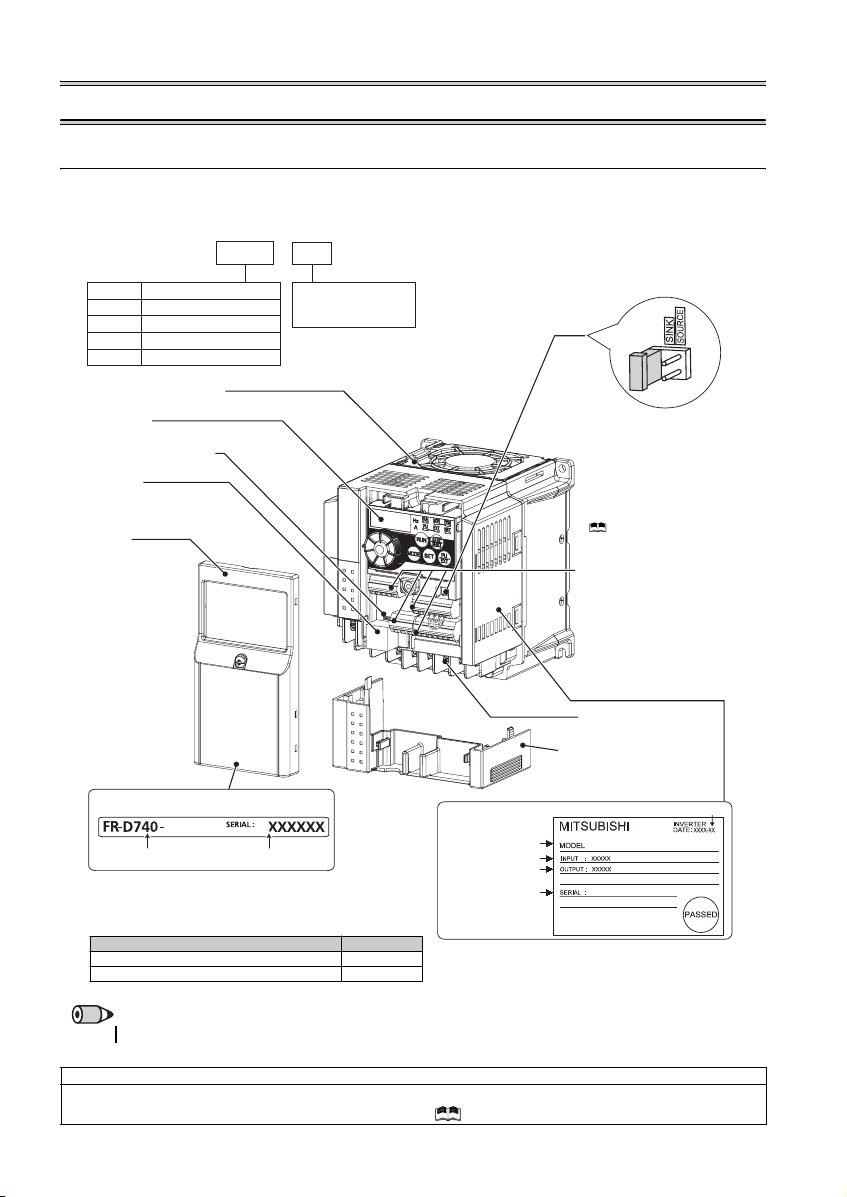
1 OUTLINE
1.1 Product checking and parts identification
Unpack the inverter and check the capacity plate on the front cover and the rating plate on the inverter side face to ensure that
the product agrees with your order and the inverter is intact.
zInverter model
—
FR
D740 1.5
K
Symbol Voltage class
Three-phase 200V class
D720
Three-phase 400V class
D740
Single-phase 200V class
D720S
Single-phase 100V class
D710W
Cooling fan
Operation panel
(Refer to page 2)
Voltage/current input switch
(Refer to page 
PU connector
(Refer to page
Front cover
Refer to the Instru ction
Manual (Applied) for
installation/removal.
The cooling f an is removable .
Represents the
inverter capacity [kW]
Capacity plate
1.5K
Inverter model
• Accessory
· Fan cover fixing screws (M3 × 35mm)
These screws are necessary for compliance with the
EU Directive. (
Serial number
Refer to page 43
Capacity Quantity
1.5K to 3.7K 1
5.5K to 15K 2
)
Rating plate
Inverter model
Input rating
Output rating
Serial number
Control logic switchover jumper
connector
The jumper connector is in the sink
logic (SINK) when shipped from the
factory. Move the jumper connector
to change to the source logic
(SOURCE). Always fit the jumper
connector to the either position.
( Refer to the Inst ruction Manual
(Applied))
Control circuit terminal block
(Refer to page 9)
Main circuit terminal block
(Refer to p age 9)
Combed shaped wiring cover
Refer to the Instruction Manual
(Applied) for installation /removal.
Production year and month
FR-D740-1.5K
REMARKS
·
For how to find the SERIA L number, refer to page 46.
Harmonic suppression guideline (when inverters are used in Japan)
All models of general -purpose inverters used by specific consumers are covered by «Harmonic Su ppression Guidelines for Con sumers
Who Receive High Voltage or Special High Voltage». (For fur ther details, refer to Chapter 3 of the Instruction Manual (Applied).)
1
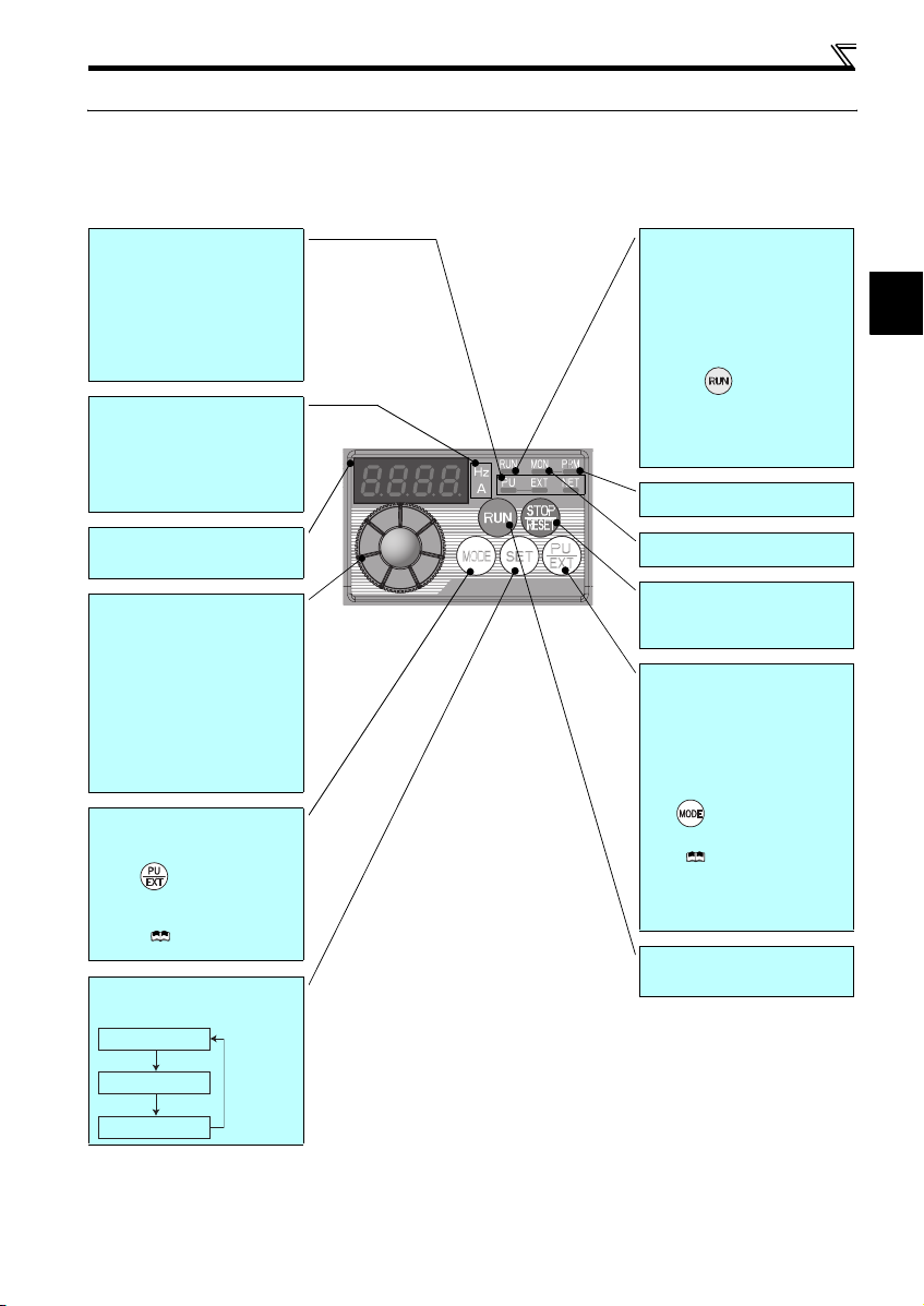
1.2 Operation panel
1.2.1 Names and functions of the operation panel
The operation panel cannot be removed from the inverter.
Operation panel
Operation mode indicator
PU: Lit to indicate P U operation mode.
EXT: Lit to indicate Extern al operation mode.
(Lit at power-ON at initial setting.)
NET: Lit to indicate Network operation mode.
PU, EXT: Lit to indicate External/PU
combined operation mode 1, 2.
These turn OFF whe n command source is
not on oper ation panel.
Unit indicator
Hz: Lit to indicate frequency.
(Flickers when the set frequency
monitor is displayed.)
A: Lit to indicate c urrent.
(Both «Hz» and «A» turn OFF when other
than the above is displayed.)
Monitor (4-digit LED)
Shows th e frequency, paramet er number,
etc.
Setting dial
(Setting dial: Mitsubishi inverter dial)
The setting dial is used to change the
frequency and parameter settings.
Press the setting dial to perform the
following operations:
y To display a set frequency in the
monitor mode
y To display the present setti ng during
calibration
y To display a fault history number in the
faults history mode
Mode switch over
Used to switch among different setting
modes.
Pressing simultaneously changes
the operation mode.
Pressing for a while (2s) can lock
operation. (
Manual (Applied))
Determination of each setting
If pressed during operation, monitor
changes as below:
Running frequency
Refer to the Instru ction
Operating status indicator
Lit or flicker during inverter operation.
* Lit: When the forward rotation operation
is being performed.
Slow flickering (1.4s cycle):
When the reverse rotation operation
is being performed.
Fast flickering (0.2s cycle):
yWhen was pressed or the start
command was given, but the
operation cannot be made.
yWhen the frequency command is less
than the starting frequency.
yWhen the MRS signal is input.
Parameter setting mode indicator
Lit to indicate paramete r setting mode.
Monitor indicator
Lit to indicate monitoring mode.
STOP operation
Used to stop operation commands.
Used to reset a fault when the protective
function (fault) is activated.
Operation mode switchover
Used to switch between the PU and
External operation modes.
To use the External operation mode
(operati on using a separat ely connecte d
frequency setting potentiometer and start
signal), press this key to lig ht up the EXT
indicator.
(Press simultaneously (0.5s), or
change
Pr. 79
mode .)
Manual (Applied))
PU: PU operation mode
EXT: External operation mode
Cancels PU stop also.
Start command
The rotation direction can be selected by
setting Pr. 40.
setting to change to c ombined
( Refer to the Instruction
∗
1
Output current
Output voltage
2
Operation panel
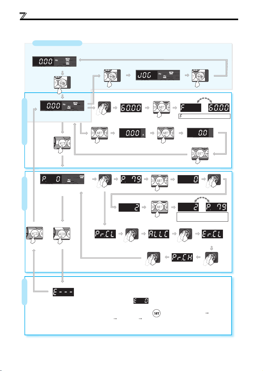
1.2.2 Basic operation (factory setting)
Operation mode switchover
At power-ON (External operation mode)
PU Jog operation mode
(Example)
PU operation mode
(output frequency monitor)
Parameter setting mode
Parameter settingFaults history Monitor/frequency setting
Value change
Output current monitor
Value change
Parameter clear All parameter
[Operation for displaying faults history]
The past eight faults can be displayed using the setting dial.
(The latest fault is ended by «.».)
When no fault history exists, is displayed.
While a fault is displayed:
The display shifts as follows by pressing : Output frequency at the fault
Output current Output voltage Energization time.
(After Energization time, it goes back to a fault display.)
Pressing the setting dial shows the fault history number.
STOP
clear
(Refer to page 35)
and frequency flicker alternately.
Frequency setting has been
written and completed!!
Output voltage monitor
Display the
present setting
(Example)
Parameter and a setting value
flicker alternately.
Parameter write is completed!!
Faults history clear
Initial value
change list
3
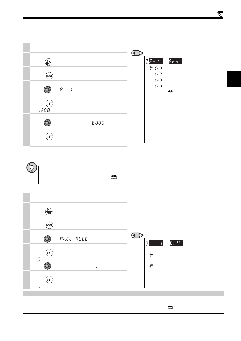
1.2.3 Changing the parameter setting value
Operation example Change the Pr. 1 Maximum frequency setting.
Operation
Screen at power-ON
1.
The monitor display app ears.
Operation mode change
2.
Press to choos e the PU operation mode. PU i ndicator is li t.
Parameter setting mode
3.
Press to choose the parameter sett ing mode.
Selecting the parameter number
4.
Turn until (Pr. 1) appears.
Reading the setting value
Press to read the present set value .
5.
« «(120.0Hz (initial value) ) appears.
Changing the setting value
6.
Turn to c hange the set value to « » (60.00Hz).
Setting the parameter
Press to set.
7.
The parameter number an d the setting value flicker alte rnately.
1.2.4 Parameter clear/all parameter clear
POINT
y Set «1» in Pr.CL Parameter clear or ALLC all parameter clear to initialize parameters. (Parameters are not cleared
when «1» is set in Pr. 77 Parameter write selection.)
y Refer to the extended parameter list of the Instruction Manual (Applied) for parameters cleared with this
operation.
Operation
Screen at power-ON
1.
The monitor display app ears.
Operation mode change
2.
Press to choose the PU operation mode. PU indicator is lit.
Parameter setting mode
3.
Press to choose the parameter sett ing mode.
Selecting Parameter Clear (All Parameter Clear)
4.
Turn until ( ) appe ars.
Selecting the setting value
Press to read the present set value .
5.
» «(initial value) appears.
Turn to c hange it to the set value » «.
Executing Parameter Clear
6.
Press to set.
» » and Pr. CL (ALLC) indications flicker alterna tely.
Setting Description
0 Clear is not executed.
Sets parameters back to th e initial values. (Parame ter clear sets back all paramete rs except calibrati on parameters,
1
terminal function selection parameters to the initial values.) Refer to the parameter list of the Instructi on Manual (Applied) for
availability of parameter clear and all parameter cle ar.
Operation panel
REMARKS
to
appears …..Write disable error
appears
appears …..Calibration error
appears …..Mode designatio n error
(For details, refer to the Inst ruction Manual
(Applied).)
y The number of digits displayed on the ope ration
panel is four. Only the upper four digits of values can
be displayed and set. If the values to be displayed
have five digits or more including decimal places, the
fifth or later numerals cannot be displayed nor set.
(Example) For Pr. 1
When 60Hz is set, 60.00 is d isplayed.
When 120Hz is set, 120.0 is displayed and s econd
decimal place is not displayed nor set.
REMARKS
and
Why?
The inverter is not in the PU operation mode.
(Refer to the step 2. )
PU connector is us ed (when a parameter unit
(FR-PU04/FR-PU07) is us ed).
y Stop the inverter. Parameter clear is unavailable
when the inverter is running, and will cause the write
disable error.
is displayed…Why?
….. Write error during operation
are displayed al ternately …
1
4
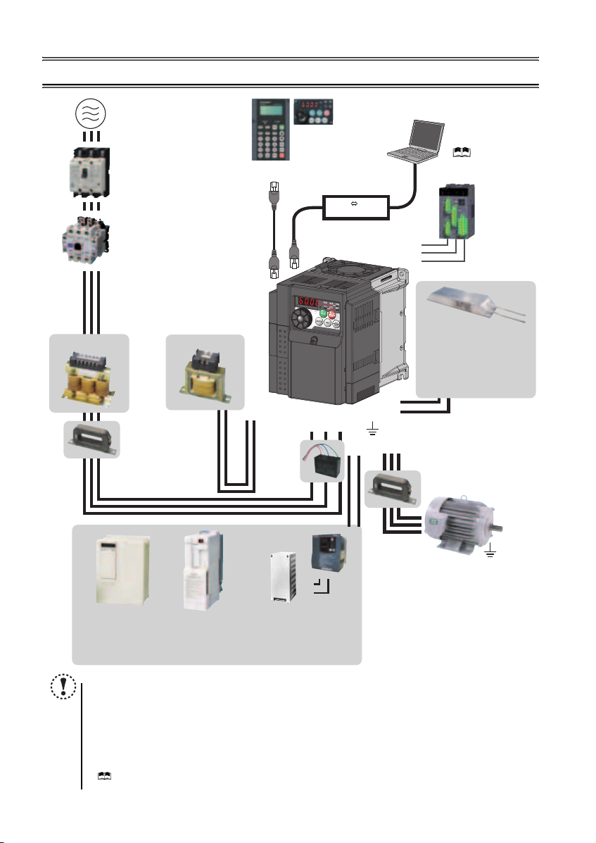
2 INSTALLATION AND WIRING
AC power supply
Use within the permissible power supply
specifications of the inverter. To ensure
safety, use a moulded case circuit breaker,
earth leakage circuit breaker or magnetic
contactor to switch power ON/OFF.
(Refer to page 40)
Moulded case circuit breaker
(MCCB) or earth leakage circuit
breaker (ELB), fuse
The breaker must be selected carefully
since an in-rush current flows in the
inverter at power on.
(Refer to page 6)
Magnetic contactor (MC)
Install the magnetic contactor to ensure
safety. Do not use this magnetic contactor
to start and stop the inverter. Doing so will
cause the inverter life to be shortened.
(Refer to page 6)
Reactor (FR-HAL, FR-HEL option)
Reactors (option) must be used when
power harmonics measures are taken,
the power factor is to be improved or the
inverter is installed near a large power
supply system (500kVA or more). The
inverter may be damaged if you do not
use reactors. Select the reactor according
to the model. Remove the jumpers across
AC reactor (FR-HAL)
* Filterpack (FR-BFP2), which contains DC reactor and noise filter in one package, is also available.
terminals P/+ and P1 to connect the DC reactor.
Install a noise filter (ferrite core)
to reduce the electromagnetic
noise generated from the
inverter. Effective in the range
from about 1MHz to 10MHz.
When more wires are passed
through, a more effective result
can be obtained. A wire should
be wound four turns or more.
High power factor
converter (FR-HC)
Power supply harmonics
can be greatly suppressed.
Install this as required.
DC reactor (FR-HEL) *
Noise filter (ferrite core) *
(FR-BSF01, FR-BLF)
Power regeneration
common converter
(FR-CV)
Great braking capability
is obtained.
Install this as required.
Parameter unit
(FR-PU07)
P/+
P1
Resistor unit (FR-BR)
Discharging resistor (GZG, GRZG)
The regenerative braking capability
of the inverter can be exhibited fully.
Install this as required.
NOTE
y
The life of the inverter is influenced by surrounding air temperature. The surrounding air temperature should be as low as
possible within the permissible range. This must be noted especially when the inverter is installed in an enclosure.
y Wrong wiring might lead to damage of the inverter. The control signal lines must be kept fully away from the main
circuit to protect them f rom noise. (Refer to page
y Do not install a power factor correction capacitor, surge suppressor or noise filter (capacitor) on the inverter output
side. This will cause the inverter to trip or the capacitor and surge suppressor to be damaged. If any of the above
devices are connected, immediate ly remove them.
y Electromagnetic wave interference
The input/output (main circuit) of the inverter includes high frequency components, which may interfere with the
communication device s (such as AM radios) used near the inverter. In this case, install the FR-BIF optiona l
(capacitor)
(for use in the input side only) or FR-BSF01 or FR-BLF
(
Refer to Chapter 3 of the Instructio n Manual (Applied)
y Refer to the Instruction Manual of each option and peripheral devices for details of peripheral devices.
Enclosure surface operation
panel (FR-PA07)
By connecting the connection cable
(FR-CB2) to the PU connector,
operation can be performed from
FR-PU07, FR-PA07.
Inverter (FR-D700)
Brake unit
(FR-BU2)
R/L1 S/L2T/L3
P/+
PR
Noise filter
(capacitor) *
(FR-BIF)
Reduces the
radio noise.
).
RS-485 RS-232C
PR
P/+
RS-232C — RS-485 converter is
required when connecting to PC
with RS-232C interface.
( Refer to the
Instruction Manual (Applied))
Converter
S1
S2
SC
P/+
PR
Noise filter (ferrite core)
Earth (Ground)
UW
N/-
P/+
Devices connected to the output
Do not install a power factor correction capacitor,
surge suppressor or noise filter (capacitor) on the output
side of the inverter. When installing a moulded case
circuit breaker on the output side of the inverter,
contact each manufacturer for selection of the
moulded case circuit breaker.
Earth (Ground)
To prevent an electric shock, always earth (ground)
the motor and inverter. For reduction of induction noise
from the power line of the inverter, it is recommended
to wire the earth (ground) cable by returning it to the
earth (ground) terminal of the inverter.
(FR-BSF01, FR-BLF)
Install a noise filter (ferrite core)
to reduce the electromagnetic
V
noise generated from the inverter.
Effective in the range from about
1MHz to 10MHz. A wire should be
wound four turns at a maximum.
noise filter (ferrite core)
Approved safety
relay module
Required for
compliance with
safety standard.
Brake resistor (FR-ABR,
MRS type, MYS type)
Braking capability can be
improved. (0.4K o r higher)
Always install a thermal relay
when using a brake resistor
whose capacity is 11K or higher.
(Refer to page 17)
to minimize interference.
Motor
Earth (Ground)
(Refer to page 7)
noise filter
5
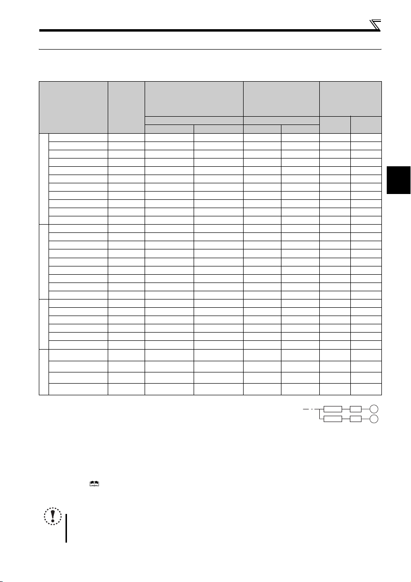
Peripheral devices
2.1 Peripheral devices
Check the inverter model of the inverter you purchased. Appropriate peripheral devices must be selected according to the capacity.
Refer to the following list and prepare appropriate peripheral devices.
Moulded Case Circuit Breaker
(MCCB) ∗1
(ELB) ∗2
(NF or NV type)
Reactor connection Reactor connection
Inverter Model
Motor
Output
(kW)
or Earth Leakage Circuit Breaker
without with without with
FR-D720-0.1K 0.1 5A 5A S-N10 S-N10 0.4K ∗5 0.4K ∗5
FR-D720-0.2K 0.2 5A 5A S-N10 S-N10 0.4K ∗5 0.4K ∗5
FR-D720-0.4K 0.4 5A 5A S-N10 S-N10 0.4K 0.4K
FR-D720-0.75K 0.75 10A 5A S-N10 S-N10 0.75K 0.75K
FR-D720-1.5K 1.5 15A 10A S-N10 S-N10 1.5K 1.5K
FR-D720-2.2K 2.2 20A 15A S-N10 S-N10 2.2K 2.2K
FR-D720-3.7K 3.7 30A 30A S-N20, S-N21 S-N10 3.7K 3.7K
FR-D720-5.5K 5.5 50A 40A S-N20, S-N21 S-N20, S-N21 5.5K 5.5K
Three-Phase 200V
FR-D720-7.5K 7.5 60A 50A S-N25 S-N20, S-N21 7.5K 7. 5K
FR-D720-11K 11 75A 75A S-N35 S-N35 11K 11K
FR-D720-15K 15 125A 100A S-N50 S-N50 15K 15K
FR-D740-0.4K 0.4 5A 5A S-N10 S-N10 H0.4K H0.4K
FR-D740-0.75K 0.75 5A 5A S-N10 S-N 10 H0.75K H0.75K
FR-D740-1.5K 1.5 10A 10A S-N10 S-N10 H1.5K H1.5K
FR-D740-2.2K 2.2 15A 10A S-N10 S-N10 H2.2K H2.2K
FR-D740-3.7K 3.7 20A 15A S-N10 S-N10 H3.7K H3.7K
FR-D740-5.5K 5.5 30A 20A S-N20, S-N21 S-N11, S-N12 H5.5K H5.5K
FR-D740-7.5K 7.5 30A 30A S-N20, S-N21 S-N20, S-N21 H7.5K H7.5K
Three-Phase 400V
FR-D740-11K 11 50A 40A S-N20, S-N21 S-N20, S-N21 H11K H 11K
FR-D740-15K 15 6 0A 50A S-N25 S-N20, S-N21 H15K H15K
FR-D720S-0.1K 0.1 5A 5A S-N10 S-N10 0 .4K ∗5 0.4K ∗5
FR-D720S-0.2K 0.2 5A 5A S-N10 S-N10 0 .4K ∗5 0.4K ∗5
FR-D720S-0.4K 0.4 10A 10A S-N10 S-N10 0.75K ∗5 0.75K ∗5
FR-D720S-0.75K 0.75 15A 10A S-N10 S-N 10 1.5K ∗5 1.5K ∗5
FR-D720S-1.5K 1.5 20A 20A S-N10 S-N10 2 .2K ∗5 2.2K ∗5
FR-D720S-2.2K 2.2 40A 30A S-N20, S-N21 S-N10 3.7K ∗5 3.7K ∗5
Single-Phase 200V
FR-D710W-0.1K 0.1 10A 5A S-N10 S-N10
FR-D710W-0.2K 0.2 10A 10A S-N10 S-N10 1 .5K ∗4, ∗5 — ∗6
FR-D710W-0.4K 0.4 15A 15A S-N10 S-N10 2 .2K ∗4, ∗5 — ∗6
FR-D710W-0.75K 0.75 30A 20A S-N10 S -N10 3.7K ∗4, ∗5 — ∗6
Single-Phase 100V
∗1 ySelect a MCCB according to the power supply capacity.
yInstall one MCCB per inverter.
∗2 For the use in the United States or Canada, select an UL and cUL certified fuse with Class T fuse equivalent cut-off
speed or faster with the appropriate rating for branch circuit protection. Alternatively, select a UL489 molded case circuit breaker (MCCB). (Refer to page 46)
∗3 Magnetic contactor is selected based on the AC-1 class. The electrical durability of magnetic contactor is 500,000 times. When the magnetic contactor is
used for emergency stop during motor driving, the electrical durability is 25 times.
If using an MC for emergency stop during motor driving, select an MC regarding the inverter input side current as JEM1038-AC-3 class rated current. When
using an MC on the inverter output side for commercial-power supply operation switching using a general purpose motor, select an MC regarding the motor
rated current as JEM1038-AC-3 class rated current.
∗4 When connecting a single-phase 100V power input model to a power transformer (50kVA or more), install an AC reactor (FR-HAL) so that the performance
is more reliable. ( Refer to Chapter 3 of the Instruction Manual (Applied))
∗5 The power factor may be slightly lower.
∗6 Single-phase 100V power input model is not compatible with DC reactor.
NOTE
y When the inverter capacity is larger than the motor capacity, select an MCCB and a magnetic contactor according to the inverter model,
and cable and reactor according to the motor output.
y When the breaker on the inverter input side trips, check for the wiring fault (short circuit), damage to internal parts of the inverter, etc.
Identify the cause of the trip, then remove the cause and power ON the breaker.
Magnetic Contactor (MC)
∗3
Reactor
FR-HAL FR-HEL
0.75K
∗4, ∗5
— ∗6
MCCB INV
MCCB INV
IM
IM
2
6
Installation of the inverters and precautions
2.2 Installation of the inverters and precautions
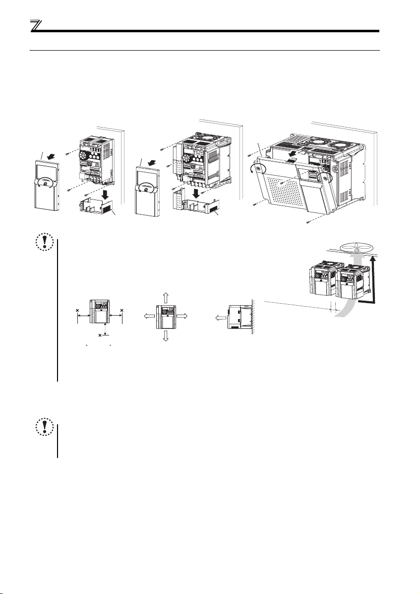
(1) Installation of the inverter
Enclosure surface mounting
Remove the front cover and wiring cover to mount the inverter to the surface. (Remove the covers in the directions of the
arrows.)
FR-D720-0.1K to 0.75K
FR-D720S-0.1K to 0.75K
FR-D710W-0.1K to 0.4K
Front cover
NOTE
y When encasing multiple inverters, install them in paral lel as a cooling
measure.
y Install the inverter vertically.
y For heat dissipation and maintenance, allow minimum clearance shown
in the figures below fro m the inverter to the other devices and to the
inner surface of the enclosure.
5cm
Measurement
position
-10 C to +50 C
(non-freezing)
∗1 Allow 5cm or more clearance for 5.5K or higher.
∗2 When using the inverters at the surrounding air temperature of 40°C or less, the inverters can be installed without any clearance between
them (0cm clearance).
5cm
(2) Environment
Before installation, che ck that the environment meets the specifications on page 41.
Note
y Install the inverter on a strong surface securely and vertically with bolts.
y Leave enough clearances and take cooling measures.
y Avoid places where the inverter is subjected to direct sunlight, high temperature and high humidity.
y Install the inverter on a nonflammable wall surface.
FR-D720-1.5K to 3.7K
FR-D740-0.4K to 3.7K
FR-D720S-1.5K, 2.2K
FR-D710W-0.75K
Front cover
Wiring cover Wiring cover
Measurement
position
5cm
1cm or
more
∗1, ∗2
10cm or more
1cm or
∗1, ∗2
more
10cm or more
1cm or
more
∗1
FR-D720-5.5K to 15K
FR-D740-5.5K to 15K
Front cover
Refer to the clearances below.
7
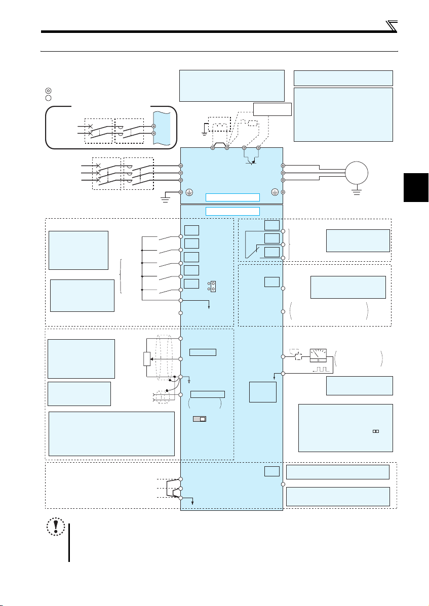
2.3 Wiring
2.3.1 Terminal connection diagram
Sink logic
Main circuit terminal
Control circuit terminal
Single-phase power input
Single-phase
AC power
supply
Three-phase
AC power
supply
Control input signals (No voltage input allowed)
The function of these
terminals can be
changed to the reset
signal, etc. with the input
terminal assignment
(Pr. 178 to Pr. 182)
*2 When using terminals PC-
SD as a 24VDC power
supply, take care not to
short across terminals
PC and SD.
Frequency setting signals (Analog)
*3 Terminal input specifications
can be changed by analog
input specifications
switchover (Pr. 73).
Terminal 10 and terminal 2
are used as PTC input
terminal (Pr. 561).
*4 It is recommended to
use 2W1kΩ when the
frequency setting signal
is changed frequently.
*5 Terminal input specifications can be changed by analog
input specifications switchover (Pr. 267). Set the
voltage/current input switch in the «V» position to select
voltage input (0 to 5V/0 to10V) and «I» (initial value) to
select current input (4 to 20mA).
To use terminal 4 (initial setting is current input), set «4»
in any of Pr.178 to Pr.182 (input terminal function
selection) to assign the function, and turn ON AU signal.
MCCB MC
MCCB MC
Earth
(Ground)
Forward
rotation start
Reverse
rotation start
High
.
Multi-speed selection
speed
Middle
speed
Low
speed
Contact input common
(Common for external power supply transistor)
24VDC power supply
3
Frequency
setting
potentiometer
1/2W1kΩ
*4
1
Terminal 4
(+)
input
(-)
(Current
input)
R/L1
S/L2
(Ground)
2
*
1. DC reactor (FR-HEL)
When connecting a DC reactor, remove the
jumper across P1 and P/+.
Single-phase 100V power input model is not
compatible with DC reactor.
Earth
R/L1
S/L2
T/L3
Jumper
*1
P1 P/+
*6
R
*7
PR
N/-
Main circuit
Control circuit
STF
STR
RH
RM
RL
SD
PC
10(+5V)
2 0 to 5VDC
(0 to 10VDC)
5(Analog common)
4 4 to 20mADC
0 to 5VDC
0 to 10VDC
VI
Voltage/current
input switch
*2
SOURCE
*5
*3
SINK
*5
connector
Brake unit
(Option)
RUN
PU
*9
*6 Terminal P1 is not available for single-
phase 100V power input model.
*7 Brake resistor (FR-ABR, MRS type, MYS
type)
Install a thermal relay to prevent an
overheat and burnout of the brake resistor.
Always install a thermal relay when using
a brake resistor whose capacity is 11K or
higher.
(The brake resistor can not be connected
to the 0.1K and 0.2K.)
U
V
W
C
B
A
Relay output
(Fault output)
Relay output
Open collector output
Terminal functions vary by
Pr. 190 RUN terminal function
Running
selection
Open collector output common
SE
Sink/source common
Calibration resistor
+
—
FM
*8
SD
*9 Operation and parameter setting can be
done from the parameter unit (FRPU07) and the enclosure surface
operation panel (FR-PA07).
(Use the option cable (FR-CB2 ).)
RS-485 communication can be utilized
from a personal computer and other
devices.
Wiring
Motor
IM
Earth (Ground)
Terminal functions vary
by Pr. 192 A,B,C terminal
function selection
Indicator
(Frequency meter, etc.)
Moving-coil type
1mA full-scale
*8 It is not necessary when
calibrating the indicator
from the operation panel.
2
Safety stop signal
Safe stop input (Channel 1)
Safe stop input (Channel 2)
Safe stop input common
NOTE
y To prevent a malfunction caus ed by noise, separate the signal c ables more than 10cm from the power cables. Also
separate the main circuit w ire of the input side and t he output side.
y After wiring, wire off cuts must not be left in the inverter.
Wire offcuts can cause an alarm, failure or malfunction. Always keep the inverter clean. When drilling mounting holes
in an enclosure etc., take ca re not to allow chips and other foreign matter to enter the inverter.
y The output of the single-phase power input model is three-phase 200V.
Shorting
wire
Terminal functions vary by Pr. 197 SO
S1
S2
SC
SO
terminal function selection
Safety monitor output *10
*10 Common terminal of terminal SO is
terminal SC. (Connected to terminal SD
inside of the inverter.)
8
Wiring
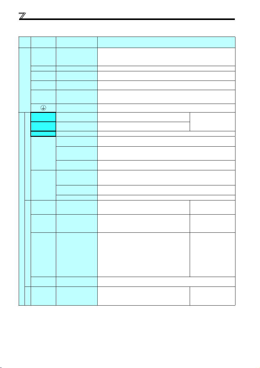
2.3.2 Terminal specifications
Terminal
Typ e
Symbol
R/L1, S/L2,
T/L3
U, V, W Inverter output
P/+, PR Brake resistor connection
P/+, N/- Brake unit connection
Main circuit terminal
P/+, P1 ∗ DC reactor connection
STF Forward rotation start
STR Reverse rotation start
RH, RM, RL Multi-speed selection
SD
Contact input
PC
10
2
Control circuit terminal/Inpu t signal
4
Frequency setting
5
10
2
Thermistor
Terminal Name Terminal Specification
∗
AC power input
Earth (Ground)
Contact input common
(sink) (initial setting)
External transistor
common (source)
24VDC power supply
common
External transistor
common (sink)
(initial setting)
Contact input common
(source)
24VDC power supply
Frequency setting power
supply
Frequency setting
(voltage)
Frequency setting
(current)
Frequency setting
common
PTC thermistor input
Connect to the commercial power supply.
Do not connect anything to these terminals when using the high power factor converter (FRHC) or power regeneration common converter (FR-CV).
* When using single-phase power inpu t, terminal s are R/L1 and S/L2.
Connect a three-phase squirrel-cage motor.
Connect a brake resistor (FR-ABR, MRS type, MYS type) across terminals P/+ and PR.
(The brake resistor can not be connected to the 0.1K and 0.2K.)
Connect the brake unit (FR-BU2), power regeneration common converter (FR-CV) or high
power factor converter (FR-HC).
Remove the jumper across terminals P/+ and P1 and connect a DC reactor. (Single-phase
100V power input model is not compatible with the DC reactor.)
* Terminal P1 is not available for single-phase 100V power input model.
For earthing (grounding) the inverter chassis. Must be earthed (grounded).
Turn ON the STF signal to start forward rotati on and turn it OFF
to stop.
Turn ON the STR signal to start reverse rotation and turn it
OFF to stop.
Multi-speed can be selected according to the combination of RH, RM and RL signals.
Common terminal for contact input terminal (sink logic) and terminal FM.
Connect this terminal to the power supply common terminal of a transistor output (open
collector output) device, such as a programmable controller, in the source logic to avoid
malfunction by undesirable current.
Common output terminal for 24VDC 0.1A power supply (PC terminal).
Isolated from terminals 5 and SE.
Connect this terminal to the power supply common terminal of a transistor output (open
collector output) device, such as a programmable controller, in the sink logic to avoid
malfunction by undesirable current.
Common terminal for contact input terminal (source logic).
Can be used as 24VDC 0.1A power supply.
Used as power supply when connecting potentiometer for
frequency setting (speed setting) from outside of the inverter.
Inputting 0 to 5VDC (or 0 to 10V) provides the maximum output
frequency at 5V (10V) and makes input and output
proportional. Use Pr. 73 to switch between input 0 to 5VDC
input (initial setting) and 0 to 10VDC.
Inputting 4 to 20mADC (or 0 to 5V, 0 to 10V) provides the
maximum output frequency at 20mA and makes input and
output proportional. This input signal is valid only when the AU
signal is ON (terminal 2 input is invalid). To use terminal 4
(initial setting is current input), set «4» in any of Pr.178 to Pr.182
(input terminal function selecti on) to assign the function, and turn
ON AU signal.
Use Pr. 267 to switch among input 4 to 20mA (initial setting), 0
to 5VDC and 0 to 10VDC. Set the voltage/current input switch
in the «V» posit ion to select volta ge input (0 to 5V/0 to 10V).
Frequency setting signal (terminal 2, 4) common terminal. Do not earth (ground).
For connecting PTC thermistor output.
When PTC thermistor protection is valid (Pr. 561 ≠ «9999»),
terminal 2 is not available for frequency setting.
When the STF and STR
signals are turned ON
simultaneously, the stop
command is given.
5VDC
permissible load current
10mA
Input resistance10kΩ ± 1kΩ
Permissible maximum voltage
20VDC
Current input:
Input resistance 249Ω ± 5Ω
Maximum permissible current
30mA
Voltage input:
Input resistance10kΩ ± 1kΩ
Permissible maximum voltage
20VDC
Adaptive PTC th ermistor
specification
Heat detection resistance :
500Ω to 30kΩ (Set by Pr. 561)
9
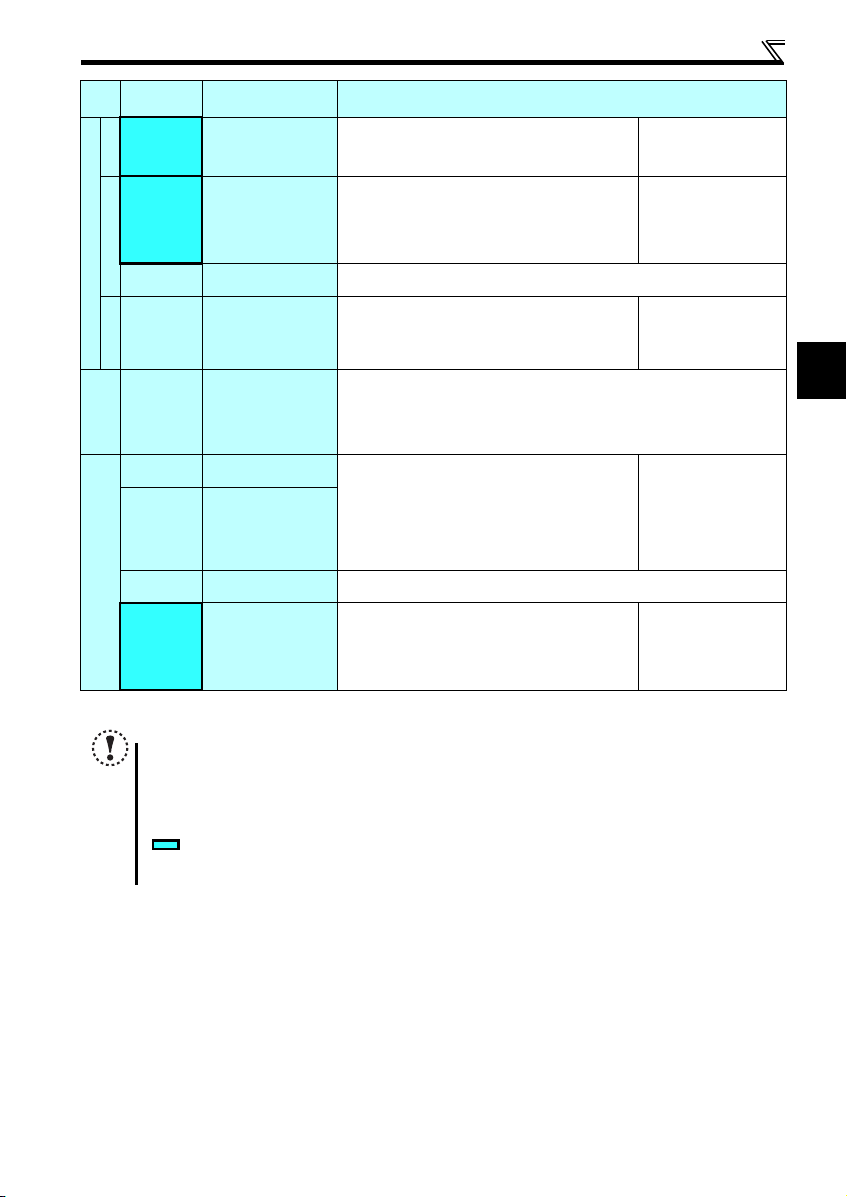
Wiring
Ter min al
Typ e
Symbol
A, B, C
Relay
RUN Inverter running
Open collector
SE
Control circuit terminal/Outp ut signal
FM For meter
Pulse
— PU co nnector
Communication
S1
S2
SC
Safety stop function *
SO
* For more details, refer to the Safety stop function instruction manual (BCN-A211508-000). (Please contact your sales representative for the manual.)
NOTE
y To change the input specification for terminal 4, set Pr. 267 and the voltage/current input switch correctly, then input
the analog signal relevant to the setting. Applying a voltage with voltage/current input switch in «I» position (current
input is selected) or a current with switch in «V» position (voltage input is selected) could cause component damage
to the inverter or analog circuit of output devices.
y Connecting the power supply to the inverter output terminals (U, V, W) will damage the inverter. Do not per form such
wiring.
y indicates that terminal functions can be selected using Pr. 178 to Pr. 182, Pr. 190, Pr. 192, Pr. 197 (I/O terminal
function selection).
y The terminal names and functions shown here are the initial settings.
Terminal Name Terminal Specification
Relay output
(fault output)
Open collector output
common
Safety stop input
(Channel 1)
Safety stop input
(Channel 2)
Safety stop input terminal
common
Safety monitor output
(open collector output)
1 changeover contact output indicates that the inverter
protective function has activated and the output stopped.
Fault: discontin uity across B-C ( continuity across A -C),
Normal: continuity across B-C (discontinuity across A-C)
Switched Low when the inverter output frequency is equal to or
higher than the starting frequency (initial value 0.5Hz).
Switched High during stop or DC injection brake operation.
(Low is when the open collector output transistor is ON
(conducts). High is when the transistor is OFF (does not
conduct).)
Common terminal of terminal RUN.
Used to output a selected monitored item (such as Output
frequency) among several monitored items.
(Not output during inverter reset.)
The output signal is proportional to the magnitude of the
corresponding monitored item.
With the PU connector, communication can be established through RS-485.
yConforming standard: EIA-485 (RS-485)
yTransmission format: Multidrop link
yCommunication speed: 4800 to 38400bps
yOverall length: 500m
Terminals S1 and S2 are for safety stop in put signals used with
the safety relay module. Terminals S1 and S2 are used
simultaneously (dual channel). Inverter output is shut off by
shortening/opening across terminals S1 and SC and across S2
and SC. In the initial status, term inals S1 and S2 are shorted
with terminal SC by shortening wire.
Remove the shortening wire and connect the safety relay
module when using the safety stop function.
Common terminal for terminals S1, S2 and SO. Connected to terminal SD inside of the
inverter.
The signal ind icates the stat us of safety stop i nput.
Low indicates safe state, and High indicates drive enabled or
fault detected.
(Low is when the open collector output transistor is ON
(conducts). High is when the transistor is OFF (does not
conduct).)
Contact capacity:230VAC
0.3A (power factor =0.4)
30VDC 0.3A
Permissible load 24VDC
(maximum 27VDC) 0.1A
(a voltage drop is 3.4V
maximum when the signal is
ON)
Permissible load current 1mA
1440 pulses/s at 60Hz
Input resistance 4.7kΩ
Voltage when contacts are
open
21 to 26VDC
When contacts are shortcircuited
4 to 6mADC
Permissible load 24VDC
(maximum 27VDC) 0.1A
(a voltage drop is 3.4V
maximum when the signal is
ON)
2
10
Wiring
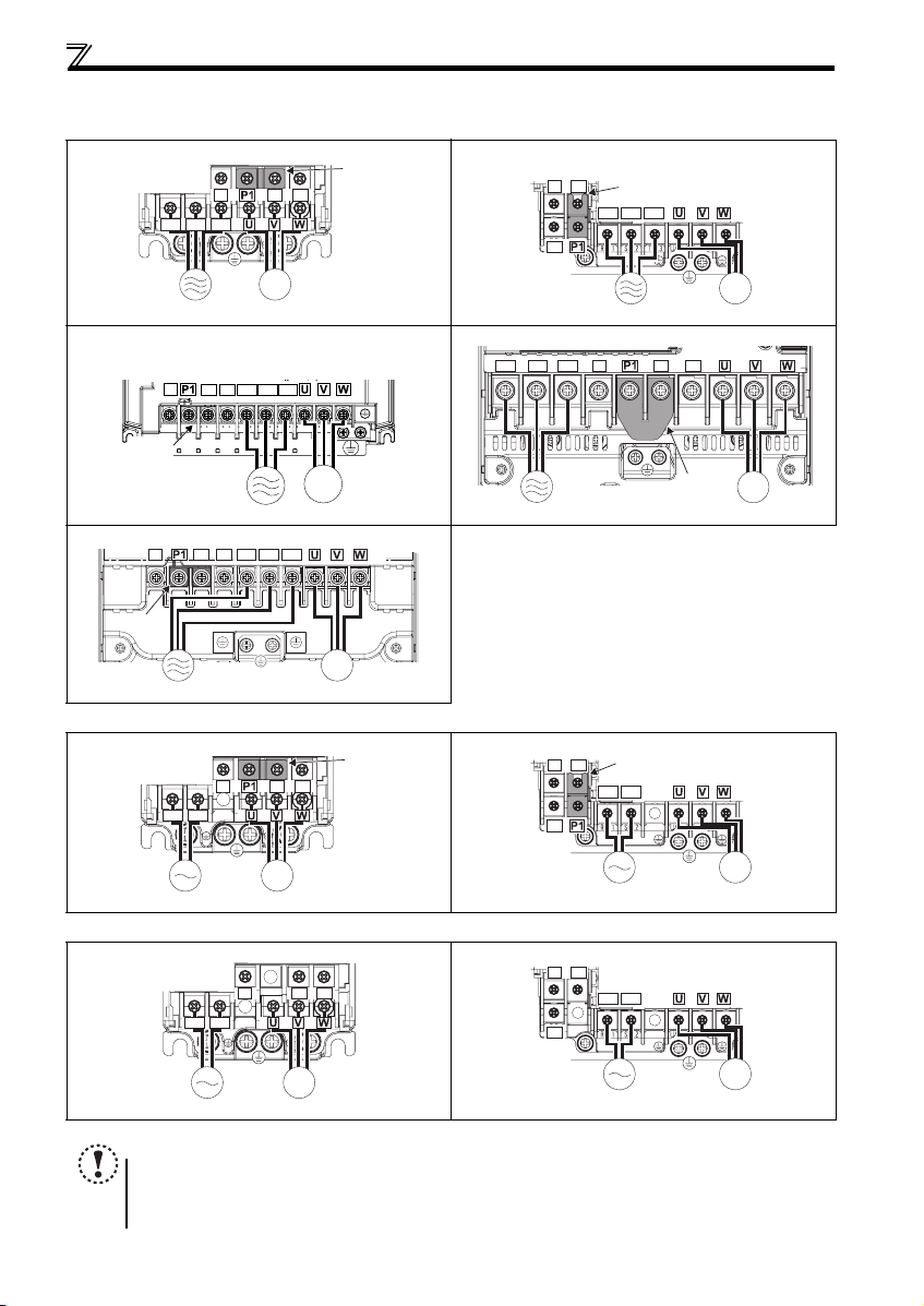
2.3.3 Terminal arrangement of the main circuit terminal, power supply and the motor wiring
zThree-phase 200V/400V class
FR-D720-0.1K to 0.75K FR-D720-1.5K to 3.7K
N/-
P/+ PR
R/L1 S/L2 T/L3
Jumpe
FR-D740-0.4K to 3.7K
N/-
PR
P/+
R/L1 S/L2 T/L3
Jumper
IM
MotorPower supply
FR-D720-5.5K, 7.5K
FR-D740-5.5K, 7.5K
N/-
Jumper
P/+ PR
R/L1 S/L2 T/L3
FR-D720-11K, 15K
R/L1 S/L2 T/L3
IM
FR-D740-11K, 15K
N/-
Jumper
Power supply
zSingle-phase 200V class
FR-D720S-0.1K to 0 .75K FR-D720S-1.5K, 2.2K
R/L1 S/L2
zSingle-phase 100V class
FR-D710W-0.1K to 0.4K FR-D710W-0.75K
P/+
N/-
R/L1 S/L2
PR
Power supply Motor
R/L1 S/L2 T/L3
P/+ PR
IM
MotorPower supply
N/-
P/+ PR
IM
Motor
Jumpe
N/-
PR
N/-
PR
Power supply
N/-
P/+
R/L1 S/L2
P/+
R/L1 S/L2
Jumper
P/+
PR
Jumper
IM
Motor
IM
MotorPower supply
IM
MotorPower supply
IM
MotorPower supply
NOTE
y Make sure the power cables are connected to the R/L1, S/L2, T/L3. (Phase need not be matched.) Never connect the
power cable to the U, V, W of the inverter. Doing so w ill damage the inverter.
y Connect the moto r to U, V, W. Turning ON the forward ro tation switch (signal) at t his time rotates the motor
counterclockwise when viewed from the load shaft.
11
IM
MotorPower supply
Wiring
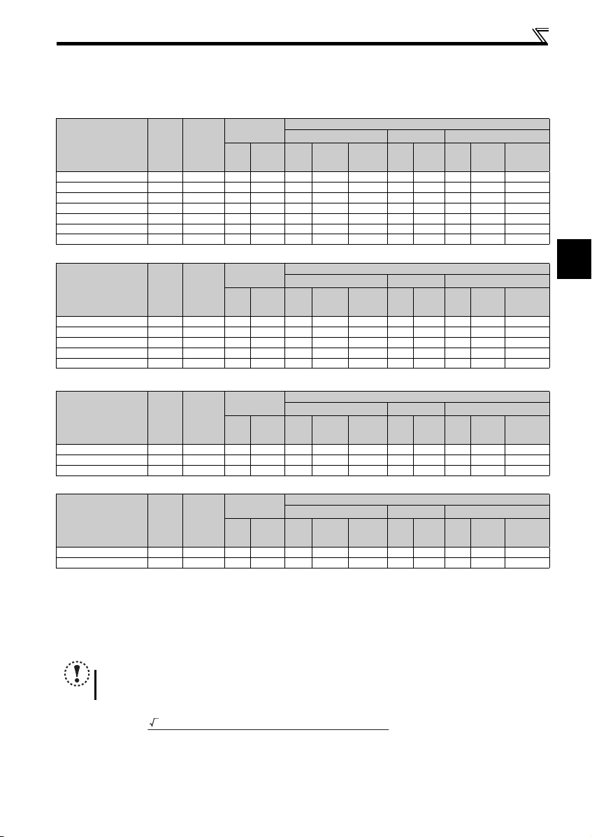
(1) Cable sizes etc., of the main control circuit terminals and earth (ground) terminals
Select the recommended cable size to ensure that a voltage drop will be 2% or less.
If the wiring distance is long between the inverter and motor, a main circuit cable voltage drop will cause the motor torque to
decrease especially at the output of a low frequency.
The following table indicates a selection example for the wiring length of 20m.
Three-phase 200V class (when input power supply is 220V)
N·m
Crimping
Terminal
R/L1
S/L2
T/L3
HIV Cables, etc. (mm2) ∗1
R/L1
U, V, W
S/L2
T/L3
U, V, W
Earthing
(grounding)
Ter mi nal
Applicable Inverter
Model
FR-D720-0.1K to 0.75K M3.5 1.2 2-3.5 2-3.5 2 2 2 14 14 2.5 2.5 2.5
FR-D720-1.5K, 2.2K M4 1.5 2-4 2-4 2 2 2 14 14 2.5 2.5 2.5
FR-D720-3.7K M4 1.5 5.5-4 5.5 -4 3.5 3.5 3.5 12 12 4 4 4
FR-D720-5.5K M5 2.5 5.5-5 5.5 -5 5.5 5.5 5.5 10 10 6 6 6
FR-D720-7.5K M5 2.5 14-5 8- 5 14 8 5.5 6 8 16 1 0 6
FR-D720-11K M5 2.5 14-5 14-5 14 14 14 6 6 1 6 16 16
FR-D720-15K M6 (M5) 4.4 22-6 22-6 22 22 14 4 4 25 25 16
Screw
Size ∗4
Tightening
Tor que
Three-phase 400V class (when input power supply is 440V)
N·m
Crimping
Terminal
R/L1
S/L2
T/L3
HIV Cables, etc. (mm2) ∗1
R/L1
U, V, W
S/L2
T/L3
U, V, W
Earthing
(grounding)
Ter mi nal
Applicable Inverter
Model
FR-D740-0.4K to 3.7K M4 1.5 2-4 2-4 2 2 2 14 14 2.5 2.5 2.5
FR-D740-5.5K M4 1.5 5.5-4 2-4 3.5 2 3.5 12 14 4 2.5 4
FR-D740-7.5K M4 1.5 5.5-4 5.5 -4 3.5 3.5 3.5 12 12 4 4 4
FR-D740-11K M4 1.5 5.5-4 5.5-4 5.5 5.5 8 10 10 6 6 10
FR-D740-15K M5 2.5 8-5 8-5 8 8 8 8 8 10 10 10
Screw
Size ∗4
Tightening
Tor que
Single-phase 200V class (when input power supply is 220V)
N·m
Crimping
Terminal
R/L1
S/L2
HIV Cables, etc. (mm2) ∗1
R/L1
U, V, W
S/L2
U, V, W
Earthing
(grounding)
Ter mi nal
Applicable Inverter
Model
FR-D720S-0.1K to 0.75K M3.5 1.2 2-3.5 2-3.5 2 2 2 14 14 2.5 2.5 2.5
FR-D720S-1.5K M4 1.5 2-4 2-4 2 2 2 14 14 2.5 2.5 2.5
FR-D720S-2.2K M4 1.5 5 .5-4 2-4 3 .5 2 3.5 12 14 4 2.5 4
Screw
Size ∗4
Tightening
Tor que
Single-phase 100V class (when input power supply is 100V)
N·m
Crimping
Terminal
R/L1
S/L2
HIV Cables, etc. (mm2) ∗1
R/L1
U, V, W
S/L2
U, V, W
Earthing
(grounding)
Ter mi nal
Applicable Inverter
Model
FR-D710W-0.1K to 0.4K M3.5 1.2 2- 3.5 2-3.5 2 2 2 14 14 2.5 2.5 2 .5
FR-D710W-0.75K M4 1.5 5.5-4 2-4 3.5 2 2 12 14 4 2.5 2 .5
∗1 The cable size is that of the cable (HIV cable (600V class 2 vinyl-insulated cable) etc.) with continuous maximum permissible temperature of 75°C. Assumes
that the surrounding air temperature is 50°C or less and the wiring distance is 20m or less.
∗2 The recommended cable size is that of the cable (THHW cable) with continuous maximum permissible temperature of 75°C. Assumes that the surrounding
air temperature is 40°C or less and the wiring distance is 20m or less. (Selection example for use mainly in the United States.)
∗3 The recommended cable size is that of the cable (PVC cable) with continuous maximum permissible temperature of 70°C. Assumes that the surrounding air
temperature is 40°C or less and the wiring distance is 20m or less. (Selection example for use mainly in Europe.)
∗4 The terminal screw size indicates the terminal size for R/L1, S/L2, T/L3, U, V, W, PR, P/+, N/-, P1 and a screw for earthing (grounding).
Screw size for earthing (grounding) the FR-D720-15K is indicated in parentheses.
For single-phase power input, the terminal screw size indicates the size of terminal screw for R/L1, S/L2, U, V, W, PR, P/+, N/-, P1 and a screw for earthing
(grounding).
Screw
Size ∗4
Tightening
Tor que
NOTE
y
Tighten the terminal screw to the specified torque. A screw that has been tightened too loosely can cause a short circuit or
malfunction. A screw that has been tightened too tightly can cause a short circuit or malfunction due to the unit breakage.
y Use crimping terminals with insulation sleeve to wire the power supply and motor.
The line voltage drop can be calculated by the following formula:
Line voltage drop [V]=
Use a larger diameter cable when the wiring distance is long or when it is desired to decrease the voltage drop (torque
reduction) in the low speed range.
3 × wire resistance[mΩ/m] × wiring distance[m] × current[A]
1000
cable
cable
cable
cable
Cable Size
AWG ∗2
R/L1
S/L2
U, V, W
T/L3
Cable Size
AWG ∗2
R/L1
S/L2
U, V, W
T/L3
Cable Size
AWG ∗2
R/L1
U, V, W
S/L2
Cable Size
AWG ∗2
R/L1
U, V, W
S/L2
PVC Cables, etc. (mm2) ∗3
R/L1
S/L2
T/L3
PVC Cables, etc. (mm2) ∗3
R/L1
S/L2
T/L3
PVC Cables, etc. (mm2) ∗3
R/L1
S/L2
PVC Cables, etc. (mm2) ∗3
R/L1
S/L2
U, V, W
U, V, W
U, V, W
U, V, W
Earthing
(grounding)
cable
Earthing
(grounding)
cable
Earthing
(grounding)
cable
Earthing
(grounding)
cable
2
12
Wiring
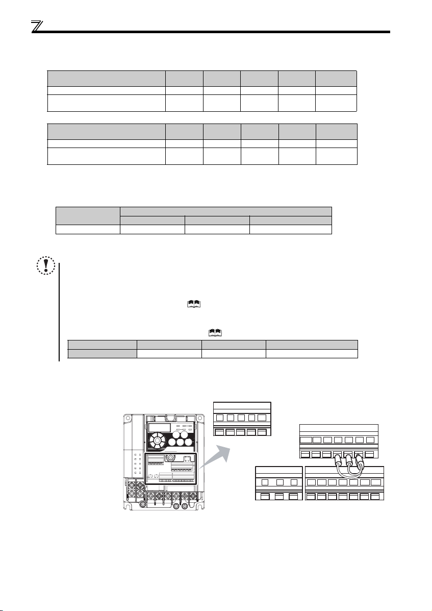
(2) Total wiring length
The overall wiring length for connection of a single motor or multiple motors should be within the value in the table below.
100V, 200V class
Pr. 72 PWM frequency selection Setting
(carrier frequency)
1 (1kHz) or less 200m 200m 300 m 500m 500m
2 to15
(2kHz to 14.5kHz)
0.1K 0.2K 0.4K 0.75K
30m 100m 200m 300m 500m
400V class
Pr. 72 PWM frequency selection Setting
(carrier frequency)
1 (1kHz) or less 200m 200m 300m 50 0m 500m
2 to15
(2kHz to 14.5kHz)
0.4K 0.75K 1.5K 2.2K
30m 100 m 200m 300m 500m
When driving a 400V class motor by the inverter, surge voltages attributable to the wiring constants may occur at the motor
terminals, deteriorating the insulation of the motor. Take the following measures 1) or 2) in this case.
1) Use a «400V class inverter-driven insulation-enhanced motor» and set frequency in Pr. 72 PWM frequency selection
according to wiring length
Wiring Length
50m or less 50m to 100m Exceeding 100m
Carrier frequency
14.5kHz or less 8kHz or less 2kHz or less
2) Connec t the surge voltage suppression filter (FR-A SF-H/FR-BMF -H) on the inverter output side.
NOTE
y Especially for long-distance wiring, the inverter may be affected by a charging current caused by the stray
capacitances of the wiring, leading to a malfunction of the overcurrent protective function, fast response current limit
function, or stall prevention function or a malfunction or fault of the equipment connected on the inverter output side.
If malfunction of fast-response current limit function occurs, disable this function. If malfunction of stall prevention
function occurs, increa se the stall level. ( Refer to Pr. 22 Stall prevention operation level and Pr. 156 Stall prevention
operation selection in the chapter 4 of the Instruction Manual (applied))
y When using the automatic restart after instantaneous power failure function with wiring length exceeding below,
select without frequen cy search (Pr. 162 = «1, 11»). (
Motor capacity 0.1kW 0.2kW 0.4kW or higher
Wiring length 20m 50m 100m
Refer to Chapter 4 of the Instruction M anual (Applied))
1.5K or
higher
3.7K or
higher
2.3.4 Wiring of control circuit
(1) Control circuit terminal layout
Recommend wire size:
0.3mm
2
to 0.75mm
2
13
10 2 5 4
FM
RUN SE S1 S2 SCSO
CBA
SD
STF
PCSDRHRMRL
STR
Loading…
Mitsubishi Electric FR-D720S SC EC DC Drives PDF User Guides and Manuals for Free Download: Found (1) Manuals for Mitsubishi Electric FR-D720S SC EC Device Model (Instruction Manual)
Mitsubishi Electric FR-D720S SC EC Instruction Manual
Details:
- Manufacturer: Mitsubishi Electric
- Product Name/ID: Mitsubishi Electric FR-D720S SC EC / #826390
- Category: DC Drives
- File Path: mitsubishi-electric/fr-d720s-sc-ec_826390.pdf
- Last Updated: 08 May 2025
- Description: The Mitsubishi Electric FR-D720S SC EC manual is your comprehensive guide, providing step-by-step setup instructions, feature exploration tips, and troubleshooting methods to ensure seamless use of your device.
- Document Type: User Manual
- Pages: 512
Download PDF
Read Online
The Mitsubishi Electric FR-D720S SC EC is a versatile variable frequency drive (VFD) that caters to various industrial applications. Known for its reliability and performance, this product has become a go-to choice for many professionals in the field. With advancements in technology and a focus on user experience, Mitsubishi Electric has designed the FR-D720S SC EC to meet the demands of modern industrial environments.
One of the standout features of the FR-D720S SC EC is its user-friendly interface. The drive is equipped with an intuitive keypad that makes programming and monitoring straightforward, even for users with limited experience. The LCD display provides clear feedback, allowing operators to easily navigate through settings and operational data. This feature significantly reduces the learning curve associated with similar products, making it more accessible to a broader audience.
Performance-wise, the Mitsubishi Electric FR-D720S SC EC does not disappoint. It supports a wide range of motor types, including standard AC induction motors and synchronous motors, enabling flexibility across various applications. The drive’s vector control capabilities ensure smooth operation, enhancing efficiency and reducing energy consumption. Furthermore, the FR-D720S SC EC is designed to handle demanding loads without sacrificing performance, making it suitable for heavy-duty industrial use.
Key applications of the FR-D720S SC EC include:
- Pumps and Fans: Optimal speed control for increased efficiency.
- Conveyor Systems: Smooth acceleration and deceleration to prevent material spillage.
- HVAC Systems: Precise control of flow and temperature setups.
- Textile Machines: Consistent speed regulation for enhanced fabric quality.
The Mitsubishi Electric FR-D720S SC EC is also equipped with numerous protective features. Over-voltage and under-voltage protection, thermal overload protection, and short-circuit prevention are just a few of the safety measures that ensure both the drive and connected machinery are safeguarded. These features contribute to minimizing downtime, enhancing the overall reliability of the machine.
Moreover, the energy-saving capabilities of the FR-D720S SC EC are commendable. By adjusting the motor speed according to the load requirements, it optimizes energy consumption, leading to significant cost savings over time. The integration of energy-efficient technologies aligns with Mitsubishi Electric’s commitment to sustainability and environmental responsibility, making the FR-D720S SC EC an excellent choice for green initiatives in manufacturing.
In conclusion, the Mitsubishi Electric FR-D720S SC EC is an exceptional variable frequency drive that offers a blend of performance, efficiency, and user-friendly features. Its adaptability to various applications, coupled with robust safety features, ensures that it stands out among its competitors in the market. Whether you’re looking to enhance productivity, reduce energy consumption, or simply streamline operational processes, the FR-D720S SC EC is a reliable option that won’t let you down.