
Table of Contents
- Fibaro
- FIBARO Heat Controller Thermostat Head
- SKU: FIBEFGT-001
- Quickstart
- Important safety information
- What is Z-Wave?
- Product Description
- Prepare for Installation / Reset
- Reset to factory default
- Safety Warning for Batteries
- Installation
- First launch
- Inclusion/Exclusion
- Inclusion
- Exclusion
- Product Usage
- Controlling the temperature
- Menu
- ” Local protection
- Standby mode
- Battery and charging
- Normal Schedules
- Override Schedule
- Quick trouble shooting
- Association – one device controls an other device
- Association Groups:
- Configuration Parameters
- Parameter 1: Override Schedule duration
- Parameter 2: Additional functions
- Parameter 3: Additional functions status (read-only)
- Technical Data
- Supported Command Classes
- Controlled Command Classes
- Explanation of Z-Wave specific terms
- Read User Manual Online (PDF format)
- Download This Manual (PDF format)
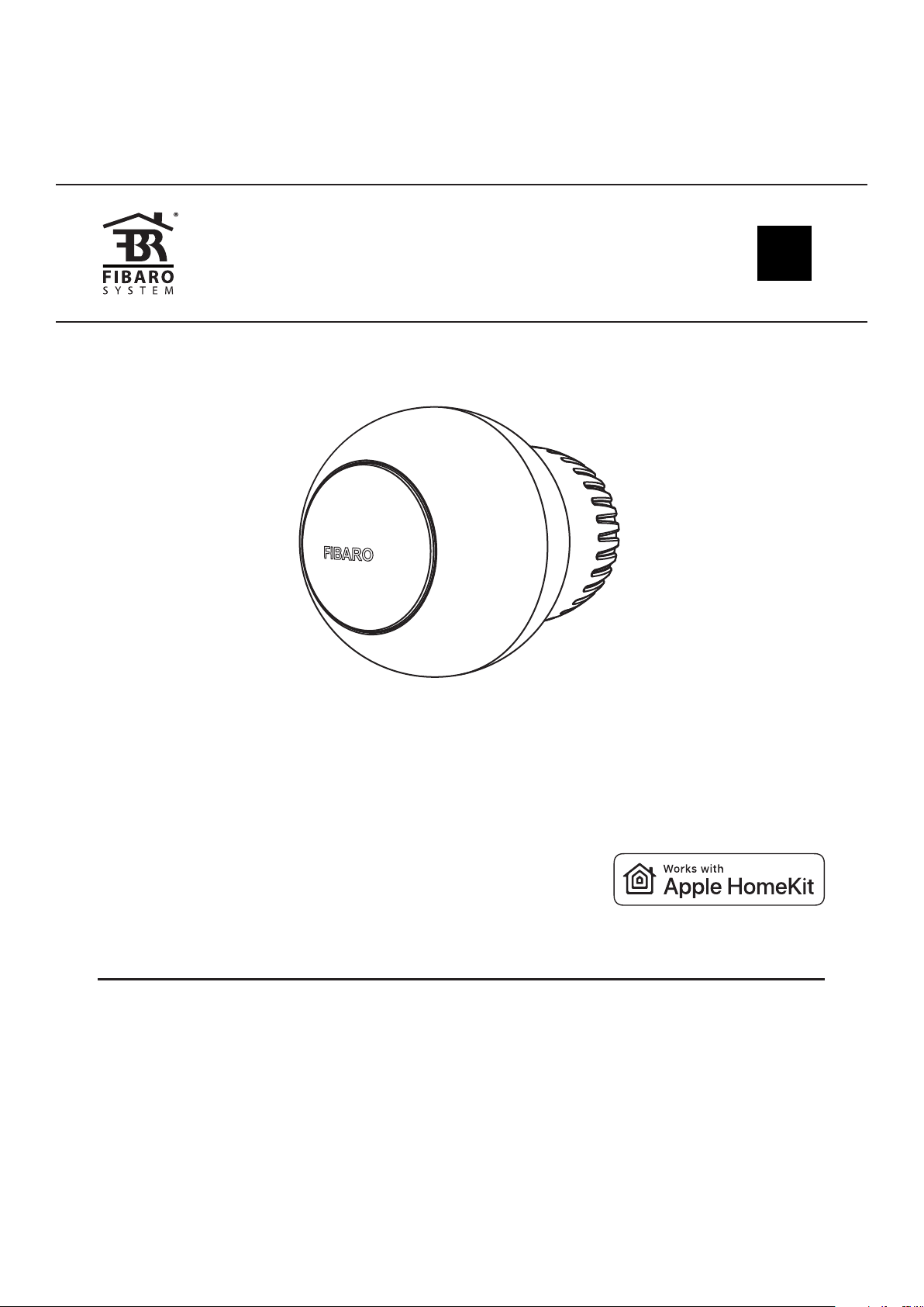
Fibaro
FIBARO Heat Controller Thermostat Head
SKU: FIBEFGT-001
Quickstart
This is a
secure
Z-Wave Device
for
Europe.
To run this device please insert fresh *1 3,7V Li-Poly battery pack**
batteries.
Please make sure the internal battery is fully charged.
To add this device to your network execute the following action:
- Use the included key to quickly triple click the button on the thermostatic head.
Important safety information
Please read this manual carefully. Failure to follow the recommendations in
this manual may be dangerous or may violate the law.
The manufacturer, importer, distributor and seller shall not be liable for any
loss or damage resulting from failure to comply with the instructions in this
manual or any other material.
Use this equipment only for its intended purpose. Follow the disposal
instructions.
Do not dispose of electronic equipment or batteries in a fire or near open
heat sources.
What is Z-Wave?
Z-Wave is the international wireless protocol for communication in the Smart
Home. This
device is suited for use in the region mentioned in the Quickstart section.
Z-Wave ensures a reliable communication by reconfirming every message ( two-
way
communication) and every mains powered node can act as a repeater for other
nodes
( meshed network ) in case the receiver is not in direct wireless range of
the
transmitter.
This device and every other certified Z-Wave device can be used together
with any other
certified Z-Wave device regardless of brand and origin as long as both are
suited for the
same frequency range.
If a device supports secure communication it will communicate with other
devices
secure as long as this device provides the same or a higher level of security.
Otherwise it will automatically turn into a lower level of security to
maintain
backward compatibility.
For more information about Z-Wave technology, devices, white papers etc.
please refer
to www.z-wave.info.
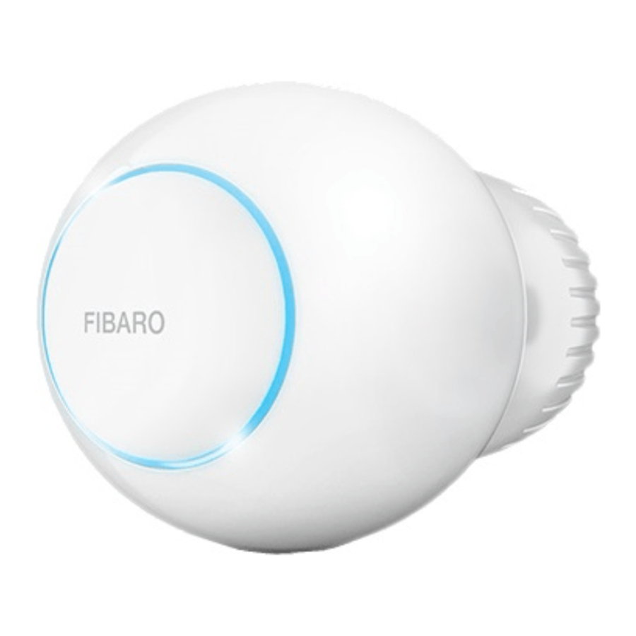
Product Description
FIBARO Radiator Thermostat (Z-Wave) is a remotely controlled thermostatic head
to control temperature in your room. It measures the temperature and
automatically adjusts the heat level. It can be mounted without tools on three
types of thermostatic radiator valves. You can create schedules via app to
easily manage temperature throughout the week.
Prepare for Installation / Reset
Please read the user manual before installing the product.
In order to include (add) a Z-Wave device to a network it must be in factory
default
state. Please make sure to reset the device into factory default. You can do
this by
performing an Exclusion operation as described below in the manual. Every
Z-Wave
controller is able to perform this operation however it is recommended to use
the primary
controller of the previous network to make sure the very device is excluded
properly
from this network.
Reset to factory default
This device also allows to be reset without any involvement of a Z-Wave
controller. This
procedure should only be used when the primary controller is inoperable.
– Use the included key to press and hold the button
– Release the button when you see yellow LED colour.
– Click the button to confirm the selection.
– After finishing resetting the device will be put in Standby Mode. Click the
button to activate it again.
Safety Warning for Batteries
The product contains batteries. Please remove the batteries when the device is
not used.
Do not mix batteries of different charging level or different brands.
Installation
First launch
-
1. 1\. Connect the charger to the micro-USB port to charge the device.
If you have the temperature sensor:
“
-
1. * Use a coin to open the battery cover by turning it counter-clockwise.- Remove the sticker underneath the battery.
- Use a coin to close the battery cover by turning it clockwise.
- 2. Disconnect the charger when the LED ring pulses green (device fully charged).
First charging may take up to 3 hours.
- 3. Dismount your current thermostatic head.
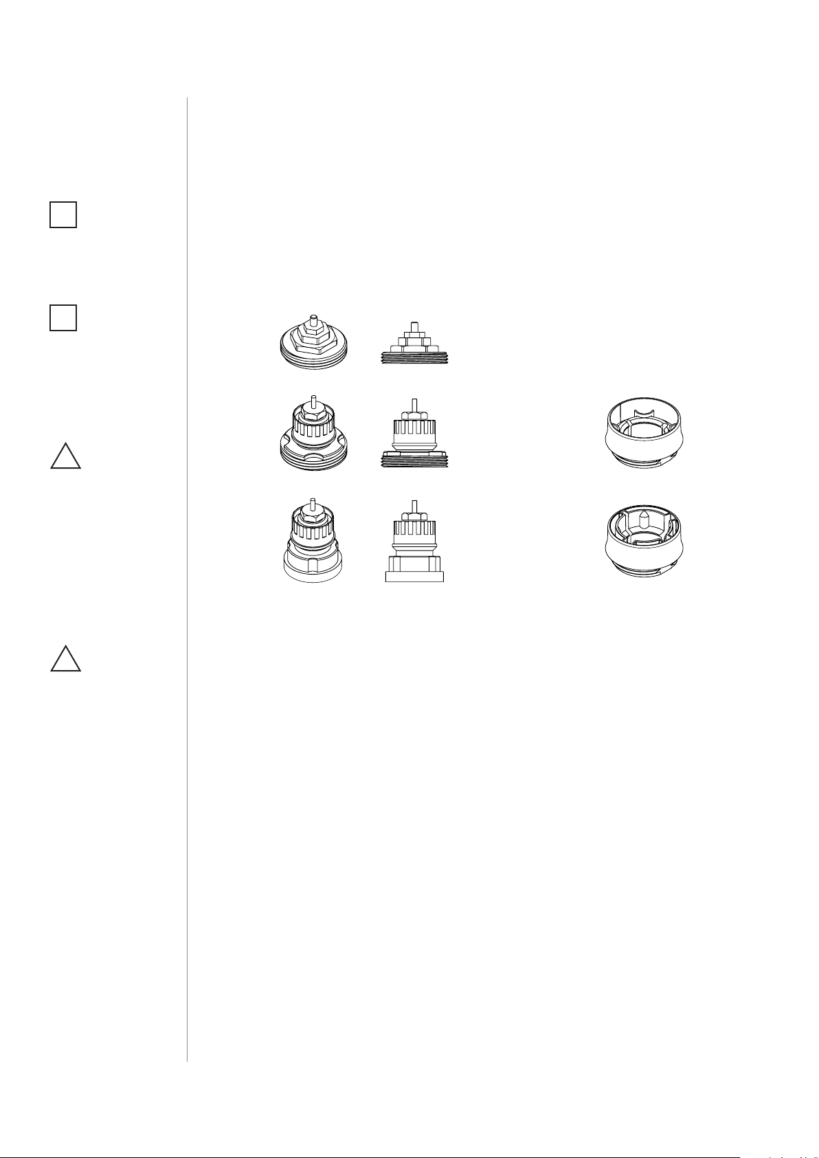
- 4. Depending on type of your thermostatic valve:
If you use one of the adapters, double check that it is mounted properly. It
should click when putting on the valve, hold tight after installing and not
rotate!
“
Install the device in horizontal position only!
5. Mount the device on the valve and tighten it by turning the cap clockwise.
6. Use the included key to click the button.
7. The LED ring will start blinking blue.
If you have the temperature sensor:
“
-
* Click the button on it now.
-
* The LED ring will blink green 5 times if the connection was successful.
Do not cover or veil the thermostatic head.
Inclusion/Exclusion
On factory default the device does not belong to any Z-Wave network. The
device needs
to be added to an existing wireless network to communicate with the
devices of this network.
This process is called Inclusion.
Devices can also be removed from a network. This process is called
Exclusion.
Both processes are initiated by the primary controller of the Z-Wave network.
This
controller is turned into exclusion respective inclusion mode. Inclusion and
Exclusion is
then performed doing a special manual action right on the device.
Inclusion
- Use the included key to quickly triple click the button on the thermostatic head.
Exclusion
- Use the included key to quickly triple click the button on the thermostatic head.
Product Usage
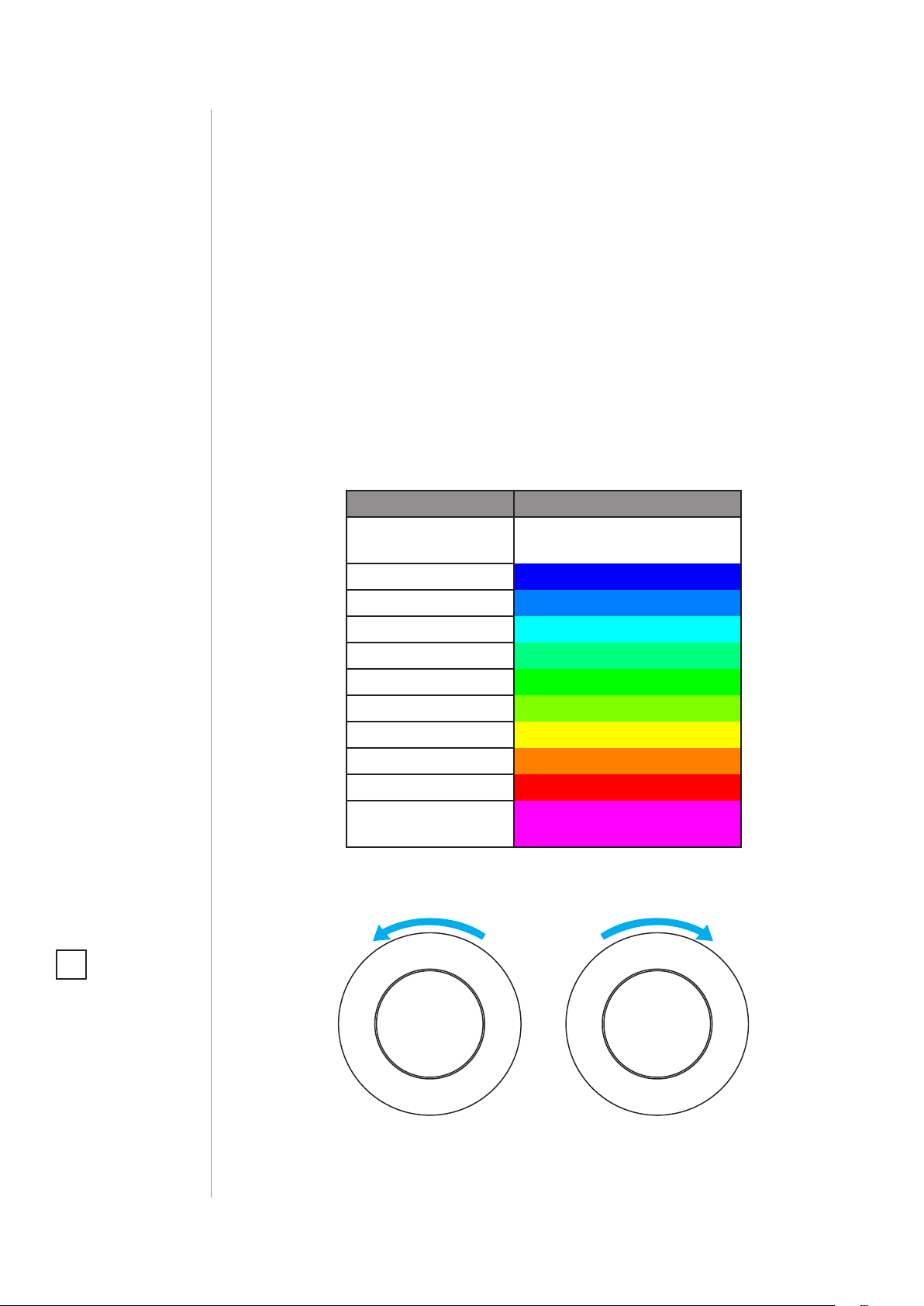
Controlling the temperature
You can set temperature using app (10-30″°C) or directly on the device
(16-24″°C).
During manual temperature change LED ring colour corresponds to the
temperature set-point.
To check and change the temperature on the device:
1. Bring your hand close to the sphere.
2. LED ring will:
-
1. * Glow if temperature was set manually,- Pulse slowly if device is in schedule mode,
- Pulse quickly if device is in override schedule mode.
With colour depending on set temperature:
| Z-Wave Mode | Temperature [“°C] | Colour |
|---|---|---|
| OFF | Valve closed (anti-freeze) | White |
| HEAT | 16″°C or lower | Blue |
| 17″°C | Azure | |
| 18″°C | Cyan | |
| 19″°C | Spring green | |
| 20″°C | Green | |
| 21″°C | Chartreuse | |
| 22″°C | Yellow | |
| 23″°C | Orange | |
| 24″°C or higher | Red | |
| MANUFACTURER SPECIFIC | Valve fully opened | Magenta |
3. Turn the sphere counter-clockwise to lower temperature or turn clockwise
to raise the temperature
4.” Remove the hand from the sphere, after 5 seconds LED will fade and new
temperature will be set.
If device is currently during normal schedule, setting temperature manually
will set Override Schedule.
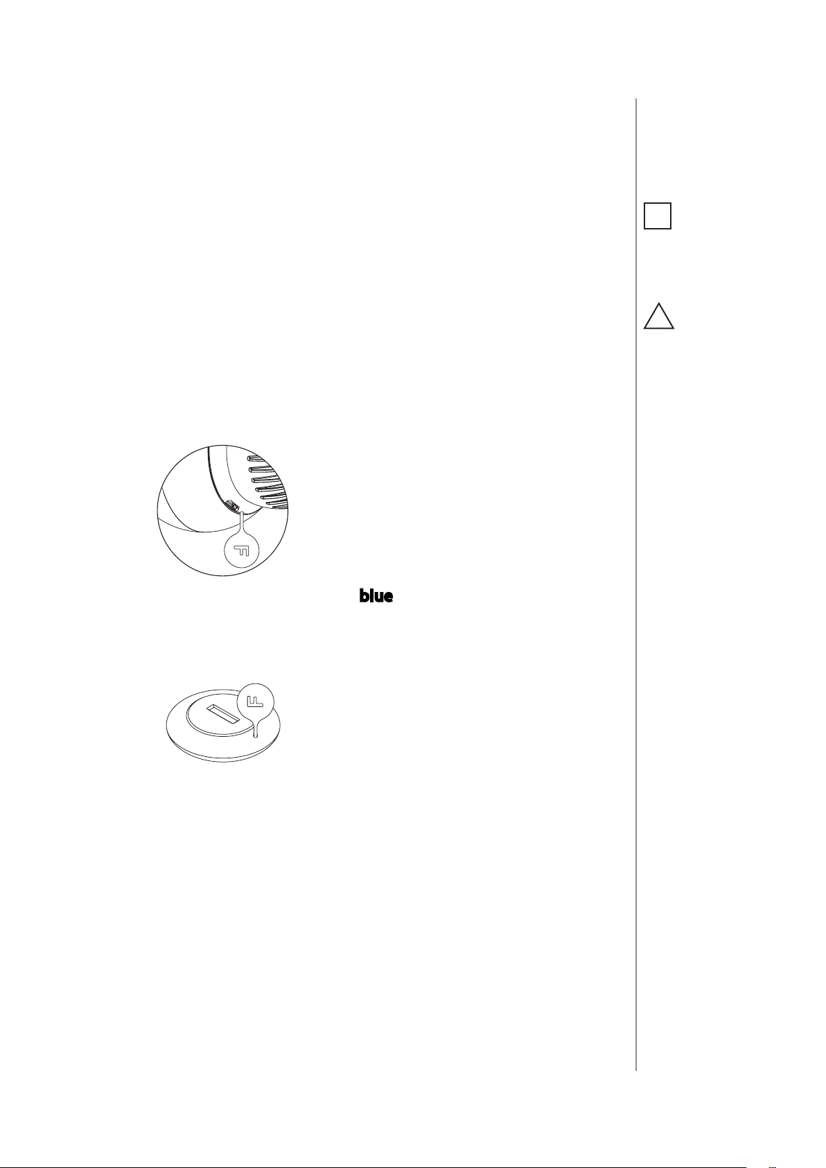
Menu ” allows to perform important configuration and maintenance actions.
In order to use the menu:
1.Use the included key to press and hold the button.
2. Release the button when you see desired LED colour
Colour
Blue| pair dedicated temperature sensor
Red| enable/disable local control protection
White| perform head calibration
Green| adding/removing to/from Z-Wave network
Magenta| Z-Wave network’s range test
Cyan| put device in Standby Mode
Yellow| factory reset
3. Click the button to confirm the selection.
” Local protection
“
After enabling the local protection changing temperature directly on the
device (by turning it) will not be possible.
Enabling local protection is recommended if you want to prevent accidental
temperature change, e.g. by children.
When attempting to change temperature if local protection is enabled:
- The device will not set new target temperature,
- The LED ring will blink red 3 times.
To change the temperature use the app or disable the local protection.
Local protection can also be enabled/disabled using Z-Wave protocol Command
Class Protection
Standby mode
In” Standby Mode ” the device is in deep sleep state allowing safe
dismounting, transporting and low as possible battery consumption.
The device is shipped in Standby Mode.
Entering the device in Standby Mode will not factory reset the device nor will
result in loosing any data.
To ” exit Standby Mode ” click the button once, the device will enter
first installation procedure.
Battery and charging
The device is equipped with a rechargeable lithium-polymer battery pack that
can be charged via micro-USB port using standard 5V charger (not included).
When battery is low the LED ring will start to blink red. The device will also
report low battery status of itself and dedicated temperature sensor (if
paired) to the controller.
Make sure you are using certified charger Class II, which complies with
parameters specified in the manual.
Do not leave the device unattended while charging.
Do not use cables longer than 3 meters for charging the device.
“
To charge the battery:
1. Connect charger to the micro-USB port.
2. During charging the LED ring will pulse red and valve control will be
disabled.
3. When LED starts pulsing green, disconnect the charger.
4. The device will restore its previous operation.
Normal Schedules
“
The device allows to create multiple” heating schedules ” to manage
temperature in the room throughout the week. Schedules are created via
controller interface or app.
- Up to 253 normal schedules can be created,
- The lower the schedule ID number, the higher the priority,
- Schedules with higher priority override those with lower priority in case of overlapping schedules,
- Schedules can be disabled without deleting it,
- Schedules allow to set target temperature, fully open the valve or fully close the valve.
To create normal schedules user must specify:
- Day of the week,
- Starting time (hour and minute),
- Duration,
- Temperature setpoint in range 10-30″°C (for HEAT mode),
- One of the operating modes:
- HEAT for setting temperature,
- OFF for valve fully closed,
- MANUFACTURER SPECIFIC for valve fully opened.
Override Schedule
Override Schedule ” is a special type schedule that has the highest
priority; thus it overrides other schedules.
The Override Schedule starts right after setting and lasts for specified time,
then it is removed and current schedule or normal operation is restored.
To create Override Schedule user must specify:
- Duration,
- Temperature setpoint in range 10-30″°C (for HEAT mode),
- One of the operating modes:
- HEAT for setting temperature,
- OFF for valve fully closed,
- MANUFACTURER SPECIFIC for valve fully opened.
Override Mode can be” enabled ” in two ways:
- By turning the knob, while normal schedule is active. The LED ring will pulse with selected adjustment.
- Via controller, by creating schedule with ID set 255, start time set to NOW and duration (in minutes/hours/days).
To” exit ” Override Mode grab knob with your hand for 5 seconds.
“
Quick trouble shooting
Here are a few hints for network installation if things dont work as expected.
- Make sure a device is in factory reset state before including. In doubt exclude before include.
- If inclusion still fails, check if both devices use the same frequency.
- Remove all dead devices from associations. Otherwise you will see severe delays.
- Never use sleeping battery devices without a central controller.
- Dont poll FLIRS devices.
- Make sure to have enough mains powered device to benefit from the meshing
Association – one device controls an other device
Z-Wave devices control other Z-Wave devices. The relationship between one
device
controlling another device is called association. In order to control a
different
device, the controlling device needs to maintain a list of devices that will
receive
controlling commands. These lists are called association groups and they are
always
related to certain events (e.g. button pressed, sensor triggers, …). In case
the event happens all devices stored in the respective association group will
receive the same wireless command wireless command, typically a ‘Basic Set’
Command.
Association Groups:
Group NumberMaximum NodesDescription
| 1 | 1 | Lifeline |
|---|
Configuration Parameters
Z-Wave products are supposed to work out of the box after inclusion, however
certain configuration can adapt the function better to user needs or unlock
further
enhanced features.
IMPORTANT: Controllers may only allow configuring
signed values. In order to set values in the range 128 … 255 the value sent in
the application shall be the desired value minus 256. For example: To set a
parameter to 200 it may be needed to set a value of 200 minus 256 = minus
56.
In case of a two byte value the same logic applies: Values greater than 32768
may
needed to be given as negative values too.
Parameter 1: Override Schedule duration
__
Size: 4 Byte, Default Value: 240
SettingDescription
| 10 – 10000 | Time in minutes |
|---|
Parameter 2: Additional functions
This parameter allows to enable different additional functions of the
device.
Parameter 2 values may be combined, e.g. 1+8=9 means that Open Window Detector
and LED indications when controlling remotely are enabled.
Size: 4 Byte, Default Value: 1
SettingDescription
| 1 | enable Open Window Detector |
|---|---|
| 2 | enable fast Open Window Detector |
| 4 | increase receiver sensitivity (shortens battery life) |
| 8 | enabled LED indications when controlling remotely |
| 16 | protect from setting Full ON and Full OFF mode by turning the knob |
manually
Parameter 3: Additional functions status (read-only)
This parameter allows to check statuses of different additional functions.
Size: 4 Byte, Default Value: 0
SettingDescription
| 1 | optional temperature sensor connected and operational |
|---|---|
| 2 | open window detected |
Technical Data
| Dimensions | 56x56x74 mm |
|---|---|
| Weight | 113 gr |
| Hardware Platform | ZM5202 |
| EAN | 5902701701062 |
| IP Class | IP 20 |
| Battery Type | 1 * 3,7V Li-Poly battery pack |
| Firmware Version | 04.00 |
| Z-Wave Version | 04.3d |
| Certification ID | ZC10-17125896 |
| Z-Wave Product Id | 0x010f.0x1301.0x1000 |
| Frequency | Europe – 868,4 Mhz |
| Maximum transmission power | 5 mW |
Supported Command Classes
- Basic
- Application Status
- Sensor Multilevel
- Thermostat Mode
- Thermostat Setpoint
- Crc 16 Encap
- Association Grp Info
- Device Reset Locally
- Zwaveplus Info
- Multi Channel
- Supervision
- Configuration
- Alarm
- Manufacturer Specific
- Powerlevel
- Protection
- Firmware Update Md
- Battery
- Clock
- Association
- Version
- Multi Channel Association
- Security
- Security 2
- Schedule
- Transport Service
Controlled Command Classes
- Schedule
- Transport Service
Explanation of Z-Wave specific terms
-
Controller — is a Z-Wave device with capabilities to manage the network.
Controllers are typically Gateways,Remote Controls or battery operated wall
controllers. -
Slave — is a Z-Wave device without capabilities to manage the network.
Slaves can be sensors, actuators and even remote controls. -
Primary Controller — is the central organizer of the network. It must be
a controller. There can be only one primary controller in a Z-Wave network. -
Inclusion — is the process of adding new Z-Wave devices into a network.
-
Exclusion — is the process of removing Z-Wave devices from the network.
-
Association — is a control relationship between a controlling device and
a controlled device. -
Wakeup Notification — is a special wireless message issued by a Z-Wave
device to announces that is able to communicate. -
Node Information Frame — is a special wireless message issued by a
Z-Wave device to announce its capabilities and functions.
Read User Manual Online (PDF format)
Read User Manual Online (PDF format) >>
Download This Manual (PDF format)
Download this manual >>
OPERATING
MANUAL
EN
THE HEAT CONTROLLER
RADIATOR THERMOSTAT
FGBHT-001
CONTENTS
#1: Description and features 3
#2: Basic activation 4
#3: Pairing with HomeKit (FGBHT-001) 5
#4: Controlling the temperature 6
#5: Extra temperature sensor 7
#6: Dismounting the device 8
#7: Menu 9
#8: Local protection 10
#9: Head calibration 11
v1.0
#10: Standby Mode 12
#11: Factory reset 13
#12: Battery and charging 14
#13: Schedules and Override Mode 15
#14: Congurable parameters 16
#15: Status faults 17
#16: Specications 18
#17: Sensor specication (FGBRS-001) 20
#18: Regulations 21

2
Important safety information
Read this manual before attempting to install the device!
!
Failure to observe recommendations included in this manual
may be dangerous or cause a violation of the law. The manufacturer,
Fibar Group S.A. will not be held responsible for any loss or damage
resulting from not following the instructions of operating manual.
This product is not a toy. Keep away from children and animals!
CR2032 coin cell battery is harmful if swallowed!
Battery pack warning!
The Heat Controller contains lithium-ion polymer battery pack, heed
all following warnings:
• If an unusual odor or malfunction is detected, avoid sources of
open ame and remove the device from the radiator.
• In the event of damage from crashes, etc, carefully remove to a
safe place for at least a half hour to observe.
• Do not leave the device unattended while charging.
• Do not attempt to replace the battery!
HomeKit technology
Apple HomeKit technology provides an easy, secure way to control
HomeKit-enabled accessories using Siri on your iPhone, iPad, or iPod
touch.
After installing your FIBARO Heat Controller congure it from a
compatible app with just a few simple steps.
You can even create your own custom scenes to control your home
settings. For example, you can create a scene to automatically turn
o the lights, lock your doors, close the garage door, and set the
thermostat to the desired temperature in just one step.
To control this HomeKit-enabled accessory, iOS 11.2 or later is
i
recommended.
Controlling this HomeKit-enabled accessory automatically and
away from home requires an Apple TV with tvOS 11 or later,
a HomePod or an iPad with iOS 11.2 or later set up as a home
hub.

#1: Description and features
FIBARO Heat Controller is a HomeKit-enabled, remotely controlled
thermostatic head to control temperature in your room using
Bluetooth® low energy wireless technology.
It measures the temperature and automatically adjusts the heat level.
It can be mounted without tools on three types of thermostatic
radiator valves.
You can create schedule via app to easily manage temperature
throughout the week.
Main features of FIBARO Heat Controller:
• to be installed on three types of valves: M30 x 1.5, Danfoss RTD-N
and Danfoss RA-N,
3
• compatible with Apple HomeKit technology,
• Bluetooth® low energy technology for wireless communication,
• built-in battery recharged through standard micro-USB port,
• easy installation — no tools required,
• can use an external temperature sensor — FGBRS-001,
• supports weekly heating schedule,
• automatic calibration,
• anti-freeze function,
• decalc function,
• unconstrained rotation spherical knob to set desired temperature.
3 types of controlling the temperature in FIBARO Heat Controller:
• manually — directly on the device,
• schedule mode — creating scheduling rules to manage temperature
in the room throughout the week. Schedule is created via app,
• override mode — replaces currently scheduled temperature for a
specic time.
DESCRIPTION AND FEATURES
4
#2: Basic activation
NOTE
i
First charging may take
up to 3 hours.
NOTE
i
In order to achieve
the best performance
install the device in
horizontal position.
CAUTION
!
If you use one of the
adapters, double check
that it is mounted
properly. It should
click when putting on
the valve, hold tight
after installing and
not rotate!
1. Connect the charger to the micro-USB port to charge the device.
2. Disconnect the charger when the LED ring pulses green (device
fully charged).
3. Dismount your current thermostatic head.
4. Depending on type of your thermostatic valve:
Proceed normally
M30 x 1.5
Use adapter:
Danfoss RTD-N
Use adapter:
Danfoss RA-N
5. Mount the device on the valve and tighten it by turning the cap
clockwise.
CAUTION
!
Do not cover or veil the
thermostatic head.
BASIC ACTIVATION
#3: Pairing with HomeKit
(FGBHT-001)
1. Open the Settings app on your iOS device.
2. Go to the Bluetooth® section, and turn the Bluetooth® on.
3. Place the accessory next to your iOS device.
4. Open a HomeKit compatible app of your choosing on your iOS
device.
5. Find HomeKit Setup Code on the last page of Quick Start Guide
included in the box that looks like this:
5678
5
NOTE
i
You will nd the Setup
Code on the device’s
housing and on the
back of the Quick Start
Guide.
6. Start pairing with your HomeKit app.
7. Follow instructions displayed in the application.
PAIRING WITH HOMEKIT FGBHT001
6
#4: Controlling the temperature
You can set temperature using app (10-30°C) or directly on the device
(16-24°C). During manual temperature change LED ring colour corresponds to the temperature set-point.
To check and change the temperature on the device:
1. Bring your hand close to the sphere.
2. LED ring will:
• Glow if temperature was set manually,
• Pulse slowly if device is in schedule mode,
• Pulse quickly if device is in override mode.
With colour depending on set temperature:
Temperature [°C] Colour
Valve closed
(anti-freeze)
16°C or lower Blue
17°C Azure
18°C Cyan
19°C Spring green
20°C Green
21°C Chartreuse
22°C Yellow
23°C Orange
24°C or higher Red
Valve fully opened
(30°C)
White
Magenta
3. Turn the sphere counter-clockwise to lower temperature or turn
clockwise to raise the temperature.
NOTE
i
If device is currently
in schedule, setting
temperature manually will override it (see
“Weekly schedule and
Override Mode” on
page 15).
4. Remove the hand from the sphere, after 5 seconds LED will fade
and new temperature will be set.
CONTROLLING THE TEMPERATURE
Lower temperature Raise temperature
#5: Extra temperature sensor
7
The device can be used with an additional, dedicated temperature
sensor (FGBRS-001) to provide the best temperature regulation.
It can be placed anywhere in the room and the device will use it as a
reference point for the room temperature.
Before using, the sensor must be paired with the thermostatic head.
One thermostatic head can be paired with only one sensor, but one
sensor can be paired with up to three thermostatic heads.
To pair the FGBRS-001 with the device:
1. Use the included key to press and hold the button.
2. Release the button when you see blue LED colour.
NOTE
i
FGBRS-001 is the only
compatible external
temperature sensor.
CAUTION
!
This product is not a
toy. Keep away from
children and animals!
3. Quickly click the button to conrm, the LED ring will start blinking
blue.
4. Within 1 minute click button on the sensor.
5. The LED ring on thermostatic head will glow green to conrm successful pairing.
6. Place the sensor in same room as head, no further than 5 meters
from it.
To remove all paired heads:
1. Press and hold the button on the sensor for 2 seconds.
2. LED on the sensor will blink 3 times to conrm unpairing.
EXTRA TEMPERATURE SENSOR
Loading…
FIBARO FGT-001 — Heat Controller Manual
Description and features
FIBARO Heat Controller is a remotely controlled thermostatic head to control temperature in your room. It measures the temperature and automatically adjust the heat level.
It can be mounted without tools on three types of thermostatic radiator valves.
You can create schedules via app to easily manage temperature throughout the week.
Main features of FIBARO Heat Controller:
- to be installed on three types of valves: M30 x 1.5, Danfoss RTD-N and Danfoss RA-N,
- compatible with any certified Z-Wave and Z-Wave Plus Controller,
- supports Z-Wave network Security Modes: S0 with AES-128 encryption and S2 with PRNG-based encryption,
- built-in battery recharged through standard micro-uSB port,
- easy installation — no tools required,
- can use a dedicated temperature sensor — FGBRS-001,
- supports heating schedules,
- automatic calibration,
- anti-freeze function,
- descaling function,
- unconstrained rotation spherical knob to set desired temperature.
FIBARO Heat Controller is a fully compatible Z-Wave Plus device.
NOTE
This device may be used with all devices certified with Z-Wave Plus certificate and should be compatible with such devices produced by other manufacturers.
NOTE
Z-Wave Controller must support Z-Wave Security Mode in order to fully utilize the product.
NOTE
First charging may take up to 3 hours.
If you use one of the adapters, double check that it is mounted properly. It should click when putting on the valve, hold tight after installing and not rotate!
If the device is installed in vertical position, set bit 5 in parameter 2.
Do not cover or veil the thermostatic head.
Basic activation
- Connect the charger to the micro-uSB port to charge the device. The LED ring will pulse red if it’s not fully charged; otherwise, it will pulse green.
If you have the temperature sensor:- use a coin to open the battery cover by turning it counter-clockwise.
- Remove the sticker underneath the battery.
- use a coin to close the battery cover by turning it clockwise.
- Disconnect the charger when the LED ring pulses green (device fully charged).
- Dismount your current thermostatic head.

- Depending on type of your thermostatic valve:
- Mount the device on the valve and tighten it by turning the cap clockwise.
- Press and hold the button for at least one second (A) or use the included key to quickly triple click the button (B).
- The LED ring will start blinking blue.
If you have the temperature sensor:- Click the button on the temperature sensor now.
- The LED ring on the thermostatic valve will blink green 5 times if the connection was successful.

If you use one of the adapters, double check that it is mounted properly. It click when putting on the valve, hold tight after installing and not rotate!
If the device is installed in vertical position, set bit 5 in parameter 2.
Do not cover or veil the thermostatic head.
Adding to Z-Wave network
Adding (Inclusion) — Z-Wave device learning mode, allowing to add the device to existing Z-Wave network.
To add the device to the Z-Wave network:
- Make sure the device is within the direct range of your Z-Wave controller.
- Set the main controller in (security/non-security) add mode (see the controller’s manual)
- Quickly triple click the button on the thermostatic head (A) or use the included key (B).
- The LED ring will start blinking white.
- If you are adding in S2 authenticated mode, type in the device pin code (underlined part of the public key on the label).
- Wait for the adding process to end.
- Successful adding will be confirmed by the Z-Wave controller and green LED colour.
Removing the device
Removing (Exclusion) — Z-Wave device learning mode, allowing to remove the device from existing Z-Wave network.
To remove the device from the Z-Wave network:
- Make sure the device is within the direct range of your Z-Wave controller.
- Set the main controller into remove mode (see the controller’s manual).
- Quickly triple click the button on the thermostatic head (A) or use the included key (B).
- The LED ring will start blinking white.
- Wait for the removing process to end.
- Successful removing will be confirmed by the Z-Wave controller and red LED colour.
NOTE
Removing the device from the Z-Wave network restores all the default parameters of the device.
Controlling the temperature
You can set temperature using app (10-30°C) or directly on the device (16-24°C).
During manual temperature change LED ring colour corresponds to the temperature set-point.
To check and change the temperature on the device:
- Bring your hand close to the sphere.
- LED ring will:
- Glow if temperature was set manually,
- Pulse slowly if device is in schedule mode,
- Pulse quickly if device is in override schedule mode.
With colour depending on set temperature:

- Turn the sphere counter-clockwise to lower temperature or turn clockwise to raise the temperature.
- Remove the hand from the sphere, after 5 seconds LED will fade and new temperature will be set.

NOTE
If device is currently during normal schedule, setting temperature manually will set Override Schedule (see «Override Schedule»)
The device can be used with an additional, dedicated temperature sensor (FGBRS-001) to provide the best temperature regulation.
It should be placed in the same room or heating zone as the thermostatic head which will use it as a reference point for the room temperature.
Before using, the sensor must be paired with the thermostatic head. One thermostatic head can be paired with only one sensor, but one sensor can be paired with up to three thermostatic heads.
To pair the FGBRS-001 with the device:
- Press and hold the button on the thermostatic head (A) or use the included key (B).
Release the button when you see blue LED colour
- Click the button to confirm the selection, the LED ring will start blinking blue.
- Within 1 minute click the button on the sensor.
- The LED ring on thermostatic head will glow green to confirm successful pairing.
- Place the sensor in same room as head, no further than 5 meters from it.
To remove all paired heads from the sensor’s memory:
- Press and hold the button on the sensor for 2 seconds.
- The LED on the sensor will blink 3 times to confirm unpairing.
NOTE
FGBRS-001 is the only compatible temperature sensor.
This product is not a toy. keep away from children and animals!
Dismounting the device
Before dismounting, the device must be put in Standby Mode to ensure safe removal. See chapter „Standby Mode» for more information.
To dismount the device:
- Press and hold the button (A) or use the included key (B).
Release the button when you see cyan LED colour.
- Click the button to confirm the selection.
- Turn the cap counter-clockwise and remove adapter if used.
- Store the device in temperature: -10°C to 25°C.
Menu allows to perform important configuration and maintenance actions. In order to use the menu:
- Press and hold the button (A) or use the included key (B).
- Release the button when you see desired LED colour:
- Click the button to confirm the selection.

Local protection
After enabling the local protection changing temperature directly on the device (by turning it) will not be possible.
Enabling local protection is recommended if you want to prevent accidental temperature change, e.g. by children.
When attempting to change temperature if local protection is enabled:
- The device will not set new target temperature,
- The LED ring will blink red 3 times.
To change the temperature use the app or disable the local protection.
To enable/disable local protection using the menu: NOTE
- Press and hold the button (A) or use the included key (B).Local protection can also be enabled/ disabled remotely through Z-Wave controller.
Release the button when you see red LED colour.
- Click the button to confirm the selection.
NOTE
Local protection can also be enabled/ disabled remotely through Z-Wave controller.
Head calibration
Calibrating the device to your radiator valve is required for proper controlling the temperature.
Calibration is performed:
- Automatically, after 10 minutes from turning on if no operation on the device has been made (only at first installation),
- Automatically, after 10 minutes from last state change (only at first installation),
- Manually, using the menu (see below).
To perform calibration using the menu:
- Press and hold the button (A) or use the included key (B).
Release the button when you see white LED colour.
- Click the button to confirm the selection.
NOTE
Calibration cannot be performed while the device is being charged.
Standby Mode
In Standby Mode the device is in deep sleep state allowing safe dismounting, transporting and low as possible battery consumption.
The device is shipped in Standby Mode. It should be fully charged before first use.
Entering the device in Standby Mode will not factory reset the device nor will result in loosing any data, but calibration and sensor pairing (after long Standby) is lost.
We recommend unpairing temperature sensor before putting the device into Standby Mode.
To enter Standby Mode:
- Press and hold the button (A) or use the included key (B).
Release the button when you see cyan LED colour.
- Click the button to confirm the selection.
To exit Standby Mode click the button once, the device will enter first installation procedure.
Factory reset
Reset procedure allows to restore the device back to its factory settings, which means all information about the network and user configuration will be deleted.
To perform factory reset:
- Press and hold the button (A) or use the included key (B).
Release the button when you see yellow LED colour.
- Click the button to confirm the selection.
- After finishing resetting the device will be put in Standby Mode.
Click the button to activate it again.
NOTE
Resetting the device is not the recommended way of removing the device from the Z-Wave network. use the reset procedure only if the primary controller is missing or inoperable.
Z-Wave range test
The device has a built in Z-Wave network main controller’s range tester.
To perform range test:
- Press and hold the button (A) or use the included key (B).
Release the button when you see magenta LED colour.
- Click the button to confirm the selection.
- LED ring will indicate the Z-Wave network’s range:
Pulsing green — the device attempts to establish a direct communication with the main controller. If a direct communication attempt fails, the device will try to establish a routed communication, through other modules, which will be signaled by visual indicator pulsing yellow.
Glowing green — the device communicates with the main controller directly.
Pulsing yellow — the device tries to establish a routed communication with the main controller through other modules (repeaters).
Glowing yellow — the device communicates with the main controller through the other modules. After 2 seconds the device will retry to establish a direct communication with the main controller, which will be signaled with visual indicator pulsing green.
Pulsing magenta — the device does communicate at the maximum distance of the Z-Wave network. If connection proves successful it will be confirmed with a yellow glow. It’s not recommended to use the device at the range limit.
Glowing red — the device is not able to connect to the main controller directly or through another Z-Wave network device (repeater). - To exit Z-Wave range test, press the button briefly.
Battery and charging
The device is equipped with a rechargeable lithium-polymer battery pack that can be charged via micro-uSB port using standard 5v charger (not included).
When battery is low the LED ring will start to blink red. The device will also report low battery status of itself and dedicated temperature sensor (if paired) to the controller.
The device does not operate the valve during the charging and maintains the last valve position.
If the battery is discharged the device will open valve completely to allow easy dismounting.
To charge the battery:
- Connect charger to the micro-uSB port.
- During charging the LED ring will pulse red and valve control will be disabled.
- When LED starts pulsing green, disconnect the charger.
- The device will restore its previous operation.
Make sure you are using certified charger Class II, marked which complies with parameters specified in the manual.
Do not leave the de vice unattended while charging.
Set the device to OFF (white) before charging or dismount the thermostatic head if not possible. i NOTE Do not use cables longer than 3 meters for charging the device.
Make sure the device won’t discharge during the heating season or it may cause high temperatures!
A charging error is signalled by a flashing magenta colour.
Normal Schedules
The device allows to create multiple heating schedules to manage temperature in the room throughout the week. Schedules are created via controller interface or app.
- Up to 253 normal schedules can be created.
- The lower the schedule ID number, the higher the priority.
- Schedules with higher priority override those with lower priority in case of overlapping schedules.
- Schedules can be disabled without deleting it.
- Schedules allow to set target temperature for HEAT mode (using Thermostat Setpoint CC) and one of operating modes: HEAT, OFF or MANUFACTURER SPECIFIC (using Thermostat Mode CC)
- Only SET commands are permitted.
To create normal schedules user must specify:
- Day of the week,
- Starting time (hour and minute),
- Duration,
- Temperature Setpoint for HEAT mode in range 10-30°C (using Thermostat Setpoint CC)
- One of the operating modes (using Thermostat Mode CC):
- HEAT for setting temperature,
- OFF for valve fully closed,
- MANuFACTuRER SPECIFIC for valve fully opened.
NOTE
Schedule CC Set command payload must not be greater than 22 bytes limit or it would be rejected.
Override Schedule
Override Schedule is a special type schedule with highest priority; thus it overrides other schedules.
The Override Schedule starts right after setting and lasts for specified time, then it is removed and current schedule or normal operation is restored.
To create Override Schedule user must specify:
- Starting time (START NOW),
- Duration,
- Temperature Setpoint for HEAT mode in range 10-30°C (using Thermostat Setpoint CC)
- One of the operating modes (using Thermostat Mode CC):
- HEAT for setting temperature,
- OFF for valve fully closed,
- MANUFACTURER SPECIFIC for valve fully opened.
Override Mode can be enabled in two ways:
- By turning the knob, while normal schedule is active. The LED ring will pulse with selected adjustment.
- via controller, by creating schedule with ID set 255, start time set to NOW and duration (in minutes/hours/days).
To exit Override Mode grab knob with your hand for 5 seconds.
Z-Wave specification
Endpoint 1:
Generic Device Class: GENERIC_TYPE_THERMOSTAT
Specific Device Class: SPECIFIC_TYPE_THERMOSTAT_GENERAL_V2
Description: represents thermostatic head, allows to set temperature, schedules and check its battery level.
Endpoint 2:
Generic Device Class: GENERIC_TYPE_SENSOR_MULTILEVEL
Specific Device Class: SPECIFIC_TYPE_ROUTING_SENSOR_MULTILEVEL
Description: represents temperature sensor:
- Extra temperature sensor paired – reports temperature measured by the extra sensor and its battery level,
- No extra temperature sensor paired – reports temperature measured by the built-in sensor and head battery level.
Response to Basic Command Class:
| Value | Action |
| 0 | Set OFF mode (unfreeze function) |
| 99 | Set HEAT mode (last set temperature) |
| 255 | Set MANUFACTURER SPECIFIC mode (valve fully opened) |
Association Command Class:
The device supports only «Lifeline» association group that reports the device status and allows for assigning single device only (main controller by default).
Supported Command Classes:
| Command Class | Version | Secure |
| ZWAVEPLUS_INFO [0x5E] | V2 | |
| ASSOCIATION [0x85] | V2 | YES |
| MULTI_CHANNEL_ASSOCIATION [0x8E] | V3 | YES |
| BASIC [0x20] | V1 | YES |
| APPLICATION_STATUS [0x22] | V1 | |
| THERMOSTAT_MODE [0x40] | V3 | YES |
| THERMOSTAT_SETPOINT [0x43] | V3 | YES |
| SCHEDULE [0x53] | V1 | YES |
| TRANSPORT_SERVICE [0x55] | V2 | |
| ASSOCIATION_GRP_INFO [0x59] | V2 | YES |
| DEVICE_RESET_LOCALLY [0x5A] | V1 | YES |
| MULTI_CHANNEL [0x60] | V4 | YES |
| SUPERVISION [0x6C] | V1 | YES |
| NOTIFICATION [0x71] | V8 | YES |
| MANUFACTURER_SPECIFIC [0x72] | V2 | YES |
| POWERLEVEL [0x73] | V1 | YES |
| PROTECTION [0x75] | V1 | YES |
| FIRMWARE_UPDATE_MD [0x7A] | V4 | |
| BATTERY [0x80] | V1 | YES |
| CLOCK [0x81] | V1 | YES |
| VERSION [0x86] | V2 | YES |
| SECURITY [0x98] | V1 | |
| SECURITY_2 [0x9F] | V1 | |
| CONFIGURATION [0x70] | V1 | YES |
| CRC_16_ENCAP [0x56] | V1 | |
| SENSOR_MULTILEVEL [0x31] | V5 | YES |
Multichannel Command Class:
| Command Class | Version | Secure |
| Endpoint 1 | ||
| ZWAVEPLUS_INFO [0x5E] | V2 | |
| ASSOCIATION [0x85] | V2 | YES |
| MULTI_CHANNEL_ASSOCIATION [0x8E] | V3 | YES |
| BASIC [0x20] | V1 | YES |
| THERMOSTAT_MODE [0x40] | V3 | YES |
| THERMOSTAT_SETPOINT [0x43] | V3 | YES |
| SCHEDULE [0x53] | V1 | YES |
| ASSOCIATION_GRP_INFO [0x59] | V2 | YES |
| SUPERVISION [0x6C] | V1 | YES |
| NOTIFICATION [0x71] | V8 | YES |
| BATTERY [0x80] | V1 | YES |
| CLOCK [0x81] | V1 | YES |
| PROTECTION [0x75] | V1 | YES |
| SECURITY [0x98] | V1 | |
| SECURITY_2 [0x9F] | V1 | |
| Endpoint 2 | ||
| ZWAVEPLUS_INFO [0x5E] | V2 | |
| ASSOCIATION [0x85] | V2 | YES |
| MULTI_CHANNEL_ASSOCIATION [0x8E] | V3 | YES |
| SENSOR_MULTILEvEL [0x31] | V5 | YES |
| ASSOCIATION_GRP_INFO [0x59] | V2 | YES |
| SUPERVISION [0x6C] | V1 | YES |
| NOTIFICATION [0x71] | V8 | YES |
| BATTERY [0x80] | V1 | YES |
| SECURITY [0x98] | V1 | |
| SECURITY_2 [0x9F] | V1 |
Notification Command Class:
The device uses Notification Command Class to report different events to the controller («Lifeline» group).
Endpoint 1:
| Notification Type | Event | Event Parameters |
| Power Management [0x08] | Charge battery soon [0x0E] | |
| Charge battery now! [0x0F] | ||
| Battery is charging [0x0C] | ||
| Battery is fully charged [0x0D] | ||
| System [0x09] | System Hardware Failure [0x03] | External sensor remove [0x02] |
| Motor error [0x03] | ||
| Calibration error [0x04] |
Endpoint 2:
| Notification Type | Event | Event Parameters |
| Power Management [0x08] | Replace battery soon [0x0A] | |
| Replace battery now! [0x0B] |
Advanced parameters
The device allows to customize its operation to user’s needs. The settings are available in the FIBARO interface as simple options that may be chosen by selecting the appropriate box.
In order to configure the device (using the FIBARO Home Center controller):
- Go to Settings
- Go to Devices.
- Select the appropriate device from the list.
- Select the Parameters tab.
- Change values of selected parameters.
- Save your changes.
GENERAL SETTINGS
- Override Schedule duration
This parameter determines duration of Override Schedule after turning the knob while normal schedule is active (set by Schedule CC).
| Available settings: | 10-10 000 (in minutes) | ||
| Default setting: | 240 (4h) | Parameter size: | 4 [bytes] |
NOTE
Entering invalid value of parameter will result in not setting the value and response with Application Rejected or Supervision CC frame (depending on the controller).
- Additional functions
This parameter allows to enable different additional functions of the device.
| Available settings: | 1 (bit 0) — open window detection (normal) 2 (bit 1) — open window detection (rapid) 4 (bit 2) — increase receiver sensitivity (shortens battery life) 8 (bit 3) — LED indications when controlling remotely 16 (bit 4) — protect from setting Full ON and Full OFF mode by turning the knob manually 32 (bit 5) — device mounted in vertical position 64 (bit 6) — Moderate regulator behaviour (instead of Rapid) 128 (bit 7) — inverted knob operation 256 (bit  — heating medium demand reports — heating medium demand reports512 (bit 9) — detecting heating system failures |
||
| Default setting: | 0 | Parameter size: | 4 [bytes] |
NOTE
Parameter 2 values may be combined, e.g. 1+8=9 means that Open Window Detector and LED indications when controlling remotely are enabled.
A value of 0 means that no setting is active.
- Additional functions status (READ-ONLY)
This parameter allows to check statuses of different additional functions.
| Available settings: |
1 (bit 0) — optional temperature sensor connected and operational 2 (bit 1) — open window detected 4 (bit 2) — provide heat in order to maintain set temperature 8 (bit 3) — malfunctioning heating system (cannot reach set temperature) |
||
| Default setting: | 0 | Parameter size: | 4 [bytes] |
NOTE
Parameter 3 values may be combined, e.g. 1+2=3 means optional sensor works properly and open window detection was triggered.
Specifications
| Power supply: | 3.7v Li-Poly battery pack (non-replaceable) |
| Charging port: | micro-uSB |
| Charger voltage (not included): | 5v DC (±5%) |
| Minimum charger current (not included): | 0.5A |
| Operating temperature: | 0–40°C |
| Storage temperature (standby mode) | -10–25°C |
| Maximum water temperature: | 90°C |
| Temperature measuring accuracy: | 0.5°C (within 0–40°C range) |
| Regulator class: | Type 1 class |
| Device Firmware Class: | A-grade |
| Motor protection: | Impedance Protected |
| Actuator action: | Linear variable position actuator |
| Actuator stroke: | 5mm |
| Purpose of control: | Operating control |
| Construction of control: | Integrated control |
| Degree of protection by enclosure: | IP20 |
| Classification of control according to protection against electric shock: | Class III |
| Action type: | type 1 |
| Control pollution degree: | pollution degree 2 |
| Rated impulse voltage: | 330v (when connected to the uSB power supply) |
| Dimensions (Diameter x Length): | 56 x 74 mm (without the adapter) 56 x 87 mm (with the adapter) |
| EU Directive compliance: | RoHS 2011/65/Eu, RoHS 2015/863, RED 2014/53/Eu |
| For communication with the controller: | |
| Radio protocol: | Z-Wave (500 series chip) |
| Radio frequency bands: | 868.0-868.6 MHz 869.7-870.0 MHz |
| Maximum transmit power: | 6dBm |
| For communication with the extra sensor (FGBRS-001): | |
| Radio frequency band: | 2402-2480 MHz |
| Maximum transmit power: | 7dBm |
NOTE
Charger type: unit shall be supplied by a source certified as Limited Power Source (LPS) as defined in clause 2.5 of IEC60950-1 2nd edition + Amd. 1 + Amd. 2.
SELV power supply (uSB supply) is used only for battery charging. The device does not operate the valve during the charging.
Documents / Resources
Download manual
Here you can download full pdf version of manual, it may contain additional safety instructions, warranty information, FCC rules, etc.
Download FIBARO FGT-001 — Heat Controller Manual
Инструкция
Посмотреть инструкция для Fibaro The Heat Controller бесплатно. Руководство относится к категории термостаты, 1 человек(а) дали ему среднюю оценку 8.7. Руководство доступно на следующих языках: русский, английский. У вас есть вопрос о Fibaro The Heat Controller или вам нужна помощь?
Задайте свой вопрос здесь
Технические характеристики Fibaro The Heat Controller
Ниже вы найдете технические характеристики изделия и руководства по эксплуатации Fibaro The Heat Controller.
Технология батареи
Литий-полимерная (LiPo)
Диапазон температур (T-T)
10 — 30 °C
Поддерживаемые мобильные операционные системы
Android, iOS
Главная
| Бренд | Fibaro |
| Модель | The Heat Controller | FGT-START |
| Изделие | термостат |
| EAN | 5902701701079 |
| Язык | русский, английский |
| Тип файла | Руководство пользователя (PDF) |
Свойства
| Цвет товара | Белый |
| Сертификация | RoHS 2011/65/EU, RED 2014/53/EU |
| Единицы измерения | °C |
| Ручная регулировка температуры | Да |
| Функция мультизональности | Да |
| Функция планировщика | Да |
| Поддержка управления со смартфона | Да |
| Интерфейс | Z-Wave |
| Умный термостат | Да |
| Цвет товара | Белый |
| Точность | 0.5 °C |
| Функция мультизональности | Да |
| Функция планировщика | Да |
| Поддержка управления со смартфона | Да |
| Поддерживаемые мобильные операционные системы | Android, iOS |
| Умный термостат | Да |
Вес и размеры
| Ширина | 56 mm |
| Высота | 56 mm |
| Глубина | 74 mm |
| Ширина | 56 mm |
| Высота | 56 mm |
| Глубина | 74 mm |
Энергопитание
| Технология батареи | Литий-полимерная (LiPo) |
Условия эксплуатации
| Диапазон температур (T-T) | 10 — 30 °C |
| Точность | 0.5 °C |
Системные требования
| Поддерживаемые мобильные операционные системы | Android, iOS |
Сенсоры
| Датчик температуры | Да |
| Датчик активности ближнего поля | Да |
Содержимое упаковки
| Адаптер для котла в комплекте | Да |
показать больше
Часто задаваемые вопросы
Не можете найти ответ на свой вопрос в руководстве? Вы можете найти ответ на свой вопрос ниже, в разделе часто задаваемых вопросов о Fibaro The Heat Controller.
Какая высота Fibaro The Heat Controller?
Fibaro The Heat Controller имеет высоту 56 mm.
Какая ширина Fibaro The Heat Controller?
Fibaro The Heat Controller имеет ширину 56 mm.
Какая толщина Fibaro The Heat Controller?
Fibaro The Heat Controller имеет толщину 74 mm.
Какие сертификаты Fibaro The Heat Controller имеет?
Fibaro The Heat Controller имеет следующие сертификаты: RoHS 2011/65/EU, RED 2014/53/EU.
Какая идеальная комнатная температура?
Большинство людей считают, что идеальная температура в помещении составляет от 19 до 22 градусов по Цельсию.
Что такое зона нечувствительности термостата?
Если ваш термостат находится в зоне нечувствительности, то ваша установка находится в состоянии покоя. Термостат включается только тогда, когда, например, показатель отклоняется более чем на 2°C от температуры, заданной в помещении.
Где лучше всего разместить термостат?
Лучшее место для термостата — это комната, где вы проводите больше всего времени, во многих случаях гостиная или кухня. Установите термостат на высоте около полутора метров над полом, не на солнце и не на внешней стене.
Инструкция Fibaro The Heat Controller доступно в русский?
Да, руководствоFibaro The Heat Controller доступно врусский .
Не нашли свой вопрос? Задайте свой вопрос здесь