Manual
View the manual for the Audison bit Ten here, for free. This manual comes under the category processors and has been rated by 2 people with an average of a 8.2.
This manual is available in the following languages: English. Do you have a question about the Audison bit Ten or do you need help?
Ask your question here
Audison bit Ten specifications
Below you will find the product specifications and the manual specifications of the Audison bit Ten.
The Audison bit Ten is a car audio device that falls into the «uncategorized» category. It is designed to provide advanced sound processing functions for car audio systems. The bit Ten is a compact and versatile device that can be easily integrated into existing audio systems, offering a wide range of features and capabilities.
One noteworthy feature of the bit Ten is its ability to convert stereo audio signals into a 5.1 channel output, allowing for an enhanced surround sound experience. It also offers advanced equalization capabilities, allowing users to fine-tune the audio output to their preferences. The device supports a variety of audio inputs, including analog, digital, and optical.
In terms of connectivity, the bit Ten offers multiple options, such as RCA inputs and outputs, as well as a high-level speaker input. This makes it compatible with a wide range of audio sources and amplifiers. The device also includes an easy-to-use graphical interface, allowing users to access and adjust the various settings and features intuitively.
The bit Ten is constructed with high-quality materials, ensuring durability and reliability over time. Its compact size allows for flexible installation options, making it suitable for various vehicle models. The device is designed to enhance the audio performance of car audio systems, providing a rich and immersive listening experience for users.
Please note that specific technical specifications and compatibility information may vary, and it is recommended to refer to the manufacturer’s documentation or website for detailed product information.
General
| Brand | Audison |
| Model | bit Ten |
| Product | processor |
| Language | English |
| Filetype | User manual (PDF), Datasheet (PDF) |
Frequently Asked Questions
Can’t find the answer to your question in the manual? You may find the answer to your question in the FAQs about the Audison bit Ten below.
How do I connect my Audison bit Ten to my car stereo system?
You can connect your Audison bit Ten to your car stereo system by using the RCA input and output connections. Make sure to connect the corresponding audio cables to the appropriate inputs and outputs on the bit Ten.
What is the maximum power output of the bit Ten?
The Audison bit Ten has a maximum power output of 10 watts, providing you with sufficient power to enhance your car audio system.
How can I adjust the audio settings on the bit Ten?
To adjust the audio settings, first, press the settings button on the bit Ten. Then, navigate through the menu options using the control knob and select the desired audio parameter to adjust. Finally, use the control knob to modify the value according to your preferences.
Can I use the bit Ten to control the equalizer settings of my car audio system?
Yes, the Audison bit Ten allows you to control the equalizer settings of your car audio system. You can access the EQ menu and adjust parameters such as bass, midrange, and treble to fine-tune the audio output.
Is it possible to connect external amplifiers to the bit Ten?
Absolutely! The Audison bit Ten features both RCA and high-level inputs that enable you to connect external amplifiers. These connections allow for an integrated amplifier setup, enhancing the overall audio performance of your car stereo system.
Is the manual of the Audison bit Ten available in English?
Yes, the manual of the Audison bit Ten is available in English .
Is your question not listed? Ask your question here
rev. 1.1h
ADVANCED MANUAL
audison.com
ADVANCED MANUAL / bit Ten /
2
Index 1. PRODUCT DESCRIPTION — PRECAUTIONARY NOTES ……………………………………………………………………………………..03 2. PACKAGING CONTENTS ……………………………………………………………………………………………………………………………………..03 3. bit Ten AND DRC INSTALLATION ……………………………………………………………………………………………………………………….04 4. CONNECTION PANELS — DESCRIPTION ……………………………………………………………………………………………………………05 4.1 Multipolar connector ……………………………………………………………………………………………………………………………………05 4.2 Input signals ……………………………………………………………………………………………………………………………………………….06 4.3 Output signals …………………………………………………………………………………………………………………………………………….07 4.4 Inputs — remote control outputs and power supply ……………………………………………………………………………………07 4.5 Controls and settings …………………………………………………………………………………………………………………………………08 5. CONNECTIONS ……………………………………………………………………………………………………………………………………………………09 5.1 Power supply and remote turn on ……………………………………………………………………………………………………………….09 5.2 How to turn the bit Ten on / off …………………………………………………………………………………………………………………..09 5.3 Personal computer and Digital Remote Control (DRC) ………………………………………………………………………………10 5.4 High-Level input signals ……………………………………………………………………………………………………………………………..10 5.5 Low-Level input signals ………………………………………………………………………………………………………………………………11 5.6 Connection with hands-free phone kit ……………………………………………………………………………………………………….11 5.7 Output signals …………………………………………………………………………………………………………………………………………….12 6. HOW TO SETUP THE bit Ten WITHOUT A PC …………………………………………………………………………………………………….13 6.1 How to calibrate the MASTER Front-Rear input sensitivity ………………………………………………………………………..13 6.2 Source de-equalization ……………………………………………………………………………………………………………………………….14 6.3 Amplifiers sensitivity calibration …………………………………………………………………………………………………………………16 6.4 How to calibrate the PHONE and AUX IN INPUT sensitivities …………………………………………………………………….16 7. bit Ten SOFTWARE AND DRIVERS INSTALLATION / UNINSTALLATION GUIDE ………………………………………………17 7.1 PC Software installation guide …………………………………………………………………………………………………………………….17 7.2 Drivers installation guide …………………………………………………………………………………………………………………………….19 7.3 bit Ten software uninstall ……………………………………………………………………………………………………………………………20 8. bit Ten INSTALLATION GUIDE USING A PC ……………………………………………………………………………………………………….21 8.1 Selecting the MASTER (Front / Rear) inputs and outputs — TARGET Mode ……………………………………………….21 8.2 OFFLINE mode …………………………………………………………………………………………………………………………………………….28 8.3 Adjusting acoustic reproduction …………………………………………………………………………………………………………………29 8.4 Device info …………………………………………………………………………………………………………………………………………………..29 8.5 FILE main menu …………………………………………………………………………………………………………………………………………..30 8.6 CONFIG main menu ……………………………………………………………………………………………………………………………………31 8.7 SELECTED INPUT ………………………………………………………………………………………………………………………………………..32 8.8 CHANNEL MAP ……………………………………………………………………………………………………………………………………………32 8.9 SELECT CHANNEL ………………………………………………………………………………………………………………………………………32 8.10 FILTER SETTINGS ……………………………………………………………………………………………………………………………………..33 8.11 Set Distance and Delay ……………………………………………………………………………………………………………………………..35 8.12 Graphic equalizer ………………………………………………………………………………………………………………………………………37 8.13 Output level ………………………………………………………………………………………………………………………………………………..38 8.14 Memory ……………………………………………………………………………………………………………………………………………………..39 9. TROUBLESHOOTING …………………………………………………………………………………………………………………………………………..40 9.1 Synchronization with a PC …………………………………………………………………………………………………………………………..40 9.2 Background noise ………………………………………………………………………………………………………………………………………..40 9.3 Firmware upgrade ……………………………………………………………………………………………………………………………………….40 9.4 RESCUE MODE …………………………………………………………………………………………………………………………………………….43 10. DRC — DIGITAL REMOTE CONTROL …………………………………………………………………………………………………………………..44 10.1 Phone call ………………………………………………………………………………………………………………………………………………….45 10.2 SEL button — functions ………………………………………………………………………………………………………………………………45 10.3 Bypassing the DRC ……………………………………………………………………………………………………………………………………45 10.4 DRC firmware upgrade ……………………………………………………………………………………………………………………………..46 11. bit Ten ACCESSORIES ………………………………………………………………………………………………………………………………………..47 11.1 DRC cable extension kit …………………………………………………………………………………………………………………………….47 12. TECHNICAL SPECIFICATIONS …………………………………………………………………………………………………………………………..48
ADVANCED MANUAL / bit Ten /
3
WARNING: 1- a PC provided with Windows XP, Windows Vista, Windows 7 or Windows 8 operating system,1.5 GHz minimum processor speed, 1 GB RAM minimum memory and a graphics card with a minimum resolution of 1024 x 600 pixels are required to install the software and setup the . 2- Before connecting your bit Ten, carefully read this manual. Improper connections may cause damage to the bit Ten or to the speakers in the car audio system.
1. PRODUCT DESCRIPTION / PRECAUTIONARY NOTES The bit Ten is a digital signal processor essential to maximize the acoustic performance of your car audio system. It consists of a 32-bit DSP processor and 24-bit AD and DA converters. It can connect to any factory system, even in vehicles featuring an integrated audio processor, since, thanks to the de-equalization function, the bit Ten will send back a linear signal. It features 7 signal inputs: 4 Hi-Level, 1 Aux Stereo, 1 Phone and provides 5 PRE OUT analog outputs. Each output channel has a 31-band equalizer available. It also features a 66-frequency electronic crossover as well as BUTTERWORTH or LINKWITZ filters with 6-24 dB slopes and a digital time delay line. The user can select adjustments that allow him or her to interact with the bit Ten through a remote control device called DRC.
2. PACKAGING CONTENTS
— bit Ten — Signal Interface Processor
— DRC (Digital Remote Control) control panel
OPTIONAL:
— 2 fixing brackets with 2.9 x 6.5 mm self-tapping, cross-head screws
— 4.5 m / 177.16 DRC — AC Link cable
— Power supply cable / Remote / Inputs
— 3.0 m / 118.11 USB cable
— 4 of 4.2 x 20 mm self-tapping, cross-head fixing screws
— CD ROM with: bit Ten 1.0 software This advanced manual (.pdf format) Test tracks
— Quick start guide
— Warranty
1/2
ADVANCED MANUAL / bit Ten /
4
How to install the DRC (optional)DRC
Warning: do not use aggressive cleaning agents or abrasive cloth to clean the display. Simply use a soft cotton cloth lightly damped with water.
4,2x20mm / 0,16×0,78
3. bit Ten D and DRC INSTALLATION
External dimensions
Mounting dimensions
68 m
m /
2. 68
90 mm / 3.54
35 mm / 1.38 2 mm / 1/8
50 m
m /
2
16 mm / 0.63
17 mm / 0.67
12 .5
m m
/ 0.
49
43 .5
m m
/ 1.
71
13.5 mm / 0.53
3.5 mm / 0.14
6 mm / 0.23
3
183.6 mm / 7.22
80 m
m /
3. 14
191 mm / 7.51
12 1
m m
/ 4.
76
34 m
m /
1, 33
183.6 mm / 7.22
80 m
m /
3. 14
191 mm / 7.51
12 1
m m
/ 4.
76
34 m
m /
1, 33
183.6 mm / 7.22
80 m
m /
3. 14
191 mm / 7.51
12 1
m m
/ 4.
76
34 m
m /
1, 33
How to install
ADVANCED MANUAL / bit Ten /
5
The bit Ten comes with a 20 multipolar interface for input signals, power supply and various control connections.
4.1 MULTIPOLAR CONNECTOR
4. CONNECTION PANELS DESCRIPTION
4
1: violet
2: gray
3: white
4: green
5: red
6: pink
7: brown
8: N.C.
9: blue
10: cyan (light blue)
11: violet
12: gray
13: white
14: green
15: red
16: pink
17: orange
18: yellow
19: N.C.
20: black
ADVANCED MANUAL / bit Ten /
6
1. AUX IN L — R; auxiliary low-level stereo input. The bit Ten comes with an auxiliary stereo signal input to connect an external source, mp3 player, audio sources. Input sensitivity is adjustable from 0.6 to 5 V RMS.
2. INPUTS; RL — FL — FR — RR. Hi-level MASTER inputs (SPEAKERS). The bit Ten comes with 4 HI-LEVEL signal inputs to connect amplified signal cables coming from the main analog source. The USS is integrated to handle headunits with a speaker load detection circuit. Input sensitivity is adjustable from 2 to 15 V RMS.
Remark: if a low-level output source (PRE OUT) with output signal equal or greater than 2 V RMS is available, you can connect it to the high-level MASTER inputs (SPEAKERS). Sensitivity is increased by adjusting the IN LEVEL controls (see 8.1.2 — 8.1.9).
3. PHONE; input for phone hands-free kits. IN + — : connect the audio output cables coming from the hands-free kit system in use. Input sensitivity is adjustable from 2 to 15 V RMS. MUTE: connect the hands-free kit remote mute control (MUTE / PHONE MUTE). This control works by earthing the terminal.
Remark: the PHONE MUTE terminal can be used also to enable the AUX input (see 8.6.5). In this case the PHONE input wont be active.
4.2 INPUT SIGNALS
4
1
2
3
1: violet
2: gray
3: white
4: green
5: red
6: pink
7: brown
9: blue
10: cyan (light blue)
11: violet
12: gray
13: white
14: green
15: red
16: pink
17: orange
18: yellow
20: black
ADVANCED MANUAL / bit Ten /
7
1. FRONT L-R, REAR L-R, SUB OUTPUTS; Low-level analog signal. Connection for RCA cables going to the system amplifiers. SUB output is provided with CONSTANT BASS (when varying the fader, the SUB volume does not change). (see 5.7).
1. POWER SUPPLY. +BATT 12V: positive connection terminal for car 12V power supply. -BATT: power supply negative connection terminal (GND).
WARNING: make sure the connection polarity is as indicated on the terminals. A misconnection may result in damage to the bit Ten. After applying power, wait at least 10 seconds before turning the bit Ten on.
2. REMOTE IN-OUT. REM IN: inputto turn on the processor remotely along with the audio signal Remote Out. REM OUT: output to turn on other devices / amplifiers connected after the processor. From theREMOTE-IN signal, the processor only takes 1 second to supply the signal to the REM OUT output. The 130-mA output current capability can also drive an automotive relay (making sure it doesnt exceed 130 mA).
WARNING: the bit Ten must be switched on before any amplifiers are turned on. The system sources Remote Out must be connected to the product REM IN, and the product REM OUT is then to be connected to the Remote In of other devices / amplifiers.
4.3 OUTPUT SIGNALS
4.4 INPUTS REMOTE CONTROL OUTPUTS AND POWER SUPPLY
4
1
1
2 3 4
1: violet
2: gray
3: white
4: green
5: red
6: pink
7: brown
9: blue
10: cyan (light blue)
11: violet
12: gray
13: white
14: green
15: red
16: pink
17: orange
18: yellow
20: black
5 6 POWER SUPPLY
REMOTE
ADVANCED MANUAL / bit Ten /
8
3. KEY MEM: to turn the processor on and off when the vehicle ignition is turned on / off.
Remark: this signal is memory-dependent: if the processor was turned off by a car sub-key connected to the KEY MEM, it will turn on again by turning the ignition key. If the processor was turned off by a different method (e.g. DRC) while the KEY MEM was still active, it will not turn on again through the KEY MEM and you will have to turn it on through either the DRC or REM IN.
4. MUTE IN: to mute the bit Ten outputs when starting the engine by connecting the terminal to the starter turn-on input or other devices. This control works by jumping the terminal to 12V.
Remark: the MUTE IN terminal can be used to enable the AUX IN input (see 8.6.5). In this case the output mute function, set by default, will be disabled.
5. DRC: DRC (Digital Remote Control) connection to configure the processor.
6. USB: USB (type B) connection plug, to connect the processor to a PC and manage its functions through the bit Ten software. The connection standard is USB 1.1 / 2.0 compatible.
1. IN level: IN level: Input signals adjustments. By turning the dials counter-clockwise, sensitivity decreases; by turning them clockwise, it increases. This setting is important for an optimal signal / noise ratio (see 8.1 — 8.2).
2. CLIP: input clipping detector (see 8.1 — 8.2). If the LED lights up, it indicates clipping on the selected input.
3. DE-EQ CHECK: when lit, meaning comes from its state (see 8.1). LED ON: a de-equalization curve has been recorded. LED Flasching: you are performing a de-equalization analysis of the MASTER main input signal (see 8.1 — 8.2).
4. DE-EQ SET: button to begin analysis or de-equalization functions during system calibration without using a PC (see 8.1).
5. SPEAKER TURN ON: switch OFF does not allow turning the device on from the MASTER high-level main input (see 4.2.2 — 5.4). switch ON allows turning the device on from the MASTER high-level main input (see 5.4).
6. INPUT: select SPEAKER when using high level inputs coming from the main analog source (USS activates automatically). Select PRE when using low level inputs (Pre out) coming from the main analog source.
WARNING: in case of use of the low level inputs (PRE out) the INPUT selector must be strictly set to PRE otherwise the signal could be distorted or absent.
7. UPGRADE MODE: switch ON allows updating in RESCUE MODE (see 9.4), and the POWER LED will start flashing.
4.5 CONTROLS AND SETTINGS
4
7
5 46
3 2 1
ADVANCED MANUAL / bit Ten /
9
5 CONNECTIONS
5.1 POWER SUPPLY AND REMOTE TURN ON
Remark: the bit Ten is internally protected by a fuse-resistor soldered on its printed circuit board. To replace it contact a service centre. Using an external fuse is recommended, though it is not required.
5.2 HOW TO TURN THE bit Ten ON / OFF
The bit Ten is on when the POWER ON LED lights up in blue. It can be turned on / off in the following ways: 1. Push the DRC main control switch (to turn on). Keep the DRC main control knob pressed (to shut down). In this case, no other connections Remote In / KEY MEM are required, but they can coexist (see 11).
2. Connecting one of the Remote In plugs using a signal coming from one source. The KEY MEM connection is not required, but it can coexist.
3. Through the KEY MEM. This method is memory-dependent (see 4.4.3).
4. Through the MASTER (INPUT FL) input. The AUTO TURN ON (ART) function is enabled by connecting an amplified head unit output to the INPUT FL input channel. This function can be disabled by moving the SPEAKER TURN ON switch to OFF (see 4 — 4.5).
5. Automatically through the hands-free phone kit (see 5.6) during its use.
6. Connecting either of the two MUTE IN / PHONE MUTE terminals, properly set to automatically enable the AUX IN input (see 8.6.5).
WARNING: to power the device, use 1 mm2 (16 AWG) cables.
5
REM IN REM INREM OUT
Battery Ground
REMOTE OUT
Black -BATT
Cyan (light blue) KEY MEM
Red REM IN
Blue REM OUT
Yellow +BATT 12V
1 mm2 — 16 AWG
12V + —
Ground
Fuse Holder Not Provided
Suggested Fuse T1A-delayed
ADVANCED MANUAL / bit Ten /
10
1. SPEAKERS IN HI-LEVEL STEREO FRONT+REAR (see 8.1)
* To disable the Speaker Turn on function on the Front Left channel, move the indicated switch to the left to OFF position.
2. SPEAKERS IN HI-LEVEL MULTICHANNEL (see 8.2)
5.3 PERSONAL COMPUTER AND DIGITAL REMOTE CONTROL (DRC)
5.4 HIGH-LEVEL INPUT SIGNALS
(optional)
5
USB cable (provided)
FRONT REAR
AMPLIFIED RADIO DECK OEM — ORIGINAL AMPLIFIER SOURCE
FRONT HI
MAX: 4 AMPLIFIED CHANNELS
FRONT LOW
OK
NO
DRC/ACLink cable (provied)
* *
ADVANCED MANUAL / bit Ten /
11
5.5 LOW-LEVEL INPUT SIGNALS
5.6 CONNECTION WITH HANDS-FREE PHONE KIT
PHONE +/- Input compatible with the hands-free kit speaker output (see 4.2.3). Sensitivity adjustable from 2 to 15 V RMS.
PHONE MUTE: bit Ten ON. This gives priority to the phone conversation, allowing you to resume audio reproduction when the phone call is finished.
PHONE MUTE: bit Ten OFF. This turns the bit Ten on. When a phone call is received, the ring tone is audible after around 5 seconds. Once the phone call is finished, the bit Ten turns off.
Nota: the PHONE MUTE terminal can be used to enable the AUX IN input (see 8.6.5). In this case the user wont be able to interface with the hands-free kit through the bit Ten.
AUX IN L/R: Auxiliary analog stereo signal. Sensitivity is adjustable from 0.6 to 5 V RMS.
5
AUXILIARY STEREO PREAMPLIFIER SOURCE
AUXILIARY STEREO PREAMPLIFIER SOURCE
Pink: PHONE +
Orange: PHONE MUTE
Pink: PHONE — 01234… CALL
MP3 PLAYER PRE OUT RADIO DECK
ADVANCED MANUAL / bit Ten /
12
5.7 OUTPUT SIGNALS
OUTPUT TO AN AMPLIFIERS SYSTEM
Example of a Front Rear + Sub amplifiers system, connected with the default settings (see 8.1).
Some SUB amplifiers inputs need RCA split.
Some SUB amplifiers inputs need RCA split.
Example of a 2-way active Front + Sub amplifiers system (see 8.2).
DRC (optional)
FRONT REAR SUB
DRC (optional)
SUBFRONT WF FRONT TW
5
DRC (optional)
FRONT REAR SUB
DRC (optional)
SUBFRONT WF FRONT TW
ADVANCED MANUAL / bit Ten /
13
3. Turn on the device and play track 1 of the CD supplied with the bit Ten. Set all tone controls to zero (flat). Set balance and fader to center. Adjust the head unit volume to the maximum undistorted output level. If the head unit provides an adjustable equalizer, make sure that the controls are set to zero (flat).
WARNING: the head unit level must be elevated to the maximum undistorted level. If the head unit distortion level can not be tested in advance, bring the volume to approximately 80% of its maximum. If the head unit output level is set too low, the device will produce ground noise (hissing sound) when playing music tracks. This is due to the low signal / noise ratio provided by the bit Ten input head unit. If you have this problem after you calibrated the amplifiers sensitivity (see 7.3), increase the head unit volume and repeat the bit Ten calibration procedure as detailed in the following chapter 6.4.
Head unit input-level instrument check. You will need an oscilloscope for this instrument check. Connect the head unit output to the oscilloscope. Play track 1 of the bit Ten CD. Set tone, fader and balance controls and the equalizer (if any) to zero (flat). Turn on the car. Adjust the volume control so that the oscilloscope shows a sine wave with slightly cut peaks, as shown in the figure. Note the volume used by the head unit. It must be left in this position for the following operations.
6. HOW TO SETUP THE bit Ten WITHOUT A PC
The bit Ten can be used without a PC. In this case, you can mainly use only the DE-EQ (de-equalization) function to eliminate any pre-existing equalization in the audio system, usually installed as standard by the car manufacturer. The device will store the following default settings:
1. Front and Rear stereo broadband inputs; 2. Phone input with automatic switching when a call is received; 3. AUX input that can be selected if the DRC is available; 4. Front and Rear stereo broadband outputs; 5. Mono Lo-pass filtered SUB output at 150Hz / 12dB Oct.
6.1 HOW TO CALIBRATE THE MASTER FRONT-REAR INPUT SENSITIVITY
1. Connect the head unit speaker outputs to the bit Ten high-level input (see 4.2). Before turning on the system, make sure the amplifiers RCA plugs are disconnected from the bit Ten to avoid speaker damage during the calibration procedure. The input calibration procedure must be performed with the ignition turned on. In this case, the car voltage is about 14.0 Volts. The head unit will provide an undistorted output signal at higher volume.
2. Make sure that the IN Level knobs for the inputs used (L / R Front, L / R Rear, Phone, Aux IN L-R) are set to minimum sensitivity as in the figure (position -).
WARNING: All outputs have no equalization or time delays. If you wish to use the Rear output, you will have to connect the head unit Rear outputs to the bit Ten input.
6
CLIP
CLIP
ADVANCED MANUAL / bit Ten /
14
4. How to IN LEVEL calibrate the MASTER inputs. This procedure is delicate and requires particular attention. Improper execution can invalidate the final acoustic results. The bit Ten outputs must be disconnected from the amplifiers. While playing track 1 of the CD, turn the first knob towards the highest sensitivity (position +). When the orange LED lights up or flashes, stop turning and go back slightly until the LED turns off.
It is normal for the LED to flash briefly; this indicates correct sensitivity calibration. Repeat the procedure for the other 3 Front / Rear knobs. Note the calibration level used by the head unit volume control.
WARNING: According to the input signal used, check that the INPUT selector is in the correct position (see sect. 4.5.6)
Audio systems installed as standard by car manufacturers often come with equalized outputs. This means that the response curve is not flat and the difference between the highest and the lowest level can reach 6 dB. By calibrating the device so that the LED never lights up, the bit Ten sensitivity may be suboptimal (low) and you may experience noise (whistle) on the speakers. A few quick LED flashes indicate only a small distortion when handling maximum peaks (very occasional) of music tracks. If the source is not equalized, response is flat and the LEDs will always be on or always off. In this case, calibrating is easy because you will simply need to adjust the knobs so that the LEDs turn off just below the point they turn on.
6.2 SOURCE DE-EQUALIZATION
Source de-equalization (De-Eq) is only required if the source is equalized. OEM sources (installed as standard by the car manufacturer) often have a high output level (speaker output) with preset equalization that can not be deleted. By replacing the factory audio system (speakers and / or amplifiers), this equalization is harmful. The bit Ten has an automatic procedure to verify equalization and, if present, can eliminate it.
1. Equalization analysis: setting the source. To run this procedure, follow the instructions as listed below:
Disconnect the bit Ten RCA outputs (Front, Rear and Sub) if they are connected to the amplifiers. Play track 2 of the bit Ten CD. Set all tone and equalizer controls to zero (0). Set balance and fader to center (0). Dont change or reset the volume of the input sensitivity calibration (see 6.1.3).
If the calibration volume is lost, to find it simply proceed again as described in paragraphs 6.1.1 — 6.1.3 and verify that the IN LEVEL LEDs flash occasionally. The DRC can display the calibration level, if your system has it (see 10.2).
6
ADVANCED MANUAL / bit Ten /
15
2. De-equalization analysis: setting the bit Ten.
Push the DE-EQ SET button and check the DE-EQ CHECK LED following the instructions in the following image.
The DE-EQ LED turns on to show that you recorded a de-equalization curve, otherwise it will be off. If the DE-EQ CHECK LED on the bit Ten is on, you can run the de-equalization procedure again. The new data will erase the ones previously stored.
*Important: Confirm or abort the de-equalization process within 5 minutes, otherwise the bit Ten will automatically reset and turn off.
DE-EQ CHECK LED
OUT OF DE-EQ PROCESS
DE-EQ IN PROGRESS
ABORT DE-EQ PROCESS
NO NEED DE-EQ
: ANALYZING
MEMORY CANCEL
LED OFF
LED ONDE-EQ OK
NO DE-EQ
NEED DE-EQ
END
DE-EQ SET
0,5 sec
5 sec
5 sec
1 sec
LED OFF
END
DE-EQ CHECK LED
OUT OF DE-EQ PROCESS
DE-EQ IN PROGRESS
ABORT DE-EQ PROCESS
NO NEED DE-EQ
: ANALYZING
MEMORY CANCEL
LED OFF
LED ONDE-EQ OK
NO DE-EQ
NEED DE-EQ
END
DE-EQ SET
0,5 sec
5 sec
5 sec
1 sec
LED OFF
END
* *
After performing the de-equalization and completing the audio system setup, it is advisable to restart the system, to make sure that the de-equalization works correctly.
6
ADVANCED MANUAL / bit Ten /
16
6.3 AMPLIFIERS SENSITIVITY CALIBRATION
6.4 HOW TO CALIBRATE THE PHONE AND AUX IN INPUT SENSITIVITIES
Once the bit Ten input calibration or de-equalization (if any) procedures are complete, you can calibrate amplifiers sensitivity.
Set the amplifiers crossover filters as desired and then connect them to the speakers. Connect the bit Ten PRE outputs (Front — Rear — Sub outputs) to the amplifiers inputs using high quality RCA cables. Set the amplifiers sensitivity of the various channels to about 4.0 Volts.
Once the system is calibrated and fully working through the Front / Rear inputs, you can calibrate the PHONE and AUX IN inputs.
— PHONE: to use this input you need to connect a phone hands-free kit (see 5.6). Make a phone call, speak loudly and adjust the IN Level / PHONE knob until the LED flashes sporadically. — AUX IN: to use this input you need to install the DRC (optional). Through the DRC select AUX (see 10). — If a source with a CD player is connected to the AUX input, disconnect the bit Ten outputs from the amplifiers and proceed as detailed in chapters 6.1.3 — 6.1.4. — If the source to be connected to the AUX IN input has no CD player (e.g. mp3 player), you can calibrate by listening.
A — Connect the bit Ten RCA inputs (AUX IN) to the head unit output. B — Play a music track. C — Turn the IN Level / AUX knobs until the first distortion symptoms appear. Check if the IN Level / AUX LEDs flash occasionally.
1. Amplifiers sensitivity calibration by listening.
Place the head unit volume where the bit Ten inputs were calibrated and play a highly dynamic track. Work on the amplifiers sensitivity controls slowly bringing them to higher sensitivity (less than 4.0 Volts). Once the first distortion symptoms show you should stop. This is easier if you work on one channel (stereo) at a time by disconnecting the other channels / amplifiers inputs. Once the amplifiers are calibrated, reconnect all the system channels and, if necessary, reduce the sensitivity (back to 4.0 Volts) of those channels that may have excessive volume.
2. Amplifiers sensitivity instrument calibration.
For instrument analysis, you will need an oscilloscope. Disconnect all speakers from the amplifiers if already connected. Play track 1 of the bit Ten CD. All source controls must be flat (0). The volume control should be placed on the bit Ten input calibration level. Connect the oscilloscope to an amplifier output channel. The video will display a sine wave with variable frequency (sweep). Turn the sensitivity control in both directions until the sine wave looks slightly cut at both ends. Repeat for each amplifier channel. Reconnect the speakers and insert a CD with a music track. Reduce the sensitivity (by turning the knob toward 4.0 Volts) of those channels that may have excessive volume.
6
CLIP
CLIP
ADVANCED MANUAL / bit Ten /
17
7.1 PC SOFTWARE INSTALLATION GUIDE
7. bit Ten SOFTWARE AND DRIVERS INSTALLATION / UNINSTALLATION GUIDE
1. Insert the bit Ten Setup CD 1.0 CD-ROM into the CD player of the PC you are going to use. 2. Windows XP: select My Computer from the Windows START menu; Windows Vista: select Computer from the Windows START menu; Windows 7: select Computer from the Windows START menu; Windows 8: click on the DESKTOP icon;
Windows XP Windows Vista Windows 7 Windows 8
3. Windows XP: right-click the bit Ten Setup CD 1.0 CD icon and click Explore; Windows Vista: right-click the bit Ten Setup CD 1.0 CD icon and click Explore; Windows 7: right-click the bit Ten Setup CD 1.0 CD icon and click Open; Windows 8: double click on the Computer icon.
Windows XP Windows Vista Windows 7 Windows 8
4. Windows XP: double click the Setup icon; Windows Vista: double click the Setup icon; Windows 7: double click the Setup icon; Windows 8: select the CD ROM drive an double click on setup icon
Windows XP Windows Vista Windows 7 Windows 8
7
ADVANCED MANUAL / bit Ten /
18
7. Windows XP: select; — Everyone if you have system administrator privileges, so that, once installed, the program can be used by anyone who uses that PC; — Just me if you want that, once installed, the program can only be used by yourself as a single system user. Then click NEXT. Windows Vista: select — Everyone if you have system administrator privileges, so that, once installed, the program can be used by anyone who uses that PC; — Just me if you want that, once installed, the program can only be used by yourself as a single system user. Then click NEXT. Windows 7: select — Everyone if you have system administrator privileges, so that, once installed, the program can be used by anyone who uses that PC; — Just me if you want that, once installed, the program can only be used by yourself as a single system user. Then click NEXT. Windows 8: select — Everyone if you have the system administrator privileges, so, once installed, the program can be used by anyone who uses that PC; — Just me if you want that, once installed, the program can only be used by yourself as single system user. Then click on NEXT;
5. Windows XP: select NEXT to continue with the installation, CANCEL to interrupt it; Windows Vista: select NEXT to continue with the installation, CANCEL to interrupt it; Windows 7: select NEXT to continue with the installation, CANCEL to interrupt it; Windows 8: select NEXT to go on with the installation, CANCEL to interrupt it;
6. Windows XP: select I Agree and then NEXT; Windows Vista: select I Agree and then NEXT; Windows 7: select I Agree and then NEXT. Windows 8: select I Agree and then NEXT;
7
ADVANCED MANUAL / bit Ten /
19
1. Turn the bit Ten on.
2. Connect the USB cable to the appropriate port on the bit Ten and to an available USB slot on the PC. WARNING When connecting a PC laptop via USB cable to the bit Ten while the device is turned on, the laptop
has to work with its own battery and stay disconnected from the mains adapter (external power supply). Once the connection between the PC laptop and the bit Ten is established, you can immediately connect the computer, if necessary, to the mains adapter.
3. Windows XP: the PC will recognize the bit Ten interface and will automatically install the driver;
Windows XP Windows XP
Windows Vista: the PC will recognize the bit Ten interface and will automatically install the driver;
Windows Vista Windows Vista
Windows 7: the PC will recognize the bit Ten interface and will automatically install the driver;
Windows 7 Windows 7
4. The peripheral device has been installed correctly and is ready for use.
7.2 DRIVERS INSTALLATION GUIDE
Remark: The bit Ten uses HID drivers already integrated in Windows. For this reason, they are not included on the CD and will always install automatically.
8. Windows XP: complete the installation procedure, then click CLOSE to exit the installation; Windows Vista: complete the installation procedure, then click CLOSE to exit the installation; Windows 7: complete the installation procedure, then click CLOSE to exit the installation: Windows 8: go on and complete the installation procedure, then click on CLOSE to exit the installation;
7
ADVANCED MANUAL / bit Ten /
20
Procedure 1 To uninstall the bit Ten PC software you can use the link listed on the following menu: Start / All Programs / bit Ten / uninstall.
Procedure 2 To uninstall the bit Ten PC software you can also follow the standard procedure: Start / Control Panel / Applications Installation / bit Ten / uninstall.
7.3 bit Ten SOFTWARE UNINSTALL
7
ADVANCED MANUAL / bit Ten /
21
8. bit Ten INSTALLATION GUIDE USING A PC. To configure the bit Ten inputs, outputs, equalizations and time delays, the processor must be connected to a PC after calibrating the input levels. At that point, you need to have in mind the system you want to realize, since from this moment if you want to change any of the settings, you will have to go through the guided procedure all over again. More specifically the guided procedure will ask for: — What kinds of specialization the main inputs channels use. The guided procedure changes according to your selection. — Which auxiliary inputs will be used (e.g. AUX and / or PHONE). — Which kind of signals will be allocated to the different outputs (e.g. Front Left, Center or Subwoofer etc.). — Which speakers you are using for your system (e.g. 2-way Front, Front / Rear, Sub etc.). — If the system features passive crossovers to manage speaker groups (e.g. 2-way system with active mid-low). During this procedure, you should disconnect the bit Ten output RCA plugs to the amplifiers.
3. Turn on the bit Ten and connect the USB cable to a PC. After installing the bit Ten software, start it by clicking the icon previously created on the PC desktop.
The first screen shown is the start page where you need to choose among three operational modes:
Select the Target (1) start mode on the drop-down menu, then double click (2) on the bit Ten image or press ENTER.
8.1 SELECTING THE MASTER (FRONT / REAR) INPUTS AND OUTPUTS — TARGET MODE
1. Connect the head unit speaker outputs to the bit Ten high-level input (see 4.2). Before turning on the system, make sure the amplifiers RCA plugs are disconnected from the bit Ten to avoid speaker damage during the calibration procedure. The input calibration procedure must be performed with the ignition turned on. In this case, the car voltage is about 14.0 volts. The head unit will provide an undistorted output signal at higher volume.
2. Make sure that the IN Level knobs for the inputs used (L / R Front, L / R Rear, Phone, Aux IN L-R) are set to minimum sensitivity as in the figure (position -).
8
— TARGET: bit Ten D setup — OFFLINE bit Ten: demo mode bit Ten (sel) — OFFLINE bit Ten D: demo mode bit Ten D (sel) — RESCUE MODE: Firmware upgrade recovery (sel)1
2
ADVANCED MANUAL / bit Ten /
22
4. If synchronization is successful, a dialog box will show the data exchange between processor and software. Wait a few seconds and, finally, confirm by clicking the OK button.
At this point you need to have in mind the system you want to realize beforehand, since from this moment if you want to change any of the settings you will have to go through the guided procedure all over again. More specifically the guided procedure will ask for: — Which auxiliary inputs will be used (e.g. AUX PHONE). — Which kind of signals will be allocated to the main inputs (e.g. Front Left or Front Right etc.). — Which speakers you are using for your system (e.g. 2-way Front + Sub etc.). — If the system features passive crossovers managing speaker groups (e.g. 2-way system with active mid-low).
6. Select the inputs. Select among the auxiliary inputs, AUX, PHONE, those that will be used. You can change this setting later on by selecting Config / External Source on the software main menu.
Press BACK to go back to the previous step. Press NEXT to go ahead with the setup procedure. Press CANCEL to exit the procedure.
5. Click the Config menu and select I/O Configuration Wizard. Press NEXT to continue configuration. Press CANCEL to exit.
8
ADVANCED MANUAL / bit Ten /
23
8. Setting the source. — Turn on the system and play track 1 of the CD supplied with the bit Ten. — Set all tone controls to zero (flat). — Set balance and fader to center. — Adjust the head unit volume to the maximum undistorted output level. — If the source provides an adjustable equalizer, make sure that all controls are set to zero (flat).
Press BACK to go back to the previous step. Press NEXT to go ahead with the setup procedure. Press CANCEL to exit the procedure.
WARNING the head unit level must be elevated to the maximum undistorted level. If the head unit distortion level can not be tested in advance, bring the volume to approximately 80% of its maximum. If the head unit output level is set too low, the device will produce ground noise (hissing sound) when playing music tracks. This is due to the low signal / noise ratio pr
Audison Bit Ten Signal interface processor аудиопроцессор
Младший среди аудиопроцессоров Audison станет неоценимым помощником в настройке звучания как при построении аудиосистемы на покупных компонентах, так и при апгрейде штатной аудиосистемы с сохранением штатного головного устройства.
Разнообразные способы подключения к источнику звучания включают пару линейных входов, 4 входа линейного уровня и специальный монофонический вход PHONE IN, который служит для подачи сигнала с системы hands free. Если входной сигнал оказался изначально подвержен предварительной фильтрации для разных каналов и содержит предыскажения тембра, bit Ten способен восстановить его до полного диапазона частот без предыскажений. Предусмотрено также множество способов автоматического включения процессора без управляющего сигнала от головного устройства, как по наличию полезного аудиосигнала на входе, так и иных, задаваемых пользователем.
Настройка звучания проводится независимо для каждого из пяти выходных каналов и включает полный функциональный набор, востребованный в современных инсталляциях. Графический эквалайзер 31-полосный 1/3-октавный, кроссовер задается любого назначения (ФНЧ/ФВЧ/ПФ) и типа (Linkwitz/Butterworth) с произвольным выбором частоты среза во всем диапазоне слышимых частот и крутизны характеристики затухания фильтров. Также предлагается инвертор фазы 0/180 градусов, схема временных задержек с широким диапазоном и небольшим шагом для точной настройки, и регулировка уровня в каждом из каналов. Процесс настройки проводится с подключенного по USB-интерфейсу компьютера с помощью программного обеспечения bit Ten software, отличающегося исключительной наглядностью и простотой интерфейса. При необходимости для оперативного управления основными параметрами можно дополнительно приобрести выносную панель управления DRC. С помощью DRC можно также проводить переключение между сохраненными в памяти процессора разными вариантами настройки.
Аппаратная часть включает 147-МГц 32-разрядный процессор Cirrus Logic, за аналогово-цифровое и цифро-аналоговое преобразование отвечают высококачественные ADC/DAC 24 бита / 48 кГц. Аудиопроцессоры Audison выполнены по высшим стандартам достоверного, чистого и выразительного звучания и в процессе преобразований аудиосигнала бережно сохраняют его исходную музыкальность и характер звучания.
Основные характеристики
- Диапазон частот: 10 — 22000 Гц
- Процессор обработки аудиосигнала: Cirrus Logic, 32-разрядный, 147 МГц
- ЦАП: 24 бита / 48 кГц
- Аналоговые входы высокого уровня: 4-канальный вход SPEAKER IN, моновход PHONE IN c функцией Mute
- Аналоговые линейные входы: 1 пара
- Аналоговые аудиовыходы: 5 независимых каналов, 4 В (макс)
- Цифровые аудиовходы: Отсутствуют
- Вес: 0,6 кг
Купить оптом
Этот товар Вы можете «купить оптом»
Компания «Спарта Маркет«, является крупным поставщиком авто звука, автомобильного оборудования, авто аксессуаров и авто химии.
Мы работаем по всей России и странами бывшего СНГ.
Вы можете приобрести товары представленные на нашем сайте по оптовым ценам.
За более подробной информацией, обращайтесь в наш оптовый отдел.
Дарим 1000 рублей на первые покупки!
Оставь свой e-mail и получи три скидочных промокода на первые покупки!
- Описание
- Доставка и оплата
- Отзывы
- Гарантия
- О производителе
Инструкция PDF
Звуковой процессор Audison Bit Ten
Способы доставки в город
Для этого товара еще никто не оставлял отзывов.
Информация о гарантии на Audison Bit Ten
Интернет-магазин Technosonic.ru занимается поставкой только белой техники от официальных дистрибьюторов или от проверенных поставщиков автомобильной электроники. Благодаря этому Вы можете быть уверены в качестве и долговечности приобретаемого Вами товара.
Гарантия на Audison Bit Ten — 1 год с момента покупки. Если производителем предусмутрено вложение гарантийного талона, он будет пропечатан и отправлен вместе с заказом. Подробную информацию о возврате или обмене товара можно найти на на странице
гарантия.
Звуковой процессор Audison Bit Ten — вы можете приобрести данный товар в интернет-магазине Technosonic.ru с гарантией и по низкой цене — 18 900 . Доставка возможна как до пункта самовывоза, так и курьером до двери. Стоимость доставки Audison Bit Ten — от . Вы можете оформить заказ через корзину на сайте или позвонив по бесплатному телефонному номеру 8 (800) 700-63-80.
Приветствую всех!
Сегодня установил процессор и принялся ковыряясь в меню настроек настраивать музыку. Md.Lab SQ6 торжественно отправился на полку пылиться пока его не купит новый хозяин)
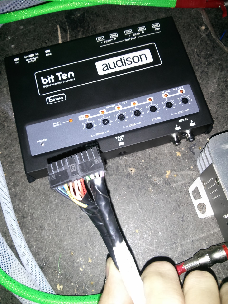
А вот вашему внимаю установленный AUDISON bit ten.
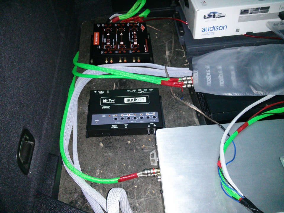
Далее подключив линейные провода, я принялся за настройку. Как вы помните BIT TEN имеет 5 выходов, а на усилителях в общем имеется 6 входов! (4 на Skar sk 125.4 и 2 на Kicx SQ 1000.1) Откуда же тогда взять еще один выход?! Выход прост) нужно установить на выход сабвуфера Y-коннектор и мы получим 2 выхода вместо 1.
Но приступим к настройке фронта! а именно Hertz SPL SHOW 200.1 и пищалки PP PT52
Выставил настройки сначала на пищалки порезав их снизу на 7000.
Так же мы можем настроить крутизну среза и тд.
Настраивается все поканально, что очень порадовало( для моей будущей 3-х полоски все очень пригодится)
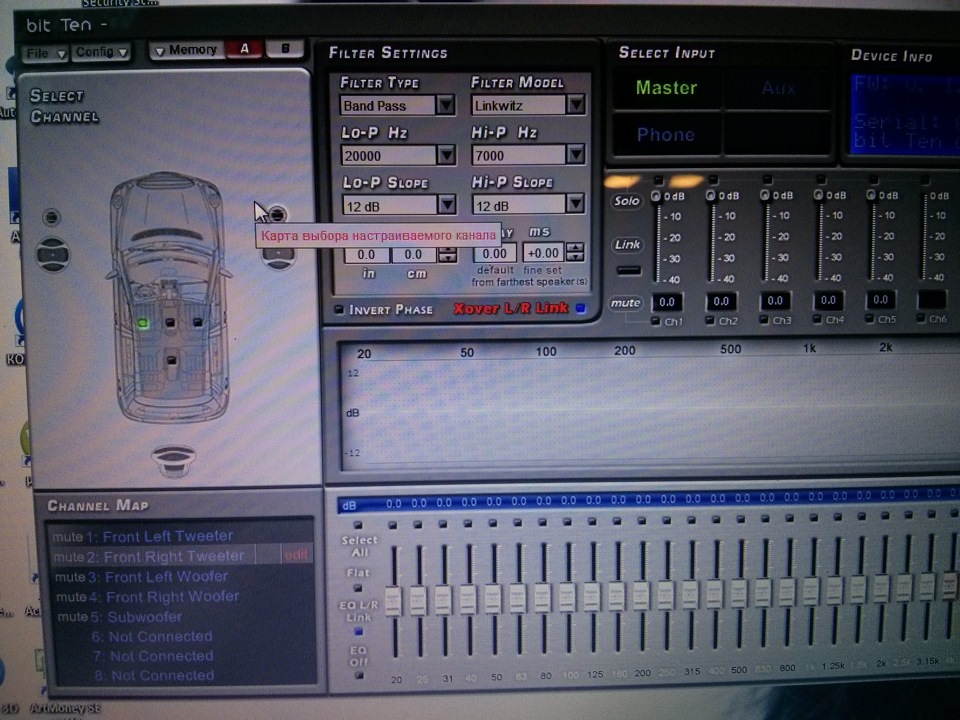
Теперь Срез мидбаса со 125 до 6500.
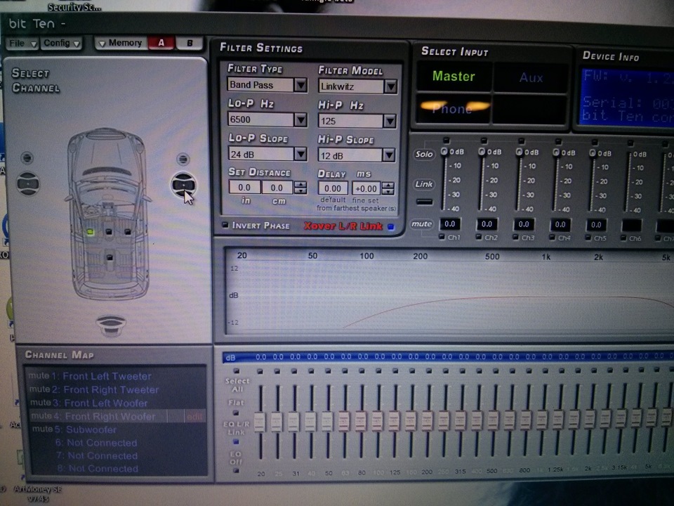
Регулировать можно все что вашей душе угодно. Включая временные задержки, но с этим я займусь завтра так как уже ночь на дворе)
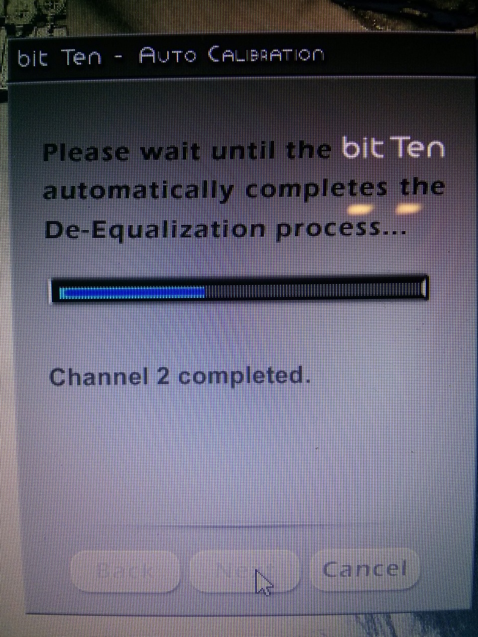
Так же в начале настройке использовался диск идущий в комплекте! на нем 5 треков для настройки. порадовало что выходной сигнал настроился по мощности сам в автоматическом режиме. Пропал небольшой фон издаваемый ГУ
Залив все настройки почему-то пропал контакт ПК-Audison и выдало такое сообщение.
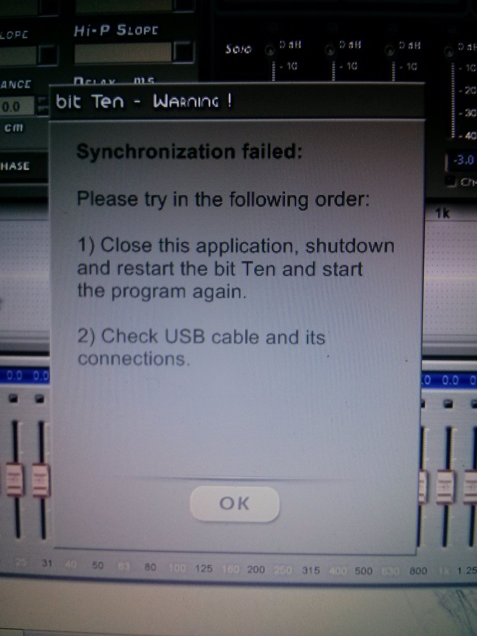
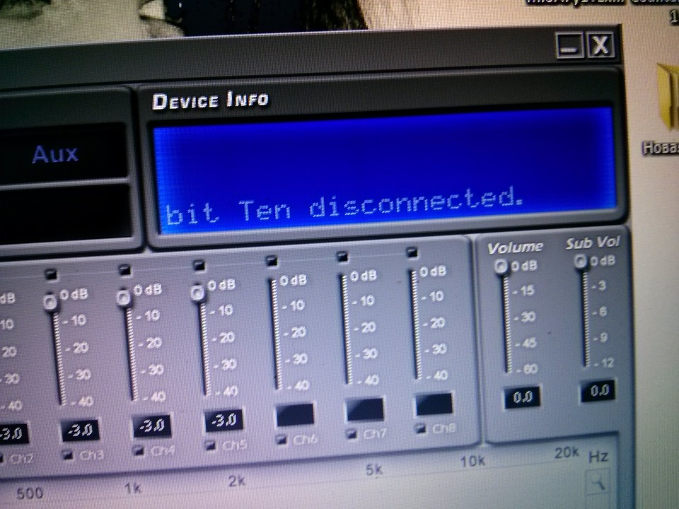
Но следуя подсказкам проблема сразу же исчезла. (думаю мои руки виноваты в этом сбое, но никак не процессор)
В общем всем спасибо! Завтра докуплю коннектор и попробую снять видео с работой аудиосистемы.
Если я сделал чтото в настройке не правильно, прошу вас тыкнуть меня в это носом)))