
| Название | Русский | English |
|---|---|---|
| RX-V492RDS OWNER’S MANUAL | — |
[639KB] |
| RX-V493 OWNER’S MANUAL | — |
[680KB] |
| RX-V493RDS OWNER’S MANUAL | — |
[688KB] |
| RX-V495 OWNER’S MANUAL | — |
[2.8MB] |
| RX-V495RDS OWNER’S MANUAL | — |
[3MB] |
| RX-V496 OWNER’S MANUAL | — |
[3.6MB] |
| RX-V496RDS OWNER’S MANUAL | — |
[3.8MB] |
| RX-V500D Easy Setup Guide | — |
[4.3MB] |
| RX-V500D Pika-asennusopas |
[4.3MB] |
[4.3MB] |
| RX-V500DOwner’s Manual | — |
[6MB] |
| RX-V520 OWNER’S MANUAL | — |
[2.7MB] |
| RX-V520RDS OWNER’S MANUAL | — |
[2.7MB] |
| RX-V530 OWNER’S MANUAL | — |
[1.3MB] |
| RX-V530RDS OWNER’S MANUAL | — |
[1.2MB] |
| RX-V540 Owner’s Manual | — |
[2.5MB] |
| RX-V550 Owner’s Manual | — |
[3MB] |
| RX-V557 Owner’s Manual | — |
[1.4MB] |
| RX-V559 Owner’s Manual | — |
[2MB] |
| RX-V563 OWNER’S MANUAL | — |
[5MB] |
| RX-V563 Owner’s Manual | — |
[4.3MB] |
| RX-V563 ИНСТРУКЦИЯ ПО ЭКСПЛУАТАЦИИ |
[5MB] |
[5MB] |
| RX-V565 OWNER’S MANUAL | — |
[2.4MB] |
| RX-V565 ИНСТРУКЦИЯ ПО ЭКСПЛУАТАЦИИ |
[2.4MB] |
[2.4MB] |
| RX-V567 / RX-V467 Safety Brochure | — |
[181KB] |
| RX-V567 / RX-V467 памятка о безопасном использовании |
[108KB] |
[181KB] |
| RX-V567 Owner’s Manual | — |
[7.3MB] |
| RX-V567 Quick Reference Guide | — |
[1.2MB] |
| RX-V567 ИНСТРУКЦИЯ ПО ЭКСПЛУАТАЦИИ |
[7.4MB] |
[7.3MB] |
| RX-V567 Краткое руководство |
[1.2MB] |
[1.2MB] |
| RX-V571 Easy Setup Guide | — |
[1.8MB] |
YAMAHA ELECTRONICS CORPORATION, USA 6660 ORANGETHORPE AVE., BUENA PARK, CALIF. 90620, U.S.A.
YAMAHA CANADA MUSIC LTD. 135 MILNER AVE., SCARBOROUGH, ONTARIO M1S 3R1, CANADA
YAMAHA ELECTRONIK EUROPA G.m.b.H. SIEMENSSTR. 22-34, 25462 RELLINGEN BEI HAMBURG, F.R. OF GERMANY
YAMAHA ELECTRONIQUE FRANCE S.A. RUE AMBROISE CROIZAT BP70 CROISSY-BEAUBOURG 77312 MARNE-LA-VALLEE CEDEX02, FRANCE
YAMAHA ELECTRONICS (UK) LTD. YAMAHA HOUSE, 200 RICKMANSWORTH ROAD WATFORD, HERTS WD18 7GQ, ENGLAND
YAMAHA SCANDINAVIA A.B. J A WETTERGRENS GATA 1, BOX 30053, 400 43 VÄSTRA FRÖLUNDA, SWEDEN
YAMAHA MUSIC AUSTRALIA PTY, LTD. 17-33 MARKET ST., SOUTH MELBOURNE, 3205 VIC., AUSTRALIA
© 2004 All rights reserved.
Printed in Malaysia
WD06160
RX-V550
AV Receiver
Ampli-tuner audio-vidéo
OWNER’S MANUAL
MODE D’EMPLOI
BEDIENUNGSANLEITUNG
BRUKSANVISNING
GEBRUIKSAANWIJZING
ИНСТРУКЦИЯ ПО ЭКСПЛУАТАЦИИ
G
RX-V550
RXV550_G_cv.fm Page 1 Wednesday, January 21, 2004 11:35 AM
Найди любой мануал:
Например: Sony VGN-FW460J/T
Вы можете бесплатно скачать Руководство по эксплуатации для Yamaha RX-V550.
Также вы сможете прочесть онлайн этот документ без скачивания.
Скачать Руководство по эксплуатации для Yamaha RX-V550
Тип файла
PDF
Размер
3.06 Mb
Кол-во страниц
78
Просмотров
8656
Читать онлайн Руководство по эксплуатации для Yamaha RX-V550 (Страница 1)

Другие Стереоресиверы Yamaha RX-V550
Топ Yamaha Стереоресиверы
Ранее вы смотрели
Эта страница полезна для вас? Поделитесь ссылкой:

RX-V550
AV Receiver
Ampli-tuner audio-vidéo
G
OWNER’S MANUAL
MODE D’EMPLOI
BEDIENUNGSANLEITUNG
BRUKSANVISNING
GEBRUIKSAANWIJZING
ИНСТРУКЦИЯ ПО ЭКСПЛУАТАЦИИ

CAUTION: READ THIS BEFORE OPERATING YOUR UNIT.
1 To assure the finest performance, please read this
manual carefully. Keep it in a safe place for future
reference.
2 Install this sound system in a well ventilated, cool,
dry, clean place — away from direct sunlight, heat
sources, vibration, dust, moisture, and/or cold.
Allow ventilation space of at least 30 cm on the top,
20 cm on the left and right, and 20 cm on the back
of this unit.
3 Locate this unit away from other electrical
appliances, motors, or transformers to avoid
humming sounds.
4 Do not expose this unit to sudden temperature
changes from cold to hot, and do not locate this
unit in a environment with high humidity (i.e. a
room with a humidifier) to prevent condensation
inside this unit, which may cause an electrical
shock, fire, damage to this unit, and/or personal
injury.
5 Avoid installing this unit where foreign object may
fall onto this unit and/or this unit may be exposed
to liquid dripping or splashing. On the top of this
unit, do not place:
– Other components, as they may cause damage
and/or discoloration on the surface of this unit.
– Burning objects (i.e. candles), as they may
cause fire, damage to this unit, and/or personal
injury.
– Containers with liquid in them, as they may fall
and liquid may cause electrical shock to the
user and/or damage to this unit.
6 Do not cover this unit with a newspaper, tablecloth,
curtain, etc. in order not to obstruct heat radiation.
If the temperature inside this unit rises, it may
cause fire, damage to this unit, and/or personal
injury.
7 Do not plug in this unit to a wall outlet until all
connections are complete.
8 Do not operate this unit upside-down. It may
overheat, possibly causing damage.
9 Do not use force on switches, knobs and/or cords.
10 When disconnecting the power cord from the wall
outlet, grasp the plug; do not pull the cord.
11 Do not clean this unit with chemical solvents; this
might damage the finish. Use a clean, dry cloth.
12 Only voltage specified on this unit must be used.
Using this unit with a higher voltage than specified
is dangerous and may cause fire, damage to this
unit, and/or personal injury. YAMAHA will not be
held responsible for any damage resulting from use
of this unit with a voltage other than specified.
13 To prevent damage by lightning, disconnect the
power cord from the wall outlet during an electrical
storm.
14 Do not attempt to modify or fix this unit. Contact
qualified YAMAHA service personnel when any
service is needed. The cabinet should never be
opened for any reasons.
15 When not planning to use this unit for long periods
of time (i.e. vacation), disconnect the AC power
plug from the wall outlet.
16 Be sure to read the “TROUBLESHOOTING” section
on common operating errors before concluding
that this unit is faulty.
17 Before moving this unit, press STANDBY/ON to set
this unit in the standby mode, and disconnect the
AC power plug from the wall outlet.
18 VOLTAGE SELECTOR (Asia and General models
only) The VOLTAGE SELECTOR on the rear panel of
this unit must be set for your local main voltage
BEFORE plugging into the AC main supply.
Voltages are:
Asia model ………………… 220/230-240 V AC, 50/60 Hz
General model . 110/120/220/230-240 V AC, 50/60 Hz
This unit is not disconnected from the AC power
source as long as it is connected to the wall outlet, even
if this unit itself is turned off. This state is called the
standby mode. In this state, this unit is designed to
consume a very small quantity of power.
WARNING
TO REDUCE THE RISK OF FIRE OR ELECTRIC
SHOCK, DO NOT EXPOSE THIS UNIT TO RAIN
OR MOISTURE.
■ For U.K. customers
If the socket outlets in the home are not suitable for the
plug supplied with this appliance, it should be cut off and
an appropriate 3 pin plug fitted. For details, refer to the
instructions described below.
Note
The plug severed from the mains lead must be destroyed, as a
plug with bared flexible cord is hazardous if engaged in a live
socket outlet.
■ Special Instructions for U.K. Model
IMPORTANT
THE WIRES IN MAINS LEAD ARE COLOURED IN
ACCORDANCE WITH THE FOLLOWING CODE:
Blue: NEUTRAL
Brown: LIVE
As the colours of the wires in the mains lead of this
apparatus may not correspond with the coloured
markings identifying the terminals in your plug,
proceed as follows:
The wire which is coloured BLUE must be connected
to the terminal which is marked with the letter N or
coloured BLACK. The wire which is coloured
BROWN must be connected to the terminal which is
marked with the letter L or coloured RED.
Making sure that neither core is connected to the earth
terminal of the three pin plug.

CONTENTS
INTRODUCTION
FEATURES……………………………………………………. 2
GETTING STARTED…………………………………….. 3
Supplied accessories ………………………………………….. 3
Installing batteries in the remote control ………………. 3
CONTROLS AND FUNCTIONS ……………………. 4
Front panel ……………………………………………………….. 4
Remote control………………………………………………….. 6
Using the remote control ……………………………………. 7
Front panel display ……………………………………………. 8
Rear panel ………………………………………………………. 10
PREPARATION
SPEAKER SETUP ……………………………………….. 11
Speaker placement …………………………………………… 11
Speaker connections ………………………………………… 12
CONNECTIONS ………………………………………….. 14
Before connecting components………………………….. 14
Connecting video components…………………………… 15
Connecting audio components…………………………… 18
Connecting the antennas …………………………………… 19
Connecting the power supply cord …………………….. 20
Turning on the power……………………………………….. 22
BASIC SETUP ……………………………………………… 23
Using the BASIC SETUP menu ………………………… 23
BASIC OPERATION
PLAYBACK…………………………………………………. 26
Basic operations………………………………………………. 26
Selecting sound field programs …………………………. 28
Selecting input modes………………………………………. 32
TUNING ………………………………………………………. 34
Automatic and manual tuning……………………………. 34
Presetting stations ……………………………………………. 35
Selecting preset stations……………………………………. 37
Exchanging preset stations ……………………………….. 38
Receiving RDS stations ……………………………………. 39
Changing the RDS mode ………………………………….. 39
PTY SEEK function ………………………………………… 40
EON function………………………………………………….. 41
RECORDING ………………………………………………. 42
SOUND FIELD PROGRAMS
SOUND FIELD PROGRAM
DESCRIPTIONS………………………………………..43
For movie/video sources…………………………………… 43
For music sources ……………………………………………. 45
ADVANCED OPERATION
ADVANCED OPERATIONS …………………………46
Using the sleep timer ……………………………………….. 46
Manually adjusting speaker levels……………………… 47
Using the test tone …………………………………………… 47
SET MENU ……………………………………………………48
Using SET MENU…………………………………………… 49
1 SOUND MENU……………………………………………. 50
2 INPUT MENU……………………………………………… 52
3 OPTION MENU…………………………………………… 53
REMOTE CONTROL FEATURES ……………….54
Control area ……………………………………………………. 54
Setting manufacturer codes……………………………….. 55
Controlling other components …………………………… 56
Clearing setup manufacturer codes…………………….. 57
ADDITIONAL INFORMATION
EDITING SOUND FIELD PARAMETERS ……58
What is a sound field ……………………………………….. 58
Changing parameter settings …………………………….. 58
SOUND FIELD PARAMETER
DESCRIPTIONS………………………………………..60
TROUBLESHOOTING …………………………………62
RESETTING THE FACTORY PRESETS ……..66
GLOSSARY…………………………………………………..67
Audio formats …………………………………………………. 67
Sound field programs……………………………………….. 68
Audio information …………………………………………… 68
Video signal information ………………………………….. 69
SPECIFICATIONS………………………………………..70
PREPARATIONINTRODUCTION
OPERATION
BASIC
SOUND FIELD
PROGRAMS
OPERATION
ADVANCED
INFORMATION
ADDITIONAL
1
English

FEATURES
FEATURES
Built-in 6-channel power amplifier
◆ Minimum RMS output power
(0.06% THD, 20 Hz – 20 kHz, 8Ω)
Front: 90 W + 90 W
Center: 90 W
Surround: 90 W + 90 W
Surround back: 90 W
Sound field features
◆ Proprietary YAMAHA technology for the creation of
sound fields
◆ Dolby Digital/Dolby Digital EX decoder
◆ DTS/DTS-ES Matrix 6.1, Discrete 6.1, DTS Neo:6,
DTS 96/24 decoder
◆ Dolby Pro Logic/Dolby Pro Logic II/Dolby Pro Logic
IIx decoder
◆ Virtual CINEMA DSP
◆ SILENT CINEMA
• y indicates a tip for your operation.
• Some operations can be performed by using either the buttons on the main unit or on the remote control. In cases when the button
names differ between the main unit and the remote control, the button name on the remote control is given in parentheses.
• This manual is printed prior to production. Design and specifications are subject to change in part as a result of improvements, etc. In
case of differences between the manual and product, the product has priority.
™
Sophisticated AM/FM tuner
◆ 40-station random access preset tuning
◆ Automatic preset tuning
◆ Preset station shifting capability (preset editing)
Other features
◆ 192-kHz/24-bit D/A converter
◆ A SET MENU which provides you with items for
optimizing this unit for your audio/video system
◆ 6 additional input jacks for discrete multi-channel input
◆ S-Video signal input/output capability
◆ Component video input/output capability
◆ Video signal conversion (Composite video ↔ S-Video)
capability for monitor out
◆ Optical and coaxial digital audio signal jacks
◆ Sleep timer
◆ Cinema and music night listening modes
◆ Remote control with preset manufacturer codes
Manufactured under license from Dolby Laboratories.
“Dolby”, “Pro Logic”, “Surround EX”, and the double-D symbol
are trademarks of Dolby Laboratories.
“SILENT CINEMA” is a trademark of YAMAHA
CORPORATION.
“DTS”, “DTS-ES”, “Neo:6” and “DTS 96/24” are trademarks of
Digital Theater Systems, Inc.
2
GETTING STARTED
GETTING STARTED
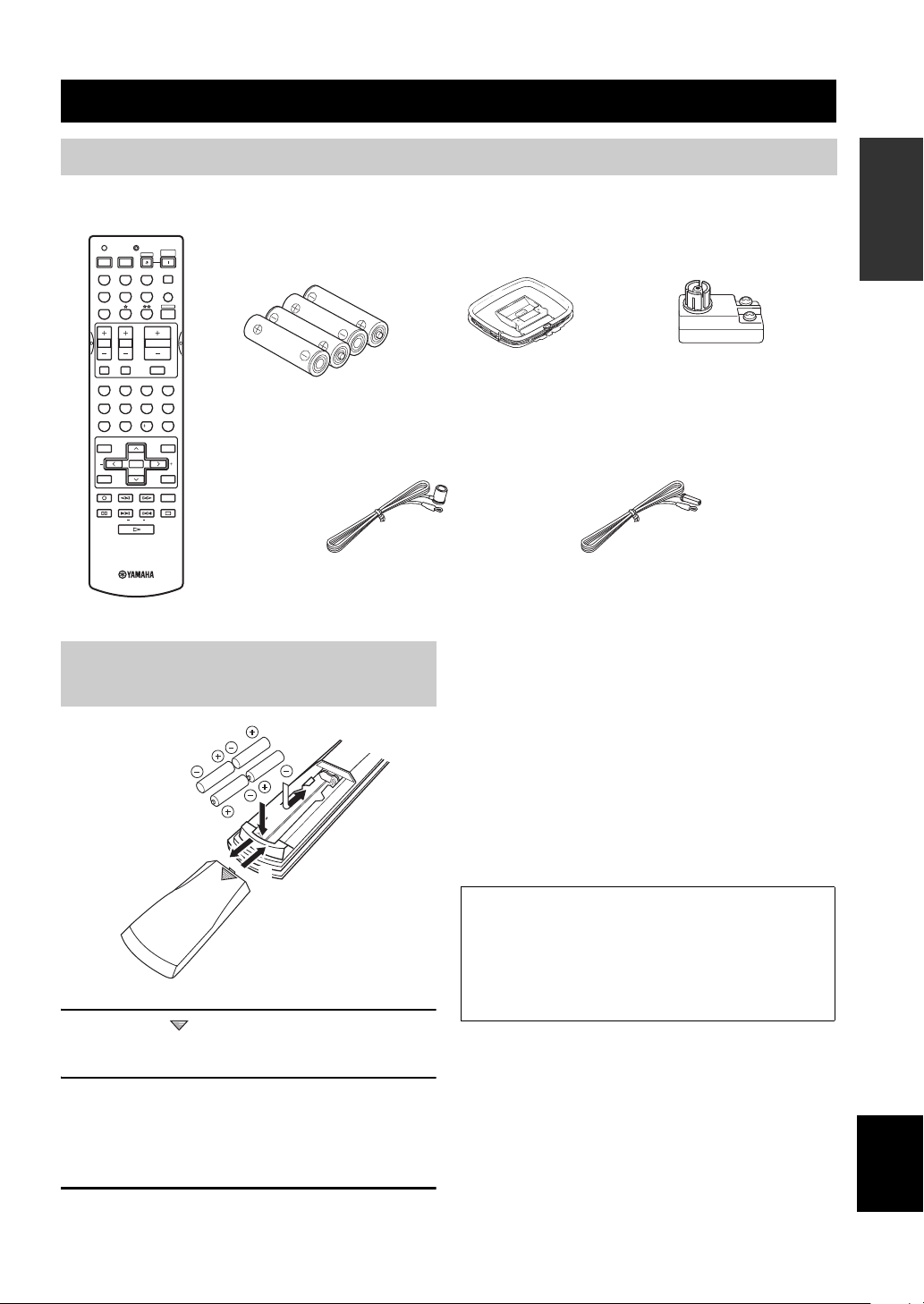
Supplied accessories
Please check that you received all of the following parts.
Remote control
TRANSMITCODE SET
CD
DVD
VCR
TV VOL TV CH
TV MUTE TV INPUT
LEVEL
TEST
REC
DISC SKIP
FREQ/RDS
MD/CD-R
DTV/CBL
SYSTEM
POWERPOWER
STANDBY
POWER
AVTV
TUNER
SLEEP
V-AUX
MULTI CH IN
AMP
VOLUME
MUTE
ROCKJAZZHALLSTEREO
4321
MOVIETV THTRMUSIC ENTERTAIN
81070965
STRAIGHT
EX/ESNIGHTq/DTS
ENTER
EFFECT
PRESET/CH
SET MENU
MENUTITLE
A/B/C/D/E
SELECT
DISPLAYRETURN
AUDIO
EONSTARTMODE PTY SEEK
RAV251
WC55290 EU
Batteries (4)
(AAA, R03, UM-4)
Indoor FM antenna
(U.S.A., Canada, China, Asia
and General models)
Installing batteries in the remote
control
2
1
3
1 Press the part and slide the battery
compartment cover off.
AM loop antenna
75-ohm/300-ohm antenna
adapter (U.K. model only)
Indoor FM antenna
(U.K., Europe, Australia
and Korea models)
Notes on batteries
• Change all of the batteries if you notice the condition like; the
operation range of the remote control decreases, the indicator
does not flash or its light becomes dim.
• Do not use old batteries together with new ones.
• Do not use different types of batteries (such as alkaline and
manganese batteries) together. Read the packaging carefully as
these different types of batteries may have the same shape and
color.
• If the batteries have leaked, dispose of them immediately. Avoid
touching the leaked material or letting it come into contact with
clothing, etc. Clean the battery compartment thoroughly before
installing new batteries.
If the remote control is without batteries for more than
2 minutes, or if exhausted batteries remain in the
remote control, the contents of the memory may be
cleared. When the memory is cleared, insert new
batteries, set up the manufacturer code and program
any acquired functions that may have been cleared.
INTRODUCTION
2 Insert four supplied batteries (AAA, R03,
UM-4) according to the polarity markings
(+ and –) on the inside of the battery
compartment.
3 Slide the cover back until it snaps into place.
English
3
CONTROLS AND FUNCTIONS
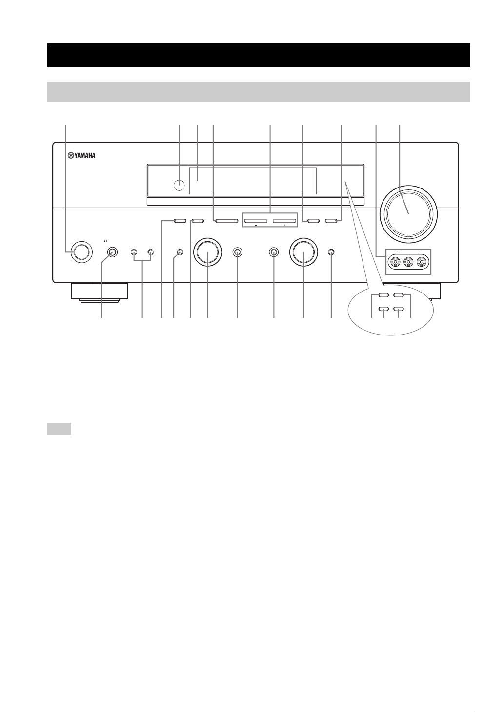
Front panel
CONTROLS AND FUNCTIONS
2134576
A/B/C/D/E
PROGRAM
EFFECT
STANDBY
/ON
PHONES
SILENT CINEMA
SPEAKERS
BA
0AC F
1 STANDBY/ON
Turns on this unit or sets it to the standby mode. When
you turn on this unit, you will hear a click and there will
be a 4 to 5-second delay before this unit can reproduce
sound.
Note
In standby mode, this unit consumes a small amount of power in
order to receive infrared-signals from the remote control.
2 Remote control sensor
Receives signals from the remote control.
3 Front panel display
Shows information about the operational status of this
unit.
4 A/B/C/D/E (NEXT)
Selects one of the 5 preset station groups (A to E) when
the unit is in tuner mode.
Selects the speaker channel to be adjusted when the unit is
not in tuner mode.
9
8
(U.S.A. model)
VOLUME
l PRESET/TUNING h
INPUT MODETONE CONTROLSTRAIGHT
GHIEDB
MEMORYFM/AMPRESET/TUNING
TUNING MODE
AUTO/MAN’L MONOMAN’L/AUTO FMLEVELNEXTEDIT
INPUT
MULTI CH
INPUT
VIDEO L AUDIO R
RDS MODE/FREQ EON
PTY SEEK
MODE
VIDEO AUX
START
KLMJ
(U.K. and Europe models only)
5 PRESET/TUNING l / h (LEVEL –/+)
Selects preset station number 1 to 8 when the colon (:) is
displayed next to the band indication in the front panel
display when the unit is in tuner mode. Selects the tuning
frequency when the colon (:) is not displayed.
Adjusts the level of the speaker channel selected using
A/B/C/D/E (NEXT) when the unit is not in tuner mode.
6 MEMORY (MAN’L/AUTO FM)
Stores a station in the memory. Hold down this button for
more than 3 seconds to start automatic preset tuning.
7 TUNING MODE (AUTO/MAN’L MONO)
Switches between automatic tuning (AUTO indicator on)
and manual tuning (AUTO indicator off).
8 VIDEO AUX jacks
Input audio and video signals from a portable external
source such as a game console. To reproduce source
signals from these jacks, select V-AUX as the input source.
9 VOLUME
Controls the output level of all audio channels.
This does not affect the REC OUT level.
4

CONTROLS AND FUNCTIONS
0 PHONES (SILENT CINEMA) jack
Outputs audio signals for private listening with
headphones. When you connect headphones, no signals
are output to the OUTPUT jacks or to the speakers.
All Dolby Digital and DTS audio signals are mixed down
to the left and right headphone channels.
A SPEAKERS A/B
Turns on or off the set of front speakers connected to the A
and/or B terminals on the rear panel each time the
corresponding button is pressed.
B PRESET/TUNING (EDIT)
Switches the function of PRESET/TUNING l / h
(LEVEL –/+) between selecting preset station numbers
and tuning.
C STRAIGHT (EFFECT)
Switches the sound fields off or on. When STRAIGHT is
selected, input signals (2-channel or multi-channel) are
output directly from their respective speakers without
effect processing.
D FM/AM
Switches the reception band between FM and AM.
E PROGRAM
Use to select sound field programs or adjust the bass/
treble balance (in conjunction with TONE CONTROL).
F TONE CONTROL
Use to adjust the bass/treble balance for the front left and
right speakers (see page 27).
G INPUT MODE
Sets the priority (AUTO, DTS, ANALOG) for the type of
signals received when one component is connected to two
or more of this unit’s input jacks (see page 32).
H INPUT selector
Selects the input source you want to listen to or watch.
■ U.K. and Europe models only
J RDS MODE/FREQ
Press this button when the unit is receiving an RDS station
to cycle the display between the PS mode, PTY mode, RT
mode, CT mode (if the station offers those RDS data
services) and/or the frequency display.
K PTY SEEK MODE
Press this button to set the unit to the PTY SEEK mode.
L PTY SEEK START
Press this button to begin searching for a station after the
desired program type has been selected in the PTY SEEK
mode.
M EON
Press this button to select a radio program type (NEWS,
INFO, AFFAIRS, SPORT) to tune in automatically.
INTRODUCTION
I MULTI CH INPUT
Selects the source connected to the MULTI CH INPUT
jacks. When selected, the MULTI CH INPUT source takes
priority over the source selected with INPUT (or the input
selector buttons on the remote control).
English
5
CONTROLS AND FUNCTIONS
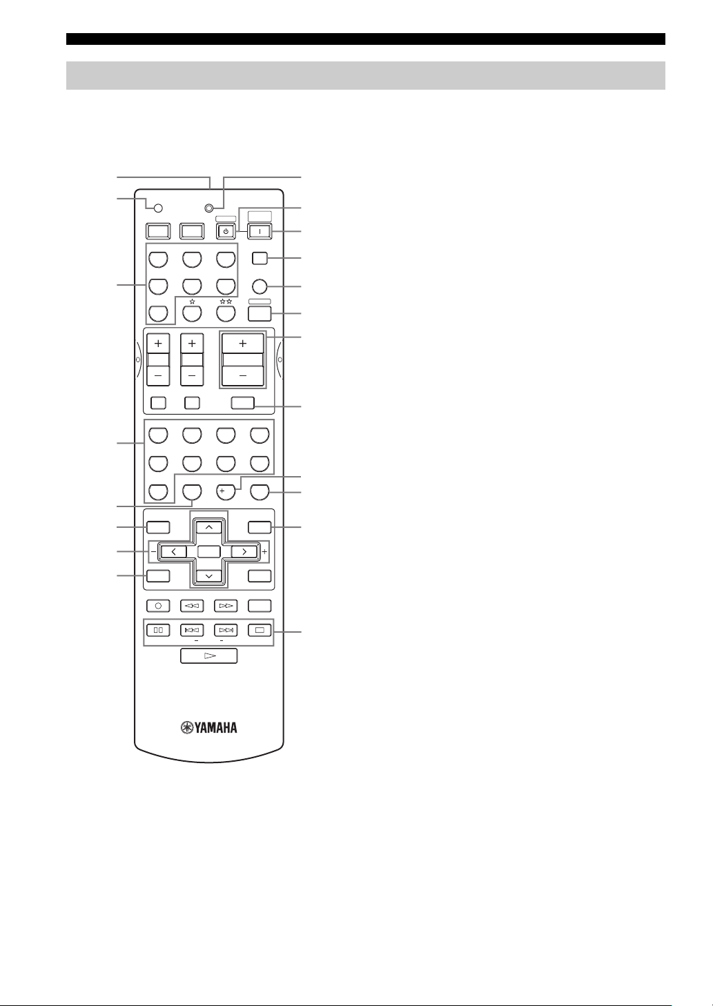
Remote control
This section describes the function of each control on the
remote control used to control this unit. To operate other
components, see “REMOTE CONTROL FEATURES” on
page 54.
1
2
TRANSMITCODE SET
POWERPOWER
AVTV
CD
MD/CD-R
STANDBY
TUNER
SYSTEM
POWER
SLEEP
9
0
A
B
DTV/CBL
V-AU X
MULTI CH IN
C
AMP
3
DVD
VCR
D
E
65
09
PRESET/CH
SELECT
EX/ESNIGHTq/DTS
VOLUME
7
10
MUTE
ROCKJAZZHALLSTEREO
4321
MOVIETV THTRMUSIC ENTERTAIN
8
STRAIGHT
ENTER
EFFECT
SET MENU
MENUTITLE
A/B/C/D/E
DISPLAYRETURN
AUDIO
EONSTART
F
G
H
I
J
4
5
6
7
8
TV VOL TV CH
TV MUTE TV INPUT
LEVEL
TEST
REC
DISC SKIP
MODE PTY SEEK
FREQ/RDS
3 Input selector buttons
Select the input source and change the control area.
4 Sound field program / numeric buttons
Use to select sound field programs.
Use numbers 1 through 8 to select preset stations when the
unit is in tuner mode.
5 NIGHT
Turns on or off the night listening modes (page 31).
6 LEVEL
Selects the speaker channel to be adjusted and sets the
level.
7 Cursor buttons u / d / j / i / SELECT
Use to select and adjust sound field program parameters or
SET MENU items.
Press u / d to select preset station numbers when the unit
is in tuner mode.
8 TEST (RETURN)
Outputs the test tone to adjust the speaker levels.
Returns to the previous menu level when adjusting the
SET MENU parameters.
9 TRANSMIT indicator
Flashes while the remote control is sending signals.
0 STANDBY
Sets this unit in the standby mode.
A SYSTEM POWER
Turns on the power of this unit.
B SLEEP
Sets the sleep timer.
C MULTI CH IN
Selects MULTI CH INPUT when using an external
decoder (etc.).
D AMP
Selects the AMP mode. You must select the AMP mode to
control the main unit.
1 Infrared window
Outputs infrared control signals. Aim this window at the
component you want to operate.
2 CODE SET
Use to set up manufacturer codes (see page 55).
6
E VOLUME –/+
Increases or decreases the volume level.
F MUTE
Mutes the sound. Press again to restore the audio output to
the previous volume level.
G EX/ES
Switches between 5.1 or 6.1-channel playback of multichannel software.
H STRAIGHT (EFFECT)
Switches the sound fields off or on. When STRAIGHT is
selected, input signals (2-channel or multi-channel) are
output directly from their respective speakers without
effect processing.
I SET MENU (A/B/C/D/E)
Activates the SET MENU function.
Selects preset station groups when the unit is in tuner
mode.
■ U.K. and Europe models only
J RDS tuning buttons
FREQ/RDS
Press this button when the unit is receiving an RDS station
to cycle the display between the PS mode, PTY mode, RT
mode, CT mode (if the station offers those RDS data
service) and/or the frequency display.
PTY SEEK MODE
Press this button to set the unit to the PTY SEEK mode.
PTY SEEK START
Press this button to begin searching for a station after the
desired program type has been selected in the PTY SEEK
mode.
EON
Press this button to select a radio program type (NEWS,
INFO, AFFAIRS, SPORT) to tune in automatically.
CONTROLS AND FUNCTIONS
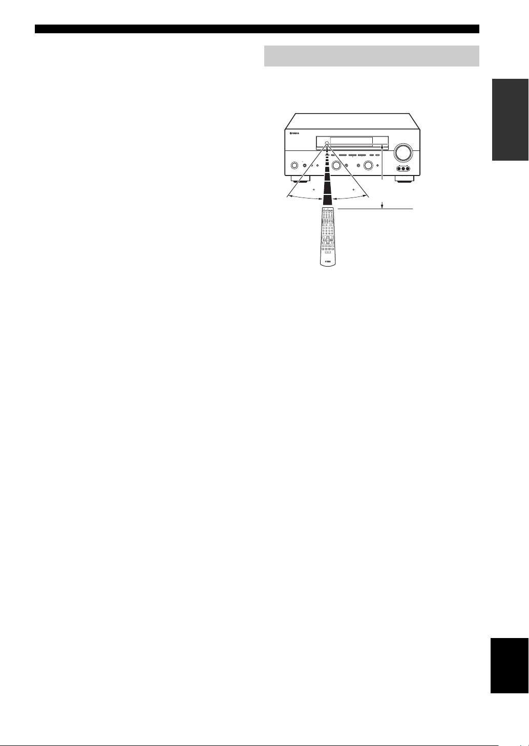
Using the remote control
The remote control transmits a directional infrared beam.
Be sure to aim the remote control directly at the remote
control sensor on the main unit during operation.
RDS MODE/FREQ EON
VOLUME
PTY SEEK
MODE
START
MEMORYFM/AMPRESET/TUNING
A/B/C/D/E
l PRESET/TUNING h
TUNING MODE
/ON
EFFECT
SILENT CINEMA
PROGRAM
PHONES
SPEAKERS
BA
STANDBY
30 30
TRANSMITCODE SET
SYSTEM
POWERPOWER
STANDBY
POWER
AVTV
CD
MD/CD-R
TUNER
SLEEP
V-AUX
DVD
DTV/CBL
MULTI CH IN
VCR
AMP
VOLUME
TV VOL TV CH
TV MUTE TV INPUT
MUTE
ROCKJAZZHALLSTEREO
4321
MOVIETV THTRMUSICENTERTAIN
81070965
EX/ESNIGHTq/DTS
STRAIGHT
ENTER
EFFECT
PRESET/CH
LEVEL
SET MENU
MENUTITLE
A/B/C/D/E
SELECT
TEST
DISPLAYRETURN
REC
AUDIO
DISC SKIP
■ Handling the remote control
• Do not spill water or other liquids on the remote
control.
• Do not drop the remote control.
• Do not leave or store the remote control in the
following types of conditions:
– high humidity such as near a bath
– high temperature such as near a heater or stove
– extremely low temperatures
– dusty places
AUTO/MAN’L MONOMAN’L/AUTO FMLEVELNEXTEDIT
INPUT
INPUT MODETONE CONTROLSTRAIGHT
MULTI CH
INPUT
VIDEO AUX
VIDEO L AUDIO R
Approximately 6 m
INTRODUCTION
7
English
CONTROLS AND FUNCTIONS
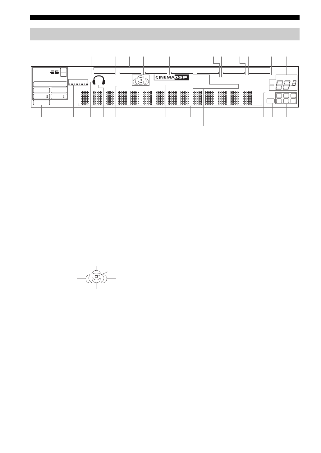
Front panel display
123456 780AB9
t
MATRIX DISCRETE
q
DIGITAL
q
q
EX
q
PL
q
PCM
PL x
96
24
SILENT CINEMA NIGHT PTY HOLD AUTO
VIRTUAL
PL
SP
A B
V-A UXVCR
SLEEP
DTV/CBL
FG
1 Decoder indicators
When any of this unit’s decoders function, the respective
indicator lights up.
2 SILENT CINEMA indicator
Lights up when headphones are connected and a sound
field program is selected (see page 27).
3 NIGHT indicator
Lights up when you select night listening mode.
4 Input source indicators
A cursor lights to show the current input source.
5 Sound field indicators
Light to indicate the active DSP sound fields.
CDTUNER
MEMORY
ft
mS
dB
96/24
LFE
HiFi DSP
DVD
MD/CD-R
TUNED STEREO MUTE
PS RT CT EONPTY
HI KLJEDC
(U.K. and Europe models only)
M
0 MEMORY indicator
Blinks to show that a station can be stored.
A MUTE indicator
Blinks while the MUTE function is on.
B VOLUME level indication
Indicates the volume level.
C PCM indicator
Lights up when this unit is reproducing PCM (pulse code
modulation) digital audio signals.
D VIRTUAL indicator
Lights up when Virtual CINEMA DSP is active (see
page 32).
VOLUME
dB
LCR
SL SB SR
Presence DSP sound field
Listening position
Left surround
DSP sound field
Surround back DSP sound field
Right surround
DSP sound field
6 CINEMA DSP indicator
Lights up when you select a CINEMA DSP sound field
program.
7 AUTO indicator
Lights up to indicate that automatic tuning is possible.
8 TUNED indicator
Lights up when this unit is tuned into a station.
9 STEREO indicator
Lights up when this unit is receiving a strong signal for an
FM stereo broadcast while the AUTO indicator is lit.
8
E Headphones indicator
Lights up when headphones are connected.
F SP A B indicators
Light up according to the set of front speakers selected.
Both indicators light up when both sets of speakers are
selected.
G SLEEP indicator
Lights up while the sleep timer is on.
H HiFi DSP indicator
Lights up when you select a HiFi DSP sound field
program.
I Multi-information display
Shows the current sound field program name and other
information when adjusting or changing settings.
J 96/24 indicator
Lights up when a DTS 96/24 signal is input to this unit.

K LFE indicator
Lights up when the input signal contains the LFE signal.
L Input channel indicators/speaker indicators
Indicate the channel components of the current digital
input signal.
Indicate the number of speakers connected in SPEAKERS
(page 24), or indicate the channel being adjusted in SP
LEVEL (page 51).
M RDS indicators
(U.K. and Europe models only)
The name(s) of the RDS data offered by the currently
received RDS station light(s) up.
EON lights up when an RDS station that offers the EON
data service is being received.
PTY HOLD lights up while searching for stations in the
PTY SEEK mode.
CONTROLS AND FUNCTIONS
INTRODUCTION
9
English
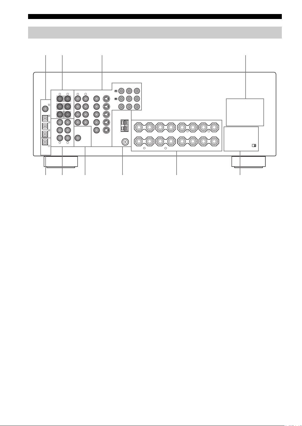
CONTROLS AND FUNCTIONS
Rear panel
12 3 4
DIGITAL
INPUT
COAXIAL
OPTICAL
DTV/CBL
DVD
MD/CD-R
MD/CD-R
OPTICAL
DIGITAL
OUTPUT
COMPONENT VIDEO
MULTI CH INPUT
R
FRONT
SURROUND
CD
SUB
WOOFER
CD
IN
(
)
PLAY
MD
/CD-R
OUT
(
)
REC
R
AUDIO
AUDIO
L
L
CENTER
L
VIDEO
R
DVD
DTV
/CBL
IN
VCR
OUT
VIDEO
SUB
WOOFER
OUTPUT
VIDEO
MONITOR OUT
S VIDEO
S VIDEO
DVD
DTV
/CBL
MONITOR
OUT
TUNER
AM
ANT
GND
FM
ANT
P
R
75Ω UNBAL.
Y
P
B
+
+
1 DIGITAL INPUT jacks
See pages 15, 17 and 18 for details.
2 MULTI CH INPUT jacks
See page 16 for connection information.
3 Video component jacks
See pages 15 and 17 for connection information.
4 AC OUTLET(S)
Use to supply power to your other A/V components (see
page 20).
5 DIGITAL OUTPUT jack
See page 18 for details.
6 Audio component jacks
See page 18 for connection information.
–
+
+
SPEAKERS
–
A
B
+
–
–
FRONT
R
+
L
CENTER
––
R
SURROUND
–
–
SURROUND BACK
L
7 SUB WOOFER OUTPUT jack
See page 13 for connection information.
8 Antenna terminals
See page 19 for connection information.
9 Speaker terminals
See page 13 for connection information.
0 IMPEDANCE SELECTOR switch
See page 21.
< Asia and General models only >
FREQUENCY STEP switch
See page 19.
VOLTAGE SELECTOR
See page 20.
+
IMPEDANCE SELECTOR
+
10
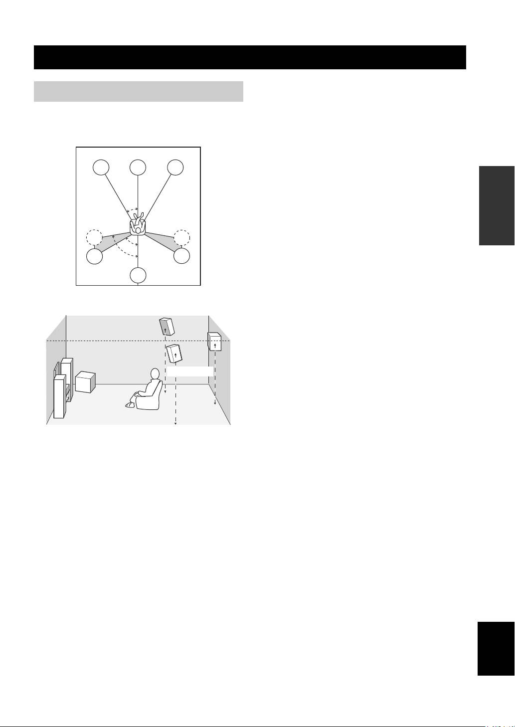
SPEAKER SETUP
SPEAKER SETUP
Speaker placement
The speaker layout below shows the standard ITU-R
speaker setting. You can use it to enjoy CINEMA DSP
and multi-channel audio sources.
FL
SL
SL
C
30˚
60˚
80˚
SB
FR
SR
SR
1.8 m
Surround speakers (SR and SL)
The surround speakers are used for effect and surround
sounds. Place these speakers behind your listening
position, facing slightly inwards, about 1.8 m above the
floor.
Surround back speaker (SB)
The surround back speaker supplements the surround
speakers and provides for more realistic front-to-back
transitions. Place this speaker directly behind the listening
position and at the same height as the surround speakers.
Subwoofer
The use of a subwoofer, such as the YAMAHA Active
Servo Processing Subwoofer System, is effective not only
for reinforcing bass frequencies from any or all channels,
but also for high fidelity reproduction of the LFE (lowfrequency effect) channel included in Dolby Digital and
DTS software. The position of the subwoofer is not so
critical, because low bass sounds are not highly
directional. But it is better to place the subwoofer near the
front speakers. Turn it slightly toward the center of the
room to reduce wall reflections.
PREPARATION
Front speakers (FR and FL)
The front speakers are used for the main source sound plus
effect sounds. Place these speakers an equal distance from
the ideal listening position. The distance of each speaker
from each side of the video monitor should be the same.
Center speaker (C)
The center speaker is for the center channel sounds
(dialog, vocals, etc.). If for some reason it is not practical
to use a center speaker, you can do without it. Best results,
however, are obtained with the full system. Align the front
face of the center speaker with the front face of your video
monitor. Place the speaker centrally between the front
speakers and as close to the monitor as possible, such as
directly over or under it.
English
11
SPEAKER SETUP
Speaker connections
Be sure to connect the left channel (L), right channel (R),
“+” (red) and “–” (black) properly. If the connections are
faulty, no sound will be heard from the speakers, and if the
polarity of the speaker connections is incorrect, the sound
will be unnatural and lack bass.
CAUTION
• If you will use 6 ohm speakers, be sure to set
this unit’s speaker impedance setting to 6
ohms before using (see page 21).
• Before connecting the speakers, make sure that the
power of this unit is off.
• Do not let the bare speaker wires touch each other or
do not let them touch any metal part of this unit. This
could damage this unit and/or speakers.
• Use magnetically shielded speakers. If this type of
speakers still creates the interference with the monitor,
place the speakers away from the monitor.
A speaker cord is actually a pair of insulated cables
running side by side. One cable is colored or shaped
differently, perhaps with a stripe, groove or ridges.
Connect the striped (grooved, etc.) cable to the “+” (red)
terminals on this unit and your speaker. Connect the plain
cable to the “–” (black) terminals.
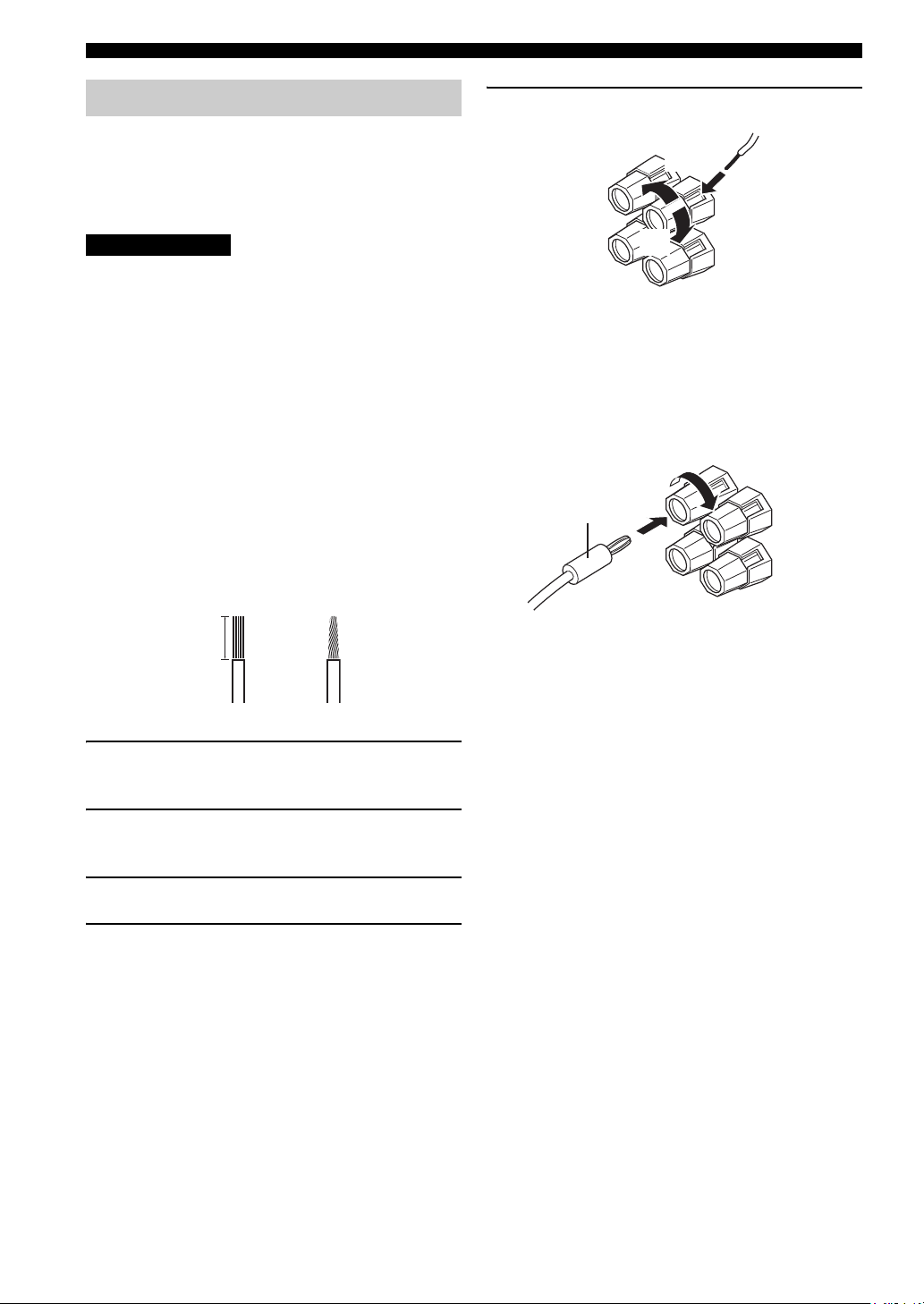
10 mm
5 Tighten the knob to secure the wire.
3
4
5
Red: positive (+)
Black: negative (–)
■ Banana plug connections
(With the exception of U.K., Europe and Asia models)
First, tighten the knob and then insert the banana plug
connector into the end of the corresponding terminal.
Banana plug
(With the exception of U.K., Europe
and Asia models)
1
2
1 Remove approximately 10 mm of insulation
from the end of each speaker cable.
2 Twist the exposed wires of the cable together
to prevent short circuits.
3 Unscrew the knob.
4 Insert one bare wire into the hole in the side
of each terminal.
12
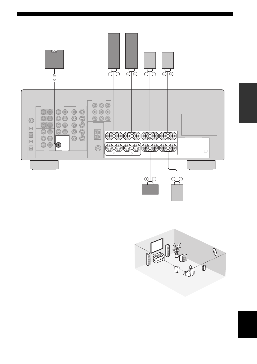
Front speakers (A)
LeftRight
SPEAKER SETUP
Subwoofer
system
SUB
WOOFER
OUTPUT
Surround speakers
LeftRight
2 3 6 71
PREPARATION
+
+
–
A
B
–
FRONT
R
SPEAKERS
–
–
+
+
+
+
L
CENTER
––
R
SURROUND
–
–
L
SURROUND BACK
+
+
speakers
■ FRONT terminals
Connect one or two speaker systems to these terminals. If
you use only one speaker system, connect it to either the
FRONT A or B terminals.
■ CENTER terminals
Connect a center speaker to these terminals.
■ SURROUND terminals
Connect surround speakers to these terminals.
■ SUB WOOFER jack
Connect a subwoofer with built-in amplifier, such as the
YAMAHA Active Servo Processing Subwoofer System,
to this jack.
■ SURROUND BACK terminals
Connect a surround back speaker to these terminals.
Front
(B)
Center
speaker
3
Surround back
4
54
speaker
2
1
7
Speaker layout
6
5
English
13
CONNECTIONS
CONNECTIONS
Before connecting components
CAUTION
Do not connect this unit or other components to the mains
power until all connections between components are
complete.
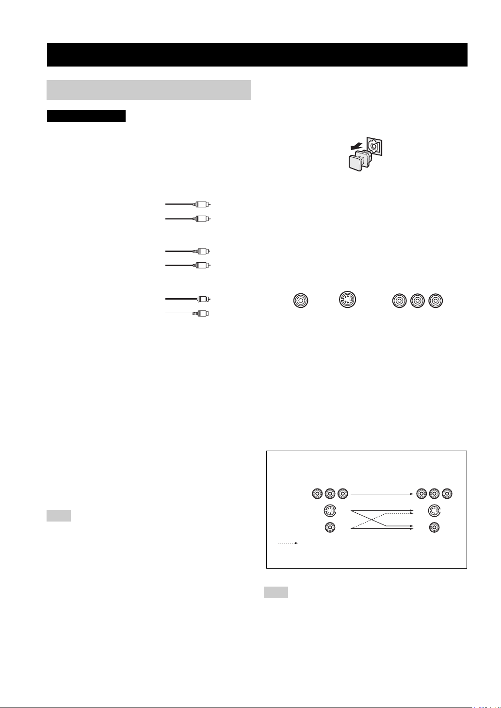
■ Cable indications
Dust protection cap
Pull out the cap from the optical jack before you connect
the fiber optic cable. Do not discard the cap. When you are
not using the optical jack, be sure to put the cap back in
place. This cap protects the jack from dust.
For analog signals
left analog cables
right analog cables
For digital signals
optical cables
coaxial cables
For video signals
video cables
S-Video cables
L
R
O
C
V
S
V
■ Analog jacks
You can input analog signals from audio components by
connecting audio pin cable to the analog jacks on this unit.
Connect red plugs to the right jacks and white plugs to the
left jacks.
■ Digital jacks
This unit has digital jacks for direct transmission of digital
signals through either coaxial or fiber optic cables. You
can use the digital jacks to input PCM, Dolby Digital and
DTS bitstreams. When you connect components to both
the COAXIAL and OPTICAL jacks, priority is given to
the input signals from the COAXIAL jack. All digital
input jacks are compatible with 96-kHz sampling digital
signals.
Note
This unit handles digital and analog signals independently. Thus
audio signals input to the analog jacks are only output to the
analog OUT (REC) jacks. Likewise audio signals input to the
digital (OPTICAL or COAXIAL) jacks are only output to the
DIGITAL OUTPUT jack.
■ Video jacks
This unit has three types of video jacks. Connection
depends on the availability of input jacks on your monitor.
The signals input through the S VIDEO jacks on this unit
are automatically converted for output through the
VIDEO jacks. When V CONV. is set to ON (see page 53),
signals input through the VIDEO jacks can be output
through the S VIDEO jacks.
VIDEO
S VIDEO
VIDEO jack
For conventional composite video signals.
S VIDEO jack
For S-Video signals, separated into luminance (Y) and
color (C) video signals to achieve high-quality color
reproduction.
COMPONENT VIDEO jacks
For component signals, separated into luminance (Y) and
color difference (P
B, PR) to provide the best quality in
picture reproduction.
Signal flow inside this unit
Input
COMPONENT
VIDEO
S VIDEO
VIDEO
Only when V CONV. is set to ON
(see page 53).
COMPONENT VIDEO
PR PB Y
Output
(MONITOR OUT)
14
Note
When signals are input through both the S VIDEO and VIDEO
jacks, signals input through the S VIDEO jack have priority.
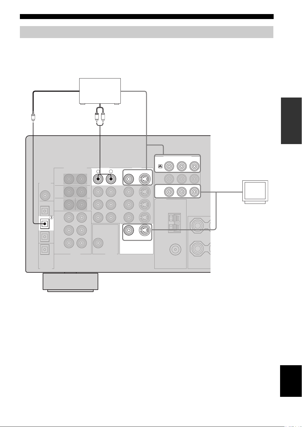
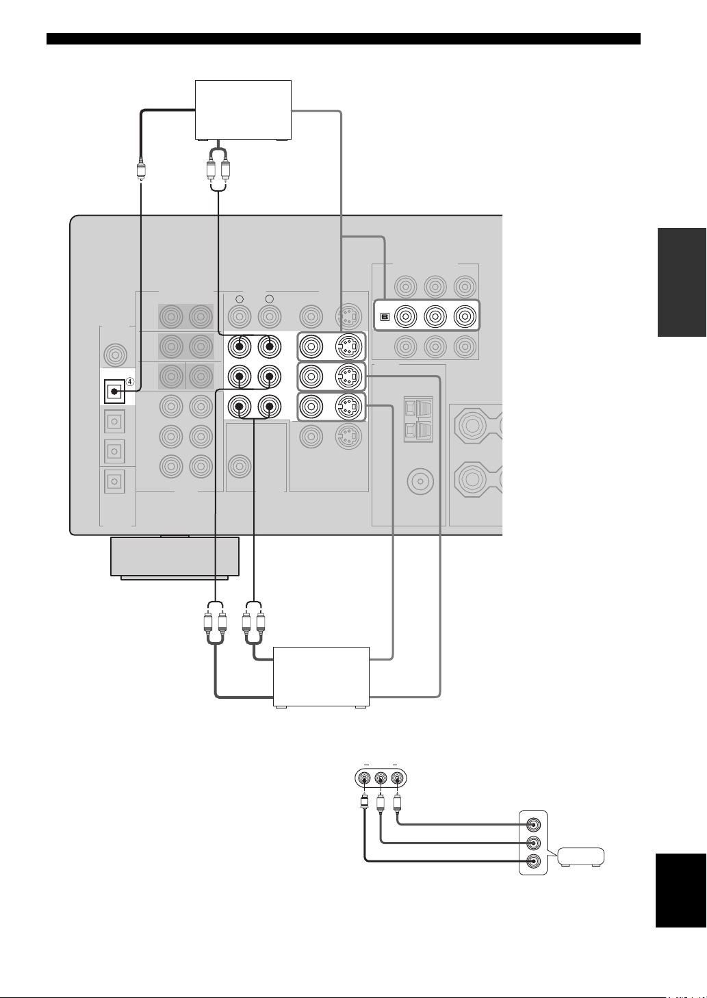
Connecting video components
■ Connections for DVD playback
CONNECTIONS
Optical out
DVD player
Video out
PREPARATION
Audio out
R
LR
AUDIO
COMPONENT VIDEO
PR
S VIDEO
S VIDEO
DVD
MONITOR
OUT
DVD
VIDEO
VIDEO
MONITOR OUT
VIDEO
L
Y
PB
Video in
Video
monitor
O
DVD
15
English
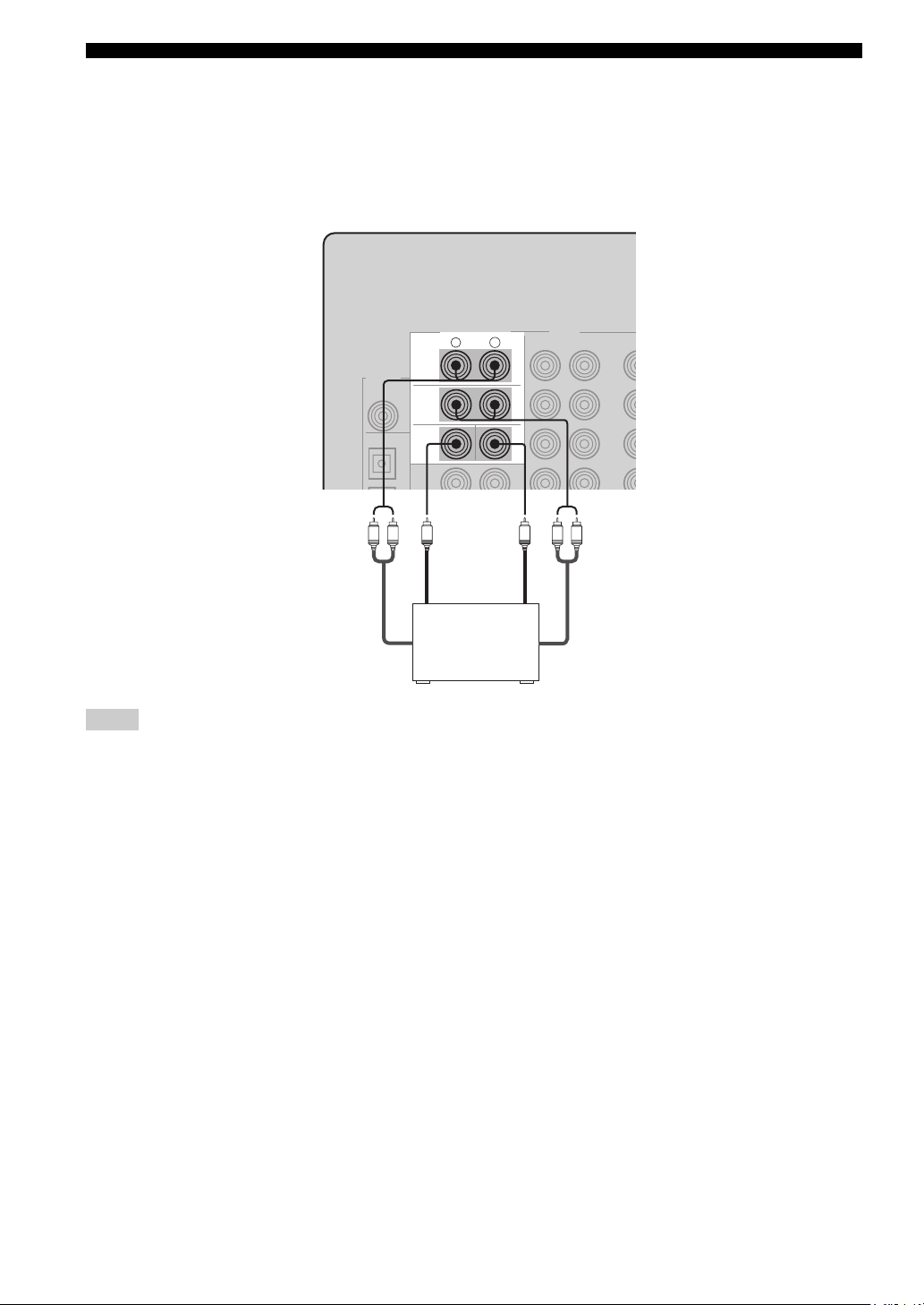
CONNECTIONS
■ Connecting to the MULTI CH INPUT jacks
This unit is equipped with 6 additional input jacks (left and right FRONT, CENTER, left and right SURROUND and
SUB WOOFER) for discrete multi-channel input from a multi-format player, external decoder, sound processor or preamplifier.
Connect the output jacks on your multi-format player or external decoder to the MULTI CH INPUT jacks. Be sure to
match the left and right outputs to the left and right input jacks for the front and surround channels.
MULTI CH INPUT
R
L
FRONT
SURROUND
SUB
WOOFER
CENTER
LR
Subwoofer
LR
out
Center
out
Multi-format player/
External decoder
Front
out
Surround
out
Notes
• When you select MULTI CH INPUT as the input source, this unit automatically turns off the digital sound field processor, and you
cannot select sound field programs.
• This unit does not redirect signals input to the MULTI CH INPUT jacks to accommodate for missing speakers. We recommend that
you connect at least a 5.1-channel speaker system before using this feature.
• When headphones are used, only front left and right channels are output.
16
■ Connections for other video components
CONNECTIONS
DIGITAL
INPUT
COAXIAL
OPTICAL
DTV/CBL
O
CD
Optical out
Audio out
Cable TV or
satellite tuner
LR
AUDI O
R
Video out
PREPARATION
COMPONENT VIDEO
PB Y
PR
VIDEO
VIDEO
S VIDEO
DTV
/CBL
L
DTV
/CBL
IN
VCR
OUT
LR LR
Audio in
Audio out Video out
DVD recorder
or VCR
■ VIDEO AUX jacks (on the front panel)
Use these jacks to connect any video source, such as a
game console or video camera, to this unit.
Video in
VIDEO AUX
VIDEO L AUDIO R
V
L
R
Game
Audio out R
Audio out L
Video out
console or
video camera
English
17
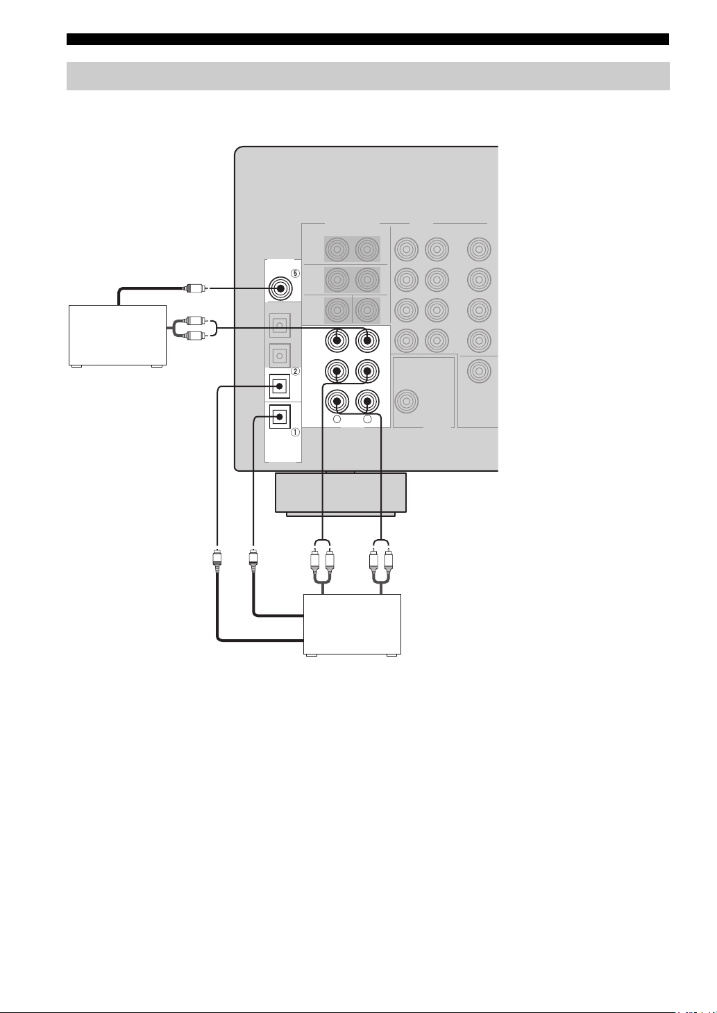
CONNECTIONS
Connecting audio components
■ Connections for audio components
DIGITAL
INPUT
COAXIAL
CD
CD player
Coaxial out
C
Audio out
L
R
CD
Audio out
IN
(
)
PLAY
MD
/CD-R
(
)
REC
R
L
AUDI O
LR LR
MD recorder or
tape deck
Audio in
MD/CD-R
MD/CD-R
OPTICAL
DIGITAL
OUTPUT
O
O
Optical in
Optical out
18
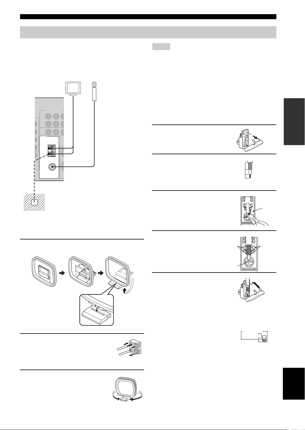
Connecting the antennas
CONNECTIONS
Both AM and FM indoor antennas are included with this
unit. In general, these antennas should provide sufficient
signal strength. Connect each antenna correctly to the
designated terminals.
AM loop antenna
(included)
TUNER
AM
ANT
GND
75Ω UNBAL.
FM
ANT
Ground (GND terminal)
For maximum safety and minimum interference,
connect the antenna
ground. A good earth ground is a metal stake driven
into moist earth.
Indoor FM antenna
(included)
GND terminal to a good earth
Notes
• The AM loop antenna should be placed away from this unit.
• The AM loop antenna should always be connected, even if an
outdoor AM antenna is connected to this unit.
• A properly installed outdoor antenna provides clearer reception
than an indoor one. If you experience poor reception quality, an
outdoor antenna may improve the quality. Consult the nearest
authorized YAMAHA dealer or service center about outdoor
antennas.
■ 75-ohm/300-ohm antenna adapter
(U.K. model only)
1 Open the cover of the
included 75-ohm/300-ohm
antenna adapter.
2 Cut the external sleeve
of the 75-ohm coaxial
cable and prepare it for
11 mm
8 mm
6 mm
connection.
3 Cut the lead wire and
remove it.
Lead wire
PREPARATION
■ Connecting the AM loop antenna
1 Set up the AM loop antenna, then connect it
to the terminals on this unit.
2 Press and hold the tab to insert
the AM loop antenna lead wires
into the AM ANT and GND
terminals.
3 Orient the AM loop antenna
for the best reception.
4 Insert the cable
wire into the slot,
and clamp it with
pliers.
Clamp
Insert wire into
slot.
Clamp
5 Snap the cover
into place.
■ FREQUENCY STEP switch
(Asia and General models only)
Because the interstation frequency
spacing differs in different areas, set
the FREQUENCY STEP switch
(locating on the rear panel) according
to the frequency spacing in your area.
• North, Central and South America: 100 kHz/10 kHz
• Other areas: 50 kHz/9 kHz
Before setting this switch, disconnect this unit’s power
cord from the AC wall outlet.
FREQUENCY STEP
10KHZ / 100KH
Z
FMAM
9KHZ / 50KH
Z
English
19
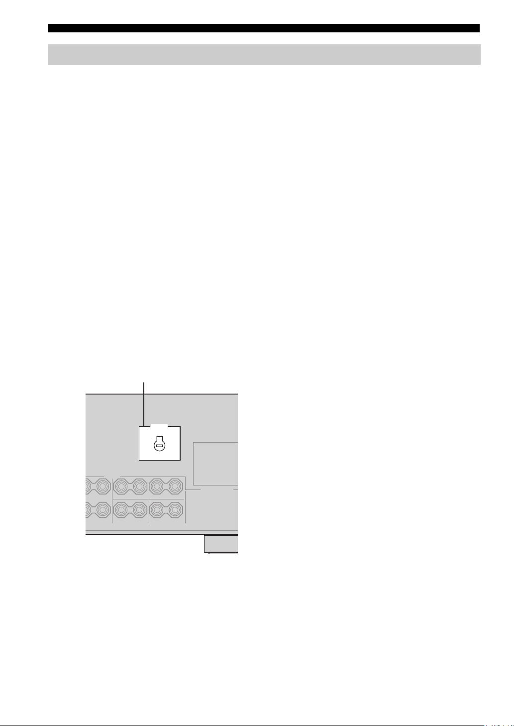
CONNECTIONS
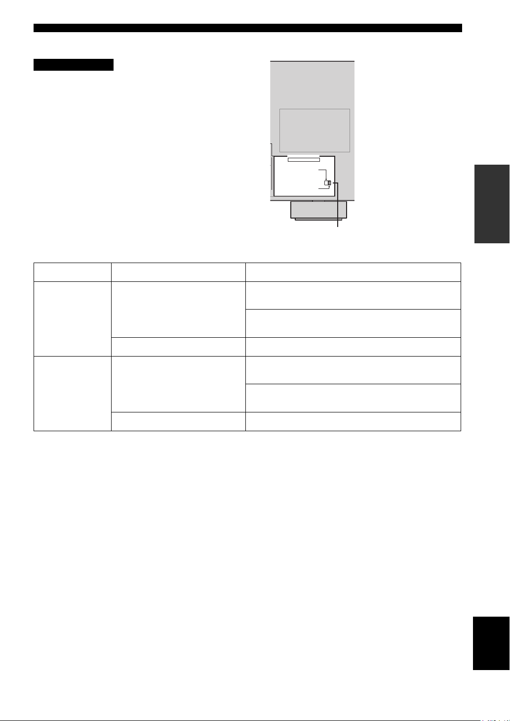
Connecting the power supply cord
■ Connecting the AC power cord
Plug the power cord into an AC wall outlet.
■ AC OUTLET(S) (SWITCHED)
U.K. and Australia models ………………………… 1 OUTLET
Korea model ………………………………………………………None
Other models …………………………………………..2 OUTLETS
Use these outlets to connect the power cords from your
other components to this unit. Power to the AC
OUTLET(S) is controlled by this unit’s STANDBY/ON
(or SYSTEM POWER and STANDBY). The outlet(s)
supply power to any connected component whenever this
unit is turned on. The maximum power (total power
consumption of components) that can be connected to the
AC OUTLET(S) is:
Asia and General models……………………………………. 50 W
Korea model ………………………………………………………. N/A
Other models …………………………………………………..100 W
■ VOLTAGE SELECTOR
(Asia and General models only)
The VOLTAGE SELECTOR on the rear panel of this unit
must be set for your local main voltage BEFORE plugging
into the AC main supply. Voltages are:
Asia model ……………………..220/230-240 V AC, 50/60 Hz
General model ……110/120/220/230-240 V AC, 50/60 Hz
■ Memory back-up
The memory back-up circuit prevents the stored data from
being lost even if this unit is in the standby mode.
However if the power cord is disconnected from the AC
wall outlet, or the power supply is cut for more than one
week, the stored data will be lost.
VOLTAGE SELECTOR
VOLTAGE
SELECTOR
(Asia and General models)
20
■ IMPEDANCE SELECTOR switch
CAUTION
Do not change the setting of the IMPEDANCE
SELECTOR switch when the unit power is switched on,
as doing so may damage the unit.
If this unit fails to turn on when STANDBY/ON is pressed
on either the front panel or remote control, the
IMPEDANCE SELECTOR switch may not be fully slid to
either position. If this is the case, slide the switch all the
way to either position when this unit is in standby mode.
Select the switch position (left or right) according to the
impedance of the speakers in your system.
Switch position Speaker Impedance level
If you use one set (A or B), the impedance of each speaker must be
Left
Front
4 Ω or higher.
If you use two sets (A and B), the impedance of each speaker must be
8 Ω or higher.
IMPEDANCE SELECTOR
SET BEFORE POWER ON
IMPEDANCE SELECTOR switch
CONNECTIONS
PREPARATION
Right
The impedance of each speaker must be 6 Ω or higher.Center, Surround, Surround back
If you use one set (A or B), the impedance of each speaker must be
8 Ω or higher.
Front
If you use two sets (A and B), the impedance of each speaker must be
16 Ω or higher.
The impedance of each speaker must be 8 Ω or higher.Center, Surround, Surround back
English
21
CONNECTIONS
TRANSMITCODE SET
STANDBY
SYSTEM
POWER
CD
MD/CD-R
TUNER
V-AUX
DVD
AMP
POWERPOWER
VOLUME
TV MUTE TV INPUT
TV VOL TV CH
AVTV
VCR
DTV/CBL
MULTI CH IN
SLEEP
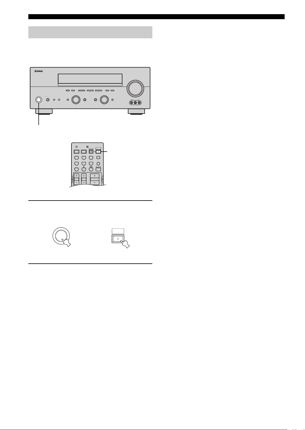
Turning on the power
When all connections are complete, turn on the power of
this unit.
(U.S.A. model)
VOLUME
l PRESET/TUNING h
INPUT MODETONE CONTROLSTRAIGHT
MEMORYFM/AMPRESET/TUNING
TUNING MODE
AUTO/MAN’L MONOMAN’L/AUTO FMLEVELNEXTEDIT
INPUT
MULTI CH
INPUT
VIDEO AUX
VIDEO L AUDIO R
A/B/C/D/E
PHONES
SPEAKERS
STANDBY
/ON
SILENT CINEMA
PROGRAM
BA
EFFECT
1
1
1 Press STANDBY/ON (SYSTEM POWER on
the remote control) to turn on the power of
this unit.
SYSTEM
STANDBY
/ON
Front panel
or
POWER
Remote control
2 Turn on the video monitor connected to this
unit.
22
Loading…
-
Страница 1
YAMAHA ELECTRONICS CORPORATION, USA 6660 ORANGETHO RPE AVE., BUEN A PARK, CALIF. 90620, U.S.A. YAMAHA CANADA MUSIC LTD. 135 MILNER AVE. , SCARBOROUGH, ONTAR IO M1S 3R1, CAN ADA YAMAHA ELECTRONIK EUROPA G.m.b.H. SIEMENSSTR. 22-34, 25462 RE LLINGEN BEI HAMBURG , F.R. OF GERMANY YAMAHA ELECTRONIQUE FRANCE S.A. RUE AMBROISE CROIZA T BP70 CROISSY-BEAUB […]
-
Страница 2
1 T o assure the finest performance, please read this manual carefully . Keep it in a safe place for future reference. 2 Install this sound system in a well ventilated, cool, dry , clean place — away fr om direct sunlight, heat sources, vibration, dust, moisture , and/or cold. Allow ventilation space of at least 30 cm on the top, 20 cm on the lef[…]
-
Страница 3
1 English PREP ARA TION INTRODUCTION BAS I C OPERA TION SOUND FIELD PROGRAM S AD V ANCED OPERA TION ADDITIONAL INFORMA TION FEATU RES …… ………… ………. ………… ……… ………… 2 GETTING STARTED … ………. ………… ………… ……. 3 Supplied accessories ………….. ……………. …………… ….. 3 Ins[…]
-
Страница 4
FEATURES 2 Built-in 6-channel power amplifier ◆ Minimum RMS output po wer (0.06% THD, 20 Hz – 20 kHz, 8 Ω ) Front: 90 W + 90 W Center: 90 W Surround: 90 W + 90 W Surround back: 90 W Sound field featur es ◆ Proprietary Y AMAHA technology for the creation of sound fields ◆ Dolby Digita l/Dolb y Digital EX decoder ◆ DTS/DTS-ES Matrix 6.1, […]
-
Страница 5
GETTING STARTED 3 English INTRODUCTION Please check t hat you recei ved all of the following parts. 1 Press the part and slide the battery compartment cover off. 2 Insert four supplied batteries (AAA, R03, UM-4) according to th e polarity markings (+ and –) on the inside of the battery compartment. 3 Slide the cover back unt il it sn aps into pla[…]
-
Страница 6
CONTROLS AND FUNCTIONS 4 1 ST AND BY/ON T urns on this unit or sets it to the standby mode. When you turn on this unit, you will hear a click a nd there will be a 4 to 5-second delay before this unit can reproduce sound. In standby mo de, this unit consumes a small amo unt of po wer in order to receive infrared-signa ls from the remote control. 2 R[…]
-
Страница 7
CONTROLS AND FUNCTIONS 5 English INTRODUCTION 0 PHONES (SILENT CINEMA) jack Outputs audio signals for pri v ate listening with headphones. When you connec t headphones, no sign als are output to the OUTPUT jacks or to the speakers. All Dolby Digital and DTS au dio signals are mix ed down to the left and right headphone channels. A SPEAKERS A/B T u […]
-
Страница 8
CONTROLS AND FUNCTIONS 6 This section describes the func tion of each control o n the remote control used to contro l this unit. T o operate other components, see “REMO TE CONTR OL FEA TURES” on page 54. 1 Infrared windo w Outputs infrared control signals. Aim thi s window at the component you want to operate. 2 CODE SET Use to set up manufactu[…]
-
Страница 9
CONTROLS AND FUNCTIONS 7 English INTRODUCTION H STRAIGHT (EFFECT) Switches the sound f ields of f or on. When STRAIGHT is selected, input signals (2-channel or multi-channel) are output directly from their respec tiv e speak ers without effect processing. I SET MENU (A/B/C/D/E) Acti vat es the SET MENU function . Selects preset station groups when […]
-
Страница 10
CONTROLS AND FUNCTIONS 8 1 Decoder indicator s When any of this unit’ s decode rs function, the respectiv e indicator lights up. 2 SILENT CINEMA indicator Lights up when headphones are connected and a sound field progr am is sele cted (see page 27). 3 NIGHT indica tor Lights up when you select night listening mode. 4 Input source indicators A cur[…]
-
Страница 11
CONTROLS AND FUNCTIONS 9 English INTRODUCTION K LFE indicator Lights up when the input signal contains the LFE signal. L Input chann el indicator s/speaker indicato rs Indicate the channe l components of the current digital input signal. Indicate the n umber of speak ers connected in SPEAKERS (page 24), or indicate the ch annel being adjusted in SP[…]
-
Страница 12
CONTROLS AND FUNCTIONS 10 1 DIGIT AL INPUT jacks See pages 15, 17 and 18 for details. 2 MUL T I CH INPUT jac ks See page 16 for connection information. 3 Video component ja cks See pages 15 and 17 for connection information. 4 A C OUTLET(S) Use to supply po wer to your other A/V components (see page 20). 5 DIGIT AL OUTPUT jack See page 18 for detai[…]
-
Страница 13
SPEAKER SE TUP 11 English PREP ARA TION The speaker layout belo w sho ws the standard ITU-R speaker setting. Y ou can us e it to enjo y CINEMA DSP and multi-channel audio sources. Front speaker s (FR and FL) The front speakers are used for the main source sound plus effect sounds. Place these speakers an equal distance from the ideal listening posi[…]
-
Страница 14
12 SPEAKER SETUP Be sure to connect the left ch annel (L), right channel (R), “+” (red) and “–” (black) prope rly . If the connections are faulty , no sound will be heard from the speakers, and if the polarity of the speaker connect ions is incorrect, the sound will be unnatural and lack bass. • If you will use 6 ohm speakers, be sure t[…]
-
Страница 15
13 English SPEAKER SE TUP PREP ARA TION ■ FRONT terminals Connect one or two speak er systems to these terminals. If you use only one speaker system , connect it to either the FR ONT A or B terminals. ■ CENTER terminals Connect a center speak er to these terminals. ■ SURROUND terminals Connect surround speak ers to these terminals. ■ SUB WO[…]
-
Страница 16
CONNECTIONS 14 Do not connect this unit or other components to the mains power until all connections between components are complete. ■ Cable indication s ■ Analog jac ks Y ou can input analog signals from audio components by connecting audio pin ca ble to the analog jacks on this unit. Connect red plugs to the right jacks and white plugs to th[…]
-
Страница 17
15 English CONNECTIONS PREP ARA TION ■ Connections f or D VD pla ybac k Connecting video components MONITOR OUT AUDIO VIDEO S VIDEO DVD VIDEO R L VIDEO COMPONENT VIDEO P R DVD MONITOR OUT P B Y DVD S VIDEO L R O DVD p l a ye r Video monitor Optical out V ideo out Audio out V i deo in 01EN_00_RXV550_EB.b ook Page 15 Thursday, Feb ruary 5, 2004 1:5[…]
-
Страница 18
16 CONNECTIONS ■ Connecting to the MUL TI CH INPUT jacks This unit is equipped with 6 additio nal input jacks (left and right FR ONT , CENTER, left and right SURROUND and SUB WOOFER) for discrete multi-channe l input from a multi-format player , external decoder , sound processor or pre- amplifier . Connect the output jacks on your multi-format p[…]
-
Страница 19
17 English CONNECTIONS PREP ARA TION ■ Connections f or other video components ■ VIDEO A UX jacks (on the fr ont panel) Use these jacks to connect an y video source, such as a game console or video camer a, to this uni t. AUD I O VIDEO S VIDEO DTV /CBL VIDEO R L OUT VCR IN COMPONENT VIDEO P R DTV /CBL P B Y DIGIT AL INPUT DTV/CBL CD COAXIAL OPT[…]
-
Страница 20
18 CONNECTIONS ■ Connections f or audio components Connecting audio components AUD I O R L IN ( PLA Y ) ( REC ) MD /CD-R CD DIGIT AL OUTPUT DIGIT AL INPUT OPTICAL MD/CD-R CD COAXIAL MD/CD-R L R L R L R O O C CD player MD recorder or tape dec k Coaxial out Audio out Audio in Audio out Optical in Optical ou t 01EN_00_RXV550_EB.b ook Page 18 Thursda[…]
-
Страница 21
19 English CONNECTIONS PREP ARA TION Both AM and FM indoor antennas are included with this unit. In genera l, these anten n as should provi de suf fici ent signal strength. Connect each antenna correctly to the designated terminals. ■ Connecting the AM loop anten na 1 Set up the AM loop ante nna , then connect it to the terminals on this unit. 2 […]
-
Страница 22
20 CONNECTIONS ■ Connecting the A C power cor d Plug the po wer cord into an A C wall outlet. ■ A C OUTLET(S) (SWITCHED) U.K. and Australia models .. ……….. ……….. …… 1 OUTLET K orea model …….. ……….. ……….. ………… ……….. ………. None Other models ………….. ……….. ……….. ……….. …2 […]
-
Страница 23
21 English CONNECTIONS PREP ARA TION ■ IMPED ANCE SELECTOR s witch Do not change the setting of the IMPED ANCE SELECT OR switch when the unit po wer is switched on, as doing so may damage the unit. If this unit fails to turn on when ST ANDBY/ON is pressed on either the front panel or remote control, the IMPED ANCE SELECT OR switch may not be full[…]
-
Страница 24
22 CONNECTIONS When all connections are complete, turn on the power of this unit. 1 Press ST ANDBY/ON (SYSTEM PO WER on the remote control) to turn on the power of this unit. 2 T urn on the video monitor connected to this unit. T urning on the power AUTO/MAN’L MONO MAN’L/AUTO FM LEVEL NEXT EDIT EFFECT MEMORY FM/AM PRESET/TUNING A/B/C/D/E […]
-
Страница 25
BASIC SETUP 23 English PREP ARA TION The basic setup feat ure is a useful w ay to set up your system quickly and with minimal ef fort. y • If you wish to conf igure the un it manually using more precise adjustments, use the detailed parameter s in SOUND MENU (page 50) instead of using BASIC SETUP. • Altering any parameters in BASIC SETUP will r[…]
-
Страница 26
24 BASIC SETUP 7 Press d to display the SPEAKERS parameter . 8 Press j / i to select the number of speakers you connected. SPEAKERS 6spk 9 Press d to display SET/CANCEL. 10 Press j / i to select the desired se tting. >SET CANCEL SET T o apply the settings you chose in steps 4 through 8. CANCEL T o cancel the se tup without making any changes. 11[…]
-
Страница 27
25 English BASIC SETUP PREP ARA TION ■ T o bal ance the spea ker le vels Perform the follo wing steps after step 13 (see page 24). The unit outputs the test tone from the selected speaker and the left front (or left surround) speaker in turn. The indicator of the speaker curre ntly outputting the test tone flashes in the front panel display . 1 P[…]
-
Страница 28
PLAYBACK 26 1 Press ST ANDBY/ON (SYSTEM PO WER on the remote control) to turn on the power . 2 T urn on the video monitor connected to this unit. 3 Press SPEAKERS A or B on the front panel. Each press turns the respecti ve speak ers on or of f. 4 Select the input source. Use INPUT (or press one of the input selector b uttons on the remote control) […]
-
Страница 29
27 English PLAYBACK BAS I C OPERA TION 7 Select a sound fiel d program if desired. Rotate PR OGRAM (or press AMP on the remote control to select the AMP mode, then press one of the sound field program b uttons repeatedly) to select a sound field p rogram. (See page 43 for details about sound field programs.) T o listen wit h headphones ( SILENT CIN[…]
-
Страница 30
28 PLAYBACK ■ Selecting MUL TI CH INPUT Press MUL TI CH INPUT so that “MUL TI CH INPUT” appears in the front panel display and video monitor . MULTI CH INPUT When “MUL TI CH INPUT” is shown in the front panel display , no other source can be played. T o select another input source with INPUT (or one of the input selector b uttons), pres s[…]
-
Страница 31
29 English PLAYBACK BAS I C OPERA TION ■ Remote contr ol operation Press AMP to select the AMP mode, then press one of the sound field program buttons repeatedly to select the desired program. The name of the selected program appears in the front panel display . y Feel free to choose a sound f ield program based on your listening preference, and […]
-
Страница 32
30 PLAYBACK • Some 6.1-channel compatible discs do not ha ve a signal (flag) which this unit can automatically detect. Whe n playing these kinds of discs with 6.1-channe l, select a decoder manually (PLIIx Music, EX/ ES or EX). • 6.1-channel playback is not possibl e e ven if EX/ES is pressed in the following cases: – When “SURR LR” (see […]
-
Страница 33
31 English PLAYBACK BAS I C OPERA TION ■ Listening to high fidelity stereo sound (Direct Stereo) Direct Stereo allo ws you to b ypass this unit’ s decoders and DSP processors to enjoy pure high fidelity sound from 2- channel PCM and analog sources. Rotate PROGRAM (or pre ss AMP to select the AMP mode, then press ST EREO repeatedly) to select ?[…]
-
Страница 34
32 PLAYBACK ■ Down mixing to 2 c hannels Y ou can enjoy 2-channel stereo playback ev en from multi- channel sources. Rotate PROGRAM (or press STEREO on the remote control) to select 2ch Stereo. 2ch Stereo y Y ou can use a subwoofer with this program when SWFR or BO TH is selected in “BASS OUT”. ■ Listening to unpr oces sed input signals In […]
-
Страница 35
33 English PLAYBACK BAS I C OPERA TION • When you play DTS-encoded CD/LDs with the input mode set to A UT O: – This unit automatically switches to the DTS decoding mode. The unit remains in DTS mode (and the t indicator may flash) for up to 30 seconds after playb ack of the DTS source is complete. T o manually release the D TS mode, press INPUT[…]
-
Страница 36
TUNING 34 There are 2 tuning methods ; automatic and manual. Automatic tuning is ef fectiv e when station signals are strong and there is no interference. ■ A utomatic tuni ng 1 Rotate INPUT to select TUNER as the input sour ce. 2 Press FM/AM to select the reception band. “FM” or “AM” appears in the front panel display . 3 Press TUNING MO[…]
-
Страница 37
35 English TUNING BAS I C OPERA TION ■ Manual tuning If the signal from the station you want to select is weak, tune into it manually . Manuall y tuning into an FM station will automatical ly switch the tuner to monaur al reception to increase the signal qua lity . 1 Select TUNER and the reception band follo wing steps 1 and 2 as described in “[…]
-
Страница 38
36 TUNING 3 Press and hold MEMOR Y (MAN’L/A UT O FM) for more than 3 seconds. The preset number , the MEMOR Y and A UT O indicators flash. After a bout 5 seconds, automatic presetting starts from the frequency currently displayed and proceeds to ward the higher frequencies. When automatic pre set tuning is comple ted, the front panel display sho […]
-
Страница 39
37 English TUNING BAS I C OPERA TION 4 Press PRESET/TUNING l / h to select a preset station number (1 through
 while the MEMOR Y indicator is flashing. Press h to select a higher preset station number . Press l to select a lower preset station number . 5 Press MEMOR Y (MAN’L/A UT O FM) on the front panel while the MEMOR Y indicator is flashing.[…]
 -
Страница 40
38 TUNING Y ou can exchange t he assignmen t of two preset stations with each other . The example belo w describes the procedure for exchanging preset station “E1” with “A5”. 1 Select preset station “E1” using A/B/C/D/E and PRESET/TUNING l / h . See “Selec ting preset sta tions”. 2 Press and hold PRESET/TUNING (EDIT) for more than 3[…]
-
Страница 41
39 English TUNING BAS I C OPERA TION RDS (Radio Data System) is a data transmission system used by FM stations in many countries. The RDS function is carried out among the network stations. This unit can receiv e v arious RDS data such as PS (Program Service na me), PTY (Program T ype), R T (Radio T ext), CT (Clock T ime ), EON (Enhanced Other Netw[…]
-
Страница 42
40 TUNING If you select the desired program type, this unit automaticall y searches all preset RDS stations that are broadcasting a program of the required type. y When performing this operation with the remote control, first press TUNER to set the remote to tuner mode. 1 Press PTY SEEK MODE to se t this unit in the PTY SEEK mode. The program type […]
-
Страница 43
41 English TUNING BAS I C OPERA TION This function uses the EON data service on the RDS station network. If you select the desired program type (NEWS, INFO, AFF AIRS or SPOR T), this unit automatical ly searches for all preset RD S stations that are scheduled to broadcast the se lected type of program and switches from the station curr ently being […]
-
Страница 44
RECORDING 42 Recording adjustments a nd other operations are performed from the recording components. Refer to the operating instructions for those components. 1 T urn on the power of this un it and al l connected c omponents. 2 Select the source component y ou want to record fr om. 3 Start playbac k (or select a broadcast station) on the source co[…]
-
Страница 45
SOUND FIELD PROGRAM DESCRIPTIONS 43 English SOUND FIELD PROGRAM S This unit is equipped with a variety of precise digital de coders that allo w you to enjo y multichannel playback from almost any sound sour ce (stereo or mu ltichannel). This unit is also equipped with a Y AMAHA digital sound f ield processing (DSP) chip containing se veral sound f […]
-
Страница 46
44 SOUND FIELD PROGRAM DESCRIPTIONS * Y ou can select either Pro Logic IIx or Pro Logic II processing using the PLII/PLIIx parameter on page 61. DOLBY DIGITAL : SUR. STANDARD Standard 5. 1-channel p rocessing f or Dolby Digit al sources. MUL TI DOLBY DIGITAL : SUR. ENHANCED CINEMA DSP enh anced proc essing for Do lby Digita l sources. DOLBY D EX : […]
-
Страница 47
45 English SOUND FIELD PROGRAM DESCRIPTIONS SOUND FIELD PROGRAM S Y ou can select from the follo wing sound fields when playi ng music sources, like CD, FM /AM broadcasting, tapes, etc. * Y o u can select either Pr o Logic IIx or Pro Logic II processin g using the PLII /PLIIx parameter on page 61. For music sources Program Features Sources CONCERT […]
-
Страница 48
ADVANCED OPERATIONS 46 Use this feature to automa tically set this unit in the standby mode after a certain amount of time. The sleep timer is useful when you are goi ng to sleep while this unit is playing or recording a s ource. The sleep timer also automatically turns of f an y e xternal components connected to the A C OUTLET(S). ■ Setting the […]
-
Страница 49
47 English ADVANCED OPERATIONS AD V ANCED OPERA TION Y ou can adjust the output level of each speak er while listening to a music source. This is also possible when playing sources through th e MUL TI CH INPUT jacks. Please note that this operation will o verri de the lev el adjustments made in “BASIC SETUP” (page 23), “SP LEVEL” (page 51) […]
-
Страница 50
SET MENU 48 Y ou can use the follo wing parameters in SET MENU to adjust a v ariety of system settings and customize the way this unit operates. Change the ini tial settings (indicated in bold under ea ch parameter) to reflect the needs of your listening en vironment. ■ BA SIC SETUP Use to quickly setup basic syst em parameters (see page 23). ■[…]
-
Страница 51
49 English SET MENU AD V ANCED OPERA TION Use the remote control to acce ss and adjust each parameter . y Y ou can change SET MENU para meters while the unit is reproducing sound . Y ou cannot change some SET MENU parameters while the unit is in either cinema or music ni ght listening mode. 1 Press AMP. 2 Press SET MENU. “B ASIC SETUP” appears […]
-
Страница 52
50 SET MENU Use to manually adjust any sp ea ker setting or compensate for video signal processin g delays when using LCD monitors or projectors. Most of the SOUND MENU parameters are set aut oma tically when you perform “B ASIC SETUP” (see page 23). ■ Speaker set A)SPEAKER SET Use to manually adjust any speaker setting. y If you are not sati[…]
-
Страница 53
51 English SET MENU AD V ANCED OPERA TION ■ Speaker le vel B )SP LEVEL Use these se ttings to manuall y balance the speaker le vels between the front left o r surr ound left speakers and each speaker selected in SPEAKER SET (page 50). Choices: –10.0 dB to +10.0 dB • FR adjusts the balance of the front left and front right speakers. • C adju[…]
-
Страница 54
52 SET MENU ■ Aud i o s e t G)AUDIO SET Use to customize this units o v erall audio settings. A udio m ute A.MUTE Use to adjust how much the mute function reduces the output volume. Choices: MUTE , –20 dB • Select MUTE to com pletely halt all output of sound. • Select –20 dB to reduce the current v olume b y 20 dB. A udio dela y A.DELAY U[…]
-
Страница 55
53 English SET MENU AD V ANCED OPERA TION Use to adjust the optional system param eters. ■ Display set A)DISPLAY SET Dimmer DIMMER Use to adjust the brightness of the front panel display . Choices: –4 to 0 Video con ver sion V CONV. Use this feature to turn on/off con version of composite (VIDEO) signals to S-V ideo si gnals. This allo ws you t[…]
-
Страница 56
REMOTE CONTROL FEATURES 54 In addition to controlling this unit, th e remote control can also operate other A/V compone nts made by Y AMAHA and other manufacturers. T o contro l other components, you must set up remote c ontrol with the appropriate manufacturer codes. ■ Controlling this unit The shaded a reas belo w can be used to control this un[…]
-
Страница 57
55 English REMOTE CONTROL FEATURES AD V ANCED OPERA TION Y ou can control other co mponents b y setting the appropriate manufacturer code s. Codes can be set up for each input area. F or a comp lete list of av ailable manufacturer codes, refer to “LIST OF MANUF A CTURER CODES” at the end of this manual. The follow ing table sho ws the factory p[…]
-
Страница 58
56 REMOTE CONTROL FEATURES Once you set the appropriate manufacturer codes, you can use this remote to control your other components. Note that some b uttons ma y not correctly operate the sele cted component. Use the input select or b uttons to select the component you want to operate. The remote control automatically switches to the appropriate c[…]
-
Страница 59
57 English REMOTE CONTROL FEATURES AD V ANCED OPERA TION ■ Clearing a setup man ufacturer code f or component contr ol 1 Press an input selector button or / to select the component control f or which y ou want to clear the manufacturer code. 2 Press CODE SET using a ballpoint pen or similar object. The TRANSMIT indicator on the remot e control fl[…]
-
Страница 60
EDITING SOUND FIELD PARAMETERS 58 What really crea tes the rich, full tones of a li ve instrument are the multi ple reflections from the walls of the room. I n addition to making the sound “live”, these reflections enable us to tell where the player is situa ted, and the size and shape of the room in which we are sitting. ■ Elements of a soun[…]
-
Страница 61
59 English EDITING SOUND FIELD PARAMETERS ADDITIONAL INFORMA TION 5 Repeat st eps 2 th roug h 4 as n ecessary t o change other pr ogram parameter s. Y ou cannot change parameter va lues when “MEMOR Y GU ARD” is set to ON. If you want to cha nge the parameter v alues, set “MEM OR Y GU ARD” t o OFF (se e page 53) . ■ Resetting paramet ers t[…]
-
Страница 62
SOUND FIELD PARAMETER DESCRIPTIONS 60 Y ou can adjust the values of certain digital sound field para meters so the sound fields are recreated accurately in your listening room. Not all of the follo wing parameters are found in e v ery program. ■ DSP LEVEL Function: This parameter adjusts the le vel of al l the DSP ef fect sounds within a narro w […]
-
Страница 63
61 English SOUND FIELD PARAMETER DESCRIPTIONS ADDITIONAL INFORMA TION For PR O LOGIC IIx Music and PR O LOGIC II Music ■ P ANORAMA Function: Extends the front stereo image to incl ude the surround speakers for wraparound ef fect. Choices: OFF/O N, initial setting is OFF. ■ DIMENSION Function: Gradually adjusts the sound field either to wards th[…]
-
Страница 64
TROUBLESHOOTING 62 Refer to the chart belo w when this unit does not function p roperl y . If the problem you are e xperiencing is not listed belo w or if the instruc tion belo w does not help, set this unit to the standby mode, disconnect th e po wer cord, and contact the nearest authorized Y AMAHA dealer or service center . ■ General TROUBLESHO[…]
-
Страница 65
63 English TROUBLESHOOTING ADDITIONAL INFORMA TION Prob lem Cause Remedy Refer to page The sound su ddenly goes off. The protect ion circuitr y has been activated because of a short cir cuit, etc. Check that the impedan ce selec tor setting is correct . 21 Check that the speaker wi res are not touching each other and the n turn this uni t back on. […]
-
Страница 66
64 TROUBLESHOOTING Problem Cause Remedy Refer to page Dolby Digital or DTS sources cannot be played. (Dolby Digital or DTS indicator in the front panel display does not light up.) The connecte d componen t is not se t to output Dolby Dig ital or DTS digital signals. Make an appropriat e setting following the ope rations instruct ions for your compo[…]
-
Страница 67
65 English TROUBLESHOOTING ADDITIONAL INFORMA TION ■ T uner ■ Remote contr ol Problem Cause Remedy Refer to page FM FM stereo r eception i s noisy . The charact eristics of FM stereo broadcas ts may cause this problem when the transmitt er is too far a way or the antenna input is poor . Check the a ntenna co nnection s. T ry using a hig h-quali[…]
-
Страница 68
RESETTING THE FACTORY PRE SETS 66 If you want to reset all of your unit’ s parameters for any reason, do the follo wing. This procedure completely reset s ALL parameters, including th e SET MENU, lev el, assign and tuner presets. Be sure this unit is in standb y mode. 1 Hold down STRAIGHT (EFFE CT) on the fr ont panel and press ST ANDBY/ON. “F […]
-
Страница 69
GLOSSARY 67 English ADDITIONAL INFORMA TION ■ Dolby Digital Dolby Digital is a digital surround sound system that giv es you completely independent mu lti-channel audio. W ith 3 front channels (left, center , and right), and 2 surround stereo channels, Dolb y Digita l pro vides 5 full-rang e audio channels. W ith an additional channel especially […]
-
Страница 70
68 GLOSSARY ■ CINEMA DSP Since the Dolby Surround and DTS systems were originally designed for use in movie theaters, their effect is best felt in a theater ha vi ng many speak ers and designed for acoustic effects. Since home conditions , such as room size, wall material, number of speak ers, and so on, can diff er so widely , it’ s inevitable[…]
-
Страница 71
69 English GLOSSARY ADDITIONAL INFORMA TION ■ Component video signal W ith the component video signal system, the video signal is separated into the Y signa l for the luminance and the P B and P R signals for the chromi nance. Co lor can be reproduced more faithfully with this system because each of these signals is independ ent. The component si[…]
-
Страница 72
SPECIFICATIONS 70 A UDIO SECTION • Mi nimum RMS Out put Power for Front, Cent er , Surround, Surround ba ck 20 Hz to 20 kHz, 0.0 6% THD, 8 Ω … ………………….. …………. 90 W • Maximum Power (EIAJ) [China, Korea and Gene ral model s] 1 kHz, 10% THD, 8 Ω …………………. ……………… …………….. 130 W • D yna[…]
-
Страница 73
i LIST OF MANUF A CTURER CODES LISTE DES CODES DE F ABRICANT LISTE DER H ERSTELLERCODES LIST A Ö VER TILL VERKARK ODER LIST A DEI CODICI DEI F ABBRICANTI LIST A DE CÓDIGOS DE F ABRICANTES LIJST MET F ABRIKANTENCODES СПИСОК К ОДОВ ПР ОИЗВОДИТЕЛЕЙ TV ADMIRAL 0411, 0451, 0911, 1021, 1081 AIKO 0891 AKAI 0061, 0101, 0231, 1191[…]
-
Страница 74
ii KOR TING 0431, 1011, 1021, 1081, 1541 KTV 0601, 1171 LENOIR 0601, 1511 LEYEO 1181 LG (GOLDST AR) 05 91, 0601, 0761, 0791, 1371, 1491, 1511, 1561, 1621, 1641 LIFETEC 259 1, 2601, 2611, 2621, 2641, 2651, 2661, 2671, 2681, 2691, 2711, 2761, 2771, 2781 LOEWE OPT A 0121, 0131, 0581, 0611, 1081 LOGIC 1691, 2281 LOGIK 0551, 1681, 2281 LOWEWE 0831 LUMA […]
-
Страница 75
iii THOMSON 0331 , 0481, 0531, 0571, 0631, 0651, 0731, 0901, 1241, 1571, 1591, 1791, 1811, 1821, 1891, 1941, 2531 THORN 0741, 0861, 2091, 2251, 2271, 2281 THORN-FERGUSON 0281, 0371, 0551, 0651, 0781, 0861, 0881, 1131, 1181, 1361, 1461, 1971, 1991, 2281 TMK 0141, 0791 , 1471 TOSHIB A 0141, 0381, 048 1, 1221, 1271, 1701, 1741, 1851, 2151, 2801, 2811 […]
-
Страница 76
iv FR ONTECH 0112 FUNAI 0432 GBC 0002 GEC (UK) 002 2, 0052 GELOSO 0002 GENERAL TECHNIC 1172 GOODMANS 000 2, 0072, 0282, 0432, 0502 GOODMANS (UK) 0002 GRAETZ 0022, 004 2 GRANAD A 0052, 0132, 0532, 0572 GRANAD A (UK) 00 52, 0092, 0462, 0602, 0812, 0822 GR UNDIG 0052, 0062, 0092, 0232, 0252, 0262, 0752, 0802 HANSEA TIC 0052, 0812 HARMAN/KARDON 0122, 0[…]
-
Страница 77
v GENEXXA 0525, 0825, 0855, 0875, 0995, 1265, 1285, 1345, 1355, 1485, 1575, 1675, 1715, 1825 GR UNDIG 0175 HARMAN KARDON 0325, 0495, 0565, 1135, 1145, 1155 HIT ACHI 0065 , 0585, 0685, 0945, 1005, 1015, 1225, 1545 INNO V A TION 1995 , 2005, 2015 ITT -NOKIA 0185 JVC (VICTOR) 0385, 03 95, 0455, 0575, 0585 KARCHER 0485 KENWOOD 0025, 0055, 014 5, 0215, […]
-
Страница 78
YAMAHA ELECTRONICS CORPORATION, USA 6660 ORANGETHO RPE AVE., BUEN A PARK, CALIF. 90620, U.S.A. YAMAHA CANADA MUSIC LTD. 135 MILNER AVE. , SCARBOROUGH, ONTAR IO M1S 3R1, CAN ADA YAMAHA ELECTRONIK EUROPA G.m.b.H. SIEMENSSTR. 22-34, 25462 RE LLINGEN BEI HAMBURG , F.R. OF GERMANY YAMAHA ELECTRONIQUE FRANCE S.A. RUE AMBROISE CROIZA T BP70 CROISSY-BEAUB […]
 while the MEMOR Y indicator is flashing. Press h to select a higher preset station number . Press l to select a lower preset station number . 5 Press MEMOR Y (MAN’L/A UT O FM) on the front panel while the MEMOR Y indicator is flashing.[…]