
| Название | Русский | English |
|---|---|---|
| DTP4K2SP/DTP4K2STD Pads Set Accessories List | — |
[148KB] |
| DTP4KSP/DTP4KSTD Pads Set Accessories List | — |
[233KB] |
| DTXPRESS II Owner’s Manual (Basic Guide) | — |
[4.6MB] |
| DTXPRESS II Owner’s Manual (Basic Guide) (Text Version) | — |
[131KB] |
| DTXPRESS II Owner’s Manual (Reference Guide) | — |
[2.3MB] |
| DTXPRESS III Owner’s Manual (Basic Guide) | — |
[4.6MB] |
| DTXPRESS III Owner’s Manual (Basic Guide) (Text Version) | — |
[137KB] |
| DTXPRESS III Owner’s Manual (Reference Guide) | — |
[1.6MB] |
| DTXPRESS IV Owner’s Manual | — |
[1.4MB] |
| DTXPRESS IV Owner’s Manual |
[4.4MB] |
[1.4MB] |
| DTXPRESS IV Special Set Assembly Manual | — |
[838KB] |
| DTXPRESS IV Standard Set Assembly Manual | — |
[748KB] |
| DTXPRESS Owner’s Manual | — |
[2.9MB] |
| DTXPRESS Owner’s Manual (Text Version) | — |
[130KB] |
| DTXPRESS Reference Guide | — |
[1.9MB] |
DRUM TRIGGER MODULE
DRUM TRIGGER MODULE
English
Français
Deutsch
Owner’s Manual / Reference Guide
Mode d’emploi / Guide de référence
Bedienungsanleitung / Referenzhandbuch
Español
Italiano
Manual de instrucciones / Guía de referencia
Manuale dell’utente / Guide di riferimento

CONTENTS
How to use the Manual
The DTXPRESS II Owner’s Manual is divided into the following two books.
● Basic Guide
Please read this book before using the
DTXPRESS II.
This book contains cautions that must be followed for
safe and proper use of the DTXPRESS II.
Also, control and function names, connecting the pads
and how to play the DTXPRESS II, how to record
and playback songs, how to create original drum kits
are all described in this book.
At the rear of this book you will find an appendix section with specifications and error messages.
● Reference Guide (this book)
This book describes in detail each of the DTXPRESS
II’s functions.
At the rear of this book you will find an appendix section with drum voice, song, MIDI data format, etc.
About the descriptions
This manual describes buttons and explanations using the
following rules.
• [DRUMKIT], [>/■], etc.
The button on the front panel is indicated with
[ ]. (brackets).
• [SHIFT]+[>/■], etc.
Means hold the [SHIFT] button and press the [>/■]
button.
•[PAGEs]/[PAGEt], etc.
Means use the [PAGEs] button or [PAGEt] button.
•“Complete!”, etc.
Words inside “ ” indicate the message shown on the
display.
• m P. 10, etc.
Indicates the reference page where further information can be found.
NOTE
The illustrations and LCD screens as shown in this
owner’s manual are for instructional purposes only,
and may appear somewhat different from those on
your instrument.
DTXPRESS II Internal Makeup…………. 4
Drum Kit Play Mode ………………………… 6
1. Drum Kit & Song ……………………………………6
2. Trigger Setup & Tempo…………………………… 6
3. Song & Mute …………………………………………. 7
Groove Check Function…………………………….. 7
About the Song ………………………………. 8
Song Playback………………………………………….. 8
Song Recording ……………………………………… 10
Trigger Setup Edit Mode ………………… 11
1. INPUT Parameters ………………………………..12
1-1. Pad Type ………………………………………………. 12
1-2. Gain, Minimum Velocity ………………………….. 12
1-3. Velocity Curve ……………………………………….. 13
1-4. Self Rejection, Rejection ………………………… 13
1-5. Specific Rejection ………………………………….. 13
1-6. Trigger Setup Copy ………………………………… 13
2. COMMON PARAMETERS ……………………… 14
2-1. Increment/Decrement …………………………….. 14
2-2. Input Exchange ……………………………………… 14
2-3. Trigger Setup Name ……………………………….. 14
Drum Kit Voice Edit Mode ………………. 15
1. Voice Parameters ………………………………….16
1-1. Voice ……………………………………………………. 17
1-2. Volume, Pan………………………………………….. 17
1-3. Tuning ………………………………………………….. 17
1-4. Layer Balance ……………………………………….. 18
1-5. Decay, Cutoff Frequency ………………………… 18
1-6. Note Number ………………………………………… 18
1-7. Channel, Gate Time……………………………….. 18
2. Input Common Parameters ………………….. 19
2-1. Cross Fade …………………………………………… 19
2-2. Reverb Send …………………………………………. 19
2-3. Alternate Group, Key Assign Mode ………….. 19
2-4. Hold Mode ……………………………………………. 20
2-5. Key Off Enable………………………………………. 20
2-6. Function ………………………………………………..20
2-7. Pad Song ………………………………………………20
2-8. Rim To Pad …………………………………………… 21
2

CONTENTS
3. Reverb Parameter………………………………… 21
3-1. Reverb Type, Time …………………………………. 21
3-2. Reverb Master Return ……………………………. 21
4. Setup ………………………………………………….. 22
4-1. Program Change, Bank Select ………………… 22
4-2. Volume, Pan ………………………………………….. 22
4-3. Drum Kit Voice Copy………………………………. 22
5. Drum Kit Common Parameters ……………..23
5-1. Volume …………………………………………………. 23
5-2. Drum Reverb Send …………………………………23
5-3. Hi-hat Sensitivity ……………………………………. 23
5-4. Song Select ………………………………………….. 23
5-5. Drum Kit Name ……………………………………… 23
Song Edit Mode …………………………….. 24
1. Tempo, Repeat Playback …………………………… 24
2. Program Change, Bank Select …………………… 24
3. Volume, Pan …………………………………………….. 25
4. Song Copy ………………………………………………. 25
5. Quantize …………………………………………………. 25
6. Clear Track ……………………………………………….26
7. Merge Track …………………………………………….. 26
8. Clear Song ………………………………………………. 26
9. Song Name ……………………………………………… 26
Utility Mode …………………………………… 27
1. TG (Tone Generator) Group …………………..28
1-1. Equalizer (EQ) ………………………………………. 28
1-2. Mute…………………………………………………….. 28
1-3. Tuning …………………………………………………..28
1-4. Volume …………………………………………………. 28
1-5. Reverb Bypass ……………………………………… 28
2. SYSTEM Group……………………………………. 29
2-1. Learn Mode ………………………………………….. 29
2-2. Trigger Bypass ……………………………………….29
2-3. Volume Mode ………………………………………… 29
2-4. Jump to Recent Page …………………………….. 29
2-5. Hi-Hat Offset …………………………………………. 30
2-6. Factory Set …………………………………………… 30
3. MIDI Group ………………………………………….. 30
3-1. Bulk dump…………………………………………….. 30
3-2. Channel 10 Program Change/Channel Event
Receive ……………………………………………….. 31
3-3. Receive Program Change/System
Exclusive Messages………………………………. 31
3-4. Program Change Table …………………………… 32
3-5. MIDI Mode ……………………………………………. 32
3-6. Device Number, Local Control …………………. 32
3-7. MIDI Merge ……………………………………………32
3-8. Dump Interval ……………………………………….. 33
3-9. Send Hi-Hat Control ………………………………. 33
3-10. Host Thru Port …………………………………….. 33
4. Sequencer Group ………………………………… 33
4-1. Click Voice ……………………………………………. 33
4-2. Click Tune …………………………………………….. 34
4-3. Click Note Number ………………………………… 34
4-4. MIDI Control …………………………………………. 34
4-5. Count Switch ………………………………………… 34
4-6. Sync Mode……………………………………………. 34
4-7. Use Tempo……………………………………………. 35
4-8. Click Mode …………………………………………….35
5. MAP (Drum Map) Group……………………….. 35
5-1. Voice …………………………………………………….35
5-2. Volume, Pan ………………………………………….. 36
5-3. Tuning …………………………………………………..36
5-4. Layer Balance ……………………………………….. 36
5-5. Decay, Cutoff Frequency ………………………… 36
5-6. Reverb Send …………………………………………. 36
5-7. Alternate Group, Key Assign Mode ………….. 37
5-8. Key Off Enable………………………………………. 37
5-9. Map Copy …………………………………………….. 37
Drum Voice List …………………………….. 38
GM Keyboard Voice List…………………. 42
Preset Drum Kit List………………………. 42
Preset Song List ……………………………. 49
Trigger Setup List………………………….. 49
MIDI Data Format…………………………… 50
MIDI Implementation Chart…………….. 52
Blank Chart …………………………………… 53
3
DTXPRESS
II
Internal Makeup
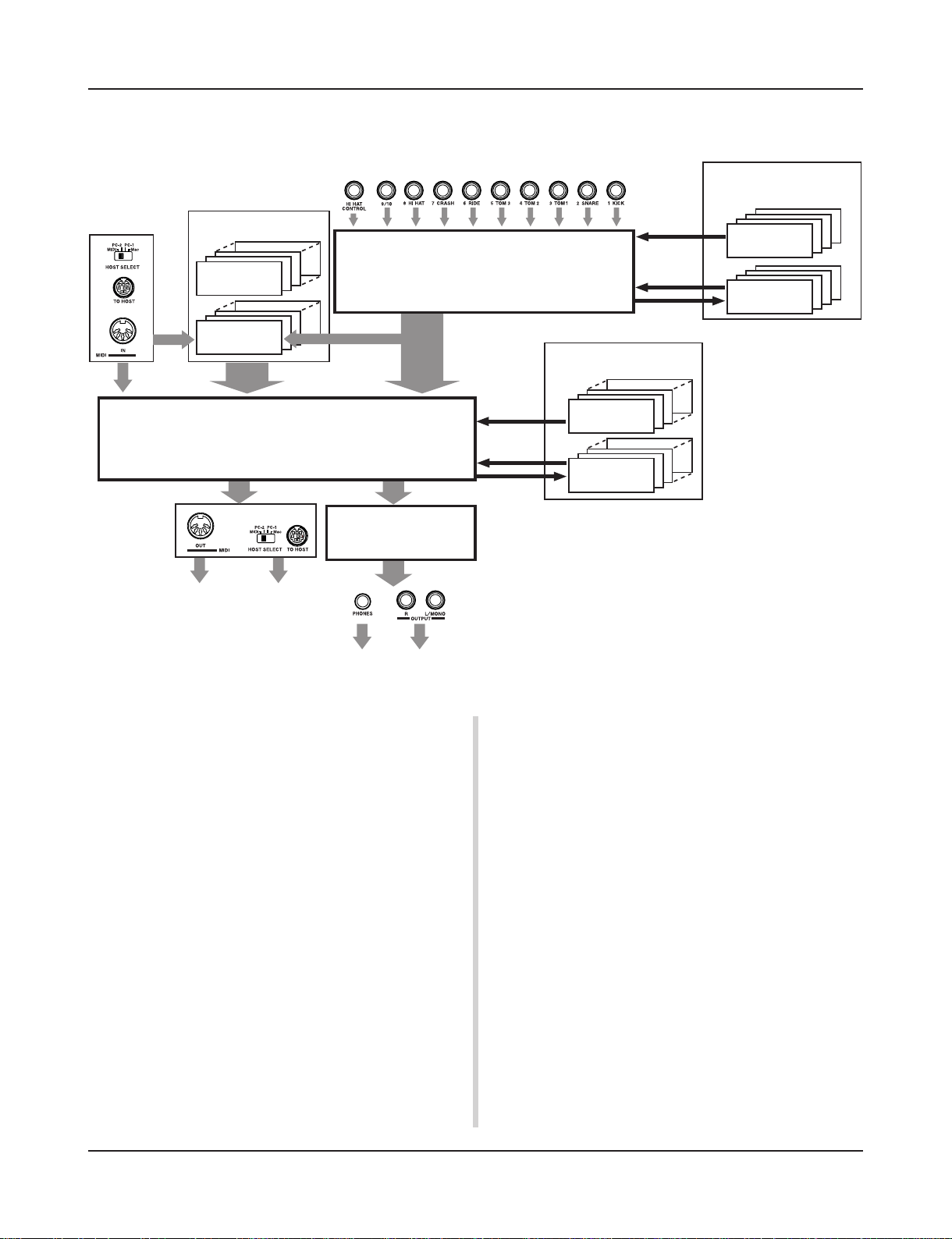
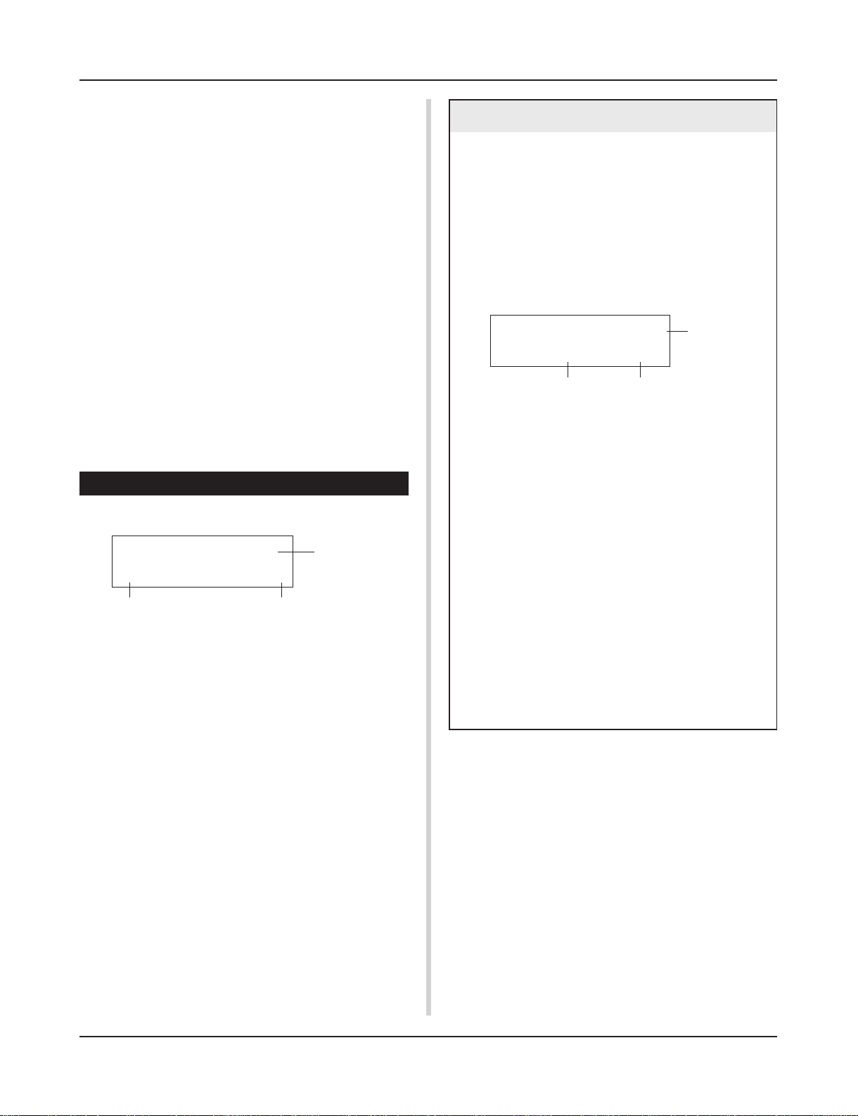
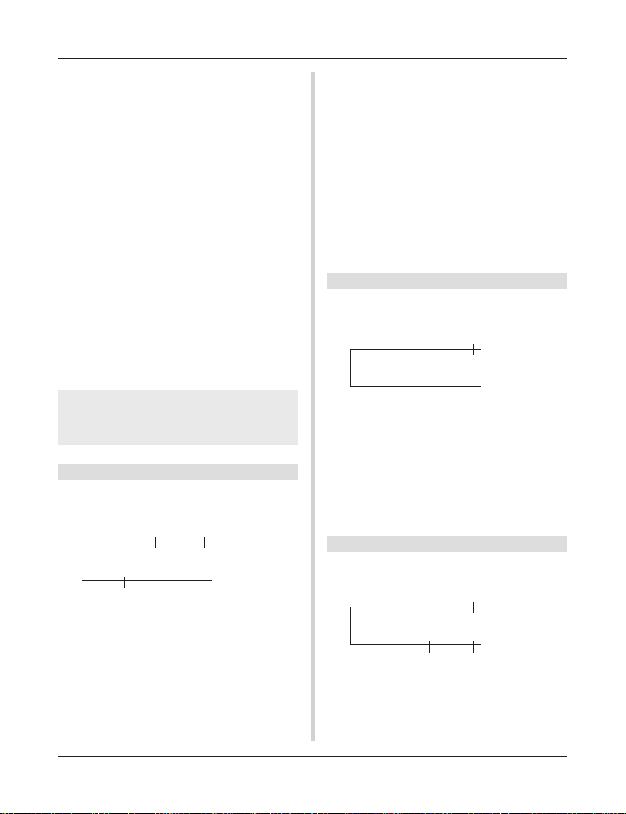
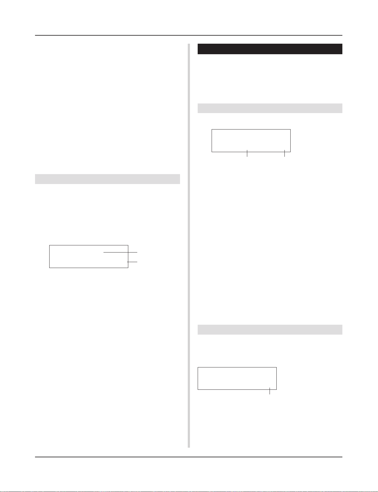
■ The DTXPRESS II’s Internal Signal Flow
Sequencer data
from a computer
or an external
MIDI device.
Song Data
Preset
No. 1-95
User
No. 96-127
Record
Drum Kit Data Buffer
Transmits key on/off, program
change, note number, etc.
MIDI data to a computer or an
external MIDI device.
Playback
Input for Trigger Signals produced when the pad is struck
Trigger Setup Data Buffer
Record
Tone Generator
Audio Signal Output
Copy
Copy
Store
The Tone Generator is sounded according to the Drum Maps
for each of the Drum Kits
• Each Preset Drum Kit has its own Drum Map
• User Drum Kits No. 49-80 use a common (one) Drum Map.
Drum Kit Data
Preset
No. 1-48
User
No. 49-80
Trigger Setup Data
Preset
No. 1-5
User
No. 6-9
● Pad Data Signal Flow
In order for the DTXPRESS II to effectively manage trigger signals transmitted from the pads connected to the Trigger Input Jacks
(1 KICK, 2 SNARE, … 9/10) and the HI HAT CONTROL jack,
trigger signals are adjusted to a suitable signal in the Trigger Setup
Buffer using the Trigger Setup.
Signals transmitted from the Trigger Setup Buffer will enter the
Drum Kit Buffer.
In the Drum Kit Buffer, the Drum Kit is set as to what voices will
be used and how voices will be delivered for each of the Trigger
Input Sources. The Tone Generator’s Voices will be produced
according to these settings and its audio signal will be transmitted
to the OUTPUT jacks and PHONES jack.
● Trigger Setup Data
This mode is used for adjusting the trigger input, from pads and
trigger sensors connected to the Trigger Input Jacks, to a suitable
signal the sensitivity and velocity curve settings. (The signals characteristics will change according to the strength of the hit.) Also,
cross-talk and double-trigger can be effectively eliminated with
the settings available here.
4
Along with 5 preset trigger setups (No. 1-5), there are another 4
user trigger setups (No. 6-9) available for storing original setups.
After selecting a trigger setup for use, the data will be copied to
the Trigger Setup Data Buffer where the copied data will be used
in performance. (Refer to the illustration above.)
Setup data can be freely changed in the Trigger Setup Edit mode
and saved, if necessary, to the User Trigger Setup’s memory (No.
6-9).
● Drum Kit Data
This mode is used for setting drum kit voices, for example, assign
a voice to each pad (trigger input source) used in the drum kit and
perform settings such as selecting the voice, tuning, reverb level,
etc.
The DTXPRESS II has 48 preset (No. 1-48) drum kits and another
32 user (No. 49-80) drum kits that are used for saving original
drum kits created by the user.
As in the Trigger Setup, the selected drum kit’s data will be copied
to the Drum Kit Data Buffer where the copied data will be used in
performance. (Refer to the illustration above.) This Drum Kit data
can be freely changed in the Drum Kit Voice Edit mode and saved,
if necessary, to the User Drum Kit’s memory (No. 49-80).
DTXPRESS II Internal Makeup
● Tone Generator
The DTXPRESS II’s tone generator contains a total of 928 drum
and percussion voices.
Preset Drum Kits use an exclusive Drum Kit Map for each kit in
which voices for the kit are assigned to individual MIDI note numbers.
The User Drum Kit uses one drum map (User Drum Map) that is
common for all drum kit numbers 49-80. The Utility mode’s [5.
Map (Drum Map)] group can be used to assign voices to each
MIDI note number (0-127) and edit the drum kit.
Along with the DTXPRESS II’s drum and percussion voices, the
DTXPRESS II possesses a variety of keyboard voices (128 voices)
that are based on the GM System Level 1. It is possible to deliver
piano and brass voices by hitting the pad and playback songs with
the internal sequencer or from external sequencer data. A maximum of 32 voices can be delivered simultaneously.
● Song Data
The DTXPRESS II contains 95 preset songs (No. 1-95) that consist of not only drum parts but also keyboard, brass, etc., accompaniment parts.
You can enjoy the songs as they are or mute the song’s drums or a
single drum voice (snare drum, etc.) and play along with the drum.
Also, you can record your performance to the User Song memory
(No. 96-127). Each song consists of two tracks and each track can
include data for MIDI channels 1-16.
● MIDI/TO HOST Jacks
All drum kit setting data and sequencer data are managed with a
MIDI data.
By connecting the DTXPRESS II’s MIDI OUT/IN jacks to the
MIDI IN/OUT jacks on an external MIDI device, MIDI data can
be exchanged. The TO/HOST jack is used to transmit and receive
MIDI data from a computer.
According to the MIDI data transmitted from an external MIDI
device or computer connected to the DTXPRESS II, drum kits can
be switched, the song can be controlled and the tone generator can
be sounded freely.
For example, song data (sequencer data) transmitted from an external sequencer to the DTXPRESS II’s MIDI IN jack can be used
to play the voices produced by the DTXPRESS II’s internal tone
generator. You can use the DTXPRESS II to play along with these
songs and record both external sequencer and DTXPRESS II parts.
Also, MIDI data produced when the DTXPRESS II can be transmitted to an external MIDI device and/or computer. Playing the
DTXPRESS II in this configuration allows you to trigger the external tone generator’s voices and when a drum kit is switched,
have the external MIDI keyboard’s voice change as well. The
DTXPRESS II’s data can be stored to, as well as retrieved from an
external MIDI device.
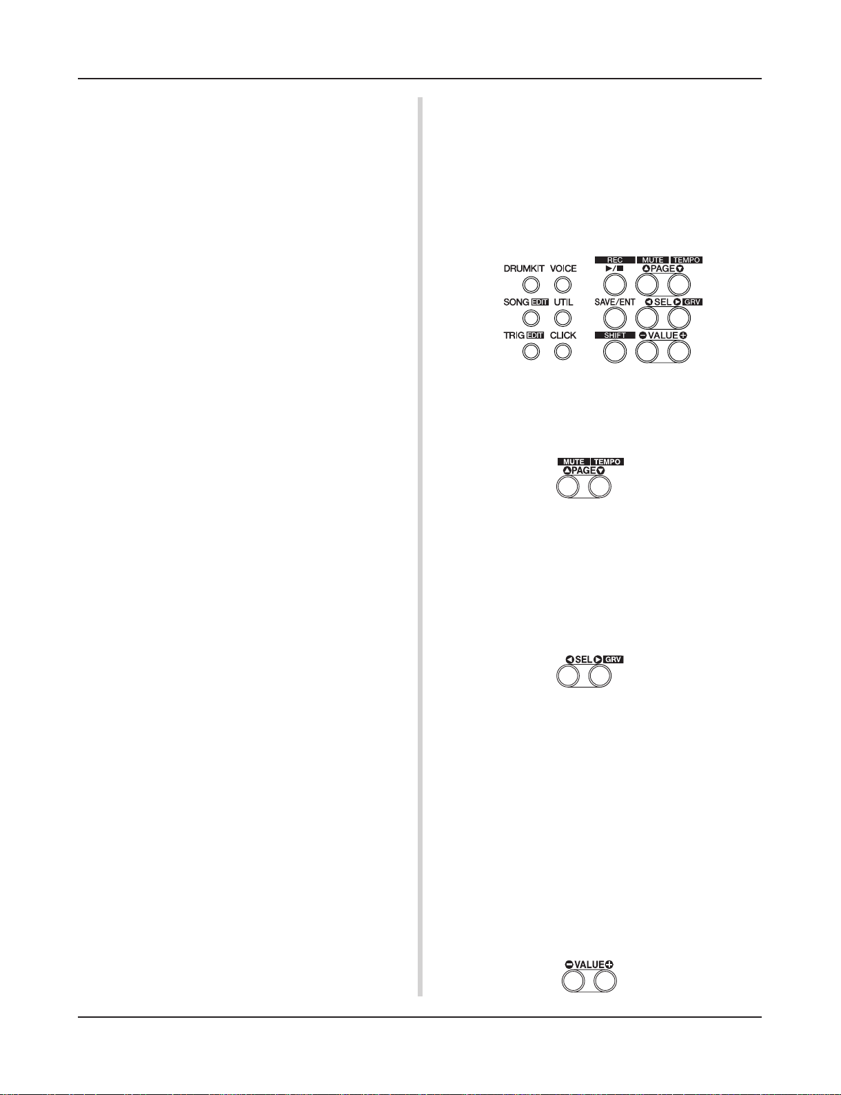
■ Basic Operations for Data Setting
● Enter the Modes
Press each Mode button or press while holding the [SHIFT] button.
• Drum Kit Play Mode …………………… [DRUMKIT]
• Trigger Setup Edit Mode …………….. [SHIFT]+[TRIG]
• Utility Mode ………………………………. [UTIL]
• Drum Kit Voice Edit Mode ………….. [VOICE]
• Song Edit Mode …………………………. [SHIFT]+[SONG]
● Page Navigation
Press the [PAGEs] button to move to the previous page, the
[PAGEt] button to move to the next page. Hold the button to
scroll through the pages.
● Select the Parameter
The flashing parameter on the display is specified for setting.
• Use the [SEL<] and [SEL>] buttons to move the cursor (the
flashing character or symbol).
The [SEL<] button moves the cursor to the left while the
[SEL>] moves the cursor to the right.
• When there is only one parameter on the display, the [SEL<]/
[SEL>] buttons will not operate.
● Change the setting
The setting (value) of flashing parameter on the display can be
changed.
• The [VALUE–] and [VALUE+] buttons are used to set parameter values.
When setting values, press the [VALUE–] button to decrease
(minus) the value, press the [VALUE+] button to increase (plus)
the value. Holding the button will continue to decrease/increase
the value.
Hold the [VALUE–] and press the [VALUE+] button will decrease the value by 10. Continue to hold both buttons and the
value will continue to decrease.
Hold the [VALUE+] button and press the [VALUE–] button to
increase the value by 10. Continue to hold both buttons and the
value will continue to increase.
5
Drum Kit Play Mode
This mode enables you to play the DTXPRESS II drum
voices by hitting the pads (or drums with trigger sensors attached) connected to the DTXPRESS II.
The DTXPRESS II automatically enters this mode when
the power is switched on.
You can select and play from 48 preset drum kits and 32
user kits.
Also, the drum kit, trigger setup and song specified in
this mode will be selected and ready for editing when
the Drum Kit Voice Edit, Trigger Setup Edit and Song
Edit modes are entered.
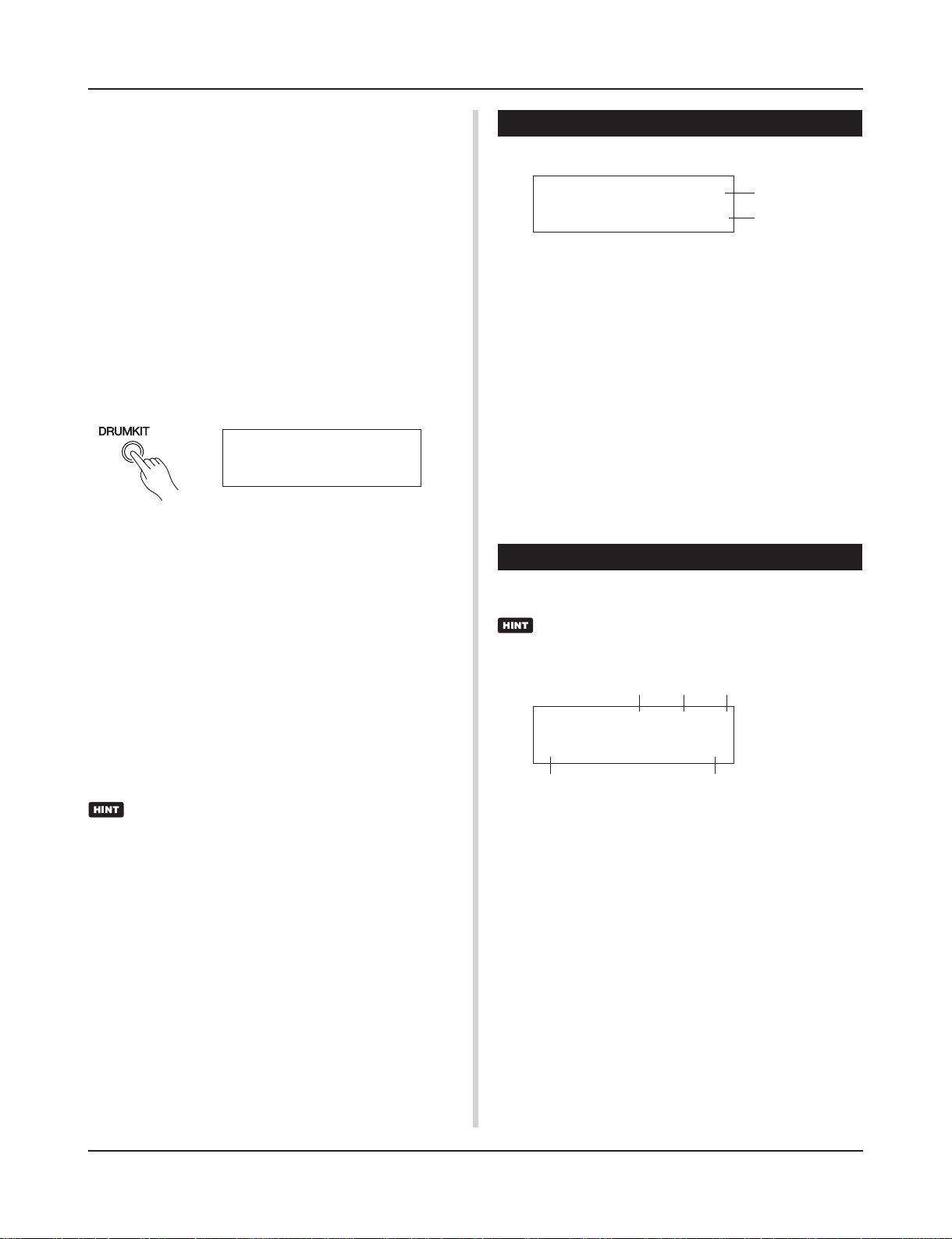
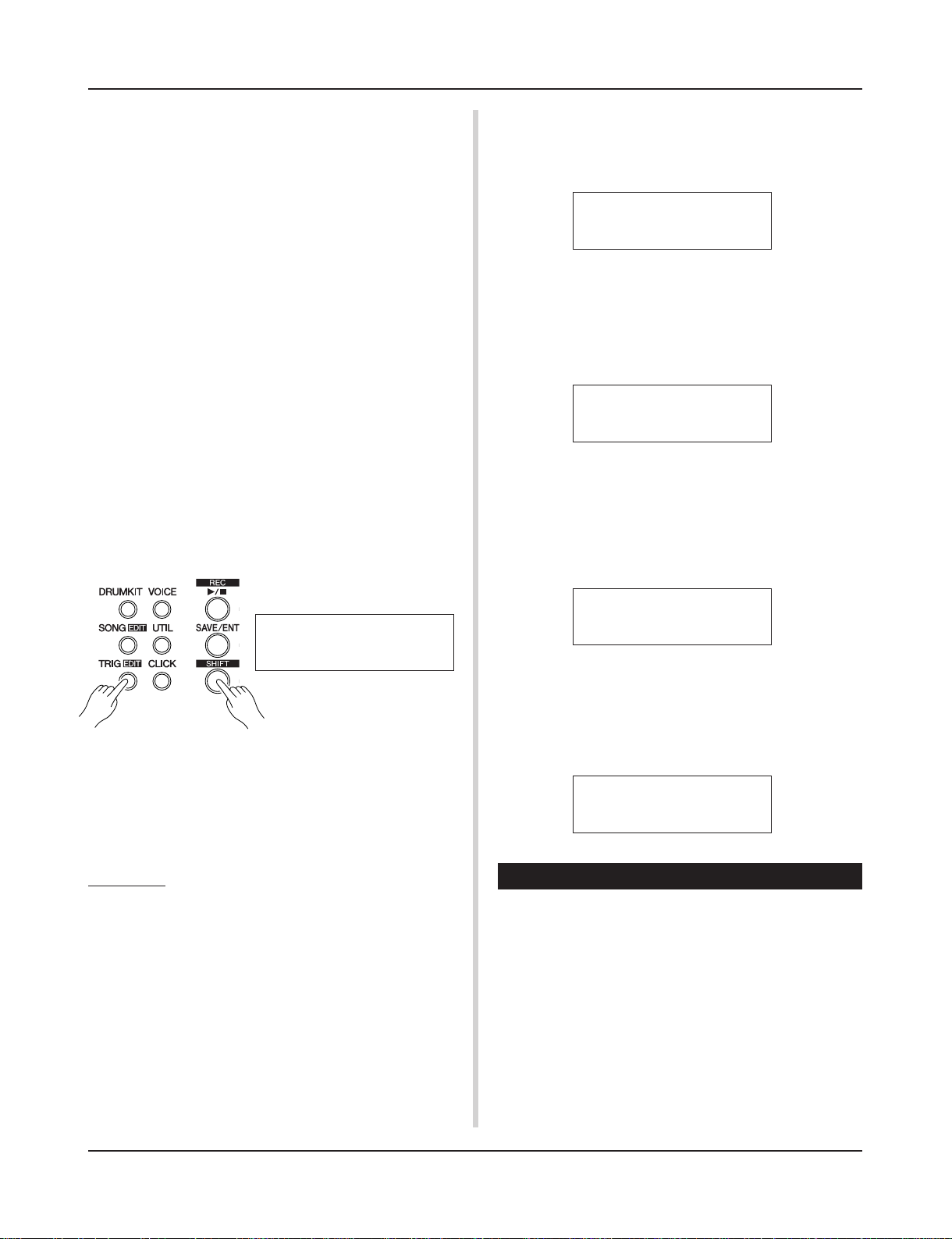
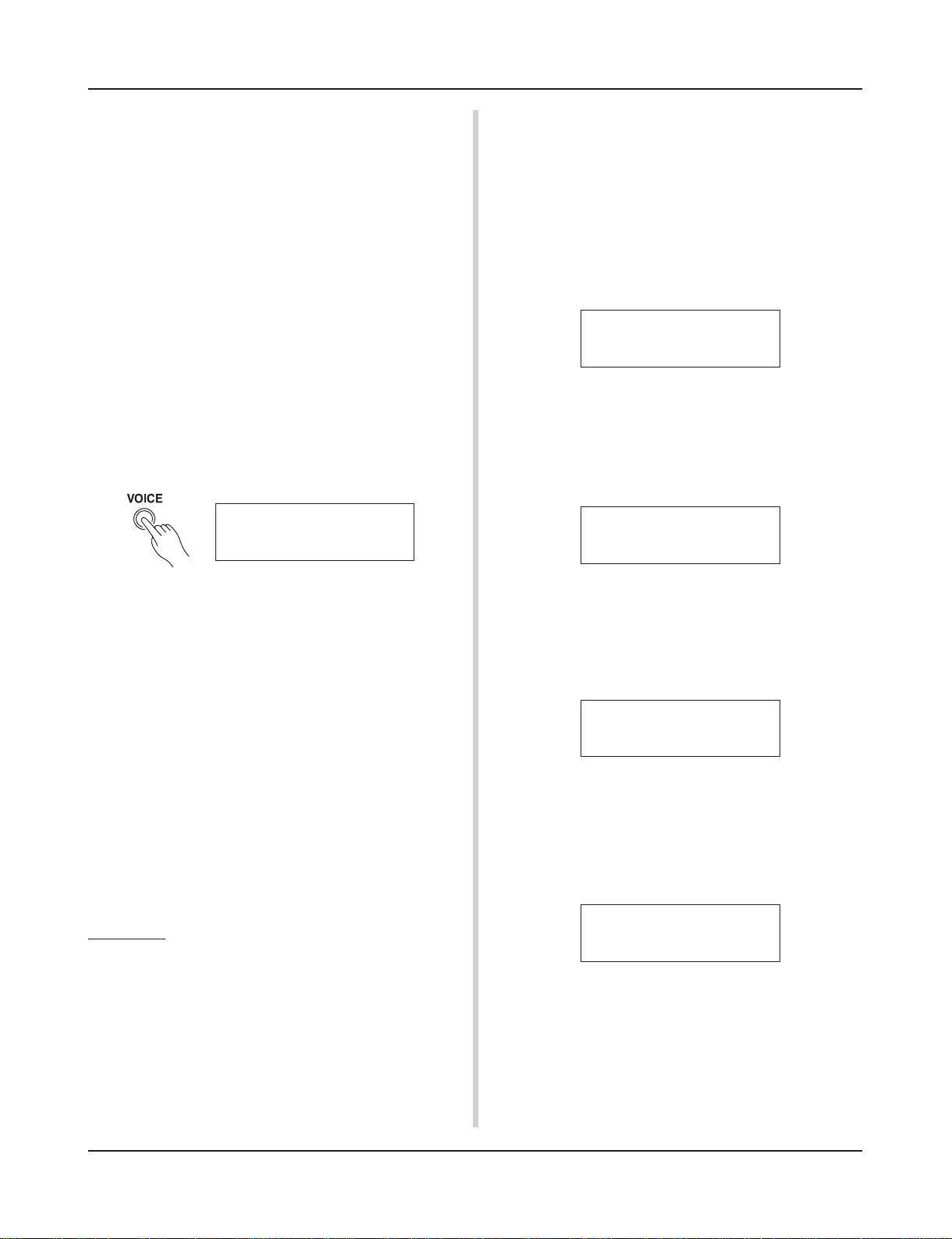
■ Entering the Drum Kit Play Mode
Press the [DRUMKIT] button on the front panel.
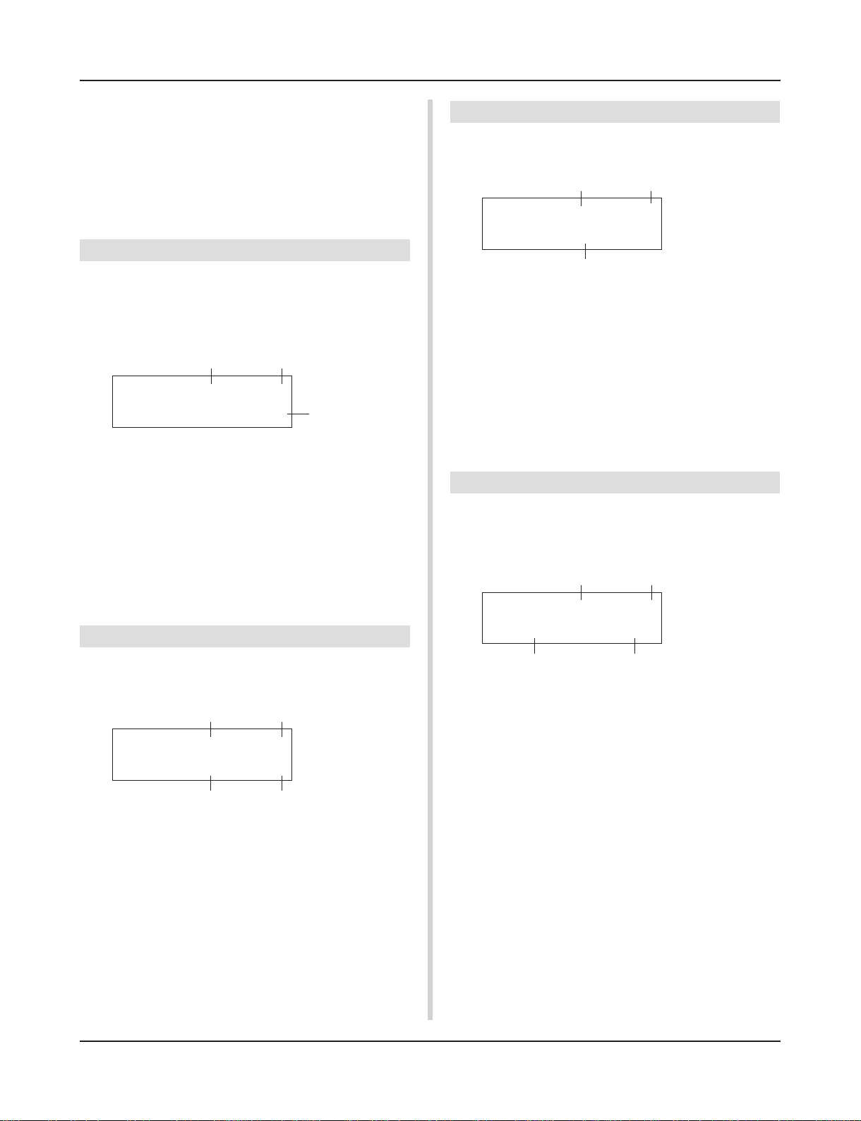
Once the Drum Kit Play mode is entered, the Song & Tempo display shown below will appear.
KIT ´´´´´´´´´´
1 Acoustic Kit
■ What’s in the Drum Kit Play Mode
The Drum Kit Play mode contains the three setting displays shown
below.
1. Drum Kit ………………………………………….. (P. 6)
This display is used for selecting the drum kit.
Press the [DRUMKIT] button to enter this display.
2. Song & Tempo …………………………………. (P. 6)
This display is used for selecting the song and
setting the song playback tempo.
Press the [SONG] button to enter this display.
3. Trigger Setup …………………………………… (P. 7)
This display is used for selecting the trigger setup.
Press the [TRIG] button to enter this display.
Press the [SHIFT]+[PAGEt] buttons, in any Drum Kit
Play mode display, to jump to the Song & Tempo display
with the cursor moved to tempo value.
1. Drum Kit
This display is used for selecting the drum kit.
KIT ´´´´´´´´´´
1 Acoustic Kit
q Velocity Meter
The input velocity for trigger inputs 1-10 is displayed using a bar
meter in the display.
w KIT (Drum Kit)
[Range] 1-80
Selects the drum kit. The drum kit number and drum kit name will
be displayed. Preset kits are numbered 1-48 and user kits are numbered 49-80.
When a pad is hit, the selected drum kit voice will be delivered.
Also, this drum kit will be specified for editing when the Drum
Kit Voice Edit mode is entered.
* Once a setting is changed in the Drum Kit Voice Edit mode, “*”
will appear between “KIT” and “=” until the data is stored.
* Refer to the [Preset Drum Kit List] (P. 42)
q
w
2. Song & Tempo
This display is used for selecting the song and setting the song
playback tempo.
Press the [SHIFT]+[PAGEt] buttons, in any Drum Kit
Play mode display, to jump to the following display with
the cursor moved to tempo value.
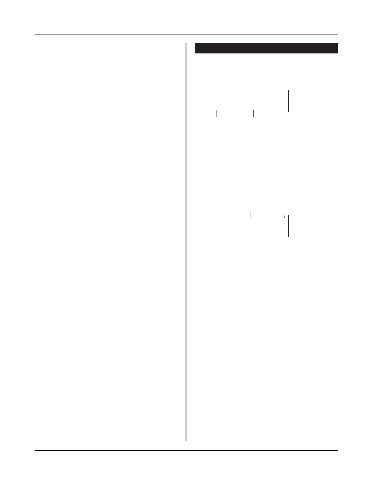
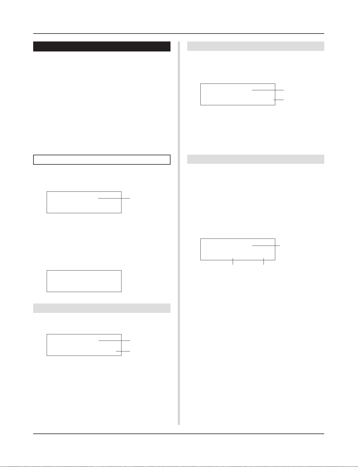
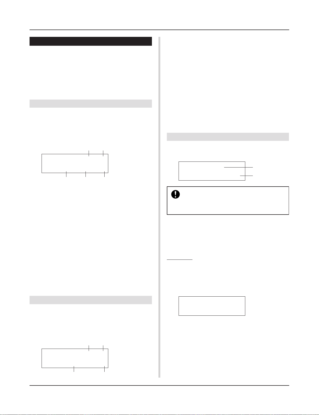
q w e
SONG ƒ=110 4/4= ƒ
1 HighRise -ß
r t
q q (Tempo)
[Range] 30-300, ext
Sets the playback tempo for the song.
When the DTXPRESS II is controlled by an external sync, “ext”
will be displayed.
* The external sync setting is found in [4-6. Sync Mode] (P. 34).
w Beat
[Range] 1/4-8/4, 1/8-16/8, 1/16-16/16
Sets the beat of the song (metronome).
e Metronome Note Value
[Range] When the beat w is set to 3/8, 6/8, 9/8, 12/8, 15/8, the
click tempo will be set to
ƒ quarter note, © eighth note, ˙ sixteenth note.
When the beat w is set to any value that is not listed
above, the click tempo will be set to
ƒ quarter note, ƒ3 quarter note (triplet),
6
Drum Kit Play Mode
© eighth note, ©3 eighth note (triplet),
˙ sixteenth note, ˙3 sixteenth note (triplet).
Use the note values to set the click tempo of the metronome.
r SONG
[Range] 1-127
Selects the song. The song number and song name will be displayed. Preset songs are numbered 1-95 and user songs are numbered 96-127.
The selected song will playback when the [>/■] button is pressed.
* When the rhythm mute ([SHIFT]+[PAGEs] is applied, the last
letter of the song name will be “˚”.
* Refer to [About the Song] (P. 8).
* Refer to the [Preset Song List] (P. 49).
t Repeat Playback
[Range] -ß, »Å
Sets the repeat playback (repeat continuously from the beginning
to the end of the song) of the song.
When this parameter is set to “»Å”, the song will repeat playback.
When this parameter is set to “-ß”, the song will playback normally.
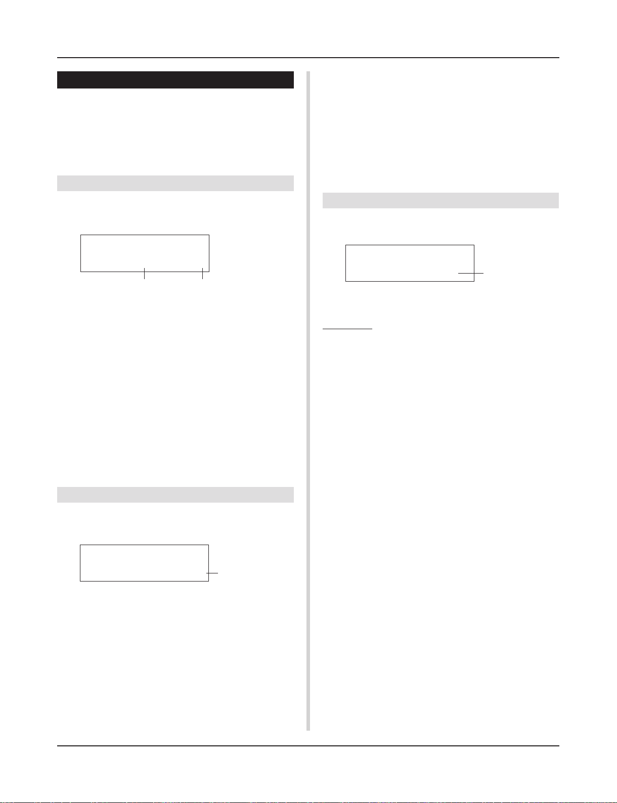
3. Trigger Setup
This display is used for selecting the trigger.
Groove Check Function
Function
As you play the pads along with a song, the DTXPRESS II
will compare your performance with its song clock and let
you know how accurate your timing is.
Display
In the Drum Kit Play mode (from any display) press the
[SHIFT]+[SEL>] (GRV) buttons.
* The Groove Check function will quit when song playback
is stopped.
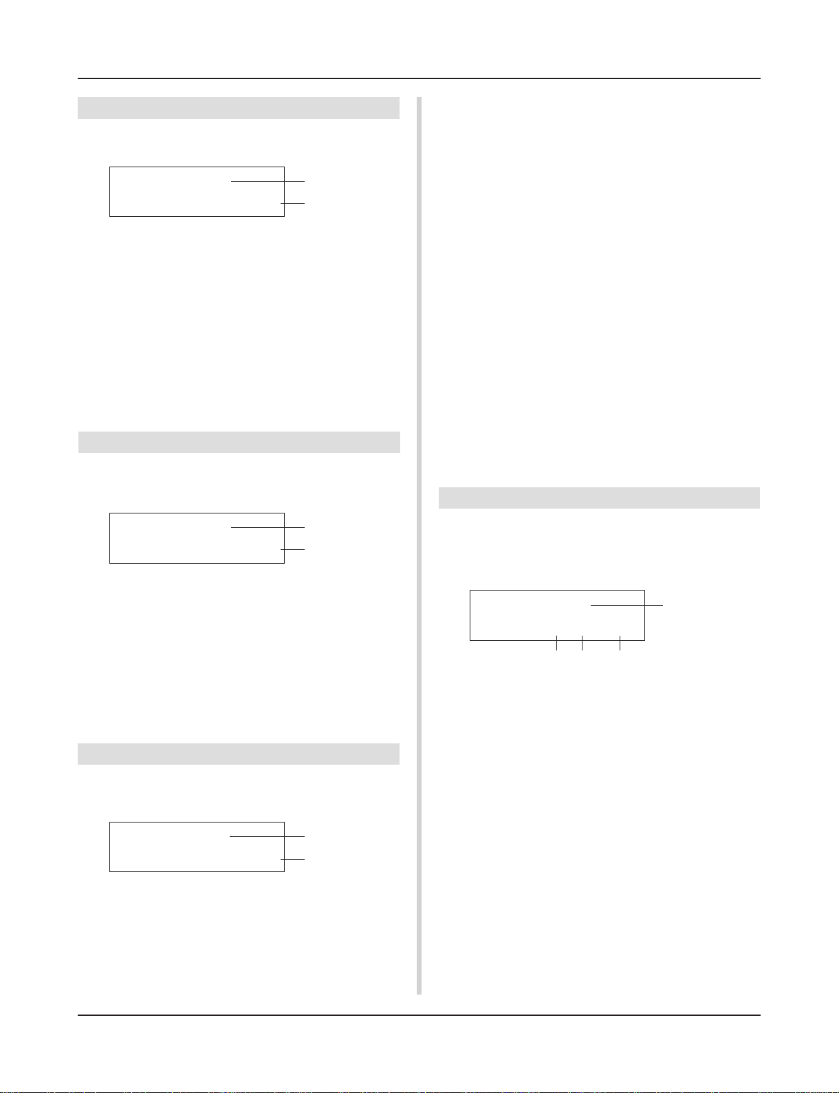
GRV ——¨——
e
Groov=0 Avg=0
q
q Groov (Groove)
[Range] –48 to 0 to +48
The difference in the timing of each stroke on the pad is displayed.
If the timing of the stroke is late compared to the just time, a
minus value will be displayed. If your timing is early, a plus
value will be displayed. If you timing is perfect, “0” will be
displayed.
w
TRIG ´´´´´´´´´´
q
1 Medium 1
w
q Velocity Meter
The input velocity for trigger inputs 1-10 is displayed using a bar
meter in the display.
w TRIG (Trigger Setup)
[Range] 1-9
Selects the trigger setup to be used. The trigger number and trigger name will be displayed. Presets are numbered 1-5 and user
setups are numbered 6-9.
* For more information on the preset trigger setup, refer to the
[Trigger Setup List] (P. 49).
* Once a setting is changed in the Trigger Edit mode, “*” will ap-
pear between “TRIG” and “=” until the data is stored.
e Trigger Input Number
[Range] 1-10
This number indicates the trigger input number of the pad that
was last struck.
e
w Avg (Average)
[Range] –48 to 0 to +48
This function displays the average value of your timing accuracy after the Groove Check function is switched ON.
This function checks your performance on the entire drum
set and can check your performance on one song. The information shown in the display is the same as in q Groov.
* To reset the data, press the [SHIFT]+[SEL>] buttons twice.
e Graph
Indicates the timing by means of a graph.
7
About the Song
The DTXPRESS II can internally store data for a maximum of
127 songs that can be played back freely.
Song numbers 1-95 are preset songs and song data in those songs
cannot be changed or rewritten.
Song numbers 96-127 are user songs that can be used to record
new performance data and also edit song data in.
■ Song Makeup
The Song consists of two sequencer tracks plus header data.
Header data is written at the front of the song and holds information related to the song’s tempo, beat, program numbers (voice)
for each MIDI channel and volume, etc. Header data is read every
time the song is played from the beginning.
Both tracks possess data for MIDI channels 1-16 (except system
exclusive data).
Durring song playback, the sequencer data that is written in the
song will be transmitted to the DTXPRESS II’s tone generator to
produce the song.
■ Main Song and Pad Song
Up to four songs can be played back simultaneously.
The song that is selected in the Drum Kit Play mode (P. 6) is called
the Main Song. Pressing the [>/■] button will start playback of
this song.
The remaining three songs are called Pad Song(s). These songs
are played back according to the trigger input (hitting a pad).
Song Playback
■ Main Song Playback
• Select a Song
1.
Press the [SONG] button to enter the Song & Tempo display.
SONG ƒ=110 4/4= ƒ
1 HighRise -ß
Song Number
2.
Use the [VALUE–]/[VALUE+] buttons to set the song number of the song you want to playback.
• Set the Tempo, Repeat Playback, Beat and Metronome
1.
In the previously selected Song & Tempo display, use
the [SEL<]/[SEL>] buttons to move the cursor to the
parameter you want to edit, then use the [VALUE–]/
[VALUE+] buttons to set the value.
Song Name
Tempo Beat Metronome Note Value
SONG ƒ=110 4/4= ƒ
1 HighRise -ß
Repeat Playback
■ Metronome
The sequencer produces the metronome.
The metronome can be used either alone or with the Song.
Press the [CLICK] button, in any mode, to start the metronome.
The metronome’s tempo, voice, etc. are set in the Utility mode [4.
Sequencer Group] (P. 33).
• Song Playback (Start/Stop)
Press the [>/■] button, in any display, to start playback of the
song (main song).
During playback, press the [>/■] button to stop playback of the
song. Press the [>/■] button again and the song will start play-
back from the beginning.
* If the pad’s function is previously set to the “Main Song Control”
function (m Drum Kit Voice Edit Mode [2-6. Function] P. 20), you
can start/stop the main song by hitting the assigned pad.
* During song playback, the [SONG] button’s LED will blink for a
moment at the beginning of each measure.
* During song playback, the song cannot be changed.
* If the song’s tempo or voices are irregular, re-select the song.
8

About the Song
■ Pad Song Playback (Start/Stop)
To playback a Pad Song, hit the pad that is assigned to the Pad
Song you want to playback. Hit the same pad during playback will
stop the song. Hit the pad again to start the song from the beginning.
* Before using, set the pad’s function to “Pad Song Control” and
assign a song to the pad (m Drum Kit Voice Edit mode [2-6.
Function], [2-7. Pad Song] P. 20).
* The song can be played one measure at a time, each measure
triggered with a stroke on the pad (m Drum Kit Voice Edit mode
[2-7. Pad Song] P. 20)
* If the Pad Song’s tempo or voices are irregular, re-select the
Drum Kit.
■ Song Playback Functions
During song playback, the song can be repeated and volume levels for each instrument can be changed.
• Volume Control
With each of the knobs on the front panel, the following volume
levels can be controlled.
• [ACCOMP VOL]: The volume of the accompaniment (voices
other than drum voices).
• [SHIFT]+[ACCOMP VOL]: The volume of the snare drum.
• [CLICK VOL]: The volume of the metronome’s click.
• [SHIFT]+[CLICK VOL]: the volume of the bass drum.
If the Utility mode’s [2-3. Volume Mode] (P. 29) is set to “live”,
the following volume levels can be controlled.
• [ACCOMP VOL]: The volume of the snare drum.
• [SHIFT]+[ACCOMP VOL]: The volume of the cymbal.
• [CLICK VOL]: The volume of the bass drum.
• [SHIFT]+[CLICK VOL]: The volume of the other drum instruments.
• Rhythm Mute Function
When the [SHIFT]+[PAGEs] buttons are pressed, the MIDI channels (usually channel 10) that are assigned to track 1 of the song
and the drum voice will be muted (sound will not be delivered).
* When the Rhythm Mute is applied, program changes will be ig-
nored so the drum kit cannot be changed.
• Other Functions
• This function can set whether the song will playback according to the tempo information in the song or according to the
tempo that is set when the song is switched. (m P. 35 [4-7.
Use Tempo])
• This function can set whether or not the click voice will be
delivered automatically when the song is played back. (m P.
35 [4-8. Click Mode])
• The metronome’s click voice can be switched ON/OFF by hitting the pad. (m P. 20 [2-6. Function])
• Set the Metronome
The voice, pitch and MIDI note number of the metronome’s click
voice can be set. ([4-1. Click Voice] (P. 33), [4-2. Click Tune] (P.
34), [4-3. Click Note Number] (P. 34)
• Count Function
If the Utility mode’s [4-5. Count Switch] (P. 34) is set to “on”
when the main song is played back, the first measure of the song
will be preceded by a two measure count.
• MIDI Control by an External Device
• If the Utility mode’s [4-4. MIDI Control] (P. 34) is set to “on”,
playback of the main song can be controlled with system realtime messages (start/continue/stop) from the MIDI IN/TO
HOST jack.
• If the Utility mode’s [4-6. Sync Mode] (P. 34) is set to “ext”
or “auto”, the song playback can be synchronized to the clock
of an external MIDI device.
9

About the Song
Song Recording
Song recording lets you record data, produced as the drum kit is
played, to the sequencer in real-time (one track at a time). All MIDI
channels (1-16) are recorded simultaneously. Also, data produced
by a MIDI keyboard connected to the MIDI IN jack can be recorded as well as sequencer data received via the MIDI IN/TO
HOST jacks.
According to the recorded sequencer data (performance information), drum kits and voices can be changed during song playback.
The songs that are recorded can be played back and edited in the
same manner as preset songs (No. 1-48) with the Song Edit mode.
■ Song Record Settings
• Select the Song
1.
Press the [SONG] button to display the Song & Tempo
display, select the User Song number (No. 96-127) that
you want to record to.
* Only User Songs (No. 96-127) can be use d for recording.
Preset Songs (No. 1-95) cannot be used for recording.
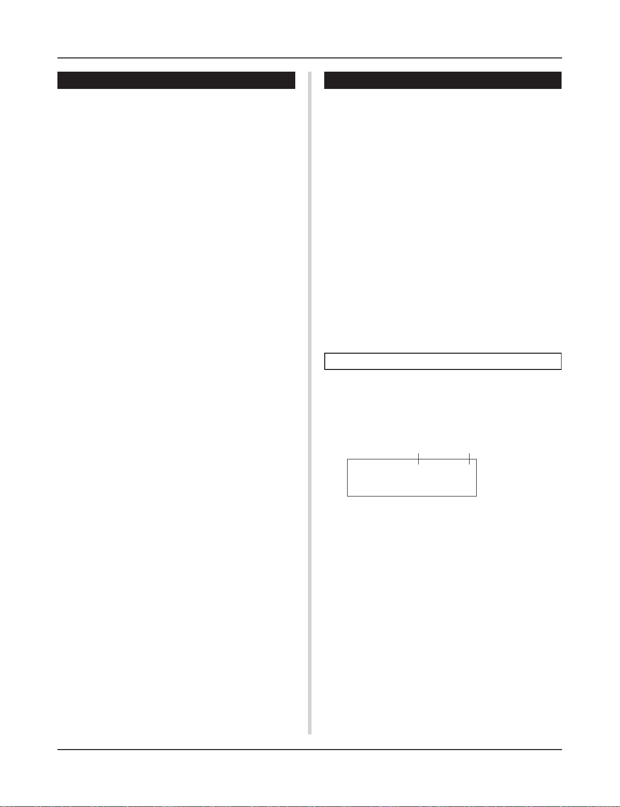
• Set the Recording Conditions (Record Standby)
2.
Press the [SHIFT]+[>/■] buttons, the record mode will
be in standby. The following display will appear.
q w e
REC M= 32=Rp1†=1
ƒ=120 B= 4/4Q= ©
r y
3.
Use the display shown above to set the following recording conditions.
q M (the number of measures that will be recorded)
[Range] 1-999
Assigns the number of measures that will be recorded. When
there is data in the other track, the number of measures in that
track will decide the length of the song and this length cannot
be changed.
w Record Mode
Select the method of recording from the following.
Overwrite (Ovr): The record operation will be in a repeat
mode. When the song reaches the end of the last measure, it
will automatically start again from the beginning and new
data will be added to the track’s previous data.
Replace (Rpl): When the song reaches the end of the mea-
sure number assigned in “M” or the [>/■] button is pressed,
recording will stop (the song will not repeat).
e TR (Specify the Track for Recording)
Selects which track (“1” or “2”) will be recorded.
r q (Metronome Tempo) [Range] 30-300
Sets the metronome tempo for recording
t B (Beat) [Range] 1/4-8/4, 1/8-16/8, 1/16-16/16
Sets the beat of the song (metronome) for recording.
t
y Q (Quantize Accuracy)
[Range] ƒ quarter note, ƒ3 quarter note (triplet)
© eighth note, ©3 eighth note (triplet)
˙ sixteenth note, ˙3 sixteenth note (triplet), no
The Quantize function* can be used when recording.
When set to “no”, the Quantize function will not operate.
Quantize: This function is used to correct the timing of recorded
MIDI note data. The accuracy of quantization is assigned
by the note value.
* You can also use the Quantize function after recording is com-
plete. (Song Edit mode [5. Quantize] P. 25)
• Record
4.
Press the [>/■] button to start recording.
* If the Utility mode’s [4-4. MIDI Control] (P. 34) is set to “on”,
the recording operation can be started with a system real
time message (start) received via the MIDI IN/TO HOST jacks.
* When the track assigned for recording contains data and the
[>/■ ] button is pressed, the error message “Data not
Empty” will appear and the recording operation will not be
carried out.
While the song is recording, the following display will appear
(only displayed, cannot change).
• When the Record Mode = Replace (“Rpl”)
REC M= 5=Rp†=1
Now Recording.
• When the Record Mode = Overwrite (“Ovr”)
REC M= 5=Ovr†=1
UNDO press ENT
• Next to “M=” the measure number currently being recorded is
displayed.
• When the Record mode is set to “Ovr”, press the [SAVE/
ENT] button to “Undo” (do again) the record operation. Press
the [SAVE/ENT] button while recording to start recording from
the top of the song. The data previously recorded from the
beginning of the song, up until the [SAVE/ENT] button was
pressed, will revert to the data originally present.
• Stop Recording
5.
When the song reaches the end of the assigned measure number, recording will automatically stop and the
DTXPRESS II will return to the Song & Tempo display.
* Recording can also be stopped anytime by pressing the [>/
■] button.
* If the power is switched off while recording, all the data in the
User Song may be lost. Please use caution.
Data recorded in the tracks cannot be overwritten. To
record new data, use the Song Edit mode’s [6. Clear Track]
(P. 26) or [8. Clear Song] (P. 26) operations to erase track
data.
10
Trigger Setup Edit Mode
This mode contains various settings related to trigger
input from the pads and trigger sensors that are connected to the DTXPRESS II.
It allows you to adjust pad sensitivity and assign drum
voices to each trigger input. Trigger Setup data consists
of five preset types (No. 1-5) and four original setup types
(No. 6-9) for storing user setup data.
■ What you can do with the Trigger Setup Edit
Mode
The Trigger Setup Edit Mode lets you alter a variety of settings for
each of the trigger inputs jacks (1-10) of the Trigger Setup.
You can edit both preset (No. 1-5) and user Trigger Setups (No. 6-
9).
The edited Trigger Setup can be stored in a User Trigger Setup
(No. 6-9) using the Store Operation.
* Selecting another Trigger Setup before storing your changes
will result in the data reverting to its default settings.
* Data cannot be stored to preset Trigger Setup (No. 1- 5).
■ Entering the Trigger Setup Edit Mode
Hold the [SHIFT] button and press the [TRIG] button on the front
panel.
Once the Trigger Setup Edit Mode is entered, the INPUT
parameter’s main page (pad type), shown below, will be displayed.
5.
Use the [VALUE–], [VALUE+] buttons to set the
parameter’s value or ON/OFF setting.
* Once a setting is changed, “*” will appear on the display next
to “TRIG”. After data is saved, the mark will disappear.
TRIG*IN= 1
Type= KP
6.
To store changes in the User Trigger Setup, use the following procedure.
* The changes you made will be lost if another trigger setup is
selected before your changes have been stored.
6-1. Press the [SAVE/ENT] button. The following display will
appear.
Store Trigger
To= 6 InitTrig
6-2. Use the [VALUE–], [VALUE+] buttons to assign the User
Trigger Setup number (6-9) (located next to “To=”) for
storing your changes. The number and setup name will
appear.
6-3. Press the [SAVE/ENT] button, the following display will
appear asking for confirmation before the store operation is carried out.
TRIG IN= 1
Type= KP
■ What’s in the Trigger Setup Edit Mode
The Trigger Setup Edit Mode is divided into two sub-groups.
1. INPUT Parameters …………………………. mP. 1 2
Contains specific settings for each pad (1-10).
2. COMMON Parameters ……………………. mP. 1 4
Contains common settings for all pad inputs.
Procedure
1.
Press the [TRIG] button to enter the Trigger Setup display, then select the trigger setup you want to edit.
2.
Hold the [SHIFT] button and press the [TRIG] button to
enter the Trigger Setup Edit mode.
3.
Use the [PAGE▲], [PAGE▼] buttons to display the list
you want to edit.
* If the Utility mode’s [2-4. Jump to Recent Page] parameter (P.
29) is set to “on”, the DTXPRESS II will display the page last
edited when entering the Trigger Setup Edit mode.
4.
Use the [SEL<], [SEL>] buttons to move the cursor to
the list you want to edit. The list will flash.
* If there is only one list, it is not necessary to move the cursor.
Store TRG to 6
Are you sure ?
6-4. Press the [SAVE/ENT] or [VALUE+] button, the store
operation will be carried out.
* Press the [VALUE–] button to cancel the store opera-
tion.
The following display will appear after the store operation is completed.
Complete !
Trigger Setup Edit Mode Function List
Page
1. INPUT Parameters ………………………………………….. 12
1-1. Pad Type …………………………………………………. 12
1-2. Gain, Minimum Velocity …………………………….. 12
1-3. Velocity Curve …………………………………………. 13
1-4. Self Rejection, Rejection …………………………… 13
1-5. Specific Rejection …………………………………….. 13
1-6. Copy Input ………………………………………………. 13
2. COMMON Parameters …………………………………….. 14
2-1. Increment/Decrement ……………………………….. 14
2-2. Input Exchange ……………………………………….. 14
2-3. Trigger Setup Name …………………………………. 14
11
Trigger Setup Edit Mode
1. INPUT Parameters
Contains specific settings for each of the pads (1-10).
This function is divided into the following 6 pages.
1-1. Pad Type …………………………………………………. 12
1-2. Gain, Minimum Velocity …………………………….. 12
1-3. Velocity Curve …………………………………………. 13
1-4. Self Rejection, Rejection …………………………… 13
1-5. Specific Rejection …………………………………….. 13
1-6. Trigger Setup Copy …………………………………… 13
1-1. Pad Type
Sets the type of pad or trigger sensor that is connected to the trigger input jack q. By selecting the appropriate pad type, pad functions can be used to their full potential.
TRIG IN= 1
Type= KP
q TRIG IN (Trigger Input Number)
[Range] 1-10
Assigns the trigger input jack number for the pad you want to edit.
* According to the setting in the utility mode’s [2-1. Learn Mode]
(P. 29) trigger input jack numbers can be assigned by hitting the pad.
w Type (Pad Type)
Sets the type of pad that is connected to the trigger input jack
assigned in q TRIG IN.
* Values set in [1-2. Gain, Minimum Velocity] (P. 12) and [1-4. Self
Rejection] (P. 13) will automatically select the proper value for
the pad type you set here.
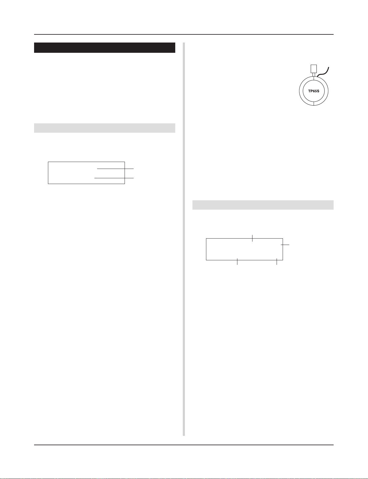
* The “HH contrler” can only be assigned to Input Jack 1. Con-
nect the Hi-hat Controller HH60, HH80 or HH80A to Input Jack 1
and set to “HH contrler” to use in place of a kick pedal.
Use a cable with a stereo plug when connecting a Hi-hat controller.
Pad types are defined as follows.
KP KP80S/80/65/60, SKP120
TP65-1 TP65S/65 (mainly used as a snare pad) *1
TP65-2 TP65S/65 (mainly used as a tom pad) *1
TP80-1 TP80S/80 *2
TP80-2 TP80S/80 *2
TP60 TP60
RHP pad RHP series (pad side) *3
RHP rim RHP series (rim side) *3
SHP-1 SHP series (mainly used as a snare pad) *1
SHP-2 SHP series (mainly used as a tom pad) *1
PCY65 PCY65S/65
PCY80 PCY80S/80
PCY60 PCY60
PCY10 PCY10
PCY150 PCY150 *4
RHH RHH120
BP80 BP80 *5
DT snare DT series drum trigger (for a snare drum)
DT hi tom DT series drum trigger (for small toms)
DT lo tom DT series drum trigger (for large toms)
DT kick 1 DT series drum trigger (for a bass drum)
misc 1 — 6 Another manufacturer’s pad 1 — 6.
q
w
HH contrler
HH series controller connected to Input 1 and
used as a kick pedal.
*1 When the TP65S/SP is connected to Input
2/6/7, its 3-zone function is available (pad
x 1, rim sound x 2). If the pad is connected
to any other input, the rim will produce only
one sound.
For closed rim shots, the sensitivity for rim
1 on the TP65-1 and SHP-1 is set to high.
Sensitivity settings for right and left rims
are the same on the TP65-2 and SHP-2.
*2 When the TP80S is connected to Input 2/6/7, the voice assigned
to rim 1 will be produced by the TP80-1 (Input 2:snrR1, Input
6:rideE, Input 7:crashE) while the voice assigned to rim 2 will
be produced by the TP80-2 (Input 2:snrR2, Input 6:rideC, Input
7:crashC). (Refer to page 16.)
*3 To use an RHP series pad as a stereo pad, connect to Input 9/10
and set the pad type on Input 9 to RHP pad and the pad type on
Input 10 to RHP rim.
*4 When the PCY150 is connected to Input 2/6/7, 3-zone function is
available.
*5 To use the BP80 as a stereo pad, connect the pad to Input 9/10.
Rim 1Rim 2
1-2. Gain, Minimum Velocity
This function sets the input sensitivity (Gain) and velocity range
(Minimum Velocity) for each input jack q.
q
TRIG IN= 1 ( 0%)
Level Display
Gain=64 MVel= 32
w
q TRIG IN (Trigger Input Number)
Assigns the trigger input jack number. (The same procedure as in
[1-1. Pad Type]).
w GAIN (Input Gain)
[Range] 0-99
Adjusts the input gain level (minimum sensitivity) for the trigger
input jack assigned in step q TRIG IN.
Entering a larger value here allows smaller input levels to sound
the voice.
* This value will be automatically set after the appropriate pad
type is set in [1-1. Pad Type]. Some fine-tuning of the value will
be necessary.
e MVel (Minimum Velocity)
[Range] 1-127
Sets the MIDI Velocity (volume) that is transmitted when the pad
is hit the weakest. Large values will produce a high volume level
even if the pad is hit softly. However, this will result in a narrow
volume range making it difficult to adequately produce wider dynamic levels.
If “
HH contrler
” is set for the pad type, the value set here will
be transmitted as the velocity.
The trigger input level will be displayed as a % in the upper right
e
12
Trigger Setup Edit Mode
hand corner of the display. The maximum velocity (input level
99%) will be 127. The level is low when the pad is hit the weakest
so a wider dynamic range will be possible.
* This value will be automatically set after the appropriate pad
type is set in [1-1. Pad Type]. Some fine-tuning of the value will
be necessary.
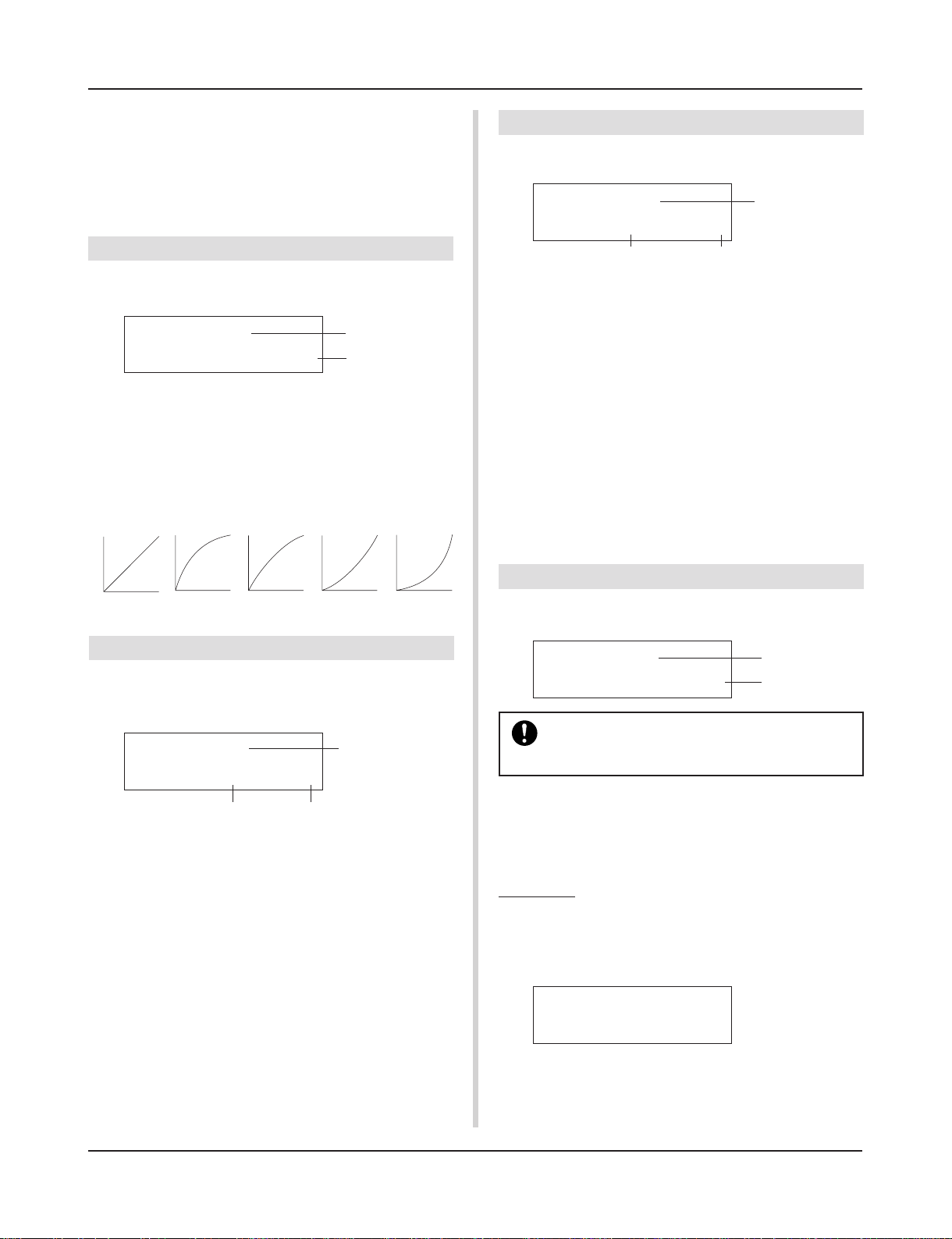
1-3. Velocity Curve
This function sets the MIDI Velocity Curve for the sensitivity for
each input jack q.
TRIG IN= 1
VelCurve= normal
q TRIG IN (Trigger Input Number)
Assigns the trigger input jack number (the same procedure as in
[1-1. Pad Type]).
w VelCurve (Velocity Curve)
Sets the Input Velocity Curve for the trigger input jack assigned in
TRIG IN q.
normal
m
Velocity
loud1loud 2
q
w
hard 1
hard 2
1-5. Specific Rejection
This function prevents cross talk from occurring between two specified input jacks q and e.
TRIG IN= 1
q
SPCRej=0 frm= 1
w
q TRIG IN (Trigger Input Number)
Assigns the trigger input jack number (the same procedure as in
[1-1. Pad Type]).
w SPCRej (Specific Rejection)
[Range] 0-9
After an event occurs from the pad from the input jack assigned in
e, the pad of the input jack assigned in TRIG IN q will not
sound for a certain length of time unless the level is greater than
the value assigned here.
e frm (Assigned Destination Trigger Input Number)
[Range] 1-10, 6&7
Sets the destination trigger input jack number of the pad that will
be rejected. When “6&7” is selected, both trigger inputs 6 and 7
will be assigned.
e
Strength
of hitm
1-4. Self Rejection, Rejection
This function is used to prevent double triggers* and cross talk
(mixed input signals between the jacks) for each input jack q.
* double trigger: When 2 sounds are played at the same time.
TRIG IN= 1
q
SelfRej=2 Rej= 3
w e
q TRIG IN (Trigger Input Number)
Assigns the trigger input jack number (the same procedure as in
[1-1. Pad Type]).
w SelfRej (Self Rejection)
[Range] 0-9
Prevents double triggers from occuring in the input jack assigned
in TRIG IN q. After an event is detected, further events will be
automatically muted for a certain length of time. Larger values set
longer times.
e Rej (Rejection)
[Range] 0-9
Prevents cross talk from occuring in the input jack assigned in
TRIG IN q. Events triggered by other pads (input jacks) that are
of a lower input value than what is set here will not be delivered
for a set length of time.
1-6. Trigger Setup Copy
This function copies all data settings in [1-1. Pad Type] to [1-5.
Specific Rejection] from input jack q to another input jack w.
TRIG IN= 1
Copy to Input= 1
When the Trigger Setup Copy operation is carried
out, the trigger setup data will be replaced with the
settings of the copy source.
q TRIG IN (Trigger Input Number)
Sets the trigger input jack number (1-10) of the pad copy source.
w Copy to Input (
Sets the trigger input jack number (1-10) of the copy destination.
Trigger Input Number Copy Destination
q
w
Procedure
1.
In the display shown above, assign the copy source and
copy destination, press the [SAVE/ENT] button. The following display will appear asking for confirmation before
the copy operation is carried out.
Input Copy to 1
Are you sure ?
2.
Press the [SAVE/ENT] or [VALUE+] button, the copy
operation will be carried out.
* Press the [VALUE-] button to cancel the copy operation.
When the copy operation is complete, “Complete!” will appear.
)
13
Trigger Setup Edit Mode
2. COMMON Parameters
Contains common settings for all pad inputs (1-10).
This group is divided into the following 3 pages.
2-1. Increment/Decrement ……………………………….. 14
2-2. Input Exchange ……………………………………….. 14
2-3. Trigger Setup Name …………………………………. 14
2-1. Increment/Decrement
This sets the pad function that allows the currently selected drum
kit number to be increased or decreased by 1 by hitting the specified pad.
TRIG Common
IncIn= 4DecIn= 5
q w
q Incin (Pad for Increment)
[Range] —, 1-10
Assigns the trigger input jack number that is set for the increment
(+1) function. “—” will appear when this function is not assigned
to the pad.
w Decin (Pad for Decrement)
[Range] —, 1-10
Assigns the trigger input jack number that is set for the decrement
(-1) function. “—” will appear when this function is not assigned
to the pad.
* Even when the drum kit is changed, the pads connected to the
assigned trigger input jacks will retain their increment/decrement functions. To assign this function to each drum kit, refer to
the Drum Kit Voice Edit mode’s [2-6. Function] (P. 20)
2-2. Input Exchange
When the input jack 9 pad is hit.
m This event will be recognized as a signal from the input jack
1 pad (as if a trigger were received from input jack 1) and
operate accordingly.
When the input jack 10 pad is hit.
m This event will be recognized as a signal from the input jack
9 pad (as if a trigger were received from input jack 9) and
operate accordingly.
2-3. Trigger Setup Name
Changes the name of the currently selected (currently being edited) Trigger Setup.
TRIG Common
TrgName=Medium
q TrgName (Trigger Setup Name)
Procedure
1.
In the display shown above, use the [SEL<]/[SEL>] buttons to move the cursor to the character you want to
change.
2.
Use the [VALUE–]/[VALUE+] buttons to select the alphabet, number or symbol.
3.
Repeat steps 1 and 2 above to create the Trigger Setup
name using a maximum of 8 characters.
● The available characters to choose from are (in order):
space
!»#$%&'()*+,-./0123456789:;<=>?@
ABCDEFGHIJKLMNOPQRSTUVWXYZ[\]^_`
abcdefghijklmnopqrstuvwxyz{|}ßå
q
Switches the trigger signal from the pads between trigger input
jacks 1 and 9/10.
TRIG Common
In Excg= normal
q In Excg (Input Exchange)
normal: Normal operation.
In10,1/9: The signals from Input Jacks 1 and 9/10 are switched.
When the input jack 1 pad is hit.
m This event will be recognized as a signal from the input jack
10 pad (as if a trigger were received from input jack 10) and
operate accordingly.
When the input jack 1 rim is hit.
m Normal operation. This event will be recognized as a signal
from the input jack 1 rim.
14
q
Drum Kit Voice Edit Mode
This mode lets you set which voice and how it will be
triggered for each pad (trigger input source) in the currently selected drum kit.
■ What you can do with the Drum Kit Voice
Edit Mode
This mode contains various settings related to the currently selected drum kit (data in the edit buffer for the drum kit).
You can edit both preset (No. 1-48) and user drum kits (No. 49-
80).
The edited drum kit can be stored in a User Drum Kit (No. 49-80)
using the Store Operation.
* Selecting another drum kit before storing your changes will re-
sult in the data reverting to its default settings.
* Data cannot be stored to preset drum kits (No. 1- 48).
■ Entering the Drum Kit Voice Edit Mode
Press the [VOICE] button on the front panel.
Once the Drum Kit Voice Edit Mode is entered, the Voice Parameter main page (Voice) shown below will be displayed.
KIT IN=kick V=1
=K/017 BDaftty1
4.
Use the [SEL<]/[SEL>] buttons to move the cursor to
the parameter you want to edit. The parameter will flash.
* If there is only one parameter, it is not necessary to move the
cursor.
5.
Use the [VALUE–]/[VALUE+] buttons to set the
parameter’s value or ON/OFF setting. Pressing the
[VOICE] button lets you listen to the Drum Kit Voice while
editing.
* Once a setting is changed, “*” will appear on the display next
to “KIT”. After data is stored, the mark will disappear.
KIT*IN=kick V=1
=K/019 MapleA20
6.
To store your changes in a User Drum Kit, use the Store
Operation described below.
* The changes you made will be lost if another drum kit is se-
lected before your changes have been stored.
6-1. Press the [SAVE/ENT] button. The following display will
appear.
Store Drumkit
=49 User Kit
■ What’s in the Drum Kit Voice Edit Mode
The Drum Kit Voice edit Mode is divided into the following five
sub-groups.
1.Voice Parameters………………………… (m P. 16)
Sets the voice for each input source of the pad.
2. Input Common Parameters …………. (m P. 19)
Common settings related to the 2 layers for each
pad input source’s voice parameter.
3. Reverb Parameters …………………….. (m P. 21)
Sets the internal reverb effect.
4. Setup…………………………………………. (m P. 22)
When the drum kit is selected, this function copies the drum kit voice settings and MIDI transmit
settings.
5. Drum Kit Common Parameters …… (m P. 23)
Common settings for the entire drum kit.
Procedure
1.
Press the [DRUMKIT] button to enter the Drum Kit display, then select the drum kit you want to edit.
2.
Press the [VOICE] button to enter the Drum Kit Voice
Edit Mode.
3.
Use the [PAGEs], [PAGEt] buttons to display the page
you want to edit.
* If the Utility Mode’s [2- 4. Jump to Recent Page] (P. 29) pa-
rameter is set to “on”, the DTXPRESS II will display the page
last edited when entering the Drum Kit Voice Edit Mode.
6-2. Use the [VALUE-]/[VALUE+] buttons to assign the Drum
Kit number (49-80) (located next to “To=”). The number and drum kit name will appear.
6-3. Press the [SAVE/ENT] button, the following display will
appear asking for confirmation before the store operation is carried out.
Store KIT to= 49
Are you sure ?
6-4. Press the [SAVE/ENT] or [VALUE+] button, the store
operation will be carried out.
* Press the [VALUE-] button to cancel the store opera-
tion.
The following display will appear after the store operation is complete.
Complete !
15
Drum Kit Voice Edit Mode
Drum Kit Voice Edit Mode Function List
Page
1. Voice Parameters……………………………………………. 16
1-1. Voice………………………………………………………. 17
1-2. Volume, Pan ……………………………………………. 17
1-3. Tuning…………………………………………………….. 17
1-4. Layer Balance………………………………………….. 18
1-5. Decay, Cutoff Frequency …………………………… 18
1-6. Note Number …………………………………………… 18
1-7. Channel, Gate Time …………………………………. 18
2. Input Common Parameters……………………………… 19
2-1. Cross Fade ……………………………………………… 19
2-2. Reverb Send……………………………………………. 19
2-3. Alternate Group, Key Assign Mode …………….. 19
2-4. Hold Mode ………………………………………………. 20
2-5. Key Off Enable ………………………………………… 20
2-6. Function ………………………………………………….. 20
2-7. Pad Song ………………………………………………… 20
2-8. Rim to Pad ………………………………………………. 21
3. Reverb Parameters…………………………………………. 21
3-1. Reverb Type, Time ……………………………………. 21
3-2. Reverb Master Return ………………………………. 21
4. Setup …………………………………………………………….. 22
4-1. Program Change, Bank Select …………………… 22
4-2. Volume, Pan ……………………………………………. 22
4-3. Drum Kit Voice Copy ………………………………… 22
5. Drum Kit Common Parameters ……………………….. 23
5-1. Volume …………………………………………………… 23
5-2. Drum Reverb Send …………………………………… 23
5-3. Hi-Hat Sensitivity ……………………………………… 23
5-4. Song Select …………………………………………….. 23
5-5. Drum Kit Name ………………………………………… 23
1. Voice Parameters
Sets the voice for each input source of the pad.
The Input Source is trigger data that is transmitted by the pads or
trigger sensors connected to input jacks 1-10 of the DTXPRESS II.
When monaural pads TP60/65/80, KP60/80, PCY60/80, DT10/20,
etc. are used, one Input Source will be assigned to one input jack.
When stereo pads TP65S/80S, PCY65S/80S, etc. are used, two
Input Sources (pad input and rim switch input or 2 kinds of pad
input, etc.) will be assigned to one input jack.
When a 3-zone pad such as the TP65S, etc., is used, three Input
Sources (two pad inputs and a rim switch, etc.) will be assigned to
one input jack.
The Voice Parameter is divided into the following 7 pages.
1-1. Voice………………………………………………………. 17
1-2. Volume Pan …………………………………………….. 17
1-3. Tuning…………………………………………………….. 17
1-4. Layer Balance………………………………………….. 18
1-5. Decay, Cutoff Frequency …………………………… 18
1-6. Note Number …………………………………………… 18
1-7. Channel, Gate Time …………………………………. 18
Select the Input Source for Editing
In Voice Parameter edit display, first it is necessary to select the
input source q for editing.
Also, 2 voices/key on events/occurrences (2 voices delivered with
one strike of the pad) can be assigned to one trigger input. This use
is called “2 layer”. When a 2 layer is used, assign the layer number
w that is used.
q w
KIT IN=kick V=1
=K/019 MapleA20
16
q IN (Input Source)
Each Input Source is defined as follows.
kick Pad input for Trigger Input Jack 1.
kickR Rim switch input for Trigger Input Jack 1.
snare Pad input for Trigger Input Jack 2.
snrR1 Rim switch 1 input for Trigger Input Jack 2.
snrR2 Rim switch 2 input for Trigger Input Jack 2.
tom1 Pad input for Trigger Input Jack 3.
tom1R Rim switch input for Trigger Input Jack 3.
tom2 Pad input for Trigger Input Jack 4.
tom2R Rim switch input for Trigger Input Jack 4.
tom3 Pad input for Trigger Input Jack 5.
tom3R Rim switch input for Trigger Input Jack 5.
ride Pad input for Trigger Input Jack 6.
rideE Edge rim switch input for Trigger Input Jack 6.
rideC Cup switch input for Trigger Input Jack 6.
crash Pad input for Trigger Input Jack 7.
crashE Edge rim switch input for Trigger Input Jack 7.
crashC Cup switch input for Trigger Input Jack 7.
Drum Kit Voice Edit Mode
open Pad input (when the hi-hat controller is not fully closed)
for Trigger Input Jack 8.
openR Rim switch input (when the hi-hat controller is not fully
closed) for Trigger Input Jack 8.
close Pad input (when the hi-hat controller is fully closed)
for Trigger Input Jack 8.
closeR Rim switch input (when the hi-hat controller is fully
closed) for Trigger Input Jack 8.
footCl Event when the hi-hat controller is depressed for Trig-
ger Input Jack 8.
splash Splash event for the hi-hat controller for Trigger Input
Jack 8.
pad 9 Pad input for Trigger Input Jack 9.
pad 10 Pad input for Trigger Input Jack 10.
* According to the setting in the Utility Mode’s [2-1. Learn Mode]
(P. 29), the input source can be assigned by hitting the pad.
* Monaural pads do not have a rim switch function.
w Layer Number
[Range] 1, 2, —
When 2 layers are used, use this setting to select which layer (“1”
or “2”) will be set.
When only 1 voice is set, “—” will appear and you will not be
able to switch.
* Use the [1-1. Voice] display to set whether 2 layer or 1 voice will
be used.
K: Acoustic Kick
k: Electric Kick
S: Acoustic Snare
s: Electric Snare
T: Acoustic Tom
t: Electric Tom
C: Cymbal
r Voice Number Voice Name
Selects the assigned voice. The Voice Number (1-127) and Voice
Name will be displayed. When 2 Layer is selected, “*” will be
displayed next to the Voice Name.
When “0” is selected, “NoAssign” will be displayed in place of
the Voice Name and no sound will be delivered.
* Refer to the [Drum Voice List] (P. 38).
H: Hi-hat
P: Percussion
E: Effect 1
e: Effect 2
L: Drum Loop
m: misc. voices
1-2. Volume, Pan
This function sets the Volume e and Pan r (the position in the
stereo field) for each drum voice that is delivered by each layer w
of the input source q.
q w
KIT IN=kick V=1
Vol= 120 Pan= C
If the same MIDI note number is set to more than one pad
within the same drum kit, the lowest numbered Trigger
Input Jack will take priority. Regardless of which pad is
struck, the same voice (setting) will be delivered.
1-1. Voice
This function assigns the voice (drum voice) e for each input
source q. Two voices w can be assigned for simultaneous delivery to 1 input source (when the pad is hit once).
q
w
KIT IN=kick V=2
=K/017 BDaftty1*
e r
q IN (Input Source)
w Layer Number
Assigns the input source and layer for the setting. (Refer to P. 16)
Sets whether 2 layer or 1 voice will be used in this display. Only
“1” or “2” can be selected in the Layer Number.
e Voice Category
Selects the drum voice category that will be delivered by Layer 2
of Input Source q.
Each of the following characters indicates a drum voice category.
e r
q IN (Input Source)
w Layer Number
Assigns the input source and layer for setting. (Refer to P. 16)
e Vol (Volume)
[Range] 0-127
r Pan
[Range] L64 to C to R64
1-3. Tuning
This function sets the pitch for each drum voice that is delivered
by each layer w of the input source q.
q w
KIT IN=kick V=1
Tune C= 0 F= 0
e r
q IN (Input Source)
w Layer Number
Assigns the input source and layer for setting. (Refer to P. 16)
17
Drum Kit Voice Edit Mode
e Tune C (Tune Coarse)
[Range] –24 to 0 to +24
Tuning can be set increments of a half step.
r Tune F (Tune Fine)
[Range] –64 to 0 to +63
Tuning can be set increments of approximately 1.17 cents.
1-4. Layer Balance
When a drum voice is made up of 2 layers (a single voice consisting of 2 voice waves), this function sets the volume balance between the 2 layers that are delivered by each layer w of the input
source q.
* When only a 1 layer voice is set, this setting will be ignored.
q w
KIT IN=kick V=1
LayerBalance=+10
q IN (Input Source)
w Layer Number
Assigns the input source and layer for the setting. (Refer to P. 16)
e LayerBalance (Layer Balance)
[Range] –64 to 0 to +63, —
Sets the volume balance between 2 layers.
* When the drum voice has only 1 layer “—” will appear in the
display and settings cannot be carried out.
1-5. Decay, Cutoff Frequency
This function sets the drum voice decay, the filter’s cutoff frequency
and adjusts the tone of each voice that is delivered by each layer
w of the input source q.
q w
e
KIT IN=kick V=1
Decay= 0 Fc= 0
1-6. Note Number
This function sets the MIDI note number for each layer w that is
transmitted when a signal is received from the input source q.
q w
KIT IN=kick V=1
Note#= 33(A 0)
e
q IN (Input Source)
w Layer Number
Assigns the input source and layer for the setting. (Refer to P. 16)
e Note# (MIDI Note Number)
[Range] 0-127 (C-2 to G8)
Sets the MIDI note number. The note number and voice name will
be displayed.
* When the selected MIDI note number has already been assigned
to another input source, “*” will be displayed next to “Note#=”.
1-7. Channel, Gate Time
This function sets the MIDI transmit channel and gate time (the
length of time from key on to key off) for the MIDI note on data of
each layer w that is transmitted when a signal is received from
the input source q.
q w
KIT IN=kick V=1
Ch=10 GateT=0.3s
e r
q IN (Input Source)
w Layer Number
Assigns the input source and layer for the setting. (Refer to P. 16)
e Ch (MIDI Channel)
[Range] 1-16
e r
q IN (Input Source)
w Layer Number
Assigns the input source and layer for the setting. (Refer to P. 16)
e Decay
[Range] –64 to 0 to +63
Positive values will produce a clearer sound.
r Fc (Cutoff Frequency)
[Range]) –64 to 0 to +63
A positive value will produce a brighter sound, negative values
will produce a rounder sound.
18
r GateT (Gate Time)
[Range] 0.0s – 9.9s
Drum Kit Voice Edit Mode
2. Input Common Parameters
This sub-mode sets the common settings between 2 layers for voice
parameters of each pad’s input source.
The Input Common Parameters sub-group is divided into the following 8 pages.
2-1. Cross Fade ……………………………………………… 19
2-2. Reverb Send……………………………………………. 19
2-3. Alternate Group, Key Assign Mode …………….. 19
2-4. Hold Mode ………………………………………………. 20
2-5. Key Off Enable ………………………………………… 20
2-6. Function ………………………………………………….. 20
2-7. Pad Song ………………………………………………… 20
2-8. Rim to Pad ………………………………………………. 21
Select the Input Source for editing
In the Input Common Parameters edit display, first it is necessary
to select the input source q for editing. (Refer to page 16 on how
to select the input source.)
KIT IN=kick
q
X Fade=0 ¥¥¥¥¥¥¥
However, the same as in Voice Parameters, “If the same MIDI
note number is set to more than one pad within the same drum kit,
the lowest numbered trigger input jack will take priority. Regardless of which pad is struck, the same voice (setting) will be delivered.” So, when the setting is invalid in edit displays [2-1. Cross
Fade] – [2-5. Key Off Enable], the following display will appear
and edits cannot be carried out.
KIT IN=kick
(Note# in use )
2-1. Cross Fade
This function sets the velocity (volume) cross fade between the 2
layer voices delivered by the input source q.
2-2. Reverb Send
This function sets the reverb send level w for the voice (layer 1, 2)
delivered by the input source q.
*
The actual reverb send level will be determined by multiplying the
level set here with the level set in [5-2. Drum Reverb Send] (P. 23).
KIT IN=kick
Reverb send= 15
q IN (Input Source)
Assigns the input source for the setting. (Refer to P. 16)
w Reverb send (Reverb Send Level)
[Range] 0-127
q
w
2-3. Alternate Group, Key Assign Mode
This function sets the Alternate Group and Key Assign Mode for
the voice (layer 1, 2) delivered by the input source q.
Alternate Group: This is a group of voices assigned to the same
group number that should not be delivered at the same time.
For example, by assigning an open hi-hat with a closed hihat to the same group number, the open hi-hat sound will be
canceled once the closed hi-hat sound is delivered.
Key Assign Mode: This defines the sound output rules when mul-
tiple voices that are assigned to the same MIDI note number
are simultaneously delivered.
KIT IN=kick
q
AltG= 0 Key=semi
w e
q IN (Input Source)
Assigns the input source for the setting. (Refer to P. 16)
w AltG (Alternate Group)
Voices that are assigned to the same MIDI note number that you
do not want to be delivered simultaneously. If this parameter is set
to “0” there will be no truncation.
* Some alternate group voices like Hi-Hat, etc., are preset in the
voices.
KIT IN=kick
X Fade=1 ¥çœ¬æ…¥
q IN (Input Source)
Assigns the Input Source for setting. (Refer to the display shown
above.)
w j (Cross Fade Type)
[Range] 0-9
Selects the cross fade type (“1” to “9”). The conversion graph will
appear to the right of the type number.
If this parameter is set to “0”, the cross fade function will not be
valid.
q
w
e Key (Key Assign Mode)
This defines the sound output rules when multiple voices that are assigned to the same MIDI note number are simultaneously delivered.
poly:
There are no limits to the number of voices delivered at once.
semi: Up to 2 voices for this note number can be produced at
one time. When a 3rd voice is triggered, one of the first 2
voices will be truncated.
mono: One voice can be delivered at one time, the previous voice
will be truncated.
high: One voice can be delivered at one time, the previous voice
will be truncated. However, even if the maximum number
of 32 notes is exceeded, the note number selected here
will not be truncated.
19
Drum Kit Voice Edit Mode
2-4. Hold Mode
Sets the Hold Mode for the voice (layer 1, 2) delivered by input
source q.
KIT IN=kick
Hold Mode= off
q IN (Input Source)
Assigns the input source for the setting. (Refer to P. 16)
w Hold Mode
on: Each time the pad is hit either a MIDI key on or MIDI key
off event will be transmitted in succession.
off: Normal operation. When a pad is hit, only a MIDI key on
event will be transmitted (after the decay time is up, key off
will be transmitted automatically).
* If this function is set to “on”, it is recommended that you use the
“key=high” setting in [2-3. Alternate Group, Key Assign Mode].
q
w
2-5. Key Off Enable
This function decides whether or not to recognize MIDI key off
messages for the voice (layer1, 2) delivered by the input source
q.
KIT IN=kick
Key Off= disable
q IN (Input Source)
Assigns the input source for the setting. (Refer to P. 16)
w Key Off
enable: Recognizes key off.
disable: Does not recognize key off.
* When this function is set to “disable”, some voices may sound
continuously. Press the [SHIFT] plus [VOICE] buttons to stop
voices sounding.
q
w
2-6. Function
Along with the voice, this function can be used to control other
functions w according to the trigger from the input source q.
KIT IN=kick
Func= normal
q IN (Input Source)
Assigns the input source for the setting. (Refer to P. 16)
w Func (Function)
Selects the function that is controlled by the trigger input.
q
w
normal: Normal operation.
pad song: Controls playback of the pad song*.
click onoff: Switches the click sound on/off.
inc drumkit: Increases the value of the drum kit number by 1
(increment).
dec drumkit: Decreases the value of the drum kit number by
1 (decrement).
trig bypass: Switches the trigger bypass function on/off
(P. 28).
start/stop: Controls playback of the main song*.
main song: The main song is the selected in the Drum Kit Play
mode, and is controlled from the panel (of MIDI/TO HOST jack).
pad song: According to this setting, playback of the pad song will
be controlled by the trigger input. The pad song can be played
independently of the main song. Also, up to 3 pad songs can be
played along with main song simultaneously.
* Refer to the [2 -7. Pad Song] for more information on setting the
Pad Song.
* When 3 pad songs have already been selected in another input
source, the “pad song” will not be displayed (“——” is displayed).
2-7. Pad Song
This function contains settings for the pad song.
These settings are affective when a trigger from the input source
q, which is set in [2-6. Function], controls playback of the pad
song.
KIT IN=kick
q
Song= 1=—=play
w e r
q IN (Input Source)
Assigns the input source for the settings (Refer to P. 16).
w Song Number
Assigns the song number (1-127) that is assigned to the pad song.
e Repeat Playback
rp: Repeats playback of the song (when the song reaches the end
it will start again from the beginning, continuously).
—: Normal playback.
r Playback Mode
play: When a pad is hit, playback of the assigned pad song will
start/stop.
chse: When the pad is hit, one measure of the assigned pad song
will start playback then pause.
ctof: When the pad is hit, playback of the assigned pad song will
start/stop. However, if the pad song is set to “ctof” the
pad song will stop when another pad song with the “ctof”
setting is started. This function allows only one “ctof”
pad song to be played at a time.
20
Drum Kit Voice Edit Mode
* Only data for MIDI channels 7, 8, 9, 10 is played back with the
pad song.
* If the Pad Song’s tempo or voices are irregular, re-select the
Drum Kit.
* The following restrictions prevent overlapping of the main song
and MIDI channels.
• The first pad song in the drum kit will be transmitted on the
MIDI channel number that is determined by subtracting “4”
from the original MIDI channel number.
• The second pad song in the drum kit will be transmitted on
the MIDI channel number that is determined by adding “4”
from the original MIDI channel number.
• The third pad song in the drum kit will be transmitted after
the MIDI channel is converted as follows.
The original MIDI channel m MIDI transmit channel
7 m 15, 8 m 16, 9 m 1, 10 m 2.
2-8. Rim To Pad
This function is only in affect when the input source q is from a
rim switch.
When the rim is hit, pad events triggered from the same pad (trigger input jack) can be simultaneously transmitted with rim switch
events.
According to this setting, the pad can be triggered at the same
time as the snare’s rim shot.
KIT IN=kick
RimTopad=disable
q
w
3. Reverb Parameters
This function sets the internal reverb effect of the DTXPRESS II.
The reverb parameters are divided into the following 2 pages.
3-1. Reverb Type, Time ……………………………………. 21
3-2. Reverb Master Return ………………………………. 21
3-1. Reverb Type, Time
Sets the type of reverb effect and reverb time for each drum kit.
KIT Reverb
Type=hall 1 T=18
w e
q Type (Reverb Type)
Sets the reverb type.
none: No reverb (the same as thru).
hall 1: Simulates reverb in a small hall.
hall 2: Simulates reverb in a large hall.
room 1: Simulates reverb in a small room.
room 2: Simulates reverb in a large room.
room 3: Simulates reverb in a room with a high ceiling.
stage 1: Simulates playing on a large stage.
stage 2: Simulates playing on a small stage.
plate: Simulates steel plate reverb.
white: A special short reverb effect.
tunnel: Simulates the reverb of a tunnel.
bsemnt: Simulates the reverb of a basement.
q IN (Input Source)
Assigns the input source for the setting. (Refer to P. 16)
* Selects the rim switch source.
w RimToPad (Rim to Pad)
Sets the event that is transmitted when the rim is hit.
disable: Only transmits rim switch event.
enable: Transmits rim switch event and pad event.
* When an input other than the rim switch is selected for the input
source, “——-” will be displayed and settings can not be
carried out.
w T (Reverb Time)
[Range] 0-69
Sets the reverb time.
This function can be used to change the characteristic of the reverb’s
sound.
3-2. Reverb Master Return
This function sets the signal return level from the reverb effect for
every drum kit. By setting the level, you can adjust the reverb effect of the entire DTXPRESS II system.
KIT Reverb
MasterReturn= 64
q
q MasterReturn (Master Return)
[Range] 0-127
21
Drum Kit Voice Edit Mode
4. Setup
When a drum kit is selected, this function copies MIDI transmit
data settings and drum kit voice settings.
The Setup sub-group is divided into the following 3 pages.
4-1. Program Change, Bank Select …………………… 22
4-2. Volume, Pan ……………………………………………. 22
4-3. Drum Kit Voice Copy ………………………………… 22
4-1. Program Change, Bank Select
When a drum kit is selected, this function sets the MIDI Program
Channel Number e, the Bank Select MSB r and LSB t that
will be transmitted.
This can be set w for each MIDI channel q.
By switching the drum kit, you can change the voice in an external
MIDI device.
q w
KIT PC Ch 1= on
PC= 1M=127L= 0
e t
q MIDI Channel
[Range] Ch1–Ch16
w Program Change Transmit On/Off
on: Transmits.
off: Does not transmit.
e PC (Program Change Number)
[Range] 1-128
r M (Bank Select MSB)
t L (Bank Select LSB)
[Range] 0-127
Sets the bank for when the drum kit is switched. The bank will be
assigned with the 2 values set in Bank Select MSB and LSB.
* Refer to the Voice List and MIDI Data Format, etc. of the exter-
nal MIDI device you are using for more information on Bank
Select MSB, LSB.
r
q MIDI Channel
[Range] Ch1-Ch16
w Control Change Transmit On/Off
on: Transmits
off: Does not transmit
e Vol (Volume)
[Range] 1-128
Sets the Volume Control Change data value that will be transmitted.
r Pan
[Range] 0-127
Sets the Pan Control Change data value that will be transmitted.
4-3. Drum Kit Voice Copy
This function copies all data settings in [1-1. Voice] – [2-7. Pad
Song] from the Input Source q to another Input Source w.
KIT IN=kick
CopyTo IN=kickR
When the Drum Kit Voice Copy operation is carried out, the Drum Kit Voice data in the destination
Input Jack will be replaced with the data of the copy
source.
q IN (Input Source Copy Source)
Sets the input source of the copy source. (Refer to P. 16)
w CopyTo IN (Input Source Copy Destination)
Sets the input source of the copy destination. (Refer to P. 16)
q
w
Procedure
1.
In the display shown above, assign the input source for
the copy source and copy destination, press the [SAVE/
ENT] button.
The following display will appear asking for confirmation
before the copy operation is carried out.
4-2. Volume, Pan
When a drum kit is selected, this function sets the MIDI Control
Change Volume e and the Pan r that will be transmitted.
This can be set w for each MIDI channel q.
By switching the drum kit, you can change the voice volume and
pan in an external MIDI device.
q w
KIT CC Ch 1= on
Vol= 127 Pan= 64
e
22
r
InputCpyTokickR
Are you sure ?
2.
Press the [SAVE/ENT] or [VALUE+] button, the copy operation will be carried out.
* Press the [VALUE–] button to cancel the copy operation.
When the copy operation is complete, “Complete!” will appear.
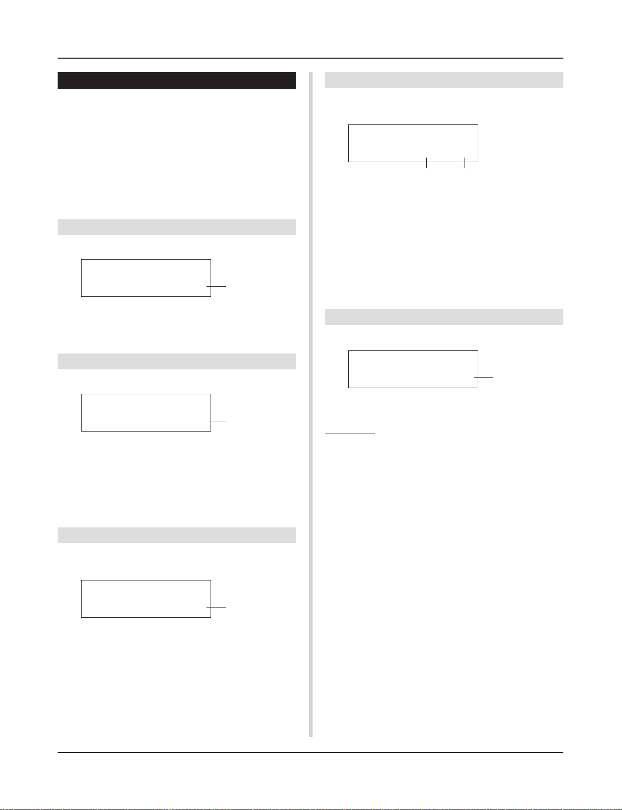
Drum Kit Voice Edit Mode
5. Drum Kit Common Parameters
This function sets the common settings for the entire drum kit.
The Drum Kit Common Parameters are divided into the following
5 pages.
5-1. Volume …………………………………………………… 23
5-2. Drum Reverb Send…………………………………… 23
5-3. Hi-Hat Sensitivity ……………………………………… 23
5-4. Song Select …………………………………………….. 23
5-5. Drum Kit Name ………………………………………… 23
5-1. Volume
Sets the overall volume for the drum voice.
KIT Common
Volume= 127
q Volume
[Range] 0-127
5-2. Drum Reverb Send
Sets the overall reverb send level of the drum voice.
q
5-4. Song Select
This parameter allows you to switch the main song q at the same
time the drum kit is switched.
KIT Common
SongSel=110ƒ=120
q w
q Song Select (Song Number)
[Range] —, 1-127
Assign the song number to select the song for playback. The song
will not be switched if the setting is set to “—”.
w q (Tempo)
[Range] —, 30-300
Assign the tempo that will be used. If “—” is set, the tempo will
not change .
5-5. Drum Kit Name
Changes the drum kit name that is currently selected for editing.
KIT Common
Kit=Acoustic Kit
q
KIT Common
DrumRevSend 40
q DrumRevSend (Drum Reverb Send Level)
[Range] 0-127
The actual reverb send level will be determined by multiplying the
reverb send level set in [2-2. Reverb Send] (P. 19) with the value
set here.
5-3. Hi-Hat Sensitivity
Sets the foot controller sensitivity connected to HI-HAT CONTROL jack on the rear panel.
q
KIT Common
HH Sensitivty=32
q HH Sensitivty
[Range] 0-63
Larger values provide higher sensitivity.
q
q Kit (Drum Kit Name)
Procedure
1.
In the display shown above, use the [SEL<]/[SEL>] buttons to move the cursor to the character you want to
change.
2.
Use the [VALUE–]/[VALUE+] buttons to select the alphabet, number or symbol.
3.
Repeat steps 1 and 2 above to create the Drum Kit Name
using a maximum of 12 characters.
● The available characters to choose from are (in order):
space
!»#$%&'()*+,-./0123456789:;<=>?@
ABCDEFGHIJKLMNOPQRSTUVWXYZ[\]^_`
abcdefghijklmnopqrstuvwxyz{|}ßå
23
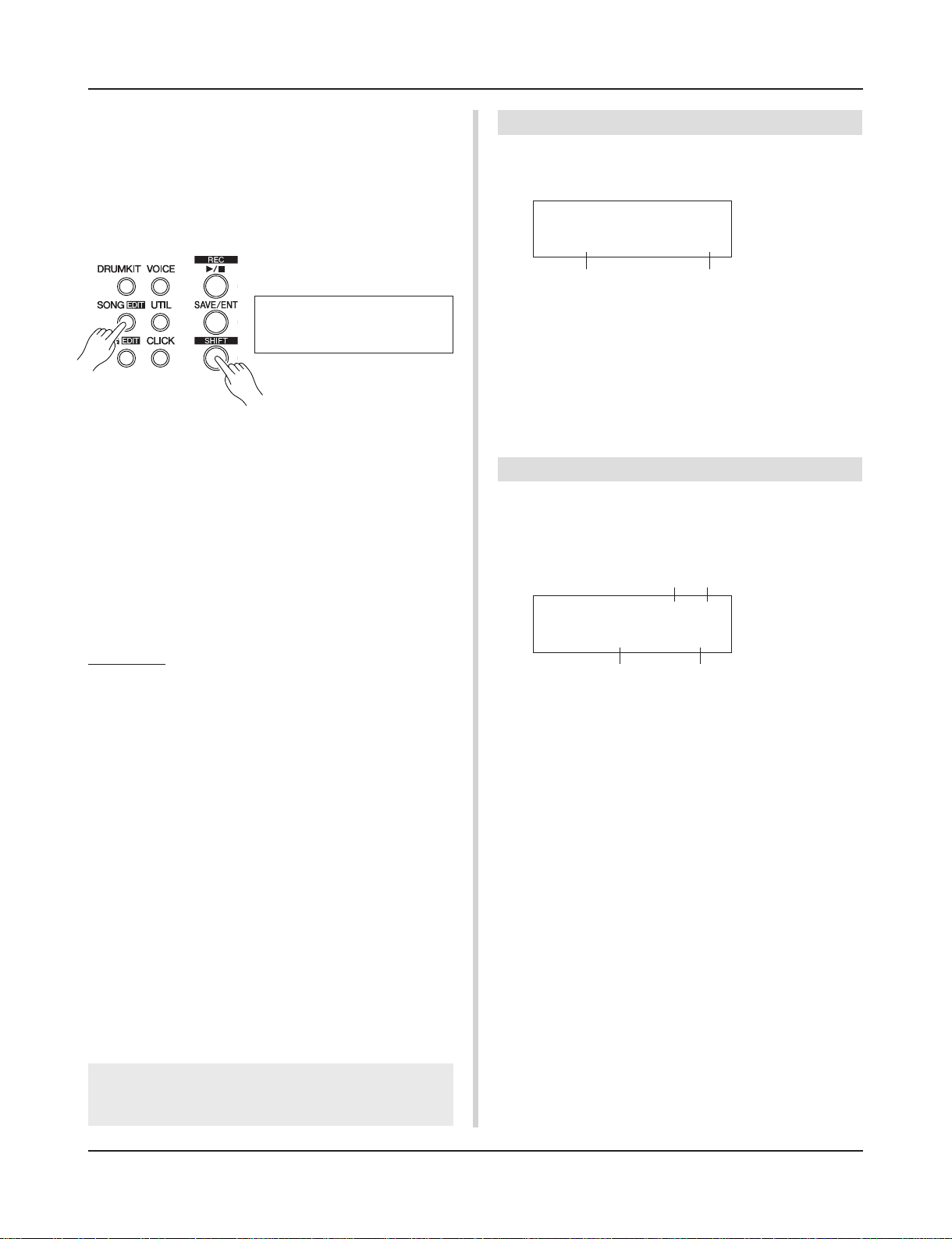
Song Edit Mode
This function edits the User Song (No. 97-128) that is
currently selected.
■ Entering the Song Edit Mode
Hold the [SHIFT] button and press the [SONG] button on the front
panel.
Once the Song Edit Mode is entered, the main page (Tempo, Repeat Playback) shown below will be displayed.
SONG
ƒ=120 Repeat=off
■ What’s in the Song Edit Mode
The Song Edit Mode is divided into the following 9 pages.
1. Tempo, Repeat Playback ………………………………. 24
2. Program Change, Bank Select ………………………. 24
3. Volume, Pan ………………………………………………… 25
4. Song Copy ………………………………………………….. 25
5. Quantize ……………………………………………………… 25
6. Clear Track ………………………………………………….. 26
7. Merge Track ………………………………………………… 26
8. Clear Song ………………………………………………….. 26
9. Song Name …………………………………………………. 26
Procedure
1.
Press the [SONG] button to enter the Song & Tempo display, then select the User Song (No. 97-128) you want to
edit.
2.
Hold the [SHIFT] button and press the [SONG] button to
enter the Song Edit mode.
* If the [SHIFT]+[SONG] buttons are pressed when a preset
song is already selected, “CAN’T EDIT PRESET SONG” will
appear and the Song Edit Mode cannot be entered.
3.
Use the [PAGEs]/[PAGEt] buttons to display the page
you want to edit.
* If the Utility Mode’s [2-4. Jump To Recent Page] (P. 29) pa-
rameter is set to “on”, The DTXPRESS II will display the page
last edited when entering the Song Edit mode.
4.
Use the [SEL<]/[SEL>] buttons to move the cursor to
the parameter you want to edit. The parameter will flash.
* If there is only one parameter, it is not necessary to move the
cursor.
1. Tempo, Repeat Playback
This function changes the tempo (rewrites the tempo information
in the song’s header) and sets the repeat playback of the user song.
SONG
ƒ=120 Repeat=off
q w
q q (Tempo)
[Range] 30-300
w Repeat (Repeat Playback)
[Range] off, on
If this is set to “on”, the user song will repeat playback.
If this is set to “off”, the user song will play normally.
2. Program Change, Bank Select
This function changes the voices that will be used for each MIDI
channel in the user song (rewrites the voice information in the
song’s header). This program change will be transmitted when a
song is selected and when song playback is stopped.
wq
SONG Ch 1=off
PCNo=— V=——
e r
q MIDI Channel
[Range] Ch1-Ch16
w Program Change Transmit On/Off
on: Transmits.
off:Does not transmit.
e PCNo (Program Change Number)
[Range] 1-128
r V (Bank Select)
[Range] meldy, drumV
Sets the bank that will be switched.
meldy: Transmits the melody voice program change (MSB=0).
drumV: Transmits the drum voice program change (MSB=127).
5.
Use the [VALUE–]/[VALUE+] buttons to set the
parameter’s value or ON/OFF setting.
Any settings made in the Song Edit Mode will directly
change the settings in the memory of the DTXPRESS II. It
is not necessary to use the Store Operation.
24
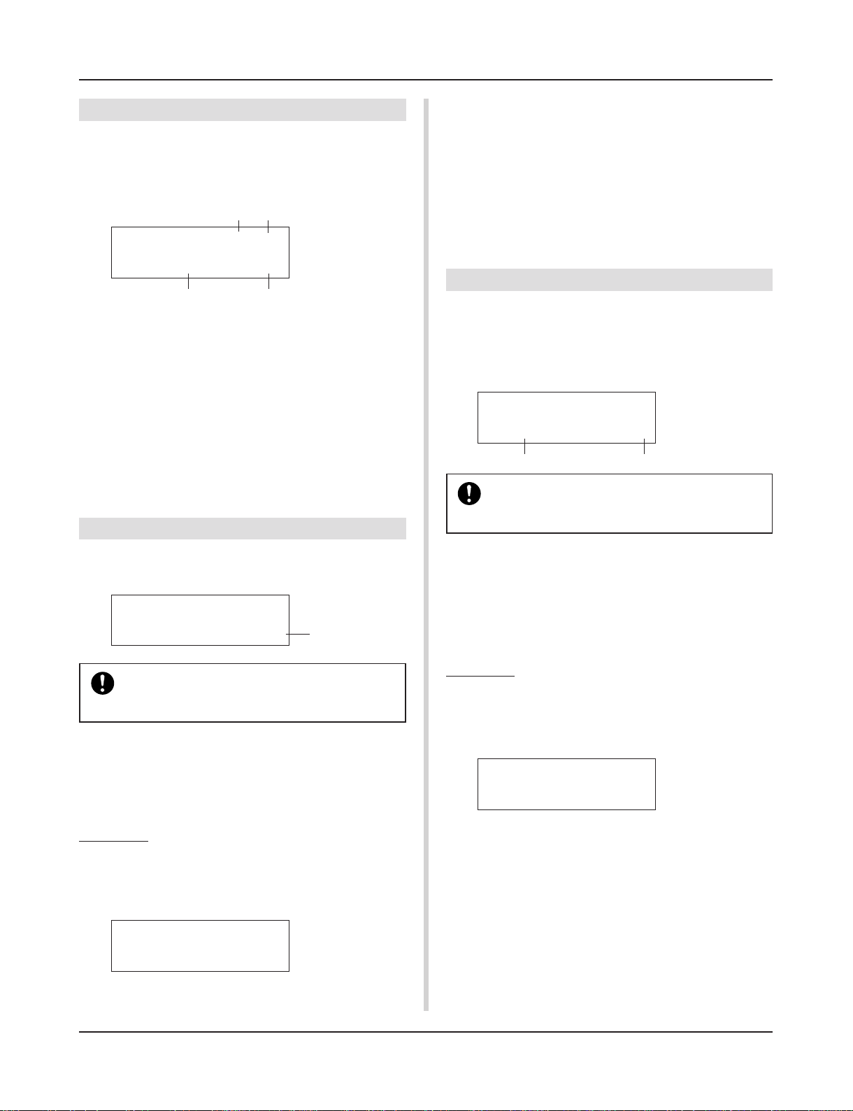
Song Edit Mode
3. Volume, Pan
This function changes the volume and pan settings for each MIDI
channel in the user song (rewrites the Voice information in the
song’s header). This control change will be transmitted when a
song is selected and when song playback is stopped.
q
w
SONG Ch 1=off
Vol= — Pan=—
e r
q MIDI Channel
[Range] Ch1-Ch16
w Control Change transmit On/Off
on: Transmits.
off: Does not transmit.
e Vol (Volume)
[Range] 0-127
r Pan
[Range] 0-127
4. Song Copy
* Press the [VALUE-] button to cancel the copy operation.
* During song playback, the copy operation cannot be carried out.
“ERROR SEQ is Running” will appear. Stop the song and try
the copy operation again.
* If memory is insufficient when in the copy operation, “ERROR
Memory Full” will appear. Clear any unnecessary user songs
and try the copy operation again.
When the copy operation is complete, “Complete!” will appear.
5. Quantize
This function quantizes each track q of the user song to the accuracy w defined here.
quantize: When the timing of the sequence data that was recorded
is inaccurate, this function is used to correct the timing. The
accuracy for correcting can be assigned using note lengths.
SONG Quantize
TR=1 Value= ƒ
q w
When the Quantize operation is carried out, all data
in the assigned track of the currently selected user
song will be replaced.
This function copies the assigned song q to the user song that is
currently selected.
SONG Copy
from= 1HighRise
When the Song Copy operation is carried out, all
data in the User Song that is currently selected will
be replaced with data of the copy source.
q from (Copy Source)
[Range] 1-127
Sets the song that is the copy source. The song number and name
will be displayed. A preset song or a user song can be assigned.
Procedure
1.
Assign the Copy Source Song on the display shown
above, press the [SAVE/ENT] button. The following display will appear asking for confirmation before the copy
operation is carried out.
q
CopySONG From 1
Are you sure ?
2.
Press the [SAVE/ENT] or [VALUE+] button, the copy
operation will be carried out.
q TR (Specified Track)
Assigns the track (“1” or “2”) to be quantized.
w Value (Quantize Accuracy)
[Range] ƒ quarter note, ƒ3 quarter note (triplet),
© eighth note, ©3 eighth note (triplet),
˙ sixteenth note, ˙3 sixteenth note (triplet)
Procedure
1.
Set the track and the quantize accuracy on the display
shown above, press the [SAVE/ENT] button.
The following display will appear asking for confirmation
before the quantize operation is carried out.
Quantize Tri ƒ
Are you sure ?
2.
Press the [SAVE/ENT] or [VALUE+] button, the quantize
operation will be carried out.
* Press the [VALUE-] button to cancel the quantize operation.
* During song playback, the quantize operation cannot be car-
ried out. “ERROR SEQ is Running” will appear. Stop the
song and try the quantize operation again.
* If memory is insufficient when in the quantize operation, “ER-
ROR Memory Full” will appear. Clear any unnecessary user
songs and try the quantize operation again.
When the quantize operation is complete, “Complete!” will appear.
25
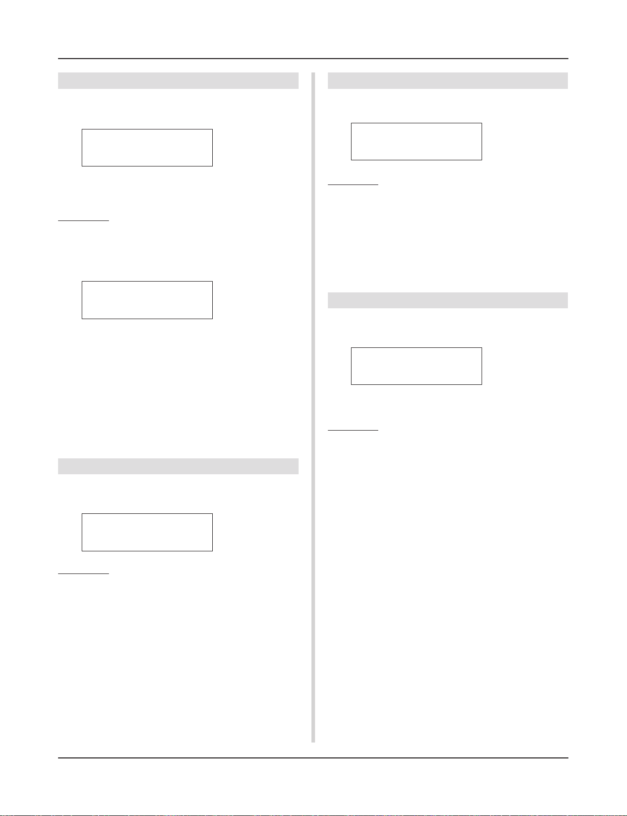
Song Edit Mode
6. Clear Track
This function clears all data in the assigned track q in the user
song.
SONG Clear Track
Track=1
q TR (Specified Track)
Assigns the track (“1” or “2”) to be cleared.
Procedure
1.
Assign the track you want to clear on the display shown
above, press the [SAVE/ENT] button.
The following display will appear asking for confirmation
before the clear track operation is carried out.
Clear Track 1
Are you sure ?
2.
Press the [SAVE/ENT] or [VALUE+] button, the clear track
operation will be carried out.
* Press the [VALUE–] button to cancel the clear track opera-
tion.
* During song playback, the clear track operation cannot be
carried out. “ERROR SEQ is Running” will appear. Stop the
song and try the clear track operation again.
When the Clear Track operation is complete, “Complete!” will
appear.
7. Merge Track
This function merges (mixes) the sequence data in tracks 1 and 2
of the user song to track 1.
SONG Merge Track
Are you sure ?
Procedure
1.
Press the [SAVE/ENT] button on the display shown
above, the merge operation will be carried out.
When the Merge Track operation is complete, “Com-
plete!” will appear.
* If memory is insufficient when in the merge operation, “ER-
ROR Memory Full” will appear. Clear any unnecessary user
songs and try the merge operation again.
* During song playback, the merge operation cannot be car-
ried out. “ERROR SEQ is Running” will appear. Stop the
song and try the merge operation again.
8. Clear Song
This function clears the sequence data in tracks 1 and 2 of the user
song.
SONG Clear Song
Are you sure ?
Procedure
1.
Press the [SAVE/ENT] button on the display shown
above, the clear song operation will be carried out.
When the Clear Song operation is complete, “Com-
plete!” will appear.
* During song playback, the clear song operation cannot be
carried out. “ERROR SEQ is Running” will appear. Stop the
song and try the clear song operation again.
9. Song Name
This function changes the user song name that is currently selected
(for editing).
SONG
SngName=no name
q SngName (Song Name)
Procedure
1.
Use the [SEL<]/[SEL>] buttons to move the cursor to
the character you want to change on the display shown
above.
2.
Use the [VALUE–]/[VALUE+] buttons to select the alphabet, number or symbol.
3.
Repeat steps 1 and 2 above to create the User Song
Name using a maximum of 8 characters.
● The available characters to choose from are (in order):
space
!»#$%&'()*+,-./0123456789:;<=>?@
ABCDEFGHIJKLMNOPQRSTUVWXYZ[\]^_`
abcdefghijklmnopqrstuvwxyz{|}ßå
26
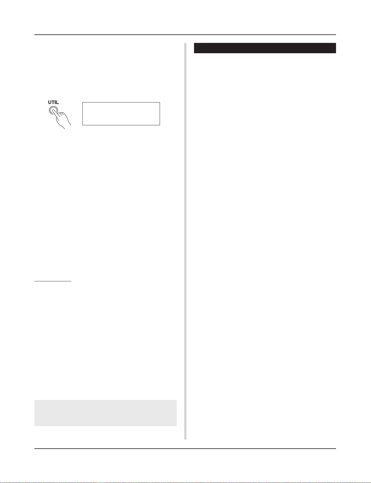
Utility Mode
This mode sets general parameters for the DTXPRESS
II system and MIDI.
■ Enter the Utility Mode
Press the [UTIL] button on the front panel.
Once the Utility Mode is entered, the TG Group main page (Equalizer) shown below will be displayed.
UT TG MASTER
EQ Lo=+ 6 Hi=+ 0
■ What’s in the Utility Mode
The Utility Mode is divided into the 5 sub-groups listed below.
1. TG (Tone Generator) Group …………. (mP. 28)
Contains various settings that apply to the
DTXPRESS II’s tone generator.
2. SYSTEM Group …………………………… (mP. 29)
Contains various settings that affect the entire
DTXPRESS II system.
3. MIDI Group …………………………………. (mP. 30)
Contains various settings for the DTXPRESS II’s
MIDI and TO HOST functions.
4. SEQ (Sequencer) Group ……………… (mP. 33)
Contains various settings that apply to the
DTXPRESS II’s sequencer (song).
5. MAP (Drum Map) Group ………………. (mP. 35)
Used to edit the User Drum Map.
How to set…
1.
Press the [UTIL] button to enter the Utility Mode.
2.
Select the sub-mode.
• Press the [UTIL] button to move to the next sub group’s main
page.
• Use the [PAGE▲], [PAGE▼] buttons to move to page by page
within the selected sub group. You can use these buttons to
navigate through all of the pages (from the first System Group
main page to the last MAP Group page).
3.
Use the [SEL<], [SEL>] buttons to move the cursor to
the setting you want to change. The value will flash.
* If there is only one parameter, it is not necessary to move the
cursor.
4.
Use the [VALUE–] and [VALUE+] buttons to set the
parameter’s value or ON/OFF setting.
Any settings made in the Utility Mode will directly change
the memory settings of the DTXPRESS II. There is no
store function in this mode.
Utility Mode Function List
Page
1. TG (Tone Generator) Group ………………………………. 28
1-1. Equalizer (EQ) …………………………………………. 28
1-2. Mute ………………………………………………………. 28
1-3. Tuning…………………………………………………….. 28
1-4. Volume …………………………………………………… 28
1-5. Reverb Bypass ………………………………………… 28
2. SYSTEM Group………………………………………………… 29
2-1. Learn Mode …………………………………………….. 29
2-2. Trigger Bypass…………………………………………. 29
2-3. Volume Mode ………………………………………….. 29
2-4. Jump to Recent Page ……………………………….. 29
2-5. Hi-Hat Offset ……………………………………………. 30
2-6. Factory Set ……………………………………………… 30
3. MIDI Group ………………………………………………………. 30
3-1. Bulk Dump ………………………………………………. 30
3-2. Channel 10 Program Change/
Channel Event Receive …………………………….. 31
3-3. Receive Program Change/
System Exclusive Messages ……………………… 31
3-4. Program Change Table ……………………………… 32
3-5. MIDI Mode ………………………………………………. 32
3-6. Device Number, Local Control……………………. 32
3-7. MIDI Merge ……………………………………………… 32
3-8. Dump Interval ………………………………………….. 33
3-9. Send Hi-Hat Control …………………………………. 33
3-10. Host Thru Port …………………………………………. 33
4. Sequencer Group …………………………………………….. 33
4-1. Click Voice ………………………………………………. 33
4-2. Click Tune ……………………………………………….. 34
4-3. Click Note Number …………………………………… 34
4-4. MIDI Control ……………………………………………. 34
4-5. Count Switch …………………………………………… 34
4-6. Sync Mode ……………………………………………… 34
4-7. Use Tempo ……………………………………………… 35
4-8. Click Mode ………………………………………………. 35
5. MAP (Drum Map) Group……………………………………. 35
5-1. Voice………………………………………………………. 35
5-2. Volume, Pan ……………………………………………. 36
5-3. Tuning…………………………………………………….. 36
5-4. Layer Balance………………………………………….. 36
5-5. Decay, Cutoff Frequency …………………………… 36
5-6. Reverb Send……………………………………………. 36
5-7. Alternate Group, Key Assign Mode …………….. 37
5-8. Key Off Enable ………………………………………… 37
5-9. Map Copy ……………………………………………….. 37
27
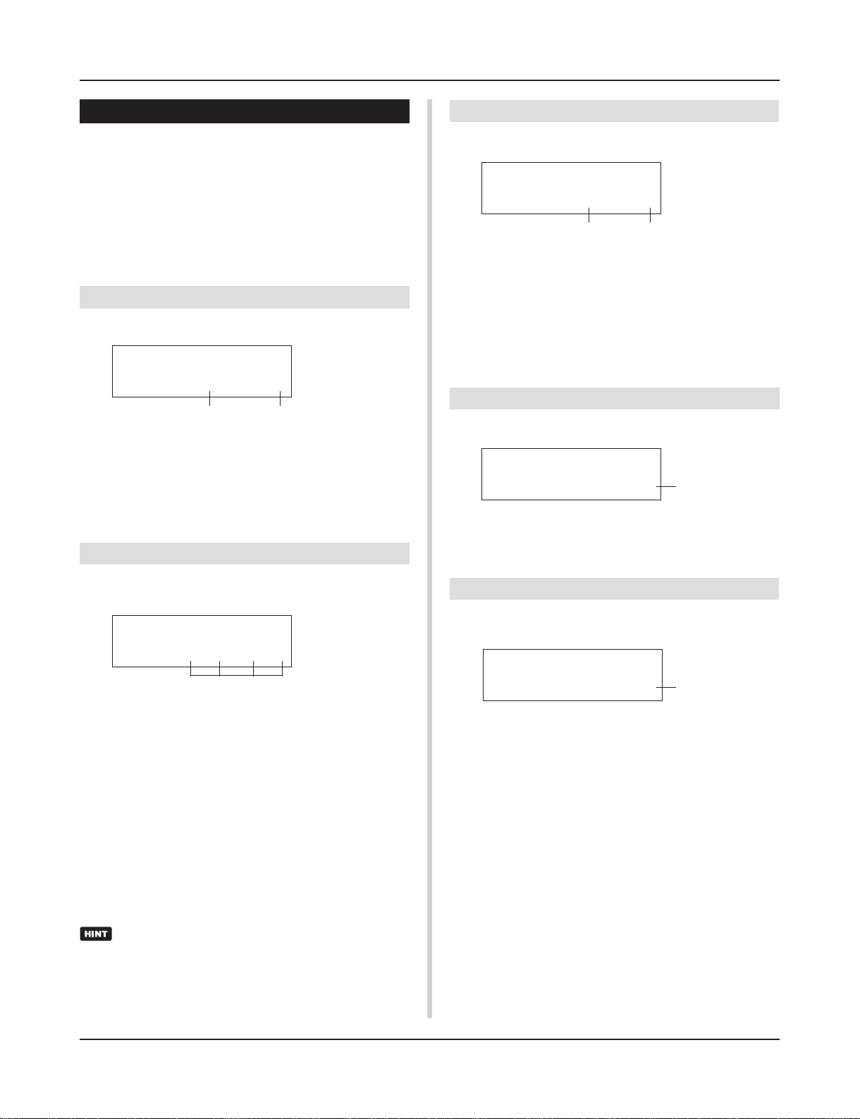
Utility Mode
1. TG (Tone Generator) Group
This sub-mode contains settings for the DTXPRESS II’s tone generator. This group is divided into the following 5 pages.
1-1. Equalizer (EQ) …………………………………………. 28
1-2. Mute ………………………………………………………. 28
1-3. Tuning…………………………………………………….. 28
1-4. Volume …………………………………………………… 28
1-5. Reverb Bypass ………………………………………… 28
1-1. Equalizer (EQ)
Sets the Master Equalizer (2-band shelving type).
UT TG MASTER
EQ Lo=+ 6iHi=+ 0
q
q EQ Lo (Low Gain)
[Range] +0 to +12 (dB)
w EQ Hi (High Gain)
[Range] +0 to +12 (dB)
1-2. Mute
w
1-3. Tuning
This function sets the master tuning of the tone generator.
UT TG MASTER
Tune C= 0 F= 0
q
q Tune C (Tune Coarse)
[Range] –24 to 0 to +24
Tuning can be set in increments of a half step.
w Tune F (Tune Fine)
[Range] –64 to 0 to +63
Tuning can be set in increments of about 1.17 cents.
1-4. Volume
This function sets the overall volume level of the tone generator.
w
UT TG MASTER
Volume= 110
q Volume
[Range] 0-127
q
This setting can be used to mute four types of instruments, K (kick),
S (snare), C (cymbal), and M (others).
UT TG MASTER
MuteK=mS=®C=®M=®
q
q Drum Mute
[Range] m (mute; Does not produce sound), ® (Produces sound)
* Drum voice types
Drum voices are divided into many groups (categories) in accordance with the type of sound i.e. kick, snare, etc. For more
information on Drum Voice categories, refer to the [Drum Voice
List] (P. 38).
Drum Voice Category Mute Classification
K, k K (kick)
S, s S (snare)
C, H C (cymbal)
T, t, P, E, e, L, m M (others)
Since drum voices for pads (triggers) are not muted you
can, for example, mute the snare voice of a song and practice the snare part along with song playback (the snare
voice is delivered when the pad is hit).
1-5. Reverb Bypass
This function decides whether to bypass the system effect’s reverb
or not.
UT TG MASTER
ReverbBypass=off
q ReverbBypass (Reverb Bypass)
off: Does not bypass (functions). Normal operation.
on: Bypasses. Reverb will not be applied to the voice.
q
28
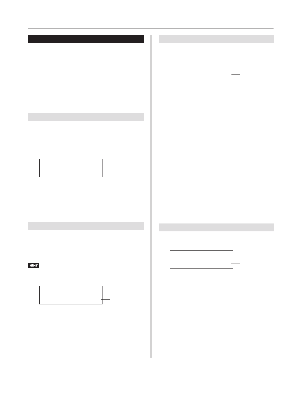
Utility Mode
2. SYSTEM Group
This sub-mode contains settings that relate to the overall
DTXPRESS II system. The group is divided into the following 6
pages.
2-1. Learn Mode …………………………………………….. 29
2-2. Trigger Bypass…………………………………………. 29
2-3. Volume Mode ………………………………………….. 29
2-4. Jump to Recent Page ……………………………….. 29
2-5. Hi-Hat Offset ……………………………………………. 30
2-6. Factory Set ……………………………………………… 30
2-1. Learn Mode
This function allows selection of the pad (trigger input) you want
to edit by hitting the pad when you are editing in the Trigger Setup
Edit mode or Drum Kit Edit mode. Also, MIDI key on input from
the MIDI IN/TO HOST jack can be used to appoint the MIDI note
number in the Utility mode’s User Map Setting.
UT SYSTEM
LearnMode=allwys
q LearnMode
allwys:Always appoints according to pad/key on input.
shift: Hitting a pad or key on input while holding the [SHIFT]
button selects the pad or note.
none: Can’t appoint according to pad/key on input.
q
2-3. Volume Mode
Sets the ACCOMP. VOL knob and CLICK VOL knob on the front
panel.
UT SYSTEM
VolMode=practice
q VolMode (Volume Mode)
• practice : When set to the practice mode.
[ACCOMP. VOL]
Using the [ACCOMP. VOL] knob as is will adjust the volume of
the song accompaniment.
Holding the [SHIFT] button while turning the knob will adjust the
snare drum volume.
[CLICK VOL]
Using the [CLICK VOL] knob as is will adjust the volume of the
metronome click.
Holding the [SHIFT] button while turning the knob will adjust the
bass drum volume.
• live: When set to the Live mode.
[ACCOMP. VOL]
Using the [ACCOMP. VOL] knob as is will adjust the snare drum
volume.
Holding the [SHIFT] button while turning the knob will adjust the
cymbal volume.
[CLICK VOL]
Using the CLICK VOL knob as is will adjust the bass drum volume.
Holding the [SHIFT] button while turning the knob will adjust the
volume of the drum’s other drum instruments.
q
2-2. Trigger Bypass
This function prohibits reception of pad signals from pads (the hihat controller too) connected to the DTXPRESS II. You will not
be able to produce voices or transmit MIDI data. The sequencer
and tone generator will function normally.
Use this function when you are setting your drum kit with
trigger pickup devices, or when you do not want to accidentally make a sound during song playback.
UT SYSTEM
Trig Bypass=ioff
q Trig Bypass
off: Bypasses the trigger (does not receive).
on: The trigger functions normally (receives trigger).
q
2-4. Jump to Recent Page
This function lets you display the page last selected in the previous edit of the Trigger Setup Edit mode and Drum Kit Edit mode.
UT SYSTEM
JumpRecentPg=off
q JumpRecentPg (Jump to Recent Page)
on: The display page last selected in the previous edit will ap-
pear when you enter the Trigger Setup Edit, Drum Kit Edit,
Utility and Song Edit modes.
off: The main page of each mode will be displayed.
q
29
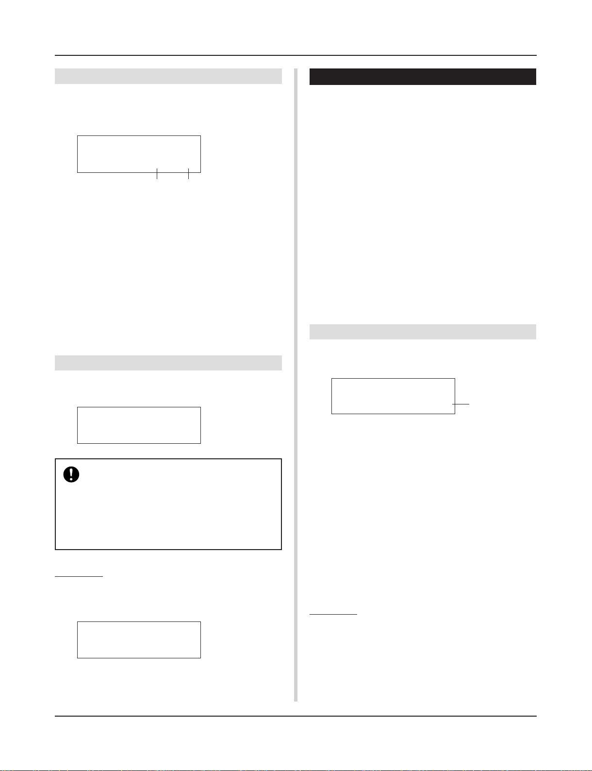
Utility Mode
2-5. Hi-Hat Offset
This sets the value of the data sent by a foot controller connected
to the HI HAT CONTROL jack on the rear panel. Set a + (plus) or
– (minus) level.
UT SYSTEM
HH OffS= 0T= 32
q w
q HH OFFS (Hi-Hat Offset)
When a low data value is received from the foot controller, the
voice will sound sooner. So, slightly pressing the foot controller
will result in the voice sounding. In the case of the hi-hat controller, delicate adjustment of the controller’s “closed” point is possible.
w T (Foot Splash Detect Time)
Sets the detect time for the foot splash. Large values make foot
splashes easier to produce.
* Values too large will result in splashes being produced under
normal hi-hat use.
2-6. Factory Set
3. MIDI Group
This sub-mode contains functions and settings for the MIDI and
TO HOST jacks of the DTXPRESS II. This group is divided into
the following 10 pages.
3-1. Bulk Dump ………………………………………………. 30
3-2. Channel 10 Program Change/
Channel Event Receive …………………………….. 31
3-3. Receive Program Change/
System Exclusive Messages ……………………… 31
3-4. Program Change Table ……………………………… 32
3-5. MIDI Mode ………………………………………………. 32
3-6. Device Number, Local Control……………………. 32
3-7. MIDI Merge ……………………………………………… 32
3-8. Dump Interval ………………………………………….. 33
3-9. Send Hi-Hat Control …………………………………. 33
3-10. Host Thru Port …………………………………………. 33
* Please refer to the [MIDI Data Format] (P. 50) section for more
information related to MIDI.
3-1. Bulk Dump
With the Bulk Dump operation, data stored in the DTXPRESS II
can be transmitted via the MIDI OUT or TO HOST jack.
This function replaces all internal settings in the DTXPRESS II to
their factory-set condition.
UT SYSTEM
Factory Set
The Factory Set function will replace all internal settings in the DTXPRESS II to their factory-set condition. Take care so as not to loose important data.
Make sure any settings and user songs you want to
keep have been saved to an external device such as
the Yamaha MIDI Data Filer MDF3, etc. (m[3-1.
Bulk Dump] (P. 30)
Procedure
1.
Enter the display shown above, press the [SAVE/ENT]
button. The following display will appear asking for confirmation before the Factory Set operation is carried out.
All data will be
lost.AreYouSure?
2.
Once again, press the [SAVE/ENT] button to proceed
with the operation.
UT MIDI BULKDUMP
Fmt= all data
q Fmt (Bulk Dump Format)
Selects the type of data to be transmitted with the Bulk Dump
operation.
all data : All the data in the DTXPRESS II
system data : Data set in the Utility mode (except User
Map).
user map : User Map data.
one drumkit : Data for the currently selected Drum Kit.
all drumkit : All User Drum Kit Data.
one trigger : Data for the currently selected Trigger Setup.
all trigger : All User Trigger Setup data
one song : Data for the currently selected User Song.
all song : All User Song data.
Procedure
1.
After reading the [Connecting a MIDI Device] (Basic
Guide : P. 12) or the [Connecting a Computer] (Basic
Guide : P. 26) section, connect the external MIDI device
or computer to the MIDI OUT or TO HOST jack on the
DTXPRESS II. Set the HOST SELECT switch.
q
30
Loading…

DRUM TRIGGER MODULE
V930810 Printed in Japan
DTX Information
http://www.yamaha.co.jp/english/product/drum/dtx/index.html
Owner’s Manual / Basic Guide
Mode d’emploi / Guide de référence rapide
Bedienungsanleitung / Basishandbuch
Manual de instrucciones / Guía básica
Manuale dell’utente / Guida di base
Gebruikershandleiding / Basisgids
English
Français
Deutsch
Español
Italiano
Nederlandse
DR
UM TRIGGER
MODULE
02.4.27, 4:42 PM
Page 1
Yamaha DTXPRESS II Musical Instrument PDF User Guides and Manuals for Free Download: Found (2) Manuals for Yamaha DTXPRESS II Device Model (Owner’s Manual)
The Yamaha DTXPRESS II is a powerful electronic drum kit that caters to drummers of all skill levels. Integrated with advanced technology, this kit presents a plethora of features designed to enhance practice and performance. Known for its user-friendly interface, high-quality sound samples, and customizable settings, the DTXPRESS II stands out as a leading choice in the realm of electronic percussion.
One of the key attributes of the Yamaha DTXPRESS II is its quality sound engine. With over 100 preset drum kits, drummers can simulate a variety of genres and playing styles. The realistic drum sounds are achieved through advanced sampling techniques, ensuring that the nuances of acoustic drums are well represented. Users have access to a diverse array of instruments that include not just drums but also cymbals, percussion, and special effects.
Additionally, the DTXPRESS II offers impressive MIDI capabilities. This allows drummers to connect the kit to DAWs (Digital Audio Workstations) and other musical equipment seamlessly. With MIDI integration, musicians can use the DTXPRESS II for recording, composing, and layering their tracks in a digital format. This feature expands the versatility of the instrument, making it suitable for studio environments as well as live performances.
Another outstanding feature of the Yamaha DTXPRESS II is its practice functionality. The kit comes with built-in metronome and practice exercises which are invaluable for both beginners and experienced drummers. These tools help users develop their timing and rhythm skills, making practice sessions more effective and enjoyable. Furthermore, it includes training modes that are designed to improve performance through structured learning.
When it comes to its build quality, the Yamaha DTXPRESS II does not fall short. The pads are responsive and provide an excellent feel, closely mirroring their acoustic counterparts. The durable construction ensures that the kit can withstand rigorous practice sessions as well as the demands of live performances. This reliability is a significant advantage for drummers who play frequently and need equipment that can keep pace.
However, the DTXPRESS II is not without its downsides. Some drummers have pointed out that while the kit is excellent for practice and recording, it may require additional investments when it comes to expansion and accessories for live usage. For instance, additional pads or triggers can be beneficial for those looking to enhance their setup. Additionally, the user interface, although user-friendly, may take some time for new users to get accustomed to.
In summary, the Yamaha DTXPRESS II is an exceptional electronic drum kit that offers extensive features suitable for a range of players. Whether you are a beginner looking to develop your skills or a seasoned professional seeking a versatile tool for performance and recording, the DTXPRESS II meets these needs effectively. Its combinations of quality sounds, MIDI capabilities, and robust build make it a strong contender in the electronic drum market.
- Pros: High-quality sound engine, versatile MIDI capabilities, excellent practice features, durable build.
- Cons: May require additional accessories for live performances, learning curve for new users.
In conclusion, investing in the Yamaha DTXPRESS II is a decision that many drummers won’t regret. The blend of quality, versatility, and user-friendly features solidifies its reputation as a top-tier electronic drum kit.
- Addeddate
- 2021-06-25 15:03:47
- Identifier
- manualzilla-id-7258737
- Identifier-ark
- ark:/13960/t7gr8nh65
- Ocr
- tesseract 5.0.0-alpha-20201231-10-g1236
- Ocr_autonomous
- true
- Ocr_detected_lang
- la
- Ocr_detected_lang_conf
- 1.0000
- Ocr_detected_script
- Latin
- Ocr_detected_script_conf
- 0.9963
- Ocr_module_version
- 0.0.13
- Ocr_parameters
- -l fra+nld+deu+spa+ita+eng+ltz+oci+Latin
- Page_number_confidence
- 75.41
comment
Reviews
There are no reviews yet. Be the first one to
write a review.
144
Views
DOWNLOAD OPTIONS
Temporarily Unavailable
DAISY
For users with print-disabilities
Temporarily Unavailable
EPUB
Uploaded by
chris85
on