
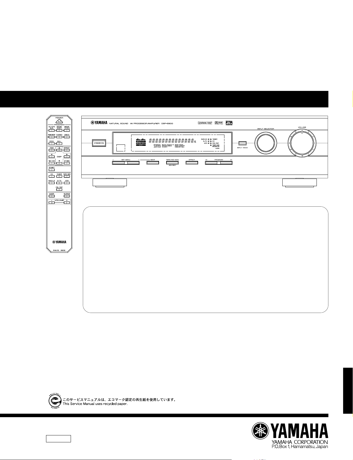
DSP-E800
AV PROCESSOR/AMPLIFIER
DSP-E800
SERVICE MANUAL
IMPORTANT NOTICE
This manual has been provided for the use of authorized YAMAHA Retailers and their service personnel.
It has been assumed that basic service procedures inherant to the industry, and more specifically YAMAHA Products, are already known and
understood by the users, and have therefore not been restated.
WARNING: Failure to follow appropriate service and safety procedures when servicing this product may result in personal injury,
IMPORTANT: The presentation or sale of this manual to any individual or firm does not constitute authorization, certification or
The data provided is believed to be accurate and applicable to the unit(s) indicated on the cover. The research, engineering, and service
departments of YAMAHA are continually striving to improve YAMAHA products. Modifications are, therefore, inevitable and specifications
are subject to change without notice or obligation to retrofit. Should any discrepancy appear to exist, please contact the distributor’s Service
Division.
WARNING: Static discharges can destroy expensive components. Discharge any static electricity your body may have accumulated by
IMPORTANT: Turn the unit OFF during disassembly and parts replacement. Recheck all work before you apply power to the unit.
destruction of expensive components and failure of the product to perform as specified. For these reasons, we advise all
YAMAHA product owners that all service required should be performed by an authorized YAMAHA Retailer or the
appointed service representative.
recognition of any applicable technical capabilities, or establish a principle-agent relationship of any form.
grounding yourself to the ground buss in the unit (heavy gauge black wires connect to this buss).
■ CONTENTS
TO SERVICE PERSONNEL …………………………………… 1
REAR PANELS …………………………………………………….. 1
SPECIFICATIONS …………………………………………………. 2
INTERNAL VIEW ………………………………………………….. 3
DISASSEMBLY PROCEDURES ……………………….. 3—4
ADJUSTMENTS ……………………………………………………. 5
SELF DIAGNOSIS FUNCTION………………………… 6—17
FACTORY PRESET …………………………………………….. 18
IC DATA ……………………………………………………… 19—27
DISPLAY DATA ………………………………………………….. 28
PIN CONNECTION DIAGRAM ……………………………… 29
BLOCK DIAGRAM ……………………………………….. 30—31
PRINTED CIRCUIT BOARD ………………………….. 32—41
SCHEMATIC DIAGRAM ……………………………….. 42—47
PARTS LIST ………………………………………………… 48—59
REMOTE CONTROL TRANSMITTER……………………. 60
DSP-E800
100719

DSP-E800
■ TO SERVICE PERSONNEL
Critical Components Information
Components having special characteristics are marked Z
and must be replaced with parts having specifications equal
to those originally installed.
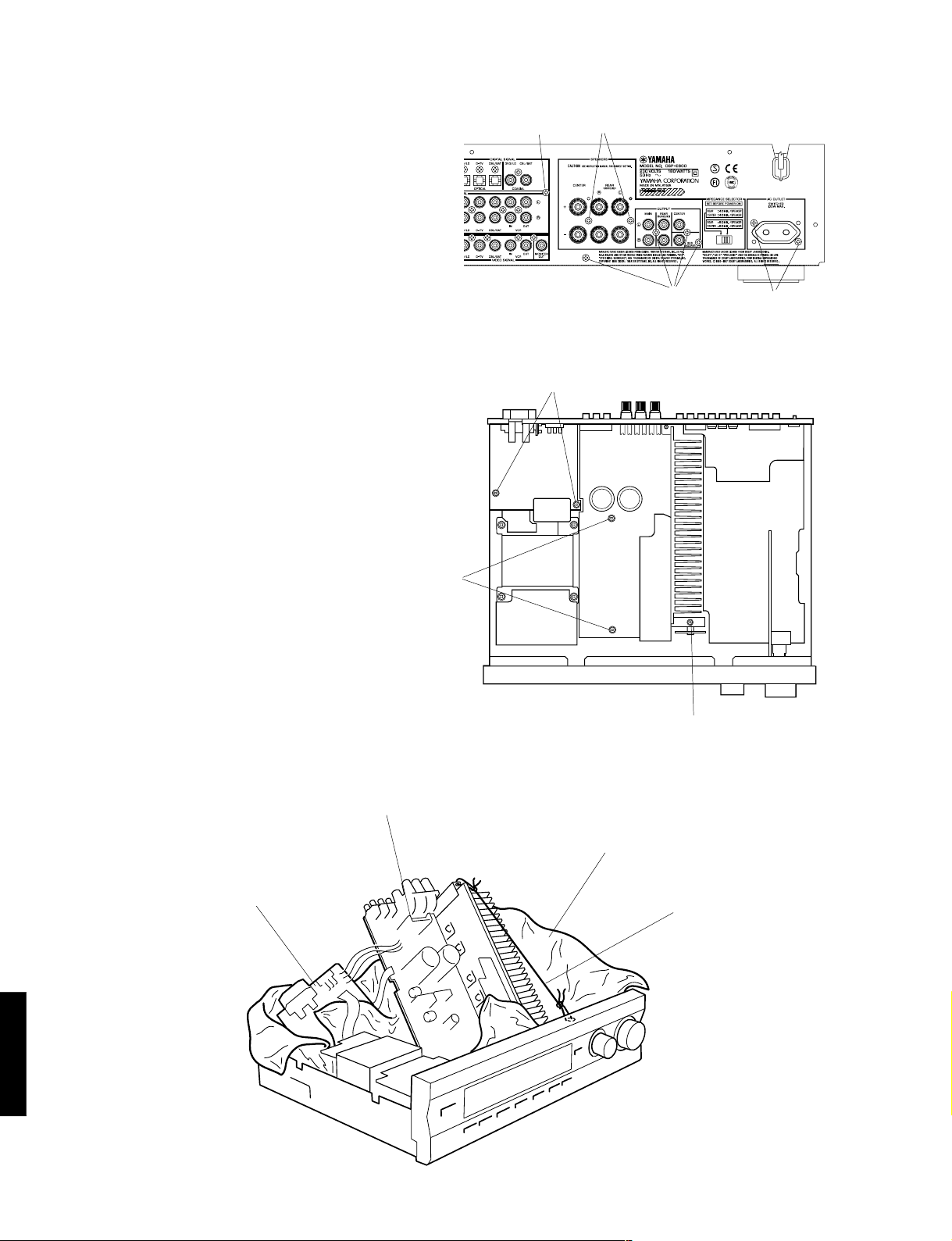
■ REAR PANELS
▼ B model
WALL
OUTLET
EQUIPMENT
UNDER TEST
INSULATING
TABLE
AC LEAKAGE
TESTER OR
EQUIVALENT
▼ G model
WARNING
Do not change the IMPEDANCE SELECTOR switch
setting while the power to this unit is on, otherwise
this unit may be damaged.
IMPEDANCE SELECTOR
DSP-E800
1

■ SPECIFICATIONS
DSP-E800
■ AUDIO SECTION
Minimum RMS Output Power per Channel
CENTER
20Hz to 20kHz, 0.06% THD, 8Ω 70W
1kHz, 0.09% THD, 8Ω 80W
REAR
20Hz to 20kHz, 0.06% THD, 8Ω 70W+70W
1kHz, 0.09% THD, 8Ω 80W+80W
Dynamic Power per Channel (IHF)
REAR, 8Ω 90W+90W
REAR, 6Ω 110W+110W
REAR, 4Ω 135W+135W
REAR, 2Ω 160W+160W
DIN Standard Output Power per Channel (G model only)
CENTER, 1kHz, 0.7% THD, 4Ω 110W
REAR, 1kHz, 0.7% THD, 4Ω 110W+110W
IEC Power (G model only)
CENTER, 1kHz, 0.04% THD, 8Ω 75W
REAR, 1kHz, 0.04% THD, 8Ω 75W+75W
Damping Factor
CENTER, REAR, 20Hz to 20kHz, 8Ω 100 or more
Input Sensitivity/Impedance
CD, etc. 150mV/47kΩ
6 CH INPUT (Ext. D.)
MAIN 150mV/47kΩ
CENTER, REAR, SUBWOOFER 150mV/40kΩ
Maximum Input Signal
1kHz, 0.5% THD, CD, etc. (EFFECT ON) 2.2V
Output Level/Impedance
REC OUT 150mV/1.2kΩ
PRE OUT MAIN, CENTER, REAR 1V/1.2kΩ
PRE OUT SUBWOOFER (MAIN SP: SMALL) 4V/1.2kΩ
Frequency Response
10Hz to 100kHz, CD, etc. MAIN 0/ — 3dB
Total Harmonic Distortion
DISCRETE inputs to REAR SP OUT
(20Hz to 20kHz, 35W/8Ω) 0.06%
Signal to Noise Ratio (IHF-A-Network)
CD, etc. (EFFECT OFF) (S: 150mV)
MAIN PRE OUT 99dB
Residual Noise (IHF-A-Network)
CENTER, REAR, SP OUT 150µV
Channel Separation (Vol. –30dB)
CD, etc. (EFFECT OFF) (Input 5.1kΩ Shorted)
1kHz/10kHz 60dB/45dB
Filter Characteristics
MAIN, REAR SP SMALL : H.P.F. fc = 90Hz, 12dB/oct.
SUBWOOFER : L.P.F. fc = 90Hz, 18dB/oct.
■ GENERAL
Power Supply
B, G models AC 230V, 50Hz
Power Consumption
B, G models 180W
Standby Power Consumption (reference data)
B, G models 0.85W
AC Outlets
Switched x 1 100W max.
Dimensions (W x H x D) 435 x 126 x 391mm
(17-1/8” x 4-15/16” x 15-3/8”)
Weight 10.0 kg (22 lbs. 1 oz)
Finish
G model Gold color/Titanium color/Black color
B model Black color
Accessories Remote Control Transmitter x 1
Battery (size «AA», «R06») x 2
* Specifications subject to change without notice.
B ……. British model
G ……. European model
Manufactured under license from Digital Theater Systems,
Inc. US Pat. No. 5,451,942 and other world-wide patents
issued and pending. «DTS», «DTS Digital Surround», are
trademarks of Digital Theater Systems, Inc. copyright
1996 Digital Theater Systems, inc. All rights reserved.
Manufactured under license from Dolby Laboratories.
«Dolby», «AC-3», «Pro Logic», and the double-D symbol V
are trademarks of Dolby Laboratories. © 1992-1997 Dolby
Laboratories. All rights reserved.
●
DIMENSIONS
21.5
(7/8″)
391 (15–3/8″)
349.5 (13–3/4″)
■ VIDEO SECTION
Video Signal Type
B, G models PAL
Composite Video Signal Level 1Vp-p/75Ω
S-Video Signal Level
Y 1Vp-p/75Ω
C 0.286Vp-p/75Ω
Video Maximum Input Level 1.5Vp-p
Video Signal to Noise Ratio 50dB
Monitor Output Frequency Response
Composite Video Signal 5Hz~10MHz, –3dB
S-Video Signal 5Hz~10MHz, –3dB
435 (17–1/8″)
20
(13/16″)
110
126
(4–5/16″)
(4–15/16″)
16
(5/8″)
Units : mm (inch)
DSP-E800
2

DSP-E800
■ INTERNAL VIEW
q e rw
q MAIN (2) P.C.B.
w MAIN (1) P.C.B.
e INPUT (1) P.C.B.
r INPUT (3) P.C.B.
t MAIN (5) P.C.B.
y MAIN (4) P.C.B.
u DSP P.C.B.
i OPERATION (2) P.C.B.
t y u i
■ DISASSEMBLY PROCEDURES (Remove parts in disassembly order as numbered.)
1. Removal of Top Cover
a. Remove 4 screws (q) and 4 screws (w) in Fig. 1.
2. Removal of Front Panel
a. Remove 6 screws (e) in Fig. 1.
3. Removal of Operation (2) P.C.B.
a. Remove the Volume knob.
b. Disconnect a flat connecting cable (CB801) in Fig. 1.
c. Remove a nut (r) and then remove the Operation (2)
P.C.B. in Fig. 1.
q
e
Top Cover
w
w
DSP-E800
3
Front panel
q
r
e
CB801
Operation (2) P.C.B.
Fig. 1

DSP-E800
4. Removal of Input (3) P.C.B.
a. Remove 6 screws (t) and then remove the Input (3)
P.C.B. in Fig. 2.
5. Removal of Input (1) P.C.B.
a. Remove 6 screws (y ) in Fig. 2.
b. Disconnect 2 flat connecting cables (CB402, CB406)
and a connector (CB410) in Fig. 3.
c. Remove 3 screws (u) and then remove the Input (1)
P.C.B. in Fig. 3.
Note :
1.When the rear panel has been removed, the ground
connection at the input/output pin jack becomes open.
Connect it to the chassis by using a lead wire.
Input (3) P.C.B.
t
y
t
Fig. 2
u
CB410
CB406
Input (1) P.C.B.
6. Removal of DSP P.C.B.
a. Remove 2 screws (i) and then remove the Shield
Case/Top with the DSP P.C.B. in Fig. 4.
DSP P.C.B.
CB402
Input (3) P.C.B.
Fig. 3
i
Shield Case/Top
DSP-E800
Fig. 4
4
DSP-E800
7. Checking the Amplifier Unit and Replacing
Components
a. Turn off the power switch and unplug the power
plug from the AC outlet.
b. Remove 9 screws ( o, !0, !1 ) indicated in Fig. 5.
c. Remove 5 screws ( !2 , !3 ) indicated in Fig. 6.
d. Loosen the wire ring, which fixes the wire harness.
e. After removing the Amplifier Unit / Main (2) P.C.B,
lift up the rear of the Amplifier Unit with a wire and
set it as shown in Fig. 7.
f. Use an insulating material (a rather thick cloth) so
as to prevent the Amplifier Unit / Main (2) P.C.B.
from contacting other P.C.B’s, chassis and power
transformer.
g. Using a lead wire, connect the grounding of the pin
jack to the chassis.
(If it is left unconnected, the grounding floats and
the unit may fail to function properly.)
h. Connect the power plug and turn on the power
switch.
o
!2
!0
o
!1
Fig. 5
Main (2) P.C.B.
Amplifier Unit
!3
!2
Cloth
Wire
Fig. 6
DSP-E800
4-1
Fig. 7

MEMO
DSP-E800
DSP-E800
4-2
DSP-E800
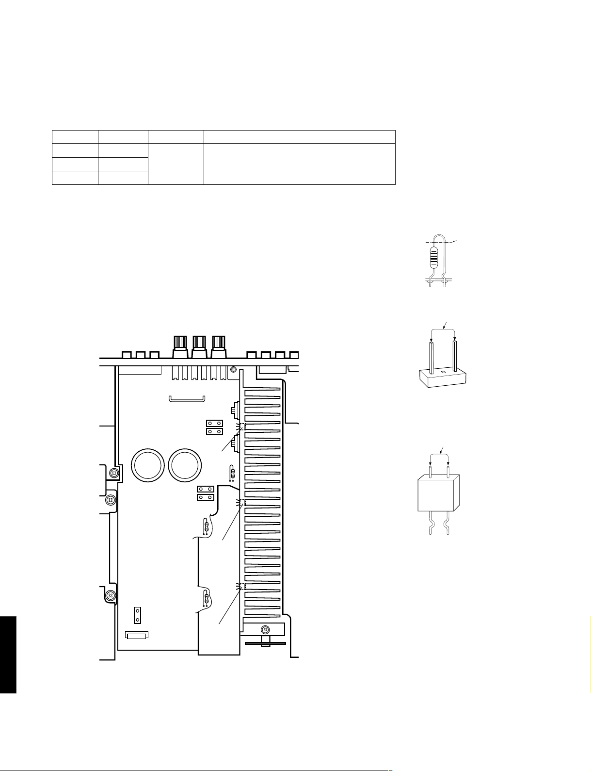
■ ADJUSTMENTS
● Confirmation of Idling Current
1) No signal applied.
2) Non-loaded condition.
3) Aging is not neccessary.
Item
REAR L
REAR R
CENTER
Test Point
CB103
R161 or R163
R167 or R169
Rating (DC)
0.1mV—5mV
Note
If the measured voltage exceeds 5.1mV, cut the
lead wire of R133(RL ch), R142(RR ch) or R150(C
ch) and then check again if each measured value
satisfies the rating.
* Confirm that the voltage is 0.12—7.5mV after 60 minutes.
Note)
• If R133 (RL ch), R142 (RR ch) or R150 (C ch) have already been cut
off and idling current does not flow, reconnect R133 (470Ω), R142
(470Ω) or R150 (470Ω).
• Q107, Q109 and Q111 are transistors for temperature compensation.
Apply silicone grease to the contact surface with the heat sink.
R161
R163
Q109
R142
R167
R133 (RL ch)
R142 (RR ch)
R150 (C ch)
Cut
0.1mV — 5mV (DC)
CB103 (RL ch)
0.1mV — 5mV (DC)
DSP-E800
5
CB103
R150
R133
R169
Q111
Q107
R161 or R163 (RR ch)
R167 or R169 (C ch)

■ SELF DIAGNOSIS FUNCTION
1. PURPOSE AND OPERATION
The DSP-E800 has a Self Diagnosis Function to locate a faulty part, if any,
by inspecting and taking measurements.
There are 12 main items in the diagnostic with sub-menu items as listed below.
DSP-E800
No.
1
2
3
4
5
6
7
8
9
10
11
12
MAIN MENU
ANALOG THROUGH
DSP THROUGH
AC–3/DTS THROUGH
PRO LOGIC
SPEAKERS SET
DISPLAY CHECK
(EFFECT OFF)
MANUAL TEST
FACTORY PRESET
AD DATA CHECK
STATUS
INFORMATION
FROM DSP
EEPROM WRITING
FUNCTION
UNIT INFORMATION/
EXIT
SUB-MENU
1. MAIN BYPASS
2. DSP 0dB
1. YSS+SRAM M
2. YSS M
3. DSP FULL BIT
1. STATUS (BINARY FORM)
1. CENTER LARGE
2. EFFECT OFF
1. MAIN : SMALL 0dB
2. MAIN : LARGE 0dB
3. MAIN : LARGE –10dB
4. LFE/BASS : MAIN
CENTER : NONE
5. LFE/BASS : MAIN
6. LFE/BASS : SUBWOOFER
7. CENTER : NONE
8. CENTER : SMALL
REAR : SMALL
9. FRONT MIX
1. (EFFECT OFF)
2. ALL SEGMENTS TURN OFF
3. ALL SEGMENTS TURN ON
4. ALTERNATE SEGMENTS TURN ON
5. SOFTWARE RELEASE DATE
1. ALL
2. MAIN L
3. CENTER
4. MAIN R
5. REAR R
6. REAR L
7. LFE
1. INHIBIT (Inhibit Memory Initialize)
2. RESERVED (Reserve Memory Initialize)
1. – – –
2. KEY1, KEY2
3. TUNER SIGNAL LEVEL
4. DC PROTECTION
5. PS PROTECTION
1./2. DSP STATUS (1)/(2)
3./4. CHANNEL STATUS (1)/(2)
5./6. BSI0 (1)/(2)
7./8. BSI1 (1)/(2)
9./10. BSI2 (1)/(2)
11./12. BSI3 (1)/(2)
13./14. BSI4 (1)/(2)
15./16. BSI5 (1)/(2)
1. CHECK SUM
MODIFICATION DATA
EEPROM DATA
2. WRITING CONFIRMATION
3. START WRITING
1. VERSION and CHECK SUM
2. MODEL TYPE and DESTINATION
3. EXIT
REMOTE CONTROL CODE (KEY)
7D–04 («1»)
– – –
7D–05 («2»)
– – –
– – –
– – –
7D–06 («3»)
– – –
7D–07 («4»)
7D–08 («5»)
7D–09 («6»)
7D–0A («7»)
7D–0B («8»)
7D–1A («TEST»)
7D–51 («SET MENU»)
– – –
7D-57 («SLEEP»)
7D-1D («EFFECT»)
– – –
– – –
– – –
– – –
– – –
– – –
– – –
– – –
– – –
– – –
– – –
– – –
– – –
– – –
– – –
– – –
– – –
– – –
– – –
– – –
– – –
– – –
– – –
– – –
– – –
– – –
– – –
– – –
– – –
– – –
– – –
– – –
DSP-E800
6

DSP-E800
2. BEGINNING AND CANCELLATION
(1) Up the function and the display
Up sub-menu No.1 of the diagnosis main is selected.
A. How to start the diagnostic program
Use the front panel keys of the main unit
Plug in the AC power cord. With the Power OFF, hold down the «PROGRAM » and «EFFECT» keys
simultaneously (Step 1), then press the «STANDBY/ON» key (Step 2).
Sub menu No. 1 of the diagnosis main menu No. 1 will start.
FRONT PANEL
«STANDBY/ON» key
«EFFECT» key
Step2. Press the «STANDBY/ON» key. Step1. Hold down the «PROGRAM »
and «EFFECT» key simultaneously.
B. Settings for start-up of diagnostic program
The settings used when starting the diagnostic program are as follows.
1.
EFFECT LEVEL :
CHANNEL CENTER R SUR L SUR SWFR
LEVEL (dB) 0 0 0 0
«PROGRAM » key
C. Start-up display
The protection history information appears on the front panel display.
DSP-E800
7
2.
MUTING : OFF
3.
INPUT (VIDEO) : DVD/LD (DVD/LD)
4.
CENTER SPEAKER : LARGE
5.
REAR SPEAKER : LARGE
6.
MAIN SPEAKER : LARGE
7.
LFE/BASS OUT : SWFR

DSP-E800
● FL display at start-up of diagnostic program
When the diagnostic program has started, the check sum of the main microcomputer or the protection history (*)
is displayed. If the protection function has been activated in the past, the type and voltage value are displayed.
After a few seconds the diagnosis function menu will appear.
(*) If a faulty condition is detected such as excessive current, a bad power supply or excessive amplifier DC offset,
the Power will be switched OFF automatically.
NOTE: For the voltages of the power and DC protection functions, see the diagnosis main menu No. 9, which will be
describbed later. The protection history will be cleared when «RESERVED» is selected in the diagnosis main menu
No. 8 and FACTORY PRESET is engaged.
● Protection history function
The following examples show how the protection history is displayed:
CHK
SUM: XXXX X
IPROTECTION
PS PRT : XX%
DC PR T : XX%
Appears when the protection function has not been activated.
Displayed the check sum (4-digit, hexadecimal) and the version (one
letter) of the main microcomputer.
Appears when the current protection function has been activated.
When power is turned on in an abnormal condition, the power relay
will come on, protection will operate immediately, and power will
turn off.
Appears when the power supply protection function has been activated.
For the % value, the voltage at that point is shown by 5V/100%.
When power is turned on in an abnormal condition, power will turn off
after half a second.
Appears when the power amp DC protection function has been
activated.
For the % value, the voltage at that point is shown by 5V/100%.
When power is turned on in an abnormal condition, power will turn off
after two seconds.
D. Exiting method
The diagnosis function can be exited by any of the following procedures. Take care with the setting of backup memory
initialization menu (diagnosis No.  when releasing the diagnosis function.
1. Select sub-menu No. 3 «EXIT» of the diagnosis main menu No. 12.
2. Press the «STANDBY/ON» key on the main unit or «STANDBY» key on the remote control to turn Power OFF.
DSP-E800
8

DSP-E800
3. OPERATION AND DISPLAY WHEN STARTING DIAGNOSIS FUNCTION
(1) Selection of diagnostic menu
The diagnostic menu and the sub-menu can be selected by using the front panel keys of the main unit or the remote
control unit.
● Selection by using the front panel keys of the main unit
The main menu can be changed cyclically by using the «SET MENU –/+» keys, and the sub-menu, by using the
«PROGRAM / » keys. The «+» and » » key will increase the main or sub-menu number.
FRONT PANEL
Reverse Forward Reverse Forward
Main menu Sub-menu
05
● Selection by using the remote control unit
The remote control codes in the menu list (see right column
on page 6) correspond to the DSP program, test, set menu, sleep
and effect keys. See the figure on the right.
(2) Other functions available while diagnosis function is active
Listed below are the other functions available while the diagnosis function is active.
• Selection of the input (include TAPE MONITOR/EXTERNAL DECODER)
• Effect level control (CENTER, REAR, SUBWOOFER)
• Master volume control
• Muting on/off
• Power on/off
04
07
0A
1A
57
06
09
08
0B
1D
51
(3) Diagnosis default status
When not otherwise specified, default settings and values in each menu are as follows:
• All “SPEAKERS” : LARGE
• ALL electronic VRs : 0dB
DSP-E800
9
• DYNAMIC RANGE : MAX
• LFE LEVEL : 0dB (–10dB in AC-3(DOLBY DIGITAL))
• CENTER DELAY : 0ms

4. CONTENTS OF DIAGNOSIS FUNCTION
This section describes the contents of the Self Diagnosis Function in detail.
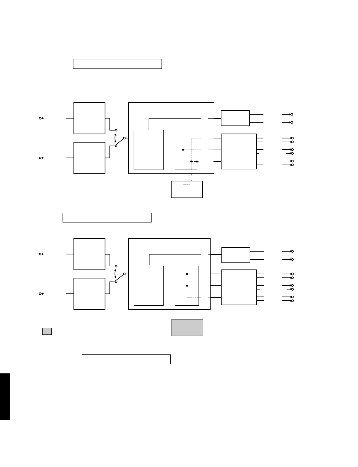
No.1 ANALOG THROUGH
The input is fixed to analog (A/D). There are two sub-menus.
DSP-E800
1. MAIN BYPASS
1. MAIN BYPASS
The L/R signals bypass the digital circuit, and are output to the MAIN L/R.
The L/R signals are output without being processed to the CENTER/SUBWOOFER, FRONT L/R and REAR L/R
through the DSP. (Remote control code 7D-04: «1» key)
CODEC.ADC
ANALOG IN
AC3D2av(YSS918)
L/R
DAC
AK4324
MAIN L
MAIN R
AK4526A
DECODER
DIR5
DIGITAL IN
YSD917
DOLBY DIGITAL
or
PRO LOGIC
or
DTS
: This shows that the device is not operating.
2. DSP 0dB
1. DSP 0DB
The L/R signals are output without being precessed to the MAIN L/R through the AC3D2av.
The L/R signals are output without being precessed to the CENTER/SUBWOOFER, FRONT L/R and REAR L/R through
the DSP.
DSP
L/R L/R
L/R
L/R
1M SRAM
CODEC.DAC
AK4526A
• INPUT : DVD/LD (Analog signal)
(Lch and Rch, 1KHz, –20dBV)
• OUTPUT : PRE OUT
MAIN L : –3.5 dBV REAR L : –3.5 dBV
MAIN R : –3.5 dBV REAR R : –3.5 dBV
CENTER: –3.5 dBV
FRONT L
FRONT R
CENTER
SUBWOOFER
REAR L
REAR R
CODEC.ADC
ANALOG IN
AK4526A
DIR5
DIGITAL IN
YSD917
: This shows that the device is not operating.
AC3D2av(YSS918)
DECODER
DOLBY DIGITAL
or
PRO LOGIC
or
DTS
L/R L/R
DSP
1M SRAM
L/R
DAC
AK4324
CODEC.DAC
L/R
L/R
• INPUT : DVD/LD (Analog signal)
• OUTPUT : PRE OUT
AK4526A
(Lch and Rch, 1KHz, –20dBV)
MAIN L : –3.5 dBV REAR L : –3.5 dBV
MAIN R : –3.5 dBV REAR R : –3.5 dBV
CENTER: –3.5 dBV
SUBWOOFER
MAIN L
MAIN R
FRONT L
FRONT R
CENTER
REAR L
REAR R
DSP-E800
10
DSP-E800
No.2 DSP THROUGH
The input is automatically discriminated by signal detection and switched with priorities Coaxial>Optical>Analog.
There are the following three sub-menus.
1. YSS+SRAM
2. YSS + SRAM M
The L/R signals are output without being processed to the MAIN L/R through the AC3D2av.
The L/R signals are output without being processed to the CENTER/SUBWOOFER through the DSP.
The (L+R)/2 signals are output to the FRONT L/R and REAR L/R through the DSP and the SRAM.
When one of the L/R signals is not input, the output level is –6dB. (Remote control code 7D-05:»2″ key)
CODEC.ADC
ANALOG IN
AC3D2av(YSS918)
L/R
DAC
AK4324
AK4526A
DECODER
DOLBY DIGITAL
or
PRO LOGIC
or
DTS
DIGITAL IN
2. YSS M
DIR5
YSD917
2. YSS M
Same as «2. DSP 0dB» of «No.1 ANALOG THROUGH», except for the input switching.
L/R
DSP
(L+R)/2(L+R)/2
1M SRAM
L/R
L/R
(L+R)/2
CODEC.DAC
AK4526A
• INPUT : DVD/LD (Analog signal)
(Lch and Rch, 1KHz, –20dBV)
• OUTPUT : PRE OUT
MAIN L : –3.5 dBV REAR L : –3.5 dBV
MAIN R : –3.5 dBV REAR R : –3.5 dBV
CENTER: –3.5 dBV
MAIN L
MAIN R
FRONT L
FRONT R
CENTER
SUBWOOFER
REAR L
REAR R
CODEC.ADC
ANALOG IN
AC3D2av(YSS918)
L/R
DAC
AK4324
MAIN L
MAIN R
AK4526A
DECODER
DIR5
DIGITAL IN
YSD917
DOLBY DIGITAL
or
PRO LOGIC
or
DTS
: This shows that the device is not operating.
3. DSP FULL BIT
2. DSP FULL BI T
Same as the above menu, except that the head margin is disabled, and the digital data is output with full bits from
AC3D2av to DAC.
DSP
L/R L/R
L/R
L/R
1M SRAM
CODEC.DAC
AK4526A
• INPUT : DVD/LD (Analog signal)
(Lch and Rch, 1KHz, –20dBV)
• OUTPUT : PRE OUT
MAIN L : –3.5 dBV REAR L : –3.5 dBV
MAIN R : –3.5 dBV REAR R : –3.5 dBV
CENTER: –3.5 dBV
• INPUT : DVD/LD (Analog signal)
(Lch and Rch, 1KHz, –20dBV)
• OUTPUT : PRE OUT
MAIN L : –3.5 dBV REAR L : 5.0 dBV
MAIN R : –3.5 dBV REAR R : 5.0 dBV
CENTER: –1.0 dBV
FRONT L
FRONT R
CENTER
SUBWOOFER
REAR L
REAR R
DSP-E800
11

No.3 AC-3/DTS THROUGH
The input is digital signal only. AC-3 (DOLBY DIGITAL) or DTS Digital Surround decoding operation is executed,
according to the input source.
bit 7
bit 1
DSP-E800
1. STATUS(BINARY FORM)
3. ST: 10001001
AC-3 (DOLBY DIGITAL) decoded signals are output to each channel via AC3D2av.
The AC-3 (DOLBY DIGITAL) signal status data will be displayed in the FL display using a binary number.
CODEC.ADC
ANALOG IN
AC3D2av(YSS918)
L/R
DAC
AK4324
AK4526A
DSP
CODEC.DAC
C/LFEC/LFE
LS/RSLS/RS
AK4526A
SUBWOOFER
DIGITAL IN
DIR5
DECODER
DOLBY DIGITAL
or
PRO LOGIC
or
DTS
YSD917
: This shows that the device is not operating.
AC-3 Status Info. : bit7 6 5 4 3 2 1 0
(Invalid in DTS) 1 0 0 01001
IEC958 digital data bit
IEC958 commercial-use device bit
IEC958 digital format error
Demodulator muting (without RF signal)
1 for audio other than PCM linear audio
1 during red DTS lock (Flashes and lights)
1 during DTS decode OK
1 during AC-3 decode OK
1M SRAM
MAIN L
MAIN R
CENTER
REAR L
REAR R
No.4 PRO LOGIC
The sub-menu is switched between PRO LOGIC (AUTO BALANCE OFF) and EFFECT OFF.
1. CENTER LARGE
4. PRO CNTR: LRG
The input is automatically discriminated by signal detection and switched with priorities Coaxial>Optical>Analog.
DTS Digital Surround is disabled. The input signals are PRO LOGIC decoded and output.
(Remote control code 7D-06: «3» key)
CODEC.ADC
ANALOG IN
AC3D2av(YSS918)
L/R
DAC
AK4324
AK4526A
DECODER
DSP
CODEC.DAC
DIR5
DIGITAL IN
DOLBY DIGITAL
or
PRO LOGIC
or
DTS
C
S
C
S
AK4526A
YSD917
• INPUT : DVD/LD (Analog signal)
(Lch and Rch, or Lch only, 1KHz, –20dBV)
1M SRAM
2. EFFECT OFF
4. PRO EFCT : OFF
The input is only for analog signal. The L/R signals bypass the digital circuit and are output to the MAIN L/R.
• OUTPUT : PRE OUT
(INPUT : Lch and Rch ) (INPUT : Lch only)
MAIN L : – ∞ dBV MAIN L : –3.5 dBV
MAIN R : – ∞ dBV MAIN R : – ∞ dBV
CENTER: –0.5 dBV CENTER : – ∞ dBV
REAR L : – ∞ dBV REAR L : – ∞ dBV
REAR R : – ∞ dBV REAR R : – ∞ dBV
MAIN L
MAIN R
CENTER
REAR L
REAR R
DSP-E800
12

DSP-E800
No.5 SPEAKERS SET
The input is automatically discriminated by signal detection and switched with priorities Coaxial>Optical>Analog.
The L/R signals are output to channels specified by the sub-menu without being processed.
There are the following nine sub-menus items. Signal routes of the sub-menu 1-4 are the same as EFFECT OFF.
But MAIN L/R are signals through the digital circuit.
Signal routes of the sub-menu 5-9 are the same as «2. YSS M» of «No. 2 DSP THROUGH».
However, only MAIN L/R is output in the sub-menu 1-4.
5. MA I N : SML 0DB
5. B : MA I N C : NON
5. C : NONE
5. MA I N : LRG 0 DB
5. LFE / B : MAIN
5. C : S REAR : S
5. MA I N : LRG — 1 0
5. LFE / B : SWFR
5. FRONT M I X
The analog switches in each sub-menu are set as follows:
SUB MENU
1 MAIN:SML 0DB 7D-07 LARGE LARGE SMALL 0dB SWFR L R NONE NONE NONE L+R
2 MAIN:LRG 0DB 7D-08 LARGE LARGE LARGE 0dB SWFR L R NONE NONR NONE NONE
3 MAIN:LRG -10 7D-09 LARGE LARGE LARGE -10dB SWFR L R NONE NONE NONE NONE
4 B:MAIN C:NONE 7D-0A NONE LARGE LARGE 0dB MAIN L R NONE NONE NONE NONE
5 LFE/B:MAIN 7D-0B LARGE LARGE LARGE 0dB MAIN
6 LFE/B:SWFR 7D-1A LARGE LARGE LARGE 0dB SWFR NONE NONE NONE NONE NONE LFE
7 C:NONE 7D-51 NONE LARGE LARGE 0dB SWFR C+L C+R NONE NONE NONE LFE
8 C:S REAR:S – – – SMALL SMALL LARGE 0dB SWFR L+FL R+FR C RL RR
9 FRONT MIX 7D-57 LARGE LARGE LARGE 0dB SWFR FL FR NONE NONE NONE NONE
REMOTE
CONTROL
CODE
CENTER SP
MAIN SPREAR SP
MAIN
LEVEL
LFE/BASS
MAIN
MAIN
L
R
LFE+FLLFE+FR
OUTPUTSETTING
REAR
CENTER
REAR
C NONE NONE NONE
R
L
SUB
WOOFER
C+RL+RR+LFE
LARGE: Mode in which speakers with high bass-sound playback capability (large unit) are used. Full-range signals present
on the channel are output from the speaker.
SMALL: Mode in which speakers with low bass-sound playbac k capability (small unit) are used. Low bass signals (below
90Hz) on the channel are mixed into the channel selected by the LFE/BASS setting.
NONE: Mode in which center speaker is not used. The center channel signal is reduced by 3 dB and mixed into MAIN L/R.
LFE/B:MAIN
:Mode in which subwoofer speaker is not used. The LFE channel signal is reduced by 4.5 dB and mixed into
MAIN L/R. But because of the phase difference, the MAIN L/R output is not simply summed.
Description of the submenu as follows:
1 MAIN:SML 0DB Verification of the High and low pass filter response and gain in the bass redirection mode.
2 MAIN:LRG 0DB Reference of the sub menu No. 1 and 2.
3 MAIN:LRG -10 Verification of the effect in the main level function.
4 B:MAIN C:NONE Verification of the mixing circuit effect to the main channel.
5 LFE/B:MAIN Verification of the bass mix gain.
6 LFE/B:SWFR Verification of the LFE maximum output.
7 C:NONE Verification of the center mix gain.
8 C:S REAR:S Verification of the high and low pass filter response and gain in the bass redirection mode.
9 FRONT MIX Verification of the front mix gain.
DSP-E800
13
SUB MENU DESCRIPTION

No.6 DISPLAY CHECK
Check program for FL display. The display status will change as follows with sub-menu operation.
The input becomes «6CH EXTERNAL» when all segments turn off and changes to «6CH MAIN IN»
when all segments turn on.
DSP-E800
6. VFD
Initial display
(Remote control code 7D-1D:»EFFECT» key)
A defect of the FL drive port and FL display segments can be detected by using «All segments turn off» and «All
segments turn on».
A short-circuit between adjacent segments can be detected by using «Alternate segments turn on» (lattice form).
No.7 MANUAL TEST
By using the noise generator built into the DSP, test noise outputs to the channel specified by the sub-menu.
CHCK
7. TEST ALL
7. TEST MA I N R
All segments turn off
(«6CH Ext» input)
Software Release date display
7. TEST MA I N L
7. TEST REAR R
All segments turn on
(«6CH MAIN IN» input)
Alternate segments turn on (lattice form)
7. TEST CENTER
7. TEST REAR L
7. TEST LFE
No.8 FACTORY PRESET
The initialization of the back-up RAM, which contains DSP program, set menu contents, etc. is reserved
or inhibited.
8. PRESET
INHI
8. PRES E T RSRVD
1. INHIBIT: Inhibits initialization of the back-up RAM.
Using this option protect user set values.
2. RESERVED: Reserve to initialization of the back-up RAM.
(The RAM is actually initialized when power
is turned on next time.) This option is used for
the factory preset or to reset the RAM.
For the contents of the initialization, see page 18.
The protection data is also reset.
DSP-E800
14
DSP-E800
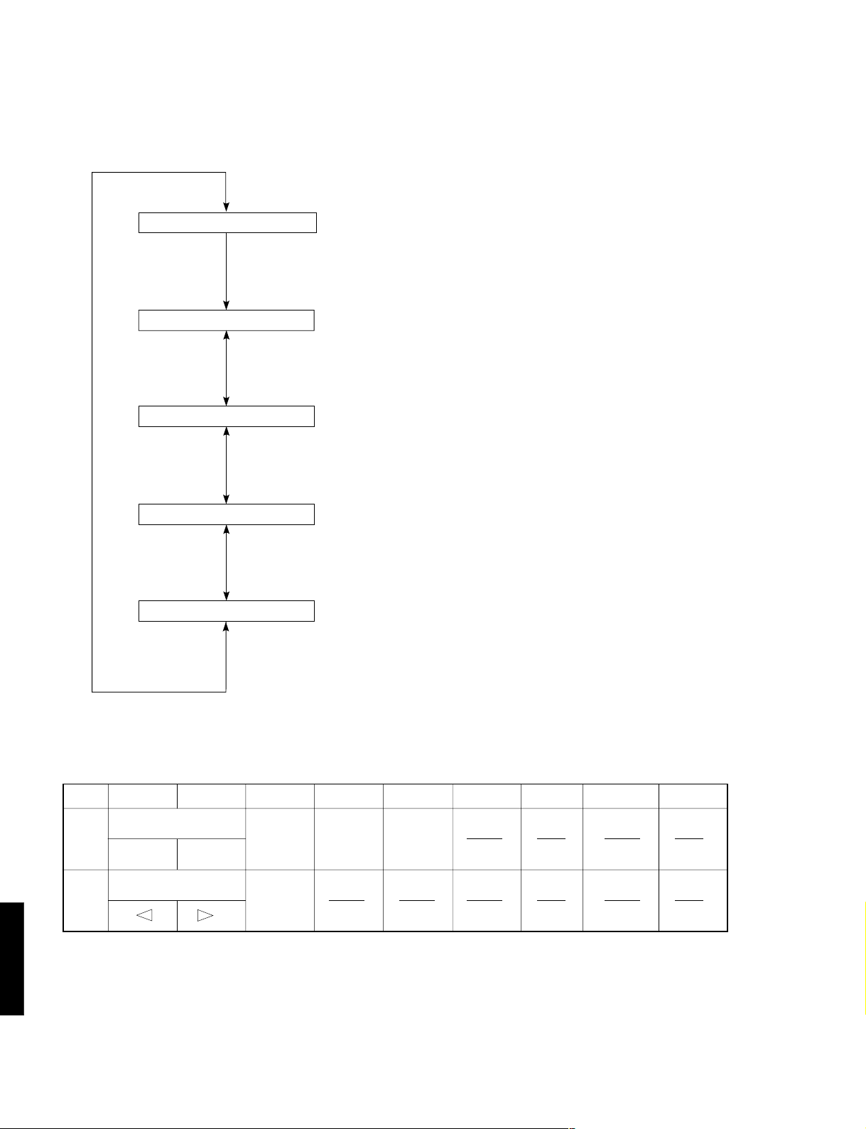
No.9 AD DATA CHECK
The A/D conversion values of the microcomputer which detects key scan port, protection detection port, etc. are displayed
in % (100%:5V).
The keys on the main unit cannot be operated to detect the values of all keys in the K1/K2 and SI.
Turning the rotary encoder (input selector on the main unit) will switch the sub-menu.
9. AD DAT A CHK
9. K1 : 1 00K2 : 1 00
9. S I
:
0
9. DC : 7
9. PS : 3 0
Initial display.
K1/K2: Panel key on the main unit.
(See Table 1.)
SI: Tuner signal sensitivity level
Ignore this display item as this unit is not equipped with a tuner.
DC: DC protection value
(normal value: 1-13)
PS: Power voltage protection value
(normal value: 23-38)
Table 1
AD Value
K1
K2
Cautions:
1. If K1 and K2 are more than ±4% from the reference values, normal operation will not be executed.
2. If DC and PS are outside the nor mal values, the protection function will operate and power will turn off.
DSP-E800
15
01525354555657585
SET MENU
NEXT
– +
PROGRAM
INPUT MODE
TAPE/MD MON
/EXT DECODER
EFFECT
Loading…
Yamaha DSP-E800
YAMAHA ELECTRONICS CORPORATION, USA 6660 ORANGETHORPE AVE., BUENA PARK, CALIF. 90620, U .S.A.
YAMAHA CANADA MUSIC LTD. 135 MILNER AVE., SCARBOROUGH, ONTARIO M1S 3R1, CANA DA
YAMAHA ELECTRONIK EUROPA G.m.b.H. SIEMENSSTR. 22-34, 25462 RELLINGEN BEI HAMBURG, F.R. OF GERMANY
YAMAHA ELECTRONIQUE FRANCE S.A. RUE AMBROISE CROIZAT BP70 CROISSY-BEAUBOURG 77312 MA RNE-LA-VALLEE CEDEX02, FRANCE
YAMAHA ELECTRONICS (UK) LTD. YAMAHA HOUSE, 200 RICKMANSWORTH ROAD WATFORD, HERTS WD1 7JS, ENGLAND
YAMAHA SCANDINAVIA A.B. J A WETTERGRENS GATA 1, BOX 30053, 400 43 VÄSTRA FRÖUNDA, SWEDEN
YAMAHA MUSIC AUSTRALIA PTY, LTD. 17-33 MARKET ST., SOUTH MELBOURNE, 3205 VIC., AUSTR ALIA
Printed in Malaysia V584180
BG
AV PROCESSOR/AMPLIFIER
AMPLIFICATEUR D’EFFETS AUDIO-VIDEO
OWNER’S MANUAL
MODE D’EMPLOI
BEDIENUNGSANLEITUNG
BRUKSANVISNING
MANUALE DI ISTRUZIONI
MANUAL DE INSTRUCCIONES
GEBRUIKSAANWIJZING
DSP-E800
Manual
View the manual for the Yamaha DSP-E800 here, for free. This user manual comes under the category receivers and has been rated by 1 people with an average of a 8.2. This manual is available in the following languages: English. Do you have a question about the Yamaha DSP-E800?
Ask your question here
Index
- English
- Français
- Deutsch
- Svenska
- Italiano
- Español
- Nederlands
Product Images (2)

Yamaha DSP-E800 specifications
Below you will find the product specifications and the manual specifications of the Yamaha DSP-E800.
The Yamaha DSP-E800 receiver is a home audio device that offers various features for enhancing sound quality and providing an immersive listening experience. This receiver comes equipped with multiple inputs and outputs, allowing for connection to different audio sources such as TVs, DVD players, and gaming consoles. It also includes built-in digital signal processing technology, which helps to optimize sound reproduction and create a more dynamic audio environment.
Additionally, the Yamaha DSP-E800 receiver offers customizable sound settings and presets, allowing users to adjust the sound to their preference. It provides support for various audio formats, including Dolby Digital and DTS, for a more cinematic sound experience. The receiver also includes a remote control for easy operation and convenience.
Overall, the Yamaha DSP-E800 receiver is designed to deliver high-quality audio performance and enhance the listening experience for users. With its advanced features and customizable settings, this receiver is suitable for those looking to upgrade their home audio system.
General
| Brand | Yamaha |
| Model | DSP-E800 | DSP-E800 |
| Product | receiver |
| Language | English |
| Filetype | Manual (PDF) |
Frequently asked questions
Can’t find the answer to your question in the manual? You may find the answer to your question in the FAQs about the Yamaha DSP-E800 below.
Can bluetooth devices of different brands be connected to each other?
Yes, bluetooth is a universal method that allows different devices equipped with bluetooth to connect to each other.
What is bluetooth?
Bluetooth is a way of exchanging data wirelessly between electronic devices via radio waves. The distance between the two devices that exchange data can in most cases be no more than ten metres.
What is HDMI?
HDMI stands for High-Definition Multimedia Interface. An HDMI cable is used to transport audio and video signals between devices.
When is my volume too loud?
A volume above 80 decibels can be harmful to hearing. When the volume exceeds 120 decibels, direct damage can even occur. The chance of hearing damage depends on the listening frequency and duration.
How can I best clean my receiver?
A slightly damp cleaning cloth or soft, dust-free cloth works best to remove fingerprints. Dust in hard-to-reach places is best removed with compressed air.
Wat is Dolby Atmos?
Dolby Atmos is a technology that ensures that the sound is reflected from the ceiling to where you are listening. This makes it possible to create a 5.1 effect with only 1 speaker.
Is the manual of the Yamaha DSP-E800 available in English?
Yes, the manual of the Yamaha DSP-E800 is available in English .
Is your question not listed? Ask your question here
- Addeddate
- 2022-01-16 08:15:21
- Identifier
- manuallib-id-2655842
- Identifier-ark
- ark:/13960/s2v9qrp7nnp
- Ocr
- tesseract 5.0.0-1-g862e
- Ocr_autonomous
- true
- Ocr_detected_lang
- en
- Ocr_detected_lang_conf
- 1.0000
- Ocr_detected_script
-
Latin
Greek
- Ocr_detected_script_conf
-
0.9918
0.0077
- Ocr_module_version
- 0.0.14
- Ocr_parameters
- -l lat+eng+ell+Greek+Latin
- Ppi
- 300
comment
Reviews
There are no reviews yet. Be the first one to
write a review.
57
Views
DOWNLOAD OPTIONS
Temporarily Unavailable
DAISY
For users with print-disabilities
Temporarily Unavailable
EPUB
Uploaded by
chris85
on
Yamaha DSP-E800 Amplifier Specification
The Yamaha DSP-E800 Amplifier is a versatile home audio component designed to enhance the auditory experience of both music and home theater systems. It features a robust power output, delivering high-quality sound across a wide frequency range. Equipped with Yamaha’s proprietary Digital Sound Processing technology, the DSP-E800 offers an immersive audio experience by providing multiple sound field programs tailored for various types of content, including movies, music, and gaming.
The amplifier supports Dolby Digital and DTS decoding, ensuring compatibility with a broad range of modern audio formats for a true surround sound experience. It includes three built-in amplifiers that can be used to drive additional speakers, enhancing the depth and realism of the audio environment. With multiple input and output options, including optical and coaxial digital inputs, the DSP-E800 can easily integrate with existing audio-visual setups, offering flexibility and convenience.
The front panel features intuitive controls and a clear display, allowing users to adjust settings and switch between modes with ease. Additionally, the amplifier comes with a remote control, providing added convenience for users to manage their audio settings from a distance. The DSP-E800’s design incorporates advanced circuitry to minimize distortion and maximize signal clarity, ensuring a clean and dynamic sound output.
With its comprehensive feature set, including Yamaha’s CINEMA DSP technology, this amplifier is ideal for audio enthusiasts seeking to elevate their home entertainment systems. Its ability to reproduce clear and powerful sound, combined with its user-friendly interface, makes the Yamaha DSP-E800 a formidable choice for those looking to enhance their audio setup.
Yamaha DSP-E800 Amplifier F.A.Q.
To connect external devices, use the appropriate input ports on the back of the amplifier. For audio, use the RCA inputs, and for digital audio, use the optical or coaxial inputs. Ensure that each device is set to the correct input source on the amplifier.
First, check that the speakers are properly connected to the amplifier. Ensure the amplifier is set to the correct input source and that the volume is turned up. Verify that the mute function is not activated and check for any blown fuses.
To perform a factory reset, turn off the amplifier, then press and hold the «Program» and «Tone Control» buttons while turning the unit back on. This will reset the settings to factory defaults.
Regularly dust the exterior and ensure vents are clear of obstructions. Annually check connections for wear and clean the connectors. If used frequently, consider a professional service check every 2-3 years.
Yes, you can connect the amplifier to a modern TV using the optical or coaxial digital audio outputs from the TV to the corresponding inputs on the amplifier.
Ensure the amplifier is in a well-ventilated area and that vents are not blocked. Check the impedance of the connected speakers and reduce the volume if necessary. If overheating persists, consult a professional technician.
The Yamaha DSP-E800 does not support firmware updates as it is an older model. Ensure all connections and settings are optimized for best performance.
This may be due to overheating or a protection circuit being triggered. Check for proper ventilation, correct speaker impedance, and ensure there are no short circuits in the speaker wiring.
Use the remote control to access the setup menu. Navigate to the surround sound settings and adjust parameters like speaker size, distance, and levels to match your room setup.
The Yamaha DSP-E800 does not have built-in Bluetooth. However, you can use an external Bluetooth adapter connected to the auxiliary or RCA inputs to stream audio wirelessly.
-
Contents
-
Table of Contents
-
Troubleshooting
-
Bookmarks
-
Français
-
Introduction
-
Les Commandes Et Leurs Fonctions
-
Préparation
-
Installation des Enceintes
-
Équilibrage du Son entre Les Enceintes
-
-
Utilisation de Base
-
Effet du Processeur de Champ Sonore Numérique (Dsp)
-
Enregistrement D’une Source Sur Une Cassette, un Minidisc Ou Une Cassette VIDéo
-
Utilisation Avancée
-
Réglage du Temps de Retard Et du Niveau de Sortie des Enceintes
-
Minuterie de Mise en Veille
-
Annexes
-
Caractéristiques Techniques
-
-
Deutsch
-
Einleitung
-
-
Verwendung der Fernbedienung
-
-
Bedienungselemente und Funktionen
-
Vorbereitungen
-
Einstellen der Lautsprecherbalance
-
Grundlegende Bedienung
-
Wiedergabe einer Signalquelle
-
Effekte des Digitalen Klangfeldprozessors (Dsp)
-
Aufnahme einer Signalquelle auf
-
-
Weiterführende Funktionen
-
Verzögerungszeit und Lautsprecher-Ausgangspegel
-
Anhang
-
-
Svenska
-
Inledning
-
Kontrollerna Och Deras Funktioner
-
Förberedelser
-
Justering Av Balansen Mellan Högtalarna
-
Grundläggande Användningssätt
-
Den Digitala Ljudfältsprocessorn (Dsp)
-
Avancerad Användning
-
Inställningsmenyn «Set Menu
-
Justering Av Fördröjningstiden Och Högtalarnas Utnivåer
-
-
Italiano
-
Introduzione
-
Preparativi
-
Sostituzione Delle Batterie
-
Posizionamento Degli Altoparlanti
-
Regolazione del Bilanciamento Degli Altoparlanti
-
-
Operazioni Fondamentali
-
Riproduzione DI una Sorgente
-
Effetto del Processore Digitale del Campo Sonoro (Dsp)
-
Registrazione DI una Sorgente Su un Nastro, MD O Videocassetta
-
-
Operazioni Avanzate
-
Programma DI Campo Sonoro
-
Tempo DI Ritardo E Livelli DI Uscita Degli Altoparlanti
-
Timer Per lo Spegnimento Automatico
-
-
Appendice
-
-
Español
-
Introducción
-
Preparación
-
Instalación de Los Altavoces
-
Ajuste del Balance de Los Altavoces
-
-
Funcionamiento Básico
-
Reproducción de una Fuente
-
Efecto del Procesador de Campo de Sonido Digital (Dsp)
-
Para Grabar una Fuente en una Cinta, MD O Videocasete
-
-
Funcionamiento Avanzado
-
Programa de Campo de Sonido
-
Tiempo de Retardo y Niveles de Salida de Los Altavoces
-
-
Apéndice
-
-
Dutch
-
Inleiding
-
-
Gebruik Van de Afstandsbediening
-
-
Bedieningsorganen en Hun Functies
-
-
Voorbereiding
-
Opstelling Van de Luidsprekers
-
Afstelling Van de Luidsprekerbalans
-
-
Basisbediening
-
Effect Van Digitale Geluidsveldprocessor (Dsp)
-
Opnemen Van Een Bron Op Tape, MD of Videocassette
-
Vertragingstijd en Luidspreker-Uitgangsniveaus
-
Addendum
-
BG
DSP-E800
AV PROCESSOR/AMPLIFIER
AMPLIFICATEUR D’EFFETS AUDIO-VIDEO
OWNER’S MANUAL
MODE D’EMPLOI
BEDIENUNGSANLEITUNG
BRUKSANVISNING
MANUALE DI ISTRUZIONI
MANUAL DE INSTRUCCIONES
GEBRUIKSAANWIJZING