
54699
Если в предыдущей статье мы рассматривали больше внешний вид, характеристики и возможности наружных точек доступа TP-Link CPE510, то в этой статье поговорим о их настройках. Это профессиональные устройства, и желательно, чтобы их настраивали профессионалы. Нужно соблюдать порядок установки и подключения для сохранения гарантии, так же необходимо соблюдать местные правила в отношении использования радиочастот, каналов, мощности сигнала. Так как в зависимости от региона, могут быть установлены разные ограничения. Об этом написано сразу при входе в настройки TP-Link CPE510.
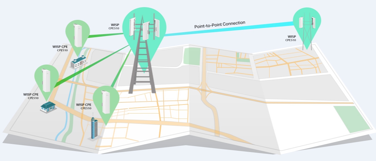
Поэтому, если вы хотите построить сеть из нескольких наружных точек доступа, на большое расстояние, то лучше обратится к специалистам. В этой статье я просто ознакомлю вас с некоторыми возможностями этих наружных точек доступа. Покажу, как выполнить вход в панель управления TP-Link CPE510, и настроить эти устройства в двух режимах «Точка доступа» и «Клиент». Именно в этих режимах чаще всего настраивают данные устройства. В том числе для установки Wi-Fi соединения на большом расстоянии (до 15 километров).
Так как это наружные точки доступа, и они будут установлены с наружной стороны здания, то желательно заранее продумать схему подключения и проложить все необходимые кабеля. Так же изготовить кронштейн для крепления самого устройства. Сделать заземление.
В большинстве случаев, к TP-Link CPE510 будет идти один сетевой кабель. От маршрутизатора (провайдера), или к маршрутизатору, компьютеру, или другому устройству. Питание по PoE (по сетевому кабелю). Это сильно упрощает процесс монтажа.
Как настроить Wi-Fi соединение на большое расстояние?
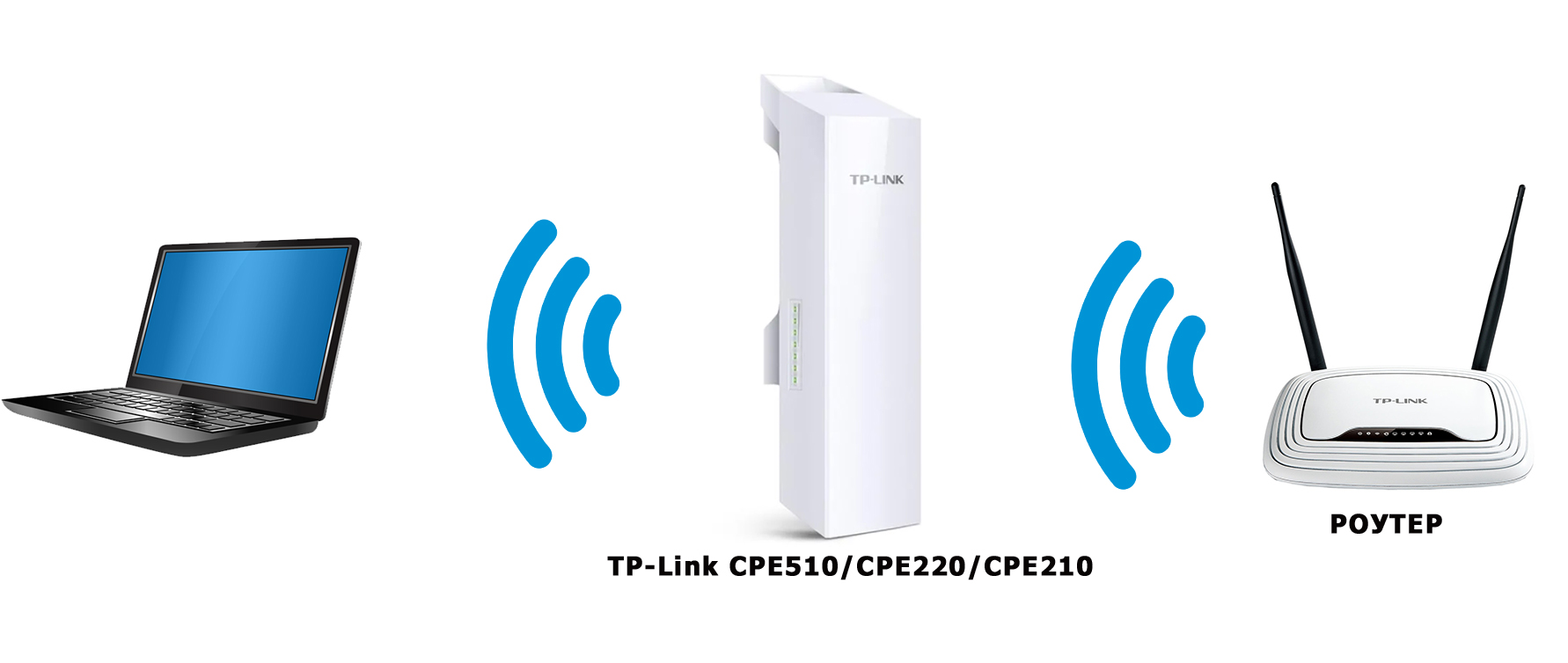
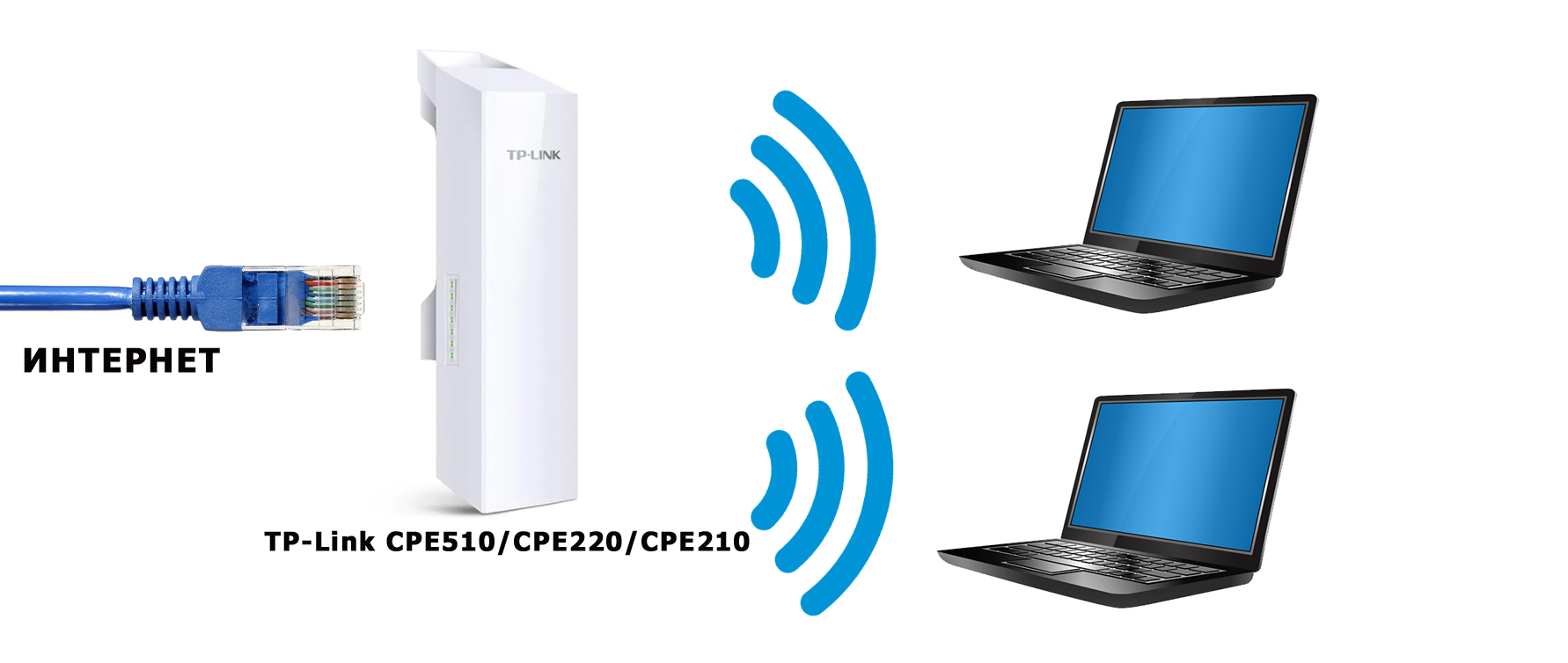
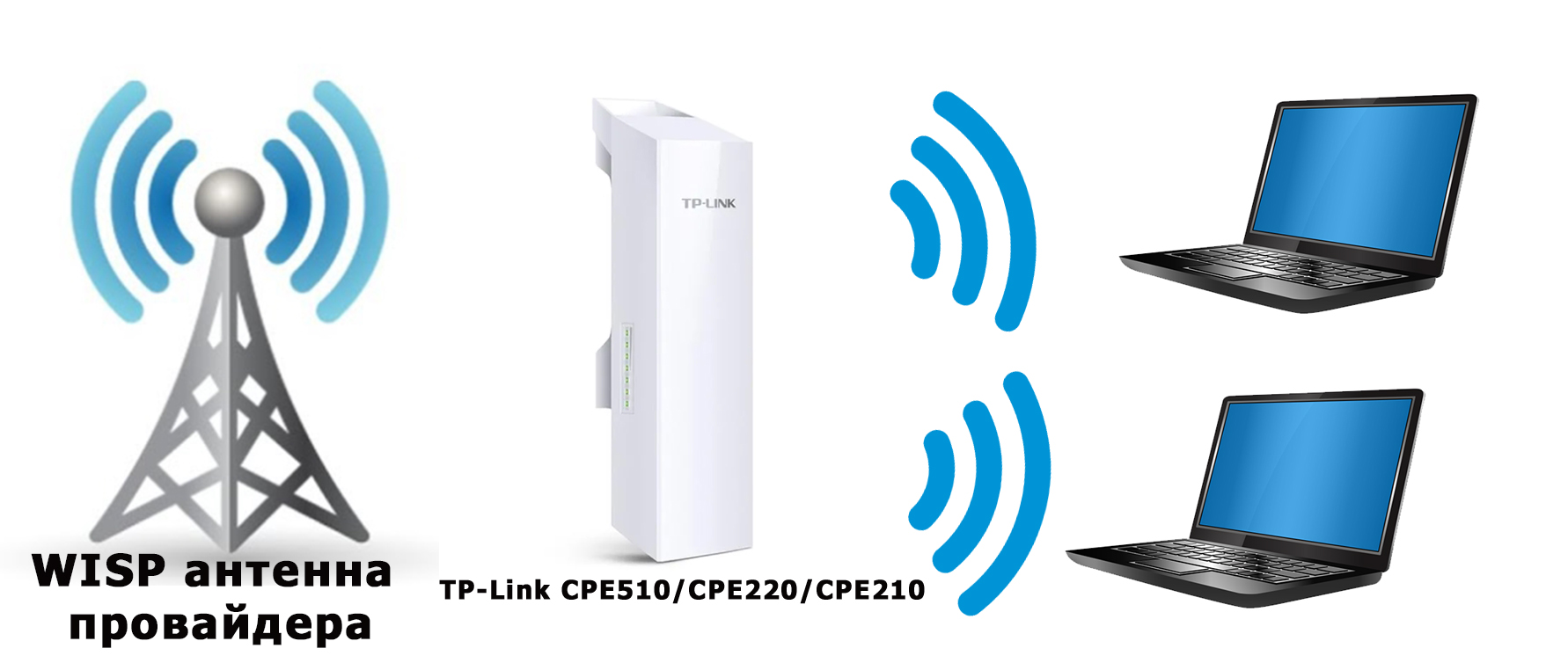
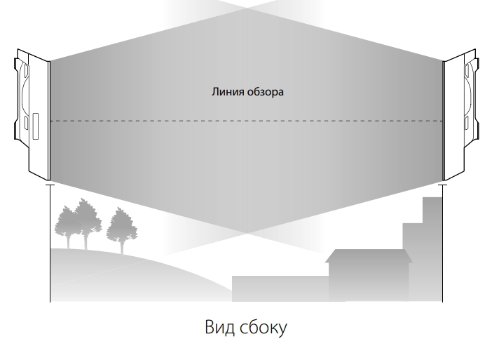
Понадобится две точки доступа. Например, TP-Link CPE510. Их нужно закрепить на двух зданиях таким образом, чтобы они были в зоне прямой видимости. И направить примерно друг на друга. Когда уже все будет настроено, то можно будет более точно настроить их ориентируясь по показателям в панели управления. Одна ТД будет настроена в режиме «Точка доступа» (передавать сигнал), а вторая как «Клиент» (принимать сигнал).

Если рассматривать конкретно модель CPE510, то их можно соединить на расстоянии до 15 километров.
Как зайти в настройки наружной точки доступа TP-Link?
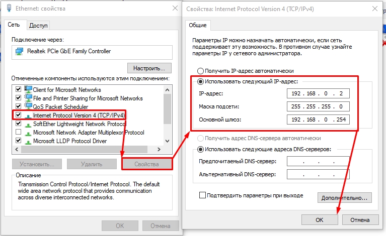
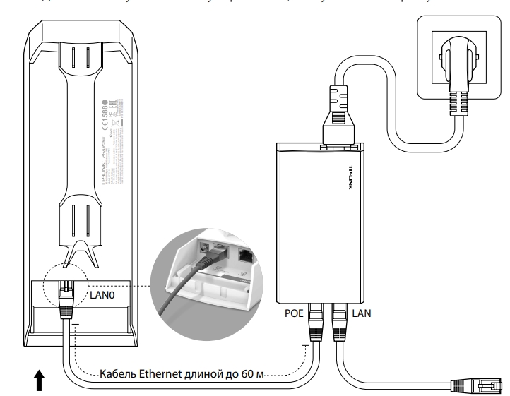
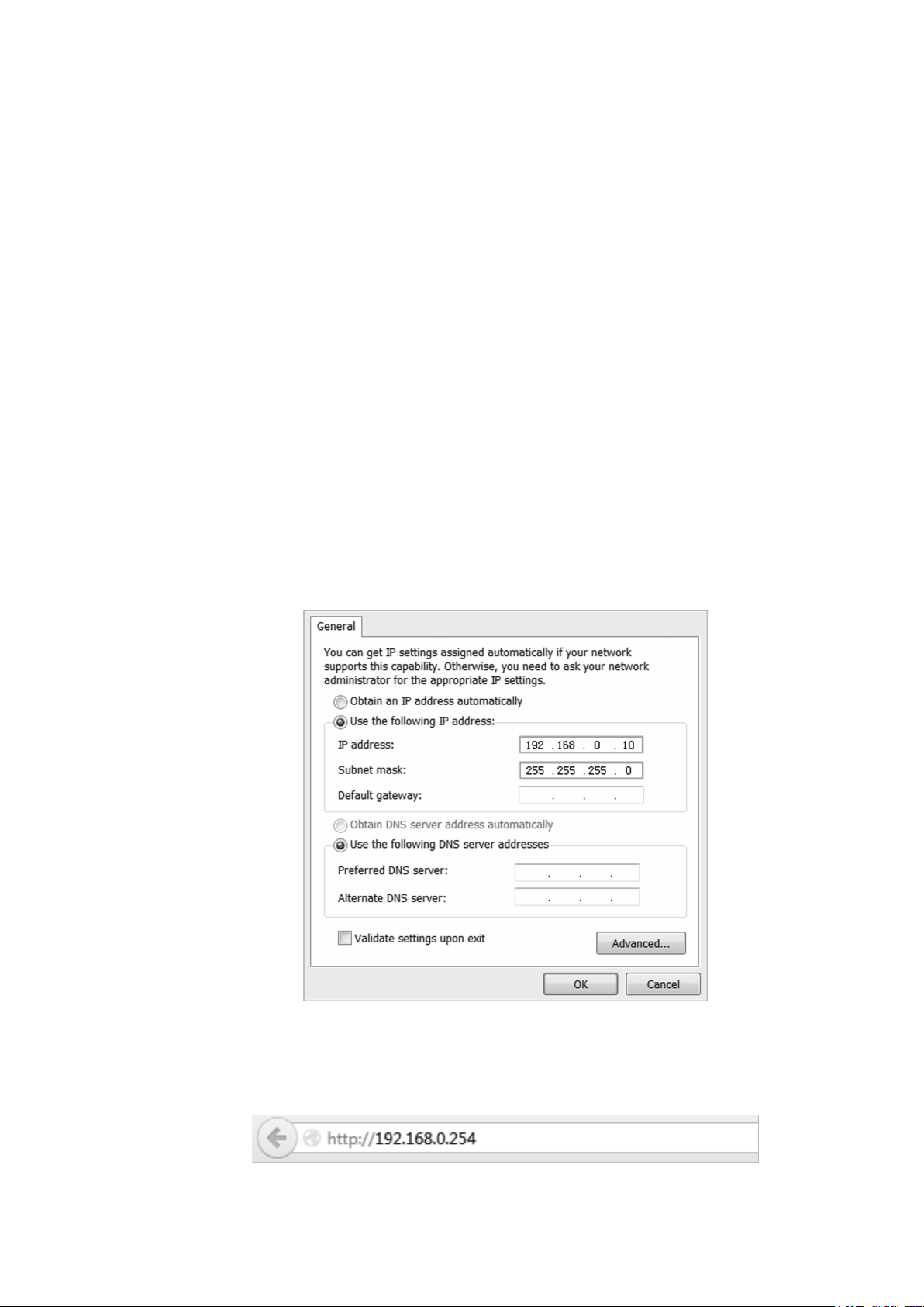
Чтобы выполнить вход в настройки TP-Link CPE510, нужно сначала настроить параметры сетевой карты компьютера. Но перед этим можете подключить устройство к компьютеру. Нужно два сетевых кабеля. Первый подключаем на адаптере в порт POE, и в порт LAN0 (POE IN) на точке доступа. А второй кабель подключаем на адаптере в порт LAN и к компьютеру, или ноутбуку.

В свойствах сетевого адаптера (Ethernet), для протокола IPv4 нужно прописать статические адреса. IP-адрес прописываем например 192.168.0.2, маска подсети будет выставлена автоматически, а в поле основной шлюз указываем 192.168.0.254.

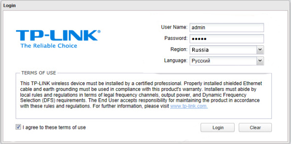
Заводской IP-адрес TP-Link CPE510 – 192.168.0.254. Логин и пароль – admin/admin. Открываем браузер и переходим по адресу http://192.168.0.254. На первой странице указываем логин и пароль (admin/admin), выбираем регион и язык панели управления. Читаем правила использования, ставим галочку приняв их и продолжаем нажав на кнопку «Login».

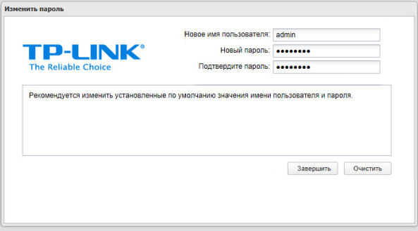
Дальше устройство предложит изменить заводской пароль admin на более сложный. Указываем два раза новый пароль и нажимаем на кнопку «Завершить».

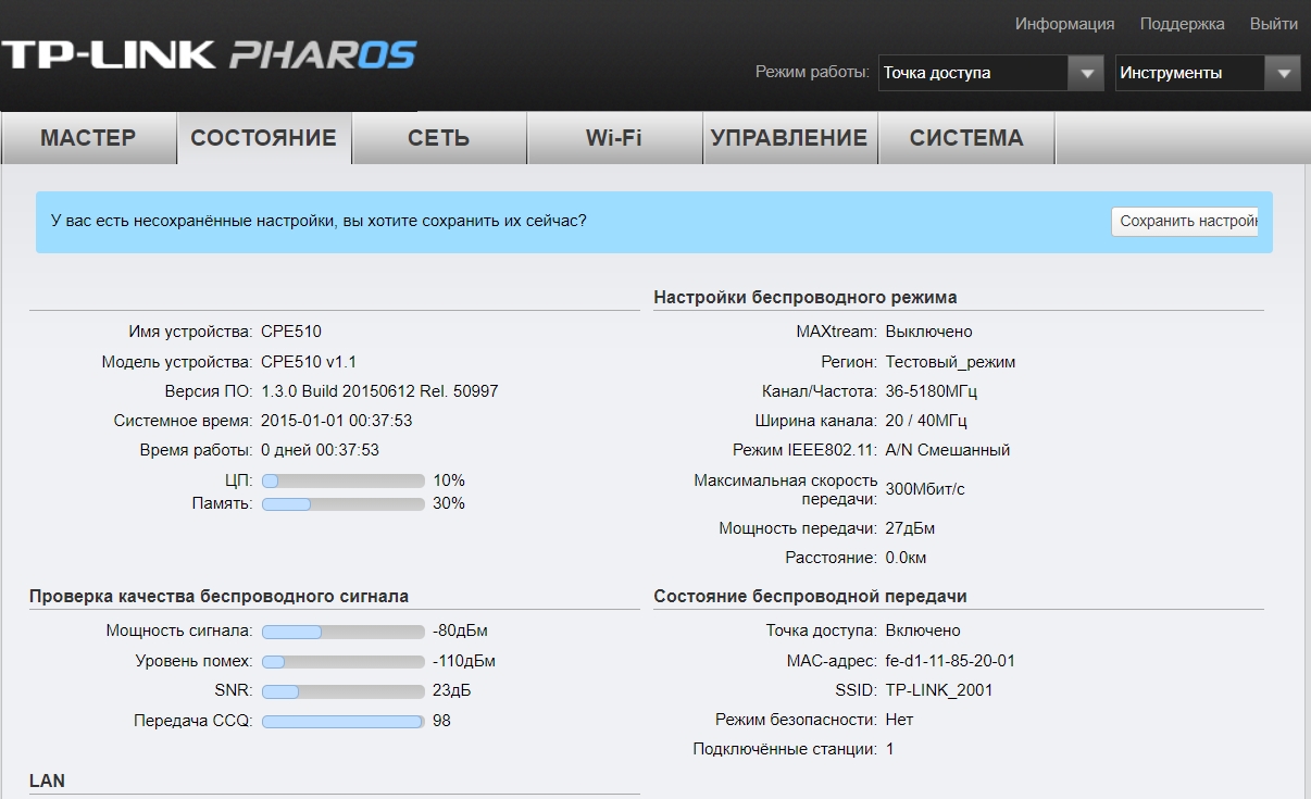
Откроется панель управления PHAR OS.

Дальше просто меняем режим работы точки доступа и настраиваем ее.
Настройка TP-Link CPE510 в режиме «Точка доступа»
В панели управления, в разделе «Мастер» выбрав режим «Точка доступа» нажимаем на кнопку «Далее».

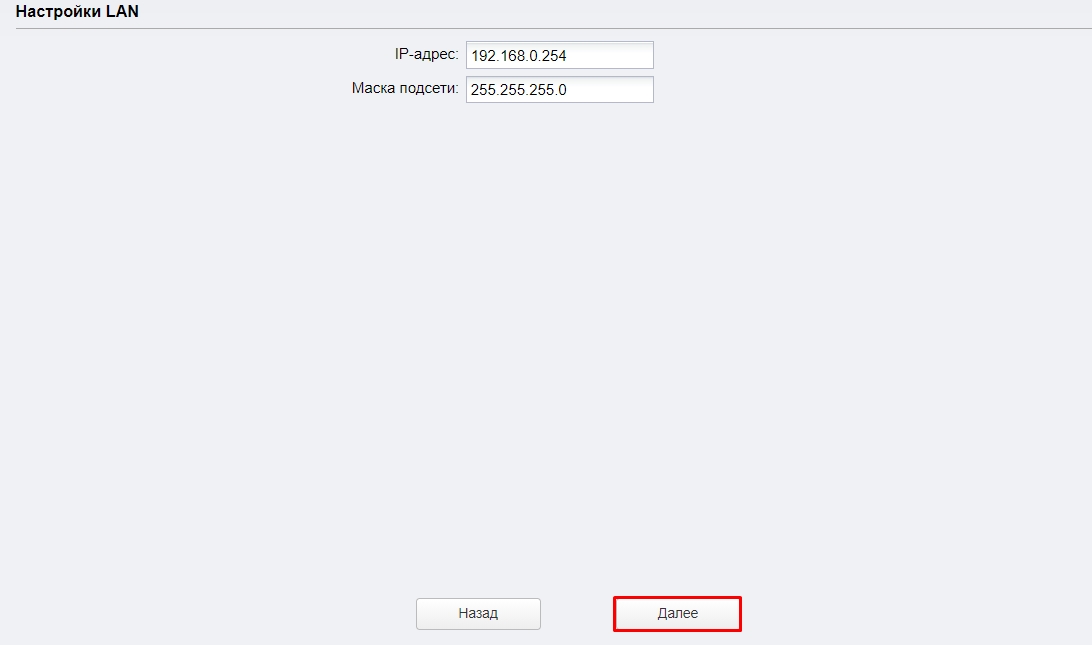
В настройках LAN ничего не меняем, просто нажимаем «Далее».
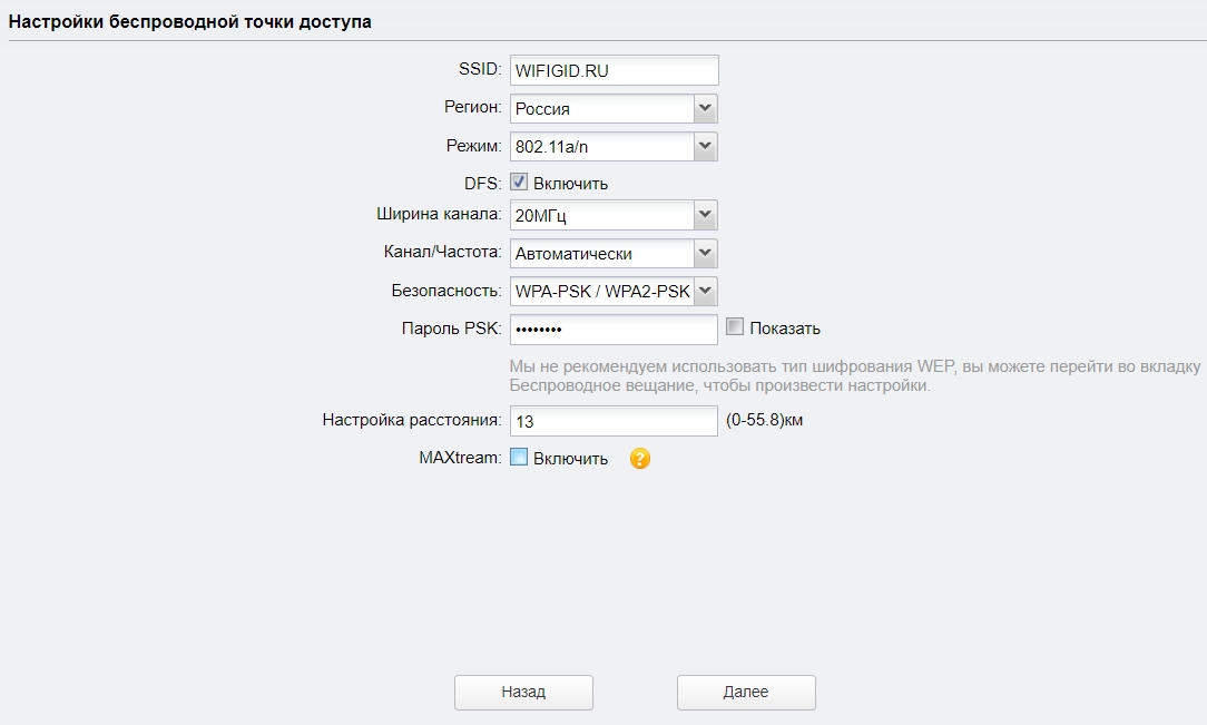
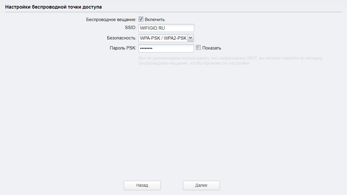
На следующем этапе нужно настроить беспроводную точку доступа. Сменить имя сети и другие параметры. Установить пароль, если необходимо.

Проверяем все параметры и нажимаем на кнопку «Завершить».
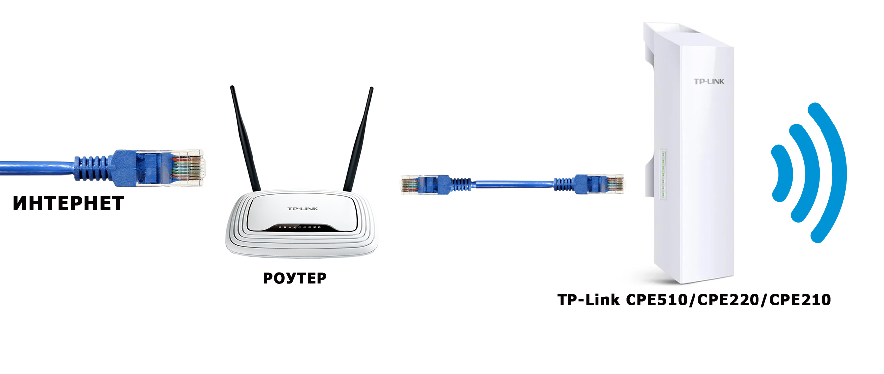
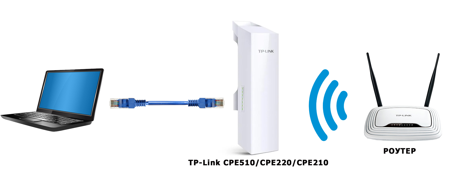
После сохранения настроек эту точку доступа можно отключить от компьютера. Установить ее на кронштейн (если она еще не установлена). Так как это точка доступа, то она будет передавать интернет. Значит его нужно подключить. Интернет подключаем от маршрутизатора (или другого устройства) в LAN порт на адаптере.
Получится примерно такая схема:

В настройках, в разделе «Wi-Fi» можно изменить разные параметры беспроводной сети. В том числе канал, мощность передатчика и т. д. Настроек там много. Так же советую поставить галочку возле пункта «Автоматически (Применить в 0-27.9км)».

Не забудьте сохранить настройки.
Режим работы «Клиент» (прием сигнала)
Вторую точку доступа (на втором конце) нужно настроить в режиме клиента. Перед настройкой ее нужно направить на источник сигнала (в нашем случае, это первая ТД). Подключаемся к ней, заходим в настройки и переключаемся в режим «Клиент».

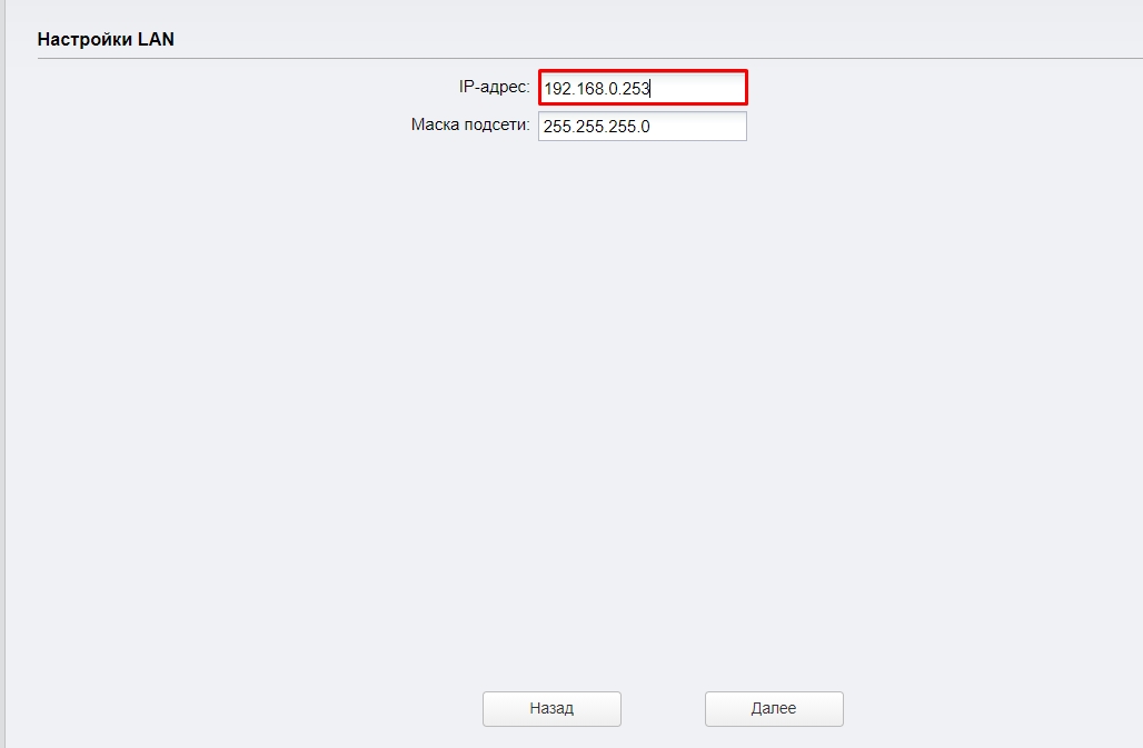
Меняем последнюю цифру IP-адреса. Чтобы он отличался от IP-адреса точки доступа.

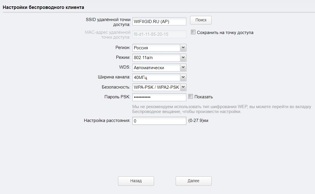
В следующем окне нажимаем на кнопку «Поиск». Из списка выбираем нашу точку доступа.

Если она защищена паролем, то вводим его и сохраняем настройки. Наша точка доступа в режиме клиента подключится к главной Wi-Fi сети. От клиента можно кабелем подключить интернет к маршрутизатору, или напрямую к компьютеру.
Всем привет на портале WiFiGid! Сегодня мы поговорим про одну из самых популярных точек доступа – модель TP-Link CPE510. В общем они все примерно одинаковые, поэтому данная статья подойдет и для пользователей других моделей: CPE520, CPE220 и CPE210. Они имеют одинаковую операционную систему PHAROS, подключаются и настраиваются одинаково. Есть пара отличий в характеристиках, но об этом чуть позже.
Брал я ее для раздачи интерната на большую территорию, но данные модели подойдут и для других вариантов использования. Я все описал максимально подробно. Так как данное устройство будет работать на улице, и есть вероятность удара молнии или короткого замыкания, то советую читать все очень внимательно от самого начала и до конца. Поехали!
Содержание
- Плюсы, минусы и мое мнение
- ШАГ 1: Распаковка и комплектация
- ШАГ 2: Порты и подключение
- ШАГ 4: Настройка
- Точка доступа
- Клиент/Ретранслятор (Усилитель)/ Мост
- Точка доступа с маршрутизатором
- Беспроводной клиент (WISP)
- ШАГ 5: Боевая установка
- Настройка DHCP
- Мульти SSID (Несколько Wi-Fi сетей)
- Фильтрация MAC-адресов
- Обновление прошивки
- Характеристики и сравнение с CPE220 и CPE210
- Эмулятор
- Руководство пользователя
- Видео
- Задать вопрос автору статьи
Плюсы, минусы и мое мнение
- Работает в разных режимах: точка доступа, клиент, повторитель, мост, обычный роутер, подключение к WISP. Про эти режимы я подробно расскажу ниже.
- Очень удобная и понятная прошивка. Если честно она мне понравилась даже больше, чем на обычных домашних роутерах.
- Прочный корпус из PBT пластика, а не из ABS.
- Режим защиты от влаги и пыли по стандарту IPX
- Есть регулировка мощности сигнала от 0 до 20 дБм (или 100 мВт).
- Поддержка MIMO 2х2.
- Две встроенные двухполяризационные антенны по 13 дБи.
- TP-LINK Pharos MAXtream TDMA – данный режим позволяет работать сразу с несколькими точками доступа.
- PoE питание и дополнительный обычный LAN порт.
- Поддержка 5 ГГц. Младшие модели CPE220 и CPE210 работают с 2,4 ГГц.
- Процессор Qualcomm Atheros с тактовой частотой 560 МГц позволяет отлично переваривать большое количество устройств.
- MAXtream TDMA – данный режим позволяет уменьшить конфликты большого количества точек доступа. Также это позволяет улучшить связь и пропускную способность сети. Запатентованная технология, которая работает только с TP-Link точками доступа. Но её можно отключить.
- Защита от ударов молний.
- Защита от электростатического разряда.
- Поддержки ширины канала в 5, 10, 20 и 40 МГц.
- Работает на расстоянии до 15 километров.
- Функция автоматической отправки журнала событий на почту.
- Есть возможность настроить мульти-SSID – несколько разделенных по VLAN вай-фай сетей.
- Дополнительные функции: Ping Watch Dog, DDNS, агент SNMP, подключение WEB-сервера, SSH-сервер, фильтрация MAC-адресов.
- Очень смешная цена у CPE
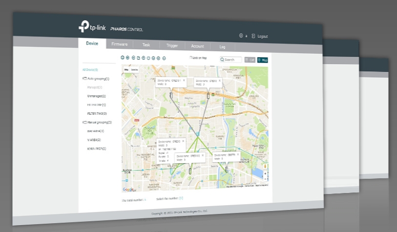
- Pharos Control – программа для управления несколькими точками.
- В режиме роутера не поддерживает L2TP и PPTP типы подключения.
- Нет фильтрации по URL.
Сразу скажу, что я точкой доступа очень доволен. Во-первых, она очень просто и легко подключается. Даже простой пользователь с легкостью её настроит. Во-вторых, внутри стоит очень удобный интерфейс. В-третьих, антенна действительно может покрыть достаточно большую территорию. Я её установил на кронштейн на базе, и она покрывает всю территорию. В-четвертых, брал её за 4200 рублей – согласитесь, даже роутеры стоят дороже. При подключении до 20 устройств, работает стабильно, не греется и не отваливается. Система позволяет мониторить большое количество данных и отправлять их на почту.
Если вы используете несколько точек доступа от TP-Link, то для удобства управления есть специальное приложение Pharos Control.
ШАГ 1: Распаковка и комплектация
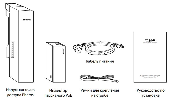
Итак, у в комплекте идет достаточно небольшая коробка. Давайте её распакуем и посмотрим, что же внутри:
- Само устройство.
- Блок питания
- Кабель питания.
- Стяжки.
- Гарантийный талон.
- Руководство пользователя.
И другие не очень важные бумажки. Корпус белый, сделанный из качественного пластика. Точка доступа может спокойно работать в уличных условиях. Корпус выполнен с защитой IPX5.
Снизу можно заметить специальные держатели, с помощью которых можно повесить устройство на кронштейн. Именно для этого в коробке есть стяжки. Устройство способно работать в самых экстремальных условиях от -40 до +70 градусов по Цельсию.

Как я понял, корпус сделан не из дешевого ABS пластика, который используется везде. А из прочного и стойкого PBT. Сбоку есть индикация:

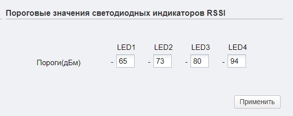
- Первые четыре лампочки – это индикация порога в дБм:
- 65 дБм.
- 73 дБм.
- 80 дБм
- 94 дБм
- LAN 0-1 – подключение к локальным портам.
- POWER – питания.
Порог индикации можно будет изменить в настройках, в разделе «Система», подраздел «Пороговые значения светодиодных индикаторов RSSI».
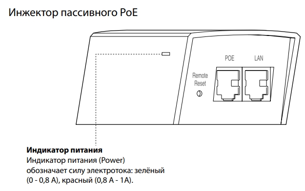
Если посмотреть на инжектор, то можно также увидеть индикатор питания, который может гореть и обозначать силу электротока:
- Зеленый (0-0,8А).
- Красный (0,8-1А).
ШАГ 2: Порты и подключение
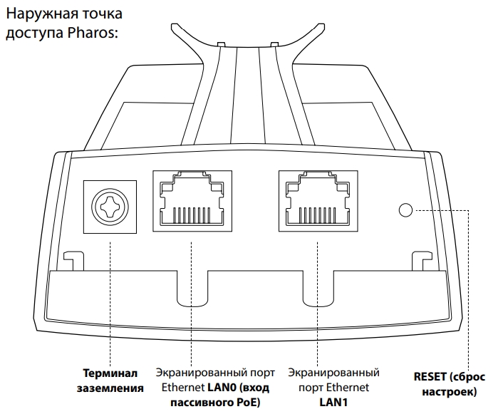
Давайте рассмотрим все порты на точке доступа и сразу её подключим. Снизу мы можем увидеть:
- Терминал заземления
- LAN порт с пассивным питанием PoE.
- Обычные LAN порт.
- Reset – кнопка для сброса точки доступа до заводской конфигурации. Для этого её нужно зажать на 10 секунд при включенном устройстве.
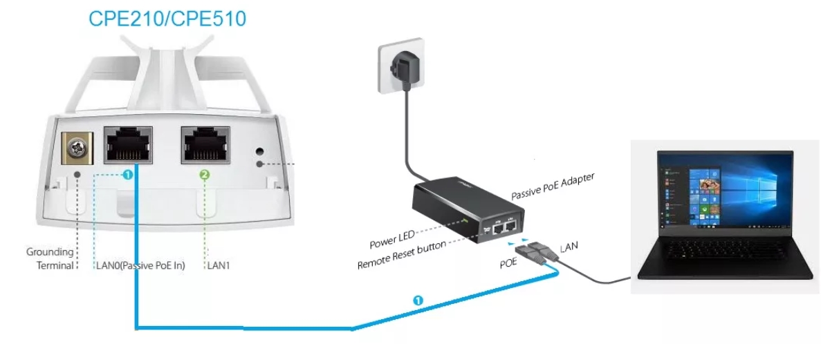
Для настройки вам нужно будет подключить ноутбук или компьютер к точке доступа по схеме выше. Для этого вам понадобятся два сетевых Ethernet кабеля. Один подключаем от «PoE In» точки доступа к аналогичному PoE блока питания. Второй кабель просто подключаем к ноутбуку.
Обычно данное устройство настраивают в двух режимах: точка доступа и клиент. То есть одно раздает Wi-Fi, а второе к нему подключается. Можно использовать вообще один аппарат, а подключаться к вай-фай с роутеров, телефонов, ноутбуков или других устройств. Отлично подойдет для раздачи интернета в промышленных зонах, на складах и в крупных предприятиях.
По умолчанию в прошивке не включен DHCP, поэтому для входа в настройки устройства нужно будет прописать статический IP в сетевой конфигурации ноутбука или компьютера.
- Нажмите одновременно на клавиши «Win» и «R» и введите команду:
ncpa.cpl
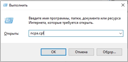
- Откройте свойства Ethernet подключения.
- Нажмите один раз по IPv4 и зайдите в «Свойства». Далее установите галочку для ручной конфигурации. Вводим значения:
- IP-адрес – 192.168.0.2
- Маска подсети – 255.255.255.0 (Установится автоматический)
- Основной шлюз – 192.168.0.254
ШАГ 4: Настройка
- Теперь открываем браузер и в адресную строку вводим адрес точки доступа:
192.168.0.254
ПРИМЕЧАНИЕ! Если будут проблемы с входом, то добавьте в начало строки «http://», чтобы получилось так – http://192.168.0.254
- Вас также попросят ввести:
- Логин – admin
- Пароль – admin
- Выберите регион, а также язык. Обязательно выделите галочку ниже и нажмите по кнопке «Login».
- После этого язык панели изменится на русский, и вам будет предложено изменить пароль от админки.
- Мы попадем на вкладку «Состояния», чтобы приступить к настройке нажмите по первому разделу «МАСТЕР».
Далее вы увидите несколько режимов, в которых может работать наше устройство. Давайте поподробнее разберем каждый, а вы уже на примере сможете выбрать тот, который нужен именно вам.
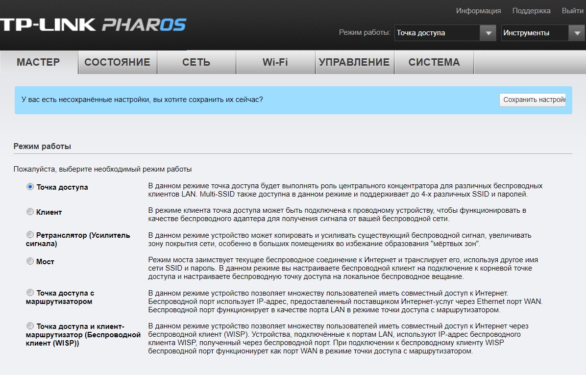
Точка доступа
Для подключения к интернету мы будем использовать основной маршрутизатор, к которому и будет подключен интернет. Далее от LAN порт роутера идет подключение к тому же порту на TP-Link CPE510. И уже точка доступа будет раздавать Wi-Fi на другие устройства. Все настройки DHCP будет раздавать роутер, а не точка доступа.
Когда вы выберите этот пункт, вам предложат изменить IP адрес устройства – оставляем значение как есть и переходим к следующему шагу.
Теперь давайте пройдемся по настройкам:
- SSID – имя вай-фай сети.
- Регион – установите ваш регион.
- Режим – оставляем значение по умолчанию.
- DFS – включаем.
- Ширину канала – ставим 20/40 или 20 МГц.
- Канал/Частота – Автоматически.
- Безопасность – WPA-PSK / WPA2-PSK.
- Пароль PSK – вводим ключ от вайфай.
- Настройка расстояния – если вы не знаете точное расстояние, то установите значение 0.
- MAXtream – как я понял, это собственная разработка от TP-Link, которая увеличивает расстояние работы беспроводной сети. Проблема всех этих разработок, что они могут криво работать со сторонними устройствами, так что я бы её выключил. Но ради теста, можете попробовать – если будут проблемы с подключением, то выключите.
Клиент/Ретранслятор (Усилитель)/ Мост
В режиме «Клиента» точка доступа подключается к сторонней Wi-Fi сети роутера, а раздает его по проводу. К проводу можно подключить не только одно устройство (компьютер или ноутбук), но и другой роутер. Роутер должен быть подключен к WAN порту, а в настройках интернет подключения (WAN) выбрать DHCP (Динамический IP).
В режиме «Ретранслятор (Усилитель сигнала)» точка доступа подключается к роутеру или другой точке доступа и усиливает сигнал в данной области, полностью копируя данную Wi-Fi сеть. Режим «Моста» повторяет то же самое подключение, но есть одно отличие – в таком режиме точка доступа будет раздавать самостоятельную Wi-Fi сеть.
Если вы используете в качестве основной точки доступа такую же модель (TP-Link CPE510/CPE220/CPE210/CPE520), то вам нужно изменить IP-адрес и поменять одну цифру. То есть будет так:
- Точка доступа – 192.168.0.254
- Клиент – 192.168.0.253
Если вы будете подключаться к Wi-Fi роутера или другого подобного устройства, то вам нужно узнать IP-адрес этого аппарата и сделать аналогичные действия – установить такой же IP, но изменить последнюю цифру. Также в роутере зайдите в раздел LAN-клиентов и установите статический, зарезервированный адрес для этой точки доступа в режиме клиента.
СОВЕТ! Если будут проблемы с коннектом, то после настройки перейдите в раздел «Сеть» и установите «Тип подключения» в «Динамический» режим. То есть данная точка доступа будет получать IP от другого устройства. На нем должен быть включен DHCP-сервер.
На следующем этапе нам нужно подключиться к вай-фай – для этого жмем по кнопке «Поиск». Находим нашу сеть, и вводим «Пароль PSK». Для первичной настройки держите оба устройства на расстоянии не более 5 метров.
Если вы используете режим моста, то нам нужно ввести самостоятельные настройки Wi-Fi сети с именем и паролем. Можно также вообще выключить вещание, тогда интернет будет раздаваться только по проводу.
Точка доступа с маршрутизатором
В данном режиме TP-Link CPE510 работает как обычный роутер – подключается к кабелю провайдера и раздает интернет по вай-фай.
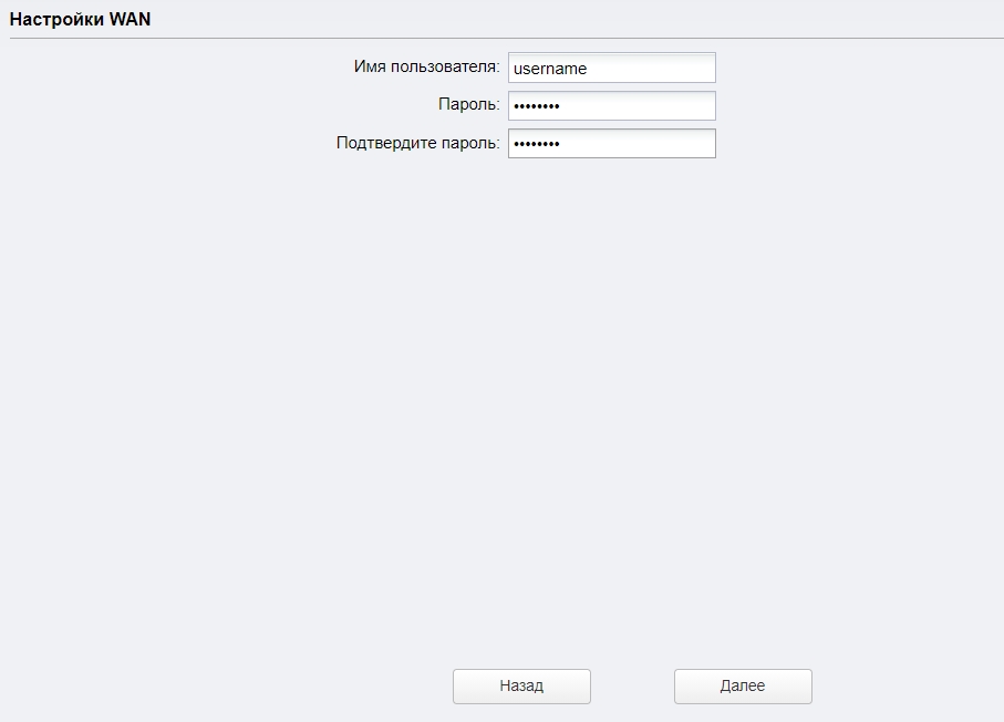
Как видите, аппарат поддерживает только три типа подключения: динамический, статический IP и PPPoE. Берем договор от провайдера, где указаны определённые данные, которые нужны для коннекта к интернету.
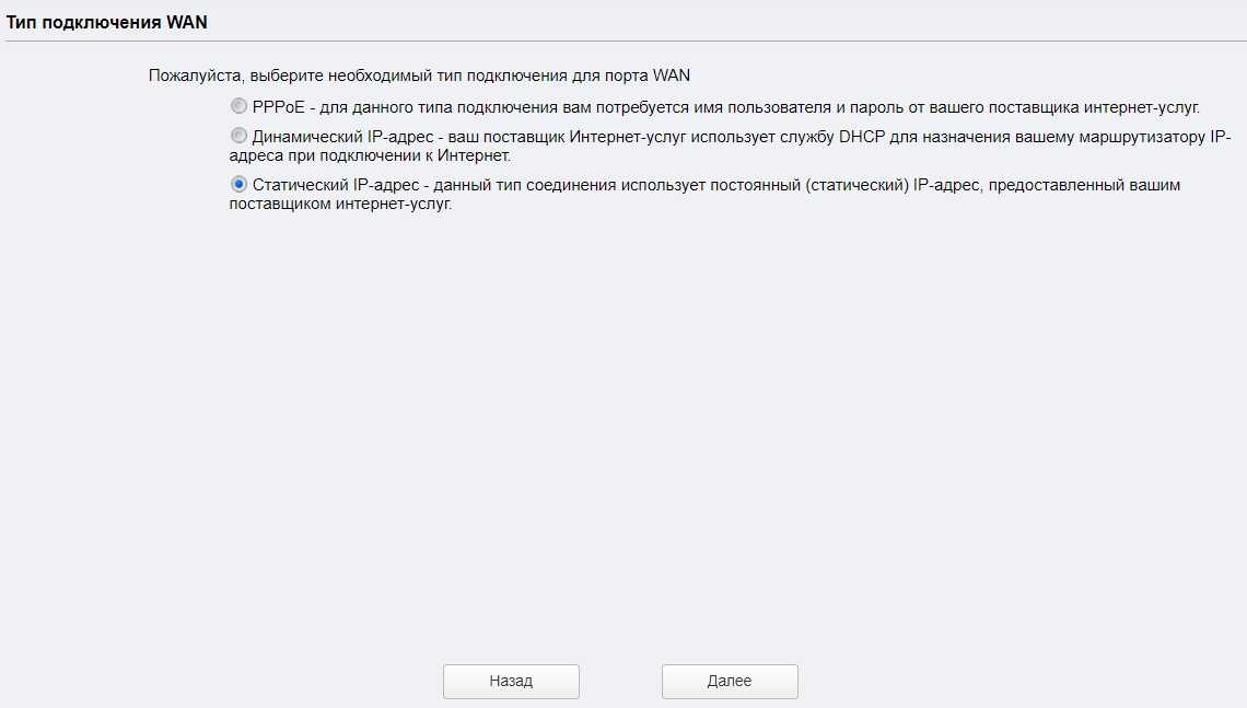
Вводим эти данные.
В конце останется настроить вай-фай. Ставим настройки как на картинке ниже.
Беспроводной клиент (WISP)
В данном подключении точка доступа подключается к WISP-антенне провайдера и уже потом раздает вай-фай на свои устройства.
Для подключения к интернету нужно будет указать тип подключения и ввести данные. Если в договоре по этому поводу ничего нет, то указываем «Динамический IP-адрес».
С помощью «Поиска» подключаемся к сети провайдера, введя пароль.
И в самом конце вводим настройки своей локальной Wi-Fi сети, которую вы будете использовать. Интернет также будет раздаваться по LAN портам.
ШАГ 5: Боевая установка
Все прошлые манипуляции мы выполняли в домашних условиях. Теперь я расскажу про подключение точки доступа в боевых. Смотрите, оба порта на устройстве экранированы, и не просто так.
Для установки нам понадобится кронштейн. Если вы используете две точки доступа, то вам нужно установить их так, чтобы они были четко направлены друг на друга. Особенно это касается режима моста, повторителя, клиента. Лучше устанавливать максимально высоко таким образом, чтобы на пути радиоволны было как можно меньше препятствий. Напоминаю, что любые препятствия глушат сигнал. Особенно это касается толстых стен и металлических преград.
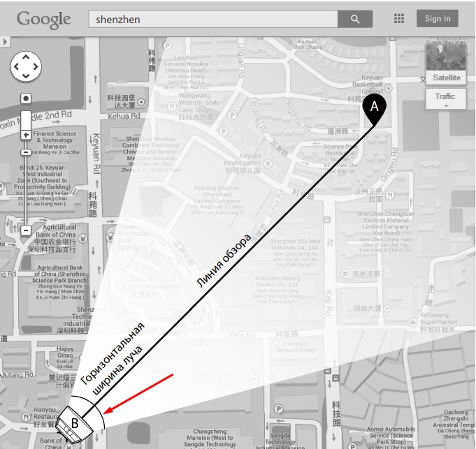
Так как у разных моделей CPE разный показатель коэффициента усиления, то и размер луча разный.
| CPE210 | CPE220 | CPE510 | CPE520 | |
| Горизонтальная ширина (в градусах) | 70 | 45 | 45 | 50 |
Подключение аналогичное, как мы и делали все в самом начале, но будут пару отступлений.
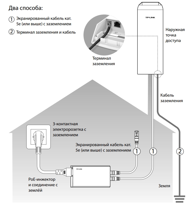
Для подключения к LAN0 от POE In нужно использовать кабель с заземлением категории 5E или выше. Также желательно, чтобы он был экранированным. Но земля будет работать только в том случае, если инжектор подключен к розетке с землей.
На кронштейн антенну можно прикрутить стяжками. После подключения к антенне обязательно закройте нижнюю часть с портами специальной крышкой. Кабель питания должен быть не больше 60 метров.
Но есть и второй способ – подключить обычный кабель и использовать провод заземления, подключив его от терминала заземления к основной земле.
Настройка DHCP
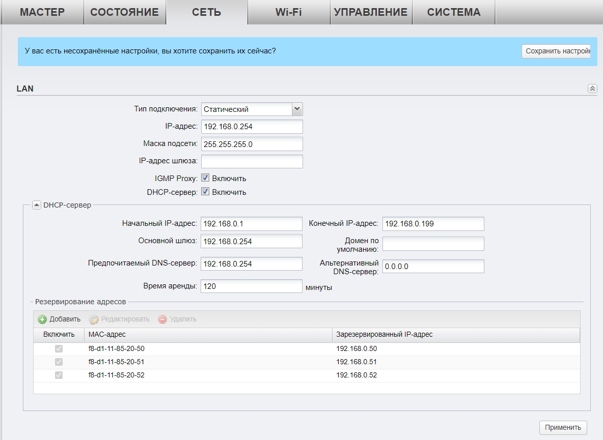
В разделе «Сеть» можно более детально установить IP-адрес устройства. Если вы подключаетесь к основному роутеру, или другой точке доступа с включенным DHCP-сервером, то можно в типе подключения установить «Динамическое» получение IP.
В режиме клиента, ретранслятора (усилителя) или Моста можно будет вручную ввести IP, маску и шлюз. Тут также можно включить DHCP-сервер для своих устройств. В режиме усилителя его включать не стоит. Ниже можно зарезервировать IP-адреса для локальных устройств.
Мульти SSID (Несколько Wi-Fi сетей)
Если у вас большое предприятие, то вы в теории можете разделить несколько отделов, подключив их к разным Wi-Fi сетям.
- Для этого переходим в «Wi-Fi».
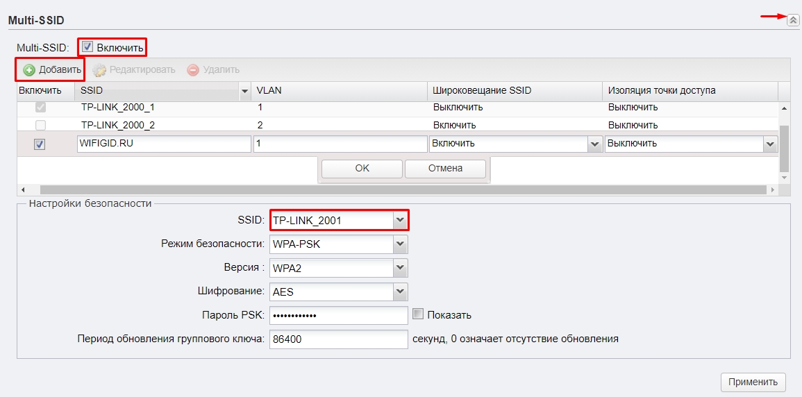
- Включаем «Multi-SSID».
- Нажимаем по кнопке «Добавить».
- Вводим название в поле «SSID». Указываем номер VLAN – разные VLAN это как бы разные сети, которые не могут контактировать друг с другом. Широковещание «SSID» – это видимость сети в эфире. Если выключить эту функцию, то сеть станет невидимой, а подключаться к ней нужно будет вручную, вводя имя и пароль. Изоляция точки доступа – это функция, которая изолирует клиентов друг от друга, то есть они не видят друг друга в сети. Эта функция нужна для открытых точек доступа, чтобы избежать взлома одного клиента другим.
- Нажимаем «ОК».
- Ниже выбираем «SSID». Указываем режим безопасности, версию, тип шифрования и вводим пароль.
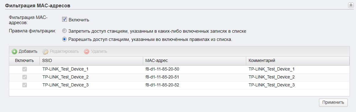
Фильтрация MAC-адресов
Также находится в разделе «Wi-Fi». Позволяет создать белый или черный список устройств, которым можно или запрещено подключаться к беспроводной сети. Максимально увеличивает безопасность, так как по определенным правилам сторонние устройства, даже зная пароль, не смогут подключиться к сети.
Обновление прошивки
ВНИМАНИЕ! Обновлять прошивку можно только при подключении по проводу.
- Заходим на официальную страницу аппарат.
- Выбираем свою аппаратную версию – её можно подсмотреть на этикетке на корпусе.
- Нажимаем по разделу «Встроенное ПО».
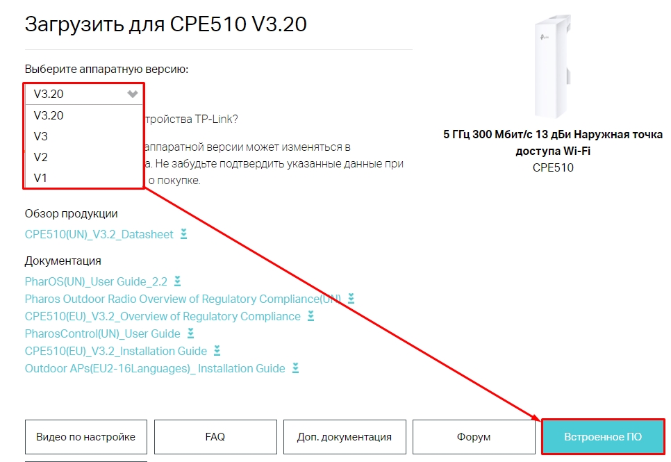
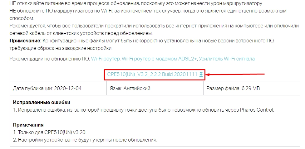
- Пролистываем ниже и скачиваем самую свежую прошивку.
- Переходим в «Систему», листаем до подраздела «Обновление встроенного ПО», нажимаем «Обзор», выбираем файл с прошивкой. Если вы до этого скачали архив, то обязательно его разархивируйте.
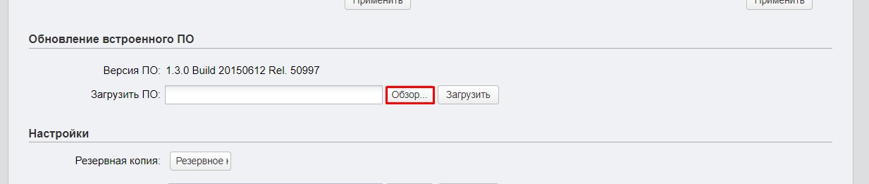
- Кликаем по кнопке «Загрузить» и ждем.
Характеристики и сравнение с CPE220 и CPE210
| CPE510 | CPE220 | CPE210 | |
| MIMO | 2х2 | ||
| Мощность (дБи) | 13 | 12 | 9 |
| Антенна (дБи) | 13 | 12 | 9 |
| Dual Ethernet | нет | есть | нет |
| Частота | 5 ГГц | 2,4 ГГц | |
| Максимальная скорость | До 300 Мбит в секунду | ||
| Ширина канала | 5/10/20/40 МГц | ||
| Питание | Passive PoE 24 В | ||
| Защита от статического удара | 15 кВ | ||
| Защита от ударов молнии | 6 кВ | ||
| Заземление | есть |
Эмулятор
Ссылка на эмуляторы
Руководство пользователя
Видео

User Guide
For TP-Link Pharos Series Products
CPE210 / CPE220 / CPE510 / CPE520 / CPE610
WBS210 / WBS510
1910012510 REV 3.0.2
December 2018

CONTENTS
About this User Guide …………………………………………………………………………………………… 1
Overview ………………………………………………………………………………………………………………… 2
1 Operation Modes …………………………………………………………………………………………….. 3
1.1 Access Point ……………………………………………………………………………………………………………………………… 4
1.2 Client …………………………………………………………………………………………………………………………………………… 5
1.3 Repeater (Range Extender) …………………………………………………………………………………………………….. 6
1.4 Bridge …………………………………………………………………………………………………………………………………………. 7
1.5 AP Router …………………………………………………………………………………………………………………………………… 7
1.6 AP Client Router (WISP Client) ……………………………………………………………………………………………….. 8
2 Quick Start ……………………………………………………………………………………………………….. 9
2.1 Check the System Requirements …………………………………………………………………………………………10
2.2 Log In to the Device ………………………………………………………………………………………………………………..10
2.3 Set Up the Wireless Network …………………………………………………………………………………………………11
Access Point ……………………………………………………………………………………………………………………………….. 12
Client …………………………………………………………………………………………………………………………………………… 16
Repeater (Range Extender) ………………………………………………………………………………………………………. 19
Bridge …………………………………………………………………………………………………………………………………………… 23
AP Router …………………………………………………………………………………………………………………………………….. 27
AP Client Router (WISP Client) …………………………………………………………………………………………………. 32
3 Monitor the Network ……………………………………………………………………………………..38
3.1 View the Device Information ………………………………………………………………………………………………….39
3.2 View the Wireless Settings …………………………………………………………………………………………………….39
3.3 View Wireless Signal Quality………………………………………………………………………………………………….40
3.4 View Radio Status ……………………………………………………………………………………………………………………41
3.5 View the LAN Settings …………………………………………………………………………………………………………….43
3.6 View the WAN Settings …………………………………………………………………………………………………………..43

3.7 Monitor Throughput ………………………………………………………………………………………………………………..44
3.8 Monitor Stations ………………………………………………………………………………………………………………………44
3.9 Monitor Interfaces …………………………………………………………………………………………………………………..45
3.10 Monitor ARP Table …………………………………………………………………………………………………………………..46
3.11 Monitor Routes ………………………………………………………………………………………………………………………..46
3.12 Monitor DHCP Clients ……………………………………………………………………………………………………………..47
3.13 Monitor Dynamic WAN ……………………………………………………………………………………………………………47
4 Configure the Network …………………………………………………………………………………. 49
4.1 Configure WAN Parameters …………………………………………………………………………………………………..50
4.2 Configure LAN Parameters ……………………………………………………………………………………………………57
Access Point/Client/Repeater/Bridge Mode …………………………………………………………………………. 57
AP Router/AP Client Router Mode …………………………………………………………………………………………… 60
4.3 Configure Management VLAN ………………………………………………………………………………………………62
4.4 Configure the Forwarding Feature ……………………………………………………………………………………….62
4.5 Configure the Security Feature …………………………………………………………………………………………….66
4.6 Configure Access Control ……………………………………………………………………………………………………..69
4.7 Configure Static Routing ………………………………………………………………………………………………………..70
4.8 Configure Bandwidth Control ………………………………………………………………………………………………..71
4.9 Configure IP & MAC Binding …………………………………………………………………………………………………..73
5 Configure the Wireless Parameters …………………………………………………………… 75
5.1 Configure Basic Wireless Parameters …………………………………………………………………………………76
5.2 Configure Wireless Client Parameters ………………………………………………………………………………..78
5.3 Configure Wireless AP Parameters ………………………………………………………………………………………82
5.4 Configure Multi-SSID ………………………………………………………………………………………………………………88
5.5 Configure Wireless MAC Filtering ………………………………………………………………………………………..90
5.6 Configure Advanced Wireless Parameters …………………………………………………………………………91
6 Manage the Device ……………………………………………………………………………………….. 94
6.1 Manage System Logs ……………………………………………………………………………………………………………..95

6.2 Specify the Miscellaneous Parameters ……………………………………………………………………………….96
6.3 Configure Ping Watch Dog …………………………………………………………………………………………………….97
6.4 Configure Dynamic DNS …………………………………………………………………………………………………………98
6.5 Configure Web Server…………………………………………………………………………………………………………….99
6.6 Configure SNMP Agent ……………………………………………………………………………………………………….. 100
6.7 Configure SSH Server …………………………………………………………………………………………………………. 102
6.8 Configure RSSI LED Thresholds ………………………………………………………………………………………… 102
7 Configure the System ………………………………………………………………………………… 104
7.1 Configure Device Information ……………………………………………………………………………………………. 105
7.2 Configure Location Information ………………………………………………………………………………………… 105
7.3 Configure User Account ……………………………………………………………………………………………………… 105
7.4 Configure Time Settings …………………………………………………………………………………………………….. 106
7.5 Update Firmware ………………………………………………………………………………………………………………….. 108
7.6 Configure Other Settings ……………………………………………………………………………………………………. 109
8 Use the System Tools ………………………………………………………………………………… 110
8.1 Configure Ping ……………………………………………………………………………………………………………………… 111
8.2 Configure Traceroute ………………………………………………………………………………………………………….. 111
8.3 Test Speed ……………………………………………………………………………………………………………………………. 112
8.4 Survey ……………………………………………………………………………………………………………………………………. 113
8.5 Analyze Spectrum ………………………………………………………………………………………………………………… 115

About this User Guide
This User Guide contains information for setup and management of TP-Link Pharos series
products. Please read this guide carefully before operation.
When using this guide, please notice that features of the product may vary slightly depending on
the model and software version you have, and on your location, language, and internet service
provider. All screenshots, images, parameters and descriptions documented in this guide are used
for demonstration only.
Some models featured in this guide may be unavailable in your country or region. For local sales
information, visit
The information in this document is subject to change without notice. Every effort has been made
in the preparation of this document to ensure the accuracy of the contents, but all statements,
information, and recommendations in this document do not constitute the warranty of any kind,
express or implied. Users must take full responsibility for their application of any products.
http://www.tp-link.com
.
Convention
Unless otherwise noted, the introduction in this guide takes CPE510 as an example.
More Info
The latest software, management app and utility can be found at Download Center at
https://www.tp-link.com/support
The Quick Installation Guide can be found where you find this guide or inside the package of the
product.
Specifications can be found on the product page at
.
https://www.tp-link.com
.
Our Technical Support contact information can be found at the Contact Technical Support page at
https://www.tp-link.com/support
To ask questions, find answers, and communicate with TP-Link users or engineers, please visit
https://community.tp-link.com
.
to join TP-Link Community.
1

Overview
is TP-Link’s next generation outdoor product series dedicated to long-distance
outdoor wireless networking solutions.
is a powerful Web-based operating system, which is integrated into all Pharos series
products.
New features of Pharos series products are listed as follows:
• Provides User-friendly UI design.
• TP-Link Pharos MAXtream (Time-Division-Multiple-Access) technology improves product
performance in throughput, capacity and latency, which are ideal for point-to-multipoint
applications.
• Supports multiple operation modes: Access Point, Client, Repeater (Range Extender), Bridge, AP
Router and AP Client Router (WISP Client).
• Provides system-level optimization for long-distance wireless transmission.
• Supports selectable bandwidth of 5/10/20/40MHz.
• Supports easy antenna alignment with Wireless Signal Indicators on Web interface.
• Provides Throughput Monitor, Spectrum Analyzer, Speed Test and Ping tools.
• Supports discovery and management via Pharos Control application.
2

1
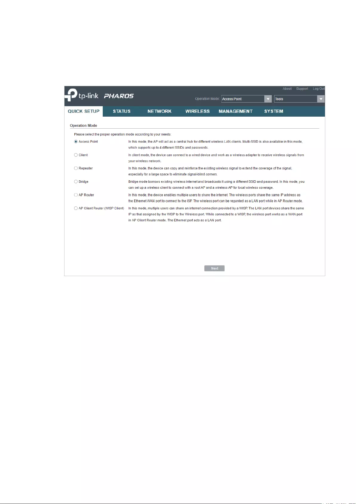
The Pharos series products support six operation modes to satisfy user’s diversified
network requirements. This chapter introduces typical usage scenarios of different
modes, including:
1.1 Access Point
1.2 Client
1.3 Repeater (Range Extender)
1.4 Bridge
1.5 AP Router
1.6 AP Client Router (WISP Client)
Operation Modes
3

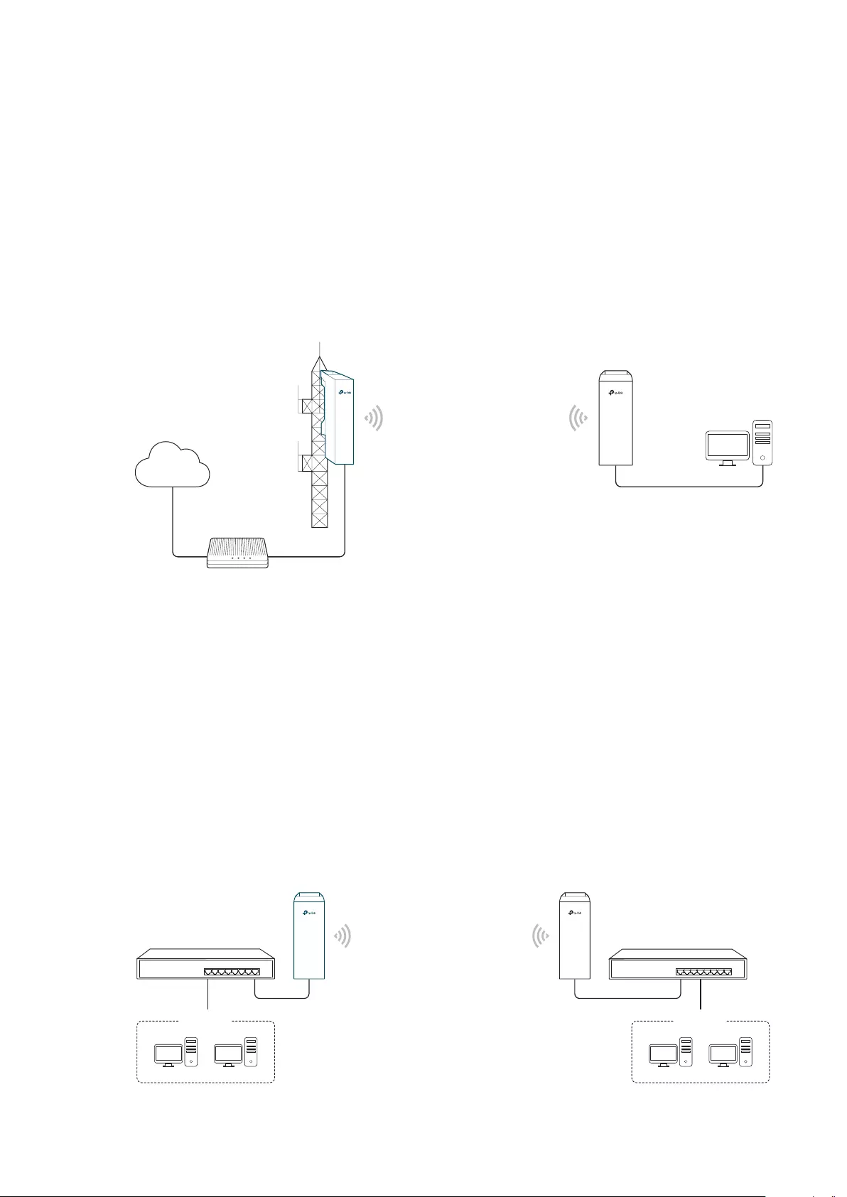
1.1 Access Point
In AP mode, the device acts as a central hub and provides wireless access point for
wireless clients, thus the AP mode is applicable to the following three scenarios.
Meanwhile, Multi-SSID function can be enabled in this mode, providing up to four wireless
networks with different SSIDs and passwords.
Scenario 1
Access Point
LAN: 192.168.7.2
Internet
Router
LAN: 192.168.7.1
AP Client Router
LAN: 192.168.0.254
WAN: Dynamic IP
Network requirements: Establish the network coverage in the remote areas without long-
distance cabling.
The device in the network: In the adjacent town covered by wired network, ISP (Internet
Service Provider) can put up a device in AP mode to access the internet and transform
wired signal into wireless one. In the remote area, users can put up a device in AP Client
Router mode to access the wireless network.
Advantages: Transmit data wirelessly across a long distance and reduce the cabling cost.
Scenario 2
Access Point Client
LAN: 192.168.0.254 LAN: 192.168.0.2
Switch
Oce Oce
4
Switch
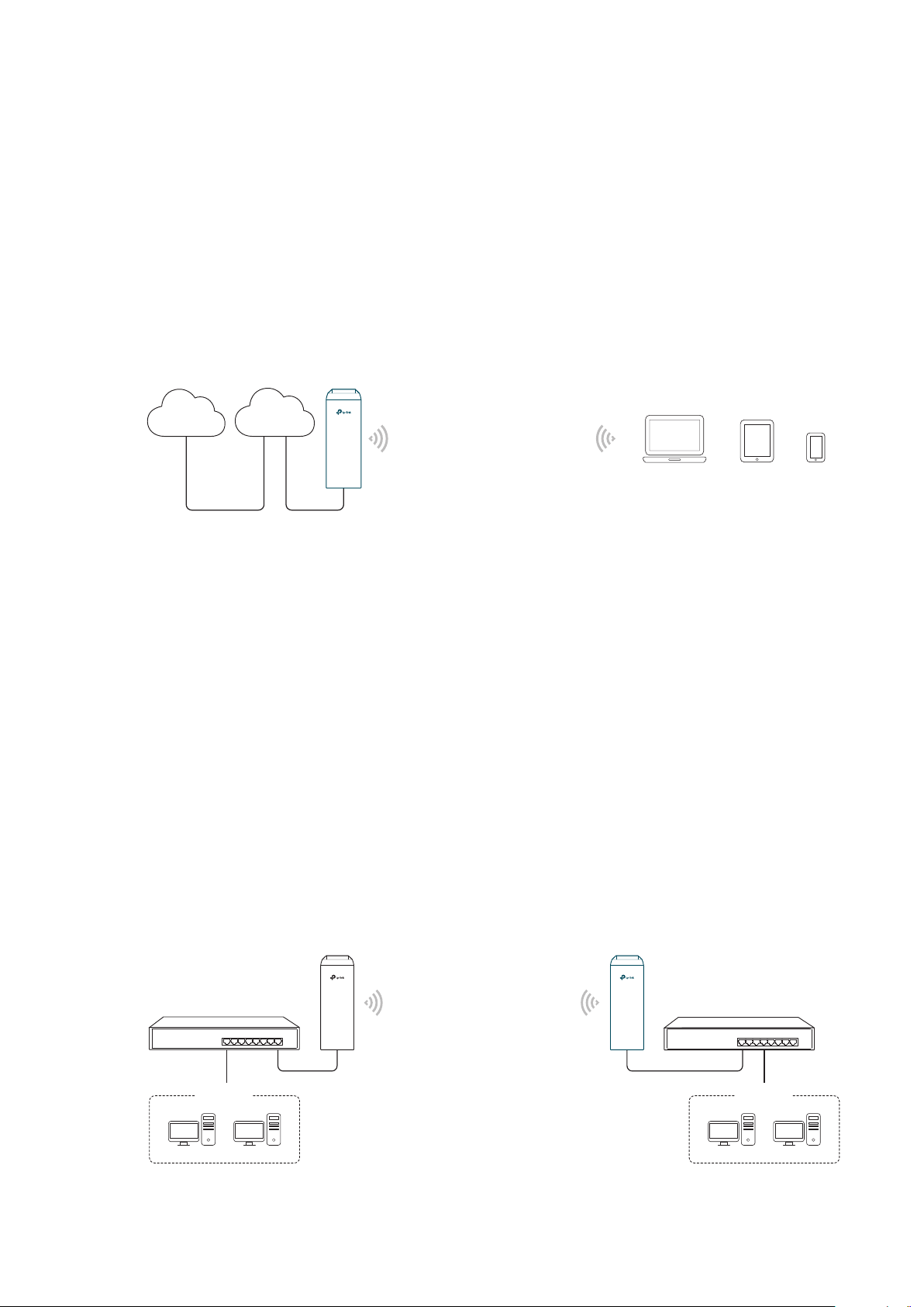
Network requirements: Combine two separate office networks into one.
The device in the network: The device in AP mode connects to one office network
and creates a wireless network. The device in Client mode connects to the other office
network and the wireless network.
Advantages: Establish a point-to-point WLAN across a long distance to achieve the
connectivity between two networks and avoid the cabling trouble.
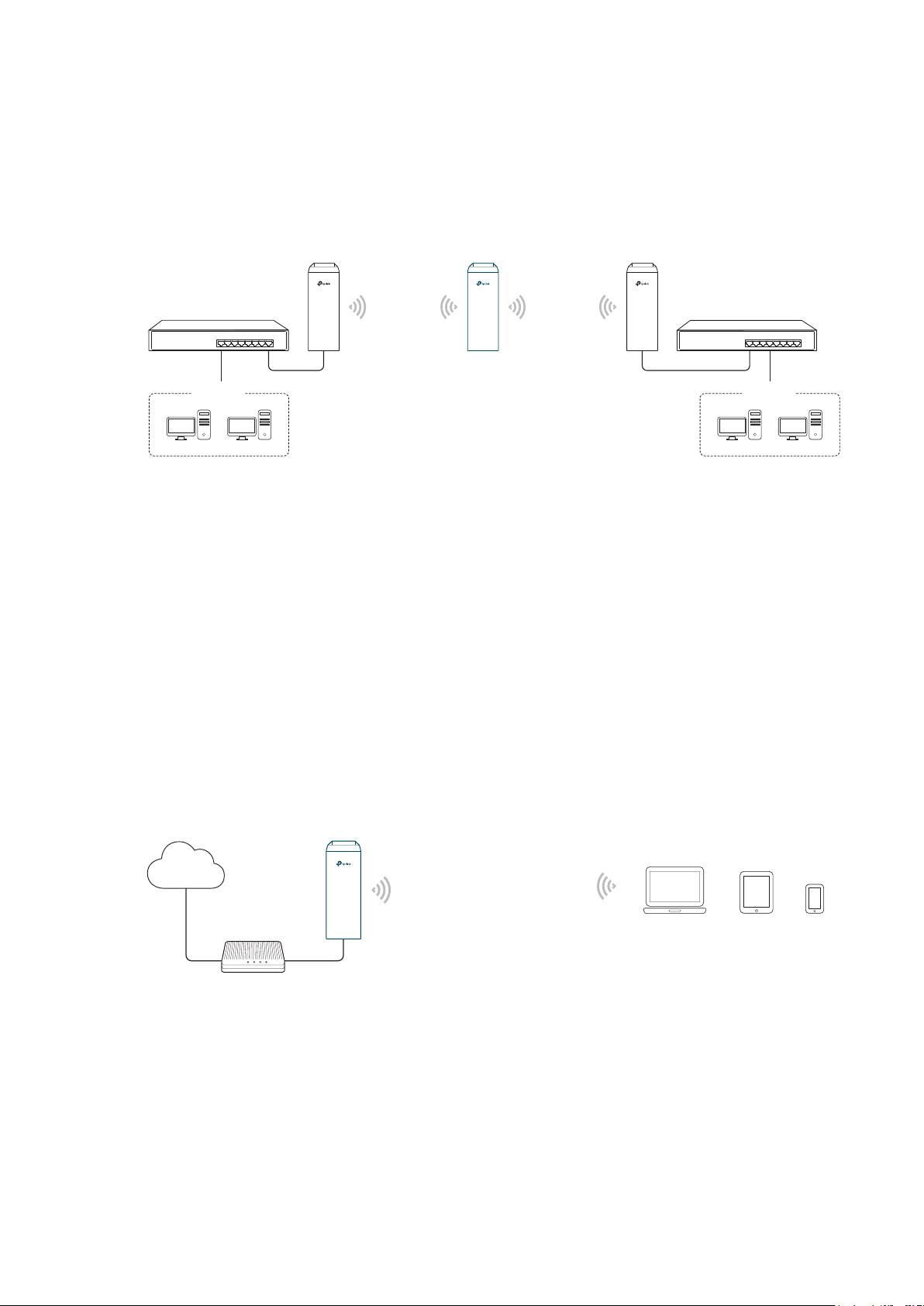
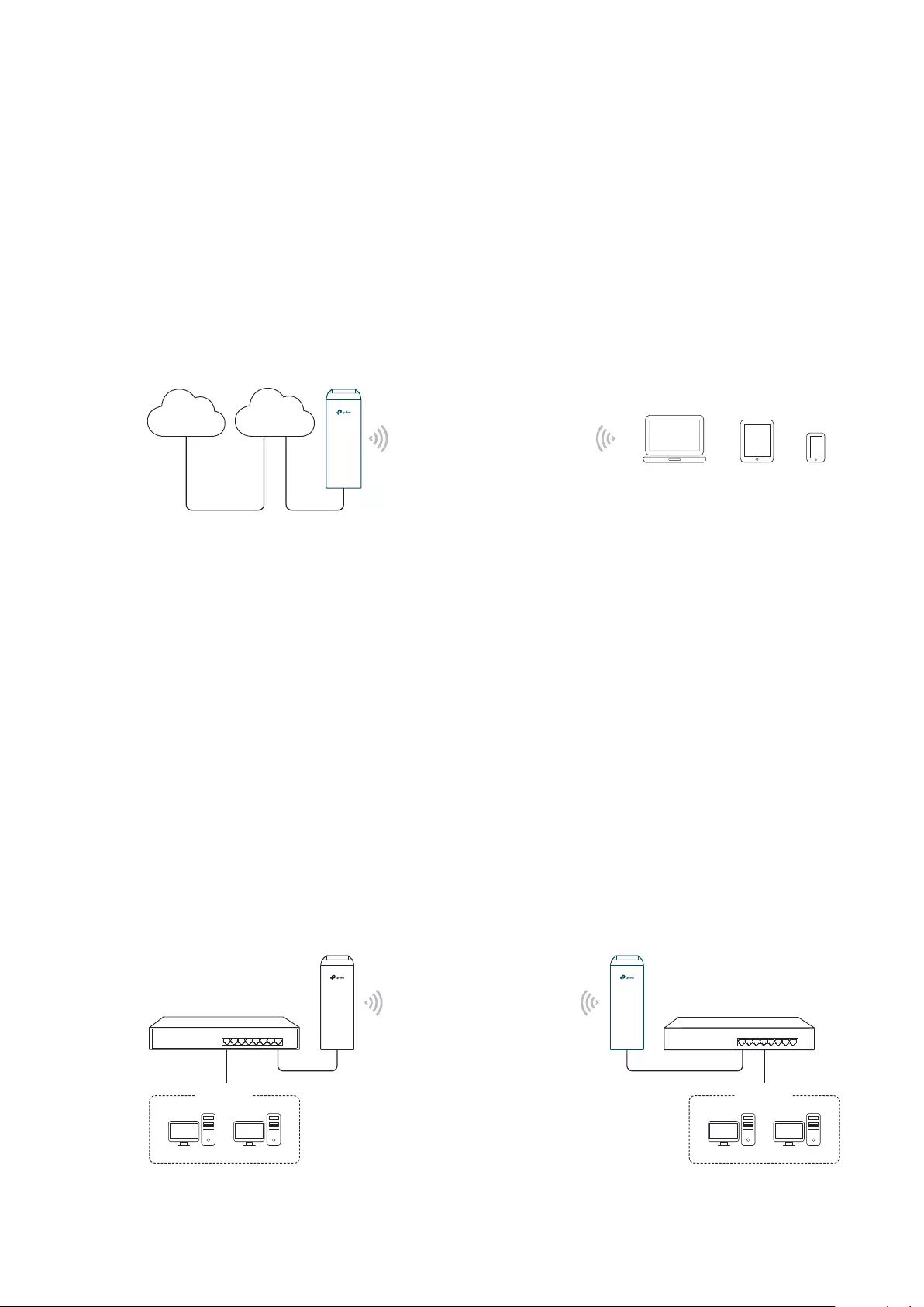
Scenario 3
Internet
Network requirements: Establish wireless network coverage in the campus, community,
industrial park or public place to provide wireless access for users.
The device in the network: With the access to campus wired network or other wired local
area networks, the device in AP mode provides the wireless access for wireless clients,
such as smart phones, laptops and tablets to connect to the network.
Advantages: Enrich the access ways of local area network and extend the network
coverage.
1.2 Client
Wired Local
Area Network
Access Point
Laptop/Tablet/Smartphone
For the device in Client mode, the most common usage scenario is point-to-point
networking. The device is used to transform wireless signal into wired one.
Access Point
LAN: 192.168.0.254
Switch
Oce Oce
5
Client
LAN: 192.168.0.2
Switch
Network requirements: Help the wired devices to connect to the wireless network.
The device in the network: In Client mode, the device actually serves as a wireless adapter
to receive the wireless signal from root AP or Station. In this case, wired devices can
access the wireless network by connecting to the device in Client mode.
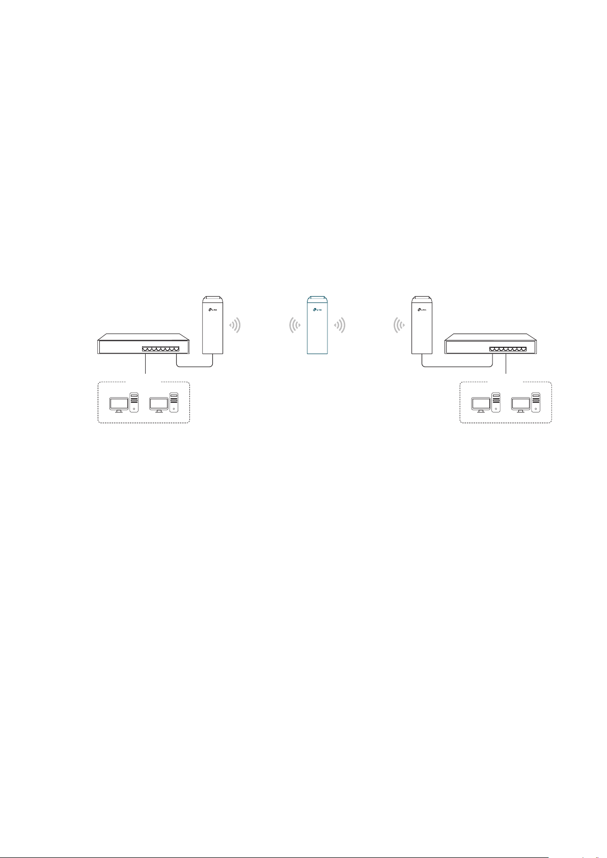
1.3 Repeater (Range Extender)
The device in Repeater mode can extend wireless coverage of an existing wireless
network. The SSID and encryption type of the device should be the same as those of the
root AP.
Access Point Client
LAN: 192.168.0.254
Switch
Oce Oce
SSID: abc
Repeater
LAN: 192.168.0.2 LAN: 192.168.0.3
SSID: abc
Switch
Network requirements: Repeat wireless signal and extend the wireless network coverage.
The device in the network: If you want to combine two networks via wireless connection
but the distance is beyond the networks’ wireless coverage range, you can put one or
more devices in Repeater mode along the path to repeat the wireless signal and extend
the wireless transmission range.
6
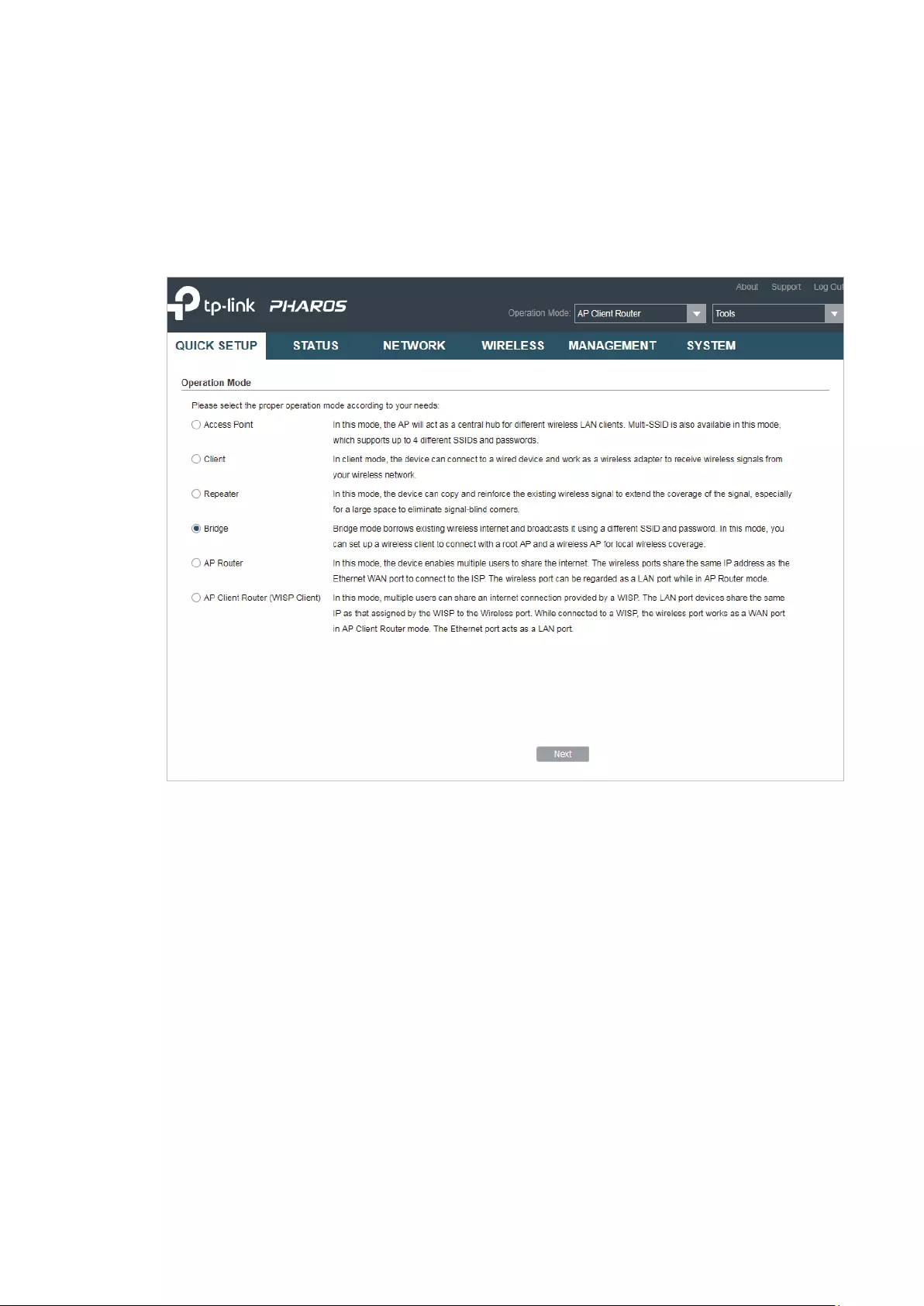
1.4 Bridge
The device in Bridge mode can extend wireless coverage of an existing wireless network.
The SSID and encryption type of the device can be different from those of root AP.
Access Point Client
LAN: 192.168.0.254
Switch
Oce Oce
SSID: abc
Bridge
LAN: 192.168.0.2 LAN: 192.168.0.3
SSID: 123
Switch
Network requirements: Extend the wireless network to eliminate the wireless signal-blind
areas. Users can use different SSID and encryption type from those of the root AP device
to access the network.
The device in the network: Similar to the Repeater mode, the Bridge mode is used to
enhance the exiting wireless signal. However, the difference is that the extended wireless
network has its own SSID and encryption type different from those of root AP.
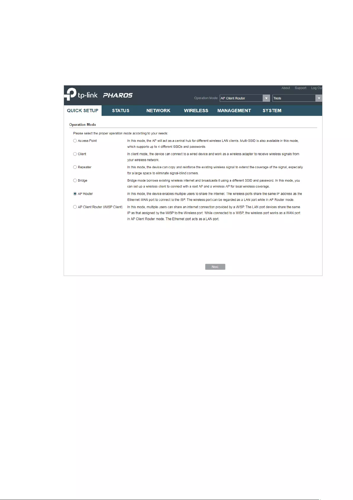
1.5 AP Router
The device in AP Router mode serves as a normal home wireless router but provides a
wider wireless network range.
Internet
Modem
Network requirements: Establish the wireless network coverage in the campus,
community, industrial park or other public places and so on.
The device in the network: The device in AP Router mode connects to root ADSL/Cable
AP Router
Laptop/Tablet/Smartphone
7
Modem for internet access. Meanwhile, it creates a wireless network for the wireless
clients to connect to the internet.
Note:
In this mode, the device cannot be managed directly through the port connected to ADSL/Cable
Modem. To manage the device, you can connect the management host to the device wirelessly or
via the other LAN port.
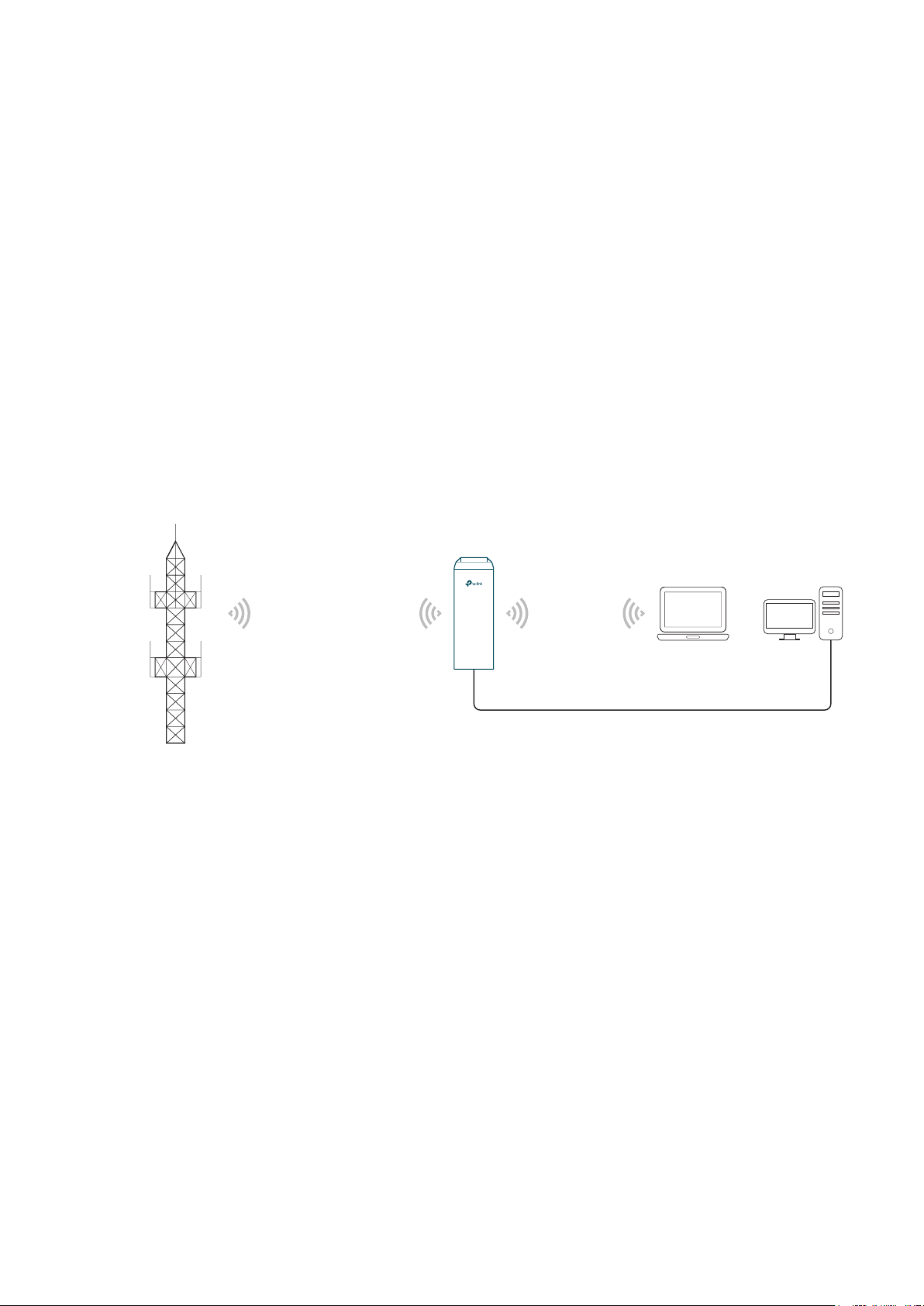
1.6 AP Client Router (WISP Client)
In AP Client Router mode, the device access the internet provided by WISP (Wireless
Internet Service Provider) through wireless connection. For the downstream clients, the
device serves as a normal home wireless router. It can provide wired connection and
wireless connection simultaneously.
AP Client Router
WISP
LAN: 192.168.0.254
WAN: Dynamic IP
WISP’s network
User Network
Network requirements: Get internet service from WISP.
The device in the network: The device in Client Router Mode connects to WISP wirelessly
for internet service. It provides both wired access and wireless access for the clients.
8

2
This chapter introduces how to quickly build a wireless network in different operation
modes. Follow the steps below:
2.1 Check the System Requirements
2.2 Log In to the Device
2.3 Set Up the Wireless Network
Quick Start
9
2.1 Check the System Requirements
Operating System:
Microsoft Windows XP, Windows Vista, Windows 7, Windows 8, Windows 10, Linux, or
Mac OS X.
Web Browser
Google Chrome, Safari, Firefox, and Apple Safari. IE browsers are not recommended.
2.2 Log In to the Device
Before configuring the device, you need to access the PharOS configuration interface.
Follow the steps below:
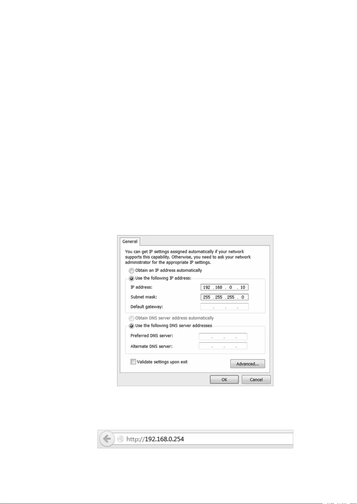
1. Connect your PC to the device.
2. Set the IP address of your PC as static IP address on 192.168.0.X subnet (X ranges from
2 to 253, e.g.192.168.0.10).
3. Launch a web browser on and enter the management IP address of the device
(192.168.0.254 by default) in the address bar to load the login page of the PharOS
configuration interface.
10
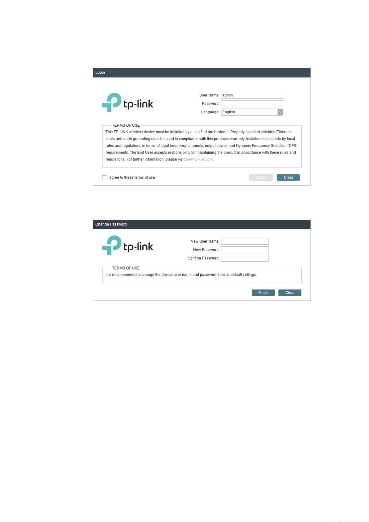
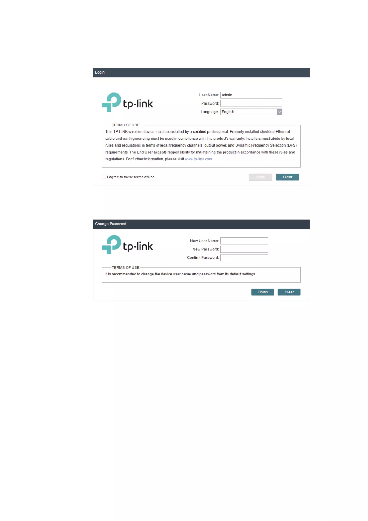
4. Use admin for both of
User Name
and
Password
. Select the appropriate language from
the Language drop-down list. Read and agree the terms of use, then click
5. Create a new username and password for network security. Click
PharOS.
Login
Finish
to log in to the
.
2.3 Set Up the Wireless Network
You can use the Quick Setup wizard to quickly configure your device step by step. Choose
the suitable operation mode according to your network environment and follow the step-
by-step instructions.
11

Access Point
Follow the steps below to configure the device as Access Point mode:
1. Go to the QUICK SETUP page, select
Access Point
and click
Next
.
12
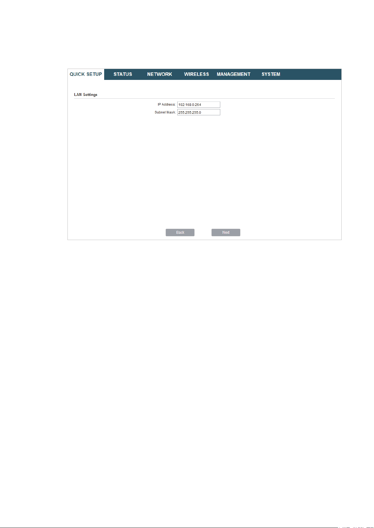
2. In the LAN Settings section, specify the LAN IP address and the Subnet Mask for the
device. Then, click
Next
.
13
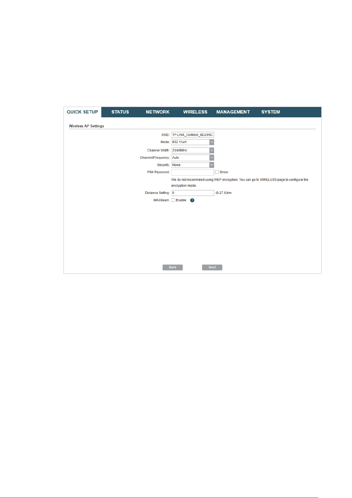
3. In the Wireless AP Settings section, specify the basic wireless parameters to create a
wireless network. Click
Next
.
Tips:
It is recommended to specify
·
You can keep the default settings or specify the parameters according to your need. For details,
·
refer to
5. Configure the Wireless Parameters
Security
as WPA-PSK/WPA2-PSK for the network security.
.
14
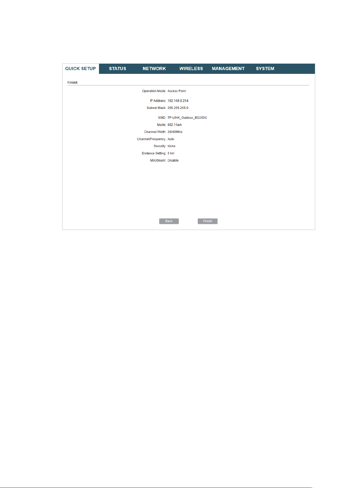
4. In the Finish section, review the configurations and click
setup.
Finish
to complete the quick
5. Connect the device according to your network topology and use it normally.
15
Client
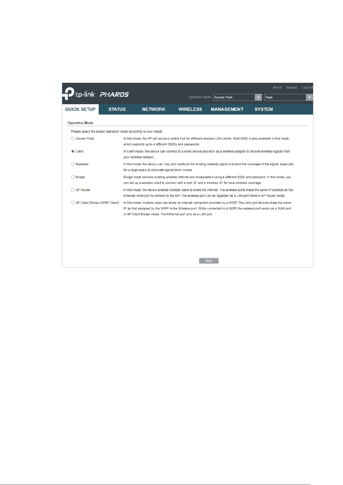
Follow the steps below to configure the device as Client mode:
1. Go to the QUICK SETUP page, select
Client
and click
Next
.
16

2. In the LAN Settings section, specify the LAN IP Address and the Subnet Mask for the
device. Then, click
Next
.
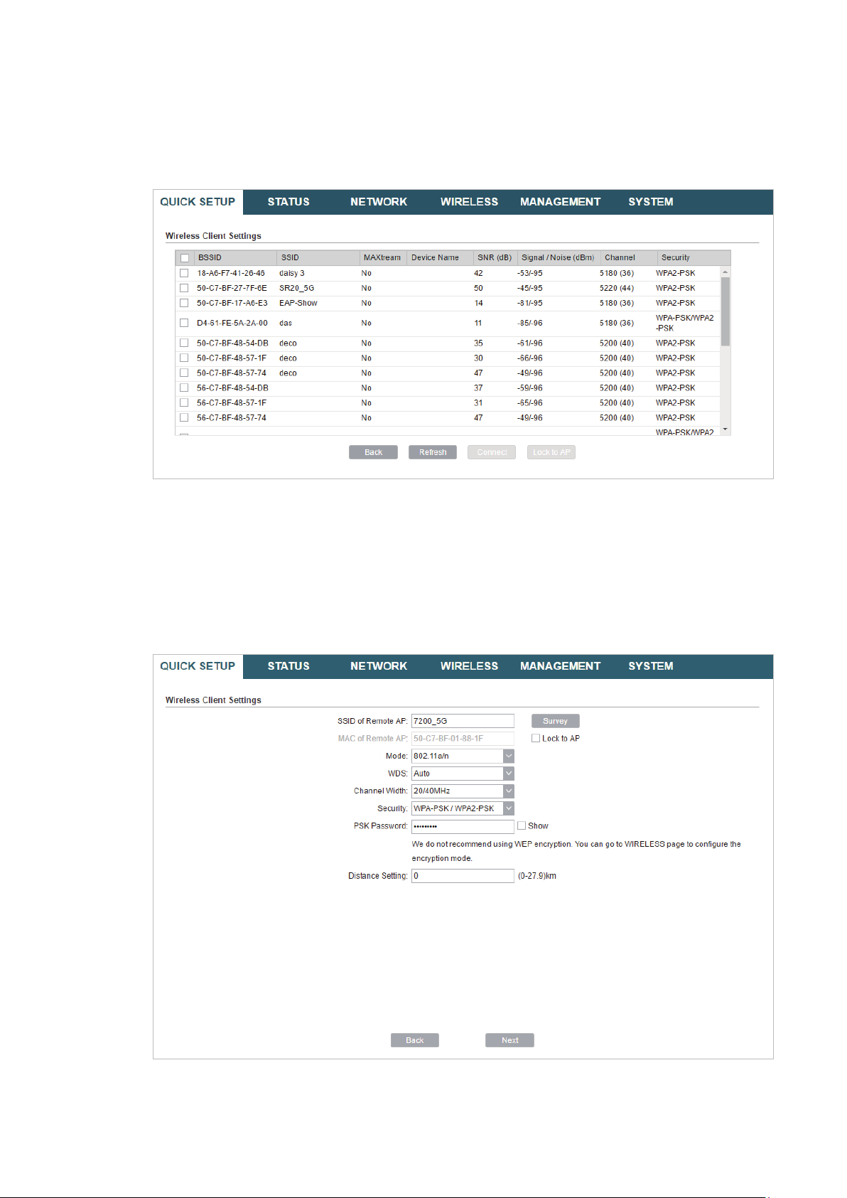
3. In the Wireless Client Settings section, click
network.
Survey
to search for the upstream wireless
4. Select the desired wireless network and click
17
Connect
.
Tips:
There may be two or more networks with the same SSID in the AP list. Click
the SSID and AP simultaneously, which can make the device connect to the specific AP next
time.
Lock to AP
to select
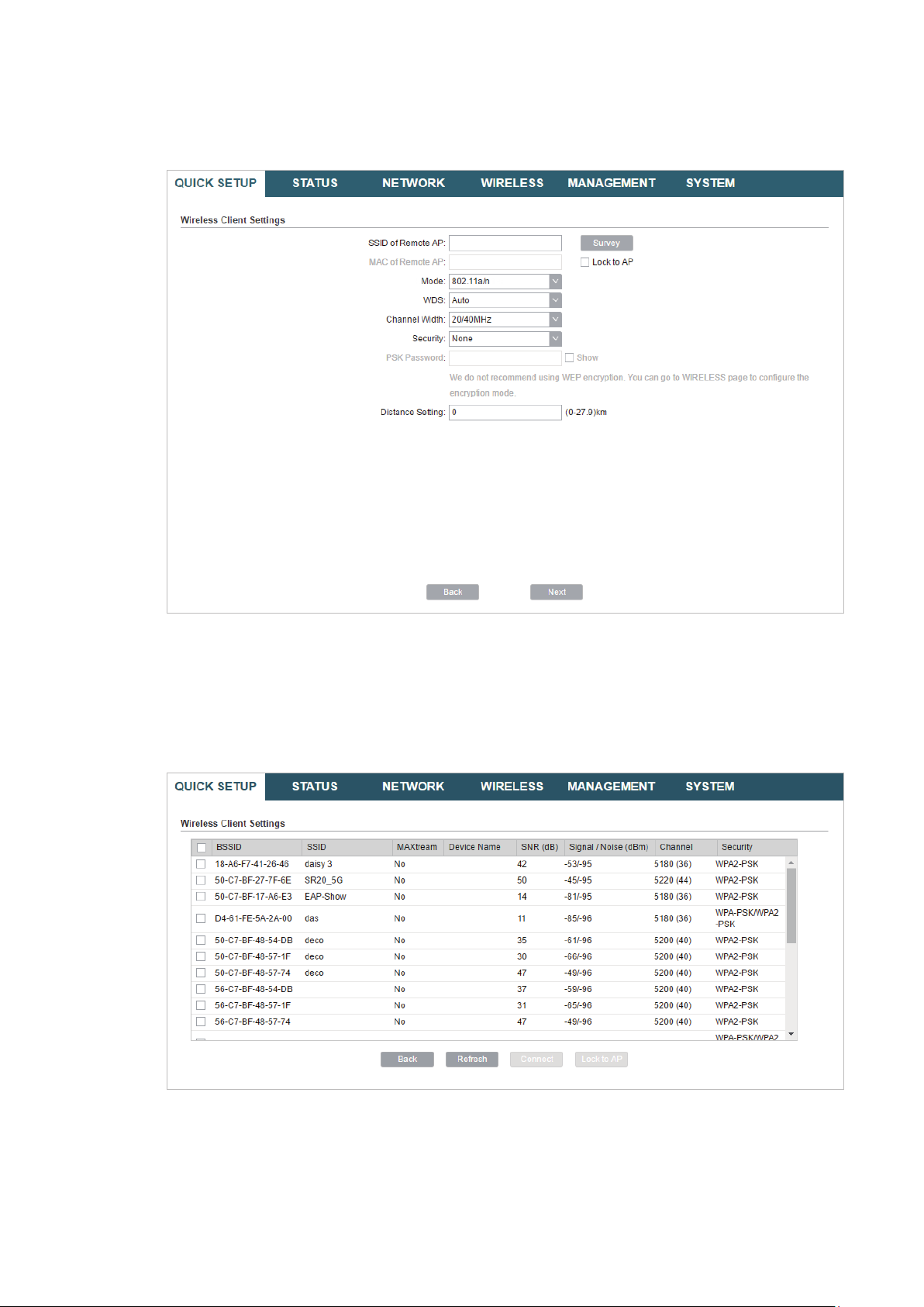
5. In the Wireless Client Settings section, specify the wireless parameters to connect to
the specified wireless network. Click
Next
.
Note:
Make sure that
Other parameters set in this page and those of the upstream wireless network should be
compatible with each other. For details, refer to
Security
and
PSK Password
are the same as the upstream wireless network’s.
5. Configure the Wireless Parameters
.
18

6. In the Finish section, review the configurations and click
setup.
Finish
to complete the quick
7. Connect the device according to your network topology and use it normally.
Repeater (Range Extender)
Follow the steps below to configure the device as Repeater (Range Extender) mode:
19

1. Go to the QUICK SETUP page, select
Repeater
and click
Next
.
2. In the LAN Settings section, specify the LAN IP address and the Subnet Mask for the
device. Then, click
Next
.
20
3. In the Wireless Client Settings section, click
network.
Survey
to search for the upstream wireless
4. Select the desired wireless network and click
Connect
.
Tips:
There may be two or more networks with the same SSID in the AP list. Click
the SSID and AP simultaneously, which can make the device connect to the specific AP next
time.
Lock to AP
to select
5. In the Wireless Client Settings section, specify the wireless parameters to connect to
the specified wireless network. Click
Next
21
.
Note:
Make sure that
Other parameters set in this page and those of the upstream wireless network should be
compatible with each other. For details, refer to
Security
and
PSK Password
are the same as the upstream wireless network’s.
5. Configure the Wireless Parameters
.
6. In the Finish section, review the configurations and click
setup.
Finish
to complete the quick
22
7. Connect the device according to your network topology and use it normally.
Bridge
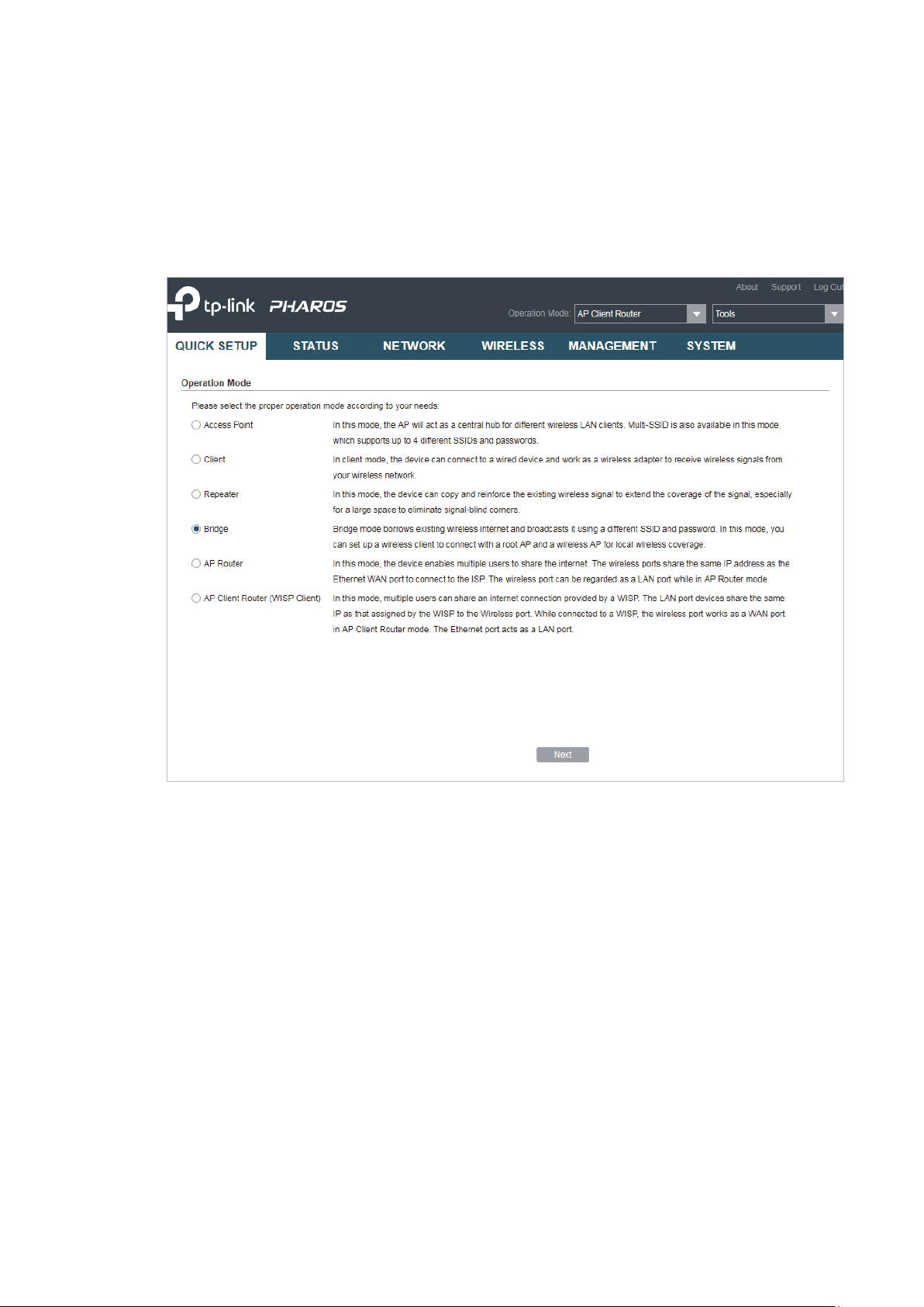
Follow the steps below to configure the device as Bridge mode:
1. Go to the QUICK SETUP page, select
Bridge
and click
Next
.
23
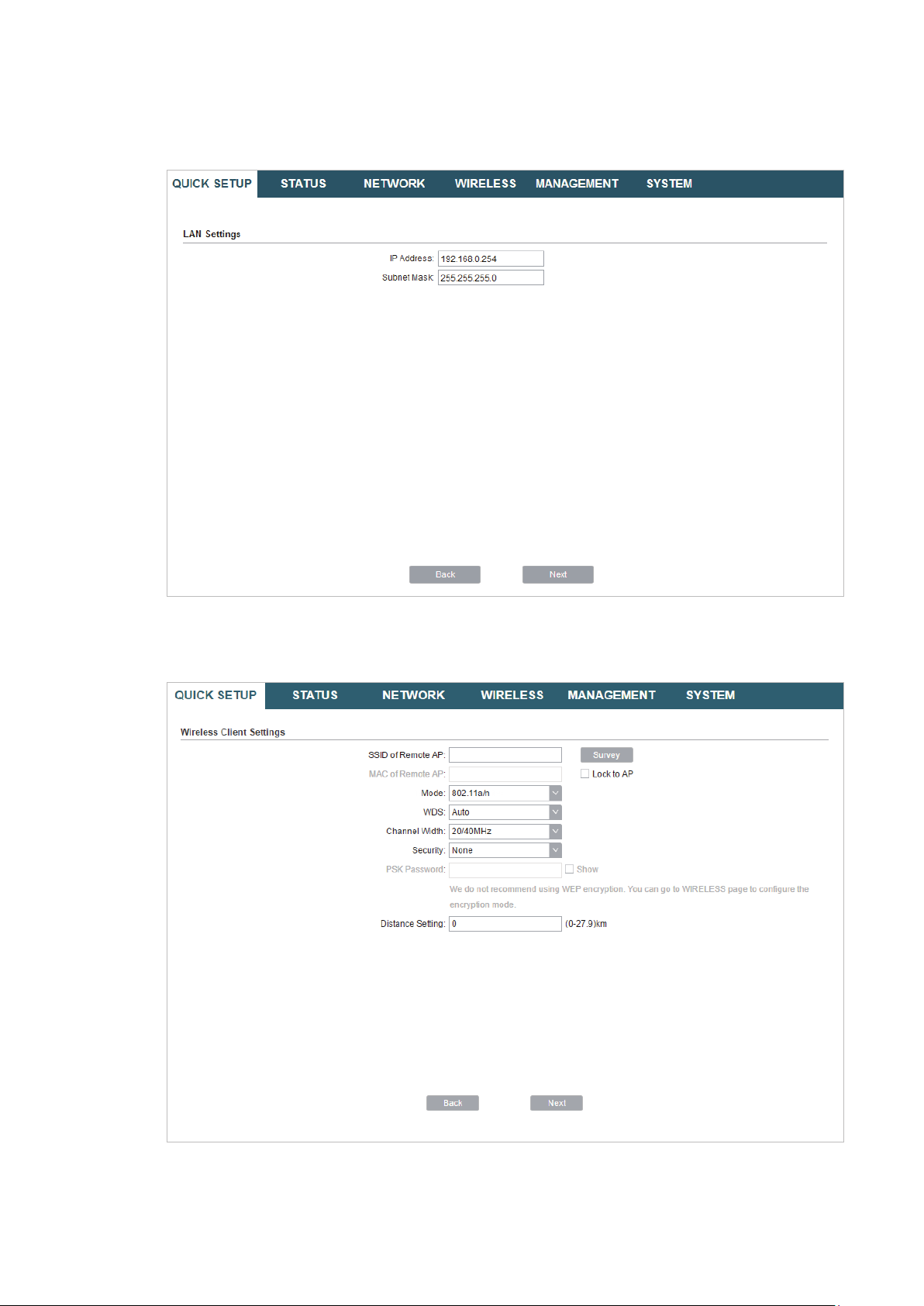
2. In the LAN Settings section, specify the LAN IP address and the Subnet Mask for the
device. Then, click
Next
.
3. In the Wireless Client Settings section, click
network.
Survey
to search for the upstream wireless
4. Select the desired wireless network and click
24
Connect
.

Tips:
There may be two or more networks with the same SSID in the AP list. Click
the SSID and AP simultaneously, which can make the device connect to the specific AP next
time.
Lock to AP
to select
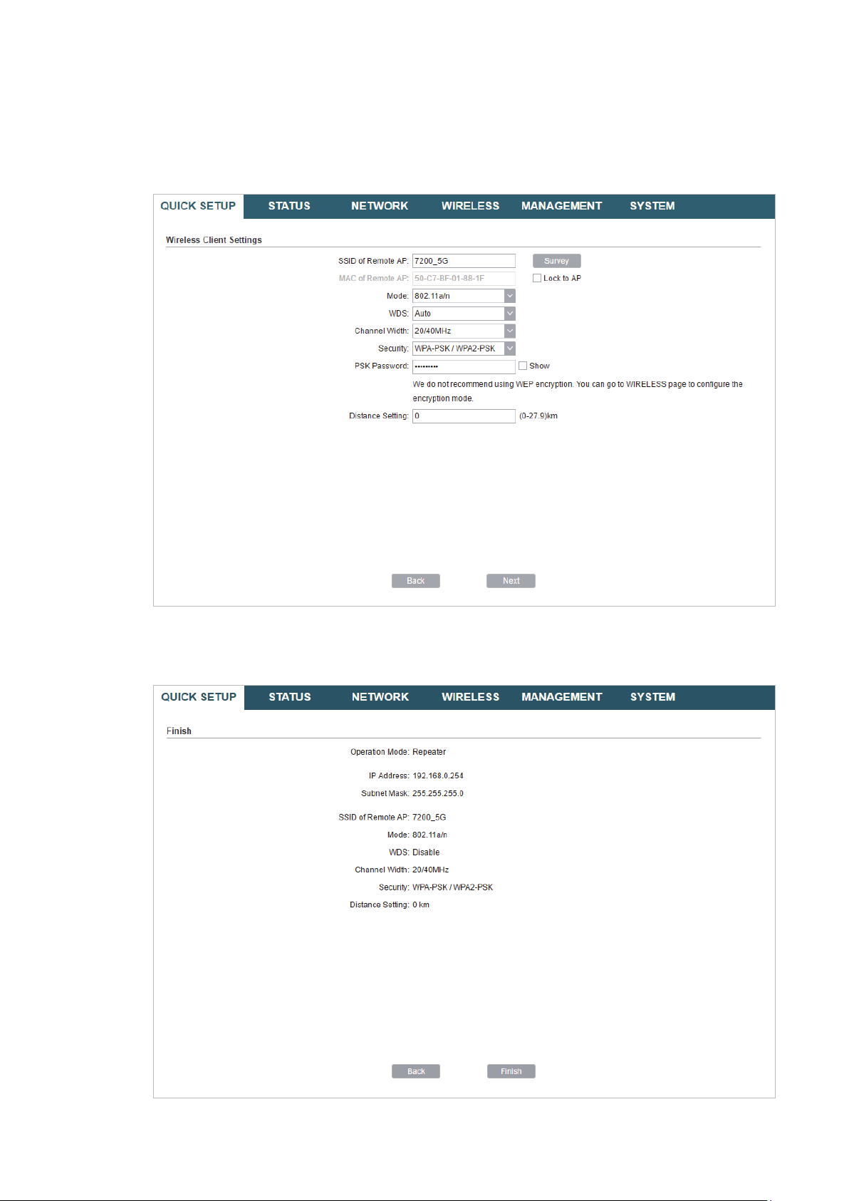
5. In the Wireless Client Settings section, specify the wireless parameters to connect to
the specified wireless network. Click
Next
.
Note:
Make sure that the
Other parameters set in this page and those of the upstream wireless network should be
compatible with each other. For details, refer to
Security
and
PSK Password
are the same as the upstream wireless network’s.
5. Configure the Wireless Parameters
.
25
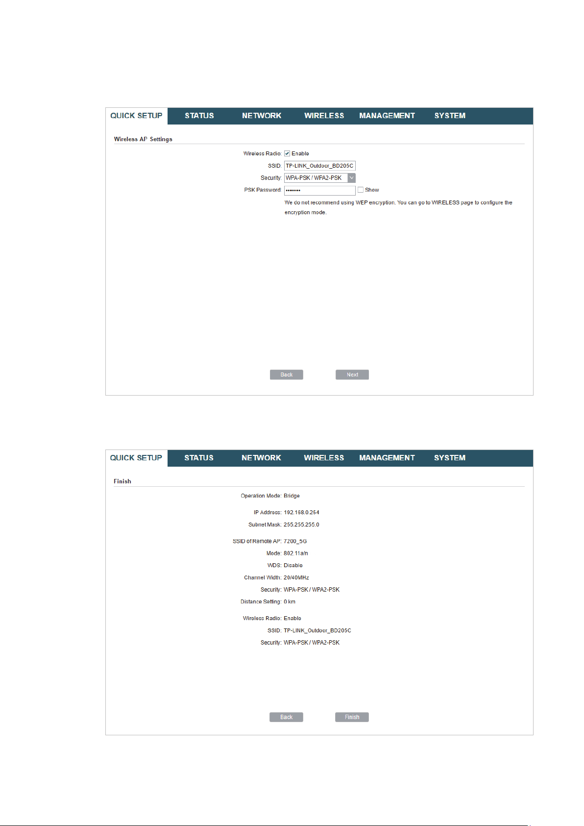
6. In the Wireless AP Settings section, specify the parameters to create a new wireless
network for the downstream clients. Click
Next
.
7. In the Finish section, review the configurations and click
setup.
Finish
to complete the quick
8. Connect the device according to your network topology and use it normally.
26
Loading…

User Guide
For TP-Link Pharos Series Products
CPE210 / CPE220 / CPE510 / CPE520 / CPE610
WBS210 / WBS510
1910012510 REV 3.0.2
December 2018

CONTENTS
About this User Guide …………………………………………………………………………………………… 1
Overview ………………………………………………………………………………………………………………… 2
1 Operation Modes …………………………………………………………………………………………….. 3
1.1 Access Point ……………………………………………………………………………………………………………………………… 4
1.2 Client …………………………………………………………………………………………………………………………………………… 5
1.3 Repeater (Range Extender) …………………………………………………………………………………………………….. 6
1.4 Bridge …………………………………………………………………………………………………………………………………………. 7
1.5 AP Router …………………………………………………………………………………………………………………………………… 7
1.6 AP Client Router (WISP Client) ……………………………………………………………………………………………….. 8
2 Quick Start ……………………………………………………………………………………………………….. 9
2.1 Check the System Requirements …………………………………………………………………………………………10
2.2 Log In to the Device ………………………………………………………………………………………………………………..10
2.3 Set Up the Wireless Network …………………………………………………………………………………………………11
Access Point ……………………………………………………………………………………………………………………………….. 12
Client …………………………………………………………………………………………………………………………………………… 16
Repeater (Range Extender) ………………………………………………………………………………………………………. 19
Bridge …………………………………………………………………………………………………………………………………………… 23
AP Router …………………………………………………………………………………………………………………………………….. 27
AP Client Router (WISP Client) …………………………………………………………………………………………………. 32
3 Monitor the Network ……………………………………………………………………………………..38
3.1 View the Device Information ………………………………………………………………………………………………….39
3.2 View the Wireless Settings …………………………………………………………………………………………………….39
3.3 View Wireless Signal Quality………………………………………………………………………………………………….40
3.4 View Radio Status ……………………………………………………………………………………………………………………41
3.5 View the LAN Settings …………………………………………………………………………………………………………….43
3.6 View the WAN Settings …………………………………………………………………………………………………………..43

3.7 Monitor Throughput ………………………………………………………………………………………………………………..44
3.8 Monitor Stations ………………………………………………………………………………………………………………………44
3.9 Monitor Interfaces …………………………………………………………………………………………………………………..45
3.10 Monitor ARP Table …………………………………………………………………………………………………………………..46
3.11 Monitor Routes ………………………………………………………………………………………………………………………..46
3.12 Monitor DHCP Clients ……………………………………………………………………………………………………………..47
3.13 Monitor Dynamic WAN ……………………………………………………………………………………………………………47
4 Configure the Network ………………………………………………………………………………….49
4.1 Configure WAN Parameters …………………………………………………………………………………………………..50
4.2 Configure LAN Parameters ……………………………………………………………………………………………………57
Access Point/Client/Repeater/Bridge Mode …………………………………………………………………………. 57
AP Router/AP Client Router Mode …………………………………………………………………………………………… 60
4.3 Configure Management VLAN ………………………………………………………………………………………………62
4.4 Configure the Forwarding Feature ……………………………………………………………………………………….62
4.5 Configure the Security Feature …………………………………………………………………………………………….66
4.6 Configure Access Control ……………………………………………………………………………………………………..69
4.7 Configure Static Routing ………………………………………………………………………………………………………..70
4.8 Configure Bandwidth Control ………………………………………………………………………………………………..71
4.9 Configure IP & MAC Binding …………………………………………………………………………………………………..73
5 Configure the Wireless Parameters …………………………………………………………… 75
5.1 Configure Basic Wireless Parameters …………………………………………………………………………………76
5.2 Configure Wireless Client Parameters ………………………………………………………………………………..78
5.3 Configure Wireless AP Parameters ………………………………………………………………………………………82
5.4 Configure Multi-SSID ………………………………………………………………………………………………………………88
5.5 Configure Wireless MAC Filtering ………………………………………………………………………………………..90
5.6 Configure Advanced Wireless Parameters …………………………………………………………………………91
6 Manage the Device ……………………………………………………………………………………….. 94
6.1 Manage System Logs ……………………………………………………………………………………………………………..95

6.2 Specify the Miscellaneous Parameters ……………………………………………………………………………….96
6.3 Configure Ping Watch Dog …………………………………………………………………………………………………….97
6.4 Configure Dynamic DNS …………………………………………………………………………………………………………98
6.5 Configure Web Server…………………………………………………………………………………………………………….99
6.6 Configure SNMP Agent ……………………………………………………………………………………………………….. 100
6.7 Configure SSH Server …………………………………………………………………………………………………………. 102
6.8 Configure RSSI LED Thresholds ………………………………………………………………………………………… 102
7 Configure the System ………………………………………………………………………………… 104
7.1 Configure Device Information ……………………………………………………………………………………………. 105
7.2 Configure Location Information ………………………………………………………………………………………… 105
7.3 Configure User Account ……………………………………………………………………………………………………… 105
7.4 Configure Time Settings …………………………………………………………………………………………………….. 106
7.5 Update Firmware ………………………………………………………………………………………………………………….. 108
7.6 Configure Other Settings ……………………………………………………………………………………………………. 109
8 Use the System Tools ………………………………………………………………………………… 110
8.1 Configure Ping ……………………………………………………………………………………………………………………… 111
8.2 Configure Traceroute ………………………………………………………………………………………………………….. 111
8.3 Test Speed ……………………………………………………………………………………………………………………………. 112
8.4 Survey ……………………………………………………………………………………………………………………………………. 113
8.5 Analyze Spectrum ………………………………………………………………………………………………………………… 115

1
About this User Guide
This User Guide contains information for setup and management of TP-Link Pharos series
products. Please read this guide carefully before operation.
When using this guide, please notice that features of the product may vary slightly depending on
the model and software version you have, and on your location, language, and internet service
provider. All screenshots, images, parameters and descriptions documented in this guide are used
for demonstration only.
Some models featured in this guide may be unavailable in your country or region. For local sales
information, visit
http://www.tp-link.com
.
The information in this document is subject to change without notice. Every effort has been made
in the preparation of this document to ensure the accuracy of the contents, but all statements,
information, and recommendations in this document do not constitute the warranty of any kind,
express or implied. Users must take full responsibility for their application of any products.
Convention
Unless otherwise noted, the introduction in this guide takes CPE510 as an example.
More Info
The latest software, management app and utility can be found at Download Center at
https://www.tp-link.com/support
.
The Quick Installation Guide can be found where you find this guide or inside the package of the
product.
Specifications can be found on the product page at
https://www.tp-link.com
.
Our Technical Support contact information can be found at the Contact Technical Support page at
https://www.tp-link.com/support
.
To ask questions, find answers, and communicate with TP-Link users or engineers, please visit
https://community.tp-link.com
to join TP-Link Community.

2
Overview
is TP-Link’s next generation outdoor product series dedicated to long-distance
outdoor wireless networking solutions.
is a powerful Web-based operating system, which is integrated into all Pharos series
products.
New features of Pharos series products are listed as follows:
• Provides User-friendly UI design.
• TP-Link Pharos MAXtream (Time-Division-Multiple-Access) technology improves product
performance in throughput, capacity and latency, which are ideal for point-to-multipoint
applications.
• Supports multiple operation modes: Access Point, Client, Repeater (Range Extender), Bridge, AP
Router and AP Client Router (WISP Client).
• Provides system-level optimization for long-distance wireless transmission.
• Supports selectable bandwidth of 5/10/20/40MHz.
• Supports easy antenna alignment with Wireless Signal Indicators on Web interface.
• Provides Throughput Monitor, Spectrum Analyzer, Speed Test and Ping tools.
• Supports discovery and management via Pharos Control application.

3
1 Operation Modes
The Pharos series products support six operation modes to satisfy user’s diversified
network requirements. This chapter introduces typical usage scenarios of different
modes, including:
1.1 Access Point
1.2 Client
1.3 Repeater (Range Extender)
1.4 Bridge
1.5 AP Router
1.6 AP Client Router (WISP Client)
4
1.1 Access Point
In AP mode, the device acts as a central hub and provides wireless access point for
wireless clients, thus the AP mode is applicable to the following three scenarios.
Meanwhile, Multi-SSID function can be enabled in this mode, providing up to four wireless
networks with different SSIDs and passwords.
Scenario 1
Access Point
LAN: 192.168.7.2
AP Client Router
LAN: 192.168.0.254
WAN: Dynamic IP
LAN: 192.168.7.1
Router
Internet
Network requirements: Establish the network coverage in the remote areas without long-
distance cabling.
The device in the network: In the adjacent town covered by wired network, ISP (Internet
Service Provider) can put up a device in AP mode to access the internet and transform
wired signal into wireless one. In the remote area, users can put up a device in AP Client
Router mode to access the wireless network.
Advantages: Transmit data wirelessly across a long distance and reduce the cabling cost.
Scenario 2
Access Point Client
Switch
LAN: 192.168.0.254 LAN: 192.168.0.2
Switch
Oce Oce
5
Network requirements: Combine two separate office networks into one.
The device in the network: The device in AP mode connects to one office network
and creates a wireless network. The device in Client mode connects to the other office
network and the wireless network.
Advantages: Establish a point-to-point WLAN across a long distance to achieve the
connectivity between two networks and avoid the cabling trouble.
Scenario 3
Access Point
Internet
Laptop/Tablet/Smartphone
Wired Local
Area Network
Network requirements: Establish wireless network coverage in the campus, community,
industrial park or public place to provide wireless access for users.
The device in the network: With the access to campus wired network or other wired local
area networks, the device in AP mode provides the wireless access for wireless clients,
such as smart phones, laptops and tablets to connect to the network.
Advantages: Enrich the access ways of local area network and extend the network
coverage.
1.2 Client
For the device in Client mode, the most common usage scenario is point-to-point
networking. The device is used to transform wireless signal into wired one.
Access Point Client
Switch
LAN: 192.168.0.254 LAN: 192.168.0.2
Switch
Oce Oce

6
Network requirements: Help the wired devices to connect to the wireless network.
The device in the network: In Client mode, the device actually serves as a wireless adapter
to receive the wireless signal from root AP or Station. In this case, wired devices can
access the wireless network by connecting to the device in Client mode.
1.3 Repeater (Range Extender)
The device in Repeater mode can extend wireless coverage of an existing wireless
network. The SSID and encryption type of the device should be the same as those of the
root AP.
SSID: abc
SSID: abc
Access Point Client
Switch
LAN: 192.168.0.254
Repeater
LAN: 192.168.0.2 LAN: 192.168.0.3
Switch
Oce Oce
Network requirements: Repeat wireless signal and extend the wireless network coverage.
The device in the network: If you want to combine two networks via wireless connection
but the distance is beyond the networks’ wireless coverage range, you can put one or
more devices in Repeater mode along the path to repeat the wireless signal and extend
the wireless transmission range.

7
1.4 Bridge
The device in Bridge mode can extend wireless coverage of an existing wireless network.
The SSID and encryption type of the device can be different from those of root AP.
SSID: abc
SSID: 123
Access Point Client
Switch
LAN: 192.168.0.254
Bridge
LAN: 192.168.0.2 LAN: 192.168.0.3
Switch
Oce Oce
Network requirements: Extend the wireless network to eliminate the wireless signal-blind
areas. Users can use different SSID and encryption type from those of the root AP device
to access the network.
The device in the network: Similar to the Repeater mode, the Bridge mode is used to
enhance the exiting wireless signal. However, the difference is that the extended wireless
network has its own SSID and encryption type different from those of root AP.
1.5 AP Router
The device in AP Router mode serves as a normal home wireless router but provides a
wider wireless network range.
Modem
AP Router
Laptop/Tablet/Smartphone
Internet
Network requirements: Establish the wireless network coverage in the campus,
community, industrial park or other public places and so on.
The device in the network: The device in AP Router mode connects to root ADSL/Cable

8
Modem for internet access. Meanwhile, it creates a wireless network for the wireless
clients to connect to the internet.
Note:
In this mode, the device cannot be managed directly through the port connected to ADSL/Cable
Modem. To manage the device, you can connect the management host to the device wirelessly or
via the other LAN port.
1.6 AP Client Router (WISP Client)
In AP Client Router mode, the device access the internet provided by WISP (Wireless
Internet Service Provider) through wireless connection. For the downstream clients, the
device serves as a normal home wireless router. It can provide wired connection and
wireless connection simultaneously.
AP Client Router
LAN: 192.168.0.254
WAN: Dynamic IP
WISP
WISP’s network User Network
Network requirements: Get internet service from WISP.
The device in the network: The device in Client Router Mode connects to WISP wirelessly
for internet service. It provides both wired access and wireless access for the clients.

9
2 Quick Start
This chapter introduces how to quickly build a wireless network in different operation
modes. Follow the steps below:
2.1 Check the System Requirements
2.2 Log In to the Device
2.3 Set Up the Wireless Network
10
2.1 Check the System Requirements
Operating System:
Microsoft Windows XP, Windows Vista, Windows 7, Windows 8, Windows 10, Linux, or
Mac OS X.
Web Browser
Google Chrome, Safari, Firefox, and Apple Safari. IE browsers are not recommended.
2.2 Log In to the Device
Before configuring the device, you need to access the PharOS configuration interface.
Follow the steps below:
1. Connect your PC to the device.
2. Set the IP address of your PC as static IP address on 192.168.0.X subnet (X ranges from
2 to 253, e.g.192.168.0.10).
3. Launch a web browser on and enter the management IP address of the device
(192.168.0.254 by default) in the address bar to load the login page of the PharOS
configuration interface.
11
4. Use admin for both of
User Name
and
Password
. Select the appropriate language from
the Language drop-down list. Read and agree the terms of use, then click
Login
.
5. Create a new username and password for network security. Click
Finish
to log in to the
PharOS.
2.3 Set Up the Wireless Network
You can use the Quick Setup wizard to quickly configure your device step by step. Choose
the suitable operation mode according to your network environment and follow the step-
by-step instructions.
12
Access Point
Follow the steps below to configure the device as Access Point mode:
1. Go to the QUICK SETUP page, select
Access Point
and click
Next
.

13
2. In the LAN Settings section, specify the LAN IP address and the Subnet Mask for the
device. Then, click
Next
.

14
3. In the Wireless AP Settings section, specify the basic wireless parameters to create a
wireless network. Click
Next
.
Tips:
· It is recommended to specify
Security
as WPA-PSK/WPA2-PSK for the network security.
· You can keep the default settings or specify the parameters according to your need. For details,
refer to
5. Configure the Wireless Parameters
.

15
4. In the Finish section, review the configurations and click
Finish
to complete the quick
setup.
5. Connect the device according to your network topology and use it normally.

16
Client
Follow the steps below to configure the device as Client mode:
1. Go to the QUICK SETUP page, select
Client
and click
Next
.

17
2. In the LAN Settings section, specify the LAN IP Address and the Subnet Mask for the
device. Then, click
Next
.
3. In the Wireless Client Settings section, click
Survey
to search for the upstream wireless
network.
4. Select the desired wireless network and click
Connect
.

18
Tips:
There may be two or more networks with the same SSID in the AP list. Click
Lock to AP
to select
the SSID and AP simultaneously, which can make the device connect to the specific AP next
time.
5. In the Wireless Client Settings section, specify the wireless parameters to connect to
the specified wireless network. Click
Next
.
Note:
Make sure that
Security
and
PSK Password
are the same as the upstream wireless network’s.
Other parameters set in this page and those of the upstream wireless network should be
compatible with each other. For details, refer to
5. Configure the Wireless Parameters
.

19
6. In the Finish section, review the configurations and click
Finish
to complete the quick
setup.
7. Connect the device according to your network topology and use it normally.
Repeater (Range Extender)
Follow the steps below to configure the device as Repeater (Range Extender) mode:

20
1. Go to the QUICK SETUP page, select
Repeater
and click
Next
.
2. In the LAN Settings section, specify the LAN IP address and the Subnet Mask for the
device. Then, click
Next
.

21
3. In the Wireless Client Settings section, click
Survey
to search for the upstream wireless
network.
4. Select the desired wireless network and click
Connect
.
Tips:
There may be two or more networks with the same SSID in the AP list. Click
Lock to AP
to select
the SSID and AP simultaneously, which can make the device connect to the specific AP next
time.
5. In the Wireless Client Settings section, specify the wireless parameters to connect to
the specified wireless network. Click
Next
.

22
Note:
Make sure that
Security
and
PSK Password
are the same as the upstream wireless network’s.
Other parameters set in this page and those of the upstream wireless network should be
compatible with each other. For details, refer to
5. Configure the Wireless Parameters
.
6. In the Finish section, review the configurations and click
Finish
to complete the quick
setup.
23
7. Connect the device according to your network topology and use it normally.
Bridge
Follow the steps below to configure the device as Bridge mode:
1. Go to the QUICK SETUP page, select
Bridge
and click
Next
.

24
2. In the LAN Settings section, specify the LAN IP address and the Subnet Mask for the
device. Then, click
Next
.
3. In the Wireless Client Settings section, click
Survey
to search for the upstream wireless
network.
4. Select the desired wireless network and click
Connect
.

25
Tips:
There may be two or more networks with the same SSID in the AP list. Click
Lock to AP
to select
the SSID and AP simultaneously, which can make the device connect to the specific AP next
time.
5. In the Wireless Client Settings section, specify the wireless parameters to connect to
the specified wireless network. Click
Next
.
Note:
Make sure that the
Security
and
PSK Password
are the same as the upstream wireless network’s.
Other parameters set in this page and those of the upstream wireless network should be
compatible with each other. For details, refer to
5. Configure the Wireless Parameters
.

26
6. In the Wireless AP Settings section, specify the parameters to create a new wireless
network for the downstream clients. Click
Next
.
7. In the Finish section, review the configurations and click
Finish
to complete the quick
setup.
8. Connect the device according to your network topology and use it normally.
27
AP Router
Follow the steps below to configure the device as AP Router mode:
1. Go to the QUICK SETUP page, select
AP Router
and click
Next
.

28
2. In the WAN Connection Type section, specify the connection type according to your
need and click
Next
.
The device supports three types of the WAN connection, including
PPPoE
,
Dynamic IP
and
Static IP
. You can contact with your ISP to confirm your WAN connection type.
29
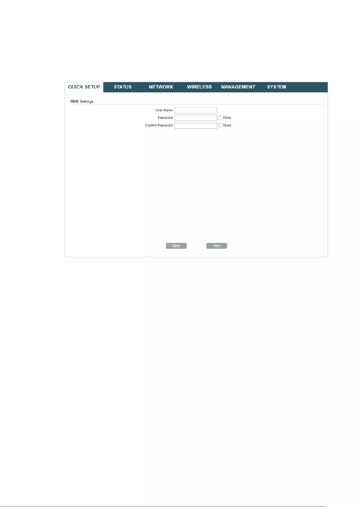
PPPoE
Select
PPPoE
and click
Next
, then the following page will appear. In the WAN Settings
section, specify the parameters that are provided by your ISP and click
Next
.
Dynamic IP
Select
Dynamic IP
and click
Next
. In this type, the device will obtain a WAN connection
automatically without any WAN configurations.
30
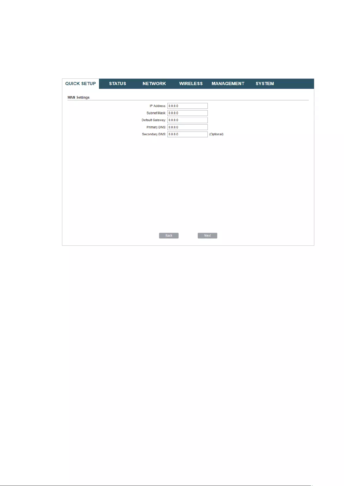
Static IP
Select
Static IP
and click
Next
, then the following page will appear. In the WAN Settings
section, specify the parameters that are provided by your ISP and click
Next
.
3. In the Wireless AP Settings section, specify the basic wireless parameters to create a
wireless network. Click
Next
.

31
Tips:
· It is recommended to specify
Security
as WPA-PSK/WPA2-PSK for the network security.
· You can keep the default settings or specify the parameters according to your need. For details,
refer to
5. Configure the Wireless Parameters
.
4. In the Finish section, review the configurations and click
Finish
to complete the quick
setup.
32
5. Connect the device according to your network topology and use it normally.
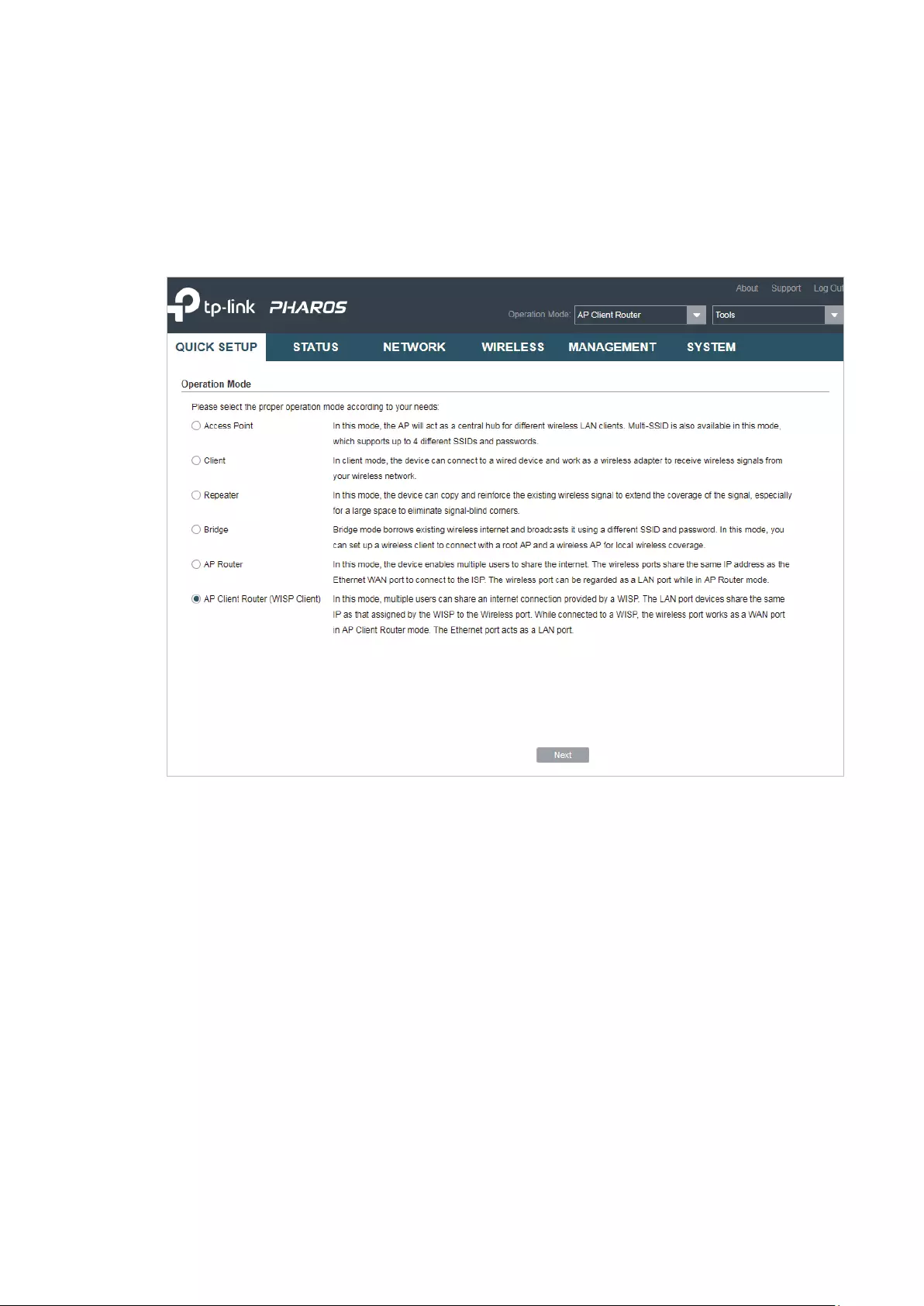
AP Client Router (WISP Client)
Follow the steps below to configure the device as AP Client Router (WISP Client) mode:
1. Go to the QUICK SETUP page, select
AP Client Router (WISP Client)
and click
Next
.

33
2. In the WAN Connection Type section, choose the connection type according to your
need and click
Next
.
The device supports types,
PPPoE
,
Dynamic IP
and
Static IP
for the WAN connection.
You can contact with your ISP to confirm your WAN connection type.

34
PPPoE
Select
PPPoE
and click
Next
, then the following page will appear. In the WAN Settings
section, specify the parameters that are provided by your ISP and click
Next
.
Dynamic IP
Select
Dynamic IP
and click
Next
. In this type, the device will obtain a WAN connection
automatically without any WAN configurations.
35
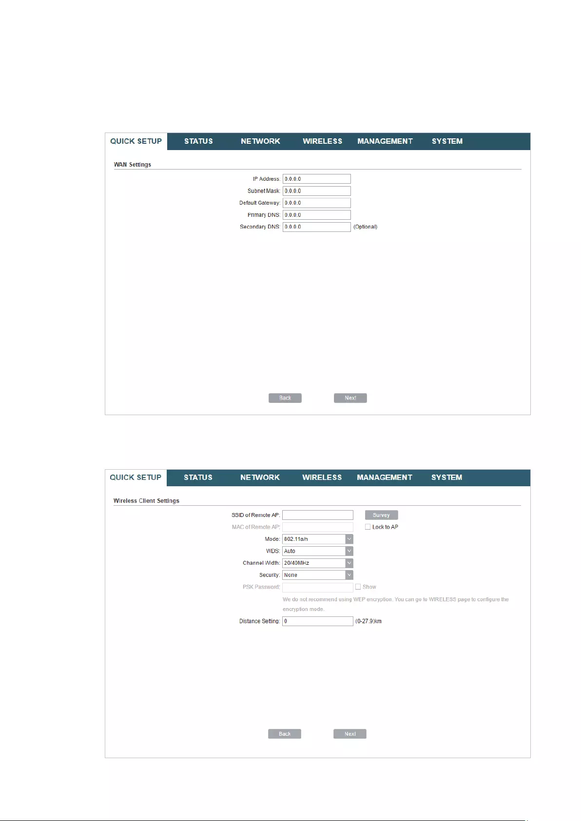
Static IP
Select
Static IP
and click
Next
, then the following page will appear. In the WAN Settings
section, specify the parameters that are provided by your ISP and click
Next
.
3. In the Wireless Client Settings section, click
Survey
to search for the upstream wireless
network.

36
4. Select the desired wireless network and click
Connect
.
Tips:
There may be two or more networks with the same SSID in the AP list. Click
Lock to AP
to select
the SSID and AP simultaneously, which can make the device connect to the specific AP next
time.
5. In the Wireless Client Settings section, specify the wireless parameters to connect to
the specified wireless network. Click
Next
.
Note:
Make sure that
Security
and
PSK Password
are the same as the upstream wireless network’s.
Other parameters set in this page and those of the upstream wireless network should be
compatible with each other. For details, refer to
5. Configure the Wireless Parameters
.
37
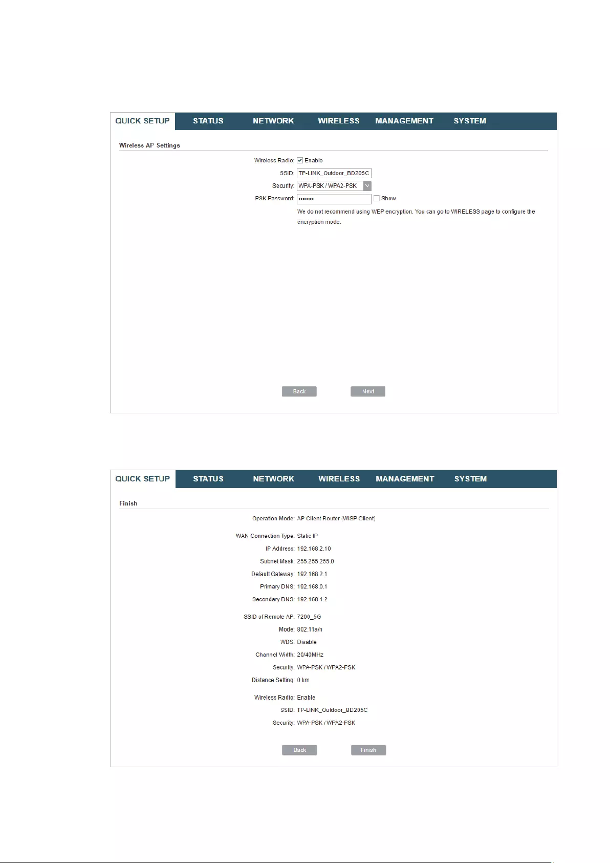
6. In the Wireless AP Settings section, specify the parameters to create a new wireless
network for the downstream clients. Click
Next
.
7. In the Finish section, review the configurations and click
Finish
to complete the quick
setup.
8. Connect the device according to your network topology and use it normally.

38
3 Monitor the Network
This chapter introduces how to monitor the running status and statistics of the wireless
network, including:
3.1 View the Device Information
3.2 View the Wireless Settings
3.3 View Wireless Signal Quality
3.4 View Radio Status
3.5 View the LAN Settings
3.6 View the WAN Settings
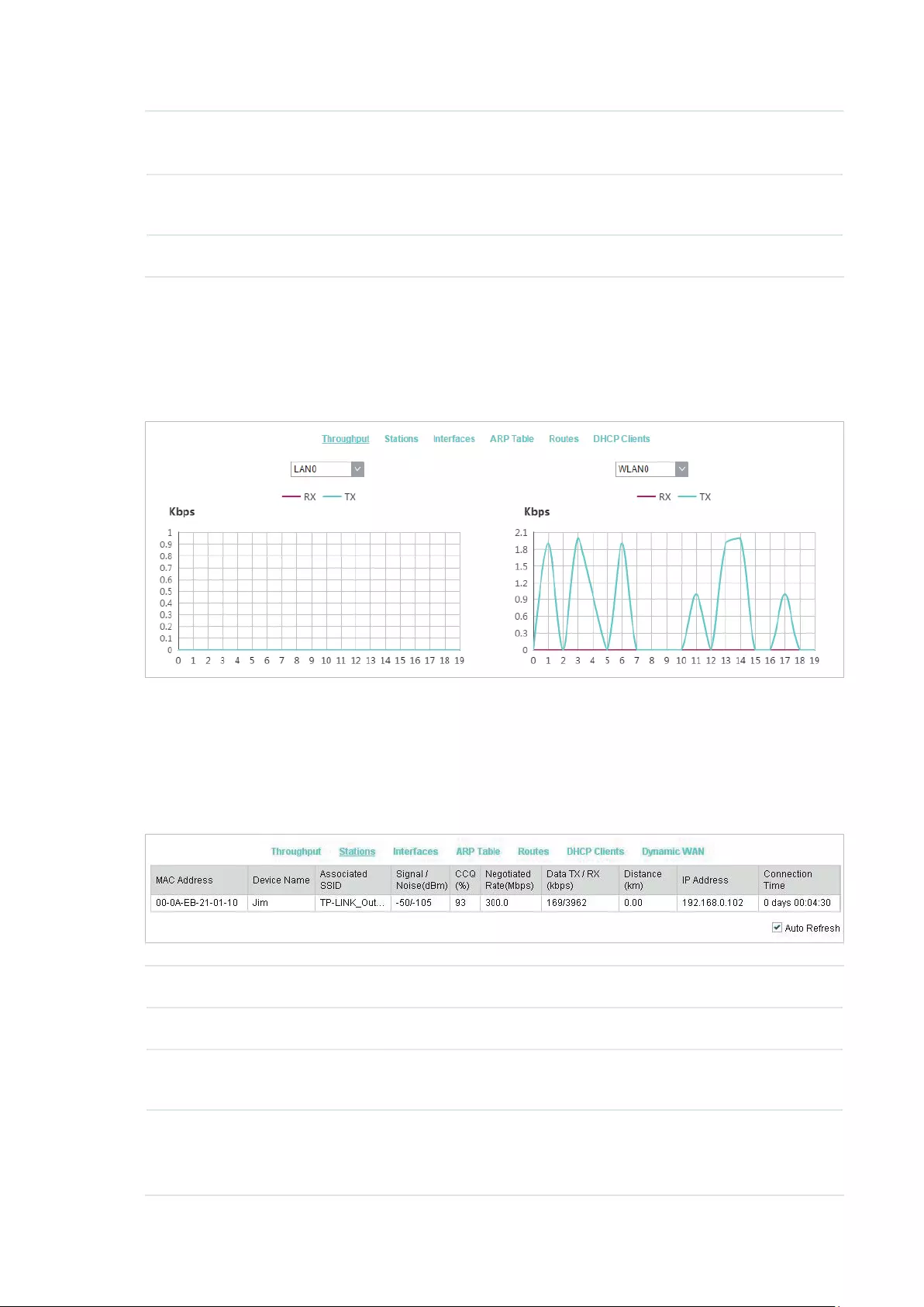
3.7 Monitor Throughput
3.8 Monitor Stations
3.9 Monitor Interfaces
3.10 Monitor ARP Table
3.11 Monitor Routes
3.12 Monitor DHCP Clients
3.13 Monitor Dynamic WAN

39
3.1 View the Device Information
Go to the STATUS page. In the Device Information section, you can view the basic
information of the device. To configure the device information, refer to
7. Configure the
System
.
Device Name Displays the name of the device. By default, it is the product model.
Device Model Displays the product model and the hardware version of the device.
Firmware
Version
Displays the current firmware version of the device.
System Time Displays the current system time.
Uptime Displays the running time of the device.
CPU Displays the CPU occupancy.
Memory Displays the memory occupancy.
3.2 View the Wireless Settings
Go to the STATUS page. In the Wireless Settings section, you can view the parameters
of the wireless network created by the device. To configure the parameters, refer to
5.
Configure the Wireless Parameters
.

40
MAXtream Displays the status of the MAXtream function. This function is only available
in Access Point mode and AP Router mode. MAXtream is a TP-Link
proprietary technology. It is based on TDMA (Time Division Multiple Access)
so that data streams are transmitted in their own time slots. MAXtream aims
to maximize throughput and minimize latency. “Hidden nodes” problem can
also be eliminated with MAXtream enabled.
Note:
MAXtream Technology is only compatible with Pharos series products.
Working with products from other manufacturer will cause network fault.
Channel/
Frequency
Displays the channel and frequency which are currently used by the device.
Channel Width Displays the channel width which is currently used by the device.
IEEE802.11
Mode
Displays the IEEE802.11 protocol currently used by the device.
Max TX Rate Displays the maximum data rate of the device during the sending of the
wireless packets.
Transmit Power Displays the transmit power which is currently used by the device.
Distance Displays the wireless coverage distance. In the coverage of the device, the
clients can be placed to get good wireless performance.
3.3 View Wireless Signal Quality
Go to the STATUS page. In the Wireless Signal Quality section, you can view the current
signal quality of the upstream wireless network. It is only applicable for the Client, Repeater
(Range Extender), Bridge and AP Client Router (WISP Client) modes.
Signal Strength
(Horizontal/
Vertical)
Displays the received wireless signal strength of the root AP.
Noise Strength Displays the received environmental noise from wireless interference on
the operating frequency.

41
SNR Displays the Signal to Noise Ratio (SNR) of the device. SNR refers to
the power ratio between the received wireless signal strength and the
environmental noise strength. The larger SNR value is, the better network
performance the device can provide.
Transmit CCQ Displays the wireless Client Connection Quality (CCQ). CCQ refers to the
ratio of effective transmission bandwidth and the actual total bandwidth. It
reflects the quality of the actual link. A larger value means a better utilization
of the bandwidth.
3.4 View Radio Status
Go to the STATUS page. In the Radio Status section, you can view the radio status of the
device.
AP Displays the status of the wireless AP function. With this enabled, the
device can provide a wireless network for the clients. By default, it is
enabled in Access Point, Repeater, Bridge, AP Router and AP Client Router
modes and disabled in Client mode.
MAC Address Displays the MAC address of the wireless interface connected to the
clients.
SSID Displays the wireless network name (SSID) created by the device.

42
Security Mode Displays the security mode you’ve selected for your wireless network.
There are three security modes: WPA-PSK, WPA and WEP. None means
that no security mode is selected and all the hosts are allowed to access
the wireless network directly.
Connected
Stations
Displays the number of the connected stations.
Client Displays the status of the wireless client function. With this function
enabled, the device can connect to the root AP through wireless
connection. By default, it is enabled in Client, Repeater, Bridge and AP Client
Router modes and disabled in Access Point and AP Router modes.
MAC Address Displays the MAC address of the wireless interface connected to the root
AP.
Security Mode Displays the security mode you’ve selected for your wireless network.
There are three security modes: WPA-PSK, WPA and WEP. The security
mode which is set on the device should be the same as that on the root AP.
WDS Displays the status of the WDS (Wireless Distribution System) function.
WDS is a communication system among multiple wireless networks . It is
established between APs through wireless connection. WDS is used during
the connection process between the device and the root AP.
Enable: Forward data frames using four address fields.
Disable: Forward data frames using three address fields.
Auto: The device automatically negotiates the wireless data frame structure
(three or four address fields) with the root AP. The selection of Auto is
recommended.
Root AP BSSID Displays the BSSID (Basic Service Set ID) of the root AP. BSSID is used to
identify a BSS. Each BSS has its own BSSID. The BSSID is decided by the
manufacturers, and it is usually related to the device’s MAC address.
Root AP SSID Displays the wireless network name of the root AP.
TX Rate Displays the data rate of the device during the sending of the wireless
packets.
RX Rate Displays the data rate of the device during the receiving of the wireless
packets.
Connection
Time
Displays the amount of time the device has been connected to the root AP.
43
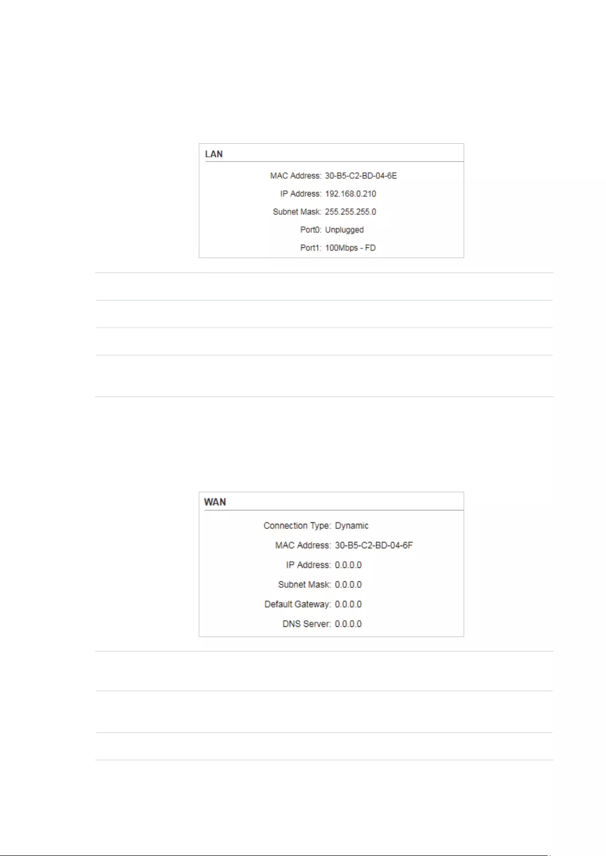
3.5 View the LAN Settings
Go to the STATUS page. In the LAN section, you can view the LAN information of the
device. To configure the LAN settings, refer to
4. Configure the Network
.
MAC Address Displays the LAN port MAC address of the device.
IP Address Displays the LAN port IP address of the device.
Subnet Mask Displays the subnet mask of the LAN.
Port Displays the current status of the LAN Ethernet port connections and the
Maximum transmission rate of the plugged port.
3.6 View the WAN Settings
Go to the STATUS page. In the WAN section, you can view the WAN information of the
device. To configure the LAN settings, refer to
4. Configure the Network
.
Connection
Type
Displays the connection type of the device.
MAC Address Displays the MAC address of the wireless interface connected to the root
AP.
IP Address Displays the IP address of the wireless interface connected to the root AP.
44
Subnet Mask Displays the subnet mask of the wireless interface connected to the root
AP.
Default
Gateway
Displays the default gateway.
DNS Server Displays the DNS server.
3.7 Monitor Throughput
Go to the STATUS page. In the Monitor section, select
Throughput
and you can monitor
the current data traffic of specified interfaces including LAN, WAN and BRIDGE.
3.8 Monitor Stations
Go to the STATUS page. In the Monitor section, select
Stations
and you can monitor the
information of all the stations that are connected to the device.
MAC Address Displays the MAC address of the station.
Device Name Displays the device name of the station.
Associated
SSID
Displays the SSID that the station is connected to.
Signal/Noise
(dBm)
Displays the signal strength and the noise strength of the wireless network.
The values of Chain0 and Chain1 can be displayed separately and can be
displayed unitedly.
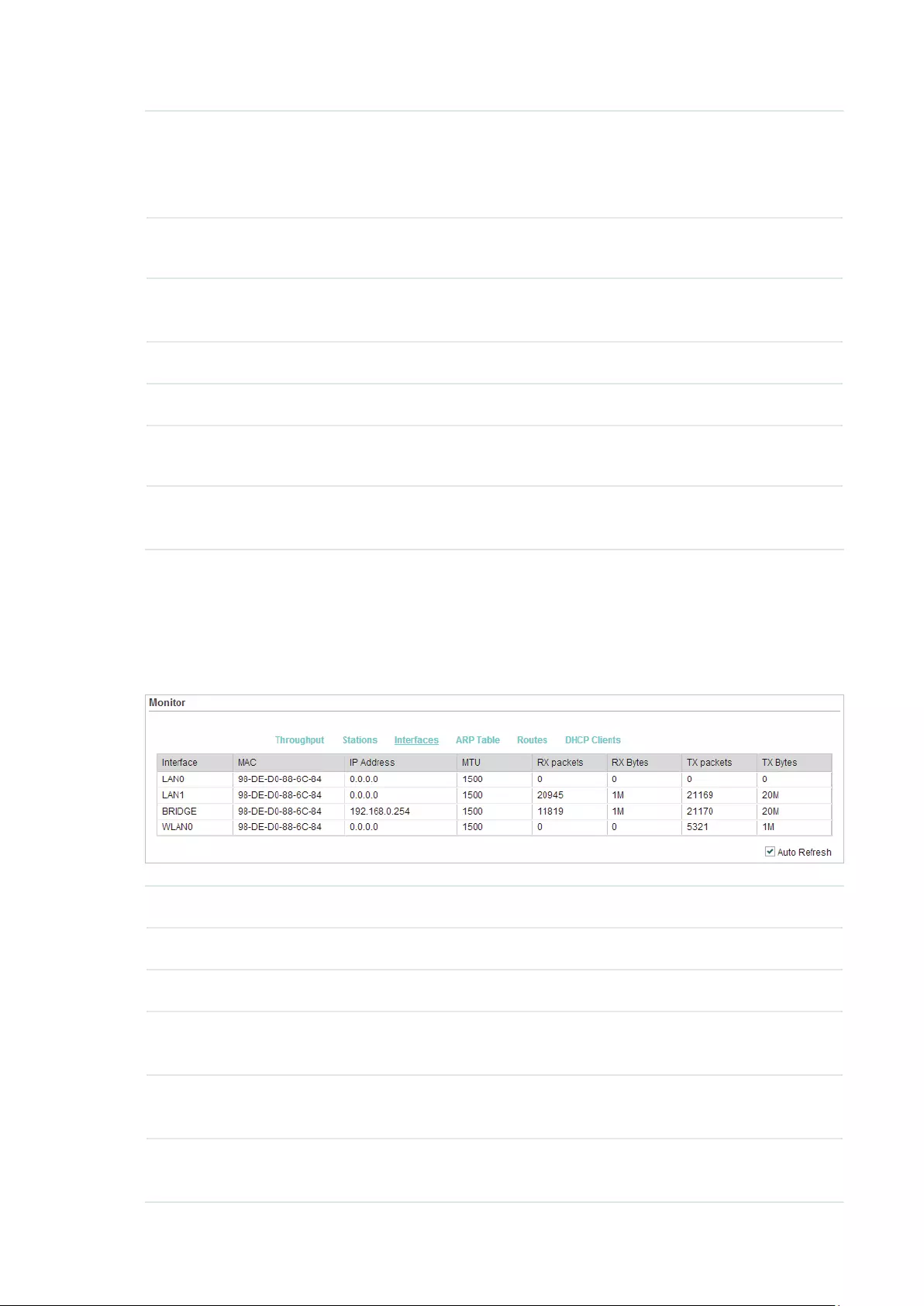
45
CCQ (%) Displays the wireless Client Connection Quality (CCQ). CCQ refers to the
ratio of effective transmission bandwidth and the actual total bandwidth. It
reflects the quality of the actual link. A larger value means a better utilization
of the bandwidth.
Negotiate Rate
(Mbps)
Displays the station’s data rates of the last transmitted packets.
Data TX/RX
(kbps)
Displays the station’s average data rates of the transmitted and received
packets over the connection time.
Distance (km) Displays the distance between the device and the station.
IP Address Displays the IP address of the station.
Connection
Time
Displays the connection duration.
Auto Refresh Enable or disable Auto Refresh. With this feature enabled, the table will
refresh automatically.
3.9 Monitor Interfaces
Go to the STATUS page. In the Monitor section, select
Interfaces
and you can monitor the
relevant information of the interfaces.
Interface Displays the interface of the device.
MAC Displays the MAC address of the interface.
IP Address Displays the IP address of the interface.
MTU Displays the Maximum Transmission Unit (MTU) of the interface. It is the
maximum packet size (in bytes) that the interface can transmit.
RX packets Displays the total amount of packets received by the interface after the
device is powered on.
RX Bytes Displays the total amount of data (in bytes) received by the interface after
the device is powered on.
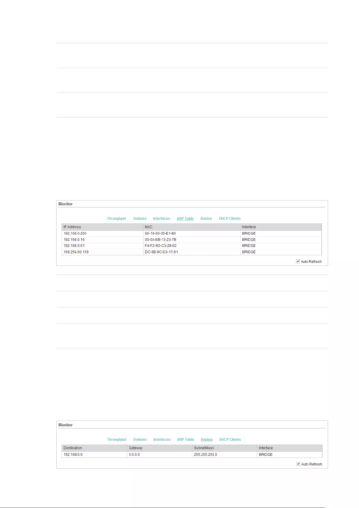
46
TX packets Displays the total amount of packets sent by the interface after the device
is powered on.
TX Bytes Displays the total amount of data (in bytes) sent by the interface after the
device is powered on.
Auto Refresh Enable or disable Auto Refresh. With this feature enabled, the table will
refresh automatically.
3.10 Monitor ARP Table
Go to the STATUS page. In the Monitor section, select
ARP Table
and you can monitor the
ARP (Address Resolution Protocol) information recorded by the device.
ARP is used to associate each IP address to the unique hardware MAC address of each
device on the network.
IP Address Displays the IP address of the corresponding ARP entry.
MAC Displays the MAC address of the corresponding ARP entry.
Interface Displays the interface connected to the device.
Auto Refresh Enable or disable Auto Refresh. With this feature enabled, the table will
refresh automatically.
3.11 Monitor Routes
Go to the STATUS page. In the Monitor section, select
Routes
and you can monitor the
routing entries recorded by the device.
Routing table is used for the device to decide the interface to forward the packets.

47
Destination Displays the IP address of the destination device or destination network.
Gateway Displays the IP address of the appropriate gateway.
SubnetMask Displays the Subnet Mask of the destination network.
Interface Displays the interface that the destination device is on.
Auto Refresh Enable or disable Auto Refresh. With this feature enabled, the table will
refresh automatically.
3.12 Monitor DHCP Clients
Go to the STATUS page. In the Monitor section, select
DHCP Clients
and you can monitor
the information of all the DHCP clients.
Client Name Displays the device name of the client.
MAC Address Displays the MAC address of the client.
Assigned IP Displays the IP address that the device assigned to the client.
Lease Time Displays the time that the client leased. When the time expires, the clients
will request to renew the lease automatically.
Auto Refresh Enable or disable Auto Refresh. With this feature enabled, the table will
refresh automatically.
3.13 Monitor Dynamic WAN
Note:
Dynamic WAN submenu is only available in AP Router mode and AP client Router (WISP client) mode
when the WAN connection type is PPPoE, PPTP, L2TP or Dynamic.

48
Go to the STATUS page. In the Monitor section, select
Dynamic WAN
and you can monitor
the WAN connection status of the device.
Status Displays the status of the WAN connection.
IP Address Displays the IP address of the WAN.
Subnet Mask Displays the subnet mask of the WAN.
Gateway IP Displays the gateway address of the device.
Primary DNS Displays the primary DNS of the device.
Secondary DNS Displays the secondary DNS of the device.
Connection
UPtime
Displays the time that the latest WAN connection lasts.
Obtain Click
Obtain
to obtain the WAN IP address from the upstream device.
Release Click
Release
to release the WAN IP address.
Auto Refresh Enable or disable Auto Refresh. With this feature enabled, the table will
refresh automatically.

49
4 Congure the Network
This chapter introduces how to configure the network parameters and the advanced
features, including:
4.1 Configure WAN Parameters
4.2 Configure LAN Parameters
4.3 Configure Management VLAN
4.4 Configure the Forwarding Feature
4.5 Configure the Security Feature
4.6 Configure Access Control
4.7 Configure Static Routing
4.8 Configure Bandwidth Control
4.9 Configure IP & MAC Binding

50
4.1 Configure WAN Parameters
Note:
WAN submenu is only available in AP Router mode and AP client Router (WISP client) mode.
WAN submenu is used to create the WAN connection and configure the related advanced
parameters.
Go to the Network page. In the WAN section, configure the WAN parameters of the device.
Follow the steps below to configure the WAN parameters:
1. Select the connection type according to your need. The device supports five types:
Static, Dynamic, PPPoE, L2TP, and PPTP.
Static
This connection type uses a permanent, fixed (static) IP address that is assigned by
your ISP. In this type, you should fill in the IP address, Netmask, Gateway IP, and DNS IP
address manually, which are assigned by your ISP.
IP address Enter the IP address provided by your ISP.
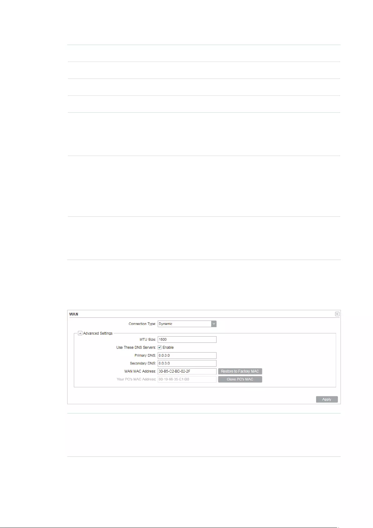
51
Netmask Enter the netmask provided by your ISP. Normally use 255.255.255.0.
Gateway IP Enter the gateway IP address provided by your ISP.
Primary DNS Enter the DNS IP address provided by your ISP.
Secondary DNS Enter alternative DNS IP address if your ISP provides it.
MTU Size The normal MTU (Maximum Transmission Unit) value for most Ethernet
networks is 1500 Bytes. For some ISPs you need to modify the MTU. But
this is rarely required, and should not be done unless you are sure it is
necessary for your ISP connection.
WAN MAC
Address
Specify the MAC address of WAN interface. This field displays the
current MAC address of the WAN port. If your ISP requires that you
register the MAC address, enter the correct MAC address into this
field. The format for the MAC Address is XX-XX-XX-XX-XX-XX (X is
any hexadecimal digit). Click
Restore Factory MAC
to restore the MAC
address of WAN port to the factory default value.
Your PC’s MAC
Address
Displays the MAC address of the PC that is managing the router. Some
ISPs require that you should register the MAC address of your PC. If the
MAC address is required, you can click
Clone PC’s MAC
to set the WAN
MAC address the same as your management PC’s MAC address.
Dynamic
For this connection, your ISP uses a DHCP server to assign your router an IP address
for connecting to the internet. You don’t need to configure any parameters.
MTU Size Specify the MTU size. The normal MTU (Maximum Transmission Unit)
value for most Ethernet networks is 1500 Bytes. For some ISPs you need
to modify the MTU. But this is rarely required, and should not be done
unless you are sure it is necessary for your ISP connection.

52
Use These DNS
Servers
If your ISP gives you one or two DNS IP addresses, select Use These
DNS Servers and enter the Primary DNS and Secondary DNS into the
correct fields. Otherwise, the DNS servers will be assigned from ISP
dynamically.
Primary DNS Enter the DNS IP address provided by your ISP.
Secondary DNS Enter another DNS IP address provided by your ISP.
WAN MAC
Address
Specify the WAN MAC address. This field displays the current MAC
address of the WAN port. If your ISP binds the MAC address of your
previous computer/router, enter the correct MAC address into this
field. The format for the MAC Address is XX-XX-XX-XX-XX-XX (X is
any hexadecimal digit). Click
Restore Factory MAC
to restore the MAC
address of WAN port to the factory default value.
Your PC’s MAC
Address
Displays the MAC address of the PC that is managing the router. Some
ISPs require that you should register the MAC address of your PC. If the
MAC address is required, you can click
Clone PC’s MAC
to set the WAN
MAC address the same as your management PC’s MAC address.
PPPoE
If your ISP delivers internet through phone line and provides you with username and
password, you should choose this type. Under this condition, you should fill in both User
Name and Password that the ISP supplied. Note that these fields are case-sensitive.
User Name Enter the User Name that is provided by your ISP.
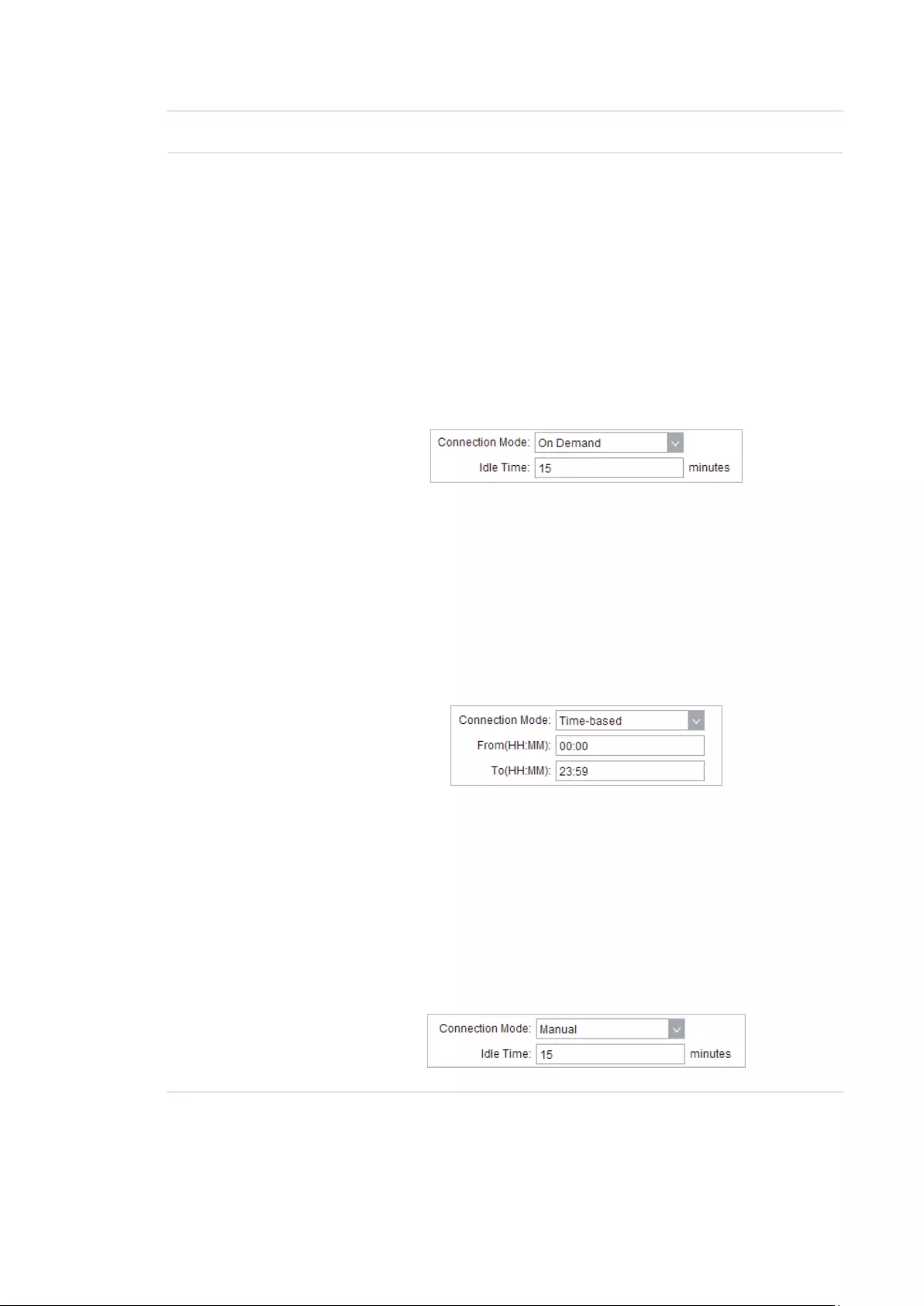
53
Password Enter the Password that is provided by your ISP.
Connection
Mode
Select the Connection Mode.
·On Demand
You can configure the device to disconnect your internet connection
after a specified period of inactivity (Idle Time). If your internet
connection has been terminated due to inactivity, Connection on
Demand enables the device to automatically re-establish your
connection when you attempt to access the internet again. The
default Idle Time is 15 minutes. If your internet connection is
expected to remain active all the time, enter 0 in the Idle Time field.
Users those pay by time for their internet access can choose this
mode to save their internet-access fee.
·Automatic
Connect automatically after the device is disconnected. Users those
are charged a flat monthly fee can choose this mode.
·Time-based
You can configure the device to make it connect or disconnect based
on time. Enter the start time in From (HH:MM) for connecting and end
time in To (HH:MM) for disconnecting. Users those need to control
the time period of internet access can choose this mode.
·Manual
You can configure the device to make it connect or disconnect
manually. After a specified period of inactivity (Idle Time), the device
will disconnect your internet connection, and you must click
Connect
manually to access the internet again. If your internet connection
is expected to remain active all the times, enter 0 in the Idle Time
field. Otherwise, enter the desired Idle Time in minutes you wish to
use. Users charged by time for their internet access can choose this
mode to save their internet-access fee.

54
Second
Connection
If your ISP provides an extra Connection type such as Dynamic/Static
IP to connect to a local area network, you can activate this secondary
connection.
Disable: The Secondary Connection is disabled by default, so there is
PPPoE connection only. This is recommended.
Dynamic IP: Use dynamic IP address to connect to the local area
network provided by ISP.
Static IP: Use static IP address to connect to the local area network
provided by ISP.
MTU Size Specify the MTU size. The default MTU (Maximum Transmission Unit)
size is 1480 bytes, which is usually appropriate. For some ISPs, you need
modify the MTU. This should not be done unless your ISP told you to.
Service Name Specify the Service Name provided by your ISP. Please keep it empty if
your ISP doesn’t provide the name.
AC Name Specify the AC Name provided by your ISP. Please keep it empty if your
ISP doesn’t provide the name.
Detect Internal Specify the Detect Interval. The default value is 0. You can input the
value between 0 and 120. The device will detect Access Concentrator
online every interval seconds. If the value is 0, it means not detecting.
Use ISP-
specified IP
If your service provider provides you with an IP address along with the
user name and password, Enable «Use ISP-specified IP» and enter the IP
address.
Use These DNS
Servers
If the ISP provides a DNS server IP address for you, Enable Use These
DNS Server, and fill the Primary DNS and Secondary DNS fields below.
Otherwise, the DNS servers will obtain automatically from ISP.
WAN MAC
Address
Specify the WAN MAC address. This field displays the current MAC
address of the WAN port. If your ISP binds the MAC address of your
previous computer/router, enter the correct MAC address into this
field. The format for the MAC Address is XX-XX-XX-XX-XX-XX (X is
any hexadecimal digit). Click
Restore Factory MAC
to restore the MAC
address of WAN port to the factory default value.
Your PC’s MAC
Address
Displays the MAC address of the PC that is managing the router. You
can click
Clone PC’s MAC
to set the WAN MAC address the same as
your management PC’s MAC address.
Restore to
Factory MAC
Click this button to restore the WAN MAC address as factory MAC
address.
Clone PC’s MAC Click this button to set the WAN MAC address as PC’s MAC address.
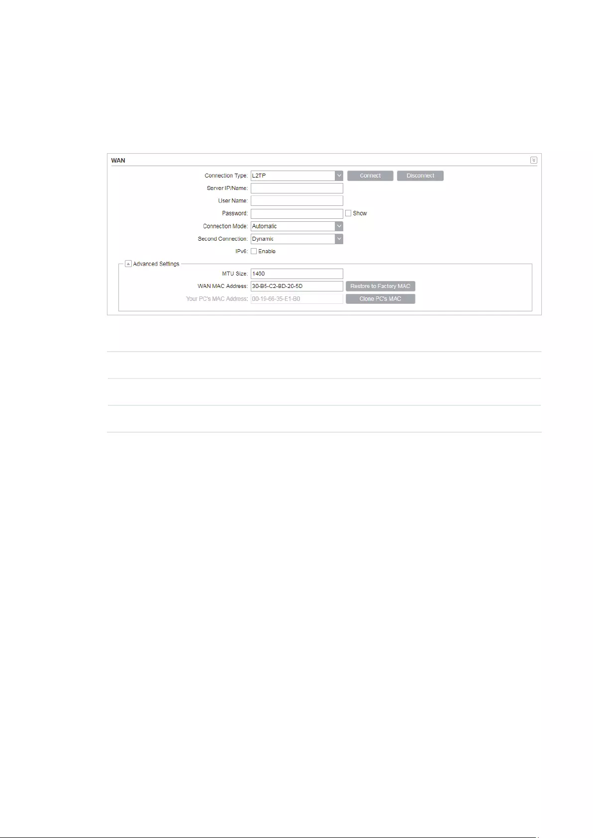
55
L2TP/PPTP
If your ISP supplies internet access through L2TP or PPTP, it will provide the following
parameters. The configurations of L2TP and PPTP are the same, and the following
introduction takes L2TP as an example.
Specify the parameters below and click
Connect
:
Server IP/Name Enter the server IP address or the domain name provided by your ISP.
User Name Enter the User Name provided by your ISP. This field is case-sensitive.
Password Enter the Password provided by your ISP. This field is case-sensitive.

56
Connection
Mode
Select the Connection Mode.
·On Demand
You can configure the device to disconnect your internet connection
after a specified period of inactivity (Idle Time). If your internet
connection has been terminated due to inactivity, Connection on
Demand enables the device to automatically re-establish your
connection when you attempt to access the internet again. The
default Idle Time is 15 minutes. If your internet connection is
expected to remain active all the time, enter 0 in the Idle Time field.
Users those pay by time for their internet access can choose this
mode to save their internet-access fee.
·Automatic
Connect automatically after the device is disconnected. Users those
are charged a flat monthly fee can choose this mode.
·Manual
You can configure the device to make it connect or disconnect
manually. After a specified period of inactivity (Idle Time), the device
will disconnect your internet connection, and you must click
Connect
manually to access the internet again. If your internet connection
is expected to remain active all the times, enter 0 in the Idle Time
field. Otherwise, enter the desired Idle Time in minutes you wish to
use. Users charged by time for their internet access can choose this
mode to save their internet-access fee.
Second
Connection
If your ISP provides a Connection type such as Dynamic/Static IP
to connect to a local area network, you can activate this secondary
connection.
Dynamic IP: Use dynamic IP address to connect to the local area
network provided by ISP.
Static IP: Use static IP address to connect to the local area network
provided by ISP.
MTU Size Specify the MTU size. The normal MTU (Maximum Transmission Unit)
value for most Ethernet networks is 1500 Bytes. For some ISPs you need
to modify the MTU. But this is rarely required, and should not be done
unless you are sure it is necessary for your ISP connection.
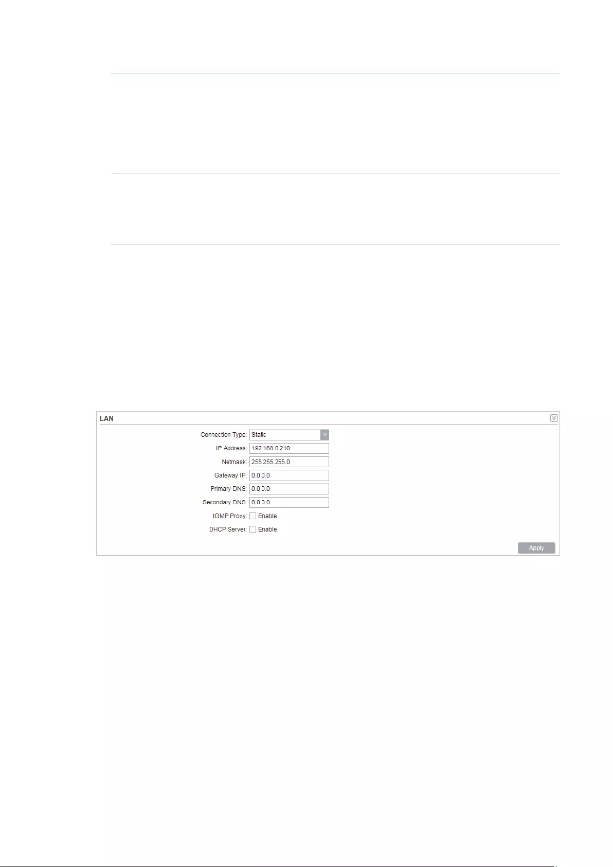
57
WAN MAC
Address
Specify the WAN MAC address. This field displays the current MAC
address of the WAN port. If your ISP requires that you register the MAC
address, enter the correct MAC address into this field. The format for
the MAC Address is XX-XX-XX-XX-XX-XX (X is any hexadecimal digit).
Click
Restore Factory MAC
to restore the MAC address of WAN port to
the factory default value.
Your PC’s MAC
Address
Displays the MAC address of the PC that is managing the router. Some
ISPs require that you should register the MAC address of your PC. If the
MAC address is required, you can click
Clone PC’s MAC
to set the WAN
MAC address the same as your management PC’s MAC.
2. Click
Apply
, then click
Save
.
4.2 Configure LAN Parameters
LAN submenu is used to configure the LAN parameters for the device and the clients.
Access Point/Client/Repeater/Bridge Mode
Go to the Network page. In the LAN section, configure the following parameters.
Follow the steps below to configure the LAN parameters:
1. Select the connection type according to your need. The device supports two types:
Static and Dynamic.
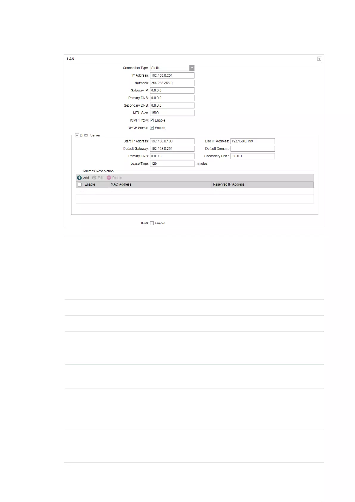
58
Static
IP address Enter the LAN IP address of your device. By default, it is 192.168.0.254.
Note:
When you change the LAN IP address in the Network tab, you should log
in with the new IP address and save the settings for the configuration
change to take effect. Otherwise the configuration will be lost after the
reboot.
Netmask Enter the Netmask provided by your ISP. Normally use 255.255.255.0.
Gateway IP Enter the gateway IP address for your device.
Primary DNS Enter the primary DNS IP address provided by your ISP. Please consult
your ISP if you don’t know the DNS value. The factory default setting is
0.0.0.0.
Secondary DNS Enter the secondary DNS IP address of alternative DNS server if your
ISP two DNS servers. The factory default setting is 0.0.0.0.
MTU Size Specify the MTU size. The normal MTU (Maximum Transmission Unit)
value for most Ethernet networks is 1500 Bytes. For some ISPs you need
to modify the MTU. But this is rarely required, and should not be done
unless you are sure it is necessary for your ISP connection.
IGMP Proxy Enable or disable IGMP (Internet Group Management Protocol) Proxy.
IGMP proxy is used to process the multicast stream in the netwok. It
normally works for IPTV service.

59
DHCP Server Enable or disable the DHCP server function. With this function enabled,
the build-in DHCP server will assign IP address to the clients connected
to the device.
Start IP Address Specify the first IP address of the IP address pool. By default, it is
192.168.0.100.
End IP Address Specify the last IP address of the IP address pool. By default, it is
192.168.0.199.
Default
Gateway
Specify the gateway IP address for the LAN network. By default, it is
192.168.0.254.
Default Domain (Optional) Specify the domain name for the DHCP server.
Primary DNS Enter the DNS IP address for the LAN. By default,it is 0.0.0.0.
Secondary DNS Enter the IP address of alternative DNS server if there are two DNS
servers. By default, it is 0.0.0.0.
Lease Time Enter the amount time of the leased IP address assigned by the DHCP
server. When the time expires, the clients will request to renew the lease
automatically.
Address
Reservation
Enable Address Reservation and you can specify a reserved IP address
for a PC on the local area network, so the PC will always obtain the same
IP address each time when it starts up. Reserved IP addresses could be
assigned to servers that require permanent IP settings.
To configure Address Reservation:
Click
Add
, specify the MAC address and the IP address. Enable this
entry, then click
Save
.
Dynamic

60
Fallback IP Enable or disable the Fallback IP. When the device doesn’t find DHCP
server, it will use the fallback IP as the LAN IP address.
DHCP Fallback
IP
Specify the fallback IP for the device. By default, it is 192.168.0.254.
DHCP Fallback
Mask
Specify the fallback netmask for the device.
Primary DNS Enter the DNS IP address for the LAN. By default, it is 0.0.0.0.
Secondary DNS Enter the IP address of alternative DNS server if there are two DNS
servers. By default, it is 0.0.0.0.
IGMP Proxy Enable or disable IGMP (Internet Group Management Protocol) Proxy.
IGMP proxy is used to process the multicast stream in the network. It
normally works for IPTV service.
2. Click
Apply
, then click
Save
.
AP Router/AP Client Router Mode
Go to the Network page. In the LAN section, configure the following parameters.
1. For LAN connection type, the device only supports Static.

61
IP address Enter the LAN IP address of your device. By default, it is 192.168.0.254.
Note:
When you change the LAN IP address in the Network tab, you should log
in with the new IP address and save the settings for the configuration
change to take effect. Otherwise the configuration will be lost after the
reboot.
Netmask Enter the Netmask provided by your ISP. Normally use 255.255.255.0.
IGMP Proxy Enable or disable IGMP (Internet Group Management Protocol) Proxy.
IGMP proxy is used to process the multicast stream in the netwok. It
normally works for IPTV service.
DHCP Server Enable or disable the DHCP server function. With this function enabled,
the build-in DHCP server will assign IP address to the clients connected
to the device.
Start IP Address Specify the first IP address of the IP address pool. By default, it is
192.168.0.100.
End IP Address Specify the last IP address of the IP address pool. By default, it is
192.168.0.199.
Default
Gateway
Specify the gateway IP address for the LAN network. By default, it is
192.168.0.254.
Default Domain (Optional) Specify the domain name for the DHCP server.
Primary DNS Enter the DNS IP address for the LAN. By default,it is 0.0.0.0.
Secondary DNS Enter the IP address of alternative DNS server if there are two DNS
servers. By default, it is 0.0.0.0.
Lease Time Enter the amount time of the leased IP address assigned by the DHCP
server. When the time expires, the clients will request to renew the lease
automatically.
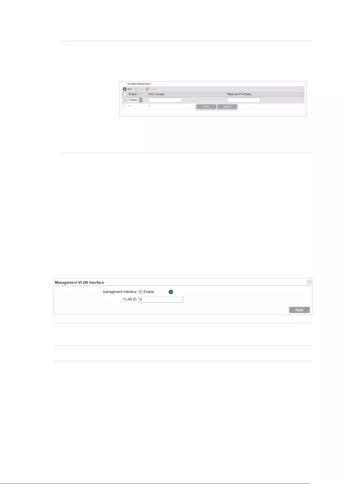
62
Address
Reservation
Enable Address Reservation and you can specify a reserved IP address
for a PC on the local area network, so the PC will always obtain the same
IP address each time when it starts up. Reserved IP addresses could be
assigned to servers that require permanent IP settings.
To configure Address Reservation:
Click
Add
, specify the MAC address and the IP address. Enable this
entry, then click
Save
.
2. Click
Apply
, then click
Save
.
4.3 Configure Management VLAN
Management VLAN provides a safer way for you to manage the device. With Management
VLAN enabled, only the hosts in the management VLAN can manage the device. Since
most hosts cannot process VLAN tags, connect the management host to the network via
a switch, and set up correct VLAN settings to ensure the communication between the host
and the device in the management VLAN.
Go to the Network page. In the Management VLAN Interfaces section, enable the
Management VLAN function, specify
VLAN ID
and click
Apply
. Then click
Save
.
Management
VLAN
Enable or disable the Management VLAN function. By default, it is disabled.
VLAN ID Specify the Management VLAN ID. The valid values are from 2 to 4094.
4.4 Configure the Forwarding Feature
Note:
Forwarding submenu is only available in AP Router mode and AP client Router (WISP client) mode.
The IP address used on the internet is public IP address, while IP address used on local
area network is private IP address. The hosts using private IP addresses cannot access
the internet directly and vice versa.

63
The hosts using private IP addresses visit internet through NAT (Network Address
Translation) technology. NAT can transfer private IP addresses into public IP addresses to
realize the communication from internal hosts to external hosts.
If the hosts on the internet want to visit the hosts on local area network, the forwarding
function should be used, including DMZ, Virtual server, Port triggering and UPnP.
Go to the Network page. In the Forwarding section, configure the following parameters
and click
Apply
. Then click
Save
.
DMZ Enable or disable the DMZ function. DMZ (Demilitarized Zone) specifically
allows one computer/device behind NAT to become “demilitarized”, so all
packets from the external network are forwarded to this computer/device.
The demilitarized host is exposed to the wide area network, which can
realize the unlimited bidirectional communication between internal hosts
and external hosts.
DMZ IP Specify the IP address of the local host network device. The DMZ host
device will be completely exposed to the external network. Any PC that was
used for a DMZ must have a static or reserved IP Address because its IP
Address may change when using the DHCP function.
ALG Select the type of ALG to enable the corresponding feature. Common
NAT only translates the address of packets at network layer and the port
number at transport layer but cannot deal with the packets with embedded
source/destination information in the application layer. Application layer
gateway (ALG) can deal with protocols with embedded source/destination
information in the application payload. Some protocols such as FTP, TFTP,
H323 and RTSP require ALG (Application Layer Gateway) support to pass
through NAT.
FTP ALG: Allows FTP clients and servers to transfer data across NAT.
TFTP ALG: Allows TFTP clients and servers to transfer data across NAT.
H323 ALG: Allows Microsoft NetMeeting clients to communicate across
NAT.
RTSP ALG: Allows some media player clients to communicate with some
streaming media servers across NAT.

64
Virtual Server Enable or disable Virtual Server. Virtual servers can be used for setting up
public services on your local area network, such as DNS, Email and FTP. A
virtual server is defined as a service port, and all requests from the internet
to this service port will be redirected to the LAN server. Virtual Server
function not only makes the users from internet visit the local area network,
but also keeps network security within the intranet as other services are
still invisible from internet. The LAN server must have a static or reserved
IP Address because its IP Address may change when using the DHCP
function.
To configure Virtual Server:
Click
Add
, specify the following parameters and
Enable
the entry. Click
Save
.
IP: Enter the IP Address of the PC providing the service application.
Internal Port: Enter the Internal Port number of the PC running the service
application. You can leave it blank if the Internal Port is the same as the
Service Port, or enter a specific port number.
Service Port: Enter the numbers of external Service Port. You can type a
service port or a range of service ports (the format is XXX – YYY, XXX is the
start port, YYY is the end port). Internet users send request to the port for
services.
Protocol: Choose the one of the protocols used for this application: TCP,
UDP, or TCP/UDP.

65
Port Trigger Enable or disable port trigger. Due to the existence of the firewall, some
applications such as online games, video conferences, VoIPs and P2P
downloads need the device to configure the forwarding to work properly,
and these applications require multiple ports connection, for single-port
virtual server cannot meet the demand. Port trigger function comes at this
time. When an application initiates a connection to the trigger port, all the
incoming ports will open for subsequent connections.
To configure port trigger:
Click
Add
, specify the following parameters and
Enable
the entry. Click
Save
.
Incoming Port: Enter the incoming port for incoming traffic. The port or
port range is used by the remote system when it responds to the outgoing
request. A response to one of these ports will be forwarded to the PC that
triggered this rule. You can input at most 5 groups of ports (or port section).
Every group of ports must be set apart with “,”. For example, 2000-2038,
2050-2051, 2085, 3010-3030.
Trigger Port: Enter the trigger port for outgoing traffic. An outgoing
connection using this port will “Trigger” this rule.
Protocol: Choose the one of the protocols used for this application: TCP,
UDP, or TCP/UDP.

66
UPnP Enable or disable UPnP. If you use applications such as multiplayer
gaming, peer-to-peer connections, or real-time communications such
as instant messaging or remote assistance (a feature in Windows XP),
you should enable the UPnP function. The Universal Plug and Play (UPnP)
function allows the devices, such as internet computers, to access the
local host resources or devices as needed. Host in the local area network
can automatically open the corresponding ports on a router, and make
the application of external host access the resources of the internal host
through the opened ports. Therefore, the functions limited to the NAT
can work properly. Compared to virtual server and port triggering, the
application of UPnP doesn’t need manual settings. It is more convenient for
some applications required unfixed ports.
App Description: Displays the description provided by the application in
the UPnP request.
External Port: Displays the external port number that the router opened for
the service application.
Protocol: Displays which type of protocol is opened.
Internal Port: Displays the internal service port number of the local host
running the service application.
IP Address: Displays the IP address of the local host which initiates the
UPnP request.
Status: Enabled means that port is still active. Otherwise, the port is
inactive.
4.5 Configure the Security Feature
Note:
Security submenu is only available in AP Router mode and AP client Router (WISP client) mode.
Stateful Packet Inspection (SPI) is a firewall that keeps track of the state of network
connections (such as TCP streams, UDP communication) traveling across it. The firewall
is programmed to distinguish legitimate packets for different types of connections. Only
packets matching a known active connection will be allowed to pass through by the
firewall and others will be rejected. SPI Firewall is enabled by factory default.

67
1. Go to the Network page. In the Security > Basic section, configure the following
parameters and click
Apply
.
SPI Firewall Check the Enable box to use the SPI Firewall function. If forwarding
rules are enabled at the same time, the device will give priority to meet
forwarding rules.
Ping Select and enable the ping forbidden function.
WAN Ping Forbidden: Enable or disable this function. With this option
enabled, the device will not reply the ping request originates from
internet. By default, it is disabled.
LAN Ping Forbidden: Enable or disable this function. With this option
enabled, the device will not reply the ping request originates from local
network.
VPN Select and enable the VPN function.
A VPN is created by establishing a virtual point-to-point connection
through the use of dedicated connections, virtual tunneling protocols, or
traffic encryptions. Through VPN you can access your private network
over internet. A virtual private network connection across the internet
is similar to a wide area network (WAN) link between sites. From a user
perspective, the extended network resources are accessed in the same
way as resources available within the private network. When hosts in the
local area network want to visit the remote virtual private network using
virtual tunneling protocols, the corresponding VPN protocol should be
enabled.
PPTP Passthrough: PPTP (Point-to-Point Tunneling Protocol) allows
the Point-to-Point Protocol (PPP) to be tunneled through an IP (Internet
Protocol) network. Check the box to allow PPTP tunnels to pass through
the Device.
L2TP Passthrough: L2TP (Layer Two Tunneling Protocol) is the method
used to enable Point-to-Point connections via the internet on the Layer
Two level. Check the box to allow L2TP tunnels to pass through the
Device.
IPSec Passthrough: IPSec (Internet Protocol Security) is a suite of
protocols for ensuring private, secure communications over IP (Internet
Protocol) networks, through the use of cryptographic security services.
Check the box to allow IPSec tunnels to pass through the Device.

68
2. In the Security > Advanced Settings section, configure the following parameters and
click
Apply
.
DoS Protection Enable the DoS Protection and specify the parameters.
DoS (Denial of Service) Attack is to occupy the network bandwidth
maliciously by the network attackers or the evil programs sending a
lot of service requests to the Host, which incurs an abnormal service
or even breakdown of the network. With DoS Protection function
enabled, the device can analyze the specific fields of the IP packets
and distinguish the malicious DoS attack packets. Upon detecting the
packets, the device will discard the illegal packets directly and limit the
transmission rate of the legal packets if the over legal packets may
incur a breakdown of the network. The hosts sending these packets will
be added into the
Blocked DoS Host
List. The device can defend a few
types of DoS attack such as ICMP_FLOOD, UDP_FLOOD and TCP_SYN_
FLOOD.
Packets Statistics Interval: Select a value between 5 and 60 seconds
from the drop-down list. The default value is 10. The value indicates the
time interval of the packets statistics. The result of the statistic is used
for analysis by ICMP-Flood, UDP Flood and TCP-SYN Flood.
ICMP_FLOOD Attack Filter: Enter a value between 5 and 3600. The
default value is 50. When the current ICMP-FLOOD Packets number
is beyond the set value, the device will start up the blocking function
immediately.
UDP_FLOOD Attack Filter: Enter a value between 5 and 3600. The
default value is 500. When the current UPD-FLOOD Packets number
is beyond the set value, the device will start up the blocking function
immediately.
TCP_SYN_FLOOD Attack Filter: Enter a value between 5 and 3600.
The default value is 50. When the current TCP-SYN-FLOOD Packets
numbers is beyond the set value, the Device will start up the blocking
function immediately.
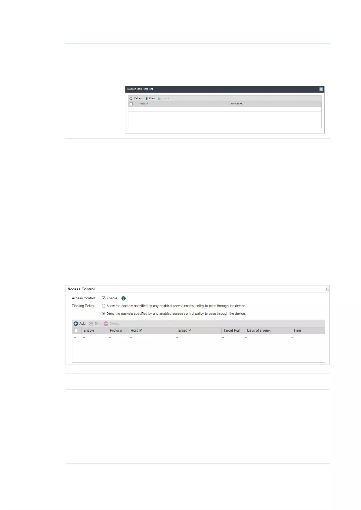
69
Blocked DoS
Host List
Click
Blocked DoS Host List
to display the blocked DoS host table
including host IP and host MAC. Click
Refresh
to renewal the table list.
Click
Clear
to release all the blocked hosts. If you want to release one or
some of the blocked hosts, select them and Click
Unlock
.
3. Click
Save
.
4.6 Configure Access Control
Note:
Access Control submenu is only available in AP Router mode and AP client Router (WISP client)
mode.
The function can be used to control the internet activities of hosts in the local area
network. For example, the online time limit and the specified web stations to visit can be
controlled by the filtering policy.
1. Go to the Network page. In the Access Control section, enable Access Control and
select the Filtering Policy.
Access Control Enable or disable Access Control.
Filtering Policy Select the filtering policy according to your need.
Allow the packets specified by any enabled access control policy to
pass through the Device: The hosts listed below are allowed to access
the internet under the rules. While others are forbidden to access.
Deny the packets specified by any enabled access control policy
to pass through the Device: The hosts listed below are forbidden to
access the internet under the rules. While others are allowed to access.

70
2. Click
Add
and create the filtering entries.
Enable Enable or disable the desired entry.
Protocol Choose one of the protocols from the drop-down list used for the target,
any of IP, TCP, UDP, or ICMP.
Host IP Enter the IP address or address range of the hosts that you need to
control, for example 192.168.0.12-192.168.0.25.
Target IP Enter the IP address or address range of the targets that you need to
control, for example 192.168.3.12-192.168.3.25.
Target Port Specify the port or port range for the target when protocol is TCP or
UDP.
Days of a week Specify the days in which the rules take effect.
Time Enter the time rule in HH:MM-HH:MM format, the default value is 00:00-
24:00.
3. Click
Save
and click
Apply
, then click
Save
.
4.7 Configure Static Routing
Note:
Static Routing submenu is only available in AP Router mode and AP client Router (WISP client)
mode.
A static route is a pre-determined path that network information must travel to reach a
specific host or network. If static route is used properly in the network, it can decrease the
network overhead and improve the speed of forwarding packets.
Static routing is generally suitable for simple network environment, in which users clearly
understand the topology of the network so as to set the routing information correctly.
When the network topology is complicated and users are not so familiar with the
topology structure, this function should be used with caution or under the guidance of the
experienced administrator.

71
1. Go to the Network page. In the Static Routing section, click
Add
and specify the
following parameters.
Enable Enable or disable the desired entry.
Target Network
IP
Enter the Target Network IP, the address of the network or host to be
visited. The IP address cannot be on the same network segment with the
device’s WAN or LAN port.
Netmask Specify the netmask for the desired entry.
Gateway IP Enter the Gateway IP, the address of the gateway that allows for contact
between the Device and the network or host
2. Click
Save
and click
Apply
, then click
Save
.
4.8 Configure Bandwidth Control
Note:
Bandwidth Control submenu is only available in AP Router mode and AP client Router (WISP client)
mode.
Bandwidth control function is used to control the internet bandwidth in the local area
network. In the case of insufficient bandwidth resources, enable the function to make the
device allocate reasonable bandwidth to the clients and achieve the purpose of efficient
use of the existing bandwidth. Via IP bandwidth control function, you can set the upper
and lower limit in the bandwidth of the computer network and guarantee a smooth sharing
network.

72
1. Go to the Network page. In the Bandwidth Control section, enable the Bandwidth
Control function.
Total Ingress
Bandwidth
Specify the upper bandwidth for receiving packets from the WAN port.
The maximum value is 100,000kbps.
Total Egress
Bandwidth
Specify the upper bandwidth for sending packets from the WAN port.
The maximum value is 100,000kbps.
2. Click
Add
and specify the following parameters.
Enable Enable or disable the desired entry.
IP Range Enter the IP Range of the target hosts which need to be controlled of
bandwidth, for example 192.168.0.12-192.168.0.25.
Port Range Enter the Port Range through which the target hosts visit external server,
for example 1-63258.
Protocol Choose one of the protocols used for this application: TCP, UDP, or TCP/
UDP.
Ingress Min
(kbps)
Specify the minimum ingress bandwidth for the desired entry.
Ingress Max
(kbps)
Specify the maximum ingress bandwidth for the desired entry.
Egress Min
(kbps)
Specify the minimum egress bandwidth for the desired entry.

73
Egress Max
(kbps)
Specify the maximum egress bandwidth for the desired entry.
3. Click
Save
and click
Apply
, then click
Save
.
4.9 Configure IP & MAC Binding
We can effectively prevent ARP attack and IP embezzlement by enabling the IP&MAC
binding. Within the local network, the device transmits IP packets to the certain target
identified by the MAC address. Therefore, the IP and MAC address should be one-to-
one correspondence and their corresponding relations are maintained by the ARP
table. ARP attack can use forged information to renewal the ARP table, and destroy
the corresponding relations between IP and MAC addresses, which would prevent the
communication between the device and the corresponding host. When the IP&MAC
Binding function is enabled, the IP and MAC relations in the ARP table won’t be expired and
renewed automatically, which effectively prevents the ARP attack.
Some functions such as access control and bandwidth control, are based on the IP
addresses to identify the access clients. The network administrator can allocate every
client a static IP, according to which he makes the access and bandwidth rules to control
the clients’ online behavior and the bandwidth they’ve used. Some illegal users may
change the IP address in order to get higher internet access. Enabling IP & MAC binding
function can effectively prevent the IP embezzlement.
Note:
After IP & MAC binding function is enabled, the IP bound to the MAC cannot be used by other MACs.
However this MAC can use other IPs within the same segment, which are not bounded by other
MACs, to access the network.
1. Go to the Network page. In the IP & MAC Binding section, click
Add
and specify the IP
address and MAC address.
Tips:
Click
Import
to quick import the entries in ARP table to IP & MAC Binding table. The imported
entries are disabled by default. You can select the desired entries and click
Edit
to enable it.

74
IP Enter the IP address that you want to bind with the MAC address.
MAC Enter the MAC address that you want to bind with the IP address.
2. Enable the desired entry and click
Save
. Click
Apply
, then click
Save
.

75
5 Congure the Wireless Parameters
This chapter introduces how to configure the parameters of the wireless network,
including:
5.1 Configure Basic Wireless Parameters
5.2 Configure Wireless Client Parameters
5.3 Configure Wireless AP Parameters
5.4 Configure Multi-SSID
5.5 Configure Wireless MAC Filtering
5.6 Configure Advanced Wireless Parameters
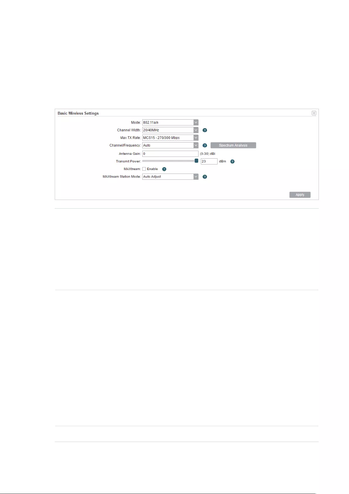
76
5.1 Configure Basic Wireless Parameters
This section allows you to configure wireless basic parameters, such as 802.11 mode,
Transmit Power, and data rates.
Go to the Wireless Page. In the Basic Wireless Settings section, configure the basic
wireless settings and click
Apply
. Then click
Save
.
Mode Select the protocol standard used in the wireless network. With a frequency
band of 2.4GHz, CPE210/CPE220/WBS210 supports five wireless modes:
802.11b, 802.11g, 802.11n, 802.11b/g and 802.11b/g/n. We recommend
you to set the mode as 11b/g/n mixed, and all of 802.11b, 802.11g and
802.11n wireless stations can connect to the device. CPE610/CPE510/
CPE520/WBS510 has a frequency band of 5GHz, supporting 802.11a,
802.11n and 802.11a/n modes. We recommend you to set the mode as
11a/n, allowing both 802.11a and 802.11n wireless stations to access the
device.
Channel Width Select the channel width of this device. Options include 5MHz, 8MHz,
10MHz, 20MHz, 30MHz, 40MHz and 20/40MHz (the device automatically
selects 20MHz/40MHz, and 20MHz will be used if 40MHz is not available).
You can select corresponding channel width according to whether their
devices support it. According to IEEE 802.11n standard, using a channel
width of 40MHz can increase wireless throughput. However, you may need
choose lower bandwidth due to the following reasons:
Increase the available number of channels within the limited total bandwidth.
To avoid interference from overlapping channels occupied by other devices
in the environment.
Lower bandwidth can concentrate higher transmit power, increasing
stability of wireless links over long distances.
Subject to the channel width of root AP in Client/ Bridge/ Repeater/ Client
Router operation modes.
Max TX Rate Set the maximum transmit data rate.
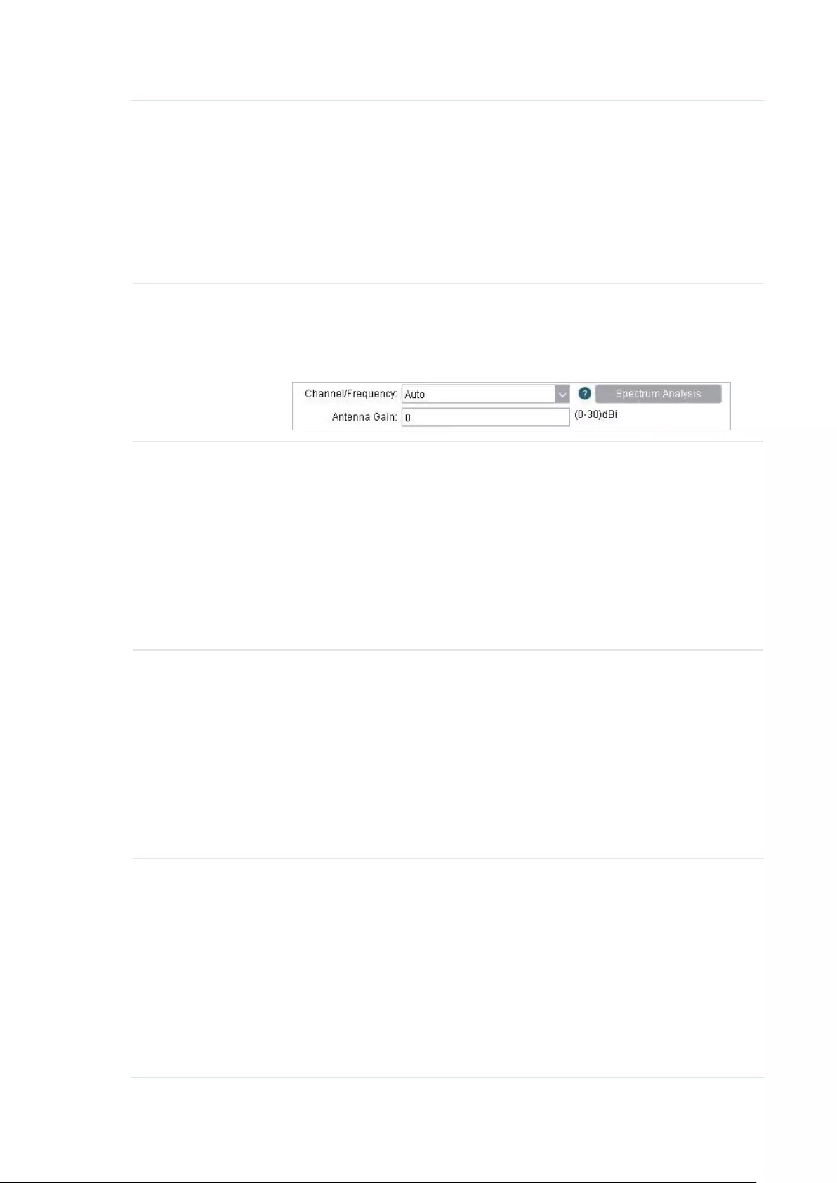
77
Channel/
Frequency
Select appropriate channel used by this device to improve wireless
performance. 1/2412MHz refers to Channel 1 and the frequency is
2412MHz. This setting is only available in Access Point mode and AP Router
mode.
CPE210/CPE220/WBS210 is a device with a frequency of 2.4GHz and
CPE610/CPE510/CPE520/WBS510 has a frequency of 5GHz. We highly
recommend that you use the
Spectrum Analysis
tool to select a proper
channel.
Antenna Gain Antenna Gain is only available in WBS products. Enter the antenna gain
value according to the antennas and the value ranges from 0 to 30dBi. It
can work together with the transmit power to improve the transmit signal
quality.
Transmit Power Specify the transmit power of the device. You can use the slider or manually
enter the transmit power value. For WBS210 and WBS510, the maximum
transmit power varies according to the antenna gain value.
Note:
In most scenarios, it is unnecessary to select the maximum transmit power.
Selecting larger transmit power than your need may cause interference
to neighborhood. Also it consumes more power and will reduce longevity
of the device. Select appropriate transmit power to achieve the best
performance. You can use the
Speed Test
tool to find the best performance
MAXtream Enable or disable the MAXtream function. This function is only available
in Access Point mode and AP Router mode. MAXtream is a TP-Link
proprietary technology. It is based on TDMA (Time Division Multiple Access)
so that data streams are transmitted in their own time slots. MAXtream aims
to maximize throughput and minimize latency. “Hidden nodes” problem can
also be eliminated with MAXtream enabled.
Note:
MAXtream Technology is only compatible with Pharos series products.
Working with products from other manufacturer will cause network fault.
MAXtream
Station Mode
MAXtream Station Mode is available in Client mode, Bridge mode and AP
Client Router mode with the wireless AP settings disabled.
Auto Adjust: The device will choose the MAXtream station mode
automatically.
Latency First: Set the MAXtream station mode as Latency First and the time
sensitive stream such as VoIP will take precedence in MAXtream system.
Throughput First: Set the MAXtream station mode as Throughput First
and the stream that needs high throughput such as online games will take
precedence in MAXtream system.
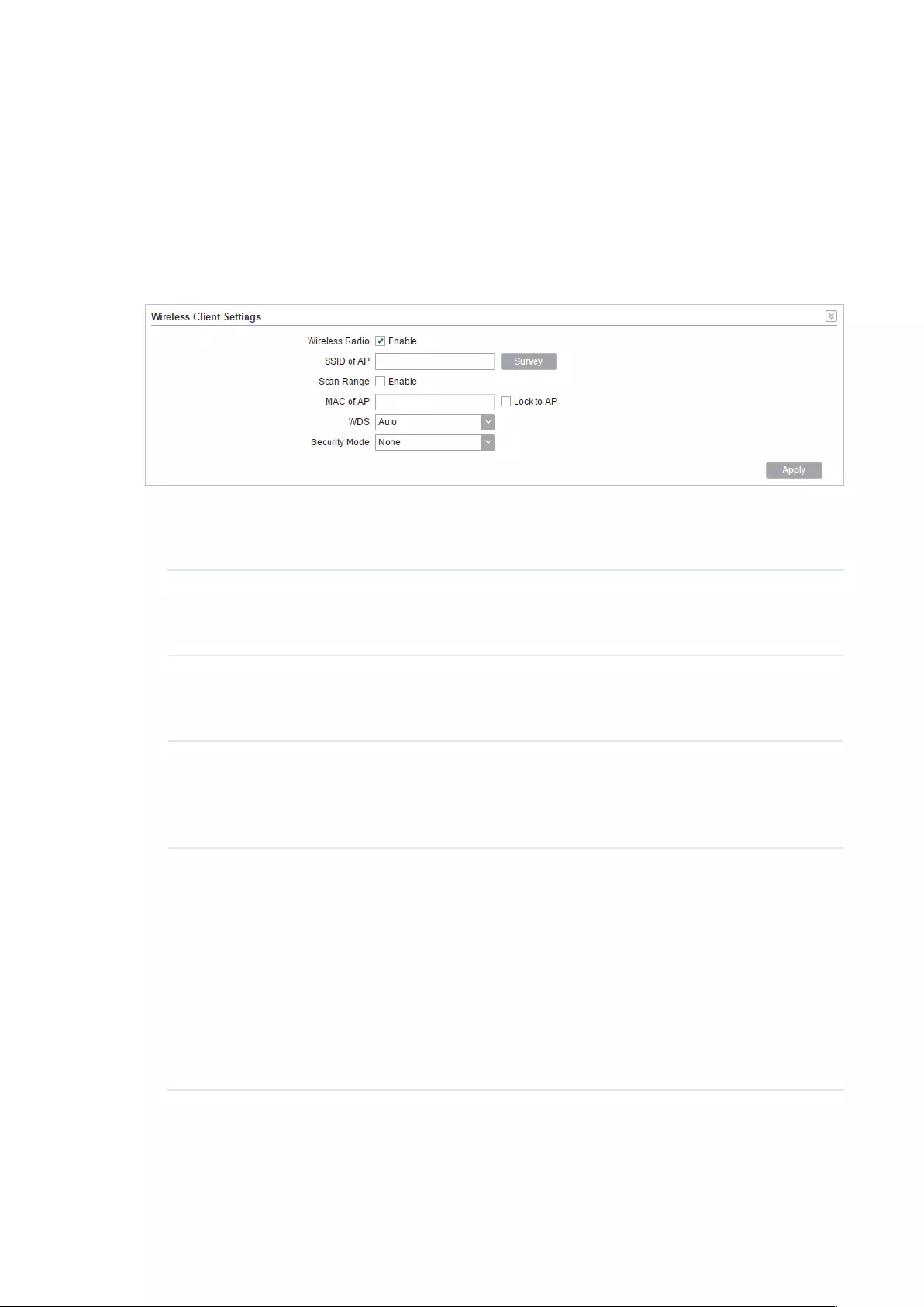
78
5.2 Configure Wireless Client Parameters
Note:
Wireless Client Settings submenu is only available in Client, Repeater, Bridge and AP client Router
(WISP client) mode.
In this section, you can configure wireless client parameters used for the connection with
the root AP.
1. Go to the Wireless Page. In the Wireless Client Settings section, configure the
following parameters.
SSID of AP Specify the SSID of the root AP. You can enter the SSID of the specific
AP manually, or you can directly survey all the APs around by clicking
Survey
and select one.
Scan Range Enable or disable the Scan Range. With the Scan Range enabled, you
need to specify the frequency range and the device will survey SSIDs in
the coeersponding range.
MAC of AP Displays the MAC address of the root AP. It’s possible that two or more
networks use the same SSID in the AP list. Enable Lock to AP to select
SSID and AP simultaneously, which can make the device connect to the
specific AP you had connected before the next time.
WDS Displays the status of the WDS (Wireless distribution System) function.
WDS is a communication system among multiple wireless networks . It is
established between APs through wireless connection. WDS is used to
during the connection between the device and the root AP.
Enable: Forward data frames to use four address fields.
Disable: Forward data frames to use three address fields.
Auto: The device automatically negotiates the wireless data frame
structure (three or four address fields) with the root AP. The selection of
Auto is recommended.
2. Specify the security mode. Make sure the Security mode and the related parameters
are the same as the upstream wireless network’s.

79
None
Select this option if the root AP has no encryption. When connecting to the root AP, it’s
no need to enter a password to access the wireless network.
WEP
WEP (Wired Equivalent Privacy) is a traditional encryption method. It has been proved
that WEP has security flaws and can easily be cracked, so WEP is rarely used in normal
wireless network. Select this option if the security mode of the root AP is WEP.
Note:
WEP is not supported in 802.11n mode or 802.11ac mode. If WEP is applied in 802.11n, 802.11
ac or 802.11n/ac mixed mode, the clients may not be able to access the wireless network. If
WEP is applied in 802.11b/g/n mode (2.4GHz) or 802.11a/n (5GHz), the device may work at a low
transmission rate.
Auth Type Select the authentication type for WEP.
Auto: The device can select Open System or Shared Key automatically
according to the wireless network of the root AP.
Open System: The device can pass the authentication and associate
with the root wireless network without password. However, correct
password is necessary for data transmission.
Shared Key: The device needs the correct password to pass the
authentication, otherwise the device cannot associate with the root
wireless network or transmit data.
Key Format Select ASCII or Hex as the WEP key format.
ASCII: With this format selected, the WEP key can be any combination of
keyboard characters of the specified length.
Hex: With this format selected, the WEP key can be any combination of
hexadecimal digits (0-9, a-f, A-F) with the specified length.
Key Selected Select one key to specify. You can configure four keys at most.

80
WEP Key Enter the WEP keys. The length and valid characters are determined by
the key format and key type.
Key Type Select the WEP key length for encryption.
64Bit: Enter 10 hexadecimal digits or 5 ASCII characters.
128Bit: Enter 26 hexadecimal digits or 13 ASCII characters.
152Bit: Enter 32 hexadecimal digits or 16 ASCII characters.
WPA
WPA (Wi-Fi Protected Access) is a safer encryption method compared with WEP
and WAP-PSK. It requires a RADIUS server to authenticate the clients via 802.1X and
EAP (Extensible Authentication Protocol). WPA can generate different passwords
for different clients, which ensures higher network security. But it also costs more to
maintain the network, so it is more suitable for business networks.
Version Select the version of WPA.
Auto: The device will automatically choose the version used by the root
AP.
WPA/WPA2: They’re two versions of WPA security mode. WPA2 is an
update of WPA. Compared with WPA, WPA2 introduces AES algorithm
and CCMP encryption. Theoretically, WPA2 is securer than WPA.
Encryption Select the Encryption type.
Auto: The default setting is Auto and the device will select TKIP or AES
automatically according to the wireless network of root AP.
TKIP: Temporal Key Integrity Protocol. TKIP is not supported in 802.11n
mode, 802.11ac mode or 802.11n/ac mixed mode. If TKIP is applied
in 802.11n, 802.11 ac or 802.11n/ac mixed mode, the device may not
be able to access the root wireless network. If TKIP is applied in 11b/
g/n mode (2.4GHz) or 11a/n mode(5GHz), the device may work at a low
transmission rate.
AES: Advanced Encryption Standard. It is securer than TKIP.
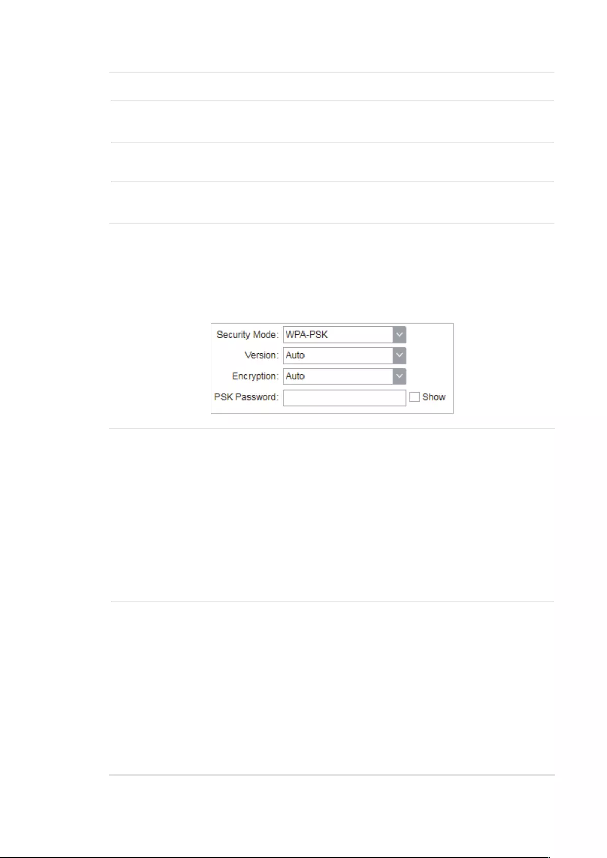
81
Authentication Select the type of the authentication.
Phase 2 Auth Select the type of Phase 2 Auth. The device only supports MSCHAPV2
currently.
WPA User
Name
Specify the WPA User Name used in the connection with the root AP.
WPA User
Password
Specify the WPA User Password used in the connection with the root
AP.
WPA-PSK
WPA-PSK (Wi-Fi Protected Access-PSK) is based on a pre-shared key. It is
characterized by high safety and simple settings, so it is mostly used by common
households and small businesses.
Version Select the version of WPA-PSK.
WPA-PSK/WPA2-PSK: They’re two versions of WPA-PSK security
mode. WPA2-PSK is an update of WPA-PSK. Compared with WPA,
Theoretically, WPA2 is securer than WPA.
Auto: The device will automatically choose the version used by the root
AP.
WPA/WPA2: They’re two versions of WPA-PSK security mode normally
called WPA-PSK/WPA2-PSK. WPA2-PSK is an update of WPA-PSK.
Compared with WPA-PSK, theoretically, WPA2-PSK is securer than
WPA-PSK.
Encryption Select the Encryption type.
Auto: The default setting is Auto and the device will select TKIP or AES
automatically according to the wireless network of root AP.
TKIP: Temporal Key Integrity Protocol. TKIP is not supported in 802.11n
mode, 802.11ac mode or 802.11n/ac mixed mode. If TKIP is applied
in 802.11n, 802.11 ac or 802.11n/ac mixed mode, the device may not
be able to access the root wireless network. If TKIP is applied in 11b/
g/n mode (2.4GHz) or 11a/n mode(5GHz), the device may work at a low
transmission rate.
AES: Advanced Encryption Standard. It is securer than TKIP.

82
PSK Password Specify the PSK password used in the connection with the root AP.
3. Click
Apply
, then click
Save
.
5.3 Configure Wireless AP Parameters
Note:
Wireless Client Settings submenu is only available in Access Point, Bridge, AP Router and AP client
Router (WISP client) mode.
In this section, you can configure wireless AP parameters used for the connection with the
clients.
1. Go to the Wireless Page. In the Wireless AP Settings section, specify the SSID.
Enable SSID
Broadcast
Enable or disable SSID broadcast. With this function enabled, the device
will broadcast the SSID periodically.
2. Specify the security mode used for the clients to access the wireless network.

83
None
Select None when you want an open network without wireless security. In this mode,
network data is not encrypted, but you can still authenticate clients by enabling the
RADIUS MAC Authentication function.
RADIUS MAC
Authentication
Enable or disable the Radius MAC authentication. With this feature
enabled, you can authenticate clients using their MAC addresses on
your RADIUS authentication server.
Remember to log into your RADIUS authentication server and create
authentication entries whose username and password are both the
access-enabled clients’ MAC address (for MAC address 11-22-33-AA-
BB-CC, create an authentication entry whose username and password
are both 112233aabbcc on the RADIUS server).
Authentication
Server IP
Enter the IP address of the RADIUS authentication server.
Authentication
Server Port
Enter the UDP port of the RADIUS authentication server. The most
commonly used port is the default, 1812, but this may vary depending
on the RADIUS authentication server you are using.
Authentication
Server Key
Enter the shared key used between this device and the authentication
server. The shared key is a case-sensitive text string used to validate
communication between this device and the RADIUS authentication
server.
Check the Show box to view the shared key characters.
Accounting
Server
Enable or disable Accounting Server. With this feature enabled, you can
keep accounts on users using a RADIUS accounting server.
Accounting
Server IP
Enter the IP address of the RADIUS accounting server.

84
Accounting
Server Port
Enter the UDP port of the RADIUS accounting server. The most
commonly used port is 1813, but this may vary depending on the
RADIUS accounting server you are using.
Accounting
Server Key
Enter the password used between this device and the RADIUS
accounting server. The shared key is a case-sensitive text string used to
validate communication between this device and the RADIUS accounting
server.
Check the Show box to view the shared key characters.
WEP
WEP (Wired Equivalent Privacy) is a traditional encryption method. It has been proved
that WEP has security flaws and can easily be cracked, so WEP cannot provide effective
protection for wireless networks. Since WPA-PSK and WPA-Enterprise are much safer
than WEP, we recommend that you choose WPA-PSK or WPA-Enterprise if your clients
also support them.
Note:
WEP is not supported in 802.11n mode or 802.11ac mode. If WEP is applied in 802.11n, 802.11
ac or 802.11n/ac mixed mode, the clients may not be able to access the wireless network. If
WEP is applied in 802.11b/g/n mode (2.4GHz) or 802.11a/n (5GHz), the device may work at a low
transmission rate.
Auth Type Select the authentication type for WEP.
Auto: The device can select Open System or Shared Key automatically
based on the wireless capability and request of the clients.
Open System: Clients can pass the authentication and associate with
the wireless network without password. However, correct password is
necessary for data transmission.
Shared Key: Clients have to input the correct password to pass the
authentication, otherwise the clients cannot associate with the wireless
network or transmit data.

85
Key Format Select ASCII or Hex as the WEP key format.
ASCII: With this format selected, the WEP key can be any combination of
keyboard characters of the specified length.
Hex: With this format selected, the WEP key can be any combination of
hexadecimal digits (0-9, a-f, A-F) with the specified length.
Key Selected Select one key to specify. You can configure four keys at most.
WEP Key Enter the WEP keys. The length and valid characters are determined by
the key format and key type.
Key Type Select the WEP key length for encryption.
64Bit: Enter 10 hexadecimal digits or 5 ASCII characters.
128Bit: Enter 26 hexadecimal digits or 13 ASCII characters.
152Bit: Enter 32 hexadecimal digits or 16 ASCII characters.
WPA
WPA (Wi-Fi Protected Access) is a safer encryption method compared with WEP
and WAP-PSK. It requires a RADIUS server to authenticate the clients via 802.1X and
EAP (Extensible Authentication Protocol). WPA can generate different passwords
for different clients, which ensures higher network security. But it also costs more to
maintain the network, so it is more suitable for business networks.

86
Version Select the version of WPA.
Auto: The device will automatically choose the version used by each
client device.
WPA/WPA2: They’re two versions of WPA security mode. WPA2 is an
update of WPA. Compared with WPA, WPA2 introduces AES algorithm
and CCMP encryption. Theoretically, WPA2 is securer than WPA.
Encryption Select the Encryption type.
Auto: The default setting is Auto and the device will select TKIP or AES
automatically based on the client device’s request.
TKIP: Temporal Key Integrity Protocol. TKIP is not supported in 802.11n
mode, 802.11ac mode or 802.11n/ac mixed mode. If TKIP is applied
in 802.11n, 802.11 ac or 802.11n/ac mixed mode, the device may not
be able to access the root wireless network. If TKIP is applied in 11b/
g/n mode (2.4GHz) or 11a/n mode(5GHz), the device may work at a low
transmission rate.
AES: Advanced Encryption Standard. It is securer than TKIP.
Authentication
Server IP
Enter the IP address of the Radius Authentication Server.
Authentication
Server Port
Enter the UDP port of the RADIUS authentication server. The most
commonly used port is 1812, but this may vary depending on the
RADIUS authentication server you are using.
Authentication
Server Key
Enter the shared key used between this device and the authentication
server. The shared key is a case-sensitive text string used to validate
communication between this device and the RADIUS authentication
server.
Check the Show box to view the shared key characters.
Group Key
Update Period
Specify an update period of the encryption key. The update period
instructs how often the device should change the encryption key. 0
means that the encryption key does not change at anytime.
Accounting
Server
Enable or disable Accounting Server. With this feature enabled, you can
keep accounts on users using a RADIUS accounting server.
Accounting
Server IP
Enter the IP address of the RADIUS accounting server.
Accounting
Server Port
Enter the UDP port of the RADIUS accounting server. The most
commonly used port is 1813, but this may vary depending on the
RADIUS accounting server you are using.
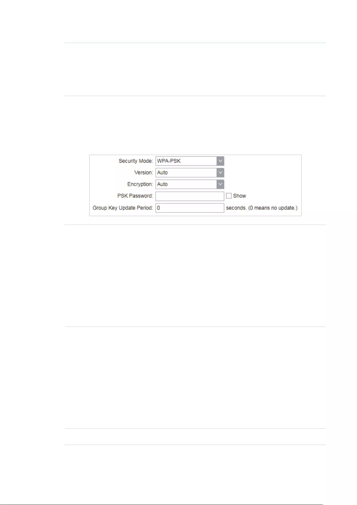
87
Accounting
Server Key
Enter the password used between this device and the RADIUS
accounting server. The shared key is a case-sensitive text string used to
validate communication between this device and the RADIUS accounting
server.
Check the Show box to view the shared key characters.
WPA-PSK
WPA-PSK (Wi-Fi Protected Access-PSK) is based on a pre-shared key. It is
characterized by high safety and simple settings, so it is mostly used by common
households and small businesses.
Version Select the version of WPA-PSK.
WPA-PSK/WPA2-PSK: They’re two versions of WPA-PSK security
mode. WPA2-PSK is an update of WPA-PSK. Compared with WPA,
Theoretically, WPA2 is securer than WPA.
Auto: The device will automatically choose the version used by the root
AP.
WPA/WPA2: They’re two versions of WPA-PSK security mode normally
called WPA-PSK/WPA2-PSK. WPA2-PSK is an update of WPA-PSK.
Compared with WPA-PSK, theoretically, WPA2-PSK is securer than
WPA-PSK.
Encryption Select the Encryption type.
Auto: The default setting is Auto and the device will select TKIP or AES
automatically according to the wireless network of root AP.
TKIP: Temporal Key Integrity Protocol. TKIP is not supported in 802.11n
mode, 802.11ac mode or 802.11n/ac mixed mode. If TKIP is applied
in 802.11n, 802.11 ac or 802.11n/ac mixed mode, the device may not
be able to access the root wireless network. If TKIP is applied in 11b/
g/n mode (2.4GHz) or 11a/n mode(5GHz), the device may work at a low
transmission rate.
AES: Advanced Encryption Standard. It is securer than TKIP.
PSK Password Specify the PSK password used in the connection with the clients.

88
Group Key
Update Period
Specify an update period of the encryption key. The update period
instructs how often the device should change the encryption key. 0
means that the encryption key does not change at anytime.
3. Click
Apply
, then click
Save
.
5.4 Configure Multi-SSID
Note:
Multi-SSID submenu is only available in Access Point mode.
The device can build up to four virtual wireless networks for users to access. When the
Multi-SSID function is enabled, the VLAN function is enabled at the same time. It can work
together with switches supporting 802.1 Q VLAN and supports maximum four VLANs. The
device adds different VLAN tag to the clients which connect to the corresponding wireless
network. The clients in different VLANs cannot directly communicate with each other.
The wired client can communicate with all the wireless clients despite the VLAN settings.
1. Go to the Wireless page. In the Multi-SSID section, Enable Multi-SSID. Click
Add
and
create a new wireless network.
SSID Specify the SSID of the wireless network.
VLAN Specify the VLAN to which the new wireless network belongs. The valid
value ranges from 1 to 4094.
SSID Broadcast Enable or disable SSID broadcast . With this feature enabled, the device
will broadcast the SSID.
AP Isolation Enable or disable AP Isolation. With this feature enabled, all the hosts
cannot communicate with each other.

89
2. Select the desired SSID and specify the Security.
SSID Select the desired SSID to specify the security settings.
Security Specify the security settings for the desired SSID. The device only
supports WPA-PSK.
Version Select the version of WPA-PSK.
WPA-PSK/WPA2-PSK: They’re two versions of WPA-PSK security
mode. WPA2-PSK is an update of WPA-PSK. Compared with WPA,
Theoretically, WPA2 is securer than WPA.
Auto: The device will automatically choose the version used by the root
AP.
WPA/WPA2: They’re two versions of WPA-PSK security mode normally
called WPA-PSK/WPA2-PSK. WPA2-PSK is an update of WPA-PSK.
Compared with WPA-PSK, theoretically, WPA2-PSK is securer than
WPA-PSK.
Encryption Select the Encryption type.
Auto: The default setting is Auto and the device will select TKIP or AES
automatically according to the wireless network of root AP.
TKIP: Temporal Key Integrity Protocol. TKIP is not supported in 802.11n
mode, 802.11ac mode or 802.11n/ac mixed mode. If TKIP is applied
in 802.11n, 802.11 ac or 802.11n/ac mixed mode, the device may not
be able to access the root wireless network. If TKIP is applied in 11b/
g/n mode (2.4GHz) or 11a/n mode(5GHz), the device may work at a low
transmission rate.
AES: Advanced Encryption Standard. It is securer than TKIP.
PSK Password Specify the PSK password used in the connection with the clients.
Group Key
Update Period
Specify an update period of the encryption key. The update period
instructs how often the device should change the encryption key. 0
means that the encryption key does not change at anytime.
3. Click
Apply
, then click
Save
.

90
5.5 Configure Wireless MAC Filtering
Wireless MAC Filtering function uses MAC addresses to determine whether one host can
access the wireless network or not. Thereby it can eectively control the user access in the
wireless network. This function is available in all modes except the client mode.
1. Go to the Wireless page. In the Wireless MAC Filtering section, enable this feature and
specify the filtering rule.
Wireless MAC
Filtering
Enable or disable the Wireless MAC Filtering function.
Filtering Rules Specify the filtering rules.
Allow the stations specified by any enabled entries in the list to access
the network: The stations listed in the table are allowed to access the
wireless network under the rules. While others are forbidden to access.
Deny the stations specified by any enabled entries in the list to access
the network: The stations listed in the table are forbidden to access the
wireless network under the rules. While others are allowed to access.
2. Click
Add
and specify the following parameters.
Enable Enable or disable the desired entry.
SSID Select te SSID to which the filtering rules apply. In AP mode, if Multi-SSID
is enabled, you should set different filtering rules for each SSID.
MAC Enter the MAC address of the wireless host that you need to filter.
Comment Enter the description information for the filtering rule
3. Click
Save
and click
Apply
. Then click
Save
.
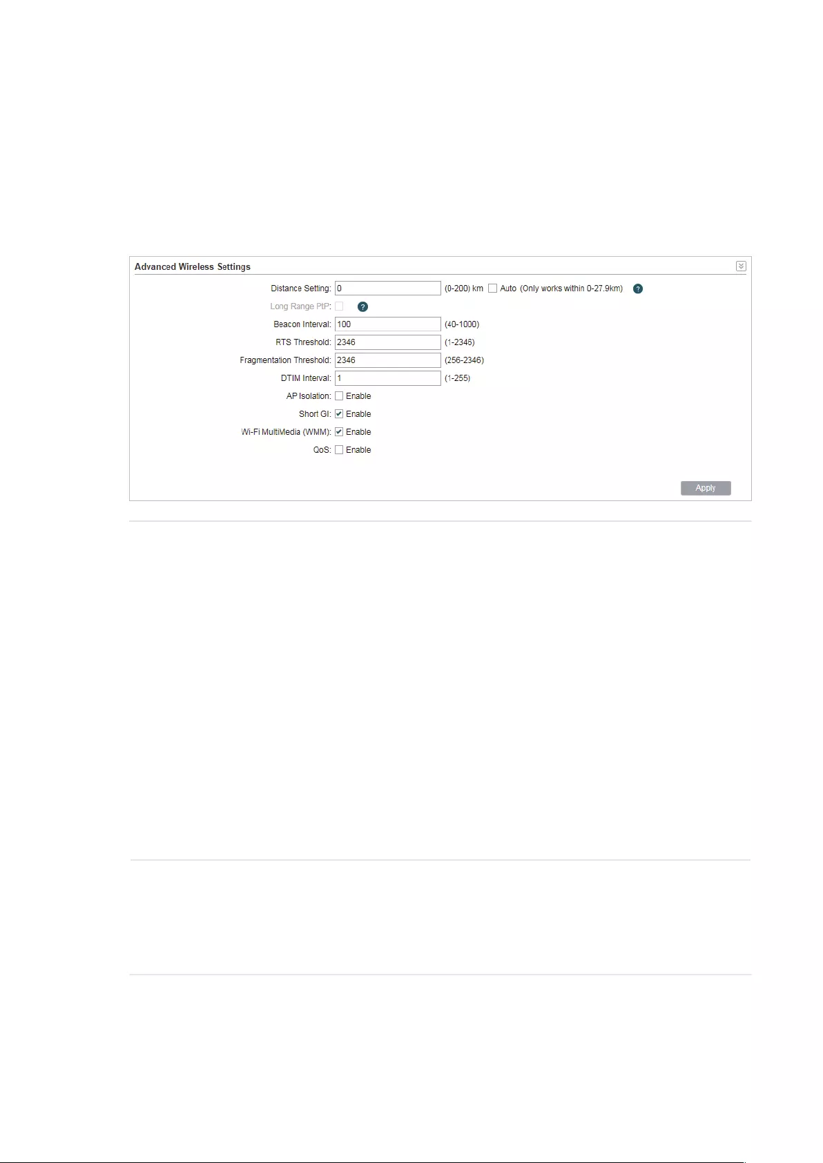
91
5.6 Configure Advanced Wireless Parameters
This section is used to specify the advanced wireless parameters, such as Beacon Interval,
RTS threshold and DIM Interval.
Go to the Wireless page. In the Advanced Wireless Settings section, specify the following
parameters and click
Apply
. Then click
Save
.
Distance
Setting
Specify the distance between AP and Station. If this device serves as a
client, the value is the distance between this device and the root AP. If this
device serves as an AP, the value is the distance between the farthest client
and this AP.
You can manually enter the value or enable the Auto option.
Manual: Enter the distance manually in the input box. The value is limited
to 0-200km, and we recommend you set the value to 110% of the real
distance.
Auto (Only works within 0-xx km): Check the Auto option, then the system
will dynamically detect the distance. This function is available only when
the distance is less than xx kilometers. The value xx varies according to the
channel width you set. CPE210 does not support this option.
The distance value will be converted to a corresponding ACK timeout value,
and the ACK timeout value will influence the throughput performance to a
large extent.
Beacon Interval Specify the beacon interval for the device. Beacons are transmitted
periodically by the device to announce the presence of a wireless network
for the clients. Beacon Interval value determines the time interval of the
beacons sent by the device. You can specify a value from 40 to 1,000. The
default value is 100.

92
RTS Threshold Specify the RTS threshold for the device.
RTS/CTS (Request to Send/Clear to Send) is used to improve the data
transmission efficiency of the network with hidden nodes, especially when
there are lots of large packets to be transmitted.
When the size of a data packet is larger than the RTS Threshold, the RTS/
CTS mechanism will be activated. With this mechanism activated, before
sending a data packet, the client will send an RTS packet to the device to
request data transmitting. And then the device will send CTS packet to
inform other clients to delay their data transmitting. In this way, packet
collisions can be avoided.
For a busy network with hidden nodes, a low threshold value will help
reduce interference and packet collisions. But for a not-so-busy network, a
too low threshold value will cause bandwidth wasting and reduce the data
throughput. The recommended and default value is 2346 bytes.
Fragmentation
Threshold
Specify the fragmentation threshold for packets.
The fragmentation function can limit the size of packets transmitted over
the network. If the size of a packet exceeds the Fragmentation Threshold,
the fragmentation function is activated and the packet will be fragmented
into several packets.
Fragmentation helps improve network performance if properly configured.
However, a too low fragmentation threshold may result in poor wireless
performance caused by the extra work of dividing up and reassembling of
frames and increased message traffic. The recommended and default value
is 2346 bytes.
DTM Interval Specify the DTM (Delivery Traffic Indication Message) Interval for the
device.
The DTIM is contained in some Beacon frames. It indicates whether the
device has buffered data for client devices. The DTIM Period indicates how
often the clients served by this device should check for buffered data still
on the device awaiting pickup.
You can specify the value between 1-255 Beacon Intervals. The default
value is 1, indicating that clients check for buffered data at every beacon.
An excessive DTIM interval may reduce the performance of multicast
applications, so we recommend you keep the default value.
AP Isolation Enable or disable AP Isolation. With this feature enabled, the clients can not
communicate with each other directly.
Note:
AP Isolation is not available in Client mode.

93
Short GI Enable or disable Short GI.
Propagation delays often occurs in data transmission process and
influence the capability of the wireless network. It can result from multiple
factors, such as multipath effect. GI (Guard Interval) is intended to solve the
problem based on delays, and Short GI is used to improve the throughput of
the wireless network based on the GI in the environment with small delays.
When the delays are small. When Short GI is enabled, the guard interval will
be set as 400ns and this function will boost the performance about 11%.
In the with serious multipath time delay. Short GI function will reduce the
throughput instead of improving it.
Wi-Fi
Multimedia
(WMM)
Enable or disable WMM. With WMM enabled, the system will prioritize traffic
according to the data type when forwarding data. Time-dependent traffic,
such as video or audio packets, gets a higher priority than normal traffic.
We recommend you enable this function when you are running the video or
audio application.
QoS Enable or disable QoS. The QoS function improves the transmission
performance of video or audio traffic by optimizing the scheduling policy
between the AP and the clients.

94
6 Manage the Device
The device provides powerful functions of management and maintenance. This chapter
introduces how to manage the device, including:
6.1 Manage System Logs
6.2 Specify the Miscellaneous Parameters
6.3 Configure Ping Watch Dog
6.4 Configure Dynamic DNS
6.5 Configure Web Server
6.6 Configure SNMP Agent
6.7 Configure SSH Server
6.8 Configure RSSI LED Thresholds
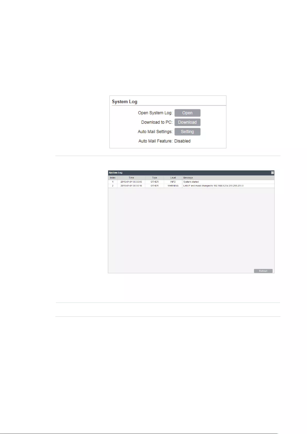
95
6.1 Manage System Logs
System logs record the events and activities while the device is running. If a failure happens on
the router, System logs can help to diagnose the issue.
1. Go to the Management page. In the System Log section, you can perform the following
operations.
Open System
Log
Click the
Open
button to view the system log.
This page displays detailed system logs that can be sorted on columns
by ascending or descending order. Columns can be chosen from Time,
Type, Level, and Message.
Download to PC Click the
Download
button to download the system logs to your PC.

96
2. Click the
Setting
button to specify the Auto Mail Settings.
From Enter the sender’s E-mail address.
To Enter the receiver’s E-mail address.
SMTP Server Enter the IP address of the sender’s SMTP server.
Authentication Enable or disable the authentication function. If the sender’s mailbox is
configured. You can check the box to enable mail server authentication.
Enter the sender’s username and password.
Auto Mail
Feature
Enable or disable Auto Mail Feature. With this feature enabled, you can
specify the way for the device to send the system log.
6.2 Specify the Miscellaneous Parameters
This section is used to specify miscellaneous parameters.
1. Go to the Management Page. In the Miscellaneous section, configure the following
features and click
Apply
.

97
Discovery Enable or disable Discovery. With this feature enabled, TP-Link Pharos
Control software can discover the device. Pharos Control is a network
management software developed independently by TP-Link and it
currently supports Pharos series products. It can centralize monitoring
and managing network devices in the network platform
CDP Enable or disable CDP. With this function enabled, this device can share
its information with the neighboring devices that support CDP (Cisco
Discovery Protocol, a device discovery protocol developed by Cisco).
2. Click
Save
.
6.3 Configure Ping Watch Dog
Ping Watch Dog sets the device to continuously ping a user-dened IP address (it can be the
internet gateway, for example) to check the network connectivity. If there is a connection
failure then the device will automatically reboot.
Ping Watch Dog is dedicated to continuously monitoring the connectivity to a specific host
using the Ping tool. The Ping tool sends ICMP echo request packets to the target host and
listens for ICMP echo response. If the defined number of replies is not received, the tool
reboots the device.
1. Go to the Management Page. In the Ping Watch Dog section, Enable this feature and
configure the following features. Click
Apply
.
Ping Watch Dog Enable or disable Ping Watch Dog.
IP Address To
Ping
Specify the IP address of the target host to which the device will send
ping packets.
Ping Interval Enter the time interval between two ping packets. The default value is
300 seconds.

98
Startup Delay Enter the initial time delay from device startup to the first ICMP echo
requests sent by Ping Watch Dog. The default value is 300 seconds.
The Startup Delay value should be at least 60 seconds taking the
device‘s initialization time in account.
Fail Count To
Reboot
Enter the fail count of ICMP echo request. If the device sends the
specified count of ICMP echo requests to the host and none of the
corresponding ICMP echo response packets is received, Ping Watch
Dog will reboot the device. The default value is 3.
2. Click
Save
.
6.4 Configure Dynamic DNS
Note:
The Dynamic DNS function is only available in AP router and AP Client router (WISP Client) mode.
The main function of Dynamic DNS (DDNS) is mapping the xed domain name to dynamic IP
address.
When a device connects to the internet through PPPoE or Dynamic IP, the WAN IP address
it gets is not fixed, which is inconvenient for the internet users to access the servers in the
local area network through IP address. With Dynamic DNS function enabled, users can access
servers using a xed domain name.
The DDNS server will establish a mapping table about the dynamic IP address and the fixed
domain name. When the WAN IP address of the device changes, it will make an update request
to the specified DDNS server, and then the DDNS server will update the mapping relation
between the IP address and the domain name. Therefore, whenever the WAN IP address
changes, users on the internet can still access the servers in the local area network using a
xed, easy-to-remember domain name.
The DDNS function that serves as the client of DDNS service must work with DDNS server.
Please register an account to DDNS service provider (NO-IP, Dyndns or Comexe) rst.

99
1. Go to the Management page. In the Dynamic DNS section, configure the following
parameters and click
Login
.
Service
Provider
Select the service provider.
Dynamic DNS Enable or disable the Dynamic DNS feature.
User Name Enter the user name of your DDNS account.
Password Enter the password of your DDNS account.
Domain Name Specify the domain name that you registered with your DDNS service
provider.
Connection
Status
Displays the connection status of the DDNS service.
2. Click
Apply
, then click
Save
.
6.5 Configure Web Server
This function is used to congure the related parameters of Web server. Users can log in to the
web management page to manage this device remotely over the internet through Web Server.

100
1. Go to the Management page. In the Web Server section, configure the following
parameters and click
Apply
.
Secure
Connection
(HTTPS)
Enable or disable the HTTPS feature. HTTPS function is based on the
SSL or TLS protocol working in transport layer. It supports a security
access via a web browser.
Secure Server
Port
Specify the server port number used in HTTPS. The default value is 443.
Server Port Specify the server port number used in HTTP. The default value is 80.
Remote Login
IP Address
Specify the IP address of the remote host. With this configured, the
remote device can access the management interface remotely.
Session
Timeout
Specify the session timeout time. The system will automatically release
the connection when the time is up.
MAC
Authentication
Enable or disable MAC Authentication. When it is enabled, you can
specify up to four MAC address for authentication.
With this function enabled, only the device whose MAC address is in the
MAC list can access the management interface to configure the device.
You can click
Add PC’s MAC
to quickly add your PC’s MAC address to
the MAC list.
2. Click
Apply
, then click
Save
.
6.6 Configure SNMP Agent
You can get the trac information and transmit condition by using the SNMP Agent function.

101
Simple Network Management Protocol (SNMP) is an application layer protocol that facilitates
the exchange of management information between network devices. Main functions of SNMP
include monitoring network performance, detecting and analyzing network error, conguring
network devices, and so on. When the network working normally, SNMP can monitor the
statistics, configuration. When networks have troubles, SNMP can detect and restore these
troubles.
Configure the device as SNMP Agent, and it can receive and process the management
message from the network management system.
1. Go to the Management page. In the SNMP Agent section, configure the following
parameters and click
Apply
.
SNMP Agent Enable or disable the SNMP Agent function.
SysContaact Enter the textual identification of the contact person for this the device,
for example, contact or e-mail address.
SysName Enter a name for the device.
Syslocation Enter the location of the device. For example, the name can be
composed of the building, floor number, and room location.
Get Community Specify the community that has read-only access to the device’s SNMP
information.
Get Source Enter the IP address that can serve as Get Community to read the SNMP
information of this device.
Set Community Specify the community who has the read and write right of the device’s
SNMP information.
Set Source Enter the IP address that can serve as Set Community to read and write
the SNMP information of this device.
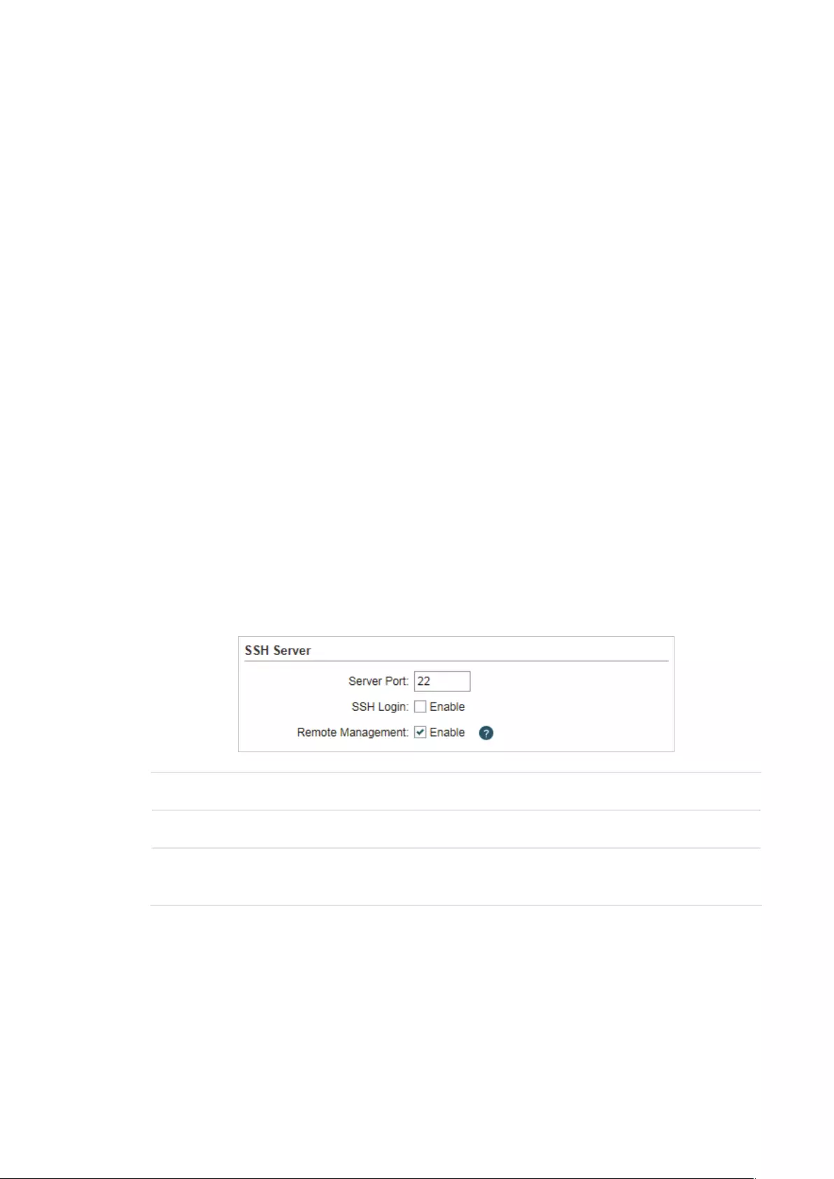
102
2. Click
Apply
, then click
Save
.
Note:
Defining community can allow management systems in the same community to communicate with
the SNMP Agent. The community name can be seen as the shared password of the network hosts
group. Thus, for the safety, we suggest modifying the default community name before enabling
the SNMP Agent service. If the field of community is blank, the SNMP Agent will not respond to any
community name.
6.7 Configure SSH Server
The SSH Server function is used for the users to log in and manage the device through SSH
connection on the SSH client software.
SSH (Secure Shell) is a security protocol established on application and transport layers. SSH-
encrypted-connection is similar to a telnet connection, but essentially the old telnet remote
management method is not safe, because the password and data transmitted with plain-text
can be easily intercepted. SSH can provide information security and powerful authentication
when you log in this device remotely through an insecure network environment. It can encrypt
all the transmission data and prevent the information in remote management from being
leaked.
1. Go to the Management page. In the SSH Server section, configure the following
parameters and click
Apply
.
Server Port Enter the TCP/IP port of the SSH Server. The default port is 22.
SSH Login Enable or disable SSH function.
Remote
Management
Enable or disable Remote Management. With this function enabled, TP-
Link Pharos Control software can manage the device remotely.
2. Click
Save
.
6.8 Configure RSSI LED Thresholds
You can configure the LEDs on the device to light up when received signal levels reach the
values defined in the following fields. This function can help a technician to easily deploy a

103
Pharos series product without logging into the device (for example, for antenna alignment
operation).
Note:
CPE610 doesn’t support this feature.
1. Go to the Management page. In the RSSI LED Thresholds section, configure the
following parameters and click
Apply
.
LED1/LED2/
LED3/LED4
Displays the LED number.
Thresholds Specify the threshold for the desired LED. The specified LED will light up
if the signal strength reaches the values in the field. The default values
are set according to the verified optimum values. We recommend you
keep it by default.
The default LED threshold values may vary among different product
models in terms of radio features.
2. Click
Apply
, then click
Save
.

104
7 Congure the System
This chapter introduces how to configure the system of the device, including:
7.1 Configure Device Information
7.2 Configure Location Information
7.3 Configure User Account
7.4 Configure Time Settings
7.5 Update Firmware
7.6 Configure Other Settings
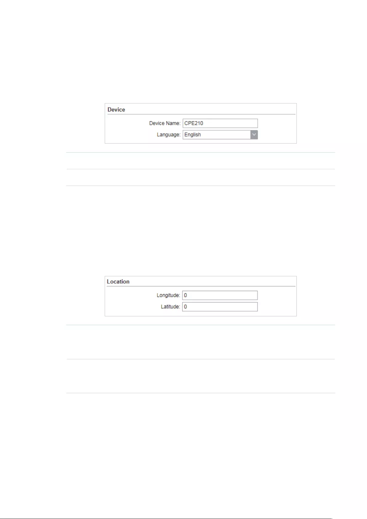
105
7.1 Configure Device Information
In this section, you can congure the device name and the system language.
1. Go to the System page. In the Device section, configure the following parameters and
click
Apply
.
Device Name Specify the device name.
Language Specify the system language used in the management interface.
2. Click
Save
.
7.2 Configure Location Information
In this section, you can congure the location for the device.
1. Go to the System page. In the Location section, configure the following parameters and
click
Apply
.
Longitude Enter the longitude of the device’s location in decimal degree. The
positive number indicates the east longitude while the negative number
indicates the west longitude.
Latitude Enter the latitude of the device’s location in decimal degree. The positive
number indicates the north latitude while the negative number indicates
the south latitude.
2. Click
Save
.
7.3 Configure User Account
This section is used to congure user account.
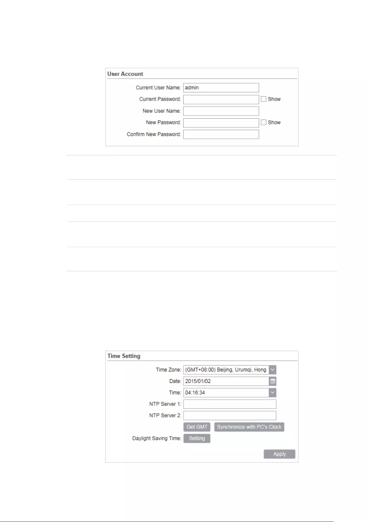
106
1. Go to the System page. In the User Account section, configure the following
parameters and click
Apply
.
Current User
Name
Displays the current user name.
Current
Password
Enter the current password for the user account. Check the
Show
box to
display what you’ve entered.
New User Name Enter a new user name for the user account.
New Password Enter a new password for the user account. Check the
Show
box to
display what you’ve entered.
Confirm New
Password
Confirm the new password.
2. Click
Save
.
7.4 Configure Time Settings
In this section, you can congure the system time and the daylight saving time.
1. Go to the System page. In the Time Settings section, configure the system time.

107
Manually
Configure the System time manually.
Time Zone Select your local time zone.
Date Click the calendar button to choose the date or enter the date in the
format: YYYY/MM/DD.
Time Select the time from the drop-down list or enter the time in the format
HH:MM:SS.
Automatically
• Specify the NTP Server, then click the
Get GMT
button to get the system time from
the NTP server
NTP Server 1 Specify the primary NTP server used to get time automatically.
NTP Server 2 Specify the alternate NTP server used to get time automatically.
• Click
Synchronize with PC’s Clock
to synchronize the system time with the PC’s time.
2. Click the
Setting
button to specify the daylight saving time.
Predefined mode
Select Predefined mode and select the predefined daylight saving time schedule for
the device.
USA The daylight saving time of USA is from Second Sunday in March, 02:00
to First Sunday in November, 02:00.

108
European The daylight saving time of European is from Last Sunday in March,
01:00 to Last Sunday in October, 01:00.
Australia The daylight saving time of Australia is from First Sunday in October,
02:00 to First Sunday in April, 03:00.
New Zealand The daylight saving time of New Zealand is from Last Sunday in
September, 02:00 to First Sunday in April, 03:00.
Recurring mode
Select Recurring mode and configure the related parameters for the device. This
configuration will be used every year.
Offset Specify the time to set the clock forward by.
Start Time Specify the start time of Daylight Saving Time.
End Time Specify the end time of Daylight Saving Time.
Recurring mode
Select Date mode and configure the related parameters for the device. This
configuration will be used only one time.
Offset Specify the time to set the clock forward by.
Start Time Specify the start time of Daylight Saving Time.
End Time Specify the end time of Daylight Saving Time.
3. Click
Apply
, then click
Save
.
7.5 Update Firmware
This section is used to view the current rmware and update the rmware of the device.
Go to the System page. In the Firmware Update section, click
Browser
to select a firmware
file then click
Upload
.
Firmware
Version
Displays the current firmware version of the device.

109
Note:
· We recommend that you back up current system configuration before updating the firmware.
· Please select the proper software version that matches your hardware to upgrade. You can visit
TP-Link website to download the latest firmware.
· To avoid damage, please do not power off the device while upgrading.
· After upgrading, the device will reboot automatically.
7.6 Configure Other Settings
This section is used to back up or upload the conguration le, reset the device and reboot the
device.
Go to the System Page. In the Conguration section, you can perform the following operations.
Backup
Configuration
Click
Backup
to back up the current configuration to your PC.
Upload
Configuration
Click
Browser
to select the desired configuration file in your PC. Then click
Upload
to upload the configuration file to your device. We recommend that
you back up your current system configuration before uploading the new
configuration.
Reset to
Factory
Defaults
Click
Reset
to restore the device to its factory defaults. It’s recommended
to back up your current system configuration before restoring the device to
its defaults.
Reboot Device Click
Reboot
to reboot the device. Note that any changes that have not
been saved will be lost.
Note:
· After backup, the device will reboot automatically.
· To avoid damage, DO NOT turn off the device while uploading.

110
8 Use the System Tools
This chapter introduces how to configure the system tools:
8.1 Configure Ping
8.2 Configure Traceroute
8.3 Test Speed
8.4 Survey
8.5 Analyze Spectrum
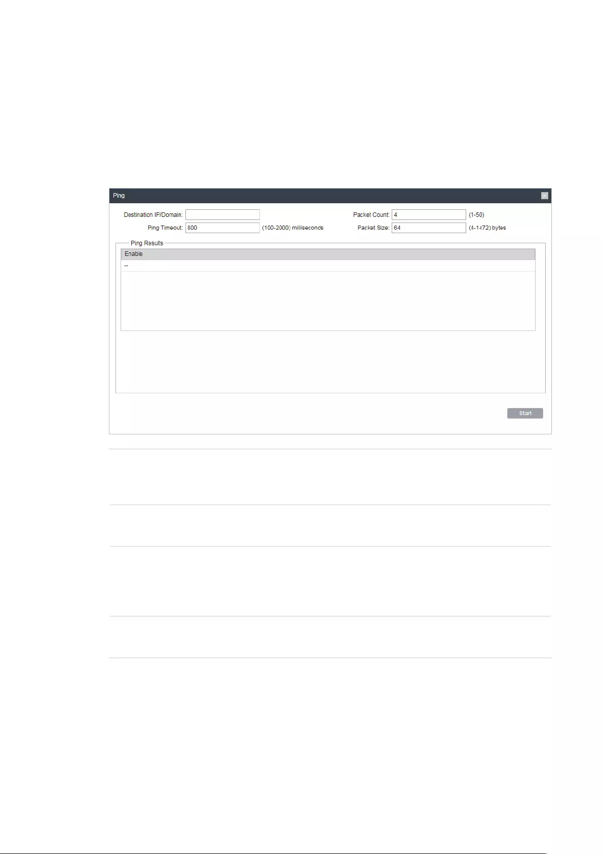
111
8.1 Configure Ping
Ping test function is used to test the connectivity and reachability between the device and
the target host so as to locate the network malfunctions.
1. Click
Ping
from the drop-down list on the upper-right corner and specify the following
parameters.
Destination IP/
Domain
Enter the IP address of the destination node for Ping test. The device will
send Ping packets to test the network connectivity and reachability of
the host and the results will be displayed in the Ping Result.
Packet Count Enter the number of packets to be sent during the testing. It can be 1 to
50 and the default is 4.
Ping Timeout Enter a time value to wait for a response. If the device doesn’t receive
ant response during the timeout time, the connection will be considered
to be failed. It can be 100-2000 milliseconds. The default value is 800
milliseconds.
Packet Size Enter the number of data bytes to be sent. It can be 4-1472 bytes and
the default is 64.
2. Click
Start
.
8.2 Configure Traceroute
Tracertroute function is used to tracks the route packets taken from source on their way
to a given target host. When malfunctions occur in the network, you can troubleshooting
with traceroute utility.

112
1. Click
Traceroute
from the drop-down list on the upper-right corner and specify the
following parameters.
Destination IP/
Domain
Enter the IP address of the destination node for Traceroute test. The
device will send Traceroute packets to test the network connectivity
and reachability of the host and the results will be displayed in the
Traceroute.
Traceroute Max
TTL
Specify the traceroute max TTL (Time To Live) during the traceroute
process. It is the maximum number of the route hops the test packets
can pass through.
2. Click
Start
.
8.3 Test Speed
Speed Test tool is used for testing the throughput between two Pharos products in the
same network. The test requires one of the two devices to be set as a server and the other
as a client. The client launches the test request to the server and the server respond to it.
The test result will display on the page of the client.

113
1. Click
Speed Test
from the drop-down list on the upper-right corner and specify the
following parameters.
Speed Test Displays the data streams that the device is transmitting (TX), receiving
(RX) and both of them (Total).
Server Select Server and the device will passively accept the test request from
the clients in the speed test process.
Client Select Client and the device will launch the test request to the server in
speed test process.
Server IP Specify the server IP for speed test.
Direction Select the direction of the speed test including unidirectional (RX),
unidirectional (TX) and bidirectional.
Testing Displays the process of the test.
2. Click
Start
.
8.4 Survey
The survey tool is used to survey the wireless network around the device.

114
Click
Survey
from the drop-down list on the upper-right corner and the following page will
appear.
BSSID Displays the BSSID of other APs surveyed by this device.
SSID Displays the SSID of other APs surveyed by this device.
MAXtream Displays the MAXtream capability of other APs surveyed by this device.
Device Name Displays the names of other APs surveyed by this device.
SNR(dB) Displays the Signal Noise Ratio (Unit: dB) of other APs surveyed by this
device.
Signal/Noise
(dBm)
Displays the signal and noise value (Unit: dBm) of other APs surveyed by
this device.
Channel Displays the channels of other APs surveyed by this device.
Security Displays the security mode of APs surveyed by this device.
AP Count Displays the number of other APs surveyed by this device.
Refresh Click
Refresh
to refresh this page.

115
8.5 Analyze Spectrum
Spectrum Analysis can help you to choose the proper channel/frequency. Through the
spectrum analysis you can learn the distribution of the radio noise and intelligently select
the channel/frequency in low noise.
1. Click
Spectrum Analysis
from the drop-down list on the upper-right corner and click
Yes
on the pop-up window.
2. Click
Start
. Observe the curves for a period of time, and then click
Stop
. The relatively
low and continuous part of the average curve indicates less radio noise. Here we take
the figure below as an example.
Note:
· Only CPE610/CPE510/CPE520/WBS510 has the select box of Frequency Range at the upper—
left corner. Select the required range and then click
Start
.
3. When choosing Channel/Frequency, try to avoid the spectrum with large radio noise.

116
COPYRIGHT & TRADEMARKS
Specifications are subject to change without notice. is a registered trademark
of TP-Link Technologies Co., Ltd. Other brands and product names are trademarks or
registered trademarks of their respective holders.
No part of the specifications may be reproduced in any form or by any means or used to
make any derivative such as translation, transformation, or adaptation without permission
from TP-Link Technologies Co., Ltd. Copyright © 2018 TP-Link Technologies Co., Ltd.. All
rights reserved.

117

Installation Guide Outdoor CPE
Setup with videos
Scan the QR code or visit https://www.tp-link.com/support/setup-video/
Contents
Overview 01
Hardware Connection 04 Site Consideration 04 Connection and Installation 06 Lightning & ESD Protection 08
Software Configuration 10 Logging in to the PharOS 10 Typical Application Configuration 12
Antenna Alignment 14
Specifications 15
FAQ 16
01
Overview TP-Link’s Pharos series outdoor CPEs are dedicated to outdoor wireless network solutions. This guide is applicable to products including CPE205, CPE210, CPE220, and CPE510.
Package Contents
Pharos CPE Passive PoE Adapter
Pole Mounting Straps
Mounting Bracket Plastic Wall Anchors (Qty.2) Self-tapping Screws (Qty.2)
Installation Guide
Power Cord
LED Explanation The following picture takes CPE220 as an example.
PO W
ER LAN0
LAN1
AP/AP Router Mode:
All four LEDs remain solid.
Client/Bridge/Repeater/AP Client Router Mode:
That the more LEDs lit will indicate better wireless signal strength.
Flashing: A device is connected to this port, and is active.
On: The CPE is powered on.
On: A device is connected to this port, but there is no activity.
02
Panel Layout Pharos CPE205/CPE220:
Shielded Ethernet Port LAN0 (Passive PoE IN)
RESETShielded Ethernet Port LAN1
Grounding Terminal
Pharos CPE210/CPE510:
Shielded Ethernet Port LAN (Passive PoE IN)
Grounding Terminal
RESET
03
Passive PoE Adapter:
Remote Reset Press and hold for about 8 seconds until CPEs LEDs of wireless signal strength and LAN flash.
Power LED The Power LED is on when the passive PoE adapter is working normally.
04
Hardware Connection
1. Site Consideration
Mounting Height Ensure a clear line of sight between the wireless devices for an optimum performance. An elevated location is recommended as obstacles like trees, buildings and large steel structures will weaken the wireless signal. See ‘Q2’ in ‘FAQ’ for details about how to calculate the minimum mounting height of the devices.
Line of Sight
Side View
05
Orientation Install the CPE devices with the front facing the intended signal receiving devices. You can orient the devices with the assistance of Google Maps, GPS and some landmarks according to the horizontal beamwidth listed below.
Models CPE210 CPE205/CPE220 CPE510 Horizontal Beamwidth 65 60 45
A
shenzhen
B
Line of S ight
Horiz ontal
Beamwidth
06
2. Connection and Installation Connect and mount the CPE and power adapter as shown below. The following introduction takes CPE220 as an example.
Connecting CPE and Power Adapter Connect the CPE and power adapter as shown in the figure below.
Ethernet cable length up to 60m
You should prepare an adequate Ethernet cable to connect the CPE and the passive PoE adapter. Shielded CAT5e (or above) cable with ground wire is recommended (refer to the next section).
Connect to a computer, router or switch. (Depending on your intended usage and/or network topology.)
Slide to replace the cover of the CPE when all connections are finished.
LAN0 PoE LAN
07
Mounting CPE At the selected site, approximately align the CPE to the direction that you have oriented.
Mounting Power Adapter (Optional) Follow the steps below to mount the power adapter:
To ensure the passive PoE adapter is attached most securely, it is recommended to install the adapter with the Ethernet port facing upward.
1. Drill two holes on the wall and insert the plastic wall anchors into the holes. Secure the mounting bracket to the wall. Make sure the shoulders at the corners of the mounting bracket are on the outside and pointing upward.
2. Attach the passive PoE adapter to the mounting bracket by sliding the adapter in the direction of the arrows until it locks into place.
08
3. Lightning & ESD Protection Proper grounding is extremely important for outdoor devices. By using shielded CAT5e (or above) cable with ground wire for the connection and the provided PoE adapter (method 1 ), you can effectively eliminate ESD attacks. If you use the general CAT5e cable for the connection, then it is necessary to connect the grounding terminal of the CPE to earth ground through grounding cable (method 2 ). The following introduction takes CPE220 as an example.
CPE
Grounding Terminal
Earth Ground
Two Methods:
2
2
1
1 1
1
PoE Adapter with Earth Ground
Grounding Cable
Shielded CAT5e (or above) Cable with Ground Wire
Grounding Terminal and Cable
Shielded CAT5e (or above) Cable with Ground Wire
Grounded 3-wire Power Outlet
09
Twisted Pair
Ground Wire
Shielded RJ45 Connector
Secondary Cable Shield Cable Shield
Sheath
Shielded CAT5e (or above) Cable with Ground Wire
10
Software Configuration This chapter introduces the login to the PharOS Web Interface and the software configurations.
1. Logging in to the PharOS 1. Before accessing the PharOS Web Interface, you need to assign
a static IP address 192.168.0.X (X ranges between 2 and 253, e.g. 192.168.0.10) to your computer.
2. Open a web browser, type http://192.168.0.254 into the address field and press Enter (Windows) or return (Mac). It is recommended to use the latest version of Google Chrome, Firefox or Safari.
11
3. Enter admin for both User Name and Password. Read and agree the terms of use, then click Login.
4. Change the default User Name and Password to protect your CPE. Lets start configuring the CPE.
For subsequent logins, use the new username and password.
For more configurations, please visit https://www.tp-link.com/support to download the User Guide of Pharos products in the download center.
12
2. Typical Application Configuration The typical topology is as follows. A wireless bridge is built between two locations that are far from each other. Follow the instructions below to configure the Access Point and Client.
Access Point Client
Computer
IP Camera
LAN: 192.168.0.254 LAN: 192.168.0.2
Configure the Access Point (AP) 1. Log in to PharOS and go to the Quick Setup page.
2. Operation Mode: Select Access Point and click Next.
3. LAN Settings: Click Next.
4. Wireless AP Settings: a. Create a new SSID (Network name) for your wireless network. b. Select WPA-PSK/WPA2-PSK for the Security method and create
a PSK Password to protect your AP. c. Enter the distance between the Access Point and the Client into
the Distance Setting field. d. Select the MAXtream checkbox (Refer to Q3 in FAQ for details
about MAXtream), and click Next.
5. Finish: Verify your settings and click Finish to complete the configuration.
Configure the Client
1. Log in to PharOS and go to the Quick Setup page.
2. Operation Mode: Select Client and click Next.
13
3. LAN Settings: Change the IP Address to 192.168.0.X (X ranges between 2 and 253), the same subnet with the Access Point, and click Next.
4. Wireless Client Settings: a. Click Survey and select the SSID of the Access Point in the AP list,
then click Connect. b. Select WPA-PSK/WPA2-PSK from the Security option, enter the
same PSK password and distance value of the Access Point, then click Next.
5. Finish: Verify your settings and click Finish to complete the configuration.
For more configurations, please visit https://www.tp-link.com/support to download the User Guide of Pharos products in the download center.
14
Antenna Alignment Antenna alignment can help you to optimize the antenna signal. To get the best wireless performance, click Antenna Alignment from the drop-down list on the upper-right corner and enable Alignment Beep during align- ment. Then adjust your antenna until the sound frequency turns to the lowest.
Check the box to enable the beep sound. Its frequency can help you to estimate the signal strength received by the antenna. The lower the sound frequency, the stronger the signal strength.
WISP
WISP
15
Specifications HARDWARE FEATURES
Models CPE210/CPE510 CPE205/CPE220 Dimensions 224 79 60 mm 276 79 60 mm
Interface
LAN: 10/100 Mbps Ethernet Port (PoE IN)
LAN0: 10/100 Mbps Ethernet Port (PoE IN) LAN1: 10/100 Mbps Ethernet Port
GND: Grounding Terminal for Lightning Protection RESET: To restore the device to Factory Default
Power Supply Passive PoE Adapter Included CPE205/CPE210: 24 VDC/0.25 A CPE220/CPE510: 24 VDC/0.5 A
ESD Protection1 15 kV
Lightning Protection1 Up to 6 kV
Operating Temperature -40 to 70 (-40 to 158 )
Operating Humidity 10% to 90%
Certification CPE210/CPE220/CPE510: CE, FCC, RoHS, IPX5 CPE205: RoHS, IPX5
WIRELESS FEATURES
Models CPE210 CPE205/CPE220 CPE510 Antenna Gain 9 dBi 12 dBi 13 dBi Horizontal Beamwidth/Elevation Beamwidth2
65/40 60/30 45/45
802.11 Standards 11b/g/n 11b/g/n 11a/n Note: 1. Estimation is based on copper grounding cable and shielded CAT5e cable
with ground wire. 2. Beamwidth values may vary throughout operating frequency.
16
FAQ Q1. How to restore the CPE to its factory default
settings?
With the CPE powered on, you can reset the CPE via either the RESET button on the CPE or the Remote Reset button on the Passive PoE Adapter. Method 1: Via the RESET Button on the CPE
The following picture takes CPE220 as an example.
RESET Button Press and hold for about 8 seconds until CPEs LEDs of wireless signal strength and LAN flash.
Method 2: Via the Remote Reset Button on the Passive PoE Adapter
Remote Reset Button Press and hold for about 8 seconds until CPEs LEDs of wireless signal strength and LAN flash.
17
Q2. How to calculate the minimum mounting height of the devices?
In order to maximize the received signal strength of the devices, installers need to minimize the effect of the out-of-phase signals, which is caused by obstacles in the path between the transmitter and the receiver. Fresnel Zone is a usual method to calculate this path, as shown in the formula and the figure below.
h = the height of obstacle at this point
H h+r*(1 40%) (H is the height of the CPE)
d2
r
d1
where, r = Fresnel zone radius in meters c = 3×10⁸ m/s, speed of light f = operating frequency of the devices in Hz d1 & d2 = the distances between the point and the devices in meters
For example, assume d1 is 2 km, d2 is 8 km, and f is 2.4 GHz, then r would be 14.142 m. Considering a toleration of 40%, allowable radius would be 8.485 m. Assume h is 10 m, then the result of the minimum mounting height based on this point would be 18.485 m. Similarly, calculate the results based on all the points where there are obstacles, and the maximum value would be the final result.
For more information, please refer to:
https://en.wikipedia.org/wiki/Fresnel_zone
18
Q3. What is Pharos MAXtream?
Pharos MAXtream is a proprietary protocol developed on the basis of Time Division Multiple Access (TDMA) by TP-Link.
The MAXtream technology has the following advantages: Eliminates hidden node collisions and improves channel efficiency. Lower latency, higher throughput, larger network capacity and
more stability. Improves the QoS for video, voice and sound data stream. By dividing the timing of transmission into different time slots, MAXtream allows the Pharos devices to transmit in rapid succession, one after another, each using its own time slot to transmit and receive their own frames, which greatly reduces the chance of collision.
Pharos MAXtream is a non-standard Wi-Fi protocol that is only compatible with TP-Links Pharos series products. Please notice that you will not be able to connect other Wi-Fi devices to an AP with MAXtream enabled.
Q4. How can I use Spectrum Analysis to find the appropriate channel for the devices?
1. Log in to PharOS, click Spectrum Analysis in the tools drop-down list, a window will pop up to remind you that all wireless connections will be lost during spectrum analysis. Click Yes to continue to the Spectrum Analysis page.
2. Click Start, the Pharos will begin to analyze the power of frequency. Observe the curves for a period of time, and then click Stop. Note that the relatively low and continuous part of the average curve
19
indicates less radio noise. Here, we use the figure below as an example.
The select box of Frequency Range at the top-left corner is only available for CPE510. Select the desired range and then click Start.
When choosing channel/frequency, you should avoid the spectrum with large radio noise. In this example, the recommended channel/ frequency is 112/5560 MHz.
Note: To ask questions, find answers, and communicate with TP-Link users or engineers, please visit https://community.tp-link.com to join TP-Link Community.
Safety Information Keep the device away from fire or hot environments. DO NOT immerse in water or any
other liquid.
Do not attempt to disassemble, repair, or modify the device. If you need service, please contact us.
Do not use damaged charger or USB cable to charge the device.
Do not use any other chargers than those recommended
Do not use the device where wireless devices are not allowed.
Adapter shall be installed near the equipment and shall be easily accessible.
Use only power supplies which are provided by manufacturer and in the original packing of this product. If you have any questions, please don’t hesitate to contact us.
Please read and follow the above safety information when operating the device. We cannot guarantee that no accidents or damage will occur due to improper use of the device. Please use this product with care and operate at your own risk.
, .
The products of TP-Link partly contain software code developed by third parties, including software code subject to the GNU General Public License (GPL). As applicable, the terms of the GPL and any information on obtaining access to the respective GPL Code used in TP-Link products are available to you in GPL-Code-Centre under (https://www.tp-link.com/en/support/gpl/). The respective programs are distributed WITHOUT ANY WARRANTY and are subject to the copyrights of one or more authors. For details, see the GPL Code and other terms of the GPL.
2020 TP-Link 7106508846 REV3.3.0
To ask questions, find answers, and communicate with TP-Li