
Symmetra™ PX
48, 96, and 160 kW 400 V
100 kW 208 V
Operation
07/2017
www.schneider-electric.com

Legal Information
The Schneider Electric brand and any registered trademarks of Schneider Electric
Industries SAS referred to in this guide are the sole property of Schneider Electric
SA and its subsidiaries. They may not be used for any purpose without the owner’s
permission, given in writing. This guide and its content are protected, within the
meaning of the French intellectual property code (Code de la propriété
intellectuelle français, referred to hereafter as «the Code»), under the laws of
copyright covering texts, drawings and models, as well as by trademark law. You
agree not to reproduce, other than for your own personal, noncommercial use as
defined in the Code, all or part of this guide on any medium whatsoever without
Schneider Electric’s permission, given in writing. You also agree not to establish
any hypertext links to this guide or its content. Schneider Electric does not grant
any right or license for the personal and noncommercial use of the guide or its
content, except for a non-exclusive license to consult it on an «as is» basis, at your
own risk. All other rights are reserved.
Electrical equipment should be installed, operated, serviced, and maintained only
by qualified personnel. No responsibility is assumed by Schneider Electric for any
consequences arising out of the use of this material.
As standards, specifications, and designs change from time to time, please ask for
confirmation of the information given in this publication.

48, 96, and 160 kW 400 V 100 kW 208 V
Table of Contents
Important Safety Instructions — SAVE THESE
INSTRUCTIONS……………………………………….…………………………………….5
Symbols in This Manual ……………………….…………………………..………………5
Electromagnetic Compatibility .....................................................................6
FCC Statement ……………………………………………………..……………………….6
Safety Precautions ……………………………………………..………………………..…6
Overview ……………..……………………….…………………………..…………………….7
User Interface ………………………………………………………………………….…….7
Display Interface……………………………………….…………………………………….7
Menu Tree……………..………………………..…………………………..…………..8
Operation …………….……………………….…………………………..…………………….9
Operation Modes……………………….…………………………..……………………….9
Operation Procedures……………………….……………………….…………………….9
Perform a Total Power Off……….……………………….…………………………10
Start the System after Total Power Off …...............................................12
Turn the UPS Load Off ……………………….…………………………..…………14
Turn the UPS Load On …………..……………………….…………………………15
Transfer the UPS into Maintenance Bypass Operation…........................15
Return to Normal Operation from Maintenance Bypass
Operation…………………….………………………………………………………...17
View the Status Screens………………….………………………..……………….20
View the Log Screen ..…………………………..………………………..…………20
Configuration ……………..……………………….…………………………..…………….21
System Settings ….…………………………..……………………….…………………..21
Set Up the Network ………………….………………………..……………………..21
Change the Display Interface Settings ..................................................21
Change the Date and Time ………………………..…………………………..…..21
Set Up Capacity Parameters for Classic Battery ....................................22
Configure Input Contacts…….…………………………..………………………...22
Configure Output Relays ……………………………………….…………………..22
Maintenance ……………………………………….…………………………..…………….23
Life Cycle Monitoring (LCM) ……………….…………………………..……………….23
Parts Replacement …….…………………………..……………………….…………….23
Determine if you need a Replacement Part ...........................................23
Return Parts to Schneider Electric........................................................24
Replacement Parts ……………………..…………………………..……………….24
Replace a Smart Slot Card ………..…………………………..…………………..25
Replace a Power Module…………………….…………………………..…………25
Replace a Modular Battery in a Modular Battery Cabinet........................29
Replace a Power Distribution Module ...................................................31
Troubleshooting ………………….………………………..…………………………..…..40
Status and Alarm Messages……………….…………………………..……………….40
Modular Distribution Alarm List ..................................................................43
PDU Alarm List…………………..………………………………………………………...44
990–3015J-001 3

Important Safety Instructions — SAVE THESE
INSTRUCTIONS 48, 96, and 160 kW 400 V 100 kW 208 V
Important Safety Instructions — SAVE THESE
INSTRUCTIONS
This manual contains important safety instructions for Symmetra PX 48 kW UPS,
Symmetra PX 100 kW UPS, SYCFXR9, SYCFXR48 Battery Cabinet, and
Symmetra PX PDPM100 that should be followed during installation and
maintenance of the UPS and batteries.
Read these instructions carefully and look at the equipment to become familiar with
it before trying to install, operate, service or maintain it. The following safety
messages may appear throughout this manual or on the equipment to warn of
potential hazards or to call attention to information that clarifies or simplifies a
procedure.
Symbols in This Manual
The addition of this symbol to a “Danger” or “Warning” safety message
indicates that an electrical hazard exists which will result in personal injury if the
instructions are not followed.
This is the safety alert symbol. It is used to alert you to potential personal
injury hazards. Obey all safety messages with this symbol to avoid possible injury
or death.
DANGER
DANGER indicates a hazardous situation which, if not avoided, will result in
death or serious injury.
Failure to follow these instructions will result in death or serious injury.
WARNING
WARNING indicates a hazardous situation which, if not avoided, could result in
death or serious injury.
Failure to follow these instructions can result in death, serious injury, or
equipment damage.
CAUTION
CAUTION indicates a hazardous situation which, if not avoided, could result in
minor or moderate injury.
Failure to follow these instructions can result in injury or equipment
damage.
NOTICE
NOTICE is used to address practices not related to physical injury. The safety
alert symbol shall not be used with this type of safety message.
Failure to follow these instructions can result in equipment damage.
990–3015J-001 5
48, 96, and 160 kW 400 V 100 kW 208 V
Important Safety Instructions — SAVE THESE
INSTRUCTIONS
Please Note
Electrical equipment should only be installed, operated, serviced, and maintained
by qualified personnel. No responsibility is assumed by Schneider Electric for any
consequences arising out of the use of this material.
A qualified person is one who has skills and knowledge related to the construction,
installation, and operation of electrical equipment and has received safety training
to recognize and avoid the hazards involved.
Electromagnetic Compatibility
NOTICE
RISK OF ELECTROMAGNETIC DISTURBANCE
This is a product category C2 UPS product. In a residential environment, this
product may cause radio inference, in which case the user may be required to
take additional measures.
Failure to follow these instructions can result in equipment damage.
FCC Statement
NOTE: This equipment has been tested and found to comply with the limits for a
Class A digital device, pursuant to Part 15 of the FCC Rules. These limits are
designed to provide reasonable protection against harmful interference when the
equipment is operated in a commercial environment. This equipment generates,
uses, and can radiate radio frequency energy and, if not installed and used in
accordance with the instruction manual, may cause harmful interference to radio
communications. Operation of this equipment in a residential area is likely to cause
harmful interference in which case the user will be required to correct the
interference at his own expense.
Any changes or modifications not expressly approved by the party responsible for
compliance could void the user’s authority to operate the equipment.
Safety Precautions
DANGER
HAZARD OF ELECTRICAL SHOCK, EXPLOSION OR ARC FLASH
All safety instructions in this document must be read, understood and followed.
Failure to follow these instructions will result in death or serious injury.
DANGER
HAZARD OF ELECTRICAL SHOCK, EXPLOSION OR ARC FLASH
After the UPS system has been electrically wired, do not start up the system.
Start-up must only be performed by Schneider Electric.
Failure to follow these instructions will result in death or serious injury.
6 990–3015J-001
Overview 48, 96, and 160 kW 400 V 100 kW 208 V
Overview
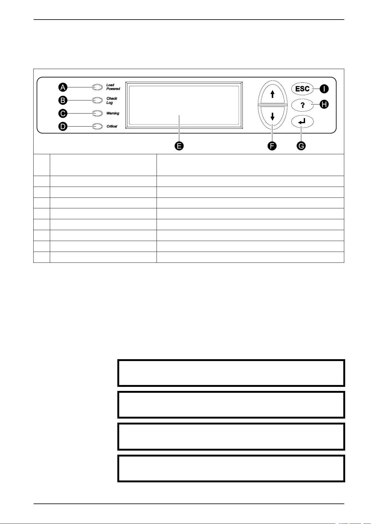
User Interface
ALoad Powered LED When this LED is green, power to the load is on. When this LED is yellow, the load
is supplied through the batteries. When this LED is flashing yellow, the unit is in
bypass.
BCheck Log LED When this LED is green, a new event has been added to the event log.
CWarning LED When this LED is yellow, there are one or more warning alarms in the system.
DCritical LED When this LED is red, there are one or more critical alarms in the system.
E LCD screen Displays alarms, status data, instructional help, and configuration items.
F Arrow keys Scrolls through and select menu items.
G Enter key Opens menu items and confirms changes to the system parameters.
H Help key Opens context-sensitive help.
IESC key Returns to the previous screen displayed.
Display Interface
Overview Screens
The overview screen is the main entrance to the user functions of the display
interface. The arrow keys take you from one screen to another. When the system is
running, the display will scroll through screens showing information about the
system and any active alarms.
NOTE: The data values shown are for example only.
No Active Alarms
System Date/Time:
28-Mar-2010 10:37:01
Volts In Volts Out
L1: xxx L1: xxx
L2: xxx L2: xxx
L3: xxx L3: xxx
Out Amps kWkVA
L1:xxx xx.xxx.x
L2:xxx xx.xxx.x
L3:xxx xx.xxx.x
Symmetra PX 160 kW
Runtime: xxhr xxmin
Capacity xxx.x%
UPS Load: xxx%
990–3015J-001 7

48, 96, and 160 kW 400 V 100 kW 208 V Overview
System Bypass State:
UPS Operation
UPS State:
On Line
NOTE: Press the enter key to go from any overview screen to the main menu
screen.
Menu Tree
The menu tree provides a quick overview of the functions and views you may
access.
UPS Power Control
UPS UPS Status
UPS Tests & Diags
UPS Configuration
Total Loading
Power Dist Modular Loading
Volt-Meter
Subfeeds
Switchgear Status
Factory
Input Contacts
Environment Output Relays
Alarm Relay Map
Env Monitoring Card
Main Menu Screen Alarms All Active Alarms
Active by Severity
Active by Type
Log View New Log Items
View Entire Log
Clear Entire Log
Network Setup
Admin Local Interface
Date/Time
Device ID
Manufacturer Data
Factory Defaults
Firmware Upgrade
Life cycle Monitor
Help
On any screen and any line, press ?for context
sensitive help. Try it now…
NOTE: The display provides access to more functions than described in this
manual. Those functions should not be accessed without the assistance of
Schneider Electric Customer Support in order to avoid unwanted load impacts. If
you by accident go beyond the functions described, press the ESC key to return to
previous screens.
8 990–3015J-001

Operation 48, 96, and 160 kW 400 V 100 kW 208 V
Operation
Operation Modes
The UPS has three operation modes: normal operation, battery operation and
static bypass operation. If the UPS system includes a PDU, a PDU with modular
batteries, or an external maintenance bypass enclosure, the mode maintenance
bypass operation also becomes available.
Normal Operation
During normal operation, the UPS converts the utility/mains supply to conditioned
power for the connected load.
Battery Operation
During battery operation, the UPS provides conditioned power to the connected
load from its batteries for a finite period. The UPS transfers to battery operation if
the utility/mains power supply becomes unavailable or is outside the predefined
limits.
Static Bypass Operation
Static bypass operation is a feature that keeps the load supplied directly from the
utility/mains supply during different scenarios on the UPS or downstream from the
UPS. In static bypass operation, the utility/mains is supplying power to the
connected load directly, bypassing all internal UPS functions.
Maintenance Bypass Operation (Optional)
The UPS can be connected to a PDU, a PDU with modular batteries, or an external
maintenance bypass enclosure that enables the user to bypass the UPS
completely for maintenance purposes that might even include replacement of the
entire UPS. In this situation, the connected load will then be fed directly from the
utility/mains supply, and there will be no conditioning of the supply or battery
backup of the load.
Operation Procedures
Breakers/Switches in the System
Q1 UPS input
Q2 UPS output
Q3 Maintenance bypass
Q5 Static bypass input (only in dual utility/mains systems)
NOTE: If the system does not contain a PDU or PDU with modular batteries, the
Q1, Q2, and Q3 switches and the Q5 breaker (if present) should be located in an
optional external maintenance bypass enclosure. See the documentation included
with the maintenance bypass enclosure for additional information.
990–3015J-001 9
48, 96, and 160 kW 400 V 100 kW 208 V Operation
Perform a Total Power Off
NOTICE
RISK OF LOAD DROP
This procedure will disconnect the load.
Failure to follow these instructions can result in equipment damage.
NOTE: If shutdown via the display is disabled, then you cannot perform this
procedure and the message: Command not allowed, UPS configured to never
shutdown appears. If you want to enable shutdown via the display, this is done by
a Schneider Electric field service engineer.
1. Select UPS > UPS Power Control > Turn UPS Off and press the enter key.
→ Turn UPS Off
Reboot UPS
UPS into Bypass
UPS to Sleep
2. Select No, Don’t Notify to shut down without delay and press the enter key.
NOTE: This action will cut all power to the load without shutting it down first. If
you want to shut down the servers first, then choose Yes, Notify Servers.
Note that this function is only available for servers with PowerChute.
Notify PowerChute ?
Cancel
Yes, Notify Servers
→ No, Don’t Notify
3. Confirm YES, Turn UPS Off and press the enter key.
Turn UPS off
Without Server
Notification?
> NO, ABORT
→> YES, Turn UPS Off
4. Wait for the UPS to turn off.
Turning UPS off,
please wait…
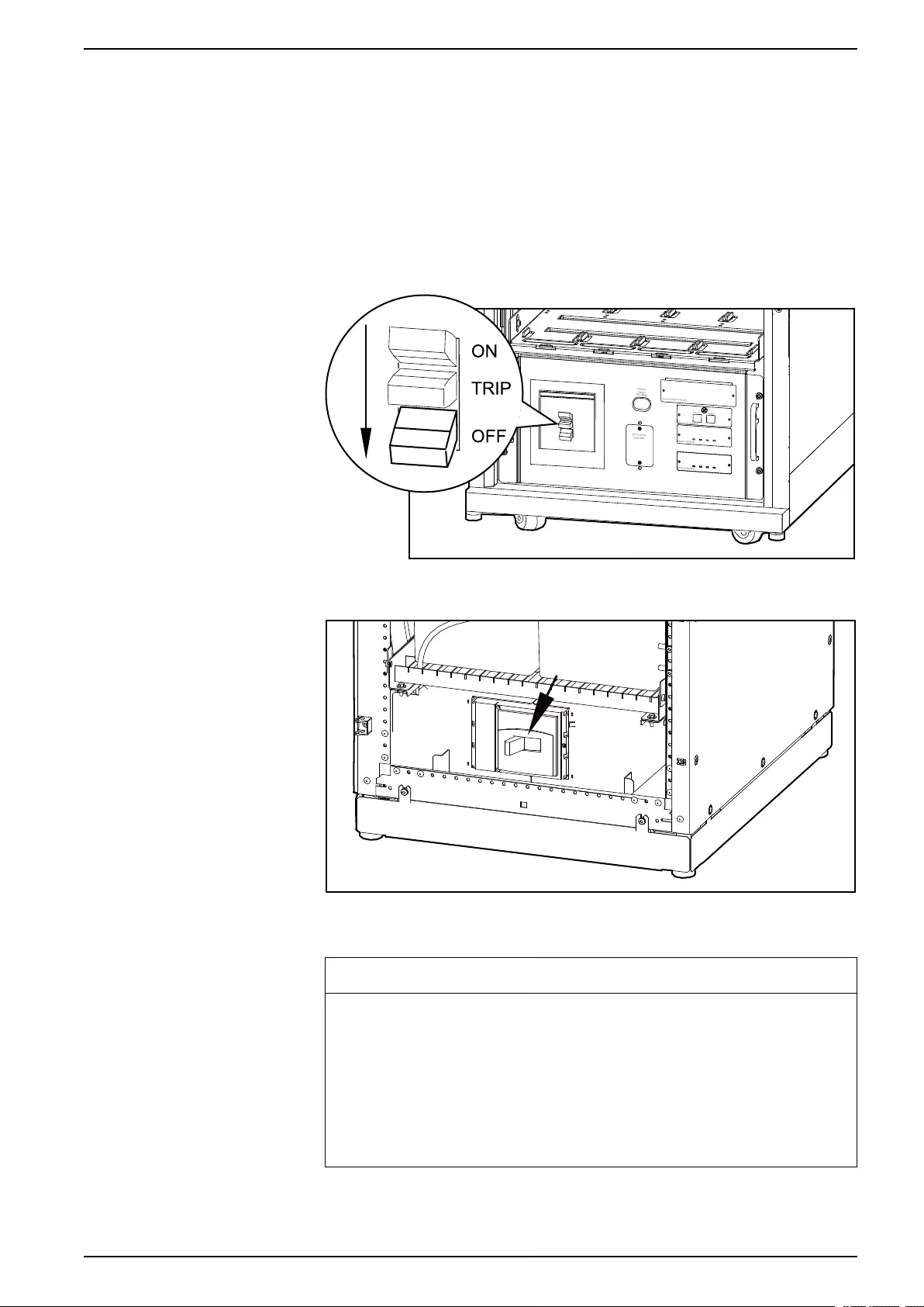
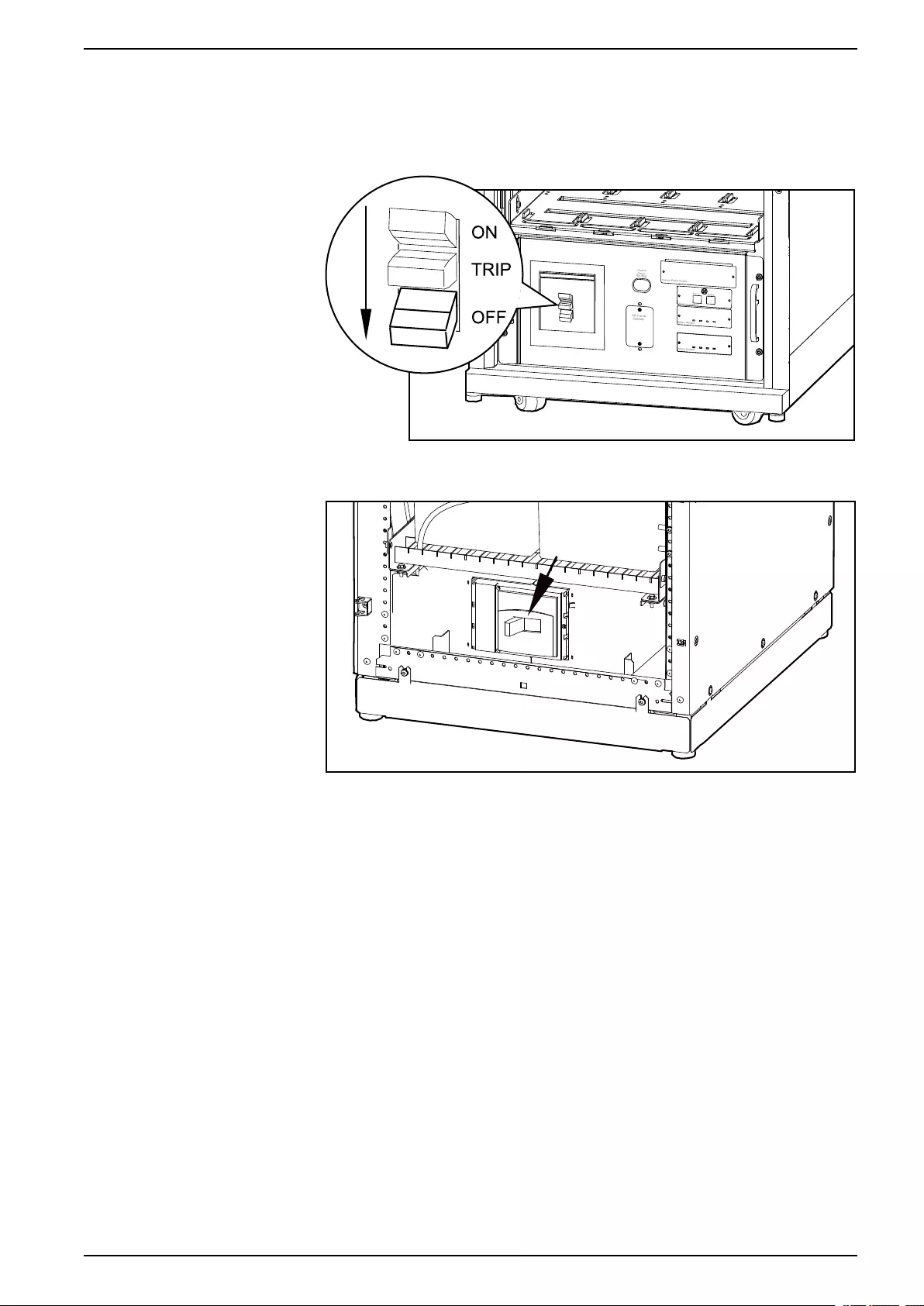
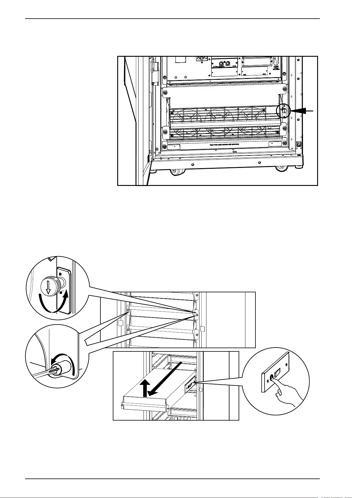
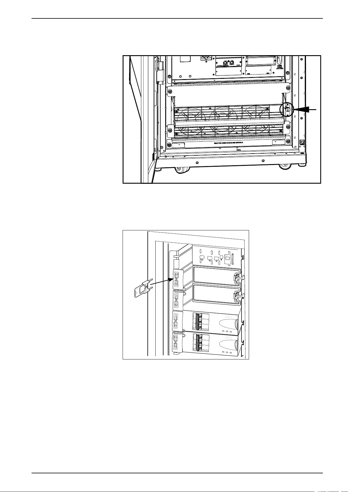
5. Set the UPS SYSTEM ENABLE switch to the OFF position.
Front View of the UPS
10 990–3015J-001
Operation 48, 96, and 160 kW 400 V 100 kW 208 V
6. Set the Q2 switch to the OFF position.
7. Set the Q1 switch to the OFF position.
8. Set the Q5 breaker to the OFF position (if applicable).
9. Verify that the maintenance bypass switch (Q3) is in the OFF position.
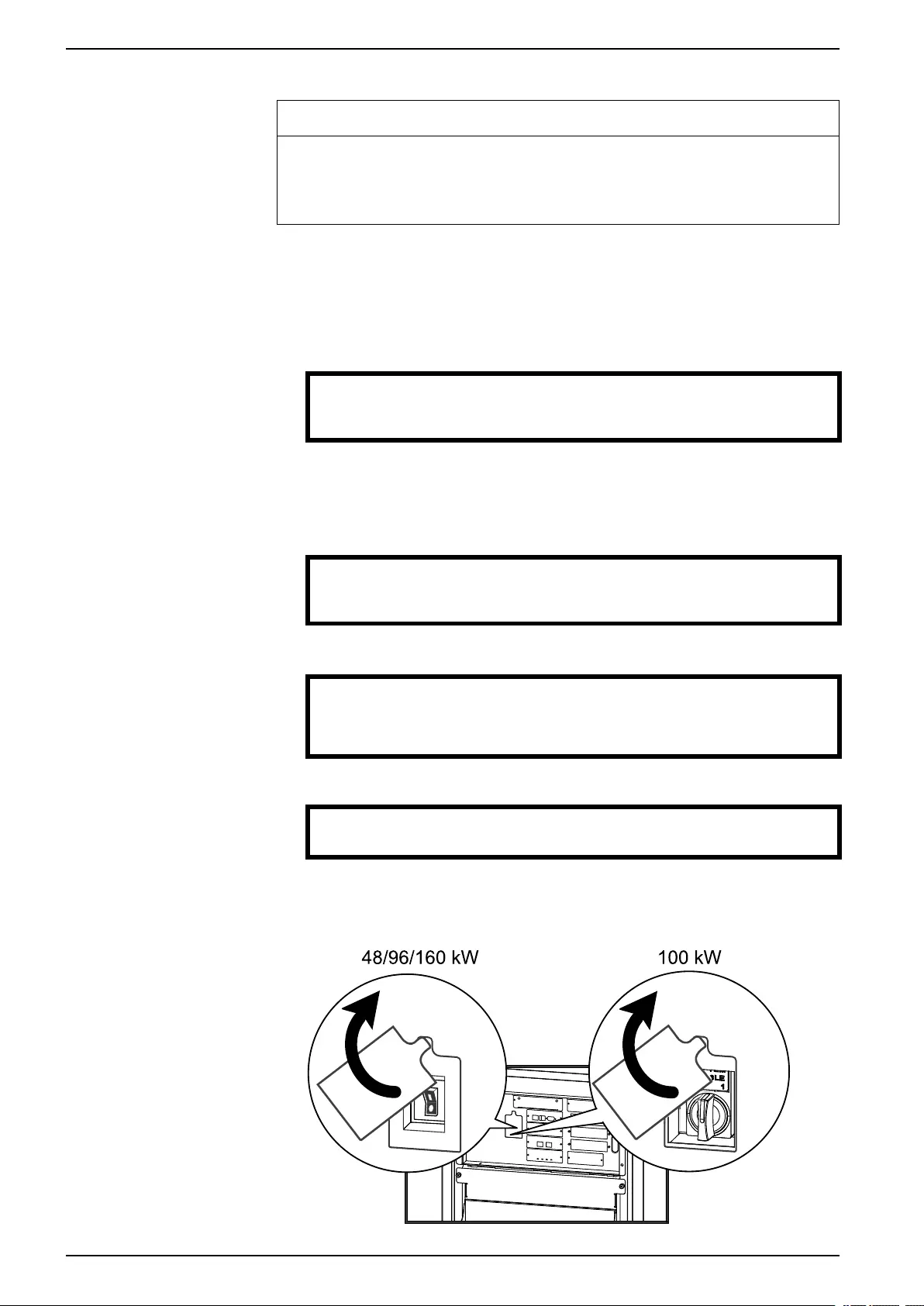
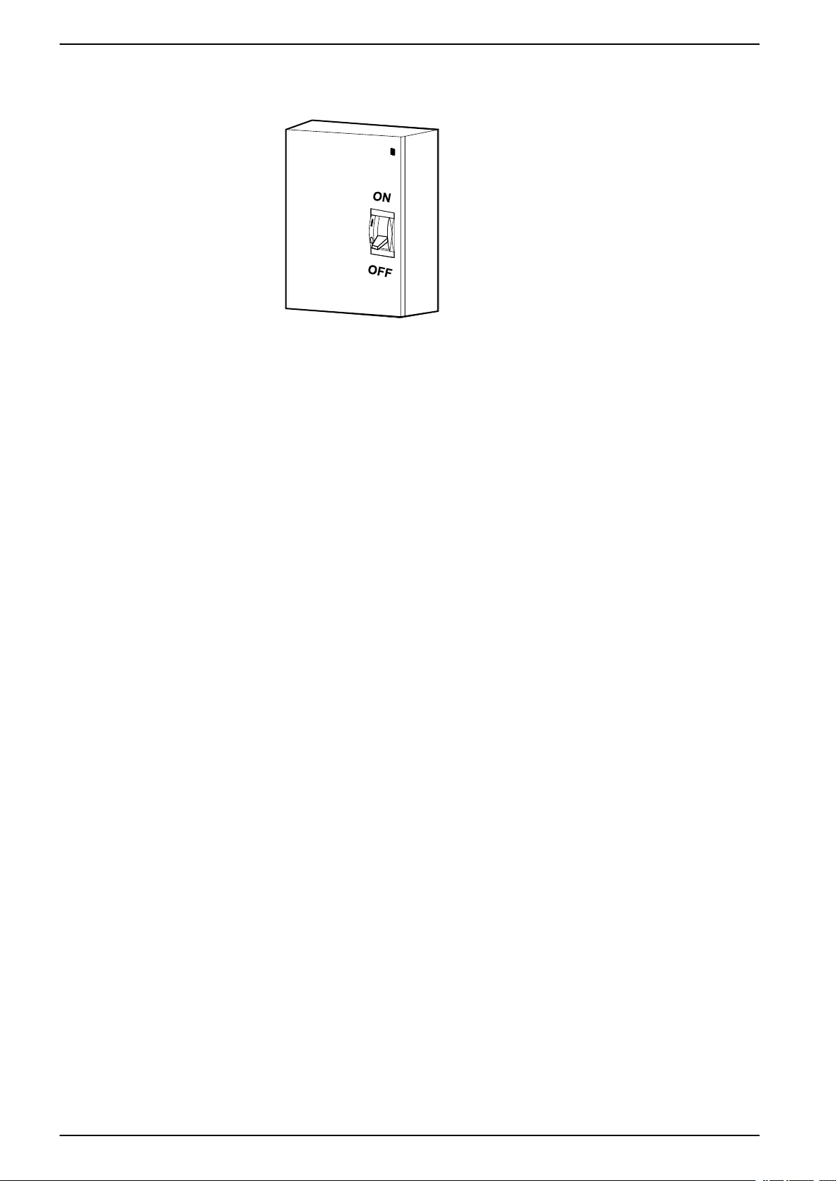
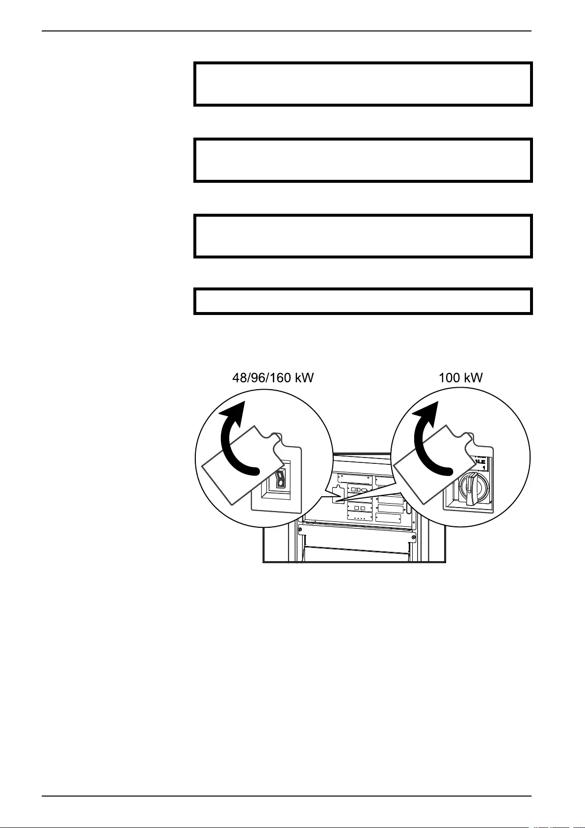
10. Set the DC DISCONNECT switch to the OFF position on all battery cabinets
and the PDU with modular batteries (if applicable) and on the UPS (only for
Symmetra PX 48 kW) .
Modular Battery Cabinets/PDU with Modular Batteries
Classic Battery Cabinet
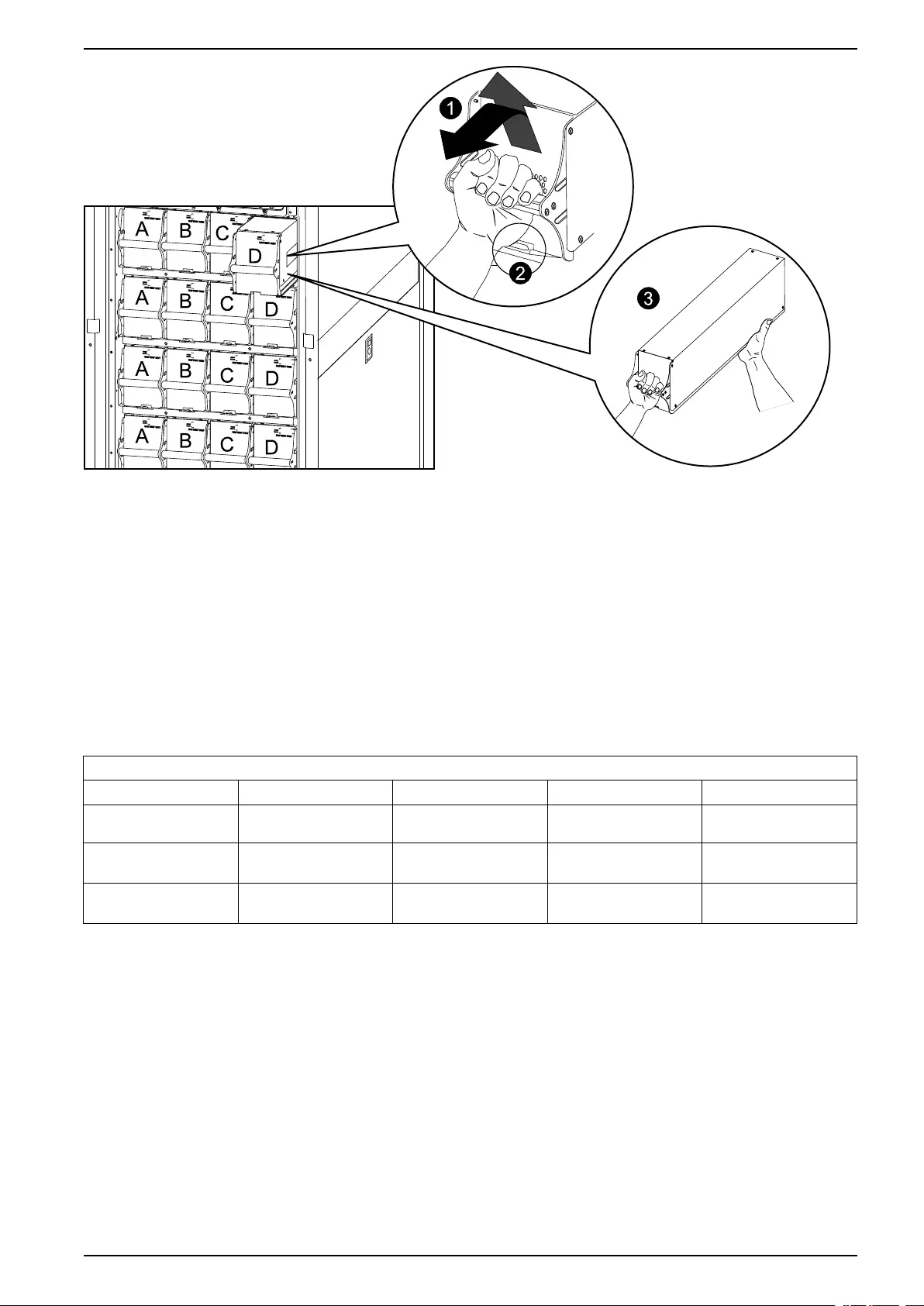
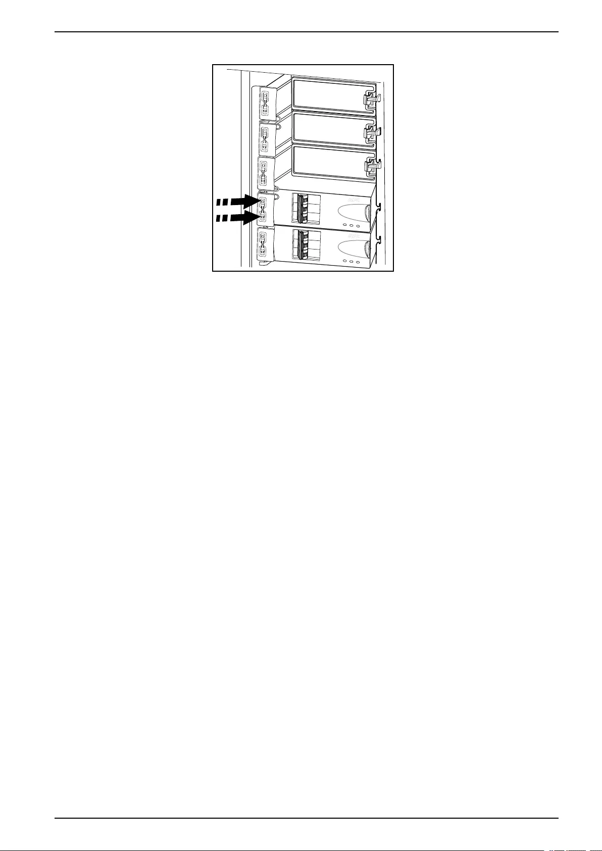
11. Disconnect all battery units by removing them (all battery types) or pulling
them out to the red disconnect line (modular batteries only).
NOTICE
RISKOF TILTING AND MODULAR BATTERY DAMAGE
To ensure that the UPS cabinet and the modular battery cabinet does not
tip, do not pull out the modular battery units beyond the red disconnect line.
If you intend to completely remove the modular battery units, remove them
from the UPS cabinet and modular battery cabinets one at a time. If you
don’t pull the modular battery units out to the red disconnect line, this could
cause deep discharge/damage to the modular batteries.
Failure to follow these instructions can result in equipment damage.
990–3015J-001 11
48, 96, and 160 kW 400 V 100 kW 208 V Operation
12. Set the upstream utility/mains power to the OFF or LOCKED OUT position. If
the UPS has a dual utility/mains supply, set both supplies to the OFF or
LOCKED OUT position.
13. Measure bypass/output DC and utility/mains to ensure that the system is
completely powered off.
Start the System after Total Power Off
NOTE: If batteries/battery units have been removed or disconnected for the total
power off, reinsert and reconnect them before starting up the system.
1. Set the upstream utility/mains power to the ON or LOCKED IN position. If the
UPS has a dual utility/mains supply, set both supplies to the ON or LOCKED
IN position.
12 990–3015J-001
Operation 48, 96, and 160 kW 400 V 100 kW 208 V
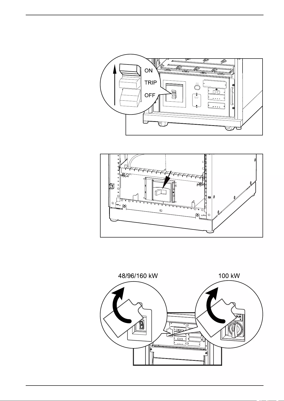
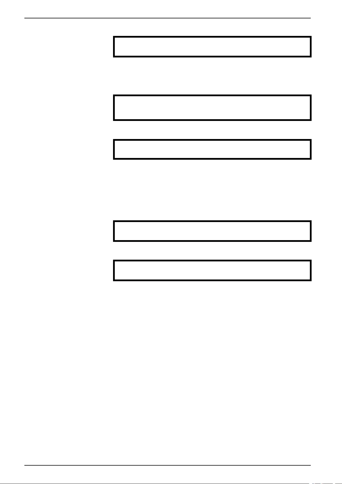
2. Set the DC DISCONNECT switch to the ON position on all modular battery
cabinets and the PDU with modular batteries (if applicable) and on the UPS
(only for Symmetra PX 48 kW).
Modular Battery Cabinets/PDU with Modular Batteries
Classic Battery Cabinet
3. Set the Q1 switch to the ON position.
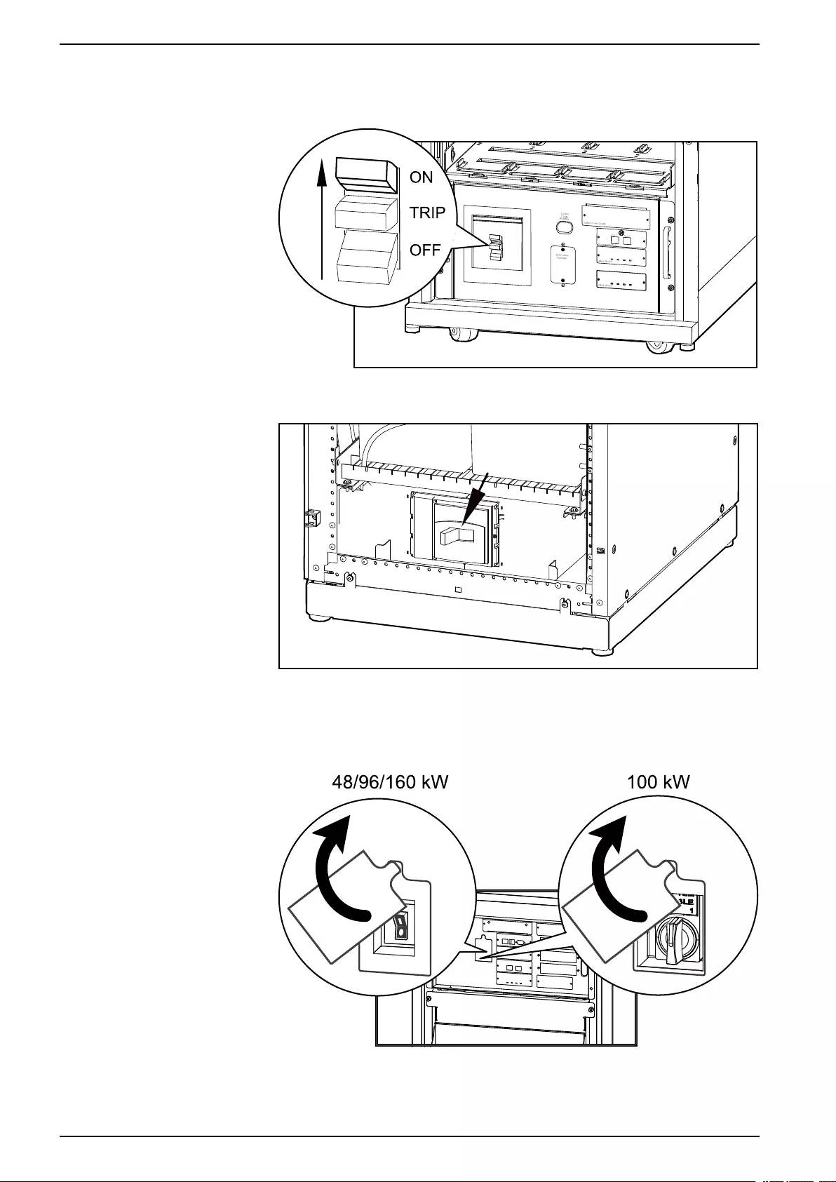
4. Set the SYSTEM ENABLE switch on the UPS to the ON position.
Front View of UPS
NOTE: Wait approximately two minutes for the system to start.
990–3015J-001 13

48, 96, and 160 kW 400 V 100 kW 208 V Operation
5. Set the Q5 breaker to the ON position (if applicable).
NOTE: The H2 LED next to the Q2 switch will turn on, indicating that the Q2
switch can be operated.
6. Set the Q2 switch on the PDU, PDU with modular batteries, or the external
maintenance bypass to the ON position.
7. Select UPS > UPS Power Control > Turn UPS On and press the enter key.
→ Turn UPS On
UPS On Into Bypass
8. Confirm by selecting Yes, Turn UPS On and press the enter key.
Confirm:
Turn UPS On ?
>NO, ABORT
→ >Yes, Turn UPS On
9. Wait for the UPS to turn on.
Turning UPS on,
Please wait…
Turn the UPS Load Off
NOTE: If shutdown via the display is disabled, then you cannot perform this
procedure and the message: Command not allowed, UPS configured to never
shutdown appears. If you want to enable shutdown via the display, this is done by
a Schneider Electric field service engineer.
1. Select UPS > UPS Power Control > Turn UPS Off and press the enter key.
→ Turn UPS Off
Reboot UPS
UPS Into Bypass
UPS To Sleep
2. Select No, Don’t Notify and press the enter key.
NOTE: This action will cut all power to the load without shutting it off first. If
you want to shut down the servers first, then choose Yes, Notify Servers.
Note that this function is only available for servers with PowerChute.
Notify PowerChute?
Cancel
Yes, Notify Servers
→ No, Don’t Notify
3. Confirm YES, Turn UPS Off and press the enter key.
Turn UPS Off Without
Server Notification?
>NO, ABORT
→ YES, Turn UPS Off
4. Wait for the UPS to turn off.
Turning UPS off,
please wait…
14 990–3015J-001

Operation 48, 96, and 160 kW 400 V 100 kW 208 V
Turn the UPS Load On
1. Select UPS > UPS Power Control > Turn UPS On and press the enter key.
→ Turn UPS On
UPS On Into Bypass
2. Confirm by selecting Yes, Turn UPS On and press the enter key.
Confirm:
Turn UPS On?
>NO, ABORT
→ >YES, Turn UPS On
3. Wait for the UPS to turn the load on.
Turning UPS on,
please wait…
Transfer the UPS into Maintenance Bypass Operation
NOTE: If shutdown via the display is disabled, then you cannot perform this
procedure and the message: Command not allowed, UPS configured to never
shutdown appears. If you want to enable shutdown via the display, this is done by
a Schneider Electric field service engineer.
1. Select UPS > UPS Power Control > UPS into Bypass and press the enter
key.
Turn UPS Off
Reboot UPS
→ UPS into Bypass
UPS to Sleep
2. Select Yes, Into Bypass and press the enter key.
Confirm:
UPS into Bypass?
NO, ABORT
→ YES, Into Bypass
3. Wait for the transfer to complete.
Putting UPS into
Bypass, please
wait….
4. Confirm that the transfer to bypass is complete.
NOTE: The H3 LED next to the Q3 switch will turn on, indicating that the Q3
switch can be operated.
UPS is now in
Bypass.
Press any key….
5. Set the Q3 switch to the ON position.
NOTE: The H2 LED beside the Q2 switch will turn on, indicating that the Q2
switch can be operated.
6. Set the Q2 switch to the OFF position.
990–3015J-001 15
48, 96, and 160 kW 400 V 100 kW 208 V Operation
7. Select UPS > UPS Power Control > Turn UPS Off and press the enter key.
→ Turn UPS Off
Reboot UPS
UPS into Bypass
UPS to Sleep
8. Select No, Don’t Notify and press the enter key.
Notify PowerChute ?
Cancel
Yes, Notify Servers
→ No, Don’t Notify
9. Confirm by selecting YES, Turn UPS Off and press the enter key.
Turn UPS Off Without
Server Notification?
>NO, ABORT
→ >YES, Turn UPS Off
10. Wait for the UPS to turn off.
Turning UPS off,
please wait….
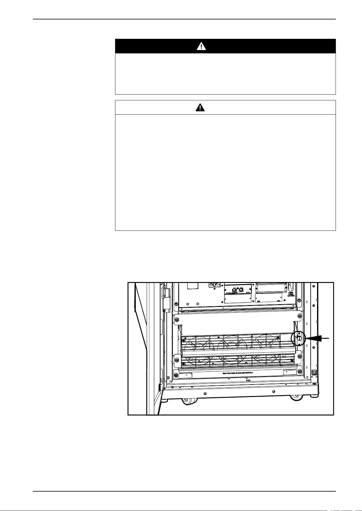
11. Set the UPS SYSTEM ENABLE switch to the OFF position.
Front View of UPS
12. Set the Q1 switch to the OFF position.
13. Set the Q5 breaker to the OFF position (if applicable).
16 990–3015J-001
Operation 48, 96, and 160 kW 400 V 100 kW 208 V
14. Set the DC DISCONNECT switch to the OFF position on all modular battery
cabinets and the PDU with modular batteries (if applicable) and on the UPS
(only for Symmetra PX 48 kW).
Modular Battery Cabinets/PDU with Modular Batteries
Classic Battery Cabinet
Return to Normal Operation from Maintenance Bypass Operation
1. Set the DC DISCONNECT switch to the ON position on all modular battery
cabinets and the PDU with modular batteries (if applicable) and on the UPS
(only for Symmetra PX 48 kW).
990–3015J-001 17
48, 96, and 160 kW 400 V 100 kW 208 V Operation
2. Set the Q1 switch to the ON position.
Modular Battery Cabinet/PDU with Modular Batteries
Classic Battery Cabinet
3. Set the SYSTEM ENABLE switch on the UPS to the ON position.
NOTE: Wait approximately two minutes for the system to start.
Front View of UPS
4. Set the Q5 breaker to the ON position (if applicable).
18 990–3015J-001

Operation 48, 96, and 160 kW 400 V 100 kW 208 V
5. Select UPS > UPS Power Control > UPS On into Bypass and press the
enter key.
Turn UPS On
→ UPS On into Bypass
6. Select Continue Turn On and press the enter key.
Battery back-up not
available in bypass!
>Cancel
→ >Continue Turn On
7. Confirm by selecting Yes, On Into Bypass and press the enter key.
Confirm:
UPS on Into Bypass
>NO, ABORT
→ >Yes, On Into Bypass
8. Wait for the UPS to turn the load on.
Turning UPS on Into
Bypass.
Please wait…
9. The UPS is now ON.
NOTE: The H2 LED next to the Q2 switch will turn on, indicating that the Q2
switch can be operated.
UPS’s output is now
in bypass
Press any key…
10. Set the Q2 switch on the PDU, PDU with modular batteries or the external
maintenance bypass enclosure to the ON position.
NOTE: The H3 LED next to the Q3 switch will turn on, indicating that the Q3
switch can be operated.
11. Set the Q3 switch to the OFF position.
12. Use the display interface to transfer the UPS out of bypass:
13. Select UPS > UPS Power Control > UPS out of Bypass and press the enter
key.
Turn UPS Off
Reboot UPS
→ UPS out of Bypass
UPS to Sleep
14. Confirm by selecting Yes, Out of Bypass and press the enter key.
Confirm:
UPS out of Bypass?
>NO, ABORT
→ >YES, Out of Bypass
15. Wait for the UPS to transfer out of bypass.
Putting UPS out of
Bypass, please
wait….
990–3015J-001 19
48, 96, and 160 kW 400 V 100 kW 208 V Operation
16. The UPS is now out of bypass and is in normal operation.
UPS is now out of
bypass
Press any key….
View the Status Screens
1. Select UPS > UPS Status and press the enter key.
UPS Power Control
→ UPS Status
UPS Tests & Diags
UPS Configuration
2. Use the arrow keys to navigate through the status screens.
Symmetra PX 160 kW
Status: On Line
No UPS Alarms
View the Log Screen
1. Select Log and press the enter key.
2. Select View New Log Items to see new log items when the Check Log LED
is green and press the enter key. To see historical events select the View
Entire Log and press the enter key.
→ View New Log Items
View Entire Log
Clear Entire Log
3. Use the arrow keys to navigate through the log screens.
Log Item ≥1 of 2
03/14/07 10:37:02
<Description>
20 990–3015J-001

Configuration 48, 96, and 160 kW 400 V 100 kW 208 V
Configuration
System Settings
Set Up the Network
1. Select Admin > Network Setup > Mode and press the enter key.
Stat:
→ Mode:
IP:
SM:
2. Select Fixed IP Addr to give a specific IP address to the UPS system or select
one of the other two methods to obtain an IP address. In this example Fixed
IP Addr mode is selected.
→ Fixed IP Addr
DHCP Only
BOOTP Only
3. Select IP (Internet Protocol),SM (Subnet Mask), and GW (GateWay) and
change the settings using the arrow keys. Press the enter key to confirm the
changes.
→ IP:
→ SM:
→ GW:
Change the Display Interface Settings
1. Select Admin > Local Interface > Display Behaviour and press the enter
key.
Local Password
→ Display Behaviour
Alarm Beeper
2. Select Contrast, Key Click, Beeper Volume, or Check Log Light and
change the settings using the arrow keys. Press the enter key to save the
changes.
→ Contrast ≥4
Key Click ≥On
Beeper Volume > High
Check Log Light
Change the Date and Time
1. Select Admin > Date/Time and press the enter key.
Network Setup
Local Interface
→ Date/Time
Device ID
2. Select Date or Time and change the settings by using the arrow keys. Press
the enter key to save the changes.
Mode: Manual
Format: mm/dd/yyyy
Date: xx/xx/xxxx
Time: xx:xx:xx
990–3015J-001 21

48, 96, and 160 kW 400 V 100 kW 208 V Configuration
Set Up Capacity Parameters for Classic Battery
NOTE: It is necessary to set up the capacity parameters for UPSs with classic
batteries. This is not necessary for UPSs with modular batteries.
1. Select UPS > UPS Configuration > Other and press the enter key.
UPS Configuration
Shutdown Output
Alarms Bypass
Default → Other
2. Select BatFrmAmpHour and input the battery capacity C10Ah and press the
enter key to confirm.
Self Test: xx days
UPS ID: XXXXX
→ BatFrmAmpHour: C10AH
Charger Rate: xxx
Configure Input Contacts
1. Select Environment > Input Contacts and press the enter key.
→ Input Contacts
Output Relays
Alarm Relay Map
2. Select desired input contact, 1 through 4, select Configuration, and press the
enter key.
Input Contact:xof4
<contact name>
Status: Normal
→ Configuration
3. Change the settings for Name/Location,Alarms,Severity, and Normal
state.
Name/Location x
Alarms: Enabled
Severity: Critical
Normal: Open
Configure Output Relays
1. Select Environment > Output Relays and press the enter key.
Input Contacts
→ Output Relays
Alarm Relay Map
2. Select desired output relay, 1 through 4, select Configuration, and press the
enter key.
Output Relay:xof4
<relay name>
Status: Closed
→ Configuration
3. Change the settings for Name and Normal position for the selected output
relay.
Relay x Name
<output relay>
Normal: Closed
22 990–3015J-001
Maintenance 48, 96, and 160 kW 400 V 100 kW 208 V
Maintenance
Life Cycle Monitoring (LCM)
The Life Cycle Monitoring (LCM) function provides UPS preventive maintenance
advice. It is currently only supported on Symmetra PX 100 kW UPSs.
The display shows the following three messages:
Display Message Description – corrective action
Contact Schneider Electric for Secure Startp-Up Startup check is recommended. Please call the Schneider Electric
support center.
Warranty Expiring Soon The end of the contractual legal warranty. Please call the Schneider
Electric support center.
Technical Check Recommended Regular maintenance requirements and the end of service life
consumable components. Please call the Schneider Electric support
center.
In addition to these messages, the Warning LED lights up and the buzzer sounds.
These messages can be disabled by choosing Admin >Life Cycle Monitor >
Settings >Yes. This will cause the Warning LED to go out, the buzzer to stop and
remove any Life Cycle Monitoring messages.
Parts Replacement
DANGER
HAZARD OF ELECTRIC SHOCK, EXPLOSION, OR ARC FLASH
Apply appropriate personal protective equipment (PPE) and follow safe electrical
work practices for all part replacement procedures.
Failure to follow these instructions will result in death or serious injury.
Determine if you need a Replacement Part
To determine if you need a replacement part, contact Schneider Electric and follow
the procedure below so that the representative can assist you promptly:
1. In the event of an alarm condition, scroll through the alarm lists, record the
information, and provide it to the representative.
2. Write down the serial number of the unit so that you will have it easily
accessible when you contact Schneider Electric.
3. If possible, call Schneider Electric from a telephone that is within reach of the
display so that you can gather and report additional information to the
representative.
4. Be prepared to provide a detailed description of the problem. A representative
will help you solve the problem over the telephone, if possible, or will assign a
return material authorization (RMA) number to you. If a module is returned to
Schneider Electric, this RMA number must be clearly printed on the outside of
the package.
5. If the unit is within the warranty period and has been started up by Schneider
Electric, repairs or replacements will be performed free of charge. If it is not
within the warranty period, there will be a charge.
6. If the unit is covered by a Schneider Electric service contract, have the
contract available to provide information to the representative.
990–3015J-001 23
48, 96, and 160 kW 400 V 100 kW 208 V Maintenance
Return Parts to Schneider Electric
Call Schneider Electric to obtain an RMA number.
To return an inoperable part to Schneider Electric, pack the module in the original
shipping materials, and return it by insured, prepaid carrier. The customer support
representative will provide the destination address. If you no longer have the
original shipping materials, ask the representative about obtaining a new set. Pack
the module properly to avoid damage in transit. Never use styrofoam beads or
other loose packaging materials when shipping a module. The module may settle
in transit and become damaged. Enclose a letter in the package with your name,
RMA number, address, a copy of the sales receipt, description of the problem, a
phone number, and a confirmation for payment (if necessary).
NOTE: Damages sustained in transit are not covered under warranty.
Replacement Parts
DANGER
HAZARD OF ELECTRICAL SHOCK, EXPLOSION OR ARC FLASH
All safety instructions in this document must be read, understood and followed.
Failure to follow these instructions will result in death or serious injury.
DANGER
HAZARD OF ELECTRICAL SHOCK, EXPLOSION OR ARC FLASH
Only trained personal familiar with the construction and operation of the
equipment, as well as the electrical and mechanical hazards involved, may
install and remove system components.
Failure to follow these instructions will result in death or serious injury.
NOTE: A maximum of two smart slots can be used.
Part Part number
16 kW power module for 48, 96 and 160 kW 400 V SYPM10K16H
10 kW power module for 100 kW 208V, high efficiency SYPM10KF2
Modular battery string (four battery units) SYBT9-B4
Modular battery unit SYBTU2-PLP
SmartSlot relay I/O module (option) AP9613
Modbus/Jbus interface card (option) AP9622
Network management card (option) Go to www.apc.com for a list of network management cards
Power distribution module Go to www.apc.com for a complete list of breakers
24 990–3015J-001
Maintenance 48, 96, and 160 kW 400 V 100 kW 208 V
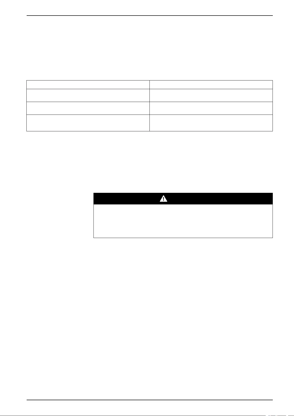
Replace a Smart Slot Card
A. Only the cards in these two locations can be replaced.
1. Loosen the two screws on the sides of the card and carefully pull it out of the
cabinet.
2. Install the new card and fasten it with the two screws.
NOTE: The UPS has an embedded network management card.
Replace a Power Module
There are two options for replacing a power module:
1. Replace a Power Module with System in Maintenance Bypass Operation,
page 25.
2. Replace a Power Module with System in Battery Operation, page 27.
Replace a Power Module with System in Maintenance Bypass Operation
DANGER
HAZARD OF ELECTRIC SHOCK, EXPLOSION, OR ARC FLASH
Electrical equipment must be installed, operated, serviced, and maintained only
by qualified personnel.
Failure to follow these instructions will result in death or serious injury.
DANGER
HAZARD OF ELECTRIC SHOCK, EXPLOSION, OR ARC FLASH
If power modules are removed, blanking panels must be installed to restrict
access to live parts. Blanking panels can be obtained from Schneider Electric.
Failure to follow these instructions will result in death or serious injury.
CAUTION
HAZARD OF PERSONAL INJURY
Two persons are required for lifting a power module.
Failure to follow these instructions can result in injury or equipment
damage.
990–3015J-001 25
48, 96, and 160 kW 400 V 100 kW 208 V Maintenance
1. Turn the UPS into maintenance bypass operation following the procedure
Transfer the UPS into Maintenance Bypass Operation, page 15.
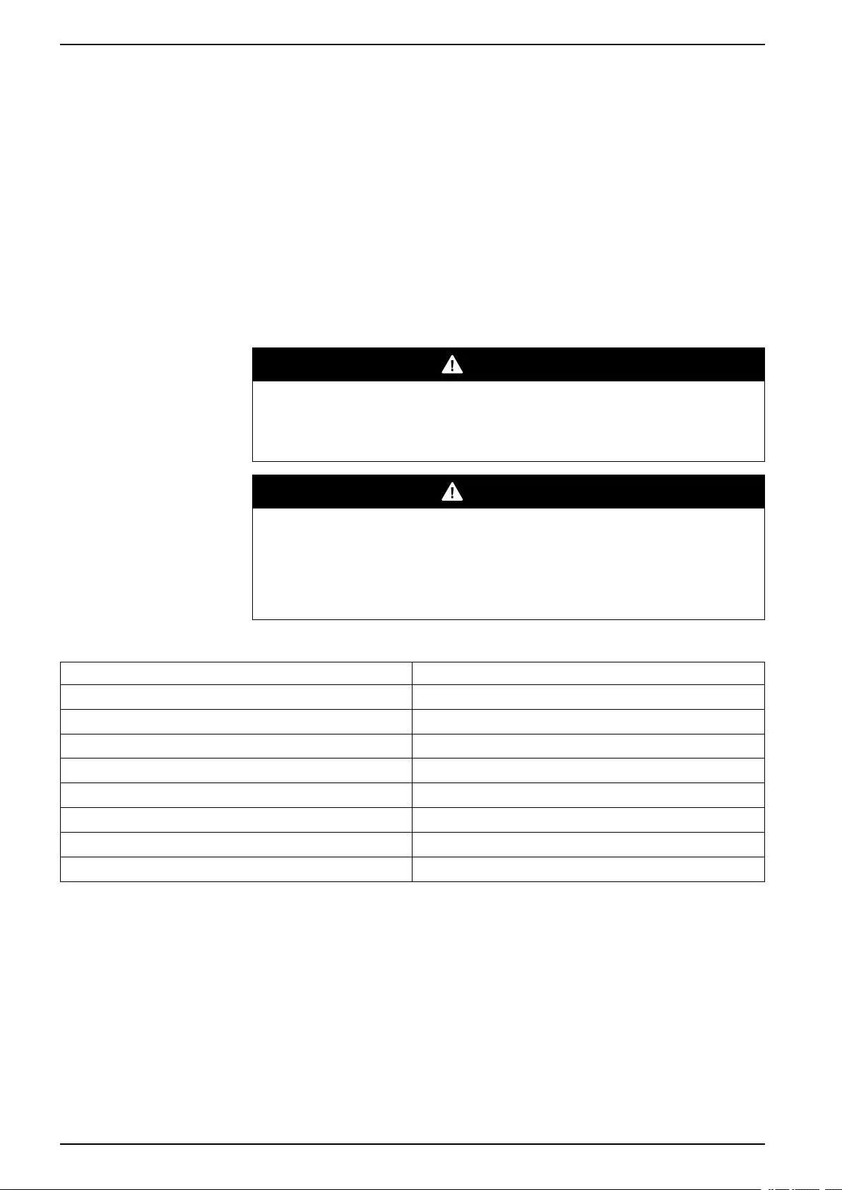
2. Turn the enable switch to the unlocked position on the power module.
3. Unscrew the spring-activated knobs on both sides of the power module.
4. Pull the power module up and out of the cabinet as far as the lock mechanism
allows.
5. Release the lock by pressing the black plastic tab on both sides of the module.
6. Pull the module out of the cabinet.
7. Carefully guide the new power module completely into the cabinet.
CAUTION
HAZARD OF EQUIPMENT DAMAGE
Do not attempt to insert the power module using excessive force, but make
sure that it is in place before continuing.
Failure to follow these instructions can result in injury or equipment
damage.
8. Tighten the spring-activated knobs on both sides of the power module to
ensure proper contact.
9. Turn the enable switch to the locked position on the power module.
CAUTION
HAZARD OF EQUIPMENT DAMAGE
Tighten the spring-activated knobs before turning the enable switch to
ensure that the module makes proper contact within the unit. The power
module will not operate unless the enable switch is engaged. If it has not
engaged, take out the power module and insert it again
Failure to follow these instructions can result in injury or equipment
damage.
26 990–3015J-001
Maintenance 48, 96, and 160 kW 400 V 100 kW 208 V
10. Return to normal operation by following the procedure Return to Normal
Operation from Maintenance Bypass Operation, page 17.
Replace a Power Module with System in Battery Operation
DANGER
HAZARD OF ELECTRIC SHOCK, EXPLOSION, OR ARC FLASH
Electrical equipment must be installed, operated, serviced, and maintained only
by qualified personnel.
Failure to follow these instructions will result in death or serious injury.
DANGER
HAZARD OF ELECTRIC SHOCK, EXPLOSION, OR ARC FLASH
If power modules are removed, blanking panels must be installed to restrict
access to live parts. Blanking panels can be obtained from Schneider Electric.
Failure to follow these instructions will result in death or serious injury.
CAUTION
HAZARD OF PERSONAL INJURY
Two persons are required for lifting a power module.
Failure to follow these instructions can result in injury or equipment
damage.
CAUTION
RISK OF LOAD DROP
Before replacing a power module with this procedure, verify that:
• The remaining power modules can support the load. If not, then contact
Schneider Electric.
• The batteries are fully charged and that the UPS runtime displayed on the
UPS status screen is sufficient to support the load during the replacement of
the power module. If sufficient UPS runtime is not available, use the
procedure Replace a Power Module with System in Maintenance Bypass
Operation, page 25 for replacing the power module.
Failure to follow these instructions can result in injury or equipment
damage.
1. Unpack the new power module.
2. Open the UPS input breaker (Q1).
Verify that the system is in battery operation. The Load Powered LED on the
display should be lit in yellow. Verify that there are no alarms on the display,
except for the inoperable power module alarm and the input AC out of
tolerance alarm.
CAUTION
RISK OF LOAD DROP
The remaining steps of this procedure must be completed within the
remaining runtime available.
Failure to follow these instructions can result in injury or equipment
damage.
990–3015J-001 27
48, 96, and 160 kW 400 V 100 kW 208 V Maintenance
3. If the UPS has dual mains supply, open the bypass input breaker Q5 (if
available). If the UPS does not have a Q5 breaker, turn the enable switch of
the static switch module to the left to the unlocked position to disable the static
switch module.
4. Identify the power module that needs to be removed or replaced. An
inoperable power module can be identified via the display or red LED
indication in the bottom right corner of the power module.
5. Turn the enable switch to the unlocked position on the power module.
6. Unscrew the spring-activated knobs on both sides of the power module.
7. Pull the power module up and out of the cabinet as far as the lock mechanism
allows.
8. Release the lock by pressing the black plastic tab on both sides of the power
module.
28 990–3015J-001
Maintenance 48, 96, and 160 kW 400 V 100 kW 208 V
9. Pull the power module out of the cabinet.
CAUTION
RISK OF LOAD DROP
Ensure that the UPS runtime on the UPS status screen is sufficient to
support the load for completion of the remaining steps of this procedure. If
that is not the case, turn the system back to normal operation and wait for
the batteries to recharge.
Failure to follow these instructions can result in injury or equipment
damage.
10. Carefully guide the new power module completely into the system.
11. Tighten the spring-activated knobs on both sides of the power module to
ensure proper contact.
12. Turn the enable switch to the locked position on the power module.
CAUTION
HAZARD OF EQUIPMENT DAMAGE
Tighten the spring-activated knobs before turning the enable switch to
ensure that the module makes proper contact within the unit. The power
module will not operate unless the enable switch is engaged. If it has not
engaged, take out the power module and insert it again
Failure to follow these instructions can result in injury or equipment
damage.
13. If the UPS has dual mains supply, close the bypass input breaker Q5 (if
available). If the system does not have a Q5 breaker, turn the enable switch of
the static switch module to the right to enable the static switch module.
14. Close the UPS input breaker Q1.
15. Verify that the UPS Mode is Normal Operation. The Load Powered LED on
the display should be lit green.
Replace a Modular Battery in a Modular Battery Cabinet
DANGER
HAZARD OF ELECTRIC SHOCK, EXPLOSION OR ARC FLASH
• Battery circuit breakers must be installed according to the specifications and
requirements as defined by Schneider Electric.
• Servicing of batteries must only be performed or supervised by qualified
personnel knowledgeable of batteries and the required precautions. Keep
unqualified personnel away from batteries.
• Do not dispose of batteries in a fire as they can explode.
• Do not open, alter, or mutilate batteries. Released electrolyte is harmful to the
skin and eyes. It may be toxic.
Failure to follow these instructions will result in death or serious injury.
990–3015J-001 29
48, 96, and 160 kW 400 V 100 kW 208 V Maintenance
DANGER
HAZARD OF ELECTRIC SHOCK, EXPLOSION, OR ARC FLASH
Batteries can present a risk of electric shock and high short-circuit current. The
following precautions must be observed when working on batteries
• Remove watches, rings, or other metal objects.
• Use tools with insulated handles.
• Wear protective glasses, gloves and boots.
• Do not lay tools or metal parts on top of batteries.
Failure to follow these instructions will result in death or serious injury.
WARNING
RISK OF EQUIPMENT DAMAGE
• When replacing batteries, always replace with the same type and number of
batteries or battery packs.
• Wait until the system is ready to be powered up before installing batteries in
the system. The time duration from battery installation until the UPS system
is powered up must not exceed 72 hours or 3 days.
• Batteries must not be stored more than six months due to the requirement of
recharging. If the UPS system remains de-energized for a long period, we
recommend that you energize the UPS system for a period of 24 hours at
least once every month. This charges the batteries, thus avoiding irreversible
damage.
Failure to follow these instructions can result in death, serious injury, or
equipment damage.
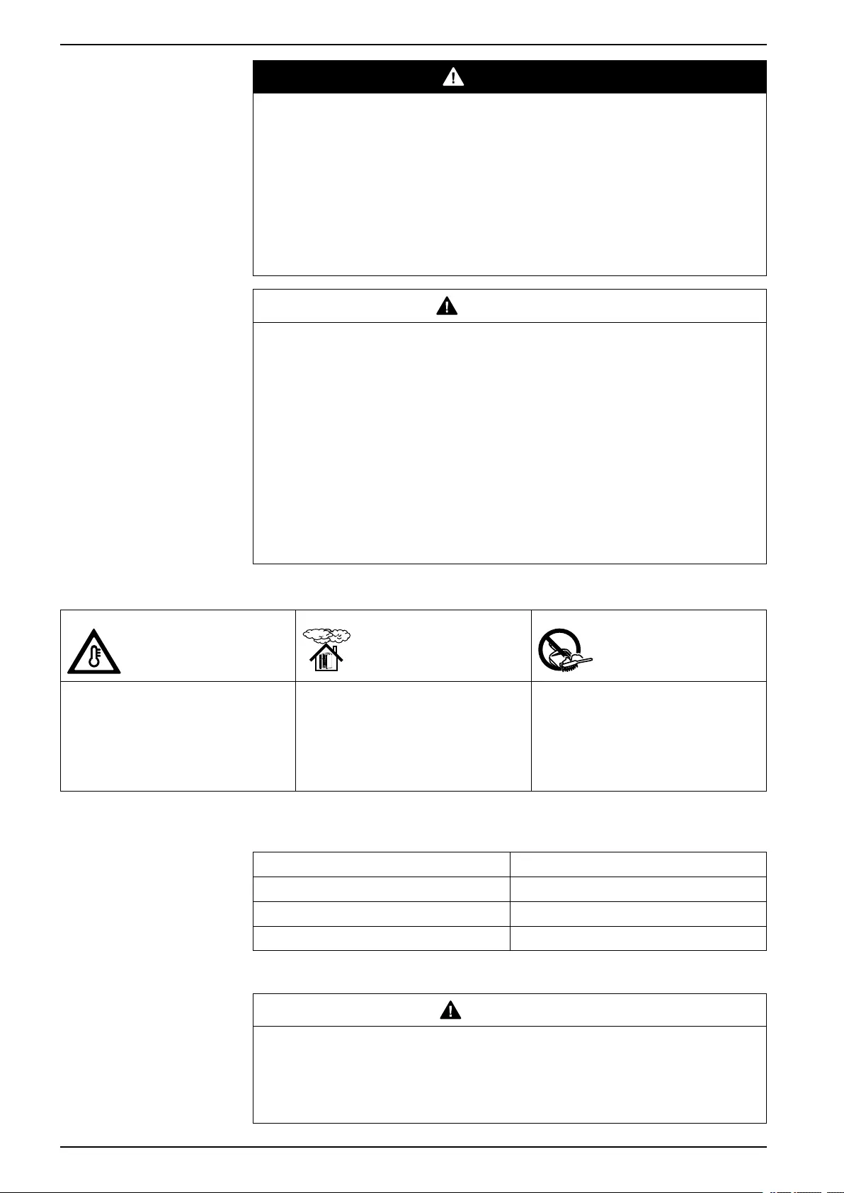
Storage of The Modular Battery Modules
Ambient temperature:
-15 to 40 °C (5 to 104 °F)
Relative humidity: 25-85% Non-condensing The modular batteries must be stored with
their protective packaging still in place.
The modular batteries must be stored
indoors in a place free from:
• vibration
• dust
• direct sunlight
• moisture
NOTE: Stored modular batteries must be recharged at regular intervals depending
on the storage temperature:
Storage temperature Recharge interval
-15 to 20 °C (5 to 68 °F) 9 months
20 to 30 °C (68 to 86 °F) 6 months
30 to 40 °C (86 to 104 °F) 3 months
NOTE: Do not store batteries for more than 12 months.
CAUTION
HAZARD OF PERSONAL INJURY
Two persons are required for lifting a battery module.
Failure to follow these instructions can result in injury or equipment
damage.
30 990–3015J-001
Maintenance 48, 96, and 160 kW 400 V 100 kW 208 V
1. Holding the handle, gently lift the modular battery unit and pull it halfway out. A
locking mechanism prevents the modular battery unit from being pulled all the
way out.
2. Release the locking mechanism by lifting the modular battery unit. Pull the
modular battery unit completely out while supporting it.
3. Take the replacement modular battery unit and push it into the system.
NOTE: When replacing modular batteries, always replace both modular
batteries A+B or C+D (see illustration below) as they are connected in pairs.
For four modular batteries in a row it is recommended to replace all four at the
same time to ensure optimal runtime (Example 1). The modular batteries can
also be replaced in twos, but always A+B (Example 2) or C+D (Example 3).
Four modular batteries in a row
Column A Column B Column C Column D
Example 1 –
Recommended
New New New New
Example 2 – Minimum
requirement
New New Old Old
Example 3 – Minimum
requirement
Old Old New New
NOTE: Allow modular batteries a 24-hour recharging period after system
startup/modular battery replacement for modular battery monitoring data to
become fully reliable.
Replace a Power Distribution Module
• Replace the power distribution module with the system shut down:
◦Replace a Power Distribution Module with the System Shut Down, page
32.
• Replace the power distribution without shutting down the system:
◦Single mains systems: Replace a Power Distribution Module in Battery
Operation, page 34.
◦Dual mains systems: Replace a Power Distribution Module with the Static
Switch Disabled, page 37. This procedure is only applicable to dual utility/
mains systems.
990–3015J-001 31
48, 96, and 160 kW 400 V 100 kW 208 V Maintenance
Replace a Power Distribution Module with the System Shut Down
DANGER
HAZARD OF ELECTRIC SHOCK, EXPLOSION, OR ARC FLASH
Electrical equipment must be installed, operated, serviced, and maintained only
by qualified personnel.
Failure to follow these instructions will result in death or serious injury.
CAUTION
RISK OF INJURY OR EQUIPMENT DAMAGE
• Install only Schneider Electric power distribution modules with matching
output voltage.
• Install power distribution modules starting from the bottom of the panel to
avoid cable congestion.
• Save filler plates for future reuse. If a power distribution module is removed, a
filler plate must be installed to cover the open busbar.
• Slot locks (attached together in pairs) must always be installed on all power
distribution module positions in the panel whether filled by a power
distribution module or a filler plate.
• Make sure all breakers on the power distribution modules being installed are
in the OFF (open) position.
Failure to follow these instructions can result in injury or equipment
damage.
1. Shut down the system by following the procedure Perform a Total Power Off,
page 10.
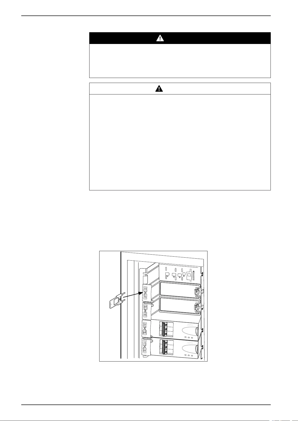
2. Set all breakers on the power distribution module in OFF position.
3. Disconnect the power cable from the power distribution module’s extension
cable or rack-mount PDU.
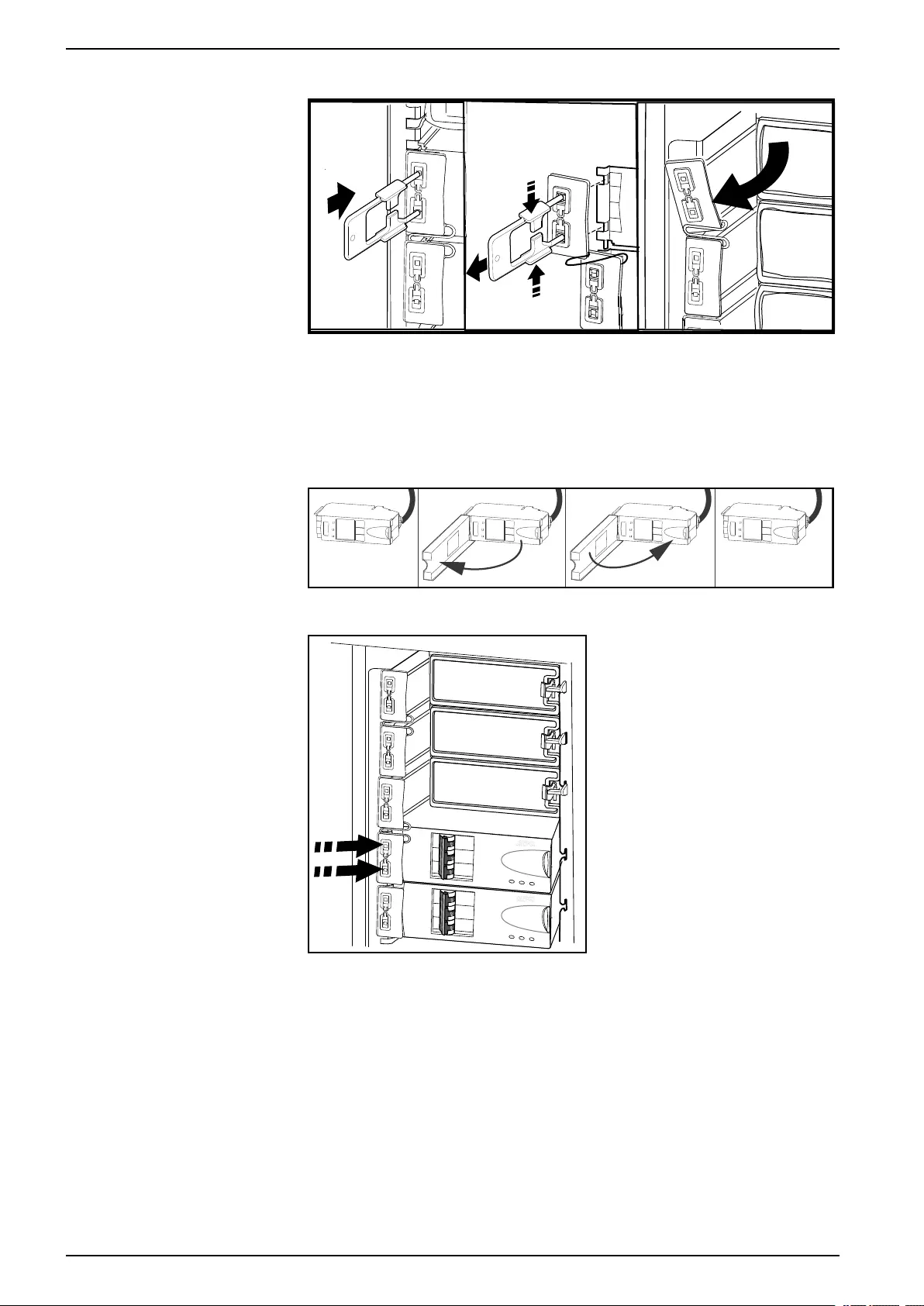
4. Insert the slot key in the slot lock.
5. Squeeze the sides of the key inwards to grasp the slot lock firmly.
32 990–3015J-001
Maintenance 48, 96, and 160 kW 400 V 100 kW 208 V
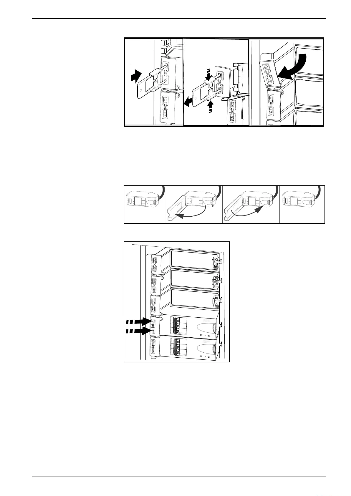
6. Pull the slot key out while squeezing to extract the slot lock from the slot.
7. Open the enable switch on the module and gently pull the module out of the
cabinet.
8. Take the replacement power distribution module and open the enable switch.
Route the power cable through the top of the cabinet and slide the power
distribution module into place.
9. Fasten the latch to lock the module.
10. Install the slot lock by pressing it into the slots.
11. Connect the power distribution module cable to the appropriate equipment.
12. Switch the breakers to the ON position.
13. Start up the system by following the procedure Start the System after Total
Power Off, page 12.
990–3015J-001 33
48, 96, and 160 kW 400 V 100 kW 208 V Maintenance
Replace a Power Distribution Module in Battery Operation
DANGER
HAZARD OF ELECTRIC SHOCK, EXPLOSION, OR ARC FLASH
Electrical equipment must be installed, operated, serviced, and maintained only
by qualified personnel.
Failure to follow these instructions will result in death or serious injury.
CAUTION
RISK OF LOAD DROP
Before replacing a power distribution module with this procedure, verify that:
• The batteries are fully charged and that the UPS runtime displayed on the
UPS status screen is sufficient to support the load during the replacement of
the power distribution module. If sufficient UPS runtime is not available, turn
off all power supplying the equipment and perform appropriate lockout/tagout
procedures before installing or removing the power distribution modules.
Failure to follow these instructions can result in injury or equipment
damage.
CAUTION
RISK OF INJURY OR EQUIPMENT DAMAGE
• Install only Schneider Electric power distribution modules with matching
output voltage.
• Install power distribution modules starting from the bottom of the panel to
avoid cable congestion.
• Save filler plates for future reuse. If a power distribution module is removed, a
filler plate must be installed to cover the open busbar.
• Slot locks (attached together in pairs) must always be installed on all power
distribution module positions in the panel whether filled by a power
distribution module or a filler plate.
• Make sure all breakers on the power distribution modules being installed are
in the OFF (open) position.
Failure to follow these instructions can result in injury or equipment
damage.
1. Unpack the new power distribution module.
2. Open the UPS input breaker (Q1).
Verify that the system is in battery operation. The Load Powered LED on the
display should be lit in yellow. Verify that there are no alarms on the display.
CAUTION
RISK OF LOAD DROP
The remaining steps of this procedure must be completed within the
remaining runtime available.
Failure to follow these instructions can result in injury or equipment
damage.
34 990–3015J-001
Maintenance 48, 96, and 160 kW 400 V 100 kW 208 V
3. If the UPS has dual mains supply, open the bypass input breaker Q5 (if
available). If the UPS does not have a Q5 breaker, turn the enable switch of
the static switch module to the left to the unlocked position to disable the static
switch module.
4. Set all breakers on the power distribution module in OFF position.
5. Disconnect the power cable from the power distribution module’s extension
cable or rack-mount PDU.
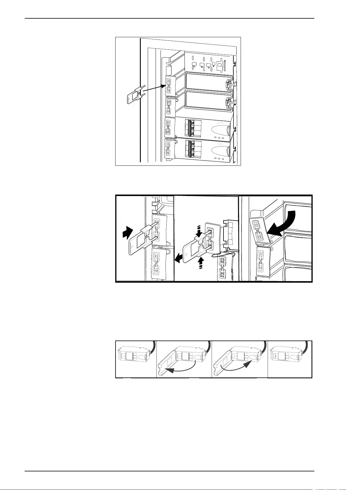
6. Insert the slot key in the slot lock.
7. Squeeze the sides of the key inwards to grasp the slot lock firmly.
990–3015J-001 35
48, 96, and 160 kW 400 V 100 kW 208 V Maintenance
8. Pull the slot key out while squeezing to extract the slot lock from the slot.
9. Open the enable switch on the module and gently pull the module out of the
cabinet.
10. Take the replacement power distribution module and open the enable switch.
Route the power cable through the top of the cabinet and slide the power
distribution module into place.
11. Fasten the latch to lock the module.
12. Install the slot lock by pressing it into the slots.
13. Connect the power distribution module cable to the appropriate equipment.
14. Switch the breakers to the ON position.
15. If the UPS has dual mains supply, close the bypass input breaker Q5 (if
available). If the system does not have a Q5 breaker, turn the enable switch of
the static switch module to the right to enable the static switch module.
16. Close the UPS input breaker Q1.
17. Verify that the UPS Mode is Normal Operation. The Load Powered LED on
the display should be lit green.
36 990–3015J-001
Maintenance 48, 96, and 160 kW 400 V 100 kW 208 V
Replace a Power Distribution Module with the Static Switch Disabled
DANGER
HAZARD OF ELECTRIC SHOCK, EXPLOSION, OR ARC FLASH
Electrical equipment must be installed, operated, serviced, and maintained only
by qualified personnel.
Failure to follow these instructions will result in death or serious injury.
CAUTION
RISK OF INJURY OR EQUIPMENT DAMAGE
• Install only Schneider Electric power distribution modules with matching
output voltage.
• Install power distribution modules starting from the bottom of the panel to
avoid cable congestion.
• Save filler plates for future reuse. If a power distribution module is removed, a
filler plate must be installed to cover the open busbar.
• Slot locks (attached together in pairs) must always be installed on all power
distribution module positions in the panel whether filled by a power
distribution module or a filler plate.
• Make sure all breakers on the power distribution modules being installed are
in the OFF (open) position.
Failure to follow these instructions can result in injury or equipment
damage.
NOTE: This procedure is only applicable to dual utility/mains systems.
1. Open the bypass input breaker Q5 (if available). If the UPS does not have a
Q5 breaker, turn the enable switch of the static switch module to the left to the
unlocked position to disable the static switch module.
2. Set all breakers on the power distribution module in OFF position.
3. Disconnect the power cable from the power distribution module’s extension
cable or rack-mount PDU.
990–3015J-001 37
48, 96, and 160 kW 400 V 100 kW 208 V Maintenance
4. Insert the slot key in the slot lock.
5. Squeeze the sides of the key inwards to grasp the slot lock firmly.
6. Pull the slot key out while squeezing to extract the slot lock from the slot.
7. Open the enable switch on the module and gently pull the module out of the
cabinet.
8. Take the replacement power distribution module and open the enable switch.
Route the power cable through the top of the cabinet and slide the power
distribution module into place.
9. Fasten the latch to lock the module.
38 990–3015J-001
Maintenance 48, 96, and 160 kW 400 V 100 kW 208 V
10. Install the slot lock by pressing it into the slots.
11. Connect the power distribution module cable to the appropriate equipment.
12. Switch the breakers to the ON position.
13. Close the bypass input breaker Q5 (if available). If the system does not have a
Q5 breaker, turn the enable switch of the static switch module to the right to
enable the static switch module.
990–3015J-001 39

48, 96, and 160 kW 400 V 100 kW 208 V Troubleshooting
Troubleshooting
DANGER
HAZARD OF ELECTRICAL SHOCK, EXPLOSION OR ARC FLASH
Only trained personal familiar with the construction and operation of the
equipment, as well as the electrical and mechanical hazards involved, may
install and remove system components.
Failure to follow these instructions will result in death or serious injury.
Status and Alarm Messages
This section lists the status and alarm messages that the UPS might display. The
messages are listed in alphabetical order, and a suggested corrective action is
listed with each alarm message to help you troubleshoot problems.
NOTE: Contact Schneider Electric Customer Support if you see alarm or status
messages that are not listed here.
NOTE: If a problem is reported, ensure that the system component in question is
correctly installed.
Display Messages
Display Message Meaning Corrective Action
Battery Alarm A battery module has become inoperable
and requires replacement.
Replace battery. See Replace a Modular
Battery in a Modular Battery Cabinet, page
29 or contact Schneider Electric Customer
Support for replacement of a classic battery.
Battery Charger Alarm The battery charger is not functioning
properly.
Contact Schneider Electric Customer
Support.
Battery High Temperature Alarm The temperature of one or more battery
units has exceeded system specifications.
Ensure that the ambient temperature meets
the specifications of the system. If the
ambient temperature is below 40 °C (104 °
F), then initiate a self-test to detect any
damaged battery units. Replace any
damaged battery units.
Battery High Voltage Alarm The battery voltage is too high and the
charger has been deactivated.
Contact Schneider Electric Customer
Support.
Battery Monitor Card Alarm The battery monitor card has become
inoperable.
Contact Schneider Electric Customer
Support.
Battery Monitor Card Removed The battery monitor card has been removed. Contact Schneider Electric Customer
Support.
Contact Schneider Electric For Secure
Start-Up
The UPS has been running 5 days. Start-up
check by a Schneider Electric Field Service
Engineer (FSE) is recommended.
Contact Schneider Electric Customer
Support.
Discharged Battery The UPS is online and the battery charge is
low.
No corrective action necessary. Note: If the
input voltage becomes unavailable, runtime
will be limited.
Extended Run Frame Alarm One of the battery cabinets has become
inoperable.
Contact Schneider Electric Customer
Support.
External DC Disconnect Switch Open The external DC DISCONNECT switch
tripped. Battery power is not available or the
runtime is lower than expected.
Close the external DC DISCONNECT
switch. If the problem continues, call
Schneider ElectricCustomer Support.
External Switch Gear Communication
Card Alarm
The external switch gear communication
card has become inoperable.
Contact Schneider Electric Customer
Support.
External Switch Gear Communication
Card Removed
The system no longer detects an external
switch gear communication card.
Option 1: Ensure the external switch gear
communication card is installed properly.
40 990–3015J-001

Troubleshooting 48, 96, and 160 kW 400 V 100 kW 208 V
Display Message Meaning Corrective Action
Option 2: Contact Schneider Electric
Customer Support.
Graceful Shutdown Initiated A graceful shutdown or reboot has been
initiated from the display interface or other
accessory.
No corrective action necessary.
In Bypass: Hardware Not Fully
Functional
The system has transferred into bypass
because an event has occurred.
Contact Schneider Electric Customer
Support.
In Bypass: Overload The system has transferred into bypass
because the load has exceeded the power
capacity of the system.
Option 1: Decrease the load.
Option 2: Add a power module to the
system.
In Bypass: User-Initiated The system has been transferred into
bypass due to user action.
Check for any abnormalities with the
system.
Transfer the system to normal operation.
Internal Communication Bus Alarm One of the buses used for communication
between the UPS modules has become
inoperable.
Contact Schneider Electric Customer
Support.
Input Voltage or Frequency Cannot
Support Bypass
The frequency or voltage is out of
acceptable range for bypass. This message
occurs when the UPS is online, and
indicates that bypass mode may not be
available if required.
Correct the input voltage to provide
acceptable voltage or frequency.
Inverter Not Synchronized To AC Input System cannot synchronize to AC line and
bypass mode may not be available.
Option 1: Decrease the sensitivity to input
frequency.
Option 2: Correct the input voltage to
provide acceptable voltage/frequency.
Load (kVA) Alarm The load has exceeded the user specified
load alarm threshold.
Option 1: Use the display interface to raise
the alarm threshold.
Option 2: Reduce the load.
Local Management-To-UPS
Communication Lost
Internal communications in the system is no
longer available.
Contact Schneider Electric Customer
Support.
Loss Of Battery Capacity (Lower Than
50%)
The battery capacity is estimated to be
below 50% of the expected.
Replace battery. See Replace a Modular
Battery in a Modular Battery Cabinet, page
29 or contact Schneider Electric Customer
Support for replacement of a classic battery.
Loss Of Battery Capacity (Lower Than
75%)
The battery capacity is estimated to be
below 75% of the expected.
Replace battery. See Replace a Modular
Battery in a Modular Battery Cabinet, page
29 or contact Schneider Electric Customer
Support for replacement of a classic battery.
Low Battery The UPS is in battery operation and the
battery charge is low.
Runtime is limited. Shut down the system
and the load equipment or restore the input
voltage.
Main Intelligence Module Alarm The main intelligence module has become
inoperable and requires replacement.
Contact Schneider Electric Customer
Support.
No Batteries Detected No battery power is available. Option 1: Ensure the batteries are installed
properly.
Option 2: Check to see whether the DC
Breaker has been tripped.
Option 3: Contact Schneider Electric
Customer Support.
No Power Modules Detected No power modules are available. Option 1: Ensure that the power modules
are properly installed, the two fastening
screws are tight, and the enable switch is
engaged.
Option 2: Check for other communication
alarm messages in the log.
Overload On UPS The load has exceeded the system power
capacity.
Option 1: Decrease the load.
Option 2: Add a power module to the
system.
Power Module Alarm A power module has become inoperable
and requires replacement.
Replace power module. See
Replace a Power Module with System in
Maintenance Bypass Operation, page 25.
990–3015J-001 41

48, 96, and 160 kW 400 V 100 kW 208 V Troubleshooting
Display Message Meaning Corrective Action
Power Outage The input voltage is not acceptable for
normal operation.
Contact Schneider Electric Customer
Support.
Redundancy Alarm Actual power module redundancy has fallen
below user-specified redundancy alarm
threshold. At least one power module has
become inoperable, or the load has
increased.
Option 1: If possible, install additional
power modules. See
Replace a Power Module with System in
Maintenance Bypass Operation, page 25.
Option 2: Replace inoperable modules. See
Replace a Power Module with System in
Maintenance Bypass Operation, page 25.
Option 3: Reduce the load.
Option 4: Change alarm limit.
Redundancy Lost The UPS no longer detects redundant
power modules. One or more power
modules have become inoperable, or the
load has increased.
Option 1: If possible, install additional
power modules. See
Replace a Power Module with System in
Maintenance Bypass Operation, page 25.
Option 2: Replace inoperable modules. See
Replace a Power Module with System in
Maintenance Bypass Operation, page 25.
Option 3: Reduce the load.
Option 4: Change alarm limit.
Redundant Intelligence Module Alarm The redundant intelligence module has
become inoperable and requires
replacement.
Contact Schneider Electric Customer
Support.
Redundant Intelligence Module in
Control
The main intelligence module has become
inoperable, and the redundant intelligence
module is functioning as the primary
intelligence module.
Contact Schneider Electric Customer
Support.
Replacement Battery Needed One or more battery packs have been
detected to be inoperable (caused by
symmetry event, fuse blown, over-
temperature event, or wrong battery type).
The UPS display will point out the position of
the batteries you have to replace.
Replace battery unit(s). See
Replace a Modular Battery in a Modular
Battery Cabinet, page 29
or contact Schneider Electric Customer
Support for replacement of a classic battery.
Runtime Alarm The predicted runtime is lower than the
user-specified minimum runtime alarm
threshold. At least one battery module has
become inoperable or the load has
increased.
Option 1: Install additional battery modules.
Option 2: Replace the inoperable battery
modules.
See
Replace a Modular Battery in a Modular
Battery Cabinet, page 29
or contact Schneider Electric Customer
Support for replacement of a classic battery.
Option 3: Reduce the load.
Option 4: Change alarm limit.
Site Wiring Incorrect There is a problem with the phase rotation
or a phase is missing in the input voltage to
the UPS, or the neutral is missing.
Contact the certified electrician that installed
the system.
Static Bypass Switch Module Not Fully
Functional
The static bypass switch module has
become inoperable and requires
replacement.
Contact Schneider Electric Customer
Support.
Static Bypass Switch Module Removed The system no longer detects a static
bypass switch module.
Option 1: Ensure that the static bypass
switch module is installed properly.
Option 2: Call Schneider Electric Customer
Support for replacement of the static bypass
switch module.
System in Maintenance Bypass The system is in maintenance bypass: the
Q2 breaker is open and the Q3 breaker is
closed.
No corrective action necessary.
System Power Supply Card Alarm The system power supply card has become
inoperable and requires replacement.
Ensure that the power supply card is
installed properly. See
Replace a Smart Slot Card, page 25.
System Start-Up Configuration Incorrect The system configuration download did not
succeed. Unable to determine the system
voltage or frame size.
Check for other alarms and contact
Schneider Electric Customer Support.
42 990–3015J-001

Troubleshooting 48, 96, and 160 kW 400 V 100 kW 208 V
Display Message Meaning Corrective Action
Technical Check Recommended Regular maintenance requirements and the
end of service life consumable components.
Contact Schneider Electric Customer
Support.
Warranty Expiring Soon The end of the contractual legal warranty. Contact Schneider Electric Customer
Support.
Modular Distribution Alarm List
The display interface will identify the number of the power distribution modules that
has caused an alarm or warning.
Display Message Meaning Corrective Action
High Module Current Alarm The threshold of the high module current
has been exceeded.
Evaluate the threshold setting. If necessary,
adjust it for your situation.
High Subfeed Current Alarm The threshold of the high subfeed current
has been exceeded.
Evaluate the threshold setting. If necessary,
adjust it for your situation.
Low Module Current Alarm The threshold of the low module current has
been exceeded.
Evaluate the threshold setting. If necessary,
adjust it for your situation.
Low Subfeed Current Alarm The threshold of the low subfeed current has
been exceeded.
Evaluate the threshold setting. If necessary,
adjust it for your situation.
Max Module Current Alarm The threshold of the maximum module
current has been exceeded.
Evaluate the threshold setting. If necessary,
adjust it for your situation.
Max Subfeed Current Alarm The threshold of the maximum subfeed
current has been exceeded.
Evaluate the threshold setting. If necessary,
adjust it for your situation.
Min Module Current Alarm The threshold of the minimum module
current has been exceeded.
Evaluate the threshold setting. If necessary,
adjust it for your situation.
Min Subfeed Current Alarm The threshold of the minimum subfeed
current has been exceeded.
Evaluate the threshold setting. If necessary,
adjust it for your situation.
Communication Lost With Metering
Board Alarm
Communication has been lost with the
power distribution module.
Check the communication cables to ensure
that they are properly connected. Contact
Schneider Electric Customer Support (see
the back cover).
Module Breaker Open Alarm A modular circuit breaker is open. Check the modular circuit breakers to see if
one has been over-loaded. Replace if
necessary.
Subfeed Breaker Open Alarm A subfeed circuit breaker is open. Check the subfeed circuit breakers to see if
one has been over-loaded.
990–3015J-001 43

48, 96, and 160 kW 400 V 100 kW 208 V Troubleshooting
PDU Alarm List
Display Message Meaning Corrective Action
System In Maintenance Bypass The system is in maintenance bypass: the
Q2 switch is open and the Q3 switch is
closed.
No corrective action necessary.
Min Output Voltage Alarm Phase-to-neutral output voltage for phase
<L-N> has dropped below the configured
limit.
Evaluate the threshold setting. If necessary,
adjust it for your situation.
Max Output Voltage Alarm Phase-to-neutral output voltage for phase
<L-N> exceeded the configured limit.
Evaluate the threshold setting. If necessary,
adjust it for your situation.
Max Total Output Current Alarm Current of output phase <n> exceeded the
configured limit.
Evaluate the threshold setting. If necessary,
adjust it for your situation.
Min Total Output Current Alarm Current of output phase <n> dropped below
the configured limit.
Evaluate the threshold setting. If necessary,
adjust it for your situation.
Output Frequency Alarm Frequency of the output current is above or
below the range that is configured as
acceptable.
Evaluate the threshold setting. If necessary,
adjust it for your situation.
Critical Input Contact Fault A user-configured contact connected to the
system is reporting an alarm condition.
Determine why the alarm has occurred. This
is a user-specific alarm setting.
System Mode Alarm1The Q1 switch is open, and the UPS is
disconnected from the input voltage.
Close the Q1 switch to reconnect the UPS to
utility/mains power.
System Mode Alarm1The Q2 & Q3 switches are open, and the
system is not supporting the connected
equipment.
For safety reasons, ensure that the switches
were not closed for maintenance purposes.
If the switches are open, close Q2 for UPS
operation, and Q3 for maintenance bypass.
System Mode Alarm1The alarm will be active in the event Q3 is
on at the same time as Q1 and Q5.
Option 1: Resume normal UPS operation.
Option 2: Go to maintenance bypass.
Option 3: Contact Schneider Electric
Customer Support.
Transformer Overheating The temperature of the transformer has
exceeded 180 °C.
Option 1: Resume normal UPS operation.
Option 2: Go to maintenance bypass.
Option 3: Contact Schneider Electric
Customer Support.
Cooling Fan Outage Alarm One fan is not working or not spinning fast
enough, or one pole of the 3-pole circuit
breaker has tripped.
Option 1: Make sure all four fans are
running.
Option 2: Check breaker positions.
Option 3: Contact Schneider Electric
Customer Support.
44 990–3015J-001
1. See the event log for further clarification.


Schneider Electric
35 rue Joseph Monier
92500 Rueil Malmaison
France
+ 33 (0) 1 41 29 70 00
www.schneider-electric.com
As standards, specifications, and design change from time to time,
please ask for confirmation of the information given in this publication.
© 2013 – 2017 Schneider Electric. All rights reserved.
990–3015J-001
Одиночная и
параллельная
установка
Symmetra PX
250/500 кВт, 400/480 В
test
Правовая оговорка компании «American Power Conversion»
Корпорация «American Power Conversion» не гарантирует надежность, полноту и
безошибочностьпредставленной в настоящем руководстве информации. Данное
издание не является заменойподробному оперативному плану, разработанному с
учетом конкретных условий монтажа. Таким образом, корпорация «American Power
Conversion» не несет никакой ответственности за ущерб,нарушения законов, неправильно
выполненный монтаж, сбой системы и другие проблемы,которые могут возникнуть в
связи с использованием настоящего издания.
Информация, содержащаяся в настоящем издании, предоставляется в виде «как есть»
исключительно для планирования дизайна и проектирования вычислительного центра.
Информация для данного издания была добросовестно собрана корпорацией «American
PowerConversion». Однако не дается никакой гарантии, выраженной или подразумеваемой,
в отношенииполноты и точности представленной в издании информации.
КОРПОРАЦИЯ AMERICAN POWER CONVERSION, А ТАКЖЕ ЛЮБАЯ
ГОЛОВНАЯИЛИ ДОЧЕРНЯЯ КОМПАНИЯ ИЛИ ФИЛИАЛ КОРПОРАЦИИ
AMERICAN POWER CONVERSION ИЛИ СООТВЕТСТВУЮЩИЕ СЛУЖАЩИЕ,
РУКОВОДИТЕЛИ,СОТРУДНИКИ НЕ НЕСУТ НИКАКОЙ ОТВЕТСТВЕННОСТИ
ЗА ЛЮБЫЕ ПРЯМЫЕ,КОСВЕННЫЕ, ПОБОЧНЫЕ, ШТРАФНЫЕ, ОСОБЫЕ
ИЛИ СЛУЧАЙНЫЕ УБЫТКИ (ВКЛЮЧАЯ, В ТОМ ЧИСЛЕ, УБЫТКИ ИЗ-ЗА
УТРАТЫ ПРЕДПРИЯТИЯ, РАСТОРЖЕНИЯ ДОГОВОРА, ПОТЕРИ ВЫРУЧКИ,
ДАННЫХ, ИНФОРМАЦИИ ИЛИПРЕРЫВАНИЯ ДЕЯТЕЛЬНОСТИ), ВОЗНИКШИЕ
В РЕЗУЛЬТАТЕ ИЛИ В СВЯЗИ СИСПОЛЬЗОВАНИЕМ НАСТОЯЩЕГО ИЗДАНИЯ
ИЛИ НЕСПОСОБНОСТИ ЕГОИСПОЛЬЗОВАТЬ, ДАЖЕ ЕСЛИ КОРПОРАЦИЯ
AMERICAN POWER CONVERSION БЫЛА НЕПОСРЕДСТВЕННО УВЕДОМЛЕНА
О ВОЗМОЖНОСТИ ТАКИХ УБЫТКОВ. КОРПОРАЦИЯ «AMERICAN POWER
CONVERSION» ОСТАВЛЯЕТ ЗА СОБОЙ ПРАВОИЗМЕНЯТЬ ИЛИ ОБНОВЛЯТЬ
СОДЕРЖАНИЕ И ФОРМАТ НАСТОЯЩЕГО ИЗДАНИЯВ ЛЮБОЕ ВРЕМЯ БЕЗ
УВЕДОМЛЕНИЯ.
Авторские, интеллектуальные и иные имущественные права на содержание (включая,
в томчисле, программное обеспечение, звуковые и видеофайлы, текст и фотографии)
настоящегоиздания принадлежат корпорации «American Power Conversion» или ее
лицензиарам. Все права насодержание, не предоставленные явным путем в настоящем
документе, защищены. Никакиеправа не передаются, не отчуждаются и не переходят
лицам, получающим доступ к даннойинформации.
Настоящее издание целиком или любая его часть не подлежит перепродаже.
iv
Symmetra PX250/500 кВт, 400/480 В Одиночная и параллельная установка 990–2748F-028
Условные обозначения
Предупреждение: Указывает на опасность поражения электрическим током,
которая может привести к травме или смерти.
Внимание: Указывает на опасность, которая может привести к травме или смерти.
Примечание: Указывает на важную информацию.
990–2748F-028
Symmetra PX250/500 кВт, 400/480 В Одиночная и параллельная установка
1
Общие сведения о системе
Система с подбором и сопряжением батарей
Система с MBwD
A. MBwD
B. Шкаф входа/выхода/байпаса
C. Шкаф силового модуля
D. Батарейный шкаф
Система без MBwD
A. Шкаф входа/выхода/байпаса
B. Шкаф силового модуля
C. Батарейный шкаф
Система с удаленными батареями
Система с MBwD
A. MBwD
B. Шкаф входа/выхода/байпаса
C. Шкаф силового модуля
D. Шкафы с батареями
E. Боковой шкаф с батареями
Система без MBwD
A. Шкаф входа/выхода/байпаса
B. Шкаф силового модуля
C. Шкафы с батареями
D. Боковой шкаф с батареями
2
Symmetra PX250/500 кВт, 400/480 В Одиночная и параллельная установка
990–2748F-028
Общие сведения об автоматических выключателях
в MBwD (дополнительно)
Примечание: MBwD применяется только для одиночных систем.
APC MBwD содержит автоматические
включатели Q2, Q3 и Q5. Если индикатор
автоматического выключателя горит, значит
данный выключатель можно размыкать и
замыкать.
To Distribution Breakers
Обзор дисплея
Примечание: В данном руководстве экраны представлены только в качестве
примеров.
Графический интерфейс пользователя ИБП
встроен в шкаф входа/выхода/байпаса.
Сенсорный экран ИБП используется для
настройки и мониторинга системы, а также
для подачи визуальных и звуковых сигналов
пользователю.
Экраны представлены в иерархическом
порядке. В параллельных системах на верхнем
уровне находится экран «Parallel System
Summary» (Информация о параллельной
системе). В одиночных системах на верхнем
уровне находится экран «UPS Summary»
(Информация об ИБП).
990–2748F-028
Symmetra PX250/500 кВт, 400/480 В Одиночная и параллельная установка
3
Навигация
Система ИБП
Информация о системе
Состояние системы
Журналы
Общие сведения о
микропрограмме
Профилактическое обслуживание
Лицензии на программное
обеспечение
Configuration (Конфигурация)
Конфигурация пользователя
Служебная конфигурация
Factory Configuration
(Конфигурация изготовителя)
Эксплуатация
Start-Up (Запуск)
Shutdown (Выключение)
Transfer to normal operation
(Переход в обычный режим
работы)
Transfer to static bypass (Переход в
режим статического байпаса)
Изолирование данного ИБП
Включить режим ECO
Языковые настройки
Региональные настройки
Сведения/журнал состояния
модуля
4
Symmetra PX250/500 кВт, 400/480 В Одиночная и параллельная установка
990–2748F-028
Нажмите на кнопку для помощи
APC Symmetra PX
250/500 kW 400/480 V
Single and Parallel Operation
10/2016
www.schneider-electric.com
Manual
View the manual for the APC Symmetra PX here, for free. This manual comes under the category uninterruptible power supplies (UPSs) and has been rated by 3 people with an average of a 8.2.
This manual is available in the following languages: English. Do you have a question about the APC Symmetra PX or do you need help?
Ask your question here
Index
- Important Safety Instructions — SAVE THESE INSTRUCTIONS
- System Overview
- Configuration
- Operation Modes
- Operation Procedures
- Maintenance
- Troubleshooting
- Blank Page
- Blank Page
Product Images (3)

APC Symmetra PX specifications
Below you will find the product specifications and the manual specifications of the APC Symmetra PX.
The APC Symmetra PX is an uninterruptible power supply (UPS) with an output power capacity of 32 kVA, capable of delivering 32000 W of power. It features an Emergency Power Off (EPO) function, allowing for quick and safe shutdown in case of emergencies. The UPS utilizes VRLA (Valve-Regulated Lead Acid) batteries, which are known for their maintenance-free operation and long service life. The batteries are hot-swappable, ensuring continuous power supply without interruption during battery replacement.
With dimensions of 1200 x 1070 x 1991 mm and a weight of 1095400 g, the APC Symmetra PX is designed to be installed in a rack or a dedicated space. The unit operates at a noise level of 61 dB, emitting an audible alarm when a power issue occurs. The battery recharge time is relatively fast, taking only 3.5 hours to fully recharge.
For transportation purposes, the UPS comes packaged in dimensions of 1696 x 1210 x 2140 mm and weighs 1189000 g. This ensures proper protection and easy handling during shipping.
Overall, the APC Symmetra PX is a reliable and durable UPS that provides a high output power capacity and includes essential features for maintaining a continuous power supply. Its VRLA battery technology ensures long-lasting performance, while the hot-swappable design allows for seamless battery replacement. With its compact design and audible alarm system, the APC Symmetra PX is a suitable choice for various applications that require a robust UPS solution.
Output power capacity
32 kVA
Output connections
1 x Hard Wire 5-wire (3PH + N + G)
Features
| Output power capacity | 32 kVA |
| Output power | 32000 W |
| Emergency Power Off (EPO) | Yes |
| Noise level | 61 dB |
| Audible alarm(s) | Yes |
Other features
| Output connections | 1 x Hard Wire 5-wire (3PH + N + G) |
| Battery type | VRLA |
| Dimensions (WxDxH) | 1200 x 1070 x 1991 mm |
| Package dimensions (WxDxH) | 1696 x 1210 x 2140 mm |
Battery
| Hot-swap battery | Yes |
| Battery technology | Sealed Lead Acid (VRLA) |
| Battery recharge time | 3.5 h |
Design
| Product color | Black |
| LED indicators | Yes |
Weight & dimensions
Packaging data
Operational conditions
| Operating temperature (T-T) | 0 — 40 °C |
| Operating relative humidity (H-H) | 0 — 95 % |
| Operating altitude | 0 — 999.9 m |
| Storage temperature (T-T) | -15 — 40 °C |
| Storage relative humidity (H-H) | 0 — 95 % |
| Non-operating altitude | 0 — 15000 m |
Certificates
| Certification | EN 50091-1, EN/IEC 62040-3, EN/IEC 62040-1-1, FCC Part 15 Class A, VFI-SS-111 |
show more
Frequently Asked Questions
Can’t find the answer to your question in the manual? You may find the answer to your question in the FAQs about the APC Symmetra PX below.
Why is the input voltage range important for the UPS APC Symmetra PX?
Ensuring the input voltage remains within the range specified by the UPS is crucial for optimal performance and protection against power fluctuations or surges. It helps prevent potential damage to connected devices.
How can I determine the maximum load I can connect to the UPS APC Symmetra PX?
To calculate the maximum load, you need to consider the UPS’s capacity, represented in VA (volt-amps) or Watts. Sum up the power ratings of all devices you plan to connect, ensuring it does not exceed the UPS’s capacity.
What is the difference between runtime and battery backup time?
Runtime refers to the duration the UPS can power your connected devices during a power outage, while battery backup time specifically indicates how long the UPS can sustain power to your equipment given the current load. It’s essential to consider both factors when assessing your power needs.
How do I perform a self-test on the UPS APC Symmetra PX?
To execute a self-test, locate the self-test button on the front panel of the UPS and press it. This will initiate a test to ensure proper functionality of the UPS and its battery. The results will be indicated through audible alarms or LED indicators.
Why is it important to monitor and manage the UPS APC Symmetra PX?
Monitoring and managing the UPS allows you to proactively identify any potential issues and ensure the system is operating optimally. It provides valuable insights into power consumption, battery status, and system health, enabling you to take preventive measures and minimize downtime in case of emergencies.
Does the APC Symmetra PX have an output power capacity of 32 kVA?
Yes, the APC Symmetra PX has an output power capacity of 32 kVA. This is a high power capacity, providing ample electricity for devices connected to the UPS.
Can the APC Symmetra PX batteries be hot-swapped?
Yes, the APC Symmetra PX has hot-swap batteries. This means that the batteries can be replaced while the UPS is running, without the need to power down or interrupt connected devices.
What is the battery technology used in the APC Symmetra PX?
The APC Symmetra PX uses Sealed Lead Acid (VRLA) batteries. This technology provides reliable and maintenance-free operation, making it convenient for users.
What are the dimensions of the APC Symmetra PX?
The dimensions of the APC Symmetra PX are 1200 x 1070 x 1991 mm. It is a relatively large UPS, so users should consider the available space for installation.
Does the APC Symmetra PX have audible alarms?
Yes, the APC Symmetra PX features audible alarms. These alarms provide alerts to the user in case of power issues or UPS malfunctions, ensuring prompt attention and action.
What is the weight of the APC Symmetra PX?
The APC Symmetra PX has a weight of 1095400 g.
What certifications does the APC Symmetra PX have?
The APC Symmetra PX has the following certifications: EN 50091-1, EN/IEC 62040-3, EN/IEC 62040-1-1, FCC Part 15 Class A, VFI-SS-111.
How long does it take to charge the battery of the APC Symmetra PX?
It takes 3.5 h to charge the battery of the APC Symmetra PX.
Is the manual of the APC Symmetra PX available in English?
Yes, the manual of the APC Symmetra PX is available in English .
Is your question not listed? Ask your question here
User manual
View the manual for the APC Symmetra PX here, for free. This manual comes under the category uninterruptible power supplies (UPSs) and has been rated by 3 people with an average of a 8.2. This manual is available in the following languages: English. Do you have a question about the APC Symmetra PX or do you need help?
Ask your question here
Frequently Asked Questions
Can’t find the answer to your question in the manual? You may find the answer to your question in the FAQs about the APC Symmetra PX below.
What is the weight of the APC Symmetra PX?
The APC Symmetra PX has a weight of 1095400 g.
What certifications does the APC Symmetra PX have?
The APC Symmetra PX has the following certifications: EN 50091-1, EN/IEC 62040-3, EN/IEC 62040-1-1, FCC Part 15 Class A, VFI-SS-111.
How long does it take to charge the battery of the APC Symmetra PX?
It takes 3.5 h to charge the battery of the APC Symmetra PX.
Is the manual of the APC Symmetra PX available in English?
Yes, the manual of the APC Symmetra PX is available in English .
Is your question not listed? Ask your question here