
Table of Contents
- OverView
- Dimensions
- Package
- FC & ESC Connection
- F405 V3 Flight Controller
- App & FC Configuration
- FC Firmware Update
- Specifications
- Part 3 – SpeedyBee BLS 50A 4-in-1 ESC
- Specifications
- References
- Read User Manual Online (PDF format)
- Download This Manual (PDF format)
Stack F405 V3
30×30 BLS 50A
F405 V3 BLS 50A 30×30 Stack
User Manual V1.0
OverView
Specs Overview
| Product Name | SpeedyBee F405 V3 BLS 50A 30×30 Stack |
|---|---|
| Right Controller | SpeedyBee F405 V3 |
| ESC | SpeedyBee BLS 50A 4-in-1 ESC |
| Bluetooth | Supported. For FC & ESC parameter settings |
| Wireless FC Firmware Flashing | NOT Supported |
| Wireless Blackbox Dwonload & Analysis | NOT Supported |
| Power Input | 3-65 LiPo |
| Mounting | 30.5 x 30.5mm (4mm hole size ) |
| Dimension | 45.6mm(L) x 44mm(W) x 18.3mm(H) |
| Weight | 23.4g |
Dimensions

Package
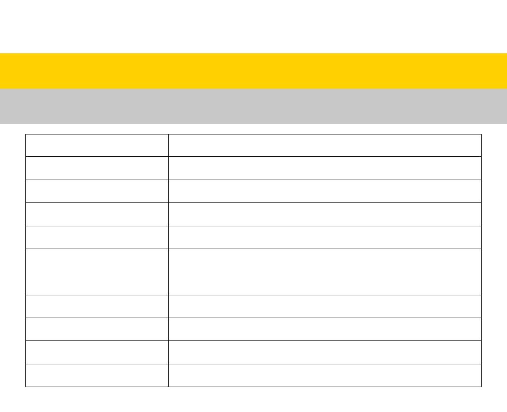
Option 1 – SpeedyBee F405 V3 50A 30×30 Stack

- SpeedyBee F405 V3 Flight Controller x 1
- SpeedyBee BLS 50A 4-in-1 ESC x 1
- 35V 1000uF Low ESR Capacitor x 1
- M3 Nylon Nut x 5
- M3 silicone O Ring x 5
- M3*8mm Silicone Grommets(for FC) x 5
- M3*8.1mm Silicone Grommets(for ESC) x 5
- SH 1.0mm 15mm-length 8pin Cable(for FC-ESC connection) x 1
- M3*30mm Iner-hexagon Screws x 5
- DJI 6pin Cable(80mm) x 1
- XT60 Power Cable(70mm) x 1
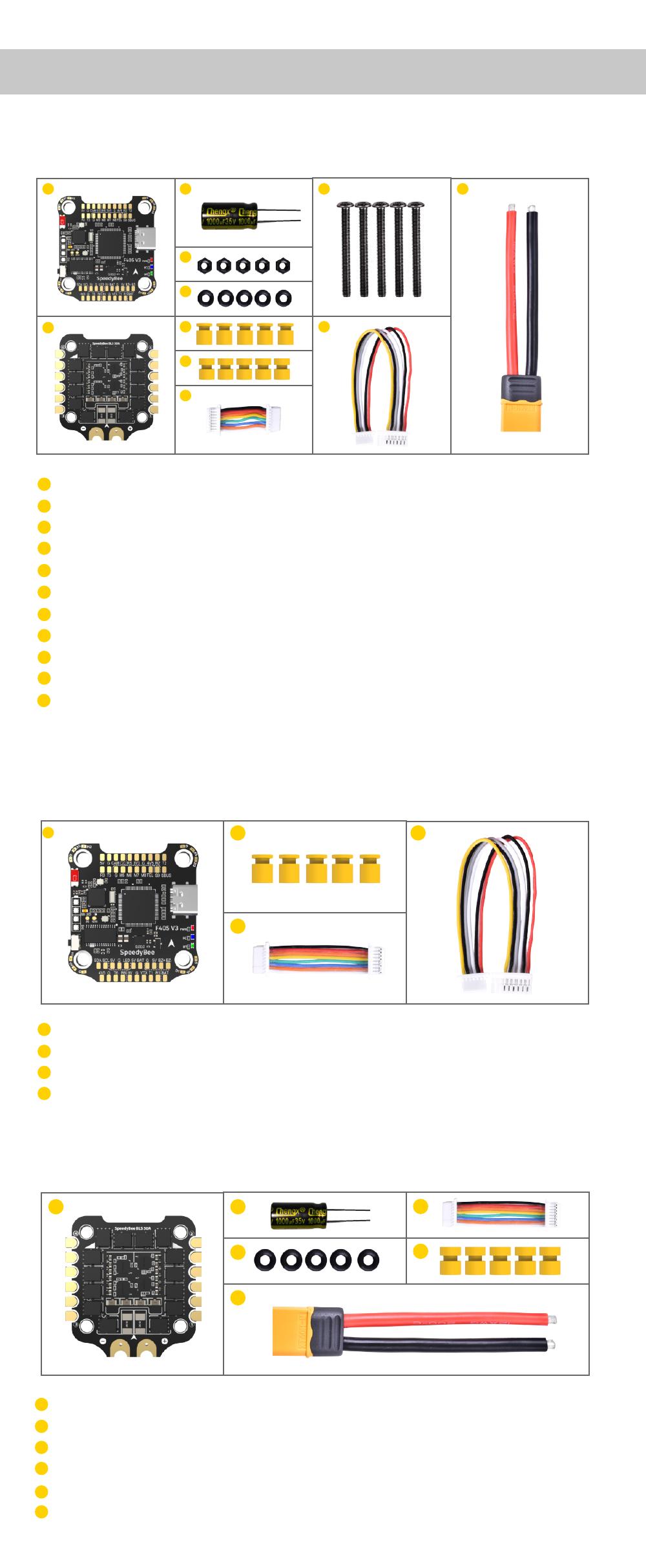
Option 2 – SpeedyBee F405 V3 Flight Controller

- SpeedyBee F405 V3 Flight Controller x 1
- M3*8mm Silicone Grommets(for FC) x 5
- SH 1.0mm 30mm-length 8pin Cable(for FC-ESC connection) x 1
- DJI 6pin Cable(80mm) x 1

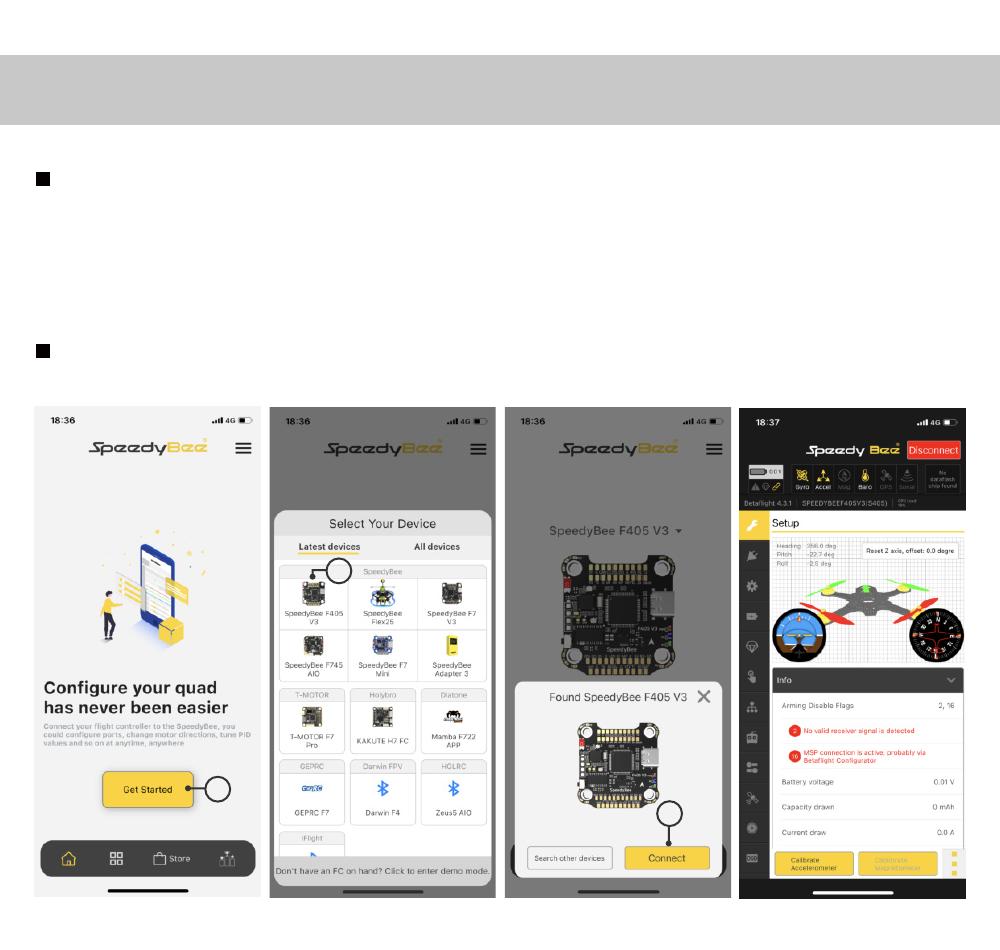
- SpeedyBee BLS 50A 4-in-1 ESC x 1
- 35V 1000uF Low ESR Capacitor x 1
- M3 silicone O Ring x 5
- XT60 Power Cable(70mm) x 1
- SH 1.0mm 30mm-length 8pin Cable(for FC-ESC connection) x 1
- M3*8.1mm Silicone Grommets(for ESC) x 5
FC & ESC Connection
Use the 8-pin cable in the package to connect the FC and the ESC.
Or solder 8 wires directly to the 8 pads on each end.
Method 1 – Using 8-pin cable
Use any end of the 8-pin JST cable to connect the FC to the ESC.

Method 2 – Direct soldering
Solder 8 wires to the 8 pads on each end referring to the pad definition
below.

F405 V3 Flight Controller
Layout


LED Indicator Definition
RED LED – Power Indicator.Solid Red after powering up.
GREEN LED – Bluetooth status light. Solid Green indicates Bluetooth is
connected.
BLUE LED – Flight controller status light which is controlled by the
flight controller firmware.
Long press the button for 3 seconds to switch the control modes between BF_LED
mode and SB_LED mode.
Orange LED – LED Control Mode Indicator. It indicates the 4 sets of LED
strips connected to LED1-LED4 pads on the corners of the flight controller are
controlled by Betaflight firmware(BF_LED mode) or the Bluetooth chip(SB_LED
mode).
Solid Orange :tindicates the 4 x LEDs are in SB_LED mode. In this mode,
when the FC is powered on and in standby mode, press the BOOT button to cycle
the display modes of the LEDs. You could also change modes in the app
wirelessly.
OFF :indicates the 4 x LEDs are controlled by Betaflight firmware.
BOOT Button
[A]Only if the flight controller gets bricked and can’t power up, please
follow these steps to re-flash firmware for it:
- Insert a USB A to TYPE-C cable to your PC.
- Press and hold the BOOT button, insert the USB cable into the flight controller, then release the BOOT button.
- Open Betaflight/Emuflight/INAV configurator on the PC, go to the ‘Firmware Flashing’ page, choose the target ‘SPEEDYBEEF405V3’ and flash.
[B]. When the FC is powered on and in standby mode, the BOOT button can be
used to controller the LED strips connected to LED1-LED4 pads on the corners.
By default, short-press the BOOT button to cycle the LED displaying mode.
Long-press the BOOT button to switch between SpeedyBee-LED mode and BF-LED
mode. Under BF-LED mode, all the LED1-LED4 strips will be controlled by the
Betaflight firmware.
FC’s Peripheral Connection

Note: When using both a receiver and an Air Unit (including a direct
connection using a ribbon cable) on the F405 V3 flight controller, there is an
issue. This arises because the built-in SBUS receiver on the Air Unit and the
external receiver are both connected to the Rx2 pad(SBUS pad) on the flight
controller. As a result, the external receiver cannot be recognized properly
by the flight controller. To resolve this, it is necessary to disconnect the
SBUS wire from the Air Unit or connect the external receiver to the Rx3 pad on
the UART3 port. It is known that SBUS receivers and part of the ELRS receivers
conflict with the built-in receiver on the Air Unit in the F405 V3 flight
controller.Even ELRS reciver has this issue, but TBS reciver will not affected
by this issue.
App & FC Configuration
Get the SpeedyBee App
Search ‘SpeedyBee’ on Google Play or App Store. Or download the Android .apk
file on our website: https://www.speedybee.com/download.
FC Configuration

FC Firmware Update
SpeedyBee F405 V3 flight controller does not support wireless firmware
flashing, so please flash firmware for it on your PC following the steps
below:
- Connect the flight controller to the PC with a USB cable
- Open Betafight/ INAV configurator on your PC. Take Betaflight configurator as an example, go to the ‘Firmware Flashing’ page, choose the target ‘SPEEDYBEEF405V3’ and flash.

Specifications
| Product Name | SpeedyBee F405 V3 30×30 Flight Controller |
|---|---|
| MCU | STM32F405 |
| IMU(Gyro) | BMI270 |
| USB Port Type | Type-C |
| Barometer | Built-in |
| OSD Chip | AT7456E chip |
| BLE Bluetooth | Supported. Used for Flight Controller configuration (MSP should |
be enabled with Baud rate 115200 on UART4)
WIFI| Not supported
WI Air Unit Connection Way| Two ways supported: 6-pin connector or direct
soldering.
6-pin DJI Air Unit Plug| Supported. Completely compatible with DJI O3/RunCam
Link/Caddx Vista/DJI Air Unit V1, no wire is needed to be changed.
Blackbox MicroSD Card Slot| *Betafilght firmware requires the type of the
microSD card to be either Standard (SDSC) or High capacity (SDHC), so extended
capacity cards (SDXC) are not supported(Many highspeed U3 cards are SDXC).
Also the card MUST be formatted with the FAT16 or FAT32 (recommended)
flesystems. So, you could use any SD card less than 32GB, but the Betalight
can only recognize 4GB maximum. We suggest you use this 3rd party formatting
tool and choose ‘Overwrite format then format your card. Also check out bra
for the recommended SD cards or buy the lasted carrlq from our store.
Current Sensor Input| Supported. For SpeedyBee BLS 50A ESC, please set scale =
386 and Offset = 0.
Power Input| 3S – 6S Upo(Through G, BAT pins/pads from the 8-pin connector or
8-pads on the bottom side)
5V Output| 9 groups of 5V output, four +5V pads and 1 BZ+ pad( used for
Buzzer) on front side, and 4x LED 5V pads. The total current load is 2A
9V Output| 2 groups of 9V output, one +9V pad on front side and other
included in a connector on bottom side. The total current load is 2A.
3.3V Output| Supported. Designed for 3.3V-input receivers. Up to 500mAcurrent
load.
4.5V Output| Supported. Designed for receiver and GPS module even when the FC
is powered through the USB port. Up to 1A current load.
ESC Signal| M1 – M4 on bottom side and M5-M13 on front side.
UART| 6 sets(UART1, UART2, UART3, UART4(Dedicated for Bluetooth connection)),
UART5(Dedicated for ESC telemetry),UART6
ESC Telemetry| UART R5(UART5)
12C| Supported. SDA& SCL pads on front side. Used for magnetometer, sonar,
etc.
Traditional Betaflight LED Pad| Supported. 5V, G and LED pads on bottom of the
front side. Used for WS2812 LED controlled by Betafilght firmware.
Buzzer| BZ+ and BZ- pad used for 5V Buzzer
BOOT Button| Supported. [Al Press and hold BOOT button and power the FC on at
the same time will force the FC to enter DFU mode, this is for firmware
flashing when the FC gets bricked. [B]. When the FC is powered on and in
standby mode, the BOOT button can be used to controller the LED strips
connected to LED1-LED4 connectors on the bottom side. By default, short-press
the BOOT button to cycle the LED displaying mode. Long-press the BOOT button
to switch between SpeedyBee-LED mode and BF-LED mode. Under BF-LED mode, all
the LED1-LED4 strips will be controlled by Betaflight firmware.
RSSI Input| Supported. Named as RS on the front side.
Smart Port / F.Port| Not supported
Supported Flight Controller Firmware| BetaFlight(Default), INAV (INAV firmware
can only use Multishot (recommended) and OneShot125. Please note that DShot is
not supported.)
Firmware Target Name| SPEEDYBEEF405V3
Mounting| 30.5 x 30.5mm( 4mm hole diameter)
Dimension| 41.6(L) x 39.4(W) x 7.8(H)mm
Weight| 9.6g
Part 3 – SpeedyBee BLS 50A 4-in-1 ESC
Layout

Connection with Motors & Power Cable

Note: In order to prevent the stack from being burnt out by voltage
spikes on powering up, it is strongly recommended to use the Low ESR capacitor
in the package.
ESC Configuration

If you’d like to use a PC configurator, we recommend the ESC Configurator.
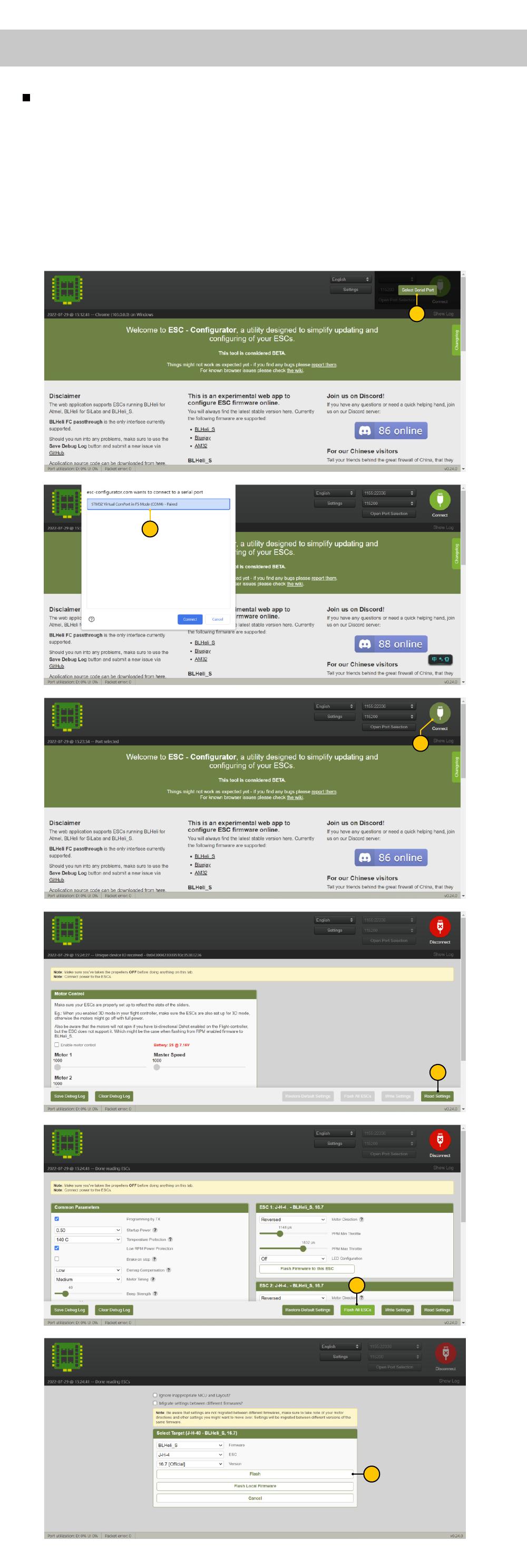
ESC Firmware Update
You could flash both BLHeli_S and Blue Jay firmware for this ESC.
You need to pulg in the battery to the F405 V3 and then connect a USB cable
between the F405 V3 and your PC. Then flash ESC firmware (BLHeli_S or Blue
Jay) in the following online configurator: https://esc-configurator.com/
Note: ESC Type should be set as ‘J-H-50’.


Specifications
| Product Name | SpeedyBee BLS 50A 30×30 4-in-1 ESC |
|---|---|
| Firmware | BLHel1SJHSO |
| Wireless Configuration | Full Configuration Supported in the SpeedyBee app |
| PC Configurator Download Link | httpsfiesc-configuratanom/ |
| Continuous Current | 50A • 4 |
| Burst Current | 55145S) |
| TVS Protective diode | Yes |
| External Capacitor | 1000uF Low ESR Capacitor(In the package) |
| ESC Protocol | DSHOT300/600 |
| Power Input | 3-6S LiPo |
| Power Output | VBAT |
| Current Sensor | Support (Scalta386 OfseL=0) |
| Mounting | 30.5 x 30.5mm( 4mm hole diameter) |
| Dimension | 45.6(1) • 44(W) • 6.1mm(H) |
| Weight | 13.8g |
References
- ESC Configurator — for Bluejay, BLHeli_S and AM32
- download
Read User Manual Online (PDF format)
Read User Manual Online (PDF format) >>
Download This Manual (PDF format)
Download this manual >>

F405 V3
BLS 50A 30×30
F405 V3 BLS 50A 30×30 Stack
User Manual V1.0
(Click on any section to jump)
Contents
Pa 1 — OverView
Specs Oveiew
Dimensions
Package
FC & ESC Connection
Pa 2 — SpeedyBee F405 V3 Flight Controller
Layout
FC’s Peripheral Connection
App & FC Conguration
FC Firmware Update
Specications
Pa 3 — SpeedyBee BLS 50A 4-in-1 ESC
Layout
Connection with Motors & Power Cable
ESC Conguration
ESC Firmware Update
Specications
2
1
3
4
5
6
7
8
9
10
11
12
13
14
Product Name
Flight Controller
ESC
Bluetooth
Wireless FC Firmware Flashing
Power Input
Mounting
Dimension
Weight
SpeedyBee F405 V3 BLS 50A 30×30 Stack
SpeedyBee F405 V3
SpeedyBee BLS 50A 4-in-1 ESC
Suppoed. For FC & ESC parameter settings
NOT Suppoed
3-6S LiPo
30.5 x 30.5mm(4mm hole size )
45.6mm(L) x 44mm(W) x 18.3mm(H)
23.4g
Pa 1 — OverView
1/14
Specs Oveiew
Wireless Blackbox
Dwonload & Analysis NOT Suppoed
Package 3/14
Option 2 — SpeedyBee F405 V3 Flight Controller
SpeedyBee F405 V3 Flight Controller x 1
SpeedyBee BLS 50A 4-in-1 ESC x 1
35V 1000uF Low ESR Capacitor x 1
M3 Nylon Nut x 5
M3 silicone O Ring x 5
M3*8mm Silicone Grommets(for FC) x 5
M3*8.1mm Silicone Grommets(for ESC) x 5
SH 1.0mm 15mm-length 8pin Cable(for FC-ESC connection) x 1
M3*30mm Iner-hexagon Screws x 5
DJI 6pin Cable(80mm) x 1
XT60 Power Cable(70mm) x 1
1
2
3
4
5
6
7
8
9
10
11
1
2
Option 1 — SpeedyBee F405 V3 50A 30×30 Stack
SpeedyBee BLS 50A 4-in-1 ESC x 1
35V 1000uF Low ESR Capacitor x 1
M3 silicone O Ring x 5
XT60 Power Cable(70mm) x 1
SH 1.0mm 30mm-length 8pin Cable(for FC-ESC connection) x 1
M3*8.1mm Silicone Grommets(for ESC) x 5
1
2
3
4
5
6
Option 3 — SpeedyBee BLS 50A 4-in-1 ESC
3 9 11
4
5
610
7
8
1 2
3
4
6
5
SpeedyBee F405 V3 Flight Controller x 1
M3*8mm Silicone Grommets(for FC) x 5
SH 1.0mm 30mm-length 8pin Cable(for FC-ESC connection) x 1
DJI 6pin Cable(80mm) x 1
1
2
3
4
1
3
2 4

FC & ESC Connection 4/14
Method 1 — Using 8-pin cable
Use the 8-pin cable in the package to connect the FC and the ESC.
Or solder 8 wires directly to the 8 pads on each end.
Use any end of the 8-pin JST cable to connect the FC to the ESC.
Solder 8 wires to the 8 pads on each end referring to the
pad denition below.
Method 2 — Direct soldering
BTA
GND
M2
M3
M4
CUR
TEL
M1
VBTA
GND
S2
S3
S4
CURRENT
N/A
S1
F405 V3 Flight Controller BLS 50A 4-in-1 ESC
BLS 50A 4-in-1 ESC
F7 V3 Flight Controller

Pa 2 — F405 V3 Flight Controller
5/14
Layout
LED Indicator Denition
RED LED — Power Indicator.Solid Red after powering up.
GREEN LED — Bluetooth status light. Solid Green indicates Bluetooth is connected.
BLUE LED — Flight controller status light which is controlled by the ight controller rmware.
[A]Only if the ight controller gets bricked and can’t power up, please follow these
steps to re-ash rmware for it:
① Inse a USB A to TYPE-C cable to your PC.
② Press and hold the BOOT button, inse the USB cable into the ight controller,
then release the BOOT button.
③ Open Betaight/Emuight/INAV congurator on the PC, go to the ‘Firmware Flashing’
page, choose the target ‘SPEEDYBEEF405V3’ and ash.
[B]. When the FC is powered on and in standby mode, the BOOT button can be used to
controller the LED strips connected to LED1-LED4 pads on the corners. By default,
sho-press the BOOT button to cycle the LED displaying mode. Long-press the
BOOT button to switch between SpeedyBee-LED mode and BF-LED mode.
Under BF-LED mode, all the LED1-LED4 strips will be controlled by the Betaight rmware.
Long press the button for 3 seconds to switch the control modes between BF_LED
mode and SB_LED mode.
BOOT Button
USB TYPC-C Po
VTX(Analog/DJI)Betaight LEDGPS&Compass
OSD Chip(AT7456E) Gyro(BMI270)
Red LED
Green LED
Buzzer
Blue LED
ReceiverFor Second 4-in-1 ESCFPV Cam
9V 2A BEC
5V 2A BEC
8pin Connector(to ESC)
BOOT Button
Antenna
Bluetooth Chip
Orange LED
4-level LED
batte indicator
MCU: F405
Extra PWM output
SD Card Slot
(Use SDSC/SDHC cards,
format to ‘FAT32′ format)
DJI Air Unit Connector
TVS Diode
(Anti-volatge spike)
Barometer
LED1
LED2 LED3
LED4
Orange LED — LED Control Mode Indicator. It indicates the 4 sets of LED strips connected
to LED1-LED4 pads on the corners of the ight controller are controlled by Betaight
rmware(BF_LED mode) or the Bluetooth chip(SB_LED mode).
Solid Orange :tindicates the 4 x LEDs are in SB_LED mode. In this mode, when the FC is
powered on and in standby mode, press the BOOT button to cycle the display modes
of the LEDs. You could also change modes in the app wirelessly.
OFF :indicates the 4 x LEDs are controlled by Betaight rmware.
7/14
App & FC Conguration
Search ‘SpeedyBee’ on Google Play or App Store. Or download the Android .apk le
on our website: https://www.speedybee.com/download.
Get the SpeedyBee App
FC Conguration
1
3
2
8/14
FC Firmware Update
SpeedyBee F405 V3 ight controller does not suppo wireless rmware ashing,
so please ash rmware for it on your PC following the steps below:
① Connect the ight controller to the PC with a USB cable
② Open Betaght/Emuight/INAV congurator on your PC. Take Betaight
congurator as an example, go to the ‘Firmware Flashing’ page, choose the target
‘SPEEDYBEEF405V3’ and ash.

9/14
Specications
Product Name SpeedyBee F405 V3 30×30 Flight Controller
MCU STM32F405
IMU(Gyro) BMI270
USB Port Type Type-C
Barometer Built-in
OSD Chip AT7456E chip
BLE Bluetooth Supported. Used for Flight Controller configuration
(MSP should be enabled with Baud rate 115200 on UART 4)
DJI Air Unit Connection Way Two ways supported: 6-pin connector or direct soldering.
Blackbox MicroSD Card Slot
Supported. Please use ≤4GB SDSC/SDHC microSD card and should be formatted to
6-pin DJI Air Unit Plug Supported. Completely compatible with DJI O3/RunCam Link/Caddx Vista/
DJI Air Unit V1, no wire is needed to be changed.
FAT16/FAT32 format. Don’t use SDXC cards. Note: Betaflight can only recognize
4GB max.
BetaFlight Camera Control Pad Yes(CC pad on the front side)
Current Sensor Input Supported. For SpeedyBee BLS 50A ESC, please set scale = 386 and Offset = 0.
Power Input 3S — 6S Lipo(Through G, BAT pins/pads from the 8-pin connector or 8-pads on the
bottom side)
5V Output 9 groups of 5V output, four +5V pads and 1 BZ+ pad( used for Buzzer) on front side,
and 4x LED 5V pads. The total current load is 2A.
9V Output 2 groups of 9V output, one +9V pad on front side and other included in a connector
on bottom side. The total current load is 2A.
3.3V Output Supported. Designed for 3.3V-input receivers. Up to 500mA current load.
4.5V Output Supported. Designed for receiver and GPS module even when the FC is powered
through the USB port. Up to 1A current load.
ESC Signal M1 — M4 on bottom side and M5-M8 on front side.
UART 6 sets(UART1, UART2, UART3, UART4(Dedicated for Bluetooth connection),
UART5(Dedicated for ESC telemetry), UART6)
ESC Telemetry UART R5(UART5)
I2C Supported. SDA & SCL pads on front side. Used for magnetometer, sonar, etc.
Traditional Betaflight LED Pad Supported. 5V, G and LED pads on bottom of the front side. Used for WS2812 LED
controlled by Betaflight firmware.
Buzzer BZ+ and BZ- pad used for 5V Buzzer
BOOT Button
Supported.
[A]. Press and hold BOOT button and power the FC on at the same time will force the
FC to enter DFU mode, this is for firmware flashing when the FC gets bricked.
[B]. When the FC is powered on and in standby mode, the BOOT button can be used
to controller the LED strips connected to LED1-LED4 connectors on the bottom side.
By default, short-press the BOOT button to cycle the LED displaying mode. Long-
press the BOOT button to switch between SpeedyBee-LED mode and BF-LED
mode. Under BF-LED mode, all the LED1-LED4 strips will be controlled by Betaflight
firmware.
RSSI Input Supported. Named as RS on the front side.
Smart Port / F.Port Not supported
Supported Flight Controller
Firmware BetaFlight(Default), EMUFlight, INAV
Firmware Target Name SPEEDYBEEF405V3
Mounting 30.5 x 30.5mm( 4mm hole diameter)
Dimension 41.6(L) x 39.4(W) x 7.8(H)mm
Weight 9.6g

11/14
Connection with Motors & Power Cable
Note: In order to prevent the stack from being burnt out by voltage spikes
on powering up, it is strongly recommended to use the Low ESR capacitor in
the package.
Motor 4
Motor 3
Motor 2
Motor 1
XT60 Power Cable
1000uF Low ESR
Capacitor
13/14
ESC Firmware Update
You could ash both BLHeli_S and Blue Jay rmware for this ESC.
You need to pulg in the batte to the F405 V3 and then connect a USB
cable between the F405 V3 and your PC. Then ash ESC rmware
(BLHeli_S or Blue Jay) in the following online congurator:
https://esc-configurator.com/
Note: ESC Type should be set as ‘J-H-50‘.
4
5
6
1
2
3
5
5
5

14/14
Specications
Product Name SpeedyBee BLS 50A 30×30 4-in-1 ESC
Firmware BLHeli_S JH50
Wireless Configuration Full Configuration Supported in the SpeedyBee app
PC Configurator Download Link https://esc-configurator.com/
Continuous Current 50A * 4
Burst Current 55A(5S)
TVS Protective diode Yes
External Capacitor 1000uF Low ESR Capacitor(In the package)
ESC Protocol DSHOT300/600
Power Input 3-6S LiPo
Power Output VBAT
Current Sensor Support (Scale=386 Offset=0)
Mounting 30.5 x 30.5mm( 4mm hole diameter)
Dimension 45.6(L) * 44(W) * 6.1mm(H)
Weight 13.8g
Вы получите STM32F405 FC (лучше, чем F411), встроенный 4-уровневый индикатор заряда батареи, слот для карты памяти Blackbox SD на 4 ГБ для журналов полетов, 4 группы светодиодных полосок, в комплекте с разъемом DJI* для вашего цифрового квадрокоптера, а также встроенный Bluetooth для беспроводной настройки через приложение SpeedyBee.
Не забудьте о мощном 50A 4-in-1 ESC, построенном с защитным диодом TVS + японские конденсаторы TDK SMT + внешний 1000uF конденсатор с низким ESR, все для прочной сборки и плавного полета.
*Разъем DJI Air Unit полностью совместим с DJI 03/RunCam Link/ Caddx Vista/DJI Air Unit V1, нет необходимости менять провод.

Настройте свой FC и ESC через Bluetooth
С помощью приложения SpeedyBee превратите свой телефон в универсальный конфигуратор FC и настраивайте свой квадрокоптер в любое время и в любом месте. Беспроводной, полностью настраиваемый ESC с приложением SpeedyBee.

Мощный настоящий 50A 4-in-l ESC!
Построен с надежным BB21 MCU и большими площадками для легкой пайки. Построен с японским TDK фильтрующих SMT конденсаторов + бортовой TVS защитный диод, приносит плавный опыт полета. Реальный выход 50A, готовый для ваших самых мощных 6S моторов.
Забыли LiPo тестер? Просто посмотрите на FC!
Благодаря 4-уровневому светодиодному индикатору заряда батареи, теперь вы можете спокойно летать где угодно — даже без Li_Po-тестера!

8 моторов для X8/Y6/ фиксированных крыльев
Вы можете использовать этот стек для сборки дронов X8, дронов Y6 или фиксированных крыльев. Забудьте о том, что нужно копаться в массивном корпусе, чтобы подключить USB-кабель. Просто достаньте свой телефон, чтобы настроить все в приложении SpeedyBee.

Меняйте направления движения мотора по беспроводной связи!
Заканчиваете последнюю сборку? Только что заменили мотор после аварии? Достаньте свой смартфон и настройте направление мотора по беспроводному каналу с помощью новейшего приложения SpeedyBee. Работает со всеми моторами BLHeli32 / BLHeli_S / BlueJay ESC.

4 комплекта светодиодных накладок с простым переключением
Нужна большая видимость ночью? Просто припаяйте светодиодные полоски* и проложите самую темную тропу, какую только сможете найти. Одним нажатием на кнопку BOOT вы можете переключить все различные предустановки светодиодов** и выбрать ту, которая вам нравится!
* Светодиодные ленты могут быть приобретены отдельно
**Или долгое нажатие на кнопку загрузки для переключения в режим светодиодов Betaflight

Конденсатор IOOO uF Low ESR + защитный диод TVS = дополнительная защита
ESC оснащен защитным диодом TVS для поглощения скачков напряжения при подключении батареи или во время аварий, которые блокируют ваши пропы. Мы также поставляем огромный конденсатор IOOO uF с низким ESR, обеспечивающий чистую передачу данных от гироскопа к FC.

И оснащен множеством полезных функций
- — Встроенный барометр для точного расчета высоты
- — Слот для SD-карты поддерживает до 4 ГБ данных Blackbox*
- — Специальный разъем DJI Air Unit для быстрой цифровой сборки
- — Индивидуальные BEC 9V 2A + 5V 2A
- — 4 x UART для приемника + VTX + камеры + GPS.
- — Питание GPS с помощью USB-кабеля — батарея не нужна. Никакого лишнего тепла, никаких забот.
- — 22-миллиметровые вырезы для FPV-камеры при плотной сборке

| Название продукта | Полетный контроллер SpeedyBee F405 V3 30×30 |
| SKU: | SB-F4V3-50-STACK |
| MCU | STM32F405 |
| IMU(гироскоп) | BMI270 |
| USB Порт | Type-C |
| Барометр | Встроенный |
| OSD чип | AT7456E |
| BLE Bluetooth | Поддерживается. Используется для настройки полетного контроллера (MSP должен быть включен со скоростью передачи данных 115200 на UART4) |
| WIFI | Не поддерживается |
| DJI Air Unit Способ подключения | Поддерживается два способа подключения: 6-контактный разъем или прямая пайка |
| 6-pin DJI Air Unit разъем | Полностью совместим с DJI O3/RunCam Link/Caddx Vista/DJI Air Unit V1, нет необходимости менять провод. |
| Blackbox MicroSD Card Slot | *Прошивка Betaflight требует, чтобы тип карты microSD был либо стандартным (SDSC), либо высокой емкости (SDHC), поэтому карты увеличенной емкости (SDXC) не поддерживаются (многие высокоскоростные карты U3 являются SDXC). Также карта microSD ДОЛЖНА быть отформатирована в формате FAT16 или FAT32 (рекомендуется), вы можете использовать любую SD-карту менее 32 ГБ, но Betaflight распознает только 4 ГБ максимум. Мы предлагаем вам использовать этот сторонний инструмент форматирования и выбрать «Перезаписать формат», а затем отформатировать вашу карту. Также посмотрите здесь рекомендуемые SD-карты |
| Панель управления камерой BetaFlight | Да (панель CC на передней стороне) |
| Вход для датчика тока | Для SpeedyBee BLS 505A ESC, пожалуйста, установите масштаб = 386 и смещение = 0. |
| Вход питания | 3S — 6S Lipo (через G, BAT контакты/пады от 8-контактного разъема или 8-колодки на нижней стороне) |
| Выход 5 В | 9 групп выходов 5 В, четыре площадки +5 В и 1 площадка BZ+ (используется для Buzzer) на передней стороне, и 4x светодиодные площадки 5 В. Общий ток нагрузки составляет 2 А. |
| Выход 9 В | 2 группы выходов 9 В, одна площадка +9 В на лицевой стороне и другая в разъеме на нижней стороне. Общий ток нагрузки составляет 2 А. |
| Выход 3.3 В | Предназначен для приемников с 3,3 В входом. Токовая нагрузка до 500 мА. |
| Выход 4.5 В | Предназначен для приемника и GPS-модуля, даже если питание FC осуществляется через порт USB. Токовая нагрузка до 1 А. |
| ESC сигналы | M1 — M4 на нижней стороне и M5-M8 на передней стороне. |
| UART | 6 комплектов (UART1, UART2, UART3, UART4 (выделенный для Bluetooth соединения)), UART5 (выделенный для телеметрии ESC), UART6 |
| ESC телеметрия | UART R5(UART5) |
| I2C | Поддерживается I2C. Разъемы SDA и SCL на передней стороне. Используются для магнитометра, сонара и т.д. |
| Традиционные светодиодные панели Betaflight | Поддерживается. Колодки 5V, G и LED на нижней части лицевой стороны. Используются для светодиодов WS2812, управляемых прошивкой Betaflight. |
| Buzzer | Площадки Buzzer BZ+ и BZ- используются для 5В Buzzer. |
| BOOT кнопка | [A]. Нажатие и удержание кнопки BOOT и одновременное включение питания заставит FC войти в режим DFU, это необходимо для прошивки, когда FC окирпичивается. [B]. Когда FC включен и находится в режиме ожидания, кнопка BOOT может использоваться для управления светодиодными полосками, подключенными к разъемам LED1-LED4 на нижней стороне. По умолчанию короткое нажатие кнопки BOOT приводит к переходу в режим отображения светодиодов. Длительное нажатие кнопки BOOT переключает режим SpeedyBee-LED и режим BF-LED. В режиме BF-LED все полоски LED1-LED4 будут управляться прошивкой Betaflight. |
| RSSI Вход | поддерживается. На лицевой стороне обозначен как RS. |
| Smart Port / F.Port | не поддерживается |
| Поддерживаемые прошивки контроллера полета | BetaFlight(Default), INAV (Прошивка INAV может использовать только Multishot (рекомендуется) и OneShot125. Обратите внимание, что DShot не поддерживается). |
| Целевое имя прошивки | SPEEDYBEEF405V3 |
| Крепление | 30,5 x 30,5 мм (диаметр отверстия 4 мм) |
| Размер | 41.6(Д) x 39.4(Ш) x 7.8(В) мм |
| Вес | 9.6 г |
| Название продукта | SpeedyBee BLS 50A 30×30 4-in-1 ESC |
| Прошивка | BLHeli_S JH50 |
| Ссылка на скачивание конфигуратора для ПК | https://esc-configurator.com/ |
| Непрерывный ток | 50 A * 4 |
| Пиковый ток | 55 A (5 секунд) |
| TVS Защитный диод | Да |
| Внешний конденсатор | 1000 мкФ с низким ESR (в комплекте) |
| ESC Протокол | DSHOT300/600 |
| Вход питания | 3-6S LiPo |
| Выход питания | VBAT |
| Датчика ток | поддерживается (шкала=386 смещение=0) |
| ESC Телеметрия | не поддерживается |
| Крепление | 30,5 x 30,5 мм (диаметр отверстия 4 мм) |
| Размер | 45.6(Д) * 44(Ш) *6.1мм(В) |
| Вес | 13.8 г |
Ссылка на инструкцию


Примечание: Чтобы предотвратить сгорание стека от скачков напряжения при включении питания, настоятельно рекомендуется использовать конденсатор с низким ESR в комплекте.
Примечание2: FC и ESC также могут быть соединены прямой пайкой.

Внимание для приемника SBUS
При использовании приемника SBUS сигнальный провод SBUS приемника должен быть подключен к колодке SBUS на передней стороне полетного контроллера (эта колодка внутри использует UART2).
Если вы также используете DJI Air Unit и подключили его к полетному контроллеру через специальный 6-контактный жгут на задней панели, вам необходимо отсоединить сигнальный провод SBUS от жгута Air Unit. В противном случае приемник SBUS не будет правильно распознаваться полетным контроллером. Вы можете использовать пинцет, чтобы вынуть провод SBUS из 6-контактного разъема жгута (или непосредственно отрезать этот провод) и тщательно изолировать открытую часть провода.
Важное замечание для приемника ELRS
Мы рекомендуем подключать TX и RX приемника ELRS к колодкам T2 и R2 на полетном контроллере. Однако при одновременном использовании DJI Air Unit некоторые приемники ELRS могут не распознаваться полетным контроллером. Если вы столкнулись с этой проблемой, вам необходимо отсоединить сигнальный провод SBUS от жгута проводов Air Unit. Вы можете воспользоваться пинцетом, чтобы вынуть провод SBUS из 6-контактного разъема жгута проводов (или непосредственно отрезать этот провод), и тщательно изолировать оголенную часть провода.
Расположение контактов


Комплектация
- 1 Полетный контроллер SpeedyBee F405 V3 x 1
- 2 SpeedyBee BLS 50A 4-in-1 ESC x 1
- 3 Конденсатор 35V 1000uF Low ESR x 1
- 4 M3 нейлоновая гайка x 5
- 5 M3 силиконовое уплотнительное кольцо x 5
- 6 M3*8 мм силиконовые втулки (для FC) x 1
- 7 M3*8.1mm Силиконовые втулки (для ESC) x 1
- 8 SH 1,0 мм 25 мм длина 8-контактный кабель (для FC-ESC соединения) x 1
- 9 Винты с внутренним шестигранником M3*30 мм x 5
- 10 Кабель DJI 6pin (80 мм) x 1
- 11 Кабель питания XT60 (100 мм) x 1

| Вес: |
23.4 г |
| Входное напряжение (питание): |
3-6S |
| Выходное напряжение: |
3.3-9.0 В |
| Количество моторов: |
1 4 8 6 |
| Пиковый ток: |
55 А х4 |
| Производитель: |
SpeedyBee |
| Протокол связи в микроконтроллерах и периферии: |
Bluetooth I2C UART |
| Разъём: |
Micro SD USB-C |
| Ток: |
50 А х4 |
Product Name
SpeedyBee F405 V3 30×30 Flight Controller
MCU
STM32F405
IMU(Gyro)
BMI270
USB Port Type
Type-C
Barometer
Built-in
OSD Chip
AT7456E chip
BLE Bluetooth
Supported. Used to connect with the SpeedyBee App for flight controller and ESC parameter configuration. Please make sure the MSP switch on UART 4 is turned on and set to a baud rate of 115200, otherwise Bluetooth functionality will not be available .
WIFI
Not supported
DJI Air Unit Connection Way
Two ways supported: 6-pin connector or direct soldering.
6-pin DJI Air Unit Plug
Supported. Completely compatible with DJI O3/RunCam Link/Caddx Vista/DJI Air Unit V1, no wire is needed to be changed.
Blackbox MicroSD Card Slot
*Betaflight firmware requires the type of the microSD card to be either Standard (SDSC) or High capacity (SDHC), so extended capacity cards (SDXC) are not supported(Many high-speed U3 cards are SDXC). Also the card MUST be formatted with the FAT16 or FAT32 (recommended) filesystems. So, you could use any SD card less than 32GB, but the Betaflight can only recognize 4GB maximum. We suggest you use this 3rd party formatting tool and choose ‘Overwrite format’ then format your card. Also check out here for the recommended SD cards or buy the tested cards from our store.
BetaFlight Camera Control Pad
Yes(CC pad on the front side)
Current Sensor Input
Supported. For SpeedyBee BLS 50A ESC, please set scale = 386 and Offset = 0.
Power Input
3-6S LiPo. The flight controller is powered through the G, V wires of the 8pin cable or G, V pads from the bottom side of the flight controller.
5V Output
9 groups of 5V output, four +5V pads and 1 BZ+ pad( used for Buzzer) on front side, and 4x LED 5V pads. The total current load is 2A.
9V Output
2 groups of 9V output, one +9V pad on front side and other included in a connector on bottom side. The total current load is 2A.
3.3V Output
Supported. Designed for 3.3V-input receivers. Up to 500mA current load.
4.5V Output
Supported. Designed for receiver and GPS module even when the FC is powered through the USB port. Up to 1A current load.
ESC Signal
M1 — M4 on bottom side and M5-M8 on front side.
UART
6 sets(UART1, UART2, UART3, UART4(Dedicated for Bluetooth connection), UART5(Dedicated for ESC telemetry),UART6
ESC Telemetry
UART R5(UART5)
I2C
Supported. SDA & SCL pads on front side. Used for magnetometer, sonar, etc.
Traditional Betaflight LED Pad
Supported. 5V, G and LED pads on bottom of the front side. Used for WS2812 LED controlled by Betaflight firmware.
Buzzer
BZ+ and BZ- pad used for 5V Buzzer
BOOT Button
Supported.
[A]. Press and hold BOOT button and power the FC on at the same time will force the FC to enter DFU mode, this is for firmware flashing when the FC gets bricked.
[B]. When the FC is powered on and in standby mode, the BOOT button can be used to controller the LED strips connected to LED1-LED4 connectors on the bottom side. By default, short-press the BOOT button to cycle the LED displaying mode. Long-press the BOOT button to switch between SpeedyBee-LED mode and BF-LED mode. Under BF-LED mode, all the LED1-LED4 strips will be controlled by Betaflight firmware.
RSSI Input
Supported. Named as RS on the front side.
Smart Port / F.Port
Not supported
Supported Flight Controller Firmware
BetaFlight(Default),INAV (INAV firmware can only use Multishot (recommended) and OneShot125. Please note that DShot is not supported.)
Firmware Target Name
SPEEDYBEEF405V3
Mounting
30.5 x 30.5mm( 4mm hole diameter)
Dimension
41.6(L) x 39.4(W) x 7.8(H)mm
Weight
9.6g
Chip prices have gone up significantly in the past couple of years, making FPV electronics more expensive than ever. The Speedybee F405 V3 FC and 50A BLHeli_S 4in1 ESC might be the best value stack you can get right now. It offers most if not all the modern features one would want in a standard FPV drone, and it’s also suitable in a huge range of different builds and styles.
Some of the links on this page are affiliate links. I receive a commission (at no extra cost to you) if you make a purchase after clicking on one of these affiliate links. This helps support the free content for the community on this website. Please read our Affiliate Link Policy for more information.
New to FPV? Check out my flight controller buyer’s guide.
Where to Buy?
Update (October 2023): There’s a new version! Speedybee F405 V4 Stack: https://oscarliang.com/speedybee-f405-v4/
Stack: Speedybee F405 V3 FC + 50A BLHeli_S 4in1 ESC
- GetFPV: https://oscarliang.com/product-szri
- AliExpress: https://s.click.aliexpress.com/e/_DDolH5v
- RDQ: https://oscarliang.com/product-oibq
- Amazon: https://amzn.to/3FdpdlQ
- Speedybee: https://oscarliang.com/product-z1sb
Just the FC: Speedybee F405 V3 FC
- GetFPV: https://oscarliang.com/product-hbaf
- RDQ: https://oscarliang.com/product-vrin
- NBD: https://oscarliang.com/product-3dpx

The Speedybee F405 V3 is a budget stack but it doesn’t cheap out on accessories.
For the FC:
- 5x M3 30mm steel hex screws
- 1x SH 1.0mm 30mm-length 8pin cable (for FC-ESC connection)
- 5x M3x8mm Silicone Grommets
- 1x 6pin cable(80mm) for DJI Air Unit / Vista
For the ESC:
- 5x M3x8mm Silicone Grommets
- 1x 35V 1500uF Low ESR Capacitor
- 1x XT60 Power Cable(70mm)
- 5x M3 Silicone O Ring
The Best Value Stack?
At US$69.99 for the whole stack, or US$40.99 for just the FC, I believe this is currently one of the best value stack/flight controllers on the market. It’s truly amazing how they managed to pull it off with this low price.

Maybe cheap, but it has all the features one would need in an FPV drone, and fits in almost any build you can think of: 4S/6S, quadcopter/hexacopter/octocopter, analog/digital, freestyle/racing/long range, Betaflight/iNav…
Specification
F405 V3 FC
- Betaflight Firmware Target: SPEEDYBEEF405V3
- MCU: STM32F405
- IMU(Gyro): BMI270
- USB Port: Type-C
- Supports 3S – 6S Input
- OSD Chip: AT7456E (Supports Analog)
- Built-in Barometer
- BEC: 9V 2A + 5V 2A + 3.3V 500mA
- Micro SD Card Slot for Blackbox
- Onboard LED battery indicator
- 8 Motor outputs (ESC signals)
- 4 x full UARTs + 1 x half UART (RX4)
- Dedicated DJI Air Unit JST connector (solder pads are also broken out)
- Built-in Bluetooth for wireless configuration via Speedybee App
- I2C: Supported. SDA & SCL pads on the front side. Used for magnetometer, sonar, etc.
- Supported Firmware: BetaFlight, EMUFlight, INAV
- Mounting holes: 30.5 x 30.5mm (4mm hole diameter)
- Dimension: 41.6(L) x 39.4(W) x 7.8(H)mm
- Weight: 9.6g
50A 3-6s BLHeli_S 4-in-1 ESC
- BB21 MCU
- Firmware target name: JH-50
- Power Input: 3-6S LiPo
- Current Rating: 50A x 4 (continuous), 55A (burst 5 seconds)
- Onboard Current Sensor: Scale=386 Offset=0
- Supports DSHOT300/600
- TVS diode
- Mounting holes: 30.5 x 30.5mm( 4mm hole diameter)
- Dimension: 45.6(L) * 44(W) * 6.1mm(H)
- Weight: 13.8g
Closer Look at the Speedybee F405 V3 Stack
F405 is slower than F7 in terms of clock speed, but it does not matter so much for the current version of Betaflight since 4K PID loop frequency can perform arguably just as well as 8K. But if you insist on running 8K looptime you may consider a F7 FC instead. It uses the BMI270 gyro, which means you will be running 3.2KHz PID looptime at most. In fact the F405 has more memory than the F722 which is used in the F7 V3 stack, so in a way the cheaper F405 is better when it comes to longevity.
The F405 V3 FC has a great layout, the solder pads are large and easy to solder, and they are well labelled without the need to look it up in the manual.
There is a 22mm wide cutout in the front of the FC, which is to leave room for the FPV camera in certain tight frames which is thoughtful.

There are 8 motor outputs (M1-M8), allow you to use this FC on an hexacopter or octocopter.
Unfortunately there’s no flash memory for Blackbox which is a shame, but there’s an SD card slot for that instead. Personally I prefer flash memory as you can just plug in the USB cable and download the logs, but I guess the SD card slot might have helped to keep the cost down. Looking at the bright side, you can have up to 4GB of storage when using an SD card so you will almost never run out of storage.

There are 5V and 9V BEC (both are rated for 2A), you can power your VTX off the 9V to reduce the chance of voltage spikes damaging the VTX. There is a JST connector on the FC, makes it plug and play with DJI Vista/Air Unit, Walksnail Avatar, and HDZero VTX.
There’s an OSD chip onboard, so it also supports analog FPV system.
Something I have not seen before on an FC is the battery indicator (4 LED’s), which shows the voltage level of the LiPo plugged in.
It has Bluetooth built-in, which allows you to configure Betaflight from your phone wirelessly (using the Speedybee App that you can download from the App Store)! Unlike the F7 V3 version, the F405 V3 doesn’t have WiFi, so you cannot flash firmware from the app, to do this you have to use the USB cable or Speedybee Adapter.
There are 5V, GND and LED_Strip solder pads at each corner (D1-D4), making LED wiring easy and clean. Note that all LED pads are connected in parallel, they will just mirror each other, so you cannot have different LED config for each corner. Actually the F405 V3 has a built-in LED system, to let Betaflight control the LEDs, you need to long press the boot button when the quad is powered on. However, the FC doesn’t seem to remember the setting and you have to press the button every time to switch to Betaflight’s LED system, which is slightly annoying.
There are 4 full UART available (plus a half UART – RX4 dedicated for ESC telemetry), these UART can be used for connecting your receiver, VTX (smartaudio), camera (UART control), GPS etc.
There is a barometer onboard, not really useful for Betaflight but need it or not, it’s good that it’s there.
And it uses USB-C connector which is more robust and easier to plug in than Micro USB.
When it comes to the ESC board, BLHeli_S has almost the same capability as BLHeli_32 when you flash Bluejay firmware, it supports bi-directional DShot and RPM filter, also custom startup tones as well. The main downside is that you can’t use higher or variable PWM frequency. So you are not compromising too much performance using the cheaper BLHeli_S ESC over BLHeli_32.


How To Use
Here’s the wiring diagram.

To power receiver and GPS, I’d recommend using the 4V5 pad instead of the 5V pad. These pads can supply power with the LiPo unplugged. This allows you to configure/test your receiver by connecting the USB cable without LiPo, and get a GPS satellite lock before powering up the quad. The 5V pads only have power when you connect the LiPo battery.
If you are pairing the F405 V3 FC with the SpeedyBee BLHeli_S 50A ESC, make sure to set the current sensor scale to 386 and Offset 0.
You will need a decent SD card for Blackbox logging, see my SD card recommendations. Betaflight firmware requires the type of the microSD card to be either Standard (SDSC) or High Capacity (SDHC), so extended capacity cards (SDXC) are not supported (Many high-speed U3 cards are SDXC). Also, the card MUST be formatted in FAT32 filesystems. So basically, you could use any SD card smaller than 32GB, but Betaflight can only recognize 4GB maximum, any additional storage would be wasted.
The Boot button has two functions. When the FC is off, by holding down the Boot button and power up the FC will put it in DFU mode, this is used when the FC has trouble flashing firmware. When the FC is powered on, the BOOT button can be used to control the LED strips connected to D1/D2/D3/D4 solder pads. By default, short-press the BOOT button cycles through the LED displaying modes. Long-press the BOOT button switches between SpeedyBee-LED mode and BF-LED mode. In BF-LED mode, all the D1-4 LED will be controlled by Betaflight firmware.
Official Manual (link provided by Speedybee): https://store-fhxxhuiq8q.mybigcommerce.com/product_images/img_SpeedyBee_F405_V3_Stack/SpeedyBee_F405_V3_Stack_Manual_EN.pdf
Build Log
This stack is going into my next build, I will be sharing the build log along with some PID/filter tuning guide: https://oscarliang.com/how-to-build-fpv-drone/