
Can You Chip In?
Dear Patron: Please don’t scroll past this. The Internet Archive is a nonprofit fighting for universal access to quality information. We build and maintain all our own systems, but we don’t charge for access, sell user information, or run ads. We’d be deeply grateful if you’d join the one in a thousand users that support us financially.
We understand that not everyone can donate right now, but if you can afford to contribute this Friday, we promise it will be put to good use. Our resources are crucial for knowledge lovers everywhere—so if you find all these bits and bytes useful, please pitch in.
Can You Chip In? Dear Patron: Please don’t scroll past this. The Internet Archive is working to keep the record straight by recording government websites, news publications, historical documents, and more. If you find our work useful, please pitch in.
ORDER NO.
PIONEER ELECTRONIC CORPORATION 4-1, Meguro 1-Chome, Meguro-ku, Tokyo 153-8654, Japan
PIONEER ELECTRONICS SERVICE, INC. P.O. Box 1760, Long Beach, CA 90801-1760, U.S.A.
PIONEER ELECTRONIC (EUROPE) N.V. Haven 1087, Keetberglaan 1, 9120 Melsele, Belgium
PIONEER ELECTRONICS ASIACENTRE PTE. LTD. 501 Orchard Road, #10-00 Wheelock Place, Singapore 238880
PIONEER ELECTRONIC CORPORATION 1998
RRV2010
1. SAFETY INFORMATION
………………………………..
2
2. EXPLODED VIEWS AND PARTS LIST
…………….
3
3. SCHEMATIC DIAGRAM
……………………………….
10
4. PCB CONNECTION DIAGRAM
……………………..
33
5. PCB PARTS LIST
………………………………………..
45
6. ADJUSTMENT
…………………………………………….
50
CONTENTS
THIS MANUAL IS APPLICABLE TO THE FOLLOWING MODEL(S) AND TYPE(S).
Type
Model
DV-717
WY
WY/RD
WY/RE
AC220 – 240V
AC220 – 240V
AC220 – 240V
Power Requirement
Region restriction code
(region number)
T – ZZM OCT. 1998 Printed in Japan
Remarks
7. GENERAL INFORMATION
…………………………..
56
7.1 PARTS
…………………………………………………
56
7.1.1 IC
…………………………………………………..
56
7.2 DISASSEMBLY
…………………………………….
59
7.3 BLOCK DIAGRAM
…………………………………
60
7.4 CIRCUIT DESCRIPTION
……………………….
62
7.4.1 VIDEO SIGNAL PROCESSING BLOCK
..
62
8. PANEL FACILITIES AND SPECIFICATIONS
….
63
• Refer to the service guide RRV2004 for DV-515.
2
4
5
DV-717
DVD PLAYER
STANDBY
STANDBY/ON
DIGITAL
DATA OFF
DNR FL OFF
ACOUSTIC DAMPER MECHANISM
0
7
14¡¢
£¥8

STANDBY
STANDBY/ON
DIGITAL
DNR FL OFF
DATA OFF
ACOUSTIC DAMPER MECHANISM
0
14¡¢
7
£¥8
DVD PLAYER
DV-717
THIS MANUAL IS APPLICABLE TO THE FOLLOWING MODEL(S) AND TYPE(S).
Type
WY
WY/RD
WY/RE
Model
DV-717
Power Requirement
AC220 – 240V
AC220 – 240V
AC220 – 240V
Region restriction code
(region number)
2
4
5
ORDER NO.
RRV2010
Remarks
• Refer to the service guide RRV2004 for DV-515.
CONTENTS
1. SAFETY INFORMATION
………………………………..
2. EXPLODED VIEWS AND PARTS LIST
3. SCHEMATIC DIAGRAM
4. PCB CONNECTION DIAGRAM
5. PCB PARTS LIST
6. ADJUSTMENT
…………………………………………….
……………………………….
……………………..
………………………………………..
…………….
10
33
45
50
2
3
7. GENERAL INFORMATION
7.1 PARTS
7.1.1 IC
7.2 DISASSEMBLY
…………………………………………………
…………………………………………………..
…………………………………….
7.3 BLOCK DIAGRAM
7.4 CIRCUIT DESCRIPTION
7.4.1 VIDEO SIGNAL PROCESSING BLOCK..62
8. PANEL FACILITIES AND SPECIFICATIONS
…………………………..
…………………………………
……………………….
….
56
56
56
59
60
62
63
PIONEER ELECTRONIC CORPORATION 4-1, Meguro 1-Chome, Meguro-ku, Tokyo 153-8654, Japan
PIONEER ELECTRONICS SERVICE, INC. P.O. Box 1760, Long Beach, CA 90801-1760, U.S.A.
PIONEER ELECTRONIC (EUROPE) N.V. Haven 1087, Keetberglaan 1, 9120 Melsele, Belgium
PIONEER ELECTRONICS ASIACENTRE PTE. LTD. 501 Orchard Road, #10-00 Wheelock Place, Singapore 238880
PIONEER ELECTRONIC CORPORATION 1998
T – ZZM OCT. 1998 Printed in Japan
DV-717
1. SAFETY INFORMATION
This service manual is intended for qualified service technicians ; it is not meant for the casual do-ityourselfer. Qualified technicians have the necessary test equipment and tools, and have been trained
to properly and safely repair complex products such as those covered by this manual.
Improperly performed repairs can adversely affect the safety and reliability of the product and may
void the warranty. If you are not qualified to perform the repair of this product properly and safely, you
should not risk trying to do so and refer the repair to a qualified service technician.
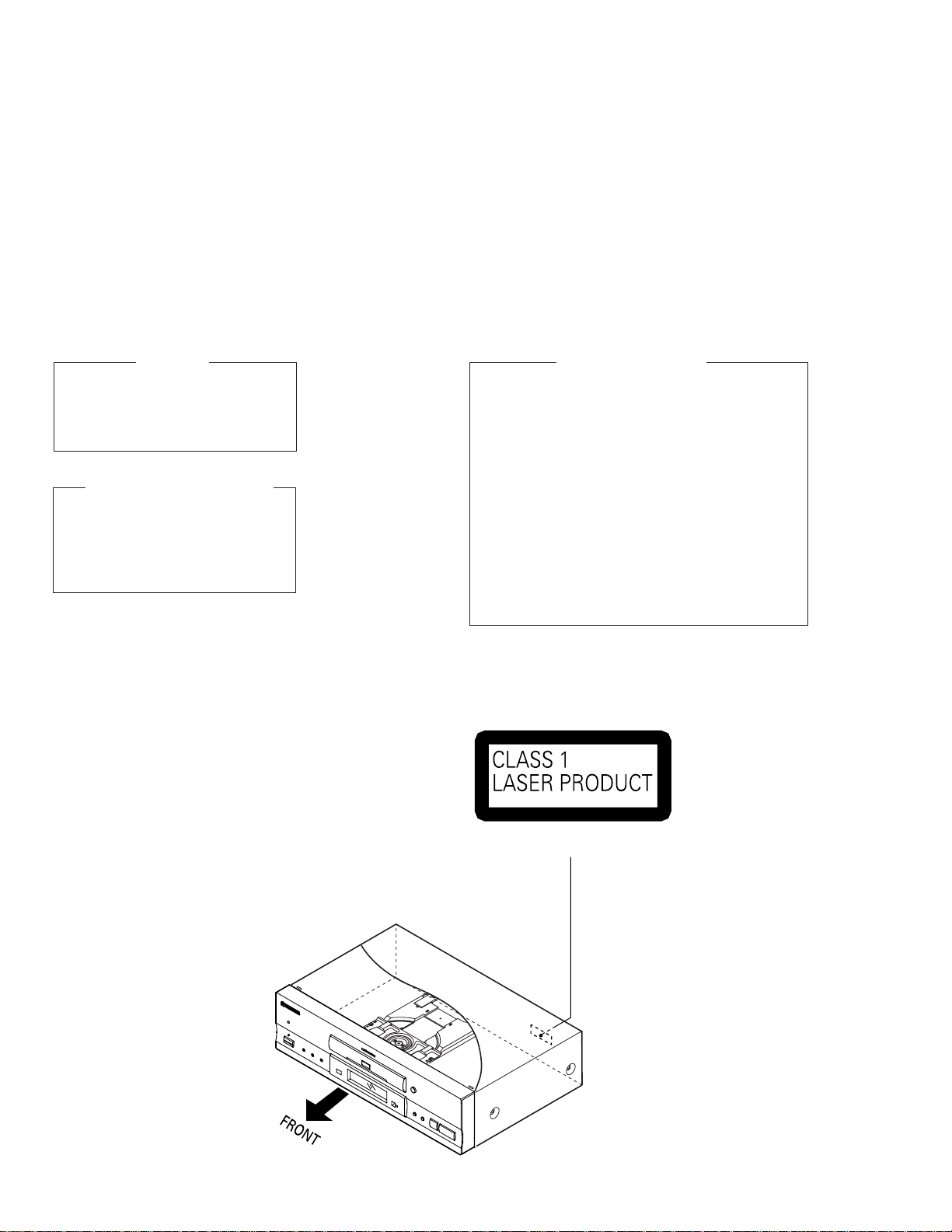
IMPORTANT
THIS PIONNER APPARATUS CONTAINS
LASER OF CLASS 1.
SERVICING OPERATION OF THE APPARATUS
SHOULD BE DONE BY A SPECIALLY
INSTRUCTED PERSON.
LASER DIODE CHARACTERISTICS
•FOR DVD
MAXIMUM OUTPUT POWER : 7 mW
WAVELENGTH : 650 nm
•FOR CD
MAXIMUM OUTPUT POWER : 5 mW
WAVELENGTH : 780-785 nm
LABEL CHECK
Additional Laser Caution
1. Inside detection switch (S201 on the SMEB assy) and loadingstatus detection switch (S301 on the LOSB assy) are detected
by the microprocessor (IC501 in the DVDM assy).
• To permit the laser diode to oscillate, it is required to set the
inside detection switch for the inside position (S201 : ON) and to
set the loading-status detection switch for the clamp position (the
center terminal of S301 is shorted to +5V). The 650 nm laser
diode for DVD oscillation will continue if pin 19 of IC101 is shorted
to +5V (fault condition) in the DVDM assy.
The 780 nm laser diode for CD oscillates if pin 20 of IC101 is
shorted to +5V in the DVDM assy.
In the test mode ∗ , the laser diode oscillates when microprocessor detects a PLAY signal, or when the PLAY key is pressed
(S113 ON in the FLKB assy), with the above requirements satisfied.
2. When the cover is open, close viewing through the objective lens
with the naked eye will cause exposure to the laser beam.
∗ Refer to the service guide RRV2004.
(Printed on the Rear Panel)
2
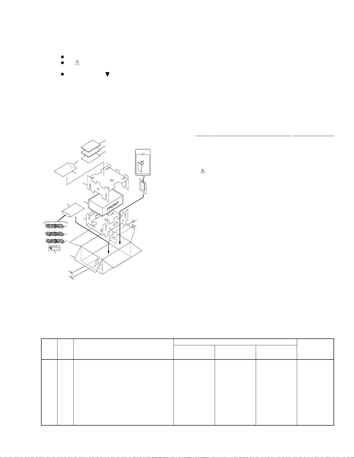
2. EXPLODED VIEWS AND PARTS LIST
NOTES:
2.1 PACKING
Parts marked by «NSP» are generally unavailable because they are not in our Master Spare Parts List.
The mark found on some component parts indicates the importance of the safety factor of the part.
Therefore, when replacing, be sure to use parts of identical designation.
Screws adjacent to mark on product are used for disassembly.
(1) PACKING PARTS LIST
Mark No. Description Part No.
1 Instruction Manual VRE1074
(English/French/German/Italian)
2 Instruction Manual VRF1045
(Spanish/Portuguese/Dutch/Swedish)
NSP 3 Warranty Card ARY7022
NSP 7 Battery(R6P,AA) VEM-013
4 Power Cord ADG1127
5 Audio Cord (L=1.5m) VDE1033
6 Video Cord (L=1.5m) VDE1048
8 Remote Control Unit VXX2601
(CU-DV025)
9 Battery Cover VNK4334
10 Polyethylene Bag Z21-038
11 Protector A VHB1065
12 Protector B VHB1066
13 Packing Case VHG1779
14 Mirror Mat Sheet VHL1012
15 Region Label See contrast table (2)
16 Label See contrast table (2)
10
11
10
14
12
4
5
6
7
13
15
16
(Except WY Type)
1
2 (WY Type Only)
3 (Except
WY/RD
Type)
15
16 (Except
WY Type)
8
9
DV-717
(2) CONTRAST TABLE
WY, WY/RD and WY/RE types are constructed the same except for the following :
Part No.
Mark
No.
Symbol and Description Remarks
WY
type
2 Instruction Manual VRF1045 Not used Not used
(Spanish/Portuguese/Dutch/Swedish)
NSP 3 Warranty Card ARY7022 Not used ARY7022
15 Region Label P2 VRW1701 Not used Not used
15 Region Label P4 Not used VRW1705 Not used
15 Region Label P5 Not used Not used VRW1755
16 RD Label Not used VRW1761 Not used
16 RE Label Not used Not used VRW1756
WY/RD
type
WY/RE
type
3
DV-717
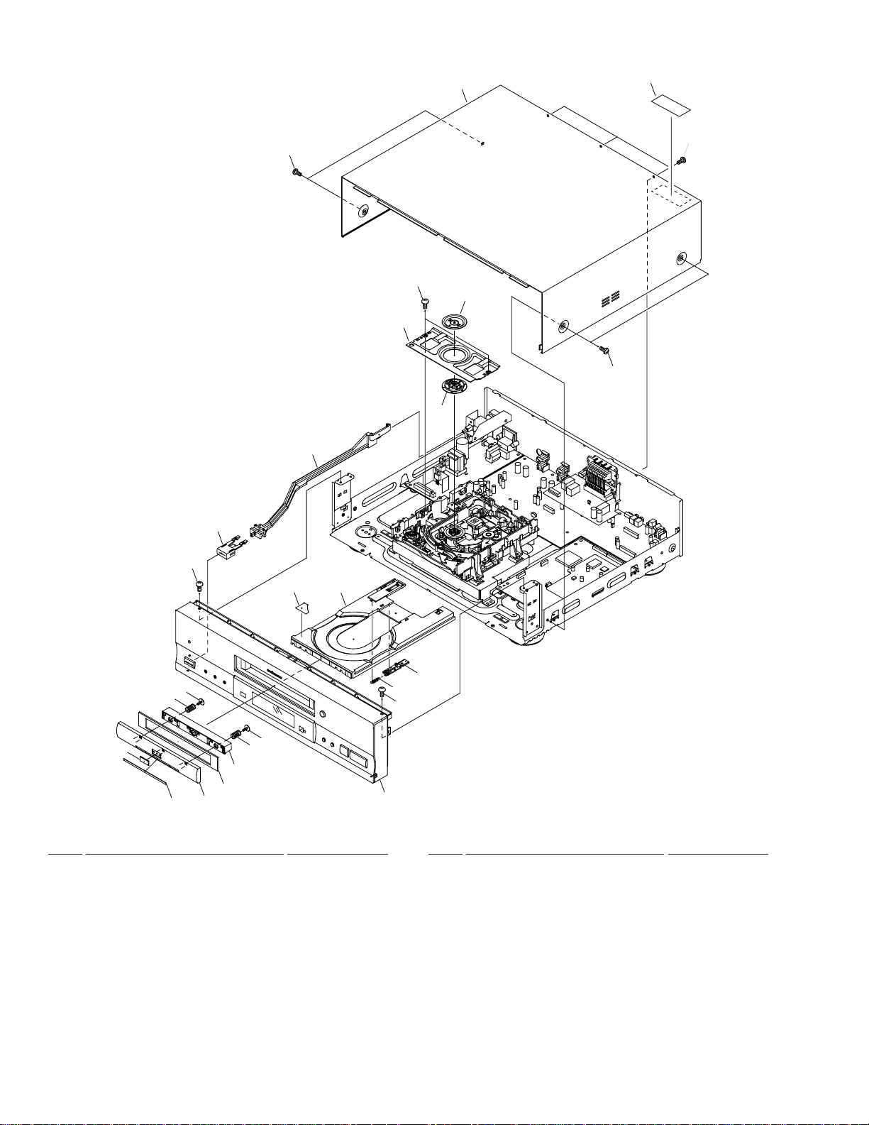
2.2 EXTERIOR SECTION
17
21
13
18
12
15
20
16
14
17
22
19
10
7
6
7
2
3
1
6
5
4
11
(1) EXTERIOR SECTION PARTS LIST
Mark No. Description Part No.
1 Door Plate VAH1312
2 DVD Plate VAM1077
3 Door Panel VNK4324
4 Door Cushion VEC2008
5 Door Holder VNK4325
9
8
19
Refer to «2.3 FRONT PANEL SECTION»
Mark No. Description Part No.
11 Tray VNK4333
12 Clamper VNL1738
13 Bridge VNE2069
14 Clamper Plate VNE2068
15 Bonnet Case S VXX2617
6 Door Spring VBH1305
7 Screw VBA1057
8 Spring VBH1277
9 Tray Stopper VNL1739
10 Label VRW1628
16 Screw BBZ30P080FMC
17 Screw BCZ40P060FNI
18 Screw BPZ26P080FZK
19 Screw BBT30P080FCC
20 Label VRW1699
21 PW Joint VNK4327
22 Power Button VNK4159
4
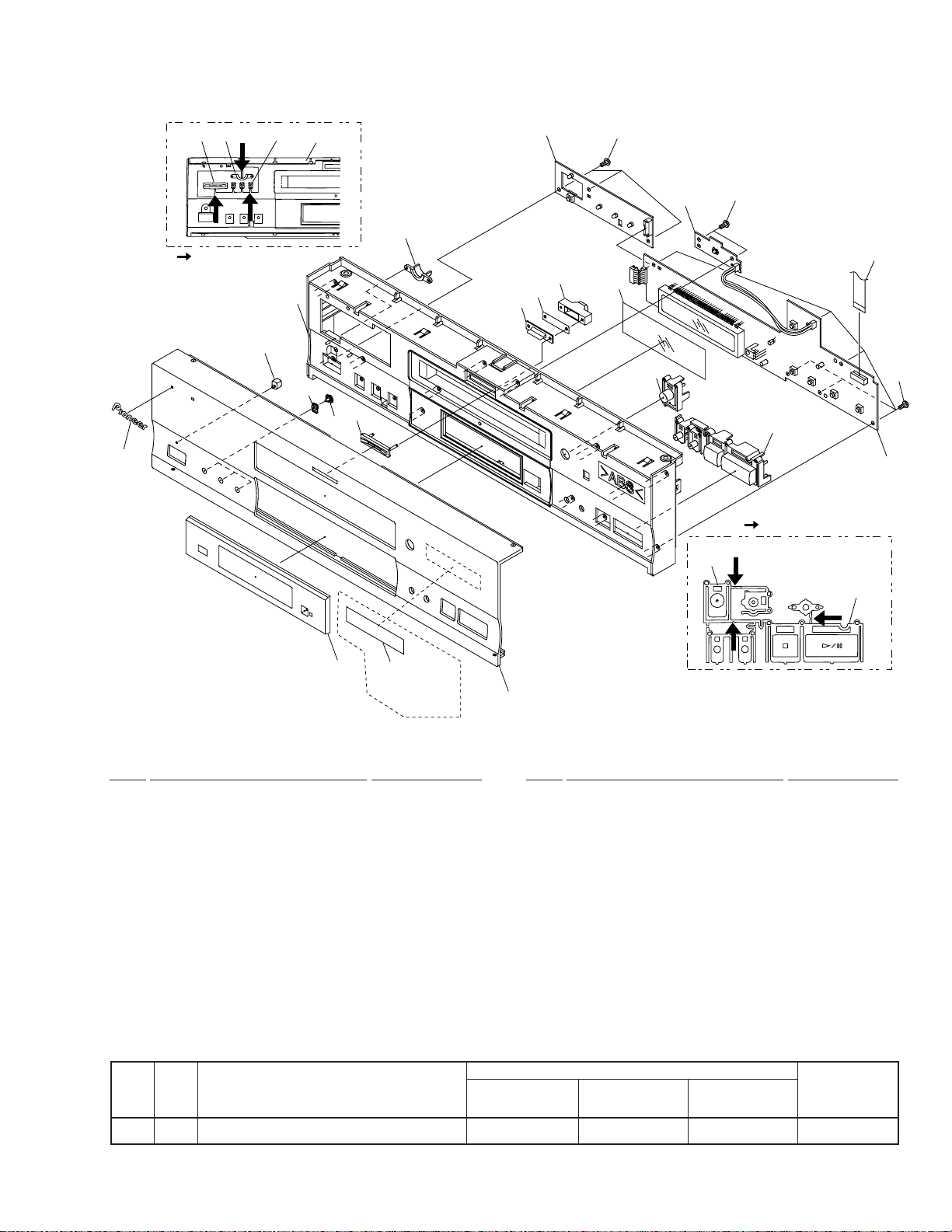
2.3 FRONT PANEL SECTION
DV-717
7(4/4)
:Cut position
3
7(3/4) 7(1/4)7(2/4)
7(1/4)
4
7(3/4)
7(4/4)
5
7(2/4)
15
11
10
9
12
17
8(2/2)
14
17
16
17
8(1/2)
13
:Cut position
8(2/2)
1
6
WY/RD
Type Only
2
(1) FRONT PANEL SECTION PARTS LIST
Mark No. Description Part No.
1 FL Lens VEC2007
2 Front Almi VAH1298
3 Name Plate G PAN1377
4 LED Lens PNW2019
5 LED Lens VNK4326
NSP 6 Getter See contrast table (2)
7 Panel Base VNK4323
8 Main Key VNK4095
9 Illumination Lens VNK4168
10 Illumination Filter VEC1950
Mark No. Description Part No.
11 Illumi Holder VNK4098
12 FL Filter VEC2016
13 FLKY Assy VWG1980
NSP 14 DIRB Assy VWG1991
NSP 15 PWSB Assy VWG1988
16 Flexible Cable VDA1690
17 Screw BBZ30P080FMC
(2) CONTRAST TABLE
WY, WY/RD and WY/RE types are constructed the same except for the following :
Part No.
Mark
No.
Symbol and Description Remarks
WY
type
NSP 6 Getter Not used VRW1757 Not used
WY/RD
type
WY/RE
type
8(1/2)
5
DV-717
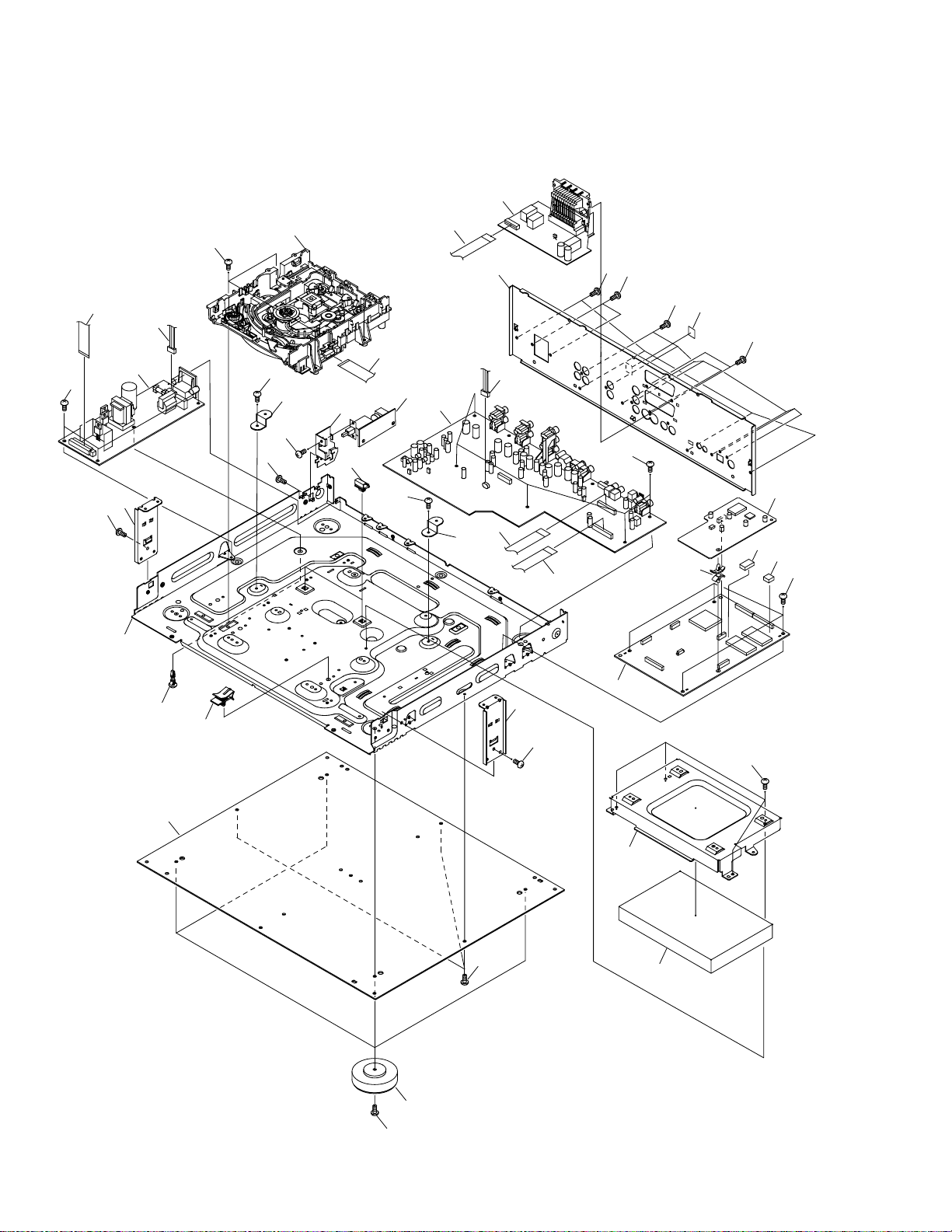
2.4 BOTTOM SECTION
20
25
20
Refer to
«2.5 LOADING MECHANISM ASSY»
20
20
33
18
26
7
8
9
19
32
10
6
3
20
11
31
12
30
17
29
28
7
27
21
20
21
21
34 (Except WY Type)
21
22
24
23
13
20
4
5
2
1
20
6
20
20
14
20
15
16
6

(1) BOTTOM SECTION PARTS LIST
Mark No. Description Part No.
1 Insulator PNW2766
NSP 2 Bottom Plate PNA2376
NSP 3 Chassis VNA1979
NSP 4 PCB Holder PNW2029
5 Flat Cable Clip VEC2018
DV-717
Mark No. Description Part No.
21 Screw BBZ30P080FMC
NSP 22 PC Support Cushion VEC2033
NSP 23 PC Support Spacer VEC2032
24 PC Support DEC1932
25 Flexible Cable (26p) VDA1688
NSP 6 Panel Stay VNE2156
NSP 7 PCB Base RNE1221
NSP 8 Power-Holder VNE2123
NSP 9 P.Plate Holder PNY-405
10 Power Supply Unit VWR1306
NSP 11 MSWB Assy VWG1996
12 A VJB Assy VWV1617
13 DNRB Assy VWV1619
14 DVDM Assy VWS1349
NSP 15 Mecha Holder VNE2157
16 Mecha Cushion VEC2011
17 Rear Panel See contrast table (2)
NSP 18 Loading Mecha. Assy VWT1157
19 Screw BBZ30P100FMC
20 Screw ABZ30P080FCC
26 Flexible Cable (12p) VDA1692
27 Flexible Cable (26p) VDA1694
28 Flexible Cable (22p) VDA1696
29 Connector Assy PF02PP-S20
30 SCRB Assy VWV1623
31 Flexible Cable (22p) VDA1699
32 Housing Assy VKP2194
33 Screw PMB30P080FZK
34 Region Label See contrast table (2)
(2) CONTRAST TABLE
WY, WY/RD and WY/RE types are constructed the same except for the following :
Part No.
Mark
No.
Symbol and Description
WY
type
17 Rear Panel VNA1996 VNA2043 VNA2043
34 Region Label R4 Not used VRW1704 Not used
34 Region Label R5 Not used Not used VRW1754
WY/RD
type
WY/RE
type
Remarks
7
DV-717
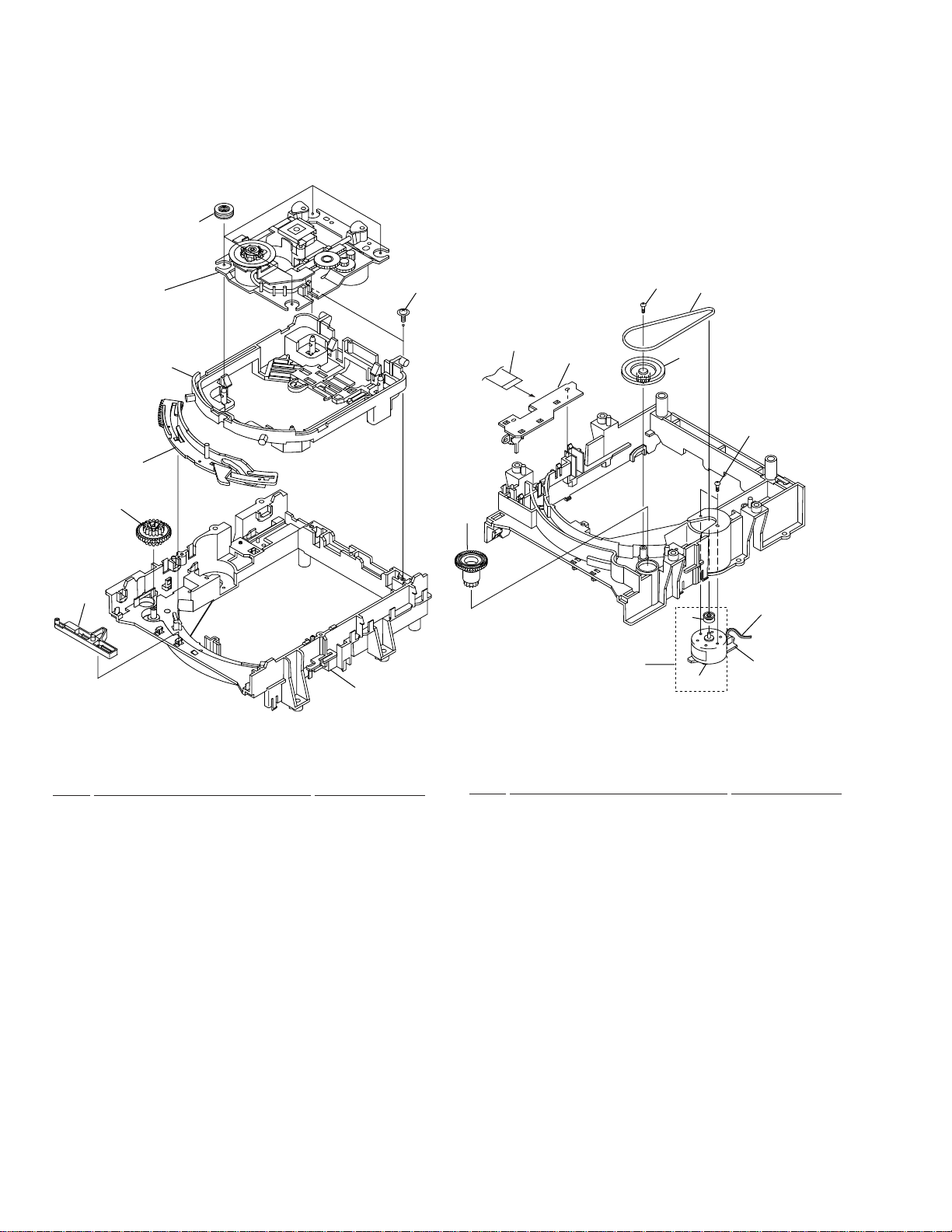
2.5 LOADING MECHANISM ASSY
• Top View • Bottom View
20
Refer to
«2.6 SERVO MECHANISM
ASSY»
5
1
19
3
4
2
18
10
6
9
17
11
13
7
8
16
15
14
12
LOADING MECHANISM ASSY PARTS LIST
Mark No. Description Part No.
1 Servo Mechanism Assy-S VXX2606
2 Screw DBA1006
3 Drive Cam VNL1736
4 Drive Gear VNL1735
5 Lock Plate VNL1820
6 Loading Base VNL1730
7 Belt VEB1260
8 Gear Pulley VNL1733
NSP 9 LOSB Assy VWG1885
10 Loading Gear VNL1734
8
Mark No. Description Part No.
11 Loading Motor Assy VXX2505
12 DC Motor / 0.3W PXM1027
13 Motor Pulley PNW1634
NSP 14 LOMB Assy VWG1886
15 Connector Assy VKP2184
(LOMB CN401 – LOSB CN306)
16 Screw VBA1055
17 Screw Z39-019
18 Flexible Cable (08P) VDA1698
(LOSB CN303 – SMEB CN202)
19 Float Base VNL1815
20 Floating Rubber VEB1286
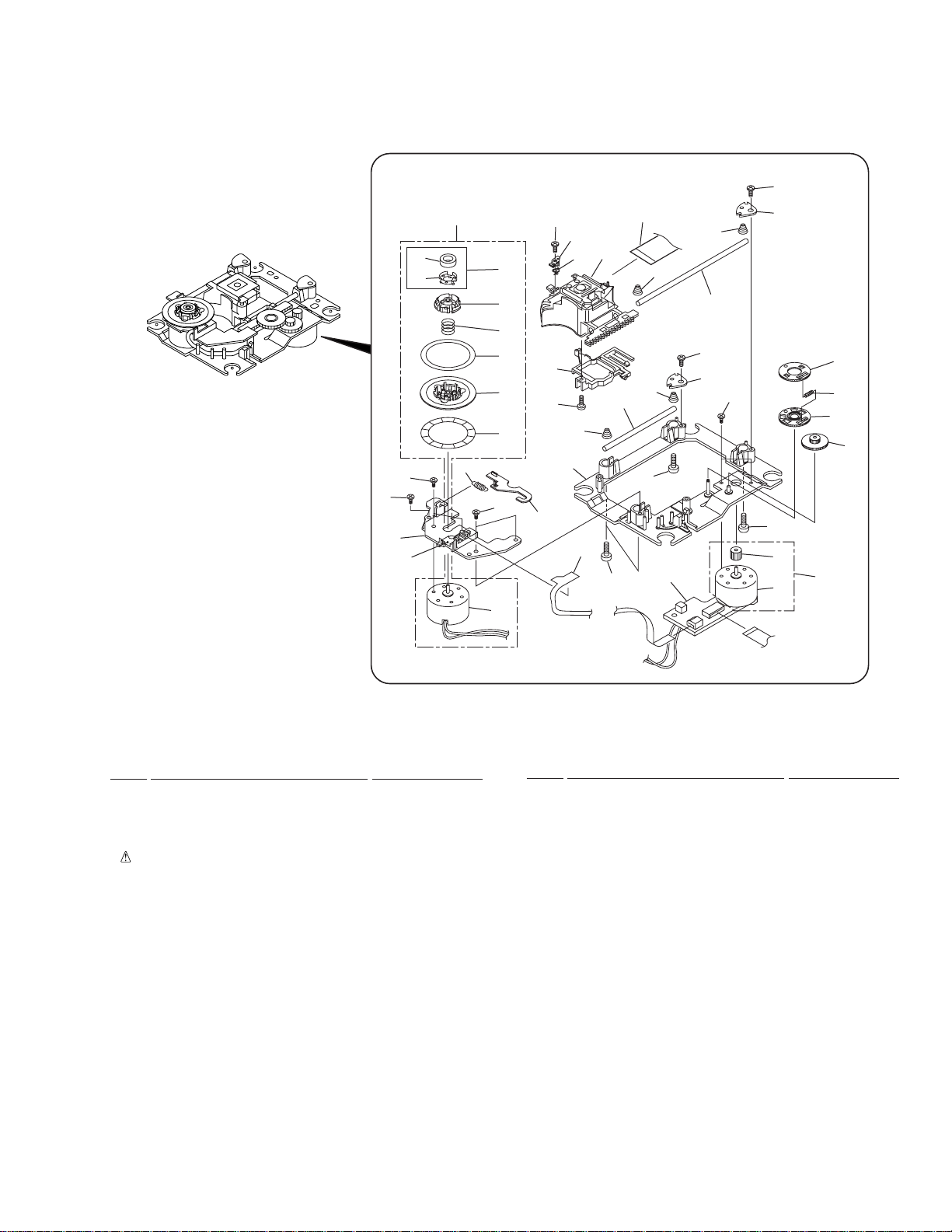
2.6 SERVO MECHANISM ASSY
• Top View
DV-717
37
37
17
31
24
30
16
35
33
28
34
19
8
6
20
12
9
37
4
15
22
33
10
23
21
2
38
10
5
10
13
37
10
14
7
7
18
32
1
18
26
11
25
27
7
29
36
3
SERVO MECHANISM ASSY PARTS LIST
Mark No. Description Part No.
NSP 1 SMEB Assy VWG1968
NSP 2 FGSB Assy VWG2009
3 Motor VXM1074
4 Motor VXM1075
5 Pickup Assy VWY1050
6 Table Sheet DEC2040
7 Screw VBA1058
8 Centering Spring VBH1278
9 Hook Spring VBH1291
10 Skew Spring VBH1303
11 Gear Spring VBH1308
NSP 12 Reflected Sheet VEC1959
13 Guide Bar VLL1504
14 Sub-guide Bar VLL1505
15 Hold Spring VNC1017
NSP 16 Magnet Holder VNE2070
NSP 17 Motor Base VNE2154
NSP 18 Cover VNE2155
19 Centering Ring VNL1746
NSP 20 Disc Table VNL1747
Mark No. Description Part No.
21 Hook VNL1770
22 FFC Holder VNL1802
23 Mechanism Base VNL1806
24 FG Holder VNL1807
25 Gear A VNL1808
26 Gear B VNL1809
27 Gear C VNL1810
28 Slider VNL1811
29 Gear D VNL1814
NSP 30 Magnet VYM1024
31 Screw JFZ17P025FZK
32 Screw JGZ17P028FMC
33 Screw VBA1051
34 Magnet Holder Assy VXX2507
35 Spindle Motor Assy VXX2604
36 Carriage Motor Assy VXX2605
37 Screw PBA1069
38 Flexible Cable (24P) VDA1701
(DVDM CN120 – Pickup Assy)
9
1
23
DV-717
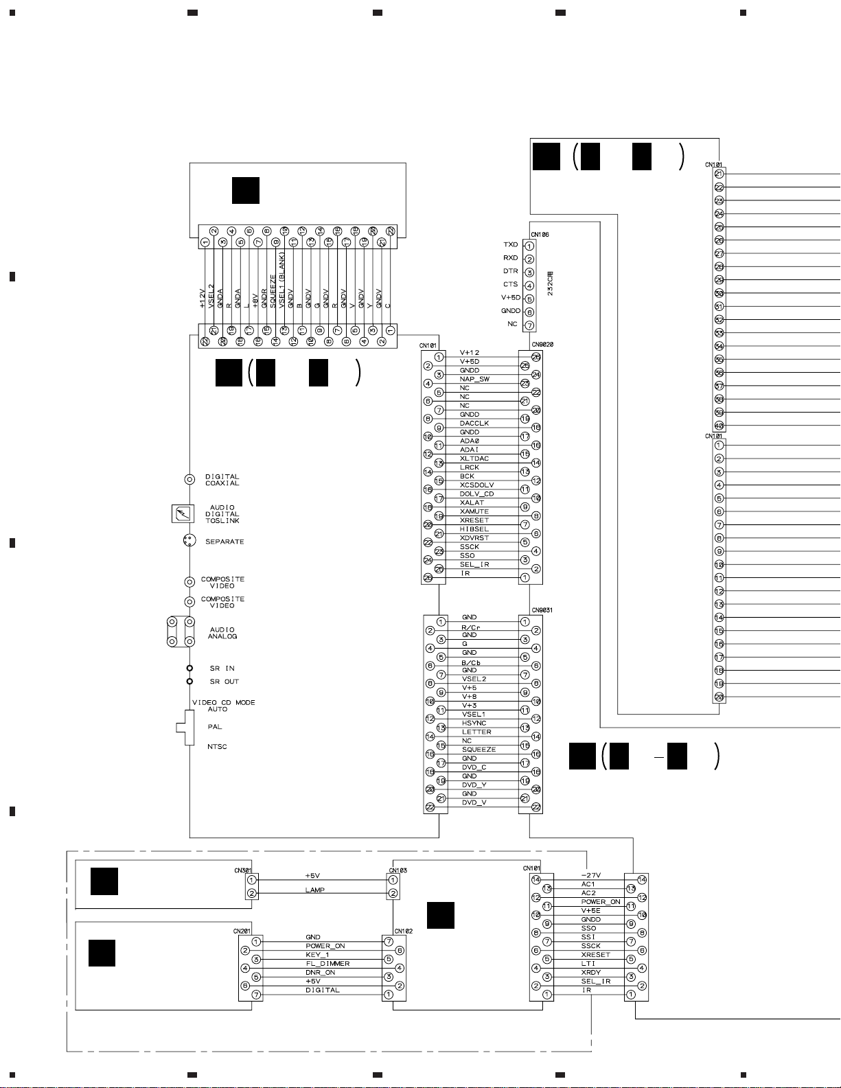
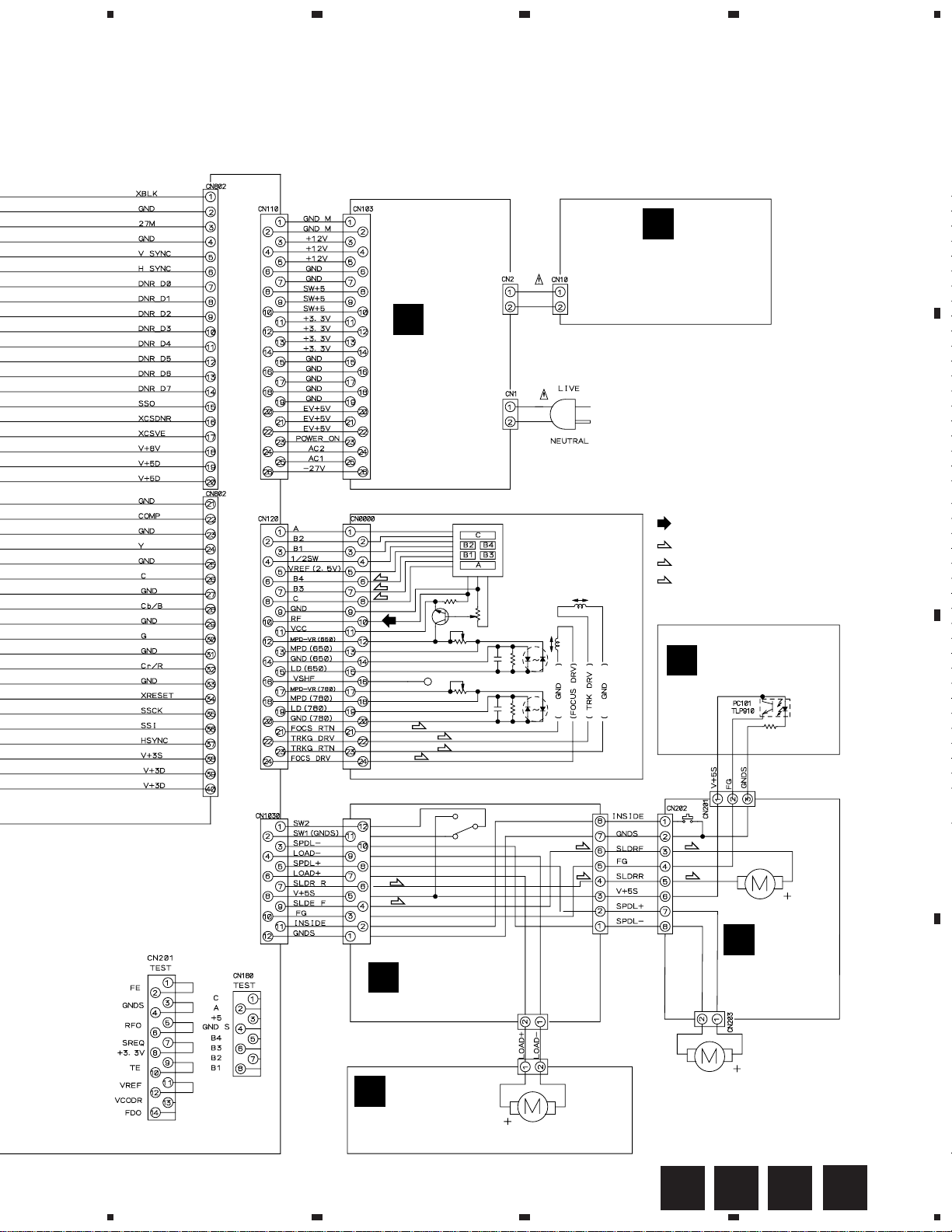
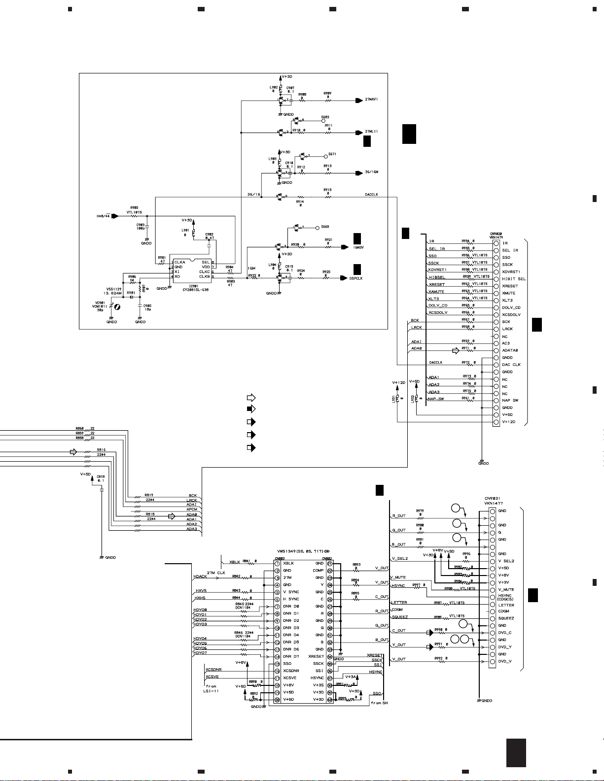
3. SCHEMATIC DIAGRAM
3.1 OVERALL CONNECTION DIAGRAM, LOMB,
A
LOSB, SMEB and FGSB ASSEMBLIES
SCRB ASSY
K
(VWV1623)
I
I I
1/2, 2/2
CN1001
CN103
J
J J
1/2, 2/2
DNRB ASSY
(VWV1619)
4
B
C
AVJB ASSY (VWV1617)
CN102
H
H H
1/3 3/3
DVDM ASSY
(VWS1349)
DILB ASSY
G
(VWG1991)
CN602
E
D
F PWSB ASSY
(VWG1988)
FLKB ASSY
(VWM1860)
10
1234
FLKY ASSY
(VWG1980)
5
678
DV-717
Note : When ordering service parts, be sure to refer to «EXPLODED VIEWS and P AR TS LIST» or «PCB PARTS LIST».
L
MSWB ASSY
(VWG1996)
M
POWER
SUPPLY
ASSY
(VWR1306)
A
B
CN301
(F)
(F)
(T)
(F)
(T)
(T)
(F)
(S)
(S)
LOSB ASSY
B
(VWG1885)
PICKUP ASSY
(VWY1050)
CN302
(S)
(S)
CN303
B2B-PH-K-S
: RF SIGNAL ROUTE
(F)
: FOCUS SERVO LOOP LINE
(T)
: TRACKING SERVO LOOP LINE
(S)
: SLIDER SERVO LOOP LINE
FGSB ASSY
D
(VWG2009)
R101
680
(S)
(S)
CARRIAGE MOTOR ASSY
VXX2605
C
SMEB ASSY
(VWG1968)
C
CN401
LOMB ASSY
A
(VWG1886)
5
6
B2B-PH-K-S
LOADING
MOTOR
ASSY
:VXX2505
SPINDLE MOTOR ASSY
7
VXX2604
CBA
D
8
11
D
1
23
DV-717
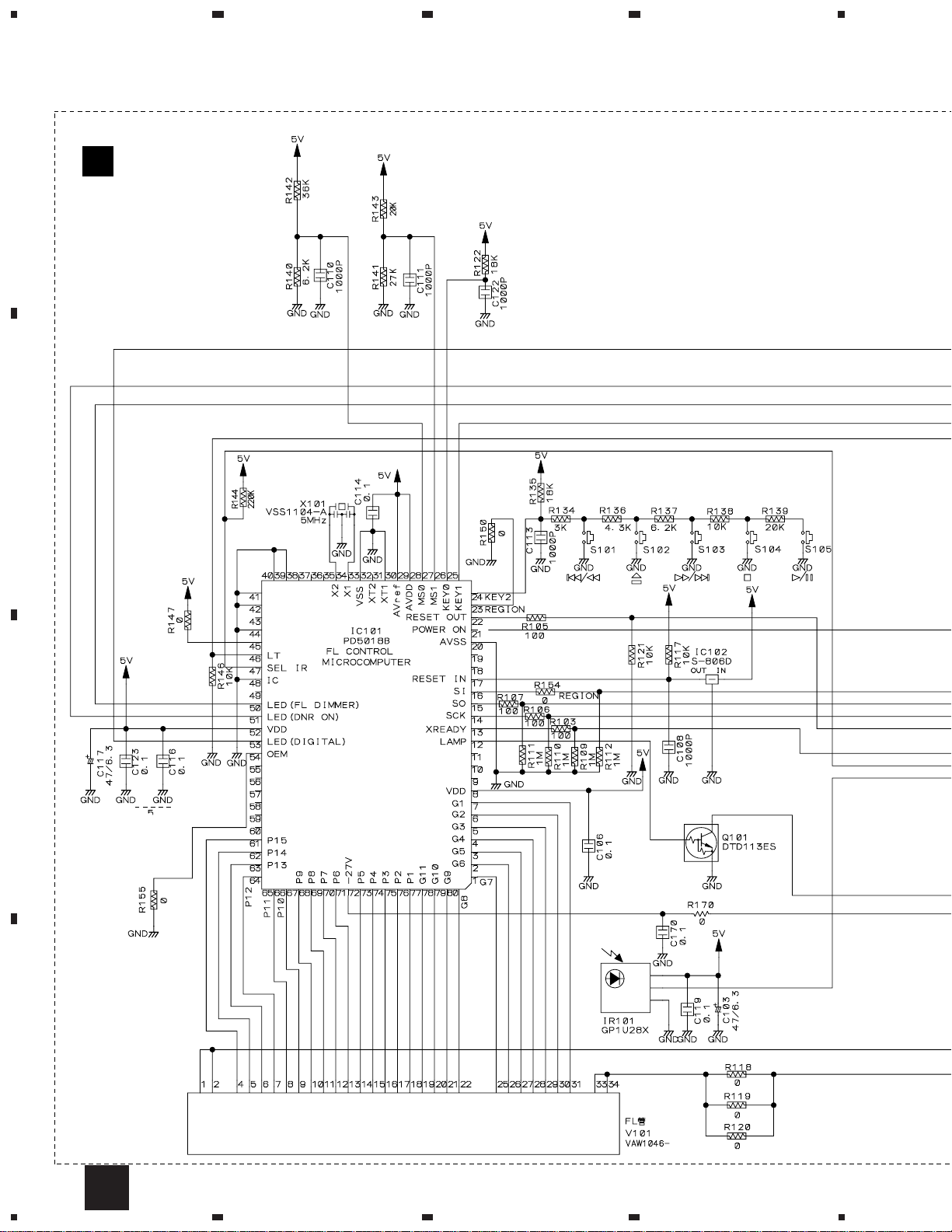
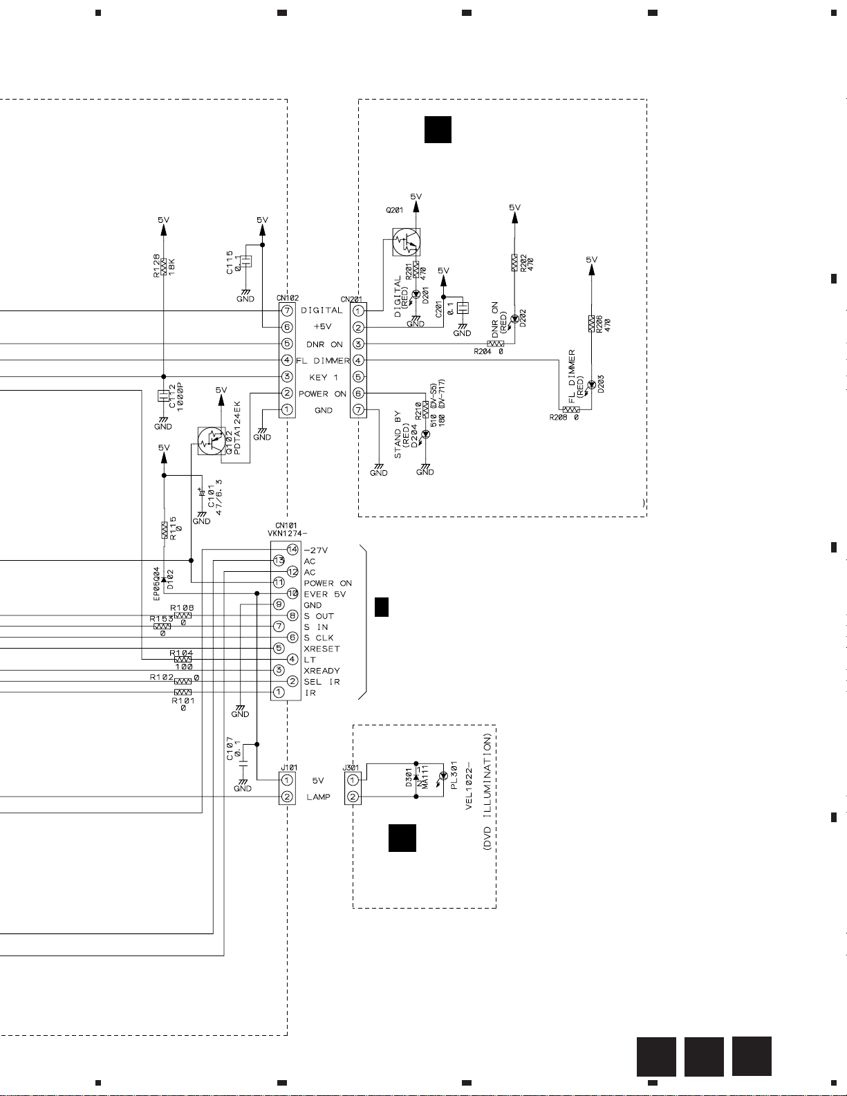
3.2 FLKY, PWSB and DILB ASSEMBLIES
4
A
E
FLKY ASSY
(VWG1980)
B
C
D
12
E
1234
5
678
DV-717
PWSB ASSY
F
(VWG1988)
A
B
2/3
H
CN602
G
DILB ASSY
(VWG1991)
SWITCHES:
FLKY ASSY
S101: 4/1
S102: 0
S103: ¡/¢
S104: 7
S105: 6
FLKB ASSY
(VWM1860)
C
D
FE
5
6
7
G
8
13
1
DV-717
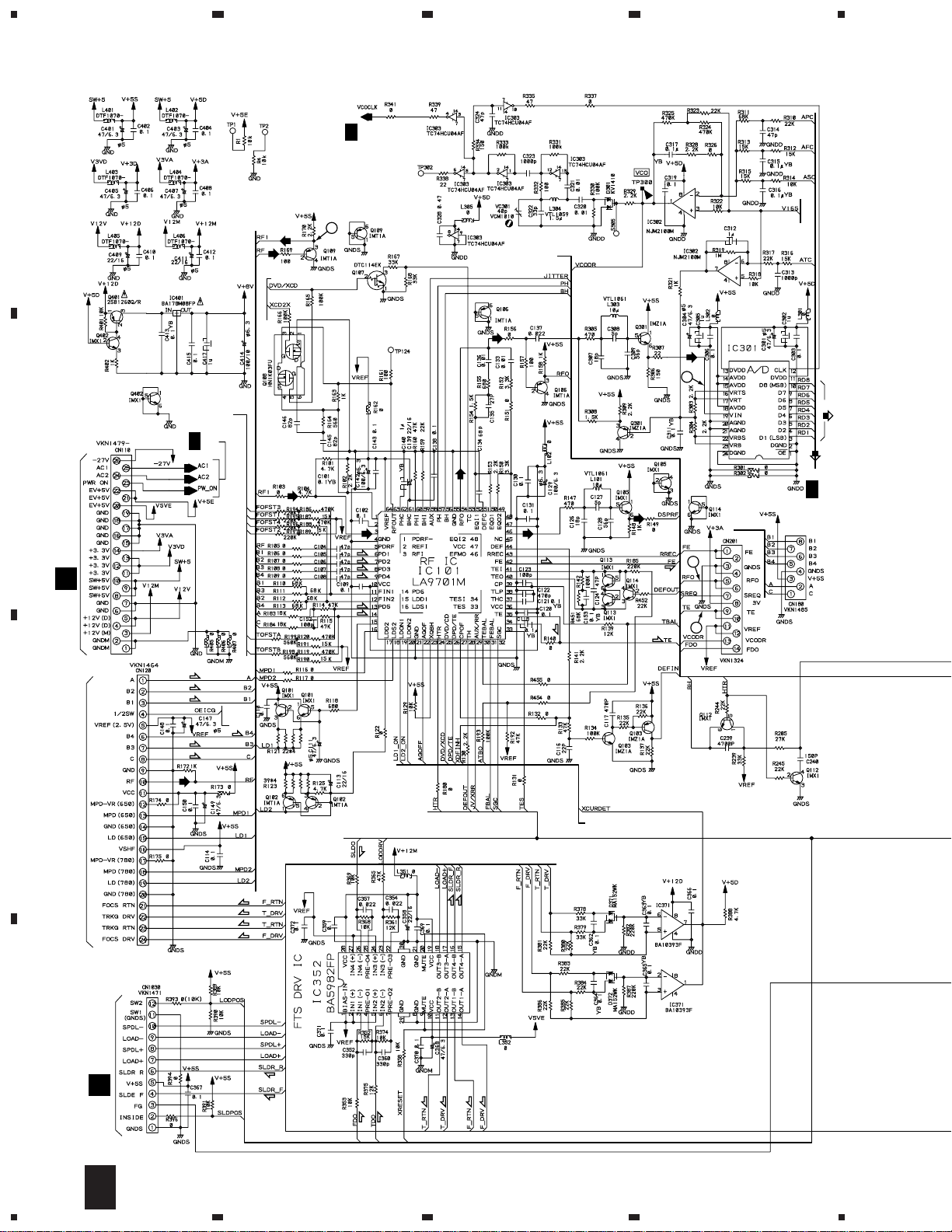
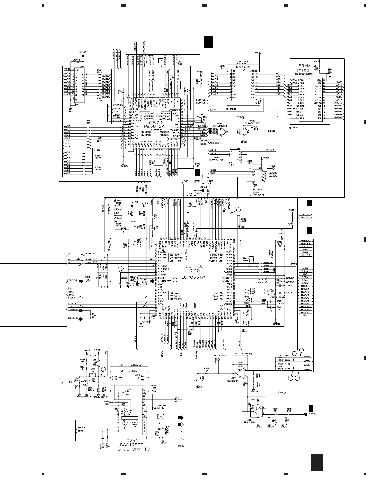
3.3 DVDM ASSY (1/3)
23
4
(4/6)
(DVD)
(1/6)
(5/6)
(CD)
(6/6)
1/2
from IC261
2/2
ADC1175CIJMX
(DVD)
3
(DVD)
(DVD)
to IC701
H
2/3
(CD)
(F)
(F)
to CN120
2
H
2/3
(2/6)
A
(3/6)
1
to IC501
to IC501
H
2/3
B
(DVD)
(F)
CN103
M
(T)
(T)
(F)
(F)
to
IC501
(F)
(F)
(T)
(T)
4
(T)
C
to IC501
PICKUP ASSY
(F)
(T)
(T)
(F)
D
CN301
B
(S)
(S)
(S)
(S)
2/2
1/2
(T)
(T)
(F)
(F)
(F)
(T)
14
1/3
H
1234
5
678
DV-717
IC507
TC74VHCT245AFT
to IC101
from Q107,Q108
to CN120
to IC101
H
1/3
DVDM ASSY(1/3) (VWS1349)
A
1/2 2/2
(1/2)
H
3/3
B
(2/2)
H
2/3
6
(CD)
to IC601
(T)
(F)
(CD)
(CD)
H
2/3
to IC701
(T)
(F)
(CD)
(S)
(F)
(T)
(CD)
7
(S)
(F)
(T)
5
C
8
9
2/2
1110
to IC302
H
1/2
LEVEL SHIFT
5
6
: RF SIGNAL ROUTE
: ROM DATA SIGNAL ROUTE
(F)
: FOCUS SERVO LOOP LINE
(T)
: TRACKING SERVO LOOP LINE
(S)
: SLIDER SERVO LOOP LINE
7
2/3
H
1/3
8
D
15
1
DV-717
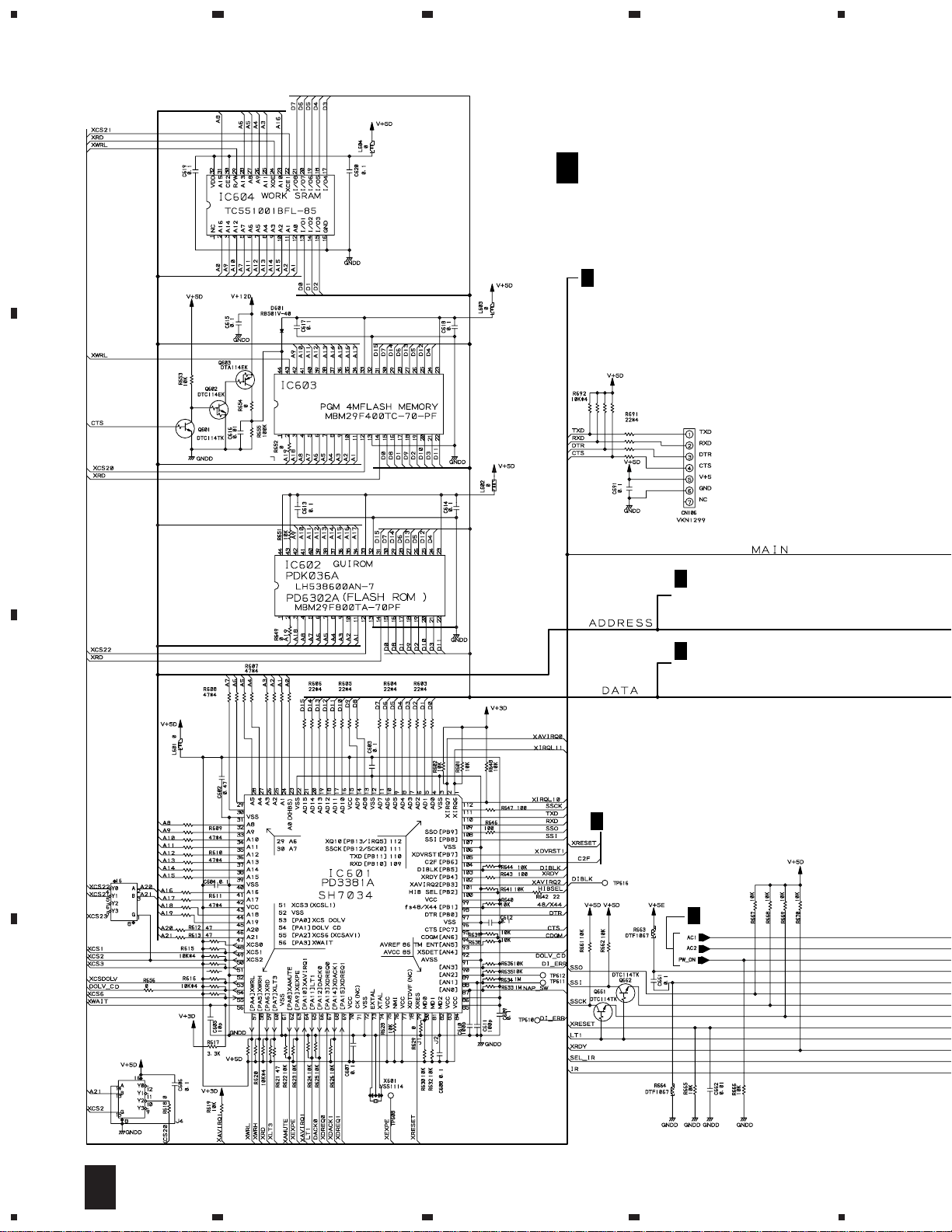
3.4 DVDM ASSY (2/3)
23
4
A
H
2/3
DVDM ASSY(2/3)
(VWS1349)
H
3/3
XCSDOLV,XCS6,XWRL,XWRH,XLT3,
XAMUTE,XDACK1,XDREQ1,IR,SEL-IR,
48/44,XDVRST1,XAVIRQ0,NSP-SW,
SSCK,SSO,XRESET
VYW1518
B
H
3/3
ADDRESS
A2–A10
H
3/3
DATA
C
H
1/3
IC605(1/2)
TC74VHC139FT
H
1/3
IC605(2/2)
TC74VHC139FT
D
16
2/3
H
1234
5
: AUDIO SIGNAL ROUTE
: ROM DATA SIGNAL ROUTE
(DVD)
H
3/3
SDATA
(DVD)
678
DV-717
A
B
from IC701
H
3/3
from IC801
TC74VHCT541AFT
H
3/3
IC703
(DVD)
H
1/3
H
1/3
from IC301
H
3/3
(DVD)
MONITOR OUTPUT
H
1/3
from IC301
H
1/3
C
SERVO
H
1/3
H
to IC801
H
3/3
H
3/3
(CD)
1/3
H
3/3
H
1/3
E
CN101
to IC801
H
3/3
5
from IC201
H
6
1/3
H
1/3
2/3
H
7
8
17
D
1
DV-717
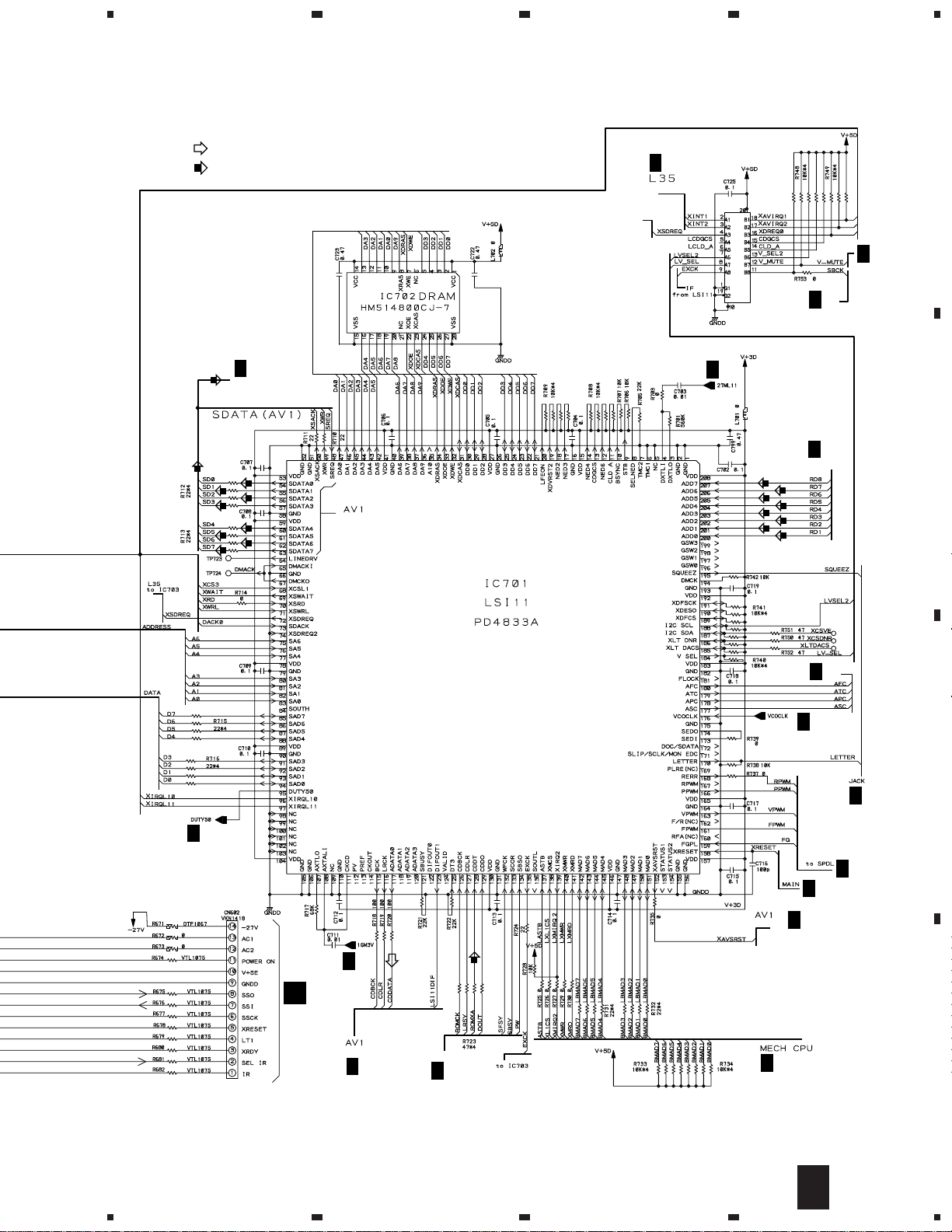
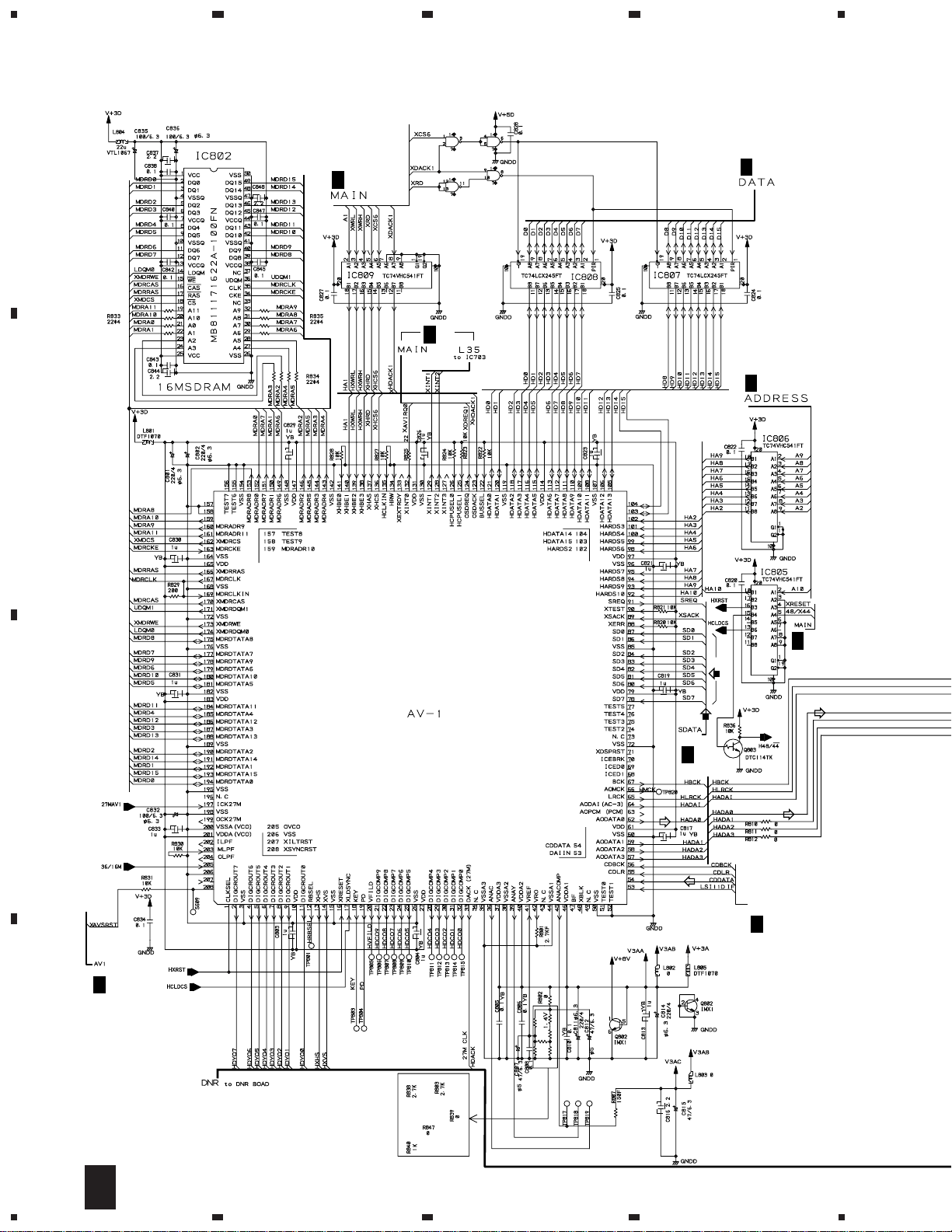
3.5 DVDM ASSY (3/3)
A
B
23
IC810(1/4)
TC74VHC00FT
IC810(2/4)
TC74VHC00FT
H
2/3
IC810(4/4)
TC74VHC00FT
H
2/3
IC810(3/4)
TC74VHC00FT
4
H
2/3
H
2/3
H
2/3
(DVD)
from IC701
H
2/3
(DVD)
from IC701
H
2/3
IC801
MB86371C
C
from IC701
H
2/3
D
18
3/3
H
1234
5
678
DV-717
CLOCK GENERATOR SECTION
IC906(1/3)
IC906 :
TC7W04F
IC906(2/3)
IC904(1/3)
IC904(2/3)
IC904 :
TC7W04F
IC904(3/3)
: AUDIO SIGNAL ROUTE
: ROM DATA SIGNAL ROUTE
(V/CB)
: V/CB SIGNAL ROUTE
(Y)
: Y SIGNAL ROUTE
(C)
: C SIGNAL ROUTE
IC906(3/3)
H
for IC701
H
for IC201
for IC801
H
2/3
for IC801
2/3
1/3
H
H
3/3
DVDM ASSY(3/3)
(VWS1349)
2/3
A
1
2
3
4
5
6
7
8
9
10
11
12
13
14
15
16
17
18
19
20
21
22
23
24
25
26
1/2
I
CN101
B
H
2/3
17
18
15
14
(C)
(Y)
1613
1
2
R
3
4
5
6
B
7
8
9
10
11
12
13
14
15
16
17
18
19
20
21
22
2/2
I
CN102
C
D
3/3
H
5
6
7
8
19
DV-717
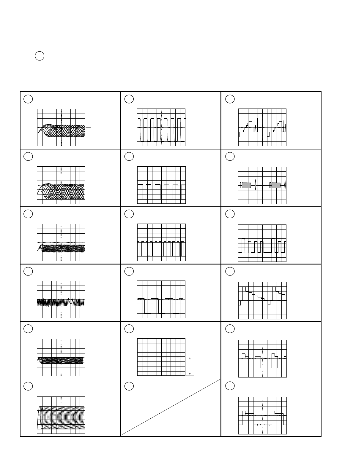
• WAVEFORMS OF DVDM ASSY
Note : No. in the table correspond to the number on the schematic diagram.
Measurement condition : No. 1 to 4 and 6 to 11 : Disc MJK1, Title 1-chp 1
Q109-Emitter (RF)
1
V: 100mV/div. H: 0.1µS/div.
TP (RFO)
2
V: 500mV/div. H: 0.1µS/div.
IC301-pin 19 (RF for A/D converter)
3
V: 1V/div. H: 0.2µS/div.
No. 5 : CD, ABEX-784 Track 1
No. 13 to 14 : MJK1, Title 1-chp 4
No. 15 to 18 : MJK1, Title 1-chp 5
Q281-Collector (FG)
7
V: 1V/div. H: 5mS/div.
DC 2V
Foot of R261 (FPWM)
8
V: 1V/div. H: 10µS/div.
Foot of R262 (VPWM)
9
V: 1V/div. H: 10µS/div.
CN9031-pin 20 (Y output)
13
V: 500mV/div. H: 10µS/div.
CN9031-pin 18 (C output)
14
V: 500mV/div. H: 10µS/div.
CN9031-pin 6 (B output when
15
selecting color difference output)
V: 500mV/div. H: 10µS/div.
TP (Tracking Error)
4
V: 1V/div. H: 2mS/div.
IC201-pin 39 (EFM before slice)
5
V: 1V/div. H: 1µS/div.
IC201-pin 1 (EFM)
6
V: 1V/div. H: 0.2µS/div.
Foot of R263 (PPWM)
10
V: 1V/div. H: 0.2µS/div.
Foot of R264 (RPWM)
11
12
DC1.4V
CN9031-pin 20 (Y output when
16
selecting color difference output)
V: 500mV/div. H: 10µS/div.
CN9031-pin 2 (R output when
17
selecting color difference output)
V: 500mV/div. H: 10µS/div.
CN9031-pin 4 (G output when
18
selecting color difference output)
V: 500mV/div. H: 10µS/div.
20
Loading…
Pioneer DV-717 DVD Player PDF User Guides and Manuals for Free Download: Found (1) Manuals for Pioneer DV-717 Device Model (Service Manual)
Pioneer DV-717 Service Manual
Details:
- Manufacturer: Pioneer
- Product Name/ID: Pioneer DV-717 / #741482
- Category: DVD Player
- File Path: pioneer/dv-717_741482.pdf
- Last Updated: 16 May 2025
- Description: The Pioneer DV-717 manual offers a thorough overview of setup, operational guidelines, and maintenance practices to help you get the most out of your device and avoid common issues.
- Document Type: User Manual
- Pages: 65
Download PDF
Read Online
The Pioneer DV-717 is a remarkable piece of technology that seamlessly blends high-quality video playback with versatile media support. Released as part of Pioneer’s impressive lineup of home entertainment systems, the DV-717 stands out with its robust features and sleek design. This DVD player is more than just a device for viewing films; it is an integral part of a comprehensive home theater setup that caters to both casual viewers and audiophiles.
One of the key aspects of the Pioneer DV-717 is its ability to handle a variety of formats. Unlike many standard DVD players that may limit users to basic media types, the DV-717 supports a wide range of formats, including:
- DVD Video
- DVD-R/RW
- CD Audio
- Audio CD-R/RW
- Video CD (VCD)
- MP3 CDs
This versatility makes the Pioneer DV-717 an ideal choice for anyone looking to enjoy their entire media collection without the hassle of compatibility issues. Whether it’s a classic DVD, a well-loved CD, or even modern formats like MP3, users can rest assured that this device will deliver excellent playback quality.
In terms of video performance, the Pioneer DV-717 doesn’t disappoint. It features high-resolution output, ensuring that images are sharp and vivid. The incorporation of advanced video processing technology enhances the overall viewing experience, providing richer colors and better contrast. This is particularly beneficial for those who enjoy watching films or TV shows on bigger screens. Additionally, the player supports various output resolutions, making it compatible with a range of televisions.
Audio quality is another hallmark of the Pioneer DV-717. It supports multiple audio formats and boasts a rich sound experience. The player includes high-resolution audio output options, which are crucial for audiophiles seeking that perfect sound. With its onboard Dolby Digital and DTS decoding capabilities, users can enjoy an immersive audio experience that complements their video viewing beautifully.
Aside from its impressive functionality, the build quality of the Pioneer DV-717 is noteworthy. The design is sleek and modern, easily fitting into any home entertainment setup without looking out of place. The user interface is intuitive, making navigation through menus and settings straightforward. Additionally, the remote control is well-designed, providing easy access to all features from the comfort of a couch.
To summarize the advantages of the Pioneer DV-717:
- Wide range of supported formats
- High-resolution video playback
- Excellent audio quality
- Sleek, modern design
- User-friendly interface
In conclusion, the Pioneer DV-717 is a versatile and high-quality DVD player that meets the needs of modern home entertainment enthusiasts. Its capability to handle various media formats combined with superior audio and video performance makes it an excellent investment. Whether you’re a film buff or an audio lover, the Pioneer DV-717 deserves a spot in your living room setup.
Pioneer DV-717 user guide recommended for: CDJ-2000NXS2, LD-V1000, DV-45A, DVD-V550, AVX-P8DVD.
The Pioneer DV-717 DVD Player manual (Pioneer Service manual, 65 pages) is completely safe to download (last scan date: 04/04/2025). You can rest assured of your safety when interacting with Pioneer DV-717 document.
1
VIA DVDJ
Installation manual Elan DVD Player Installation manual (File: elan-via-dvdj-installation-manual-36, 29th Jan 2025)
36
691
132
5
MCD296
Service manual Philips MCD296 User Manual (Service manual), @QF9M34
33
1411
325
8
CX-3311
Service manual PDF Manual (@9782JJ), Pioneer CX-3311 DVD Player (08.11.2024)
55
68
15