

FM Stereo
FM-AM Receiver
4-229-127-52(2)
Operating Instructions
Mode d’emploi
Manual de Instrucciones
Gebruiksaanwijzing
GB
FR
ES
NL
STR-DB940
STR-DB840
2000 Sony Corporation
WARNING
Precautions
To prevent fire or shock
hazard, do not expose the
unit to rain or moisture.
For customers in the United States
This symbol is intended to alert the user to the
presence of uninsulated “dangerous voltage”
within the product’s enclosure that may be of
sufficient magnitude to constitute a risk of
electric shock to persons.
This symbol is intended to alert the user to
the presence of important operating and
maintenance (servicing) instructions in the
literature accompanying the appliance.
INFORMATION
This equipment has been tested and found to
comply with the limits for a Class B digital
device, pursuant to Part 15 of the FCC Rules.
These limits are designed to provide
reasonable protection against harmful
interference in a residential installation.
This equipment generates, uses, and can
radiate radio frequency energy and, if not
installed and used in accordance with the
instructions, may cause harmful
interference to radio communications.
However, there is no guarantee that
interference will not occur in a particular
installation. If this equipment does cause
harmful interference to radio or television
reception, which can be determined by
turning the equipment off and on, the user
is encouraged to try to correct the
interference by one or more of the
following measures:
– Reorient or relocate the receiving
antenna.
– Increase the separation between the
equipment and receiver.
– Connect the equipment into an outlet on
a circuit different from that to which the
receiver is connected.
– Consult the dealer or an experienced
radio/TV technician for help.
CAUTION
You are cautioned that any changes or
modification not expressly approved in
this manual could void your authority to
operate this equipment.
Note to CATV system installer:
This reminder is provided to call CATV
system installer’s attention to Article 82040 of the NEC that provides guidelines for
proper grounding and, in particular,
specifies that the cable ground shall be
connected to the grounding system of the
building, as close to the point of cable
entry as practical.
Owner’s Record
The model and serial numbers are located
on the rear of the unit. Record the serial
number in the space provided below.
Refer to them whenever you call upon
your Sony dealer regarding this product.
Model No. STR-DB940/DB840
Serial No.
ENERGY STAR
As an ENERGY STAR® partner, Sony
Corporation has determined that this
product meets the ENERGY STAR
guidelines for energy efficiency.
®
is a U.S. registered mark.
®
For customers in Canada
CAUTION
TO PREVENT ELECTRIC SHOCK, DO
NOT USE THIS POLARIZED AC PLUG
WITH AN EXTENSION CORD,
RECEPTACLE OR OTHER OUTLET
UNLESS THE BLADES CAN BE FULLY
INSERTED TO PREVENT BLADE
EXPOSURE.
For customers in Europe
To avoid electrical shock, do not
open the cabinet. Refer
servicing to qualified personnel
only.
Do not install the appliance in a
confined space, such as a
bookcase or built-in cabinet.
On safety
Should any solid object or liquid fall into
the cabinet, unplug the receiver and have it
checked by qualified personnel before
operating it any further.
On power sources
• Before operating the receiver, check that
the operating voltage is identical with
your local power supply. The operating
voltage is indicated on the nameplate at
the rear of the receiver.
• The unit is not disconnected from the AC
power source (mains) as long as it is
connected to the wall outlet, even if the
unit itself has been turned off.
• If you are not going to use the receiver
for a long time, be sure to disconnect the
receiver from the wall outlet. To
disconnect the AC power cord, grasp the
plug itself; never pull the cord.
• One blade of the plug is wider than the
other for the purpose of safety and will
fit into the wall outlet only one way. If
you are unable to insert the plug fully
into the outlet, contact your dealer.
• AC power cord must be changed only at
the qualified service shop.
On placement
• Place the receiver in a location with
adequate ventilation to prevent heat
buildup and prolong the life of the
receiver.
• Do not place the receiver near heat
sources, or in a place subject to direct
sunlight, excessive dust or mechanical
shock.
• Do not place anything on top of the
cabinet that might block the ventilation
holes and cause malfunctions.
On operation
Before connecting other components, be
sure to turn off and unplug the receiver.
On cleaning
Clean the cabinet, panel and controls with
a soft cloth slightly moistened with a mild
detergent solution. Do not use any type of
abrasive pad, scouring powder or solvent
such as alcohol or benzine.
If you have any question or problem
concerning your receiver, please
consult your nearest Sony dealer.
GB
2
About This Manual
The instructions in this manual are for models
STR-DB940 and STR-DB840. Check your model number
by looking at the lower right corner of the front panel. In
this manual, the STR-DB940 is used for illustration
purposes unless stated otherwise. Any difference in
operation is clearly indicated in the text, for example,
“STR-DB940 only.”
Type of differences
Model DB940 DB840
Feature
5 audio inputs z
4 audio inputs z
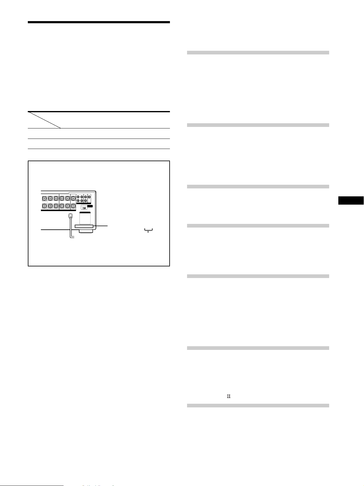
About area codes
The area code of the player you purchased is shown on the
lower portion of the rear panel (see the illustration below).
FRONT
REAR
SUB WOOFER
BA
LRL
Any differences in operation, according to the area code, are
clearly indicated in the text, for example, “Models of area
code AA only”.
REARFRONT CENTER
RL
SPEAKERS IMPEDANCE USE 4 – 16Ω
L
R
PRE OUT
4 Ω 8 Ω
AC OUTLET
CENTER
IMPEDANCE
SELECTOR
4-XXX-XXX-XX AA
Area code
TABLE OF CONTENTS
Hooking Up the Components 4
Unpacking 4
Antenna Hookups 5
Audio Component Hookups 6
Video Component Hookups 8
Digital Component Hookups 9
5.1CH Input Hookups 11
Other Hookups 12
Hooking Up and Setting Up the
Speaker System 15
Speaker System Hookup 16
Performing Initial Setup Operations 18
Multi Channel Surround Setup 19
Before You Use Your Receiver 23
Location of Parts and Basic
Operations 26
Front Panel Parts Description 26
Enjoying Surround Sound 31
Selecting a Sound Field 32
Understanding the Multi-Channel Surround
Displays 36
Customizing Sound Fields 38
GB
Conventions
• The instructions in this manual describe the controls on
the receiver. You can also use the controls on the
supplied remote if they have the same or similar names
as those on the receiver. For details on the use of your
remote, refer to the separate operating instructions
supplied with the remote.
• The following icon is used in this manual:
z Indicates hints and tips for making the task easier.
This receiver incorporates Dolby
* Digital and Pro Logic
Surround and the DTS** Digital Surround System.
Manufactured under license from Dolby Laboratories.
*
“Dolby”, “AC-3”, “Pro Logic” and the double-D symbol ; are
trademarks of Dolby Laboratories.
Confidential unpublished Works. © 1992-1997 Dolby Laboratories.
All rights reserved.
Manufactured under license from Digital Theater Systems, Inc. US
**
Pat. No. 5,451,942 and other worldwide patents issued and pending.
“DTS” and “DTS Digital Surround” are trademarks of Digital
Theater Systems, Inc. © 1996 Digital Theater Systems, Inc. All
rights reserved.
Receiving Broadcasts 43
Storing FM Stations Automatically
(AUTOBETICAL)*** 44
Direct Tuning 45
Automatic Tuning 45
Preset Tuning 46
Using the Radio Data System (RDS)*** 47
***Models of area code CED only.
Other Operations 50
Naming Preset Stations and Program Sources 51
Recording 51
Using the Sleep Timer 52
Adjustments Using the SET UP Button 53
CONTROL A1 Control System 54
Additional Information 56
Troubleshooting 56
Specifications 58
Glossary 61
Tables of Settings Using SUR, LEVEL, EQ, and SET
UP buttons 62
Index (Back cover)
3
GB

Hooking Up
Unpacking
the
Components
This chapter describes how to connect
various audio and video components
to the receiver. Be sure to read the
sections for the components you have
before you actually connect them to
the receiver.
Check that you received the following items with the
remote:
• FM wire antenna (1)
• AM loop antenna (1)
Models of area code U, CA only
• Audio/video/control S connecting cord (1)
• Control S connecting cord (1)
STR-DB940 only
• Remote commander RM-LJ304 (remote) (1)
• R6 (size-AA) batteries (3)
STR-DB840 only
• Models of area code CED only
– Remote commander RM-PP404 (remote) (1)
– R6 (size-AA) batteries (2)
• Models of other area codes
– Remote commander RM-LP204 (remote) (1)
– R6 (size-AA) batteries (3)
Inserting batteries into the remote
Insert batteries with the + and – properly oriented in the
battery compartment. When using the remote, point it at
the remote sensor
For details, refer to the operating instructions supplied
with your remote.
on the receiver.
z
When to replace batteries
Under normal conditions, the batteries should last for about
3 months (alkaline batteries) or 2 months (manganese batteries).
When the remote no longer operates the receiver, replace all
batteries with new ones.
Notes
• Do not leave the remote in an extremely hot or humid place.
• Do not use a new battery with an old one.
• Do not expose the remote sensor to direct sunlight or lighting
apparatuses. Doing so may cause a malfunction.
• If you don’t use the remote for an extended period of time,
remove the batteries to avoid possible damage from battery
leakage and corrosion.
• This remote is designed for use with alkaline batteries only. Do
not use a combination of different battery types.
Before you get started
• Turn off the power to all components before making
any connections.
• Do not connect the AC power cord until all of the
connections are completed.
• Be sure to make connections firmly to avoid hum and
noise.
• When connecting an audio/video cord, be sure to
match the color-coded pins to the appropriate jacks on
the components: yellow (video) to yellow; white (left,
audio) to white; and red (right, audio) to red.
GB
4
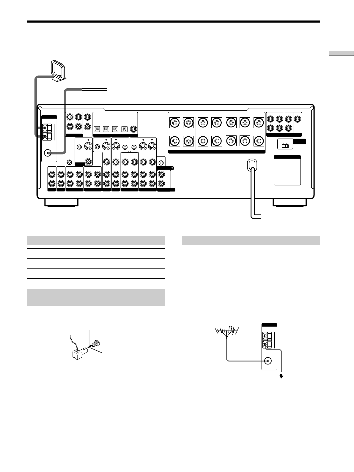
Antenna Hookups
ANTENNA
FM
75Ω
COAXIAL
L
R
PHONOINCD
AM loop antenna
(supplied)
AM
FRONT
5.1CH INPUT
U
SIGNAL
GND
U
IN
OUT
L
R
MD/DAT
REAR
CTRL S
IN
MONITOR
IN
CENTER
WOOFER
S-VIDEO
FM wire antenna
(supplied)
TV/SAT
MD/DAT
MD/DAT
OPTICAL
OPTICAL
SUB
OUT
VIDEO
OUT
TAPE
OPTICAL
OUT
CTRL S
STATUS IN
IN
IN
S-VIDEO
IN
VIDEO
AUDIO
IN
TV/SAT
IN
DIGITAL
S-VIDEO
IN
VIDEO
AUDIO
IN
DVD/LD
DVD/LD
OPTICAL
IN
CTRL S
OUT
OUT
VIDEO
AUDIO
OUT
VIDEO 2
DVD/LD
COAXIAL
IN
CTRL S
OUT
VIDEO
AUDIO
Hooking Up the Components
FRONT
REAR
SUB WOOFER
PRE OUT
4 Ω 8 Ω
AC OUTLET
CENTER
IMPEDANCE
SELECTOR
BA
REARFRONT CENTER
L
+
RLRL
RL
R
–
S-VIDEO
S-VIDEO
OUT
IN
IN
VIDEO
VIDEO
AUDIO
AUDIO
CONTROL A1
IN
OUT
IN
VIDEO 1
L
R
2ND AUDIO OUT
SPEAKERS IMPEDANCE USE 4 – 16Ω
Terminals for connecting the antennas
Connect the To the
AM loop antenna AM terminals
FM wire antenna FM 75Ω COAXIAL terminal
Assembling the supplied FM antenna
(Models of area code U,CA only)
The supplied FM wire antenna must be connected to the
supplied FM antenna adaptor.
FM
75Ω
COAXIAL
Notes on antenna hookups
• To prevent noise pickup, keep the AM loop antenna
away from the receiver and other components.
• Be sure to fully extend the FM wire antenna.
• After connecting the FM wire antenna, keep it as
horizontal as possible.
z
If you have poor FM reception
Use a 75-ohm coaxial cable (not supplied) to connect the receiver
to an outdoor FM antenna as shown below.
Outdoor FM antenna Receiver
Important
If you connect the receiver to an outdoor antenna, ground
it against lightning. To prevent a gas explosion, do not
connect the ground wire to a gas pipe.
ANTENNA
AM
U
FM
75Ω
COAXIAL
To ground
Ground wire
(not supplied)
Note
Do not use the U SIGNAL GND terminal for grounding the
receiver.
GB
5
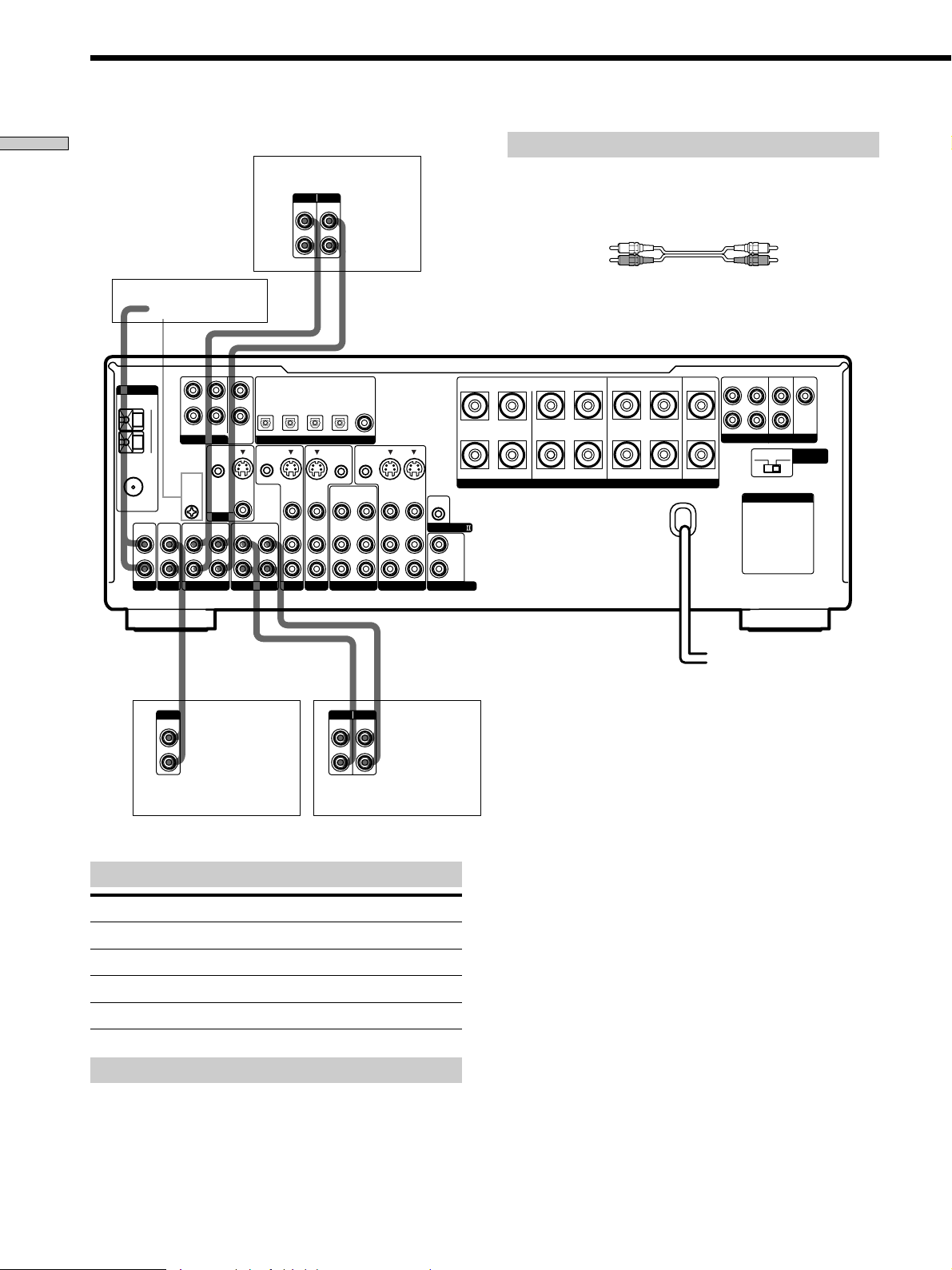
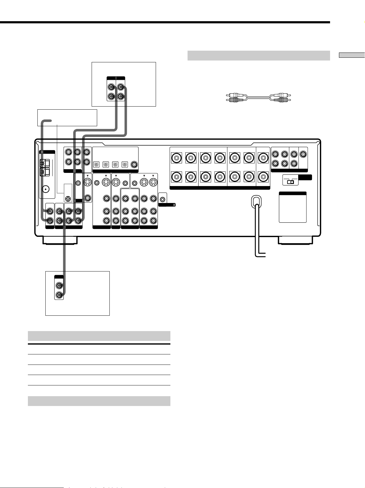
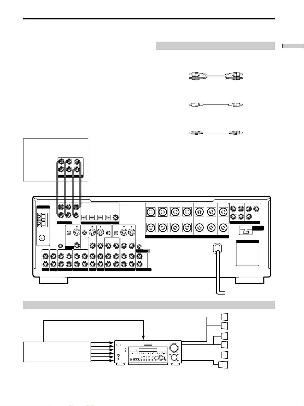
Audio Component Hookups
Hooking Up the Components
STR-DB940
Turntable
ANTENNA
FM
75Ω
COAXIAL
L
R
PHONOINCD
AM
U
IN
L
R
FRONT
REAR
5.1CH INPUT
CTRL S
SIGNAL
GND
U
MONITOR
OUT
MD/DAT
CENTER
SUB
WOOFER
IN
S-VIDEO
VIDEO
IN
Required cords
MD/DAT deck
INPUT OUTPUT
LINE
LINE
L
R
ç
Audio cords (not supplied)
When connecting a cord, be sure to match the color-coded pins to
the appropriate jacks on the components.
White (L) White (L)
Red (R) Red (R)
ç
INOUT
DVD/LD
TV/SAT
IN
IN
IN
OPTICAL
IN
DIGITAL
S-VIDEO
IN
VIDEO
AUDIO
IN
DVD/LD
DVD/LD
OPTICAL
IN
CTRL S
OUT
OUT
VIDEO
AUDIO
OUT
VIDEO 2
COAXIAL
IN
CTRL S
OUT
VIDEO
AUDIO
FRONT
REAR
SUB WOOFER
BA
REARFRONT CENTER
L
CENTER
+
RLRL
RL
–
S-VIDEO
S-VIDEO
OUT
IN
IN
VIDEO
AUDIO
OUT
VIDEO 1
IN
VIDEO
AUDIO
IN
CONTROL A1
L
R
2ND AUDIO OUT
SPEAKERS IMPEDANCE USE 4 – 16Ω
R
PRE OUT
4 Ω 8 Ω
AC OUTLET
IMPEDANCE
SELECTOR
MD/DAT
MD/DAT
OPTICAL
OPTICAL
OUT
CTRL S
STATUS IN
S-VIDEO
OUT
VIDEO
AUDIO
IN
OUT
TV/SAT
TAPE
ç
ç
OUTPUT
LINE
L
R
CD player
Jacks for connecting audio components
Connect a To the
Turntable PHONO jacks
CD player CD jacks
Tape deck TAPE jacks
MD deck or DAT deck MD/DAT jacks
Note on audio component hookups
If your turntable has a ground wire, connect it to the
U SIGNAL GND terminal on the receiver.
INPUT OUTPUT
LINE
LINE
L
R
Tape deck
GB
6
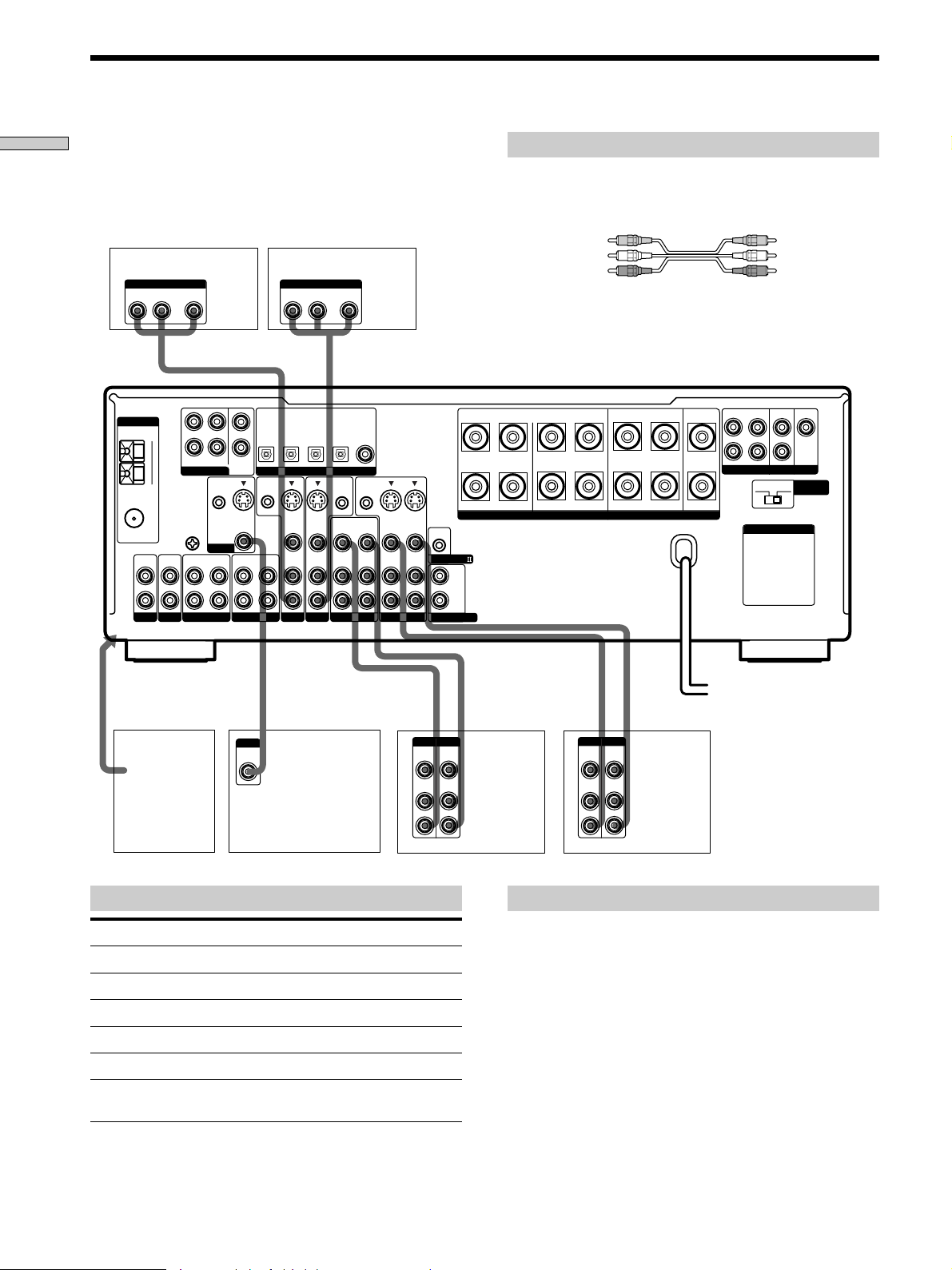
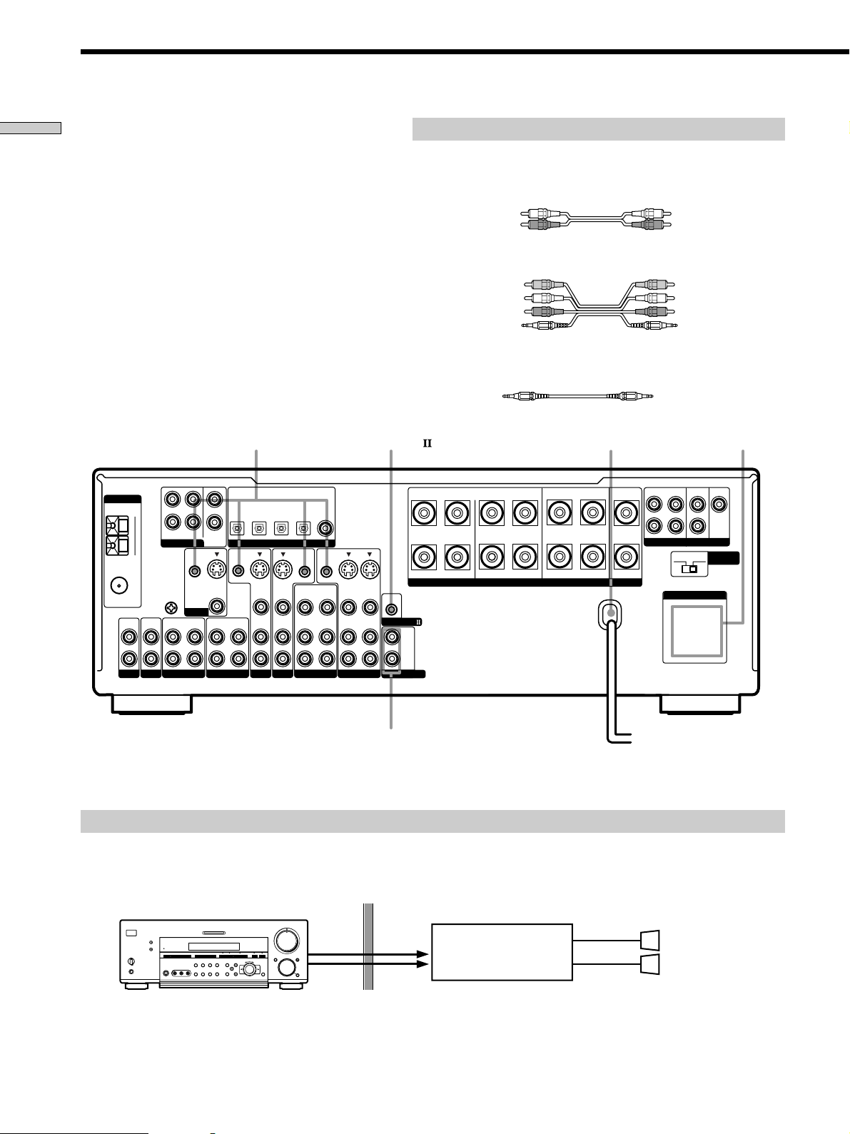
STR-DB840
MD/Tape deck
INPUT OUTPUT
LINE
LINE
L
R
ç
Required cords
Audio cords (not supplied)
When connecting a cord, be sure to match the color-coded pins to
the appropriate jacks on the components.
White (L) White (L)
Red (R) Red (R)
Hooking Up the Components
ANTENNA
FM
75Ω
COAXIAL
L
R
PHONOINCD
Turntable
AM
U
IN
OUTPUT
LINE
L
R
FRONT
REAR
5.1CH INPUT
CTRL S
SIGNAL
GND
U
MONITOR
OUT
MD/TAPE
L
R
ç
INOUT
TV/SAT
MD/TAPE
MD/TAPE
OPTICAL
OPTICAL
OPTICAL
IN
OUT
CENTER
SUB
WOOFER
IN
S-VIDEO
OUT
VIDEO
IN
CTRL S
STATUS IN
TV/SAT
S-VIDEO
IN
VIDEO
AUDIO
IN
DIGITAL
S-VIDEO
VIDEO
AUDIO
DVD/LD
DVD/LD
DVD/LD
COAXIAL
OPTICAL
IN
IN
IN
BA
REARFRONT CENTER
FRONT
REAR
L
SUB WOOFER
CENTER
+
RLRL
CTRL S
CTRL S
OUT
OUT
S-VIDEO
VIDEO 2
IN
VIDEO
AUDIO
IN
OUT
VIDEO
AUDIO
OUT
VIDEO 1
IN
OUT
VIDEO
AUDIO
IN
OUT
S-VIDEO
IN
VIDEO
AUDIO
IN
–
SPEAKERS IMPEDANCE USE 4 – 16Ω
CONTROL A1
L
R
RL
R
PRE OUT
4 Ω 8 Ω
AC OUTLET
IMPEDANCE
SELECTOR
CD player
Jacks for connecting audio components
Connect a To the
Turntable PHONO jacks
CD player CD jacks
MD deck or tape deck MD/TAPE jacks
Note on audio component hookups
If your turntable has a ground wire, connect it to the
U SIGNAL GND terminal on the receiver.
GB
7
Video Component Hookups
Hooking Up the Components
TV or satellite tuner
OUTPUT
AUDIO OUT VIDEO
L
R
ANTENNA
FM
75Ω
COAXIAL
OUT
L
AM
FRONT
5.1CH INPUT
U
SIGNAL
CENTER
R
SUB
REAR
WOOFER
CTRL S
IN
GND
S-VIDEO
U
OUT
MD/DAT
MONITOR
IN
IN
L
R
PHONOINCD
OUT
VIDEO
OUT
DVD or LD player
AUDIO OUT VIDEO
R
MD/DAT
MD/DAT
OPTICAL
OPTICAL
IN
OUT
CTRL S
STATUS IN
S-VIDEO
IN
VIDEO
AUDIO
IN
IN
TAPE
TV/SAT
OUTPUT
L
TV/SAT
OPTICAL
IN
DIGITAL
S-VIDEO
IN
VIDEO
AUDIO
IN
DVD/LD
DVD/LD
OPTICAL
CTRL S
OUT
OUT
VIDEO
AUDIO
IN
OUT
OUT
VIDEO 2
DVD/LD
COAXIAL
IN
CTRL S
OUT
VIDEO
AUDIO
Required cords
Audio/video cords (not supplied)
When connecting a cord, be sure to match the color-coded pins to
the appropriate jacks on the components.
Yellow (video) Yellow (video)
White (L/audio) White (L/audio)
Red (R/audio) Red (R/audio)
Video cord for connecting a TV monitor
You can use the video cord of the supplied audio/video/control
S cord. (Models of area code U, CA only. See page 12 for details).
FRONT
REAR
SUB WOOFER
PRE OUT
4 Ω 8 Ω
AC OUTLET
CENTER
IMPEDANCE
SELECTOR
BA
REARFRONT CENTER
L
+
RLRL
RL
R
–
S-VIDEO
S-VIDEO
OUT
IN
IN
VIDEO
AUDIO
OUT
VIDEO 1
IN
VIDEO
AUDIO
IN
CONTROL A1
L
R
2ND AUDIO OUT
SPEAKERS IMPEDANCE USE 4 – 16Ω
To the front panel
Camcorder
or video
game
INPUT
VIDEO
IN
VIDEO
AUDIO
IN
IN
TV monitor
Jacks for connecting video components
Connect a To the
TV or satellite tuner TV/SAT jacks
VCR VIDEO 1 jacks
Additional VCR VIDEO 2 jacks
DVD or LD player DVD/LD jacks
TV monitor
Camcorder or video game VIDEO 3 INPUT jacks on the
1)
For STR-DB940, you can display the SURROUND, LEVEL,
EQUALIZER parameters by pressing the ON SCREEN button
on the remote.
1)
MONITOR VIDEO OUT jack
front panel
Ç
OUTPUTINPUT
VIDEO
OUT
AUDIO
OUT
INOUT
Ç
INOUT
Ç
Ç
OUTPUTINPUT
VIDEO
VIDEO
IN
OUT
AUDIO
AUDIO
OUT
IN
L
R
VCR
Note on video component hookups
You can connect your TV’s audio output jacks to the TV/
SAT AUDIO IN jacks on the receiver and apply sound
effects to the audio from the TV. In this case, do not
connect the TV’s video output jack to the TV/SAT VIDEO
IN jack on the receiver. If you are connecting a separate
TV tuner (or satellite tuner), connect both the audio and
video output jacks to the receiver as shown above.
z
When using the S-video jacks instead of the video jacks
Your monitor must also be connected via an S-video jack. S-video
signals are on a separate bus from the video signals and will not
be output through the video jacks.
L
R
VCR
GB
8
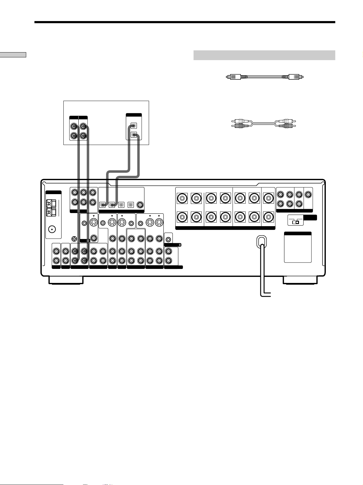
Digital Component Hookups
Connect the digital output jacks of your DVD player and
satellite tuner (etc.) to the receiver’s digital input jacks to
bring the multi channel surround sound of a movie
theater into your home. To enjoy full effect of multi
channel surround sound, five speakers (two front
speakers, two rear speakers, and a center speaker) and a
sub woofer are required. You can also connect an LD
player with an RF OUT jack via an RF demodulator, like
the Sony MOD-RF1 (not supplied).
ANTENNA
FM
75Ω
COAXIAL
L
R
PHONOINCD
TV or satellite tuner
OUTPUT
VIDEO
OUT
AUDIO
OUT
L
R
L
GND
U
OUT
MD/DAT
R
REAR
CTRL S
IN
MONITOR
IN
CENTER
SUB
WOOFER
S-VIDEO
OUT
VIDEO
OUT
TAPE
AM
FRONT
5.1CH INPUT
U
SIGNAL
IN
MD/DAT
OPTICAL
OUT
CTRL S
STATUS IN
IN
MD/DAT
OPTICAL
IN
S-VIDEO
IN
VIDEO
AUDIO
IN
TV/SAT
OUTPUT
DIGITAL
OPTICAL
DIGITAL
DVD/LD
DVD or LD player (etc.)*
OUTPUT
DIGITAL
OPTICAL
IN
VIDEO
IN
DVD/LD
DVD/LD
COAXIAL
OPTICAL
IN
IN
CTRL S
CTRL S
OUT
OUT
S-VIDEO
OUT
VIDEO 2
IN
VIDEO
AUDIO
IN
OUT
VIDEO
AUDIO
OUT
VIDEO 1
IN
OUT
VIDEO
AUDIO
TV/SAT
OPTICAL
S-VIDEO
AUDIO
OUTPUT
DIGITAL
COAXIAL
S-VIDEO
IN
VIDEO
AUDIO
IN
+
–
CONTROL A1
2ND AUDIO OUT
Required cords
Optical digital cords (not supplied)
Black Black
Coaxial digital cord (not supplied)
Yellow Yellow
Audio/video cords (not supplied)
When connecting a cord, be sure to match the color-coded pins to
the appropriate jacks on the components.
Yellow (video) Yellow (video)
White (L/audio) White (L/audio)
OUTPUT
VIDEO
AUDIO
RLRL
L
R
Red (R/audio) Red (R/audio)
OUT
OUT
L
R
BA
SPEAKERS IMPEDANCE USE 4 – 16Ω
REARFRONT CENTER
RL
FRONT
REAR
L
R
PRE OUT
4 Ω 8 Ω
AC OUTLET
SUB WOOFER
CENTER
IMPEDANCE
SELECTOR
Hooking Up the Components
Make either coaxial or optical connections. We recommend making coaxial connections instead of optical connections.
*
Example of LD player connected via an RF demodulator
Please note that you cannot connect an LD player’s AC-3 RF OUT jack directly to this unit’s digital input jacks. You must
first convert the RF signal to either an optical or coaxial digital signal. Connect the LD player to the RF demodulator, then
connect the RF demodulator’s optical or coaxial digital output to this unit’s OPTICAL or COAXIAL DVD/LD IN jack.
Refer to the instruction manual supplied with your RF Demodulator for details on AC-3 RF hookups.
DVD/LD
?/1
•
•
•
•
VIDEO IN
–+ –+
5
•
•
•
46
•
•
•
3
•
•
•
2
•
•
•
1
•
•
•
–
+
0
+
–
VIDEO OUT
AC-3 RF
OUT
DIGITAL
DIGITAL
DVD/LD IN
DVD/LD IN
(COAXIAL)
RF demodulatorLD player
(COAXIAL)
or (OPTICAL)
(OPTICAL)
Note
When making connections as shown above, be sure to set INPUT MODE (5 on page 27) manually. This unit may not operate correctly if
INPUT MODE is set to “AUTO.”
9
•
•
•
•
•
•
7
•
•
•
8
•
•
•
9
•
•
•
10
GB
Digital Component Hookups
Hooking Up the Components
Connect the digital output jacks of your MD or DAT deck
to the receiver’s digital input jack and connect the digital
input jacks of your MD or DAT deck to the receiver’s
digital output jack. These connections allow you to make
digital recordings of a CDs played back through your
DVD (or LD player) and satellite broadcasts.
MD or DAT deck
INPUT OUTPUT
LINE
LINE
L
R
ç
ANTENNA
FM
75Ω
COAXIAL
L
R
PHONOINCD
AM
U
IN
L
R
FRONT
REAR
5.1CH INPUT
CTRL S
SIGNAL
GND
U
MONITOR
OUT
MD/DAT
CENTER
WOOFER
IN
IN
ç
INOUT
SUB
STATUS IN
S-VIDEO
OUT
VIDEO
OUT
TAPE
MD/DAT
OPTICAL
OUT
CTRL S
Required cords
Optical digital cords (not supplied)
Black Black
Audio cords (not supplied)
When connecting a cord, be sure to match the color-coded pins to
the appropriate jacks on the components.
DIGITAL
OPTICAL
IN
OUT
White (L) White (L)
Red (R) Red (R)
ç
ç
INOUT
DVD/LD
TV/SAT
IN
VIDEO
AUDIO
IN
IN
OPTICAL
IN
DIGITAL
S-VIDEO
IN
VIDEO
AUDIO
IN
DVD/LD
DVD/LD
OPTICAL
IN
CTRL S
OUT
OUT
VIDEO
AUDIO
OUT
VIDEO 2
COAXIAL
IN
CTRL S
OUT
VIDEO
AUDIO
FRONT
REAR
SUB WOOFER
BA
REARFRONT CENTER
L
CENTER
+
RLRL
RL
–
S-VIDEO
S-VIDEO
OUT
IN
IN
VIDEO
VIDEO
AUDIO
AUDIO
CONTROL A1
IN
OUT
IN
VIDEO 1
L
R
2ND AUDIO OUT
SPEAKERS IMPEDANCE USE 4 – 16Ω
R
PRE OUT
4 Ω 8 Ω
AC OUTLET
IMPEDANCE
SELECTOR
MD/DAT
OPTICAL
S-VIDEO
IN
TV/SAT
Notes
• Please note that you cannot make a digital recording of a digital multi channel surround signal.
• To make a digital recording from your CD player, connect the CD player’s digital output directly to the digital input on your MD or DAT
deck. Refer to the instructions supplied with your CD player and MD or DAT deck for details.
• The DVD/LD IN OPTICAL and COAXIAL jacks are compatible with 96 kHz, 48 kHz, 44.1 kHz and 32 kHz sampling frequencies. The
other OPTICAL jacks are compatible with 48 kHz, 44.1 kHz and 32 kHz sampling frequencies.
• It is not possible to record analog signals to TAPE and VIDEO with only digital connections. To record analog signals, make analog
connections. To record digital signals, make digital connections.
• Input signals with 96 kHz sampling frequencies to the DVD/LD IN OPTICAL or COAXIAL jacks. Using other jacks may result in
intermittent sound.
GB
10
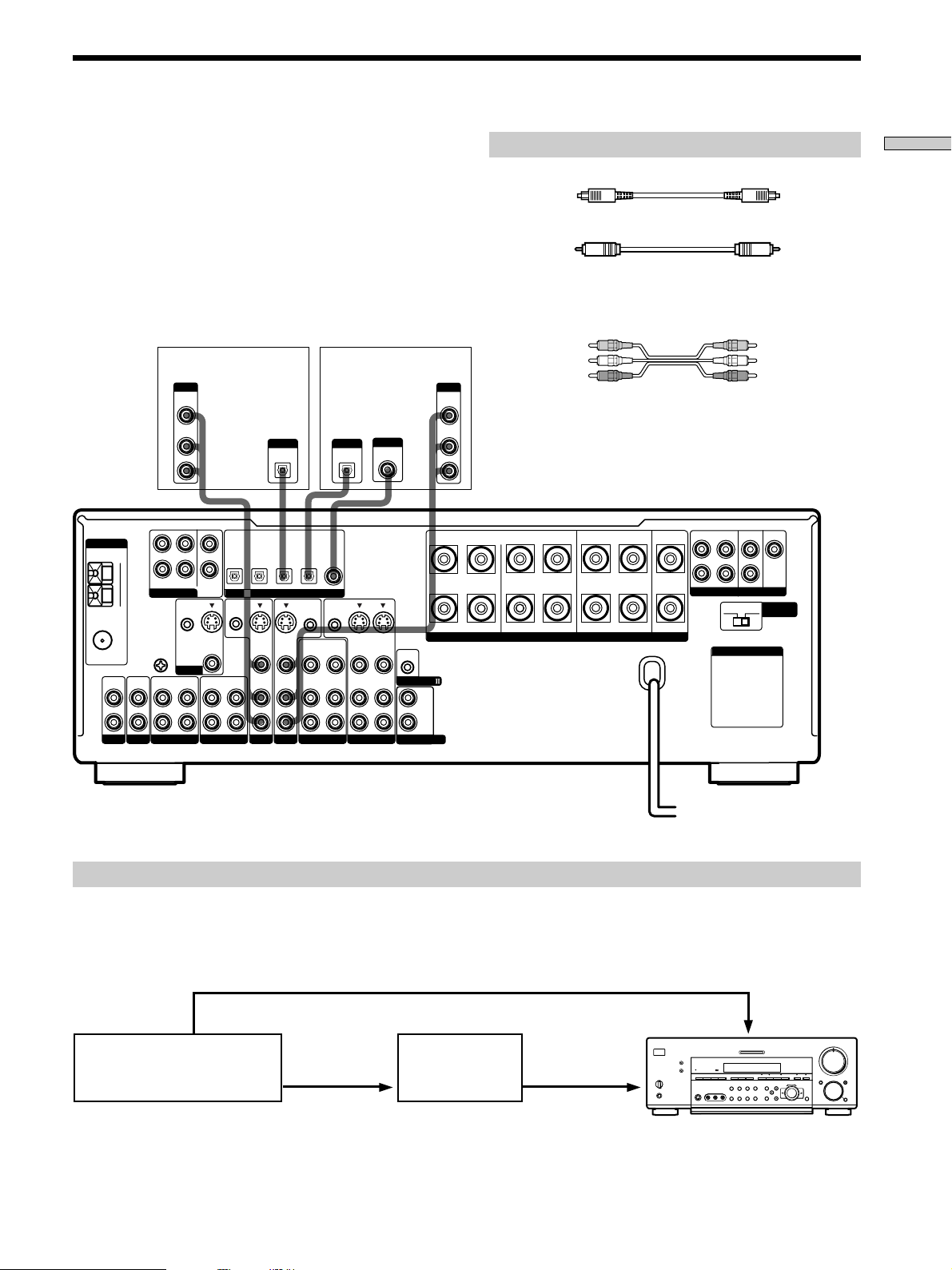
5.1CH Input Hookups
Although this receiver incorporates a multi channel
decoder, it is also equipped with 5.1CH INPUT jacks.
These connections allow you to enjoy multichannel
software encoded in formats other than Dolby Digital
(AC-3) and DTS. If your DVD player is equipped with
5.1CH OUTPUT jacks, you can connect them directly to
this unit to enjoy the sound of the DVD player’s multi
channel decoder. Alternatively, the 5.1CH INPUT jacks
can be used to connect an external multi channel decoder.
To fully enjoy multi channel surround sound, you will
need five speakers (two front speakers, two rear speakers,
and a center speaker) and a sub woofer. Refer to the
instruction manual supplied with your DVD player, multi
channel decoder, etc., for details on the 5.1 channel input
hookups.
DVD player,
Multichannel decoder, etc.
L
CENTER
R
FRONT
REAR
SUB WOOFER
5.1CH OUTPUT
Required cords
Audio cords (not supplied)
Two for the 5.1CH INPUT FRONT and REAR jacks
White (L) White (L)
Red (R) Red (R)
Monaural audio cords (not supplied)
Two for the 5.1CH INPUT CENTER and SUB WOOFER jacks
Black Black
Video cord (not supplied)
One for the DVD/LD VIDEO IN jacks (etc.)
Yellow Yellow
Note
When using the connections described below, adjust the level of
your surround speakers and sub woofer from the DVD player or
multichannel decoder.
Hooking Up the Components
ANTENNA
FM
75Ω
COAXIAL
L
R
PHONOINCD
L
AM
R
FRONT
REAR
5.1CH INPUT
SIGNAL
GND
CTRL S
U
U
OUT
MD/DAT
MONITOR
IN
MD/DAT
OPTICAL
CENTER
SUB
WOOFER
CTRL S
STATUS IN
IN
S-VIDEO
OUT
VIDEO
OUT
IN
TAPE
OPTICAL
OPTICAL
IN
OUT
DIGITAL
S-VIDEO
S-VIDEO
IN
VIDEO
AUDIO
IN
IN
TV/SAT
DVD/LD
TV/SAT
MD/DAT
IN
IN
VIDEO
AUDIO
IN
DVD/LD
OPTICAL
IN
CTRL S
OUT
OUT
VIDEO
AUDIO
OUT
VIDEO 2
DVD/LD
COAXIAL
IN
CTRL S
OUT
VIDEO
AUDIO
BA
+
RLRL
–
S-VIDEO
S-VIDEO
OUT
IN
IN
VIDEO
VIDEO
AUDIO
AUDIO
CONTROL A1
IN
OUT
IN
VIDEO 1
L
R
2ND AUDIO OUT
Example of a DVD player hookup using the 5.1CH INPUT jacks
VIDEO OUT
5.1 CH INPUT
DVD player
Note
See page 16 for details on speaker system hookup.
?/1
•
•
•
•
DVD/LD
IN VIDEO etc.
–+ –+
–
+
5
•
•
•
•
•
•
46
•
•
•
•
•
•
3
7
•
•
•
•
2
•
•
•
1
9
•
•
•
•
•
•
0
10
+
–
REARFRONT CENTER
RL
SPEAKERS IMPEDANCE USE 4 – 16Ω
SPEAKERS
FRONT
•
•
8
•
•
SPEAKERS
•
REAR/CENTER
SUB WOOFER
FRONT
REAR
SUB WOOFER
PRE OUT
4 Ω 8 Ω
CENTER
IMPEDANCE
SELECTOR
L
R
AC OUTLET
Front Speaker (L)
Front Speaker (R)
Rear Speaker (L)
Rear Speaker (R)
Center Speaker
Active Woofer
11
GB
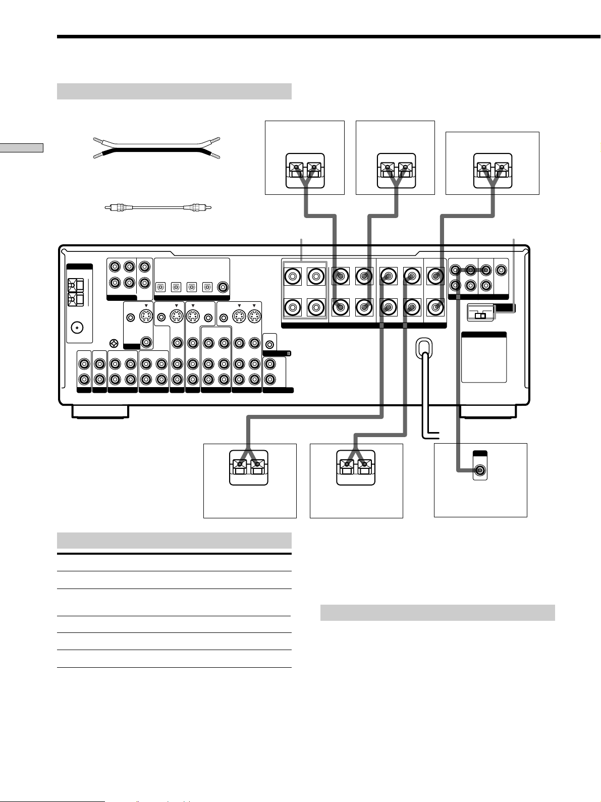
Other Hookups
Hooking Up the Components
CTRL S (STATUS) IN/OUT** CONTROL A1
ANTENNA
FM
75Ω
COAXIAL
L
R
PHONOINCD
AM
U
IN
L
R
FRONT
REAR
5.1CH INPUT
CTRL S
SIGNAL
GND
U
MONITOR
OUT
MD/DAT
CENTER
SUB
WOOFER
IN
S-VIDEO
VIDEO
IN
Required cords
Audio cords (not supplied)
When connecting a cord, be sure to match the color-coded pins to the
appropriate jacks on the components.
White (L) White (L)
Red (R) Red (R)
Audio/video/control S connecting cord (1)**
Yellow (video) A
White (L/audio) B
Red (R/audio) C
Black (control S) D
Control S connecting cord (1)**
Black E Black E
AC power cord
DVD/LD
TV/SAT
IN
IN
IN
OPTICAL
IN
DIGITAL
S-VIDEO
IN
VIDEO
AUDIO
IN
DVD/LD
DVD/LD
OPTICAL
IN
CTRL S
OUT
OUT
VIDEO
AUDIO
OUT
VIDEO 2
COAXIAL
CTRL S
VIDEO
AUDIO
IN
BA
REARFRONT CENTER
+
RLRL
S-VIDEO
IN
VIDEO
AUDIO
IN
–
SPEAKERS IMPEDANCE USE 4 – 16Ω
CONTROL A1
L
R
2ND AUDIO OUT
OUT
S-VIDEO
OUT
IN
VIDEO
AUDIO
OUT
IN
VIDEO 1
RL
MD/DAT
MD/DAT
OPTICAL
OPTICAL
OUT
CTRL S
STATUS IN
S-VIDEO
OUT
VIDEO
AUDIO
IN
OUT
TAPE
TV/SAT
Yellow (video) A
White (L/audio) B
Red (R/audio) C
Black (control S) D
AC OUTLET
FRONT
REAR
SUB WOOFER
L
R
PRE OUT
4 Ω 8 Ω
AC OUTLET
CENTER
IMPEDANCE
SELECTOR
*
2ND AUDIO OUT
(STR-DB940 only)
The configuration, shape, and number of AC outlets on the rear panel varies according to the model and country to which the receiver is shipped.
*
To a wall outlet
b
** Models of area code U, CA only.
Example of a sub room hookup using the 2ND AUDIO OUT jacks (STR-DB940 only)
You can use the 2ND AUDIO OUT jacks to output the audio signal of the selected component to a stereo amplifier located
in another room. Use MODE and FUNCTION (4 on pages 26 and 27) to switch the audio signal output to the sub room.
Main room
5
•
•
•
•
•
•
46
•
•
•
•
•
?/1
•
•
•
•
–+ –+
–
+
•
3
7
AUDIO
•
•
•
•
•
•
2
8
•
•
•
•
•
•
OUT
1
9
•
•
•
•
•
•
0
10
+
–
Note
This function is not available when 5.1CH INPUT is selected.
GB
12
AUDIO
IN
Sub room
Stereo amplifier
SPEAKERS
R
L
Speaker (L)
Speaker (R)
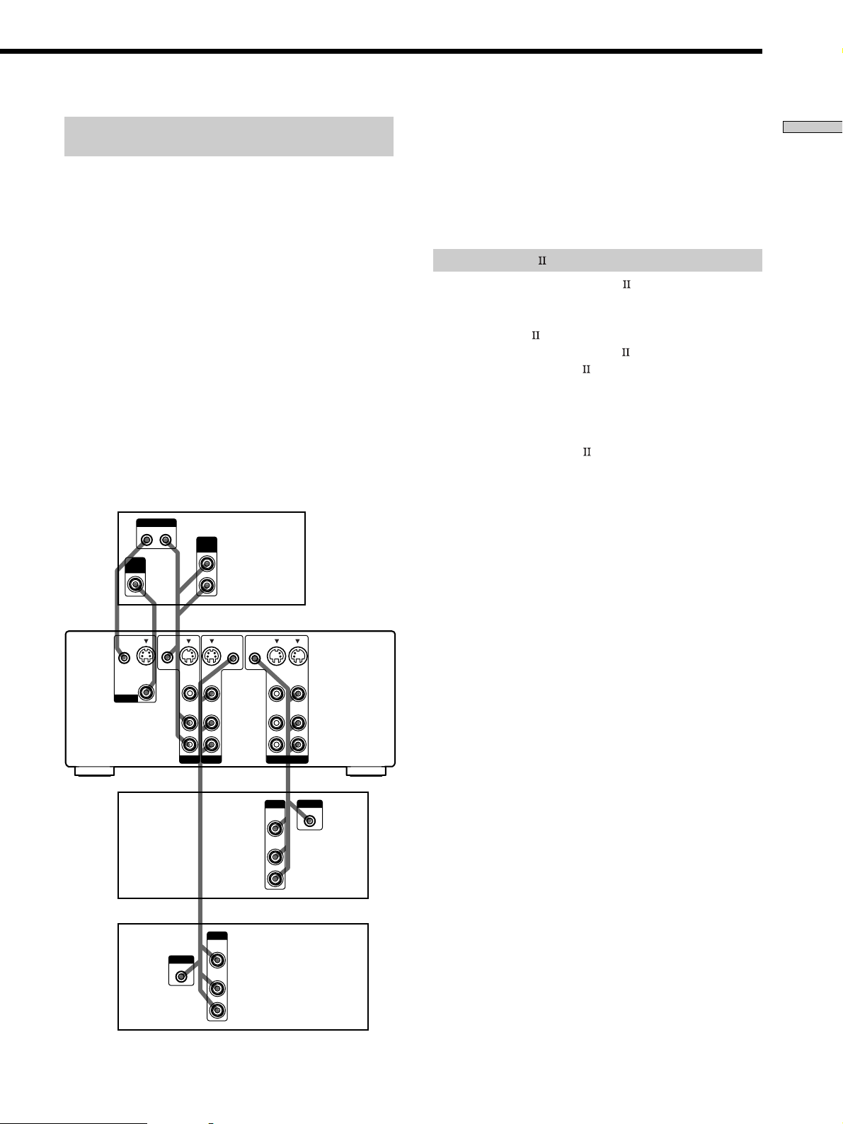
S-LINK CONTROL S hookup
(Models of area code U,CA only)
If you have a S-LINK CONTROL S-compatible Sony TV,
satellite tuner, monitor, DVD player or VCR, use an
audio/video/control S connecting cord (supplied) or a
control S connecting cord (supplied) to connect the CTRL
S (STATUS) IN (for TV, satellite tuner, or monitor) or OUT
(for VCR, etc.) jack on the receiver to the appropriate SLINK jack on the respective component. Refer to the
operating instructions supplied with your TV, satellite
tuner, monitor, VCR, etc., for details.
The following illustration is an example of S-LINK
CONTROL S hookups between the receiver, a TV, a VCR,
and a DVD player. When your TV is connected to the
receiver as shown below, the TV input mode will change
to video input whenever you turn on the receiver. When
you connect the receiver as shown below, input mode of
the receiver changes to VIDEO 1 or DVD/LD whenever
you play your VCR or DVD.
The following connections also change the input mode of
the receiver to TV whenever you operate your TV.
TV
Receiver
VIDEO
CTRL S
IN
MONITOR
IN
S-LINK
OUT IN
A
S-VIDEO
OUT
VIDEO
CTRL S
STATUS IN
DE
S-VIDEO
****
VIDEO
AUDIO
AUDIO
OUT
B
C
CTRL S
CTRL S
OUT
OUT
S-VIDEO
IN
IN
VIDEO
AUDIO
IN
IN
S-VIDEO
OUT
VIDEO
AUDIO
OUT
S-VIDEO
IN
VIDEO
AUDIO
IN
* Audio/video/control S connecting cord (Pull the video cord away
from the supplied audio/video/control S cable for connection A.)
** Control S connecting cord
Note
Refer to the instructions supplied with your TV for details
regarding the operations you can control from your TV.
CONTROL A1 hookup
• If you have a CONTROL A1 compatible Sony
CD player, tape deck, or MD deck
Use a CONTROL A1 cord (not supplied) to connect the
CONTROL A1
MD deck to the CONTROL A1
Refer to “CONTROL A1
and the operating instructions supplied with your CD
player, tape deck, or MD deck for details.
Note
If you make CONTROL A1 connections from the receiver to
an MD deck that is also connected to a computer, do not
operate the receiver while using the “Sony MD Editor”
software. This may cause a malfunction.
• If you have a Sony CD changer with a
COMMAND MODE selector
If your CD changer’s COMMAND MODE selector can
be set to CD 1, CD 2, or CD 3, be sure to set the
command mode to “CD 1” and connect the changer to
the CD jacks on the receiver.
If, however, you have a Sony CD changer with VIDEO
OUT jacks, set the command mode to “CD 2” and
connect the changer to the VIDEO 2 jacks on the
receiver.
jack on the CD player, tape deck, or
jack on the receiver.
Control System” on page 54
Hooking Up the Components
VCR 1
DVD
player
S-LINK
IN
TV/SAT
DVD/LD
*
OUTPUT
VIDEO
OUT
AUDIO
OUT
VIDEO 1
OUTPUT
VIDEO
OUT
AUDIO
OUT
*
S-LINK
IN
13
GB

Other Hookups
Hooking Up the Components
Connecting the AC power cord
Before connecting the AC power cord of this receiver to a
wall outlet:
• Connect the speaker system to the receiver (see page
16).
• Turn the MASTER VOLUME control to the leftmost
position (0).
Connect the AC power cord(s) of your audio/video
components to a wall outlet.
If you connect other audio/video components to the AC
OUTLET(s) on the receiver, the receiver will supply power
to the connected component(s), allowing you to turn the
whole system on or off when you turn the receiver on or
off.
Caution
Make sure that the total power consumption of the component(s)
connected to the receiver’s AC OUTLET(s) does not exceed the
wattage stated on the rear panel. Do not connect high-wattage
electrical home appliances such as electric irons, fans, or TVs to
this outlet.
Note
If the AC power cord is disconnected for about two weeks, the
receiver’s entire memory will be cleared and the demonstration
will start.
14
GB
Hooking Up
and Setting Up
the Speaker
SET UP
?/1
•
•
•
•
–+ –+
–
+
Cursor buttons
46
•
•
•
3
•
•
•
2
•
•
•
1
•
•
•
0
+
–
5
•
•
•
•
•
•
•
•
•
7
•
•
•
8
•
•
•
9
•
•
•
10
System
This chapter describes how to hook
up your speaker system to the
receiver, how to position each speaker,
and how to set up your speakers to
enjoy multi channel surround sound.
Hooking Up and Setting Up the Speaker System
Jog dial
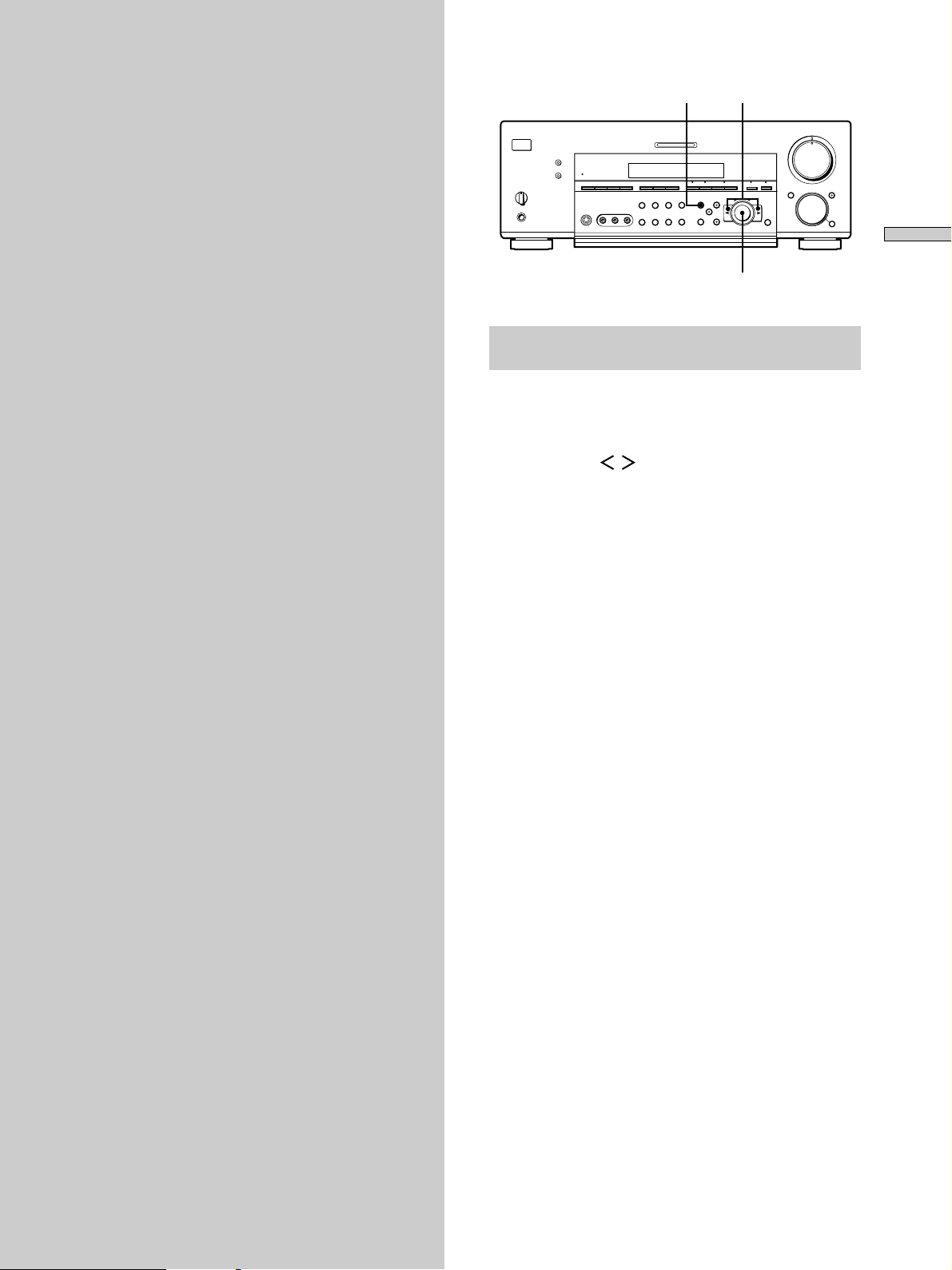
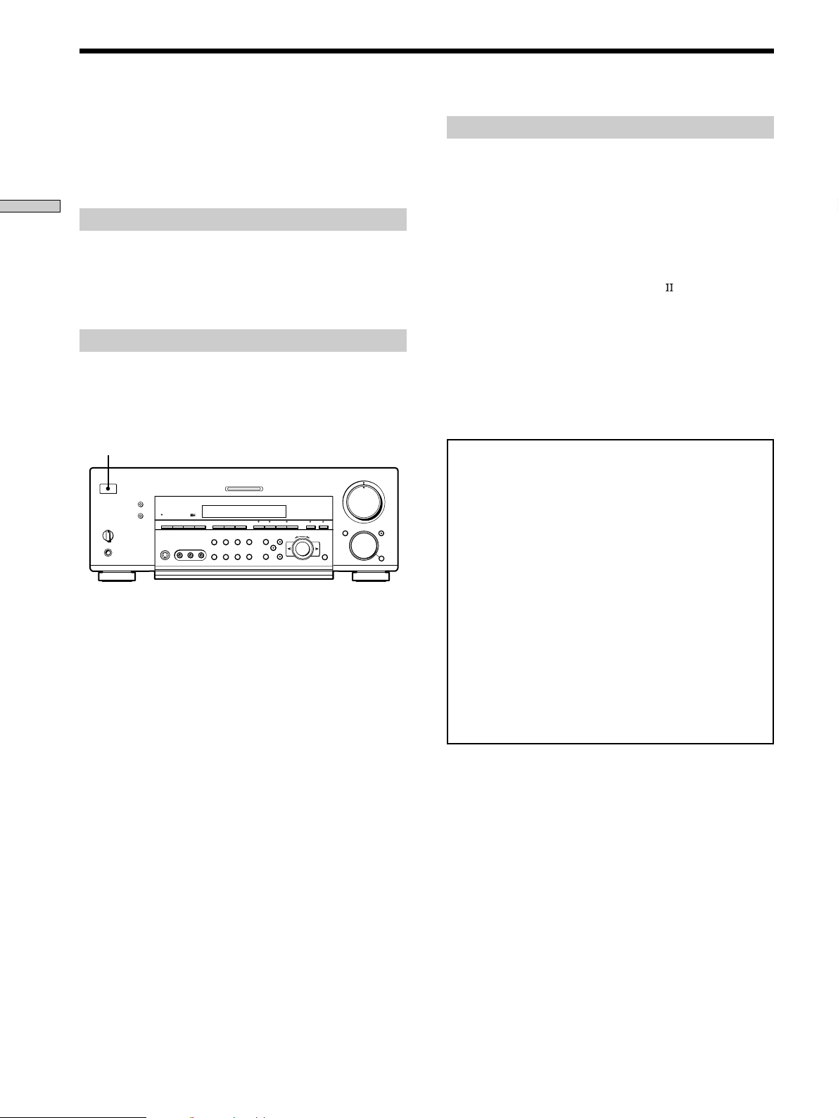
Brief descriptions of buttons and control
used to set up the speaker system
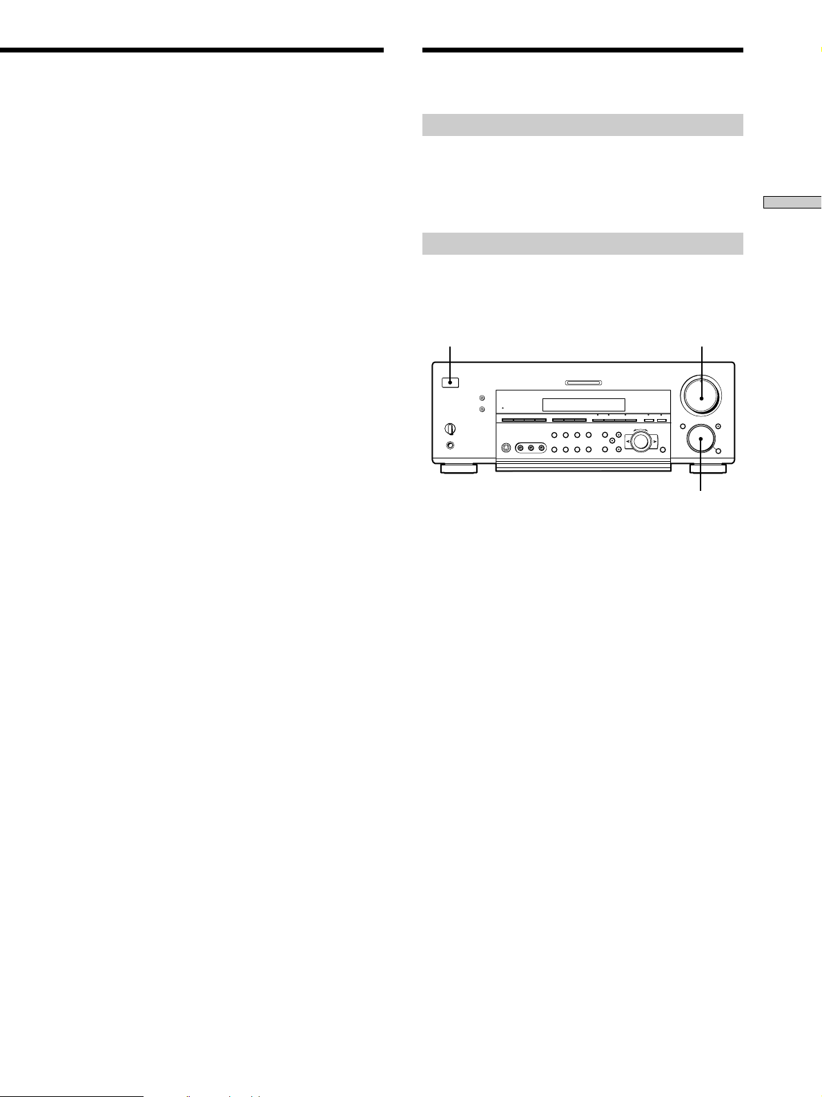
SET UP button: Press to enter the setup mode when
specifying speaker types and distances.
Cursor buttons ( / ): Use to select parameters after
pressing the SET UP button.
Jog dial: Use to adjust the setting of each parameter.
15
GB
Speaker System Hookup
Required cords
Speaker cords (not supplied)
One for each front, rear, and center speaker
(+) (+)
Hooking Up and Setting Up the Speaker System
(–) (–)
Monaural audio cord (not supplied)
One for an active sub woofer
Black Black
DVD/LD
TV/SAT
ANTENNA
FM
75Ω
COAXIAL
L
R
PHONOINCD
MD/DAT
CTRL S
IN
IN
CENTER
SUB
WOOFER
S-VIDEO
OUT
VIDEO
OUT
TAPE
MD/DAT
OPTICAL
OUT
CTRL S
STATUS IN
IN
OPTICAL
S-VIDEO
VIDEO
AUDIO
TV/SAT
L
AM
R
FRONT
REAR
5.1CH INPUT
U
SIGNAL
GND
U
OUT
MD/DAT
MONITOR
IN
IN
IN
IN
OPTICAL
IN
DIGITAL
S-VIDEO
IN
VIDEO
AUDIO
IN
DVD/LD
DVD/LD
OPTICAL
IN
CTRL S
OUT
OUT
VIDEO
AUDIO
OUT
VIDEO 2
COAXIAL
IN
CTRL S
OUT
VIDEO
AUDIO
S-VIDEO
OUT
IN
VIDEO
AUDIO
OUT
IN
VIDEO 1
Front speaker (R) Front speaker (L)
S-VIDEO
IN
VIDEO
AUDIO
IN
}]
FRONT
SPEAKERS B
BA
+
RLRL
–
CONTROL A1
L
R
2ND AUDIO OUT
}
SPEAKERS IMPEDANCE USE 4 – 16Ω
REARFRONT CENTER
RL
]
Center speaker
}
FRONT
REAR
SUB WOOFER
L
R
PRE OUT
4 Ω 8 Ω
AC OUTLET
IMPEDANCE
SELECTOR
CENTER
IMPEDANCE
SELECTOR
]
}]
Terminals for connecting the speakers
Connect the To the
Front speakers (8 or 4* ohm) SPEAKERS FRONT A terminals
Additional pair of front
speakers (8 or 4* ohm)
Rear speakers (8 or 4* ohm) SPEAKERS REAR terminals
Center speaker (8 or 4* ohm) SPEAKERS CENTER terminals
Active sub woofer SUB WOOFER PRE OUT**
* See “Speaker impedance” on the next page.
** You can connect an active sub woofer to either of the two jacks. The
remaining jack can be used to connect a second active sub woofer.
SPEAKERS FRONT B terminals
INPUT
AUDIO
}
]
IN
Active sub wooferRear speaker (R) Rear speaker (L)
z
To connect certain speakers to another amplifier
Use the PRE OUT jacks. The same signal is output from both the
SPEAKERS jacks and the PRE OUT jacks. For example, if you
want to connect just the front speakers to another amplifier,
connect that amplifier to the PRE OUT FRONT L and R jacks.
Notes on speaker system hookup
• Twist the stripped ends of the speaker cords about
2/3 inch (10 mm). Be sure to match the speaker cord to
the appropriate terminal on the components: + to + and
– to –. If the cords are reversed, the sound will be
distorted and will lack bass.
• If you use front speakers with low maximum input
rating, adjust the volume carefully to avoid excessive
output on the speakers.
16
GB
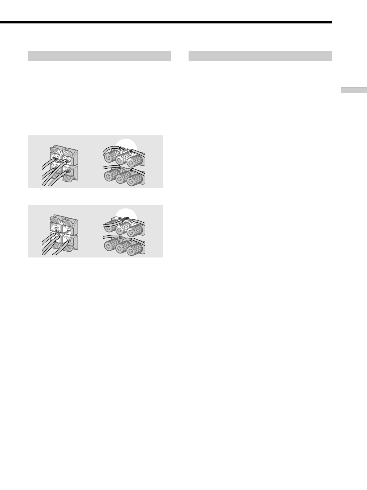
To avoid short-circuiting the speakers
Short-circuiting of the speakers may damage the receiver.
To prevent this, make sure to take the following
precautions when connecting the speakers.
Make sure the stripped ends of each speaker cord
do not touch another speaker terminal or the
stripped end of another speaker cord.
Speaker impedance
To enjoy multi channel surround, connect front, center,
and rear speakers with a nominal impedance of 8 ohms or
higher, and set the speaker IMPEDANCE SELECTOR to
“8Ω.” Check the instruction manual supplied with your
speakers if you’re not sure of their impedance. (This
information is usually printed on a label on the back of
the speaker.)
Hooking Up and Setting Up the Speaker System
Examples of poor conditions of the speaker cord
Stripped speaker cord is touching another speaker terminal.
Stripped cords are touching each other due to excessive
removal of insulation.
After connecting all the components, speakers,
and AC power cord, output a test tone to check
that all the speakers are connected correctly. For
details on outputting a test tone, see page 22.
You may connect a pair of speakers with a nominal
impedance between 4 and 8 ohms to all of the speaker
terminals. However, even if one speaker within this range
is connected, set the IMPEDANCE SELECTOR to “4Ω”.
Note
Be sure to connect front speakers with a nominal impedance of
8 ohms or higher if you want to select both sets (A+B) of front
speakers (see page 30). In this case, set the IMPEDANCE
SELECTOR to “4Ω”.
If no sound is heard from a speaker while outputting a
test tone or a test tone is output from a speaker other than
the one whose name is currently displayed on the
receiver, the speaker may be short-circuited. If this
happens, check the speaker connection again.
17
GB
Performing Initial Setup Operations
Once you have hooked up the speakers and turned on the
power, clear the receiver’s memory. Then specify the
speaker parameters (size, position, etc.) and perform any
other initial setup operations necessary for your system.
Hooking Up and Setting Up the Speaker System
Before turning on the receiver
Make sure that you have:
• Turned MASTER VOLUME to the leftmost position (0).
• Selected the appropriate front speakers (see “wj
SPEAKERS selector” on page 30).
Clearing the receiver’s memory
Before using your receiver for the first time, or when you
want to clear the receiver’s memory, do the following.
This procedure is not necessary if the demonstration
activates when you turn the power on.
1/u
?/1
•
•
•
•
–+ –+
–
+
–
+
1 Turn off the receiver.
2 Hold down ?/1 for 5 seconds.
The currently selected function, followed by the
demonstration message appears in the display. All of
the following items are reset or cleared:
• All preset stations are reset or cleared.
• All sound field parameters are reset to their factory
settings.
• All index names (of preset stations and program
sources) are cleared.
• All adjustments made with the SET UP button are
reset to their factory settings.
• The sound field memorized for each program source
and preset stations are cleared.
•
•
•
46
•
•
•
3
•
•
•
2
•
•
•
1
•
•
•
0
Performing initial setup operations
Before using your receiver for the first time, use the SET
UP button to adjust the setup parameters so that they
correspond to your system. You can adjust the following
items. For details on how to make adjustments, see the
page in parenthesis.
• Speaker size and placement (pages 19~22).
• Speaker distance (page 19).
• Whether other components will turn on or off
automatically via the CONTROL A1
(page 53).
• Whether the display turns off or not when you press
DIMMER (page 54).
• STR-DB940 only:
– 2 way remote control system operation (page 53).
– Selecting the color of the on-screen display (page 54).
– Select the TV color system of the monitor (except for
models of area U, CA) (page 54).
Demonstration Mode
5
•
•
•
•
•
•
7
•
•
•
8
•
•
•
9
•
•
•
10
The demonstration will activate the first time you turn on
the power. When the demonstration starts, the following
message appears in the display twice:
“Now Demonstration Mode!! To finish the
demonstration, please push POWER KEY while this
message appears in the display. Thank you!”
To cancel the demonstration
Press ?/1 to turn the receiver off during the previous
message. The next time you turn the receiver on, the
demonstration will not appear.
To view the demonstration
Hold down SET UP and press ?/1 to turn on the power.
Note
Running the demonstration will clear the receiver’s
memory. For details on what will be cleared, see “Clearing
the receiver’s memory” on this page.
control system
18
GB
Multi Channel Surround Setup
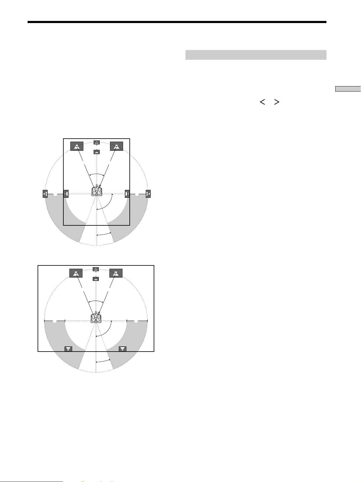
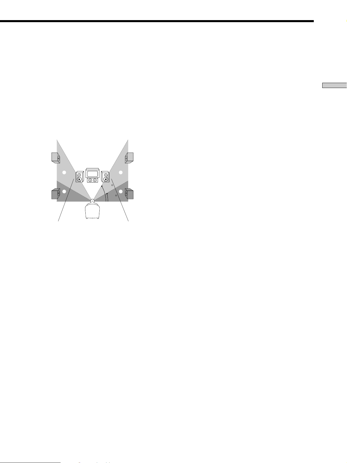
For the best possible surround sound all speakers should
be the same distance from the listening position (A).
However, this unit lets you to place the center speaker up
to 5 feet (1.5 meters) closer (B) and the rear speakers up
to 15 feet (4.5 meters) closer (C) to the listening position.
The front speakers can be placed from 3 to 40 feet (1.0 to
12.0 meters) from the listening position (A).
You can place the rear speakers either behind you or to
the side, depending on the shape of your room (etc.).
When placing rear speakers to your side
B
A A
45°
CC
90°
20°
When placing rear speakers behind you
Specifying the speaker parameters
1 Press ?/1 to turn on the receiver.
2 Press SET UP.
Hooking Up and Setting Up the Speaker System
3 Press the cursor buttons ( or ) to select the
parameter you want to adjust.
4 Turn the jog dial to select the setting you desire.
The setting is entered automatically.
5 Repeat steps 3 and 4 until you have set all of the
parameters that follow.
x Front speaker size (FRONT)
Initial setting : LARGE
• If you connect large speakers that will effectively
reproduce bass frequencies, select “LARGE”. Normally,
select “LARGE”.
• If the sound is distorted, or you feel a lack of surround
effects when using multi channel surround sound,
select “SMALL” to activate the bass redirection circuitry
and output the front channel bass frequencies from the
sub woofer.
• When the front speaker is set to “SMALL”, the center
and rear speakers are also automatically set to
“SMALL” (unless previously set to “NO”).
B
A A
45°
CC
90°
20°
Note
Do not place the center speaker farther away from the listening
position than the front speakers.
19
GB
Multi Channel Surround Setup
x Center speaker size (CENTER)
Initial setting : LARGE
• If you connect a large speaker that will effectively
reproduce bass frequencies, select “LARGE”. Normally,
select “LARGE”. However, if the front speakers are set
Hooking Up and Setting Up the Speaker System
to “SMALL”, you cannot set the center speaker to
“LARGE”.
• If the sound is distorted, or you feel a lack of surround
effects when using multi channel surround sound,
select “SMALL” to activate the bass redirection circuitry
and output the center channel bass frequencies from the
front speakers (if set to “LARGE”) or sub woofer. *
• If you do not connect a center speaker, select “NO”. The
sound of the center channel will be output from the
front speakers.*
2
x Rear speaker size (REAR)
Initial setting : LARGE
• If you connect large speakers that will effectively
reproduce bass frequencies, select “LARGE”. Normally,
select “LARGE”. However, if the front speakers are set
to “SMALL”, you cannot set the rear speakers to
“LARGE”.
• If the sound is distorted, or you feel a lack of surround
effects when using multi channel surround sound,
select “SMALL” to activate the bass redirection circuitry
and output the rear channel bass frequencies from the
sub woofer or other “LARGE” speakers.
• If you do not connect rear speakers, select “NO”.*
z
*1~*3 correspond to the following Dolby Pro Logic modes
*1 NORMAL
*2 PHANTOM
*3 3 STEREO
z
About speaker sizes (LARGE and SMALL)
Internally, the LARGE and SMALL settings for each speaker
determine whether or not the internal sound processor will cut
the bass signal from that channel. When the bass is cut from a
channel, the bass redirection circuitry sends the corresponding
bass frequencies to the sub woofer or other “LARGE” speakers.
However, since bass sounds have a certain amount of
directionality, it best not to cut them, if possible. Therefore, even
when using small speakers, you can set them to “LARGE” if you
want to output the bass frequencies from that speaker. On the
other hand, if you are using a large speaker, but prefer not to
1
have bass frequencies output from that speaker, set it to
“SMALL”.
If the overall sound level is lower than you prefer, set all speakers
to “LARGE”. If there is not enough bass, you can use the
equalizer to boost the bass levels. To adjust the equalizer, see
page 40.
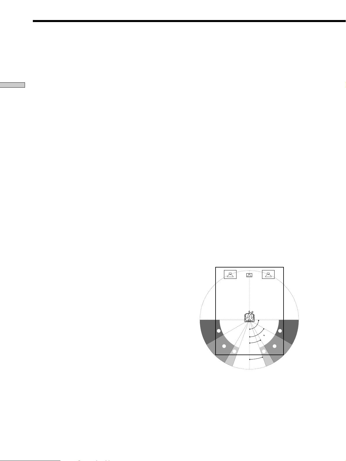
x Rear speaker position (REAR PLACE)*
Initial setting : BEHIND
This parameter lets you specify the location of your rear
speakers for proper implementation of the Digital Cinema
Sound surround modes in the “VIRTUAL” sound fields.
Refer to the illustration below.
• Select “SIDE” if the location of your rear speakers
corresponds to section A.
• Select “MIDDLE” if the location of your rear speakers
corresponds to section B.
• Select “BEHIND” if the location of your rear speakers
3
corresponds to section C.
This setting only effects the surround modes in the
“VIRTUAL” sound fields.
20
GB
A
B
90°
60°
30°
C C
20°
A
B
x Rear speaker height (REAR HEIGHT)*
Initial setting : LOW
This parameter lets you specify the height of your rear
speakers for proper implementation of the Digital Cinema
Sound surround modes in the “VIRTUAL” sound fields.
Refer to the illustration below.
• Select “LOW” if the location of your rear speakers
corresponds to section A.
• Select “HIGH” if the location of your rear speakers
corresponds to section B.
This setting only effects the surround modes in the
“VIRTUAL” sound fields.
B
A
B
60
A
30
* These parameters are not available when “Rear speaker
size (REAR)” is set to “NO”.
z
About the rear speaker position (SIDE, MIDDLE, and BEHIND)
This setting is designed specifically for implementation of the
Digital Cinema Sound modes in the “VIRTUAL” sound fields.
With the Digital Cinema Sound modes, speaker position is not as
critical as other modes. All of the modes in the “VIRTUAL”
sound fields were designed under the premise that the rear
speaker would be located behind the listening position, but
presentation remains fairly consistent even with the rear speakers
positioned at a rather wide angle. However, if the speakers are
pointing toward the listener from the immediate left and right of
the listening position, the “VIRTUAL” sound fields will not be
effective unless the rear speaker position parameter is set to
“SIDE”.
Nevertheless, each listening environment has many variables,
like wall reflections, and you may obtain better results using
“BEHIND” or “MIDDLE” if your speakers are located high above
the listening position, even if they are to the immediate left and
right.
Therefore, although it may result in a setting contrary to the
“Rear speaker position” explanation, we recommend that you
playback multi channel surround encoded software and listen to
the effect each setting has on your listening environment. Choose
the setting that provides a good sense of spaciousness and that
best succeeds in forming a cohesive space between the surround
sound from the rear speakers and the sound of the front speakers.
If you are not sure which sounds best, select “BEHIND” and then
use the speaker distance parameter and speaker level
adjustments to obtain proper balance.
x Sub woofer selection (SUB WOOFER)
Initial setting : YES
• If you connect a sub woofer, select “YES”.
• If you do not connect a sub woofer, select “NO”. This
activates the bass redirection circuitry and outputs the
LFE signals from other speakers.
• In order to take full advantage of the Dolby Digital
(AC-3) bass redirection circuitry, we recommend setting
the sub woofer’s cut off frequency as high as possible.
x Front speaker distance (FRONT)
Initial setting : 16 feet* (5.0 meter)
Set the distance from your listening position to the front
(left or right) speaker (A on page 19).
• Front speaker distance can be set in 1 foot* (0.1 meter)
steps from 3 to 40 feet* (1.0 to 12.0 meters).
• If both speakers are not placed an equal distance from
your listening position, set the distance to the closest
speaker.
* Models of area code U, CA only.
x Center speaker distance (CENTER)
Initial setting : 16 feet* (5.0 meter)
Set the distance from your listening position to the center
speaker.
• Center speaker distance can be set in 1 foot* (0.1 meter)
steps from a distance equal to the front speaker distance
(A on page 19) to a distance 5 feet* (1.5 meters) closer to
your listening position (B on page 19).
• Do not place the center speaker farther away from your
listening position than the front speakers.
* Models of area code U, CA only.
x Rear speaker distance (REAR)
Initial setting : 11 feet* (3.5 meter)
Set the distance from your listening position to the rear
(left or right) speaker.
• Rear speaker distance can be set in 1 foot* (0.1 meter)
steps from a distance equal to the front speaker distance
(A on page 19) to a distance 15 feet* (4.5 meters) closer
to your listening position (C on page 19).
• Do not place the rear speakers farther away from your
listening position than the front speakers.
• If both speakers are not placed an equal distance from
your listening position, set the distance to the closest
speaker.
* Models of area code U, CA only.
Hooking Up and Setting Up the Speaker System
21
GB

Multi Channel Surround Setup
z
About speaker distances
This unit allows you to input the speaker position in terms of
distance. However, it is not possible to set the center speaker
further than the front speakers. Also, the center speaker cannot be
set more that 5 feet* (1.5 meters) closer than the front speakers.
Likewise, the rear speakers can not be set farther away from the
Hooking Up and Setting Up the Speaker System
listening position than the front speakers. And they can be no
more than 15 feet* (4.5 meters) closer.
This is because incorrect speaker placement is not conducive to
the enjoyment of surround sound.
Please note that, setting the speaker distance closer than the
actual location of the speakers will cause a delay in the output of
the sound from that speaker. In other words, the speaker will
sound like it is farther away.
For example, setting the center speaker distance 3~6 feet* (1~2 m)
closer than the actual speaker position will create a fairly realistic
sensation of being “inside” the screen. If you cannot obtain a
satisfactory surround effect because the rear speakers are too
close, setting the rear speaker distance closer (shorter) than the
actual distance will create a larger soundstage.
Adjusting these parameter while listening to the sound often
results in much better surround sound. Give it a try!
* Models of area code U, CA only.
x Distance unit (DIST. UNIT)
Initial setting : feet* (meter)
Lets you select either feet or meters as the unit of measure
for setting distances. 1 foot corresponds to a 1 ms
difference.
* Models of area code U, CA only.
x Front speaker crossover frequency
(FRONT SP >)
Initial setting : 120 Hz
Lets you adjust the front speaker bass crossover frequency
when the front speakers are set to “SMALL”. The
frequency can be adjusted in 30 Hz steps from 60 Hz to
180 Hz.
x Center speaker crossover frequency
(CENTER SP >)
Initial setting : 120 Hz
Lets you to adjust the center speaker bass crossover
frequency when the center speaker is set to “SMALL”.
The frequency can be adjusted in 30 Hz steps from 60 Hz
to 180 Hz.
Adjusting the speaker volume
Use the remote while seated in your listening position to
adjust the volume of each speaker.
Note
This unit incorporates a new test tone with a frequency centered
at 800 Hz for easier speaker volume adjustment.
1 Press ?/1 to turn on the receiver.
2 Press TEST TONE on the front panel (except for
models of area code CED) or on the supplied
remote.
You will hear the test tone from each speaker in
sequence.
3 Adjust the volume level so that the volume of the
test tone from each speaker sounds the same
when you are in your main listening position.
• To adjust the balance of the front right and front left
speakers, use the front balance parameter in the
LEVEL menu (see page 39).
• To adjust the balance of the rear right and rear left
speakers, use the rear balance parameter in the
LEVEL menu (see page 39).
• To adjust the volume level of the center speaker,
press the LEVEL CENTER +/– buttons on the
remote.
• To adjust the volume level of the rear speakers, press
the LEVEL REAR +/– buttons on the remote.
4 Press TEST TONE again to turn off the test tone.
Note
The test tone cannot be output when the receiver is set to 5.1CH
INPUT.
z
You can adjust the volume level of all speakers at the same
time
Rotate MASTER VOLUME on the main unit or press MASTER
VOLUME +/– on the remote.
x Rear speaker crossover frequency (REAR SP >)
Initial setting : 120 Hz
Lets you adjust the rear speaker bass crossover frequency
when the rear speakers are set to “SMALL”. The
frequency can be adjusted in 30 Hz steps from 60 Hz to
180 Hz.
GB
22
Notes
• The front balance, rear balance, center level, and rear level are
shown in the display during adjustment.
• Although these adjustments can also be made via the front
panel using the LEVEL menu (when the test tone is output, the
receiver switches to the LEVEL menu automatically), we
recommend you follow the procedure described above and
adjust the speaker levels from your listening position using the
remote control.
Before You Use Your
Receiver
Before turning on the receiver
Make sure that you have:
• Turned MASTER VOLUME to the leftmost position (0).
• Selected the appropriate front speakers (see “wj
SPEAKERS selector” on page 30).
Hooking Up and Setting Up the Speaker System
Checking the connections
After connecting all of your components to the receiver,
do the following to verify that the connections were made
correctly.
1/u
?/1
•
•
•
•
–+ –+
–
+
MASTER VOLUME
5
•
•
•
46
•
•
•
3
•
•
•
2
•
•
•
1
•
•
•
0
+
–
•
•
•
•
•
•
7
•
•
•
8
•
•
•
9
•
•
•
10
FUNCTION
1 Press ?/1 to turn on the receiver.
2 Rotate FUNCTION to select a component (program
source) that you connected (e.g., CD player or tape
deck).
3 Turn on the component and start playing it.
4 Rotate MASTER VOLUME to turn up the volume.
If you do not obtain normal sound output after
performing this procedure, look for the reason in the
checklist on the following page and take the appropriate
measures to correct the problem.
23
GB

Before You Use Your Receiver
There is no sound no matter which component is
selected.
, Check that both the receiver and all components
are turned on.
, Check that the MASTER VOLUME control is not
Hooking Up and Setting Up the Speaker System
set at 0.
, Check that the SPEAKERS selector is not set to
OFF or to a position for front speakers that are not
connected to the receiver (see “wj SPEAKERS
selector” on page 30).
, Check that all speaker cords are connected
correctly.
, Press the MUTING button to turn off the indicator
on the button.
There’s no sound from a specific component.
, Check that the component is connected correctly to
the audio input jacks for that component.
, Check that the cord(s) used for the connection is
(are) fully inserted into the jacks on both the
receiver and the component.
No sound is heard from one of the front
speakers.
, Connect a pair of headphones to the PHONES jack
and set the SPEAKERS selector to OFF to verify
that sound is output from the headphones (see “wj
SPEAKERS selector” and “PHONES jack” on page
30).
If only one channel is output from the headphones,
the component may not be connected to the
receiver correctly. Check that all the cords are fully
inserted into the jacks on both the receiver and the
component.
If both channels are output from the headphones,
the front speaker may not be connected to the
receiver correctly. Check the connection of the
front speaker which is not outputting any sound.
If you encounter a problem that is not included above, see
“Troubleshooting” on page 56.
24
GB

Hooking Up and Setting Up the Speaker System
25
GB

Location of
Parts and Basic
Operations
This chapter provides information
about the locations and functions of
the buttons and controls on the front
panel. It also explains basic
operations.
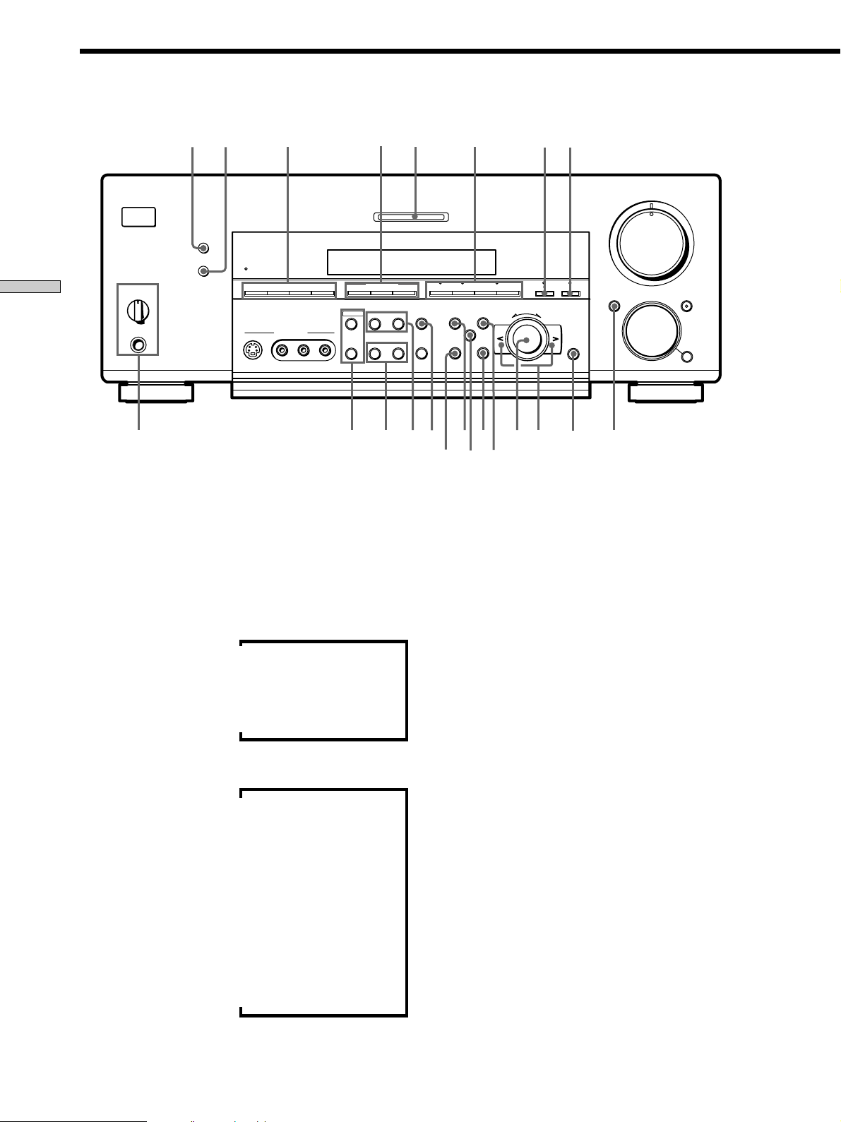
Front Panel Parts
Description
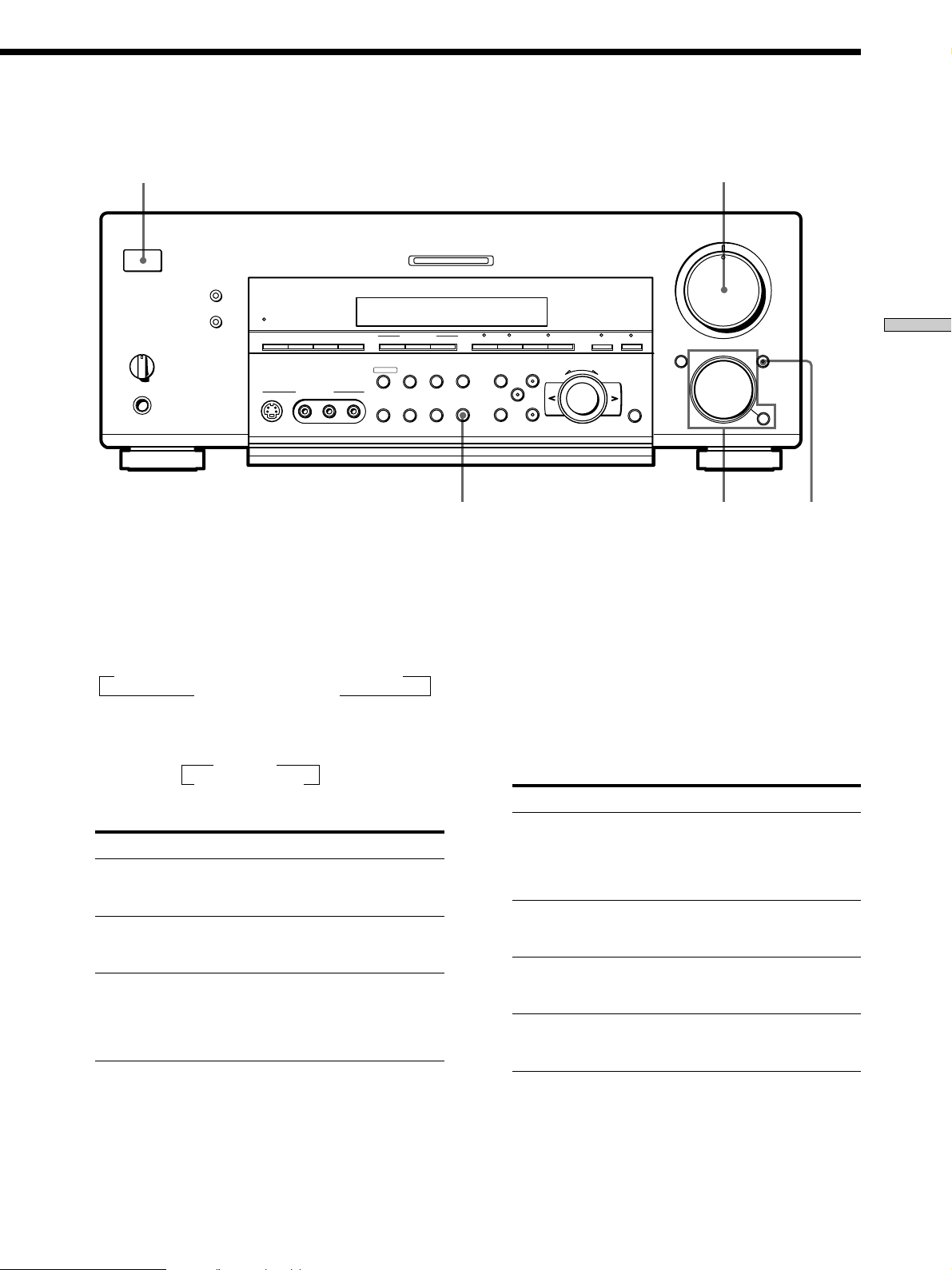
1 ?/1 switch
Press to turn the receiver on and off.
• Before you turn on the receiver, make sure that you have
turned the MASTER VOLUME control to the leftmost
position to avoid damaging your speakers.
2 MASTER VOLUME control
After turning on the component you selected, rotate to
adjust the volume.
3 MUTING button
Press to mute the sound. The indicator on the button
lights up when the sound is muted.
4 FUNCTION control
Rotate to select the component you want to use.
To select Rotate to light
VCR VIDEO 1 or VIDEO 2
Camcorder or video game VIDEO 3
DVD or LD player DVD/LD
TV or satellite tuner TV/SAT
Tape deck TAPE (STR-DB940)
MD or Tape deck MD/TAPE (STR-DB840)
MD or DAT deck MD/DAT (STR-DB940 only)
CD player CD
Built in tuner TUNER
Turntable PHONO
After selecting the component, turn on the component
you selected and play the program source.
26
• After selecting VCR, camcorder, video game, DVD player,
or LD player, turn on the TV and set the TV’s video input
to match the component you selected.
GB
SPEAKERS
OFF
+B
A
1
?/1
•
•
PHONES
2
MASTER VOLUME
5
•
•
•
•
•
•
46
MULTI CHANNEL DECODING
DIMMER
DISPLAY
A
B
•
•
BASS BOOST
VIDEO 3 INPUT
MEMORY
FM MODE
CINEMA STUDIO EX.
–
MODE–+SHIFT A B A.F.D.
SET UP
NAME
LEVEL
SUR
EQ
+
–
ENTER
+
EQUALIZER
INPUT
MODE
PRESET
– + C 2 CH ANLG DIRECT 5.1CH INPUTFM/AM
TUNING
RLVIDEOS-VIDEO AUDIO
•
•
•
3
•
•
•
2
•
•
•
1
•
•
•
0
DOOR OPEN FUNCTION MUTING
•
•
•
•
10
MODE
•
7
•
•
•
8
•
•
•
9
•
Location of Parts and Basic Amplifier Operations
345
MODE button
Press to select and play another video/audio source in
combination with the selected component.
Each time you press the button, the display changes as
follows:
Standard display (When 5.1CH INPUT is not selected)
t V:XXX t A:XXX t 2ND AUDIO [XXX]*
selected component T
When 5.1CH INPUT is selected
t V:XXX
5.1CH INPUT T
* STR-DB940 only.
Press MODE to display And rotate FUNCTION to select
V:XXX Any video source to enjoy with
the audio from the selected
component
A:XXX Any audio source to enjoy with
the video from the selected
component
2ND AUDIO [XXX] An audio source (except
(STR-DB940 only) PHONO) to enjoy in your sub
room. “SOURCE” selects the
same program source as the main
FUNCTION control**
** Even if 2ND AUDIO [SOURCE] is selected, no sound is output
when the receiver is set to 5.1CH INPUT. Only signals from
components connected to the analog inputs are output through
the 2ND AUDIO jacks. No signals are ouput from components
connected to only the digital inputs.
z Function indicators
Normally, the indicator above the selected function lights orange.
However, when MODE is used to select a different video (V:XXX)
or audio (A:XXX) source, the video function lights green and the
audio function lights orange. This also occurs when you select
audio components (like CD).
5 INPUT MODE button
Press to select the input mode for your digital
components (DVD/LD, TV/SAT, and MD/DAT
(STR-DB940) or MD/TAPE (STR-DB840)).
Each press switches the input mode of the currently
selected component.
Select To
AUTO Give priority to digital signals
when there are both digital and
analog connections. If there are
no digital signals, analog is
selected
DIGITAL (OPTICAL) Specify the digital audio signals
input to the DIGITAL OPTICAL
input jacks
DIGITAL (COAXIAL) Specify the digital audio signals
input to the DIGITAL COAXIAL
input jacks (DVD/LD only)
ANALOG Specify the analog audio signals
input to the AUDIO IN (L and R)
jacks
27
GB
Front Panel Parts Description
7
6
?/1
DIMMER
DISPLAY
SPEAKERS
A
B
OFF
Location of Parts and Basic Amplifier Operations
•
•
•
+
B
A
•
PHONES
BASS BOOST
8
VIDEO 3 INPUT
PRESET
– + C 2 CH ANLG DIRECT 5.1CH INPUTFM/AM
TUNING
RLVIDEOS-VIDEO AUDIO
6 DIMMER button
Press repeatedly to adjust the brightness of the display.
When you want to turn off the display, set in the
“DIMM. RANGE” parameter in the SET UP menu
(page 54).
MEMORY
FM MODE
whwj
9
MULTI CHANNEL DECODING
CINEMA STUDIO EX.
–
+
wg
q; qa
SET UP
EQUALIZER
INPUT
MODE
wdwf
SUR
NAME
ql
wa
ws
w;
* Index name appears only when you have assigned one to the
** These indications appear only during RDS reception. (Models of
qs
qd
MASTER VOLUME
5
•
•
•
•
•
•
LEVEL
46
•
•
•
3
•
•
•
2
•
•
•
1
•
•
•
MODE–+SHIFT A B A.F.D.
+
–
EQ
qj
ENTER
qh
0
DOOR OPEN FUNCTION MUTING
qfqg
•
•
•
10
MODE
•
7
•
•
•
8
•
•
•
9
•
•
qk
component or preset station (see page 51). Index name does not
appear when only blank spaces have been entered, or it is the
same as the function button.
area code CED only. See page 47).
7 DISPLAY button
Press repeatedly to change the information on the
display window as follows:
Index name of the component
Sound field applied to the program source
v
v
Selected component
v
When the tuner is selected
Index name of the preset station*
v
or program station name**
v
Frequency
v
Program type indication**
v
Radio text**
v
Current time**
v
Sound field applied to the band
or the preset station
8 The following buttons operate the built-in tuner. For
details, see “Receiving Broadcasts” starting from page
43.
FM/AM button
Selects the FM or AM band.
SHIFT button
Selects a memory page for preset stations.
PRESET TUNING +/– buttons
Scans all preset stations.
9 CINEMA STUDIO EX. A~C buttons
Press to select CINEMA STUDIO EX. A~C sound field.
For details, see “CINEMA STUDIO EX. A~C” on page
33.
0 MULTI CHANNEL DECODING indicator
This indicator lights when the unit is decoding signals
recorded in a multi channel format.
28
GB
qa Use these buttons to enjoy surround sound. For
details, see “Enjoying Surround Sound” starting from
page 31.
A.F.D. button / indicator
Press to set the receiver to automatically detect the
type of audio signal being input and perform proper
decoding (if necessary). For details, see “AUTO
FORMAT DECODING” on page 35.
2CH button / indicator
Press to output sound from only the front (left and
right) speakers. For details, see “2 CHANNEL” on
pate 35.
MODE +/– buttons / indicator
Press repeatedly to select the sound field you desire.
For details, see “Selecting a Sound Field” on page 32.
• Sound fields are not compatible with 96 kHz digital audio
signals.
qs ANLG DIRECT button
Press to listen to an analog source without digital
processing by the equalizer, sound field, etc.
For details, see “ANALOG DIRECT” on page 35.
qd 5.1CH INPUT button
Press to enjoy the audio source connected to the 5.1CH
INPUT jacks. Press 5.1 CH again to return to the
original function.
• When 5.1CH INPUT is selected, the equalizer, bass boost,
and sound field effects do not function.
qf DOOR OPEN button
Press to open the door on the front panel.
qg ENTER button
Press to enter individual characters for the preset
station and program source names.
qh Cursor buttons (
/ )
Press to select various speaker level, surround, and
equalizer parameters (etc.).
qj Jog dial
Turn to adjust the selected speaker level, surround,
and equalizer parameters (etc.).
qk LEVEL button
Press to activate the speaker level parameters (page
39). The indicator on the button lights up and you can
adjust the various speaker level parameters (front
balance, rear balance, etc.).
ql EQ button
Press to activate the equalizer parameters (page 40).
The indicator on the button lights up and you can
adjust the various equalizer parameters.
Location of Parts and Basic Amplifier Operations
w; SUR button
Press to activate the surround parameters (page 38).
The indicator on the button lights up and you can
adjust the various surround parameters (effect level,
wall type, etc.).
wa SET UP button
Press to activate the setup mode, then use the cursor
buttons (qh) to select any of the following parameters.
You can make various settings using the jog dial (qj).
When you select You can
Speaker setup Specify the front, center, rear speaker
sizes, the rear speaker position, and
whether or not you are using a sub
woofer (page 19).
Speaker Distance Specify the front, center, and rear speaker
distances and the unit of measurement
(page 21).
Crossover Specify the front, center, and rear speaker
frequency* bass crossover frequency (page 22).
Auto Function Specify whether or not Sony components
connected via Control A1 cords will turn
on or off when selected using the
function buttons (page 53).
2 way remote Turn on or off response to remote
(STR-DB940 only) signals sent from the 2 way remote (page
53).
Color system Select the TV color system of the monitor.
(STR-DB940 of area
codes other than
U, CA)
OSD color Specify the color of the on-screen
(STR-DB940 only) display (page 54).
Dimmer Range Specify the display to turn off when you
press the DIMMER button several times
(page 54).
* Only when the speaker is set to“SMALL” in the speaker setup
parameter.
29
GB
Front Panel Parts Description
ws NAME button
Press to activate the name function and enter names
for preset stations and program sources (page 51).
wd EQUALIZER button
Press to turn the equalizer on or off. The EQ indicator
in the display lights in the display when the equalizer
is turned on.
When you adjust the equalizer using the EQ
parameters (page 40), the settings are stored
Location of Parts and Basic Amplifier Operations
automatically and can be reproduced whenever you
turn on the equalizer.
• The equalizer is not compatible with 96 kHz digital audio
signals and during 5.1CH input.
wf The following buttons operate the built-in tuner. For
details, see “Receiving Broadcasts” starting from page
43.
Models of area code CED
TUNING/PTY SELECT +/– buttons
Scans all the available radio stations.
Selects program types during PTY operations.
Models of other area codes
TUNING +/– buttons
Scans all the available radio stations.
wh The following buttons operate the built-in tuner. For
details, see “Receiving Broadcasts” starting from page
43.
MEMORY button
Press to memorize a preset station.
FM MODE button
If “STEREO” flashes in the display and the FM stereo
reception is poor, press this button. You will not have
the stereo effect but the sound is improved.
wj SPEAKERS selector
Set according to the front speakers you want to drive.
Set to To select
A The speakers connected to the FRONT
B The speakers connected to the FRONT
A+B* The speakers connected to both the FRONT
OFF No speaker output
Be sure to connect front speakers with a nominal impedance of
*
8 ohms or higher if you want to select both sets (A+B) of front
speakers. In this case, set the IMPEDANCE SELECTOR to
“4Ω”
SPEAKERS A terminals
SPEAKERS B terminals
SPEAKERS A and B terminals (parallel
connection)
wg
Models of area code CED
The following buttons operate the built-in tuner.
For details, see “Using the Radio Data System
(RDS)” starting from page 47.
RDS EON button
Press to set the receiver to automatically switch to
stations broadcasting traffic announcements, news,
or information program. The EON button does not
function during AM reception.
RDS PTY button
Press to scan stations by program type. The PTY
button does not function during AM reception.
Models of other area codes
TEST TONE button
Press to output the test tone.
SLEEP button
Press to activate the sleep timer.
PHONES jack
Connects headphones.
• To use the headphones, set the SPEAKERS selector to OFF
to output sound to the headphones.
• To enjoy surround sound from the headphones, we
recommend selecting the HEADPHONE THEATER sound
field. Selecting other sound fields when the SPEAKERS
selector is set to OFF automatically presents a 2 channel
(stereo) downmix from the headphones.
30
GB
Loading…
Просмотр
Доступно к просмотру 192 страницы. Рекомендуем вам скачать файл инструкции, поскольку онлайн просмотр документа может сильно отличаться от оригинала.
-
4-229-127-82(1)
FM Stereo
FM-AM Receiver
Operating Instructions                                                   GB
Instrukcja obslugi                                                       PL
Инструкция по эксплуатации                                               RU
STR-DB940
STR-DB840
a 2000 Sony Corporation
-
WARNING                           Precautions
To prevent fire or shock          On safety
hazard, do not expose the         Should any solid object or liquid fall into
the cabinet, unplug the receiver and have it
unit to rain or moisture.
checked by qualified personnel before
operating it any further.
To avoid electrical shock, do not
On power sources
open the cabinet. Refer
• Before operating the receiver, check that
servicing to qualified personnel    the operating voltage is identical with
only.                               your local power supply. The operating
voltage is indicated on the nameplate at
the rear of the receiver.
Do not install the appliance in a
• The unit is not disconnected from the AC
confined space, such as a           power source (mains) as long as it is
bookcase or built-in cabinet.       connected to the wall outlet, even if the
unit itself has been turned off.
• If you are not going to use the receiver
for a long time, be sure to disconnect the
receiver from the wall outlet. To
disconnect the AC power cord, grasp the
plug itself; never pull the cord.
• AC power cord must be changed only at
the qualified service shop.
On placement
• Place the receiver in a location with
adequate ventilation to prevent heat
buildup and prolong the life of the
receiver.
• Do not place the receiver near heat
sources, or in a place subject to direct
sunlight, excessive dust or mechanical
shock.
• Do not place anything on top of the
cabinet that might block the ventilation
holes and cause malfunctions.
On operation
Before connecting other components, be
sure to turn off and unplug the receiver.
On cleaning
Clean the cabinet, panel and controls with
a soft cloth slightly moistened with a mild
detergent solution. Do not use any type of
abrasive pad, scouring powder or solvent
such as alcohol or benzine.
If you have any question or problem
concerning your receiver, please
consult your nearest Sony dealer.
2 GB
-
About This Manual                                   TABLE OF CONTENTS
The instructions in this manual are for models
STR-DB940 and STR-DB840. Check your model number    Hooking Up the Components 4
by looking at the lower right corner of the front panel.  In  Unpacking  4
this manual, the STR-DB940 is used for illustration  Antenna Hookups 5
purposes unless stated otherwise. Any difference in  Audio Component Hookups 6
operation is clearly indicated in the text, for example,  Video Component Hookups  8
“STR-DB940 only.”
Digital Component Hookups 9
Type of differences                                 5.1CH Input Hookups   11
Model        DB940     DB840                  Other Hookups 12
Feature
5 audio inputs       z                              Hooking Up and Setting Up the
4 audio inputs                 z                    Speaker System         15
Speaker System Hookup 16
Performing Initial Setup Operations 18
About area codes                                  Multi Channel Surround Setup 19
The area code of the player you purchased is shown on the  Before You Use Your Receiver  23
lower portion of the rear panel (see the illustration below).
Location of Parts and Basic
B  FRONT  A  REAR  CENTER  FRONT  REAR  SUB WOOFER CENTER
L
R                                                                                     GB
L  R  L  R  L
PRE OUT
SELECTOR
4 W  8 W IMPEDANCE                Operations 26
SPEAKERS   IMPEDANCE  USE 4 – 16W
AC  OUTLET
Front Panel Parts Description 26
4-XXX-XXX-XX AA
Area code       Enjoying Surround Sound            31
Any differences in operation, according to the area code, are  Selecting a Sound Field 32
clearly indicated in the text, for example, “Models of area  Understanding the Multi-Channel Surround
code AA only”.                                      Displays 36
Customizing Sound Fields 38
Conventions
• The instructions in this manual describe the controls on  Receiving Broadcasts 43
the receiver. You can also use the controls on the  Storing FM Stations Automatically
supplied remote if they have the same or similar names  (AUTOBETICAL)*** 44
as those on the receiver. For details on the use of your  Direct Tuning 45
remote, refer to the separate operating instructions  Automatic Tuning 45
supplied with the remote.                         Preset Tuning 46
• The following icon is used in this manual:        Using the Radio Data System (RDS)*** 47
z Indicates hints and tips for making the task easier.  ***Models of area code CED only.
This receiver incorporates Dolby* Digital and Pro Logic
Surround and the DTS** Digital Surround System.     Other Operations         50
Naming Preset Stations and Program Sources 51
*  Manufactured under license from Dolby Laboratories.  Recording  51
“Dolby”, “AC-3”, “Pro Logic” and the double-D symbol ; are  Using the Sleep Timer  52
trademarks of Dolby Laboratories.                 Adjustments Using the SET UP Button 53
Confidential unpublished Works. © 1992-1997 Dolby Laboratories.  CONTROL A1  Control System  54
All rights reserved.
** Manufactured under license from Digital Theater Systems, Inc. US
Pat. No. 5,451,942 and other worldwide patents issued and pending.  Additional Information 56
“DTS” and “DTS Digital Surround” are trademarks of Digital  Troubleshooting 56
Theater Systems, Inc. © 1996 Digital Theater Systems, Inc. All  Specifications 58
rights reserved.
Glossary 61
Tables of Settings Using SUR, LEVEL, EQ, and SET
UP buttons  62
Index  64
3 GB
- 1
- 2
- 3
- 4
- 192
- Инструкции и руководства
- Бренды
- Sony
- str-db840
- Справочник Пользователя
4-229-127-14(2)
FM Stereo
FM-AM Receiver
Operating Instructions
2000 Sony Corporation
STR-DB940
STR-DB840
Sony STR-DB840 Receiver PDF User Guides and Manuals for Free Download: Found (4) Manuals for Sony STR-DB840 Device Model (Service Manual, Operating Instructions Manual)
When exploring the realm of audio receivers, the Sony STR-DB840 stands out as a remarkable unit that perfectly blends performance, versatility, and user-friendly features. Introduced during the late 1990s, this audio receiver has retained a loyal following due to its impressive capabilities and robust build quality, making it a worthy contender for anyone looking to enhance their home theater system.
One of the defining characteristics of the STR-DB840 is its rich feature set. Boasting a power output of 100 watts per channel, this receiver is designed to deliver a hearty performance in most residential setups. The output is more than adequate for driving larger speakers and filling a room with immersive sound. Here are some notable features:
- Multi-channel audio support: The STR-DB840 supports Dolby Digital and DTS surround sound formats, enabling users to enjoy an exceptional home theater experience.
- Built-in tuner: With an FM/AM tuner, this receiver offers a wide range of radio options, ensuring that music lovers can enjoy their favorite stations without any additional equipment.
- Multiple inputs: The receiver provides a variety of input options, including multiple digital, optical, and coaxial inputs, allowing connection to various sources such as DVD players, gaming consoles, and set-top boxes.
- User-friendly interface: The intuitive setup and controls make it easy for both novice users and audiophiles to operate the unit, ensuring a seamless experience.
Another aspect that makes the Sony STR-DB840 noteworthy is its durability. Constructed with high-quality materials, the unit feels solid and well-built. Even after years of use, it is known for maintaining performance without significant degradation, often rivaling more recent models on the market. Additionally, the stylish design ensures it fits well within any home décor, making it a practical choice for audio enthusiasts who are also concerned about aesthetics.
In terms of sound quality, the STR-DB840 excels in delivering clear and dynamic audio. Whether watching movies or listening to music, users often remark on the clarity of dialogue and the depth of soundstage provided by this receiver. It manages to balance power and detail, ensuring that even the most nuanced audio tracks are presented with richness.
Moreover, setup and customization options available with the Sony STR-DB840 are quite commendable. Users can configure various sound modes and settings according to their preferences and the specifics of their room acoustics. This flexibility allows individuals to tailor the audio experience, enhancing their overall enjoyment.
However, it’s worth noting that the STR-DB840 lacks some of the advanced features found in modern receivers, such as wireless connectivity and support for high-resolution audio formats. Nevertheless, its price point reflects its capabilities and it serves as an excellent choice for those who prioritize traditional audio performance over the latest technology trends.
In conclusion, the Sony STR-DB840 offers a well-rounded audio experience that transcends time. Its commendable power, sound quality, and range of features make it a fantastic option for both casual listeners and home theater enthusiasts alike. Despite the technological advancements seen in newer models, the STR-DB840 remains a classic in the realm of audio receivers, proving that sometimes, simplicity and performance reign supreme.
Sony STR-DB840 Operating Instructions
Sony STR-DB840 Specification
The Sony STR-DB840 is a versatile AV receiver designed to enhance home audio and video experiences with robust performance and advanced features. It supports Dolby Digital, DTS, and Dolby Pro Logic decoding, offering a rich, immersive sound quality tailored for home theaters. The receiver delivers a power output of 100 watts per channel across five channels, providing ample audio power for a wide range of speaker setups. It includes multiple audio and video input options, such as composite, S-Video, and optical digital inputs, ensuring compatibility with various media sources and devices. The STR-DB840 features a user-friendly interface with an intuitive on-screen display, facilitating easy navigation and setup. Its design includes a high-fidelity FM/AM tuner with 30 station presets, allowing users to enjoy a wide selection of radio broadcasts. The receiver is equipped with a range of sound field programs to customize the audio experience based on content type, such as movies, music, or sports. Additionally, the unit boasts a durable construction with a sleek, modern aesthetic that integrates seamlessly into any entertainment system. The Sony STR-DB840 is engineered to provide reliable performance, making it a suitable choice for audiophiles seeking a high-quality, adaptable AV receiver for their home entertainment needs.
Sony STR-DB840 F.A.Q.
To perform a factory reset on your Sony STR-DB840, turn off the receiver. Press and hold the «Power» button while pressing the «Preset Tuning +», «Preset Tuning –», and «Tuning Mode» buttons simultaneously. Release all buttons when «All Clear» appears on the display.
First, check all cable connections to ensure they are secure. Make sure the correct input source is selected. Verify that the speakers are properly connected and that the speaker settings are configured correctly in the setup menu. Lastly, ensure the volume is turned up and not muted.
The Sony STR-DB840 does not have built-in Bluetooth capability. To connect a Bluetooth device, you will need an external Bluetooth adapter. Connect the adapter to the receiver’s audio input and pair your device with the adapter following its instructions.
Unplug the receiver before cleaning. Use a soft, dry cloth to wipe the exterior. Avoid using any liquids or chemical cleaners. For stubborn dirt, slightly dampen the cloth with water, but ensure no moisture enters the unit.
To set up surround sound, connect the speakers to the appropriate terminals on the receiver. Access the setup menu and configure the speaker settings, ensuring you select the correct size and distance for each speaker. Use the test tone feature to balance the speaker levels.
Check if the receiver is properly plugged in and turned on. If the display is still not working, try resetting the unit to factory settings. If the problem persists, it may require professional repair.
Ensure the FM antenna is properly connected. Try repositioning the antenna for better signal reception. You may also use an external antenna for stronger signals. Avoid placing the receiver near devices that may cause interference.
Yes, you can connect a subwoofer to the Sony STR-DB840 using the subwoofer pre-out connection. Connect the subwoofer cable to the pre-out jack on the receiver and the input on the subwoofer. Adjust the subwoofer settings in the receiver’s setup menu.
The Sony STR-DB840 does not support firmware updates as it is an older model. Ensure all components and connections are functioning optimally for the best performance.
The Sony STR-DB840 supports various audio formats, including Dolby Digital, DTS, and PCM. It is advisable to consult the user manual for a detailed list of supported formats and specifications.