
-
Русский
- English
- Español
- Italiano
- Русский
- ไทย
- Việt
- Türkçe
- 日本語
Общий векторный преобразователь частоты переменного тока
Преобразователь переменного тока серии Shihlin SS2 является одним из самых популярных и экономичных преобразователей переменного тока, разработанных и произведенных компанией Shihlin Electric. Благодаря оптимизированной встроенной ручке-шаттлу, преобразователь переменного тока серии SS2 обеспечивает клиентам более простой способ регулировки выходной частоты и установки параметров. Он также оснащен многофункциональными входными/выходными терминалами и конструкцией DIN-рейки для удобной установки.
Спецификация
- Выходная частота: 0.1 ~ 650 Гц
- Точность выходной частоты: 0.01%
- Регулируемая 5-точечная V/F кривая и векторное управление.
- Встроенный PID-контроль.
- Встроенные RS485, MODBUS и протокол Shihlin.
- Поддержка монтажа на DIN-рейку.
- 2 типа аналоговых настроек: 0 — 10V и 4 — 20mA
- Многофункциональные входные/выходные терминалы.
Диапазон мощности
Применения
- Конвейеры, упаковочные машины, шлифовальные машины, покрасочные машины, машины для окраски, текстильные машины.
- Скачать файлы
- Видео
-
SS2 в режиме управления положением
SS2 и фрезерный станок
AC привод SC3: как использовать клавиатуру для управления скоростью пошаговое руководство p79=1
SC3 AC привод как использовать внешний кнопочный переключатель и потенциометр для управления учебное пособие стр.79=2
Каталог VFD Shihlin
Скачайте каталог VFD Shihlin для получения дополнительной информации.
Серия SS2 | Производитель терморегуляторов CE | Shihlin
Основанная на Тайване с 1955 года, Shihlin Electric & Engineering Corporation — Automation является ведущим инноватором в области электротехники и автоматизации.Их основные продукты включают Серия SS2, температурные контроллеры, преобразователи переменного тока, мощные инверторы, преобразователи переменного тока, серводвигатели, удобные интерфейсы HMI, преобразователи переменного тока HVAC с открытым циклом и общие решения, обеспечивающие комплексные решения для инфраструктуры и энергетики.
Shihlin FA Group установила сотрудничество с производителями брендов, закрепив долгосрочные заказы ODM/OEM от японских и европейских компаний. Основные продукты включают инверторы, преобразователи переменного тока, интегрированные решения, сервомоторы, HMIs и многое другое. В течение длительного времени компания удерживает лидирующую позицию на внутреннем рынке с передовыми технологиями в области тяжелых электрических систем, электрооборудования, машин и автоматизации. Благодаря тщательному развертыванию и усердной работе, компания также достигла замечательного успеха на зарубежном рынке.
Shihlin Electric — Automation предлагает клиентам комплексные решения для промышленной автоматизации с 1955 года, обеспечивая передовые технологии и 60-летний опыт работы. Shihlin Electric — Automation гарантирует удовлетворение потребностей каждого клиента.
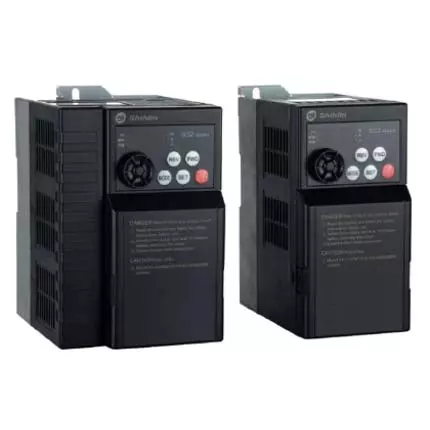
Shihlin Electric SS2 Series AC Drive
Installation Guide
Compact Design Vector control AC Drive
SS2—021-0.4K~2.2K
SS2—023—0.4K~3.7K
SS2—043—0.4K~5.5K
Thank you for choosing Shihlin SS2 series AC Drive.
The instruction will describe on the use and points for attention of products. Before installing, please be sure to carefully read the
Instruction, so that the inverter can be used in proper and safe way.
1) Safety Instructions
Installation, operation, maintenance and inspection must be performed by qualified personnel.
In this instruction, the safety instruction levels are classified into «Warning» and «Caution».
Warning: Incorrect handling may cause hazardous conditions, resulting in death or severe injury.
Caution: Incorrect handling may cause hazardous conditions, resulting in medium or slight injury, or may cause only material damage.
While the inverter power is ON, do not open the front cover or the wiring cover. Do not run the inverter with the front cover or the wiring cover
removed. Otherwise you may access the exposed high voltage terminals or the charging part of the circuitry and get an electric shock.
It is crucial to turn off the motor drive power before any wiring installation or inspection is made. Even if power supply was cut off, residual voltage is
in the internal capacitor. After the power cut off, waiting time should be no shorter than the time in inverter logo.
The inverter must be connected to the ground properly.
Do not operate or touch the radiator or handle the cables with wet hands. Otherwise you may get an electric shock.
Do not change the cooling fan while power is ON. It is dangerous to change the cooling fan while power is ON.
The voltage applied to each terminal must be the ones specified in the Instruction Manual. Otherwise burst, damage, etc. may occur.
Don’t conduct a pressure test on components inside inverter, for semiconductor of inverter is easily to be broke down and damaged by high voltage.
While power is ON or for some time after power-OFF, do not touch the inverter as it will be extremely hot. Touching these devices may cause a burn.
The cables must be connected to the correct terminals. Otherwise burst, damage, etc. may occur.
The polarity (+ and -) must be correct. Otherwise burst, damage, etc. may occur.
Inverter must be installed on a nonflammable wall without holes (so that nobody touches the inverter heat sink on the rear side, etc.). Mounting it to
or near flammable material may cause a fire.
If the inverter has become faulty, the inverter power must be switched OFF. A continuous flow of large current may cause a fire.
2) Description of Product Model Number
SS2 — 043 — 0.75K — * *
—043:440V three-phase
—023:220V three-phase
—021:220V single-phase
None:General model
—**:Customer motor or dedicated motor or region
difference
3) Installation Environment
-10 ~ +50℃ (non-freezing).
Below 90%Rh (non-condensing).
Indoor, no corrosive gas, no flammable gas, no flammable powder.
Altitude below 1000 meters
4) Installation and Wiring
Please ensure vertical arrangement to keep the cooling effect:
(a) Vertical arrangement (b)Horizontal arrangement (c) Level arrangement
Please comply with installation conditions shown below to ensure enough ventilation space and wiring space for inverter
cooling
Arrangement of single or paralleling inverter:
Unit :mm
Arrangement of multiple inverters:
Enclosure
Guide
Inverter
Inverter Inverter Inverter
Inverter Inverter
Guide
Guide
Enclosure
(a)Horizontal arrangement (b)Vertical arrangement
Note1: When mounting inverters of different sizes in parallel, please align the clearance below each inverter to install, which is easy to change the cooling
fan.
Note2: When it is inevitable to arrange inverters vertically to minimize space,take such measures as to provide guides since heat from the bottom
inverters can increase the temperatures in the top inverters, causing inverter failures.
Installation of DIN rail:
(a) installation (b) disassembly
5) Terminal Connection Diagrams
6) Main Circuit Wiring and Terminal Specification
Terminal
screw
specifications
Tightening
torque
(Kgf.cm)
Recommended wiring specification(mm
2
)
Recommended wiring specification (AWG)
7) Control Terminal
Arrangement of control terminal
Control terminal description
There are totally eight multi-function control
terminals, which can switch the mode of
SINK/SOURCE.
Input impedance: 4.7 kΩ
Action current:5mA (when 24VDC)
Voltage range: 10~28VDC
Maximum frequency: 1kHz
In Source mode, digital signal power.
The voltage is +24V, the allowable load current is 50mA
The terminal inside with +12v power is allowable
load current with 5 mA..
Maximum current:10mA
Input impedance:10 kΩ
Voltage is 0~5v or 0~10v or 4~20mA input point,
to set the target frequency.
common reference of 10, 2, 4, and AM terminal
Multi-function relay output terminals.
A-C is the normally open contact, B-C is the
normally close contact.
Contact ability VDC30V/VAC230V-0.3A
The communication interface of frequency
converter and the upper machine/DU06.
Highest rate:19200bps
Longest distance:500m
External simulation table, indicating the output
frequency or output current。
Note: output voltage of AM is PWM pulse form,
therefore the analog voltage only is suitable for
external moving coil type header, not suitable for
connect to the digital meter header or as A/D
conversion signal to PLC and controller use.
Output signal: DC 0~10V
Load current : 1mA
This terminal is also known as the «multi-function
output terminal«.
Contact ability VDC 24V-0.1A
Reference to the open collector output
Note1:When connecting control terminal with external devices, please pay attention to the voltage and current specifications of terminals, avoiding
damaging the inverter.
Note2:The function of the control terminal is decided by inverter parameters, please refer to Instruction Manual for setting.
Note3: Please pay attention to polarity when connecting external power and devices.
Wiring method
Power supply connection
For the control circuit wiring, strip off the sheath of a cable, and use it with a blade terminal. For a single wire, strip off the sheath of
the wire and apply directly.
Insert the blade terminal or the single wire into a socket of the terminal.
(1) Strip off the sheath for the below length. If the length of the sheath peeled is too long, a short circuit may occur with neighboring
wires. If the length is too short, wires might come off.
Wire the stripped cable after twisting it to prevent it from becoming loose. In addition, do not solder it.
(2) Crimp the blade terminal.
Insert wires to a blade terminal, and check that the wires come out for about 0 to 0.5 mm from a sleeve.
Check the condition of the blade terminal after crimping. Do not use a blade terminal of which the crimping is inappropriate, or the
face is damaged.
Please do use blade terminals with insulation sleeve. Blade terminals commercially available:
Crimping tool
product number
Phoenix Contact
Co., Ltd.
Wiring Precautions
After wiring, wire offcuts must not be left in the inverter.
Wire offcuts can cause an alarm, failure or malfunction. Always keep the inverter clean.
When drilling holes in a controller, please take caution not to allow chip powder to enter the inverter.
To prevent a malfunction due to noise, keep the signal cables 10 cm (3.94 inches) or more away from the power cables. Also,
Separate the main circuit cables at the input side from the main circuit cables at the output side.
Set the voltage/current input switch correctly. Incorrect setting may cause a fault, failure or malfunction.
Note1: Please Use a small flat head screw driver (tip thickness: 0.6 mm, width: 3.0mm). If a flat head screw driver with a narrow tip is used, terminal
block may be damaged.
Note2: Tightening torque is 3.2~4.8kgf.cm, too large tightening torque can cause screw slip, too little tightening torque can cause a short circuit or
malfunction.
Shihlin Shilin Inverter SS2-043-1,5K Трехфазный 380V1,5 кВт Инвертор 1500W Новая бесплатная доставка

Артикул товара: 561200628153
|
|
Выберите цена: SS2-021-0`4K SS2-043-0`75K SS2-043-1`5K SS2-043-5`5K SS2-043-3`7K SS2-021-2`2K SS2-043-0 · 4K SS2-021-0`75K SS2-021-1`5K SS2-043-2`2K |
| Кол-во:
|
|
Вы выбрали следующую конфигурацию: …
|
|
УДАЛИТЬ ИЗ КОРЗИНЫ Удалить из избранного Добавить в избранное Задать вопрос по товару |
| Поставщик: 鸿源工控 |
|
|
| Оценка описания товаров соответствие товаров заявленным поставщиком фотографиям и описанию /5 |
| Рейтинг поставщика не подгружен из общей базы Таобао, к сожалению. Это не означает, что рейтинг плохой. Но для уверенности — можете обратиться к нам, чтобы мы посмотрели его на китайской площадке Таобао. |
|
Добавить продавца в избранное |
Shihlin electric SS2 Series user guide recommended for: RX2 Series, SE2 Series, TPRO-cPCI, 1570889, 0510350.
The Shihlin electric SS2 Series Inverter manual (Shihlin electric Installation manual, 4 pages) is completely safe to download (last scan date: 04/12/2024). You can rest assured of your safety when interacting with Shihlin electric SS2 Series document.
1
Mikasa Series
16
148
30
5
SINAMICS G110M
346
739
119
7
WHISPER 16 ULTRA
Operation & user’s manual Mastervolt Inverter Operation & user’s manual (File: mastervolt-whisper-16-ultra-operation-user-s-manual-40, Sun 10.2024)
40
242
51
8
AllSun Tracker 20 Series
Installation manual User Guide: AllEarth Renewables AllSun Tracker 20 Series (X2A794, Upd.Fri 02.2025)
46
33
8
10
Elite 1000W
11
949
228
Shihlin Преобразователи частоты Серии SS2 Manual RU
Инвертор Shihlin Серия SS2 — Интеллектуальный дом
- PDF Viewer
- Universal Document Viewer
- Google Docs View
- Google Drive View
- Download Document [pdf]Not Your Device? Search For Manuals / Datasheets:
File Info : application/pdf, 58 Pages, 2.08MB
Document
shihlin-inverter-ss2-series-manual-RU
www.seec.com.tw
Compact Design Vector Control SS2 Series Inverter
(0.4KW-5.5KW)
Superior performance just for you
ISO 14001 ISO 9001
BSMI
BSMI
REGISTERED
CERT. NO. 4A4E003
REGISTERED
CERT. NO. 4A4Y003
1.
SS2 . , : · ; · , .
1.1
( )
,
, .
1.2
2.3
:
: 0.4: 0.4 0.75: 0.75 ...
. : 021: 220/1.
023: 220/3. 043: 400/3.
SS2-021-0.4K (SS2 , 1./220, 0.4) SS2-043-3.7K(SS2 , 1./380, 3.7)
SNKSS20210R4K SNKSS20433R7K
3
2.
SS2
2.1. 1/220
SS2-021-
0.4K
0.75K
1.5K
2.2K
HP (..)
0.5
1
2
3
0.4
0.75
1.5
2.2
. (*)
0.95
1.5
2.5
4.2
A (*)
2.7
4.5
8
11
150% 60 ; 200% 1 .
. 3 200~240 AC
,
1 200~240 (170~264) 50/ 60 ±5%
1.5
2.5
3.5
6.4
()
1.1
1.2
1.6
1.7
2.2. 3/400
SS2-043-
0.4 0.75 1.5 2.2 3.7
5.5
HP (..)
0.5
1
2
3
5
7
0.4 0.75 1.5 2.2 3.7
5.5
. (*) 1
2
3
4.6 6.9
9.2
A (*)
1.5
2.6
4.2
6
9
12
150% 60 ; 200% 1
. 3 380~480
3 380~480 50 / 60 3 323~528 50 / 60 ±5%
1.5 2.5
4.5 6.9 10.4 13.8
()
1.1 1.1 1.2 1.6 1.7
1.7
*: : (P.72) ; - 220/440; - 60, 50 0.
4
2.3.
SVPWM (- ), V/F-, .
. 0. 1~650
.
100, 0.01. 100, 0.1.
.
0~5V, 1/500; 0~10V 4~20mA, 1/1000.
. ±0.01% . . . ±0.5% . .
/
(P.19), (P.3). V/f (P.14).
150% 3, 200% 5: .
0 30% (P.0), , .
/
/ (P.7, P.8) (0.01/0.1), P.21. : 0~360 0~3600. «/» P.29.
0 120
(P.10); 0~60 (P.11);
0~30% (P.12).
(P.71).
- 0 250% (P.22).
, 0~5 . , 0~10 . , 4~20 . .
, .
- . . P.170~P.183.
(STF, STR), (RT), ' 16- ' (RL, RM, RH, REX), (OH), (RES), .. ( P.80~P.84, P.86)
SOSE P.40 (RUN), (FU),
.
(SU), (OL),
ABC
P.85
(OMD), (PO1),
(ALARM),
(PO2),
(PO3), (BP),
(GP).
(0~10VDC)
AM5
, (P.54).
5
SS2
, , .
.
, , , , (6) ,
(PU).
RS485
RS485, RJ-45.
,
,
/
(+/P)-(-/N), ,
(P.9), IGBT
, ,
RS485, ..
-10 ~ +50 0 ( ), -10~ +40 0. .
90%Rh ( )
-20 ~ +65 0
, , ,
1000 , 5.9/2 (0.6G).
IP20
2
Class I
,
6
2.4. - 2.4.1. A
SS2-021-0.4K SS2-021-0.75K SS2-023-0.4K SS2-023-0.75K SS2-023-1.5K SS2-043-0.4K SS2-043-0.75K SS2-043-1.5K
H (mm)
174
H1 (mm) 165
7
W
W1
D
(mm)
(mm)
80
58
134
2.4.2. B
SS2
SS2-021-1.5K SS2-021-2.2K SS2-023-2.2K SS2-023-3.7K SS2-043-2.2K SS2-043-3.7K SS2-043-5.5K
H (mm)
174
H1
W
W1
(mm)
(mm)
165
110.5
58
8
D (mm)
134
2.5.
LED-
.
: 1. :
2. :
9
3.
SS2
3.1.
, .
3. 2.
. : 1. , . 2. -20 ... +65 0. 3. 0%...95%, . 4. , . 5. .
1. , , , .
2. , .
3. , 30 . , .
4. , , , , ( ).
5. . . .
3.3.
, , . . , . (), , :
1. .
. , .
10
() . ; ( 20 ), , , . 90 . , . , . , , , , , . . , , 20 .
2. , .
, , , . , . .
3. .
. .
4. .
. , , , . . «».
5. .
. , , . ; ( 50 ), . , . 5 .
11
3.4.
1. .
SS2
2. - .
3. 4.
.
5. , , ..
6. , , .
7. , .
8. , , .
9. .
10. . .
12
: 1. DIN-
2. DIN-
3.
:
1. M4. 2. , , . 3. , , . , , .
13
SS2
3.5.
Power
EMI filter
R/L1
S/ L2
T/ L3
U/T1 V/T2
W/ T3
Motor
FUSE/NFB
Magneticcontactor InputACLineReactor
Ze-rophaseReactor
- Brakingresistor
+/P
B R
PR -/N
Zero-phaseReactor
OutputAC LineReactor
/
-
, . . , . , . , , , (. ) 500 6 , 10 . , , . , , . 10 . . . (>50) .
14
3.6.
/ . .
1/3-.
220/380VAC
( )
1 2 3
.
1-10 2
RS-485 (RJ45)
.
===== ======================================================== 1. , . P.80~P.84, P.86. 2. , PC SD . 3. ( . ) . 3.7 4. SO FM 10X P.64, P.74. =======================================================================
15
SS2
: 1. . P.80~P.84, P.86, . P.40 . 2. : « (NPN)», SD; « (PNP)», PC. . Sink- « », Sours- « »:
Sink- (NPN)
Source- (PNP)
« (NPN)».
, - .
Inverter
STF
PLC
Inverter STF
STR
I
PC
DC SD 24V
STR
PC
DC
I
SD 24V
SiSnikn-kInput.:themulti-function control ter«minal isshorted»directlywithSD SD
PLC
Sink-Input: .themulti-functioncontrol terminal isconnected directlywithopen-collector PLC SD
Inverter
STF
STR
PC
DC
DC
24V
SD 24V
I
SSininkkI-nput:themulti-function controlterminalisconnected with open-collector PLC and external power supply
16
« (PNP)».
, SD - .
Inverter PLC
STF
Inverter STF
STR
SD
I
DC
PC 24V
STR
SD
DC
I
PC 24V
SouSroceu-rceInp.ut:themulti-functioncontrol t«erminalisshorte»ddirectlywithPC PC
PLC
SSoouurrccee-Input: t.hemulti-functioncontrolterminal isconnecteddirectlywithopen-emitterPLC PC
Inverter
STF
STR
DC 24 V
I
SD
DC PC 24V
SourcSeo-urceInput:themulti-functioncontrolterminalis connected with open-emitter PLC and external power supply
R/L1- S/L2- T/L3 .
U/T1-V/T2-W/T3 .
+/P- PR .
(. 1, 2)
(+/P)-(-N) .
(. 3)
. 220
. 400
.
(. 4)
17
SS2
: 1. SS2 . .
2. . P.30. 3. +/P -/N -
. , +/P -/N.
. -/N , .. !
4. . , , . , , . . , .
Best
Average
Poor
18
STF
STR
. : SINK
M0
(NPN) SOURCE (PNP).
M1
.
M2
.
P.80~P.84, P.86.
RES
SD
(0V) SINK
(DC24V),
PC
SOURCE. .
50.
10
: DC 10V. . 5.
2
: 0~5V 0~10V.
P.38
4
0~5V 0~10V / 4~20 (.
P.39
P.17) ( 1)
5
/: 2, 4, 10 AM.
.
A B C SO SE
AM
RJ45
/ VDC30V / VAC230V-0.3A A-C , B-C .
. :DC24V-0.1A. . P.40. .
. : 0~10VDC/2A. . P.54, P.55, P.56, P.191, P.192. RS-485 DU06 , PC PLC.
19
SS2
3.7.
: 1. U/T1-V/T2-W/T3
, , . 2. , .
3. . STF STR.
4. , .
5. , . , 2. ( 500 ).
6. .
7. ( ) . .
8. (+/P)-(-N) , , 10 .
: 1. ,
. 2. 0.3~0.75 2.
.
10mm 3. .
. 4. SD, SE 5 .
20
5.
( .), . 6.
( .), .
: 1. ( : 0.4 / : 2.5). 2. . 3. . 4. , . 5. , - , .
21
SS2
3.8.
3.8.1.
SS2-021-0.4K SS2-021-0.75K SS2-021-1.5K SS2-021-2.2K
,
NFB
/MCCB (Shihlin)
MC (Shihlin)
220V, 0.4
1.5kVA
BM30SN3P5A
S-P11
220V, 0.75
2.5kVA
BM30SN3P10A S-P11
220V, 1.5
3.5kVA
BM30SN3P15A S-P11
220V, 2.2
6.4kVA
BM30SN3P20A S-P11/ S-P12
SS2-043-0.4K SS2-043-0.75K SS2-043-1.5K SS2-043-2.2K SS2-043-3.7K SS2-043-5.5K
400V, 0.4 400V, 0.75 400V, 1.5 400V, 2.2 400V, 3.7 400V, 5.5
1.5kVA 2.5kVA 4.5kVA 6.9kVA 10.4kVA 13.8kVA
BM30SN3P3A BM30SN3P5A BM30SN3P10A BM30SN3P15A BM30SN3P20A BM30SN3P30A
S-P11 S-P11 S-P11 S-P21 S-P21 S-P21
3.8.2 /
(2)
(R/L1- S/L2- T/L3) . . (2) (-)
(U/T1-V/T2-W/T3)
Crimping Tightening terminal torque (2) (-)
SS2-021-0.4K 2.5
12.2
2.5
12.2
2-3.5
2-3.5
SS2-021-0.75K 2.5
12.2
2.5
12.2
2-3.5
2-3.5
SS2-021-1.5K 2.5
18
2.5
18
2-4
2-4
SS2-021-2.2K
4
18
4
18
5.5-4
2-4
SS2-043-0.4K 2.5
12.2
2.5
12.2
SS2-043-0.75K 2.5
12.2
2.5
12.2
SS2-043-1.5K 2.5
12.2
2.5
12.2
SS2-043-2.2K 2.5
18
2.5
18
SS2-043-3.7K 2.5
18
2.5
18
SS2-043-5.5K
4
18
2.5
18
2-3.5 2-3.5 2-3.5 2-4 2-4 5.5-4
2-3.5 2-3.5 2-3.5 2-4 2-4 2-4
22
3.8.3.
SS2-021-0.4K 100 220
SS2-021-0.75K 150 120
SS2-021-1.5K 300 60
SS2-021-2.2K 300 60
SS2-023-0.4K 100 220
SS2-023-0.75K 150 120
SS2-023-1.5K 300 60
SS2-023-2.2K 300 60
SS2-023-3.7K 400 40
SS2-043-0.4K 80 1000
SS2-043-0.75K 100 800
SS2-043-1.5K 200 320
SS2-043-2.2K 300 160
SS2-043-3.7K 500 120
SS2-043-5.5K 1000 75
: 1. , , , 10% ( , 5 , 45 ). ( ) . , , ( ).
2. , , . , , .
3.8.4. (-)
SS2-021-0.4K SS2-021-0.75K SS2-021-1.5K SS2-021-2.2K SS2-023-0.4K SS2-023-0.75K SS2-023-1.5K SS2-023-2.2K SS2-023-3.7K
DUOJI
NF211B10/01 NF241B20/05 NF241B30/25
NF311A10/01
SS2-043-0.4K SS2-043-0.75K SS2-043-1.5K SS2-043-2.2K SS2-043-3.7K SS2-043-5.5K
NF311A20/05
DUOJI
NF311A10/01 NF311A20/05
23
SS2
3.8.5. - ( )
P41T63*38*25C
UNIT:mm
38
63
25
1/220V
3/400V
kW 0.4 0.75 1.5 2.2 0.4 0.75 1.5 2.2 3.7 5.5
- 1 2 1
2
(2)
0.5-5.5 3.5-5.5
A
0.5-5.5 3.5-5.5
A
A: 4 .
24
3.8.6.
40050/603-
.
2%
0.4
1.5
5 3.8
0.75
2.6
5 3.8
1.5
4.2
5 3.8
2.2
6
7 2.5
3.7
9
10 1.5
5.5
12
15 1.0
4% 5 5.6 5 5.6 5 5.6 7 3.5 10 2.8 15 1.9
40050/603-
kW
0.4
1.5
0.75
2.6
1.5
4.2
2.2
6
3.7
9
5.5
12
.
5 5 5 7 10 15
1.4 1.4 1.4 1.0 0.7 0.47
1% 5 2.8 5 2.8 5 2.8 7 1.9 10 1.4 15 0.93
: SS2 SHANGHAI EAGTOP ELECTRONIC TECHNOLOGY CO., LTD .
25
SS2
4.
4.1.
/ . SS2 9 , , , JOG-, , , 1, 2, 3, 4 5.
, , , , . 5 : , , , , HELP-.
.
.
FWD
REV
STOP RESET
JOG- P.15
FWD REV
0
2 4,
.
JOG-
(P.82 = 41)
( STF, STR)
*
P.79
STF
(P.131~P.138)
.
PU-, P.79=0 1
JOG-
JOG-,
P.79=0
*
2 , P.79=0
.
3
RS-485
RS-485
*
26
P.79
.
4
.
1
( STF, STR)
. 2 4,
FWD
REV
STOP RESET
5 2 .
(P.82)
. RS-485, .
6
3
JOG- (P.15)
( STF, STR)
. 2 4, 7 4 . RS-485
(P.82)
8
.
5
, . JOG-
( STF, STR)
(P.15)
*
*: P.79=0,
(
). ,
3 MODE , P.79.
4.1.1. -
P.79=0
PU
Hz
PU
Hz
MON
A
MON
A
RUN
V
RUN
V
P.79=1
PU MON RUN
PU
Hz
MON
A
RUN
V
Hz
PU
Hz
A
MON
A
V
RUN
V
27
SS2
: 1.
.
2.
3. 1, 2, 3, 4 5,
.
4. JOG-
,
.
5. , P.79 = 2, 3, 4, 5, 6, 7 8.
4.1.2 -
,
Readprevioustarget frequency
Hz PU
MON
A
RUN
V
Readnewtarget frequency
PU
Hz
MON
A
RUN
V
: 1. .
2.
,
.
3. PU .
4.1.3 -
PU
Hz
MON
A
RUN
V
SET
The first bit flashes
1-
PU
Hz SET PU
MON
A
MON
RUN
V
RUN
SET
The second bit flashes 2-
Hz SET PU
A
MON
V
RUN
SET
The third bit flashes 3-
Hz
V
A
SET
PU
Hz
PU
Hz
PU
Hz
MON
A
MON
A
MON
V
RUN
V
RUN
V
RUN
A
SET
PU MON RUN
Enter the next setting mode
MOPNU RUN
SET
Hz
PU
Hz
A V
MON Over RUN
A V
0.5 s
SET
Read new set value
Set value written
and it flashes
Hz
A
V
:
PU
Hz
MON
A
RUN
V
Read previous set value
.
SET
0.5 .
28
4.2.
4.2.1. PU- (P.79=0 1 )
· ,
.
: 1. P.79=0, ,
1
.
2. . 4.1.
· . 2
e: . 4.1.4 .
·
FWD
REV
.
·
, , .
3
. (. P.110 5)
: 1. . 4.1.3.
2. , ,
.
STOP
· RESET
4 .
·
, .
4.2.2. ( , P.79=0, 2)
· .
: 1. P.79=0,
1
(
). ,
MODE , P.79.
2. P.79=2, .
3. . 4.1.
· 4-5, . P.39.
· , . P.4
2 5.
· 2-5, . P.38.
· . P.80~P.84, P.86.
29
SS2
· ( ) STF STR
.
·
, , .
: 1. STF STR P.78 ,
3
. P.80~P.84, P.86
2. . 4.1.3.
3. , STF , STR ; « », « ».
· STF STR
4 .
·
, .
4.2.3 JOG ( , P.79=0 1)
· JOG,
.
1
. .
: . 4.1.
· FWD REV .
,
.
· FWD REV
2
.
,
.
: 1. . 4.1.3. 2. JOG P.15, / P.16.
4.2.4 ( , P.79=3)
RS-485 , . P.33.
30
4.2.5 1 ( , P.79=4 )
1 · 1
.
: . 4.1.
2 · .
e: . 4.1.4 .
· ( ) STF STR
3
.
·
, , .
: . 4.1.3.
· STF STR
4 .
·
, .
4.2.6 2 ( , P.79=5)
· 2
.
1 : . 4.1.
· .
· 4-5, . P.39.
2
· , . 5.
· 2-5, . P.38.
· . P.80~P.84, P.86.
P.4
·
FWD
REV
. 3 ·
, , .
: 1. . 4.1.3.
2. , ,
.
STOP
· RESET
4 .
·
, .
31
SS2
4.2.7 3 ( , P.79=6)
RS-485. M0, M1, M2 REX `', (. P.4~P.6, P.80~P.84, P.86). P.15. / P.16. / . P.996, P.998 P.999 RS-485.
4.2.8 4 ( , P.79=7)
: , (P.82) . / RS-485 ( `').
4.2.9 5 ( , P.79=8)
. M0, M1, M2 REX `', (. P.4~P.6, P.80~P.84, P.86). P.15. / P.16. / .
32
4.3.
4.3.1.
:
1. .
,
(U/T1-V/T2-W/T3) ; ,
.
2. .
3. . ,
.
4. ,
.
5. ,
.
6. .
7. :
.
,
.
4.3.2
, , 4 5. :
FWD REV
M0 Parameter seting:
M1 P.4=40 P.5=30
M2 P.6=10
SD
: STF-SD STR-SD
: 2-5,4-5
33
SS2
4.3.3
,
.
1. ,
,
.
3. C MODE .
,
.
4. 2 MODE , .
5.00 .
5. FWD REV ,
STOP
; RESET .
5. : 1) . 2) ( ). 3) .
, , . , .
P.2 , ( .2 = 120) , .9 .
: , , « ». , (R/L1-S/L2-T/L3) , (U/T1-V/T2-W/T3) , . , / .
34
4.3.4 . -
(4...20 ). 1. .3. PC 4. ( . . )
(220 380V AC)
R/L1 S/L2 T/L3
U/T1 V/T2 W/T3
Motor
DMP330H
0-10bar 1 2
4-20
PC (24VDC) 4
2. (4.3.3). 3. :
P.1 = 50 ( ). .9 = () .79 = 1 ( / ) .161= 4 (V) .170 = 2 -, 4; (.170 = 1, 2) .172 = (1 ... 100) - . -. . , , . .172 = (1 ... 100) - . -. . , , . .173 = (0 ... 100) -. , . . .174 = (0 ... 1000) -. . . .184 = 2 «AErr» .225 = % . , 0...10, 100% = 10 , 40% = 4 , ..
35
SS2
4. FWD REV ,
. V: , ? (.172 .174). .
1. : .175 = (0...100%) - .176 = (0...600) .177 = 0 . , .175 = 60%, .176 = 30, .177 = 0, 60% 30 , P10E, .
2. : .178 = (0...100%) . .179 = (0...255) .180 = (0...100%) .181 = (0...120) . . .183 = (0...10) , .178 = 5%, .179 = 30, .180 = 90%, .181 = 40. 95% 105% 30 , , 40 . 90% , «» .
the target feel-backvalue Revival level
below P.179
.Output frequency
Outage level
0HZ
P.179 pOrouctcaegses
feedback actually .. Minishingthe output frequency gradually Revival process
36
6.
- , , , , , .., - , .
: , , .
6.1
1. ( , , ..) .
2. ( R/L1, S/L2 T/L3). 3. ( , ..). 4. ( ,
..). 5. . 6. , ,
. 7. .
6.2 ( )
1. , .. .
2. . 3. . 4. . 5. . 6. , . 7. .
37
1.
SS2
P.0
P.1 P.2
P.3
P.4 1 () P.5 2 () P.6 3 ()
0~30% 0~120 0~120 0~650 0~650 0~650 0~650
.
0.1% 0.01 0.01 0.01
()
V/F
120
0
50/60 () V/F
0.01 0.01 0.01
60 30 10
. . .24-27 .142-149
P.7
0~360.00/ 0~3600.0
0.01/0.1
5 ( 3.7) 10 (5.5) 0 P.20
P.8
P.9
.
P.10
. ()
P.11
. ()
P.12
. ()
P.13
P.14 P.15 JOG-
0~360.00/ 0~3600.0
0~500A
0~120 0~60 0~30% 0~60
0~13 0~650
0.01/0.1
5 ( 3.7) 10 (5.5) P.20 0
0.01A
0A . . .9=0, .
0.01 0.1 0.1%
3 0.5 4%
0.01 1
0.01
0.5 0
5
. ,
14 V/F . . .
P.16
/ JOG
0~360.00/ 0.1/0.01
0~3600.0
0.5
P.17
0~2
. ( 4)
0: 4...20
1
0
1: 0...10
2: 0...5
P.18
. .
120~650 0.01
120
P.19 . 0~1000V, 9999 0.1V
9999
.19=9999, .
P.20
/.
1~650
0.01
50/60 () ,
P.21
/.
0,1
1
0
0: 0.01 1: 0.1
38
.
P.22 0~250%
0.1%
.
P.23
0~200%, 9999 0.1%
200% 9999
P.24 4
0~650, 9999
P.25 5
0~650, 9999
P.26 6
0~650, 9999
P.27 7
0~650, 9999
P.28
0~31
P.29
/
0, 1, 2
P.30
0, 1
0.01 0.01 0.01 0.01
1
1
1
P.31
0~2
1
P.32
RS-485
0~3
1
9999 9999 9999 9999
0 0
0
0
1
. . .4-6 .142-149
, 0: 1: S- - 2: 2S- -
: 0: 3% 1: 0...30% .70
0: 1: (.72<5) 2. . , .72< 5
0: 4800 /; 1: 9600 / 2: 19200 /; 0: .
P.33
0, 1
RS-485
1
1
0: Modbus 1: Shihlin protocol
P.34
P.35
P.36
0~254
1
0
P.37
0~5000/ 0.1/ 0 /
P.38
( 2)
P.39
( 4)
1~650 1~650
0.01 0.01
50/60
()
50/60
()
39
SS2
.
P.40
0~10
1
SO
P.41
0~100%
0.1%
.
P.42
0~650
0.01
P.43
0~650, 9999
0.01
0
10% 6 9999
. .
(SU) . , F.=F.+/-41
(FU) . , F. > P42 P43
0~360.00/
P.44
0.01/0.1 9999
0~3600.0,9999
P.45
P.46 2
0~360.00/ 0.01/0.1
0~3600.0,9999 0~30%,9999 0.1%
9999 9999
RT , 9999
P.47 2 0~650, 9999 0.01
9999
P.48
0, 1
1
0
0: 8 1: 7
P.49 -
0, 1
1
0
0: 1 1: 2
P.50
0, 1, 2
1
0
0: ; 1: Odd; 2: Even
P.51 CR LF
- P.52
1, 2
1
0~10
1
1
0: CR 1: CR LF
1
OP
P.53
0~999.8, 9999 0.1s
9999 9999
P.54
AM
0~4
P.55
AM
0~650
P.56
AM
0~500A
P.57
0~30, 9999
.
P.58
0~60
P.59
0,10,100,110
1 0.01 0.01A
0
50/60 ()
. .
0.1
9999
9999
0.1
10
0:
10:
1
0
"SET"
100:
110: "SET"
40
P.60
P.61
P.62
P.63
P.64
P.65
P.66
P.67
-
P.68
P.69
P.70
P.71
P.72
P.73
2
P.74 . FM
SO
P.75
Stop / Reset
P.76
.
0~31
0~3
0~200%, 9999
0.05~60, 9999 0,1 0~4
0~650 0~10 0~360 0
1
31
0:
1: RH/RM
1
0
2: RH/RM
3: RH/RM
. STF/STR
0.1% 0.01s
5% OMD
0.5
1 1 0.01
0
0: SO 0: FM ()
0
0: 1-4: .
50/60 ,
() (22)
1
0
0.1
6s
0
0
0~30% 0, 1 1~15 0, 1
0~10
0.1% 1 1 1
1
0~1
1
0
. P30
1
0: 1:
5
72> 8,
0
0: 0...5 1: 0...10
0
. . FM
0: Stop
1
PU
1:
P.77 0, 1, 2
1
0
.
P.78
0, 1, 2
1
0: -
0
1:
2:
41
SS2
.
P.79
0~8
1
0
. . 4.1
P.80 M0
0~40, 43
1
2
P.81 M1
0~40, 43
1
3
P.82 M2
0~41, 43
1
4
. .
P.83 STF
0~40, 43
1
0
P.84 STR
0~40, 43
1
1
P.85
0~10
1
5
. .
P.86 RES
0~40, 43
1
30 . .
P.87
P.88
P.89
0~10
1
0
P.90
P.91 1A 0~650, 9999 0.01 9999
P.92 1B 0~650, 9999 0.01 9999
P.93 2A P.94 2B
0~650, 9999 0.01 0~650, 9999 0.01
9999 9999
, .
P.95 3A 0~650, 9999 0.01 9999
P.96 3B 0~650, 9999 0.01 9999
P.97
P.98
1 - V/F P.99 1 - V/F
0~650 0~100%
0.01 0.1
3 V/F
10
.
P.100
0, 1
1
1
P.101
0~6000
0.1
1
,
0
42
2 P.102
3 P.103
4 P.104
5 P.105
6 P.106
7 P.107
8 P.108
P.110
/ P.111
1 .
/ P.112
2 .
/ P.113
3 .
/ P.114
4 .
/ P.115
5 .
/ P.116
6 .
/ P.117
7 .
/ P.118
8 .
.
0~6000
0.1
0
0~6000
0.1
0
0~6000
0.1
0~6000
0.1
0~6000
0.1
0
, 0
0
0~6000
0.1
0
0~6000
0.1
0
0~4
1
0
.
0~600 / 0~6000 0~600 / 0~6000 0~600 / 0~6000 0~600 / 0~6000 0~600 / 0~6000 0~600 / 0~6000 0~600 / 0~6000 0~600 / 0~6000
0.01 / 0.1 0.01 / 0.1 0.01 / 0.1 0.01 / 0.1 0.01 / 0.1 0.01 / 0.1 0.01 / 0.1 0.01 / 0.1
0
0
0
0
,
0
0
0
0
43
SS2
.
P.119 P.120 P.121 P.122
P.123 P.131
. . /
1 . .
P.132 2 . .
P.133 3 . .
P.134 4 . .
03600 0~255 0~8
0, 1
0~650 0~650 0~650 0~650
0.1 1 1
1
0.01 0.01 0.01 0.01
0
SM
0
0
0
0 ,
0 0
0
P.135 5 . . 0~650 0.01 0
P.136 6 . . 0~650 0.01 0
P.137 7 . . 0~650 0.01 0
P.138 P.139 P.140 P.141 P.142
8 . .
8
0~650 0%~100% 0.1%~200%
0~11 0~650
0.01 0.1% 0.1%
1 0.01
0
0% 100%
0
2. . 38 73
0
P.143 9
0~650, 9999 0.01 9999
P.144 10 P.145 11 P.146 12 P.147 13
0~650, 9999 0.01 0~650, 9999 0.01 0~650, 9999 0.01 0~650, 9999 0.01
9999 9999 9999 9999
. . .4-6 .24-27
P.148 14
0~650, 9999 0.01 9999
P.149 15
0~650, 9999 0.01 9999
P.150 P.151 P.152
0~22 0, 1 0~30%
1 1 0.1%
0 . .57-58
0 0: 1: DC
5% = .152
44
.
P.153
0:
0, 1
1
0
1:
P.154 Modbus
0~5
1
4 ASCII RTU. .
P.155 P.156 P.157 P.158
P.159
0~200% 0~60 0~200 0, 1 0, 1
0.1% 0.1 1
1 1
0% OL2
1 OL2
4
0
0: 1:
0
0: 1:
P.160
P.161 P.162 P.163 P.164 P.165 P.166 P.167 P.168 P.169
(V)
2 - V/F
2 - V/F
3 - V/F
3 - V/F
4 - V/F
4 - V/F
5 - V/F
5 - V/F
0~13
1
0~650, 9999 0.01
0~100%
0.1%
0~650, 9999 0.01
0~100%
0.1%
0~650, 9999 0.01
0~100%
0.1%
0~650, 9999 0.01Hz
0~100%
0.1%
P.170 - 0, 1, 2
1
/
P.171
0, 1
1
P.172
. -
1~100
1
P.173
. -
0~100
0.1s
P.174
. -
0~1000
1
. P.175
0~100%
0.1%
0 9999
0 9999
0 9999
0 9999
0
0
0
0: 1: DC 2: . . . 3: 4: . 5: 6: . . 7: 2 () 8: . 4 (/) 9: 10: 11: : Frd, rEv, Stop 12: IGBT 13: . .
0: 1: .. 2 2: .. 4 . .225 0: 1:
20
-.
. . 4.3.4 1
0
. . 4.3.4 0
45
SS2
.
P.176 .
P.177
.
P.178 P.179 P.180 P.181
.
.
0~600 0, 1,2
0~100% 0~255 0~100% 0~120
0.1 1
0.1% 0.1 0.1% 0.01
0 . . 4.3.4
0:
0
1:
2:
0
.
. . 4.3.4 0
90%
40
P.182
()
P.183
P.184
. 4
P.185 . 4
0~120 0~10Hz
0~3 0~100%
50/60 0.01
(.)
0.01Hz 0 1
0.5Hz
1: "AErr" .
2: "AErr",
0
3: "AErr"
0
P.187 FM
0~9998
1
220
P.188
---
---
---
P.189
60 0
0, 1
1
50 1
P.190 AM
0~8192
1
0
P.191 AM
0~8192
1
600
P.192
. . 2
0~10
0.01
0
P.193
. . 2
0~10
0.01
0
P.194
. . 2
0~60
0.01
0
P.195
. . 2
0~650
50/60 0.01
(.)
P.196
. / . 4
0~60
0.01
0
46
.
. . / P.197
. 4
0~650
50/60 0.01
(.)
. / P.198
. 4
0~20
0.01
0
. / P.199
. 4
0~20
0.01
0
P.223
0~100%
0.1
0%
P.224
0~100%
0.1
100%
P.225
() -
0~100%,9999 0.1
P.229 0~1
1
P.230
0~650 0.01
20%
9999,
0
0: 1:
1
P.231
0~360
0.1
0.5
P.232 0~650 0.01 1
P.233 0~360 0.1
0.5
P.234
0~2
1
0
P.235
.
0~25%
0.1%
10%
P.236
0~50%
0.1%
10%
P.237
0~50%
0.1%
10%
0~360
P.238
0.01/0.1 10
/0~3600
P.239
0~360 0.01/0.1 10
/0~3600
/
P.240 0~6
1
0
47
SS2
.
P.242
0~1
1
0:
0
1:
P.243
0~60s
0.1s
P.244
0~30%
0.1%
P.245
0~3
0
P.247 P.248 P.249
P.250
0.1~100c 0.1c 0.1~100c 0.1c 0~60,9999 0.01
0~10,9999 0.01
P.287
0~1
1
P.288
0~12
1
0.5s
4%
0: .
, . 30
0
. 1:
2: . +40 0
3: t> +40 0
1c
0.5c
9999
9999 1 0
0: 1: .. .
P.289
---
---
0
P.290 P.291 P.292 P.293 P.294
()
()
0~5 --0~1439 0~9998 0~9998
1 --1 1 1
0 0 0 0 0
P.295 () P.300
P.301
2~9998
1
0~2
1
0~3
1
0
0: V/F
0
1: ---
2:
1:
0
2:
3: -
P.302 . P.303
0~160
0.01
0
0~8
1
4
48
.
P.304 .
0~440 1
220/440
P.305 .
0~650 0.01
50/60 ()
P.306 .
0~500A
0.01 A
P.307 .
0~9998
1410/1710 /
1 /
/
()
P.308
0~500A
0.01 A
P.309
0~99.98 1
P.320 0~200% 1%
80%
P.321
0~32
1
16
P.994
P.995
. . 5 --. . 5
---
---
PU
---
PU
P.996
. . 5
---
---
() P.997
. . 5
---
---
. . 5
P.998
---
---
PU
. . 5
P.999
---
---
PU
: P.189. P.189=0, 60. P.189=1, 50.
49
SS2
0 RUN:
1 SU: .41
2 FU:
3 OL: ( ).
4 OMD: . . P.62 , P.63
P.40/P.85 5 ALARM:
6 PO1: .
7 PO2: .
8 PO3: .
9 BP ( ): .
10 GP (): .
-
. -
80 M0
0~40, 2
43
0 1 2
3
4
STF STR RL RM
RH
.
.
.
.
1
2.
.
P.4~P.6, 61
3.
50
/
-
. - -
`
', `. 2',
81 M1
5 0~40, 3
43
AU
`. ', AU ,
2-5.
6
OH
7
MRS
2-
8
RT
. P.44
82 M2
9 0~41, 4
43 10
EXJ STF+EXJ
JOG.
. P.15 , P.16
11
STR+EXJ
12
STF+RT
13
STR+RT
14
STF+RL
15
STR+RL
16
STF+RM
17
STR+RM
18
STF+RH
19
STR+RH
83 STF
0~40, 20
STF+RL+RM
0
43 21 STR+RL+RM
22
STF+RT+RL
23
STR+RT+RL
24
STF+RT+RM
25
STR+RT+RM
26 STF+RT+RL+RM
27 STR+RT+RL+RM
51
SS2
-
.
84 STR
1
86 RES 30
0~40, 43
0~40 ,43
28
29
30 31 32
RUN
STF/STR RES STOP REX
RUN / . Run forward /reverse control signal .
33
PO
34
RES_E
()
35
MPO
MPO .
36
TRI
.
37
GP_BP
()
38
CS
()
` '
RUN.
39
STF/STR +STOP
STF/STR STF/STR.
,
RUN.
40 P_MRS
41
P_FRE
M2
43 RUN_EN
52
2.
ERR
OC1
OC1
OC2
OC3
OV0
OV1
OV2
1.
1.
2. «RES» 2. RES
3.
3.
4.
4. 5.
5.
. .
, .
2 .
1. .
2. .
3. U/T1, V/T2 W/T3.
.
1. /
,
.
P N 2. ,
.
3.
P.30 P.70.
53
SS2
OV3
THT
IGBT
THN
OHT
OPT
EEP
CPU
OLS
SCP
. OV1, OV2.
P N
IGBT
1.
P.9 .
.
2. .
1. .
2. .
1. .
. -
.
2. .
.
.
(
).
.
1.
. 2.
P.22.
2
.
U/T1, V/T2 W/T3.
54
PIDE
-
NTC
IGBT
CPR
OL2
AErr
4-5
1.
1.
.
2.
(
-,
..).
.
2.
3.
-
( , ,
3.
.)
.
1.
IGBT ,
,
.
2.
.
.
1. .
2.
.
3.
/ .
1. . 1.
2.
.
2.
P.155 P.156.
P.155 P.156
. 4-5 . P.184.
4.
: 1. . .
2. . P.288~P.291.
55
SS2
LV
LT
1.
P.22,
,
PU MON RUN
Hz
A V
,
P.23, P.66.
2. ,
P.7 P.8
.
.
.
1.
+/P -/N
,
,
PU MON
Hz A
,
RUN
V
+/P PR.
. 2. ,
P.7 P.8
.
.
.
1.
/
,
,
PU MON
Hz A
,
RUN
V
flicker
,
.
,
2.
LT.
.
.
: , . , . , , .
56
3.
· R/L1, S/L2 T/L3.
· , Power .
· .
· .
, .
· , .
· (P.13)?
· (P.79)?
· , (P.1) . · /
P.78.
· / (P.192~P.199). · (P.91~P.96).
· , "MRS" . (
P.80~P.84, P.86).
· , "RES" . (.
P.80~P.84, P.86).
· , . · , . · , .
· STF STR (.
P.80~P.84, P.86).
·
.
· U/T1, V/T2 W/T3
(STF
STR) .
· .
· (P.22).
· P.0?
· . P.1?.
/
· / (P.7, P.8). · / (P.29). · , .
· . · ? · P.0?
· , . · , . · .
57
SS2 : 1. DU06
:
.
1
SNKDU06
2. DU06:
DU06
3. DU06:
58
4. DU06:
5. CBL: DU06
:
1
CBL1R5GT
2
CBL03GT
3
CBL05GT
(1.5) (3) (5)
SNKCBL1R5GT SNKCBL03GT SNKCBL05GT
59
iLovePDF