
VC-A500
VC-A10/A10S/A50/A50S/
A50S(B)/A60/A75/A80S
VC-A10/A10S/A500
VC-A50/A50S/A50SB
VC-A60/A75/A80S
SERVICE MANUAL
S62L3VC-A10//
VIDEO CASSETTE PLAYER
VC-A10/A10S
VC-A50/A50S/A50S(B)
VC-A500
VC-A60
VC-A75
MODELS
In the interests of user-safety (Required by safety regulations in some countries) the
set should be restored to its original condition and only parts identical to those
specified be used.
CONTENTS
1. SPECIFICATIONS………………………………………………………………………………………………….. 2
2. DISASSEMBLY AND REASSEMBLY ……………………………………………………………………….. 3
3. FUNCTION OF MAJOR MECHANICAL PARTS…………………………………………………………. 6
4. ADJUSTMENT, REPLACEMENT AND ASSEMBLY OF MECHANICAL UNITS ……………… 9
5. ELECTRICAL ADJUSTMENT ………………………………………………………………………………… 28
6. MECHANISM OPERATION FLOWCHART AND TROUBLESHOOTING GUIDE…………… 31
7. TROUBLESHOOTING ………………………………………………………………………………………….. 37
8. BLOCK DIAGRAM………………………………………………………………………………………………… 45
9. SCHEMATIC DIAGRAM AND PWB FOIL PATTERN ………………………………………………… 55
10. REPLACEMENT PARTS LIST ……………………………………………………………………………….. 68
11. EXPLODED VIEW OF MECHANICAL PARTS …………………………………………………………. 77
12. PACKING OF THE SET ………………………………………………………………………………………… 82
VC-A80S
Page
SHARP CORPORATION
1

VC-A10/A10S/A500
VC-A50/A50S/A50SB
VC-A60/A75/A80S
PRECAUTIONS IN PART REPLACEMENT
When servicing the unit with power on, be careful to the section marked white all over.
This is the primary power circuit which is live.
When checking the soldering side in the tape travel mode, make sure first that the tape has been loaded and then turn
over the PWB with due care to the primary power circuit.
Make readjustment, if needed after replacement of part, with the mechanism and its PWB in position in the main frame.
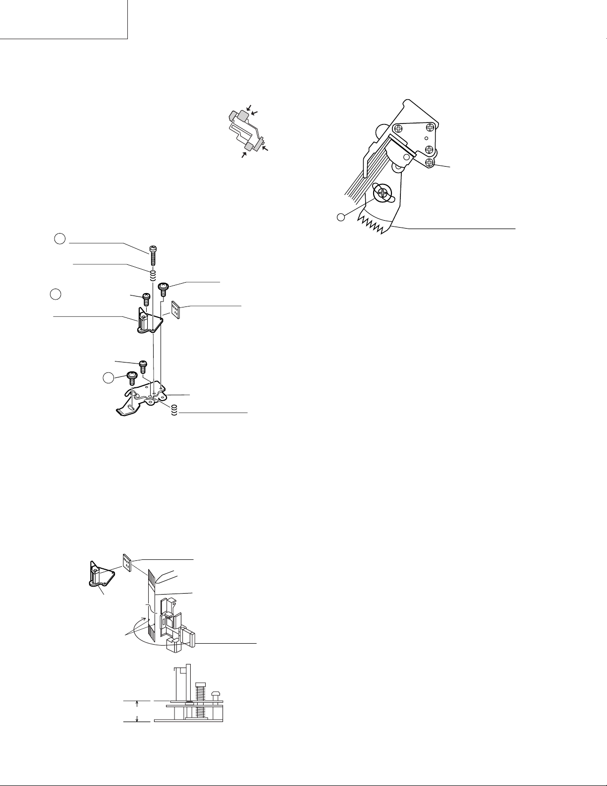
(1) Start and end sensors: Q701 and Q702
Insert the sensor’s projection deep into the upper hole of the holder. Referring to the PWB, fix the sensors tight
enough.
(2) Photocoupler: IC901 and IC902
Refer to the symbol on the PWB and the anode marking of the part.
(3) Cam switches A and B: S704.
Adjust the notch of the part to the white marker of the symbol on the PWB. Do not allow any looseness.
(4) Take-up and supply sensors: D707 and D706.
Be careful not to confuse the setting direction of the parts in reference to the symbols on the PWB. Do not allow any
looseness.
1. SPECIFICATIONS
Format: VHS PAL/MESECAM/NTSC standard (except VC-A60)
VHS PAL/SECAM/MESECAM/NTSC standard (VC-A60)
Video recording system: Rotary, slant azimuth two heads helical scan system
Video signal: PAL colour or monochrome (CCiR system B/G) signals
Maximum Recording/playing time: 240 minutes max. with SHARP E-240 tape at SP mode)
480 minutes max. with SHARP T-160 tape (NTSC: EP mode)
Tape width: 12.7mm
Tape speed: 23.39/33.53 mm/s (PAL/NTSC : SP mode)
11.70/16.67 mm/s (PAL/NTSC: LP mode)
7.79/11.12 mm/s (PAL/NTSC: EP mode)
Antenna: 75 ohm unbalanced
RF converter output signal: UHF Channel E21-E69 (preset to E60)
Power requirement: AC110-240V, 50/60Hz
Power consumption: Approx. 10W (VC-A10/A10S,VC-A50/A50S/A50S(B)/A500/A60)
Approx. 12W (VC-A75)
Approx. 13W (VC-A80S)
Operating temperature: 5°C to 40°C
Storage temperature: –20°C to 60°C
VIDEO Output: 1.0 Vp-p, 75 ohm
AUDIO Output: Line -8 dBs/1k ohm
Weight: Approx. 2.3 kg
Dimensions: 360 mm (W) x 232 mm (D) x 92 mm (H)
Accessories included: 75 ohm coaxial cable
Operation manual
Infrared remote control
Battery
Schematic Diagram (VC-A500)
As part of our policy of continuous improvement, we reserve the
right to alter design and specifications without notice.
Note: The antenna must correspond to the new standard DIN 45325
(IEC 169 — 2) for combined UHF/VHF antenna with 75 ohm connector.
2
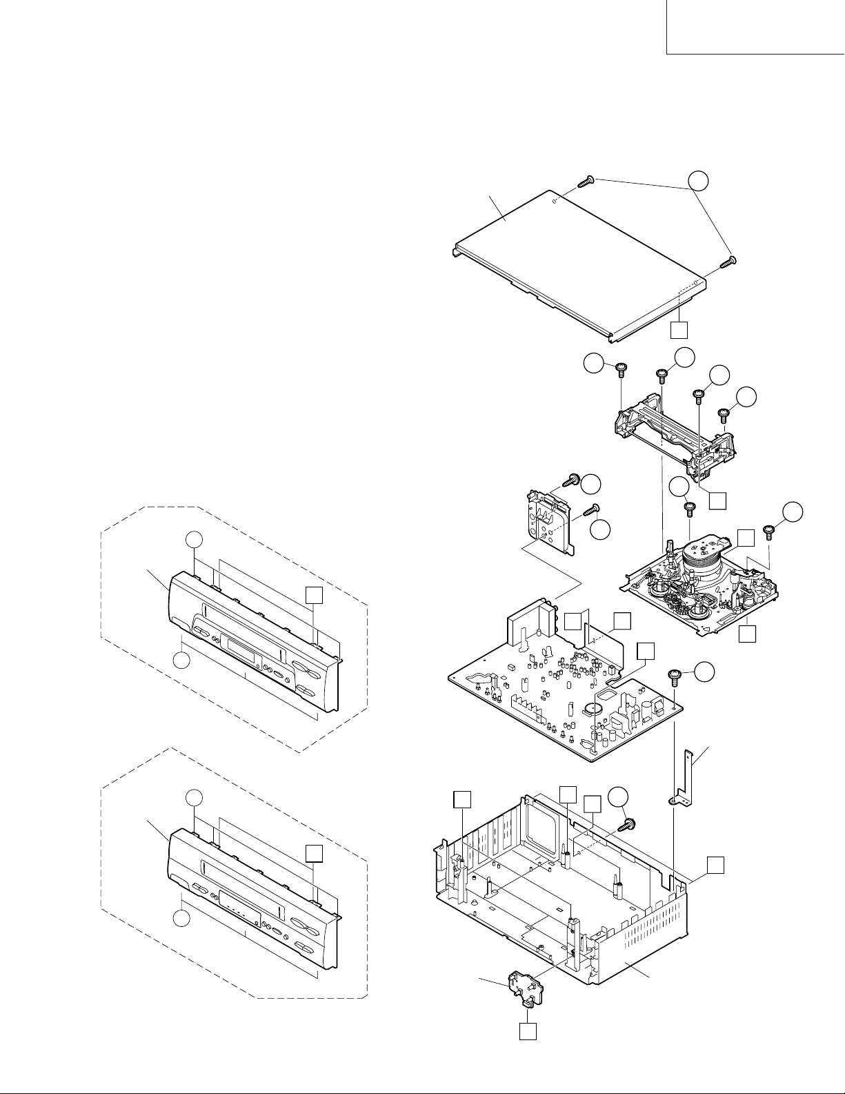
2. DISASSEMBLY AND REASSEMBLY
2-1 DISASSEMBLY OF MAJOR BLOCKS
TOP CABINET : Remove 2 screws 1.
FRONT PANEL : Remove 2 screws 2 and 7 clips 3.
MECHANISM/ : Remove 2 screw 4, 2 screws 5.
MAIN PWB Remove 2 screws 6 with antenna
terminal cover. Remove 1 screw 7
with top cabinet fix angle.
TOP CABINET
VC-A10/A10S/A500
VC-A50/A50S/A50SB
VC-A60/A75/A80S
1
C
VC-GH61GM/SM
FRONT PANEL
2
6
3
B
3
6
A
A
4
2
4
5
B
5
A
E
D
7
TOP CABINET
FIX ANGLE
FRONT PANEL
3
B
3
OPERATION PWB
VC-GH611GM/SM
B
E
D
4
A
C
MAIN FRAME
3
VC-A10/A10S/A500
VC-A50/A50S/A50SB
VC-A60/A75/A80S
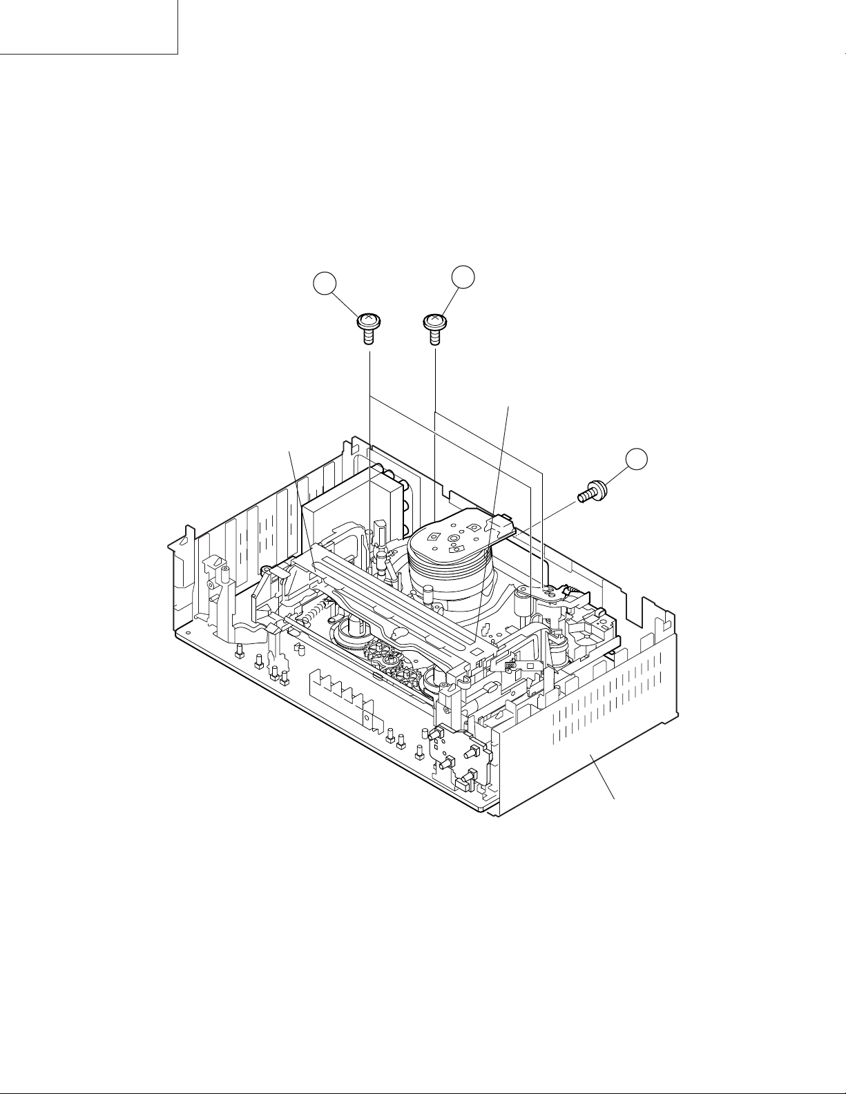
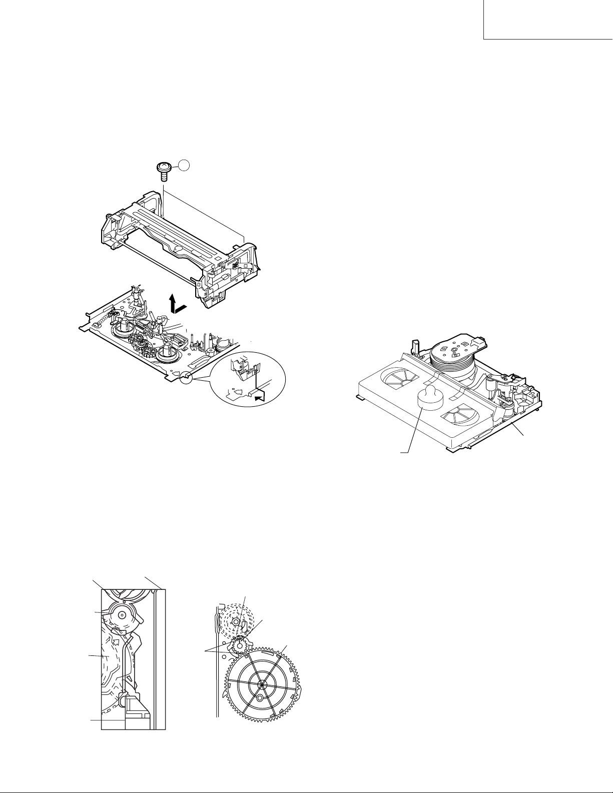
2-2 DISASSEMBLING THE MECHANISM
1. When removing the mechanism from the set.
Remove the screw 2 which connecting the PWB and
the mechanism.
Remove the screw 4 which connecting mechanism and
main frame.
Take out vertically the mechanism so that it does not
damage the adjacent parts.
3
CASSETTE
HOUSING
2. Removing the mechanism and cassette housing.
Remove 2 screws 3 fixing the cassette housing to the
mechanism, and remove the cassette housing.
4
MECHANISM CHASSIS
2
MAIN FRAME
4
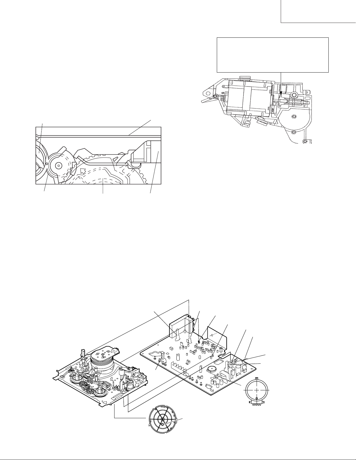
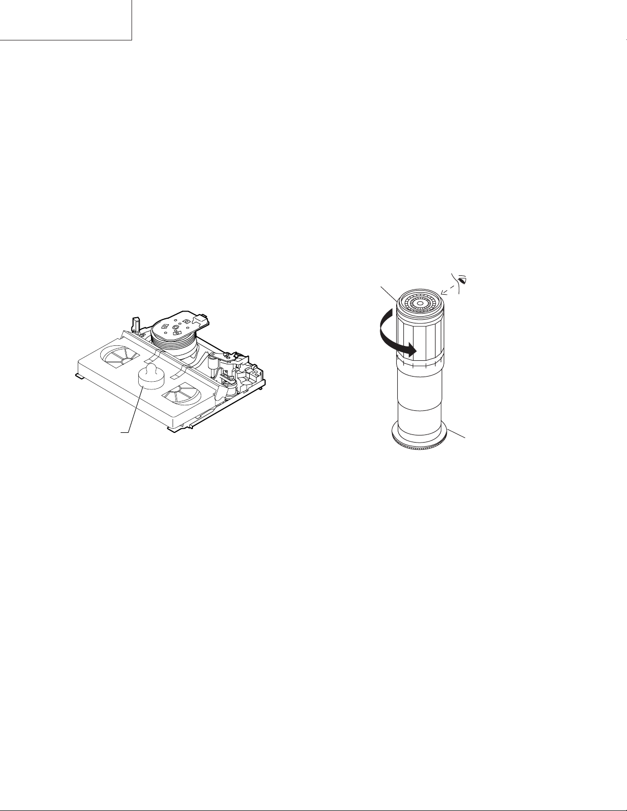
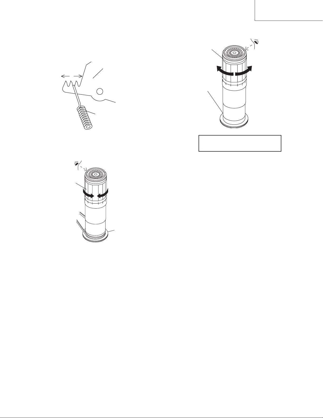
2-3 CARES WHEN REASSEMBLING
Rotate the flange of worm gear by using thin stick.
CW • • • Loading direction
CCW • • • Ejection direction
Note:
Be careful not to damage the gear of worm gear and
worm wheel gear. It miight cause a strange sound.
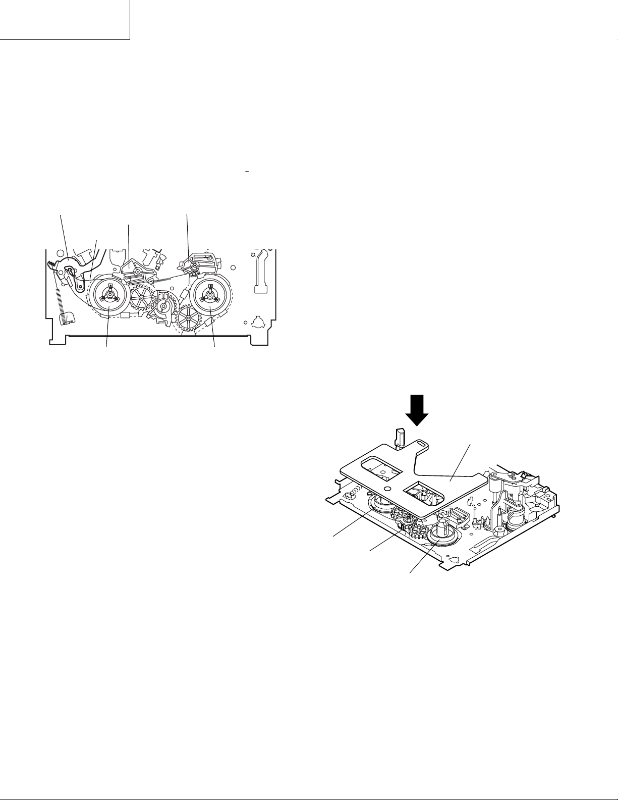
INSTALLING THE CASSETTE HOUSING
When the cassette housing is installed on the mechanism,
the initial setting is essential condition.
There are two initial setting methods, namely electrical and
mechanical.
1. Electrical initial setting
So as to perform initial setting of mechanism execute the
Step 1 of Installation of cassette housing. After ascertaining
the return to the initial setting position install the cassette
housing. (Conditions: When mechanism and PWB have
been installed)
Pinch Drive Cam
Synchro Gear
Master cam
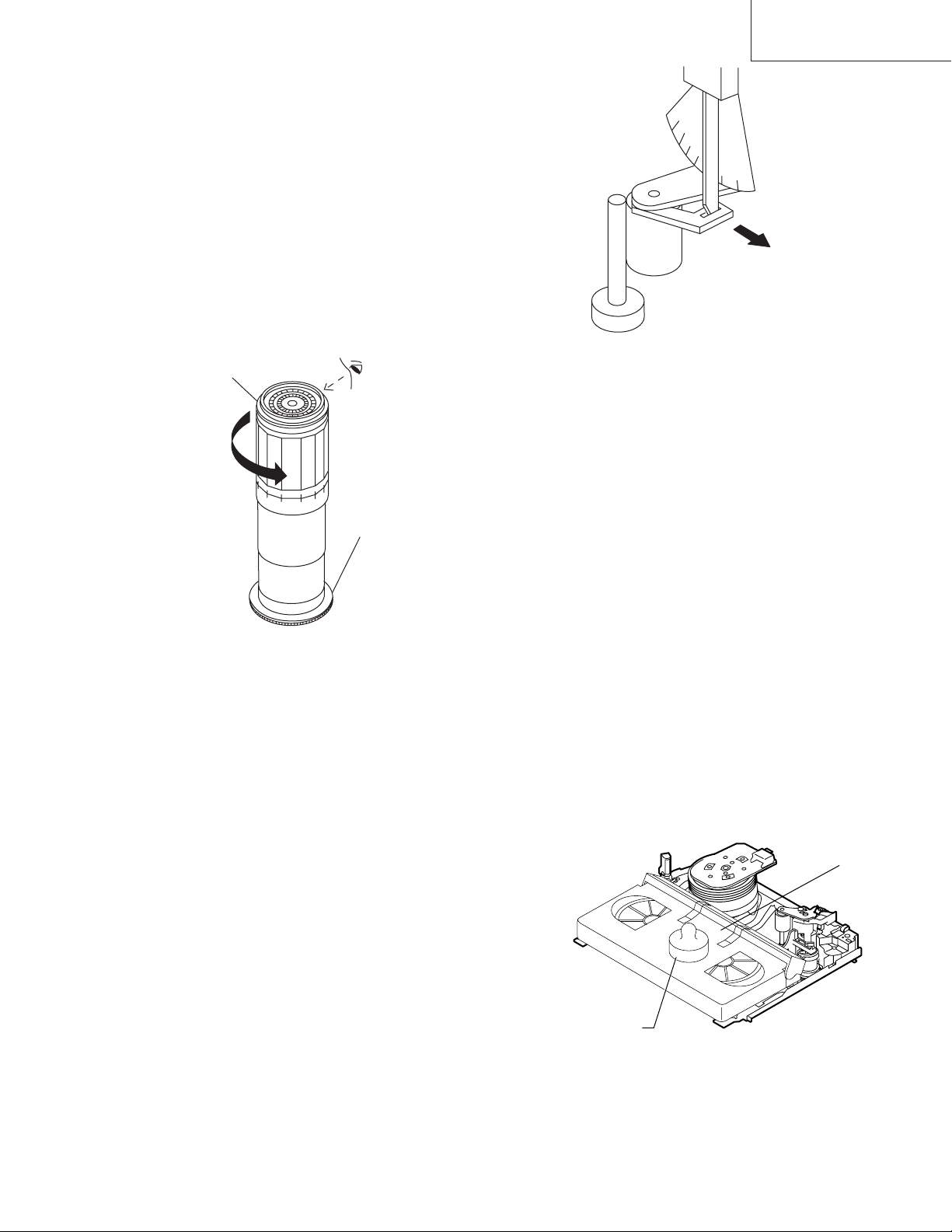
2. Mechanical initial setting
• Rotate the worm gear by pushing the flange manually until
return to initial position.
Main Chassis
Drive Lever
VC-A10/A10S/A500
VC-A50/A50S/A50SB
VC-A60/A75/A80S
• When apply power supply to rotate the loading motor,
please remove/unsolder at least one terminal wire.
• If voltage applied to loading motor without diconnecting
the terminal wire, there is a possibility the capstan motor
IC will damage.
• The maximum applied voltage is 9V. If more than 9V,
there is apossibility the mechanism will damage.
• After ascertaining the return to the initial set position
install the cassette housing in the specified position. (This
method is applied only for the mechanism.)
INSTALLING THE MECHANISM ON PWB
Lower vertically the mechanism, paying attention to the
mechanism edge mode SW position, (Set the mode SW
position to 270° and make sure the master cam position
hole also in 270° position) and install the mechanism with
due care so that the parts are not damaged.
* Please make sure to insert correctly.
If not, strange moving will occur and will couse mecha-
nism damage.
END SENSOR
END TIP SW
PARTS WHICH NEED PARTICULAR CARE
When installing the mechanism chassis on the PWB unit,
take care so as to prevent deformation due to contact of
mechanism chassis with REC TIP SW.
AE CONNECTOR
AH CONNECTOR
AA CONNECTOR
AD CONNECTOR
AC CORD
VC-A50 only
START SENSOR
90°
0°
This positioning hole
should be at front side.
180°
270°
MODE SW
MASTER CAM POSITION
5
VC-A10/A10S/A500
VC-A50/A50S/A50SB
VC-A60/A75/A80S
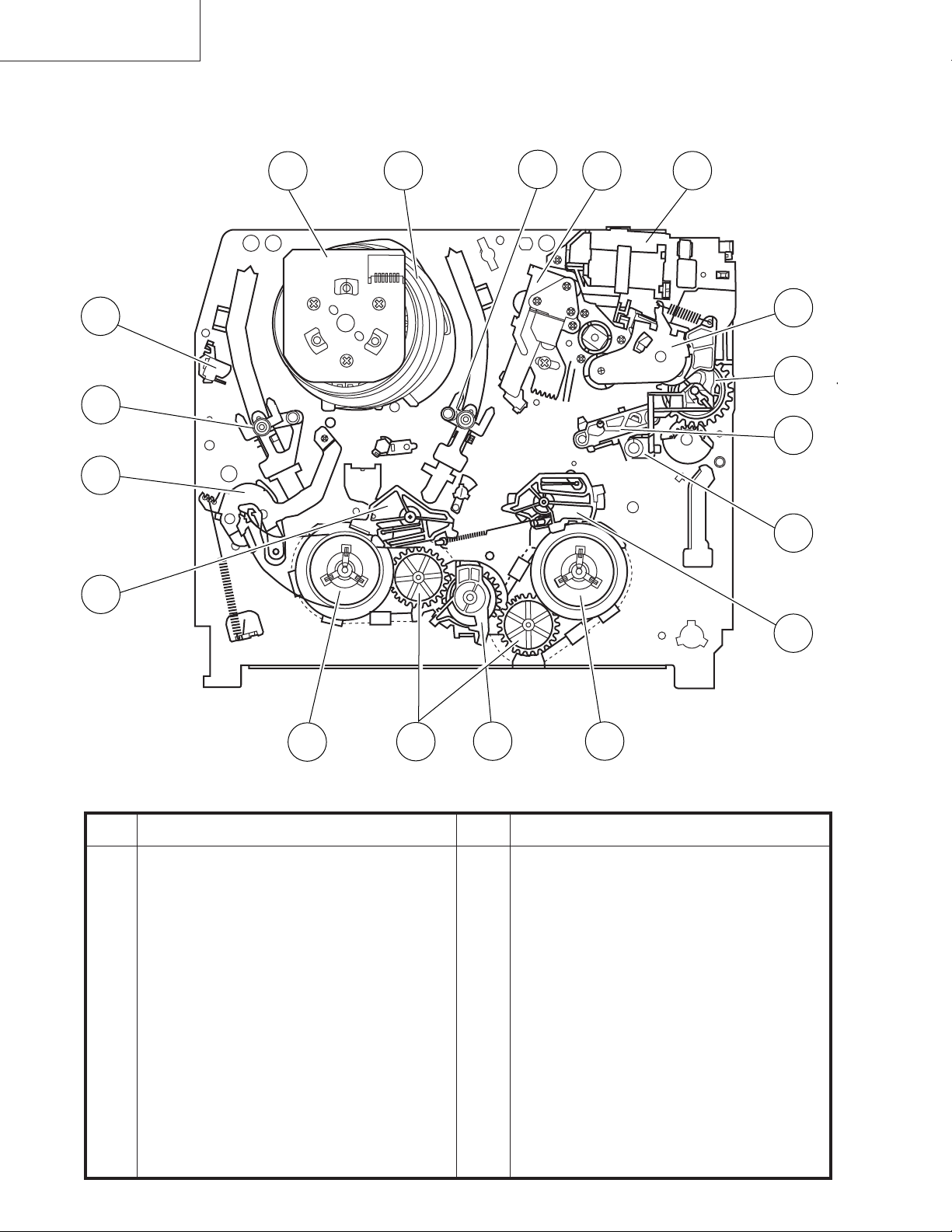
3. FUNCTION OF MAJOR MECHANICAL PARTS (TOP VIEW)
17
15
1
18
10
16
14
9
2
11
3
5
7
6
No. Function
1 Full erase head
2 Supply pole base ass’y
3 Tension arm
4 Idler wheel ass’y
5 Open guide
6 Supply reel disk
7 Supply main brake
12
4
13
No. Function
11 Reverse guide lever ass’y
12 Reel relay gear
13 Take-up reel disk
14 Pinch roller lever ass’y
15 Drum ass’y
16 Loading motor block
17 Drum driver motor
8
8 Take-up main brake
9 Pinch drive cam
10 A/C head ass’y
18 Take-up pole base ass’
6
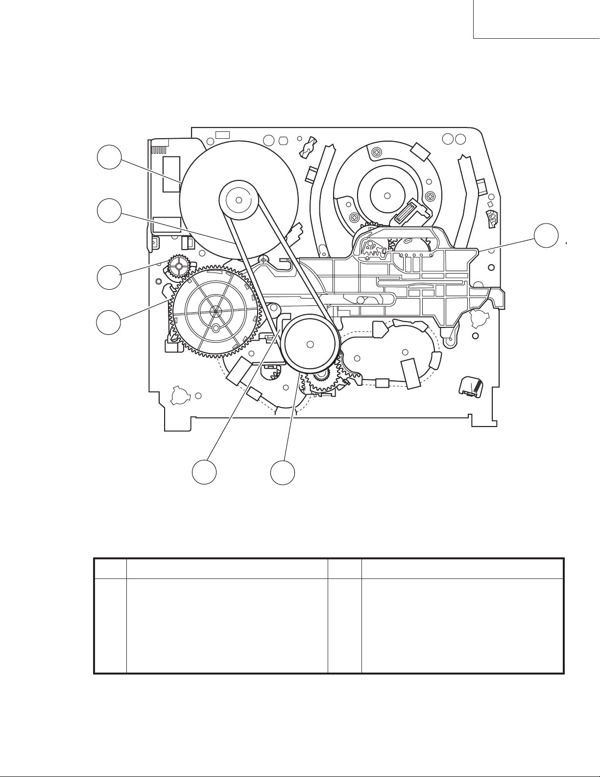
FUNCTION OF MAJOR MECHANICAL PARTS (BOTTOM VIEW)
(except VC-A50S)
21
22
VC-A10/A10S/A500
VC-A50/A50S/A50SB
VC-A60/A75/A80S
19
20
23
24
25
No. Function
19 Syncro Gear
20 Master cam
21 Capstan D.D. motor
22 Reel belt
No. Function
23 Clutch lever
24 Limiter pulley ass’y
25 Shifter
7
VC-A10/A10S/A500
VC-A50/A50S/A50SB
VC-A60/A75/A80S
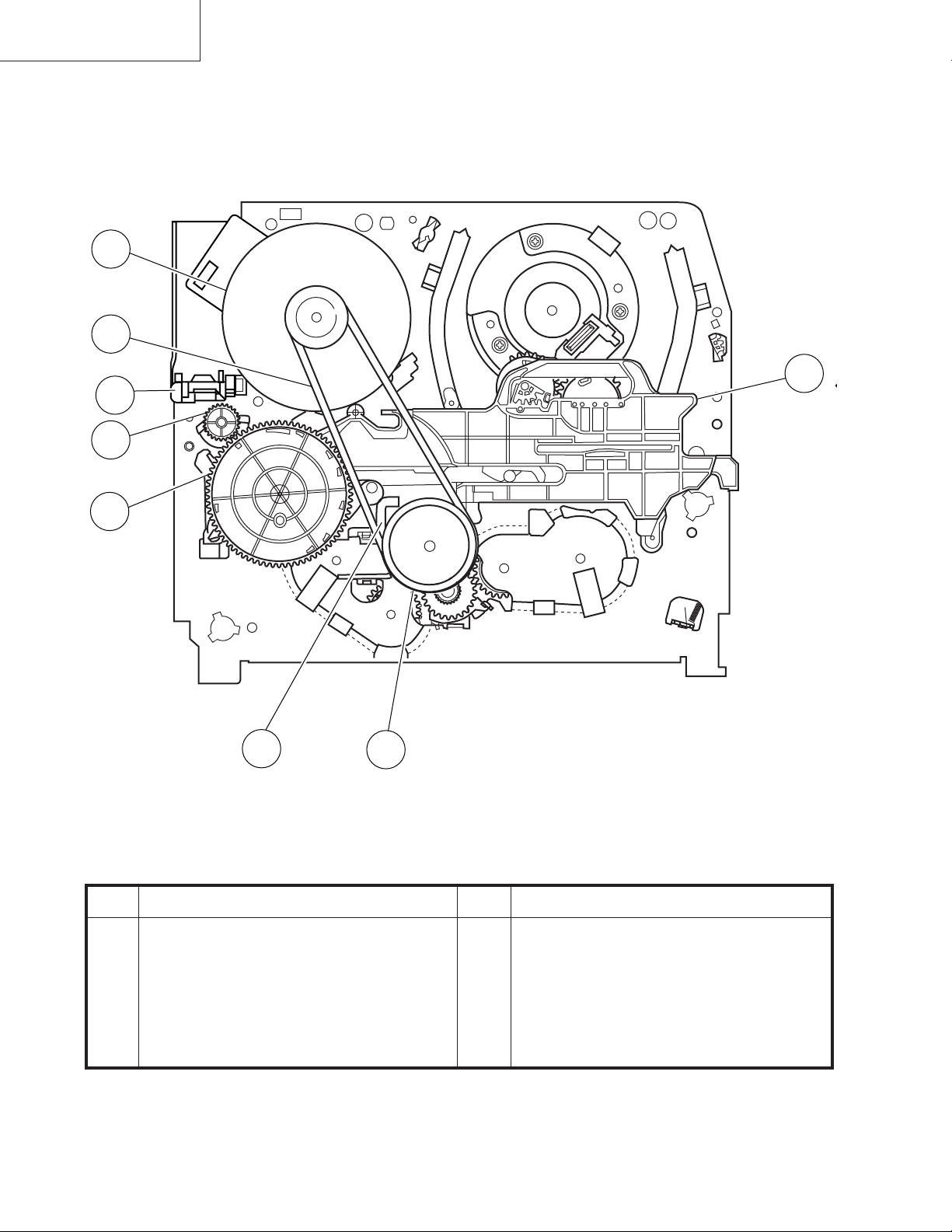
FUNCTION OF MAJOR MECHANICAL PARTS (BOTTOM VIEW)
(VC-A50S)
21
22
26
19
20
23
24
25
No. Function
19 Syncro Gear
20 Master cam
21 Capstan D.D. motor
22 Reel belt
No. Function
23 Clutch lever
24 Limiter pulley ass’y
25 Shifter
26 DM/LM FFC Holder
8
VC-A10/A10S/A500
VC-A50/A50S/A50SB
VC-A60/A75/A80S
4. ADJUSTMENT, REPLACEMENT AND ASSEMBLY OF MECHANICAL UNITS
The explanation given below relates to the on-site general service (field service) but it does not relates to the adjustment
and replacement which need high-grade equipment, jigs and skill. For example, the drum assembling, replacement and
adjustment service must be performed by the person who have finished the technical courses.
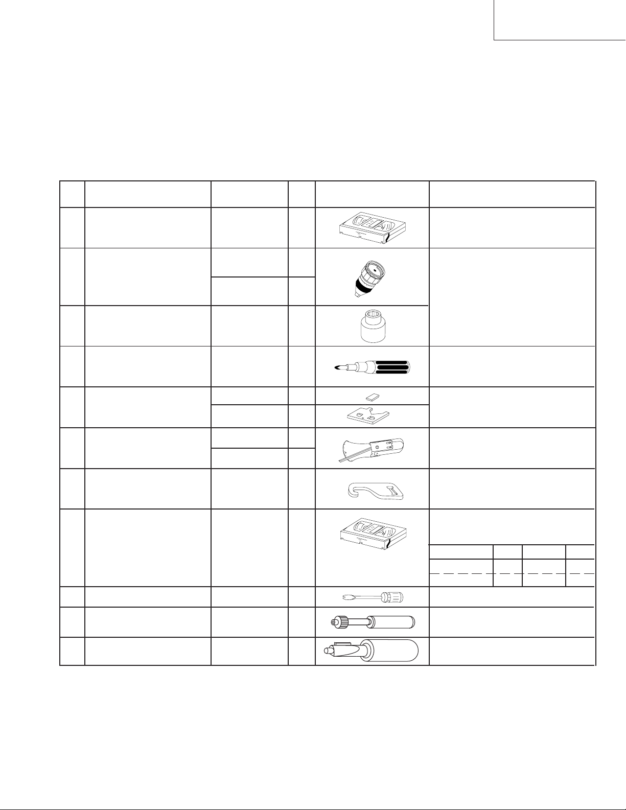
4-1 MECHANISM CONFIRMATION ADJUSTMENT JIG
So as to perform completely the mechanism adjustment prepare the following special jigs. So as to maintain the initial
performance of the machine the maintenance and check are necessary. Utmost care must be taken so that the tape is
not damaged. If adjustment needs any jig, be sure to use the required jig.
No. Jig ltem Part No. Code Configuration Remarks
This cassette torque meter is used for check-
1. Torque Cassette Meter JiGVHT-063 CZ
JiGTG0090 CM
2.
Torque Gauge
JiGTG1200 CN
3. Torque Gauge Head JiGTH0006 AW
ing and adjusting the torque of take-up for
measuring tape back tension.
These Jigs are used for checking
and adjusting the torque of take-up
and supply reel disks.
4. Torque Driver JiGTD1200 CB
Master Plane Jig and
Reel Disk Height
5.
Adjusting Jig
JiGRH0002 BR
JiGMP0001 BY
JiGSG2000 BS
Tension Gauge
6.
JiGSG0300 BF
Pinch pressing force
7. JiGADP003 BK
measuring jig
8.
Alignment Tape
Guide roller height
9. JiGDRiVERH-4 AP
adjustment driver
X value adjustment
10. JiGDRiVER-6 BM
gear driver
Tension Pole
11. JiGHMEC-M005
Adjustment Driver
VROCPSV CK
When fixing any part to the threaded
hole using resin with screw, use the
jig. (Specified torque 5 kg)
These Jigs are used for checking
and adjusting the reel disk height.
There are two gauges used for the
tension measurements, 300 g and
2.0 kg.
This Jig is used with the tension
gauge. Rotary transformer clearance
adjusting jig.
These tapes are especially used for
electrical fine adjustment.
Video Audio HiFi Audio Track
625 Monoscope 7k — 49µm
PAL Colour Bar 1k — 49µm
This screwdriver is used for adjusting the
guide roller height.
For X value adjustment
This Jig is used for adjustment
of tension pole.
9
VC-A10/A10S/A500
VC-A50/A50S/A50SB
VC-A60/A75/A80S
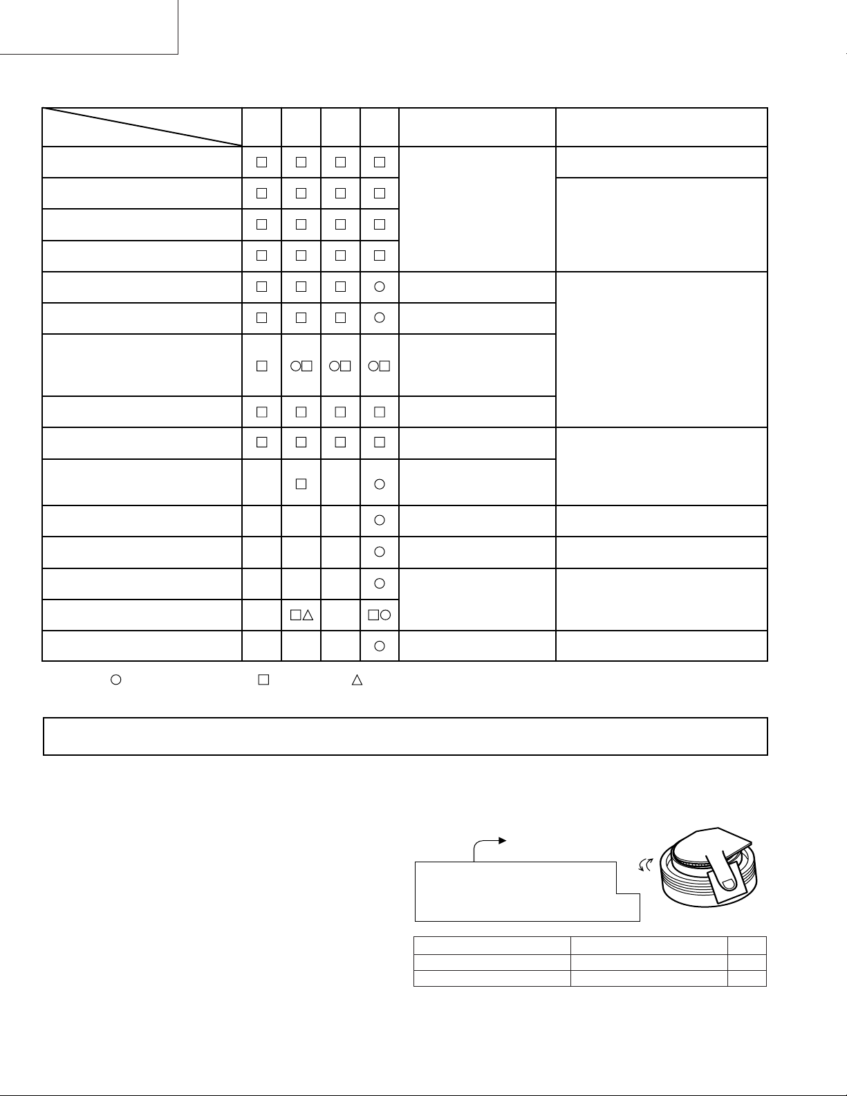
4-2 MAINTENANCE CHECK ITEMS AND EXECUTION TIME
Perform the maintenance with the regular intervals as follows so as to maintain the quality of machine.
Possible symptom
encountered
Abnormal rotation or significant
vibration requires replacement.
Parts
Guide roller ass’y
Maintained
500
hrs.
1000
hrs.
1500
hrs.
2000
hrs.
Remarks
Sup guide shaft
Reverse guide
Slant pole on pole base
Full erase head
A/C head
Upper and lower drum ass’y
Capstan D.D. motor
Pinch roller
Reel belt
Tension band ass’y
Loading motor
Idler ass’y
Limiter pulley
Lateral noises Head
occasionally blocked
Colour and beating
Small sound or sound
distortion
Poor S/N ratio, no colour
Poor flatness of the
envelope with alignment
tape
No tape running,
uneven colour
No tape running, tape
slack
No tape running, tape
slack, no fast forward/
rewind motion
Screen swaying
Cassette not loaded or
unloaded
No tape running, tape
slack
Clean tape contact part with the
specified cleaning liquid.
Clean tape contact area with the
specified cleaning liquid.
Clean rubber and rubber contact
area with the specified cleaning
liquid.
Supply/take-up main brake levers
Tape slack
NOTE : Part replacement. : Cleaning : Apply grease
<Specified> Cleaning liquid Industrial ethyl alcohol
* This mechanism does not need electric adjustment with variable resistor. Check parts. If any deviation is found,
clean or replace parts.
Video head cleaning procedure
1. Apply one drop of cleaning liquid to the cleaning paper with the baby oiler.
2. Gently press the cleaning paper against the video head to fix your finger, and move the upper drum so that each head
is passed to and fro 5 times (do not move the cleaning paper).
3. Wipe with the dry cleaning paper.
Notes :
• Use the commercially available ethanol of Class 1 as
cleaning liquid.
• Since the video head may be damaged, do not move up
and down the cleaning paper.
Gently press the cleaning paper to
fix with your finger, and rotate the
upper drum to clean.
Move to and fro 5 times for each head.
(Do not move the cleaning paper.)
Rotate the upper drum
with one hand.
• Whenever the video head is cleaned, replace the cleaning paper.
• Do not apply this procedure for the parts other than the
video head.
Parts Code Description Code
ZPAPRA56-001E Cleaning Paper AW
ZOiLR-02-24TE Babe Oiler (Spoit) AH
10
4-3 REMOVING AND INSTALLING THE CAS-
SETTE HOUSING
• Removal
1. In the cassette removing mode, remove the cassette.
2. Unplug the power cord.
3. Remove in the following numerical order.
a) Remove two screws 1.
b) Pull and circle the drive lever and pull up the cassette
housing control.
1
VC-A10/A10S/A500
VC-A50/A50S/A50SB
VC-A60/A75/A80S
2. Install in the reverse order of removal.
Notes
1. In the case when you use the magnet screw driver, never
approach the magnet driver to the A/C head, FE head,
and drum.
2. When installing or removing, take care so that the
cassette housing control and tool do not contact the
guide pin or drum.
3. After installing the cassette housing control once perform cassette loading operation.
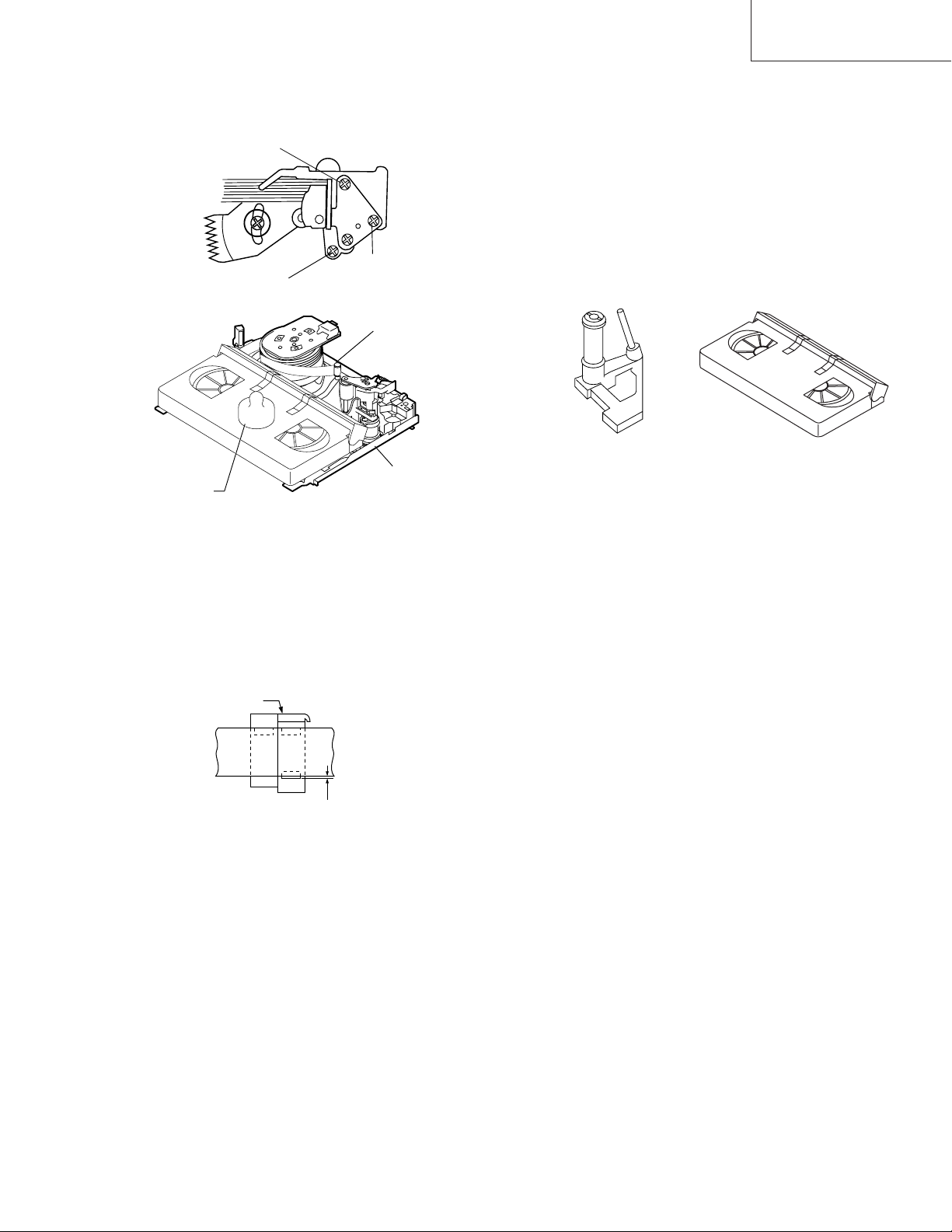
4-4 TO RUN A TAPE WITHOUT THE CASSETTE
HOUSING CONTROL ASSEMBLY
1. Remove the full-surface panel.
2. Short-circuit between TP803 and TP802.
3. Plug in the power cord.
4. Turn off the power switch.
(The pole bases move into U.L.position.)
5. Open the lid of a cassette tape by hand.
6. Hold the lid with two pieces of vinyl tape.
7. Set the cassette tape in the mechanism chassis.
8. Stabilize the cassette tape with a weight (500g) to
prevent floating.
Figure 4-1.
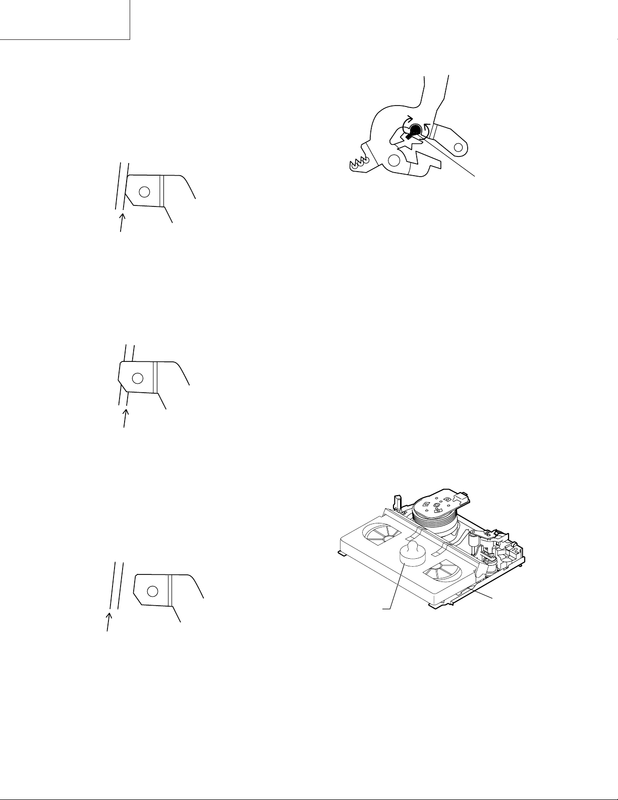
• Reassembly
1. Before installing the cassette housing control, shortcircuit between TP803 and TP802 provided at main
PWB, press the eject button. The master cam turns and
stop in eject position. Fit the drive lever to master cam
through main chassis, push down and slide the drive
lever towards to master cam.
*Eject position: Pinch Drive Cam positioning hole parallel to center of Synchro Gear (Synchro gear marking
line). Synchro Gear positioning mark parallel to center
of master cam.
Pinch Drive
Cam
Synchro
Gear
Master
cam
Main chassis
Phase
matching
Hole of Pinch
drive cam.
Line of
synchro
gear.
Master cam
500g
Mechanism chassis
Weight to prevent
float (500g)
Figure 4-3.
9. Turn on the power switch.
10. Perform running test.
Note:
The weight should not be more than 500g.
To take out the cassette tape.
1. Turn off the power switch.
2. Take out the cassette tape.
Drive
Lever
From top view
From Bottom View
Figure 4-2.
11
VC-A10/A10S/A500
VC-A50/A50S/A50SB
VC-A60/A75/A80S
4-5 REEL DISK REPLACEMENT AND HEIGHT
CHECK
• Removal
1. Remove the cassette housing control assembly.
2. Remove the Supply/Take-up main brake ass’y.
3. Remove tension band from the tension arm ass’y.
4. Remove the reel disk.
Note:
Take care so that the tension band ass’y and main brake
ass’y are not deformed.
Tension arm ass’y
Ten
Tension band
ass’y
Supply main brake
Take-up main brake ass’y
Notes:
1. When installing the reel disk, take due care so that the
tension band ass’y is not deformed and grease does no
adhere.
2. Do not damage the Supply main brake ass’y. Be careful
so that grease does not adhere to the brake surface.
• Reassembly (Take-up reel disk)
1. Clean the reel disk shaft and apply grease (SC-141) to
it.
2. Align the phase of the reel disk to that of the reel relay
gear and to install a new take-up reel disk onto the shaft.
3. Check the reel disk height and reassemble the take-up
main brake ass’y.
Note:
1. Take care so that the Take-up main brake ass’y is not
damaged. Take care so that grease does not adhere the
brake surface.
2. After reassembly, check the video search rewind back
tension (see 4-10), and check the brake torque (see 4-
14).
Take-up reel diskSupply reel disk
• Reassembly (Supply reel disk)
1. Clean the reel disk shaft and apply grease (SC-141) to
it.
2. Match the phases of reel disk and reel relay gear, and set
the new reel disk.
3. After checking the reel disk height, wind the tension
band ass’y around the reel disk, and hook to tension arm
ass’y.
4. Assemble the Supply main brake ass’y.
• Height checking and adjustment
Note:
1. Set the master plane with due care so that it does not
contact the drum.
2. When putting the master plane, shift the reverse guide
a little in the loading direction. Care must be taken since
excessive shift results in damage.
Master plane
Supply reel disk
Cassette lock
release shaft
Take-up reel disk
Figure 4-4.
Note:
• Check that the reel disk is lower than part A but higher
than part B. If the height is not correct, readjust the reel
disk height by changing the poly-slider washer under the
reel disk.
12
Note:
Whenever replacing the reel disk, perform the height checking and adjustment.
Master plane
10 ± 0.2mm
Reel disk
Reel disk
Reel disk height
adjusting jig
Mechanism chassis
A
B
Figure 4-5.
4-6 CHECKING AND ADJUSTMENT OF TAKE-
UP TORQUE IN FAST FORWARD MODE
• Remove the cassette housing control assembly.
• After short-circuiting between TP803 and TP802
provided at main PWB, plug in the power cord.
• Setting
1. Set a torque gauge to zero on the scale. Place it on the
take-up reel disk.
2. Press the FF button.
3. To calculate the remaining capacity of the play back
mode, slowly rotate the supply reel disk, and then shift
it into the forward mode.
VC-A10/A10S/A500
VC-A50/A50S/A50SB
VC-A60/A75/A80S
Notes:
1. Hold the torque gauge by hand so that it is not moved.
2. Do not keep the reel disk in lock state. Do not allow longtime measurement.
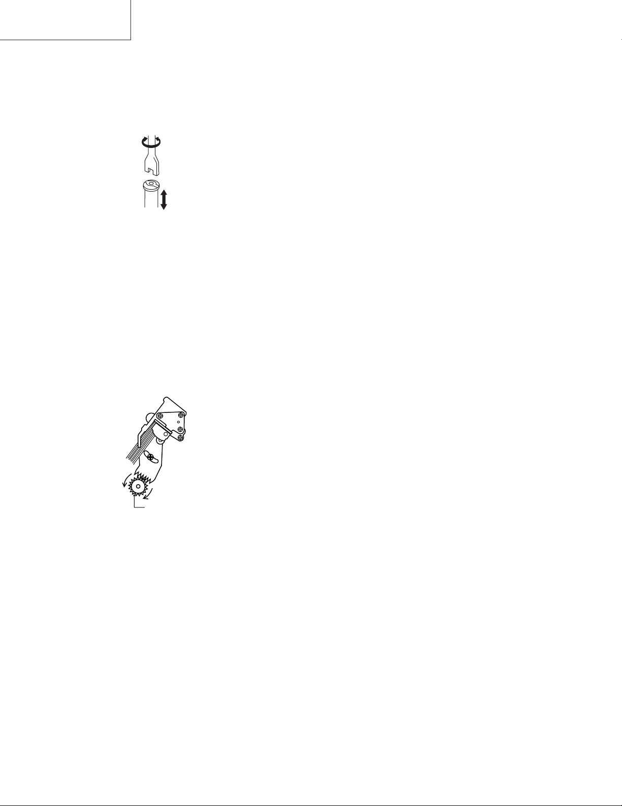
4-7 CHECKING AND ADJUSTMENT OF TAKE-
UP TORQUE IN REWIND MODE
• Remove the cassette housing control assembly.
• After short-circuiting between TP803 and TP802
provided at main PWB, plug in the power cord.
• Setting
1. Set a torque gauge to zero on the scale. Place it on the
supply reel disk.
2. Press the rewind button.
3. To calculate the remaining capacity, slowly rotate the
take-up reel disk, and then shift it into the rewind mode.
• Checking
1. Turn the torque gauge slowly (one rotation every 2 to 3
seconds) by hand in the CCW direction.
2. Make sure that the indication of torque gauge is not less
than 30mN·m (306gf·cm).
Torque gauge 3
• Checking
1. Turn the torque gauge slowly (one rotation every 2 to 3
seconds) by hand in the CW direction.
2. Make sure that the indication of torque gauge is not less
than 30mN·m (306gf·cm).
Torque gauge
30mN·m (306gf·cm)
or more
Idler ass’y
CW
The gauge is held at
its maximum value.
(Red mark)
Figure 4-6.
• Adjustment
1. If the FF winding-up torque is less than the specified
value, clean the capstan D.D. pulley, reel belt, and
limiter pulley with cleaning liquid, and check again.
2. If the torque is less than the set value, replace the reel
belt.
30mN·m (306gf·cm)
or more
CCW
The gauge is held at
its maximum value.
(Red mark)
Supply reel disk
Idler ass’y
Figure 4-7.
• Adjustment
1. If the rewind winding-up torque is less than the specified
value, clean the capstan D.D. pulley, reel belt, and
limiter pulley with cleaning liquid, rewind again, and
check the winding-up torque.
2. If the winding-up torque is still out of range, replace the
drive belt.
13
VC-A10/A10S/A500
VC-A50/A50S/A50SB
VC-A60/A75/A80S
Notes:
1. Hold the torque gauge by hand so that it is not moved.
2. Do not keep the reel disk in lock state. Do not allow longtime measurement.
4-9 CHECKING AND ADJUSTMENT OF TAKE-
UP TORQUE IN VIDEO SEARCH REWIND
MODE
• Remove the cassette housing control assembly.
4-8 CHECKING AND ADJUSTMENT OF TAKE-
UP TORQUE IN RECORD/PLAYBACK
MODE
• Remove the cassette housing control assembly.
• After short-circuiting between TP803 and TP802
provided at main PWB, plug in the power cord.
• Turn off the power switch.
• Open the cassette torque meter lid, and fix it with
tape.
• Load the cassette torque meter into the unit.
• Put the weight (500g) on the cassette torque meter.
• Turn on the power switch.
• Press the picture record button, and set LP picture
record mode (x2).
Set value LP 6.9
+2.0
mN⋅m (70
–2.5
500g
+20
–25
gf⋅cm)
• After short-circuiting between TP803 and TP802
provided at main PWB, plug in the power cord.
• Setting
Press the playback button and rewind button to set the
video search rewinding mode.
• Checking
Place the torque gauge on the supply reel disk, and turn it
counterclockwise very slowly (one rotation every 1 to 2
seconds) and check that the torque is within the set value
14.1 ± 3.5mN⋅m. (144 ± 35gf⋅cm)
Torque gauge
CCW
Cassette torque meter
Figure 4-8.
• Checking
1. Make sure that value is within the setting 6.9 mN·m
+20
(70 gf·cm).
–25
+2.0
–2.5
2. The winding-up torque fluctuates due to variation of
rotation torque of limiter pulley ass’y. Read the center
value of fluctuation as setting.
3. Set the LP record mode (x2) and make sure that the
winding-up torque is within setting.
• Adjustment
If the playback winding-up torque is not within the setting,
replace the limiter pulley assembly.
Note:
When the torque cassette is set, put a weight (500g) to
prevent rise.
When the cassette torque meter is taken out.
Turn off the power switch.
Supply reel disk
Figure 4-9.
Note:
Surely put the torque gauge on the reel disk to measure. If
the torque gauge is raised, accurate measurement is
impossible.
• Adjustment
If the rewinding playback winding-up torque is not within the
setting, replace the limiter pulley assembly.
Note:
The winding-up torque fluctuates due to variation of rotation torque of supply reel disk. Read the center value of
fluctuation as setting.
14
4-10 CHECKING THE VIDEO SEARCH REWIND
500g
Weight to prevent
float (500g)
(E-180)
BACK TENSION
• Remove the cassette housing control assembly.
VC-A10/A10S/A500
VC-A50/A50S/A50SB
VC-A60/A75/A80S
• After short-circuiting between TP803 and TP802
provided at main PWB, plug in the power cord.
• Checking
1. After pressing the play button, press the rewind button,
and set the video search rewind mode.
2. Place the torque gauge on the take-up reel disk, and turn
it counterclockwise very slowly (one rotation every 2 to
3 seconds) and check that the torque is within the set
value 3.7 ± 1.5mN⋅m (38 ± 15gf⋅cm).
Torque gauge
CCW
Take-up reel disk
Pinch roller
Capstan shaft
Tension gauge adapter
Tension gauge
900 — 1,200gf
Figure 4-11.
4-12 CHECKING AND ADJUSTMENT OF
TENSION POLE POSITION
∗∗
∗ Checking can be perform with or without
∗∗
cassette housing control.
• Remove the cassette housing control assembly.
• After short-circuiting between TP803 and TP802 provided at main PWB, plug in the power cord.
Figure 4-10.
Notes:
Set the torque gauge securely on the take-up reel disk.
If it is not secure, the measurement will be incorrect.
4-11 CHECKING THE PINCH ROLLER
PRESSURE
∗∗
∗ Checking can be perform with or without
∗∗
cassette housing control.
• Remove the cassette housing control assembly.
• After short-circuiting between TP803 and TP802 provided at main PWB, plug in the power cord.
• Checking
Press the play button to set the playback mode.
1. Detach the pinch roller from the capstan shaft.
Do not separate excessively. Or the pinch lever and
pinch double action lever may disengage.
2. Engage the tension gauge adapter with the pinch roller
shaft, and pull in the arrow direction.
3. Gradually return the pinch roller, and measure the pulling force when the pinch roller contacts the capstan
shaft.
4. Make sure that the measured value is within setting
change to 9.8 ± 2N (1.0 ± 0.2kgf).
• Setting (without cassette housing control)
1. Turn off the power switch.
2. Open the cassette tape (E-180), and fix with tape.
3. Set the cassette tape in loading state.
4. Put the weight (500g) on the cassette tape.
5. Turn on the power switch.
6. Make the adjustment with the beginning of a E-180 tape.
• Setting (with cassette housing control)
1. Insert cassette tape (E-180).
2. Make the adjustment with the beginning of a E-180
tape.
Figure 4-12.
15
VC-A10/A10S/A500
VC-A50/A50S/A50SB
VC-A60/A75/A80S
• Checking
1. Set a cassette tape, push the REC button to place the
unit in the SP record mode. Now check the tension pole
position.
2. Visually check to see if the position of the tension pole is
within the 0 mm from the left side line.
+ 0.5
– 0.2
Standard A = 0 mm
A
+ 0.5
— 0.2
Tension pole adjustment driver adjusting direction
CCW
CW
Tension pole
adjustment
driver
Figure 4-16.
Make the adjustment with the beginning of a E-180 tape.
Figure 4-13.
At left side from the reference line. (A).
A
Figure 4-14.
Insert the tension pole adjustment driver to main chassis
hole, and rotate clockwise.
At right side from the reference line. (A).
4-13 CHECKING AND ADJUSTMENT OF
RECORD/PLAYBACK BACK TENSION
∗∗
∗ Checking can be perform with or without
∗∗
cassette housing control.
• Remove the cassette housing control assembly.
• After short-circuiting between TP803 and TP802 provided at main PWB, plug in the power cord.
• Setting (without cassette housing control)
1. Turn off the power switch.
2. Open the cassette torque meter and fix with tape.
3. Set the cassette torque meter in loading state.
4. Put the weight (500g) on the cassette torque meter.
5. Turn on the power switch.
• Setting (with cassette housing control)
1. Insert cassette torque meter.
A
Figure 4-15.
Insert the tension pole adjustment driver to main chassis
hole, and rotate counterclockwise.
500g
Cassette torque
Weight to prevent
float (500g)
meter
Figure 4-17.
• Checking
1. Push the REC button to place the unit in the SP record
mode.
2. At this time ascertain that the back tension is within the
setting 3.9 to 5.5mN⋅m (40 to 56gf·cm) by seeing the
indication of torque cassette meter.
16
• Adjustment
1. If the indication of torque cassette meter is lower than
the setting, shift the tension spring engagement to the
part A.
2. If the indication of torque cassette meter is higher than
the setting, shift the tension spring engagement to the
part B.
A
B
Tension arm
Tension spring
VC-A10/A10S/A500
VC-A50/A50S/A50SB
VC-A60/A75/A80S
• Checking the brake torque at the take-up side
Torque gauge
CW
Take-up reel
disk
CCW
Figure 4-18.
4-14 CHECKING THE BRAKE TORQUE
• Checking the brake torque at the supply side
Torque gauge
CCW
CCW: 4.41 ± mN⋅m (45 ± gf⋅cm)
CW: 4.12 ± mN⋅m (42 ± gf⋅cm)
+2.0
–1.5
+1.5
–1.2
Figure 4-19.
• Remove the cassette housing control assembly.
• After short-circuiting between TP803 and TP802
provided at main PWB, plug in the power cord.
CW
Supply reel disk
+20
–15
+15
–12
CCW: 4.41 ± mN⋅m (45 ± gf⋅cm)
CW: 4.12 ± mN⋅m (42 ± gf⋅cm)
+2.0
–1.5
+1.5
–1.2
+20
–15
+15
–12
Figure 4-20.
• Remove the cassette housing control assembly.
• After short-circuiting between TP803 and TP802
provided at main PWB, plug in the power cord.
• Setting
1. Switch from the FF mode to the STOP mode.
2. Disconnect the power cord.
3. Set a torque gauge to zero on the scale. Place it on the
take-up reel disk.
4. Please check Idler gear not contact with reel relay gear
(TU side)
• Checking
1. Turn the torque gauge at a rate of about one turn/2 sec
in the CCW direction/CW direction so that the reel disk
and torque gauge pointer rotates at equal speed and
make sure that the value is within the setting (CCW
direction: 4.41 ± 1mN·m (45 ± gf·cm), CW direction:
+1.5
4.12 ± 1.mN·m (42 to gf·cm).
–1.2
+2.0
–1.5
+15
–12
+20
–15
• Setting
1. Set a torque gauge to zero on the scale. Place it on the
supply reel disk.
2. Switch from the FF mode to the STOP mode.
3. Disconnect the power cord.
4. Please check Idler gear not contact with reel relay gear
(SU side)
• Checking
Turn the torque gauge at a rate of about one turn/2 sec
in the CW direction/CCW direction with respect to the
supply reel disk so that the reel disk and torque gauge
pointer rotate at equal speed, and make sure that the
value is within the setting (CW direction: 4.12 ± mN·m
+15
(42 gf·cm); CCW direction: 4.41 mN·m (45 15gf·cm).
–12
+2.0
–1.5
+1.5
–1.2
+20
–15
2. Adjustment of the brake torque at the supply side and the
take-up side
• Unless the supply side brake torque or take-up side
brake torque is within the setting, clean the felt surface
of reel disk (supply, take-up) brake lever, check again
the brake torque.
• If value cannot be set within the setting yet, replace the
main brake ass’y or main brake spring.
17
VC-A10/A10S/A500
VC-A50/A50S/A50SB
VC-A60/A75/A80S
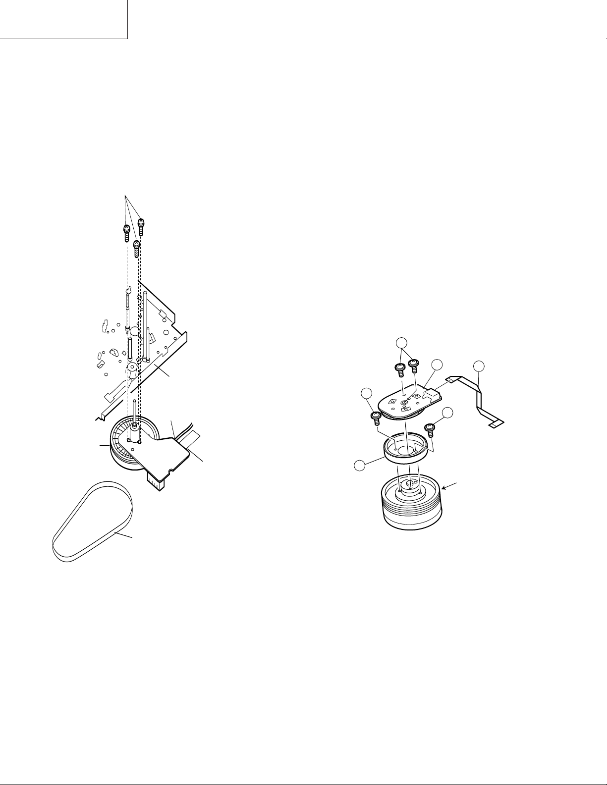
4-15 REPLACEMENT OF A/C (AUDIO/CONTROL)
HEAD
1. In eject position unplug the power cord.
• Removal
1. Take out FFC holder from main chassis.
(Push 3 hooking point and pull-up the
holder).
2. Remove the screws 123, Tilt screw.
3. Unsolder the PWB fitted to the A/C head.
Notes:
1. When replacing, never touch the head. If you touched,
clean with the cleaning liquid.
2. When removing the screw 3, take care so that the
spring may out.
3
A/C head screw
Azimuth spring
*Derection designation.
(The bottom part is big.)
2
Azimuth adj. screw
A/C head PWB ass’y
(with A/E)
Tilt screw
A/C head PWB
AC Head
FFC
Holder
3. Align the left end of gear of A/C head arm with the
punched mark of chassis, tentatively tighten the screws
1 so as to ensure smooth motion of A/C head arm.
Tightening torque must be 0.45 ± 0.05N·m (4.5 ±
0.5kgf·cm).
Height screw
1
Left end of A/C head arm gear
Punched line mark on chassis
Figure 4-23.
Note:
1. If the screw 1 is tighten tentatively too loose, the
azimuth and height of A/C head may change when they
are finally tightened. Therefore care must be taken.
2. After completion of A/C head be sure to adjust tape
running. (Execute the running adjustment by the method
described in 4-17.)
Height adj. screw
1
A/C head plate
Height Adj. spring
Figure 4-21.
• Replacement
1. Solder the removed PWB to the new head assembly.
2. Adjust the height from the A/C head arm (lower surface)
to the A/C head plate to 10.8mm with slide calipers. (3
places of azimuth screw section, tilt screw section and A/
C head front section) (See the figure below.)
New A/C head ass’y
A/C head PWB
Solder
A/C head plate
*Fit the groove of FFC to
the boss of the holder.
A/C head FFC
A/C FFC holder
10.8mm
Figure 4-22.
18
4-16 A/C HEAD HEIGHT ROUGH ADJUSTMENT
• Setting
Azimuth screw
TiH screw
Height screw
VC-A10/A10S/A500
VC-A50/A50S/A50SB
VC-A60/A75/A80S
4-17 ADJUSTMENT OF TAPE DRIVE TRAIN
1. Tape run rough adjustment
1 Check and adjust the position of the tension pole.
(See 4-12.)
2 Check and adjust the video search rewind back
tension. (See 4-10.)
3 Connect the oscilloscope to the test point for PB ATR
signal output (TP201). Set the synchronism of the
oscilloscope to EXT. The PB ATR signal is to be
triggered by the head switching pulse (TP202).
4 Set the alignment tape (VROCPSV) to play.
Guide roller
Cassette tape
500g
Mechanism chassis
Weight to prevent
float (500g)
Figure 4-24.
1. Set the cassette tape in the unit.
2. Press the PLAY button to put the unit in the playback
mode.
3. Roughly adjust the height of the A/C head by turning the
height screw until the tape is in the position shown
below.
A/C head
Tape
0.3mm
Figure 4-25.
• Adjustment
Adjust the height screw visually so that the control head is
visible 0.3mm below the bottom of the tape.
Cassette Tape
Figure 4-26.
5 Press the tracking button (+), (–) and change the
ATR signal waveform from max to min and from min
to max. At this time make sure that the ATR signal
waveform changes nearly parallel.
6 Unless the ATR signal waveform changes nearly
parallel, adjust the height of supply side and take-up
side guide roller so that the envelope waveform
changes nearly parallel. (For ATR signal adjustment
procedure refer to Figure 4-30.)
7 Turn the tilt screw to remove the tape crease at the
fixing guide flange.
Playback the tape and check for tape crease at the
fixing guide flange.
(1)If there is no tape crease
Turn the tilt screw clockwise so that tape crease
appears once at the flange, and then return the tilt
screw so that the crease disappears.
(2)If there is tape crease
Turn counterclockwise the tilt screw so that the
tape crease disappears.
(Reference) If the tilt screw is turned clockwise
crease appears at the lower flange.
19
VC-A10/A10S/A500
VC-A50/A50S/A50SB
VC-A60/A75/A80S
Notes:
1. Previously set the tracking control in the center position,
and adjust the ATR signal waveform to maximum with X
value adjustment nut. Thereby the tape run rough adjustment is facilitated.
2. Especially the outlet side ATR signal waveform must
have higher flatness.
Figure 4-27.
2. Adjustment of A/C head height and azimuth
1 Perform the initial setting of A/C head position by the
method stated in «4-15 Replacement 3″.
2 Connect the oscilloscope to the audio output termi-
nal.
3 Using the alignment tape in which 1 kHz linear audio
signal has been recorded, adjust the height screw so
as to get max audio output.
4 Using the alignment tape in which 7 kHz linear audio
signal has been recorded, adjust the azimuth screw
so as to get max audio output.
5 The adjustment of 3 and 4 twice or three times
repeat, and finally adjust 4.
For X value adjustment
Adjust the X value, turning the geartype screwdriver.
Figure 4-28.
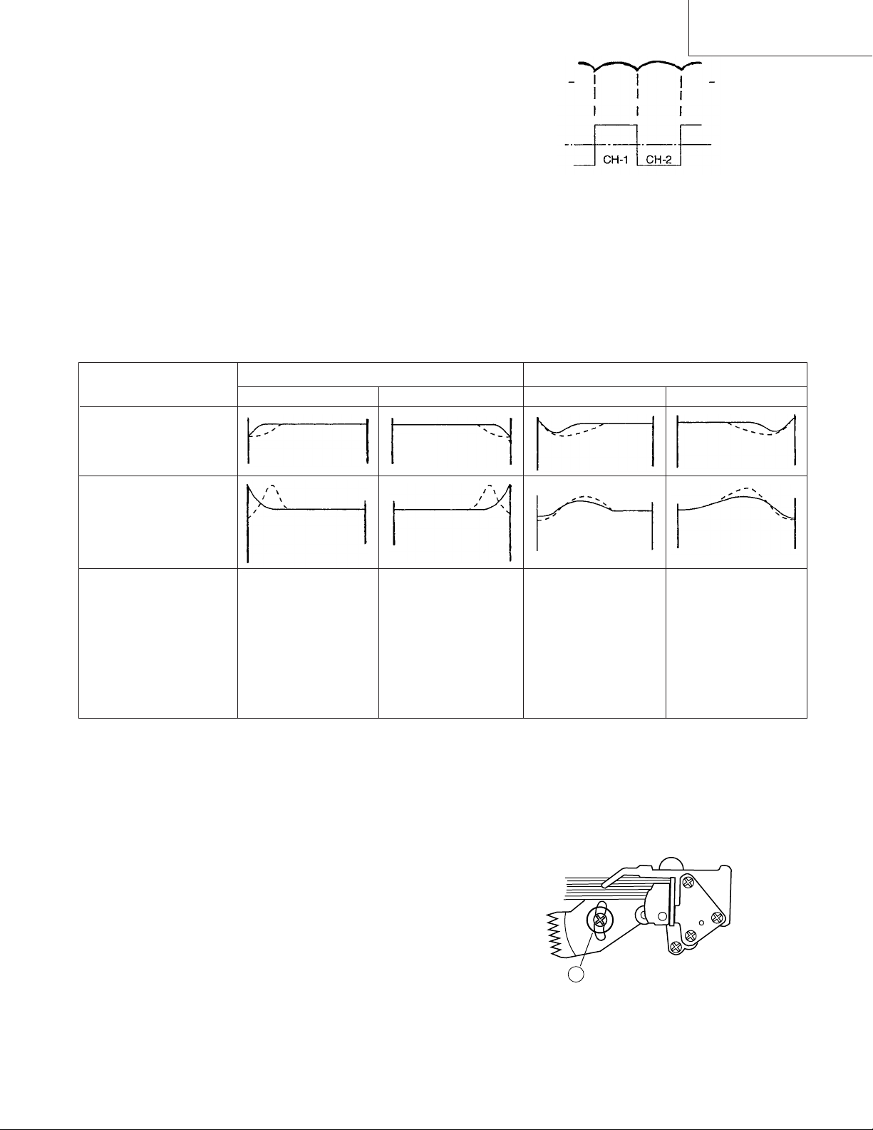
3. Tape run adjustment
1 Connect the oscilloscope to PB ATR signal output
test point, set oscilloscope sync to EXT, trigger-input
the PB CHROMA signal (head switching pulse).
2 Rough adjustment of X value
Tentatively fix A/C head arm screws 1 by the method
described in 4-15 «Replacement 3».
Playback the alignment tape (VROCPSV) and
shortcircuit between TP801 and TP802. As a result
the auto-tracking is automatically cancelled, so that
the X value adjustment mode is set.
Move the A/C head with the X value adjustment gear
driver (JiGDRiVER-6) by the method shown in Figure 4-33, and adjust the A/C head so as to get the
maximum ATR signal waveform. (Note: When the A/
C head is adjusted, adjust so that the maximum ATR
signal waveform is obtained nearest the position of
initial setting made in 4-15.)
20
3 Next, press the tracking button (+), (–) and change
the ATR signal waveform from max to min and from
min to max. At this time adjust the height of supply
and take-up side guide roller with the adjustment
driver (JiGDRiVERH-4) so that the ATR signal waveform changes nearly parallel.
4 If the tape is lifted or sunk from the helical lead
surface, the PB ATR signal waveform appears as
shown in Figure 4-30.
5 Press the tracking button (+), (–) and make sure that
the ATR signal waveform changes nearly parallel.
6 Finally, check tape crease near the reverse guide. If
tape crease is found, adjust tilt screw 45˚ counter
clockwise. Small tape crcase will appear at retain
guide after this adjustment finished.
Supply side
Take-up side Supply side Take-up side
VC-A10/A10S/A500
VC-A50/A50S/A50SB
VC-A60/A75/A80S
PB ATR
Signal
Head switching pulse
Figure 4-29.
4. A/C head X value adjustment
1 Fix A/C head arm screws 1 by the method described
in 4-15 «Replacement 3».
2 Playback the alignment tape (VROCPSV), and
shortcircuit between TP801 and TP802. As a result
the auto-tracking is automatically cancelled, so that
the X value adjustment mode is set.
When the tape is below the helical lead.When the tape is above the helical lead.
Adjustment
Supply side guide roller
rotated in clockwise
direction (lowers guide
roller) to flatten
ATR signal.
Take-up side guide roller
rotated in clockwise
direction (lowers guide
roller) to flatten
ATR signal.
Figure 4-30.
3 Move the A/C head with the X value adjustment gear
driver by the method shown in Figure 4-33, and
adjust the A/C head so as to get the maximum ATR
signal waveform. (Note: At this time adjust so as to
get the maximum ATR signal waveform nearest the
A/C head position which has been set in case of X
value rough adjustment as stated in 4-17, 3- 2.)
4 Adjust the playback switching point (Refer to the
electric adjustment method.)
5 Playback the self-picture-recorded tape, and check
the flatness of ATR signal waveform and sound.
Supply side guide roller
rotated in counterclockwise direction (raises
guide roller) to make the
tape float above the helical
lead. The supply
side guide roller is then
rotated in the clockwise
direction to flatten the
ATR signal.
Take-up side guide roller
rotated in counterclockwise direction (raises
guide roller) to make the
tape float above the
helical lead. The take-up
side guide roller is then
rotated in the clockwise
direction to flatten the
ATR signal.
Notes:
When the A/C head X value adjustment is performed, be
sure to perform at first X value rough adjustment (refer to 4-
17, 3-2).
1
21
Figure 4-31.
VC-A10/A10S/A500
VC-A50/A50S/A50SB
VC-A60/A75/A80S
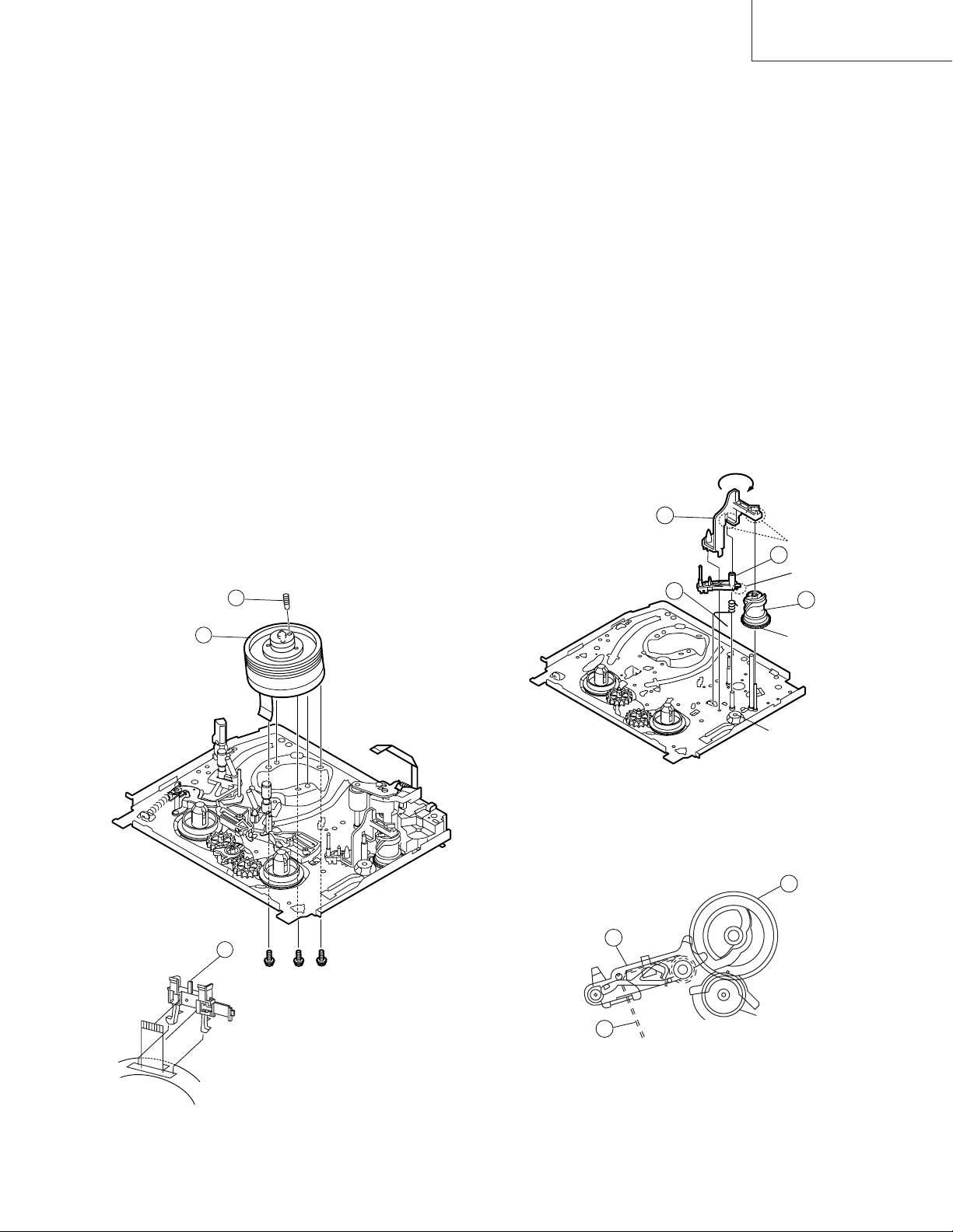
4-18 REPLACEMENT OF THE CAPSTAN D.D.
(DIRECT DRIVE) MOTOR
• Remove the mechanism from the set.
4-19 REPLACEMENT OF DRUM D.D. MOTOR
1. Set the ejection mode.
2. Withdraw the main power plug from the socket.
• Removal (Follow the order of indicated numbers.)
1. Unsolder loading motor wire and drum FFC (except for
VC-A50S).
2. Remove the reel belt 1.
3. Remove the three screws 2.
• Reassembly
2
Mainchassis
• Removal (Perform in numerical order.)
1. Disconnect the FFC cable 1.
2. Unscrew the D.D. stator assembly fixing screws 2.
3. Take out the D.D. stator assembly 3.
4. Unscrew the D.D. rotor assembly fixing screws 4.
5. Take out the D.D. rotor assembly 5.
Notes:
1. In removing the D.D. stator assembly, part of the drum
earth spring pops out of the pre-load collar.
Be careful not to lose it.
2. Install, so that the D.D. rotor ass’y and upper drum ass’y
mounting direction check holes align.
(Align the upper drum dent with the rotor hole.)
3. Be careful not to damage the upper drum or the video
head.
4. Protect the hole elements from shock due to contact with
D.D. stator or D.D. rotor ass’y.
5. After installation adjust the playback switching point for
adjustment of servo circuit.
2
D.D.stator ass’y
2
4
1
Solder loading motor wire
Capstan
D.D. motor
Solder drum FFC
1
Reel belt
Figure 4-32.
1. Taking care so that the capstan shaft does not contact
the mechanism chassis, set its position on the mechanism chassis, and then install with the three screws.
2. Install the reel belt.
3. Solder loading motor wire and insert drum FFC (except
for VC-A50S).
Notes:
1. After installing the capstan D.D. motor, be sure to rotate
the capstan D.D. motor and check the movement.
2. Set the tape, and check for the tape crease near the
reverse guide in the playback mode. Adjust the A/C
head and azimuth as stated in 4-17 item 2.
4
5
Figure 4-33.
D.D. rotor ass’y
Upper drum
FFC
22
4-20 REPLACING THE UPPER AND LOWER
DRUM ASSEMBLY
• Replacement (Perform in the numerical order)
1 Remove the motor as stated in 4-19 D.D. motor replace-
ment.
2 Remove the drum earth brush ass’y 2.
3 Remove the upper and lower drum assembly from main
chassis 1.
4 Remove the drum FFC holder 3.
VC-A10/A10S/A500
VC-A50/A50S/A50SB
VC-A60/A75/A80S
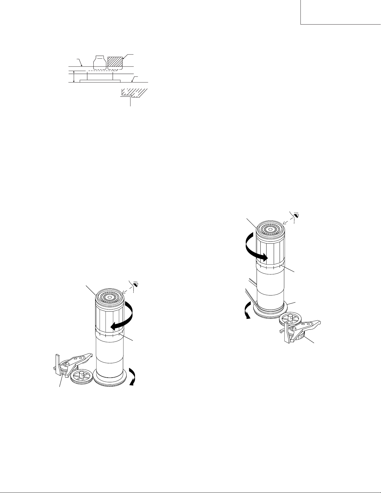
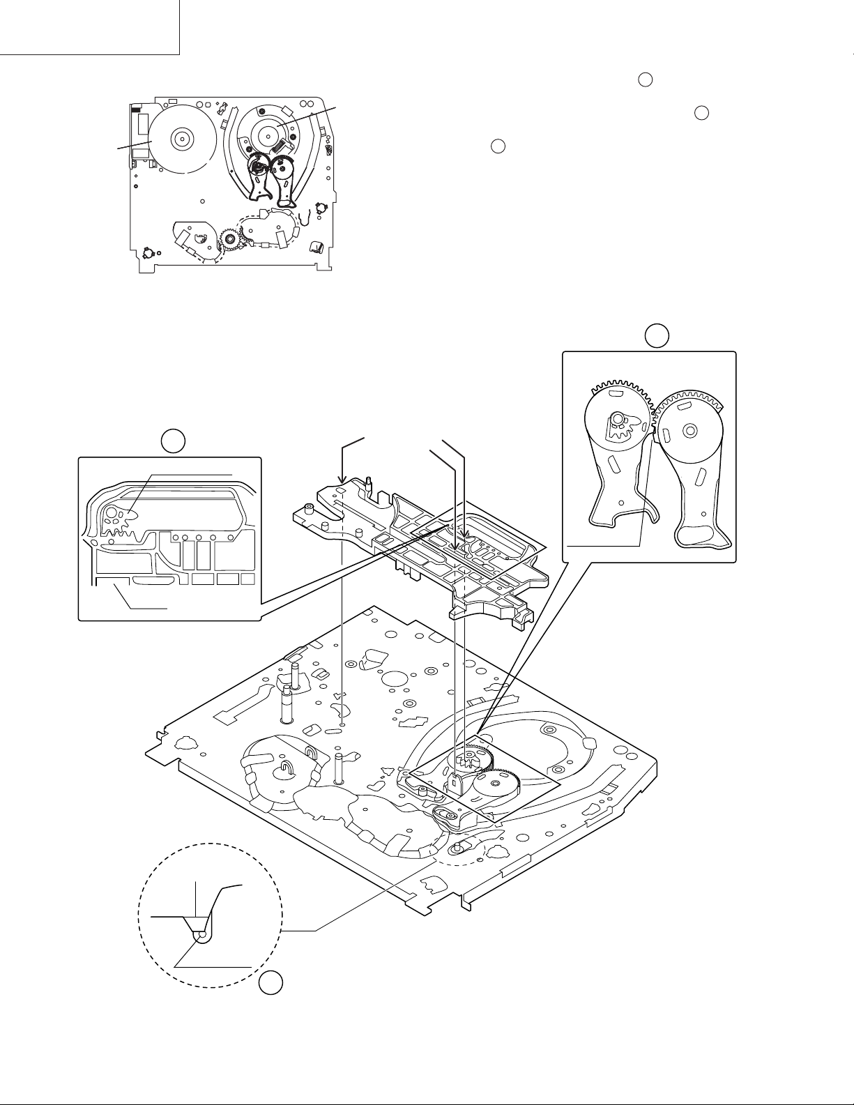
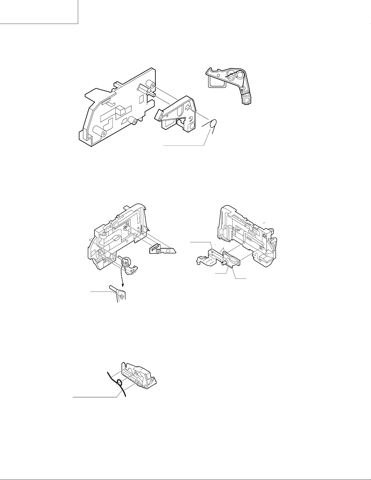
4-21 ASSEMBLING OF PHASE MATCHING
MECHANISM COMPONENTS
• Assemble the phase matching mechanism components in the following order.
1. Assemble the reverse guide lever and pinch drive cam.
2. Mounting the shifter (on the back of the mechanism
chassis).
3. Mounting the master cam (on the back of the mechanism chassis).
4. Assemble synchro gear.
5. Assemble the loading motor parts.
[Cares when replacing the drum]
1. Be careful so that the drum earth brush is not lost.
2. Do not touch directly the drum surface.
3. Fit gently the screwdriver to the screws.
4. Since the drum assembly is an extremely precise assembly, it must be handled with utmost care.
5. Make sure that the drum surface is free from dust, dirt
and foreign substances.
6. After replacing the drum be sure to perform the tape
running adjustment.
After that, perform also the electrical adjustment.
• Playback switching point adjustment
• X-position adjustment and check
• Standard and x-3 slow tracking adjustment
7. After replacing the drum clean the drum.
2
1
• PINCH DRIVE CAM AND REVERSE GUIDE
LEVER ASSEMBLING METHOD.
(Place the following parts in position in numerical order.)
(1)Pinch drive cam 1
(2)Reverse guide spring 2
(3)Reverse guide lever ass’y 3
(4)Open guide 4
4
2
Insert it into the
groove of the shaft
3
Don’t run up
on the spring
1
Dot A
Dot B
Lower drum bottom side
3
Figure 4-34.
Figure 4-35.
1
3
Synchro gear
2
From Top View
23
VC-A10/A10S/A500
VC-A50/A50S/A50SB
VC-A60/A75/A80S
4-22 INSTALLING THE SHIFTER
Capstan D.D.
motor
(Bottom side of mechanism chassis)
Drum
1. Make sure that the loading arm T and S are at the PhaseMatching point as shown below .
a
2. Fix the shifter position setting part to the roading arm T
position setting part as shown in figure .
b
3. Make sure tension arm not run on the shifter as shown
in figure .
c
Figure 4-36.
b
Loading arm (T)
Shifter
Insert point
Loading arm (T)
Phase matting
a
Loading arm (S)
*Not run on the
sifter.
Sifter
Tension arm
c
Figure 4-37.
24
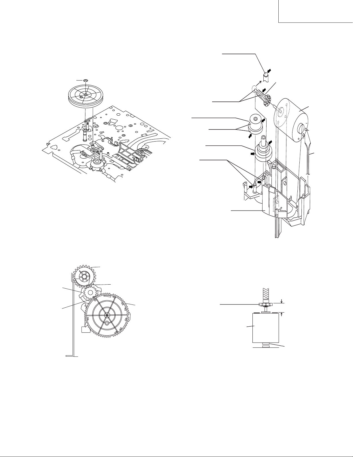
4-23 INSTALLING THE MASTER CAM (AT
REAR SIDE OF MECHANISM CHASSIS)
1. Make sure beforehand that the shifter is at initial position. (Right side from bottom view)
2. Place the master cam in the position as shown below.
3. Fix the E ring.
VC-A10/A10S/A500
VC-A50/A50S/A50SB
VC-A60/A75/A80S
4-24 REPLACEMENT OF LOADING MOTOR
• Removal
Apply grease
*Apply grease to
the tip as well.
E-ring
Figure 4-38-1.
4. Adjust the master cam and pinch drive cam, fix the
synchro gear in correct position.
Note:
See the figure below for the phase matching between the
master cam synchro gear and pinch drive cam.
Apply grease
Leading connect gear.
Apply grease
Worm wheel gear.
Apply grease
L-M-Block.
Figure 4-39.
Worm gear
Red
Loading
motor.
Wire
+ : Red
— : White
Insert
Synchro
gear
Phase
matching
Pinch Drive Cam
Hole of Pinch Drive Cam
Figure 4-38-2.
Master Cam
• Replacement
Remove the loading motor, and install the replacement
loading motor as shown below.
Worm gear
Loading
motor
To press the motor in, first
receive it by portion A.
+0
6.95 mm
-0.15
A part
Figure 4-40.
The loading motor pressing-in must be less than 196N (20
kgf).
Adjust the distance between motor and pulley to 6.95
+0. 2
mm.
–0.15
25
VC-A10/A10S/A500
VC-A50/A50S/A50SB
VC-A60/A75/A80S
4-25 ASSEMBLY OF CASSETTE HOUSING
1. Proof lever Proof lever spring and Holder R
*Proof lever spring fixing direction designated.
2. 0pen lever, Sensor Plate and Frame R
MSPRD0215AJFJ
Figure 4-41.
Take care that
not to damage
this parts.
3. Spring to Drive Arm R
MSPRD0212AJFJ
out side
top
out side
inside
bottom
Figure 4-42.
Figure 4-43.
26
Loading…
View the manual for the Sharp VC-A50 here, for free. This user manual comes under the category video cassette recorders and has been rated by 3 people with an average of a 8.1. This manual is available in the following languages: -. Do you have a question about the Sharp VC-A50?
Ask your question here
Frequently asked questions
Can’t find the answer to your question in the manual? You may find the answer to your question in the FAQs about the Sharp VC-A50 below.
Is the manual of the Sharp VC-A50 available in English?
Unfortunately, we do not have the manual for the Sharp VC-A50 available in English. This manual is available in -.
Is your question not listed? Ask your question here
Sharp Service Manual
S62L3VC-A10
VC-A10/A10S
VC-A50/A50S/A50S(B)
VC-A500
VC-A60
VC-A75
VC-A80S
- Addeddate
- 2021-10-27 18:01:55
- Identifier
- sharp-service-manual-vc-a10a10s-vc-a50a50sa50sb-vc-a500-vc-a60-vc-a75-vc-a80s
- Identifier-ark
- ark:/13960/t7xn12630
- Ocr
- tesseract 5.0.0-beta-20210815
- Ocr_detected_lang
- en
- Ocr_detected_lang_conf
- 1.0000
- Ocr_detected_script
- Latin
- Ocr_detected_script_conf
- 0.9114
- Ocr_module_version
- 0.0.13
- Ocr_parameters
- -l eng
- Page_number_confidence
- 98.80
- Ppi
- 300
comment
Reviews
There are no reviews yet. Be the first one to
write a review.
140
Views
DOWNLOAD OPTIONS
Temporarily Unavailable
DAISY
For users with print-disabilities
Temporarily Unavailable
EPUB
Uploaded by
FakeShemp
on
1
VC-A10/A10S/A500
VC-A50/A50S/A50SB
VC-A60/A75/A80S
VIDEO CASSETTE PLAYER
VC-A10/A10S/A50/A50S/
A50S(B)/A60/A75/A80S
VC-A500
SERVICE MANUAL
CONTENTS
Page
1. SPECIFICATIONS………………………………………………………………………………………………….. 2
2. DISASSEMBLY AND REASSEMBLY ……………………………………………………………………….. 3
3. FUNCTION OF MAJOR MECHANICAL PARTS …………………………………………………………. 6
4. ADJUSTMENT, REPLACEMENT AND ASSEMBLY OF MECHANICAL UNITS ……………… 9
5. ELECTRICAL ADJUSTMENT ………………………………………………………………………………… 28
6. MECHANISM OPERATION FLOWCHART AND TROUBLESHOOTING GUIDE…………… 31
7. TROUBLESHOOTING ………………………………………………………………………………………….. 37
8. BLOCK DIAGRAM………………………………………………………………………………………………… 45
9. SCHEMATIC DIAGRAM AND PWB FOIL PATTERN ………………………………………………… 55
10. REPLACEMENT PARTS LIST ……………………………………………………………………………….. 68
11. EXPLODED VIEW OF MECHANICAL PARTS …………………………………………………………. 77
12. PACKING OF THE SET ………………………………………………………………………………………… 82
SHARP CORPORATION
MODELS
In the interests of user-safety (Required by safety regulations in some countries) the
set should be restored to its original condition and only parts identical to those
specified be used.
VC-A10/A10S
VC-A50/A50S/A50S(B)
VC-A500
VC-A60
VC-A75
VC-A80S
S62L3VC-A10//
-
Repair manuals
1
Sharp VC-A50/A50S/A50S(B) service manual
(84 pages)
- Languages:English
-
Type:
PDF -
Size:
11.35 MB
Preview
Sharp VC-A50/A50S/A50S(B) (Video Recorders (VHS, VCR)) service manuals in PDF format will help to find failures and errors and repair Sharp VC-A50/A50S/A50S(B) and restore the device’s functionality.