
•
Latched •
Latching •
Momentary •
RF •
RX480E •
Toggle •
User manual
Operating Introduction
Clearing the code :
Push the learning button on the receivers for 8 times , the codes will be cleaned .
After clearning the code, all the remote control cannot work any more.
Learning the code :(momentary)
Push the learning key on the receiver once time , it comes into momentary setting mode .
Wait for a moment , the LED will be off , it comes into learning state .
Push the remote button , LED indicator on the receiver board will flash then come off .
After 3 seconds, the LED indicator will be on again , learning successfully .
Learning the code : ( Toggle )
Push the learning key on the receiver twice time , it comes into toggle setting mode
Wait for a moment , the LED will be off , it comes into learning state .
Push the remote button,LED indicator on the receiver board will flash then come off.
After 3 seconds , the LED indicator will be on again , learning successfully .
Learning the code  Latching )
Note: When you choose for latching mode , in order to learn more remote control , you need to learn two different button , the first time learnt is for «ON», the second time learnt for «OFF».
For example : button A = ON , button B = OFF
Push the learning key on the receiver triple time , it comes into latching mode .
Wait for a moment , the LED indicator on the receiver board will flash then come off.
Push the remote button A .
LED flash for 5 times .
Push the remote button B .
Led flash for 5 times .
After 3 seconds , the LED indicator will be on again , learning successfully.
A = ON , B = OFF .
Applications
1.wireless power switch, socket, remote control switch, receiver module,
2. access control, electric cars, motorcycles, automobile anti-theft products, remote door openers, closers control system
3. security, surveillance systems, home security products, electric doors, alarm host, alarm
4. rooms controls, shutter doors, windows, remote control socket, remote control LED, remote audio remote control electric doors, garage door remote control, remote control retractable doors, remote rolling gates, sliding door
5. smart home products, remote control curtains, remote MP3, audio
Specifications
Model Number:RX480E-4
Working Temperature : -25~75C
Receive Sensitivity: -108dB
Quiescent Current : <=5mA
Working Voltage : DC3.3~5V
Working Frequency: 433.92MHz
Support encoding chip model: EV1527, PT2262
(Others can be customized,but at least 1000pcs)
Function
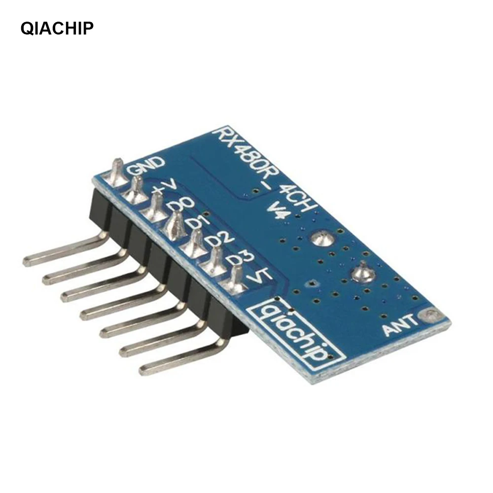
Pin-out instructions:
GND : groud or negative pole
+V : DC3.3~5V input
D0: Data output
D1: Data output
D2: Data output
D3: Data output
VT: Output
Working mode:Point move, self-locking, interlocking
The output: 4 channel CMOS level signal Corresponding to the remote control ABCD 4 buttons.

Introduction of working mode:
1. Press the learning button on the module 1 time. After the remote controller learns, it enters the jog mode;
2. Press the learning button on the module twice, and the remote controller will enter the self-locking mode after learning;
3. Press the learning button on the module 3 times, and the remote controller will enter the interlock mode after learning;
4. Press the learning button on the module 4 times. After the remote control learns,
Enter two-way self-locking + two-way jog mode;
5. Press the learning button on the module 5 times. After the remote control learns,
Enter two-way jog + two-way interlock mode;
6. Press the learning button on the module 6 times. After the remote control learns,
Enter two-way self-locking + two-way interlocking mode;
7. Press the learning button on the module 7 times. After the remote control learns,
Enter two-way interlock + two-way interlock mode;
Explanation of the purpose of this LED output signal:
When any button of the remote control is pressed, the receiving end decodes and decodes correctly, the LED will output a high-level signal 1. When the remote control button is released, the LED output will become 0.
That is: it will be output only when the reception is valid and decoded correctly.
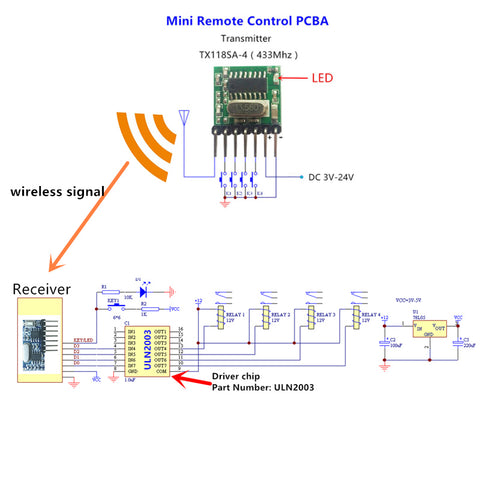
Wiring schematic diagram of RX480E and TX118SA
Shop now
← Older Post
Newer Post →
ManualsPro
QIACHIP
QIACHIP KR1204 433Mhz Wireless Remote Control Switch DC 12V 4 CH Relay Receiver Instruction Manual
- June 14, 2024
- QIACHIP
Table of Contents
- KR1204 433Mhz Wireless Remote Control Switch DC 12V 4 CH Relay Receiver
- DC lamp wiring diagram
- External power control lamp wiring diagram
- Wiring diagram of two DC motors
- How to set the working mode of the switch controller?
- Documents / Resources
- References
- Read User Manual Online (PDF format)
- Download This Manual (PDF format)
12V 4CHANNEL RECEIVER
INSTRUCTION
KR1204 433Mhz Wireless Remote Control Switch DC 12V 4 CH Relay Receiver

| Light
—|—
+/+V| Power positive
-/GND| Power negative
NC/Normally closed| 1 4 7 1 0
NO/Normally open| 3 6 9 12
COM/Public port| 2 5 8 11
DC lamp wiring diagram

*Please Don’t install with electricity
External power control lamp wiring diagram
External power supply can be connected to any voltage

*Please Don’t install with electricity
Wiring diagram of two DC motors

*Please Don’t install with electricity
- Note: All the following working modes need to be implemented with QIACHIP brand remote control (transmitter) and controller (receiver / wireless remote control switch). There is no guarantee that remote controls from other brands will work properly.
Reset function:
Clear all matched remotes. When the data is cleared, all remote control can’t
make receiver work.
Settings reset:
After pressing the receiver’s learning button 8 times, the receiver clears all
remote control data in its memory. When the receiver’s LED flashes, the reset
function is complete.
Description of the three working modes :
Working modes: 1) Momentary; 2) Toggle; 3) Latching.
-
Momentary mode:
After successful pairing in this mode, press and hold the remote control
button (such as A), the corresponding relay on the receiver is turned on;
release the remote control button (such as A), and the corresponding relay on
the receiver is turned off; -
Toggle mode:
After successful pairing in this mode, press the remote control button (such
as A) to turn on the corresponding relay on the receiver; press the remote
control button (such as A) again to turn off the corresponding relay on the
receiver; -
Latching mode:
After successful pairing in this mode, press the remote control button (such
as A), the receiver relay corresponding to A is turned on; press the remote
control button (such as B), the relay on the receiver corresponding to A is
turned off, and the receiver corresponding to B is turned on the relay is
open. And so on, press the remote control A and B at the same time, the
receiver will turn off.
How to set the working mode of the switch controller?
Note: All working modes require the same QIACHIP remote control
(transmitter) for implementation, and there is no guarantee that other brands
can also work properly in pairing.
Note: The working mode can only be set when the LED indicators of the
switch controller are lit.
Set Momentary mode (Jog):
Step 1) Press the receiver’s learning button once. Wait for the LED on
the receiver to light up and enter the setting state.
Step 2) Press the button on the remote control (eg button A) once. The
LED on the receiver will flash and then turn off. The jog mode is set
successfully.
Set Toggle Mode:
Step 1) Press the learning button on the receiver twice.
Wait for the LED on the receiver to light up and enter the setting state.
Step 2) Press the button on the remote control (eg button A) once. The
LED indicator on the receiver will flash and then turn off. The self-locking
mode is set successfully.
Set Latching Mode:
Step 1) Press the learning button on the receiver 3 times.
Wait for the LED on the receiver to light up and enter the setting state.
Step 2) Press the button on the remote control (such as button A) once.
The LED on the receiver will flash and then turn off, and the interlock mode
is set successfully.
*The following modes require a four-button remote control:
2CH Momentary + 2CH Toggle: Press the learning key on the receiver board
4 times ( LED Indicator on receiver board will flash simultaneously), then
press any key on the remote control, LED indicator on the receive flashes 3
times indicates pair successfully.
2CH Momentary + 2CH Latched: Press the learning key on the receiver board
5 times (LED Indicator on receiver board will flash simultaneously), then
press any key on the remote control, LED indicator on the receive flashes 3
times indicates pair successfully.
2CH Toggle + 2CH Latched: Press the learning key on the receiver board 6
times (LED Indicator on receiver board will flash simultaneously), then press
any key on the remote control, LED indicator on the receive flashes 3 times
indicates pair successfully.
2CH Latching + 2CH Latched: Press the learning key on the receiver board
7 times (LED Indicator on receiver board will flash simultaneously), then
press any key on the remote control, LED indicator on the receive flashes 3
times indicates pair successfully.
| Input Power | DC12V |
|---|---|
| RF Frequency | 315MHZ/433.92MHZ |
| Standby Current | 5mA |
| Match Way | Learning button |
| Receiver sensitivity | -104dbm |
| Operation mode | Momentary,Mode,Toggle,Mode,Latching mode |
| Output | NO , NC , COM,+V,GND |
| Support Encoding Chip | Learning Code 1527 |
| Working temperature | -10 ~ +80°C |
| Size | 68.2×48.2(mm) |
For more services, please check our website.
www.qiachip.com
Documents / Resources
|
QIACHIP KR1204 433Mhz Wireless Remote Control Switch DC 12V 4 CH Relay
Receiver
[pdf] Instruction Manual
KR1204 433Mhz Wireless Remote Control Switch DC 12V 4 CH Relay Receiver,
KR1204, 433Mhz Wireless Remote Control Switch DC 12V 4 CH Relay Receiver,
433Mhz Wireless Remote Control Switch DC 12V 4 CH Relay Receiver, Wireless
Remote Control Switch DC 12V 4 CH Relay Receiver, Remote Control Switch DC 12V
4 CH Relay Receiver, Control Switch DC 12V 4 CH Relay Receiver, Switch DC 12V
4 CH Relay Receiver, DC 12V 4 CH Relay Receiver, 12V 4 CH Relay Receiver, 4 CH
Relay Receiver, Relay Receiver, Receiver
—|—
References
- QIACHIP Remote control switch 433.92 MHz RF transmitter receiver
Read User Manual Online (PDF format)
Read User Manual Online (PDF format) >>
Download This Manual (PDF format)
Download this manual >>
Характеристики
- Модель: Qiachip KR1201A/KT05
- Напряжение питания
- релейный блок: 10В ~ 14В DC постоянного тока
- пульт ДУ: 3В DC, элемент CR2016
- Потребление (релейный блок): 5 ~ 35мА
- Частота радиосигнала: 433.92МГц
- Модуляция: ASK
- Чувствительность супергетеродинового приёмника, мин.: 97дБм
- Дистанция РЧ-связи: 30 ~ 50 метров
- Совместимость: пульты ДУ с кодом обучения 1527
- Тип реле: электромеханическое
- Количество каналов: 1
- Режимов коммутации (программ): 7
- Нагрузка:
- постоянное напряжение: до 28 Вольт, ток 7 Ампер
- переменное напряжение: до 250 Вольт, ток 5 Ампер
- Подключение: винтовые клеммы-терминалы
- Пульт: 2-кнопочный (дизайн кнопок «A/B» или «ON/OFF»)
- Температура эксплуатации: -10°С ~ +80°С
- Размеры
- релейный блок: 42 х 40 х 26мм
- пульт ДУ: 62 х 30 х 12мм
Состав комплекта
- Релейный блок 433МГц KR1201-A — 1шт
- Пульт ДУ 433МГц KT05 — 1шт
- Инструкция пользователя (языки: кит., англ.) — 1шт
Беспроводное мультирежимное коммутационное реле с приёмопередатчиком, функционирующим на частоте радиоволны 433МГц, укомплектованное двухкнопочным пультом дистанционного управления. Область применения: бытовое оборудование, промышленное автоматическое оборудование, автомобилестроение, самодельные электронные механизмы.
Дистанция уверенной связи между пультом и релейным блоком колеблется в диапазоне 20-50 метров. На сокращение расстояния связи влияют различные присутствующие препятствия. Электроника в релейном блоке способна запоминать и работать с несколькими пультами одновременно, поддерживающими протокол энкодера EV1527. Встроенная программа с выбором режимов переключения состояний реле «активный/пассивный» (или «включено / выключено») позволяет в четырех вариантах коммутировать электрические цепи между источником питания соответствующих параметров и любым исполнительным оборудованием. Модуль 1-канального реле Qiachip KR1201A/KT05 легко настраивается и обучается.
Интерфейсы подключения релейного блока, ключевые компоненты
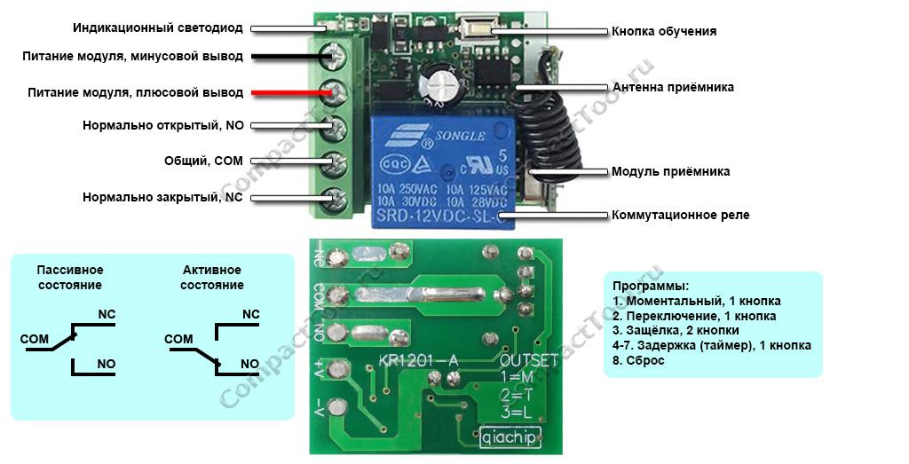
|
Обозначение и назначение входов реле
Установленное в релейном блоке электромеханическое реле подобно конструкции двухполюсного переключателя с одной общей линией, управляемое сигналами встроенного запрограммированного контроллера (ЦПУ). В исходном или пассивном состоянии, когда на реле не поступает сигнал включения или от схемы релейного блока отключено питающее напряжение, общая линия COM замкнута с нормально закрытым контактом (NC), нормально открытый контакт (NO) просто «висит» в воздухе, ни с чем не соединённый. Переключение реле из пассивного состояние в активное, вызванное сигналом со стороны ЦПУ в момент нажатия кнопки на пульте ДУ, реверсивно меняет соединение контактов NO и NC. В этом положении общая линия COM замкнута с нормально открытым контактом (NO), нормально закрытый контакт (NC) становится «подвешенным». Релейный канал имеет следующее обозначение входов, расположенных в однорядной линейке винтовых клемм подключения:
- NC — нормально закрытый контакт, замкнутый со входом COM в пассивном состоянии реле
- COM — общий контакт для входов NC и NO
- NO — нормально открытый контакт, «подвешенный в воздухе» в пассивном состоянии реле
Активное/пассивное состояние реле, выбор программы и распределение кнопок пульта ДУ
Выбор предустановленной в модуле программы переключения реле в активное/пассивное состояние осуществляется соответствующим количеством коротких и быстрых нажатий кнопки обучения на плате (1 раз — 1я программа, 2 раза — 2я программа, и т.д). За выбором программы следует обязательное назначение кнопок пульта ДУ соответствующим действиям реле, сопровождающееся 10-секундным свечением светодиодного индикатора. Успешное запоминание новой кнопки символизируется 3-кратным миганием индикатора. Сеанс настройки оканчивается выключением светодиода. В случае пропуска назначения кнопок пульта ДУ сохраняется режим работы ранее выбранной программы.
Модуль Qiachip KR1201A поддерживает работу с аналогичными многокнопочными пультами 433МГц, позволяет настраивать режимы переключения одноканального реле (программы):
- (1=М) Моментальный — нажатие и удержание кнопки на пульте переключает реле в состояние «активный», отпуск кнопки возвращает реле в исходное «пассивное» состояние;
- (2=T) Переключение — нажатие кнопки на пульте переключает реле в активное состояние, повторное нажатие той же кнопки возвращает реле в пассивное состояние;
- (3=L) Фиксированный (Защёлка) — нажатие первой кнопки (например, «А») на пульте ДУ переключает реле в активное состояние, нажатие второй кнопки (например, «В») возвращает реле в пассивное состояние;
- — 7. Задержка выключения (по таймеру) — нажатие кнопки на пульте ДУ переключает реле в активное состояние на 5/10/15/20 секунд, затем реле автоматически возвращается в пассивное состояние.
Сброс ранее выбранной программы производится 8-кратным нажатием кнопки обучения, подтверждаемый 3-разовым миганием светодиодного индикатора.
Радиоуправляемый модуль реле QA-R-011. Идеально подходит как для самостоятельного применения, так и в составе таких конструкторов как Arduino и Raspberry. Простое программирование. Поддерживает работу до 10 брелков.
Питание 3.6-24 VDC.
Потребление тока в режиме ожидания 3.6-5.5 мА.
Реле коммутирует 3.6-24 VDC, до 2А
Несущая частота 433 МГц (код 1527)
Размеры 22.5х11х8 мм.
3 режима работы:
1. Кнопка, momentary. Нажимаем кнопку на пульте — устройство включается и работает пока нажата кнопка. Отпускаем кнопку — устройство выключается.
2. Переключатель, toggle. Нажимаем кнопку на пульте — устройство включается. Нажимаем эту же кнопку повторно — устройство выключается.
3. Комбо, защелка, latched. Нажимаем кнопку А на пульте — устройство включается. Нажимаем кнопку B на пульте — устройство выключается.
Программирование:
Программирование производится при помощи обучающей кнопки на модуле.
Перед настройкой необходимо сделать сброс на заводские настройки (8 раз подряд нажмите кнопку обучения – реле ответит вспышками светодиода).
1. Режим «кнопка» Нажмите 1 раз на кнопку на плате приёмника. Дождитесь пока светодиод загорится постоянно. Затем нажмите на любую кнопку на пульте, после чего индикатор мигнет 3 раза и потухнет. Режим установлен. Теперь все кнопки на пульте будут работать в этом режиме.
2. Режим «переключатель» Нажмите 2 раза на кнопку на плате приёмника. Дождитесь пока светодиод загорится постоянно. Затем нажмите на любую кнопку на пульте, после чего индикатор мигнет 3 раза и потухнет. Режим установлен. Теперь все кнопки на пульте будут работать в этом режиме.
3. Режим «защелка» Нажмите 3 раза на обучающую кнопку. Светодиод загорится постоянным светом. Нажмите на пульте кнопку А, светодиод мигнет 3 раза в ответ. Затем нажмите кнопку B на пульте. Светодиод моргнет 3 раза и затем потухнет. Режим установлен. Алгоритм работы будет: A = ON, B = OFF.
В комплекте: модуль приемника с реле.
Подобрать пульт к этому модулю можно здесь
| Основные характеристики | |
| Особенности модуля | Реле беспроводное |
Задать вопрос о товаре
Написать отзыв
Can you envision effortlessly managing your devices from afar, eliminating the necessity for tangled wires or intricate configurations? With remarkable progress in wireless technology, the transformation of this vision into actuality is now feasible. This blog will explore the exhilarating domain of wireless control, employing the adaptable 433MHz RF module receiver. Let us begin without delaying it any further!
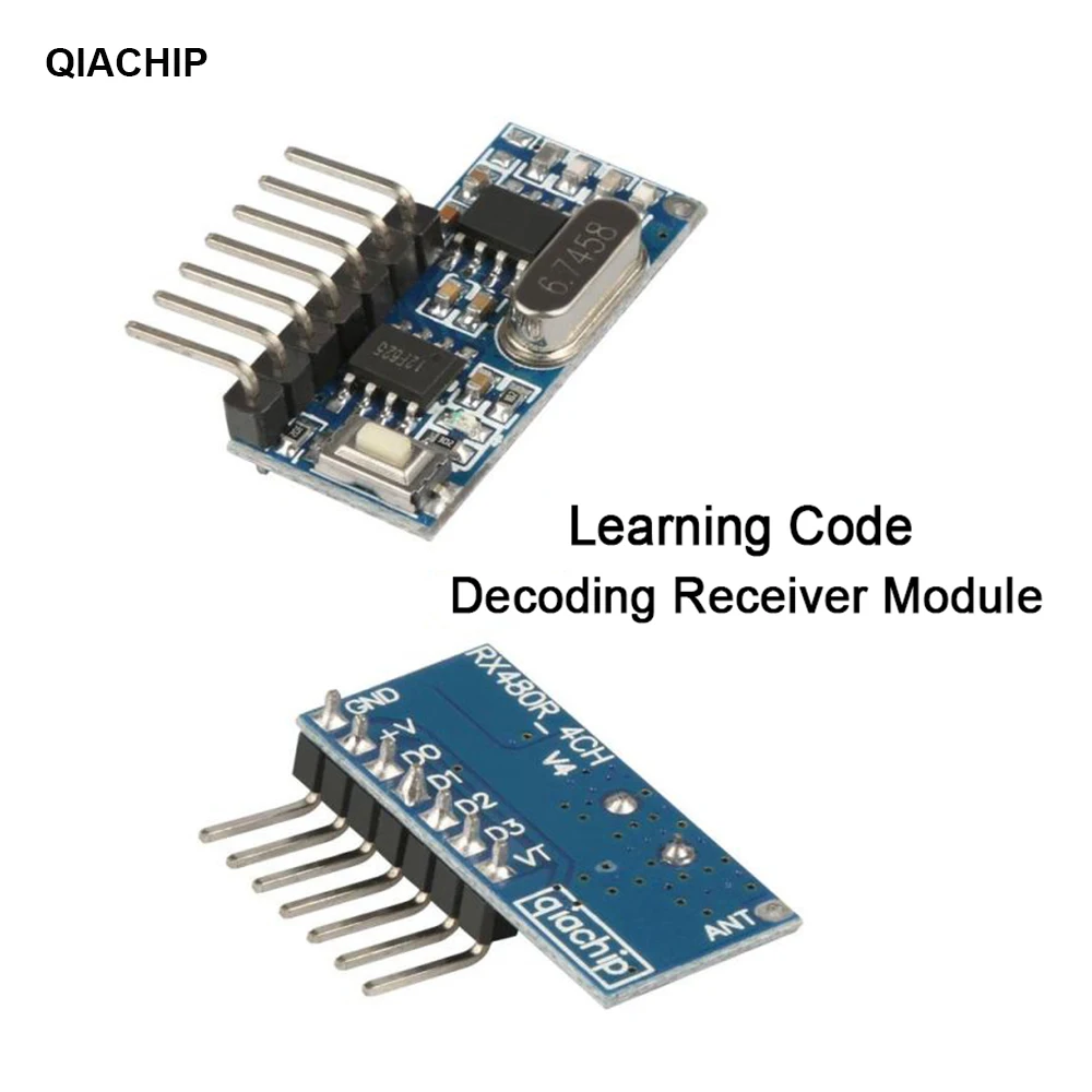
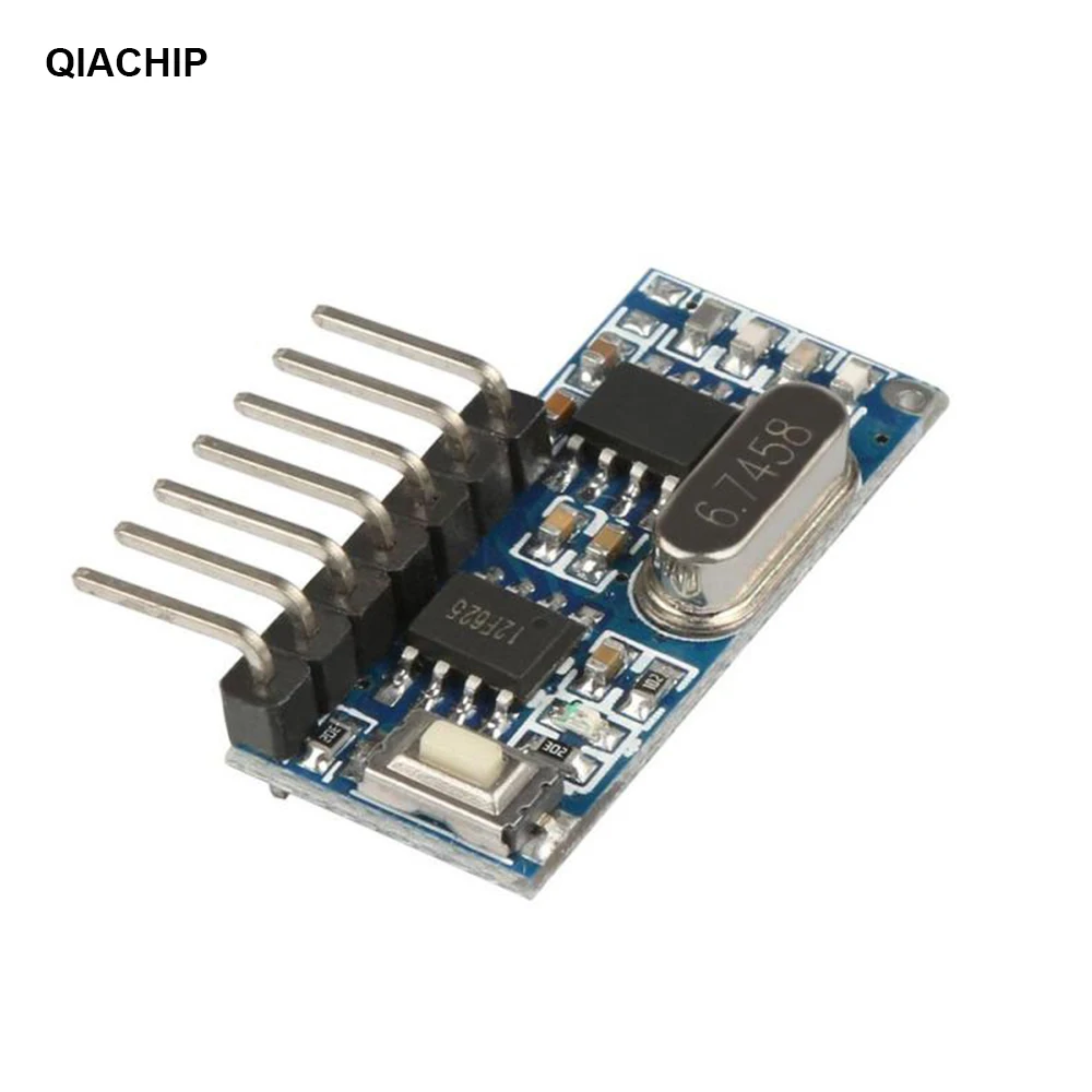
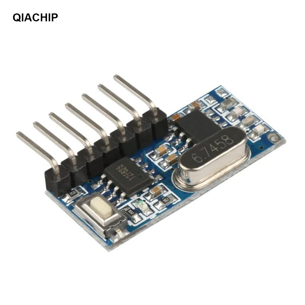
Understanding 433 MHz Receiver Module

First, let us see some specifications of the module:
- Working Voltage: DC3.3~5V
- Quiescent Current: ≤5mA
- Output current: 10 mA
- Working Frequency: 433MHz
- Receive Sensitivity: -108dB
- Receive Distance: 15 meters above
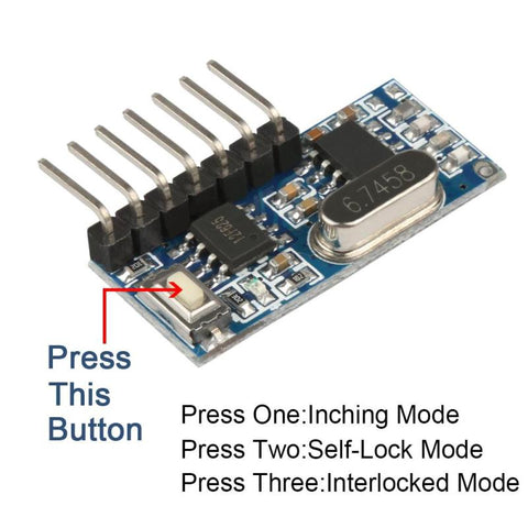
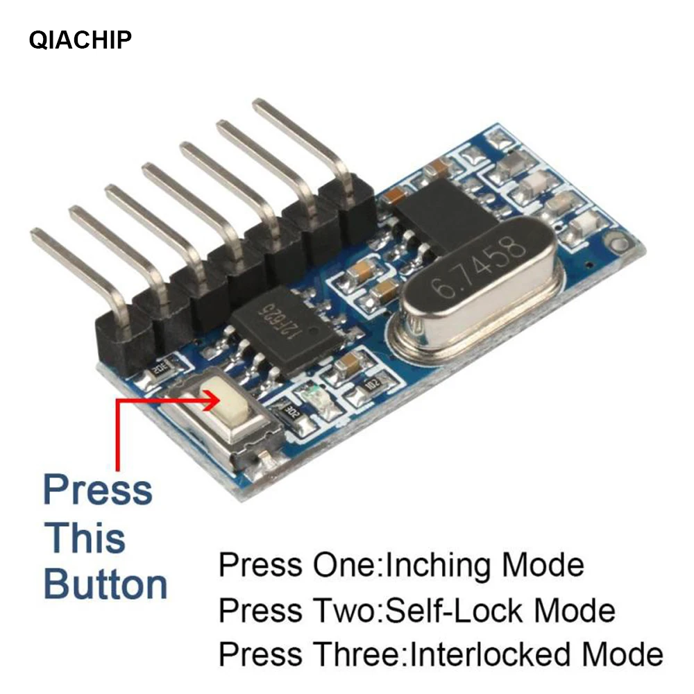
Learning Button:
A learning button is present on the receiver module. This button can be used to change between the different modes provided by the circuit. The functioning of the button is explained below:
|
No. of button presses |
Operating Mode |
|
1 |
Momentary Mode |
|
2 |
Latch Mode |
|
3 |
Interlock Mode |
|
8 |
Reset |
Working of the Receiver Module:
The 433MHz RF receiver module operates by picking up wireless signals at the 433MHz frequency using its antenna. These signals are then amplified to make them stronger, and demodulated to separate the original data from the modulated signals. The receiver decodes the data according to the specific protocol or encoding scheme employed. Subsequently, the decoded data becomes accessible to the connected device, allowing for actions or responses based on the received information. The receiver operates in three different modes that can be switched using the learning button. A more detailed explanation of each mode can be found in the subsequent sections.
The process of decoding and signal amplification is accomplished through the ICs installed on the module. The specific ICs utilized for these applications may vary for each module, as they depend on the manufacturer. In our case, a 12F625 IC is used for the decoding application. Let us see what it contributes to the circuit.
- 12F625 IC: The 12F625 microcontroller in a 433MHz receiver can carry out multiple functions, including decoding received signals, processing data, controlling output devices, implementing protocol-specific functions, and managing communication interfaces. Its role is crucial in ensuring the proper operation and functionality of the 433MHz receiver module.
The user can send the information by using an RF Remote. I have used a cloning remote here, you can use any other 4-channel remote as well. The working of the remote is explained in the next section.
433 MHz Cloning RF Remote
This device, which can replicate the codes of a 433 MHz RF remote control, is incredibly convenient. It has a range of approximately 100m and is powered by a 3V battery. The cloning remote possesses a learning mode that allows it to capture and save the codes transmitted by the original RF remote control.
I have used 4 keys of the remote to control the 4 LEDs connected to D0, D1, D2 and D3.
To learn more about the cloning remote, you can check out our blog on Cloning Remote which explains the cloning process in detail.
Components Required for Controlling LED with 433MHz RF Module
- 1 x QIACHIP Wireless 433MHz RF Module Receiver
- 1 x RF Remote Control
- 4 x LEDs
- Jumper Cables
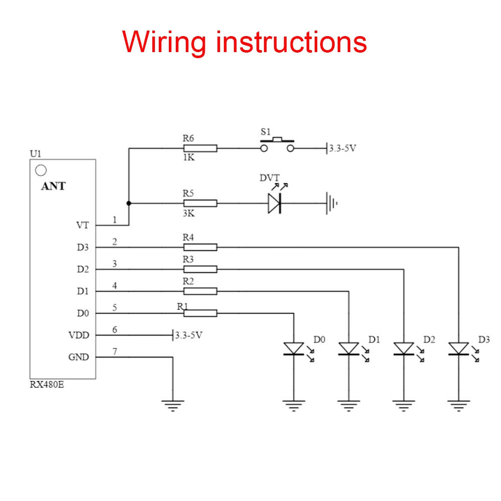
Circuit Diagram

Connections:
- Connect the +ve terminal of the battery to the V+ pin of the module.
- Connect the -ve terminal of the battery to the V- pin of the module.
- Connect the anode pins of the 4 LEDs to pins D0, D1, D2 and D3. You can also connect other devices like a buzzer or servo motor etc.
- Connect the cathode pins of the 4 LEDs to the -ve terminal of the battery.
Once you have made these connections, the overall circuit will look like this:

Demonstration of Controlling LEDs using RF Remote and Receiver:
The working of the overall circuit is quite simple. Once you are done connecting the LEDs to the digital pins (D0 – D3), supply power to the module by connecting it to the 3.7 V Li-ion Battery. As mentioned earlier, the module works in 3 modes, we shall go through them individually.
- Momentary Mode or Jog Mode: In the momentary mode, the 433MHz receiver module captures wireless signals, demodulates them, decodes the data, and activates an output device only when a button is pressed or an input signal is received.

The output is then deactivated once the button is released or the input signal ends. This mode allows for the temporary activation of devices without the requirement of continuous transmission or sustained output.
To activate the momentary mode, simply press the learning button on the module once. Upon doing so, the LED will flash once. At this point, you can register a button on the remote that you wish to use to control the connected LEDs. You can repeat this exact procedure for the remaining buttons.
- Toggle Mode or Self-Lock Mode: In the self-lock mode of a 433MHz receiver module, the output device stays active even after releasing the button or input signal. The module receives and decodes signals and activates the output according to the received data. To deactivate the output, a separate input signal or button press is usually required. This mode is commonly employed to keep the output device activated without the need for constant input.
To enter this mode, you need to press the learning button twice in a row. Once the LED starts glowing, you can register the button you want. After pressing a button, the LED will flash to indicate that the registration was successful.
- Interlock Mode: In the interlock mode of a 433MHz receiver module, various buttons or input signals independently control distinct outputs. Each button or signal is designated to a specific output, and when one is activated, the others are deactivated. This mode guarantees that only one output is operational at any given time, preventing conflicting actions. It is utilized in systems that necessitate sequential and exclusive command, such as motor control or security systems.
To activate this mode, press the learning button three times and register the desired keys in the same way as before.
Conclusion
Hope you liked the demonstration of the RF Receiver Module. The connections are quite easy to understand and the module itself is easy to interface. If you have any problems related to the project, you can drop your queries in the comments below.