

hp LaserJet 1000 series
service


hp LaserJet 1000 series printer
service

Copyright Information
© 2001 Hewlett-Packard
Company
All Rights Reserved.
Reproduction, adaptations, or
translation without prior written
permission is prohibited except
as allowed under copyright
laws.
Part number Q1342-90901
First edition, August 2001
Printed in USA
Warranty
The information contained in
this document is subject to
change without notice.
Hewlett-Packard makes no
warranty of any kind with
respect to thi s informatio n .
HEWLETT-PACKARD
SPECIFICALLY DISCLAIMS
THE IMPLIED WARRANTY OF
MERCHANTABILITY AND
FITNESS FOR A PARTICULAR
PURPOSE.
Hewlett-Packard shall not be
liable for any direct, indirect,
incidental, consequential, or
other damage alleged in
connection with the furnishing or
use of this information.
NOTICE TO U.S.
GOVERNMENT USERS:
RESTRICTED RIGHTS
COMMERCIAL COMPUTER
SOFTWARE: “Use, duplication,
or disclosure by the
Government is subject to
restrictions as set forth in
subparagraph (c) (1)(ii) of the
Rights in Technical Data Clause
at DFARS 52.227-7013.”
Trademark Credits
Microsoft, Windows, and MSDOS are U.S. registered
trademarks of Microsoft
Corporation.
TrueType is a U.S. trademark of
Apple Computer, Inc.
All other products mentioned
herein might be trademarks of
their respective companies.
Safety Information
WARNING!
Potentia l Shock Hazard
Always follow basic safety
precautions when using this
product to reduce risk of injury
from fire or electric shock.
1 Read and understand all
instructions in the user
guide.
2 Observe all warnings and
instructions marked on the
product.
3 Use only a grounded
electrical outlet when
connecting the
HP LaserJet 1000 printer
to a power source. If you
don’t know whether the
outlet is grounded, check
with a qualified electrician.
4 Do not touch the contacts
on the end of any of the
sockets on the
HP LaserJet 1000 printer.
Replace damaged cords
immediately.
5 Unplug this product from
wall outlets before
cleaning.
6 Do not install or use this
product near water or
when you are wet.
7 Install the product securely
on a stable surface.
8 Install the product in a
protected location where
no one can step on or trip
over the power cord and
the power cord will not be
damaged.
9 If the product does not
operate normally, see the
online user guide.
10 Refer all servicing
questions to qualified
personnel.
Information regarding FCC
Class B, Parts 15 and 68
requirements can be found in
the user guide.
Hewlett-Packard Company
11311 Chinden Boulevard
Boise, Idaho 83714 U.S.A.

Contents
Figures
Tables
1 Product information
Introduction . . . . . . . . . . . . . . . . . . . . . . . . . . . . . . . . . . . . . . . . . . .2
Printer features . . . . . . . . . . . . . . . . . . . . . . . . . . . . . . . . . . . . .2
Product specifications . . . . . . . . . . . . . . . . . . . . . . . . . . . . . . . . . . .3
Identification . . . . . . . . . . . . . . . . . . . . . . . . . . . . . . . . . . . . . . .3
Specification tables. . . . . . . . . . . . . . . . . . . . . . . . . . . . . . . . . .4
Overview of printer . . . . . . . . . . . . . . . . . . . . . . . . . . . . . . . . . . . . .6
Front and side view. . . . . . . . . . . . . . . . . . . . . . . . . . . . . . . . . .6
Back and side view . . . . . . . . . . . . . . . . . . . . . . . . . . . . . . . . . .7
Warranty statement. . . . . . . . . . . . . . . . . . . . . . . . . . . . . . . . . . . . .8
Extended warranty . . . . . . . . . . . . . . . . . . . . . . . . . . . . . . . . . .9
Toner cartridge information. . . . . . . . . . . . . . . . . . . . . . . . . . . . . .10
Refilled toner cartridges . . . . . . . . . . . . . . . . . . . . . . . . . . . . .10
Recycling of toner cartridges . . . . . . . . . . . . . . . . . . . . . . . . .10
2 Removal and replace ment
Removal and replacement strategy. . . . . . . . . . . . . . . . . . . . . . . .13
Required tools. . . . . . . . . . . . . . . . . . . . . . . . . . . . . . . . . . . . .13
Before performing service. . . . . . . . . . . . . . . . . . . . . . . . . . . .13
Parts removal order . . . . . . . . . . . . . . . . . . . . . . . . . . . . . . . .14
Toner cartridge . . . . . . . . . . . . . . . . . . . . . . . . . . . . . . . . . . . .15
External assemblies . . . . . . . . . . . . . . . . . . . . . . . . . . . . . . . . . . .16
Media tray. . . . . . . . . . . . . . . . . . . . . . . . . . . . . . . . . . . . . . . .16
Cable pod . . . . . . . . . . . . . . . . . . . . . . . . . . . . . . . . . . . . . . . .17
Left side cover . . . . . . . . . . . . . . . . . . . . . . . . . . . . . . . . . . . .18
Back cover . . . . . . . . . . . . . . . . . . . . . . . . . . . . . . . . . . . . . . .19
ECU PCB fuse . . . . . . . . . . . . . . . . . . . . . . . . . . . . . . . . . . . .21
Output sensor . . . . . . . . . . . . . . . . . . . . . . . . . . . . . . . . . . . . .22
Motor. . . . . . . . . . . . . . . . . . . . . . . . . . . . . . . . . . . . . . . . . . . .23
Right side cover . . . . . . . . . . . . . . . . . . . . . . . . . . . . . . . . . . .24
Solenoid . . . . . . . . . . . . . . . . . . . . . . . . . . . . . . . . . . . . . . . . .27
Q1342-90910 iii

Top cover . . . . . . . . . . . . . . . . . . . . . . . . . . . . . . . . . . . . . . . .29
Connector PCB Assembly . . . . . . . . . . . . . . . . . . . . . . . . . . .30
LED status panel . . . . . . . . . . . . . . . . . . . . . . . . . . . . . . . . . .31
Front cover. . . . . . . . . . . . . . . . . . . . . . . . . . . . . . . . . . . . . . .32
Toner cartridge door . . . . . . . . . . . . . . . . . . . . . . . . . . . . . . .34
Front guide . . . . . . . . . . . . . . . . . . . . . . . . . . . . . . . . . . . . . . .36
Internal assemblies . . . . . . . . . . . . . . . . . . . . . . . . . . . . . . . . . . . .39
Transfer roller . . . . . . . . . . . . . . . . . . . . . . . . . . . . . . . . . . . . .39
Laser/scanner assembly. . . . . . . . . . . . . . . . . . . . . . . . . . . . .40
Fuser assembly. . . . . . . . . . . . . . . . . . . . . . . . . . . . . . . . . . . .42
Output rollers . . . . . . . . . . . . . . . . . . . . . . . . . . . . . . . . . . . . .46
Face-down delivery assembly . . . . . . . . . . . . . . . . . . . . . .46
Face-up roller . . . . . . . . . . . . . . . . . . . . . . . . . . . . . . . . . . .47
Right plate assembly. . . . . . . . . . . . . . . . . . . . . . . . . . . . . . . .48
Pickup assembly. . . . . . . . . . . . . . . . . . . . . . . . . . . . . . . . . . .50
Pickup roller assembly . . . . . . . . . . . . . . . . . . . . . . . . . . . . . .53
Paper lift plate assembly . . . . . . . . . . . . . . . . . . . . . . . . . . . .54
Left plate assembly. . . . . . . . . . . . . . . . . . . . . . . . . . . . . . . . .55
Bottom assemblies . . . . . . . . . . . . . . . . . . . . . . . . . . . . . . . . . . . .56
ECU pan . . . . . . . . . . . . . . . . . . . . . . . . . . . . . . . . . . . . . . . . .56
Paper-feed assembly . . . . . . . . . . . . . . . . . . . . . . . . . . . . . .60
3 Troubleshooting
Basic troubleshooting . . . . . . . . . . . . . . . . . . . . . . . . . . . . . . . . . .64
Errors. . . . . . . . . . . . . . . . . . . . . . . . . . . . . . . . . . . . . . . . . . . . . . .67
LED status lights . . . . . . . . . . . . . . . . . . . . . . . . . . . . . . . . . .67
Additional error messages . . . . . . . . . . . . . . . . . . . . . . . . . . .70
Checking the toner cartridge . . . . . . . . . . . . . . . . . . . . . . . . .71
To redistribute toner in the cartridge. . . . . . . . . . . . . . . . . .71
Solving image-quality problems . . . . . . . . . . . . . . . . . . . . . . .72
Solving print image-quality problems . . . . . . . . . . . . . . . . .72
Solving paper-feed problems . . . . . . . . . . . . . . . . . . . . . . . . . . . .77
Functional checks . . . . . . . . . . . . . . . . . . . . . . . . . . . . . . . . . . . . .79
Engine test . . . . . . . . . . . . . . . . . . . . . . . . . . . . . . . . . . . . . . .79
Printing an engine test . . . . . . . . . . . . . . . . . . . . . . . . . . . .79
Half self-test functional check . . . . . . . . . . . . . . . . . . . . . . . .81
To perform a half self-test check . . . . . . . . . . . . . . . . . . . .81
To perform other checks. . . . . . . . . . . . . . . . . . . . . . . . . . .81
Drum rotation functional check . . . . . . . . . . . . . . . . . . . . . . .82
Heating-element check . . . . . . . . . . . . . . . . . . . . . . . . . . . . .83
High-voltage power supply check . . . . . . . . . . . . . . . . . . . . .84
To check the toner cartridge connection points . . . . . . . . .84
To check the high-voltage connector assembly . . . . . . . . .85
Paper-path check . . . . . . . . . . . . . . . . . . . . . . . . . . . . . . . . .86
To override SW301. . . . . . . . . . . . . . . . . . . . . . . . . . . . . . .86
Troubleshooting tools . . . . . . . . . . . . . . . . . . . . . . . . . . . . . . . . . .87
iv Chapter — Contents Q1342-90910

Repetitive image defect ruler . . . . . . . . . . . . . . . . . . . . . . . .87
Location of ECU Connectors . . . . . . . . . . . . . . . . . . . . . . . . .88
Location of printer connectors. . . . . . . . . . . . . . . . . . . . . . . . .89
4 Parts and diagrams
Ordering parts and supplies . . . . . . . . . . . . . . . . . . . . . . . . . . . . .92
Parts . . . . . . . . . . . . . . . . . . . . . . . . . . . . . . . . . . . . . . . . . . . .92
Related documentation and software . . . . . . . . . . . . . . . . . . .92
Consumables . . . . . . . . . . . . . . . . . . . . . . . . . . . . . . . . . . . . .92
Accessories . . . . . . . . . . . . . . . . . . . . . . . . . . . . . . . . . . . . . . . . .93
How to use the parts lists and diagrams . . . . . . . . . . . . . . . . . . . .94
Common hardware . . . . . . . . . . . . . . . . . . . . . . . . . . . . . . . . . . . .94
Media tray and cable pod . . . . . . . . . . . . . . . . . . . . . . . . . . . . . . .95
Part numbers . . . . . . . . . . . . . . . . . . . . . . . . . . . . . . . . . . .95
Covers. . . . . . . . . . . . . . . . . . . . . . . . . . . . . . . . . . . . . . . . . . . . . .96
Part numbers . . . . . . . . . . . . . . . . . . . . . . . . . . . . . . . . . . .97
Internal assemblies . . . . . . . . . . . . . . . . . . . . . . . . . . . . . . . . . . . .98
Internal components (1 of 2). . . . . . . . . . . . . . . . . . . . . . . . . .98
Part numbers . . . . . . . . . . . . . . . . . . . . . . . . . . . . . . . . . . .99
Internal components (2 of 2). . . . . . . . . . . . . . . . . . . . . . . . .100
Part numbers . . . . . . . . . . . . . . . . . . . . . . . . . . . . . . . . . .101
Electrical components. . . . . . . . . . . . . . . . . . . . . . . . . . . . . .102
Part numbers . . . . . . . . . . . . . . . . . . . . . . . . . . . . . . . . . .103
Paper pickup assembly (1 of 2) . . . . . . . . . . . . . . . . . . . . . .104
Part numbers . . . . . . . . . . . . . . . . . . . . . . . . . . . . . . . . . .105
Paper pickup assembly (2 of 2) . . . . . . . . . . . . . . . . . . . . . .106
Part numbers . . . . . . . . . . . . . . . . . . . . . . . . . . . . . . . . . .107
Fuser assembly. . . . . . . . . . . . . . . . . . . . . . . . . . . . . . . . . . .108
Part numbers . . . . . . . . . . . . . . . . . . . . . . . . . . . . . . . . . .109
Alphabetical parts list . . . . . . . . . . . . . . . . . . . . . . . . . . . . . . . . .110
Numerical parts list . . . . . . . . . . . . . . . . . . . . . . . . . . . . . . . . . . .112
Index
Q1342-90910 v

vi Chapter — Contents Q1342-90910

Figures
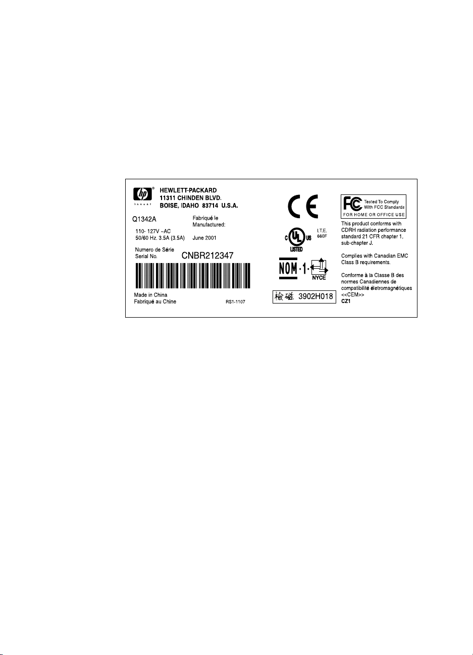
Figure 1. Model and serial number label . . . . . . . . . . . . . . . . . . .3
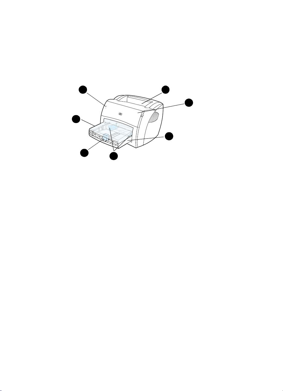
Figure 2. Front and side view . . . . . . . . . . . . . . . . . . . . . . . . . . . .6
Figure 3. Back and side view . . . . . . . . . . . . . . . . . . . . . . . . . . . .7
Figure 4. Remove the toner cartridge. . . . . . . . . . . . . . . . . . . . .15
Figure 5. Remove the media tray . . . . . . . . . . . . . . . . . . . . . . . .16
Figure 6. Remove the cable pod . . . . . . . . . . . . . . . . . . . . . . . .17
Figure 7. Remove the left side cover . . . . . . . . . . . . . . . . . . . . .18
Figure 8. Open the straight-through output door . . . . . . . . . . . .19
Figure 9. Remove the back cover. . . . . . . . . . . . . . . . . . . . . . . .20
Figure 10. Remove the ECU PCB fuse . . . . . . . . . . . . . . . . . . . .21
Figure 11. Remove the output sensor . . . . . . . . . . . . . . . . . . . . .22
Figure 12. Remove the motor (fuser removed for clarity). . . . . . .23
Figure 13. Remove the right side cover mounting screw . . . . . . .24
Figure 14. Release the right side cover tab . . . . . . . . . . . . . . . . .25
Figure 15. Remove the right side cover . . . . . . . . . . . . . . . . . . . .26
Figure 16. Disconnect the solenoid wire harness. . . . . . . . . . . . .27
Figure 17. Remove the solenoid. . . . . . . . . . . . . . . . . . . . . . . . . .28
Figure 18. Remove the top cover . . . . . . . . . . . . . . . . . . . . . . . . .29
Figure 19. Remove the connector assembly . . . . . . . . . . . . . . . .30
Figure 20. Remove the LED status panel. . . . . . . . . . . . . . . . . . .31
Figure 21. Remove the front cover mounting screws. . . . . . . . . .32
Figure 22. Remove the front cover. . . . . . . . . . . . . . . . . . . . . . . .33
Figure 23. Release the toner cartridge door connecting links . . .34
Figure 24. Remove the toner cartridge door. . . . . . . . . . . . . . . . .35
Figure 25. Remove the front guide assembly. . . . . . . . . . . . . . . .36
Figure 26. Release the front guide assembly tabs (right side) . . .37
Figure 27. Release the front guide assembly tabs (left side) . . . .38
Figure 28. Remove the transfer roller. . . . . . . . . . . . . . . . . . . . . .39
Figure 29. Disconnect the laser/scanner harnessing . . . . . . . . . .40
Figure 30. Remove the laser/scanner . . . . . . . . . . . . . . . . . . . . .41
Figure 31. Remove the right fuser bracket . . . . . . . . . . . . . . . . . .42
Figure 32. Remove the left fuser bracket . . . . . . . . . . . . . . . . . . .43
Figure 33. Remove the fuser mounting screws . . . . . . . . . . . . . .44
Figure 34. Remove the fuser assembly . . . . . . . . . . . . . . . . . . . .45
Figure 35. Remove the output rollers . . . . . . . . . . . . . . . . . . . . . .46
Figure 36. Remove the face-up rollers . . . . . . . . . . . . . . . . . . . . .47
Figure 37. Remove the gear-clutch assembly . . . . . . . . . . . . . . .48
Q1342-90910 xi

Figure 38. Remove the right plate assembly mounting screws . .49
Figure 39. Remove the pickup assembly mounting screw . . . . . .50
Figure 40. Remove the top pickup assembly mounting screws . .51
Figure 41. Remove the metal shield. . . . . . . . . . . . . . . . . . . . . . .52
Figure 42. Remove the pickup roller assembly . . . . . . . . . . . . . .53
Figure 43. Remove the paper lift plate assembly. . . . . . . . . . . . .54
Figure 44. Remove the left plate assembly . . . . . . . . . . . . . . . . .55
Figure 45. Disconnect the ECU wire harnesses. . . . . . . . . . . . . .56
Figure 46. Remove the ECU mounting screws . . . . . . . . . . . . . .57
Figure 47. Remove the ECU pan . . . . . . . . . . . . . . . . . . . . . . . . .58
Figure 48. Remove the ECU PCB from the pan. . . . . . . . . . . . . .59
Figure 49. Remove wire harnesses . . . . . . . . . . . . . . . . . . . . . . .60
Figure 50. Remove the paper-feed assembly . . . . . . . . . . . . . . .61
Figure 51. Release the paper-feed roller . . . . . . . . . . . . . . . . . . .62
Figure 52. LED status lights location . . . . . . . . . . . . . . . . . . . . . .67
Figure 53. Engine-test button. . . . . . . . . . . . . . . . . . . . . . . . . . . .79
Figure 54. Connectors for the heating element check . . . . . . . . .83
Figure 55. High-voltage connection points (right side) . . . . . . . . .84
Figure 56. High-voltage connection points (left side) . . . . . . . . . .84
Figure 57. High-voltage connector assembly (right side) . . . . . . .85
Figure 58. High-voltage connector assembly (left side) . . . . . . . .85
Figure 59. Override SW301 . . . . . . . . . . . . . . . . . . . . . . . . . . . . .86
Figure 60. Repetitive image defect ruler. . . . . . . . . . . . . . . . . . . .87
Figure 61. HP LaserJet 1000 ECU PCB. . . . . . . . . . . . . . . . . . . .88
Figure 62. Printer connectors. . . . . . . . . . . . . . . . . . . . . . . . . . . .89
Figure 63. Media tray and cable pod . . . . . . . . . . . . . . . . . . . . . .95
Figure 64. HP LaserJet 1000 covers . . . . . . . . . . . . . . . . . . . . . .96
Figure 65. Internal components (1 of 2) . . . . . . . . . . . . . . . . . . . .98
Figure 66. Internal componentsm (2 of 2) . . . . . . . . . . . . . . . . .100
Figure 67. Electrical components . . . . . . . . . . . . . . . . . . . . . . . .102
Figure 68. Paper pickup assembly (1 of 2). . . . . . . . . . . . . . . . .104
Figure 69. Paper pickup assembly (2 of 2). . . . . . . . . . . . . . . . .106
Figure 70. Fuser assembly. . . . . . . . . . . . . . . . . . . . . . . . . . . . .108
xii Chapter — Figures Q1342-90910

Tables
Table 1. HP LaserJet 1000 Series printer features . . . . . . . . . . .2
Table 2. Physical specifications . . . . . . . . . . . . . . . . . . . . . . . . . .4
Table 3. Environmental specifications . . . . . . . . . . . . . . . . . . . .4
Table 4. Power specifications . . . . . . . . . . . . . . . . . . . . . . . . . . .4
Table 5. Print operating acoustical emissions specifications . . . .5
Table 6. Skew specifications . . . . . . . . . . . . . . . . . . . . . . . . . . . .5
Table 7. Basic troubleshooting . . . . . . . . . . . . . . . . . . . . . . . . .64
Table 8. LED status lights legend . . . . . . . . . . . . . . . . . . . . . . .67
Table 9. Status lights messages . . . . . . . . . . . . . . . . . . . . . . . .68
Table 10. Error messages (no LED status panel pattern) . . . . . .70
Table 11. Solving print image-quality problems . . . . . . . . . . . . . .72
Table 12. Solving paper-feed problems. . . . . . . . . . . . . . . . . . . .77
Table 13. Engine test troubleshooting . . . . . . . . . . . . . . . . . . . . .80
Table 14. ECU connectors. . . . . . . . . . . . . . . . . . . . . . . . . . . . . .88
Table 15. Printer connectors . . . . . . . . . . . . . . . . . . . . . . . . . . . .89
Table 16. Technical support websites . . . . . . . . . . . . . . . . . . . . .92
Table 17. Accessories . . . . . . . . . . . . . . . . . . . . . . . . . . . . . . . . .93
Table 18. Common fasteners. . . . . . . . . . . . . . . . . . . . . . . . . . . .94
Table 19. Printer tray and cover. . . . . . . . . . . . . . . . . . . . . . . . . .95
Table 20. Covers . . . . . . . . . . . . . . . . . . . . . . . . . . . . . . . . . . . . .97
Table 21. Internal components (1 of 2) . . . . . . . . . . . . . . . . . . . .99
Table 22. Internal components (2 of 2) . . . . . . . . . . . . . . . . . . .101
Table 23. Electrical components . . . . . . . . . . . . . . . . . . . . . . . .103
Table 24. Paper pickup assembly (1 of 2) . . . . . . . . . . . . . . . . .105
Table 25. Paper pickup assembly (2 of 2) . . . . . . . . . . . . . . . . .107
Table 26. Fuser assembly . . . . . . . . . . . . . . . . . . . . . . . . . . . . .109
Table 27. Alphabetical parts list . . . . . . . . . . . . . . . . . . . . . . . . .110
Table 28. Numerical parts list. . . . . . . . . . . . . . . . . . . . . . . . . . .112
Q1342-90910 xiii

xiv Chapter — Tables Q1342-90910

1Product information
Chapter contents
Introduction . . . . . . . . . . . . . . . . . . . . . . . . . . . . . . . . . . . . . . .2
Printer features. . . . . . . . . . . . . . . . . . . . . . . . . . . . . . . . 2
Product specifications . . . . . . . . . . . . . . . . . . . . . . . . . . . . . . .3
Identification . . . . . . . . . . . . . . . . . . . . . . . . . . . . . . . . . .3
Overview of printer . . . . . . . . . . . . . . . . . . . . . . . . . . . . . . . . . . 6
Front and side view . . . . . . . . . . . . . . . . . . . . . . . . . . . .6
Back and side view. . . . . . . . . . . . . . . . . . . . . . . . . . . . . 7
Warranty statement . . . . . . . . . . . . . . . . . . . . . . . . . . . . . . . . . 8
Extended warranty . . . . . . . . . . . . . . . . . . . . . . . . . . . . .9
Toner cartridge information . . . . . . . . . . . . . . . . . . . . . . . . . .10
Refilled toner cartridges . . . . . . . . . . . . . . . . . . . . . . . .10
Recycling of toner cartridges . . . . . . . . . . . . . . . . . . . . 10
Q1342-90910 Chapter contents 1

Introduction
This manual contains the necessary information to service the HP
LaserJet 1000 Series printer. Service topics include printer features,
product specifications, location of model and serial numbers,
warranty information, toner cartridge information, part removal
procedures, troubleshooting procedures, and an illustrated parts
chapter.
Hint See the HP LaserJet 1000 Series printer user guide for information
about printer installation, use, and operation.
Printer features
Table 1. HP LaserJet 1000 Series printer features
Speed z 10 pages per minute (ppm) letter-size media
Resolution
Connectivity
Media handling
Toner
Duty cycle
Memory
Microsoft
®
operating
systems supported
PCL printer language
z 600 dot-per-inch (dpi) printing
z 1.1 universal serial bus (USB) port
z External cable pod (formatter)
z The HP LaserJet 1000 Series printer is
designed for use only with an IBM-compatible
computer
z 250-sheet input tray
z 125-sheet output bin
z 2500 page toner cartridge life
z 1000 page-per-month average
z 1 MB SDRAM
z Windows
z Windows
z Windows
z Windows
z Enhanced PCL 5e (with MS-DOS
®
98
2000
Millennium Edition (Me)
XP
®
emulation)
2 Chapter 1 — Product information Q1342-90910
Product specifications
Identification
The model number and serial numbers are listed on an identification
label located on the bottom of the printer. The serial number contains
information about the country of origin and the revision level,
production code, and production number of the printer. The label also
identifies power rating and regu la tor y inf ormati on.
Figure 1. Model and serial number label
Q1342-90910 Product specifications 3

Specification tables
Table 2. Physical specifications
Category Specification
Height 253 mm (10 inches)
Depth 486 mm (19.1 inches)
Width 415 mm (16.3 inches)
Weight (toner
cartridge installed)
Table 3. Environmental specifications
Category Specification
Operating
environment (printer
plugged into an ac
outlet)
Printer storage
environment (printer
not plugged into an
ac outlet)
Toner cartridge
storage environment
(printer not plugged
into an ac outlet)
7.3 kg (16.1 lb)
z Temperature: 15° to 32.5° C (59° to 90.5° F)
z Humidity: 10 to 80 percent relative humidity
(no condensation)
z Temperature: -20° to 60° C (-4° to 140° F)
z Humidity: 10 to 90 percent relative humidity
(no condensation)
z Temperature: -20° to 40° C (-4° to 104° F)
z Humidity: 10 to 90 percent relative humidity
(no condensation)
Table 4. Power specifications
Category Specification
Power
requirements
z 110 Vac (± 12 percent), 60 (± 3) Hz; 127 Vac
(± 12 percent), 60 (± 3) Hz
-Or-
z 220 Vac (± 12 percent), 50/60 (± 3) Hz
z 240 Vac (± 12 percent), 50 (± 3) Hz
WARNING! Power sources are not
interchangeable.
CAUTION To prevent damage to the
printer, always connect it to a
surge-protected power source.
4 Chapter 1 — Product information Q1342-90910

Table 4. Power specifications (continued)
Category Specification
Power consumption
(in continuous copy
mode)
Power consumption
(idle)
Power consumption
(off)
Minimum
recommended circuit
capacity
285 W
7 W
0 W
4.5 A at 115 V
2.3 A at 230 V
Table 5. Print operating acoustical emissions specifications
Category Specification
Sound power level,
(1 bel = 10 decibels)
L
WAd
Sound pressure level,
(operator position)
L
pAm
Sound pressure level,
L
(bystander position)
pAm
6.1 dB(A)
56 dB(A)
48 dB(A)
Table 6. Skew specifications
Category Specification
Print skew—left 0.8 percent (2 mm on medi a 250 mm in le ngth) for
cut-sheet me dia
1.5 percent (3.3 mm on media 220 mm in length)
for cut-sheet media
0.87 percent (1.65 mm on m edia19 0 mm in w idth)
for cut-sheet media
Print skew—right 1.5 percent (3.3 mm on media 220 mm in width)
for envelopes, pos tcards, A5, and cu t-sh eet me dia
Cut-sheet leading
edge skew
Q1342-90910 Product specifications 5
0.87 percent (1.6 mm on media 190 mm in width)
Overview of printer
Front and side view
1
7
6
Figure 2. Front and side view
1 LED status lights
2 Output bin
3 Toner cartridge door
4 Input tray
5 Sliding side media guides
6 Long media support for the input tray
7 Input tray cover
5
2
3
4
6 Chapter 1 — Product information Q1342-90910
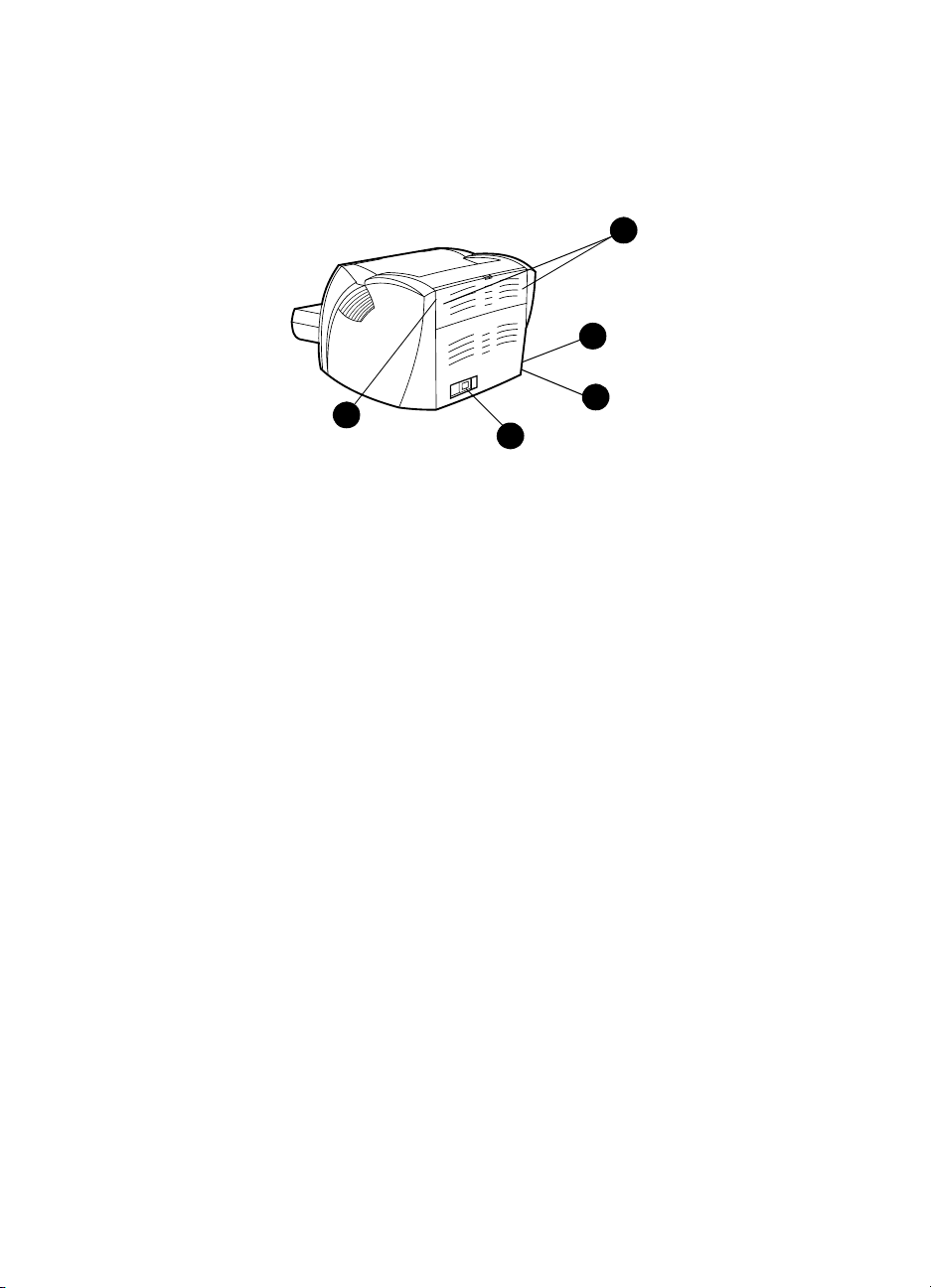
Back and side view
8
9
12
Figure 3. Back and side view
8 Media jam release levers
9 Port for the USB cable pod
10 Engine test button
11 Power receptacle
12 Straight-through output door
10
11
Q1342-90910 Overview of printer 7

Warranty statement
DURATION OF WARRANTY: One year from date of purchase
1 HP warrants to you, the end-user customer, that HP hardware, accessories, and
supplies, will be free from defects in materials and workmanship after the date of
purchase, for the period specified above. The customer is responsible for
maintaining proof of date of purchase. If HP receives notice of such defects during
the warranty period, HP will, at its option, either repair or replace products which
prove to be defective. Any replacement products may be either new or like-new,
provided that it has functionality at least equal to that of the product being
replaced.
2 HP warrants to you that HP software will not fail to execute its programming
instructions after the date of purchase, for the period specified above, due to
defects in material and workmanship when properly installed and used. If HP
receives notice of such defects during the warranty period, HP will replace
software media which does not execute its programming instructions due to such
defects.
3 HP does not warrant that the operation of HP products will be uninterrupted or
error free. If HP is unable, within a reasonable time, to repair or replace any
product to a condition as warranted, you will be entitled to a refund of the
purchase price upon prompt return of the product.
4 HP products may contain remanufactured parts equivalent to a new in
performance or may have been subject to incidental use.
5 Warranty does not apply to defects resulting from (a) improper or inadequate
maintenance or calibration, (b) software, interfacing, parts or supplies not supplied
by HP, (c) unauthorized modification or misuse, (d) operation outside of the
published environmental specifications for the product, or (d) improper site
preparation or maintenance.
6 HP MAKES NO OTHER EXPRESS WARRANTY OR CONDITION WHETHER
WRITTEN OR ORAL. TO THE EXTENT ALLOWED BY LOCAL LAW, ANY
IMPLIED WARRANTY OR CONDITION OR MERCHANTABILITY,
SATISFACTORY QUALITY, OR FITNESS FOR A PARTICULAR PURPOSE IS
LIMITED TO THE DURATION OF THE EXPRESS WARRANTY SET FORTH
ABOVE. Some countries, states or provinces do not allow limitations on the
duration of an implied warranty, so the above limitation or exclusion might not
apply to you. This warranty gives you specific legal rights and you might also have
other rights that vary from country to country, state to state, or province to
province.
8 Chapter 1 — Product information Q1342-90910

7 TO THE EXTENT ALLOWED BY LOCAL LAW, THE REMEDIES IN THIS
WARRANTY STATEMENT ARE YOUR SOLE AND EXCLUSIVE REMEDIES.
EXCEPT AS INDICATED ABOVE, IN NO EVENT WILL HP OR ITS SUPPLIERS
BE LIABLE FOR LOSS OF DATA OR FOR DIRECT, SPECIAL, INCIDENTAL,
CONSEQUENTIAL (INCLUDING LOST PROFIT OR DATA), OR OTHER
DAMAGE, WHETHER BASED IN CONTRACT, TORT, OR OTHERWISE. Some
countries, states or provinces do not allow the exclusion or limitation of incidental
or consequential damages, so the above limitation or exclusion may not apply to
you.
FOR CONSUMER TRANSACTIONS IN AUSTRALIA AND NEW ZEALAND; THE
WARRANTY TERMS CONTAINED IN THIS STATEMENT, EXCEPT TO THE
EXTENT LAWFULLY PERMITTED, DO NOT EXCLUDE, RESTRICT OR
MODIFY AND ARE IN ADDITION TO THE MANDATORY STATUTORY RIGHTS
APPLICABLE TO THE SALE OF THIS PRODUCT TO YOU.
Extended warranty
HP SupportPack provides coverage for the HP hardware product and
all HP-supplied internal components. The hardware maintenance
warranty covers a three-year period from the date of the HP product
purchase. The customer must purchase the HP SupportPack
(document number is 9036) within 180 days of the HP product
purchase. Customers can contact the nearest HP-authorized dealer
about this service.
Q1342-90910 Warranty statement 9

Toner cartridge information
The toner cartridge is designed to simplify replacement of the major
consumable parts. The toner cartridge contains the printing
mechanism and a supply of toner.
At five percent page coverage, a toner cartridge prints approximately
2500 pages. However, a toner cartridge should print more pages if it
regularly prints pages with less coverage, such as short memos. The
cartridge might print fewer pages if heavy or bold print is used.
For best results, always use a toner cartridge before the expiration
date stamped on the toner cartridge box.
Refilled toner cartridges
Although Hewlett-Packard does not prohibit the use of refilled toner
cartridges during the warranty period or while the printer is under a
maintenance contract, it is not recommended for the following
reasons:
z Repairs resulting from the use of refilled toner cartridges are not
covered under Hewlett-Packard warranty or maintenance
contracts.
z Hewlett-Packard has no control or process to ensure that a
refilled toner cartridge functions at the high level of reliability of a
new HP LaserJet toner cartridge. Hewlett-Packard also cannot
predict the long-term reliability effect on the printer from using
different toner formulations found in refilled cartridges.
z The print quality of HP LaserJet toner cartridges influences the
customer’s percepti on of the printer . Hewl ett-P ack ar d has no
control over the actual print quality of a refilled toner cartridge.
Recycling of toner cartridges
In order to reduce waste, Hewlett-Packard offers a recycling program.
Cartridge components that do not wear out are recycled. Plastics and
other materials are recycled. Hewlett-Packard pays the shipping
costs from the user to the recycling plant (within the United States).
To join this recycling effort, follow the instructions inside the toner
cartridge box.
10 Chapter 1 — Product information Q1342-90910

Removal and
2
replacement
Chapter contents
Required tools . . . . . . . . . . . . . . . . . . . . . . . . . . . . . . . . . . . .13
Before performing service . . . . . . . . . . . . . . . . . . . . . .13
Toner cartridge . . . . . . . . . . . . . . . . . . . . . . . . . . . . . . .15
Parts removal order . . . . . . . . . . . . . . . . . . . . . . . . . . . 14
Toner cartridge. . . . . . . . . . . . . . . . . . . . . . . . . . . . . . . . . . . .15
Left side cover . . . . . . . . . . . . . . . . . . . . . . . . . . . . . . .18
Back cover . . . . . . . . . . . . . . . . . . . . . . . . . . . . . . . . . . 19
Back cover . . . . . . . . . . . . . . . . . . . . . . . . . . . . . . . . . . 19
ECU PCB fuse . . . . . . . . . . . . . . . . . . . . . . . . . . . . . . . 21
Motor . . . . . . . . . . . . . . . . . . . . . . . . . . . . . . . . . . . . . .23
Solenoid . . . . . . . . . . . . . . . . . . . . . . . . . . . . . . . . . . . .27
Connector PCB Assembly . . . . . . . . . . . . . . . . . . . . . . 30
Front cover . . . . . . . . . . . . . . . . . . . . . . . . . . . . . . . . . .32
Toner cartridge door. . . . . . . . . . . . . . . . . . . . . . . . . . . 34
Front guide . . . . . . . . . . . . . . . . . . . . . . . . . . . . . . . . . .36
Internal assemblies . . . . . . . . . . . . . . . . . . . . . . . . . . . . . . . .39
Transfer roller . . . . . . . . . . . . . . . . . . . . . . . . . . . . . . . .39
Laser/scanner assembly. . . . . . . . . . . . . . . . . . . . . . . .40
Output rollers . . . . . . . . . . . . . . . . . . . . . . . . . . . . . . . . 46
Face-up roller . . . . . . . . . . . . . . . . . . . . . . . . . . . . . . . .47
Right plate assembly . . . . . . . . . . . . . . . . . . . . . . . . . . 48
Right plate assembly . . . . . . . . . . . . . . . . . . . . . . . . . . 48
Right plate assembly . . . . . . . . . . . . . . . . . . . . . . . . . . 48
Q1342-90910 Chapter contents 11

Pickup assembly . . . . . . . . . . . . . . . . . . . . . . . . . . . . . . . . . 50
Pickup roller assembly. . . . . . . . . . . . . . . . . . . . . . . . . . . . .53
Paper lift plate assembly . . . . . . . . . . . . . . . . . . . . . . . . . . .54
Left plate assembly . . . . . . . . . . . . . . . . . . . . . . . . . . . . . . .55
Bottom assemblies . . . . . . . . . . . . . . . . . . . . . . . . . . . . . . . . . . . .56
ECU pan . . . . . . . . . . . . . . . . . . . . . . . . . . . . . . . . . . . . . . .56
Paper-feed assembly. . . . . . . . . . . . . . . . . . . . . . . . . . . . . .60
12 Chapter 2 — Removal and replacement Q1342-90910

Removal and replacement strategy
This chapter documents the removal and replacement of field
replaceable units (FRUs) only. Replacement is generally the reverse
of removal. Occasionally, notes and hints are included to provide
directions for difficult or critical replacement procedures.
WARNING! Unplug the power cord from the power source before servicing the
printer. Failure to follow this warning can result in personal injury or
damage to the printer. Certain functional checks during troubleshooting
require power supplied to the printer. However, power should be
disconnected when removing assemblies.
Never operate the printer with the laser/scanner assembly exposed.
The reflected beam, although invisible, can damage your eyes. When
servicing the printer, replace the top cover before operating the printer.
CAUTION The printer contains electrostatic discharge (ESD) sensitive
components. Always perform service work at an ESD-protected
workstation. If an ESD-protected workstation is not available,
discharge body static and ground the printer chassis before servicing
the printer.
Required tools
z #2 Phillips screwdriver with magnetic tip
z Small flat-blade screwdriver
z Needle-nose pliers
z penlight (optional)
Note Use of a Posidrive screwdriver damages screw-heads on the printer.
Use a #2 Phillips screwdriver.
Hint To install a self-tapping screw, first turn it counterclockwise to align it
with the existing thread pattern, then carefully turn it clockwise to
tighten. Do not overtighten.
Before performing service
z Unplug the power cable and remove all media from the printer.
z Place the printer on an ESD mat or discharge body static and
ground the printer chassis.
z Remove the toner cartridge and media tray. See “Toner
cartridge” on page 15 and “Media tray” on page 16.
Q1342-90910 Removal and replacement strategy 13

Parts removal order
Use the following diagram to determine the order in which parts must
be removed.
Toner
cartridge
Media tray
Cable pod
Left side cover
Back cover
ECU PCB fuse
Output sensor
Motor
Right cover
Transfer roller Solenoid
Top Cover
LED status panel
Connector PCB
Front cover
Toner cartridge door
Front guide
Fuser assembly (see note)
Right plate assembly
Pickup assembly
Pickup roller
Paper lift
Left plate assembly
Laser/scanner assembly
Fuser assembly
Face-down roller
Face-up roller
ECU pan
Paper feed assembly
Note The fuser assembly is intentionally listed twice.
14 Chapter 2 — Removal and replacement Q1342-90910
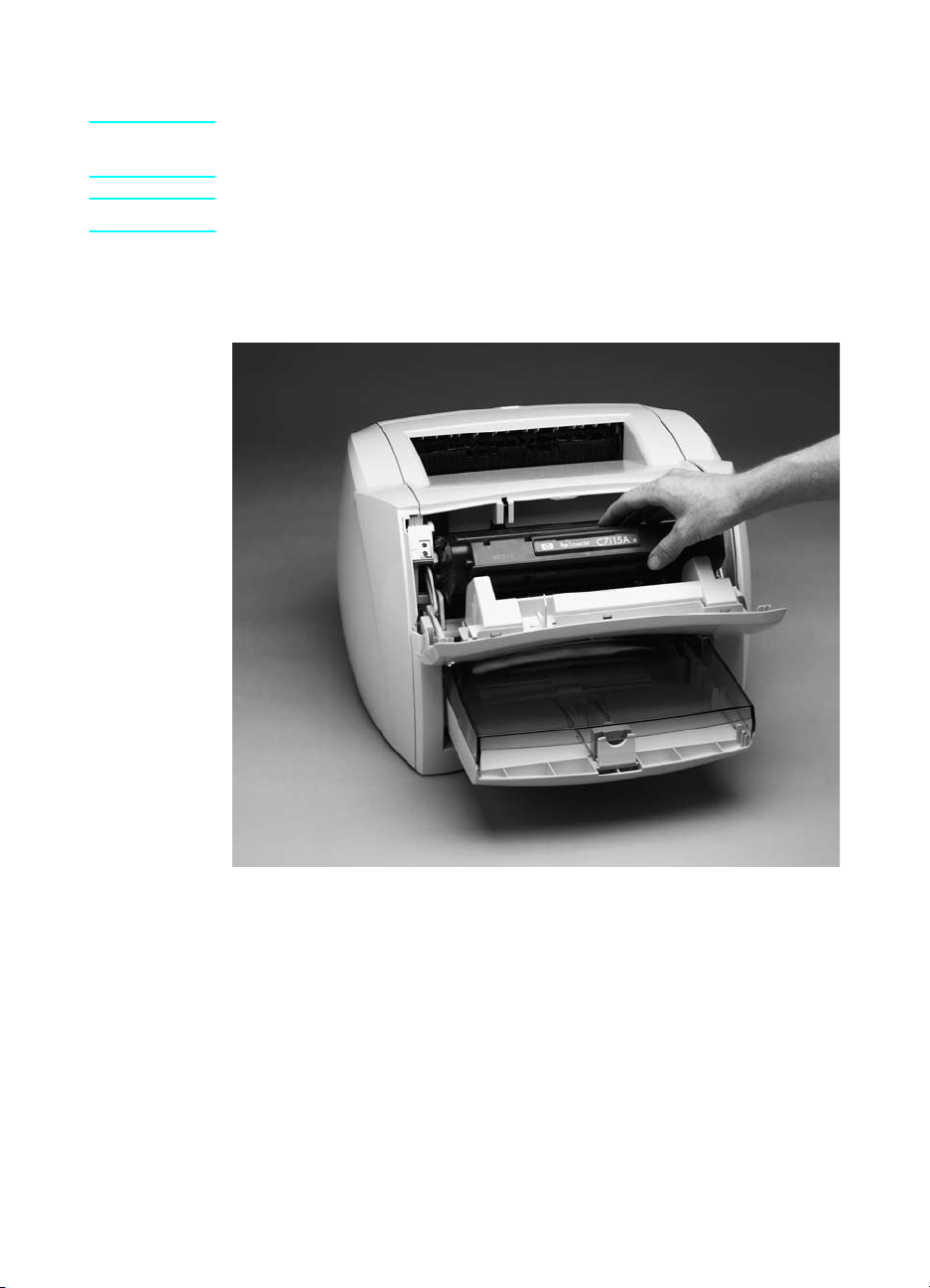
Toner cartridge
CAUTION To prevent damage, do not expose the toner cartridge to light. Cover
it with a piece of paper.
Note You will feel resistance when you open the toner cartridge door.
1 Open the toner cartridge door.
2 Remove the toner cartridge.
Figure 4. Remove the toner cartridge
Q1342-90910 Removal and replacement strategy 15
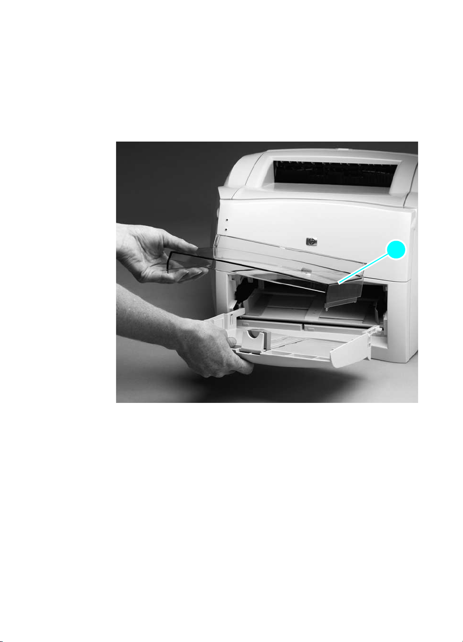
External assemblies
Media tray
1 Lift off the media tray cover (callout 1).
2 Slightly tilt up the media tray and pull it away from the printer.
11
Figure 5. Remove the media tray
16 Chapter 2 — Removal and replacement Q1342-90910
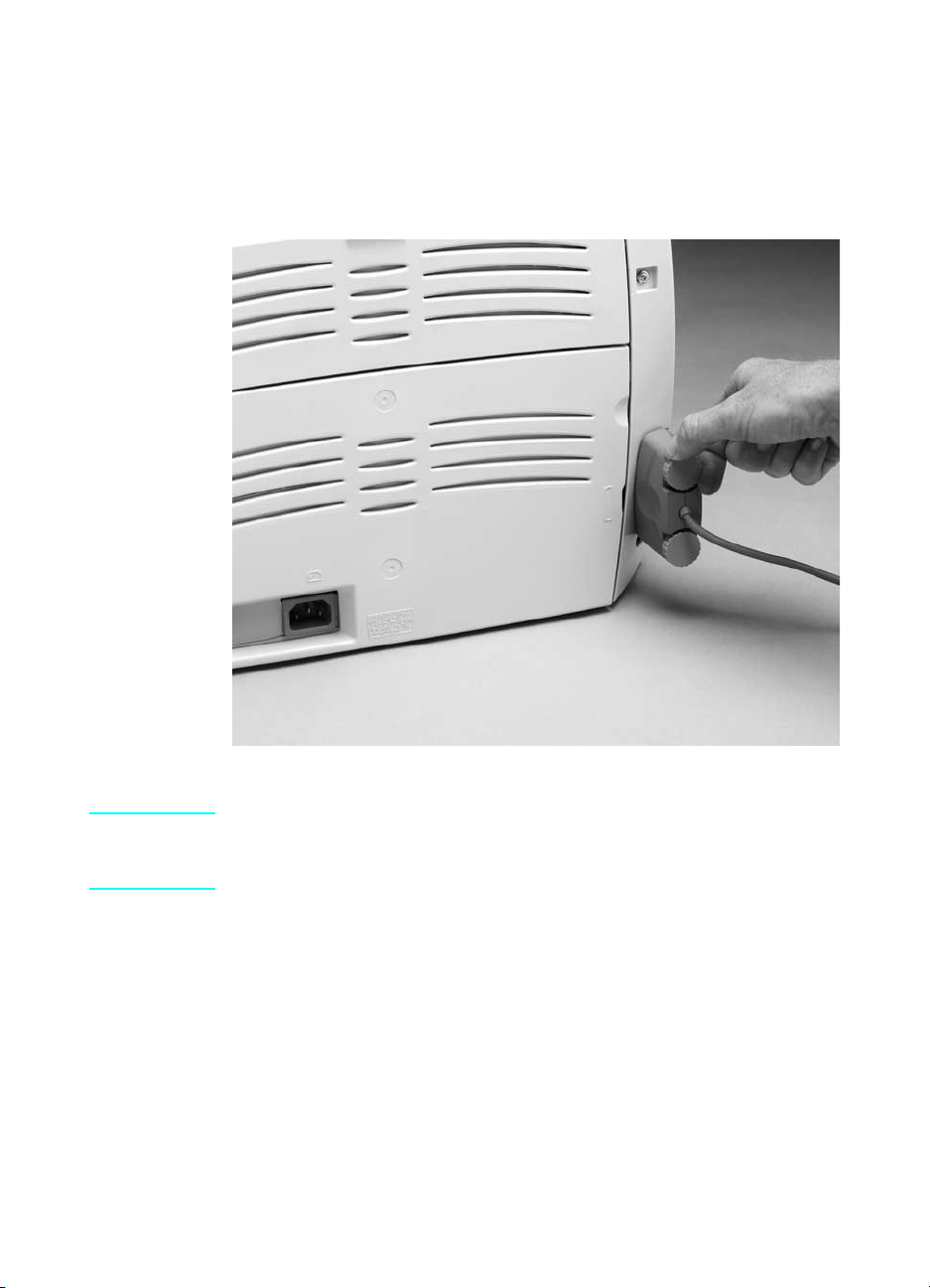
Cable pod
1 Turn the two pod thumbscrews counterclockwise until they turn
freely.
2 Grasp the pod, and gently pull it away from the printer.
Figure 6. Remove the cable pod
Hint For easier installation, start tightening the top thumbscrew (do not fully
tighten) and then tighten the bottom thumbscrew when replacing the
cable pod. Make sure to fully tighten both thumbscrews.
Q1342-90910 External assemblies 17
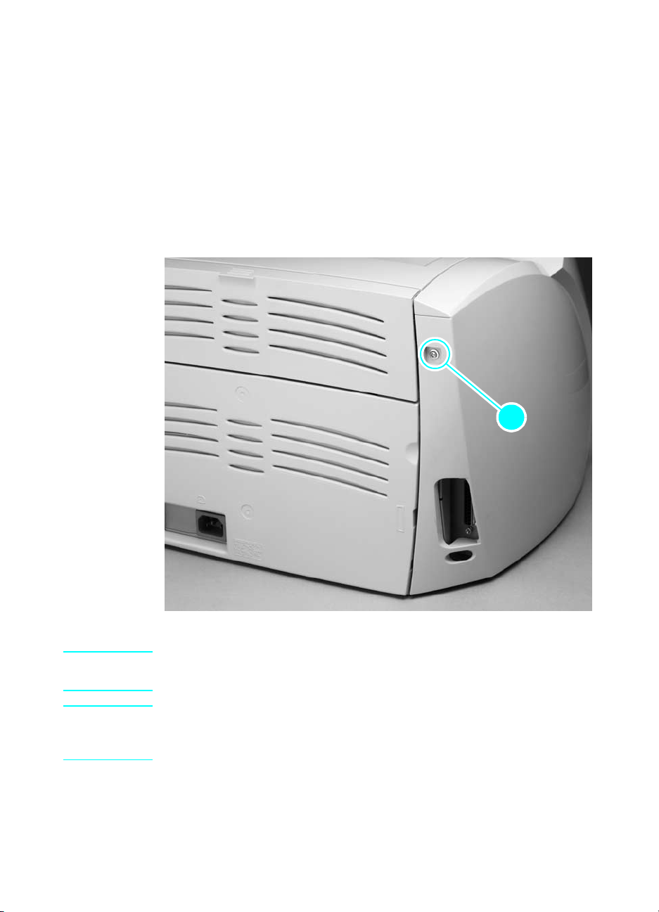
Left side cover
1 Remove the following assemblies:
z Toner cartridge, media tray, and cable pod. See “Toner cartridge”
on page 15 throu gh “Cable pod” on page 17.
2 Open the toner cartridge door.
3 Remove the single left-cover retaining screw (callout 1).
4 Pull out on the rear of the cover and rotate it away from the
printer.
11
Figure 7. Remove the left side cover
Hint It might be necessary to release the left side cover-locking tab found
under the printer.
Hint The left-side retaining screw is slightly longer than similar screws used
in the printer. Keep this screw separated from other screws while
servicing the printer to avoid misplacing it.
18 Chapter 2 — Removal and replacement Q1342-90910
Loading…
-
Драйверы
5
-
Руководства по ремонту
1
-
Инструкции по эксплуатации
18
Языки:
HP LaserJet 1000 инструкция по эксплуатации
(112 страниц)
- Языки:Русский
-
Тип:
PDF -
Размер:
1.68 MB -
Описание:
Лазерный принтер
Просмотр
HP LaserJet 1000 инструкция по эксплуатации
(104 страницы)
- Языки:Английский
-
Тип:
PDF -
Размер:
1.38 MB
Просмотр
HP LaserJet 1000 инструкция по эксплуатации
(104 страницы)
- Языки:Турецкий
-
Тип:
PDF -
Размер:
1.75 MB
Просмотр
HP LaserJet 1000 инструкция по эксплуатации
(108 страниц)
- Языки:Греческий
-
Тип:
PDF -
Размер:
1.68 MB
Просмотр
HP LaserJet 1000 инструкция по эксплуатации
(116 страниц)
- Языки:Тайский
-
Тип:
PDF -
Размер:
3.48 MB
Просмотр
HP LaserJet 1000 инструкция по эксплуатации
(102 страницы)
- Языки:Арабский
-
Тип:
PDF -
Размер:
2.15 MB
Просмотр
HP LaserJet 1000 инструкция по эксплуатации
(104 страницы)
- Языки:Шведский
-
Тип:
PDF -
Размер:
1.55 MB
Просмотр
HP LaserJet 1000 инструкция по эксплуатации
(108 страниц)
- Языки:Французский
-
Тип:
PDF -
Размер:
1.7 MB
Просмотр
HP LaserJet 1000 инструкция по эксплуатации
(108 страниц)
- Языки:Немецкий
-
Тип:
PDF -
Размер:
1.87 MB
Просмотр
HP LaserJet 1000 инструкция по эксплуатации
(104 страницы)
- Языки:Венгерский
-
Тип:
PDF -
Размер:
1.64 MB
Просмотр
HP LaserJet 1000 инструкция по эксплуатации
(104 страницы)
- Языки:Чешский
-
Тип:
PDF -
Размер:
2.03 MB
Просмотр
HP LaserJet 1000 инструкция по эксплуатации
(104 страницы)
- Языки:Словацкий
-
Тип:
PDF -
Размер:
2.05 MB
Просмотр
HP LaserJet 1000 инструкция по эксплуатации
(108 страниц)
- Языки:Нидерландский
-
Тип:
PDF -
Размер:
1.52 MB
Просмотр
HP LaserJet 1000 инструкция по эксплуатации
(104 страницы)
- Языки:Датский
-
Тип:
PDF -
Размер:
1.5 MB
Просмотр
HP LaserJet 1000 инструкция по эксплуатации
(103 страницы)
- Языки:Иврит
-
Тип:
PDF -
Размер:
3.01 MB
Просмотр
HP LaserJet 1000 инструкция по эксплуатации
(108 страниц)
- Языки:Польский
-
Тип:
PDF -
Размер:
1.69 MB
Просмотр
HP LaserJet 1000 инструкция по эксплуатации
(104 страницы)
- Языки:Финский
-
Тип:
PDF -
Размер:
1.71 MB
Просмотр
HP LaserJet 1000 инструкция по эксплуатации
(104 страницы)
- Языки:Корейский
-
Тип:
PDF -
Размер:
1.78 MB
Просмотр
На NoDevice можно скачать инструкцию по эксплуатации для HP LaserJet 1000. Руководство пользователя необходимо для ознакомления с правилами установки и эксплуатации HP LaserJet 1000. Инструкции по использованию помогут правильно настроить HP LaserJet 1000, исправить ошибки и выявить неполадки.
Содержание статьи
- 1 Описание HP 1000
- 2 Основные характеристики HP LaserJet 1000
- 3 Принтеры серии LaserJet 1000
- 4 Установка и программное обеспечение
- 5 Распространенные проблемы
- 6 Инструкции
- 7 Совместимые запчасти
- 8 Отзывы об HP LaserJet 1000
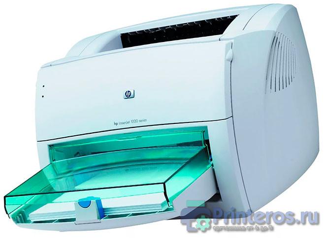
HP LaserJet 1000 — аппарат, предназначенный для офисной работы со средней степенью загрузки. Модель уже сильно устарела и давно снята с производства. Принтеры серии HP LaserJet 1000 это довольно простые устройства, лишенные каких-либо дополнительных функций. В целом довольно надежный аппарат. Среди неисправностей — проблемы с механикой (на устройствах с большими пробегами), выход из строя термоузла (по вине пользователя).
Основные характеристики HP LaserJet 1000
- Общие параметры
Производитель: HP
Серия: LaserJet
Модель: LaserJet 1000
Тип устройства: Принтер
Размещение: настольный
Область применения: персональный
Ежемесячная нагрузка: желательная от 6500 до 7000 страниц
- Параметры печати
Максимальный формат: A4
Технология печати: лазерная
Цветность: черно-белая
Количество цветов: один
Max разрешение печати dpi (ч/б): 600×600
Max скорость печати (ч/б): 12 стр./мин. A4
Время выхода первой страницы (ч/б): 10 cек
Поля: по 4 мм. сверху, снизу, слева и справа
- Используемые носители/бумага
Емкость лотка подачи бумаги: 250 лист.
Емкость выходного лотка бумаги: 125 лист.
Емкость лотка для ручной подачи: 1 лист.
Плотность бумаги: 60-163 г/м2
Носители: пленка, этикетки, глянцевая бумага, конверты, матовая бумага
- Расходные материалы / заменяемые компоненты
Тип расходного материала: картридж
Черный картридж: C7115A (15A), C7115X (15X) (большой ресурс)
Количество картриджей: один
Ресурс картриджей — тонеров: 2500 стр. и 3500 стр. ресурс C7115X
- Технические характеристики
Тип процессора: RISC
Частота процессора: 48 МГц
Рзъемы/интерфейсы: USB
Память: 1 Мб
Поддержка PostScript: нет данных
Поддержка шрифтов: нет данных
Совместимость с ОС: Windows 98 / ME / Windows 2000 / Windows XP (32 бита) / на более свежих ОС могут возникнуть проблемы при установке
MIN требования: компьютер с ЮСБ и с 32 Mb памяти
- Энергоэффективность/шум
Потребляемая при печати мощность: 213 Вт
Потребляемая в режиме ожидания мощность: 7 Вт
Тип блока питания: встроенный
Сеть: 220 В
Уровень шумов при печати: 52 дБ
- Размеры и вес
Высота (см): 25
Длина(см): 49
Ширина (см): 42
Размеры упаковки (см): 32.6 x 46 x 48.3
Вес (грамм): 7250
Вес в коробке (брутто) (грамм): 10050
Принтеры серии LaserJet 1000
Серия принтеров включает в себя только один принтер, следующие модели (LJ 1150/1200/1300) обладают аналогичной конструкцией, имеют возможность печати конфигурации с кнопки и отличаются улучшенными характеристиками
Установка и программное обеспечение
Инструкция по установке драйвера
Скачать драйвер hp 1000 для windows
Распространенные проблемы
- Одной из самых частых поломок HP 1000 является выход из строя термоузла. Печь аппарата может выйти из строя как вследствие естественного износа, так и по вине пользователя (попадание в устройство скрепок от степлера и других инородных предметов).
- Часто встречается проблема, когда на hp 1000 сползает в сторону термопленка, основная причина — износ бушингов резинового вала.
- Так как принтер уже довольно старый часто встречаются проблемы с механикой
Инструкции
- Принтер hp laserjet 1000 инструкция пользователя — скачать [Ru]
- Сервисный мануал HP laserjet 1000 — скачать [Eng]
- Печать внутреннего теста «Матроски» — найдите отверстие, расположенное под интерфейсным разъемом принтера. В нем расположена кнопка, запускающая печать матроски.
Совместимые запчасти
- Резиновый вал № RF0-1002 подходит также к LJ 1200, 1150, 1300 и к Canon PC D320
- Термопленка подходит от практически всех принтеров HP с аналогичным термоэлементом. Можно устанавливать от HP 1200/1010 и т.д. Хорошо себя зарекомендовала «Термопленка HP LJ 1300/1320/1160 (П,U)»
Отзывы об HP LaserJet 1000
HP LJ 1000 зарекомендовал себя как надежный аппарат. Основная проблема, с которой сталкиваются пользователи — это отсутствие драйверов на свежие версии Windows и низкая скорость работы. Среди положительных качеств отмечают ресурс и надежность картриджа, а также возможность установить картридж с повышенным ресурсом.
Ниже в комментариях вы можете оставить отзыв об аппарате этой модели
Оценка статьи:
Загрузка…
2
Краткий обзор принтера HP
•
Компоненты принтера
•
Кнопка Вкл
Компоненты принтера
1 Входной лоток
2 Направляющая ширины бумаги
3 Кнопка Вкл. Включение и выключение устройства. Когда питание выключено, устройство
по-прежнему потребляет небольшое количество энергии. Чтобы полностью отключить
питание, выключите устройство и отсоедините кабель питания.
4 Выходной лоток
5 Удлинитель выходного лотка (также называется удлинителем лотка)
6 Крышка картриджа
7 Картриджи
8 Порт USB
9 Разъем питания (используйте только вместе с адаптером питания, поставляемым НР)
Кнопка Вкл
Краткий обзор принтера HP
5
Кра
ткий
об
зор
пр
ин
тера
HP
•
Если устройство включено, индикатор кнопки Вкл будет светиться.
•
Если устройство обрабатывает задание, индикатор кнопки Вкл будет мигать.
•
Если индикатор кнопки Вкл мигает очень часто, принтер находится в состоянии
ошибки, которую можно устранить с помощью сообщений на экране. Если на
экране нет сообщений, попробуйте напечатать документ, чтобы появилось
сообщение.
•
Если было устранено замятие бумаги или в принтере закончилась бумага, для
возобновления печати нажмите кнопку Вкл.
Глава 2
6
Краткий обзор принтера HP
Кр
ат
кий
обзо
р
принте
ра
HP
3
Печать
Для продолжения выберите задание печати.
«Печать документов» на стр. 7
«Печать фотографий» на стр. 8
«Печать на конвертах» на стр. 9
Печать документов
Как печатать из программы
1.
Убедитесь, что выходной лоток открыт.
2.
Убедитесь, что во входной лоток загружена бумага.
3.
В используемой программе щелкните кнопку Печать.
4.
Убедитесь, что устройство выбрано в качестве принтера.
5.
Нажмите кнопку, с помощью которой открывается диалоговое окно Свойства.
В зависимости от используемого программного приложения эта кнопка может
называться Свойства, Параметры, Настройка принтера, Принтер или
Предпочтения.
Печать
7
Печать
6.
Выберите соответствующие параметры.
•
На вкладке Макет выберите ориентацию страницы: Книжная или
Альбомная.
•
На вкладке Бумага/Качество выберите тип и качество бумаги в
раскрывающемся списке Носитель.
•
Щелкните Дополнительно, чтобы выбрать соответствующий размер
бумаги в списке Бумага/Вывод.
7.
Щелкните OK, чтобы закрыть диалоговое окно Свойства.
8.
Щелкните Печать или OK, чтобы начать печать.
Примечание.
Можно выполнять печать не только с одной стороны, но и с
обеих сторон листа. Щелкните кнопку Дополнительно на вкладке Бумага/
Качество или Макет. В раскрывающемся списке Печатаемые страницы
выберите Печатать только нечетные страницы. Для печати щелкните OK.
После того как все нечетные страницы документа напечатаны, извлеките листы
из выходного лотка. Поместите эти листы во входной лоток чистой стороной
вверх. В раскрывающемся списке Печатаемые страницы выберите Печатать
только четные страницы. Для печати щелкните OK.
Печать фотографий
Как напечатать фотографию на фотобумаге
1.
Убедитесь, что выходной лоток открыт.
2.
Извлеките всю бумагу из входного лотка, а затем загрузите фотобумагу
стороной для печати вверх.
Примечание.
Если на используемой фотобумаге имеются
перфорированные полоски, загружайте фотобумагу полосками вверх.
3.
В меню Файл используемого приложения выберите Печать.
4.
Убедитесь, что устройство выбрано в качестве принтера.
5.
Нажмите кнопку, с помощью которой открывается диалоговое окно Свойства.
В зависимости от используемого программного приложения эта кнопка может
называться Свойства, Параметры, Настройка принтера, Принтер или
Предпочтения.
Глава 3
8
Печать
Печать
Нажмите на кнопку для помощи
EC-JET1000 User Manual.pdf
EC Series Laser Coders User Manual.pdf
EC-JET2000 User Manual.pdf
ECH500_User manual_V1.pdf
- 1
Products
Continuous Inkjet Printer
EC-JET 2000
EC-JET1000
EC-JET 900
EC-JET 500
EC-JET 400
EC-JET 300
EC-JET1000Pro
Laser Coding System
ECL1100
ECL6100
ECL7000
FOMONE
High Resolution Inkjet Printer
ECH900
ECH800
ECH700
ECH500
Handheld ECH200Pro
ECH510
Thermal Transfer Inkjet Printer
Large Character Inkjet Printer
Consumables
CIJ Consumables Ink&Solvent
Ink Cartridge
Other Related Products
Labelling
Conveyor
Trace And Track System
Industry Applications
Building Materials & Others
-

-
电话
Created with Sketch.+86 20 8220 9518
-
邮箱1
Created with Sketch.sales@ecjetprinter.com
-
返回顶部2
Created with Sketch.
