
Инструкция по работе с Краскопультом электрический BOSCH PFS 55.
ПРЕДУПРЕЖДЕНИЕ
Прочтите все указания по технике безопасности и инструкции, включая памятки по безопасности, поставленные для красок и растворителей, и предупредительные таблички на емкостях. Упущения, допущенные при соблюдении предписаний по технике безопасности и инструкций могут вызвать поражение электрическим током, пожар и/или привести к несчастным случаям и тяжелым травмам.
Сохраните эти указания по безопасности и инструкции для будущей пользы. Использованное в предписаниях по технике безопасности определение «электроинструмент» распространяется на электроинструмент с питанием от сетевого напряжения (с шнуром питания от сети) и на электроинструмент с аккумулятрами (без шнура питания от сети).
1) Безопасность рабочего места а) Содержите Ваше рабочее место в чистоте, порядке и хорошо освещенным. Беспорядок или любые неосвещенные участки рабочего места способны привести к травмам или несчастным случаям. б) При работе с электроинструментом не подпускайте близко детей и других лиц. При отвлечении Вы можете утратить контроль над электроинструментом.
2) Электробезопасность
а) Штепсельная вилка вашего электроинструмента должна подходить к штепсельной сетевой розетке. Никоим образом не видоизменяйте штепсельную вилку. Не применяйте какие-либо переходные штекеры для электроинструментов имеющих защитное заземление. Неизмененные штепсельные вилки а также подходящие штепсельные розетки существенно снижают риск поражения персонала электрическим током.
б) Предотвращайте любой телесный контакт с заземленными поверхностями, с трубами, элементами отопления,кухонными плитами, холодильниками и т. д. При заземлении Вашего тела существенно повышается риск поражения электрическим током.
в) Защищайте электроинструмент от сырости и дождя. Присуствие воды в электроинструмент повышает риск поражения человека электрическим током.
г) Не допускается использование шнура не по назначению, к примеру, для транспортировки либо подвески электроинструмента, или для отсоединения вилки из штепсельной розетки. Предохраняйте шнур от воздействия высоких температур, острых кромок, масла либо подвижных частей электроинструмента. Поврежденный либо спутанный шнур повышает риск поражения персонала электротоком.
д) При работе с применением электроинструмента под открытым небом применяйте предназначенные для этого кабели-удлинители. Применение пригодного для эксплуатации под открытым небом кабеля-удлинителя понижает риск поражения электротоком.
е) Если не представляется возможным избежать использования электроинструмента в сыром помещении, то устанавливайте специальный выключатель для защиты от токов повреждения. Использование выключателя защиты от токов повреждения существенно снижает риск электрического поражения пользователя. 3) Безопасность людей
а) Будьте внимательными, внимательно следите за тем, что Вы делаете и начинайте работу с электроинструментом продуманно. Никогда не работайте с электроинструментом в усталом состоянии либо, если Вы находитесь под негативным влиянием наркотиков, спиртных напитков либо лекарств. Любой момент невнимательности при работе с электроинструментом способен привести к серьезным травмам.
б) Пользуйтесь средствами индивидуальной защиты и всегда носите защитные очки.
Применяйте средства индивидуальной защиты, защитную маску и спецобувь. Защитная каска и средства защиты органов слуха, согласно виду конкретной работы, снижают риск травмирования.
в) Предотвращайте непреднамеренное включение. Перед подключением электроинструмента к электрической сети и/или к аккумулятору убедитесь в выключенном состоянии самого электроинструмента. Если Вы при транспортировании электроинструмента держите палец на выключателе либо подключенный электроинструмент включаете в сеть питания, то это способно привести к несчастному случаю.
г) Держите Ваше тело в естественном, удобном положении. Всегда занимайте саксимально устойчивое положение и всегда выдерживайте равновесие. Благодаря этому Вы сможете лучше контролировать электроинструмент в любых неожиданных ситуациях.
д) Носите подходящую одежду. Не надевайте широкую одежду, а также украшения. Держите волосы, перчатки и одежду в стороне от любых движущихся частей.
Широкая одежда, украшения либо длинные волосы могут быть затянуты вращающимися мечанизмами и частями.
4) Применение и обхождение с электроинструментом
а) Не перегружайте электроинструмент. Применяте для Вашей работы предназначенный конкретно для этого электроинструмент. С подходящим электроинструментом Вы будете работаеть лучше и надежнее в указанном диапазоне мощностей.
б) Не эксплуатируйте электроинструмент с неисправным выключателем.
Электроинструмент, который не поддается прямому включению либо выключению, опасен и должен быть срочно отремонтирован. в) До начала непосредственной наладки электроинструмента, замены принадлежностей либо прекращения работы отключайте вилку от розетки сети и/или выньте из него аккумулятор. Эта мера предосторожности предотвращает непреднамеренный запуск электроинструмента.
г) Храните неиспользуемые электроинструменты в месте, недоступном для детей. Не разрешайте пользоваться данным инструментом лицам, которые незнакомы с ним или не читали настоящих предписаний. Электроинструменты особо опасны в руках неопытных людей.
д) Тщательно ухаживайте за вашим электроинструментом. Проверяйте безупречную функцию, а также ход движущихся частей и механизмов электроинструмента, отсутствие каких-либо поломок или повреждений, отрицательно влияющих на функциональность электроинструмента. Поврежденные части необходимо отремонтировать до непосредственного использования электроинструмента. Ненадлжащее обслуживание электроинструментов является причиной большого числа травм и несчастных случаев.
е) Применяйте электроинструмент, принадлежности, рабочие инструменты и прочее в полном соответствии с настоящими инструкциями. Учитывайте при этом любые рабочие условия и выполняемую работу.
Применение электроинструментов для непредусмотренных работ способно привести к опасным ситуациям.
5) Сервис
а) К ремонту Вашего электроинструмента допускайте только квалифицированный персонал и только с применением оригинальных запасных мечанизмов и частей. Этим обеспечивается сохранность безопасности вашего электроинструмента.
Указания по безопасности для систем тонкого распыления
Безопасность рабочего места
► Содержите Ваше рабочее место в чистоте и с хорошим освещением. Убирайте емкости для краски или растворителя, ветошь и все горючие материалы.
Возможная опасность самовоспламенения. Постоянно держите поблизости в готовности работоспособные огнетушители и другие устройства пожаротушения.
► Обеспечивайте приемлимую вентиляцию на участке распыления и хорошую подачу свежего воздуха по всей площади помещения. Испарения горючих растворителей и разбавителей создают взрывоопасную атмосферу.
► Никогда не применяйте для распыления и очистки горючие материалы температура воспламенения которых ниже 21 °C. Применяйте жидкости и материалы на водной основе, на основе труднолетучих углеводородов либо подобные материалы. Легколетучие, испаряющиеся растворители создают в помещениях взрывоопасную атмосферу.
► Не распыляйте непосредственно в пределах источников возгорания, как то, статических открытого пламени, электроискр, инициирующего пламени, горячих предметов, сигарет, двигателей, и искр от сочленения и расчленения электрокабелей или задействования выключателей. Такие источники искр способны привести к воспламенению атмосферы.
► Не распыляйте те материалы, опасность которых вам неизвестна. Незнакомые материалы могут создавать опасные условия.
Безопасность людей
► Применяйте дополнительные, индивидуальные, средства защиты, как то, соответствующие защитные или дыхательные фильтр-маски, защитные перчатки при распылении различных химических веществ и непосредственной работе с ними. Применение индивидуальных защитных средств для соответствующих условий понижает возможность воздействия опасных веществ.
► Не направляйте распыляющую инструментом струю на себя, других людей либо животных. Держитесь вдали от распыляемой струи. Если распыляющая струя пробьет кожные покровы, то немедленно обратитесь к врачу. Струя способна пробить кожу даже сквозь перчатки и впрыснуть Вам распыляемое вещество.
► Ни в коем случае не рассматривайте такое впрыскивание как обычное ранение кожи. Струя высокого давления способна впрыснуть Вам различные ядовитые вещества и привести к серьезным травмам. В случае впрыска через кожу немедленно обратитесь к врачу за мед помощью.
► Учитывайте все возможные опасности, исходящие от распыляемого вами вещества. Учитывайте маркировку на самих емкостях или информации изготовителя распыляемого вами вещества, включая требование к применению индивидуальных защитных средств. Выполняйте указания изготовителя, чтобы понизить риск получения травм, вызванных ядами, пожаром, канцерогенами и т. п.
Применение электроинструмента и обхождение с ним
► Применяйте только специфицированные заводом изготовителем наборы сопел. Никогда не работайте с данным распылителем без оборудованной сопловой защиты.
Использование специального соплового набора с соответствующей сопловой защитой существенно снижает вероятность пробоя кожи струей воздуха высокого давления и впрыскивания ядовитых веществ.
► Осторожно при очистке и смене сопловых наборов. Если при распылении засорится сопловый набор, то перед удалением сопла для очистки выполните указания изготовителя по выключению инструмента и снятию давления. Под высоким давлением жидкости способны пробить кожу и впрыснуть ядовитые вещества в тело, что ведет к тяжелым травмам.
► Содержите вилку шнура сети питания и кнопку выключателя вашего пистолета-распылителя в чистоте от распыляемых красок и любых других жидкостей. Не держите шнур для поддержки на штепсельном соединении. Упущения при соблюдении данных указаний могут повлечь за собой электрическое поражение.
Описание функции
Прочтите все предписания и инструкции по технике безопасности. Упущения, допущенные при
соблюдении данных указаний и инструкций по технике безопасности, способны стать причиной поражения пользователя электрическим током, пожара и даже тяжелых травм.
Применение по назначению
Настоящий электроинструмент предназначен исключительно для распыления (нанесения) эмалевых и лессирующих красок, грунтовок, автомобильных покровных лаков, прозрачных лаков, морилок, средств защиты древесины и растений, дезинфицирующих средств на основе растворителей и воды, масел.
Данный электроинструмент не предназначен для распыления любых дисперсионных и латексных красок, щёлочей, кислотосодержащих субстанций покрытия, материалов с твердыми составляющими компонентами и также материалов с затрудненительным распылением и каплеобразованием.
Изображенные составные части
Нумерация составных частей инструмента выполнена по изображению.
1 Электроузел
2 Кабельный зажим
3 Крышка воздушного фильтра
4 Клавиша SDS для разблокировки
5 Кабель сети
6 Удлинитель опоры (только для стакана 800 миллилитров)
7 Винт от крышки воздушного фильтра
8 Воздушный фильтр
9 Пистолет-распылитель
10 Стояк с уплотнением стакана
11 Стакан для распыляемого материала, 600 мл
Стакан для распыляемого материала, 800 мл*
12 Крышка продувочного отверстия
13 Воздушный колпачок
14 Накидная гайка
15 Установочное колесико количества распыляемой краски
16 Пусковой курок
17 Продувочный шланг
18 Продувочный клапан
19 Мембрана
20 Сопло
21 Уплотнение сопла
22 Мерный стакан
* Изображенные либо описанные принадлежности не входят в стандартный комплект поставки.
Данные по выделению шума и вибрации
Измерения выполнены согласно стандарту ЕН 60745.
Измеренный A-взвешенный уровень звукового излучения электроинструмента составляет, как правило, 74 дБ(А). Недостоверность измерения К=1,5 дБ.
Уровень шума на рабочем месте может пере-вышать 80 дБ(А).
Пользуйтесь средствами защиты для органов слуха!
Взвешенное ускорение, типично, менее 2,5 м/с2.
Технические данные
| Система тонкого распыления | PFS 55 | |
| Предметный № | 3 603 B06 0.. | |
| Потребляемая мощность, номинальная | Вт | 280 |
| Производительност | г/мин | 0 -110 |
| Мощность распыления |
Вт | 55 |
| Время потребляемое для нанесения краски на 5 м2 | мин | 12 |
| Объем стакана для краски | мл | 600 |
| Вес согласно EPTA-Procedure 01/2003 |
кг | 1,3 |
| Степень защиты от электрического поражения |
0/II |
Сборка
► До начала непосредственных работ по обслуживанию и настройке любого электроинструмента отключайте вилку шнура от сетевой розетки.
Сборка пистолета-распылителя с электроузлом
Соединить электроузел с пистолетом-распылителем
Насадить пистолет-распылитель под номером 9 на электроузел 1 до заметного фиксирования.
Снятие электроузла
Нажмите на обе красные кнопки SDS 4, и удерживая их вытяните пистолет-распылитель 9 из электроузла.
Работа с инструментом
Подготовка эксплуатации
► Не допускается производить работы по окраске методом распылением рядом с водными резервуарами либо на соседних площадях непосредственно в водосборном бассейне.
При приобретении лаков, красок и распыляемых средств обязательно обращайте внимание на их экологичность.
Подготовка поверхности для последующего нанесения краски
Указание: Окружение обрабатываемой поверхности материала следует тщательно защитить.
Аэрозольный туман загрязняет окружение.
При работах в закрытых помещениях могут быть загрязнены любые не защищенные поверхности.
Обработываемая поверхность материала должна быть чистой, сухой, а также обезжиренной.
Гладким поверхностям, с помощью наждачной бумаги, придайте шероховатость и затем тщательно очистите их от шлифовальной пыли.
Разжижение распыляемого материала
► При разжижении обращайте особое внимание на сочетание распыляемого материала непосредственно с растворителем. При применении неправильного вида растворителя возможно возникновение комков, которые засоряют пистолет-распылитель.
| Распыляемый материал | Рекомендуемое разбавление |
| Средство защиты древесины, морилка, масла, лессирующие краски | неразбавленные |
| Дезинфицирующее средство, средство защиты растений | неразбавленные |
| Разбавляемые растворителем или водой лаковые краски, грунтовки, покровные автомобильные лаки, лессирующие краски для толстослойного покрытия | разбавлен не менее как на 10% |
Разбавление материала для распыления выполнять следующим образом:
Возьмите мерный стакан 22.
Хорошо перемешайте краску.
Залейте в емкость достаточное для распыления количество материала 11. (см. «Заливка распыляемого материала», стр. 199)
Разбавьте распыляемый материал на 10 % разбавителем. Например:
| Исходное к-во распыляемого материала [мл] | 200 | 300 | 400 | 500 |
| Растворитель [мл] | 20 | 30 | 40 | 50 |
► До начала проведения работ по обслуживанию и настройке любого электроинструмента отключайте вилку шнура сети питания от штепсельной розетки.
Отвинтите стакан 11 от пистолета-распылителя.
Поверните стояк 10 так, чтобы материал можно было распылить практически без остатков: Залейте распыляемый вами материал в стакан и привинтите его к пистолету-распылителю.
Включение
► Учитывайте напряжение сети! Напряжение источника тока должно полностью соответствовать приведенным данным на типовой табличке вашего электроинструмента. Электроинструменты на 230 Вольт могут также работать и при напряжении в 220 Вольт.
► При эксплуатации обязательноисключайте возможность засасывания электроинструментом загрязнений либо паров растворителя.
Включение
Вставьте вилку шнура сети питания в штепсельную розетку.
Возьмите электроинструмент в руку и направьте его на обрабатываемую вами поверхность.
Выключатель управления электроинструмента имеет 2 ступени 16. На первой ступени запускается турбина. На второй ступени подается распыляемый материал.
Нажмите на выключатель управления 16 до выхода распыляемого материала.
Выключение
Отпустите выключатель управления 16. Выньте вилку шнура сети из штепсельной розетки.
Указания по применению
Распыление
Указание: При использовании вами электроинструментим под открытым небом учитывайте направление и силу ветра.
Сначала выполните пробное распыление материала настройте рисунок распыления, а также подачу распыляемого материала. (Значения настройки приведены в следующих разделах.)
Обязательно держите пистолет-распылитель на опредеиленном расстоянии от 5 — 15 сантиметров вертикально к поверхности окрашивания.
Проведение распыления начинайте за пределами обрабатываемой вамиповерхности. Перемещайте ваш пистолет-распылитель в зависимости от рисунка распыления плавно и равномерно поперек или вверх и вниз. Равномерное качество обрабатываемой поверхности возникает при выполнение ходов внахлестку в 4 — 5 сантиметров.
Не прерывайте распыление в пределах обрабатываемой вами площади.
Равномерное ведение пистолета-распылителя обеспечит одинаковое качество обрабатываемой поверхности.
Неравномерное расстояние, а также угол распыления ведут к повышенному образованию тумана и в результате к неравномерно обработанной поверхности.
Процесс распыления заканчивайте только за пределами обрабатываемой поверхности.
Не расходуйте полностью распыляемый вами материал из стакана. Если стояк не погружен в распыляемый материал, то распыляемый туман будет прерываеться и возникнет неравномерная поверхность.
Скопления распыляемого вами материала на сопле и воздушном колпачке удаляйте с помощью использованного разжижителя.
Указание: Ставьте электроинструмент исключительно на ровную и чистую поверхность так, чтобы он не мог опрокинуться.
Техобслуживание и сервис
Техобслуживание и очистка
► До начала проведения работ по обслуживанию и настройке любого электроинструмента отключайте вилку шнура сети от розетки.
► Не погружайте электроузел в растворитель либо в воду. Очищайте корпус исключительно влажной салфеткой.
Правильная очистка является предпосылкой надежной работы пистолета-распылителя. При недостаточной либо неправильной очистке отклоняются любые гарантийные притязания.
Очищайте свой пистолет-распылитель и стакан для краски всегда с соответствующим растворителем (растворитель или вода) для использованного материала.
Не используйте острые металлические предметы для очистки сопел и воздушных отверстий вашего пистолета-распылителя. Разжиженный распыляемый материал нельзя добавлять в подлинный материал для его хранения.
Очень тщательно вычищайте пистолет-распылитель после использования вредного для здоровья распыляемого вещества.
Выньте вилку шнура питания из розетки и задействуйте выключатель управления 16 для слива тспользуемого материала обратно в стакан. Снимите электроузел. Отвинтите стакан 11 и опорожните ее от остатков распыляемого вещества.
Залейте в стакан растворитель (или воду) и привинтите его обратно к пистолету-распылителю.
Встряхните несколько раз пистолет-распылитель.
Соедините пистолет-распылитель вновь с электроузлом.
Вставьте вилку в розетку, нажмите на выключатель управления и выдуйте оставшийся растворитель в пустую емкость из под материала. Повторяйте данный процесс пока из пистолета-распылителя не станет выходить чистый растворитель.
Выньте вилку сетевого шнура из розетки и снимите электроузел.
Полностью опорожните стакан 11. Проверьте стояк и уплотнение емкости 10 на чистоту и отсуствие повреждений. Очистить стакан и пистолет-распылитель снаружи салфеткой, предварительно увлажненной растворителем.
Отвинтите накидную гайку 14, а также воздушный колпачок 13.
Растворителем очистить сопло 20 и иглу сопла.
Периодически следует дополнительно очищать уплотнение сопла 21.
Снимите сопло 20 и уплотнение сопла 21. При надобности используйте острый предмет потому, как уплотнение сопла надежно сидит в пистолете-распылителе. Очистить уплотнение разжижителем. Вставьте уплотнение сопла обратно в пистолет-распылитель. Следите за тем, чтобы паз повернут наружу.
Насадите сопло на ваш пистолет-распылитель и поверните его в правильное положение. Насадите воздушный колпачок 13 на сопло и затяните накидную гайку 14.
Очистка продувочного шланга (см. рис. G)
При загрязнении продувочного шланга 17 распыляемым материалом, его необходимо очистить.
Снимите крышку продувочного отверстия 12.
Отсоедините продувочный шланг 17. Отвинтите продувочный шланг 18.
Выньте мембрану 19.
Очистить продувочный шланг, продувочный клапан и мембрану соответствующим типом растворителя.
После очистки сначала поставте на место мембрану. Длинная оправка должна быть обращена наверх.
Навинтите продувочный шланг.
Затем наденьте продувочный шланг сначала на клапан и потом сверху на пистолет-распылитель.
Установите крышку на место.
Смена воздушного фильтра Указание: Не эксплуатируйте электроинструмент с отсуствующим воздушным фильтром. Без воздушного фильтра могут быть затянуты загрязнения, что ведет к сбою в работе краскопульта.
Загрязненный воздушный фильтр необходимо немедленно заменить.
Отвинтите винт 7.
Снимите крышку воздушного фильтра 3. Замените воздушный фильтр.
Закройте крышку воздушного фильтра и закрутитее винт.
Утилизация материала
Растворитель и остатки распыляемого материала необходимо экологично утилизировать. Учитывайте указания изготовителя, а также местные предписания по утилизации специальных отходов.
Вредные для окружающей среды химикаты не должны попадать в грунтовые воды либо в водоемы. Не выливайте вредные для окружающей среды реактивы в канализацию!
Устранение неисправностей
| 1 Проблема | Причина | Устранение 1 |
| Краска плохо покрывает поверхность | Недостаточное количество краски | Повернуть установочное колесико 15 в направление + |
| Большое расстояние к обрабатываемой площади | Уменьшить расстояние распыления | |
| Мало краски на площади, недостаточное число ходов распыления | Увеличить число ходов распыления | |
| Вязкая краска | Снова разбавить распыляемый материал на 10 % и выполнить пробное распыление | |
| Расплывание краски после нанесения | Слишком много краски нанесено | Повернуть установочное колесико 15 в направление — |
| Маленькое расстояние к обрабатываемой площади | Увеличить расстояние распыления | |
| Жидкая краска | Добавить подлинную краску | |
| Слишком часто покрывали одно и тоже место краской | Снять краску и при второй попытке реже распылять на одном и том же месте |
| Слишком грубое распыление | Большое количество краски | Повернуть установочное колесико 15 в направление — |
| Сопло 20 загрязнено | Прочистить сопло | |
| Недостаточное давление в емкости 11 | Правильно привинтить стакан к пистолету-распылителю | |
| Вязкая краска | Снова разбавить распыляемый материал на 10 % и выполнить пробное распыление | |
| Сильно загрязнен воздушный фильтр | Смена воздушного фильтра | |
| Сильный красочный туман | Слишком много краски нанесено | Повернуть установочное колесико 15 в направление — |
| Большое расстояние к обрабатываемой площади | Уменьшить расстояние распыления | |
| Пульсация струи | Мало краски в стакане | Залить краску |
| распыления | Забито вентиляционное отверстие в стояке 10 | Очистить стояк и отверстие |
| Сильно загрязнен воздушный фильтр | Смена воздушного фильтра | |
| Вязкая краска | Снова разбавить распыляемый материал на 10 % и выполнить пробное распыление | |
| Из сопла капает краска после выключения | Отложения краски на сопле 20 и воздушном колпачке 13 | Очистить сопло и воздушный колпачок |
| Сопло 20 изношено | Замените сопло | |
| Крепление сопла 20 разболталось | Подтянуть накидную гайку 14 | |
| Краска не выходит из | Сопло 20 забито | Прочистить сопло |
| сопла | Стояк 10 засорился | Очистить стояк |
| Забито вентиляционное отверстие в стояке 10 | Очистить стояк и отверстие | |
| Крепление стояка 10 разболталось | Закрепить стояк | |
| Нет давления в стакане 11 | Правильно привинтить стакан к пистолету-распылителю | |
| Вязкая краска | Снова разбавить распыляемый материал на 10 % и выполнить пробное распыление |
Техническое обслуживание
Если электроинструмент, несмотря на тщательные методы изготовления и испытания, выйдет из строя, то ремонт следует производить силами авторизованной сервисной мастерской для электроинструментов фирмы Бош. Пожалуйста, во всех запросах и заказах на запчасти обязательно указывайте 10-разрядный предметный номер по типовой табличке электроинструмента.
Сервисное обслуживание и консультация покупателей
Сервисный отдел ответит на все Ваши вопросы по ремонту и обслуживания Вашего продукта и также по запчастям. Монтажные чертежи и информации по запчастям Вы найдете также по адресу: www.bosch-pt.com
Коллектив консультантов Bosch охотно поможет Вам в вопросах покупки, применения и настройки продуктов и принадлежностей.
Россия
ООО «Роберт Бош»
Сервисный центр по обслуживанию
электроинструмента
ул. Академика Королева 13, строение 5
129515, Москва
Тел.: +7 (0495) 9 35 88 06
Тел.: +7 (0495) 9 35 53 64
Факс: +7 (0495) 9 35 88 07
E-Mail: rbru_pt_asa_mk@ru.bosch.com
ООО «Роберт Бош»
Сервисный центр по обслуживанию
электроинструмента
ул. Зайцева, 41
198188, Санкт-Петербург
Тел.: +7 (0812) 7 84 13 07
Факс: +7 (0812) 7 84 13 61
E-Mail: rbru_pt_asa_spb@ru.bosch.com
ООО «Роберт Бош»
Сервисный центр по обслуживанию
электроинструмента
Горский микрорайон, 53
630032, Новосибирск
Тел.: +7 (0383) 3 59 94 40
Факс: +7 (0383) 3 59 94 65
E-Mail: rbru_pt_asa_nob@ru.bosch.com
ООО «Роберт Бош»
Сервисный центр по обслуживанию
электроинструмента
Ул. Фронтовых бригад, 14,
620017, Екатеринбург Тел.: +7 (0343) 3 65 86 74 Тел.: +7 (0343) 3 78 77 56 Факс: +7 (0343) 3 78 79 28
Беларусь
АСЦ УП-18
220064 Mинск, ул. Курчатова, 7 Тел.: +375 (017) 2 10 29 70 Факс: +375 (017) 2 07 04 00
Утилизация
Отслужившие свой срок пистолет-распылитель, электроузел, принадлежности и упаковку следует сдавать на экологически чистую рециркуляцию отходов.
Для сортировки отходов при утилизации детали из синтетических материалов соответственно обозначены.
Только для стран-членов ЕС:
Не выбрасывайте электроинструменты в коммунальный мусор!
Согласно Европейской Директиве 2002/96^С о старых электрических и электронных инструментах и приборах, а также о претворении этой директивы в национальное право, отслужившие свой срок электроинструменты должны отдельно собираться и сдаваться на экологически чистую утилизацию.
Оставляем за собой право на изменения.
Характеристики
|
Производитель |
|
|
Мощность, Вт |
280 |
|
Производительность, л/мин |
0.11 |
|
Объем бака для распыляемого вещества, л |
0.6 |
|
Диаметр сопла, мм |
3 |
|
Принцип работы |
воздушный |
|
Вес, кг |
1.3 |
|
Расположение бака |
снизу |
Краскопульт Bosch PFS 55 и другие оригинальные товары в категории краскопульты электрические доступны на сайте интернет-магазина Бигам в Москве по специальной цене рублей. Перед покупкой данной модели бренда Bosch рекомендуем посмотреть особенности, технические параметры, документацию и сертификаты на продукцию. Также предлагаем сравнить товар краскопульт Bosch PFS 55 с ассортиментом модификаций и аналогов из категории краскопульты электрические Bosch.
-
-
Инструкция Bosch PFS 55
Инструкция.pdf 10.41 МБ
На странице представлена инструкция по эксплуатации и другие материалы производителя о товаре краскопульт Bosch PFS 55, необходимые пользователю. Из руководства пользователя Bosch (Бош) можно узнать устройство изделия, срок службы и комплект поставки. Краскопульт Bosch PFS 55 и все товары серии требуют соблюдения правил использования, обслуживания, ухода и хранения.
-
Похожие товары

AUDIO/VIDEO MULTI-CHANNEL
RECEIVER
RECEPTEUR AUDIOVISUEL A
VOIES MULTIPLES
VSX-415
VSX-515
Register your product at:
www.pioneerelectronics.com
• Protect your new investment
The details of your purchase will be on file for reference in the event of an
insurance claim such as loss or theft.
• Receive free tips, updates and service bulletins on
your new product
• Improve product development
Your input helps us continue to design products that meet your needs.
• Receive a free Pioneer newsletter
Registered customers can opt in to receive a monthly newsletter.
Operating Instructions
Mode d’emploi

Thank you for buying this Pioneer product.
Please read through these operating instructions
so you will know how to operate your model
properly. After you have finished reading the
instructions, put them away in a safe place for future
reference.
If the AC plug of this unit does not match the AC
outlet you want to use, the plug must be removed
and appropriate one fitted. Replacement and
mounting of an AC plug on the power supply cord of
this unit should be performed only by qualified
service personnel. If connected to an AC outlet, the
cut-off plug can cause severe electrical shock. Make
sure it is properly disposed of after removal.
The equipment should be disconnected by removing
the mains plug from the wall socket when left
unused for a long period of time (for example, when
on vacation).
D3-4-2-2-1a_A_En
CAUTION – PREVENT ELECTRIC SHOCK DO
NOT USE THIS (POLARIZED) PLUG
WITH AN EXTENSION CORD.
RECEPTACLE OR OTHER OUTLET
UNLESS THE BLADES CAN BE
FULLY INSERTED TO PREVENT
BLADE EXPOSURE.
ATTENTION –
POUR PREVENIR LES CHOCS
ELECTRIQUES NE PAS UTILISER
CETTE FICHE POLARISEE AVEC UN
PROLONGATEUR UNE PRISE DE
COURANT OU UNE AUTRE SORTIE
DE COURANT, SAUF SI LES LAMES
PEUVENT ETRE INSEREES A FOND
SANS EN LAISSER AUCUNE PARTIE
A DECOUVVERT.
D2-4-4-1_EF
WARNING: Handling the cord on this product or
cords associated with accessories sold with the
product will expose you to lead, a chemical known to
WARNING – TO PREVENT FIRE OR SHOCK
HAZARD, DO NOT EXPOSE THIS
APPLIANCE TO RAIN OR MOISTURE.
D1-4-2-1_En
the State of California and other governmental
entities to cause cancer and birth defects or other
reproductive harm.
Wash hands after handling
D36-P4_En
IMPORTANT NOTICE – THE SERIAL NUMBER FOR THIS EQUIPMENT IS LOCATED IN THE REAR.
PLEASE WRITE THIS SERIAL NUMBER ON YOUR ENCLOSED WARRANTY CARD AND
KEEP IN A SECURE AREA. THIS IS FOR YOUR SECURITY.
D1-4-2-6-1_En
NOTE: This equipment has been tested and found to comply with the limits for a Class B digital device, pursuant to
Part 15 of the FCC Rules. These limits are designed to provide reasonable protection against harmful interference in
a residential installation. This equipment generates, uses, and can radiate radio frequency energy and, if not
installed and used in accordance with the instructions, may cause harmful interference to radio communications.
However, there is no guarantee that interference will not occur in a particular installation. If this equipment does
cause harmful interference to radio or television reception, which can be determined by turning the equipment off
and on, the user is encouraged to try to correct the interference by one or more of the following measures:
– Reorient or relocate the receiving antenna.
– Increase the separation between the equipment and receiver.
– Connect the equipment into an outlet on a circuit different from that to which the receiver is connected.
– Consult the dealer or an experienced radio/TV technician for help.
D8-10-1-2_En
This Class B digital apparatus complies with Canadian ICES-003.
Cet appareil numérique de la Classe B est conforme à la norme NMB-003 du Canada.
D8-10-1-3_EF
Information to User
Alteration or modifications carried out without appropriate authorization may invalidate the user’s right to operate
the equipment.
D8-10-2_En
CAUTION: This product satisfies FCC regulations when shielded cables and connectors are used to connect the
unit to other equipment. To prevent electromagnetic interference with electric appliances such as radios and
televisions, use shielded cables and connectors for connections.
Manufactured under license from Dolby
For U.S. and Australia Model
D8-10-3a_En
Laboratories. «Dolby», «Pro Logic»,
«Surround EX», and the double-D symbol
are trademarks of Dolby Laboratories.
«DTS» ,»DTS-ES Extended Surround» and
«Neo:6» are trademarks of Digital Theater
Systems, Inc.
C67-7-3_En

The lightning flash with arrowhead, within
an equilateral triangle, is intended to alert
the user to the presence of uninsulated
«dangerous voltage» within the product’s
enclosure that may be of sufficient
magnitude to constitute a risk of electric
shock to persons.
CAUTION
RISK OF ELECTRIC SHOCK
DO NOT OPEN
CAUTION:
TO PREVENT THE RISK OF ELECTRIC
SHOCK, DO NOT REMOVE COVER (OR
BACK). NO USER-SERVICEABLE PARTS
INSIDE. REFER SERVICING TO QUALIFIED
SERVICE PERSONNEL.
The exclamation point within an equilateral
triangle is intended to alert the user to the
presence of important operating and
maintenance (servicing) instructions in the
literature accompanying the appliance.
D1-4-2-3_En
READ INSTRUCTIONS — All the safety and
operating instructions should be read before the
product is operated.
RETAIN INSTRUCTIONS — The safety and
operating instructions should be retained for
future reference.
HEED WARNINGS — All warnings on the product
and in the operating instructions should be
adhered to.
FOLLOW INSTRUCTIONS — All operating and use
instructions should be followed.
CLEANING — The product should be cleaned only
with a polishing cloth or a soft dry cloth. Never
clean with furniture wax, benzine, insecticides
or other volatile liquids since they may corrode
the cabinet.
ATTA CHMENTS — Do not use attachments not
recommended by the product manufacturer as
they may cause hazards.
WATER AND MOISTURE — Do not use this
product near water — for example, near a
bathtub, wash bowl, kitchen sink, or laundry
tub; in a wet basement; or near a swimming
pool; and the like.
ACCESSORIES — Do not place this product on an
unstable cart, stand, tripod, bracket, or table.
The product may fall, causing serious injury to a
child or adult, and serious damage to the
product. Use only with a cart, stand, tripod,
bracket, or table recommended by the
manufacturer, or sold with the product. Any
mounting of the product should follow the
manufacturer’s instructions, and should use a
mounting accessory recommended by the
manufacturer.
CART — A product and cart combination should be
moved with care. Quick stops, excessive force,
and uneven surfaces may cause the product
and cart combination to overturn.
VENTILATION — Slots and openings in the cabinet
are provided for ventilation and to ensure
reliable operation of the product and to protect
it from overheating, and these openings must
not be blocked or covered. The openings should
never be blocked by placing the product on a
bed, sofa, rug, or other similar surface. This
product should not be placed in a built-in
installation such as a bookcase or rack unless
proper ventilation is provided or the
manufacturer’s instructions have been adhered
to.
POWER SOURCES — This product should be
operated only from the type of power source
indicated on the marking label. If you are not
sure of the type of power supply to your home,
consult your product dealer or local power
company.
LOCATION – The appliance should be installed in a
stable location.
NONUSE PERIODS – The power cord of the
appliance should be unplugged from the outlet
when left un-used for a long period of time.
GROUNDING OR POLARIZATION
• If this product is equipped with a polarized
alternating current line plug (a plug having one
blade wider than the other), it will fit into the
outlet only one way. This is a safety feature. If
you are unable to insert the plug fully into the
outlet, try reversing the plug. If the plug should
still fail to fit, contact your electrician to replace
your obsolete outlet. Do not defeat the safety
purpose of the polarized plug.
• If this product is equipped with a three-wire
grounding type plug, a plug having a third
(grounding) pin, it will only fit into a grounding
type power outlet. This is a safety feature. If you
are unable to insert the plug into the outlet,
contact your electrician to replace your obsolete
outlet. Do not defeat the safety purpose of the
grounding type plug.
POWER-CORD PROTECTION — Power-supply
cords should be routed so that they are not likely
to be walked on or pinched by items placed
upon or against them, paying particular
attention to cords at plugs, convenience
receptacles, and the point where they exit from
the product.
OUTDOOR ANTENNA GROUNDING — If an
outside antenna or cable system is connected to
the product, be sure the antenna or cable
system is grounded so as to provide some
protection against voltage surges and built-up
static charges. Article 810 of the National
Electrical Code, ANSI/NFPA 70, provides
information with regard to proper grounding of
the mast and supporting structure, grounding of
the lead-in wire to an antenna discharge unit,
size of grounding conductors, location of
antenna-discharge unit, connection to
grounding electrodes, and requirements for the
grounding electrode. See Figure A.
LIGHTNING — For added protection for this
product during a lightning storm, or when it is
left unattended and unused for long periods of
time, unplug it from the wall outlet and
disconnect the antenna or cable system. This
will prevent damage to the product due to
lightning and power-line surges.
POWER LINES — An outside antenna system
should not be located in the vicinity of overhead
power lines or other electric light or power
circuits, or where it can fall into such power
lines or circuits. When installing an outside
antenna system, extreme care should be taken
to keep from touching such power lines or
circuits as contact with them might be fatal.
OVERLOADING — Do not overload wall outlets,
extension cords, or integral convenience
receptacles as this can result in a risk of fire or
electric shock.
ELECTRIC
SERVICE
EQUIPMENT
Fig. A
OBJECT AND LIQUID ENTRY — Never push
objects of any kind into this product through
openings as they may touch dangerous voltage
points or short-out parts that could result in a
fire or electric shock. Never spill liquid of any
kind on the product.
SERVICING — Do not attempt to service this
product yourself as opening or removing covers
may expose you to dangerous voltage or other
hazards. Refer all servicing to qualified service
personnel.
DAMAGE REQUIRING SERVICE — Unplug this
product from the wall outlet and refer servicing
to qualified service personnel under the
following conditions:
• When the power-supply cord or plug is
damaged.
• If liquid has been spilled, or objects have fallen
into the product.
• If the product has been exposed to rain or water.
• If the product does not operate normally by
following the operating instructions. Adjust only
those controls that are covered by the operating
instructions as an improper adjustment of other
controls may result in damage and will often
require extensive work by a qualified technician
to restore the product to its normal operation.
• If the product has been dropped or damaged in
any way.
• When the product exhibits a distinct change in
performance — this indicates a need for service.
REPLACEMENT PARTS — When replacement parts
are required, be sure the service technician has
used replacement parts specified by the
manufacturer or have the same characteristics
as the original part. Unauthorized substitutions
may result in fire, electric shock, or other
hazards.
SAFETY CHECK — Upon completion of any service
or repairs to this product, ask the service
technician to perform safety checks to
determine that the product is in proper
operating condition.
WALL OR CEILING MOUNTING — The product
should not be mounted to a wall or ceiling.
HEAT — The product should be situated away from
heat sources such as radiators, heat registers,
stoves, or other products (including amplifiers)
that produce heat.
ANTENNA
LEAD IN
GROUND
CLAMP
WIRE
ANTENNA
DISCHARGE UNIT
(NEC SECTION 810-20)
GROUNDING CONDUCTORS
(NEC SECTION 810-21)
GROUND CLAMPS
POWER SERVICE GROUNDING
ELECTRODE SYSTEM
(NEC ART 250, PART H)
NEC — NATIONAL ELECTRICAL CODE
D1-4-2-2_En

Contents
01 Before you start
Checking what’s in the box
Loading the batteries
Operating range of remote control unit
Installing the receiver
02 5 minute guide
Introduction to home theater
Listening to Surround Sound
Using the Quick Setup
03 Connecting up
Making cable connections
Analog audio cables
Digital audio cables
Video cables
Connecting a DVD player and TV
Connecting the multichannel analog
outputs
Connecting a satellite receiver or other
digital set-top box
Connecting other audio components
About the WMA9 Pro decoder
Connecting other video components
Using the component video jacks
Connecting antennas
FM wire antenna
AM loop antenna
Using external antennas
Connecting the speakers (VSX-415)
Connecting the speakers (VSX-515)
Speaker terminals
Hints on speaker placement
Speaker placement diagrams
AC outlet
. . . . . . . . . . . . . . . . . . . . . . . . 12
. . . . . . . . . . . . . . . . . . . . . . . . . . . . 14
. . . . . . . . . . . . . . . . . . . . . 14
. . . . . . . . . . . . . . . . . . . . . 18
. . . . . . . . . . . . . . . . . . . . . . . . . . . . 22
04 Controls and displays
Front panel
Display
VSX-515 model:
VSX-415 model:
Remote control
. . . . . . . . . . . . . . . . . . . . . . . . . . 23
. . . . . . . . . . . . . . . . . . . . . . . . . . . . . 25
. . . . . . . . . . . . . . . . . . . . . 25
. . . . . . . . . . . . . . . . . . . . . 25
. . . . . . . . . . . . . . . . . . . . . . . 27
05 Listening to your system
Auto playback
Listening in surround sound
Using the Advanced surround effects
Listening in stereo
Choosing the input signal
Using the surround back channel
(Extended mode)
Using the Virtual Surround Back mode
(VSB)
. . . . . . . . . . . . . . . . . . . . . . . . . . . . . . . 34
. . . . . . . . . . . . . . . . . . . . . . . . 29
. . . . . . . . . . . . . . . . . . . . . 32
. . . . . . . . . . . . . . . . . . . . . . 33
. . . . . . . . . . . . . . . 5
. . . . . . . . . . . . . . . . . . . 5
. . . . . . . . . . . . . . . . . . . 5
. . . . . . . . . . . . . 6
. . . . . . . . . . . . . 7
. . . . . . . . . . . . . . . . . 10
. . . . . . . . . . . . . . 12
. . . . . . . . . . . . . . . . . . 12
. . . . . . . . . . . . . . . . . . 12
. . . . . . . . . 13
. . . . . . 15
. . . . . . . . . . 15
. . . . . . 16
. . . . . . . . 16
. . . . . . . . . . . . . . . . . . 18
. . . . . . . . . . . . . . . . . . . . 18
. . . . . . . . . . . . . . . 18
. . . . . . . 19
. . . . . . . 20
. . . . . . . . . . . . . . . . . . . 21
. . . . . . . . . . . . 21
. . . . . . . . . . . 21
. . . . . . . . . . . . . 29
. . . . . . . . . . . . . . . 32
. . . . . . 5
. . . . 30
Using Midnight and Loudness listening
Enhancing dialog
Using the tone controls
Playing other sources
Selecting the multichannel analog inputs
Using the sleep timer
. . . . . . . . . . . . . . . . . . . . . 35
. . . . . . . . . . . . . . . . . 35
. . . . . . . . . . . . . . . . . . 36
. . . . . . . . . . . . . . . . . . 36
. . . . 35
. . . 36
06 Setting up the receiver
Choosing your receiver setup
Surround and sound setup options
Speaker setting
Subwoofer setting
Crossover frequency setting . . . . . . . . . . . . 38
LFE attenuator setting. . . . . . . . . . . . . . . . . 38
Front speaker distance setting . . . . . . . . . . 39
Center speaker distance setting . . . . . . . . . 39
Surround speaker distance setting . . . . . . . 39
Subwoofer distance setting. . . . . . . . . . . . . 39
Dynamic range control setting . . . . . . . . . . 39
Dual mono setting . . . . . . . . . . . . . . . . . . . 39
Digital input settings. . . . . . . . . . . . . . . . . . 40
Setting separate channel levels for
listening modes. . . . . . . . . . . . . . . . . . . . . . . 40
. . . . . . . . . . . . . . . . . . . . . . 38
. . . . . . . . . . . . . . . . . . . . 38
. . . . . . . . . . . . 37
. . . . . . . . 38
07 The System Setup menu
Making receiver settings from the System Setup
menu. . . . . . . . . . . . . . . . . . . . . . . . . . . . . . . 41
Manual speaker setup . . . . . . . . . . . . . . . . . . 41
Speaker setting. . . . . . . . . . . . . . . . . . . . . . 42
Crossover network . . . . . . . . . . . . . . . . . . . 43
Channel level . . . . . . . . . . . . . . . . . . . . . . . 43
Speaker Distance . . . . . . . . . . . . . . . . . . . . 43
The Input Assign menu . . . . . . . . . . . . . . . . . 44
The Other setup menu. . . . . . . . . . . . . . . . . . 45
Dynamic Range Control Setup . . . . . . . . . . 45
Dual Mono Setup . . . . . . . . . . . . . . . . . . . . 45
LFE Attenuator Setup . . . . . . . . . . . . . . . . . 45
08 Using the tuner
Listening to the radio. . . . . . . . . . . . . . . . . . . 46
Improving FM stereo sound . . . . . . . . . . . . 46
Saving station presets . . . . . . . . . . . . . . . . . . 46
Naming station presets. . . . . . . . . . . . . . . . 47
Listening to station presets. . . . . . . . . . . . . 47
09 Making recordings
Making an audio or a video recording . . . . . . 48
10 Additional information
Troubleshooting . . . . . . . . . . . . . . . . . . . . . . 49
Resetting the main unit . . . . . . . . . . . . . . . . . 51
Switching the speaker impedance. . . . . . . . . 51
Specifications . . . . . . . . . . . . . . . . . . . . . . . . 52
Power cord caution . . . . . . . . . . . . . . . . . . . . 53
Cleaning the unit. . . . . . . . . . . . . . . . . . . . . . 53

Before you start
01
Chapter 1:
Before you start
Checking what’s in the box
Please check that you’ve received the following
supplied accessories:
• AM loop antenna
• FM wire antenna
• Dry cell batteries (AA size IEC R6) x2
• Remote control
• These operating instructions
• Warranty card
Loading the batteries
Important
Incorrect use of batteries may result in such
hazards as leakage and bursting. Observe the
following precautions:
• Never use new and old batteries together.
• Insert the plus and minus sides of the
batteries properly according to the marks
in the battery case.
• Batteries with the same shape may have
different voltages. Do not use different
batteries together.
• When disposing of used batteries, please
comply with governmental regulations or
environmental public instruction’s rules
that apply in your country or area.
Operating range of remote
control unit
The remote control may not work properly if:
• There are obstacles between the remote
• Direct sunlight or fluorescent light is
• The receiver is located near a device that is
• The receiver is operated simultaneously
Installing the
• When installing this unit, make sure to put
Don’t install it on the following places:
– on a color TV (the screen may distort)
– near a cassette deck (or close to a device that
gives off a magnetic field). This may interfere
with the sound.
– in direct sunlight
– in damp or wet areas
– in extremely hot or cold areas
– in places where there is vibration or other
movement
– in places that are very dusty
– in places that have hot fumes or oils (such as
a kitchen)
control and the receiver’s remote sensor.
shining onto the remote sensor.
emitting infrared rays.
with another infrared remote control unit.
S
T
A
N
D
A
A
R
D
D
V
A
N
C
E
S
U
D
R
R
S
T/
D
I
/A
R
E
U
L
C
TO
I
T
S
S
T
E
U
N
R
S
I
I
R
N
G
G
N
M
A
S
L
O
E
L
D
E
E
C
T
S
T
AND
B
Y
D
/
V
O
D
N
/
L
D
T
V/
S
A
T
FL
P
H
O
N
ES
IN
P
U
D
T
V
R
AT
/
V
T
C
R
D
A
S
IM
UD
PEA
M
E
IO
K
R
ER
E
/
V
X
S
I
TE
D
EO
ND
E
V
D
MO
I
D
M
E
U
D
A
O
E
L
C
T
OU
I
B
C
ST
A
N
H
IC
D
A
T
N
EQ
U
N
NI
E
N
L
G
/
S
TAT
A
M
CD
I
O
T
P
U
N
L
N
I
F
E
I
R
E
R
E
D
V
I
T
S
X
C
9
D
T
ON
1
—
R/
5
E
TAP
Q
U
E
I
C
/
E
M
K
N
D
S
T
E
E
T
R
UP
SY
M
S
U
T
E
L
M
T
S
I
E
T
J
T
U
O
U
N
P
G
E
R
R
E
T
U
S
R
—
N
V
I
D
E
O
V
A
I
D
U
E
X
O
30
30
M
A
S
TE
V
O
R
L
U
M
E
D
O
W
N
U
P
23 ft (7m)
receiver
it on a level and stable surface.
English
Deutsch
Français
Italiano
Nederlands
Español
En
5

5 minute guide02
Chapter 2:
5 minute guide
Introduction to home theater
You are probably used to using stereo equipment to listen to music, but may not be used to home
theater systems that give you many more options (such as surround sound) when listening to
soundtracks.
Home theater refers to the use of multiple audio tracks to create a surround sound effect, making
you feel like you’re in the middle of the action or concert. The surround sound you get from a home
theater system depends not only on the speakers you have set up in your room, but also on the
source and the sound settings of the receiver.
DVD-Video has become the basic source material for home theater due to its size, quality, and
ease of use. Depending on the DVD, you can have up to seven different audio tracks coming from
one disc, all of them being sent to different speakers in your system. This is what creates a
surround sound effect and gives you the feeling of ‘being there’.
This receiver will automatically decode Dolby Digital, DTS, or Dolby Surround DVD-Video discs,
according to your speaker setup. In most cases, you won’t have to make changes for realistic
surround sound, but other possibilities (like listening to a CD with multichannel surround sound)
are explained in
Listening to your system
on page 29.
6
En

5 minute guide
Listening to Surround Sound
This receiver was designed with the easiest possible setup in mind, so with the following quick
setup guide, you should have your system hooked up for surround sound in no time at all. In most
cases, you can simply leave the receiver in the default settings.
Be sure to complete all connections before connecting this unit to the AC power source.
1 Hook up your DVD player.
For surround sound, you’ll want to hook up using a digital connection from the DVD player to the
receiver. You can do this with either a coaxial, or an optical connection (you don’t need to connect
both). If you hook up using an optical cable, you will need to assign the optical input to
the VSX-415 see
Digital input settings
on page 40 and for the VSX-515 see
The Input Assign menu
on page 44).
Use a video cord to connect the video output on your DVD player to the receiver using the jacks
shown below.
2 Hook up your TV.
Use a video cord to connect your receiver to the TV using the jacks as shown below.
DVD
(for
02
English
Deutsch
Français
Italiano
Optical cable
DIGITAL OUT
STANDBY/ON
0
DVD player
TV
Coaxial
cable
DVD PLAYER
Î
8
¡¢41
7
3
VIDEO OUT
S
(TV/SAT)
ASSIGNABLE
DIGITAL IN
COAX
COAX
OPT
1
2
(CD)
1
(DVD
/LD)
ASSIGNABLE
DIGITAL IN
(TV/SAT)
COAX
COAX
(DVD
/LD)
OPT
1
2
(CD)
1
/ TAPE
DVD
/ LD
CD-R
IN
OUT
IN
IN
IN
OUT
IN
FRONT
REC
/ MD
R
AUDIO
D V D
5.1CH
INPUT
VIDEO IN
L
FM UNBAL
AM
Ω
75
LOOP
ANTENNA
CD
DVR/
VCR
VIDEO
IN
TV/
OUT
SAT
IN
DVD
MONITOR
/LD
OUT
FRONT
D V D
5.1CH
SUB
INPUT
REC
WOOFER
IN
CD-R
PREOUT
/ TAPE
/ MD
PLAY
IN
IN
Video cord
CEN-
SUB
TER
WOOFER
COMPONENT VIDEO
LR
SURROUND
DVD 5.1CH INPUT
YP
BPR
MONITOR OUT
VIDEO
FRONT
RL R L
S
P
E
A
IN
K
E
R
S
Video cord
* The illustration shows the VSX-515, but connections for the VSX-415 are the same.
This receiver*
(
)
ASSIGNABLE
DVD/ LD
IN
¥
YPBP
R
(
)
TV / SAT
IN
ø
CENTER SURROUND
SURROUND BACK
RL
OUT
SINGLE
SEE INSTRUCTION
MANUAL
MONITOR
OUT
SUB
WOOFER
PREOUT
Nederlands
Español
7
En

5 minute guide02
3 Connect your speakers.
A complete setup of speakers is shown here (six speakers for the VSX-415, and eight for the VSX-
515), but home setups may vary. Simply connect the speakers you have as shown below.
receiver will work with just two stereo speakers (the front speakers in the diagram) but using at
least three speakers is recommended, and a complete setup is best.
Make sure you connect the speaker on the right to the right terminal and the speaker on the left
to the left terminal. Also make sure the positive and negative (
+/–
) terminals on the receiver match
those on the speakers. You can use speakers with a nominal impedance between 6–16
see
Switching the speaker impedance
less than 8
Ω
).
on page 51 if you plan to use speakers with an impedance of
1
The
Ω
(please
Front speakers
Surround speakersCenter speaker
LR C LSRS
CEN-
SUB WOOFER
TER
AM
LOOP
ANTENNA
SURROUND
DVD 5.1CH INPUT
LR
CENTER
FRONT
SPEAKER
SPEAKER
RL RL
SURROUND
SPEAKERS
DIGITAL IN
ASSIGNABLE
R
L
AUDIO
FM UNBAL
Ω
75
CD
IN
DVR/
OUT
VCR
IN
OPT
1
(TV/
IN
SAT)
COAX
2
IN
(CD)
COAX
1
OUT
(DVD
/LD)
IN
VIDEO
IN
TV/
OUT
SAT
IN
DVD
MONITOR
/LD
OUT
FRONT
D V D
5.1CH
SUB
INPUT
REC
WOOFER
IN
CD-R
/ TAPE
PREOUT
/ MD
PLAY
Powered subwoofer
SW
INPUT
SURROUND
PREOUT
L
AC OUTLET
R
VSX-415
Note
1• If you’re not using a subwoofer, change the front speaker setting (see
• VSX-515 only –
and the negative wire to the left channel (
If you are using only one surround back speaker, connect the positive wire to the right channel (+) terminal,
–
) terminal as shown.
8
En
Speaker setting
on page 38) to large.

5 minute guide
02
Front speakers
Center speaker
LR C LSRS
CEN-
SUB
TER
WOOFER
AM
ANTENNA
COMPONENT VIDEO
LR
SURROUND
DVD 5.1CH INPUT
YP
MONITOR OUT
FRONT
RL R L
S
P
E
A
K
E
R
S
(TV/SAT)
ASSIGNABLE
DIGITAL IN
R
L
AUDIO
FM UNBAL
Ω
75
LOOP
CD
IN
DVR/
OUT
VCR
IN
OPT
1
IN
IN
COAX
2
(CD)
OUT
COAX
1
(DVD
IN
/LD)
VIDEO
IN
TV/
OUT
SAT
IN
DVD
MONITOR
/LD
OUT
FRONT
D V D
5.1CH
SUB
INPUT
REC
WOOFER
IN
CD-R
PREOUT
/ TAPE
/ MD
PLAY
Surround speakers
(
)
ASSIGNABLE
DVD/ LD
IN
¥
YPBP
BPR
R
(
)
TV / SAT
IN
ø
CENTER SURROUND
SURROUND BACK
RL
SINGLE
SEE INSTRUCTION
MANUAL
Surround back speakers
SBL SBR
AC OUTLET
VSX-515
Single
Powered subwoofer
SW
surround
back
speaker
INPUT
4 Plug in the receiver and switch it on, followed by your DVD player, subwoofer and TV.
Make sure you’ve set the video input on your TV to this receiver. Check the manual that came with
the TV if you don’t know how to do this.
Also make sure that
selected. If it isn’t, press
DVD/LD
DVD
is showing in the receiver’s display, indicating that the DVD input is
on the remote control to set the receiver to the DVD input.
5 Press QUICK SETUP on the front panel to specify your speaker setup, room size and listening
position.
Use the
MULTI JOG
dial to select and
ENTER
to confirm your selection. See
Using the Quick Setup
on page 10 if you’re unsure about the settings.
6 Play a DVD, and adjust the volume to your liking.
There are several other sound options you can select. See
more on this.
menu
1
See also
Choosing your receiver setup
on page 41 (VSX-515) for more setup options.
Listening to your system
on page 37 (VSX-415) or
on page 29 for
The System Setup
English
Deutsch
Français
Italiano
Nederlands
Español
Note
1 Depending on your DVD player or source discs, you may only get digital 2 channel stereo and analog sound. In this case, the
listening mode must be set to
do this) if you want multichannel surround sound.
STANDARD
(it should already be set—see
Listening in surround sound
on page 29 if you need to
9
En

5 minute guide02
Using the Quick Setup
You can use the Quick Setup to get your
system up and running with just a few button
presses. The receiver automatically makes the
necessary settings after you have selected your
speaker setup, room size and listening
position.
If you want to make more specific settings,
refer to
Choosing your receiver setup
page 37 (VSX-415) or
The System Setup menu
on page 41 (VSX-515).
Use the front panel controls for the steps
below.
AUDIO/VIDEO MULTI-CHANNEL RECEIVER
ENTER
AM
CD-R/TAPE/MD
FM
CD
on
VSX-515
MULTI JOG
MASTER
VOLUME
UPDOWN
1 If the receiver is off, press
STANDBY/ON
2 Press
•
VSX-515 model only –
to turn the power on.
QUICK SETUP
.
SW DET
flashes in the
display while the receiver checks your
setup for a subwoofer.
SW YES
confirms the subwoofer check, then the
display prompts you to select your speaker
setup.
3 Use the
speaker setup.
MULTI JOG
dial to choose your
VSX-415 model:
The following choices are available:
2.0ch 2.1ch
3.0ch
5.1ch
5.0ch 4.1ch
4.0ch
VSX-515 model:
When a subwoofer was detected in step 2, the
following choices are available:
2.1ch 3.1ch
7.1ch
6.1ch 5.1ch
or
4.1ch
SW NO
3.1ch
ADVANCED
ST/DIRECT
SIGNAL
STANDARD
LISTENING MODE
STANDBY/ON
SURR
/AUTO SURR
PHONES
DVD/LD DVD 5.1 TV/SAT DVR/VCR
SELECT
FL DIMMER
CLASS
INPUT
ATT
TUNING
/STATION
* Illustration shows the VSX-515 model
10
En
IMPEDANCE
If a subwoofer wasn’t detected in step 2, you
can cycle between the following choices:
EXTENDED
SPEAKER
MUTE
MODE
TUNER
SYSTEM
QUICK
EDIT
RETURN
TONE
SETUP
SETUP
MULTI JOG
7.0ch
2.0ch 3.0ch
4.0ch
6.0ch 5.0ch

5 minute guide
02
• Check the table below to find the speaker
setup that corresponds with your system.
*
VSX-515 model only
4 Press
5 Use the
room size.
Depending on the distance of your speakers
from the listening position, choose between
small, medium, or large (
average-sized room.
6 Press ENTER.
7 Use the
listening position.
You can cycle between the following choices:
8 Press
The display shows the speaker setup, room size
and listening position that you have selected.
ENTER
.
MULTI JOG
MULTI JOG
•
FWD
– If you are nearer to the front
speakers than the surround speakers
•
MID
– If you are equal distance from the
front and surround speakers
•
BACK
– If you are nearer to the surround
speakers than the front speakers
ENTER
dial to choose your
S, M
or L), M being an
dial to choose your
to confirm your setup.
English
Deutsch
Français
Italiano
Nederlands
Español
11
En
Connecting up03
Chapter 3:
Connecting up
Making cable connections
Make sure not to bend the cables over the top
of this unit (as shown in the illustration). If this
happens, the magnetic field produced by the
transformers in this unit may cause a
humming noise from the speakers.
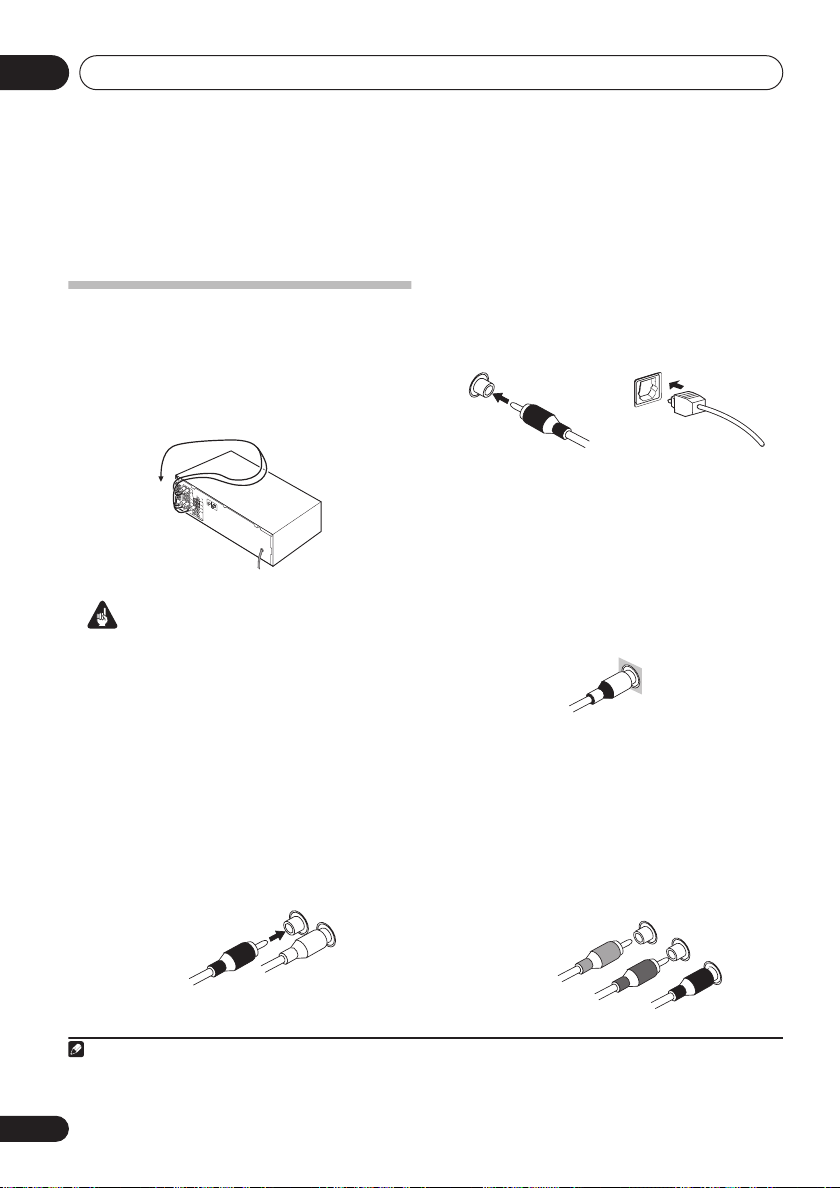
Digital audio cables
Commercially available coaxial digital audio
cables or optical cables should be used to
connect digital components to this receiver.
1
Coaxial digital audio cable Optical cable
Video cables
Standard RCA video cables
These cables are the most common type of
video connection and should be used to
connect to the composite video terminals. They
Important
• Before making or changing any
connections, switch off the power and
disconnect the power cord from the AC
outlet.
Analog audio cables
Use stereo RCA phono cables to connect
analog audio components. These cables are
typically red and white, and you should
connect the red plugs to R (right) terminals
and white plugs to L (left) terminals.
Analog audio cables
Right (red)
Left (white)
Note
1• When connecting optical cables, be careful when inserting the plug not to damage the shutter protecting the optical socket.
• When storing optical cable, coil loosely. The cable may be damaged if bent around sharp corners.
• You can also use a standard RCA video cable for coaxial digital connections.
have yellow plugs to distinguish them from
cables for audio.
tandard RCA video cable
Component video cables
(VSX-515 only)
Use component video cables to get the best
possible color reproduction of your video
source. The color signal of the TV is divided into
the luminance (
Y
) signal and the color (
PB and
PR) signals and then output. In this way,
interference between the signals is avoided.
Component video cables
Green (Y)
Blue (P
B
)
R
)
Red (P
12
En

Connecting up
Connecting a DVD player and TV
This page shows you how to connect your DVD
player and TV to the receiver.
1 Connect a coaxial digital audio output on
your DVD player to the DIGITAL COAX 1
(DVD/LD) input on this receiver.
Use a coaxial digital audio cable for the
connection.
2 Connect the composite video output and
the stereo analog audio outputs
DVD player to the DVD/LD inputs on this
receiver.
Use a standard RCA video cable3 and a stereo
RCA phono cable for the connection.
• If your DVD player has multichannel
analog outputs, see
multichannel analog outputs
to connect it.
3 Connect the analog audio outputs from
your TV to the TV/SAT inputs on this receiver.
This will allow you to play the sound from the
TV’s built-in tuner. Use a stereo RCA phono
cable to do this.
• If your TV has a built-in digital decoder, you
can also connect an optical digital audio
output from your TV to the
(TV/SAT)
optical cable for the connection.
4 Connect the MONITOR OUT video jack on
this receiver to a video input on your TV.
Use a standard RCA video cable to connect to
the composite video jack.
1
2
on your
Connecting the
below for how
DIGITAL OPT 1
input on this receiver. Use an
4
* The illustration shows the VSX-515, but
connections for the VSX-415 are the same.
DIGITAL
AUDIO OUT
OPTICAL
(TV/SAT)
ASSIGNABLE
DIGITAL IN
This receiver*
1
COAXIAL
DIGITAL OUT
DVD player
COAX
COAX
OPT
1
2
(CD)
1
(DVD
/LD)
R
IN
OUT
IN
IN
IN
OUT
IN
4
ANALOG AUDIO OUT
L
AUDIO
CD
DVR/
VCR
TV /
SAT
DVD
/LD
FRONT
REC
CD-R
/ TAPE
/ MD
PLAY
ANALOG OUT
TV
LR
FM UNBAL
75
Ω
VIDEO
IN
OUT
IN
MONITOR
D V D
5.1CH
INPUT
OUT
SUB
WOOFER
IN
PREOUT
2
AUDIORL
LOOP
AM
VIDEO IN
ANTENNA
VIDEO OUT
03
English
Deutsch
3
Français
Italiano
Nederlands
Español
Note
1 If your DVD player only has an optical digital output, you can connect it to the optical input on this receiver using an optical
cable. When you set up the receiver you’ll need to tell the receiver which input you connected the player to (for the VSX-415 see
Digital input settings
2 This connection will allow you to make analog recordings from your DVD player.
3
VSX-515 model only
video jacks
VSX-515 model only
4
nect this receiver to your TV.
on page 40 and for the VSX-515 see
– If your player also has a component video output, you can connect this too. See
on page 16 for more on this.
– See
Using the component video jacks
The Input Assign menu
on page 16 if you want to use the component video outputs to con-
on page 44).
Using the component
13
En

Connecting up03
Connecting the multichannel analog
outputs
For DVD Audio and SACD playback, your DVD
player may have 5.1 channel analog outputs.In
this case, you can connect them to the multi-
channel
inputs of the receiver as shown below.
This receiver*
CEN-
SUB
TER
R
L
AUDIO
CD
IN
DVR/
OUT
VCR
IN
OPT
1
TV/
(TV/SAT)
ASSIGNABLE
DIGITAL IN
SAT
IN
DVD
/LD
FRONT
IN
COAX
2
REC
(CD)
CD-R
OUT
/ TAPE
COAX
/ MD
1
(DVD
IN
PLAY
/LD)
RL RL
CENTER
OUTPUT
FRONT
OUTPUT
FM UNBAL
AM
75
Ω
LOOP
VIDEO
IN
OUT
IN
MONITOR
OUT
D V D
5.1CH
SUB
INPUT
WOOFER
IN
PREOUT
SURROUND
OUTPUT
ANTENNA
SURROUND
DVD 5.1CH INPUT
S
P
E
A
K
E
R
S
SUB
WOOFER
OUTPUT
WOOFER
LR
FRONT
RL
VIDEO
OUTPUT
DVD/multi-channel decoder
with multi-channel analog
output jacks
* The illustration shows the VSX-515, but
connections for the VSX-415 are the same.
COMPONENT VIDEO
YP
BPR
MONITOR OUT
CENT
1
1 Connect a set of audio/video outputs on
the set-top box component to the TV/SAT
AUDIO and VIDEO inputs on this receiver.
2
Use a stereo RCA phono cable for the audio
connection and a standard RCA video cable for
the video connection.
3
2 Connect an optical digital audio output
from your set-top box component to the
DIGITAL OPT 1 (TV/SAT) input on this receiver.
Use an optical cable for the connection.
4
This receiver*
R
L
(TV/SAT)
ASSIGNABLE
DIGITAL IN
COAX
COAX
OPT
1
2
(CD)
1
(DVD
/LD)
AUDIO
IN
OUT
IN
IN
IN
OUT
IN
/ TAPE
CD
DVR/
VCR
TV /
SAT
DVD
/LD
FRONT
REC
CD-R
/ MD
PLAY
D V D
5.1CH
INPUT
FM UNBAL
AM
Ω
75
LOOP
ANTENNA
VIDEO
IN
OUT
IN
MONITOR
OUT
SUB
WOOFER
IN
PREOUT
2 1
DIGITAL OUT
L
OPTICAL COAXIAL
VIDEOAUDIOR
AV OUT
Connecting a satellite receiver
or other digital set-top box
Satellite and cable receivers, and terrestrial
digital TV tuners are all examples of so-called
`set-top boxes’.
Note
1 The multichannel input can only be used when
2 If you’ve already connected your TV to the
which input you connected the set-top box to (for the VSX-415 see
Input Assign menu
3
VSX-515 model only
4 If your set-top box doesn’t have a digital audio output, omit this step. If it only has a coaxial digital output, you can connect it
to one of the coaxial inputs on this receiver, but you’ll need to tell the receiver which input you connected the set-top box to (for
the VSX-415 see
on page 44).
– See
Using the component video jacks
Digital input settings
on page 40 and for the VSX-515 see
DVD 5.1 ch
TV/SAT
inputs, simply choose another input. However, you’ll need to tell the receiver
* The illustration shows the VSX-515, but
connections for the VSX-415 are the same.
is selected (see page 36).
Digital input settings
on page 16 if your set-top box also has a component video output.
14
En
STB
on page 40 and for the VSX-515 see
The Input Assign menu
on page 44).
The

Connecting up
03
Connecting other audio
components
The number and kind of connections depends
on the kind of component you’re connecting.
Follow the steps below to connect a CD-R, MD,
DAT, tape recorder or other audio component.
1 If your component has a digital output,
connect this to a digital input on the receiver
as shown.
The example shows a coaxial connection to the
CD
digital input jack using a coaxial digital
audio cable.
2 If necessary, connect the analog audio
outputs of the component to a set of spare
audio inputs on this receiver.
You’ll need to make this connection for
components without a digital output, or if you
want to record from a digital component. Use a
stereo RCA phono cable as shown.
3 If you’re connecting a recorder, connect
the analog audio outputs (REC) to the analog
audio inputs on the recorder.
The example shows an analog connection to
the
CD-R/TAPE/MD
analog output jack using
a stereo RCA phono cable.
1
This receiver*
R
L
(TV/SAT)
ASSIGNABLE
DIGITAL IN
1
OPTICAL COAXIAL
DIGITAL OUT
OPT
1
COAX
2
(CD)
COAX
1
(DVD
/LD)
AUDIO
IN
OUT
IN
IN
IN
OUT
IN
2 3
CD
DVR/
VCR
TV /
SAT
DVD
/LD
FRONT
REC
CD-R
/ TAPE
/ MD
PLAY
R
AUDIO OUT
FM UNBAL
AM
Ω
75
LOOP
VIDEO
IN
IN
D V D
5.1CH
INPUT
IN
OUT
PLAY
OUT
MONITOR
OUT
SUB
WOOFER
PREOUT
L
R
AUDIO IN
CD-R, MD, DAT, Tape recorder, etc.
* The illustration shows the VSX-515, but
connections for the VSX-415 are the same.
ANTENNA
IN
REC
English
Deutsch
Français
Italiano
L
Nederlands
Español
About the WMA9 Pro decoder
VSX-515 model only
This unit has an on-board Windows Media®
Audio 9 Professional (WMA9 Pro) decoder, so
it is possible to playback WMA9 Pro-encoded
audio using a coaxial or optical digital
connection when connected to a WMA9 Pro-
Note
1 Note that you must connect digital components to analog audio jacks if you want to record to/from digital components (like
an MD) to/from analog components.
15
En

Connecting up03
compatible player. However, the connected
PC, DVD player, set-top box, etc. must be able
to output WMA9 Pro format audio signals
through a coaxial or optical digital output.
Microsoft, Windows Media®, and the Windows
logo are trademarks, or registered trademarks of
Microsoft Corporation in the United States and/
or other countries.
Connecting other video
components
This receiver has audio/video inputs and
outputs suitable for connecting analog or
digital video recorders, including VCRs, DVDrecorders and HDD recorders.
1 Connect a set of audio/video outputs on
the recorder to the DVR/VCR AUDIO and
VIDEO inputs on this receiver.
Use a stereo RCA phono cable for the audio
connection and a standard RCA video or Svideo cable for the video connection.
2 Connect a set of audio/video inputs on
the recorder to the DVR/VCR AUDIO and
VIDEO outputs on this receiver.
Use a stereo RCA phono cable for the audio
connection and a standard RCA video or Svideo cable for the video connection.
3 If your video component has a digital
audio output, connect it to a digital input on
this receiver.
The example shows a recorder connected to
the
DIGITAL COAX 1 (DVD/LD)
input.
1
This receiver*
R
L
(TV/SAT)
ASSIGNABLE
DIGITAL IN
3
OPTICAL COAXIAL
DIGITAL OUT
AUDIO
IN
OUT
IN
OPT
1
IN
IN
COAX
2
(CD)
OUT
COAX
1
(DVD
IN
/LD)
1 2
OUT
R L
AUDIO OUT
FM UNBAL
AM
75
Ω
LOOP
VIDEO
OUT
MONITOR
OUT
SUB
WOOFER
PREOUT
R L
AUDIO IN
ANTENNA
IN
REC
VIDEO IN
CD
DVR/
VCR
IN
TV /
SAT
IN
DVD
/LD
FRONT
D V D
5.1CH
INPUT
REC
IN
CD-R
/ TAPE
/ MD
PLAY
PLAY
VIDEO OUT
VCR, DVR, LD player, etc.
* The illustration shows the VSX-515, but
connections for the VSX-415 are the same.
Using the component video jacks
VSX-515 model only
Component video should deliver superior
picture quality when compared to composite
video. A further advantage (if your source and
TV are both compatible) is progressive-scan
video, which delivers a very stable, flicker-free
picture. See the manuals that came with your
TV and source component to check whether
they are compatible with progressive-scan
video.
Note
1 If your video component doesn’t have a digital audio output, omit this step. If it only has an optical digital output, you can connect it to the optical input on this receiver using an optical cable. When you set up the receiver you’ll need to tell the receiver
which input you connected the component to (for the VSX-415 see
Input Assign menu
on page 44).
Digital input settings
on page 40 and for the VSX-515 see
16
En
The

Connecting up
03
Important
• If you connect any source component to
the receiver using a component video
input, you must also have your TV
connected to this receiver’s
VIDEO MONITOR OUT
1 Connect the component video outputs of
your source to a set of component video
inputs on this receiver.
Use a three-way component video cable for the
connection.
2 If necessary, assign the component video
inputs to the input source you’ve connected.
This only needs to be done if you didn’t connect
according to the following defaults:
•
COMP 1
•
COMP 2
See
Assigning the component video inputs
page 44).
3 Connect the COMPONENT VIDEO
MONITOR OUT jacks on this receiver to the
component video inputs on your TV or
monitor.
Use a three-way component video cable.
–
–
DVD
TV
COMPONENT
jacks.
on
English
Deutsch
Français
Italiano
Nederlands
Español
17
En

Connecting up03
Connecting antennas
Connect the AM loop antenna and the FM wire
antenna as shown below. To improve reception
and sound quality, connect external antennas
(see
Using external antennas
make sure that the receiver is switched off and
unplugged from the wall outlet before making
or changing any connections.
below). Always
Antenna snap connectors
Twist the exposed wire strands together and
insert into the hole, then snap the connector
shut.
3
/8 in. (10mm)
AM loo
FM wire
antenna
CEN-
SUB
TER
ANTENNA
WOOFER
SURROUND
DVD 5.1CH INPUT
S
P
E
A
K
E
R
S
LR
R
(TV/SAT)
ASSIGNABLE
DIGITAL IN
R
L
AUDIO
FM UNBAL
AM
Ω
75
CD
IN
DVR/
OUT
VCR
IN
OPT
1
TV/
SAT
IN
DVD
/LD
FRONT
IN
COAX
2
REC
(CD)
CD-R
OUT
/ TAPE
COAX
/ MD
1
(DVD
IN
PLAY
/LD)
LOOP
VIDEO
IN
OUT
IN
MONITOR
OUT
D V D
5.1CH
SUB
INPUT
WOOFER
IN
PREOUT
FM wire antenna
Connect the FM wire antenna and fully extend
vertically along a window frame or another
suitable place that gives good reception.
AM loop antenna
Assemble the antenna and connect to the
receiver. Attach (if necessary) and face in the
direction that gives the best reception.
Using external antennas
To improve FM reception
Use an F connector to connect an external FM
antenna.
F connector
To improve AM reception
Connect a 15–18 foot length of vinyl-coated
wire to the AM antenna terminal without
disconnecting the supplied AM loop antenna.
For the best possible reception, suspend
horizontally outdoors.
Outdoor
antenna
15–18 ft. (5–6m)
FM UNBAL
AM
75
Ω
LOOP
ANTENNA
Indoor antenna
(vinyl-coated wire)
18
En
FM UNBAL
AM
75
Ω
LOOP
ANTENNA

Connecting up
Connecting the speakers (VSX-415)
A complete setup of six speakers (including the subwoofer) is shown below, but everyone’s home
setup will vary. Simply connect the speakers you have in the manner shown below. The receiver
will work with just two stereo speakers (the front speakers in the diagram) but using at least three
speakers is recommended, and a complete setup is best. If you’re not using a subwoofer, change
the front speaker setting (see
Make sure you connect the speaker on the right to the right terminal and the speaker on the left
to the left terminal. Also make sure the positive and negative (
those on the speakers. You can use speakers with a nominal impedance between 6–16
see
Switching the speaker impedance
less than 8
Ω
).
Be sure to complete all connections before connecting this unit to the AC power source.
Speaker setting
on page 38) to large.
+/–
) terminals on the receiver match
on page 51 if you plan to use speakers with an impedance of
Ω
(please
03
English
Deutsch
Français
Front speakers
Surround speakersCenter speaker
LR C LSRS
CEN-
SUB WOOFER
R
L
AUDIO
FM UNBAL
Ω
75
CD
IN
DVR/
OUT
DIGITAL IN
ASSIGNABLE
VCR
IN
OPT
1
(TV/
IN
SAT)
COAX
2
IN
(CD)
COAX
1
OUT
(DVD
/LD)
IN
VIDEO
IN
TV/
SAT
DVD
/LD
FRONT
CD-R
/ TAPE
PLAY
OUT
IN
MONITOR
OUT
D V D
5.1CH
SUB
INPUT
REC
WOOFER
IN
PREOUT
/ MD
Powered subwoofer
SW
INPUT
1 Twist exposed wire strands together.
2 Unclip speaker terminal and insert wire.
TER
AM
LOOP
ANTENNA
SURROUND
DVD 5.1CH INPUT
LR
CENTER
FRONT
SPEAKER
SPEAKER
RL RL
SURROUND
SPEAKERS
12 3
ª
10mm
·
• The speaker terminals also accept single
banana plugs.
3 Snap shut the speaker terminal to secure.
SURROUND
PREOUT
Italiano
Nederlands
VSX-415
The SURROUND
PREOUT
terminal is
intended for use
with a wireless
L
AC OUTLET
R
speaker system.
See your
wireless speaker
manual for more
details on
connecting up.
or
ª
·
ª
·
Español
19
En

Connecting up03
Connecting the speakers (VSX-515)
A complete setup of eight speakers (including the subwoofer) is shown below, but everyone’s
home setup will vary. Simply connect the speakers you have in the manner shown below. The
receiver will work with just two stereo speakers (the front speakers in the diagram) but using at
least three speakers is recommended, and a complete setup is best for surround sound. If you’re
not using a subwoofer, change the front speaker setting (see
Make sure you connect the speaker on the right to the right terminal and the speaker on the left
to the left terminal. Also make sure the positive and negative (
those on the speakers.
see
Switching the speaker impedance
less than 8
Ω
).
1
You can use speakers with a nominal impedance between 6–16Ω (please
on page 51 if you plan to use speakers with an impedance of
Be sure to complete all connections before connecting this unit to the AC power source.
Front speakers
LR C LSRS
R
L
AUDIO
CD
IN
DVR/
OUT
VCR
IN
OPT
(TV/SAT)
ASSIGNABLE
DIGITAL IN
1
COAX
2
(CD)
COAX
1
(DVD
/LD)
IN
TV/
SAT
IN
IN
DVD
/LD
FRONT
IN
D V D
5.1CH
INPUT
REC
IN
CD-R
OUT
/ TAPE
/ MD
IN
PLAY
FM UNBAL
AM
75
Ω
LOOP
VIDEO
OUT
MONITOR
OUT
SUB
WOOFER
PREOUT
Center speaker
CEN-
SUB
TER
WOOFER
ANTENNA
LR
SURROUND
DVD 5.1CH INPUT
FRONT
RL R L
S
P
E
A
K
E
R
S
COMPONENT VIDEO
YP
MONITOR OUT
Surround speakers
(
)
ASSIGNABLE
DVD/ LD
IN
¥
YPBP
BPR
R
(
)
TV / SAT
IN
ø
CENTER SURROUND
SURROUND BACK
RL
SINGLE
SEE INSTRUCTION
MANUAL
Speaker setting
+/–
) terminals on the receiver match
Surround back speakers
SBL SBR
AC OUTLET
on page 42) to large.
VSX-515
Powered subwoofer
SW
1 Twist exposed wire strands together.
2 Loosen terminal and insert exposed wire.
INPUT
Single
surround
back
speaker
12 3
10mm
or
• The speaker terminals also accept single
banana plugs.
3 Tighten terminal.
Note
1 If you are using only one surround back speaker, connect the positive wire to the right channel (+) terminal, and the negative
wire to the left channel (
–
) terminal (see illustration).
20
En

Connecting up
03
Speaker terminals
Make sure that all the bare speaker wire is
twisted together and inserted fully into the
speaker terminal. If any of the bare speaker
wire is touching the back panel when you
switch the unit on, the power may cut off as a
safety measure. Use good quality speaker wire
to connect the speakers to the receiver.
Caution
• These speaker terminals are hazardous
when live. To prevent the risk of electric
shock when connecting or disconnecting
the speaker cables, disconnect the power
cord.
Hints on speaker placement
Speakers are usually designed with a
particular placement in mind. Some are
designed to be floorstanding, while others
should be placed on stands to sound their best.
Some should be placed near a wall; others
should be placed away from walls. We have
provided a few tips on getting the best sound
from your speakers (following), but you should
also follow the guidelines on placement that
the speaker manufacturer provided with your
particular speakers to get the most out of
them.
• Place the front left and right speakers at
equal distances from the TV.
• When placing speakers near the TV, we
recommend using magnetically shielded
speakers to prevent possible interference,
such as discoloration of the picture when
the TV is switched on. If you do not have
magnetically shielded speakers and notice
discoloration of the TV picture, move the
speakers farther away from the TV.
• Place the center speaker above or below
the TV so that the sound of the center
channel is localized at the TV screen.
• If possible, place the surround speakers
slightly above ear level.
• Try not to place the surround speakers
further away from the listening position
than the front and center speakers. Doing
so can weaken the surround sound effect.
• To achieve the best possible surround
sound, install your speakers as shown
below. Be sure all speakers are installed
securely to prevent accidents and improve
sound quality.
Caution
• If you choose to install the center speaker
on top of the TV, be sure to secure it with
putty, or by other suitable means, to reduce
the risk of damage or injury resulting from
the speaker falling from the TV in the event
of external shocks such as earthquakes.
• Make sure no exposed speaker wire is
touching the rear panel, this may cause the
receiver to turn off automatically.
Speaker placement diagrams
The following illustrations show 6.1 and 7.1
channel speaker setups.
3-D view of
6.1 channel
1
speaker setup
English
Deutsch
Français
Italiano
Nederlands
Español
Note
1
VSX-415 model only
– Follow the speaker placement diagrams, disregarding the surround back speakers.
21
En

Connecting up03
3-D view of
7.1 channel
speaker setup
Overhead view of speaker setup
Front
left
Surround
left
Listening position
Surround back Surround back
left right
Single surround back speaker
Front
rightCenter
Subwoofer
Surround
right
Extra Power mode speaker setup
VSX-415 only –
surround effects
Extra Power mode (
see
Using the Advanced
on page 30 to switch on the
EX POWER
).
AC outlet
Power supplied through this outlet is turned on
and off by the receiver’s power switch. Total
electrical power consumption of connected
equipment should not exceed 100 W (0.8 A).
• This unit should be disconnected by
removing the power plug from the wall
socket when not in regular use (ex. when
on vacation).
AC OUTLET
Caution
•
Do not connect a TV set
similar appliance to this unit’s AC outlet.
• Do not connect appliances with high
power consumption to the AC outlet in
order to avoid overheating and fire risk.
This can also cause the receiver to
malfunction.
• Since a subwoofer or power amplifier can
exceed the 100W maximum when playing
sources at a high volume, this type of
equipment should not be connected to the
AC outlet.
, monitor, heater, or
22
En
Front left
Surround
left
Center
Subwoofer
Listening position
Front right
Surround
right
.

Controls and displays
04
Chapter 4:
Controls and displays
Front panel
8
ADVANCED
SURR
LISTENING MODE
ST/DIRECT
/AUTO SURR
STANDARD
VSX-515 model
16
– STATION + – TUNING +
VSX-415 model
9
SIGNAL
SELECT
STANDBY/ON
PHONES
65
13 1410 11 12
FL DIMMER
INPUT
ATT
SPEAKER
IMPEDANCE
EXTENDED
MODE
18
TUNING
TUNER
CLASS
/STATION
TONE
EDIT
MULTI JOG
VSX-515 model VSX-415 model
1
DVD/LD DVD 5.1 TV/SAT DVR/VCR
MUTE
1915 16 17 20
QUICK
SYSTEM
SETUP
RETURN
SETUP
CD
CD-R/TAPE/MD
8
ADVANCED
SURROUND
LISTENING MODE
STEREO/
DIRECT
STANDARD
12 14 10 11 17 18 19
SPEAKER
IMPEDANCE
English
Deutsch
2
FM
SIGNAL
SELECT
INPUT
ATT
9
3 4
AUDIO/VIDEO MULTI-CHANNEL RECEIVER
ENTER
AM
7
21
VSB
MODE
TUNER
EDIT
TONEMUTE FL DIMMER
MULTI JOG
MULTI JOG
QUICK
SETUP
Français
MASTER
VOLUME
UPDOWN
Italiano
Nederlands
Español
1 Input select buttons
Press to select an input source.
2 Character display
See
Display
on page 25.
3
ENTER
4
MULTI JOG
The
MULTI JOG
dial
dial performs a number of
tasks. Use it to select options after pressing the
designated
5
MULTI JOG
STANDBY/ON
buttons.
Switches the receiver between on and standby.
6
PHONES
jack
Use to connect headphones. When the
headphones are connected, there is no sound
output from the speakers.
7
MASTER VOLUME
8
LISTENING MODE
buttons
STANDARD
Press for Standard decoding and to switch
between the various Pro Logic II and Neo:6
options (page 29).
23
En

Controls and displays04
ADVANCED SURROUND
Use to switch between the various
surround modes
STEREO/DIRECT (AUTO SURR)
Switches between direct and stereo
playback. Direct playback bypasses the
tone controls and channel levels for the
most accurate reproduction of a source
(page 32).
VSX-515 model only
Surround mode (
9 SIGNAL SELECT
Use to select an input signal (page 32).
10
FL DIMMER
Dims or brightens the display.
11
INPUT ATT
Attenuates (lowers) the level of an analog input
signal to prevent distortion.
12
SPEAKER IMPEDANCE
Use to change the impedance setting
(page 51)
13
EXTENDED MODE
VSX-515 model only
Selects a surround back channel option
(page 33) or (when the surround back speakers
are not available) the Virtual Surround Back
(VSB) mode (page 34).
14
MUTE
Mutes the sound (or restores the sound if it has
been muted).
15
CLASS
VSX-515 model only
Switches between the three banks (classes) of
station presets
16
TUNING / STATION
Selects the frequency (page 46) and station
presets (page 47) when using the tuner.
17
TUNER EDIT
Press to memorize and name a station for
recall
(page 46).
(page 30).
– Selects the Auto
Important
(page 46).
on page 29).
buttons
18
TONE
Press this button to access the bass and treble
controls, which you can then adjust with the
MULTI JOG
19
QUICK SETUP
See
20 System Setup menu controls
VSX-515 model only
SYSTEM SETUP
Use with the
System Setup menu (page 41).
RETURN
Press to confirm and exit the current menu
screen.
21
VSB MODE
VSX-415 model only
Selects the Virtual Surround Back (VSB) mode
(page 34).
dial (page 35).
Using the Quick Setup
MULTI JOG
on page 10.
dial to access the
24
En

Controls and displays
Display
VSX-515 model:
1234567118910
04
English
Deutsch
SP
A
Français
12
13 19 20
VSX-415 model:
1234569811
12
1
SIGNAL SELECT
Lights to indicate the type of input signal
assigned for the current component:
AUTO
Lights when
SB
Depending on the source, this lights when
a signal with surround back channel
encoding is detected.
DIGITAL
Lights when a digital audio signal is
detected.
indicators
AUTO
signal select is on.
14
14 16
2
When the
on, this lights to indicate decoding of a DTS
multichannel signal.
16 1715 18
10
2
DIGITAL
Lights when a Dolby Digital encoded signal
is detected.
ANALOG
Lights when an analog signal is detected.
DTS
Lights when a source with DTS encoded
audio signals is detected.
STANDARD
1918
mode of the receiver is
Italiano
Nederlands
Español
25
En

Controls and displays04
3
2
DIGITAL
When the
on, this lights to indicate decoding of a Dolby
Digital multichannel signal.
4
2
PRO LOGIC II
When the (
the receiver is on,
indicate Pro Logic II decoding.
VSX-515 model only – 2 PRO LOGIC II x lights
to indicate Pro Logic IIx decoding (see
Listening in surround sound
5 VIR.SB
Lights during Virtual surround back
processing (page 34).
6
DIRECT
Lights when source direct playback is in use.
Direct playback bypasses the tone controls
and channel levels for the most accurate
reproduction of a source.
7 AUTO SURR.
Lights when the Auto Surround feature is
switched on (see
8
ATT
Lights when
(reduce) the level of the analog input signal.
9 SLEEP
Lights when the receiver is in sleep mode
(page 36).
10
Tuner
/
Lights when the mono mode is set using
the
MPX
/ STEREO
Lights when a stereo FM broadcast is being
received in auto stereo mode.
/
Lights when a broadcast is being received.
STANDARD
STANDARD
INPUT ATT
indicators
MONO
button.
TUNED
mode of the receiver is
x
) Pro Logic II mode of
2
PRO LOGIC II
on page 29 for
(VSX-515 model only)
Important
on page 29).
is used to attenuate
lights to
11 Speaker indicator
Shows if the speaker system is on or not. SPA
means the speakers are switched on.
means the headphones are connected.
12 Character display
13
Neo:6 (VSX-515 model only)
When the (
receiver is on, this lights to indicate Neo:6
processing.
14
Lights when one of the Advanced Surround
modes has been selected.
15 WMA9 Pro (VSX-515 model only)
Lights to indicate decoding of a WMA9 Pro
signal.
16 MIDNIGHT
Lights during Midnight listening (page 35).
17 D.E. (VSX-515 model only)
Lights when Dialog Enhancement (
is switched on (page 35).
18
Lights during Loudness listening (page 35).
19 EX
Lights when a Dolby Digital Surround EX
encoded signal is detected.
20 Master volume level
Shows the overall volume level. —dB indicates
the minimum level, and — 0 dB indicates the
maximum level.
Depending on your level settings for each
channel, the maximum volume can range
between –10 dB and –0 dB.
STANDARD
ADV.SURR.
LOUDNESS
) Neo:6 mode of the
(Advanced Surround)
SP
DIALOG E
)
26
En

Controls and displays
04
Remote control
Illustration shows the VSX-515 remote control
RECEIVER
SLEEP
FL DIMMER
1
2
3
4
5
1
RECEIVER
INPUT SELECTOR
DVD 5.1CH
DVD/LD
CD-R/
TAPE/MD
CD FM AM
ADVANCED
SURROUND
STANDARD
TOP MENU
SYSTEM
SETUP
DVD
RECEIVER CONTROL
EFFECT/CH SEL
SIGNAL
DIALOG E
SELECT
DVD
TUNING STATION
AUDIO
SUB TITLE
RECEIVER
TV/SAT DVR/VCR
STEREO
ENTER
VOLUME
LEVEL
TUNER
EDIT
TUNER
DVD CONTROL
INPUT ATT
MIDNIGHT/
LOUDNESS
MENU
RETURN
RECEIVER
MUTE
CLASS
MPX
DISPLAY
Switches the receiver between standby and on.
2
Listening mode
buttons
STANDARD
Press for Standard decoding and to switch
between the various Pro Logic II and Neo:6
options (page 29).
ADVANCED SURROUND
Use to switch between the various
surround modes
(page 30).
6
7
8
9
10
11
12
STEREO
Switches between direct and stereo
playback. Direct playback bypasses the
tone controls and channel levels for the
most accurate reproduction of a source
(page 32).
VSX-515 model only
Surround mode(
– Selects the Auto
Important
on page 29).
MIDNIGHT/LOUDNESS
Switches to Midnight or Loudness
listening
3
TOP MENU
(page 35).
Displays the disc ‘top’ menu of a DVD.
SYSTEM SETUP
(VSX-515 model only)
Press to access the System Setup menu
(page 41).
TUNER EDIT
(VSX-415 model only)
Press to memorize and name a station for
recall
(page 46).
4 DVD
Press to use the DVD controls on the remote.
5
RECEIVER CONTROL
buttons
VOLUME +/–
Use to set the listening volume.
MUTE
Mutes/unmutes the sound.
VSX-515 model only:
EFFECT/CH SEL
Press repeatedly to select a channel, then
use
LEVEL +/–
to adjust the level (page 43).
Also adjusts the level of the Advanced
Surround effects (page 30) as well as Dolby
Pro Logic IIx Music (page 31) and Neo:6
Music parameters (page 32). You can then
use the
LEVEL +/–
buttons to make these
adjustments.
LEVEL +/–
Use to adjust the effect and channel levels,
as well as to change Dolby Pro Logic IIx
and Neo:6 Music parameter settings.
English
Deutsch
Français
Italiano
Nederlands
Español
27
En

Controls and displays04
DIALOG E
Use to make dialog stand out when
watching TV or a movie (page 35).
SIGNAL SELECT
Use to select an input signal (page 32).
TUNER EDIT
Press to memorize and name a station for
recall
(page 46).
VSX-415 model only:
CH SELECT
Selects a speaker when setting up the
surround sound of the receiver
(page 40).
TEST TONE
Sounds the test tone when setting up the
surround sound of the receiver
(page 40).
LEVEL +/–
Adjusts the channel levels (page 40).
EFFECT +/–
Adds or subtracts the amount of effect with
the advanced surround modes (page 30).
6
SLEEP
Use to set the sleep timer (page 36).
FL DIMMER
Dims or brightens the display.
INPUT ATT
Attenuates (lowers) the level of an analog
input signal to prevent distortion.
7 INPUT SELECTOR buttons
Press to select an input source.
8
MENU
Displays the disc menu of DVD-Video
discs. It also displays TV menus.
RETURN
(VSX-515 model only)
Confirm and exit the current menu screen.
9
/ENTER
Use the arrow buttons when setting up your
surround sound system (
VSX-515 –
page 41). Also used for DVD menus.
VSX-415 –
page 37,
10 RECEIVER
Use to switch to the receiver controls on the
remote control. Also used when setting up the
surround sound for the receiver (
page 37,
VSX-515 –
page 41).
VSX-415 –
11 TUNER controls
The
TUNING +/–
radio frequencies (page 46) and the
+/–
buttons can be used to select preset radio
buttons can be used to find
STATION
stations (page 47).
CLASS
Switches between the three banks
(classes) of station presets
(page 46).
MPX
Use to switch between auto stereo and
mono reception of FM broadcasts. If the
signal is weak then switching to mono will
improve the sound quality (page 46).
DISPLAY
Switch the display between station preset
name and frequency (see tip on page 47).
12 DVD CONTROL buttons
You can use these buttons to control a Pioneer
DVD player connected to your system.
Button
DVD
AUDIO
SUBTITLE
What it does
Turns DVD power on/off.
Changes the audio language or
channel.
Displays/changes the subtitles on
multilingual DVD-Video discs.
Starts/resumes normal playback.
Pauses/unpauses a disc.
Stops playback.
Press to start fast reverse scanning.
Press to start fast forward scanning.
Skips to the start of the current track or
chapter, then previous tracks/chapters.
Skips to the next track or chapter.
28
En

Listening to your system
INPUT SELECTOR
RECEIVER
CD-R/
TAPE/MD
MIDNIGHT/
LOUDNESS
ADVANCED
SURROUND
STANDARD STEREO
SLEEP
DVD/LD
CD FM AM
TV/SAT DVR/VCR
DVD 5.1CH
FL DIMMER
INPUT ATT
05
Chapter 5:
Listening to your system
Important
• Certain features explained in this section
will not be possible depending on the
source (for example, PCM 88.2 / 96kHz,
DTS 96kHz (24 bit) or WMA 9 Pro sources).
Auto playback
VSX-515 model only
There are many ways to listen back to sources
using this receiver, but for the simplest, most
direct listening option is the Auto Surround
feature. With this, the receiver automatically
detects what kind of source you’re playing and
selects multichannel or stereo playback as
necessary.
• While listening to a source, press
STEREO for auto playback of a source.
Press repeatedly until
briefly in the display (it will then show the
decoding or playback format). Check the
digital format indicators in the display to see
how the source is being processed.
1
RECEIVER
DVD/LD
STANDARD STEREO
SLEEP
FL DIMMER
INPUT ATT
INPUT SELECTOR
TV/SAT DVR/VCR
DVD 5.1CH
CD-R/
TAPE/MD
CD FM AM
MIDNIGHT/
ADVANCED
LOUDNESS
SURROUND
AUTO SURR.
shows
Listening in surround sound
Using this receiver, you can listen to any
source in surround sound. However, the
options available will depend on your speaker
setup and the type of source you’re listening to.
VSX-515 only
speakers, see also
channel (Extended mode)
• While listening to a source, press STANDARD.
If the source is Dolby Digital, DTS, or Dolby
Surround encoded, the proper decoding
format will automatically be selected and
shows in the display.
With two channel sources
repeatedly to select from:
2
•
sound, especially suited to movie sources
•
2
sound, especially suited to music sources
•
2
sound
– If you connected surround back
Using the surround back
on page 33.
2
, press
Pro Logic II MOVIE
Pro Logic II MUSIC
PRO LOGIC
– Up to 5.1 channel
– Up to 5.1 channel
– 5.1 channel surround
English
Deutsch
Français
Italiano
Nederlands
Español
STANDARD
Note
1• Stereo surround (matrix) formats are decoded accordingly using
in surround sound
• The Auto Surround feature is canceled if you connect headphones or select the multichannel analog inputs.
2
VSX-515 model only –
2 Pro Logic IIx
above for more on these decoding formats).
If the Extended mode (page 33) is switched to
becomes 2
Pro Logic II
(5.1 channel sound).
Neo:6 CINEMA
OFF
, or the surround back speakers are set to NO (page 42),
or 2
Pro Logic IIx MOVIE
(see
Listening
29
En

Listening to your system05
INPUT SELECTOR
RECEIVER
CD-R/
TAPE/MD
MIDNIGHT/
LOUDNESS
ADVANCED
SURROUND
STANDARD STEREO
SLEEP
DVD/LD
CD FM AM
TV/SAT DVR/VCR
DVD 5.1CH
FL DIMMER
INPUT ATT
VSX-515 model only:
•2 Pro Logic IIx MOVIE
– Up to 7.1
channel sound, especially suited to movie
sources
•
2
Pro Logic IIx MUSIC
– Up to 7.1
channel sound, especially suited to music
sources
•
2
Pro Logic IIx GAME
– Up to 7.1
channel sound, especially suited for video
games
•
2
PRO LOGIC
– 5.1 channel surround
sound
•
Neo:6 CINEMA
– 6.1 channel sound,
especially suited to movie sources
•
Neo:6 MUSIC
– 6.1 channel sound, espe-
cially suited to music sources
VSX-515 model only – With multichannel
sources, if you have connected surround back
speaker(s) and have selected
Extended ON1,
you can select (according to format):
•
2 Pro Logic IIx MUSIC
– See above (only
available when you’re using two surround
back speakers)
•
Dolby Digital EX
– Creates surround back
channel sound for 5.1 channel sources and
provides pure decoding for 6.1 channel
sources (like Dolby Digital Surround EX)
•
DTS-ES
– Allows you to hear 6.1 channel
playback with DTS encoded sources
Using the Advanced surround effects
The Advanced surround effects can be used for
a variety of additional surround sound effects.
Most Advanced Surround modes are designed
to be used with film soundtracks, but some
modes are also suited for music sources. Try
different settings with various soundtracks to
see which you like.
• Press ADVANCED SURROUND repeatedly
to select a listening mode.
•
ADV. MOVIE
ronment of a movie theater, and is suitable
for watching movies.
•
ADV. MUSIC
environment of a large concert hall and is
suitable for music or musical sources.
•
TV SURR.
sound for both mono and stereo TV
sources. It is useful for older movies
recorded with mono soundtracks.
•
SPORTS
programs with a lot of action, adding to the
excitement by bringing background action
to the forefront.
•
ADV. GAME
games. It works especially well with sound
moving from left to right in game software
with a lot of movement.
2
– Simulates the relaxed envi-
– Simulates the acoustic
– This mode produces surround
– This is designed for sports
– Useful when playing video
Note
1 During playback of a Dolby Digital multichannel source with the Extended mode switched ON, you will only be able to select
Dolby Digital EX
2• If you press
ically be selected.
• VSX-515 model only –
surround back speakers in your setup. For more on this, refer to
30
En
or 2 Pro Logic IIx MUSIC
ADVANCED SURROUND
Depending on the source and the sound mode you have selected, you may not get sound from the
. See
Using the surround back channel (Extended mode)
when the headphones are connected, the
Using the surround back channel (Extended mode)
PHONES SURROUND
on page 33 for more on this.
mode will automat-
on page 33.
Loading…
Register your product at:
www.pioneerelectronics.com
• Protect your new investment
The details of your purchase will be on file for reference in the event of an
insurance claim such as loss or theft.
• Improve product development
Your input helps us continue to design products that meet your needs.
• Receive a free Pioneer newsletter
Registered customers can opt in to receive a monthly newsletter.
• Receive free tips, updates and service bulletins on
your new product
AUDIO/VIDEO MULTI-CHANNEL
RECEIVER
RECEPTEUR AUDIOVISUEL A
VOIES MULTIPLES
VSX-415
VSX-515
Operating Instructions
Mode d’emploi
VSX_415-515.fm 1 ページ 2004年12月8日 水曜日 午後3時12分
|
Код: 46558 Извините, товара сейчас нет в наличии
Бесплатная доставка Извините, товара сейчас нет в наличии Сравнить Новости интернет-магазина «Лаукар»:23.04.2025 26.02.2025 17.02.2025 Дополнительная информация в категории Краскопульт:Таблица Авторизованных сервисных центров по брендам. Описание Инструкция Отзывы (0) В интернет-магазине бытовой техники «Лаукар» Вы можете скачать инструкцию к товару Краскопульт Bosch PFS 55 [0603206000] совершенно бесплатно. Все инструкции, представленные на сайте интернет-магазина бытовой техники «Лаукар», предоставляются производителем товара. Для того чтобы скачать инструкцию, Вам необходимо нажать на ссылку «скачать инструкцию», расположенную ниже, а в случае, если ссылки нет, Скачать инструкцию Смотреть инструкцию 
Фирма-производитель оставляет за собой право на внесение изменений в конструкцию, дизайн и комплектацию товара: Краскопульт Bosch PFS 55 [0603206000]. Пожалуйста, сверяйте информацию о товаре с информацией на |