
Operating Instructions
System Controller
Model No. WV-CU650
Before attempting to connect or operate this product,
please read these instructions carefully and save this manual for future use.
ENGLISH VERSION
Caution:
Before attempting to connect or operate this product,
please read the label on the bottom.
CAUTION
RISK OF ELECTRIC SHOCK
DO NOT OPEN
CAUTION: TO REDUCE THE RISK OF ELECTRIC SHOCK,
DO NOT REMOVE COVER (OR BACK).
NO USER-SERVICEABLE PARTS INSIDE.
REFER SERVICING TO QUALIFIED SERVICE PERSONNEL.
The lightning flash with arrowhead symbol,
within an equilateral triangle, is intended to
alert the user to the presence of uninsulated
«dangerous voltage» within the product’s
enclosure that may be of sufficient magni-
SA 1965
SA 1966
tude to constitute a risk of electric shock to
persons.
The exclamation point within an equilateral
triangle is intended to alert the user to the
presence of important operating and maintenance (servicing) instructions in the literature accompanying the appliance.
For U.S.A
NOTE: This equipment has been tested and found to comply with the limits for a Class A digital device, pursuant to
Part 15 of the FCC Rules. These limits are designed to provide reasonable protection against harmful interference
when the equipment is operated in a commercial environment. This equipment generates, uses, and can radiate
radio frequency energy and, if not installed and used in
accordance with the instruction manual, may cause harmful
interference to radio communications.
Operation of this equipment in a residential area is likely to
cause harmful interference in which case the user will be
required to correct the interference at his own expense.
FCC Caution: To assure continued compliance, (example use only shielded interface cables when connecting to computer or peripheral devices). Any changes or modifications
not expressly approved by the party responsible for compliance could void the user’s authority to operate this equipment.
The serial number of this product may be found on the bottom of the unit.
You should note the serial number of this unit in the space
provided and retain this book as a permanent record of your
purchase to aid identification in the event of theft.
Model No. WV-CU650
Serial No.
WARNING: To prevent fire or electric shock hazard, do not expose this appliance to rain or moisture. The apparatus shall not be exposed to
dripping or splashing and that no objects filled with liquids, such as vases, shall be placed on the apparatus.
2

IMPORTANT SAFETY INSTRUCTIONS
1) Read these instructions.
2) Keep these instructions.
3) Heed all warnings.
4) Follow all instructions.
5) Do not use this apparatus near water.
6) Clean only with dry cloth.
7) Do not block any ventilation openings. Install in accordance with the manufacturer’s instructions.
 Do not use near any heat sources such as radiators, heat registers, stoves, or other apparatus (including amplifiers) that
produce heat.
9) Do not defeat the safety purpose of the polarized or grounding-type plug. A polarized plug has two blades with one wider
than the other. A grounding-type plug has two blades and a third grounding prong. The wide blade or the third prong are
provided for your safety. If the provided plug does not fit into your outlet, consult an electrician for replacement of the
obsolete outlet.
10) Protect the power cord from being walked on or pinched particularly at plugs, convenience receptacles and the points
where they exit from the apparatus.
11) Only use attachments/accessories specified by the manufacturer.
12) Use only with the cart, stand, tripod, bracket, or table specified by the manufacturer, or sold with the apparatus. When a
cart is used, use caution when moving the cart/apparatus combination to avoid injury from tip-overs.
S3125A
13) Unplug this apparatus during lightning storms or when unused for long periods of time.
14) Refer all servicing to qualified service personnel. Servicing is required when the apparatus has been damaged in any way,
such as power-supply cord or plug is damaged, liquid has been spilled or objects fallen into the apparatus, the apparatus
has been exposed to rain or moisture, does not operate normally, or has been dropped.
3

CONTENTS
IMPORTANT SAFETY INSTRUCTIONS …………………………3
PREFACE ………………………………………………………………….5
FEATURES ………………………………………………………………..5
PRECAUTIONS ………………………………………………………….6
LIMITATION OF LIABILITY ………………………………………….6
DOCUMENT CONVENTION ………………………………………..7
NOTIFICATION ABOUT SYSTEM UNITS ……………………….7
MAJOR OPERATING CONTROLS
AND THEIR FUNCTIONS …………………………………………….8
■ Main Unit ……………………………………………………………8
■ 3D Joystick Unit ………………………………………………..12
■ LCD Display Descriptions …………………………………..13
INSTALLATIONS AND CONNECTIONS ………………………16
■ Basic System Connections …………………………………16
■ Connection with the 3D Joystick Unit ……………………17
■ Adjustment of 3D Joystick …………………………………..17
SETUP PROCEDURES (HARDWARE) …………………………18
■ Setup Procedures ……………………………………………..18
■ MODE Switch Setting …………………………………………18
■ CONTROLLER NO. Switch Setting ………………………18
SETUP PROCEDURES (FIRMWARE) ………………………….19
■ Administrator Password Entry ……………………………..19
■ Setting Modes …………………………………………………..19
■ All Reset …………………………………………………………..20
■ PS·Data Communication Setting ………………………….20
■ To Change the Administrator Password ……………….24
■ Database Copy …………………………………………………25
■ PS·Data Operator Password Check ……………………..26
BEFORE OPERATION ………………………………………………27
■ Power-on ………………………………………………………….27
■ Power-off ………………………………………………………….27
■ Basic Operation Flow …………………………………………28
■ LCD/BUZZER Adjustment …………………………………..28
■ Operation Start (Login) ……………………………………….29
■ If You Have Forgotten the Login Password ……………30
■ Operation Start (Auto Login) ……………………………….30
■ Operation End (Logout) ……………………………………..30
UNIT SELECTION …………………………………………………….31
■ System Unit Selection ………………………………………..31
■ Recorder Selection …………………………………………….31
■ Monitor Selection ……………………………………………….32
■ Camera Selection ………………………………………………32
SYSTEM UNIT CONTROL ………………………………………….33
■ Multiscreen Display ……………………………………………33
■ Electronic Zooming ……………………………………………33
■ Tour Sequence/Group Sequence ………………………..33
■ On-screen Display (OSD) Control ………………………..33
■ System Function Control …………………………………….34
RECORDER CONTROL …………………………………………….35
■ Manual Recording ……………………………………………..35
■ Playback …………………………………………………………..35
■ Search Playback ……………………………………………….35
■ Time & Date Search Playback …………………………….38
■ Other Available Functions …………………………………..39
CAMERA CONTROL …………………………………………………40
■ Camera Panning/Tilting Control …………………………..40
■ Zooming Control ………………………………………………..40
■ Lens Iris Control ………………………………………………..40
■ Lens Focus Control ……………………………………………40
■ Preset Position Control ……………………………………….41
■ Home Position Control ………………………………………..41
■ Camera Function Control ……………………………………41
■ Camera Position Control …………………………………….42
■ Camera Selection Recall …………………………………….42
■ Wiper Control ……………………………………………………42
■ Defroster Control ……………………………………………….43
■ Auxiliary Control ………………………………………………..43
■ Other Functions …………………………………………………43
ALARM CONTROL …………………………………………………..44
■ System Controller Behavior
during the Alarm Mode ………………………………………44
■ Alarm Reset ………………………………………………………44
■ Alarm Suspension ……………………………………………..44
■ Alarm History Search …………………………………………44
MENU FUNCTION DESCRIPTIONS ……………………………47
■ Menu Flow ………………………………………………………..47
■ Menu Function Categories ………………………………….48
■ To Recall Menu Functions …………………………………..51
■ Factory Default Setting of Button Functions
and Joystick Button Functions …………………………….52
■ To Assign Menu Functions to Function Buttons ……..52
■ To Assign Menu Functions
to Joystick Function Buttons ……………………………….53
■ To Recall Button Functions
and Joystick Button Functions …………………………….53
■ To Check Button Functions
and Joystick Button Functions …………………………….54
MENU FUNCTION DETAILS ………………………………………55
■ Camera Functions ……………………………………………..55
■ Recorder Functions ……………………………………………57
■ System Functions ………………………………………………58
■ Controller Functions …………………………………………..60
■ Joystick Button Functions …………………………………..69
TROUBLESHOOTING ……………………………………………….74
SPECIFICATIONS……………………………………………………..76
STANDARD ACCESSORIES……………………………………….76
4

PREFACE
This product, System Controller WV-CU650, is designed for setup and operation of cameras and other system units installed in
a surveillance system.
FEATURES
• This product can control cameras, matrix switchers, and recording devices such as digital disk recorders.
• One WV-CU650 System Controller can control two or more PS·Data system devices.
In addition, up to 4 system controllers can be connected for multiple operation. The system controller has improved functions such as camera control, multiscreen segment switching, and search playback. These are fundamental functions to
surveillance control systems.
•Improved camera controllability
This product has employed a 3D joystick which is separated from the main unit. You can control the camera zooming by
moving the zoom wheel controller of joystick, so that you can control cameras and pan/tilt heads by holding the joystick
with one hand.
•Improved recorder controllability
This product has employed the JogDial and shuttle ring to improve the control of recorded images.
• Customization flexibility
You can assign frequently-used functions to the function buttons. The function assignment is possible while watching the
LCD.
•Authentication by user ID’s and passwords
Operation authority (=user level) is assignable to each user ID. In addition, password is assignable to prevent inappropriate operations.
5

PRECAUTIONS
• Refer all work related to the installation of this
appliance to qualified service personnel or system
installers.
• Do not block the ventilation opening or slots on the
cover.
To prevent the appliance from overheating, place it at
least 5 cm {2 inches} away from the wall.
• Do not drop metallic parts through slots.
This could permanently damage the appliance. Turn
the power off immediately and contact qualified service
personnel for service.
• Do not attempt to disassemble the appliance.
To prevent electric shock, do not remove screws or
covers.
There are no user-serviceable parts inside. Contact
qualified service personnel for maintenance.
• Do not expose nor operate the product in wet/damp
conditions.
Take immediate action if the product gets wet. Refer
servicing to qualified service personnel. Moisture could
damage the product and also cause electric shocks.
•Handle the appliance with care.
Do not strike or shake, as this may damage the appliance.
• Do not expose the appliance to water or moisture.
Do not try to operate it in wet areas.
Take immediate action if the appliance gets wet. Turn
the power off and refer servicing to qualified service
personnel. Moisture can damage the appliance and
also cause electric shocks.
•Do not use strong or abrasive detergents when
cleaning the appliance body.
Use a dry cloth to clean the appliance when it is dirty.
When the dirt is hard to remove, use a mild detergent
and wipe gently.
• Do not operate the appliance beyond its specified
temperature, humidity, or power source ratings.
Use the appliance at temperatures within –10 °C to
+50 °C {14 °F to 122 °F} and humidity below 90 %.
The input power source for this appliance is 120 V AC,
60 Hz.
• Do not use any AC adapter other than the one
supplied.
• Only use the appliance indoors.
Do not install it in places where the appliance is
exposed to sunlight for long periods of time or near air
conditioning equipment. This will cause deformation,
discoloration, breakdown or malfunction.
LIMITATION OF LIABILITY
This product is a system controller to operate PS·Data system units and connected cameras. (A surveillance control
system cannot be composed of this product alone.)
IN NO EVENT SHALL MATSUSHITA ELECTRIC INDUSTRIAL CO., LTD. BE LIABLE TO ANY PARTY OR ANY PERSON, EXCEPT FOR CERTAIN WARRANTY PROGRAM
OFFERED BY THE LOCAL DEALER OF PANASONIC, FOR
THE CASES INCLUDING BUT NOT LIMITED TO BELOW:
(1) ANY DAMAGE AND LOSS, INCLUDING WITHOUT LIM-
ITATION, DIRECT OR INDIRECT, SPECIAL, CONSEQUENTIAL OR EXEMPLARY, ARISING OUT OF OR
RELATING TO THE PRODUCT;
(2) PERSONAL INJURY OR ANY DAMAGE CAUSED BY
INAPPROPRIATE USE OR NEGLIGENT OPERATION
OF THE USER;
6
(3) UNAUTHORIZED DISASSEMBLY, REPAIR OR MODIFI-
CATION OF THE PRODUCT BY THE USER;
(4) INCONVENIENCE OR ANY LOSS ARISING WHEN
IMAGES ARE NOT DISPLAYED, DUE TO ANY REASON
OR CAUSE INCLUDING ANY FAILURE OR PROBLEM
OF THE PRODUCT;
(5) ANY PROBLEM, CONSEQUENTIAL INCONVENIENCE,
OR LOSS OR DAMAGE, ARISING OUT OF THE SYSTEM COMBINED BY THE DEVICES OF THIRD PARTY.

DOCUMENT CONVENTION
This document uses the following convention when describing the use and operation of this unit.
System controller: Panasonic System Controller WV-CU650
Caution(s): Caution statements identify conditions or practices that could result in damage to this product or injury.
Note(s): Note statements identify special instruction, rule, or side comment related to the topic.
NOTIFICATION ABOUT SYSTEM UNITS
Matrix Switcher WJ-SX150 Series Ver. 2.03 or later supports this system controller. However, some details on connections, settings, and operations are different from those described in this document. The different details are described in the following
document.
Addendum for WV-CU650 and WJ-SX150 Series
7
MAJOR OPERATING CONTROLS AND THEIR FUNCTIONS
CLEAR
OPERATE
ADJUST
MENU F1 F2 F3 F4 EXIT ENTER
ALARM
PLAY/PAUSE
SHUTTLE
HOLD
STOP
REV FWD
REC STOP
REC
ALARM
ALM RESET
ACK
ALM SUSPEND
ALM ALL RESET
OSD
CAM FUNC
ALM RECALL
SEQ PAUSE
MON LOCK
TOUR SEQ
MULTI SCREEN
GO TO LAST
EL-ZOOM
AUX1 ON
MARK
AUX2 ON
OFF
OFF
WIPER
SEARCH
DEF ON
OFF
T&D SEARCH
SEQ STOP
LOGOUT
GROUP SEQ
SYS FUNC
1
3
HISTORY
RECORDER
PRESET
PGM
PRESET
CAM
POSI
CAM
(SET)
MON
(ESC)
UNIT
2
4
6
5
7
9
8
0
ALM
SUSPEND
SHIFT
+—
SYSTEM CONTROLLER
WV-CU650
y!0i u
!3
q w ert
$4
#8$0 $33$2#9 $1
@4
!1
#2
#4
#3
#5
#6
#7
#1
#0
@9
!7
!6
!5
!8
!9
@3
@0
@2
@1
@6 @8@8@5 @8@7
!2
o
!4
■ Main Unit
● Front View
Note: Although printed on the template, some button func-
tions are not mentioned here. These functions are
reserved for future use.
q Operation indicator (OPERATE)
This indicator is lighting while power is supplied to the
system controller.
w Alarm indicator (ALARM)
This indicator blinks when an alarm is activated.
Blinking changes to steady light when the alarm is automatically reset.
e Alarm suspend indicator (ALM SUSPEND)
This indicator lights up when an alarm is suspended.
r Shift button (SHIFT)
To activate the alternate function of each button, press
this button in combination with buttons associated with
special functions.
8
t Clear button (CLEAR)
Clears the parameter entered with numeric buttons.
y Alarm reset/Alarm all reset button (ALM RESET/
u Alarm Acknowledge button (ACK)
ALM ALL RESET)
This button cancels (resets) all the alarm inputs at a
time.
Note: ALM ALL RESET is reserved for future use.
This button is reserved for future use.
i Alarm/Alarm suspend button (ALARM/ALM
SUSPEND)
When you press while holding down the SHIFT button,
this button temporarily stops alarm inputs to all the system units. When an alarm is suspended, «ALM SUSPEND» indicator lights up.
Note: ALARM is reserved for future use.

o Camera function/System function button
(CAM FUNC/SYS FUNC)
• Recalls a function of camera by the function number.
• When you press while holding down the SHIFT button,
this button recalls a function of external system unit by
the function number.
!0 Alarm recall button (ALM RECALL)
Displays the log of alarms activated in the past.
!1 On-screen display button (OSD)
Toggles the display items on the active monitor.
!2 Monitor lock/Logout button (MON LOCK/LOGOUT)
When you press while holding down the SHIFT button,
you can log out of the system.
@0 Auxiliary 1 ON/OFF button (AUX 1 ON/OFF)
• Turns on an auxiliary device (AUX 1).
• When you press while holding down the SHIFT button,
this button turns off the auxiliary device (AUX 1).
@1 Search/Time and date search button (SEARCH/
T&D SEARCH)
• Activates search functions of recorders.
• When you press this button while holding down the
SHIFT button, the date and time appears on the LCD for
time & date search playback.
@2 Defroster button (DEF ON/OFF)
• Turns on a defroster of camera housing .
• When you press while holding down the SHIFT button,
this button turns off the defroster.
Note: MON LOCK is reserved for future use.
!3 Tour sequence/Group sequence button
(TOUR SEQ/GROUP SEQ)
Runs an assigned tour or group sequence on a selected monitor for the specified duration.
Note: GROUP SEQ (group sequence) is reserved for
future use.
!4 Sequence pause/Sequence stop button
(SEQ PAUSE/SEQ STOP)
• Pauses a sequence.
• When you press while holding down the SHIFT button,
this button stops a sequence.
!5 Go to last button (GO TO LAST)
Plays back the latest recorded image.
!6 Electronic zoom button (EL-ZOOM)
Enlarges an image presently displayed on an active
monitor.
!7 Multiscreen selection button (MULTI SCREEN)
Divides a monitor screen in multiscreen segments to
display camera images simultaneously. Every pressing
this button can change multiscreen segment patterns.
(The available patterns differ depending on recorders.)
!8 Mark button (MARK)
When you press this button during playback, playback
start point will be marked. You can start playback at the
start point. (Refer to the operating instructions of
recorder.)
Note: This button is available only for Digital Disk
Recorder WJ-HD300 Series.
!9 Auxiliary 2 ON/OFF button (AUX 2 ON/OFF)
• Turns on an auxiliary device (AUX 2).
• When you press while holding down the SHIFT button,
this button turns off the auxiliary device (AUX 2).
@3 Wiper button (WIPER)
Turns on or off a wiper of camera housing.
@4 Stop button (STOP)
Stops the playback of recorded images.
@5 Play/Pause button (PLAY/PAUSE)
• Starts the search playback of recorded images.
• When pressed during playback, this button pauses the
playback.
@6 Recording button (REC)
• Pressing this button starts recording by a recorder.
• Pressing this button for two seconds stops the recording.
@7 Shuttle ring (Outside)/JogDial (Inside)
Shuttle ring:
• When rotated to the right, the playback image is
fast-forwarded. (Fast-forward)
•When rotated to the left, the image is rewound. (The
playback speed differs depending on recorders.)
(Fast reverse)
• Moves the cursor to the next or previous item on the
LCD.
• Moves to the next or previous main item on the
function list.
JogDial:
• Plays back recorded images frame by frame when
this dial is rotated during playback pause. (Single
frame skip)
• When rotated to the right, playback will be skipped
to the next record. When there is no newer record,
normal playback will be continued. (Skip)
• When rotated to the left, playback will be skipped to
the previous record. When there is no former
record, normal playback will be continued. (Skip)
• Selects a parameter setting or a character on setup
menus.
• Moves to the next or previous sub item on the function list.
9

@8 Shuttle hold button (SHUTTLE HOLD)
• If you press this button while rotating the shuttle ring,
playback speed will be maintained even after removing
a hand from the shuttle ring. (The LED indicator on this
button blinks during the fast playback.)
Note: This operation differs from “Hold playback
speed” performed by holding the shuttle ring of
recorder. When you hold the playback speed from
the system controller, the EL-ZOOM, MULTISCREEN, and OSD buttons are unavailable.
• If you press this button again, normal playback speed
is recovered.
@9 History button (HISTORY)
When you press the + or – button while holding down
this button, camera images selected in the past are displayed in order or in reverse order.
#8 LCD (Liquid Crystal Display)
Displays the numbers of unit, monitor and camera currently selected. The LCD also displays the functions
assigned to F1 to F8 buttons.
#9 Adjustment button (ADJUST)
This button is pressed to perform the settings of LCD
brightness, LCD contrast, alarm buzzer, or button
buzzer.
$0 Menu button (MENU)
Displays the list of menu functions on the LCD. Menu
functions are assignable to the function buttons (F1 to
F4/F5 to F8) or joystick function buttons (A, B, and top
buttons).
$1 Function buttons (F1 to F4/F5 to F8)
Recall button functions you assign.
#0 – button [–]
This button is pressed when selecting a camera with
the lower channel number. During setup, this button is
pressed to decrease the value of selected parameter.
#1 + button [+]
This button is pressed when selecting a camera with
the higher channel number. During setup, this button is
pressed to increase the value of selected parameter.
#2 Recorder/Unit Selection button (RECORDER/UNIT)
• Selects a recorder.
• When you press while holding down the SHIFT button,
this button selects a system unit.
#3 Preset/Program preset button (PRESET/PGM
PRESET)
• Recalls a preset position or the home position of combination camera.
• When you press while holding down the SHIFT button,
this button programs preset positions.
#4 Camera position button (CAM POSI)
This button is pressed to select the camera position
(the combination of camera number and preset position).
Note: When you press while holding down the SHIFT
button, the F1 to F4 buttons become F5 to F8.
$2 Exit button (EXIT)
While a menu function, determined with the ENTER button, is being displayed on the LCD, this button is
pressed to return to the upper menu.
$3 Enter button (ENTER)
While menu functions are displayed on the LCD, this
button is determines a function to assign.
$4 Feet
When extending these feet, you can raise the front side
by approx. 1 cm {0.39 in.}.
#5 Numeric buttons (0, 1 to 9)
Enters camera numbers, monitor numbers, or unit numbers, etc.
#6 Monitor/Escape button (MON (ESC))
• Selects a monitor.
• When pressed during setup, this button determines the
current selection to return to the main menu.
#7 Camera/Set button (CAM (SET))
• Selects a camera.
• When pressed during setup, this button selects an item
to go to a submenu.
10
● Rear View
JOYSTICK
SERIAL
DATA
MODE
CONTROLLER
NO.
$8 $9$7$6$5$4
DC9V IN
$4 Joystick connector (JOYSTICK)
This connector is used for connection with the joystick.
$5 Serial port (SERIAL)
This port is used for connection with a PC for system
configuration.
$6 Data ports (DATA)
These ports are used for connection with the system
controller and other system units. These ports are also
used when adding other system controller connections.
$7 Mode Selection switches (MODE)
The operation mode of system controller is selected
with these switches.
$8 Controller Number switch (CONTROLLER NO.)
When two or more system controllers are connected in
the system, this switch determines the unit number of
each controller. (Refer to p. 18 for the setting.) If connecting only one system controller in the system, set
this switch to “1”.
$9 DC 9V Input jack (DC 9V IN)
An AC adapter, supplied with the system controller, is
plugged into this jack.
11
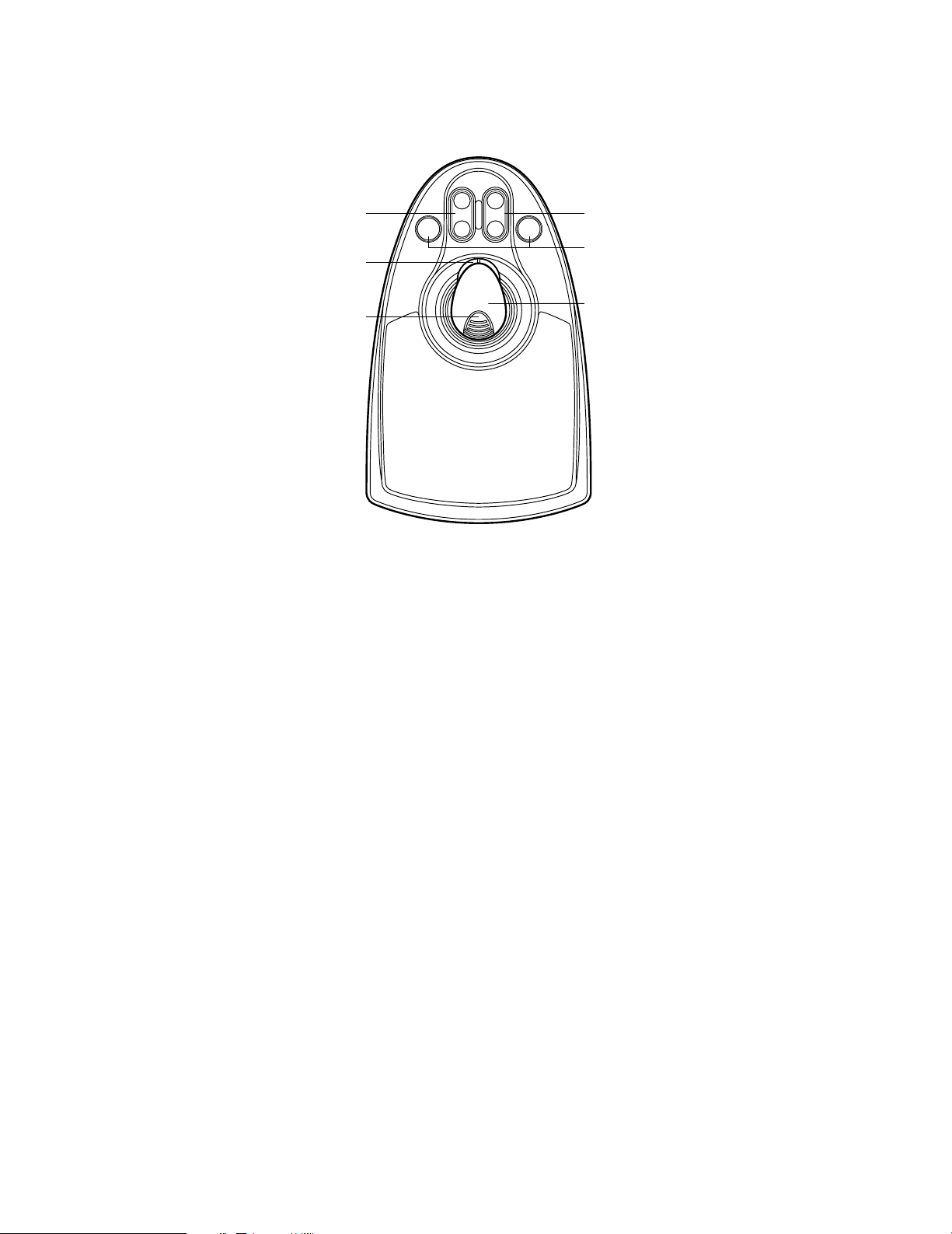
■ 3D Joystick Unit
This joystick unit is used to operate combination cameras and pan/tilt heads manually.
OPEN
FAR
IRIS
%2 %3
A B
%1
CLOSE
FOCUS
NEAR
%4
%0
%0 Top button
The top button is pressed to recall a function already
assigned.
%1 Zoom wheel controller
This controller is used for zooming cameras equipped
with specific lenses.
%2 Iris control buttons (IRIS CLOSE, OPEN)
These buttons close or open the lens iris of cameras
equipped with specific lenses.
%5
%3 Focus control buttons (FOCUS NEAR, FAR)
These buttons adjust the lens focus of cameras
equipped with specific lenses.
%4 A and B buttons (A, B)
These buttons recall functions you assign.
%5 3D joystick
Controls the panning and tilting of combination cameras and pan/tilt heads.
12
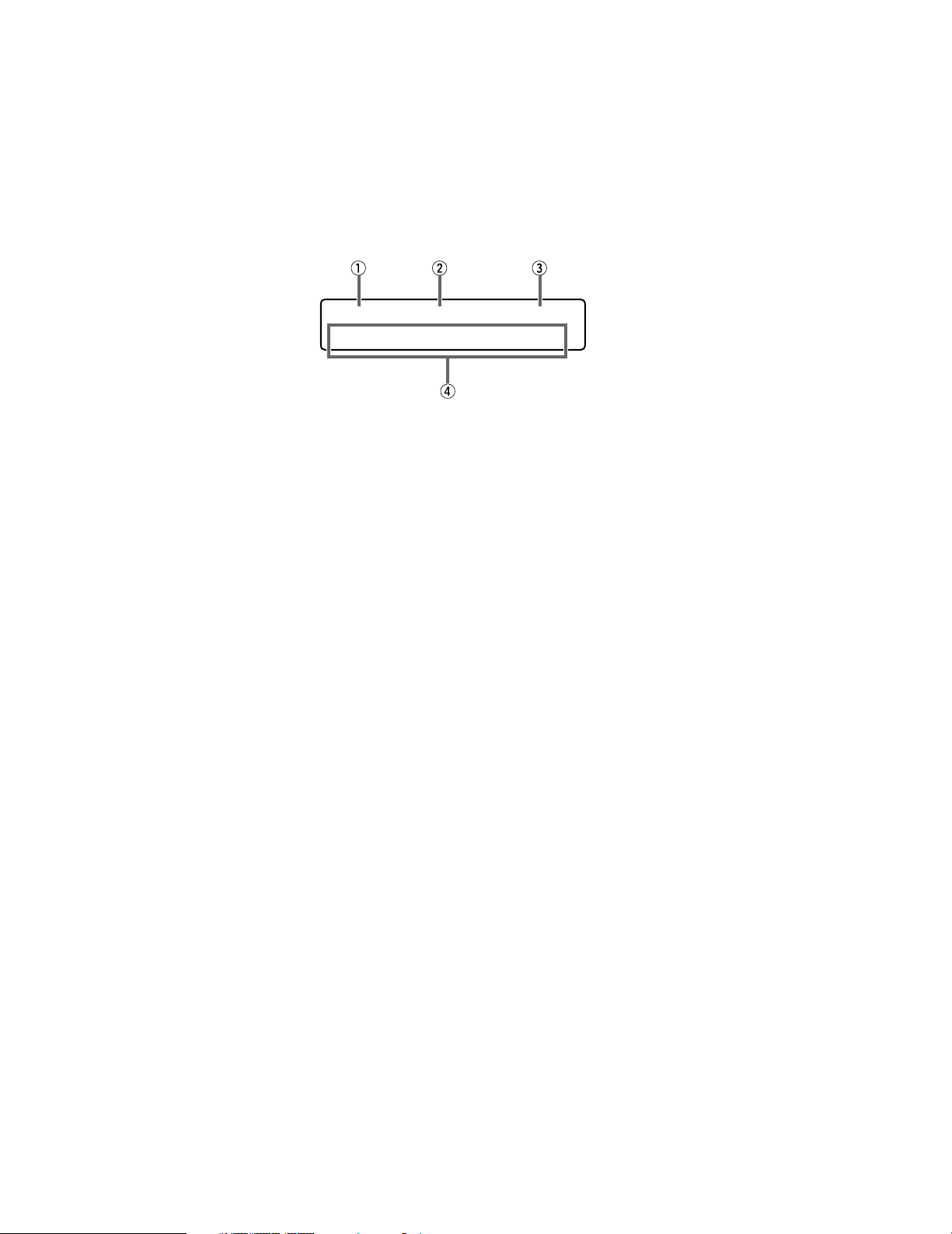
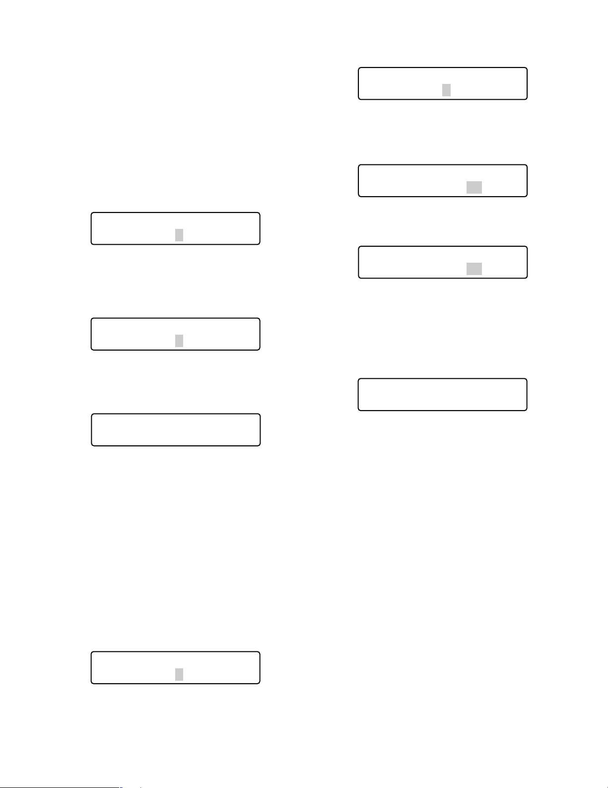
■ LCD Display Descriptions
The following are examples of LCD display after login.
Note: Some parts of LCD displays, described on this document, may differ from the actual status.
● Default Status (LCD Display After Login)
Mon02 Cam016 HD316
F1 F2 F3 F4
q Monitor number
The number of connected monitor is displayed. 1 to 99
can be displayed as a monitor number.
w Camera number
• The number of connected camera is displayed. 1 to
999 can be displayed as a camera number.
• When a camera position is specified, the camera position number is displayed.
• When a sequence is activated for a connected system
unit, «Seq» is displayed.
e Model number/Unit number
• The model number of connected system unit is displayed. When you select a system unit, the unit number
of connected system unit is displayed. The following
are examples of model number display.
«HD500»: Digital Disk Recorder WJ-HD500 Series
«SX150A»: Matrix Switcher WJ-SX150A
Note: The model number is abbreviated when an actual
model number exceeds 6 characters.
• When you press the RECORDER/UNIT button, the unit
number of connected system unit appears. 1 to 99 can
be displayed as a unit number.
• Numerics you have entered are displayed on this area.
r Function number (F1 to F8)/LCD title
• In the factory default, function numbers “F1” to “F4” are
displayed. “F5” to “F8” are displayed while holding
down the SHIFT button.
• The LCD titles, assigned to function buttons (F1 to
F4/F5 to F8), can also be displayed. You can edit the
function names in up to 20 alphanumeric characters.
You can display F5 to F8 function names while holding
down the SHIFT button.
13
● Main Menu (Menu Functions)
LCD MENU CAM 101
Camera Setup
q Category
The category of selected menu function is displayed.
w Function number
The function number of selected menu function is displayed.
Note: Refer to p. 48 Menu Function Categories.
● Sub Menu (Menu Functions)
Camera Setup 101
On Off Rst A.Rst
F1 F2 F3 F4
q Menu name
The name of selected menu function is displayed.
w Function number
The function number of selected menu function is displayed.
e Function name
The name of selected menu function is displayed.
e Button actions
The actions activated by the function (F1 to F4) buttons
are displayed. When pressed while holding down the
SHIFT button, actions of F5 to F8 buttons are displayed.
Note: When the selected button function has no button
actions, nothing is displayed on this area.
● Blinking
In this document, grayed areas on the illustrations mean blinking.
Mmm/DD/YYYY HH:MM 12
Mar/17/2004 12:00 AM
Blinking
14
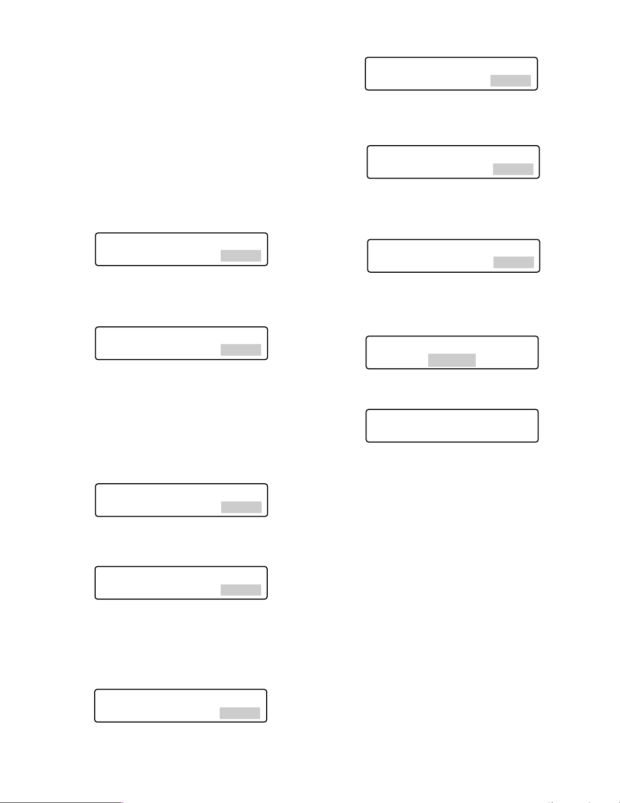
● Messages Displayed on the LCD
Invalid
Invalid
This message is displayed in the following circumstances.
• When you have entered a wrong user ID or password,
etc.
•When you have a camera number or menu number, etc.
that is not existing.
Busy
• When a selected monitor is controlled by a higher-level
user, the monitor number and “Busy” blinks on the LCD.
(You cannot control the monitor.)
• When a selected camera is controlled by a higher-level
user, the camera number and “Busy” blinks on the
LCD. (You cannot control the camera.)
• To cancel the Busy status, select another monitor, or
wait until “Busy” goes out.
Prohibited
Mon02 Cam016 HD316
Prohibited
• When you have tried an operation not authorized by the
function level setting, camera level setting, or selected
system unit, “Prohibited” blinks on the LCD.
• When you have forgotten to select a system unit or
monitor before selecting a camera, “Prohibited” blinks
on the LCD.
• When you have selected a system unit disconnected
from the system, “Prohibited” blinks on the LCD.
• After a few seconds, the LCD display will return to the
default status.
Notes:
• After a few seconds, this message will automatically
disappear.
• The illustration is an example in which a camera number other than 1 to 256 has been entered.
• In this document, gray area on illustration shows blinking.
Mon02 Cam016 HD316
Busy
«Busy» status is activated for a monitor.
Mon02 Cam016 HD316
Busy
«Busy» status is activated for a camera.
Controller No.1 No Exist Error
Controller No.1
No Exist Error
This message is displayed when no system controller is set
to CONTROLLER NO.1. Check that a system controller is
set to CONTROLLER NO. 1 (Refer to p. 18 CONTROLLER
NO. Switch Setting.)
15

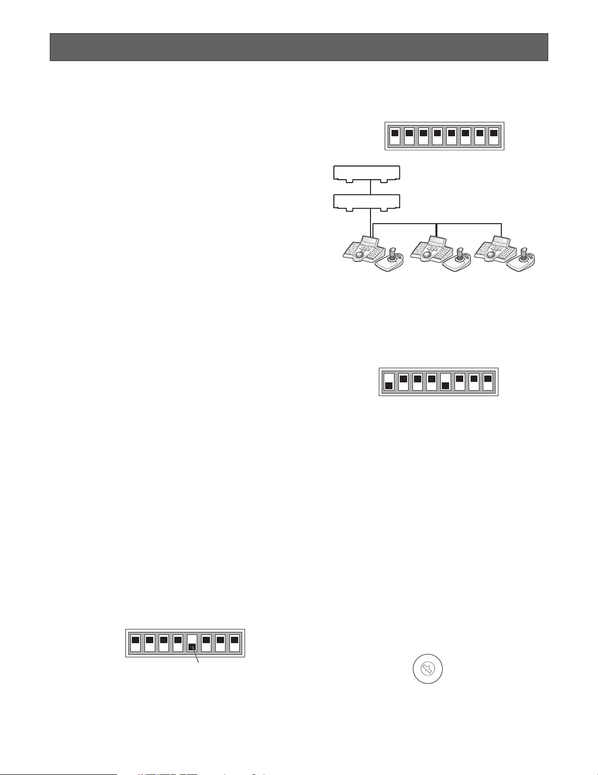
INSTALLATIONS AND CONNECTIONS
DC9V IN
MODE
DATA
SERIAL
CONTROLLER
NO.
JOYSTICK
0
9
8
7
6
5
4
3
2
1
System Controller
WV-CU650
(Main unit)
Modular cable (supplied)
Used when adding other WV-CU650
system controllers (Available up to 3)
To PS·Data ports
0
9
8
7
6
5
4
3
2
1
Fixed
PS·Data Mode
Line termination: ON
Refer to p. 18 for details on settings.
CONTROLLER No.: 1
MODE
OFF
ON
Camera 8 Camera 91to Camera 12 Camera 13 Camera 16Camera 1
Monitor 1
Monitor 2
• • •
• • •
• • • • • •
• • • • • • • • • • • •
to
41 4
Data Multiplex Unit
WJ-MP204C
(Two units)
Daisy Chain
Connection Kit
WV-CA48/10K
PS·Data
PS·Data
198121613
• • •
• • •
• • •
14
• • •
14
14
7
8
9
11 12
13 14 15 16
10/0
526
3
Digital Disk Recorder WJ-HD300 Series
POWER
ON
OFF
ALARM
Data Multiplex Unit WJ-MP204
ALARM
SUSPEND
1234
ESCSET
RESET
SUSPEND SET UP
ALARM
UNIT
0
9
8
7
6
5
4
3
2
1
POWER
ON
OFF
ALARM
Data Multiplex Unit WJ-MP204
ALARM
SUSPEND
1234
ESCSET
RESET
SUSPEND SET UP
ALARM
UNIT
0
9
8
7
6
5
4
3
2
1
WARNING
The installations described in the figures should be
made by qualified service personnel or system
installers
■ Basic System Connections
The following is an example in which a recorder and data multiplex units are connected.
.
16
■ Connection with the 3D Joystick Unit
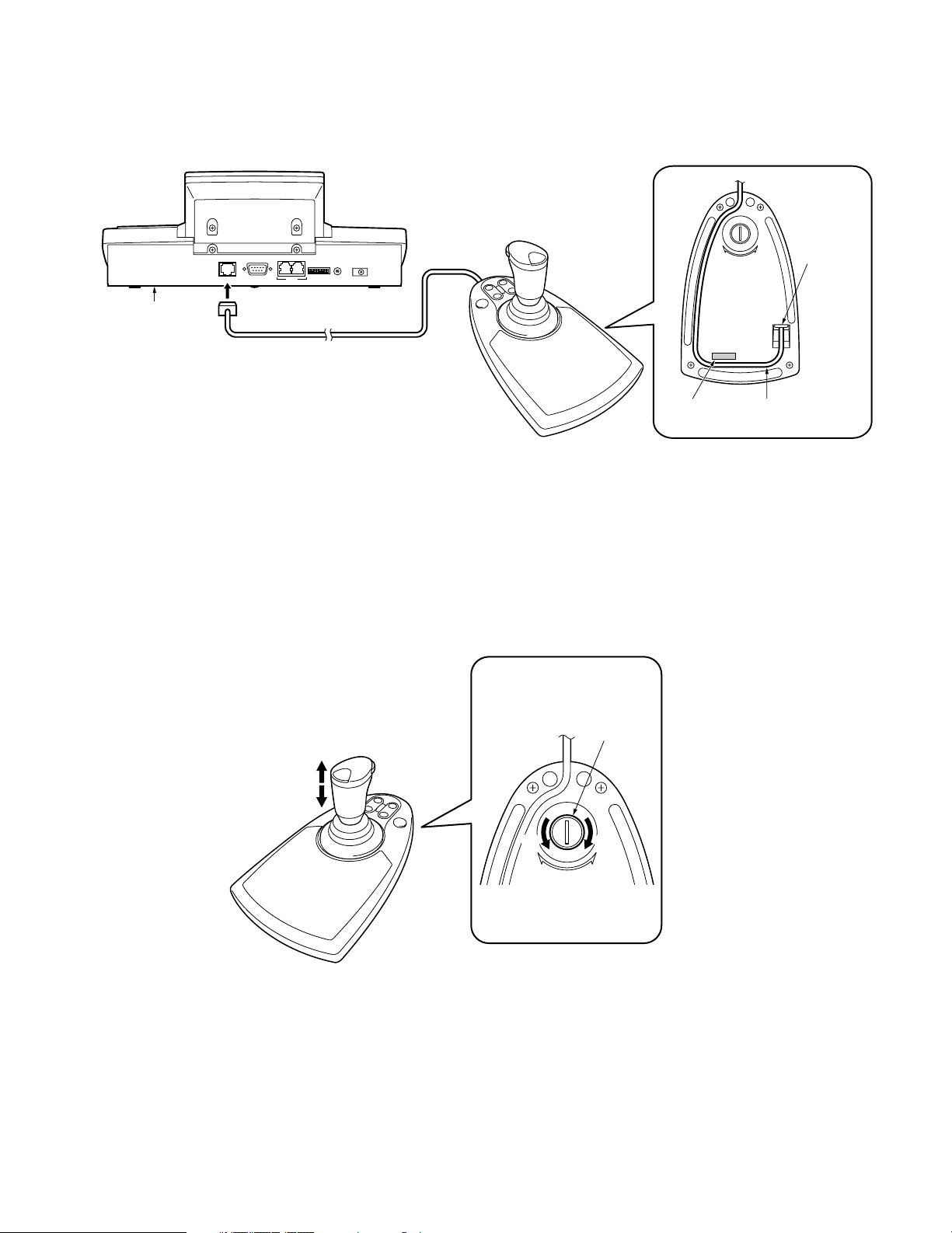
Connect the main unit and 3D joystick unit as follows.
Main unit
3D joystick unit
0
1
9
2
8
3
7
4
6
5
MODE
CONTROLLER
DATA
NO.
Cable (supplied)
DC9V IN
Combination code label
has been stuck
on the bottom.
JOYSTICK
SERIAL
Bottom side
DOWN
UP
Cable
connector
Note: Use the main unit and 3D joystick unit whose combination codes are identical.
■ Adjustment of 3D Joystick
To adjust the altitude of 3D joystick, turn the adjusting screw to the right or left.
Bottom side
Adjusting
Up
Down
screw
Combination
code label
Fit the cable
into the cable trench.
DOWN
UP
17
SETUP PROCEDURES (HARDWARE)
■ Setup Procedures
Perform the setup as follows.
1. Set the MODE switches.
You will set up the communication mode and line termination ON/OFF of RS-485 communication. (Refer to
MODE Switch Setting.)
2. Set CONTROLLER NO. switches.
You will perform this setting when using two or more
system controllers in daisy chain connections. (Refer to
CONTROLLER NO. Setting.)
3. Perform WV-CU650 setups after entering the
administrator password.
You will perform the settings concerning password and
communication between system controllers and other
system units, etc. (Refer to p. 19.)
Note: Before performing WV-CU650 setups, you need to
log into the system by entering the administrator password. (Refer to p. 19.)
■ MODE Switch Setting
2. Set the Line termination switch of other system controllers to OFF.
1234 567 8
OFF
ON
System units
Line termination ON
Line termination OFF
Line termination OFF Line termination OFF Line termination ON
● Setting for Terminal Mode
Set the MODE Switch #1 and #5 to ON.
1234 567 8
OFF
ON
You will perform the setting of the MODE switches at the
rear panel.
Notes:
• Before the setting, turn off the system controller. (Refer
to p. 27 Power-off.)
• Do not move the MODE switches to positions other than
described in these illustrations. That may cause malfunction.
● Setting for PS·Data Mode
If using only one system controller
Set the MODE Switch #5 to ON.
1234 567 8
OFF
ON
MODE Switch #5 (Line termination switch)
If using two or more system controllers in
daisy chain connections
1. Set the MODE Switch #5 of the system controller at the
chain end to ON.
18
Note: Refer to the following document for details on con-
nections and operations.
Addendum for WV-CU650 and WJ-SX150 Series
■ CONTROLLER NO. Switch
Setting
You will determine controller-number settings by moving
the CONTROLLER NO. switch at the rear panel.
If using only one system controller
Maintain the switch setting as “1 (factory default position)”.
If using two or more system controllers in
daisy chain connections
Up to 4 system controllers are connectable in the system.
To avoid conflict, set the unique number for each system
controller.
0
1
9
2
8
3
7
4
6
5
CONTROLLER No.
Notes:
• “0” and “9” are reserved numbers. They cannot be set
for controller numbers.
• One of the system controllers must be set to «1».

SETUP PROCEDURES (FIRMWARE)
■ Administrator Password Entry
If you log into the system in the administrator mode,
PS·Data communication setting, all reset, operator password check. and database copy will become available.
To activate the administrator mode, you need to enter the
administrator password.
Notes:
• The factory default of administrator password is “650”.
However, for security, you should change the password
setting. To change the setting, refer to p. 24.
• Take a note of your administrator password.
■ Setting Modes
If you power on the system controller while pressing the following buttons, the system will run in an associated setting
mode.
Notes:
• You cannot change the system from the following
modes (refer to the diagram) to the normal operation
mode. To start up the normal operation mode, turn off
the system controller, and then turn on the controller
again.
• The administrator password entry is required for the following modes.
Buttons pressed
while
the power-on
2, 4, and 6
MON (ESC) and 6
MON (ESC) and 1 Administrator
MON (ESC) and 2
MON (ESC) and 4
* The panning, tilting, and zooming calibration settings are
not restored.
Setting Mode
All reset
PS·Data
Communication
setting
password change
PS·Data database
copy
PS·Data password
display
Description
The communication
settings and
PS·Data database
can be restored to
the factory default.*
PS·Data communication setting can
be performed.
The administrator
password can be
changed.
The PS·Data database can be copied
from the source
system controller
(Controller No. 1) to
a destination system controller.
The passwords of
up to 16 operators
can be displayed
on the LCD.
19
■ All Reset
When the all reset mode is activated, all of the following settings will be reset to the factory default.
4. Press the CAM (SET) button.
If the password entered is correct, all the settings will
be reset to the factory default.
• Administrator password
• PS·Data communication setting
• LCD brightness, contrast, alarm buzzer, and button
buzzer settings
• Button functions and joystick button functions (F1 to F8,
A, B, and top buttons)
• Controller functions
(Time & Date Type)
(Auto Login)
(Operator Setup)
(Function Level)
(Camera Level)
(Cam Posi Map)
(Cam-Unit Map)
(HDD-Unit Map)
(LCD Title)
Note: Calibration settings of panning, tilting, and zooming
will be maintained even after all reset.
● Operation
1. Turn off the power.
If you set the MODE Switch #1 to #4 to ON, you
Note:
can skip entering the administrator password in
Step 3.
2. Turn on the power while holding down the buttons
2, 4, and 6.
“Admin Password” will appear on the LCD to enter the
password.
All Reset All Reset
5. Check “End” on the LCD.
Check “End” has appeared on the LCD to inform you of
the initialization end.
All Reset
End
6. Turn off the power.
■ PS·Data Communication Setting
This setting is required to establish a connection between
the system units and system controller.
List of PS·Data communication settings
Setting Item Available setting parameter(s)
Baud Rate 4800 / 9600 / 19200 bps
Data Bit 8 bit
Parity Bit None
Stop Bit 1
Wait Time OFF
Group Adr A to Z
Xon/Xoff Not Use (Fixed)
(Fixed)
/ Odd / Even
/ 2 bit
/ 100 msec / 200 msec /
400 msec / 1000 msec
All Reset
Admin Password _____
3. Enter the administrator password.
The password entered will be displayed as “∗” marks.
All Reset
Admin Password ∗∗∗∗∗
Notes:
• The factory default is “650”.
• To delete a character, press the CLEAR button.
• If you have entered a wrong password, the LCD
display will return to Step 2.
20
Note: Factory defaults are underlined.
● Operation
1. Turn off the power.
2. Turn on the power while holding down the button 6
and MON (ESC) button.
“Admin Password” will appear on the LCD to enter the
password.
•
PS Data Com. Setup
Admin Password _____
3. Enter the administrator password.
The password entered will be displayed as “∗” marks.
•
PS Data Com. Setup
Admin Password ∗∗∗∗∗
Wait time
•
PS Data Com. Setup
Wait Time Off
Notes:
• The factory default is “650”.
• To delete a character, press the CLEAR button.
4. Press the CAM (SET) button.
If the password entered is correct, «Baud Rate» setting
form will appear on the LCD.
•
PS Data Com. Setup
Baud Rate 9600
Notes:
• If the password entered is wrong, “PS·Data Com.
Setup” will appear on the LCD again to reenter the
password.
• You can change the setting item display on the LCD
by rotating the JogDial.
5. Select an item you wish to set up by rotating the
JogDial.
Baud rate
•
PS Data Com. Setup
Baud Rate 9600
The speed of communication between the system controller
and other system units
The wait time until the data is sent again (Refer to p. 22 for
details.)
Controller group address
•
PS Data Com. Setup
Cnt G—Adr. A
(No need for setup) Remain the factory default.
System unit group address
•
PS Data Com. Setup
Sys G—Adr.
(No need for setup) Remain the factory default.
6. Perform the settings.
Setting procedures differ depends on items. Refer to p.
21 to 23 for how to operate.
7. After you have completed the settings, turn off the
power.
● Baud Rate Setting
1. Select “Baud Rate” by rotating the JogDial.
(Refer to Step 5 in Operation.)
Parity bit
•
PS Data Com. Setup
Parity Bit None
The parity bit, added to the data, to perform parity check
(Refer to p. 22 for details.)
Stop bit
•
PS Data Com. Setup
Stop Bit 1
The stop bit, added to the last of data, in asynchronous
communication (Refer to p. 22 for details.)
2. Press the CAM (SET) button.
The LCD display will change from the display mode to
the editing mode.
•
PS Data Com. Setup
Baud Rate 9600
3. Select a desired parameter by rotating the JogDial,
or pressing the + or – button.
You can select the desired parameter from “19200”,
“9600”, and “4800”. The factory default is “9600”.
•
PS Data Com. Setup
Baud Rate 4800
Note: Conform this parameter to the baud rate of other sys-
tem units. Otherwise, communication will not be established between the system controller and system units.
21

4. Press the MON (ESC) button.
The selected parameter will be determined, and the
LCD display will return from the editing mode to the display mode.
•
PS Data Com. Setup
Baud Rate 4800
● Parity Bit Setting
1. Select “Parity Bit” by rotating the JogDial.
(Refer to Step 5 in p. 21.)
2. Press the CAM (SET) button.
The LCD display will change from the display mode to
the editing mode.
•
•
PS Data Com. Setup
PS Data Com. Setup
Parity Bit None
Parity Bit None
3. Select a desired parameter by rotating the JogDial
or pressing the + or – button.
You can select the desired parameter from “None”,
“Odd”, and “Even”. The factory default is “None”.
•
PS Data Com. Setup
Parity Bit Even
3. Select a desired parameter by rotating the JogDial
or pressing the + or – button.
You can select the desired parameter from “1” (bit) and
“2”. The factory default is “1”.
•
PS Data Com. Setup
Stop Bit 2
4. Press the MON (ESC) button.
The selected parameter will be determined, and the
LCD display will return from the editing mode to the display mode.
•
PS Data Com. Setup
Stop Bit 2
● Wait Time Setting
1. Select “Wait Time” by rotating the JogDial.
(Refer to Step 5 in p. 21.)
2. Press the CAM (SET) button.
The LCD display will change from the display mode to
the editing mode.
•
PS Data Com. Setup
Wait Time Off
4. Press the MON (ESC) button.
The selected parameter will be determined, and the
LCD display will return from the editing mode to the display mode.
•
PS Data Com. Setup
Parity Bit Even
● Stop Bit Setting
1. Select “Stop Bit” by rotating the JogDial.
(Refer to Step 5 in p. 21.)
2. Press the CAM (SET) button.
The LCD display will change from the display mode to
the editing mode.
•
PS Data Com. Setup
Stop Bit 1
3. Select a desired parameter by rotating the JogDial
or pressing the + or – button.
You can select the desired parameter from “Off”, “100
(msec)”, “200”, “400”, and “1000”.
•
PS Data Com. Setup
Wait Time 100
4. Press the MON (ESC) button.
The LCD display will return from the editing mode to the
display mode, and the selected parameter will be
determined.
•
PS Data Com. Setup
Wait Time 100
22
● Group Address Setting for System
Controller
Note: Remain the factory default. When you have mistaken-
ly changed the setting, recover the factory default as
follows.
1. Select “Cnt G-Adr.” by rotating the JogDial.
(Refer to Step 5 in p. 21.)
3. Select «A» by rotating the JogDial or pressing the +
or – button.
•
PS Data Com. Setup
Sys G—Adr.A
4. Press the CAM (SET) button.
The parameter will be determined, and the cursor will
jump to the sub parameter.
2. Press the CAM (SET) button.
The LCD display will change from the display mode to
the editing mode.
•
PS Data Com. Setup
Cnt G—Adr.B
3. Select a desired parameter by rotating the JogDial
or pressing the + or – button.
You can select the desired parameter from “A” to “Z”.
The factory default is “A”.
•
PS Data Com. Setup
Cnt G—Adr.A
4. Press the MON (ESC) button.
The selected parameter will be determined, and the
LCD display will return to the display mode.
•
PS Data Com. Setup
Cnt G—Adr.A
● Group Address Setting for System
Units
Note: Remain the factory default. When you have mistaken-
ly changed the setting, recover the factory default as
follows.
•
PS Data Com. Setup
Sys G—Adr.A 05
5. Enter the unit number of system unit by rotating the
JogDial or pressing the + or – button.
•
PS Data Com. Setup
Sys G—Adr.A 01
Note:
1 to 99 is available for the unit number. The facto-
ry default is 01.
6. Press the CAM (SET) button.
The sub parameter will be determined, and «OK» will
appear on the LCD.
•
PS Data Com. Setup
Sys G—Adr.A 01 OK
After a second, the LCD display will return to the status
in Step 5.
If you set the unit numbers of other system units, repeat
Step 5.
Note: If the parameters cannot be determined, «NG» will
appear on the LCD. In this case, check the unit
number of system unit, and repeat Step 3 to 6.
7. Press the MON (ESC) button.
The LCD display will return to the status in Step 2.
1. Select “Sys G-Adr.” by rotating the JogDial.
(Refer to Step 5 in p. 21.)
2. Press the CAM (SET) button.
The LCD display will change from the display mode to
the editing mode.
•
PS Data Com. Setup
Sys G—Adr.B
8. Press the MON (ESC) button again.
The LCD display will return from the editing mode to the
display mode.
23
■ To Change the Administrator
Password
You can change the administrator password. The factory
default is “650”.
● Operation
7. Enter a new administrator password.
Admin Password Setup
New Password ∗∗∗∗∗
8. Press the CAM (SET) button.
“New Password” entry form will appear again.
1. Turn off the power.
2. Turn on the power while holding down the button 1
and MON (ESC) button.
“Admin Password” entry form will appear to perform the
setting.
Admin Password Setup
Admin Password _____
3. Enter the current administrator password.
The password entered will be displayed as “∗” marks.
Admin Password Setup
Admin Password ∗∗∗∗∗
Notes:
• The factory default is “650”.
• To delete a character, press the CLEAR button.
4. Press the CAM (SET) button.
If the password entered is correct, “Old Password”
entry form will appear.
Admin Password Setup
Old Password _____
Admin Password Setup
PS・Data Com. Setup
New Password _____
Cut G−Adr.B
9. Enter the new administrator password again.
The password entered will be displayed as “∗” marks.
Admin Password Setup
New Password ∗∗∗∗∗
10. Press the CAM (SET) button.
The new password has been memorized in the system,
and “Memory” will appear on the LCD.
Admin Password Setup
Memory
Then, “End” will appear on the LCD.
Admin Password Setup
End
Note: If the new password entered is wrong, the LCD
display will return to Step 4. Enter the old password
again.
11. Turn off the power.
5. Enter the current administrator password again.
The password entered will be displayed as “∗” marks.
Admin Password Setup
Old Password ∗∗∗∗∗
Note: To delete a character, press the CLEAR button.
6. Press the CAM (SET) button.
If the password entered is correct, “New Password”
entry form will appear.
Admin Password Setup
New Password _____
Note: If the old password entered is wrong, the LCD
display will return to Step 4. Enter the old password
again.
24
Loading…
Скачать
Before attempting to connect or operate this product,
please read these instructions carefully and save this manual for future use.
Model No.
WV-CU650
System Controller
Operating Instructions
На этой странице вы можете совершенно бесплатно скачать Руководство по эксплуатации Panasonic WV-CU650.
У документа PDF Руководство по эксплуатации 78 страниц, а его размер составляет 1.24 Mb.
Читать онлайн Аналоговые камеры слежения Panasonic WV-CU650 Руководство по эксплуатации
Скачать файл PDF «Panasonic WV-CU650 Руководство по эксплуатации» (1.24 Mb)
Популярность:
4066 просмотры
Подсчет страниц:
78 страницы
Тип файла:
Размер файла:
1.24 Mb
Прочие инструкции Panasonic WV-CU650
Прочие инструкции Panasonic Аналоговые камеры слежения
Прочие инструкции Panasonic
- Addeddate
- 2021-02-14 17:54:49
- Identifier
- manuallib-id-2591139
- Identifier-ark
- ark:/13960/t3jx8wg1f
- Ocr
- tesseract 5.0.0-alpha-20201231-10-g1236
- Ocr_autonomous
- true
- Ocr_detected_lang
- en
- Ocr_detected_lang_conf
- 1.0000
- Ocr_detected_script
- Latin
- Ocr_detected_script_conf
- 1.0000
- Ocr_module_version
- 0.0.12
- Ocr_parameters
- -l eng+Latin
- Page_number_confidence
- 87.01
comment
Reviews
There are no reviews yet. Be the first one to
write a review.
47
Views
DOWNLOAD OPTIONS
Temporarily Unavailable
DAISY
For users with print-disabilities
Temporarily Unavailable
EPUB
Uploaded by
chris85
on
FREE ENGLISH PANASONIC WV-CU650 (03) PDF USER GUIDE
FREE ENGLISH PANASONIC WV-CU650 (03) PDF USER MANUAL
FREE ENGLISH PANASONIC WV-CU650 (03) PDF OWNER GUIDE
FREE ENGLISH PANASONIC WV-CU650 (03) PDF OWNER MANUAL
FREE ENGLISH PANASONIC WV-CU650 (03) PDF REFERENCE GUIDE
FREE ENGLISH PANASONIC WV-CU650 (03) PDF INSTRUCTION GUIDE
FREE ENGLISH PANASONIC WV-CU650 (03) PDF REFERENCE MANUAL
FREE ENGLISH PANASONIC WV-CU650 (03) PDF INSTRUCTION MANUAL
FREE ENGLISH PANASONIC WV-CU650 (03) PDF OPERATING INSTRUCTIONS
CLICK HERE TO DOWNLOAD PANASONIC WV-CU650 (03) PDF MANUAL
If this is not the document you want for this product, click here to see if we have any other documents for this product.
CLICK HERE TO DOWNLOAD PANASONIC WV-CU650 (03) PDF MANUAL