

AV Receiver
TX-SR607
Contents
Introduction …………………………….. 2
Connection …………………………….15
Instruction Manual
Thank you for purchasing an Onkyo AV Receiver.
Please read this manual thoroughly before making
connections and plugging in the unit.
Following the instructions in this manual will enable
you to obtain optimum performance and listening
enjoyment from your new AV Receiver.
Please retain this manual for future reference.
Turning On & First Time Setup
Basic Operations…………………….51
Using the Listening Modes ……..62
Advanced Setup ……………………..69
Zone 2 …………………………………..85
Controlling Other Components
Others………………………………….. 100
…..38
….89
E
n
WARNING:
TO REDUCE THE RISK OF FIRE OR ELECTRIC
SHOCK, DO NOT EXPOSE THIS APPARATUS TO
RAIN OR MOISTURE.
CAUTION:
TO REDUCE THE RISK OF ELECTRIC SHOCK,
DO NOT REMOVE COVER (OR BACK). NO
USER-SERVICEABLE PARTS INSIDE. REFER
SERVICING TO QUALIFIED SERVICE
PERSONNEL.
Important Safety Instructions
WARNING
RISK OF ELECTRIC SHOCK
DO NOT OPEN
The lightning flash with arrowhead symbol, within an
equilateral triangle, is intended to alert the user to the
presence of uninsulated “dangerous voltage” within
the product’s enclosure that may be of sufficient
magnitude to constitute a risk of electric shock to
persons.
The exclamation point within an equilateral triangle is
intended to alert the user to the presence of important
operating and maintenance (servicing) instructions in
the literature accompanying the appliance.
AVIS
RISQUE DE CHOC ELECTRIQUE
NE PAS
OUVRIR
1. Read these instructions.
2. Keep these instructions.
3. Heed all warnings.
4. Follow all instructions.
5. Do not use this apparatus near water.
6. Clean only with dry cloth.
7. Do not block any ventilation openings. Install in
accordance with the manufacturer’s instructions.
8. Do not install near any heat sources such as radiators, heat registers, stoves, or other apparatus
(including amplifiers) that produce heat.
9. Do not defeat the safety purpose of the polarized or
grounding-type plug. A polarized plug has two
blades with one wider than the other. A grounding
type plug has two blades and a third grounding
prong. The wide blade or the third prong are provided for your safety. If the provided plug does not
fit into your outlet, consult an electrician for
replacement of the obsolete outlet.
10. Protect the power cord from being walked on or
pinched particularly at plugs, convenience receptacles, and the point where they exit from the apparatus.
11. Only use attachments/accessories specified by the
manufacturer.
12. Use only with the cart, stand,
PORTABLE CART WARNIN
tripod, bracket, or table specified by the manufacturer, or
sold with the apparatus.
When a cart is used, use caution when moving the cart/
apparatus combination to
S3125A
avoid injury from tip-over.
13. Unplug this apparatus during lightning storms or
when unused for long periods of time.
14. Refer all servicing to qualified service personnel.
Servicing is required when the apparatus has been
damaged in any way, such as power-supply cord or
plug is damaged, liquid has been spilled or objects
have fallen into the apparatus, the apparatus has
been exposed to rain or moisture, does not operate
normally, or has been dropped.
15. Damage Requiring Service
Unplug the apparatus from the wall outlet and refer
servicing to qualified service personnel under the
following conditions:
A. When the power-supply cord or plug is dam-
aged,
B. If liquid has been spilled, or objects have fallen
into the apparatus,
C. If the apparatus has been exposed to rain or
water,
D. If the apparatus does not operate normally by
following the operating instructions. Adjust
only those controls that are covered by the operating instructions as an improper adjustment of
other controls may result in damage and will
often require extensive work by a qualified technician to restore the apparatus to its normal
operation,
E. If the apparatus has been dropped or damaged in
any way, and
F. When the apparatus exhibits a distinct change in
performance this indicates a need for service.
16. Object and Liquid Entry
Never push objects of any kind into the apparatus
through openings as they may touch dangerous voltage points or short-out parts that could result in a
fire or electric shock.
The apparatus shall not be exposed to dripping or
splashing and no objects filled with liquids, such as
vases shall be placed on the apparatus.
Don’t put candles or other burning objects on top of
this unit.
17. Batteries
Always consider the environmental issues and follow local regulations when disposing of batteries.
18. If you install the apparatus in a built-in installation,
such as a bookcase or rack, ensure that there is adequate ventilation.
Leave 20 cm (8″) of free space at the top and sides
and 10 cm (4″) at the rear. The rear edge of the shelf
or board above the apparatus shall be set 10 cm (4″)
away from the rear panel or wall, creating a fluelike gap for warm air to escape.
2

Precautions
1. Recording Copyright—Unless it’s for personal use
only, recording copyrighted material is illegal without the permission of the copyright holder.
2. AC Fuse—The AC fuse inside the unit is not userserviceable. If you cannot turn on the unit, contact
your Onkyo dealer.
3. Care—Occasionally you should dust the unit all
over with a soft cloth. For stubborn stains, use a soft
cloth dampened with a weak solution of mild detergent and water. Dry the unit immediately afterwards
with a clean cloth. Don’t use abrasive cloths, thinners, alcohol, or other chemical solvents, because
they may damage the finish or remove the panel lettering.
4. Power
WARNING
BEFORE PLUGGING IN THE UNIT FOR THE
FIRST TIME, READ THE FOLLOWING SECTION CAREFULLY.
AC outlet voltages vary from country to country.
Make sure that the voltage in your area meets the
voltage requirements printed on the unit’s rear panel
(e.g., AC 230 V, 50 Hz or AC 120 V, 60 Hz).
The power cord plug is used to disconnect this unit
from the AC power source. Make sure that the plug
is readily operable (easily accessible) at all times.
Pressing the [ON/STANDBY] button to select
Standby mode does not fully shutdown the unit. If
you do not intend to use the unit for an extended
period, remove the power cord from the AC outlet.
5. Preventing Hearing Loss
Caution
Excessive sound pressure from earphones and headphones can cause hearing loss.
6. Batteries and Heat Exposure
War nin g
Batteries (battery pack or batteries installed) shall
not be exposed to excessive heat as sunshine, fire or
the like.
7. Never Touch this Unit with Wet Hands—Never
handle this unit or its power cord while your hands
are wet or damp. If water or any other liquid gets
inside this unit, have it checked by your Onkyo
dealer.
8. Handling Notes
• If you need to transport this unit, use the original
packaging to pack it how it was when you originally bought it.
• Do not leave rubber or plastic items on this unit
for a long time, because they may leave marks on
the case.
• This unit’s top and rear panels may get warm
after prolonged use. This is normal.
• If you do not use this unit for a long time, it may
not work properly the next time you turn it on, so
be sure to use it occasionally.
For U.S. models
FCC Information for User
CAUTION:
The user changes or modifications not expressly
approved by the party responsible for compliance could
void the user’s authority to operate the equipment.
NOTE:
This equipment has been tested and found to comply
with the limits for a Class B digital device, pursuant to
Part 15 of the FCC Rules. These limits are designed to
provide reasonable protection against harmful interference in a residential installation.
This equipment generates, uses and can radiate radio frequency energy and, if not installed and used in accordance with the instructions, may cause harmful
interference to radio communications. However, there is
no guarantee that interference will not occur in a particular installation. If this equipment does cause harmful
interference to radio or television reception, which can
be determined by turning the equipment off and on, the
user is encouraged to try to correct the interference by
one or more of the following measures:
• Reorient or relocate the receiving antenna.
• Increase the separation between the equipment and
receiver.
• Connect the equipment into an outlet on a circuit different from that to which the receiver is connected.
• Consult the dealer or an experienced radio/TV technician for help.
For Canadian Models
NOTE: THIS CLASS B DIGITAL APPARATUS
COMPLIES WITH CANADIAN ICES-003.
For models having a power cord with a polarized plug:
CAUTION: TO PREVENT ELECTRIC SHOCK,
MATCH WIDE BLADE OF PLUG TO WIDE SLOT,
FULLY INSERT.
Modèle pour les Canadien
REMARQUE: CET APPAREIL NUMÉRIQUE DE
LA CLASSE B EST CONFORME À LA NORME
NMB-003 DU CANADA.
Sur les modèles dont la fiche est polarisée:
AT TE NT IO N : POUR ÉVITER LES CHOCS ÉLEC-
TRIQUES, INTRODUIRE LA LAME LA PLUS
LARGE DE LA FICHE DANS LA BORNE CORRESPONDANTE DE LA PRISE ET POUSSER
JUSQU’AU FOND.
3
Precautions—Continued
Supplied Accessories
For British models
Replacement and mounting of an AC plug on the power
supply cord of this unit should be performed only by
qualified service personnel.
IMPORTANT
The wires in the mains lead are coloured in accordance
with the following code:
Blue: Neutral
Brown: Live
As the colours of the wires in the mains lead of this apparatus may not correspond with the coloured markings
identifying the terminals in your plug, proceed as fol-
lows:
The wire which is coloured blue must be connected to
the terminal which is marked with the letter N or
coloured black.
The wire which is coloured brown must be connected to
the terminal which is marked with the letter L or
coloured red.
IMPORTANT
The plug is fitted with an appropriate fuse. If the fuse
needs to be replaced, the replacement fuse must
approved by ASTA or BSI to BS1362 and have the same
ampere rating as that indicated on the plug. Check for the
ASTA mark or the BSI mark on the body of the fuse.
If the power cord’s plug is not suitable for your socket
outlets, cut it off and fit a suitable plug. Fit a suitable fuse
in the plug.
For European Models
Declaration of Conformity
We,
ONKYO EUROPE
ELECTRONICS GmbH
LIEGNITZERSTRASSE 6,
82194 GROEBENZELL,
GERMANY
declare in own responsibility, that the ONKYO product
described in this instruction manual is in compliance with the
corresponding technical standards such as EN60065,
EN55013, EN55020 and EN61000-3-2, -3-3.
GROEBENZELL, GERMANY
K. MIYAGI
ONKYO EUROPE ELECTRONICS GmbH
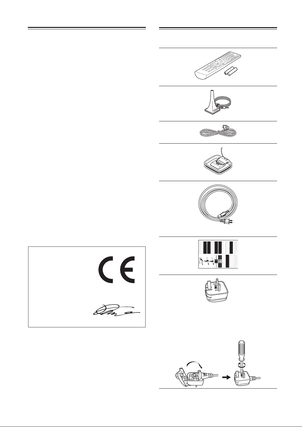
Make sure you have the following accessories:
Remote controller & two batteries (AA/R6)
Speaker setup microphone
Indoor FM antenna
AM loop antenna
Power cord (on some model)
(Plug type varies from country to country.)
LEFT
LEFT
LEFT
LEFT
LEFT
LEFT
RIGHT
RIGHT
FRONT
FRONT
FRONT
FRONT
SURROUND
SURROUND
FRONT
LEFT
SURROUND
FRONT
RIGHT
FRONT
LEFT
SURROUND
LEFT
FRONT
RIGHT
Speaker Cable
1
2
LEFT
LEFT
RIGHT
RIGHT
RIGHT
RIGHT
SURROUND
SURROUND
LEFT
SURROUND
RIGHT
SURROUND
RIGHT
RIGHT
CENTER
CENTER
SP-B/ZONE2
SP-B/ZONE2
SP-B/ZONE2
SP-B/ZONE2
SURROUND BACK
SURROUND BACK
SURROUND BACK
SURROUND BACK
SP-B/ZONE2
RIGHT
SURROUND BACK
RIGHT
CENTER
SURROUND BACK
LEFT
SP-B/ZONE2
RIGHT
SP-B/ZONE2
LEFT
SURROUND BACK
RIGHT
CENTER
SURROUND BACK
LEFT
RIGHT
SP-B/ZONE2
LEFT
LEFT
LEFT
LEFT
LEFT
RIGHT
RIGHT
RIGHT
RIGHT
FRONT HIGH
FRONT HIGH
FRONT HIGH
FRONT HIGH
FRONT WIDE
FRONT WIDE
FRONT WIDE
FRONT WIDE
3
FRONT HIGH
RIGHT
FRONT WIDE
LEFT
FRONT WIDE
LEFT
FRONT WIDE
RIGHT
FRONT WIDE
RIGHT
FRONT HIGH
RIGHT
FRONT HIGH
LEFT
FRONT HIGH
LEFT
Speaker cable labels
*
Power-plug adapter
Only supplied in certain countries. Use this adapter if
your AC outlet does not match with the plug on the AV
receiver’s power cord (adapter varies from country to
country).
*How to mount the AC plug:
* In catalogs and on packaging, the letter at the end of the product
name indicates the color. Specifications and operations are the
same regardless of color.
4
Features
Amplifier
• 90 Watts/Channel @ 8 ohms (FTC)
• 140 Watts/Channel @ 6 ohms (IEC)
• 175 Watts/Channel @ 6 ohms (JEITA)
• WRAT-Wide Range Amplifier Technology
(5 Hz-100 kHz bandwidth)
• Optimum Gain Volume Circuitry
• H.C.P.S. (High Current Power Supply) Massive High
Power Transformer
Processing
• HDMI Video Upscaling (to 1080i Compatible) with
Faroudja DCDi Edge Enhancement
• HDMI ver.1.3a with Repeater System (Deep Color,
x.v.Color, Lip Sync, DTS
DTS-HD High Resolution Audio, Dolby TrueHD
*2
-HD Master Audio,
*1
,
Dolby Digital Plus, SA-CD and Multi-CH PCM)
• Dolby Pro Logic IIz (with “Front High” Direction
Mode)
• DTS Surround Sensation Speaker Technology
*2
• Non-Scaling Configuration
• Direct Mode and Pure Audio Mode
• Music Optimizer*8 for Compressed Music
• 192 kHz/24-bit D/A Converters
• Powerful and Highly Accurate 32-bit DSP Processing
x 2
Connections
• 6 HDMI*3 Inputs (1 on front panel) and 1 Output
• Onkyo for System Control
• 4 Digital Inputs (2 Optical / 2 Coaxial)
• Component Video Switching (2 Inputs/1 Output)
• Front “Portable” Input for iPod and MP3 Players
• Universal Port for the Dock for iPod/HD Radio
*5
Dock (North American models) / DAB+ (European
models)
• Dual Subwoofer Pre Out
• Banana Plug-Compatible Speaker Posts
*4
• Powered Zone 2
• Bi-Amp Connectable for FL/FR with SBL/SBR
Miscellaneous
• 40 SIRIUS*6/AM/FM Presets (North American models)
• 40 AM/FM Presets (European and Asian models)
• Audyssey 2EQ
lems
• Audyssey Dynamic EQ
• Audyssey Dynamic Volume
Listening Level and Dynamic Range
• Crossover Adjustment
(40/50/60/80/100/120/150/200 Hz)
• A/V Sync Control Function (up to 100 ms)
• On-Screen Display via HDMI
• Aluminum Front Panel
™*7
to Correct Room Acoustic Prob-
™*7
for Loudness Correction
™*7
to Maintain Optimal
• Preprogrammed (with On-Screen Display Set-up)
u-Compatible Remote
*1.
Manufactured under license from Dolby Laboratories. “Dolby”,
“Pro Logic” and the double-D symbol are trademarks of Dolby
Laboratories.
*2.
Manufactured under license under U.S. Patent #’s: 5,451,942;
5,956,674; 5,974,380; 5,978,762; 6,226,616; 6,487,535;
7,212,872; 7,333,929; 7,392,195; 7,272,567 & other U.S. and
worldwide patents issued & pending. DTS is a registered trademark & the DTS logos, Symbol, DTS-HD Master Audio and
DTS Surround Sensation are trademarks of DTS, Inc.
©1996-2008 DTS, Inc. All Rights Reserved.
*3.
HDMI, the HDMI logo and High Definition Multimedia Interface are trademarks or registered trademarks of HDMI Licensing, LLC.
*4. In Europe, using banana plugs to connect speakers to an audio
amplifier is prohibited.
*5.
The HD Radio Ready logo is a proprietary trademark of iBiquity
Digital Corp.
*6.
SIRIUS, XM and all related marks and logos are trademarks of
Sirius XM Radio Inc. and its subsidiaries. All other marks and
logos are the property of their respective owners. All rights
reserved. SIRIUS subscription sold separately. Taxes and a onetime activation fee may apply. SIRIUS tuner required (sold separately) to receive the SIRIUS service. All programming and
fees subject to change. It is prohibited to copy, decompile, disassemble, reverse engineer, hack, manipulate or otherwise make
available any technology or software incorporated in receivers
compatible with the SIRIUS Satellite Radio System. Service not
available in Alaska or Hawaii.
*7.
Manufactured under license from Audyssey Laboratories. U.S.
and foreign patents pending. Audyssey 2EQ™,
Audyssey Dynamic Volume™ and Audyssey Dynamic EQ™
are trademarks of Audyssey Laboratories.
*8. Music Optimizer™ is a trademark of Onkyo Corporation.
* Apple and iPod are trademarks of Apple Inc., registered in the
U.S. and other countries.
* “x.v.Color” is a trademark of Sony Corporation.
This product incorporates copyright protection technology that
is protected by U.S. patents and other intellectual property
rights. Use of this copyright protection technology must be
authorized by Macrovision Corporation, and is intended for
home and other limited consumer uses only unless otherwise
authorized by Macrovision. Reverse engineering or disassembly is prohibited.
5
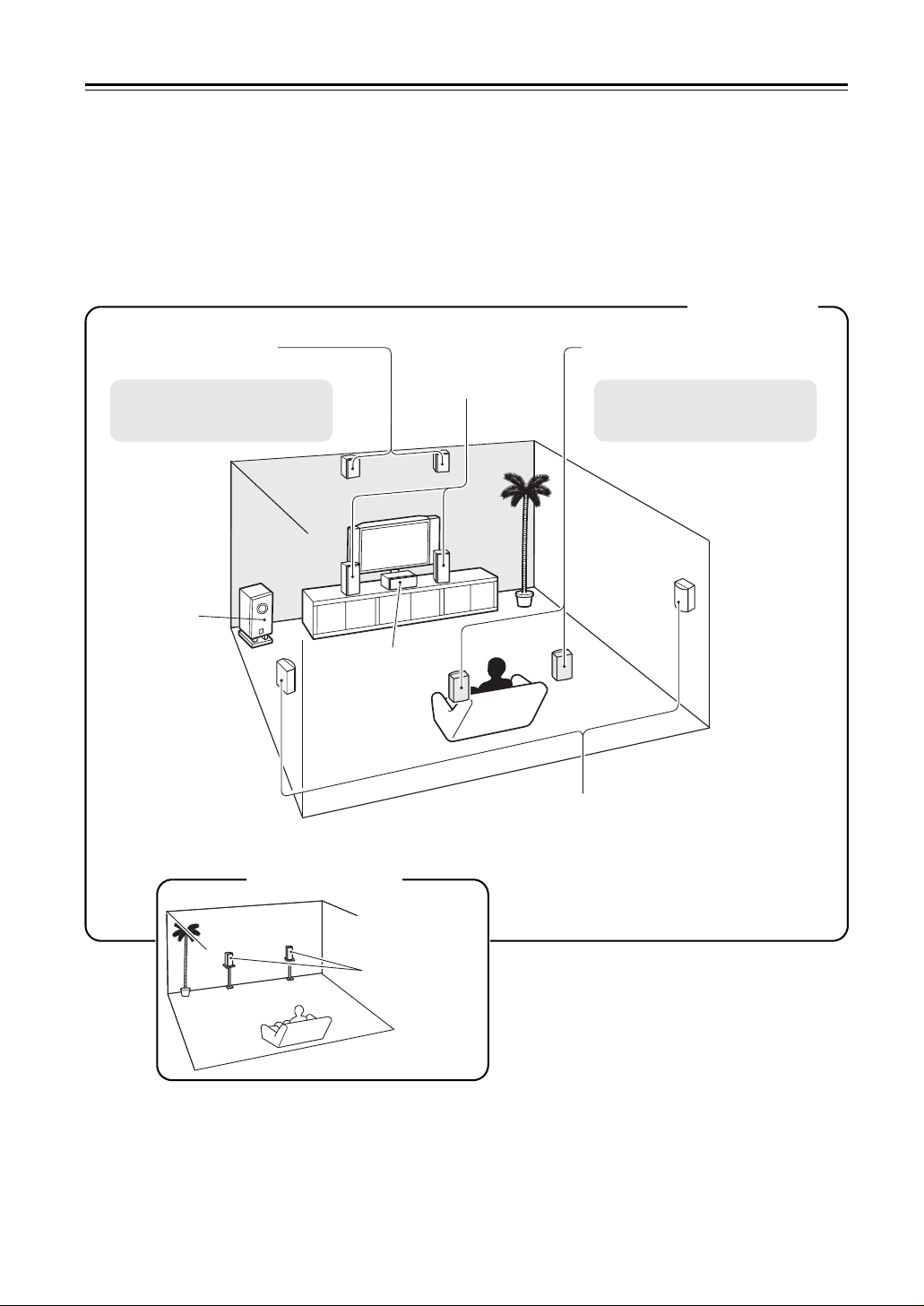
Multiroom Capability
You can use two speaker systems with this AV receiver—a surround-sound speaker system (up to 7.1 channels) in
your main listening room, a stereo speaker system in a second room, or Zone 2, as we call it. And, you can select a
different audio source for each room.
Main Room: In your main listening room, you can enjoy up to 7.1-channel playback (see page 15).
You can enjoy the various listening modes such as Dolby and DTS (see pages 62-68).
* While Powered Zone 2 is being used, playback is reduced to 5.1-channels (see page 85).
Zone 2: In your Zone 2 room, you can enjoy 2-channel stereo playback (see page 85).
* The listening modes cannot be used with Zone 2.
Main Room
Front high left and right
speakers
* While Powered Zone 2 is being
used, nothing is output by these
speakers (page 86).
Subwoofer
Front left and right
speakers
Center speaker
Surround back left and right
speakers
* While Powered Zone 2 is being
used, nothing is output by these
speakers (page 86).
Surround left and right speakers
Zone 2 Room
Left and right
stereo speakers
6
Contents
Introduction
Important Safety Instructions ……………………………… 2
Precautions ……………………………………………………… 3
Supplied Accessories………………………………………… 4
Features ………………………………………………………….. 5
Multiroom Capability………………………………………….. 6
Front & Rear Panels………………………………………….. 8
Front Panel…………………………………………………… 8
Display……………………………………………………….. 10
Rear Panel …………………………………………………. 11
Remote Controller …………………………………………… 13
Installing the Batteries ………………………………….. 13
Aiming the Remote Controller ……………………….. 13
Controlling the AV Receiver ………………………….. 14
Connection
About Home Theater……………………………………….. 15
Enjoying Home Theater………………………………… 15
Connecting the AV Receiver …………………………….. 16
Connecting Your Speakers …………………………… 16
Bi-amping the Front Speakers……………………….. 19
Connecting Antenna…………………………………….. 20
About AV Connections …………………………………. 22
Connecting Components with HDMI ………………. 23
Connecting Both Audio & Video …………………….. 25
Which Connections Should I Use?…………………. 25
Connecting a TV or Projector ………………………… 27
Connecting a DVD Player …………………………….. 28
Connecting a VCR or DVD Recorder for Playback
Connecting a VCR or DVD Recorder for Recording
Connecting a Satellite, Cable, Terrestrial
Set-top box, or Other Video Source……………… 31
Connecting a Game Console ………………………… 32
Connecting a Camcorder or Other Device ………. 33
Connecting a Portable Audio player……………….. 33
Connecting a CD Player or Turntable …………….. 34
Connecting a Cassette, CDR, MiniDisc,
or DAT Recorder……………………………………….. 35
Connecting an RI Dock ………………………………… 36
Connecting a Dock with the Universal Port
connector …………………………………………………. 36
Connecting Onkyo u Components ………………. 37
Connecting the Power Cord ………………………….. 37
….. 29
…. 30
Turning On & First Time Setup
Turning On the AV Receiver …………………………….. 38
Turning On and Standby ………………………………. 38
First Time Setup……………………………………………… 39
Using the Onscreen Setup Menus …………………. 39
Using the Display to change the settings ………… 39
Video Input Setup………………………………………… 40
Digital Input Setup ……………………………………….. 42
Speaker Settings …………………………………………. 43
TV Format Setup (not North American models)
FM/AM Frequency Step Setup (on some models)
Changing the Input Display …………………………… 45
Audyssey 2EQ™ Room Correction and
Speaker Setup ………………………………………….. 46
….. 44
…. 44
Basic Operations
Basic Operations…………………………………………….. 51
Selecting the Input Source ……………………………. 51
Adjusting the Bass & Treble………………………….. 52
Displaying Source Information ………………………. 52
Setting the Display Brightness ………………………. 52
Muting the AV receiver …………………………………. 53
Using the Sleep Timer………………………………….. 53
Using Headphones………………………………………. 53
Listening to the Radio………………………………………. 54
Using the Tuner …………………………………………… 54
Presetting AM/FM Stations……………………………. 55
Using RDS (European models only)……………….. 56
UP-A1 series Dock for iPod………………………………. 58
About the UP-A1 series Dock………………………… 58
Compatible iPod models……………………………….. 58
Putting Your iPod in the Dock………………………… 58
Function Overview……………………………………….. 58
Controlling iPod …………………………………………… 59
Recording ………………………………………………………. 61
Using the Listening Modes
Using the Listening Modes ……………………………….. 62
Selecting Listening Modes…………………………….. 62
Listening Modes Available for Each Source Format
About the Listening Modes ……………………………. 67
….. 63
Advanced Setup
Advanced Setup ……………………………………………… 69
Onscreen Setup Menus………………………………… 69
Common Procedures in Setup Menu ……………… 70
Speaker Setup…………………………………………….. 70
Audio Adjust ……………………………………………….. 73
Using the Audio Settings ……………………………….75
Assigning Listening Modes to Input Sources……. 77
Source Setup………………………………………………. 78
Miscellaneous (Volume/OSD) Setup ………………. 80
Hardware Setup…………………………………………… 81
Lock Setup………………………………………………….. 83
Using the Video Settings ……………………………….83
Digital Input Signal Formats ………………………….. 84
Zone 2
Zone 2 …………………………………………………………… 85
Connecting Zone 2 ……………………………………….85
Setting the Powered Zone 2 ………………………….. 86
Using Zone 2 ……………………………………………….87
Controlling Other Components
Controlling Other Components………………………….. 89
Preprogrammed Remote Control Codes …………. 89
Looking up for Remote Control Code ……………… 89
Entering Remote Control Codes…………………….. 91
Remote Control Codes for Onkyo Components
Connected via u……………………………………… 92
Resetting REMOTE MODE Buttons ……………….. 92
Resetting the Remote Controller …………………….92
Controlling a TV…………………………………………… 93
Controlling a DVD Player, or DVD Recorder ……. 94
Controlling a VCR or PVR ……………………………..95
Controlling a Satellite Receiver or Cable Receiver
Controlling a CD Player, CD Recorder, or MD Player
Controlling an RI Dock………………………………….. 98
Controlling a Cassette Recorder ……………………. 99
……. 96
… 97
Others
Troubleshooting…………………………………………….. 100
Specifications ……………………………………………….. 104
Video Resolution Chart ………………………………….. 105
*
To reset the AV receiver to its factory defaults, turn it
on and, while holding down the [VCR/DVR] button,
press the [ON/STANDBY] button (see page 100).
7
Front & Rear Panels
Front Panel
North American/Taiwan models
a
r s t vu
Other models
bc d e f ghijklmn o p q
wj
The actual front panel has various logos printed on it. They are not shown here for clarity.
8

Front & Rear Panels—Continued
The page numbers in parentheses show where you can find the main explanation for each item.
a ON/STANDBY button (38)
This button is used to set the AV receiver to On or
Standby.
b STANDBY indicator (38)
This indicator lights up when the AV receiver is in
Standby mode, and it flashes while a signal is being
received from the remote controller.
c ZONE 2 indicator (87)
This indicator lights up when Zone 2 is selected.
d ZONE 2 LEVEL/TONE LEVEL buttons
ZONE 2 and OFF buttons (87)
The [ZONE 2] button is used to select the input
source for Zone 2.
The [OFF] button is used to turn off the output of
Zone 2.
[–] & [+] buttons (52, 88)
Used to adjust the tone (bass and treble) and the volume level of Zone 2.
TONE button (52)
Used to select either bass or treble.
e Remote control sensor (13)
This sensor receives control signals from the remote
controller.
f Display
See “Display” on page 10.
g MOVIE/TV button (62)
Selects the listening modes intended for use with
movies and TV.
h MUSIC button (62)
Selects the listening modes intended for use with
music.
i GAME button (62)
Selects the listening modes intended for use with
video games.
j DIMMER or RT/PTY/TP button (52, 57)
This button is used to adjust the display brightness.
On the European model, this is the [RT/PTY/TP]
button, and it’s for RDS (Radio Data System). See
“Using RDS (European models only)” on page 56.
k MEMORY button (55)
This button is used when storing or deleting radio
presets.
l TUNING MODE button (54)
This button is used to select the Auto or Manual
tuning mode.
m DISPLAY button (52)
This button is used to display various information
about the currently selected input source.
n SETUP button
This button is used to access the onscreen setup
menus that appear on the connected TV.
o Arrow, TUNING, PRESET and ENTER
buttons
When the AM or FM input source is selected, the
TUNING [q]/[w] buttons are used to tune the tuner,
and the PRESET [e]/[r] buttons are used to select
radio presets (see page 55).
When the onscreen setup menus are used, they work
as arrow buttons and are used to select and set
items. The [ENTER] button is also used with the
onscreen setup menus.
p RETURN button
This button is used to return to the previously displayed onscreen setup menu.
q MASTER VOLUME control (51)
This control is used to adjust the volume of the AV
receiver to Min, 1 through 79 or Max.
r PHONES jack (53)
This 1/4-inch phone jack is for connecting a standard pair of stereo headphones for private listening.
s AUX INPUT HDMI (24)
Used to connect a HD camcorder etc.
t Input selector buttons (51)
These buttons are used to select from the following
input sources: DVD/BD, VCR/DVR, CBL/SAT,
GAME, AUX, TV/TAPE, TUNER, CD, PORT.
u AUX INPUT
This input can be used to connect a camcorder,
game console, and so on. There are jacks for composite video, and analog audio.
PORTABLE (33):
Used to connect a portable Audio Player.
v SETUP MIC jack (46)
The Audyssey 2EQ™ Room Correction and
Speaker Setup microphone connects here.
w PURE AUDIO button and indicator (62)
On models other than the North American / Taiwan
models, selects the Pure Audio listening mode. The
indicator lights up when this mode is selected.
Pressing this button again selects the previous listening mode.
9

Front & Rear Panels—Continued
Display
a b
c d
e f g
For detailed information, see the pages in parentheses.
a SLEEP indicator (53)
Lights up when the Sleep function has been set.
b MUTING indicator (53)
Flashes while the AV receiver is muted.
c Listening mode and format indicators (62)
Show the selected listening mode and audio input
signal format.
d Tuning indicators (54)
RDS (European models) (56):
Lights up when tuned to a radio station that supports
RDS (Radio Data System).
AUTO (54):
Lights up when Auto Tuning mode is selected for
AM or FM radio. Goes off when Manual Tuning
mode is selected.
TUNED (54):
Lights up when tuned to a radio station.
FM STEREO (54):
Lights up when tuned to a stereo FM station.
e Message area
Displays various information.
f Audio input indicators
Indicate the type of audio input that’s selected as the
audio source: PCM, MULTI CH, or HDMI.
g Audyssey indicator (46, 72)
Flashes during Audyssey 2EQ™ Room Correction
and Speaker Setup. Lights up when the “Equalizer
Settings” is set to “Audyssey”.
10
Front & Rear Panels—Continued
Rear Panel
North American/Taiwan models
jk l
Other models
d
n
p
rs t
it
a DIGITAL IN COAXIAL 1 and 2
These coaxial digital audio inputs are for connecting components with coaxial digital audio outputs,
such as CD and DVD players. They’re assignable,
which means you can assign each one to an input
selector to suit your setup. See “Digital Input
Setup” on page 42.
On some model
u
b DIGITAL IN OPTICAL 1 and 2
These optical digital audio inputs are for connecting
components with optical digital audio outputs, such
as CD and DVD players. They’re assignable, which
means you can assign each one to an input selector
to suit your setup. See “Digital Input Setup” on
page 42.
11

Front & Rear Panels—Continued
c COMPONENT VIDEO IN 1 and 2
These RCA component video inputs are for connecting components with a component video output, such as a DVD player, DVD recorder, or DVR
(digital video recorder). They’re assignable, which
means you can assign each one to an input selector
to suit your setup. See “Component Video Setup”
on page 41.
d COMPONENT VIDEO OUT
This RCA component video output is for connecting a TV or projector with a component video input.
e HDMI IN 1–5 and OUT
HDMI (High Definition Multimedia Interface) connections carry digital audio and digital video.
The HDMI inputs are for connecting components
with an HDMI output, such as a DVD player, Bluray Disc Player, DVD recorder, or DVR (digital
video recorder). They’re assignable, which means
you can assign each one to an input selector to suit
your setup. See “HDMI Input Setup” on page 40.
The HDMI output is for connecting a TV or projector with an HDMI input.
f FM ANTENNA
This jack is for connecting an FM antenna.
AM ANTENNA
These push terminals are for connecting an AM
antenna.
g MONITOR OUT V
The composite video jack should be connected to a
video input on your TV or projector.
h UNIVERSAL PORT (36)
This jack is for connecting the component with the
Universal Port connector such as UP-A1 series
Dock.
i FRONT L/R, CENTER, SURR L/R, and SURR
BACK L/R speakers
These terminal posts are for connecting the front
L/R, center, surround L/R, and surround back L/R
speakers.
The FRONT L/R and SURR BACK L/R terminal
posts can be used with front speakers and surround
back speakers respectively, or used to bi-amp the
front speakers. See “Bi-amping the Front Speakers”
on page 19”.
The SURR BACK L/R terminals can be used to
connect the front high L/R speakers.
j u REMOTE CONTROL
This u (Remote Interactive) jack can be connected to an u jack on another Onkyo AV component. The AV receiver’s remote controller can then
be used to control that component. To use u, you
must make an analog audio connection (RCA)
between the AV receiver and the other AV component, even if they are connected digitally.
k SIRIUS antenna (North American models
only)
This jack is for connecting a SIRIUS Satellite Radio
antenna, sold separately (see the separate SIRIUS
instructions).
l CD IN
This analog audio input is for connecting a CD
player’s analog audio output.
m TV/TAPE IN/OUT
This analog audio input and output are for connect-
ing a recorder with an analog audio input and output
(cassette, Mini Disc, etc.).
n GAME IN
Here you can connect a game console, etc. Input
jacks include composite video and analog audio.
o CBL/SAT IN
Here you can connect a cable/satellite receiver, set-
top box, etc. Input jacks include composite video
and analog audio.
p VCR/DVR IN/OUT
Here you can connect a VCR or DVR (digital video
recorder). Input and output jacks include composite
video and analog audio.
q DVD/BD IN
Here you can connect a DVD/BD player. Input
jacks include composite video and analog audio.
You can connect a DVD/BD player’s 2-channel ana-
log audio output.
r ZONE 2 LINE OUT L/R
This analog audio output can be connected to a line
input on an integrated amplifier in Zone 2. See
“Connecting Zone 2” on page 85.
s PRE OUT: SUBWOOFER
This analog audio outputs can be connected to a
powered subwoofer. The same signal is output from
each jack.
t FRONT HIGH L/R speakers
These terminals are for connecting the front high
L/R speakers.
The FRONT HIGH L/R terminal can be used with
front high speakers respectively, or used to connect
the speakers in Zone 2.
See “Connecting Zone 2” on page 85.
u AC INLET (On some model)
The supplied power cord is connected here. The
other end of the power cord should be connected to
a suitable wall outlet.
See pages 15-37 for connection information.
12
Remote Controller
Installing the Batteries
To open the battery compartment, press
1
the small lever and remove the cover.
Insert the two supplied batteries (AA/R6)
2
in accordance with the polarity diagram
inside the battery compartment.
Replace the cover and push it shut.
3
Notes:
• If the remote controller doesn’t work reliably, try
replacing the batteries.
• Don’t mix new and old batteries or different types of
batteries.
• If you intend not to use the remote controller for a long
time, remove the batteries to prevent damage from
leakage or corrosion.
• Expired batteries should be removed as soon as possible to prevent damage from leakage or corrosion.
Aiming the Remote Controller
To use the remote controller, point it at the AV receiver’s
remote control sensor, as shown below.
Remote control sensor
AV r e c eive r
STANDBY indicator
Approx. 16 ft. (5 m)
Notes:
• The remote controller may not work reliably if the AV
receiver is subjected to bright light, such as direct sunlight or inverter-type fluorescent lights. Keep this in
mind when installing.
• If another remote controller of the same type is used in
the same room, or the AV receiver is installed close to
equipment that uses infrared rays, the remote controller may not work reliably.
• Don’t put anything, such as a book, on the remote controller, because the buttons may be pressed inadvertently, thereby draining the batteries.
• The remote controller may not work reliably if the AV
receiver is installed in a rack behind colored glass
doors. Keep this in mind when installing.
• The remote controller will not work if there’s an
obstacle between it and the AV receiver’s remote control sensor.
• When the remote control codes have been registered
and you want to operate another component (page 89),
or when you want to operate an Onkyo component
without u connection, point the remote controller at
the other component to use it.
• When you want to operate an Onkyo component with
u connection or an -compatible compo-
nent connected via HDMI (page 93), point the remote
controller at the AV receiver’s remote control sensor.
13
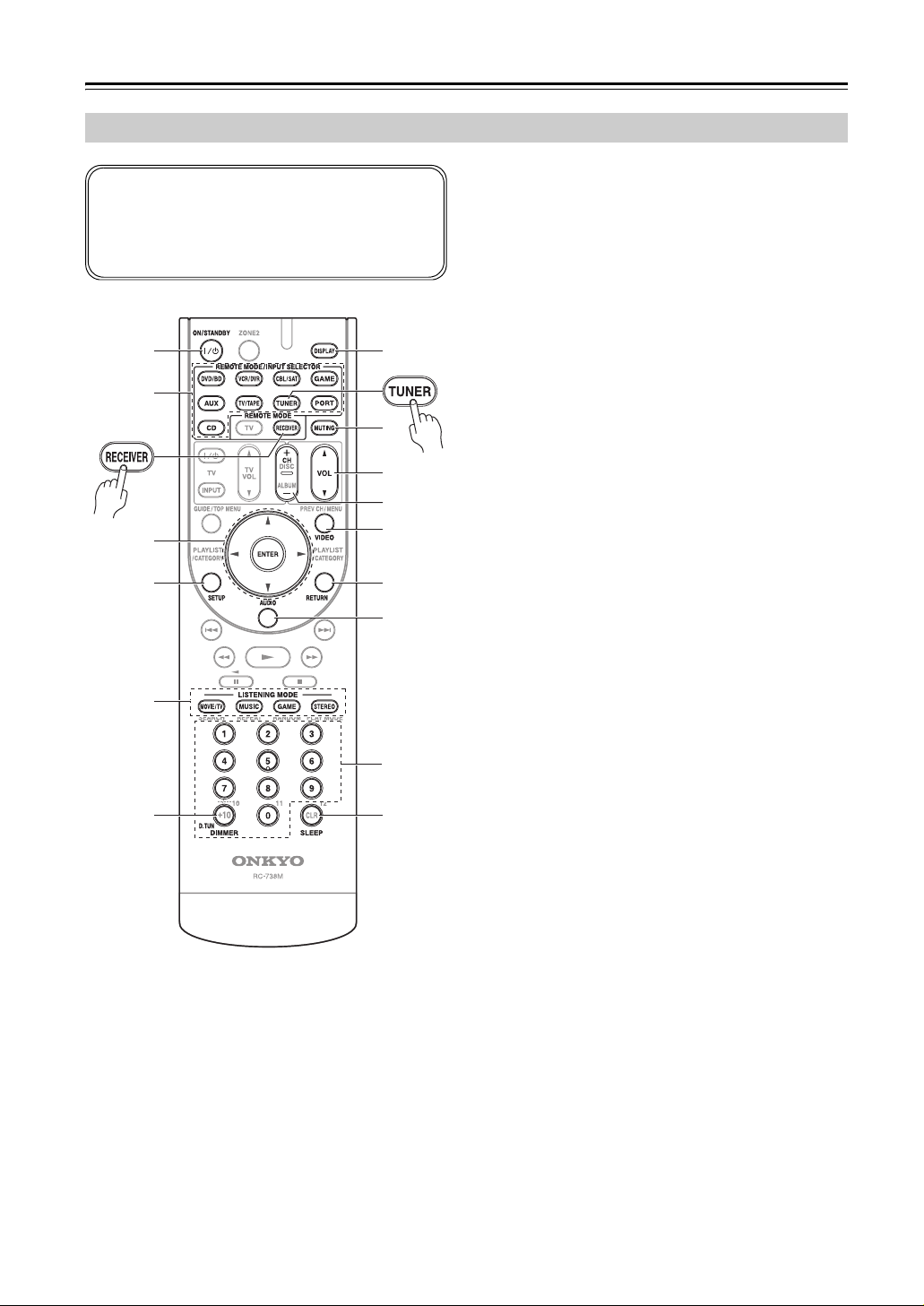
Remote Controller—Continued
Controlling the AV Receiver
To control the AV receiver, press the [RECEIVER]
button to select Receiver mode.
You can also use the remote controller to control your
DVD player, CD player, and other components.
See page 91 for more details.
a
g
3
b
h
i
4
1
c
d
j
k
l
e LISTENING MODE buttons (62)
Used to select the listening modes.
f DIMMER button (52)
Adjusts the display brightness.
g DISPLAY button (52)
Displays information about the current input source.
h MUTING button (53)
Mutes or unmutes the AV receiver.
i VOL [q]/[w] button (51)
Adjusts the volume of the AV receiver regardless of
the currently selected remote controller mode.
j VIDEO button (83)
Used to change video settings.
k RETURN button
Returns to the previous display when changing settings.
l AUDIO button (75)
Used to change audio settings.
When the “Audio TV Out” setting is set to “On”
(page 81), this button is disabled.
m SLEEP button (53)
Used with the Sleep function.
e
5
2
For detailed information, see the pages in parentheses.
a ON/STANDBY button (38)
Sets the AV receiver to On or Standby.
b REMOTE MODE/INPUT SELECTOR buttons
(51, 93–99)
Selects the remote controller modes and the input
sources.
c Arrow [q]/[w]/[e]/[r] and ENTER buttons
Used to select and adjust settings.
d SETUP button
Used to change settings.
mf
■ Controlling the tuner
To control the AV receiver’s tuner, press the [TUNER]
(or [RECEIVER]) button.
You can select AM or FM by pressing the [TUNER] button repeatedly.
1 Arrow [q]/[w] buttons
Used to tune into radio stations.
2 D.TUN button (54)
Selects the Direct tuning mode.
3 DISPLAY button
Displays information about the band, frequency,
preset number, and so on.
4 CH +/– button (55)
Used to select radio presets.
5 Number buttons (54)
Used to select radio stations directly in the Direct
tuning mode. Also you can select a preset directly.
Note:
An Onkyo cassette recorder connected via u can also
be controlled in Receiver mode (see page 99).
14
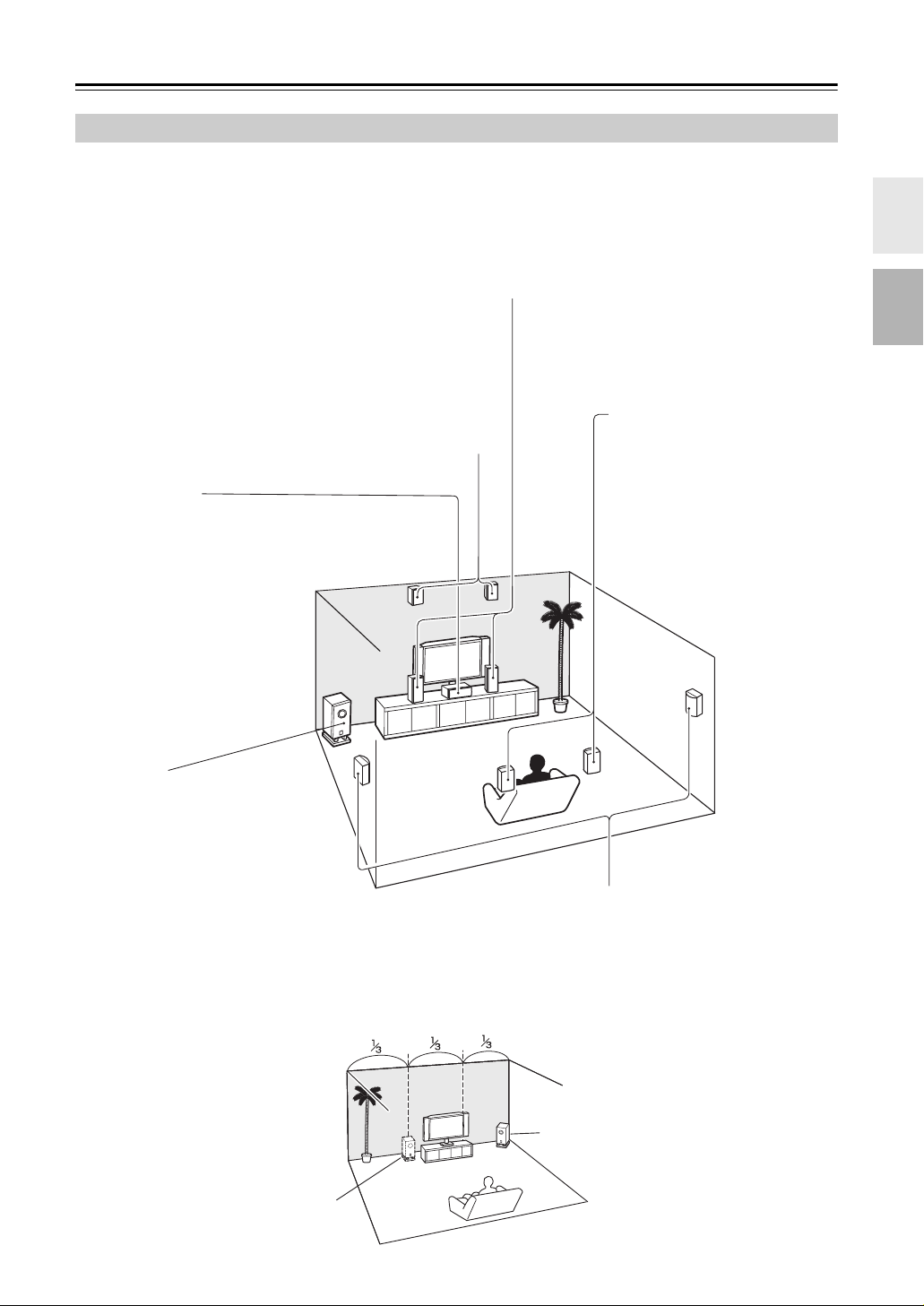
About Home Theater
Enjoying Home Theater
Thanks to the AV receiver’s superb capabilities, you can enjoy surround sound with a real sense of movement in your
own home—just like being in a movie theater or concert hall. With DVDs you can enjoy DTS and Dolby Digital. With
analog or digital TV, you can enjoy Dolby Pro Logic IIx, DTS Neo:6, or Onkyo’s original DSP listening modes.
Front left and right speakers
These output the overall sound. Their role in a home theater is to provide a solid
anchor for the sound image. They should be positioned facing the listener at about
ear level, and equidistant from the TV. Angle them inward so as to create a triangle,
with the listener at the apex.
Front high left and right speakers
These speakers are necessary to enjoy Dolby PLIIz Height, etc.
They enhance significantly the spatial experience.
Position them at least 3.3 feet (100 cm) above the front left and right
speakers (and as high as possible). Although it is acceptable to
place left and right at an angle slightly wider than the front left and
right speakers. Ideally they should be positioned directly above the
front left and right speakers.
Center speaker
This speaker enhances the
front left and right speakers,
making sound movements distinct and providing a full sound
image. In movies it’s used
mainly for dialog.
Position it close to your TV facing forward at about ear level, or
at the same height as the front
left and right speakers.
Surround back left and right
speakers
These speakers are necessary to
enjoy Dolby Digital EX, DTS-ES
Matrix, DTS-ES Discrete, etc. They
enhance the realism of surround
sound and improve sound localization behind the listener. Position
them behind the listener about 2–
3 feet (60–100 cm) above ear level.
Subwoofer
The subwoofer handles the bass sounds
of the LFE (Low-Frequency Effects)
channel. The volume and quality of the
bass output from your subwoofer will
depend on its position, the shape of your
listening room, and your listening position. In general, a good bass sound can
be obtained by installing the subwoofer in
a front corner, or at one-third the width of
the wall, as shown.
Tip: To find the best position for your subwoofer, while playing a movie or some
music with good bass, experiment by
placing your subwoofer at various positions within the room, and choose the one
that provides the most satisfying results.
1/3 of wall
position
Surround left and right speakers
These speakers are used for precise sound positioning and
to add realistic ambience.
Position them at the sides of the listener, or slightly behind,
about 2–3 feet (60–100 cm) above ear level. Ideally they
should be equidistant from the listener.
Corner
position
15
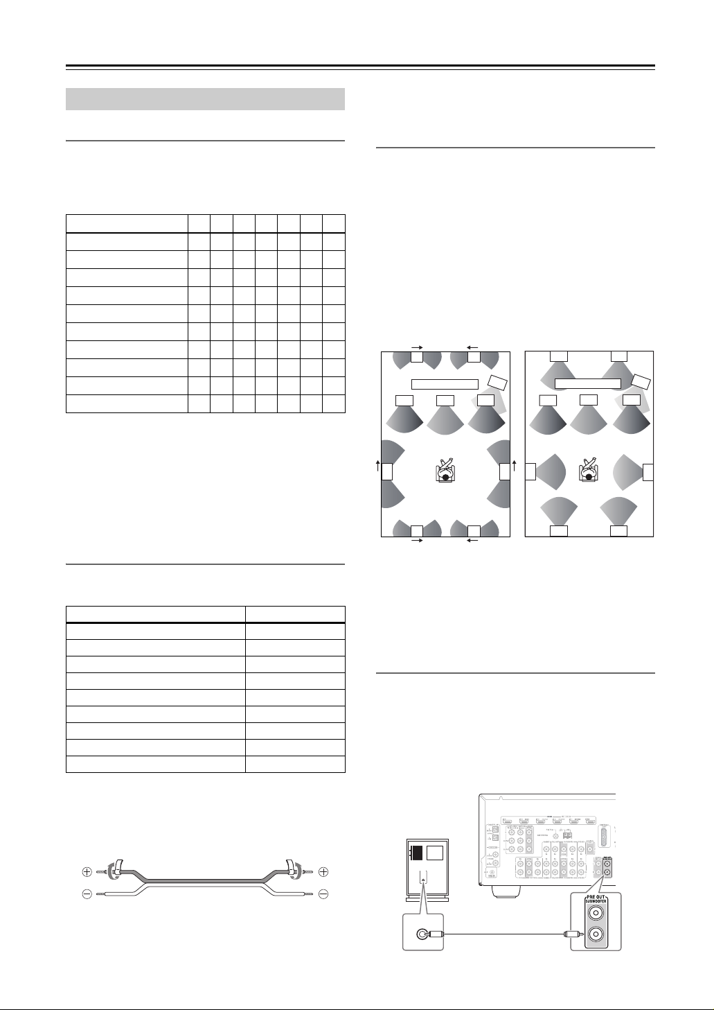
Connecting the AV Receiver
Connecting Your Speakers
Speaker Configuration
For 7.1-channel surround-sound playback, you need
seven speakers and a powered subwoofer.
The following table indicates the channels you should
use depending on the number of speakers that you have.
Number of speakers:2345677
Front left ✓✓✓✓✓✓✓
Front right ✓✓✓✓✓✓✓
Center ✓✓✓✓✓
Surround left ✓✓✓✓✓
Surround right ✓✓✓✓✓
Surround back* ✓
Surround back left ✓
Surround back right ✓
Front high left ✓
Front high right ✓
* If you’re using only one surround back speaker, connect it to the
SURR BACK L terminals.
No matter how many speakers you use, a powered subwoofer is recommended for a really powerful and solid
bass.
To get the best from your surround sound system, you
need to set the speaker settings. You can do this automatically (see page 46) or manually (see page 70).
Attaching the Speaker Labels
The AV receiver’s positive (+) speaker terminals are all
red (the negative (–) speaker terminals are all black).
Speaker Color
Front left, Zone 2 left White
Front right, Zone 2 right Red
Center Green
Surround left Blue
Surround right Gray
Surround back left Brown
Surround back right Tan
Front high left White
Front high right Red
The supplied speaker cable labels are also color-coded
and you should attach them to the positive (+) side of
each speaker cable in accordance with the above table.
Then all you need to do is to match the color of each
label to the corresponding speaker terminal.
• Do not insert the speaker code directly into the center
hole of the speaker terminal.
Using Dipole Speakers
You can use dipole speakers for the surround left and
right, surround back left and right and front high left and
right speakers. Dipole speakers output the same sound in
two directions.
Dipole speakers typically have an arrow printed on them
to indicate how they should be positioned. The surround
left and right dipole speakers should be positioned so
that their arrows point toward the TV/screen, while the
surround back left and right and front high left and right
dipole speakers should be positioned so that their arrows
point toward each other, as shown.
Dipole speakers
9 10
TV/screen TV/screen
2
5
7 8
1. Subwoofer
2. Front left speaker
3. Center speaker
4. Front right speaker
5. Surround left speaker
6. Surround right speaker
4
3
1
6
Normal speakers
9 10
1
3
2
5
7 8
7. Surround back left
speaker
8. Surround back right
speaker
9. Front high left speaker
10.Front high right speaker
4
Connecting a Powered Subwoofer
Using a suitable cable, connect the AV receiver’s PRE
OUT: SUBWOOFER to an input on your powered subwoofer, as shown. If your subwoofer is unpowered and
you’re using an external amplifier, connect the PRE
OUT: SUBWOOFER to an input on the amp.
The same signal is output from each jack.
Powered
subwoofer
6
For North American model
• If you are using banana plugs, tighten the speaker terminal before inserting the banana plug.
16
LINE INPUT
LINE INPUT
Connecting the AV Receiver—Continued
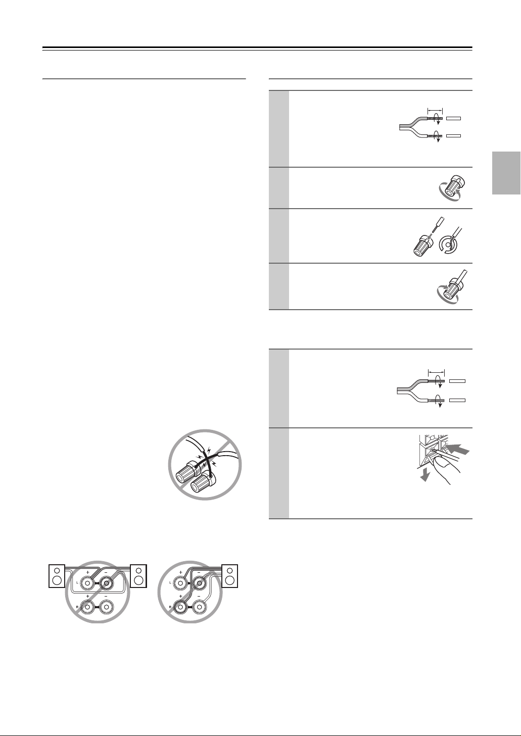
Speaker Connection Precautions
Read the following before connecting your speakers:
• North American/Taiwan models: You can connect
speakers with an impedance of between 6 and 16
ohms. If you use speakers with a lower impedance,
and use the amplifier at high volume levels for a long
period of time, the built-in amp protection circuit may
be activated.
• Other models: You can connect speakers with an
impedance of between 4 and 16 ohms. If the impedance of any of the connected speakers is 4 ohms or
more, but less than 6 ohms, be sure to set the minimum
speaker impedance to “4ohms” (see page 43). If you
use speakers with a lower impedance, and use the
amplifier at high volume levels for a long period of
time, the built-in protection circuit may be activated.
• Disconnect the power cord from the wall outlet before
making any connections.
• Read the instructions supplied with your speakers.
• Pay close attention to speaker wiring polarity. In other
words, connect positive (+) terminals only to positive
(+) terminals, and negative (–) terminals only to negative (–) terminals. If you get them the wrong way
around, the sound will be out of phase and will sound
unnatural.
• Unnecessarily long, or very thin speaker cables may
affect the sound quality and should be avoided.
• If you use 4 or 5 speakers, connect each of the two
surround speakers to the SURR L/R terminals. Do not
connect them to the SURR BACK L/R or FRONT
HIGH L/R terminals.
• Be careful not to short the
positive and negative wires.
Doing so may damage the AV
receiver.
• Make sure the metal core of
the wire does not have contact
with the AV receiver’s rear
panel. Doing so may damage the AV receiver.
• Don’t connect more than one cable to each speaker
terminal. Doing so may damage the AV receiver.
• Don’t connect one speaker to several terminals.
Connecting the Speaker Cables
Strip 1/2″-5/8″ (12-
1
15 mm) of insulation
from the ends of the
speaker cables, and
twist the bare wires
tightly, as shown.
Unscrew the terminal.
2
Fully insert the bare
3
wires.
Screw the terminal tight.
4
FRONT HIGH L/R, ZONE 2 L/R
(North American/Taiwan models)
Strip 3/8″-1/2″ (10-
1
12 mm) of insulation
from the ends of the
speaker cables, and
twist the bare wires
tightly, as shown.
While pressing the lever,
2
insert the wire into the
hole, and then release the
lever.
Make sure that the
terminals are gripping the bare wires, not
the insulation.
1/2″-5/8″(12-15 mm)
3/8″-1/2″(10-12 mm)
17
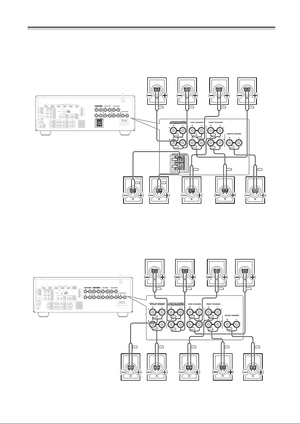
Connecting the AV Receiver—Continued
The following illustration shows which speaker should be connected to each pair of terminals. If you’re using only one
surround back speaker, connect it to the left (L) SURR BACK SPEAKERS terminals.
■ North American/Taiwan models
Surround
back left
speaker
Surround
back right
speaker
Surround
left
speaker
Surround
right
speaker
■ Other models
Front high
left
speaker
Front high
right
speaker
Surround
back left
speaker
Front left
speaker
Surround
back right
speaker
Front right
speaker
Surround
left
speaker
Center
speaker
Surround
right
speaker
18
Front high
left
speaker
Front high
right
speaker
Front left
speaker
Front right
speaker
Center
speaker
Connecting the AV Receiver—Continued
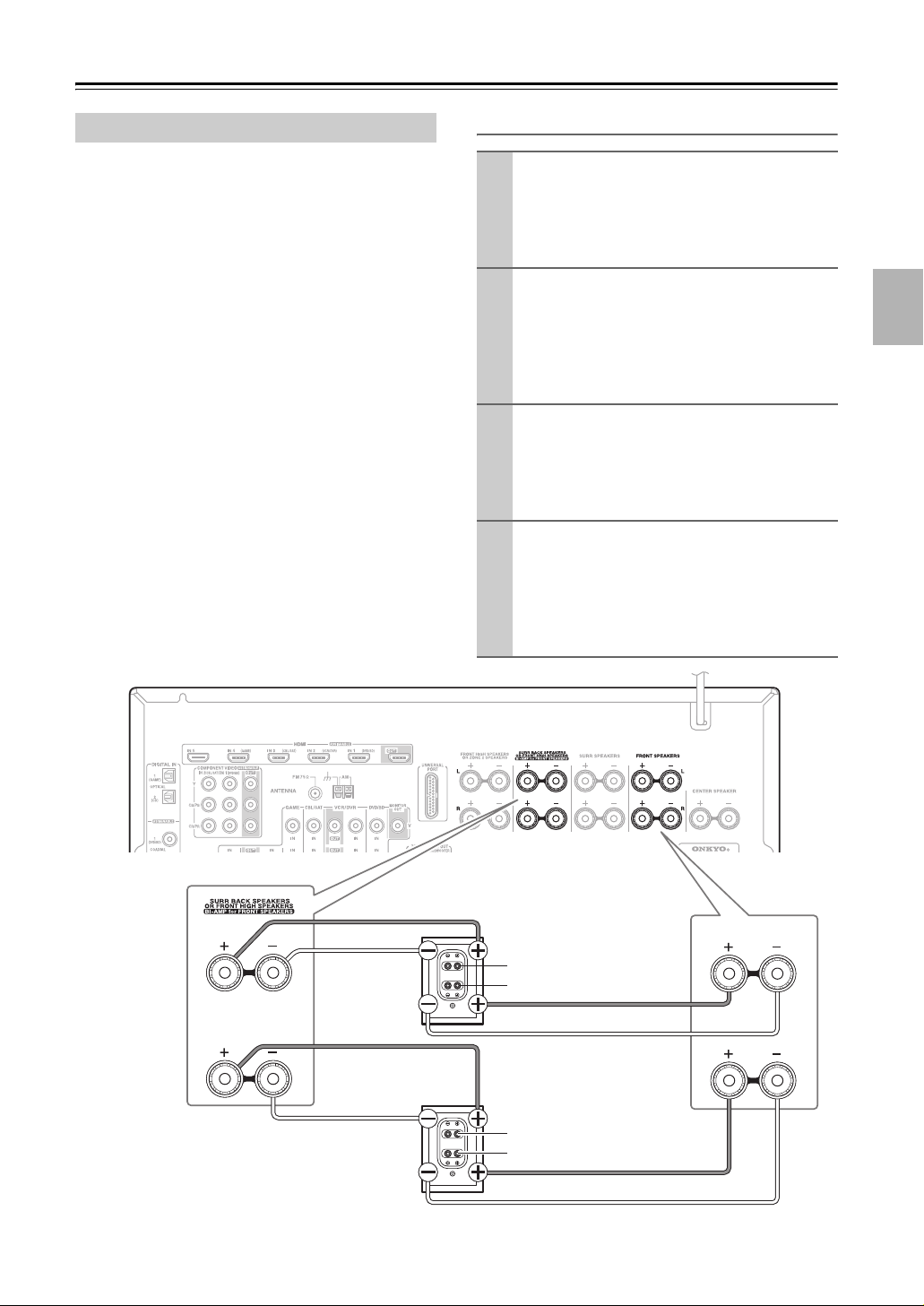
Bi-amping the Front Speakers
The FRONT L/R and SURR BACK L/R terminal posts
can be used with front speakers and surround back
speakers respectively, or bi-amped to provide separate
tweeter and woofer feeds for a pair of front speakers that
support bi-amping, providing improved bass and treble
performance.
• When bi-amping is used, the AV receiver is able to
drive up to 5.1 speakers in the main room.
• For bi-amping, the FRONT L/R terminal posts connect to the front speakers’ woofer terminals. And the
SURR BACK L/R terminal posts connect to the front
speakers’ tweeter terminals.
• Once you’ve completed the bi-amping connections
shown below and turned on the AV receiver, you must
set the “Speaker Type” setting to “Bi-Amp” to enable
biamping (see page 43).
Important:
• When making the bi-amping connections, be sure
to remove the jumper bars that link the speakers’
tweeter (high) and woofer (low) terminals.
• Bi-amping can only be used with speakers that support
bi-amping. Refer to your speaker manual.
Bi-amping Speaker Hookup
Connect the AV receiver’s FRONT R positive (+)
1
terminal to the right speaker’s positive (+) Woofer
(low) terminal. And connect the AV receiver’s
FRONT R negative (–) terminal to the right
speaker’s negative (–) Woofer (low) terminal.
Connect the AV receiver’s SURR BACK R posi-
2
tive (+) terminal to the right speaker’s positive (+)
Tweeter (high) terminal. And connect the AV
receiver’s SURR BACK R negative (–) terminal
to the right speaker’s negative (–) Tweeter (high)
terminal.
Connect the AV receiver’s FRONT L positive (+)
3
terminal to the left speaker’s positive (+) Woofer
(low) terminal. And connect the AV receiver’s
FRONT L negative (–) terminal to the left
speaker’s negative (–) Woofer (low) terminal.
Connect the AV receiver’s SURR BACK L posi-
4
tive (+) terminal to the left speaker’s positive (+)
Tweeter (high) terminal. And connect the AV
receiver’s SURR BACK L negative (–) terminal to
the left speaker’s negative (–) Tweeter (high) terminal.
L
Left speaker
R
Right speaker
Tweeter (high)
Woofer (low)
Tweeter (high)
Woofer (low)
FRONT SPEAKERS
L
R
19
Connecting the AV Receiver—Continued
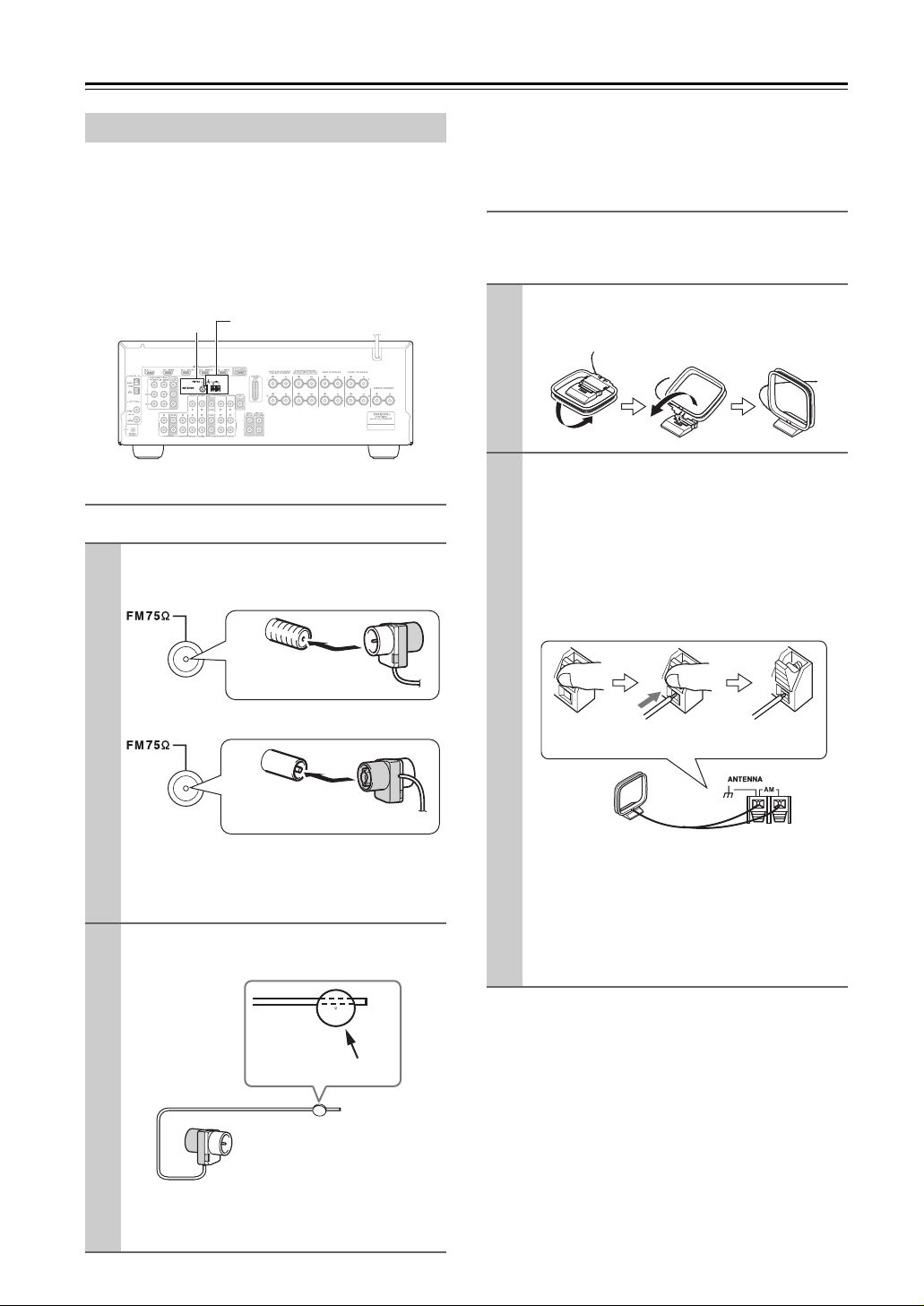
Connecting Antenna
This section explains how to connect the supplied indoor
FM antenna and AM loop antenna, and how to connect
commercially available outdoor FM and AM antennas.
The AV Receiver won’t pick up any radio signals without any antenna connected, so you must connect the
antenna to use the tuner.
FM ANTENNA
jack
Connecting the Indoor FM Antenna
The supplied indoor FM antenna is for indoor use only.
Attach the FM antenna, as shown.
1
■ North American/Taiwan models
AM ANTENNA push terminals
If you cannot achieve good reception with the supplied
indoor FM antenna, try a commercially available outdoor FM antenna instead (see page 21).
Connecting the AM Loop Antenna
The supplied indoor AM loop antenna is for indoor use
only.
Assemble the AM loop antenna, inserting
1
the tabs into the base, as shown.
Connect both wires of the AM loop
2
antenna to the AM antenna push terminals, as shown.
(The antenna’s wires are not polarity sensitive, so
they can be connected either way around.)
Make sure that the wires are attached securely and
that the push terminals are gripping the bare
wires, not the insulation.
Insert the plug fully
into the jack.
■ Other models
Insert the plug fully
into the jack.
Once your AV Receiver is ready for use, you’ll
need to tune into an FM radio station and adjust
the position of the FM antenna to achieve the best
possible reception.
Use thumbtacks or something similar to
2
fix the FM antenna into position.
Thumbtacks, etc.
Push Insert wire Release
Once your AV Receiver is ready for use, you’ll
need to tune into an AM radio station and adjust
the position of the AM antenna to achieve the best
possible reception.
Keep the antenna as far away as possible from
your AV Receiver, TV, speaker cables, and power
cords.
If you cannot achieve good reception with the supplied
indoor AM loop antenna, try using it with a commercially available outdoor AM antenna (see page 21).
20
Caution:
Be careful that you don’t injure yourself when
using thumbtacks.
Connecting the AV Receiver—Continued
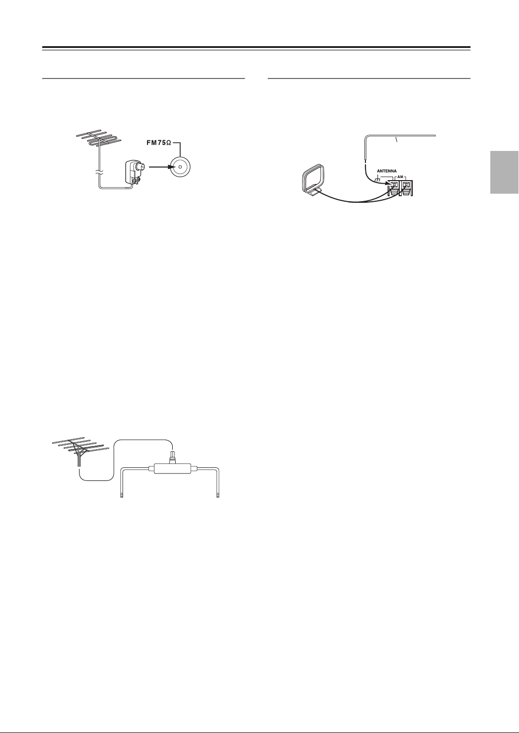
Connecting an Outdoor FM Antenna
If you cannot achieve good reception with the supplied
indoor FM antenna, try a commercially available outdoor FM antenna instead.
Notes:
• Outdoor FM antennas work best outside, but usable
results can sometimes be obtained when installed in an
attic or loft.
• For best results, install the outdoor FM antenna well
away from tall buildings, preferably with a clear line
of sight to your local FM transmitter.
• Outdoor antenna should be located away from possible noise sources, such as neon signs, busy roads, etc.
• For safety reasons, outdoor antenna should be situated
well away from power lines and other high-voltage
equipment.
• Outdoor antenna must be grounded in accordance
with local regulations to prevent electrical shock hazards.
Connecting an Outdoor AM Antenna
If good reception cannot be achieved using the supplied
AM loop antenna, an outdoor AM antenna can be used
in addition to the loop antenna, as shown.
Outdoor antenna
Insulated antenna cable
AM loop antenna
Outdoor AM antennas work best when installed outside
horizontally, but good results can sometimes be obtained
indoors by mounting horizontally above a window. Note
that the AM loop antenna should be left connected.
Outdoor antenna must be grounded in accordance with
local regulations to prevent electrical shock hazards.
■ Using a TV/FM Antenna Splitter
It’s best not to use the same antenna for both FM and TV
reception, as this can cause interference problems. If circumstances demand it, use a TV/FM antenna splitter, as
shown.
TV/FM antenna splitter
To AV Receiver To TV (or VCR)
21
Connecting the AV Receiver—Continued
About AV Connections
• Before making any AV connections, read the manuals
supplied with your other AV components.
• Don’t connect the power cord until you’ve completed
and double-checked all AV connections.
Optical Digital Jacks
The AV receiver’s optical digital jacks have shutter-type
covers that open when an optical plug is inserted and
close when it’s removed. Push plugs in all the way.
Caution:
To prevent shutter damage, hold the optical plug straight
when inserting and removing.
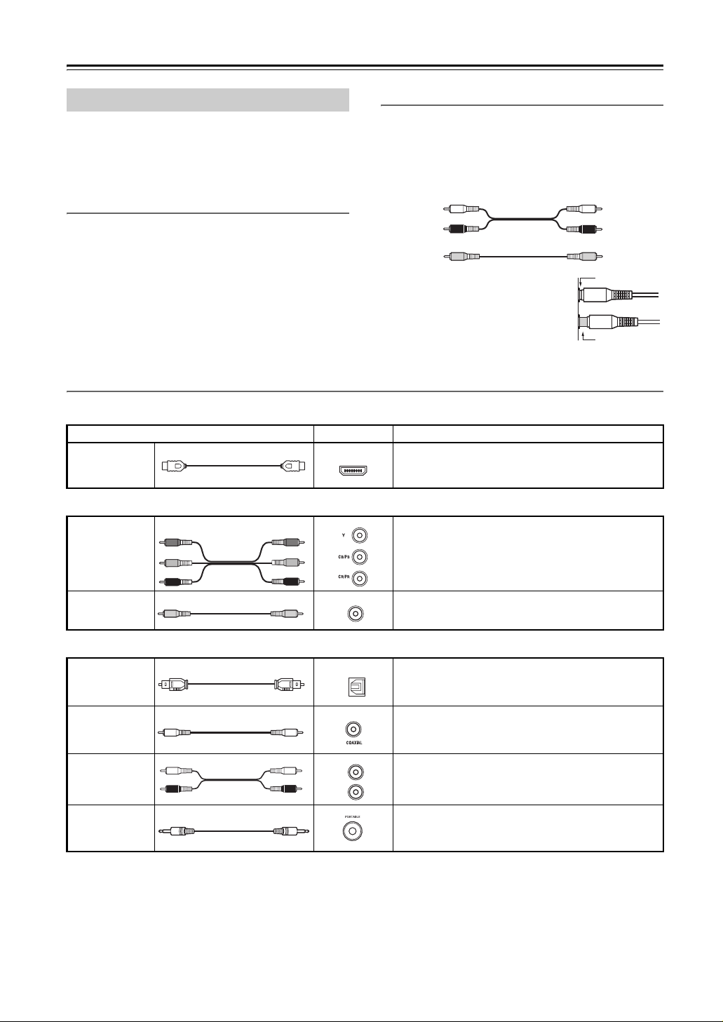
AV Cables & Jacks
Video / Audio
Cable Jack Description
HDMI
AV Connection Color Coding
RCA-type AV connections are usually color-coded: red,
white, and yellow. Use red plugs to connect right-channel audio inputs and outputs (typically labeled “R”). Use
white plugs to connect left-channel audio inputs and outputs (typically labeled “L”). And use yellow plugs to
connect composite video inputs and outputs.
Left (white)
Right (red) Right (red)
(Yellow)
• Push plugs in all the way to make
good connections (loose connections can cause noise or malfunctions).
• To prevent interference, keep
audio and video cables away from
power cords and speaker cables.
HDMI
HDMI connections can carry uncompressed standard- or high-definition digital video and audio and
offer the best picture and sound quality.
Analog audio
Composite video
Left (white)
(Yellow)
Right!
Wrong!
Video
Component
video cable
Composite
video cable
Audio
Optical digital
audio cable
Coaxial digital
audio cable
Analog audio
cable (RCA)
Stereo mini
plug cable
Y
B/CB
P
PR/CR
P
B/CB
PR/CR
Y
The AV receiver does not support SCART plugs.
V
OPTICAL
L
R
Component video separates the luminance (Y) and
color difference signals (PR, PB), providing the best
picture quality (some TV manufacturers label their
component video sockets slightly differently).
Composite video is commonly used on TVs, VCRs,
and other video equipment.
Offers the best sound quality and allows you to
enjoy surround sound (e.g., Dolby Digital, DTS).
The audio quality is the same as for coaxial.
Offers the best sound quality and allows you to
enjoy surround sound (e.g., Dolby Digital, DTS).
The audio quality is the same as for optical.
This cable carries analog audio. It’s the most common connection format for analog audio, and can be
found on virtually all AV components.
This cable carries analog audio.
22
Connecting the AV Receiver—Continued
Connecting Components with HDMI
About HDMI
Designed to meet the increased demands of digital TV, HDMI (High Definition Multimedia Interface) is a new digital
interface standard for connecting TVs, projectors, DVD players, set-top boxes, and other video components. Until now,
several separate video and audio cables have been required to connect AV components. With HDMI, a single cable can
carry control signals, digital video, and up to eight channels of digital audio (2-channel PCM, multichannel digital
audio, and multichannel PCM).
The HDMI video stream (i.e., video signal) is compatible with DVI (Digital Visual Interface)*1, so TVs and displays
with a DVI input can be connected by using an HDMI-to-DVI adapter cable. (This may not work with some TVs and
displays, resulting in no picture.)
The AV receiver uses HDCP (High-bandwidth Digital Content Protection)
can display the picture.
The AV receiver’s HDMI interface is based on the following standard:
Repeater System, Deep Color, Lip Sync, DTS-HD Master Audio, DTS-HD High Resolution Audio, Dolby TrueHD,
Dolby Digital Plus, DSD, and Multichannel PCM
Supported Audio Formats
• 2-channel linear PCM (32–192 kHz, 16/20/24 bit)
• Multichannel linear PCM (up to 7.1 ch, 32–192 kHz, 16/20/24 bit)
• Bitstream (DSD, Dolby Digital, Dolby Digital Plus, Dolby TrueHD, DTS, DTS-HD High Resolution Audio, DTSHD Master Audio)
Your DVD player must also support HDMI output of the above audio formats.
*2,
so only HDCP-compatible components
About Copyright Protection
The AV receiver supports HDCP (High-bandwidth Digital Content Protection)*2, a copy-protection system for digital
video signals. Other devices connected to the AV receiver via HDMI must also support HDCP.
Commercially available HDMI cables (supplied with some components) should be used to connect the AV receiver’s
HDMI OUT to the HDMI input on your TV or projector.
■ Onkyo for System Control
, which stands for Remote Interactive over HDMI, is the name of the system control function found on Onkyo
components. The AV receiver can be used with CEC (Consumer Electronics Control), which allows system control over
HDMI and is part of the HDMI standard. CEC provides interoperability between various components, however, operation with components other than -compatible components cannot be guaranteed.
• Set “HDMI Control (RIHD)” to “On” (page 82).
• See “Controlling a TV” (page 93) and “Controlling a DVD Player, or DVD Recorder” (page 94) for operation.
Note:
Do not connect the -compatible component more than the following number to the HDMI input terminal so
that the linked operations work properly.
• DVD/BD player is up to three.
• DVD/BD recorder is up to three.
• Cable/Satellite Set-top box is up to four.
Do not connect the AV receiver to the other AV receiver /AV amplifier via HDMI.
When the -compatible component more than the above-mentioned is connected, the linked operations are not
guaranteed.
*1 DVI (Digital Visual Interface): The digital display interface standard set by the DDWG
*2 HDCP (High-bandwidth Digital Content Protection): The video encryption technology developed by Intel for HDMI/DVI. It’s designed to
protect video content and requires a HDCP-compatible device to display the encrypted video.
*3 DDWG (Digital Display Working Group): Lead by Intel, Compaq, Fujitsu, Hewlett Packard, IBM, NEC, and Silicon Image, this open
industry group’s objective is to address the industry’s requirements for a digital connectivity specification for high-performance PCs and
digital displays.
*3
in 1999.
23
Connecting the AV Receiver—Continued
Making HDMI Connections
Step 1:
Use HDMI cables to connect the AV receiver’s HDMI jacks to your HDMI-compatible Blu-ray player/DVD player,
TV, projector, and so on.
Step 2:
Assign each HDMI IN to an input selector in the HDMI Input Setup (see page 40).
■ Video Signals
Digital video signals received by the HDMI IN jacks are normally output by the HDMI OUT for display on your TV.
Composite video and component video sources can be upconverted for the HDMI output. See “Video Connection Formats” on page 25 for more information.
■ Audio Signals
Digital audio signals received by the HDMI IN jacks are output by the speakers and headphones connected to the AV
receiver. Normally, they are not output by the HDMI OUT, unless the “Audio TV Out” setting is set to “On” (see
page 81).
Hint!
To listen to audio received by the HDMI IN jacks through your TV’s speakers, set the “Audio TV Out”
setting to “On” (see page 81), and set your DVD player’s HDMI audio output setting to PCM.
Blu-ray player/DVD player
HDMI
IN
TV
HDMI OUT
HD camcorder, etc
HDMI
OUT
HDMI HDMI
IN 1
(DVD/BD)
Notes:
• The HDMI video stream is compatible with DVI (Digital Visual Interface), so TVs and displays with a DVI input can
be connected by using an HDMI-to-DVI adapter cable. (Note that DVI connections only carry video, so you’ll need
to make a separate connection for audio.) However, reliable operation with such an adapter is not guaranteed. In
addition, video signals from a PC are not supported.
• When listening to an HDMI component through the AV receiver, set the HDMI component so that its video can be
seen on the TV screen (on the TV, select the input of the HDMI component connected to the AV receiver). If the TV
power is off or the TV is set to another input source, this may result in no sound from the AV receiver or the sound
may be cut off.
• When the “Audio TV Out” setting is set to “On” (see page 81), or “TV Control” is set to “On” (see page 82) and
you’re listening through your TV’s speakers, if you turn up the AV receiver volume control, the sound will be output
by the AV receiver’s speakers. To stop the AV receiver’s speakers producing sound, change the settings, change your
TV’s settings, or turn down the AV receiver’s volume.
• The HDMI audio signal (sampling rate, bit length, etc.) may be restricted by the connected source component. If the
picture is poor or there’s no sound from a component connected via HDMI, check its setup. Refer to the connected
component’s instruction manual for details.
24
Connecting the AV Receiver—Continued
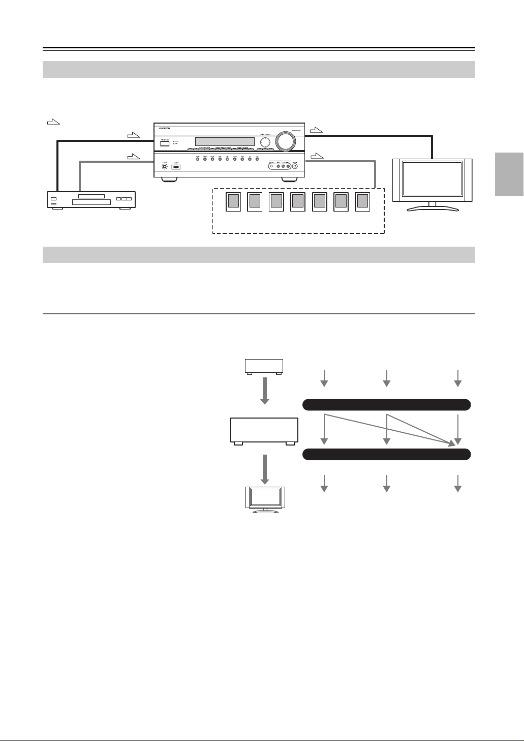
Connecting Both Audio & Video
By connecting both the audio and video outputs of your DVD player and other AV components to the AV receiver, you
can select both the audio and video simultaneously simply by selecting the appropriate input source on the AV receiver.
: Signal Flow
Video
Audio
DVD player, etc.
Speakers
(see page 18 for connection information)
Video
Audio
TV, projector,
etc.
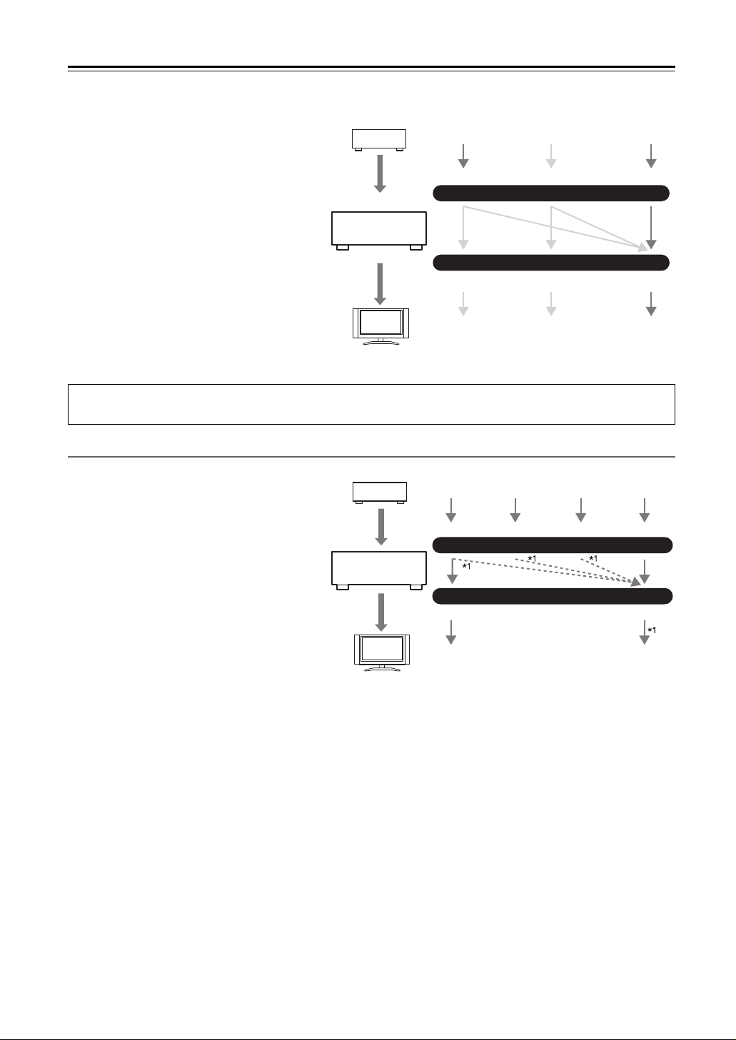
Which Connections Should I Use?
The AV receiver supports several connection formats for compatibility with a wide range of AV equipment. The format
you choose will depend on the formats supported by your other components. Use the following sections as a guide.
Video Connection Formats
Video equipment can be connected to the AV receiver by using any one of the following video connection formats:
composite video, component video, or HDMI, the latter offering the best picture quality.
Video input signals flow through the AV receiver
as shown, with composite video and component
video sources all being upconverted for the
HDMI output.
The composite video and component video outputs pass through their respective input signals as
they are.
When you connect audio equipment to an HDMI
or COMPONENT input, you must assign that
input to an input selector (see pages 40 and 41).
DVD player, etc.
AV receiver
Video Signal Flow Chart
Composite
Composite
Component
MONITOR OUT
Component
HDMI
IN
HDMI
TV, projector, etc.
25
Connecting the AV Receiver—Continued
■ Signal Selection
If signals are present at more than one input, the
inputs will be selected automatically in the following order of priority: HDMI, component
video, composite video.
However, for component video only, regardless
of whether a component video signal is actually
present, if a component video input is assigned to
the input selector, that component video input
will be selected. And if no component video
input is assigned to the input selector, this will be
interpreted as no component video signal being
present.
In the Signal Selection Example shown on the
right, video signals are present at both the HDMI
and composite video inputs, however, the HDMI
signal is automatically selected as the source and
video is output by the HDMI outputs.
The onscreen setup menus appear only on a TV that is connected to the HDMI OUT. If your TV is connected to the
MONITOR OUT V, or the COMPONENT VIDEO OUT, use the AV receiver’s display when changing settings.
Audio Connection Formats
DVD player, etc.
AV receiver
TV, projector, etc.
Signal Selection Example
Composite
Composite
Component
MONITOR OUT
Component
HDMI
IN
HDMI
Audio equipment can be connected to the AV
receiver by using any of the following audio con-
DVD player, etc.
Audio Signal Flow Chart
nection formats: analog, optical, coaxial, or
HDMI.
When choosing a connection format, bear in
mind that the AV receiver does not convert digital
input signals for analog line outputs and vice
Optical
IN
AV receiver
HDMICoaxial Analog
versa. For example, audio signals connected to
an optical or coaxial digital input are not output
by the analog TV/TAPE OUT.
TV, projector, etc.
*1 Depends on the “Audio TV Out” setting
(see page 81).
OUT
HDMI Analog
If signals are present at more than one input, the inputs will be selected automatically in the following order of priority:
HDMI, digital, analog.
26
Connecting the AV Receiver—Continued
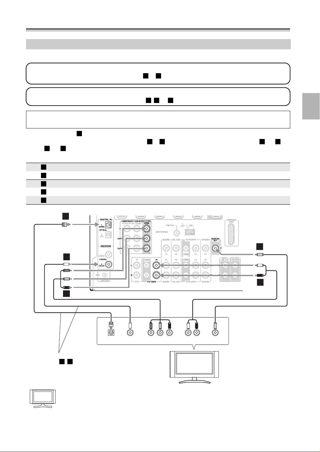
Connecting a TV or Projector
See “Connecting Components with HDMI” on page 23 for HDMI connection information.
Step 1: Video Connection
Choose a video connection that matches your TV ( or ), and then make the connection.
Step 2: Audio Connection
Choose an audio connection that matches your TV ( , , or ), and then make the connection.
The onscreen setup menus appear only on a TV that is connected to the HDMI OUT. If your TV is connected to the
MONITOR OUT V, or the COMPONENT VIDEO OUT, use the AV receiver’s display when changing settings.
A B
a b c
• With connection , you can listen to and record audio from your TV and listen in Zone 2.
• To enjoy Dolby Digital and DTS, use connection or . (To record or listen in Zone 2 as well, use and ,
or and .)
a c
a
b c a b
Connection AV receiver Signal flow TV
A
B
a
b
c
COMPONENT VIDEO OUT ⇒ Component video input
MONITOR OUT V ⇒ Composite video input
TV/TAPE IN L/R ⇐ Analog audio L/R output
DIGITAL IN COAXIAL 2 (CBL/SAT) ⇐ Digital coaxial output
DIGITAL IN OPTICAL 1 (GAME) ⇐ Digital optical output
c
BB
b
a
A
OPTICAL
OUT
OUT
Connect one or the other
Connection , must be assigned (see page 42)
Hint!
b c
If your TV has no audio outputs, connect an audio output from your VCR or cable or satellite receiver
to the AV receiver and use its tuner to listen to TV programs through the AV receiver (see pages 29 and
31).
P
YCOAXIAL
PB
COMPONENT VIDEO IN
R AUDIO
LR
OUT
TV, projector,
etc.
VIDEO
IN
27
Connecting the AV Receiver—Continued
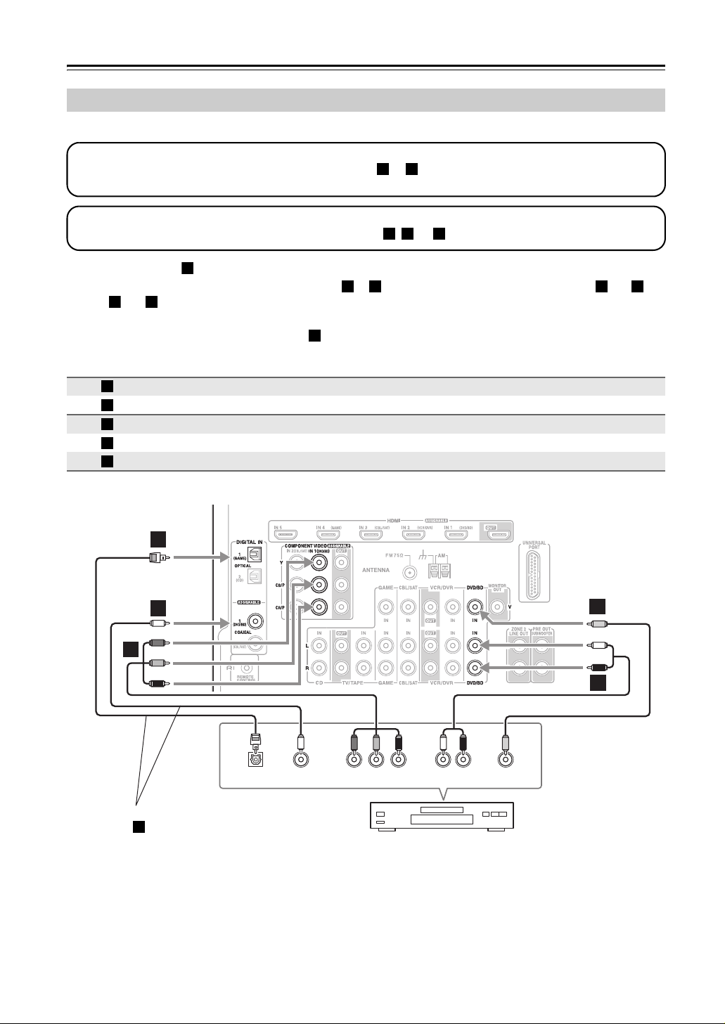
Connecting a DVD Player
See “Connecting Components with HDMI” on page 23 for HDMI connection information.
Step 1: Video Connection
Choose a video connection that matches your DVD player ( or ), and then make the connection.
You must connect the AV receiver to your TV via the same type of connection.
Step 2: Audio Connection
Choose an audio connection that matches your DVD player ( , , or ), and then make the connection.
A B
a b c
• With connection , you can listen to and record audio from a DVD and listen in Zone 2.
• To enjoy Dolby Digital and DTS, use connection or . (To record or listen in Zone 2 as well, use and ,
or and .)
a c
a
b c a b
• If your DVD player has main left and right outputs and multichannel left and right outputs, be sure to use the
main left and right outputs for connection .
Connection AV receiver Signal flow DVD player
A
B
a
b
c
COMPONENT VIDEO IN 1 (DVD/BD) ⇐ Component video output
DVD/BD IN V ⇐ Composite video output
DVD/BD IN L/R ⇐ Analog audio L/R output
DIGITAL IN COAXIAL 1 (DVD/BD) ⇐ Digital coaxial output
DIGITAL IN OPTICAL 1 (GAME) ⇐ Digital optical output
a
c
B
b
B
A
Connect one or the other
Connection must be assigned (see page 42)
c
28
OPTICAL
OUT
OUT
YCOAXIAL
PB
R AUDI O
COMPONENT VIDEO OUT
P
LR
OUT
DVD player
VIDEO
OUT
a
Connecting the AV Receiver—Continued
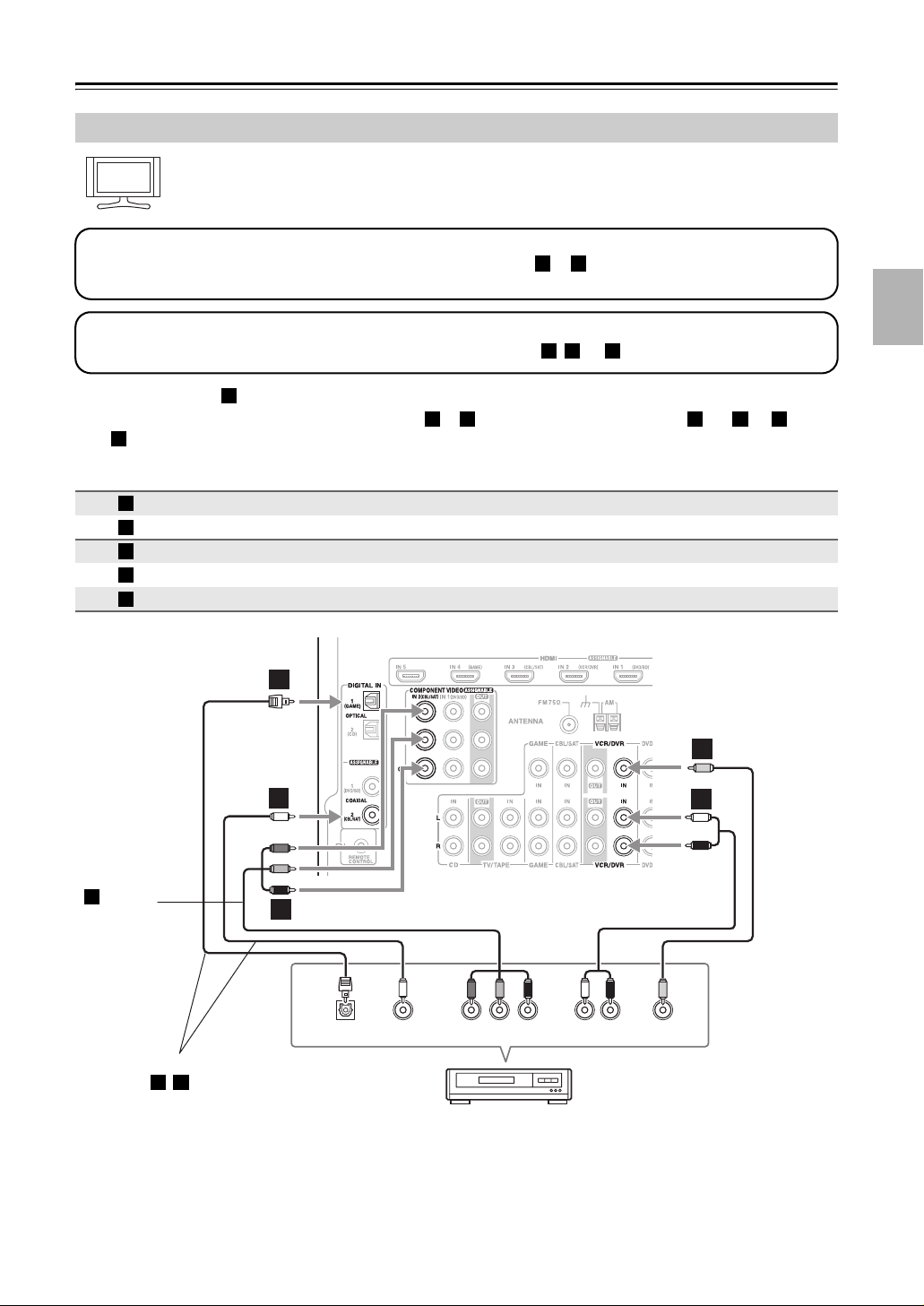
Connecting a VCR or DVD Recorder for Playback
Hint!
With this hookup, you can use your VCR’s tuner to listen to your favorite TV programs via the AV
receiver, useful if your TV has no audio outputs.
Step 1: Video Connection
Choose a video connection that matches your VCR or DVD recorder ( or
), and then make the connection. You
A B
must connect the AV receiver to your TV via the same type of connection.
Step 2: Audio Connection
Choose an audio connection that matches your VCR or DVD recorder ( , , or ), and then make the connection.
• With connection , you can listen to the VCR or DVD recorder even in Zone 2.
• To enjoy Dolby Digital and DTS, use connection or . (To listen in Zone 2 as well, use and , or and
.)
c
Connection AV receiver Signal flow VCR or DVD recorder
A
B
a
b
c
.
a
b c a b a
COMPONENT VIDEO IN 2 (CBL/SAT) ⇐ Component video output
VCR/DVR IN V ⇐ Composite video output
VCR/DVR IN L/R ⇐ Analog audio L/R output
DIGITAL IN COAXIAL 2 (CBL/SAT) ⇐ Digital coaxial output
DIGITAL IN OPTICAL 1 (GAME) ⇐ Digital optical output
a b c
c
b
Connection
must be
A
assigned
(see
page 41)
Connect one or the other
Connection , must be assigned (see page 42)
b c
A
OPTICAL
OUT
OUT
YCOAXIAL
PB
R AUDI O
COMPONENT VIDEO OUT
P
VCR,
DVD record er
LR
OUT
VIDEO
OUT
B
B
a
29
Connecting the AV Receiver—Continued
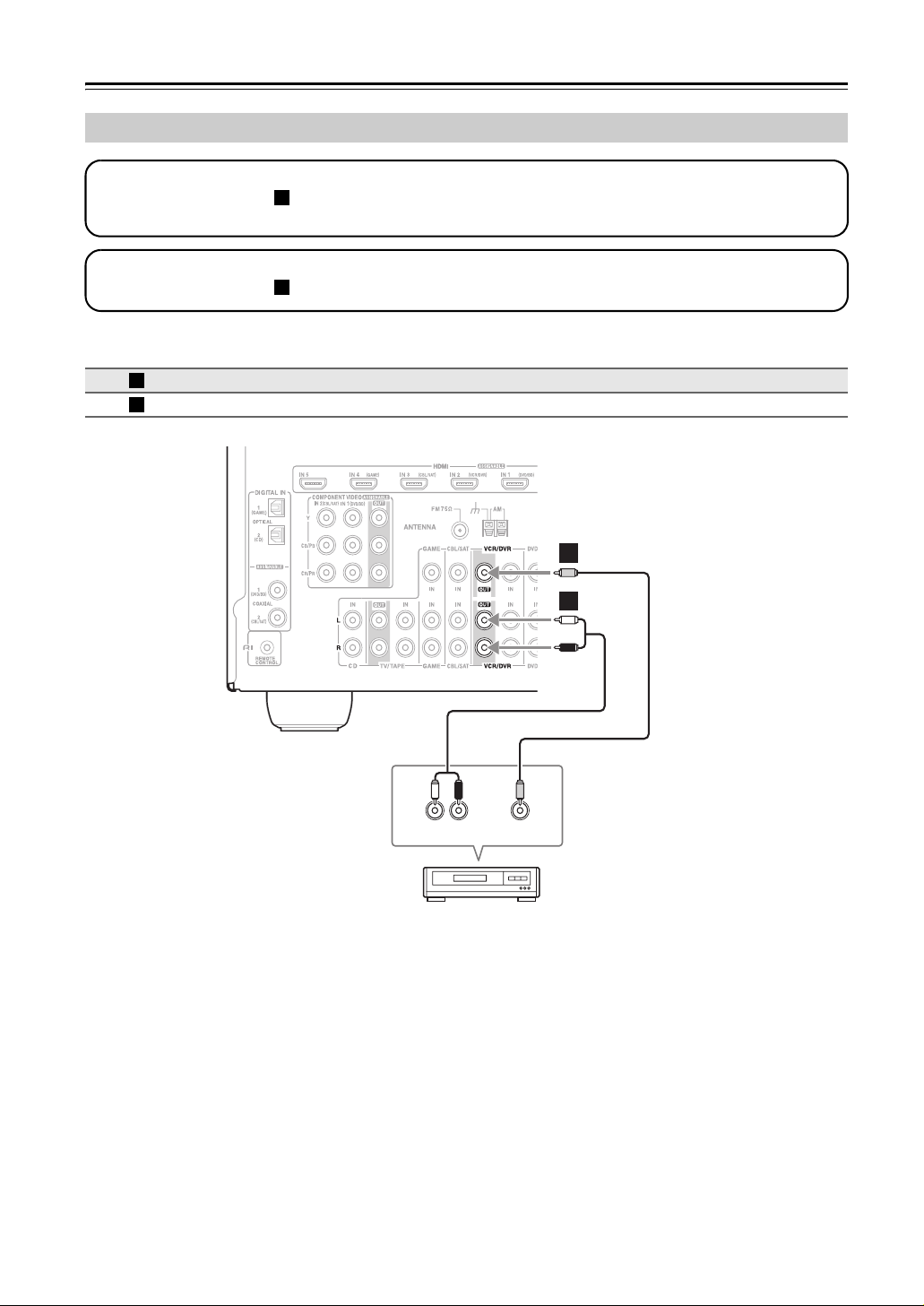
Connecting a VCR or DVD Recorder for Recording
Step 1: Video Connection
Make the video connection . The video source to be recorded must be connected to the AV receiver via the same
type of connection.
Step 2: Audio Connection
Make the audio connection .
Connection AV receiver Signal flow VCR or DVD recorder
A
a
A
a
VCR/DVR OUT V
VCR/DVR OUT L/R
⇒
⇒
A
B
Composite video input
Analog audio L/R input
a
LR
AUDIO
IN
VCR, DVD recorder
VIDEO
IN
Notes:
• The AV receiver must be turned on for recording. Recording is not possible while it’s in Standby mode.
• If you want to record directly from your TV or playback VCR to the recording VCR without going through the AV
receiver, connect the TV/VCR’s audio and video outputs directly to the recording VCR’s audio and video inputs. See
the manuals supplied with your TV and VCR for details.
• Video signals connected to composite video inputs can only be recorded via composite video outputs. If your
TV/VCR is connected to a composite video input, the recording VCR must be connected to a composite video output.
30
Loading…
- Главная
-
Onkyo
-
Аудио
-
TX-SR607
-
Руководство по эксплуатации
Вы можете бесплатно скачать Руководство по эксплуатации для Onkyo TX-SR607.
Также вы сможете прочесть онлайн этот документ без скачивания.
Скачать Руководство по эксплуатации для Onkyo TX-SR607
Тип файла
PDF
Размер
9.44 Mb
Кол-во страниц
108
Просмотров
5617
Вы не робот?
60
Скачать файл:
onkyo-tx-sr607-owner-s-manual.pdf
Читать онлайн Руководство по эксплуатации для Onkyo TX-SR607 (Страница 1)

Next →
- 1
- 2
- 3
- 4
- 5
- 6
- 7
- 8
- 9
- 10
- 11
- 12
- 13
- 14
- 15
- 16
- 17
- 18
- 19
- 20
- 21
- 22
- 23
- 24
- 25
- 26
- 27
- 28
- 29
- 30
- 31
- 32
- 33
- 34
- 35
- 36
- 37
- 38
- 39
- 40
- 41
- 42
- 43
- 44
- 45
- 46
- 47
- 48
- 49
- 50
- 51
- 52
- 53
- 54
- 55
- 56
- 57
- 58
- 59
- 60
- 61
- 62
- 63
- 64
- 65
- 66
- 67
- 68
- 69
- 70
- 71
- 72
- 73
- 74
- 75
- 76
- 77
- 78
- 79
- 80
- 81
- 82
- 83
- 84
- 85
- 86
- 87
- 88
- 89
- 90
- 91
- 92
- 93
- 94
- 95
- 96
- 97
- 98
- 99
- 100
- 101
- 102
- 103
- 104
- 105
- 106
- 107
- 108
Другие Аудио Onkyo TX-SR607
Топ Onkyo Аудио
-
TX-NR5010 Руководство пользователя
PDF файлов
6Просмотров
34917 -
A-5VL Руководство пользователя
PDF файлов
4Просмотров
7487 -
HT-S9400THX Руководство пользователя
PDF файлов
4Просмотров
15720 -
A-9070 Руководство пользователя
PDF файлов
4Просмотров
21241 -
TX-8050 Руководство пользователя
PDF файлов
4Просмотров
10819 -
BD-SP809 Руководство пользователя
PDF файлов
4Просмотров
18060
Ранее вы смотрели
Производители
Baratza
BBQ Pro
Becker Designed
Crate Amplifiers
Galileo
Hitachi
Polk Audio
Quer
Sonoro
ViewSonic
Типы устройств
Сварочные системы
Портативные радиостанции
Аксессуары для мобильных телефонов
Звуковые карты
Аккумуляторные дисковые (циркулярные) пилы
Фанкойлы (Вентиляторные доводчики)
Автомобильные инструменты
Игрушки
Платежные терминалы
Настенные обогреватели
Устройства
BT 3010 Executive
Fundex Games 3840
Honda 1988 NH80
LG HT33S
Linak TWINDRIVE HB22
Omron Healthcare INTELLISENSE BP755
Silvercrest KH 2159
Sony SRS-A3
Troy-Bilt CSV 070 Chipper Shredder Vac
freeuserguide.ru
About Us
Contacts
Disclamers
Privacy Policy
Эта страница полезна для вас? Поделитесь ссылкой:
Русский
- Bedienungsanleitung Onkyo TX-SR607
- Onkyo TX-SR607 User Manual
- Manual Usuario Onkyo TX-SR607
- Mode d’emploi Onkyo TX-SR607
- Istruzioni Onkyo TX-SR607
- инструкция Onkyo TX-SR607
- Onkyo TX-SR607の取扱説明書
- Handleiding Onkyo TX-SR607
- Manual de uso Onkyo TX-SR607
Вам нужна инструкция? Мы поможем Вам ее найти и сэкономить Ваше время.
- 2 stron
- 1.19 mb
Изделие Onkyo TX-SR607, а также другие, которыми Вы пользуетесь ежедневно, наверняка вы получили в комплекте с инструкцией обслуживания. Из опыта наших пользователей мы знаем, что большинство из Вас не уделили этому особого внимания. Большая часть инструкций, сразу же после покупки попадает в корзину для мусора вместе с коробкой — это ошибка. Ознакомьтесь с информацией, касающейся инструкции Onkyo TX-SR607, которая поможет Вам в будущем сэкономить нервы и избежать головной боли.
Важная подсказка — не забывайте хотя бы раз прочитать инструкцию Onkyo TX-SR607
Если вы не хотите каждый раз читать информационные брошюры, касающиеся, тех или Onkyo TX-SR607 иных изделий, достаточно, прочитать их раз — сразу же после покупки устройства. Вы получите основное знания, касающиеся поддержания изделия Onkyo TX-SR607 в хорошем эксплуатационном состоянии, так, чтобы без проблем достигнуть его планируемого цикла работы. Затем инструкцию можно отложить на полку и вернуться к ней только в случае, если вы не уверены, правильно ли проводится техобслуживание изделия. Правильный уход является необходимым элементом Вашего удовольствия Onkyo TX-SR607.
Раз в году пересмотрите шкафчик, в котором держите инструкции для всех устройств, — выбросите те, которыми вы уже не пользуетесься. Это поможет Вам сохранять порядок в своей домашней базе инструкций обслуживания.
Summary of Contents for Onkyo TX-SR607
Что находится в инструкции Onkyo TX-SR607? Почему стоит ее прочитать?
- Гарантия и подробности, касающиеся техобслуживания изделия
Хорошей идеей будет прикрепить чек к странице инструкции. Если что-то плохое случится во время использования Onkyo TX-SR607, у вас будет комплект документов, необходимый для гарантийного ремонта. В этой части инструкции вы найдете информацию об авторизованных сервисных центрахOnkyo TX-SR607 а также, как самостоятельно правильно ухаживать за оборудованием — так, чтобы не потерять гарантийных прав. - Указания по монтажу и Setup
Не терять нервов и времени на самостоятельную попытку установки и первого запуска изделия. Воспользуйтесь рекомендациями производителя Onkyo TX-SR607 чтобы правильно запустить изделие, без лишнего риска повреждения оборудования. - Информация, касающаяся дополнительных запчастей (входящих в комплект а также являющихся опцией)
Пересматривая эту часть документа вы сможете проверить, доставлен ли ваш Onkyo TX-SR607 с полним комплектом аксессуаров. Вы также сможете узнать, какие дополнительные запчасти или аксессуары для Onkyo TX-SR607 Вы сможете найти и докупить к своему устройству. - Troubleshooting
Самые частые проблемы, касающиеся Onkyo TX-SR607 и методы их решения. Это очень полезная часть руководства по обслуживанию — она позволит Вам сэкономить много времени на поиск решений. 90% проблем с Onkyo TX-SR607 повторяется у многих пользователей. - Требования, касающиеся питания и энергетический класс
Информация, касающаяся количества потребляемой энергии, а также рекомендации, касающиеся установки и питания Onkyo TX-SR607. Прочитайте, чтобы оптимально пользоваться Onkyo TX-SR607 и не использовать большего количества ресурсов, нежели это необходимо для правильной работы изделия. - Специальные функции Onkyo TX-SR607
Здесь вы можешь узнать, как персонализировать изделие Onkyo TX-SR607. Вы узнаете, какие дополнительные функции могут помочь Вам удобно использовать продукт Onkyo TX-SR607 а также, какие функции Вашего устройства оптимальны для выполнения конкретной деятельности.
Как видите в инструкции вы найдете информацию, которая реально поможет Вам в использовании Вашего изделия. Стоит с ней ознакомиться, чтобы избежать разочарований, возникающих из более короткого, нежели предусматривалось, периода исправности изделия Onkyo TX-SR607. Если все же вы не хотите копить инструкции в своем доме, наш сайт поможет Вам в этом — вы должны найти у нас руководство по обслуживанию большинства из своих устройств, а также Onkyo TX-SR607.
Комментарии (0)
Хорошее руководство по эксплуатации
Законодательство обязывает продавца передать покупателю, вместе с товаром, руководство по эксплуатации Onkyo TX-SR607. Отсутствие инструкции либо неправильная информация, переданная потребителю, составляют основание для рекламации в связи с несоответствием устройства с договором. В законодательстве допускается предоставлении руководства в другой, чем бумажная форме, что, в последнее время, часто используется, предоставляя графическую или электронную форму инструкции Onkyo TX-SR607 или обучающее видео для пользователей. Условием остается четкая и понятная форма.
Что такое руководство?
Слово происходит от латинского «instructio», тоесть привести в порядок. Следовательно в инструкции Onkyo TX-SR607 можно найти описание этапов поведения. Цель инструкции заключается в облегчении запуска, использования оборудования либо выполнения определенной деятельности. Инструкция является набором информации о предмете/услуге, подсказкой.
К сожалению немного пользователей находит время для чтения инструкций Onkyo TX-SR607, и хорошая инструкция позволяет не только узнать ряд дополнительных функций приобретенного устройства, но и позволяет избежать возникновения большинства поломок.
Из чего должно состоять идеальное руководство по эксплуатации?
Прежде всего в инструкции Onkyo TX-SR607 должна находится:
— информация относительно технических данных устройства Onkyo TX-SR607
— название производителя и год производства оборудования Onkyo TX-SR607
— правила обслуживания, настройки и ухода за оборудованием Onkyo TX-SR607
— знаки безопасности и сертификаты, подтверждающие соответствие стандартам
Почему мы не читаем инструкций?
Как правило из-за нехватки времени и уверенности в отдельных функциональностях приобретенных устройств. К сожалению само подсоединение и запуск Onkyo TX-SR607 это слишком мало. Инструкция заключает ряд отдельных указаний, касающихся функциональности, принципов безопасности, способов ухода (даже то, какие средства стоит использовать), возможных поломок Onkyo TX-SR607 и способов решения проблем, возникающих во время использования. И наконец то, в инструкции можно найти адресные данные сайта Onkyo, в случае отсутствия эффективности предлагаемых решений. Сейчас очень большой популярностью пользуются инструкции в форме интересных анимаций или видео материалов, которое лучше, чем брошюра воспринимаются пользователем. Такой вид инструкции позволяет пользователю просмотреть весь фильм, не пропуская спецификацию и сложные технические описания Onkyo TX-SR607, как это часто бывает в случае бумажной версии.
Почему стоит читать инструкции?
Прежде всего здесь мы найдем ответы касательно конструкции, возможностей устройства Onkyo TX-SR607, использования отдельных аксессуаров и ряд информации, позволяющей вполне использовать все функции и упрощения.
После удачной покупки оборудования/устройства стоит посвятить несколько минут для ознакомления с каждой частью инструкции Onkyo TX-SR607. Сейчас их старательно готовят или переводят, чтобы они были не только понятными для пользователя, но и чтобы выполняли свою основную информационно-поддерживающую функцию.