
Артикул:
H7CX-AD-N
Код товара:
668628
Срок поставки:
14-16 недель
Цена с НДС 20%
Заказать консультацию по телефону
Бесплатная доставка от 30 000₽
Способы отплаты: банковским переводом, при получении, Сбербанк онлайн
Вход по напряжению / без напряжения (PNP/NPN на замыкание)
Предустанавливаемый счетчик
Температура эксплуатации Max, °C:
55
Температура эксплуатации Min, °C:
-10
Размер прямоугольного корпуса, мм:
48×48
Количество релейных выходов:
1
Температура эксплуатации, °C:
-10…+55
Счетчик, накопительный счетчик
Бесплатный самовывоз из пунктов выдачи заказов
г. Смоленск, ул. Нормандия-Неман, д. 3, офис 210.
Пн — Пт 9:00 — 18:00
Сб, Вс — выходной
Доставка по России
Транспортными компаниями (до терминала либо до двери)
СДЭК, Деловые Линии, ЕМС Почта России, DPD
Оперативная доставка в Санкт-Петербург, Екатеринбург, Новосибирск, Нижний Новгород, Краснодар, Самару, Челябинск, Казань, Пермь, Ростов-на-Дону, Уфу, Воронеж, Ижевск, Иркутск, Красноярск, Белгород.
Доставка в Казахстан и Беларусь
Отправляем товары транспортной компанией СДЭК
Доставка по Москве
Стоимость доставки 350 р. за исключением крупногабаритного товара (обговаривается отдельно)
Нашли ошибку в характеристиках или описании?
Счетчики OMRON H7CX — это вершина универсальности и интуитивного программирования. Обладая индикацией до 6 цифровых разрядов, счетчик H7CX предоставляет множество дополнительных возможностей, что делает его идеальным для самых разных применений.
Установка шкалы измерений
В режиме счетчика можно установить шкалу измерений от 0,001 до 9,999 для 4-х разрядной модели и от 0,001 до 99,999 для 6-разрядной модели, что позволяет оперировать различными реальными величинами (литрами, килограммами, метрами и т.д.)
Выбор выхода
Счетчик H7CX (версия AU) предлагает как одноступенчатый выход, так и двухступенчатый (реле SPDT и NPN транзистор с открытым коллектором). В одноступенчатом режиме реагируют оба выхода. В двухступенчатом выход можно запрограммировать — сначала реле и за ним транзистор или наоборот. Благодаря этой возможности счетчик H7CX подходит для практически всех применений, требующих переключения.
- Шкала измерений от 0.001 до 9.999 для 4-разрядной модели и от 0.001 до 99.999 для 6-разрядной модели
- Управление на выходе: реле 3А/250В переменного тока; транзистор 100мА, 30В постоянного тока
- Выбор выхода: одноступенчатый выход или двухступенчатый выход
- Предустановка контрольного значения
- Накопительный счетчик, обычный счетчик, двойной счетчик, тахометр
- Все функции счетчика
| Классификация | Конфигурация | Внешнее подключение | Уставка | Кол-во символов на дисплее | Выходы | Напряжение питания | Модель |
|---|---|---|---|---|---|---|---|
| Preset counter | 1-stage preset counter Total and preset counter | 11-pin socket | 1-stage | 4 digits | Contact output (SPDT) | 100-240 VAC | H7CX-A114-N |
| Transistor output (SPST) | H7CX-A114S-N | ||||||
| Contact output (SPDT) | 12-24 VDC/ 24 VAC | H7CX-A114D1-N | |||||
| 6 digits | Contact output (SPDT) | 100-240 VAC | H7CX-A11-N | ||||
| Transistor output (SPST) | H7CX-A11S-N | ||||||
| Contact output (SPDT) | 12-24 VDC / 24 VAC | H7CX-A11D1-N | |||||
| Transistor output (SPST) | H7CX-A11SD1-N | ||||||
| Screw terminals | 4 digits | Contact output (SPDT) | 100-240 VAC | H7CX-A4-N | |||
| Transistor output (SPST) | H7CX-A4S-N | ||||||
| Contact output (SPDT) | 12-24 VDC | H7CX-A4D-N | |||||
| Transistor output (SPST) | H7CX-A4SD-N | ||||||
| 6 digits | Contact output (SPDT) | 100-240 VAC | H7CX-A-N | ||||
| Transistor output (SPST) | H7CX-AS-N | ||||||
| Contact output (SPDT) | 12-24 VDC | H7CX-AD-N | |||||
| Transistor output (SPST) | H7CX-ASD-N | ||||||
| 1- stage preset counter 2- stage preset counter Total and preset counter Batch counter Dual counter Twin counter |
2-stage | 4 digits | Contact output (SPST + SPDT) | 100-240 VAC | H7CX-A4W-N | ||
| Transistor output (DPST) | 12-24 VDC | H7CX-A4WSD-N | |||||
| Preset counter/ Tachometer | 1- stage preset counter 2- stage preset counter Total and preset counter Batch counter Dual counter win counter Tachometer |
6 digits | Contact output (SPST + SPDT) | 100-240 VAC | H7CX-AW-N | ||
| Transistor output (DPST) | H7CX-AWS-N | ||||||
| Contact output (SPST + SPDT) | 12-24 VDC / 24 VAC | H7CX-AWD1-N | |||||
| Transistor output (DPST) | H7CX-AWSD1-N | ||||||
| Transistor output (DPST) | 12-24 VDC | H7CX-AWSD-N | |||||
| Contact output (SPDT) + Transistor output (SPST) | 100-240 VAC | H7CX-AU-N | |||||
| Contact output (SPDT) + Transistor output (SPST) | 12-24 VDC / 24 VAC | H7CX-AUD1-N | |||||
| Transistor output (DPST) | H7CX-AUSD1-N |
Аксессуары
| Name | Order code | |
|---|---|---|
| Flush-mounting adapter | Y92F-30 | |
| Waterproof packing | Y92S-29 | |
| DIN-rail mounting/front-connecting socket | 11-pin, finger safe type | P2CF-11-E |
| Back-connecting socket | 11-pin | P3GA-11 |
| Finger safe terminal cover for P3GA-11 | Y92A-48G | |
| Hard cover | Y92A-48 | |
| Soft cover | Y92A-48F1 | |
| Front panels (4-digit models) | Light gray | Y92P-CXC4G |
| White | Y92P-CXC4S | |
| Front panels (6-digit models) | Light gray | Y92P-CXC6G |
| White | Y92P-CXC6S |
| Display | 7-segment, negative transmissive LCD |
| Digits | 6-digits: -99,999 to 999,999, SV range: -99999 to 999999 or 0 to 999999 |
| Max. counting speed | 30 Hz or 5 kHz (selectable, ON/OFF ratio 1:1) |
| Input modes | Increment, decrement, increment/decrement (UP/DOWN A (command input), UP/DOWN B (individual inputs), or UP/DOWN C (quadrature inputs)) |
| Control output | Contact output: 3 A at 250 VAC/30 VDC, resistive load (cosφ = 1) Minimum applied load: 10 mA at 5 VDCTransistor output: NPN open collector, 100 mA at 30 VDC Residual voltage: 1.5 VDC max. (approx. 1V) Leakage current: 0.1 mA max. |
| Key protection | Yes |
| Decimal point adjustment | Yes (rightmost 3 digits) |
| Sensor waiting time | 290 ms max. |
| Memory backup | EEPROM (overwrites: 100,000 times min.) stores data 10 years min. |
| Ambient temperature | Operating: -10 to 55°C (-10 to 50°C when mounted side by side) |
| Case color | Black (N1.5) (Optional Front Panels are available to change the Front Panel color to light gray or white.) |
| Life expectancy | Mechanical: 10,000,000 operations min. |
| Electrical: 100,000 operations min. (3 A at 250 VAC, resistive load) | |
| Degree of protection | Panel surface: IP66, NEMA 4 (indoors), and UL Type 4X (indoors) |
Описание
Счетчик Omron H7CX-A4WSD-N
Особенности
| Артикул | H7CX-A4WSD-N |
| Срок поставки | 1 неделя |
| Страна происхождения | Индонезия |
| Серия | H7CX |
| Разрядность дисплея | 4 |
| Тип входного сигнала | Вход по напряжению / без напряжения (PNP/NPN на замыкание) |
| Тип выхода | Транзисторный |
| Транзисторный выход NPN с открытым коллектором | 2 |
| Тип счетчика | Предустанавливаемый счетчик |
| Скорость счета, Гц | 10000 |
| Настройка выхода | 2-ступенчатый счетчик |
| Серия по брендам | Omron |
| Диапазон счета | от -999 до 9999 |
| Дисплей | 7-сегментный LCD |
| Монтаж | Утопленный на панель |
| Напряжение питания, В | 12-24 DC |
| Размеры, мм | 48 x 48 |
| Соединение | Винтовые клеммы |
| Температура эксплуатации, °C | -10…+55 |
| Функции | Счетчик, накопительный счетчик, счетчик партии, двойной (сложение / вычитание), сдвоенный |
Купить счетчик электронный 2x lcd H7CX-AU-N производителя OMRON можно оптом и в розницу с доставкой по всей России, Казахстану и Республике Беларусь, а так же в другие страны Таможенного союза (Армения, Киргизия и др.).
Для того, чтобы купить данный товар по базовой цене в розницу, положите его в корзину и оформите заказ следуя детальной инструкции. Обращаем Ваше внимание, что в зависимости от увеличения объёма продукции перерасчёт розничной цены будет произведен автоматически. Оптовая цена на счетчик электронный H7CX-AU выставляется исключительно после отправки коммерческого запроса на e-mail: [email protected] или [email protected].
- Более подробная информация находится в разделе Оплата.
Мы работаем со всеми крупными транспортными компаниями и гарантируем оперативность и надежность каждой поставки независимо от региона присутствия заказчика. так же поставляются с различных складов Европы, Китая и США. Возможные варианты поставки запрашивайте у специалистов компании SUPPLY24.ONLINE.
- Более подробная информация находится в разделе Доставка.
Гарантия предоставляется непосредственно заводом-изготовителем OMRON . Гарантийный срок на H7CX-AU-N соответствует гарантии официального производителя. Гарантийный ремонт или замена оборудования осуществляется исключительно после проведения экспертизы и установления факта гарантийного случая.
- Более подробная информация находится в разделах Гарантия и Условия Гарантийных Обязательств.
практически всех известных мировых брендов представлены нашей компанией. В случае если интересующий Вас товар не был найден на нашем сайте, обратитесь в службу технической поддержки или обслуживающему Вас менеджеру и наши инженеры подберут аналоги для Вашего оборудования. Таким образом, возможно снизить затраты до 20% на обслуживание оборудования и оптимизировать Ваши расходы. Компания SUPPLY24.ONLINE берёт на себя полную ответственность за правильность подбора аналога. Наша компания предлагает только разумный подход, если по ряду критериев запрашиваемый товар не подразумевает замену на аналог, мы не предлагаем замену.
Стратегическая цель нашей компании помочь Вам подобрать оборудование и товар с оптимальными характеристиками, и разобраться в огромном количестве товарных позиций и предложений.
Внимание!
- Характеристики,внешний вид и комплектация товара могут изменяться производителем без уведомления.
- Изображение продукции дано в качестве иллюстрации для ознакомления и может быть изменено без уведомления.
- Точную спецификацию смотрите во вкладке «Характеристики» .
- На счетчик электронный распространяется официальная гарантия от производителя!
- При необходимости установки программного обеспечения и использования аксессуаров сторонних производителей, просьба проверить их совместимость с устройством, детально изучив документацию на сайте производителя OMRON
- Запрещается нарушение заводских настроек и регулировок без привлечения специалистов сертифицированных сервисных центров.
Вид используемого дисплея
Размер монтажного отверстия
Электрическое подключение
Электрические параметры выхода 1
Электрические параметры выхода 2
Электрические параметры входа 1
высокий уровень: 4,5…30В,
прогрессивно-реверсивный,
Электрические параметры входа 2
высокий уровень: 4,5…30В,
зеленый / красный / оранжевый (перекл.)
Электрические параметры выхода 3
ДОСТАВКА ПО РОССИИ
Доставка осуществляется в течении 2-3 дней с момента зачисления средств на р/с компании при наличии товара на складе в РФ. В отдельных случаях, при большой удаленности Вашего региона, срок доставки может быть увеличен.
- Полный перечень городов, в которые осуществляется доставка, смотрите ниже.
ДОСТАВКА В СТРАНЫ ТАМОЖЕННОГО СОЮЗА
Доставка осуществляется в течении 3-5 дней с момента зачисления средств на р/с компании в следующие страны.
- Казахстан
- Армения
- Беларусь
- Киргизия
Обращаем Ваше внимание на то, что сроки доставки товаров напрямую зависят от наличия товара на Российском складе компании.
В случае, если выбранные товарные позиции находятся на одном из внешних складов Европы или США, то срок доставки товара может составлять до 3-4 недель. Для избежания недоразумений, рекомендуем уточнить актуальные сроки поставки в отделе логистики или у менеджера компании.
В данном случае, как правило, 90% заказов доставляются заказчикам в течении первых 2 недель.
Если какая-либо часть товара из Вашего заказа отсутствует на складе, мы отгрузим все имеющиеся в наличии товары, а после поступления с внешнего склада оставшейся части заказа отправим Вам её за счёт нашей компании.
ОФИСЫ ВЫДАЧИ ТОВАРА:
Доставка до ТК осуществляется бесплатно
CКЛАДЫ
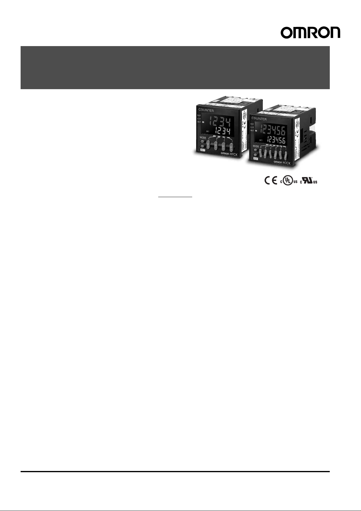
Multifunction Counter/Tachometer
H7CX Series
Please read and understand this catalog before purchasing the product s. Please cons ult your OMRON representative if you have any questions
or comments. Refer to Warranty and Application Considerations (page 64), and Safety Precautions (page 59).
DIN 48 × 48 mm Multifunction Counter/Tachometer Series
• Highly visible display with backlit negative transmissive LCD.
• Intuitive setting enabled using ergonomic up/down digit keys (4-digit models) and DIP switch.
• PNP/NPN switchable DC voltage input.
• Finger-safe terminals (screw terminal block models).
• Complies with IP66/NEMA4/UL Type 4X (when using the Y92S-29 Waterproof Packing and Y92F-30 Flush Mounting Adapter).
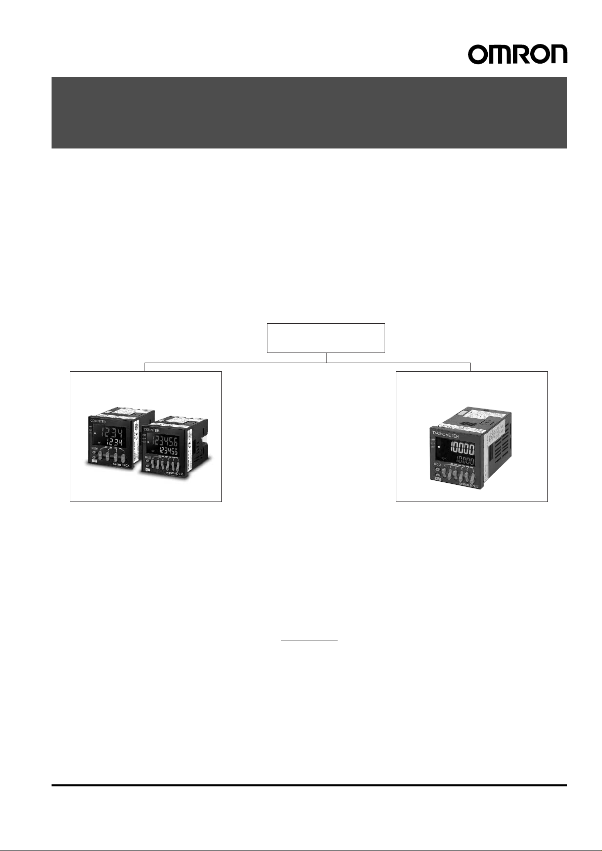
H7CX Series
H7CX-A H7CX-R
Multifunction Counter
Preset Counter
Total Counter
Batch Counter
Dual Counter
Tachometer
Tachometer
Contents
Multifunction Counter
H7CX-A…………………………………………………… 2
Tachometer
H7CX-R…………………………………………………… 42
Common to All Models
Safety Precautions……………………………………. 59
Warranty and Application Consideration………. 64
Multifunction Counter/Tachometer H7CX Series 1
Multifunction Preset Counter
H7CX-A
DIN 48 × 48 mm Multifunction Preset Counter
with a Bright, Easy-to-view, Negative
Transmissi ve LCD
• Programmable PV color to visually alert when output status
changes (screw terminal block models).
• Configurable as 1-stage c ounter, 2-stage counter , total and pre set counter , batch counter , dual counter , or tachometer . (Config urability varies w ith mo del .)
• Meets a variety of mounting requirements:
Screw terminal block models, and pin-style terminal models.
• Six-language instruction manual .
Contents
Model Number Structure ……………………………………………………..3
Ordering Information………… ……………………………….. ………………3
Specifications…………………………………………………………………….4
Connections ………………………………………………………………………8
Nomenclature…………………………………………………………………….12
Dimensions………………………………………………………………………..13
Operating Procedures …………………………………………………………17
Setting Procedure Guide…… . ………………………………. …………17
Operating Procedures (Counter Function)………………………..18
Operating Procedures (Tachometer Function)…………………..30
Operation in Configura tio n Se le c tion Mode ………………………36
Additional Information………………………………………………….. .. .. ….37
2 Multifunction Preset Counter H7CX-A
Model Number Structure
■Mo del Number Legend
H7CX-A@@@@@@
1 2 3 4 5 6
1. External connection
None:Screw terminals
11: 11-pi n socket
2. No. of digits
None:6 digits
4: 4 digits
3. Stage setting
None:1-stage setting
U: Factory-set to 1-stage setting
W: Factory-set to 2-stage setting
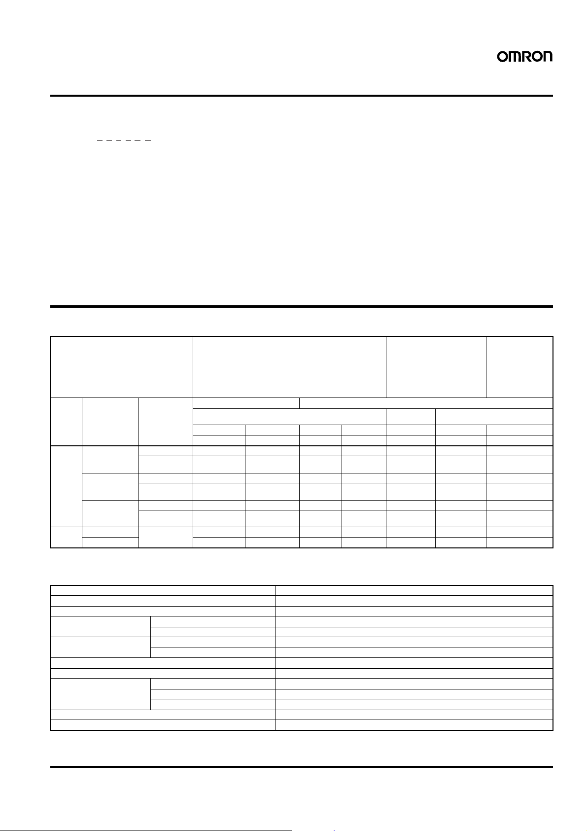
Ordering Information
■List of Models
4. Output type
None:Contact output or contact and transistor in combination
S: Transistor output
5. Supply voltage/external power supply
None:100 to 240 VAC at 50/60 Hz with 12 VDC power supply
D: 12 to 24 VDC without external power supply
D1: 12 to 24 VDC or 24 VAC at 50/60 Hz with 12 VDC power
supply
6. Case color
None:Black
G: Light gray (Munsell 5Y7/1): Produced upon request.
Supported configurations • 1-stage counter
Sensor
power
supply
12 VDC Contact output 100 to 240 VAC H7CX-A11 H7CX-A114 H7CX-A H7CX-A4 — H7CX-AW H7CX-A4W
None Contact output 12 to 24 VDC — — H7CX-AD H7CX-A4D — — —
Output type Supply voltage 11-pin socket Screw terminal
12 to 24 VDC/
24 VAC
Contact and
transistor output
Transistor output 100 to 240 VAC H7CX-A11S H7CX-A114S H7CX-AS H7CX-A4S — H7CX-AWS —
Transistor output — — H7CX-ASD H7CX-A4SD — H7CX-AWSD H7CX-A4WSD
100 to 240 VAC — — — — H7CX-AU — —12 to 24 VDC/
24 VAC
12 to 24 VDC/
24 VAC
• 1-stage counter with total counter
1-stage 1-stage
6 digits 4 digits 6 digits 4 digits 6 digits 6 digits 4 digits
H7CX-A11@ H7CX-A114@ H7CX-A@ H7CX-A4@ H7CX-AU@ H7CX-AW@ H7CX-A4W@
H7CX-A11D1 H7CX-A114D1 — — — H7CX-AWD1 —
— — — — H7CX-AUD1 — —
H7CX-A11SD1 — — — H7CX-AUSD1 H7CX-AWSD1 —
• 1-stage counter
• 2-stage counter
• 1-stage counter with total
counter
• 1-stage counter with batch
counter
• Dual counter (addition/subtraction)
• Tachometer
(See note.)
• 1-stage counter
• 2-stage counter
• 1-stage counter
with total counter
• 1-stage counter
with batch counter
• Dual counter (addition only)
2-stage
Note: Can be used as a 2-stage counter. In this case, each output can be flexibly allocated to either stage 1 or 2.
■Accessories (Order Separately)
Name Models
Flush Mounting Adapter (See note 1.) Y92F-30
Waterproof Packing (See note 1.) Y92S-29
Track Mounting/Front Connecting
Socket
Back Connecting Socket 11-pin P3GA-11
Hard Cover Y92A-48
Soft Cover Y92A-48F1
Mounting Track 50 cm (l) × 7.3 mm (t) P FP-50N
End Plate PFP-M
Spacer PFP-S
Note: 1. Supplied with screw-terminal models (i.e., excluding H7CX-A11@/-A114@ models).
2. Y92A-48G is a finger-safe terminal cover attached to the P3GA-11 Socket.
11-pin P2CF-11
11-pin, finger-safe type P2CF-11-E
11-pin, finger-safe type P3GA-11 with Y92A-48G (See note 2.)
1 m (l) × 7.3 mm (t) PFP-100N
1 m (l) × 16 mm (t) PFP-100N2
Multifunction Preset Counter H7CX-A 3
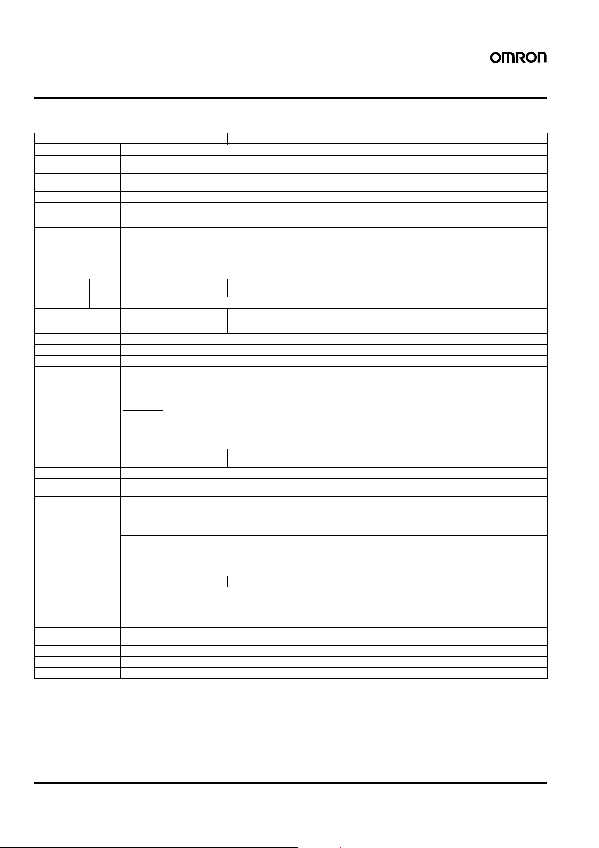
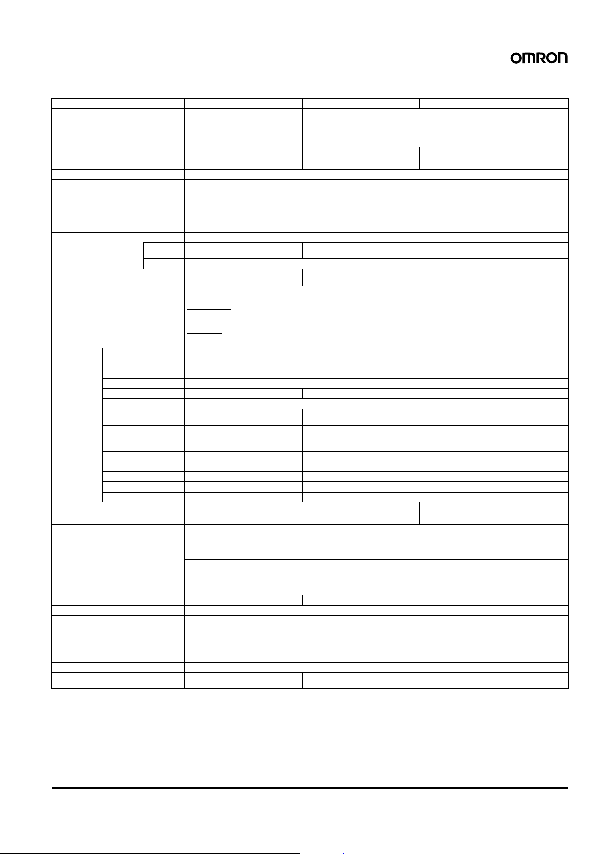
Specifications
■Ratings
Item H7CX-A4@ H7CX-A@ H7CX-A114@ H7CX-A11@
Classification Preset counter
Supported
configurations
Rated supply voltage
(See note 1.)
Operating voltage range 85% to 110% of rated supply voltage (90% to 110% at 12 VDC)
Power consumption Approx. 9.2 VA at 264 VAC
Mounting method Flush mounting Flush mounting, surface mounting, or DIN track mounting
External connections Screw terminals 11-pin socket
Terminal screw
tightening torque
Display
(See note 2.)
Digits 4 digits (
Max. counting speed 30 Hz or 5 kHz (selectable, ON/OFF ratio 1:1), common setting for CP1 and CP2
Input modes Increment, decrement, command, individual, and quadrature
Input signals CP1, CP2, reset, and total reset
Input method No-voltage input/voltage input (switchable)
Reset input Minimum reset input signal width: 1 or 20 ms (selectable), common setting for all inputs
Reset system External, manual, and automatic reset (internal according to C, R, P, and Q mode operation)
Output modes N, F, C, R, K-1, P, Q, A N, F, C, R, K-1, P, Q, A,
One-shot output time 0.01 to 99.99 s
Output type Contact type: SPDT
Control output Contact output: 3 A at 250 VAC/30 VDC, resistive load (cos
External power supply 12 VDC (
Key protection Ye s
Prescaling function Yes (0.001 to 9.999) Yes (0.001 to 99.999) Yes (0.001 to 9.999) Yes (0.001 to 99.999)
Decimal point
adjustment
Sensor waiting time 250 ms max. (Control output is turned OFF and no input is accepted during sensor waiting time.)
Memory backup EEPROM (overwrites: 100,000 times min.) that can store data for 10 years min.
Ambient temperature Operating:
Ambient humidity 25% to 85%
Case color Black (N1.5), light gray (Munsell 5Y7/1, produced upon request)
Attachments Waterproof packing, flush mounting adapter None
PV 11.5-mm-high characters, red or
SV 6-mm-high characters, green
Note: 1. Permissible ripple: 20% (p-p) max.
2. The display is lit only when the power is ON.
3. Only when the following modes are selected.
Input mode: command, individual, or quadrature; output mode: K-2, D, or L
1-stage co unter, 1-stage counter with total counter (s electable)
100 to 240 VAC (50/60 Hz), 12 to 24 VDC 100 to 240 VAC (50/60 Hz)
Approx. 7.2 VA at 26.4 VAC
Approx. 3.7 W at 12 VDC
0.5 N·m max. —
7-segment, negative transmissive LCD
green (programmable)
−999 to 9,999)
SV range: 0 to 9,999
No-voltage input
ON impedance: 1 kΩ max. (Leakage current: 5 to 20 mA at 0 Ω)
ON residual voltage: 3 V max.
OFF impedance: 100 k
Voltage input
High (logic) level: 4.5 to 30 VDC
Low (logic) level: 0 to 2 VDC (Input resistance: approx. 4.7 k
Transistor type: 1 transistor
Minimum applied load: 10 mA at 5 VDC (failure level: P, reference value)
Transistor output: NPN open collector, 100 mA at 30 VDC
NEMA B300 Pilot Duty, 1/4 HP 3-A resistive load at 120 VAC, 1/3 HP 3-A resistive load at 240 VAC
±10%), 100 mA (except for H7CX-A@D models)
Refer to Safety Precautions (page 60) for details.
Yes (rightmost 3 digits)
Storage:
−10 to 55°C (−10 to 50°C if counters are mounted side by side) (with no icing or condensation)
−25 to 65°C (with no icing or condensation)
Ω min.
9-mm-high characters, re d or
green (programmable)
6 digits (−99,999 to 999,999)
SV range:
(See note 3.) or 0 to 999,999
K-2, D, L
Residual voltage: 1.5 VDC max. (approx. 1 V)
Leakage current: 0.1 mA max.
−99,999 to 999,999
24 VAC (50/60 Hz)/12 to 24 VDC
11.5-mm-high characters, red 9-mm-high characters, red
−999 to 9,999)
4 digits (
SV range: 0 to 9,999
Ω)
N, F, C, R, K-1, P, Q, A N, F, C, R, K-1, P, Q, A,
φ=1)
6 digits (−99,999 to 999,999)
SV range:
(See note 3.) or 0 to 999,999
K-2, D, L
−99,999 to 999,999
4 Multifunction Preset Counter H7CX-A
■Ratings (contd.)
Item H7CX-A4W@ H7CX-AW@ H7CX-AU@
Classification Preset counter Preset counter/tachometer
Supported configurati o ns 1-stage counter, 2-stage counter, 1-stage
Rated supply voltage (See note 1.) 100 to 240 VAC (50/60 Hz),
Operating voltage range 85% to 110% of rated supply voltage (90% to 110% at 12 VDC)
Power consumption Approx. 9.2 VA at 264 VAC
Mounting method Flush mounting
External connections Screw terminals
Terminal screw tightening torque 0.5 N·m max.
Display (See note 2.) 7-segment, negative transmissive LCD
PV 11.5-mm-high characters, red or green
Digits 4 digits (−999 to 9,999)
Input signals CP1, CP2, reset 1, and reset 2
Input method No-voltage input/voltage input (switchable)
Counter Max. counting speed 30 Hz or 5 kHz (selectable, ON/OFF ratio 1:1), common setting for CP1 and CP2
Input mode Increment, decrement, command, individual, and quadrature
Reset input Minimum reset input signal width: 1 or 20 ms (selectable), common setting for all inputs
Reset system External, manual, and automatic reset (internal according to C, R, P, and Q mode operation)
Output modes N, F, C, R, K-1, P, Q, A N, F, C, R, K-1, P, Q, A, K-2, D, L, H
One-shot output time 0.01 to 99.99 s
Tachometer Pulse measurement
Output type H7CX-A4W/-AW/-AWD1: SPDT (OUT2) and SPST-NO (OUT1)
Control output Contact output: 3 A at 250 VAC/30 VDC, resistive load (cosφ=1)
External power supply 12 VDC (±10%), 100 mA (except for H7CX-A@D models)
Key protection Yes
Prescaling function Yes (0.001 to 9.999) Yes (0.001 to 99.999)
Decimal point adjustment Yes (rightmost 3 digits)
Sensor waiting time 250 ms max. (Control output is turned OFF and no input is accepted during sensor waiting time.)
Memory backup EEPROM (overwrites: 100,000 times min.) that can store data for 10 years min.
Ambient temperature Operating: −10 to 55°C (−10 to 50°C if counters are mounted side by side) (with no icing or condensation)
Ambient humidi ty 25% to 85%
Case color Black (N1.5), light gray (Munsell 5Y7/1, produced upon request)
Attachments Waterproof packing, flush moun ting adapt-erWaterproof packing, flush mounting adapter, labels for counter/tachometer DIP switch settings
method
Max. counting speed — 30 Hz or 10 kHz (selectable)
Measuring ranges — 30 Hz: 0.01 to 30.00 Hz
Measuring accuracy — ±0.1% FS ±1 digit max. (at 23 ±5°C)
Output modes — HI-LO, AREA, HI-HI, LO-LO
Auto-zero time — 0.1 to 99.9 s
Startup time — 0.0 to 99.9 s
Average processing — OFF/2/4/8 times
SV 6-mm-high characters, green
counter with total counter , 1-stage count er
with batch counter, dual counter (addition
only) (selectable)
12 to 24 VDC
Approx. 7.2 VA at 26.4 VAC
Approx. 3.7 W at 12 VDC
(programmable)
SV range: 0 to 9,999
No-voltage input
ON impedance: 1 kΩ max. (Leakage current: 5 to 20 mA at 0 Ω)
ON residual voltage: 3 V max.
OFF impedance: 100 kΩ min.
Voltage input
High (logic) level: 4.5 to 30 VDC
Low (logic) level: 0 to 2 VDC (Input resistance: approx. 4.7 kΩ)
— Periodic measurement (Sampling period: 200 ms)
H7CX-A4WSD/-AWS/-AWSD/-AWSD1: 2 transistors
Minimum applied load: 10 mA at 5 VDC (failure level: P, reference value)
Transistor output: NPN open collector, 100 mA at 30 VDC
NEMA B300 Pilot Duty, 1/4 HP 3-A resistive load at 120 VAC, 1/3 HP 3-A resistive load at 240 VAC
Refer to Safety Precautions (page 60) for details.
Storage: −25 to 65°C (with no icing or condensation)
Residual voltage: 1.5 VDC max. (approx. 1 V)
Leakage current: 0.1 mA max.
1-stage counter, 2-stage counter, 1-stage counter with total counter, 1-stage counter with batch
counter, dual counter (addition/subtraction), tachometer (selectable)
100 to 240 VAC (50/60 Hz),
24 VAC (50/60 Hz)/12 to 24 VDC,
12 to 24 VDC
9-mm-high characters, red or green (programmable)
6 digits (−99,999 to 999,999 or 0 to 999,999 when using as Tachometer)
SV range: −99,999 to 999,999 (See note 3.) or 0 to 999,999
10 kHz: 0.01 Hz to 10 kHz
100 to 240 VAC (50/60 Hz),
24 VAC (50/60 Hz)/12 to 24 VDC
H7CX-AU/-AUD1: SPDT and 1 transistor
H7CX-AUSD1: 2 transistors
(Output allocation possible)
Note: 1. Permissible ripple: 20% (p-p) max.
2. The display is lit only when the power is ON.
3. Only when the following modes are selected.
— Input mode: command, individual, or quadrature; output mode: K-2, D, L, or H
— Dual count calculating mode: SUB; output mode: K-2, D, L, or H in dual counter operation
Multifunction Preset Counter H7CX-A 5
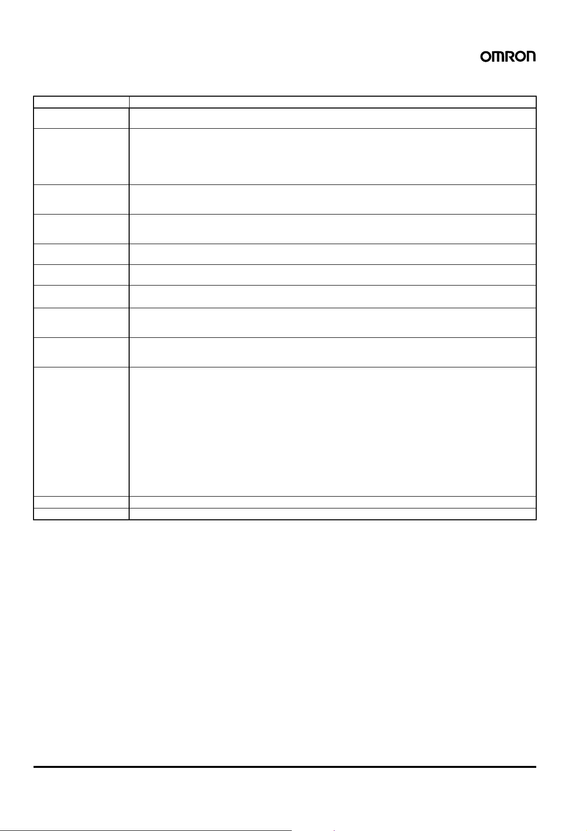
■Characteristics
item H7CX
Insulation resistance 100 M
Dielectric strength 2,000 VAC, 50/60Hz for 1 min between current-carrying metal parts and non-current-carrying metal parts
Impulse withstand
voltage
Noise immunity
Static immunity Destruction: 15 kV
Vibration resistance Destruction: 10 to 55 Hz with 0.75-mm single amplitude, four cycles each in three directions (8 minutes per cycle)
Shock resistance
Life expectancy Mechanical: 10,000,000 operations min.
Approved safety
standards
(See notes 1 and 2.)
EMC (EMI) EN61326
Degree of protection Panel surface: IP66, NEMA 4 (indoors), and UL Ty pe 4X (indoors) (See note 2.)
Weight Approx. 140 g
Note: 1. To meet UL listing requirements w ith the H7CX-A11@ models, an OMRON P2CF-11-@ or P3G A-11 Socket must be mounted on the
H7CX. Otherwise, H7CX-A11@ models are considered to meet UL508 recognition requirements.
2. The Y92S-29 Waterproof Packing and Y92F-30 Flush Mounting Adapter are necessary to ensure IP66, NEMA4, and UL Type 4X waterproofing between the H7CX and installation panel.
Ω min. (at 500 VDC) between current-carrying terminal and exposed non-current-carrying metal parts, and be-
tween non-continuous contacts
2,000 VAC (for 100 to 240 VAC), 50/60 Hz for 1 min between power supply and input circuit (1,000 VAC for 24 VAC/
12 to 24 VDC)
1,000 VAC (for H7CX-@SD/-@SD1), 50/60 Hz for 1 min between control output, power supply, and input circuit
(2,000 VAC for models other than H7CX-@SD/-@SD1)
1,000 VAC, 50/60 Hz for 1 min between non-continuous contacts
3 kV (between power terminals) for 100 to 240 VAC, 1 kV for 24 VAC/12 to 24 VDC and 12 to 24 VDC
4.5 kV (between current-carrying terminal and exposed non-current-carrying metal parts) for 100 to 240 VAC,
1.5 kV for 24 VAC/12 to 24 VDC and 12 to 24 VDC
±1.5 kV (between power terminals) for 100 to 240 VAC and 24 VAC/12 to 24 VDC, ±480 V for 12 to 24 VDC
±600 V (between input terminals)
Square-wave noise by noise simulator (pulse width: 100 ns/1
Malfunction: 8 kV
Malfunction: 10 to 55 Hz with 0.35-mm single amplitude, four cycles each in three directions (8 minutes per cycle)
Destruction: 294 m/s
Malfunction: 98 m/s
Electrical: 100,000 operations min. (3 A at 250 VAC, resistive load)
UL508/Listing, UL 50 Type 4X for indoor use (enclosure rating)
CSA C22.2 No. 14, conforms to EN61010-1 (Pollution degree 2/overvoltage category II)
Conforms to VDE0106/P100 (finger protection).
Emission Enclosure: EN55011 Group 1 class A
Emission AC mains: EN55011 Group 1 class A
(EMS) EN61326
Immunity ESD: EN61000-4-2: 4 kV contact discharge (level 2);
Immunity RF-interference: EN61000-4-3: 10 V/m (Amplitude-modulated, 80 MHz to 1 GHz) (level 3);
Immunity Conducted Disturbance: EN61000-4-6: 10 V (0.15 to 80 MHz) (level 3)
Immunity Burst: EN61000-4-4: 2 kV power-line (level 3);
Immunity Surge: EN61000-4-5: 1 kV line to lines (power and output lines) (level 2);
Immunity Voltage Dip/Interruption: EN61000-4-11: 0.5 cycle, 100% (rated voltage)
2
each in three directions
2
each in three directions
See Life-test Curve on page 7.
µs, 1-ns rise)
8 kV air discharge (level 3)
10 V/m (Pulse-modulated, 900 MHz
1 kV I/O signal-line (level 4)
2 kV line to ground (power and output lines) (level 3)
±5 MHz) (level 3)
6 Multifunction Preset Counter H7CX-A
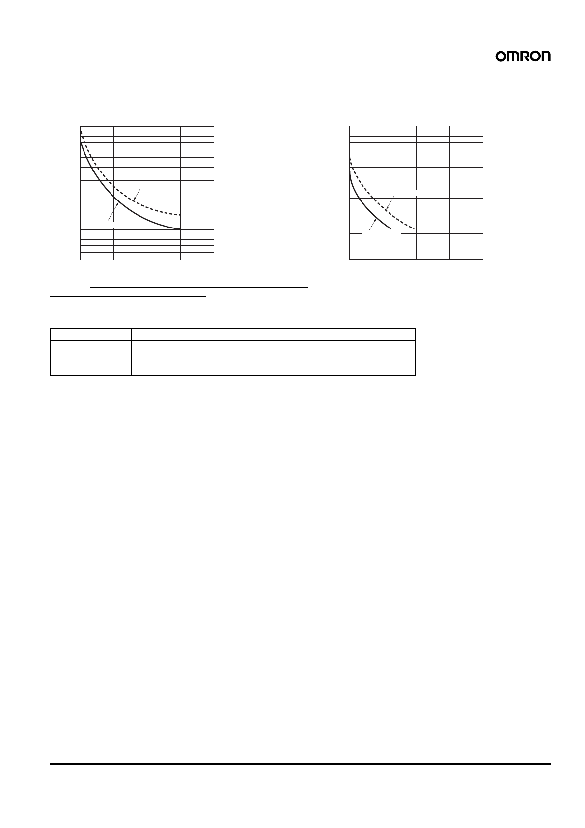
■Li fe-test Curve (Reference Values)
Resistive Load Inductive Load
1,000
)
3
700
500
1,000
)
700
3
500
300
No. of operations (×10
250 VAC (cosφ=1)
100
70
50
01 2 3
30 VDC (cosφ=1)
Load current (A)
4
300
30 VDC (L/R=7 ms)
No. of operations (×10
100
250 VAC cosφ=0.4
70
50
01 2 3
4
Load current (A)
Reference: A current of 0.15 A max. can be switched at 125 VDC (cosφ=1) and current of 0.1 A max. can be switched if L/R=7 ms. In both cases,
a life of 100,000 operations can be expected.
The minimum applicable load is 10 mA at 5 VDC (failure level: P).
■I nrush Current (R eference Values)
Model Voltage Applied voltage Inrush current (peak value) Time
H7CX-A11/-AW 100 to 240 VAC 264 VAC 5.8 A 0.7 ms
H7CX-A11D1/-AWD1 24 VAC/12 to 24 VDC 26.4 VAC 10.4 A 1.2 ms
H7CX-AD 12 to 24 VDC 26.4 VDC 6.0 A 1.2 ms
Multifunction Preset Counter H7CX-A 7
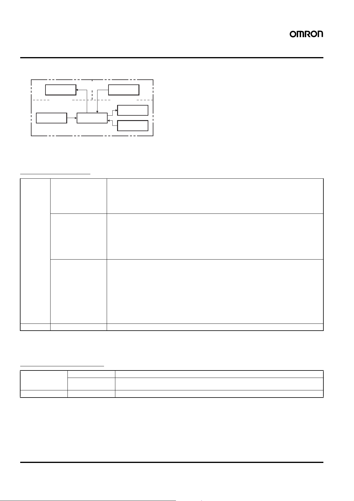
Connections
■Block Diagram
(Basic
Output circuit
(Basic
insulation)
Input circuit
Note: All models except for H7CX-@D (models with 12 to 24-VDC power supplies) have basic insulation.
■I/O Fu nctions
Using as a Counter
insulation) Power supply
Internal control
circuit
circuit
(See note.)
Display circuit
Key switch
circuit
Inputs CP1, CP2 • In general (except for dual counter mode)
Reset or Reset 1 • In general (except for dual counter mode)
Total Reset or
Reset 2
(See note 2.)
Outputs OUT1, OUT2 Outputs take place according to designated output mode when corresponding preset is reached.
Note: 1. In increment mode or increment/decrement mode, the present value returns to 0; in decrement mode, the present value returns to the
set value with 1-stage models, and returns to set value 2 with 2-stage models.
2. The reset indicator will not be lit when the total reset or reset 2 input is ON.
Reads counting signals
Increment, decrement, command, individual, and quadrature inputs accepted.
• When used as a dual counter
Reads CP1 count signals with CP1 input and CP2 count signals with CP2 input.
Increment signals can be input.
Resets present value and outputs (OUT2 when using the batch counter). (See note 1.)
Counting cannot be performed during reset/reset 1 input.
The reset indicator is lit during reset input.
• When used as a dual counter
Resets the CP1 present value (to 0).
Counting for CP1 input cannot be performed during reset 1 input.
The reset indicator is lit during reset 1 input.
• When used as a 1-stage/2-stage counter
Does not operate (Not used).
• When used as a total and preset counter
Resets the total count value.
Holds the total count value at 0 during total reset input.
• When used as a batch counter
Resets the batch count value and batch output (OUT1).
Holds the batch count value at 0 during reset 2 input.
• When used as a dual counter
Resets the CP2 present value.
Counting for CP2 input cannot be performed during reset 2 input.
Using as a Tachometer
Inputs CP1, CP2 Reads counting signals. (CP2 input is not available.)
Reset 1, Reset 2 Holds the measurement value and outputs. (Reset 2 input is not available.)
Outputs OUT1, OUT2 Outputs signals according to the specified output mode when a set value is reached.
8 Multifunction Preset Counter H7CX-A
The reset indicator is lit during hold.
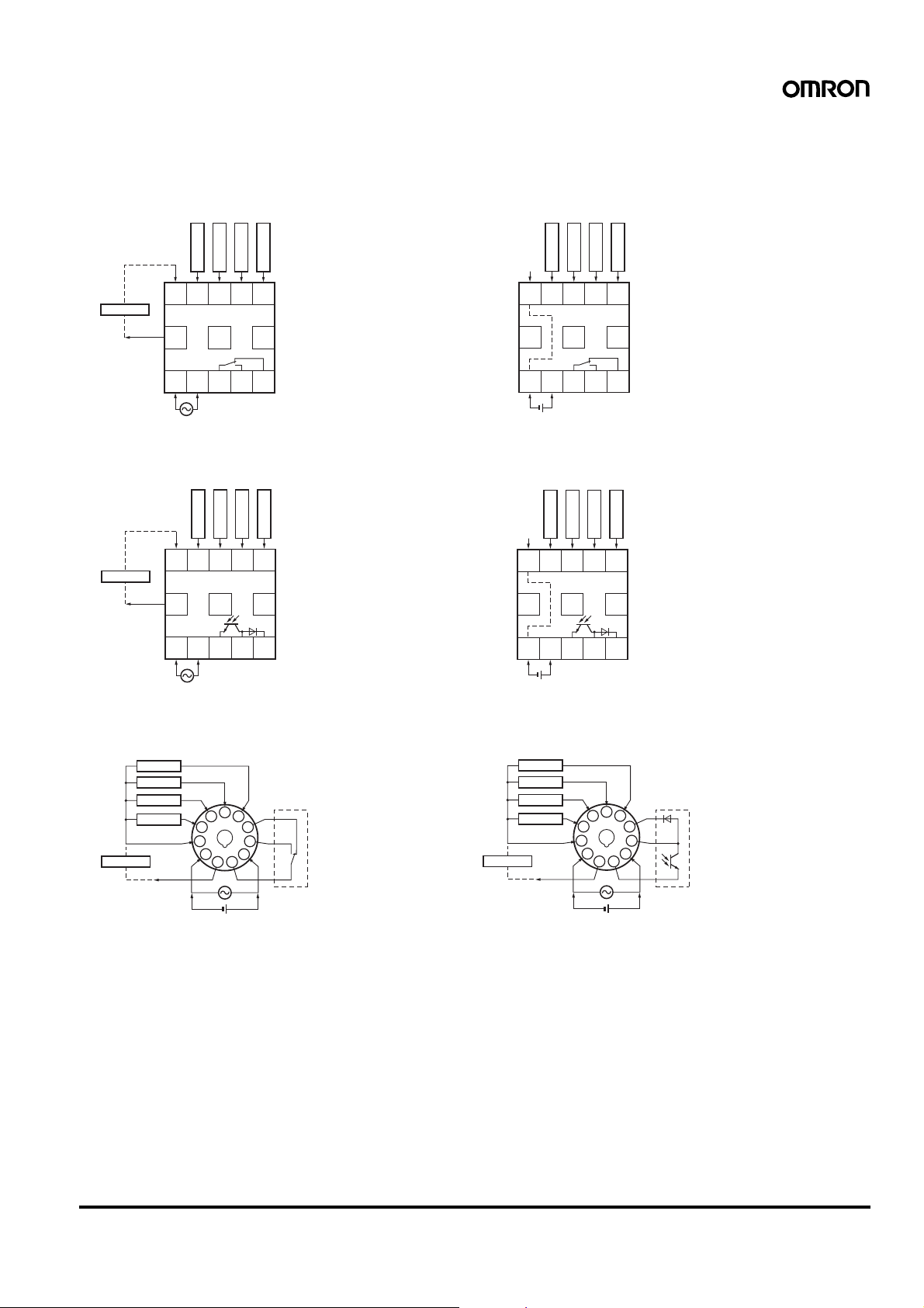
■Te rminal Arrangement
Confirm that the power supply meets specifications before use.
H7CX-A/-A4
1-stage Contact Output
CP2
Reset
0 V
(−)
Sensor, etc.
(+)
External power
supply
678910
12 VDC
11 12 13
1234
Unused Unused
OUT
H7CX-AS/-A4S
1-stage Transistor Output
CP2
Reset
0 V
(−)
Sensor, etc.
(+)
External power
supply
678910
12 VDC
11 12 13
Unused Unused
CP1
CP1
Total reset
5
Total reset
H7CX-AD/-A4D
1-stage Contact Output
0 V
678910
Unused Unused Unused
11 12 13
1234
(+)(−)
Terminals 1 and 6 are connected internally.
Note:
Total reset
5
OUT
CP2
CP1
Reset
H7CX-ASD/-A4SD
1-stage Transistor Output
CP2
CP1
Reset
0 V
678910
Unused Unused Unused
11 12 13
Total reset
12345
OUT
H7CX-A11/-A114/-A11D1/-A114D1
1-stage Contact Output
Reset
CP1
CP2
0 V
5
4
3
2
1
(−)
Total reset
(−)
Sensor, etc.
12 VDC
(+)
External power supply
Note: Do not connect unused terminals as relay terminals.
6
11
7
10
(+)
Internal circuit
8
9
OUT
12345
(−)
Terminals 1 and 6 are connected internally.
Note:
OUT
(+)
H7CX-A11S/-A114S/-A11SD1
1-stage Transistor Output
Reset
CP1
CP2
Total reset
(−)
Sensor, etc.
12 VDC
(+)
External power supply
0 V
5
4
3
2
1
(−)
6
11
(+)
7
8
9
10
Internal circuit
OUT
Multifunction Preset Counter H7CX-A 9
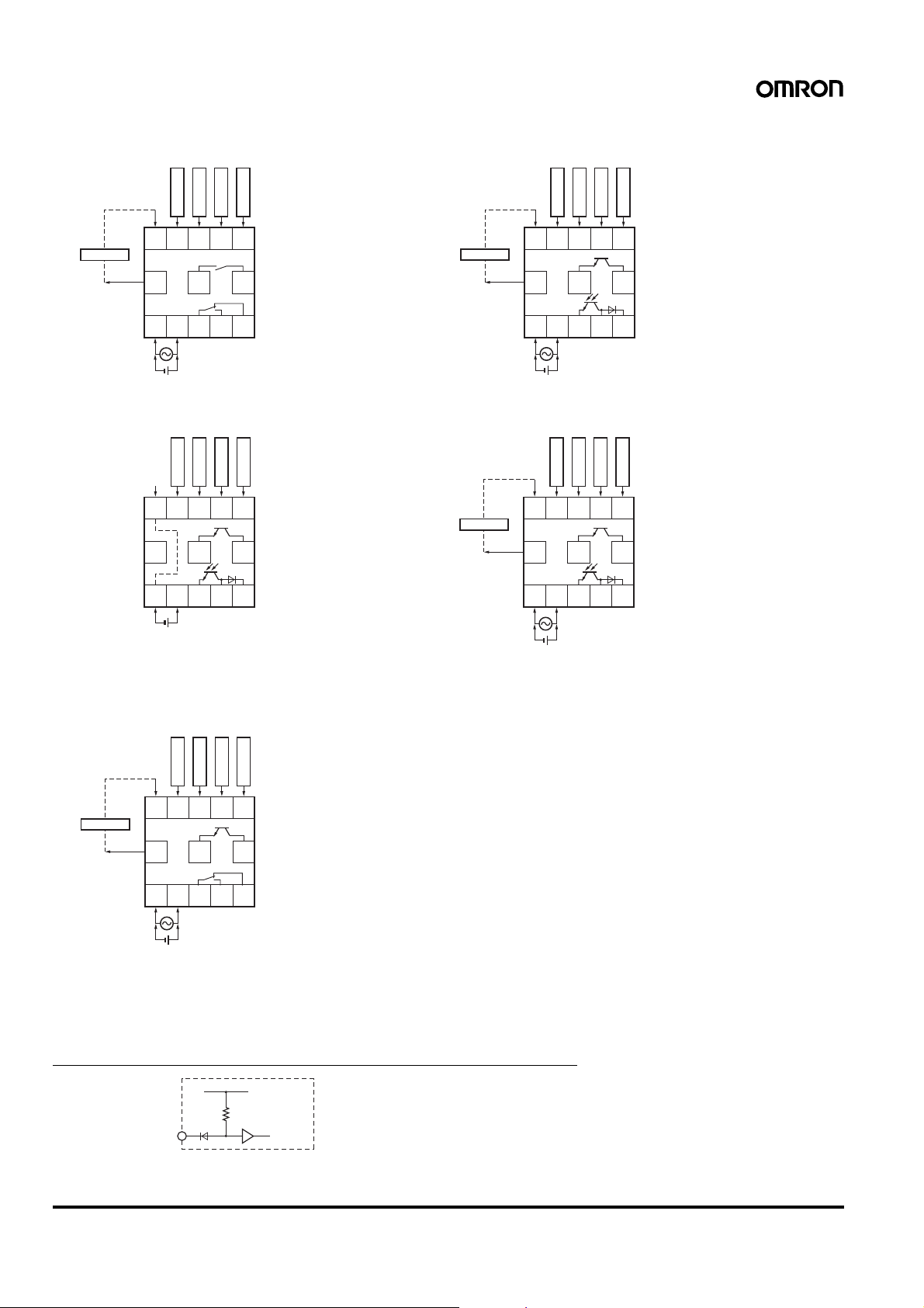
H7CX-AW/-A4W/-AWD1
2-stage Contact Output
Reset 1
0 V
(−)
Sensor, etc.
(+)
External power
supply
678910
12 VDC
11 12 13
CP2
CP1
Reset 2
OUT1
H7CX-AWS/-AWSD1
2-stage Transistor Output
CP2
Reset 1
0 V
(−)
Sensor, etc.
(+)
External power
supply
678910
12 VDC
11 12 13
CP1
Reset 2
OUT1
12345
OUT2
(−)
(+)
H7CX-AWSD/-A4WSD
2-stage Transistor Output
CP2
CP1
Note: 1.
2.
Reset 1
0 V
678910
Unused
11 12 13
12345
(+)
(−)
Terminals 1 and 6 are connected internally.
Do not connect unused terminals as relay terminals.
Reset 2
OUT1
OUT2
H7CX-AU/-AUD1
1-stage Contact, 1-stage Transistor Output
CP2
CP1
(−)
Sensor, etc.
(+)
12 VDC
External power
supply
Reset 1
0 V
678910
11 12 13
Reset 2
OUT1 or 2
12345
OUT2
(+)(−)
H7CX-AUSD1
1 or 2-stage Transistor Output
CP2
CP1
Reset 1
0 V
(−)
Sensor, etc.
(+)
External power
supply
Each output can be flexibly allocated to
Note:
either stage 1 or 2 in function selection
mode.
678910
12 VDC
11 12 13
12345
OUT 1 or 2
(+)(−)
Reset 2
OUT1 or 2
12345
OUT 1 or 2
(+)(−)
Note: Each output can be flexibly allocated to either
stage 1 or 2 by setting in function selection mode.
■I nput Circuits
CP1, CP2, Reset/Reset 1, and Total Reset/Reset 2 Input
+14 V
1 kΩ
IN
Note: The circuit shown above is for no-voltage input (NPN input).
10 Multifunction Preset Counter H7CX-A
Internal
circuit
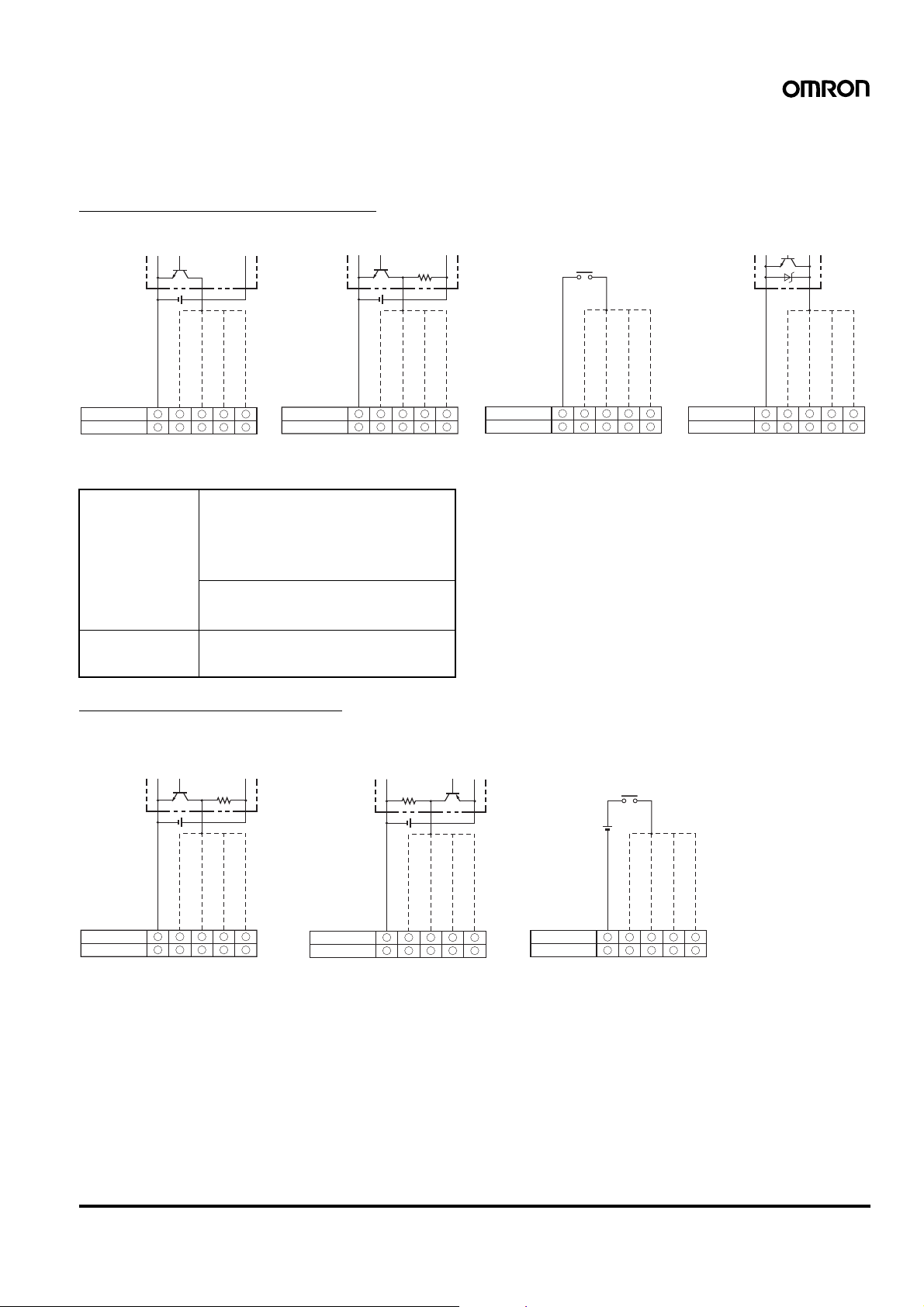
■Input Connections
The inputs of the H7CX are no-voltage (short-circuit or open) inputs or voltage inputs.
When using as a tachometer, CP2 input and total reset/reset 2 input are not available.
No-voltage Inputs (NPN Inputs)
Open Collector
PLC or
sensor
0 V
Input
Reset/reset 1 input
CP2 input
H7CX-A
H7CX-A11
Operates when the transistor turns ON.
6 7 8 9
@
3 7 5 6 4
@
Voltage Output
Sensor
CP1 input
Total reset/reset 2 input
10
H7CX-A
@
H7CX-A11
@
Operates when the transistor turns ON.
0 V
Input
Reset/reset 1 input
CP2 input
6 7 8 9
3 7 5 6104
Contact Input
CP1 input
Total reset/reset 2 input
H7CX-A
@
H7CX-A11
@
Operates when the contact turns ON.
0 V
Input
Reset/reset 1 input
CP2 input
6 7 8 9
3 7 5 6104
DC Two-wire Sensor
CP1 input
Total reset/reset 2 input
H7CX-A
@
H7CX-A11
@
Operates when the transistor turns ON.
Input
Reset/reset 1 input
CP2 input
6 7 8 9
3 7 5 6104
CP1 input
No-voltage Input Signal Levels Applicable Two-wire Sensor
No-contact input Short-circuit level
Transistor ON
Residual voltage: 3 V max.
Impedance when ON: 1 k
Ω max.
(The leakage current is 5 to 20 mA when the
impedance is 0
Ω.)
Open level
Transistor OFF
Impedance when OFF: 100 k
Ω min.
Contact input Use contact which can adequately switch
5 mA at 10 V.
Maximum applicable voltage: 30 VDC max.
Leakage current: 1.5 mA max.
Switching capacity: 5 mA min.
Residual voltage: 3 VDC max.
Operating voltage: 10 VDC
Total reset/reset 2 input
Voltage Inputs (PNP Inputs)
No-contact Input
(NPN Transistor)
Sensor
0 V
Input
Reset/reset 1 input
CP2 input
CP1 input
H7CX-A@
H7CX-A11@
Operates when the transistor turns OFF.
6 7 8 9
3 7 5 6104
Voltage Input Signal Levels
High level (Input ON): 4.5 to 30 VDC
Low level (Input OFF): 0 to 2 VDC
Maximum applicable voltage: 30 VDC max.
Input resistance: Approx. 4.7 k
Total reset/reset 2 input
No-contact Input
(PNP Transistor)
H7CX-A@
H7CX-A11@
Operates when the transistor turns ON.
Ω
Sensor
0 V
Input
Reset/reset 1 input
CP2 input
6 7 8 9
3 7 5 6104
Contact Input
CP1 input
Total reset/reset 2 input
H7CX-A@
H7CX-A11@
Operates when the contact turns ON.
0 V
Input
Reset/reset 1 input
6 7 8 9
3 7 5 6104
CP2 input
CP1 input
Total reset/reset 2 input
Multifunction Preset Counter H7CX-A 11
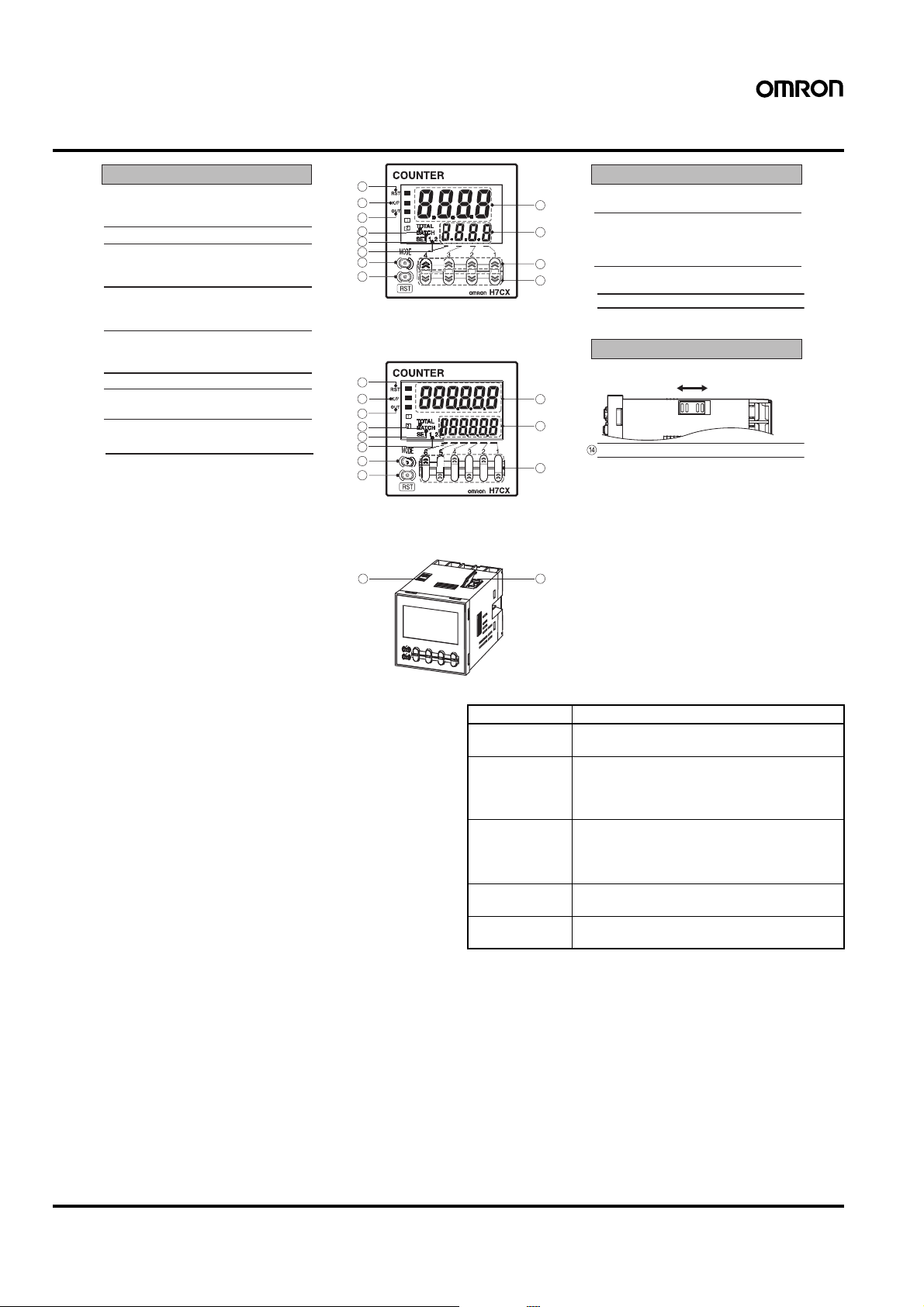
Nomenclature
Indicators Operation Keys
A
Reset Indicator (Orange)
Lit when the reset input (1) or reset key
is ON.
B
Key Protection Indicator (Orange)
C
Control Output Indicator (Orange)
OUT: One stage
OUT1, OUT2: Two stages
D
Total Count Indicator
Lit when the total count value is
displayed.
E
Batch Indicator
Lit when the batch count value is
displayed.
F
Set Value 1, 2 Stage Indicator
G
Present Value (Main Display)
Character height: 11.5 mm (6-digit: 9mm)
H
Set Value (Sub-display)
Character height: 6 mm
1
2
3
4
5
6
9
10
Front view of 4-di
1
2
3
4
5
6
9
10
it mode
Front view of 6-digit mode
13 14
I
7
8
Mode Key
Used to switch mode and setting items.
J
Reset Key
The operation of the reset function
depends on the configuration selected
11
12
as shown in the table below.
K
Up Keys: 1 to 4
(6-digit models: 1 to 6)
L
Down Keys: 1 to 4
Switches
M
Key Protect Switch
7
8
11
(Factory setting) OFF ON
DIP Switch
Reset Operation by Reset Key
Configuration Reset operation
1-stage/2-stage
Resets the present value and outputs.
counter
Total and preset
counter
• Resets the present value and outputs.
• When the total count value is displayed, resets
the present value, the total count value, and
outputs.
Batch counter • Resets the present value and OUT2.
• When the batch count value is displayed,
resets the present value, the batch count
value, and outputs.
Dual counter Resets the CP1 present value, CP2 present val-
ue, dual count value, and outputs.
Tachometer Maintains the measured value and outputs (hold
function).
12 Multifunction Preset Counter H7CX-A
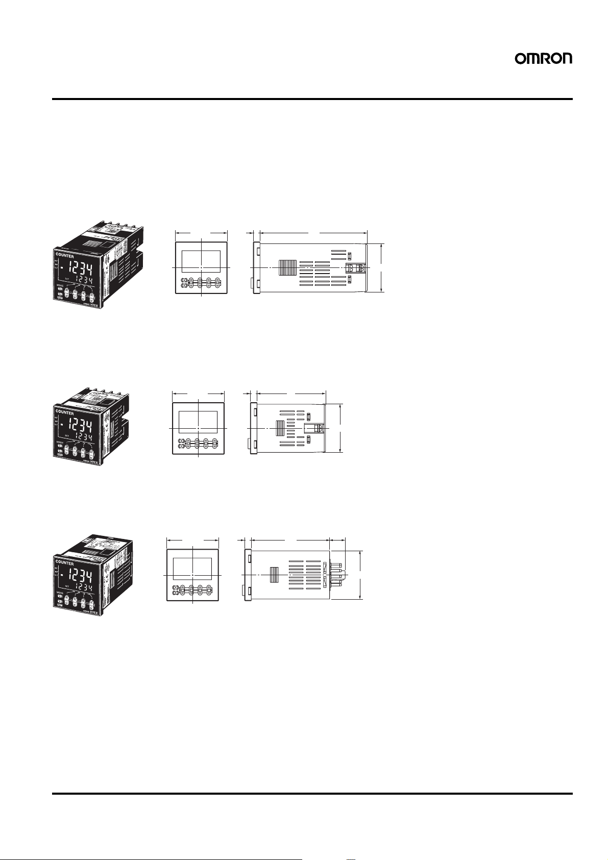
Dimensions
Note: All units are in millimeters unless otherwise indicated.
■Co unter (without Flush Mountin g Adapter)
Screw-terminal Models with External Power Supplies (Flush Mounting)
• H7CX-A
• H7CX-AS
• H7CX-A4
• H7CX-A4S
• H7CX-AW
• H7CX-AWS
• H7CX-A4W
• H7CX-AWD1
• H7CX-AWSD1
• H7CX-AU
• H7CX-AUD1
• H7CX-AUSD1
48×48
6
100
44.8×44.8
Note: M3.5 terminal screw (effective length: 6 mm)
Screw-terminal Models without External Power Supplies (Flush Mounting)
• H7CX-AD
• H7CX-ASD
• H7CX-A4D
• H7CX-A4SD
• H7CX-AWSD
• H7CX-AWSD
48×48
6
64
44.8×44.8
Note: M3.5 terminal screw (effective length: 6 mm)
11-pin Socket Models (Flush Mounting/Surface Mounting)
• H7CX-A11
• H7CX-A11S
• H7CX-A11D1
• H7CX-A11SD1
• H7CX-A114
• H7CX-A114S
• H7CX-A114D1
48×48
6
72.5
14.4
44.8×44.8
Multifunction Preset Counter H7CX-A 13
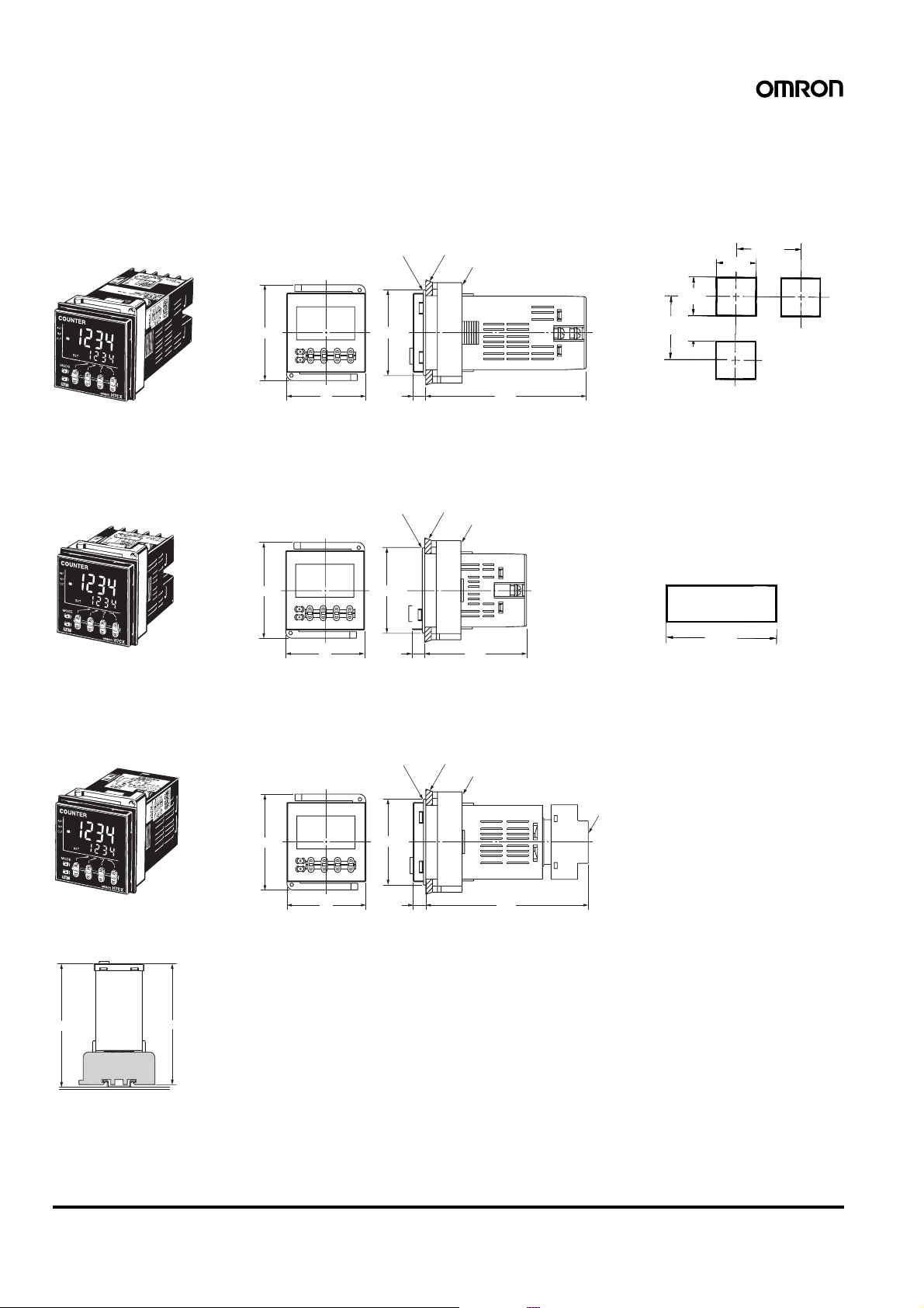
■Dimensions with Flush Mounting Adapter
Screw-terminal Models with External Power Supplies
(Provided with Adapter and Waterproof Packing)
• H7CX-A
• H7CX-AS
• H7CX-A4
• H7CX-A4S
• H7CX-AW
• H7CX-AWS
• H7CX-A4W
• H7CX-AWD1
• H7CX-AWSD1
• H7CX-AU
• H7CX-AUD1
• H7CX-AUSD1
58
Y92S-29 (provided)
Waterproof Packing
(51)
Panel
Y92F-30 (provided)
Flush Mounting Adapter
Panel Cutouts
Panel cutouts are as
shown below.
(according to DIN43700).
+0.6
45
−0
+0.6
45
−0
60 min.
15 min.
60 min.
48 98.57.5
Screw-terminal Models without External Power Supplies
(Provided with Adapter and Waterproof Packing)
• H7CX-AD
• H7CX-ASD
• H7CX-A4D
• H7CX-A4SD
• H7CX-AWSD
• H7CX-A4WSD
Y92S-29 (provided)
Waterproof Packing
58
48
(51)
7.5
Panel
Y92F-30 (provided)
Flush Mounting Adapter
62.5
11-pin Socket Models
(Adapter and Waterproof Packing Ordered Separately)
• H7CX-A11
• H7CX-A11S
• H7CX-A11D1
• H7CX-A11SD1
• H7CX-A114
• H7CX-A114S
• H7CX-A114D1
Y92S-29 (order separately)
Waterproof Packing
58
(51)
Y92F-30 (order separately)
Panel
Flush Mounting Adapter
Note: 1. The mounting panel thickness
should be 1 to 5 mm.
2. To allow easier operability, it is
recommended that Adapters are
mounted so that the gap between
sides with hooks is at least 15 mm
(i.e., so that the panel cutout interval
is at least 60 mm).
3. It is possible to mount counters
side by side, but only in the
direction without the hooks.
If they are mounted side-by-side,
water-resistant specifications
cannot be ensured.
n side by side mounting
A
A = (48n − 2.5)+1
0
With Y92A-48F1 attached.
A = {48n−2.5 + (n−1) x 4}
P3GA-11
(order separately)
Back Connecting
Socket
With Y92A-48 attached.
A = (51n−5.5)
+1
0
+1
0
48
7.5
98.7
■Dimensions with Front Connecting Socket
H7
—
P2CF-1
Note: These dimensions vary with the kind of DIN track (reference value).
14 Multifunction Preset Counter H7CX-A
109.7
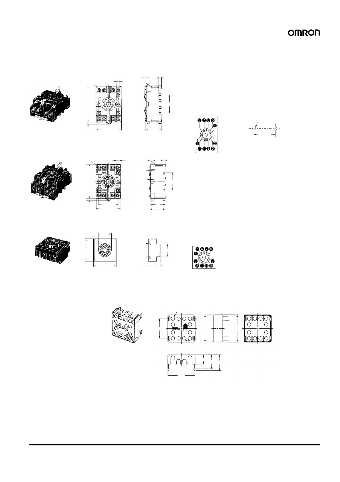
■Accessories (Order Separately)
Note: All units are in millimeters unless otherwise indicated.
Track Mounting/Front Connecting Socket
P2CF-11
Eleven,
M3.5 x 7.5 sems
7.8
3
4.5
70 max.
4
50 max.
P2CF-11-E (Finger-safe Terminal T ype)
Conforming to VDE0106/P100
Eleven,
M3.5 x 7.5 sems
70 max.
4
40±0.2
50 max.
Back Connecting Socket
P3GA-11
27 dia.
45
45
Two, 4.5-dia.
holes
7.8
Two, 4.5-dia.
holes
4.5
5
3
1.2
31.2 max.
30
31.2 max.
16.3
35.4
25.6
6.2
Terminal Arrangement/
Internal Connections
(Top Vie w)
4.5
35.4
Terminal Arrangement/
Internal Connections
(Bottom View)
Surface Mounting Holes
Two, 4.5 dia. or two, M4
40±0.2
Note: Track mounting is also possible.
Finger protection can be ensured by using in combination with the Y92A-48G Terminal Cover.
Note:
Finger-safe T erminal Cover
Conforming to VDE0106/P100
Y92A-48G
(Attachment for P3GA-11
Twelve, 6.4-dia. holes
Socket)
34
47.4
47.7 x 47.7
16.5
24.6
48 x 48
27.6
Multifunction Preset Counter H7CX-A 15
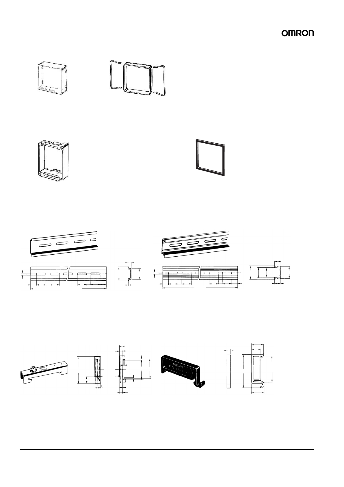
Hard Cover
Y92A-48
Soft Cover
Y92A-48F1
Note: 1. Depending on the operating environment, the condition of
resin products may deteriorate, and may shrink or become
harder. Therefore, it is recommended that resin products
are replaced regularly.
2. The H7CX’s panel surface is water-resistive (conforming to
IP66) and so even if drops of water penetrate the gaps between the keys, there will be no adverse effect on internal
circuits. If, howe ver, there is a possibility of oil being present
on the operator’s hands, use the Soft Cover. The Soft Cover
ensures protection equivalent to IP54F against oil. Do not,
however, use the H7CX in locations where it would come in
direct contact with oil.
Flush Mounting Adapter
(provided with screw-terminal models)
Waterproof Packing
(provided with screw-terminal models)
Y92F-30 Y92S-29
When using the Y92S-29, the degree of protection for the H7CX’s
panel surface conforms to NEMA4, UL Type 4X, and IP66. (Depending on the operating environment, the condition of the panel may
deteriorate, shrink, or become harder. Therefore, regular replacement is recommended.)
Mounting T rack
1
PFP-100N2
4.5
15 25 25
10 10
PFP-100N, PFP-50N
4.5
15 25 25
10
1,000 (500)
(See note.)
7.3±0.15
35±0.3
25
25
*
10
27±0.15
1,000
25 25
16
24
27
35±0.3
15
29.2
1.5
1
Note: The values shown in parentheses are for the PFP-50N.
End Plate
PFP-M
10
6.2
1.8
1
1.3
4.8
1.8
35.5 35.3
50
11.5
10
M4 x 8
pan head
screw
16 Multifunction Preset Counter H7CX-A
Spacer
PFP-S
44.3
16
12
34.8
16.5
5
Operating Procedures
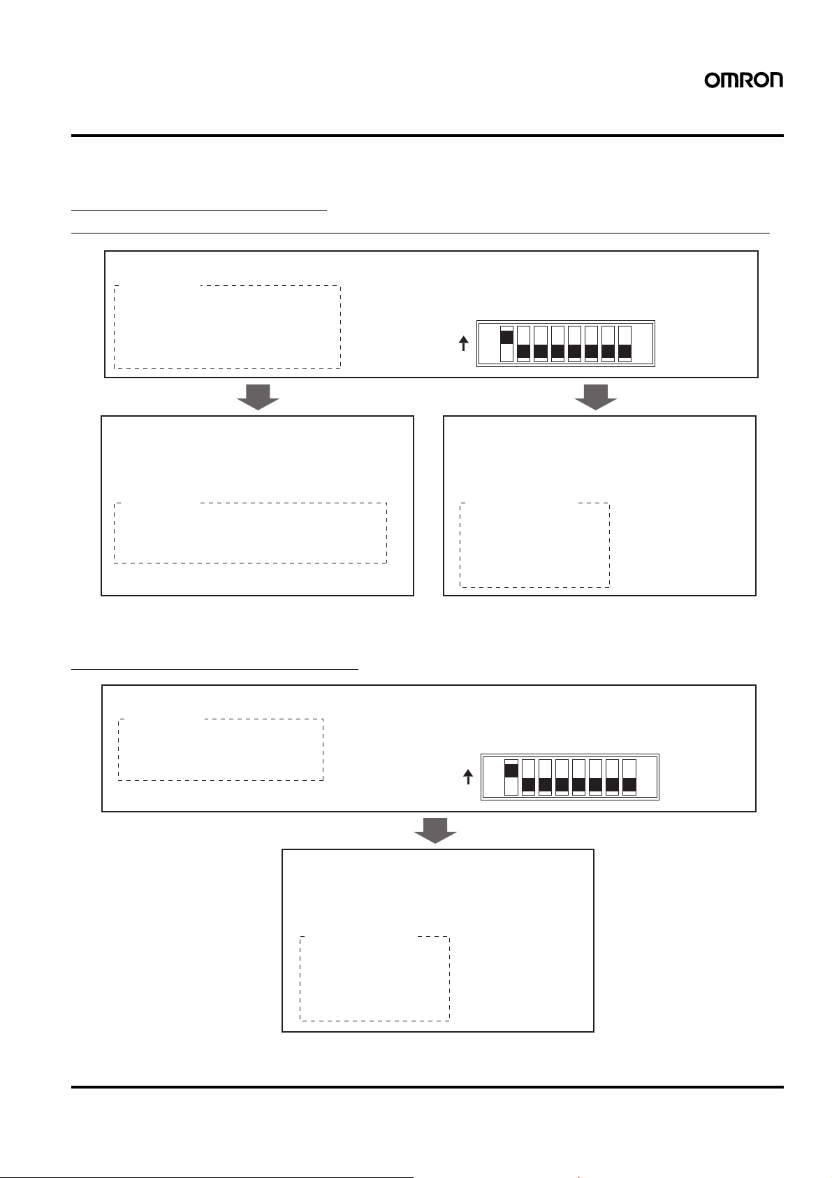
■Setting Procedure Guide
Setting for Counter Operation
(1-stage/2-stage Counter, Total and Preset Counter, Batch Counter, Dual Counter)
When Using Basic Settings Only
Basic Settings
• Counting speed (30 Hz, 5 kHz)
• Input mode (UP, DOWN)
• Output mode (N, F, C, K-1)
• One-shot output time (0.5 s, 0.05 s)(See note 2.)
• Reset input signal width (20 ms, 1 ms)
• NPN/PNP input mode (NPN, PNP)
The settings can be performed easily with the DIP switch.
➡
For details on the setting methods, refer to page 18.
12345678
ON
OFF
When Using Settings Other than the Above When Using Advanced Functions
All the functions can be set with the operation keys.
➡
For details on the setting methods, refer to page 19.
Other Settings Advanced Functions
• Input mode (UP/DOWN A, UP/DOWN B, UP/DOWN C)
• Output mode (R, P, Q, A, K-2, D, L, H)
• One-shot output time (except for 0.5 s and 0.05 s) (See note 2.)
Note: 1. At the time of delivery, the H7CX is set to the 1-stage counter (2-stage counter for H7CX-AW@/-A4W@ models) configuration.
2. Set to output 2 time when using as a 2-stage counter or batch counter.
Settings for advanced functions other than the basic
settings above can be performed with the operation keys.
For details on the setting methods, refer to page 19.
➡
• Dual count calculating mode
• Output 1 time (for 2-stage counter)
• Decimal point position
• Prescale value
• Display color
• Output allocation
• Key protect level
Setting for Tachometer Operation
When Using Basic Settings Only
Basic Settings
• Counting speed (30 Hz, 10 kHz)
• Output mode (HI-LO, AREA, HI-HI, LO-LO)
• Average processing (OFF, 2, 4, 8 times)
• NPN/PNP input mode (NPN, PNP)
The settings can be performed easily with the DIP switch.
➡
For details on the setting methods, refer to page 30.
12345678
ON
OFF
When Using Advanced Functions
Settings for advanced functions other than the basic
settings above can be performed with the operation keys.
For details on the setting methods, refer to page 31.
➡
Advanced Functions
• Decimal point position
• Prescale value
• Auto-zero time
• Startup time
• Display color
• Output allocation
• Key protect level
Note: At the time of delivery, the H7CX is set to the 2-stage counter (1-stage counter for H7CX-AU@ models) configuration.
Multifunction Preset Counter H7CX-A 17
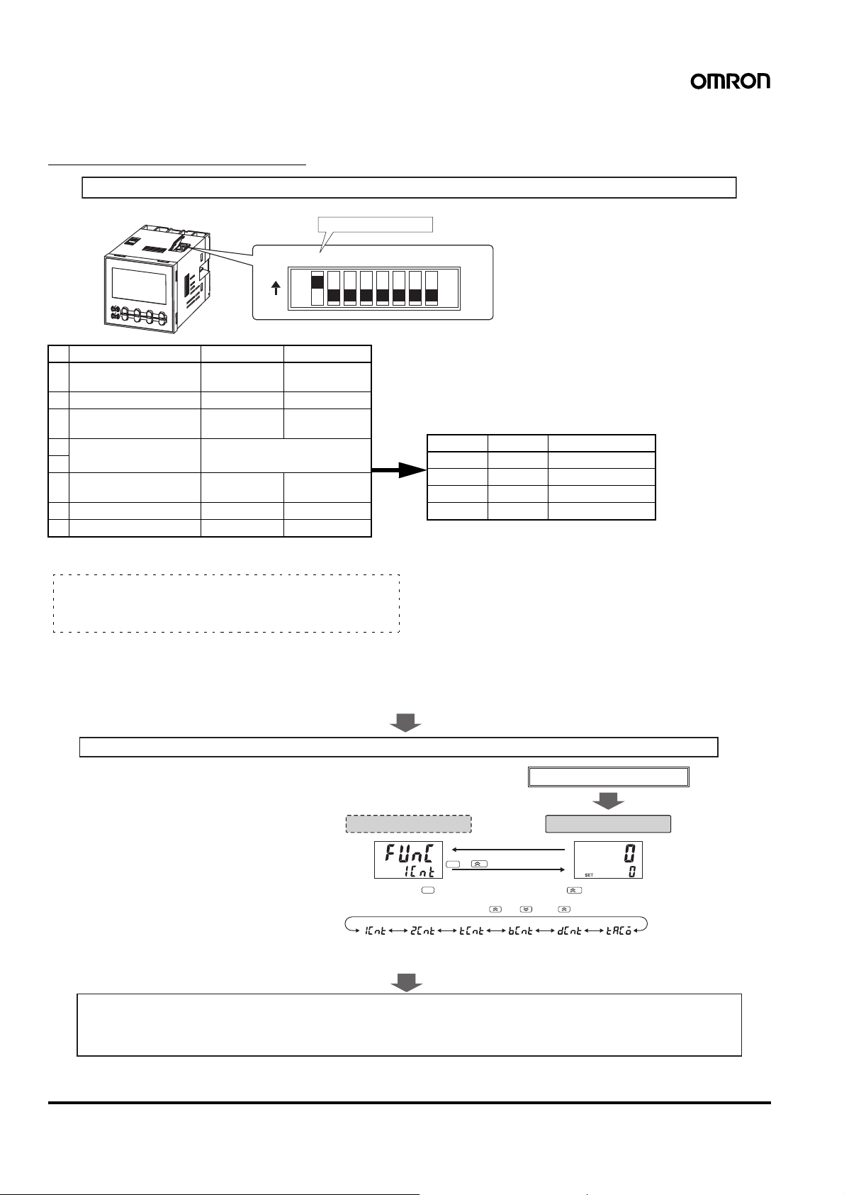
■Operating Procedures (Coun ter Function)
Settings for Basic Operations
Settings for basic functions can be performed with just the DIP switch.
Be sure to set pin 1 to ON.
12345678
ON
OFF
Note: All of the pins are factory-set to OFF.
Item OFF ON
1 DIP switch settings en-
able/disable
2 Counting speed 30 Hz 5 kHz
3 Input mode UP (increment) DOWN (decre-
4 Output mode Refer to the table on the right.
5
6 One-shot output time
(See note.)
7 Reset input signal width 20 ms 1 ms
8 NPN/PNP input mode NPN PNP
Note: Set to one-shot output 2 time when using as a 2-stage counter
or batch counter.
Easy Confirmation of Switch Settings Using Indicators
The ON/OFF status of the DIP switch pins can be
confirmed using the front display. For details, refer to page 36.
Note: 1. Be sure to set pin 1 of the DIP switch to ON. If it is set to OFF, the DIP switch settings will not be enabled.
2. Changes to DIP switch settings are enabled when the power is turned ON.
3. When setting input modes, output modes, or output times that cannot be set with the DIP s wit ch, all of the settings ha v e to be made using
the operation keys. For details on the setting methods, refer to page 19. When making settings using t he operation keys, be sure to se t
pin 1 of the DIP switch to OFF.
Disabled Enabled
ment)
0.5 s 0.05 s
Pin 4 Pin 5 Output mode
OFF OFF N
ON OFF F
OFF ON C
ON ON K-1
Switching to Total and Preset Counter, Batch Counter, and Dual Counter Operation (See note.)
The H7CX is factory-set to the 1-stage
counter (2-stage counter for H7CX-AW@/-
A4W@ models) configuration. To change to
a different configuration, use the procedure
shown on the right. For details, refer to
page 36.
Note: This includes changing to the 2-
stage counter (or 1-stage counter)
configuration.
Configuration selection mode
Hold down for
1
MODE
Note: The key must be pressed before the key.
Select the configuration using the and keys ( key with 6-digit models).
(1-stage
counter)
Note: The configurations that can be selected vary with the model.
MODE
(2-stage
counter)
(Total and
preset counter)
1 s min. (See note.)
+
(Batch
counter)
Advanced-Function Settings
After making DIP switch settings for basic operations, advanced functions (see note) can be added using the operation keys.
For details, refer to page 19.
Note: Advanced functions consist of the dual count calculating mode, output 1 time (for 2-stage counter), decimal point position, prescale value, display
color, output allocation, and key protect level.
1
(Dual
counter)
Power ON
Run mode
(Tachometer)
18 Multifunction Preset Counter H7CX-A (Counter Function)
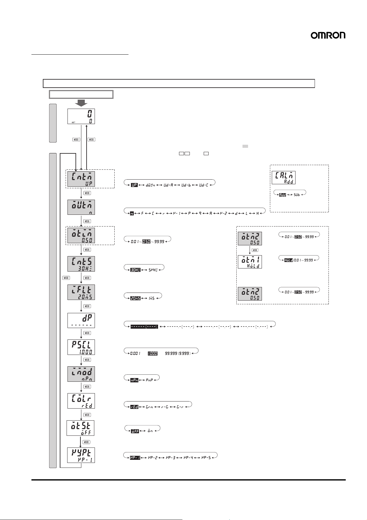
Settings for All Functions
Note: At the time of delivery, the H7CX is set to the 1-stage counter (2-stage count er for H7CX-AW@/-A4W@ models) configuration. When using
as a 2-stage (or 1-stage) counter, total and preset counter, batch counter, or dual counter, switch to the configuration using the procedure
given on page 36.
Settings that cannot be performed with the DIP switch are performed with the operation keys.
Power ON
Run mode
See note 1. See note 2.
3 s min.
3 s min.
Function setting mode
See note 3.
Input mode
Output mode
See note 6.
One-shot
output
time
Counting
speed
Reset input
signal
width
For details on operations and display in run mode, refer to page 22.
The display depends on the configuration used.
Note: 1. If the mode is switched to the function setting mode during operation, operation will con-
tinue.
2. Changes made to settings in function setting mode are enabled for the first time when the
mode is changed to run mode. Also, when settings are changed, the counter is reset
(present value initialized and output turned OFF) on returning to run mode.
The characters displayed in reverse video are the default settings.
When performing settings with operation keys only, set pin1 of the DIP switch to OFF (factory setting).
If pin 1 of the DIP switch is set to ON, the setting items indicated by will not be displayed.
Set each setting item using the keys. ( key only for 6-digit models)
See note 4.
See note 4.
(UP) (DOWN) (UP/DOWN A) (UP/DOWN B) (UP/DOWN C)
Note 4: Displayed for output modes other than K-2, D, L, and H only.
(N)
(F) (C) (R) (K-1) (P) (Q) (A) (K-2) (D) (L) (H)
Note: 5. Display only when the input mode is UP/DOWN A, B,
or C with 6-digit models (with H7CX-AU@/-AW@
models only for H).
(0.50s) (99.99s)(0.01s)
Note: Displayed only when the output mode is C, R, K-1, P,
Q, A, or K-2.
(30Hz) (5kHz)
(1ms)(20ms)
rr
r
Note 3:
When using as a dual counter:
(Addition) (Subtraction)
Note: Displayed only when the output
See note 5.
See note 5.See note 5.See note 5.
Note 6:
When using as a 2-stage counter:
When using as a
batch counter:
mode is K-2, D, L, or H.
Oneshot
output
Note: Displayed only when the
2 time
Oneshot
(Outputs held)
output
If the output time is 0.00, hold is
1 time
displayed.
Note 1: Displayed for output modes
Note 2: HOLD cannot be set when the
Oneshot
output
Note: Displayed only when the output
2 time
See note.
output mode is C, R, K-1,
P, Q, A, or K-2.
other than D, L, and H.
output mode is K-2.
mode is C, R, K-1, P, Q, A, or K-2.
Dual count
calculating mode
(0.50s) (99.99s)(0.01s)
(0.01s) (99.99s)
(0.50s) (99.99s)(0.01s)
Decimal
point
position
Prescale
value
NPN/PNP
input mode
Display color
Output
allocation
Key protect
level
See note 7.
No decimal
point
See note 7.
∼
(NPN
(PNP
input)
input)
(Red) (Green) (Red-green) (Green-red)
∼
One digit after
decimal point
(99.999) [9.999](1.000)(0.001)
Two digits after
decimal point
Three digits after
decimal point
Note 7: The displays for 4-digit models are shown inside
parentheses.
Note: Displayed for terminal-block models (except H7CX-A11@) only.
Note: Displayed for H7CX-AU@ models only.
(KP-1) (KP-2) (KP-3) (KP-4) (KP-5)
Multifunction Preset Count er H7CX-A (Counter Function) 19
Explanation of Functions
Input Mode (cntm) (Setting possible using DIP switch.)
Set increment mode (UP), decrement mode (D OWN), or one of the
increment/decrement modes (UP/DOWN A, UP/DOWN B, or UP/
DOWN C) as the input mode. Input modes other than UP or DOWN
modes cannot be set using the DIP switch and so use the operation
keys if other modes are required. (For details on the operation of the
input modes, refer to Input Modes and Present Value on page23.)
Dual Count Calculating Mode (calm)
When using as a dual counter, select either ADD (addition) or SUB
(subtraction) as the calculation method for the dual count value. SUB
mode can be used only when K-2, D, L, or H is selected as the output
mode with 6-digit models.
ADD: Dual count value = CP1 PV + CP2 PV
SUB: Dual count value = CP1 PV
− CP2 PV
Output Mode (outm) (Setting possible using DIP s witch.)
Set the way that control output for the present value is output. The
possible settings are N, F, C, R, K-1, P, Q, A, K-2, D, L, and H. Out put
modes other than N, F, C, or K-1 cannot be set using the DIP switch
and so use the operation keys if other modes are required. The output modes that can be set vary with the model. (For details on the
operation of the output modes, refer to Input/Output Mode Settings
on page 24.)
One-shot Output Time (otim) (Setting possible using DIP
switch.)
Set the one-shot output time (0.01 to 99.99 s) for control output.
One-shot output can be used only when C, R, K-1, P, Q, A, or K-2 is
selected as the output mode. Output times other than 0.5 s or 0.05 s
cannot be set with the DIP switch and so use the operation keys if
other settings are required.
One-shot Output 2 Time (otm2) (Setting possible using
DIP switch.)
When using as a 2-stage counter or batch counter, set the one-shot
output time (0.01 to 99.99 s) for control output (OUT2). One-shot output can be used only when C, R, K-1, P, Q, A, or K-2 is selected as
the output mode. Output times other than 0.5 s or 0.05 s cannot be
set with the DIP switch and so use the operation keys if other settings
are required.
One-shot Output 1 Time (otm1)
When using as a 2-stage counter, set the one-shot output time (0.01
to 99.99 s) for control output (OUT1). One-shot output can be used
only when D, L, or H is selected as the output mode. If the output
time is set to 0.00, hold is displayed, and outputs are held. HOLD
cannot be set when the output mode is K-2.
Counting Speed (cnts) (Setting possible using DIP
switch.)
Set the maximum counting speed (30 Hz/5 kHz) for CP1 and CP2
inputs together. If contacts are used for input signals, set the counting speed to 30 Hz. Processing to eliminate chattering is performed
for this setting.
Reset Input Signal Width (iflt) (Setting possible using
DIP switch.)
Set the reset input signal width (20 ms/1 ms) for reset/reset 1 and
total reset/reset 2 inputs together. If contacts are used for input signals, set the counting speed to 20 ms. Processing to eliminate chattering is performed for this setting.
Decimal Point Position (dp)
Decide the decimal point position for the present value, CP1/CP2
present values, set value (SV1, SV2), total count value, and dual
count set value.
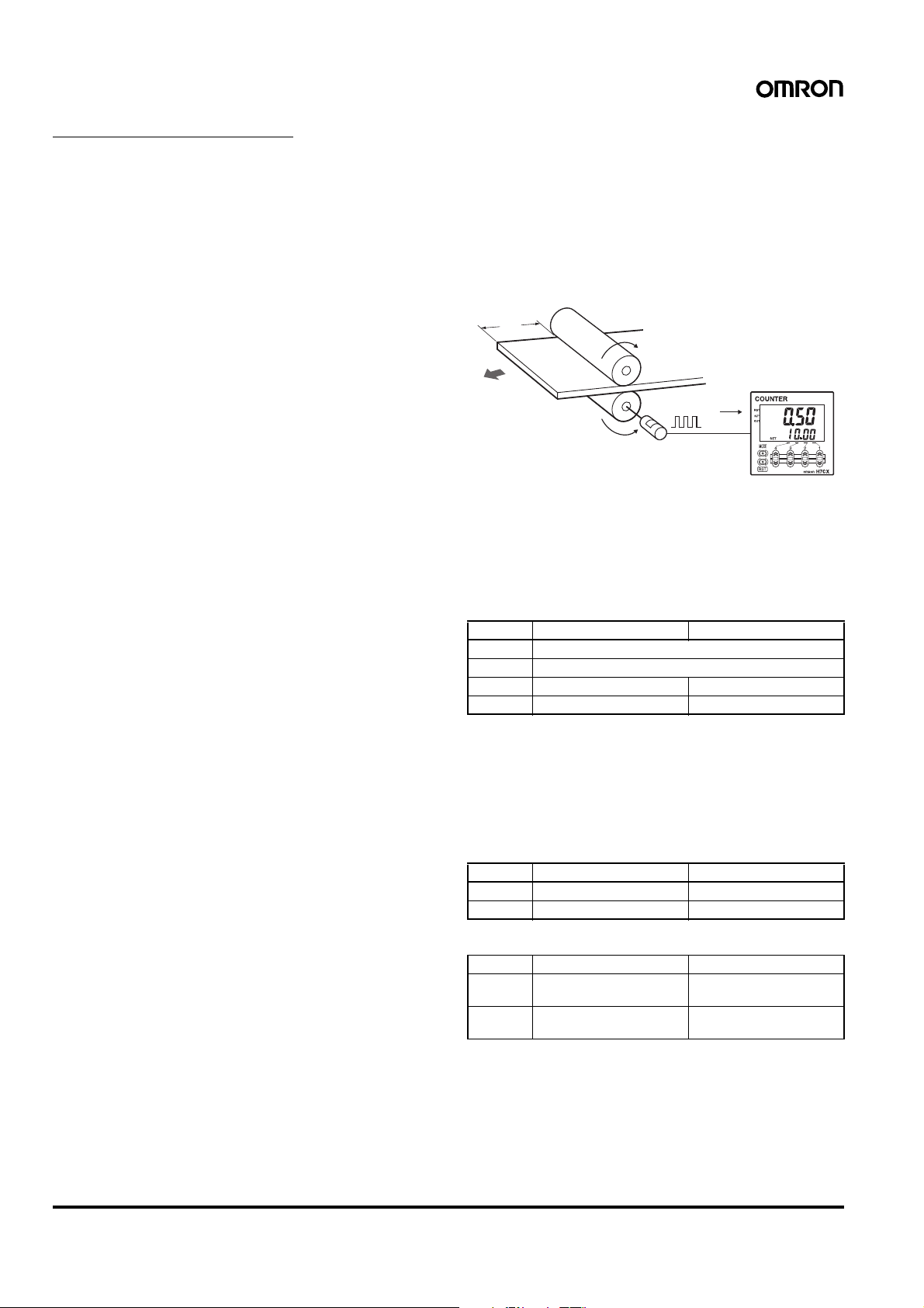
Prescale Value (pscl)
Pulses input to the counter are converted according to the specified
prescale value. (Setting range: 0.001 to 99.999 for 6-digit models
and 0.001 to 9.999 for 4-digit models.)
Example: To display the feed distance for systems that output
25 pulses for a feed length of 0.5 m in the form @@.@@ m:
1. Set the decimal point position to 2 decimal places.
2. Set the prescale value to 0.02 (0.5
0.5 m
Encoder
÷25).
25 pulses
NPN/PNP Input Mode (imod)
Select either NPN input (no-voltage input) or PNP input (voltage
input) as the input format. The same setting is used for all external
inputs. For details on input connections, refer to Input Connections
on page 11.
Display Color (colr)
Set the color used for the present value.
Output OFF (See note.) Output ON (See note.)
red Red (fixed)
grn Green (fixed)
r-g Red Green
g-r Green Red
Note: When using as a 2-stage counter, this is the status of output 2.
Output Allocation (otst)
When using H7CX-AU@ models as a 2-stage counter, the output can
be flexibly allocated to either stage 1 or 2.
Transistor output can be allocated to SV1 and contact output for SV2
or vice verse, as in the following table.
H7CX-AU/-AUD1
OUT1 OUT2
off Transistor (12-13) Contact (3, 4, 5)
on Contact (3, 4, 5) Transistor (12-13)
H7CX-AUSD1
OUT1 OUT2
off Transistor (12-13) Transistor with diode
on Transistor with diode
(3, 4, 5)
(3, 4, 5)
Transistor (12-13)
20 Multifunction Preset Counter H7CX-A (Counter Function)
Loading…