
Инструкция по подключению и программированию радиоприемника NICE OX2
Артикул: Как запрограммировать пульт NICE
ПОДРОБНЕЕ
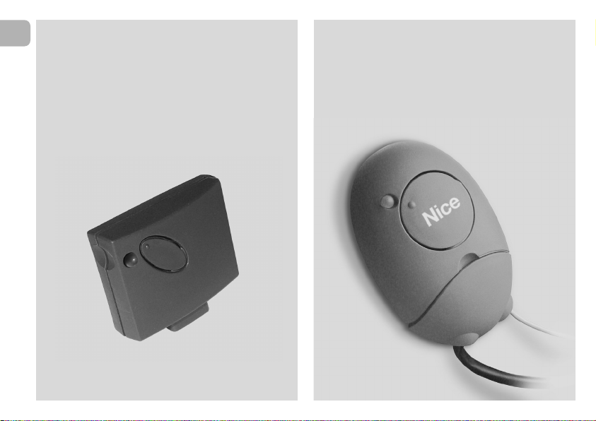
Внешний двухканальный приемник NICE OX2 является одним из приемников серии продуктов NiceOne, существуют различные модификации работающие на разных частотах (433 и 868 Мгц) и обладающие различнымии функциями.
Приемник NICE OX2 возможно подключить к автоматики для ворот или шлагбаумам разных производителей, что дает возможность управлять ими пультами дистанционного управления NICE.
Приемник NICE OXI поддерживает возможность работаты с пультами NICE разных серий. Первый записанный пульт определяет возможность приемника запоминать последующие. Возможно записывать пульты серии FLO, FLOR, O-CODE, TTS или SMILO. При отсутвии рабочего, ранее записанного в память приемника пульта, определить кодировку которую поддерживает данный приемник, можно по количеству вспышек зеленого светодиода расположенного на приемнике. Для этого необходимо выключить и включить питание блока управления, после включения питания светодиод зеленого цвета моргнет 1, 2, 3 или 5 раз. Что соответсвует:
1 вспышка — кодировка пультов серии FLO (фиксированный код)
2 вспышки — кодировки пультов серии FLOR, O-CODE или TTS (динамический код)
3 вспышки — кодировка пультов серии SMILO
5 вспышек — память.
Приемник имеет несколько режимов программирования в том числе и дистанционный. Для дистанционного программирования необходим рабочий пульт ранее записанный в приемник NICE OXI в 1 или 2 режимах, дополнительный пульт будет записан дистанционно в таком же режиме, и обладать такими же функциями как и ранее записанный. Процедура дистанционного программирования дополнительных пультов производиться в радиусе действия приемника (10-20 метров от блока управления).
Порядок действий при дистанционном программировании дополнительного пульта:
1. Нажать и удерживать нажатой в течении более 5 секунд любую кнопку НОВОГО пульта.
2. Три раза по 1 секунде нажать и отпустить на кнопку РАБОЧЕГО пульта открывающую ворота или шлагбаум.
3. Один раз на 1 секунду нажать на кнопку НОВОГО пульта.
4. Если необходимо записать насколько дополнительных пультов, повторите 1-3 пункты для записи последующих пультов.
С полной инструкцией NICE OX2 можно ознакомиться или скачать по ссылке ниже.

EN — Instructions and warnings for
installation and use
IT — Istruzioni ed avvertenze per
l’installazione e l’uso
FR — Instructions et avertissements
pour l’installation et l’utilisation
ES — Instrucciones y advertencias
para la instalación y el uso
DE — Installierungs-und Gebrauchs-
anleitungen und Hinweise
PL — Instrukcje i ostrzeżenia do
instalacji i użytkowania
NL — Aanwijzingen en aanbevelingen
voor installatie en gebruik
NiceOne
Receiver
OXI family
OX2 family
Europe: 0682

EN- Integration to manual
IT — Integrazione al manuale
FR — Addenda au guide
ES — Integración del manual
DE- VervollstŠndigung des Handbuchs
PL — Uzupełnienie do instrukcji
NL — Aanvulling op de handleiding
ENGLISH — List of commands available with OXI receiver and transmitters memorised in “Extended Mode II”:
Output
1
2
3
4
5
6
7
8
9
10
11
12
13
14
15
Command
Step by step
Partial opening 1
Open
Close
Stop
Apartment block Step by Step
Step by Step high priority
Partial open 2
Partial open 3
Open and block automation
Close and block automation
Block automation
Release automation
Courtesy light timer on
Courtesy light on-off
Description
“S.S.” (Step by Step) command
“Partial opening 1” command
“Open” command
“Close” command
Stops manoeuvre
Apartment block control
Run and Robus 400/600/1000: Gives command even when automation is blocked or commands are in progress
Soon: Gives command even when automation is blocked
“Partial opening 2” command (programmable with Oview)
“Partial opening 3” command (programmable with Oview)
It causes an opening manoeuvre, after which the automation is blocked; the control unit accepts no further commands with the exception of “Step by
step high priority”, “Release” automation and (from Oview only) the commands “Release and close” and “Release and open”
It causes a closure manoeuvre, after which the automation is blocked; the control unit accepts no further commands with the exception of “Step by
step high priority”, “Release” automation and (from Oview only ) the commands “Release and close” and “Release and open”
It causes the manoeuvre to stop and the automation to block; the control unit accepts no further commands with the exception of “Step by step high
priority”, “Release” au to mation and (from Oview only ) the commands “Release and close” and “Release and open”.
It causes the automation to be released and normal operation to resume
The Courtesy light comes on with timed turning off
The Courtesy light turns on and off in step-by-step mode
ITALIANO — Elenco dei comandi disponibili con ricevitore OXI e trasmettitori memorizzati in “Modo II esteso”:
Uscita
1
2
3
4
5
6
7
8
9
10
11
12
13
14
15
Comando
Passo-Passo
Apertura parziale 1
Apre
Chiude
Stop
Passo-Passo Condominiale
Passo-Passo alta priorità
Apre parziale 2
Apre parziale 3
Apre e Blocca automazione
Chiude e Blocca automazione
Blocca automazione
Sblocca automazione
On Timer Luce di Cortesia
On-Off Luce di Cortesia
Descrizione
Comando “P.P.” (Passo-Passo)
Comando “Apertura parziale 1”
Comando “Apre”
Comando “Chiude”
Arresta la manovra
Comando in modalità Condominiale
Run e Robus 400/600/1000: Comanda anche con automazione bloccata o comandi attivi — Soon: Comanda anche con automazione bloccata
Comando “Apertura parziale 2” (programmabile con Oview)
Comando “Apertura parziale 3” (programmabile con Oview)
Provoca una manovra di apertura e al termine di questa il blocco dell’automazione; la centrale non accetta nessun altro comando ad eccezione di
“Passo passo alta priorità”, “Sblocca” automazione oppure (solo da Oview) i comandi: “Sblocca e chiude” e “Sblocca e apre”
Provoca una manovra di chiusura e al termine di questa il blocco dell’automazione; la centrale non accetta nessun altro comando ad eccezione di
“Passo passo alta priorità”, “Sblocca” automazione oppure (solo da Oview) i comandi: “Sblocca e chiude” e “Sblocca e apre”
Provoca una fermata della manovra ed il blocco dell’automazione; la centrale non accetta nessun altro comando ad eccezione di “Passo passo alta
priorità”, “Sblocca” automazione oppure (solo da Oview) i comandi: “Sblocca e chiude” e “Sblocca e apre”
Provoca lo sblocco dell’automazione ed il ripristino del normale funzionamento
Si accende l’uscita Luce di cortesia con spegnimento temporizzato
Si accende e spegne l’uscita Luce di cortesia in modalità passo-passo
FRANÇAIS — Liste des commandes disponibles avec récepteur OXI et émetteurs mémorisés en « Mode II étendu » :
Sortie
1
2
3
4
5
6
7
8
9
10
11
12
13
14
15
Commande
Pas à pas
Ouverture partielle 1
Ouverture
Fermeture
Stop
Pas à pas collectif
Pas à pas haute priorité
Ouverture partielle 2
Ouverture partielle 3
Ouverture et blocage de
l’automatisme
Fermeture et blocage de
l’automatisme
Blocage de l’automatisme
Déblocage de l’automatisme
Activation temporisateur
clairage automatique
Marche — Arrêt éclairage
automatique
Description
Commande « PP » (pas à pas)
Commande « Ouverture partielle 1 »
Commande « Ouverture »
Commande « Fermeture »
Arrête la manœuvre
Commande en modalité Fonctionnement collectif
Run et Robus 400/600/1000: Commande aussi avec automatisme bloqué ou commandes actives — Soon: Commande aussi avec automatisme bloqué
Commande « Ouverture partielle 2 » (programmable avec Oview)
Commande « Ouverture partielle 3 » (programmable avec Oview)
Provoque une manœuvre d’ouverture et à la fin de celle-ci le blocage de l’automatisme ; la logique n’accepte aucune autre commande à l’exception
de « Pas à pas haute priorité », « Déblocage de l’automatisme » ou (uniquement avec Oview) les commandes : « Déblocage et fermeture » et « Déblocage et ouverture »
Provoque une manœuvre de fermeture et à la fin de l’automatisme ; la logique n’accepte aucune autre commande à l’exception de « Pas à pas haute
priorité », « Dé blocage de l’automatisme » ou (uniquement avec Oview) les commandes : « Déblocage et fermeture » et « Déblocage et ouverture »
Provoque un arrêt de la manœuvre et le blocage de l’automa tisme ; la logique n’accepte aucune autre commande à l’ex ception de « Pas à pas haute
priorité », « Déblocage de l’au tomatisme » ou (uniquement avec Oview) les commandes : « Déblocage et fermeture » et « Déblocage et ouverture »
Provoque le déblocage de l’automatisme et le rétablissement du fonctionnement normal
Allumage de la sortie Éclairage automatique avec extinction temporisée
Allumage et extinction de la sortie Éclairage automatique en modalité pas à pas

IST314.4858 Rev. 00 – 01-10-2009
ESPAÑOL — Lista de los mandos disponibles con receptor OXI y transmisores memorizados en “Modo II amplio”:
Salida
1
2
3
4
5
6
7
8
9
10
11
12
13
14
15
Mando
Paso a Paso
Apertura parcial 1
Abrir
Cerrar
Stop
Paso a Paso Comunitario
Paso a Paso prioridad alta
Abrir parcial 2
Abrir parcial 3
Abrir y Bloquear automatización
Cerrar y Bloquear
automatización
Bloquear automatización
Desbloquear automatización
On Timer Luz de cortesía
On-Off Luz de cortesía
Descripción
Mando “P.P.” (Paso a Paso)
Mando «Apertura parcial 1»
Mando “Abrir”
Mando “Cerrar”
Detiene el movimiento
Mando en modalidad Comunitaria
Run y Robus 400/600/1000: Acciona incluso con la automatización bloqueada o con los mandos activos
Soon: Acciona incluso con la automatización bloqueada
Mando “Apertura parcial 2” (programable con Oview)
Mando “Apertura parcial 3” (programable con Oview)
Provoca un movimiento de apertura y al final de éste provoca el bloqueo del automatismo; la central no acepta ningún otro mando salvo “Paso a paso
prioridad alta”, “Desbloquear” automación o bien (sólo desde Oview) los mandos: “Desbloquear y cerrar” y “Desbloquear y abrir”
Provoca un movimiento de cierre y al final de éste provoca el bloqueo del automatismo; la central no acepta ningún otro mando salvo “Paso a paso
prioridad alta”, “Desbloquear” automación o bien (sólo desde Oview) los mandos: “Desbloquear y cerrar” y “Desbloquear y abrir”
Provoca una parada del movimiento y el bloqueo del automatismo; la central no acepta ningún otro mando salvo “Paso a paso prioridad alta”, “Desbloquear” automación o bien (sólo desde Oview) los mandos: “Desbloquear y cerrar” y “Desbloquear y abrir”.
Provoca el desbloqueo del automatismo y el restablecimiento del funcionamiento normal
Se enciende la salida Luz de cortesía con apagado temporizado
Se enciende y apaga la salida Luz de cortesía en modalidad paso a paso
DEUTSCH — Liste der verfügbaren Steuerungen mit Empfänger OXI und Sender, die im “erweiterten Modus II” gespeichert sind:
Ausgang
1
2
3
4
5
6
7
8
9
10
11
12
13
14
15
Steuerung
Schrittbetrieb
Teilöffnung 1
Öffnen
Schließt
Stopp
Schrittbetrieb Wohnblock
Schrittbetrieb Hohe Priorität
Teilöffnung 2
Teilöffnung 3
Öffnen und sperren
Automatisierung
Schließt und Blockiert die
Automatisierung
Blockiert die Automatisierung
Löst die Automatisierung
On Timer zusätzliche Beleuchtung
On-Off zusätzliche Beleuchtung
Beschreibung
Befehl “P.P.” (Schrittbetrieb)
Steuerung “Teilöffnung 1”
Befehl “Öffnet”
Befehl “Schließt”
Stoppt die Bewegung
Steuerung im Wohnblockmodus
Run und Robus 400/600/1000: Steuert auch bei blockierter Automatisierung oder aktive Steuerungen — Soon: Steuert auch bei blockierter Automatisierung
Steuerung “Teilöffnung 2” (mit Oview programmierbar)
Steuerung “Teilöffnung 3” (mit Oview programmierbar)
Ruft eine Öffnungsbewegung hervor und am Ende dieser die Blockierung der Automatisierung; die Steuerung akzeptiert keine andere Steuerung,
außer “Schrittbetrieb hohe Priorität”, “Lösen” Automatisierung oder (nur aus Oview) der Steuerungen: “Löst und schließt” und “Löst und öffnet”
Ruft eine Schließbewegung hervor und am Ende dieser die Blockierung der Automatisierung; die Steuerung akzeptiert keine andere Steuerung, außer
“Schrittbetrieb hohe Priorität”, “Lösen” Automatisierung oder (nur aus Oview) der Steuerungen: “Löst und schließt” und “Löst und öffnet”
Ruft einen Bewegungsstopp hervor und am Ende dieser die Blockierung der Automatisierung; die Steuerung ak zeptiert keine andere Steuerung,
außer “Schrittbetrieb ho he Priorität”, “Lösen” Automatisierung oder (nur aus Ovi ew) der Steuerungen: “Löst und schließt” und “Löst und öffnet”
Ruft die Blockierung der Automatisierung und die Wiederherstellung des normalen Betriebs hervor
Der Ausgang zusätzliche Beleuchtung mit zeitgeregelter Abschaltung wird erleuchtet
Der Ausgang zusätzliche Beleuchtung im Schrittbetrieb wird erleuchtet und ausgeschaltet
POLSKI — Wykaz poleceń dostępnych z zastosowaniem odbiornika OXI i nadajników wczytanych w “Trybie II poszerzonym”:
Wyjście
1
2
3
4
5
6
7
8
9
10
11
12
13
14
15
Polecenie
Krok po Kroku
Otwarcie częściowe 1
Otwarcie
Zamknięcie
Stop
Krok po kroku w bloku mieszkalnym
Krok po kroku z dużym priorytetem
Otwarcie częściowe 2
Otwarcie częściowe 3
Otwarcie i Zablokowanie
automatyki
Zamknięcie i Zablokowanie
automatyki
Zablokowanie automatyki
Odblokowanie automatyki
Włączenie timera światełka
nocnegon
Włączenie-Wyłączenie
światełka nocnego
Opis
Polecenie “K.K.” (Krok po kroku)
Polecenie “Otwarcie częściowe 12
Polecenie “Otwarcie”
Polecenie “Zamknięcie”
Zatrzymanie manewru
Działanie w trybie “bloku mieszkalnego”
Run i Robus 600/1000: Steruje również w przypadku zablokowania automatyki lub uaktywnienia poleceń
Soon: Steruje również w przypadku zablokowania automatyki
Polecenie “Otwarcie częściowe 2” (programowalne z pomocą Oview)
Polecenie “Otwarcie częściowe 3” (programowalne z pomocą Oview)
Powoduje wykonanie manewru otwarcia a po jego za koń c zeniu zablokowanie automatyki; centrala nie akceptuje żadne go innego polecenia za
wyjątkiem “Krok po kroku z du żym pri orytetem”, “Odblokuj” lub (tylko z Oview) nastę pujące po le cenia: “Odblokowanie i zamknięcie” i “Odblokowanie i otwarcie”
Powoduje wykonanie manewru zamknięcia a po jego zakończeniu zablokowanie automatyki; centrala nie akceptuje żadnego innego polecenia za
wyjątkiem “Krok po kroku z dużym priorytetem”, “Odblokuj” lub (tylko z Oview) na stępujące polecenia: “Odblokowanie i zamknięcie” i “Od blo kowanie i otwarcie”
Powoduje zatrzymanie manewru i zablokowanie automatyki; centrala nie akceptuje żadnego innego polecenia za wyjątkiem “Krok po kroku z dużym
priorytetem”, “Odblokuj” lub (tylko z Oview) następujące polecenia: “Odblokowanie i zamknięcie” i “Odblokowanie i otwarcie”
Powoduje odblokowanie automatu i przywrócenie zwy kłego funkcjonowania
Włącza się wyjście “światełko nocne”, którego wyłączanie jest regulowane timerem
Wyjście “światełko nocne” włącza się i wyłącza w trybie “krok po kroku”
NEDERLANDS — Lijst van instructies die beschikbaar zijn met de ontvanger OXI en zenders die zijn opgeslagen in “Modus II uitgebreid”:
Uitgang
1
2
3
4
5
6
7
8
9
10
11
12
13
14
15
Instructie
Stap-voor-stap
Gedeeltelijke opening 1
Open
Sluit
Stop
Stap-voor-stap woonblok
Stap-voor-stap hoge prioriteit
Open gedeeltelijk 2
Open gedeeltelijk 3
Open en blokkeer
Sluit en blokkeer automatisering
Blokeer automatisering
Deblokkeer automatisering
On Timer gebruikerslicht
On-Off gebruikerslicht
Beschrijving
Instructie “P.P.” (Stap-voor-stap)
Instructie “Gedeeltelijke opening 1”
Instructie “Open”
Instructie “Sluit”
Stop de manoeuvre
Instructie in modus Woonblok
Run en Robus 400/600/1000: stuurt ook aan bij geblokkeerde automatisering of actieve instructies — Soon: stuurt ook aan bij geblokkeerde automatisering
Instructie “Open gedeeltelijk 2” (programmeerbaar met Oview)
Instructie “Open gedeeltelijk 3” (programmeerbaar met Oview)
Veroorzaakt een openingsmanoeuvre en na afloop daarvan de blokkering van de automatisering; de besturingseenheid accepteert geen enkele andere instructie met uitzondering van “Stap-voor-stap hoge prioriteit”, “Deblokkeer automatisering” of (alleen vanaf Oview) de instructies: “Deblokkeer en
sluit” en “Deblokkeer en open”
Veroorzaakt een sluitmanoeuvre en na afloop daarvan de blokkering van de automatisering; de besturingseenheid accepteert geen enkele andere
instructie met uitzondering van “Stap-voor-stap hoge prioriteit”, “Deblokkeer automatisering” of (alleen vanaf Oview) de instructies: “Deblokkeer en
sluit” en “Deblokkeer en open”
Veroorzaakt een stop van de manoeuvre en de blokkering van de automatisering; de besturingseenheid accepteert geen enkele andere instructie met
uitzondering van “Stap-voor-stap hoge prioriteit”, “Deblokkeer automatisering” of (alleen vanaf Oview) de instructies: “Deblokkeer en sluit” en
“Deblokkeer en open”.
Veroorzaakt de deblokkering van de automatisering en de hervatting van de normale werking
De uitgang Gebruikerslicht gaat aan, met tijdgeprogrammeerde uitschakeling
De uitgang Gebruikerslicht gaat aan en uit, in de modus Stap-voor-stap
2
EN
EN – Models with “SM” type connection
IT – Modelli con connessione a innesto “SM”
FR – Modèles avec connecteur embrochable «SM»
ES – Modelos con conexión con conector “SM”
DE – Modelle mit Steckverbindung “SM”
PL – Modele z połączeniem za pomocą złącza
typu “SM”
NL – Modellen met steekconnector “SM”
EN – Models with universal type connection
IT – Modelli con connessione universale
FR – Modèles avec connecteur universel
ES – Modelos con conexión universal
DE – Modelle mit Universalverbindung
PL – Modele z połączeniem uniwersalnym
NL – Modellen met universele aansluiting

ENGLISH
Original instructions
1 – PRODUCT DESCRIPTION AND
INTENDED USE
This receiver is part of the series “NiceOne” produced by Nice
spa. The receivers in this series are destined for use on the
control units fitted on systems for the automation of gates,
garage doors and road barriers. Any use other than as
specified herein is to be considered improper and is
strictly prohibited! The manufacturer denies all liability for
damage deriving from improper use of the product and
use other than as specified in this manual.
Various models are available, with the specifications as stated
in the table below.
1.1 – The “NiceOpera” system
The receivers in the series NiceOne are part of the “NiceOpera” system. This system has been designed to simplify
the programming phases, use and maintenance of the de vices normally used in automation systems. The system comprises various software and hardware devices capable of
intercommunicating via radio, by means of the “O-Code”
encoding system or a “physical” connection via cable.
The main devices that make up the NiceOpera system are:
– NiceOne transmitters;
– NiceOne receivers;
– O-box programming unit;
– Control units and gearmotors with “T4 Bus”;
– O-View programmer for devices with “T4 Bus”.
IMPORTANT – For further details on all functions of the
NiceOpera system and interdependency of the various
devices in the system, refer to the general manual “NiceOpera System Book”, also available on the Internet site
www.niceforyou.com.
EN
Mod. Frequency Function Connection
OXI 433.92 MHz Receiver Connector type
OXIFM 868.46 MHz Receiver Connector type
OXIT 433.92 MHz Receiver-transmitter Connector type
OXITFM 868.46 MHz Receiver-transmitter Connector type
OX2 433.92 MHz Receiver with 6-core cable
OX2FM 868.46 MHz Receiver with 6-core cable
OX2T 433.92 MHz Receiver-transmitter with 6-core cable
OX2TFM 868.46 MHz Receiver-transmitter with 6-core cable
Notes to table:
– The frequencies 433.92
MHz and 868.46 MHz are
not compatible.
– The letter “T” in the model
name indicates a receiver with
built-in transmitter.
3

4
EN
2 – FUNCTIONAL PRODUCT
SPECIFICATIONS
• For all models
– The receiver manages “O-Code” radio encoding with vari-
able code (rolling-code), which enables use of all the new
functions in the NiceOpera system.
The receiver is compatible also with “FloR”, “TTS”, “Smilo”
and “Flo” encoding systems. However, in this case some of
the exclusive NiceOpera system functions described in
this manual cannot be used.
– The receiver has a capacity of 1024 spaces in which to
memorise transmitters. If the transmitter is memorised in
“Mode I”, all the relative keys
will occupy 1 memory alloca-
tion; otherwise if memorised in “Mode II”, each memorised
key will occupy 1 memory allocation (for memorisation pro-
cedures, see below in this manual).
– Each receiver has its own identification number
called a
“Certificate”.
This number enables access to a series of operations, such
as: Memorisation of new transmitters without the need for
direct intervention on the receiver and use of the O-View
unit, by means of the “T4 Bus” connection.
The sealed coupon in the product pack contains the sheet
with the certificate number of this receiver. Caution! – this
coupon must be kept in a safe place as it enables access to
data stored in the receiver, unless further protection measures are adopted, such as the use of a security password.
• For models with “SM” type connection
– These models can be used exclusively with the control units
fitted with an “SM” type connection (fig. 1). Note – to identify
compatible control units, refer to the Nice product catalogue.
– These models automatically recognise the characteristics of
the control unit to which they are connected and the receiver self-installs as follows.
• If the control unit manages the “T4 Bus
”, the receiver
provides up to 15 different commands.
• If the control unit does not manage the “T4 Bus
”, the
receiver provides up to 4 different command channels.
Caution! – In both cases the number and variety of the
commands available depend on the type and model of control unit used. The “Table of commands” of each control unit
is provided in the instruction manual of the relative control
unit.
• For models with universal type connection
– These models operate with 2 voltage-free contact relays
and therefore can be used with any type of control unit.
• For models with “T” in the model name
– These models are equipped with a “Repeater” function (see
below in this manual) which enables an increase in the trans-
mission range of the transmitters. They also enable “wireless”
communication with the O-Box programming unit.

3 – PRODUCT INSTALLATION
• For models with “SM” type connection
These models are connected to the control unit by inserting
the connector in the relative control unit connector (fig. 1).
Caution! – Before connecting or removing the receiver,
disconnect the control unit from the power supply.
The aerial supplied must also be installed, connecting it to the
specific terminals on the control unit.
• For models with universal type connection
––– Power supply selection –––
These models are connected to the control unit by means of a
6-core cable. Before connecting the cable, select the type of
power supply required, leaving or removing the electric jumper
as necessary (fig. 2-a) as follows:
1
– Jumper NOT inserted
(voltage limits: 18 ÷ 28 V)
– Jumper INSERTED
(voltage limits: 10 ÷ 18 V)
2
a
= 24 V ac/dc
EN
= 12 V ac/dc
IT
5

6
EN
––– Electrical connections –––
Connect the 6 wires of the receiver cable to the relative terminals of the control unit as follows (fig. 3):
•Redand Black = POWER SUPPLY
(red = Positive, black = Negative. In AC this is not important).
• White and White = RELAY 1 OUTPUT
(voltage-free contact of a normally open relay).
• Purple and Purple = RELAY 2 OUTPUT
(voltage-free contact of a normally open relay).
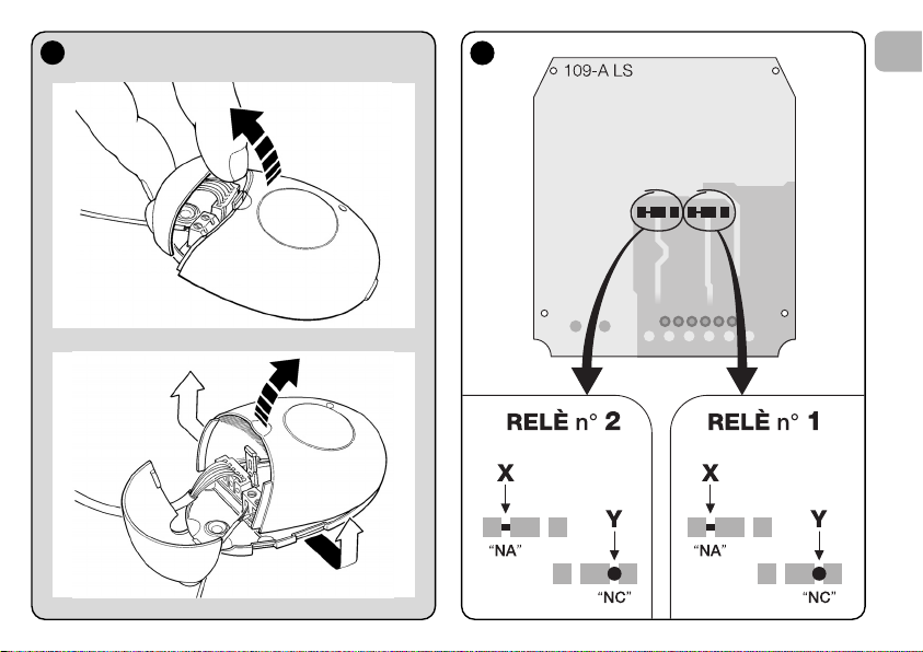
–– How to obtain “
NC” type contacts ––
The outputs are controlled by 2 relays with NO (normally open)
type contact. To change to NC (normally closed) type contact,
proceed as follows:
01. Disconnect the receiver from the power supply.
02. Open the box of the receiver by first raising the smaller
section of the cover (fig. 4-a) and then the larger section
with the key (fig. 4-b).
03. Carefully remove the board and turn it over: the side with
the soldered elements must be facing the user.
04. On the side with the soldered elements, proceed as fol-
lows (fig. 5):
– Cut the traced section at point “X”
– Join the contacts with a drop of tin at points “Y”.
Note – these modifications may be applied to one or
both relays as required.
3
Red
Black
White
White
Purple
Purple
a
4
5
EN
a
b
7

8
EN
• For all models:
Installation of an external aerial
If the aerial supplied is in an unfavourable position and the
radio signal is weak, an external aerial may be installed to
improve reception (mod. ABF or ABFKIT). The new aerial must
be positioned as high as possible and above any metal or
reinforced concrete structures present in the area.
– Connection to the Control Unit
: Use a coaxial cable with
an impedance of 50 ohm (for example, a RG58 cable with
low loss). Caution! – To reduce signal dispersion use a
cable that is as short as possible (not exceeding 10 m).
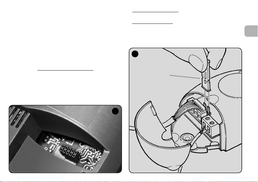
– Connection to the receiver
(only for models with univer-
sal type connection): Open the receiver by first raising the
smaller section of the cover (fig. 4-a) and disconnect the
aerial supplied; then connect the cable of the new aerial to
terminal 1 and 2 as follows (fig. 3—a): Terminal 1 = sheath;
Terminal 2 = core.
6
Programming warnings
The settings described in this chapter (except for procedure 6) require use of the key and led on the receiver (fig.
6). To indicate the state of activity in progress, the led
emits a set number of flashes with a specific duration and
colour (green, red or orange). For the meaning of these
signals, refer to Table A at the end of the manual.
PROGRAMMING THE
MAIN FUNCTIONS
Led Key
Led Key

4 – CAUTION! – READ THIS SECTION
BEFORE MEMORISING THE
TRANSMITTER
The receiver can only memorise transmitters belonging to one
of the following 3 encoding families
– family with “O-Code”, “FloR” and “TTS” encoding;
– family with “Flo” encoding;
– family with “Smilo” encoding.
Note – Each code enables use exclusively
associated functions on the receiver.
Caution! – The encoding family
memorised on the receiver also defines the relative
encoding family for the subsequent transmitters to be
memorised.
To change the encoding family
procedure 10 – Total receiver memory deletion.
To check on the receiver whether transmitters and the associated encoding family
lows:
01. Disconnect the receiver from the power supply.
02. Re-connect the power to the receiver and count the
number of green flashes emitted by the receiver led.
03. Check the number of flashes emitted with the data in the
table below:
– 1 flash = Flo encoding
– 2 flashes = O-Code / FloR / TTS encoding
– 3 flashes = Smilo encoding
– 5 flashes = no transmitter entered
are already memorised, proceed as fol-
:
of the standard
of the first transmitter
set on the receiver, perform
Caution! – Before memorising a transmitter, carefully
read all memorisation procedures described below to
select the one most suited to your specific application.
5 – TRANSMITTER MEMORISATION
PROCEDURE: “Mode I” AND “Mode II”
Each control unit has a set number of commands that can be
activated according to the type of receiver: The models with
“SM” connector provide 4 or 15 commands while models
with the universal connection provide 2 outputs.
In general the commands can be associated with the transmitter keys in two ways:
Mode I”. This mode enables memorisation on the receiver
• “
of all transmitter keys
mitters with more than one identity code such as model ON9).
The keys are automatically
mands of the control unit or the receiver outputs, on models
with universal connectotion.
Mode II”. This mode enables memorisation on the receiv-
• “
er of a single transmitter key
which command, among those available on the control unit
(maximum 4) or which output of the receiver to be associated
with the selected key.
– “Extended Mode II”
This mode can only be used with control units using the connection system “T4 Bus”. The “Extended Mode II” is the same
as “Mode II” with the additional option to choose the required
command from those available in the “Table of commands”
(maximum 15), as provided in the manual of the control unit
connected to the receiver.
or a group of the latter at once (on trans-
associated with the pre-set com-
. The user has a free choice of
(only for models with “SM” connector).
EN
9

10
EN
5.1 – Memorisation in “MODE I”
Warning – This procedure simultaneously memorises all
keys of the transmitter or a group of the latter (on transmitters with more than one identity code).
01. Press and hold the key on the receiver until the green led
on the receiver illuminates. Then release the key.
02. (within 10 seconds) On the transmitter to be memorised,
press and hold any key until the led on the receiver emits
the first of 3 green flashes to confirm memorisation.
Note – After the three flashes, a 10-second interval is available to memorise another transmitter as required.
5.2 – Memorisation in “MODE II”
(valid also for “Extended Mode II”)
WARNINGS:
– The “Extended Mode II” procedure can only be used
with receivers with “SM” type connectors.
– This procedure enables memorisation of a single trans
—
mitter key.
01. In the control unit manual, look up the “Table of com-
mands”, select the command to assign to the transmitter
key and note the number corresponding to the command.
02. (on the receiver) Press the key the same number of times
as the previously noted number – the Led on the receiv-
er emits the same number of flashes repeated at regular
intervals.
03. (on the transmitter within 10 seconds) Press and hold the
selected key for memorisation until the led on the receiver emits the first of 3 flashes (= memorisation confirmed).
Note – After the three flashes, a 10-second interval is available to memorise the same command on other keys on the
same transmitter or a new transmitter as required.
6 – MEMORISING A TRANSMITTER USING
THE “ENABLE CODE
” OF ANOTHER
TRANSMITTER
[already memorised]
This procedure can only be used if two transmitters with
“O-Code” encoding are used.
The NiceOne transmitters have a secret code
stored in the
memory, known as the “ENABLE CODE”. Thanks to this
code, operation of NEW transmitter can be enabled by simply
transferring the “enable code” of an OLD transmitter (previously memorised on the receiver) onto its memory (fig. 7).
Note – For this procedure, refer to the transmitter manual.
Subsequently, when the NEW transmitter is used, it will transmit its own identity code to the receiver as well as the relative
“enable code” (the first twenty times only). The receiver, after
recognising the “enable code” of an OLD transmitter (previously memorised on the receiver) automatically memorises the
identity code of the NEW transmitter sent to it.
7

• Preventing accidental use of this memorisation procedure
To prevent memorisation on the receiver of other transmitters
not compatible with the system but with the “enable code” of
a transmitter already memorised on the receiver, this procedure can be “locked” (or unlocked) by programming the function in paragraph 10.
As an alternative to locking memorisation of the entire receiver,
transfer of the “enable code” can be disabled exclusively for
some or all OLD transmitters already memorised. This operation can be performed using the O-Box programming unit.
7 – MEMORISATION OF A TRANSMITTER
USING THE PROCEDURE IN THE
VICINITY OF THE RECEIVER
[with a transmitter already memorised]
A NEW transmitter can be memorised in the receiver memory
without acting directly on the key of the receiver, but by simply
working within its reception range. To use this procedure, an
OLD transmitter, previously memorised (in “Mode I” or in
“Mode II”) and operative, is required. The procedure enables
the NEW transmitter to receive the settings of the OLD version.
WARNINGS:
• Use only one
according to requirements.
• The procedure must be performed within the reception
range of the receiver (maximum 10-20 m from receiver).
• Repeat the same procedure for each transmitter to be
memorised.
Standard Procedure
01. On the NEW transmitter, press and hold the key…. for at
least 5 seconds (see note 1) and then release.
02. On the OLD transmitter, press key…. three times (see
note 1) and then release.
03. On the NEW transmitter, press the same key pressed in
point 01 once and then release.
Alternative Procedure
01. On the NEW transmitter, press and hold the key…. for at
least 3 seconds (see note 1) and then release.
02. On the OLD transmitter, press and hold the key…. for at
least 3 seconds see note 1) and then release.
of the two procedures described below,
(valid for all Nice receivers)
(valid for this receiver only)
EN
11

12
EN
03. On the NEW transmitter, press the same key pressed in
point 01 for at least 3 seconds and then release.
04. On the OLD transmitter, press the same key pressed in
point 02 for at least 3 seconds and then release.
Note 1:
If the OLD transmitter is memorised in “Mode I” the NEW
transmitter will also be memorised in “Mode I”. In this case,
during the procedure press any key
on either the OLD or NEW
transmitter.
If the OLD transmitter is memorised in “Mode II” the NEW
transmitter will also be memorised in “Mode II”. In this case,
during the procedure press the required command key
on the
OLD transmitter and the associated key to be memorised
for
this command on the NEW transmitter. This procedure must
also be repeated for each key of the NEW transmitter to be
memorised.
• Preventing accidental use of this memorisation procedure
To prevent the continuous reception of a signal transmitted at
random by a transmitter not part of the system from accidentally activating the memorisation procedure, this procedure
can be “locked” (or unlocked) by programming the function in
paragraph 10.
8 – TOTAL RECEIVER MEMORY DELETION
All transmitters memorised can be deleted from the receiver
memory, or all data present
in the latter can be deleted as
follows:
01. Press and hold the receiver key and check the following
changes in Led status:
– (after approx. 4 seconds) the green led illuminates;
– (after approx. 4 seconds) the green led turns off;
– (after approx. 4 seconds) the green led starts flashing.
02. At this point release the key
exactly……
• on the 3rd flash, to delete all transmitters
, or,
• on the 5th flash, to delete the entire memory
of the
receiver, including configurations and encoding families of
the transmitters.
Alternatively this function can be performed using the O-Box
or O-View programming unit.
9 – DELETING A SINGLE TRANSMITTER
FROM THE RECEIVER MEMORY
A single transmitter (in your possession) memorised can be
deleted from the receiver memory as follows:
01. Press and hold the receiver key.
02. After approx. 4 seconds the green led illuminates (keep
the key pressed).
03. On the transmitter to be deleted from the memory, press
and hold any key (see note 1) until the led on the receiver
emits 5 green flashes (= deletion confirmed).

Note 1:
If the transmitter is memorised in “Mode I” any key can be
pressed.
If the transmitter is memorised in “Mode II” the entire procedure must be repeated for each memorised key to be deleted.
Alternatively this function can be performed using the O-Box
or O-View programming unit.
10 – ENABLING (or disabling)
THE RECEIVER FOR TRANSMITTER
MEMORISATION
This function enables the user to prevent memorisation of new
transmitters when the procedures “in the vicinity”(factory
setting is ON) or with “enable code” (factory setting is ON)
are used as described in this manual. To enable or disable this
function, proceed as follows:
01. Disconnect the receiver from the power supply and wait 5
seconds.
02. Reconnect the power and switch on by pressing the
receiver key until the relative led has completed the signals indicating the type of code stored in the memory
(see paragraph 5) and the procedure is activated, indicated by 2 short orange flashes. Then release the key.
03. (within 5 seconds) Press the receiver key repeatedly to
select one of the following functions (Warning! – on each
press of the key the Led changes colour to indicate the
currently selected function):
• Led OFF = No lock enabled
• Led RED = Memorisation “in the vicinity” locked
• Led GREEN = Memorisation with “enable code” locked
• Led ORANGE = Both memorisation modes locked (“in
the vicinity” and with “enable code”).
04. (within 5 seconds) Press any key of a transmitter already
memorised on the receiver to save the selected function.
Alternatively the lock (or unlock) function can be applied using
the O-Box or O-View programming unit.
EN
13
14
EN
11 – MEMORISATION OF A TRANSMITTER
USING THE RECEIVER
“CERTIFICATE NUMBER
”
[with O-Box] – This procedure can only be used if a trans-
mitter is used with “O-Code” encoding and when in possession of the receiver “Certificate Number”.
The “CERTIFICATE” is a personal number (factory set) identi-
fying the single receiver to distinguish it from all others.
Use of this “certificate” simplifies the procedure required to
memorise the transmitter in the receiver, as it no longer obliges the installer to work within the receiver operating range. In
fact the new procedure enables transmitter memorisation
from any distance, even far from the installation site (for example from the installer’s office – fig. 9).
WARNING – The settings described in this chapter
require use of the O-Box or O-View programming unit.
For operation of these devices, refer to the relative
instruction manuals, also available on the internet site:
www.niceforyou.com.
• The models with “SM” connector
are connected to the
O-Box unit by inserting the receiver in the relative connector.
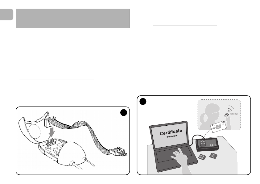
• The models with universal connector
are connected to
the O-Box unit by means of a special cable which must be
connected to the connector on the receiver (see fig. 8).
OTHER FUNCTIONS
8
9

Initially, the procedure consists in the installer entering, with
the aid of the programming unit “O-Box”, the required functions and the relative receiver “certificate” in the memory of
the transmitter. The transmitter, ready to use
the client.
Subsequently, when the transmitter is used, it will transmit the
command along with the “certificate” to the receiver (the first
twenty times only). The receiver, after recognising the “certificate” as its own, automatically memorises the identity code of
the transmitter that sent the certificate.
, is then sent to
12 – REMOTE REPLACEMENT OF A
TRANSMITTER USING “PRIORITY”
MODE
[with O-Box] – The identity code of a transmitter in the
NiceOne series is accompanied by a number
which enables the user to specify the transmitter’s priority
level on a receiver with respect to any other transmitters with
the same code.
This “priority” serves to replace, and thus disable, use of a
transmitter that has been lost or stolen, without the need to
return to the client’s system.
Use of priority mode requires knowledge of the code of the
lost transmitter and enables maintenance of the same code
and functions of the previous transmitter.
Therefore the lost transmitter can be disabled by simply
updating the priority level
next highest value.
On first use of the transmitter, the receiver memorises the new
priority level received and ignores any command sent by the
lost or stolen transmitter if subsequently used.
of the new transmitter with the
(from 0 to 3),
This function can be enabled (or disabled) on the receiver (fac-
tory setting ON) and, when active, the receiver does not
update the priority level sent by the transmitter.
13 – ENABLING (or disabling)
RECEPTION OF NON-ORIGINAL
“IDENTITY CODES”
[with O-Box / O-View] – The identity codes of transmitters
with “FloR” and “O-Code” encoding can be modified as
required, using the “O-Box” or “O-View” programming unit.
The receiver can normally recognise whether a code is original
(factory set) or modified.
When this function is enabled or disabled (factory setting ON)
the receiver has the option to accept (or not) the command of
a transmitter with a modified identity code.
14 – LOCKING (or unlocking)
THE MOBILE SECTION (Rolling code)
OF THE IDENTITY CODE
[with O-Box / O-View] – This function enables the user to
lock (or unlock) management on the receiver of the variable
section (rolling code) of an identity code sent by a transmitter.
When the lock function is active (factory setting OFF), the
receiver treats a “rolling code” as if it were a “fixed” code,
ignoring the variable section.
EN
15

16
EN
17 – ENABLING (or disabling)
COMMAND DELIVERY ON THE
“T4 BUS” NETWORK
[with O- View] – On systems in which connection is via the
“T4 Bus”, if more than one receiver is installed, and there is the
need for control at a distance greater than that normally covered by the transmitter and receiver, this function can be
enabled (on at least 2 receivers) to increase the receiver
reception range.
This enables the receiver that receives a command “via radio”
to re-transmit the command via the Bus cable
to the final
receiver (in which the sending transmitter identity code is
memorised), so that this can execute the command.
To enable or disable the option to receiver and/or send radio
codes on the “T4 Bus” in a receiver (factory setting OFF), the
receivers concerned must be duly programmed, using the OView programming unit.
18 – CREATING THE “FAMILY GROUPS”
OF TRANSMITTERS
[with O-Box] – Each code memorised on the receiver can
be associated with one or more “family groups”, from the 4
available.
The formation of groups and their activation or deactivation (fac-
tory setting OFF) is managed by means of the O-Box programming unit while use of the groups, for example in a set timeband, is managed by means of the O-View programming unit.
15 – ENABLING (or disabling)
THE “REPEATER” FUNCTION
(Function available only on models OXIT, OXITFM, OX2T,
OX2TFM, in combination with transmitters using O-Code
encoding).
[with O-Box] – If an automation is to be controlled at a distance greater than that normally covered by the transmitter
and receiver, a second receiver may be used (up to a maximum of five) serving to re-transmit, via radio
, the command to
the final receiver (in which the sending transmitter identity
code is memorised), so that this can execute the command.
To enable or disable this function (factory setting OFF) pro-
gramming must be performed both on the additional receivers
and transmitters.
16 – MANAGING RELEASE OF THE
TRANSMITTER KEYS
(Function available only on transmitters using O-Code
encoding)
[with O-Box / O-View] – Normally, after sending a command, on release of the key the manoeuvre is not stopped
immediately but proceeds for a very short pre-set interval.
If necessary, the manoeuvre can be interrupted at the exact
time of key release (required for example during minimal
adjustments) by enabling this function (factory setting OFF).

19 – PROTECTION OF PROGRAMMED
FUNCTION SETTINGS
[with O-Box / O-View] – This function enables the user to
protect all programmed functions on the receiver, also disabling functionality of the key and relative led. The function is
enabled by entering a password on the receiver, i.e. a maximum of 10 digits, as set by the installer.
When the function is enabled, before programming and maintenance of the receiver, the special password must be entered
on the programming unit to unlock the receiver.
DISPOSAL OF THE PRODUCT
This product constitutes an integral part of the automation system, therefore it must be disposed of along with it.
As in installation, also at the end of product lifetime, the disassembly and scrapping operations must be performed by qualified personnel.
This product is made up of different types of material, some of
which can be recycled while others must be disposed of. Seek
information on the recycling and disposal systems envisaged
by the local regulations in your area for this product category.
Caution! – some parts of the product may contain pollutant or
hazardous substances which, if disposed of into the environment, may cause serious damage to the environment or physical health.
As indicated by the symbol on the left,
disposal of this product in domestic
waste is strictly prohibited. Separate the
waste into categories for disposal,
according to the methods envisaged by
current legislation in your area, or return
the product to the retailer when purchasing a new version.
Caution! – Local legislation may envisage serious fines in the
event of abusive disposal of this product.
EN
17

18
EN
OXI OXIT OXIFM OXITFM
• Decoding “O-Code” / “FloR” / “TTS”; or “Flo”; or “Smilo”
• Maximum absorption 30 mA
• Reception frequency 433.92 MHz 868.46 MHz
• Transmission frequency ––– 433.92 MHz ––– 868.46 MHz
• Sensitivity Above 0.5 µV Above 0.8 µV
• Operating temperature –20° C ÷ +55° C
• Outputs 4 (on “SM” connector)
• Dimensions and weight L. 50; H. 45; P. 19 mm; weight 20
• Radiated power ––– approx. 1 mW E.R.P. ––– approx. 1 mW E.R.P.
• Input impedance 52 ohm
OX2 OX2T OX2FM OX2TFM
• Decoding “O-Code” / “FloR” / “TTS”; or “Flo”; or “Smilo”
•
Power supply
Without electric jumper = 24 V standard. Limits from 18 to 28 V direct or alternating
With electric jumper = 12 V standard. Limits from 10 to 18 V direct or alternating
• Absorption on standby 10 mA at 24 Vac
• Absorption with 2 relays activ 80 mA at 24 Vac.
• Reception frequency 433.92 MHz 868.46 MHz
• Transmission frequency ––– 433.92 MHz ––– 868.46 MHz
• Sensitivity Above 0.5 µV Above 0.8 µV
• N° relays 2
• Relay contact Normally open max 0,5 A and 50 V
• Operating temperature –20° C ÷ +55° C
• Protection rating IP 30
• Dimensions and weight 58 x 86; H. 22 mm; weight 55 g
• Radiated power ––– approx. 1 mW E.R.P. ––– approx. 1 mW E.R.P.
PRODUCT TECHNICAL SPECIFICATIONS

GENERAL NOTES
As well as the functions and settings described in this
manual, the receiver offers many other features to
enhance performance, safety and ease of use.
All these settings require use of the O-Box (or in some
cases O-View) programming unit.
For further information on the settings available, refer to
the general system manual “NiceOpera System Book”, or
the O-Box/ O-View programming unit manual.
• Notes on Product Technical specifications
– The range of the transmitters and reception capacity of the
receivers is strongly influenced by other devices (for example: alarms, radio headphones etc.) operating in the zone at
the same frequency. In these cases, Nice cannot guarantee
the effective capacity of its devices.
– All technical specifications stated in this section refer to an
ambient temperature of 20°C (± 5°C).
– Nice reserves the right to apply modifications to the product
at any time when deemed necessary, while maintaining the
same functionalities and intended use.
EN
19

20
EN
Table A
SIGNALS EMITTED BY THE
RECEIVER LED
–– Long flashes / GREEN ––
On start-up:
1 ✺ = Code in use: “Flo”
2 ✺ = Code in use: “O-Code”/“FloR”
3 ✺ = Code in use: “Smilo”
5 ✺ = No remote control memorised
During operation:
1 ✺ = Indicates that the code received is not stored in the
memory
1 ✺ = During programming, indicates that the code is
already stored in the memory
3 ✺ = Saving code in memory
5 ✺ = Memory deleted
6 ✺ = During programming, indicates that the code is not
authorised for memorisation
8 ✺ = Memory full
––––––––––––––––––––––––––––––––––––––––––––––––––
–– Short flashes / GREEN ––
1 ✺ = “Certificate” not valid for memorisation
2 ✺ = Code cannot be memorised as is transmitting
“certificate”
3 ✺ = During programming, indicates that the code has
been re-synchronised
4 ✺ = Output in “Mode II” not managed on control unit
5 ✺ = During deletion procedure, indicates that the code
has been deleted
5 ✺ = “Certificate” with higher priority that the admissible
value
6 ✺ = Code synchronisation failure
6 ✺ = Code cannot be memorised due to “incorrect key”
––––––––––––––––––––––––––––––––––––––––––––––––––
–– Long flashes / RED ––
1 ✺ = Non-original code block
2 ✺ = Code with lower priority than the authorised value
––––––––––––––––––––––––––––––––––––––––––––––––––
–– Short flashes / RED ––
1 ✺ = “In vicinity” programming mode block
1 ✺ = Memorisation by means of “certificate” block
2 ✺ = Memory block (PIN entry)
––––––––––––––––––––––––––––––––––––––––––––––––––
–– Long flashes / ORANGE ––
1 ✺ = Indicates that the code is in the memory but
outside the group currently enabled
––––––––––––––––––––––––––––––––––––––––––––––––––
–– Short flashes / ORANGE ––
2 ✺ = Indicates activation of block programming
(on start-up)

EC DECLARATION OF CONFORMITY
Note –This Declaration of Conformity contains the individual declarations of conformity for the specified products; it was updated on the issue
date of this manual and the text herein has been drawn up for editorial purposes. A copy of the original declaration for each product can be
requested from Nice S.p.a. (TV) I.
Number: 256/OXI Revision: 3 Language: EN
The undersigned Luigi Paro, as Managing Director, declares on his own responsibility that the product:
Manufacturer’s name : Nice S.p.a.
Address: Via Pezza Alta 13, Z.I. Rustignè, 31046 Oderzo (TV) Italy
Type: Receiver and receiver-transmitter for remote control of automations for doors, gates, shutters,
Models: OXI, OXIT, OXIFM, OXITFM
Accessories:
conform with the requirements of the EC directive:
• 1999/5/EC; DIRECTIVE 1999/5/EC OF THE EUROPEAN PARLIAMENT AND COUNCIL of 9 March 1999 regarding
radio equipment and telecommunications terminal equipment and the mutual recognition of their conformity
According to the following harmonised standards
Health protection (art.3(1)(a)): EN 50371:2002
Electrical safety (art.3(1)(a)): EN 60950-1:2006; +A11:2009
Electromagnetic compatibility (art.3(1)(b)): EN 301 489-1V1.6.1:2006; EN 301 489-3V1.4.1:2002
Radio range (art.3(2)): EN 300220-2V2.3.1:2010
Oderzo, 12 August 2011 Luigi Paro (Managing Director)
awnings, rolling shutters and similar applications.
EN
21

22
EN
EC DECLARATION OF CONFORMITY
Note –This Declaration of Conformity contains the individual declarations of conformity for the specified products; it was updated on the issue
date of this manual and the text herein has been drawn up for editorial purposes. A copy of the original declaration for each product can be
requested from Nice S.p.a. (TV) I.
Number: 259/OX2 Revision: 5 Language: EN
The undersigned Luigi Paro, as Managing Director, declares on his own responsibility that the product:
Manufacturer’s name : Nice S.p.a.
Address: Via Pezza Alta 13, Z.I. Rustignè, 31046 Oderzo (TV) Italy
Type: Receiver and receiver-transmitter for remote control of automations for doors, gates, shutters,
awnings, rolling shutters and similar applications.
Models: OX2, OX2T, OX2FM, OX2TFM
Accessories:
conform with the requirements of the EC directive:
• 1999/5/EC; DIRECTIVE 1999/5/EC OF THE EUROPEAN PARLIAMENT AND COUNCIL of 9 March 1999 regarding
radio equipment and telecommunications terminal equipment and the mutual recognition of their conformity
According to the following harmonised standards
Health protection (art.3(1)(a)): EN 50371:2002
Electrical safety (art.3(1)(a)): EN 60950-1:2006; +A11:2009
Electromagnetic compatibility (art.3(1)(b)): EN 301 489-1V1.6.1:2006; EN 301 489-3V1.4.1:2002
Radio range (art.3(2)): EN 300220-2V2.3.1:2010
Oderzo, 12 August 2011 Luigi Paro (Managing Director)

ITALIANO
Istruzioni originali
1 – DESCRIZIONE DEL PRODOTTO E
DESTINAZIONE D’USO
Il presente ricevitore fa parte della serie “NiceOne” di Nice spa.
I ricevitori di questa serie sono destinati all’uso sulle Centrali di
comando presenti negli impianti di automatizzazione di cancelli, portoni da garage e alzabarriere stradali. Ogni altro uso è
da considerarsi improprio e vietato! Il costruttore non
risponde dei danni risultanti da un uso improprio del prodotto, diverso da quanto previsto nel presente manuale.
Sono disponibili vari modelli, con le caratteristiche essenziali
riportate nella tabella in basso.
1.1 – Il sistema “NiceOpera”
I ricevitori della serie NiceOne fanno parte del sistema
“NiceOpera”. Questo sistema è stato progettato da Nice per
semplificare le fasi di programmazione, di uso e di manutenzione dei dispositivi usati negli impianti di automatizzazione.
Il sistema è formato da vari dispositivi, software e hardware,
capaci di scambiarsi fra loro dati e informazioni via radio, attraverso un sistema di codifica chiamato “O-Code” o un collegamento ‘fisico’, tramite cavo.
I principali dispositivi che formano il sistema NiceOpera sono:
– trasmettitori NiceOne;
– ricevitori NiceOne;
– unità di programmazione O-Box;
– centrali e motoriduttori con “Bus T4”;
– programmatore O-View per dispositivi con “Bus T4”.
IMPORTANTE – Per approfondire in dettaglio tutte le funzionalità del sistema NiceOpera e l’interdipendenza operativa che lega i vari dispositivi del sistema, consultare il
manuale generale “NiceOpera System Book”, disponibile
anche nel sito internet www.niceforyou.com
IT
Mod. Frequenza Funzione Connessione
OXI 433.92 MHz Ricevitore ad innesto
OXIFM 868.46 MHz Ricevitore ad innesto
OXIT 433.92 MHz Ricetrasmettitore ad innesto
OXITFM 868.46 MHz Ricetrasmettitore ad innesto
OX2 433.92 MHz Ricevitore con cavo a 6 fili
OX2FM 868.46 MHz Ricevitore con cavo a 6 fili
OX2T 433.92 MHz Ricetrasmettitore con cavo a 6 fili
OX2TFM 868.46 MHz Ricetrasmettitore con cavo a 6 fili
Note alla tabella:
– Le frequenze 433.92 MHz
e 868.46 MHz non sono
compatibili tra loro.
– La lettera “T” nella sigla indica un ricevitore con un trasmettitore incorporato.
1

2
IT
2 – CARATTERISTICHE FUNZIONALI DEL
PRODOTTO
• Per tutti i modelli
– Il ricevitore gestisce la codifica radio chiamata “O-Code”,
con codice variabile (rolling-code), che permette di sfruttare
tutte le nuove funzioni del Sistema NiceOpera.
Il ricevitore è compatibile anche con le codifiche “FloR”,
“TTS”, “Smilo” e “Flo”. In questo caso però, non sarà pos-
sibile sfruttare alcune funzionalità esclusive del Sistema
NiceOpera, descritte in questo manuale.
– Il ricevitore dispone di una memoria con 1024 spazi in cui
memorizzare i trasmettitori. Se questo viene memorizzato in
“Modo I”, tutti i suoi tasti
occuperanno 1 spazio di memoria;
se invece viene memorizzato in “Modo II”, ogni suo tasto
memorizzato occuperà 1 spazio di memoria (per le modalità
di memorizzazione, vedere avanti nel manuale).
– Ogni ricevitore possiede un proprio numero di identificazio
—
ne chiamato “Certificato”. Questo numero permette di
accedere a molte operazioni come, ad esempio: la memorizzazione di nuovi trasmettitori senza la necessità di intervenire direttamente sul ricevitore e l’uso dell’unità O-View
sfruttando il collegamento con “Bus T4”.
Il tagliando sigillato contenuto nella confezione del prodotto
riporta stampato al suo interno il numero di certificato
appartenente al presente ricevitore. Attenzione! – questo
tagliando deve essere custodito in un posto sicuro perché
consente l’accesso ai dati contenuti nel ricevitore, a meno
che, non vengano inserite ulteriori protezioni come l’uso di
Password di sicurezza.
• Per i modelli con innesto “SM”
– Questi modelli possono essere usati esclusivamente con le
Centrali di comando dotate di connettore ad innesto di tipo
“SM” (fig. 1). Nota — per identificare le Centrali idonee, con-
sultare il catalogo prodotti di Nice.
– Questi modelli riconoscono automaticamente le caratteristi-
che della Centrale nella quale vengono inseriti e il ricevitore
si auto-imposta nel modo seguente.
• Se la Centrale gestisce il “Bus T4”
, il ricevitore rende
disponibili fino a 15 comandi diversi.
• Se la Centrale non gestisce il “Bus T4”
, il ricevitore ren-
de disponibili fino a 4 canali comandi diversi.
Attenzione! – In ambedue i casi, il numero e la varietà dei
comandi a disposizione dipendono dal tipo e dal modello di
Centrale che si utilizza. La “Tabella dei comandi” di ciascuna
Centrale è riportata nel manuale istruzioni della Centrale
stessa.
• Per i modelli con connessione universale
– Questi modelli funzionano con 2 relè a contatto pulito; quin-
di possono essere usati con qualsiasi tipo di Centrale.
• Per i modelli con la “T” nella sigla
– Questi modelli sono dotati della funzione “Repeater” (vedere
avanti nel manuale) che consente di aumentare il raggio di
trasmissione dei trasmettitori. Inoltre, consentono di poter
comunicare in modo “wireless” con l’unità di programmazione O-Box.
3 – INSTALLAZIONE DEL PRODOTTO
• Per i modelli con innesto “SM”
Questi modelli si collegano alla Centrale di comando innestando il loro connettore in quello specifico presente sulla Centrale
(fig. 1). Attenzione! – Prima di innestare o di rimuovere il
ricevitore, togliere l’alimentazione elettrica alla Centrale.
Inoltre, occorre installare anche l’antenna in dotazione, collegandola agli appositi morsetti presenti sulla Centrale.
• Per i modelli con connessione universale
––– Selezione dell’alimentazione –––
Questi modelli si collegano alla Centrale di comando tramite
un cavo con 6 fili interni. Prima di collegare il cavo, selezionare
il tipo di alimentazione desiderata, lasciando inserito o togliendo il ponticello elettrico (fig. 2—a) nel modo seguente:
1
– Ponticello NON inserito
(limiti di tensione: 18 ÷ 28 V)
– Ponticello INSERITO
(limiti di tensione: 10 ÷ 18 V)
2
a
= 24 V ac/dc
= 12 V ac/dc
IT
3

4
IT
––– Collegamenti elettrici –––
Collegare negli appositi morsetti presenti sulla Centrale i 6 fili
elettrici del cavo del ricevitore nel modo seguente (fig. 3):
• Rosso e Nero = ALIMENTAZIONE
(rosso = Positivo, nero = Negativo. In corrente alternata,
questo è indifferente).
• Bianco e Bianco = USCITA 1° RELÈ
(contatto pulito di un relè normalmente aperto).
• Viola e Viola = USCITA 2° RELÈ
(contatto pulito di un relè normalmente aperto).
––– Come ottenere contatti di tipo “
NC” –––
Le uscite sono comandate da 2 relè con contatto di tipo “NA”
(normalmente aperto). Se si vuole ottenere un contatto di tipo
“NC” (normalmente chiuso), procedere nel modo seguente:
01. Togliere l’alimentazione elettrica al ricevitore.
02. Aprire il box del ricevitore sollevando prima la parte pic-
cola del coperchio (fig. 4—a) e successivamente quella
grande con il tasto (fig. 4—b).
03. Estrarre con cura la scheda e girarla: il lato con le salda-
ture deve essere rivolto verso l’osservatore.
04. Sul lato con le saldature, effettuare le seguenti operazioni
(fig. 5):
– Tagliare il tratto di traccia nel punto “X”.
– Unire con una goccia di stagno le piazzole nei punti “Y”.
Nota – queste modifiche possono essere fatte su un relè
o sutti e due, secondo le vostre necessità.
3
Rosso
Nero
Bianco
Bianco
Viola
Viola
a

4
5
IT
a
b
5

6
IT
• Per tutti i modelli:
installazione di un’antenna esterna
Se l’antenna in dotazione viene a trovarsi in posizione sfavorevole e il segnale radio risulta debole, per migliorare la ricezione
è consigliabile sostituire questa installando un’antenna esterna (mod. ABF o ABFKIT). La nuova antenna deve essere posizionata più in alto possibile e al di sopra di eventuali strutture
metalliche o di cemento armato presenti nella zona.
– Collegamento alla Centrale
: usare un cavo coassiale con
impedenza di 50 ohm (ad esempio, il cavo RG58 a bassa
perdita). Attenzione! – Per ridurre la dispersione del segnale,
usare un cavo più corto possibile (non deve superare i 10 m).
– Collegamento al ricevitore
(solo per i modelli con con-
nessione universale): aprire il ricevitore sollevando la parte
piccola del coperchio (fig. 4-a) e scollegare l’antenna in
dotazione; quindi, collegare il cavo della nuova antenna al
morsetto 1 e 2 in questo modo (fig. 3—a): morsetto 1 = cal-
za; morsetto 2 = anima.
Avvertenze alla programmazione
Le programmazioni presenti in questo capitolo (esclusa la
procedura 6) richiedono l’uso del tasto e del Led sul ricevitore (fig. 6). Per indicare lo stato delle attività in corso, il
Led emette un determinato numero di lampeggi con una
durata specifica e un determinato colore di luce (verde,
rosso o arancione). Per conoscere il significato di queste
segnalazioni consultare la Tabella A, presente alla fine
del manuale.
PROGRAMMAZIONE DELLE
FUNZIONI PRINCIPALI
6
Led Tasto
Led Tasto
Loading…
Содержание
- Программирование пультов Nice Era INTI — инструкции
- Режим 1. Программирование пульта в целом.
- Режим 2. Программирование отдельных кнопок пульта.
- Запись пульта в «Режиме 2 расширенный»
- Запись пульта с использованием «Сертификата приемника»
- Запись через «Разрешающий код»
- Индикация ошибок:
- Инструкция NICE OX2
- Управление выходами Nice OX2
- ДмитрийSPb
- kart4
- ДмитрийSPb
- Boroda365
- У нас вы найдёте инструкции для всех видов автоматики NICE (Италия)
- Инструкции для всех видов автоматики NICE
- Автоматика для распашных ворот NICE
- Автоматика для откатных ворот NICE
- Автоматика для секционных ворот NICE
- Шлагбаумы NICE
- Внешние блоки управления NICE
- Встроенные блоки управления NICE
- Пульты дистанционного управления NICE
- Радиоприемники NICE
- Аксессуары для автоматики NICE
- Система Opera
- Как воспользоваться мануалами с нашего сайта
Программирование пультов Nice Era INTI — инструкции
В зависимости от типа приемника в блок управления посредством пульта можно передать определенное количество команд. Приемники серии OXI имеют возможность передачи до 15 команд. Универсальные приемники OX имеют 2 выхода.
Присвоение кнопкам Nice Era Inti определенных команд может быть выполнено в двух режимах:
Режим 1. Программирование пульта в целом.
Кнопкам пульта присваиваются команды, предварительно установленные на блоке управления (серия OXI) или на выходе приемника (OX)
- Нажать и удерживать кнопку приемника, пока на нем не загорится индикатор. Отпустить кнопку.
- В течение 10 секунд нажать и удерживать любую кнопку пульта, до тех пор пока индикатор на приемнике не мигнет 3 раза. Пульт прописан.
- В течение 10 секунд можно прописать в приемник следующий пульт.
Режим 2. Программирование отдельных кнопок пульта.
Предварительно необходимо изучить «таблицу возможных команд» блока управления и выбрать команды для присвоения кнопкам пульта.
- На приемнике нажать кнопку такое количество раз, которое соответствует выбранной команде. Индикатор приемника мигнет столько же раз, подтвердив выбор функции;
- В течение 10 секунд нажать соответствующую кнопку пульта и удерживать до тех пор, пока индикатор приемника не мигнет 3 раза. Кнопка запрограммирована.
- После этого в течение 10 секунд можно программировать другую кнопку пульта, начиная с шага 1)
Запись пульта в «Режиме 2 расширенный»
В расширенном режиме запись аналогична «Режиму 2». Расширенный режим работает в устройствах NiceOpera с поддержкой O-Code и позволяет выбрать из 15 команд, предустановленных в блоке управления. Режим доступен для приемников серии OXI (разъем SM)
Запись пульта с использованием «Сертификата приемника»
Установщик с помощью программатора O-Box записывает в память Nice Era Inti команды для кнопок и сертификат приемника. С этого момента пульт становится готовым для использования. Приемник распознает свой сертификат и прописывает новый пульт в память.
Запись через «Разрешающий код»
Позволяет скопировать информацию с одного пульта на другой. Процедура, используемая для передачи «разрешающего кода» со СТАРОГО пульта на НОВЫЙ следующая:
- Держать пульты друг напротив друга так, чтобы они соприкасались
- Нажмать любую кнопку на НОВОМ пульте и держать её нажатой, до тех пор пока не загорится индикатор на СТАРОМ пульте.
- Отпустить кнопку. Индикатор на СТАРОМ пульте начнет мигать
- Нажаать любую кнопку на СТАРОМ пульте и держать её нажатой, до тех пор пока не загорится индикатор на НОВОМ пульте.
- Отпустить кнопку — индикатор погаснет, обозначая конец программирования и успешную запись «разрешающего кода» на новый пульт.
Индикация ошибок:
- 4 вспышки: запись «инициирующего кода» запрещена;
- 6 вспышек: запись «инициирующего кода» между передатчиками с разным количеством каналов отключена;
- 10 вспышек: ошибка связи между пультами;
- 15 вспышек: передача не удалась из-за превышения временного лимита
Первые 20 нажатий новый пульт будет передавать приемнику одновременно с командой «разрешающий код». Когда приемник распознает «разрешающий код», он автоматически запомнит идентификатор пульта, который его отослал
Источник
Инструкция NICE OX2
Внешний двухканальный приемник NICE OX2 является одним из приемников серии продуктов NiceOne, существуют различные модификации работающие на разных частотах (433 и 868 Мгц) и обладающие различнымии функциями.
Приемник NICE OX2 возможно подключить к автоматики для ворот или шлагбаумам разных производителей, что дает возможность управлять ими пультами дистанционного управления NICE.
Приемник NICE OXI поддерживает возможность работаты с пультами NICE разных серий. Первый записанный пульт определяет возможность приемника запоминать последующие. Возможно записывать пульты серии FLO, FLOR, O-CODE, TTS или SMILO. При отсутвии рабочего, ранее записанного в память приемника пульта, определить кодировку которую поддерживает данный приемник, можно по количеству вспышек зеленого светодиода расположенного на приемнике. Для этого необходимо выключить и включить питание блока управления, после включения питания светодиод зеленого цвета моргнет 1, 2, 3 или 5 раз. Что соответсвует:
1 вспышка — кодировка пультов серии FLO (фиксированный код)
2 вспышки — кодировки пультов серии FLOR, O-CODE или TTS (динамический код)
3 вспышки — кодировка пультов серии SMILO
Приемник имеет несколько режимов программирования в том числе и дистанционный. Для дистанционного программирования необходим рабочий пульт ранее записанный в приемник NICE OXI в 1 или 2 режимах, дополнительный пульт будет записан дистанционно в таком же режиме, и обладать такими же функциями как и ранее записанный. Процедура дистанционного программирования дополнительных пультов производиться в радиусе действия приемника (10-20 метров от блока управления).
Порядок действий при дистанционном программировании дополнительного пульта:
1. Нажать и удерживать нажатой в течении более 5 секунд любую кнопку НОВОГО пульта.
2. Три раза по 1 секунде нажать и отпустить на кнопку РАБОЧЕГО пульта открывающую ворота или шлагбаум.
3. Один раз на 1 секунду нажать на кнопку НОВОГО пульта.
4. Если необходимо записать насколько дополнительных пультов, повторите 1-3 пункты для записи последующих пультов.
С полной инструкцией NICE OX2 можно ознакомиться или скачать по ссылке ниже.
Источник
Управление выходами Nice OX2
Всем добрый день! Помогите пожалуйста разобраться с выносным приёмником nice ox2. У него два выхода. Как запрограмировать пульт, что бы одна кнопка управляла выходом 1, а другая — выходом 2. Как ни пытался — на обоих кнопках выход 1. По инструкции ни чего не понятно. Спасибо всем, кто откликнется.
ДмитрийSPb
Эксперт
kart4
Новичок
В инструкции:
01. Найти в инструкции блока «Таблицу возможных команд». Выбрать команду,
которую необходимо закрепить за кнопкой приемника и только потом присвоить номер,
который соответствует команде.
Вопрос: что значит и каким образом я должен присвоить номер, который соответствует команде?
В инструкции:
02. (На приемнике) Нажать кнопку столько раз, сколько вспышек светодиода (световых
сигналов) замечено ранее.
Вопрос: что значит «замечено ранее»?
ДмитрийSPb
Эксперт
Boroda365
Эксперт
«команде» это применимо к OXI, если касательно приемника OX2, то количество вспышек будет соответствовать выбранному выходу/реле (одна вспышка — 1-й выход, две вспышки — 2-й выход).
Вы процитировали выдержку из инструкции касающуюся программирования приемника OXI, а у Вас OX2.
Инструкция написана для приемников одной серии ONE, в этой серии несколько разновидностей приемников. Основные приемники это OXI для SM соединения/разъема (встраиваемый в блок управления) и OX2 с возможностью подключения с помощью проводов и имеющие два выхода/реле (возможность подключить к двум блокам управления). Я обвел на что необходимо обратить внимание читая инструкцию и она станет понятней в отношении с OX2.
Источник
У нас вы найдёте инструкции для всех видов автоматики NICE (Италия)
Для корректной установки и грамотно использования любого оборудования необходимо под рукой иметь инструкцию. Не является исключением и автоматика для шлагбаумов и ворот, выпускаемая итальянской компанией под брендом NICE.
Инструкции для всех видов автоматики NICE
Самая обширная коллекция инструкций для автоматики NICE представлена на нашем сайте. Есть необходимая документация на автоматику для откатных, распашных и секционных ворот, для шлагбаумов и другого оборудования. Все документы представлены на русском языке в формате pdf, что очень удобно для наших пользователей.
В мануалах есть:
- описание устройств;
- подробные инструкции по установке приводов;
- по установке блоков управления;
- по техническому обслуживанию;
- предупреждения о технике безопасности.
С помощью наших руководств вы узнаете обо всех функциях вышеуказанного оборудования, в том числе и о тех, о которых даже и не подозревали.
Автоматика для распашных ворот NICE
Серия HYPPO
Серия METRO
Серия Moby 4000
Серия Moby 5000
Серия POP
Серия TOONA
Серия WALKY
Серия WINGO
Серия ТОО
Автоматика для откатных ворот NICE
ROAD (RD 400)
ROBO
ROBO 300
RO 500
ROBUS 350
ROBUS (RB 600 и RB 1000)
RUN
THOR
THORKIT
Автоматика для секционных ворот NICE
CLIMBER
SHEL50KIT / SHEL75KIT
SOON
SPIDER
SPIDO
SPIN (10 и 11)
SPINBUS (21, 22 и 6041)
SUMO
TOM S
Шлагбаумы NICE
Шлагбаум SIGNO
Шлагбаум S-BAR
Шлагбаум M/L-BAR
Шлагбаум X-BAR
Шлагбаум WIL
Внешние блоки управления NICE
Блок управления A0
Блок управления A400
Блок управления A500
Блок управления A6 / A6F / A700F
Блок управления A60
Блок управления A824
Блок управления A924
Блок управления MC824H
Блок управления MC424
Встроенные блоки управления NICE
Встроенный блок для ROBO
Встроенный блок для ROBO 1024
Встроенный блок POA1
Встроенный блок SIA20/A (Модификация для SIGNO)
Встроенный блок для SPIDER
Встроенный блок WA20 для WIL
Пульты дистанционного управления NICE
Пульт FLOR
Пульт INTI
Пульт NICEONE
Пульт NICEONE OX / OXI
Пульт NICEWAY
Радиоприемники NICE
SMILO
TAG TT1N
TAG TT2N
TAG TT1L
TAG TT2L
С постоянным кодом FLO
С динамическим кодом FLOR
С динамическим кодом SMXI
С динамическим кодом TTX4
Аксессуары для автоматики NICE
Аккумуляторные батареи PS 424
Аккумуляторные батареи PS 224
Комплект для разблокировки секционных ворот MU
Обогревательные элементы TW1
Радиопереключатели MOT
Радиопереключатели SELD
Сигнальные лампы Wallyght
Системы управления доступом MOON
Фотоэлементы FE/FI/FEB/BF
Фотоэлементы FT 210
Фотоэлементы FT 210B (BlueBus)
Фотоэлементы MOF (BlueBus)
Система Opera
Как воспользоваться мануалами с нашего сайта
Вы можете сказать, что документация всегда поставляется вместе с изделием. Но она может быть не на вашем родном языке, напечатана мелким шрифтом или затеряться. Мы позаботились, чтобы наши пользователи не сталкивались с такими проблемами и скачивали инструкции совершенно бесплатно. Без паролей и регистрации. Достаточно выбрать на этой странице нужную модель, и после одного клика раскроется документ с подробными чертежами, доступными объяснениями и оптимальным для чтения шрифтом.
К примеру, инструкции для шлагбаумов NICE находятся под заглавием «Шлагбаумы». Выбираете подходящий вариант и пользуетесь инструкцией по установке: её можно изучать online, сохранить у себя на диске или распечатать.
Описания настолько простые, подробные и понятные, что даже неопытные пользователи редко совершают ошибки во время монтажных работ и на этапе подключения. А при правильной установке и эксплуатации автоматика NICE будет служить вам долго, надёжно, предоставит максимальную безопасность и свободу передвижения без особых усилий по обслуживанию.
Источник
-
#5
Если не ошибаюсь, то количество нажатий и вспышек соответствует выбранной команде
«команде» это применимо к OXI, если касательно приемника OX2, то количество вспышек будет соответствовать выбранному выходу/реле (одна вспышка — 1-й выход, две вспышки — 2-й выход).
Вы процитировали выдержку из инструкции касающуюся программирования приемника OXI, а у Вас OX2.
Инструкция написана для приемников одной серии ONE, в этой серии несколько разновидностей приемников. Основные приемники это OXI для SM соединения/разъема (встраиваемый в блок управления) и OX2 с возможностью подключения с помощью проводов и имеющие два выхода/реле (возможность подключить к двум блокам управления). Я обвел на что необходимо обратить внимание читая инструкцию и она станет понятней в отношении с OX2.
-
Screenshot_20211016_153606.jpg
794 KB
· Просмотры: 86
Последнее редактирование: