
MSI
Loading…
B
- B150A
- B150A GAMING PRO3
- B150A TOMAHAWK
- B150 Gaming M33
- B150I Gaming Pro AC2
- B150M ECO
- B150M Grenade3
- B150M MORTAR5
- B150M Mortar Arctic2
- B150M NIGHT ELF
- B150M PRO-DH
- B150M PRO-VDH2
- B150M PRO-VHL
- B150 PC MATE3
- B150 TOMAHAWK
- B250 gaming M32
- B250 Gaming Pro carbon
- B250I GAMING PRO AC2
- B250M BAZOOKA2
- B250M BAZOOKA OPT BOOST
- B250M BAZOOKA PLUS
- B250M MORTAR
- B250M PRO-VD2
- B250M PRO-VDH2
- B250M PRO-VH
- B250 PC MATE
- B320M gaming pro
- B350
- B350M Mortar2
- B350M PRO-VDH
- B350M Pro-VD Plus2
- B350M PRO-VH PLUS
- B350 PC MATE
- B350 TOMAHAWK
- B360-A Pro2
- B360-F Pro2
- B360 Gaming Arctic2
- B360 Gaming Plus3
- B360 Gaming Pro carbon2
- B360I Gaming Pro AC2
- B360M BAZOOKA3
- B360M Gaming Plus2
- B360M Mortar2
- B360M MORTAR ILYA MUROMETS
- B360M Mortar titanium2
- B360M Pro-VD2
- B360M Pro-VDH2
- B360M Pro-VH
- B365M Mortar
- B365M PRO-VDH2
- B365M Pro-VH2
- B450
- B450-A Pro2
- B450-A Pro Max3
- B450 Gaming Plus2
- B450 Gaming Plus Max3
- B450 Gaming Pro carbon AC2
- B450 Gaming Pro carbon Max WIFI3
- B450I Gaming Plus AC3
- B450I Gaming Plus Max WIFI3
- B450M
- B450M-A Pro Max2
- B450M Bazooka V22
- B450M GAMING PLUS
- B450M Mortar Max3
- B450M PRO-M2
- B450M Pro-M2 Max2
- B450M Pro-VDH Max2
- B450M PRO-VDH PLUS
- B450M Pro-VDH V22
- B450 TOMAHAWK2
- B450 TOMAHAWK MAX2
- B450 Tomahawk Max II3
- B460I Gaming Edge WIFI
- B460M-A Pro
- B460M Bazooka
- B460M Mortar
- B460M Mortar WIFI
- B460M Pro2
- B460M Pro-VDH2
- B460M Pro-VDH WIFI3
- B460 Tomahawk
- B460 Torpedo
- B4MW-047
- B4MW-048
- B550-A Pro2
- B550 Gaming carbon WIFI
- B550 Gaming Edge WIFI
- B550 Gaming Plus
- B550I Gaming Edge WIFI
- B550M Bazooka
- B550M Mortar
- B550M Mortar WIFI
- B550M PRO2
- B550M Pro-DASH3
- B550M Pro-VDH3
- B550M Pro-VDH WIFI2
- B550 Tomahawk
- B550 Torpedo
- B75A-E33
Loading…
Loading…
Nothing found
B365M Pro-VH
Service Manual
1 pgs1.52 Mb1
User Manual
152 pgs9.5 Mb0
Table of contents
Loading…
…
MSI User Manual
Download
Specifications and Main Features
Frequently Asked Questions
User Manual


Loading…
+ 122 hidden pages
You need points to download manuals.
1 point = 1 manual.
You can buy points or you can get point for every manual you upload.
Buy points
Upload your manuals

1
< 1> Contents
Contents
Safety Information ………………………………………………………………………………. 2
Specifications ………………………………………………………………………………………3
Rear I/O Panel ……………………………………………………………………………………..6
B365M PRO-VH ………………………………………………………………………………………6
B365M PRO-VD ………………………………………………………………………………………6
B365M WIND ………………………………………………………………………………………….6
LAN Port LED Status Table ………………………………………………………………………7
Overview of Components ……………………………………………………………………..7
CPU Socket ……………………………………………………………………………………………8
DIMM Slots …………………………………………………………………………………………….9
PCI_E1~3: PCIe Expansion Slots ………………………………………………………………9
JFP1, JFP2: Front Panel Connectors ………………………………………………………10
SATA1~6: SATA 6Gb/s Connectors…………………………………………………………..10
M2_1: M.2 Slot (Key M) (B365M PRO-VD, B365M PRO-VH) ………………………..11
ATX_PWR1, CPU_PWR1: Power Connectors…………………………………………….11
JUSB1, JUSB2: USB 2.0 Connectors ……………………………………………………….12
JUSB3: USB 3.1 Gen1 Connector ……………………………………………………………12
JAUD1: Front Audio Connector ………………………………………………………………. 13
JCOM1: Serial Port Connector ……………………………………………………………….13
JTPM1: TPM Module Connector ……………………………………………………………..13
EZ Debug LED ………………………………………………………………………………………13
CPU_FAN1, SYS_FAN1: Fan Connectors ………………………………………………….14
JCI1: Chassis Intrusion Connector ………………………………………………………….15
JBAT1: Clear CMOS (Reset BIOS) Jumper ……………………………………………….15
BIOS Setup ……………………………………………………………………………………….. 16
Entering BIOS Setup ……………………………………………………………………………..16
Resetting BIOS ……………………………………………………………………………………..17
Updating BIOS ………………………………………………………………………………………17
Installing OS, Drivers & Utilities ………………………………………………………….18
Installing Windows® 10 ………………………………………………………………………….18
Installing Drivers ………………………………………………………………………………….18
Installing Utilities ………………………………………………………………………………….18
Thank you for purchasing the MSI® B365M PRO-VD/ B365M
PRO-VH/ B365M WIND motherboard. This User Guide gives
information about board layout, component overview, BIOS
setup and software installation.

2Safety Information
Safety Information
yThe components included in this package are prone to damage from electrostatic
discharge (ESD). Please adhere to the following instructions to ensure successful
computer assembly.
yEnsure that all components are securely connected. Loose connections may cause
the computer to not recognize a component or fail to start.
yHold the motherboard by the edges to avoid touching sensitive components.
yIt is recommended to wear an electrostatic discharge (ESD) wrist strap when
handling the motherboard to prevent electrostatic damage. If an ESD wrist strap is
not available, discharge yourself of static electricity by touching another metal object
before handling the motherboard.
yStore the motherboard in an electrostatic shielding container or on an anti-static
pad whenever the motherboard is not installed.
yBefore turning on the computer, ensure that there are no loose screws or metal
components on the motherboard or anywhere within the computer case.
yDo not boot the computer before installation is completed. This could cause
permanent damage to the components as well as injury to the user.
yIf you need help during any installation step, please consult a certified computer
technician.
yAlways turn off the power supply and unplug the power cord from the power outlet
before installing or removing any computer component.
yKeep this user guide for future reference.
yKeep this motherboard away from humidity.
yMake sure that your electrical outlet provides the same voltage as is indicated on
the PSU, before connecting the PSU to the electrical outlet.
yPlace the power cord such a way that people can not step on it. Do not place
anything over the power cord.
yAll cautions and warnings on the motherboard should be noted.
yIf any of the following situations arises, get the motherboard checked by service
personnel:
Liquid has penetrated into the computer.
The motherboard has been exposed to moisture.
The motherboard does not work well or you can not get it work according to
user guide.
The motherboard has been dropped and damaged.
The motherboard has obvious sign of breakage.
yDo not leave this motherboard in an environment above 60C (140F), it may
damage the motherboard.

3
Safety Information Specifications
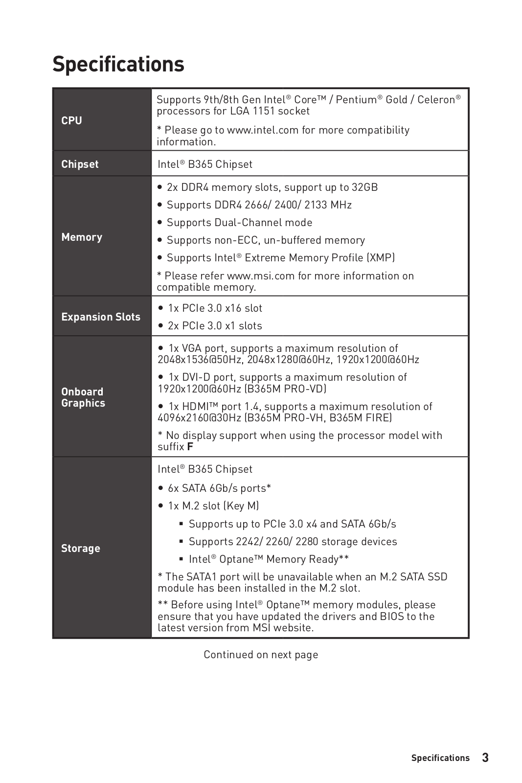
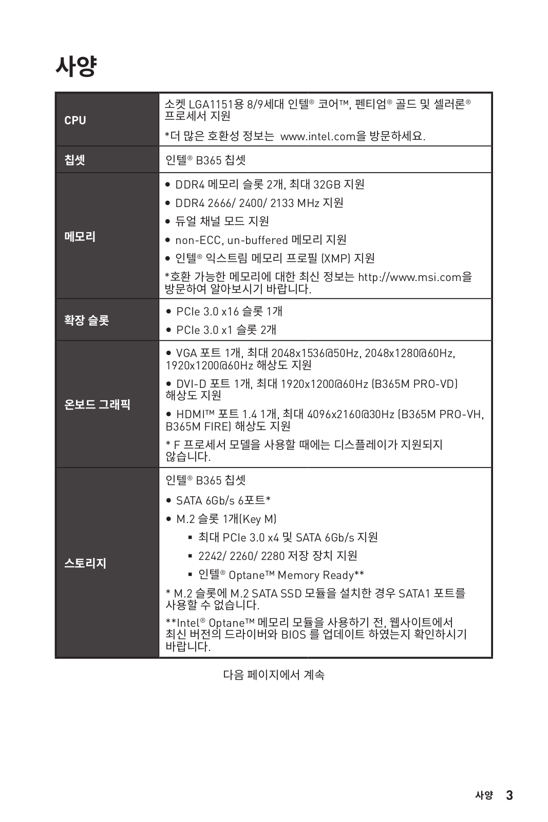
Specifications
CPU
Supports 9th/8th Gen Intel® Core™ / Pentium® Gold / Celeron®
processors for LGA 1151 socket
* Please go to www.intel.com for more compatibility
information.
Chipset Intel® B365 Chipset
Memory
y2x DDR4 memory slots, support up to 32GB
ySupports DDR4 2666/ 2400/ 2133 MHz
ySupports Dual-Channel mode
ySupports non-ECC, un-buffered memory
ySupports Intel® Extreme Memory Profile (XMP)
* Please refer www.msi.com for more information on
compatible memory.
Expansion Slots y1x PCIe 3.0 x16 slot
y2x PCIe 3.0 x1 slots
Onboard
Graphics
y1x VGA port, supports a maximum resolution of
2048×1536@50Hz, 2048×1280@60Hz, 1920×1200@60Hz (B365M
PRO-VD, B365M PRO-VH)
y1x DVI-D port, supports a maximum resolution of
1920×1200@60Hz (B365M PRO-VD)
y1x HDMI™ port 1.4, supports a maximum resolution of
4096×2160@30Hz (B365M PRO-VH, B365M WIND)
* No display support when using the processor model with
suffix F
Storage
Intel® B365 Chipset
y6x SATA 6Gb/s ports*
y1x M.2 slot (Key M) (B365M PRO-VD, B365M PRO-VH)
Supports up to PCIe 3.0 x4 and SATA 6Gb/s
Supports 2242/ 2260/ 2280 storage devices
Intel® Optane™ Memory Ready**
* The SATA1 port will be unavailable when an M.2 SATA SSD
module has been installed in the M.2 slot.
** Before using Intel® Optane™ memory modules, please
ensure that you have updated the drivers and BIOS to the
latest version from MSI website.
Continued on next page

4Specifications
Continued from previous page
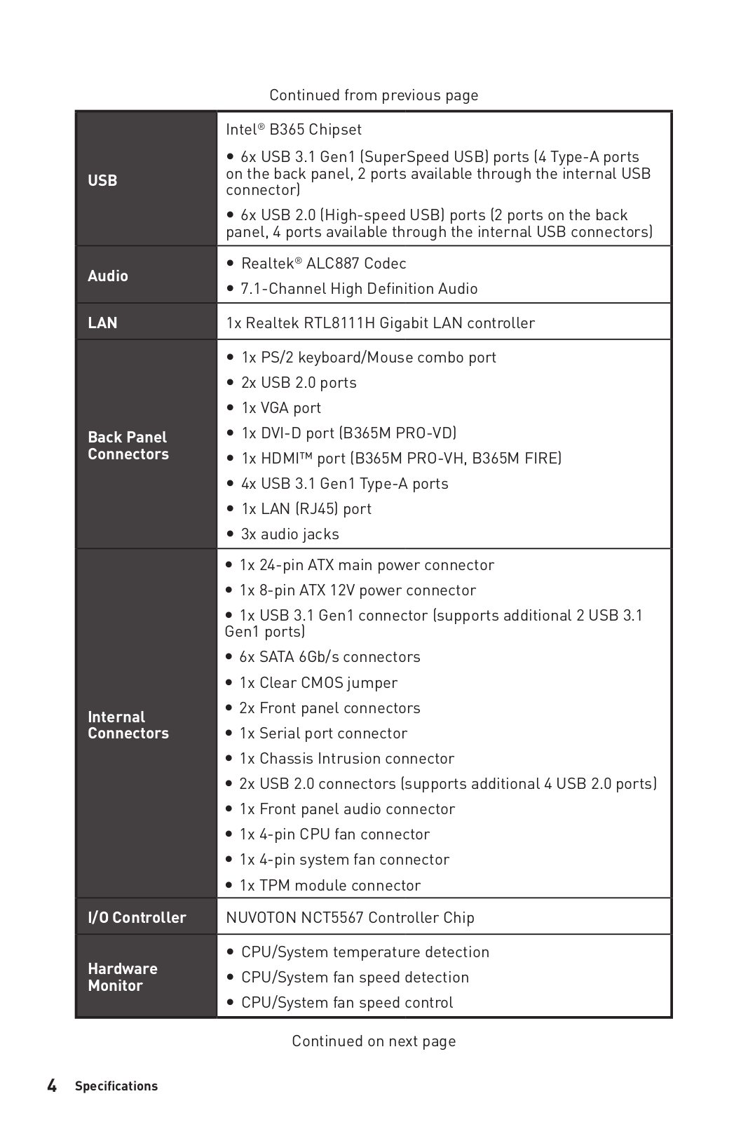
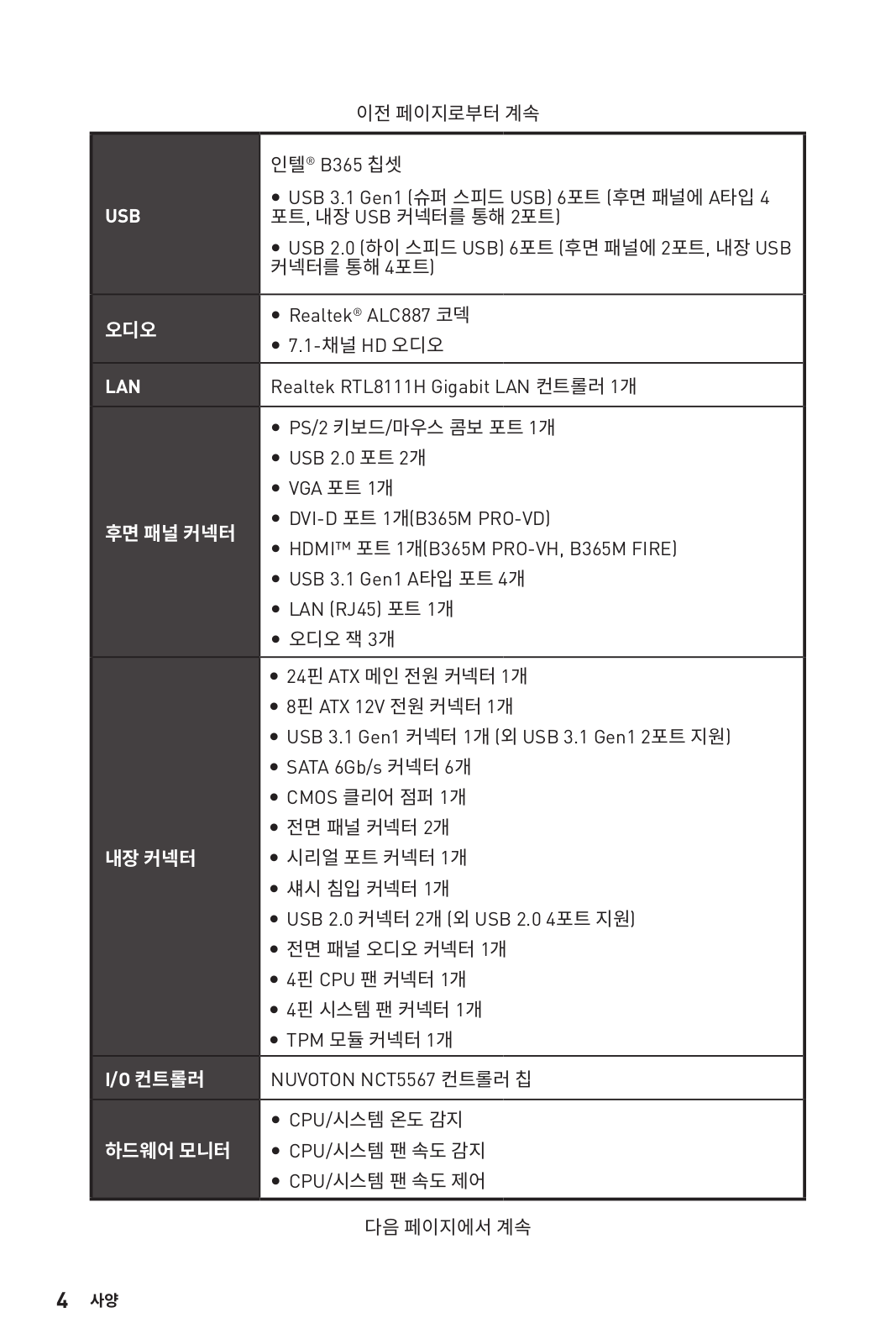
USB
Intel® B365 Chipset
y6x USB 3.1 Gen1 (SuperSpeed USB) ports (4 Type-A ports
on the back panel, 2 ports available through the internal USB
connector)
y6x USB 2.0 (High-speed USB) ports (2 ports on the back
panel, 4 ports available through the internal USB connectors)
Audio yRealtek® ALC887 Codec
y7.1-Channel High Definition Audio
LAN 1x Realtek RTL8111H Gigabit LAN controller
Back Panel
Connectors
y1x PS/2 keyboard/Mouse combo port
y2x USB 2.0 ports
y1x VGA port (B365M PRO-VD, B365M PRO-VH)
y1x DVI-D port (B365M PRO-VD)
y1x HDMI™ port (B365M PRO-VH, B365M WIND)
y4x USB 3.1 Gen1 Type-A ports
y1x LAN (RJ45) port
y3x audio jacks
Internal
Connectors
y1x 24-pin ATX main power connector
y1x 8-pin ATX 12V power connector
y1x USB 3.1 Gen1 connector (supports additional 2 USB 3.1
Gen1 ports)
y6x SATA 6Gb/s connectors
y1x Clear CMOS jumper
y2x Front panel connectors
y1x Serial port connector
y1x Chassis Intrusion connector
y2x USB 2.0 connectors (supports additional 4 USB 2.0 ports)
y1x Front panel audio connector
y1x 4-pin CPU fan connector
y1x 4-pin system fan connector
y1x TPM module connector
I/O Controller NUVOTON NCT5567 Controller Chip
Hardware
Monitor
yCPU/System temperature detection
yCPU/System fan speed detection
yCPU/System fan speed control
Continued on next page

5
Specifications Specifications
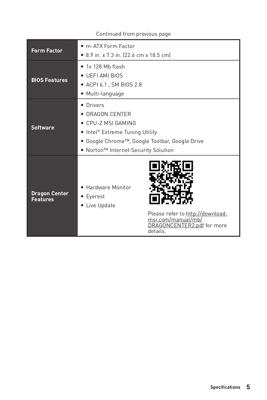
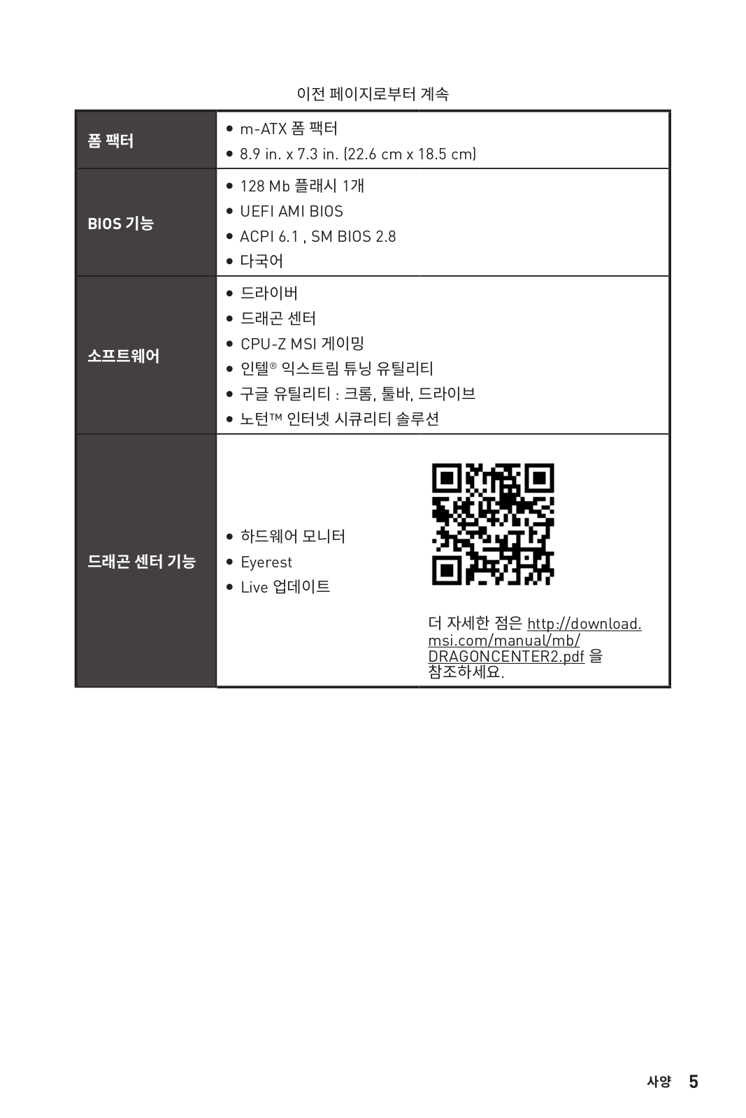
Continued from previous page
Form Factor ym-ATX Form Factor
y8.9 in. x 7.3 in. (22.6 cm x 18.5 cm)
BIOS Features
y1x 128 Mb flash
yUEFI AMI BIOS
yACPI 6.1 , SM BIOS 2.8
yMulti-language
Software
yDrivers
yDRAGON CENTER
yCPU-Z MSI GAMING
yIntel® Extreme Tuning Utility
yGoogle Chrome™, Google Toolbar, Google Drive
yNorton™ Internet Security Solution
Dragon Center
Features
yHardware Monitor
yEyerest
yLive Update
Please refer to http://download.
msi.com/manual/mb/
DRAGONCENTER2.pdf for more
details.
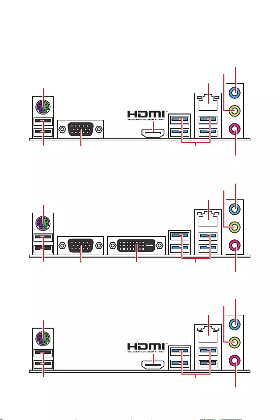
6Rear I/O Panel
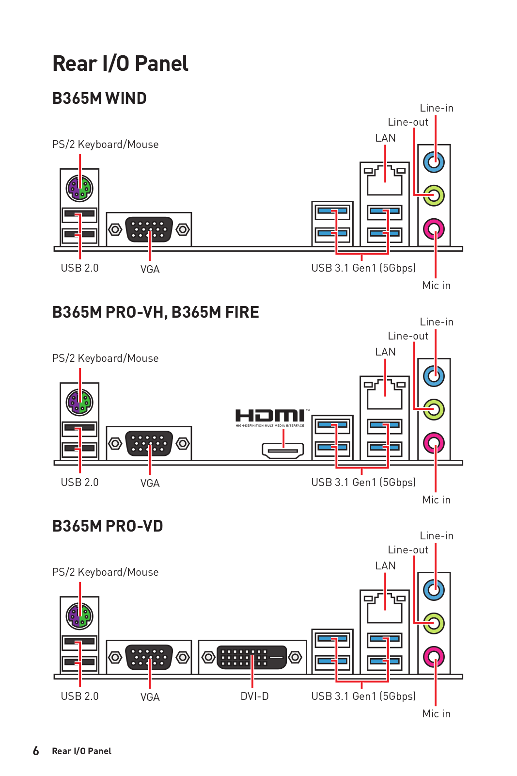
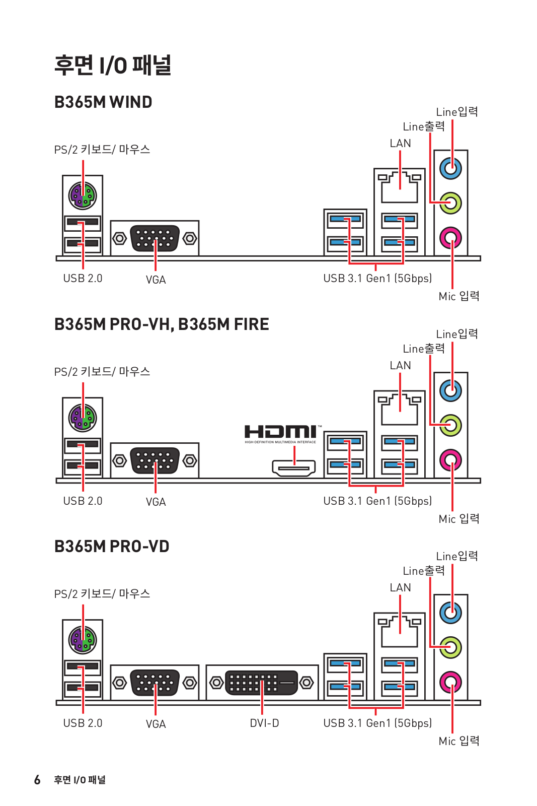
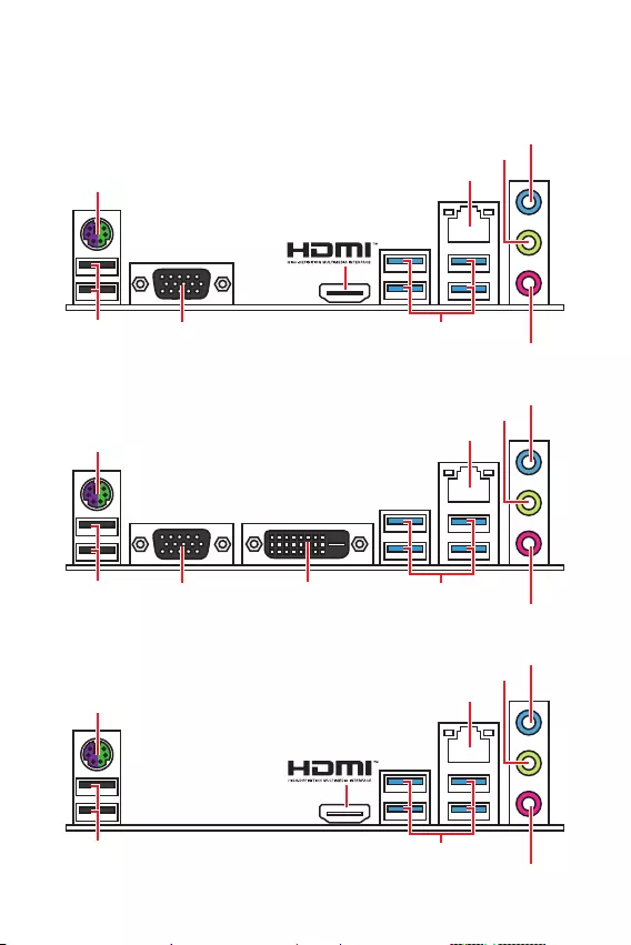
Rear I/O Panel
PS/2 Keyboard/Mouse
B365M PRO-VH
LAN
Line-in
Mic in
Line-out
USB 3.1 Gen1 (5Gbps)
VGA
USB 2.0
PS/2 Keyboard/Mouse
B365M PRO-VD
LAN
Line-in
Mic in
Line-out
USB 3.1 Gen1 (5Gbps)
VGA DVI-D
USB 2.0
PS/2 Keyboard/Mouse
B365M WIND
LAN
Line-in
Mic in
Line-out
USB 3.1 Gen1 (5Gbps)USB 2.0
7
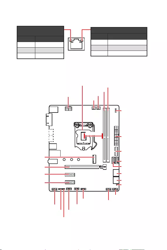
Rear I/O Panel Overview of Components
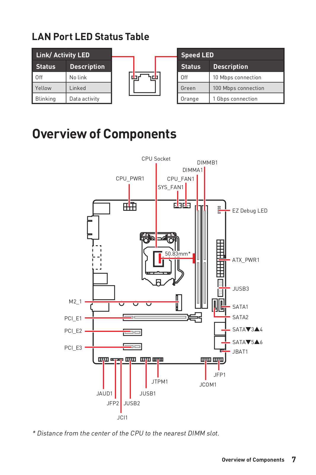
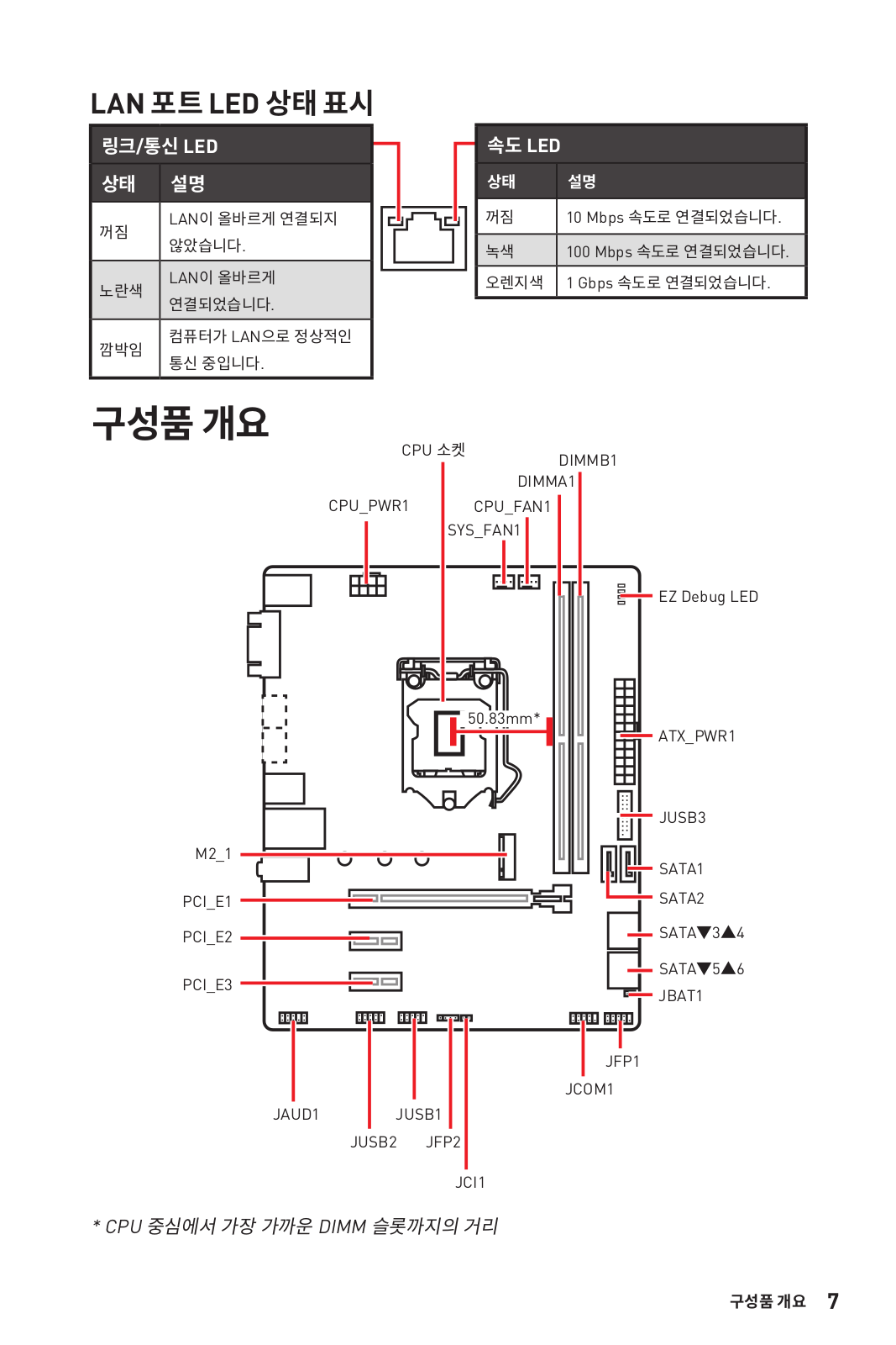
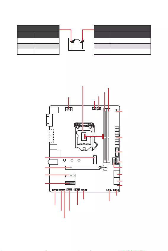
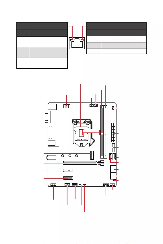
Link/ Activity LED
Status Description
Off No link
Yellow Linked
Blinking Data activity
Speed LED
Status Description
Off 10 Mbps connection
Green 100 Mbps connection
Orange 1 Gbps connection
LAN Port LED Status Table
Overview of Components
CPU_FAN1
ATX_PWR1
EZ Debug LED
CPU Socket
PCI_E1
SYS_FAN1
PCI_E2
PCI_E3
JCI1
DIMMA1
DIMMB1
SATA1
SATA2
JBAT1
JFP1
JFP2
CPU_PWR1
JUSB2
JUSB1
JTPM1
JUSB3
JCOM1
JAUD1
SATA34
SATA56
M2_1
(B365M PRO-VD,
B365M PRO-VH)
* Distance from the center of the CPU to the nearest DIMM slot.
50.83mm*

8Rear I/O Panel
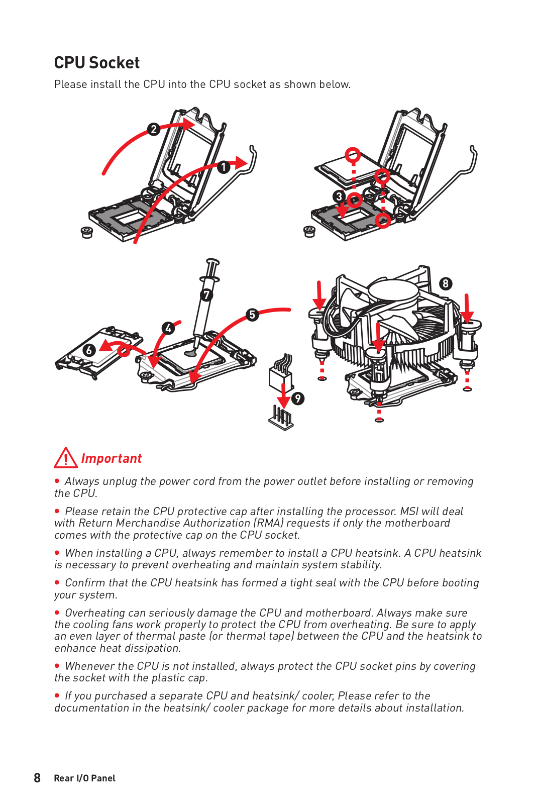
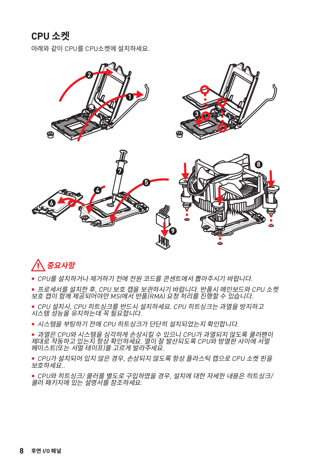
CPU Socket
Please install the CPU into the CPU socket as shown below.
Important
y
Always unplug the power cord from the power outlet before installing or removing
the CPU.
y
Please retain the CPU protective cap after installing the processor. MSI will deal
with Return Merchandise Authorization (RMA) requests if only the motherboard
comes with the protective cap on the CPU socket.
y
When installing a CPU, always remember to install a CPU heatsink. A CPU heatsink
is necessary to prevent overheating and maintain system stability.
y
Confirm that the CPU heatsink has formed a tight seal with the CPU before booting
your system.
y
Overheating can seriously damage the CPU and motherboard. Always make sure
the cooling fans work properly to protect the CPU from overheating. Be sure to apply
an even layer of thermal paste (or thermal tape) between the CPU and the heatsink to
enhance heat dissipation.
y
Whenever the CPU is not installed, always protect the CPU socket pins by covering
the socket with the plastic cap.
y
If you purchased a separate CPU and heatsink/ cooler, Please refer to the
documentation in the heatsink/ cooler package for more details about installation.
1
4
6
5
78
9
3
2

9
Rear I/O Panel Rear I/O Panel
Important
y
To boot up the system successfully, always insert the memory module into DIMMA1
first.
y
Due to chipset resource usage, the available capacity of memory will be a little less
than the amount of installed.
y
Please note that the maximum capacity of addressable memory is 4GB or
less for 32-bit Windows OS due to the memory address limitation. Therefore, we
recommended that you to install 64-bit Windows OS if you want to install more than
4GB memory on the motherboard.
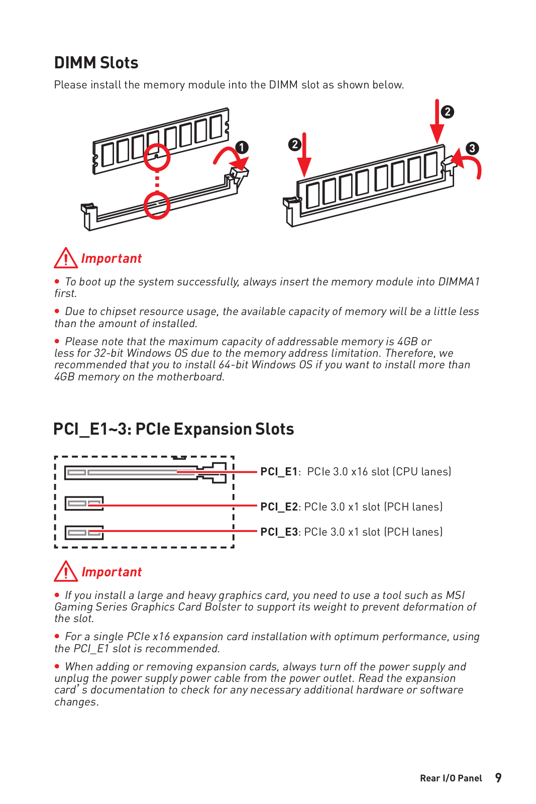
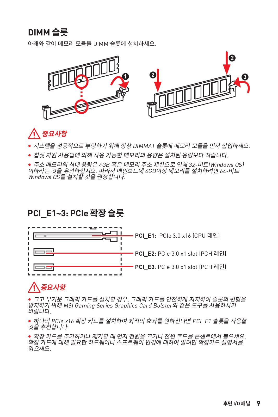
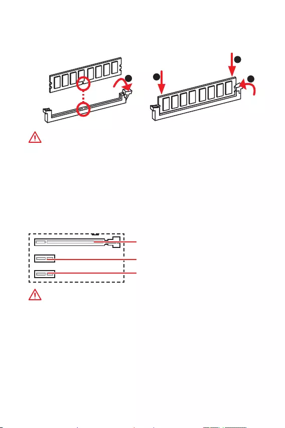
PCI_E1~3: PCIe Expansion Slots
PCI_E1: PCIe 3.0 x16 slot (CPU lanes)
PCI_E3: PCIe 3.0 x1 slot (PCH lanes)
PCI_E2: PCIe 3.0 x1 slot (PCH lanes)
Important
y
If you install a large and heavy graphics card, you need to use a tool such as MSI
Gaming Series Graphics Card Bolster to support its weight to prevent deformation of
the slot.
y
For a single PCIe x16 expansion card installation with optimum performance, using
the PCI_E1 slot is recommended.
y
When adding or removing expansion cards, always turn off the power supply and
unplug the power supply power cable from the power outlet. Read the expansion
cards documentation to check for any necessary additional hardware or software
changes.
DIMM Slots
Please install the memory module into the DIMM slot as shown below.
123
2

10 Rear I/O Panel
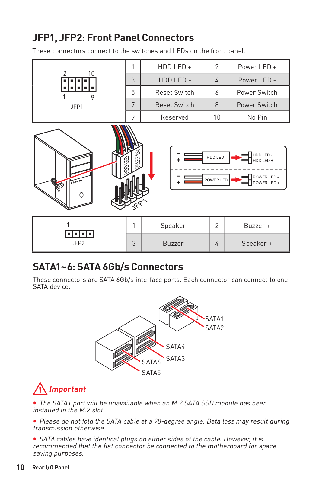
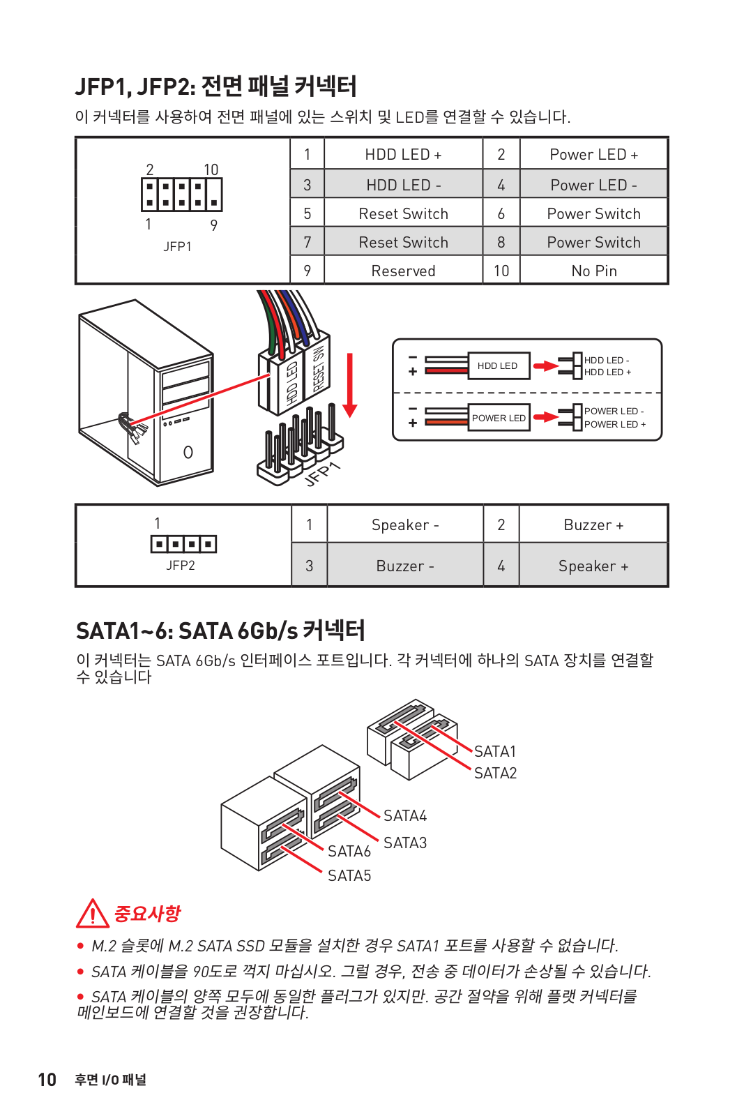
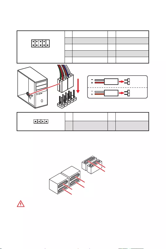
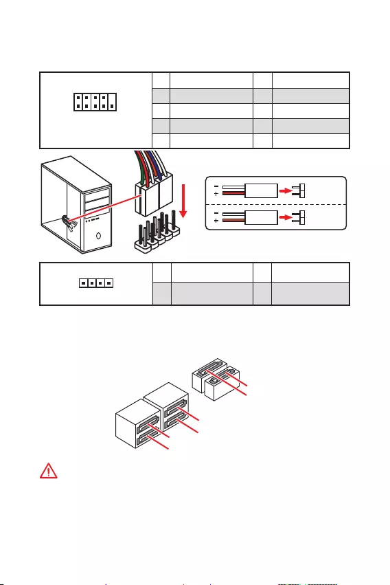
SATA1~6: SATA 6Gb/s Connectors
These connectors are SATA 6Gb/s interface ports. Each connector can connect to one
SATA device.
SATA3
SATA5
SATA4
SATA1
SATA2
SATA6
Important
y
The SATA1 port will be unavailable when an M.2 SATA SSD module has been
installed in the M.2 slot.
y
Please do not fold the SATA cable at a 90-degree angle. Data loss may result during
transmission otherwise.
y
SATA cables have identical plugs on either sides of the cable. However, it is
recommended that the flat connector be connected to the motherboard for space
saving purposes.
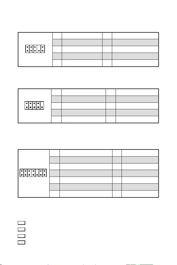
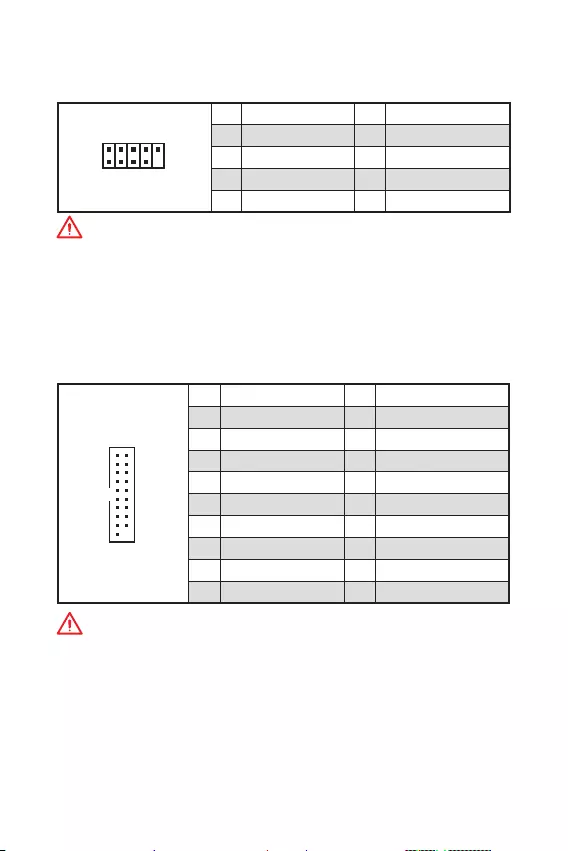
JFP1, JFP2: Front Panel Connectors
These connectors connect to the switches and LEDs on the front panel.
1
2 10
9
JFP1
1 HDD LED + 2 Power LED +
3 HDD LED — 4 Power LED —
5 Reset Switch 6 Power Switch
7 Reset Switch 8 Power Switch
9 Reserved 10 No Pin
1
JFP2
1 Speaker — 2 Buzzer +
3 Buzzer — 4 Speaker +
HDD LED
RESET SW
HDD LED HDD LED —
HDD LED +
POWER LED —
POWER LED +
POWER LED
JFP1

11
Rear I/O Panel Rear I/O Panel
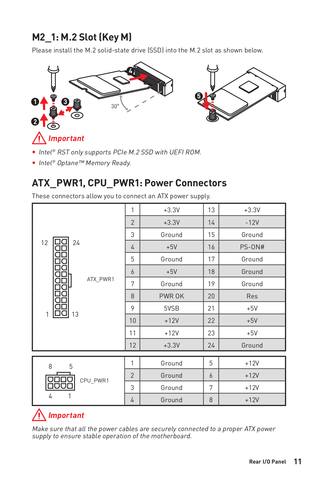
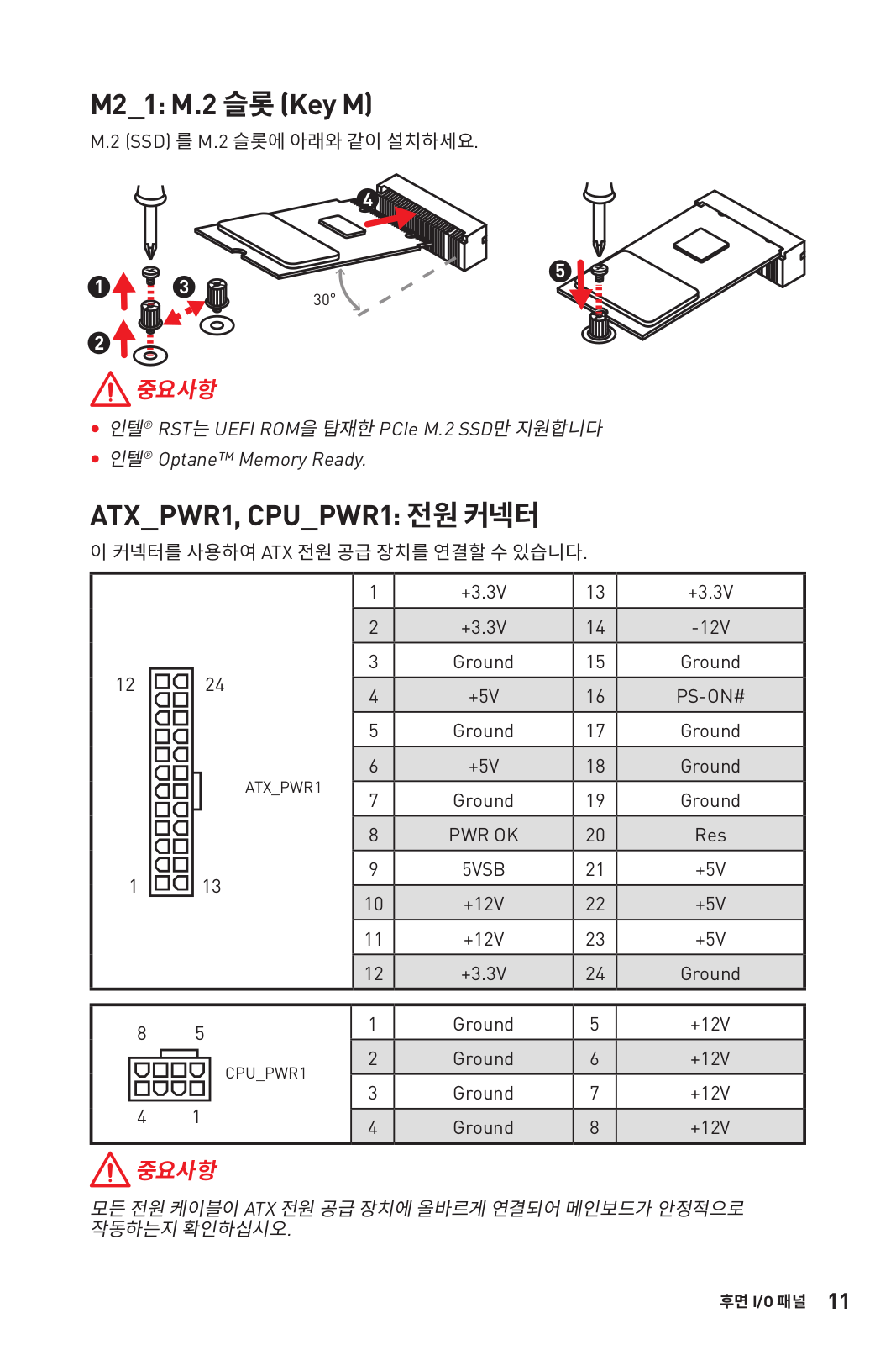
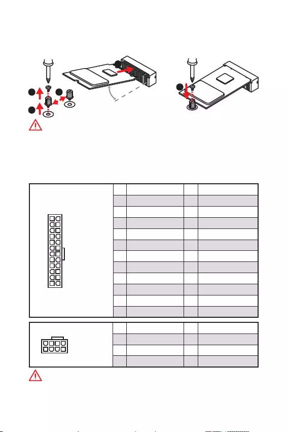
M2_1: M.2 Slot (Key M) (B365M PRO-VD, B365M PRO-VH)
Please install the M.2 solid-state drive (SSD) into the M.2 slot as shown below.
ATX_PWR1, CPU_PWR1: Power Connectors
These connectors allow you to connect an ATX power supply.
24
131
12
ATX_PWR1
1 +3.3V 13 +3.3V
2 +3.3V 14 -12V
3 Ground 15 Ground
4 +5V 16 PS-ON#
5 Ground 17 Ground
6 +5V 18 Ground
7 Ground 19 Ground
8 PWR OK 20 Res
9 5VSB 21 +5V
10 +12V 22 +5V
11 +12V 23 +5V
12 +3.3V 24 Ground
5
41
8
CPU_PWR1
1 Ground 5 +12V
2 Ground 6 +12V
3 Ground 7 +12V
4 Ground 8 +12V
Important
Make sure that all the power cables are securely connected to a proper ATX power
supply to ensure stable operation of the motherboard.
1
2
3
4
5
Important
y
Intel® RST only supports PCIe M.2 SSD with UEFI ROM.
y
Intel® Optane™ Memory Ready.
30

12 Rear I/O Panel
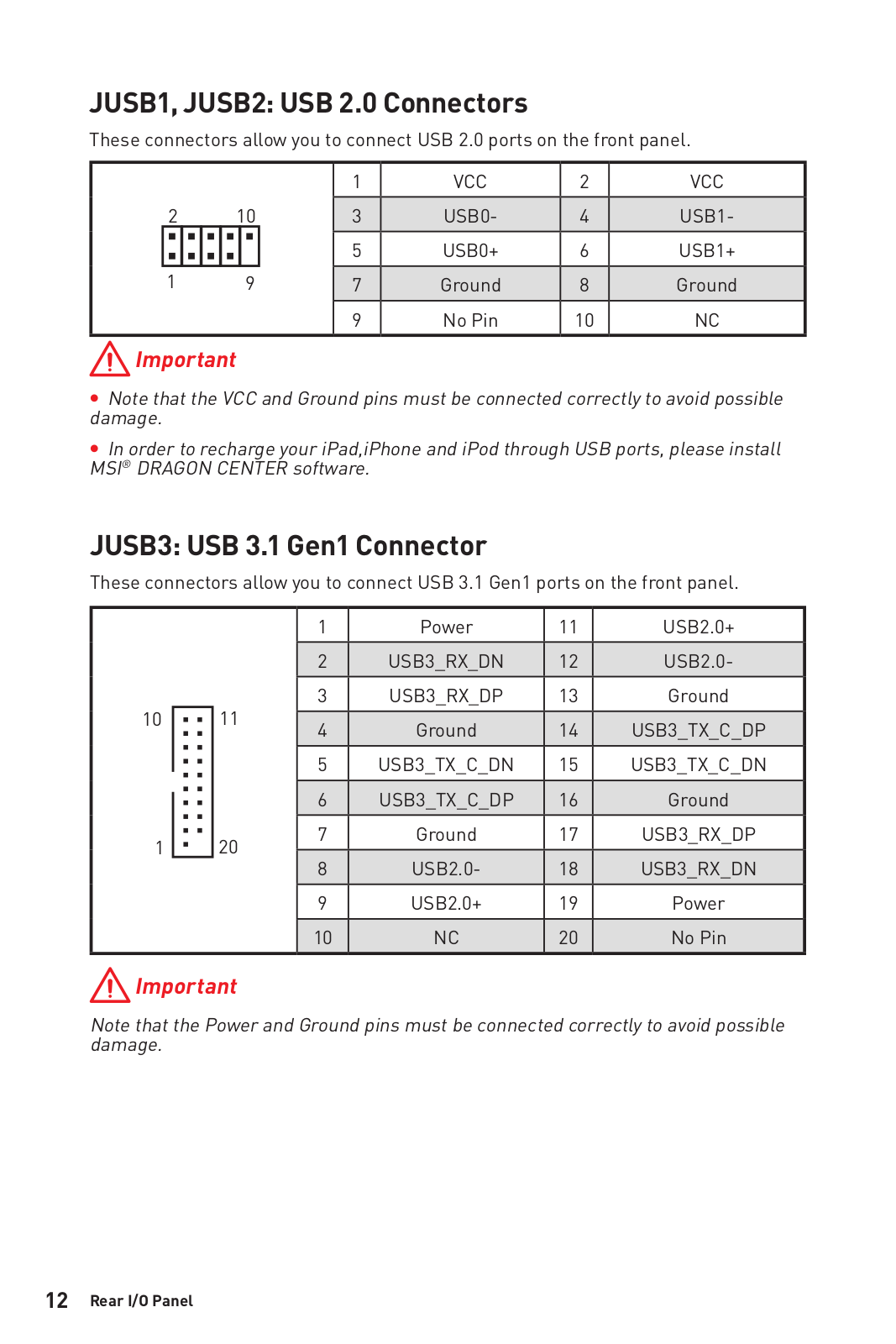
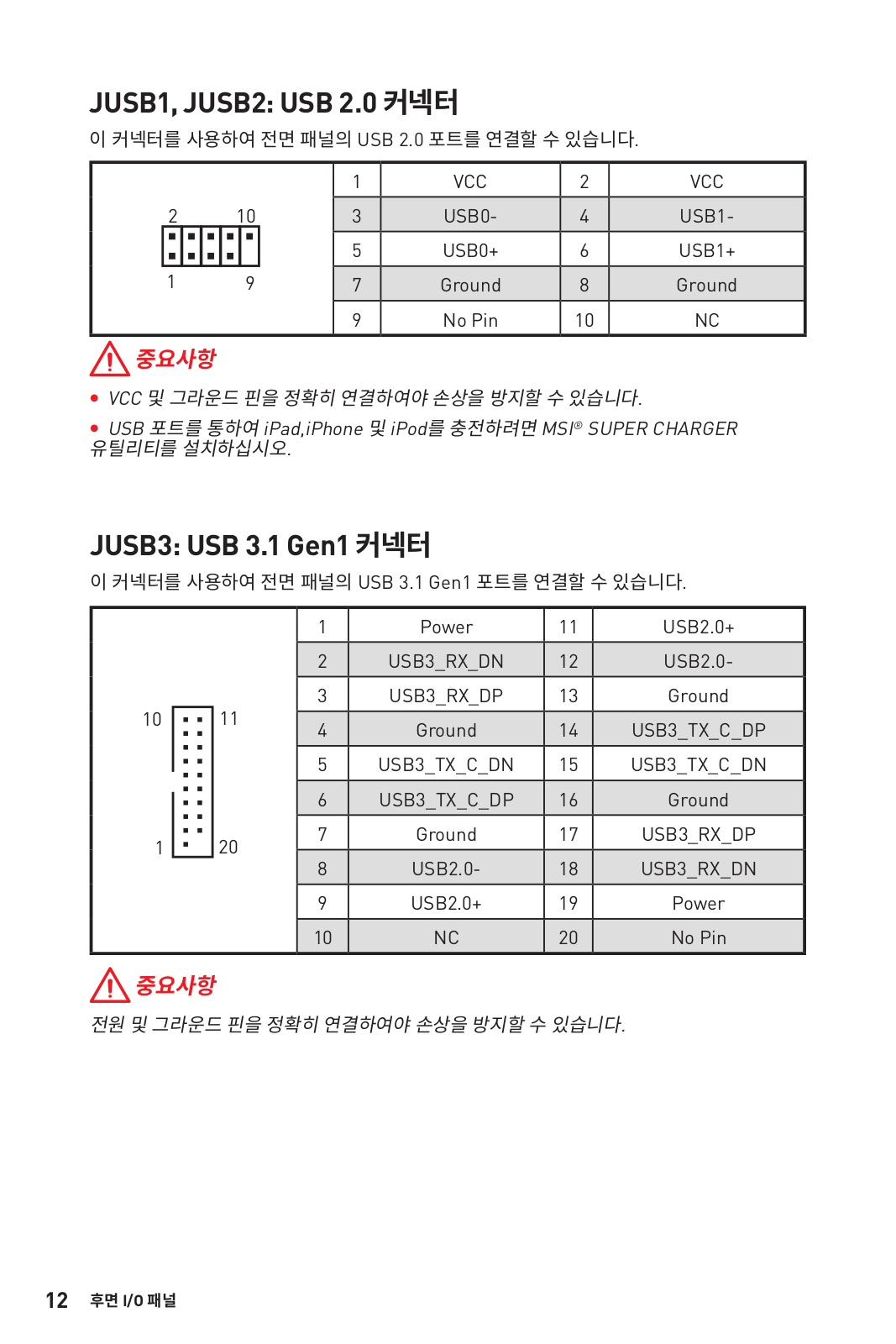
JUSB3: USB 3.1 Gen1 Connector
These connectors allow you to connect USB 3.1 Gen1 ports on the front panel.
1
10 11
20
1Power 11 USB2.0+
2 USB3_RX_DN 12 USB2.0-
3 USB3_RX_DP 13 Ground
4 Ground 14 USB3_TX_C_DP
5 USB3_TX_C_DN 15 USB3_TX_C_DN
6 USB3_TX_C_DP 16 Ground
7 Ground 17 USB3_RX_DP
8 USB2.0- 18 USB3_RX_DN
9 USB2.0+ 19 Power
10 NC 20 No Pin
Important
Note that the Power and Ground pins must be connected correctly to avoid possible
damage.
JUSB1, JUSB2: USB 2.0 Connectors
These connectors allow you to connect USB 2.0 ports on the front panel.
1
2 10
9
1VCC 2VCC
3 USB0- 4 USB1-
5 USB0+ 6 USB1+
7 Ground 8 Ground
9 No Pin 10 NC
Important
y
Note that the VCC and Ground pins must be connected correctly to avoid possible
damage.
y
In order to recharge your iPad,iPhone and iPod through USB ports, please install
MSI® DRAGON CENTER software.
13
Rear I/O Panel Rear I/O Panel
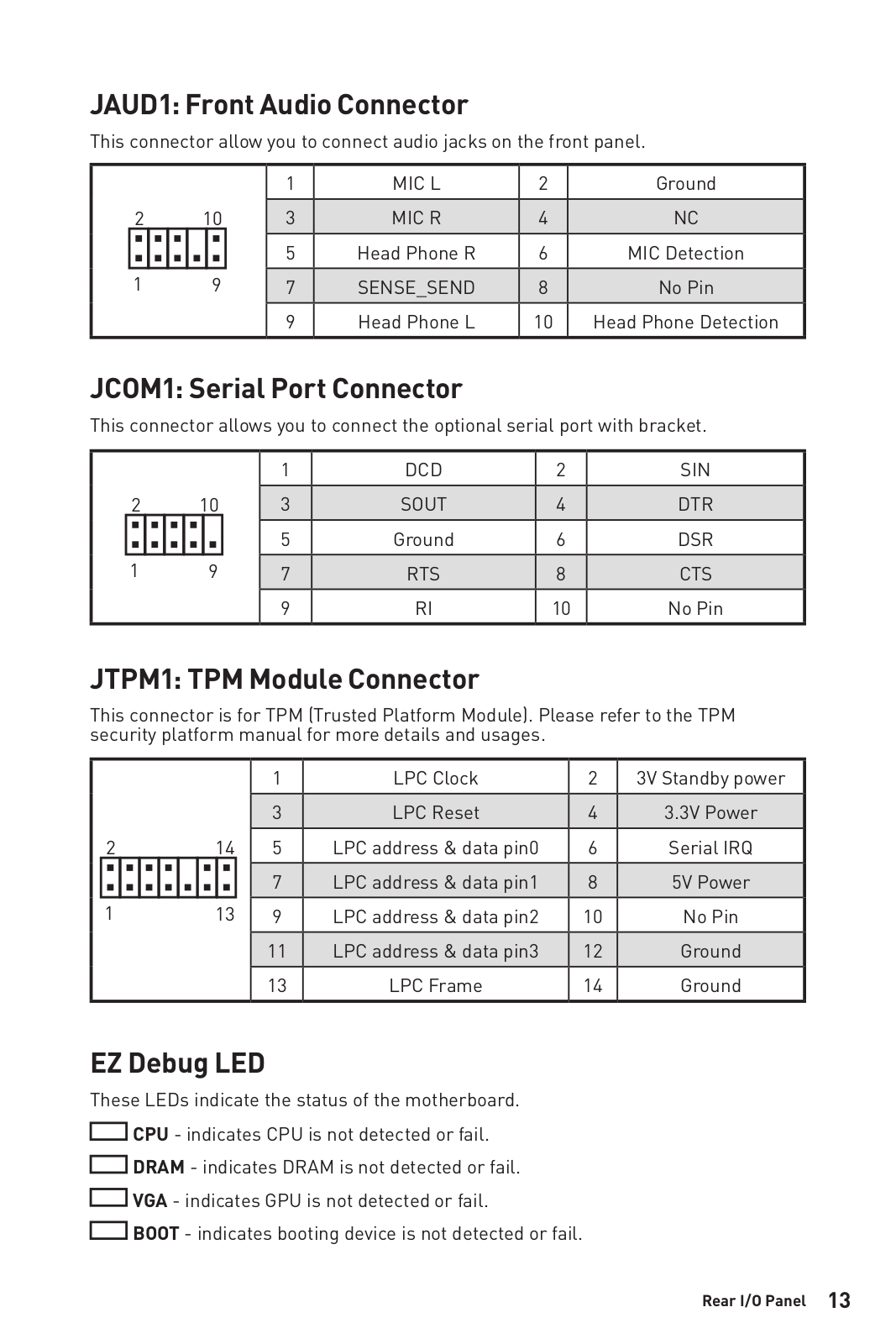
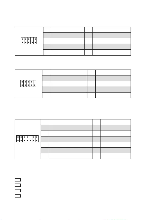
JAUD1: Front Audio Connector
This connector allow you to connect audio jacks on the front panel.
1
2 10
9
1 MIC L 2 Ground
3 MIC R 4 NC
5 Head Phone R 6 MIC Detection
7 SENSE_SEND 8 No Pin
9 Head Phone L 10 Head Phone Detection
JCOM1: Serial Port Connector
This connector allows you to connect the optional serial port with bracket.
1
2 10
9
1 DCD 2 SIN
3 SOUT 4 DTR
5 Ground 6 DSR
7 RTS 8 CTS
9 RI 10 No Pin
EZ Debug LED
These LEDs indicate the status of the motherboard.
CPU — indicates CPU is not detected or fail.
DRAM — indicates DRAM is not detected or fail.
VGA — indicates GPU is not detected or fail.
BOOT — indicates booting device is not detected or fail.
JTPM1: TPM Module Connector
This connector is for TPM (Trusted Platform Module). Please refer to the TPM
security platform manual for more details and usages.
1
2 14
13
1 LPC Clock 2 3V Standby power
3 LPC Reset 4 3.3V Power
5 LPC address & data pin0 6 Serial IRQ
7 LPC address & data pin1 8 5V Power
9 LPC address & data pin2 10 No Pin
11 LPC address & data pin3 12 Ground
13 LPC Frame 14 Ground

14 Rear I/O Panel
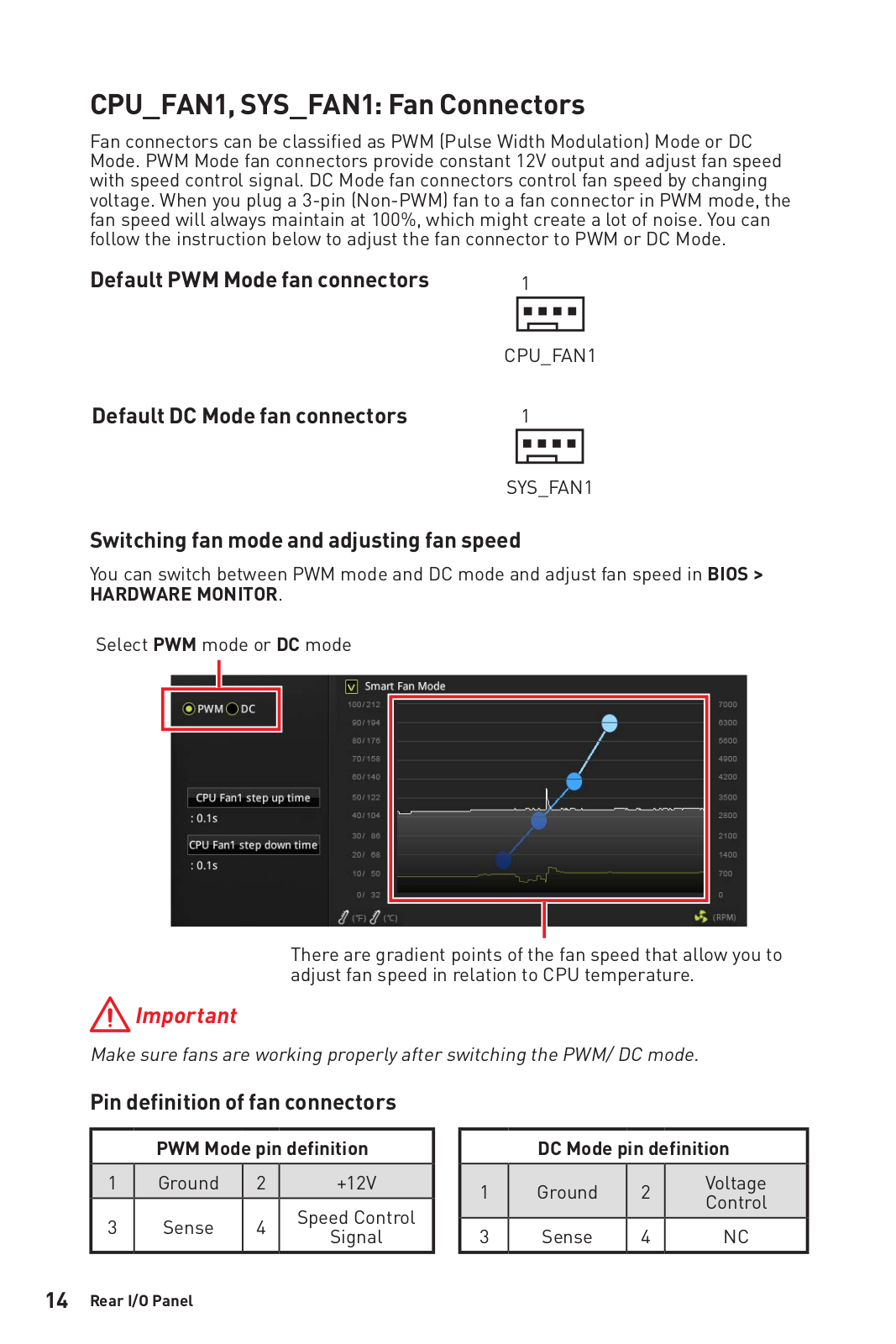
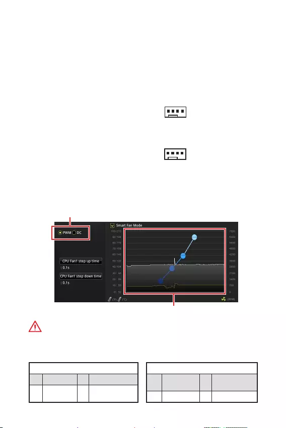
CPU_FAN1, SYS_FAN1: Fan Connectors
Fan connectors can be classified as PWM (Pulse Width Modulation) Mode or DC
Mode. PWM Mode fan connectors provide constant 12V output and adjust fan speed
with speed control signal. DC Mode fan connectors control fan speed by changing
voltage. When you plug a 3-pin (Non-PWM) fan to a fan connector in PWM mode, the
fan speed will always maintain at 100%, which might create a lot of noise. You can
follow the instruction below to adjust the fan connector to PWM or DC Mode.
PWM Mode pin definition
1 Ground 2 +12V
3 Sense 4 Speed Control
Signal
DC Mode pin definition
1 Ground 2 Voltage
Control
3 Sense 4 NC
Default PWM Mode fan connectors
Default DC Mode fan connectors
Switching fan mode and adjusting fan speed
You can switch between PWM mode and DC mode and adjust fan speed in BIOS >
HARDWARE MONITOR.
Select PWM mode or DC mode
Important
Make sure fans are working properly after switching the PWM/ DC mode.
There are gradient points of the fan speed that allow you to
adjust fan speed in relation to CPU temperature.
1
CPU_FAN1
1
SYS_FAN1
Pin definition of fan connectors

15
Rear I/O Panel Rear I/O Panel
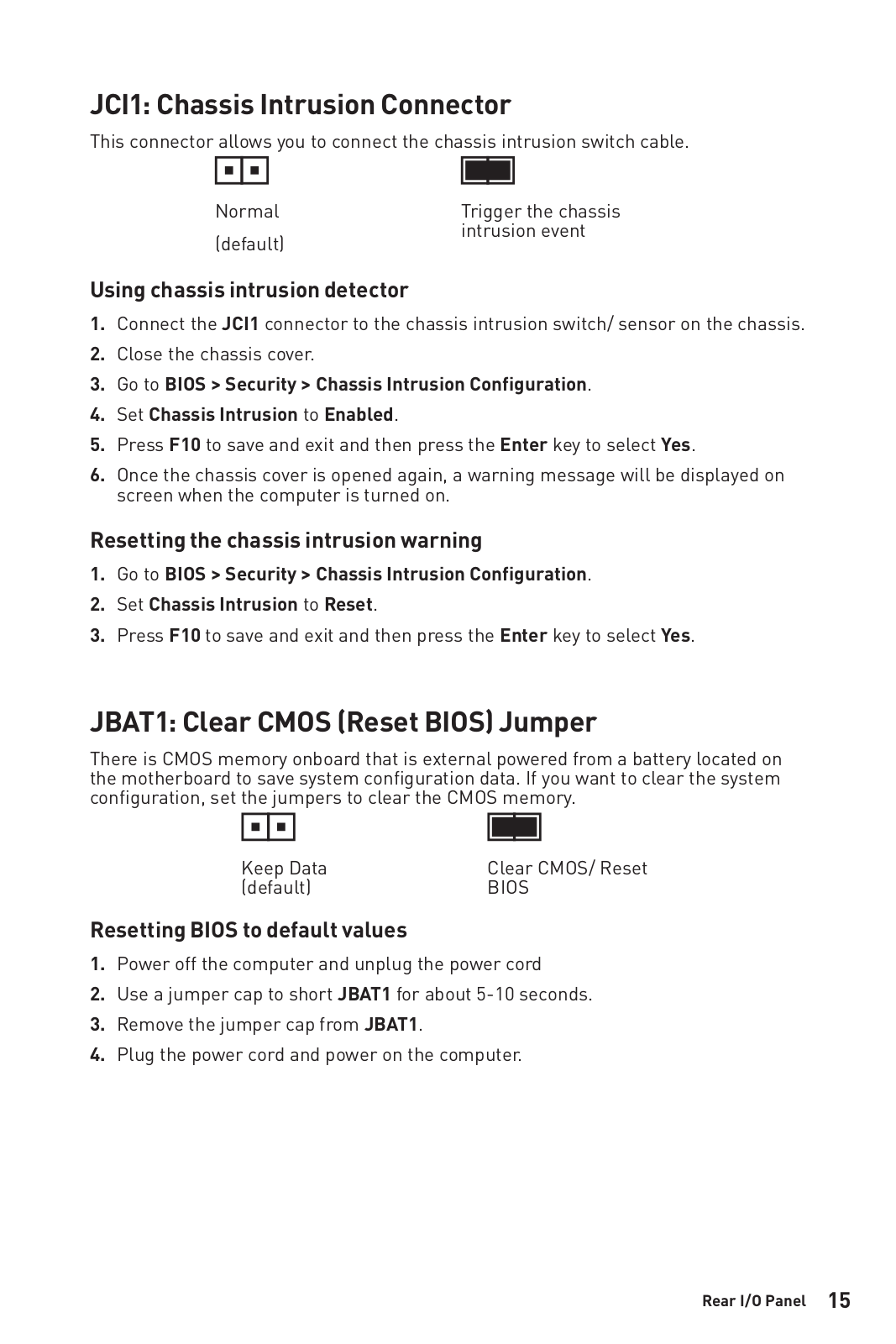
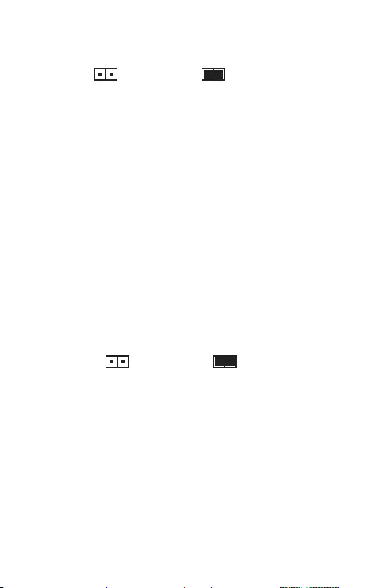
JBAT1: Clear CMOS (Reset BIOS) Jumper
There is CMOS memory onboard that is external powered from a battery located on
the motherboard to save system configuration data. If you want to clear the system
configuration, set the jumpers to clear the CMOS memory.
Keep Data
(default) Clear CMOS/ Reset
BIOS
Resetting BIOS to default values
1. Power off the computer and unplug the power cord
2. Use a jumper cap to short JBAT1 for about 5-10 seconds.
3. Remove the jumper cap from JBAT1.
4. Plug the power cord and power on the computer.
JCI1: Chassis Intrusion Connector
This connector allows you to connect the chassis intrusion switch cable.
Normal
(default)
Trigger the chassis
intrusion event
Using chassis intrusion detector
1. Connect the JCI1 connector to the chassis intrusion switch/ sensor on the chassis.
2. Close the chassis cover.
3. Go to BIOS > Security > Chassis Intrusion Configuration.
4. Set Chassis Intrusion to Enabled.
5. Press F10 to save and exit and then press the Enter key to select Yes.
6. Once the chassis cover is opened again, a warning message will be displayed on
screen when the computer is turned on.
Resetting the chassis intrusion warning
1. Go to BIOS > Security > Chassis Intrusion Configuration.
2. Set Chassis Intrusion to Reset.
3. Press F10 to save and exit and then press the Enter key to select Yes.

16 BIOS Setup
BIOS Setup
The default settings offer the optimal performance for system stability in normal
conditions. You should always keep the default settings to avoid possible system
damage or failure booting unless you are familiar with BIOS.
Important
y
BIOS items are continuously update for better system performance. Therefore, the
description may be slightly different from the latest BIOS and should be for reference
only. You could also refer to the HELP information panel for BIOS item description.
y
The pictures in this chapter are for reference only and may vary from the product
you purchased.
Entering BIOS Setup
Please refer the following methods to enter BIOS setup.
yPress Delete key, when the Press DEL key to enter Setup Menu, F11 to enter Boot
Menu message appears on the screen during the boot process.
yUse MSI DRAGON CENTER application. Click on GO2BIOS button and choose OK.
The system will reboot and enter BIOS setup directly.
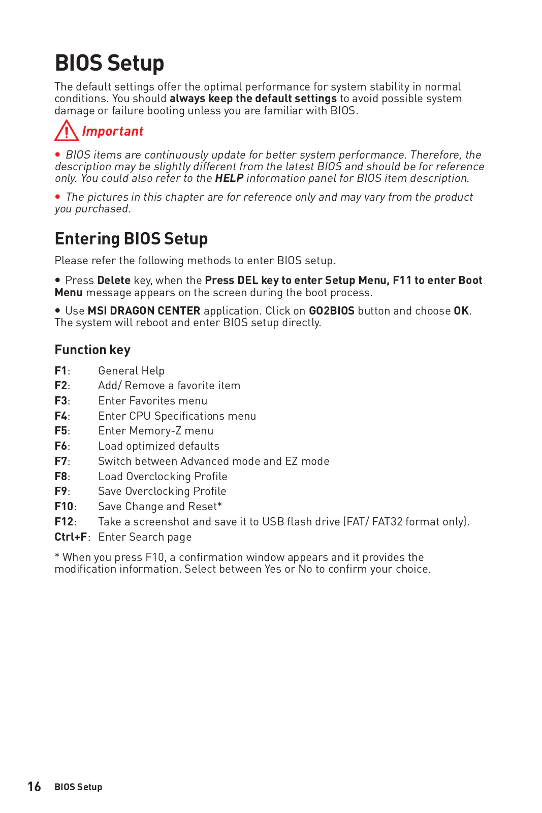
Function key
F1: General Help
F2: Add/ Remove a favorite item
F3: Enter Favorites menu
F4: Enter CPU Specifications menu
F5: Enter Memory-Z menu
F6: Load optimized defaults
F7: Switch between Advanced mode and EZ mode
F8: Load Overclocking Profile
F9: Save Overclocking Profile
F10: Save Change and Reset*
F12: Take a screenshot and save it to USB flash drive (FAT/ FAT32 format only).
Ctrl+F: Enter Search page
* When you press F10, a confirmation window appears and it provides the
modification information. Select between Yes or No to confirm your choice.

17
BIOS Setup BIOS Setup
Resetting BIOS
You might need to restore the default BIOS setting to solve certain problems. There
are several ways to reset BIOS:
yGo to BIOS and press F6 to load optimized defaults.
yShort the Clear CMOS jumper on the motherboard.
Important
Be sure the computer is off before clearing CMOS data. Please refer to the Clear
CMOS jumper section for resetting BIOS.
Updating BIOS
Updating BIOS with M—FLASH
Before updating:
Please download the latest BIOS file that matches your motherboard model from MSI
website. And then save the BIOS file into the USB flash drive.
Updating BIOS:
1. Press Del key to enter the BIOS Setup during POST.
2. Insert the USB flash drive that contains the update file into the computer.
3. Select the M-FLASH tab and click on Yes to reboot the system and enter the flash
mode.
4. Select a BIOS file to perform the BIOS update process.
5. After the flashing process is 100% completed, the system will reboot
automatically.
Updating the BIOS with MSI DRAGON CENTER
Before updating:
Make sure the LAN driver is already installed and the Internet connection is set
properly.
Updating BIOS:
1. Install and launch MSI DRAGON CENTER.
2. Select BIOS Update.
3. Click on Scan button.
4. Click on Download icon to download and install the latest BIOS file.
5. Click Next and choose In Windows mode. And then click Next and Start to start
updating BIOS.
6. After the flashing process is 100% completed, the system will restart
automatically.

18 Installing OS, Drivers & Utilities
Installing OS, Drivers & Utilities
Please download and update the latest utilities and drivers at www.msi.com
Installing Windows® 10
1. Power on the computer.
2. Insert the Windows® 10 installation disc/USB into your computer.
3. Press the Restart button on the computer case.
4. Press F11 key during the computer POST (Power-On Self Test) to get into Boot
Menu.
5. Select the Windows® 10 installation disc/USB from the Boot Menu.
6. Press any key when screen shows Press any key to boot from CD or DVD…
message.
7. Follow the instructions on the screen to install Windows® 10.
Installing Drivers
1. Start up your computer in Windows® 10.
2. Insert MSI® Driver Disc into your optical drive.
3. Click the Select to choose what happens with this disc pop-up notification, then
select Run DVDSetup.exe to open the installer. If you turn off the AutoPlay feature
from the Windows Control Panel, you can still manually execute the DVDSetup.exe
from the root path of the MSI Driver Disc.
4. The installer will find and list all necessary drivers in the Drivers/Software tab.
5. Click the Install button in the lower-right corner of the window.
6. The drivers installation will then be in progress, after it has finished it will prompt
you to restart.
7. Click OK button to finish.
8. Restart your computer.
Installing Utilities
Before you install utilities, you must complete drivers installation.
1. Open the installer as described above.
2. Click the Utilities tab.
3. Select the utilities you want to install.
4. Click the Install button in the lower-right corner of the window.
5. The utilities installation will then be in progress, after it has finished it will prompt
you to restart.
6. Click OK button to finish.
7. Restart your computer.

1
< 1>
…………………………………………………………………………………………….. 2
…………………………………………………………………………………………………….3
I/O ………………………………………………………………………………………..6
B365M PRO-VH ………………………………………………………………………………………6
B365M PRO-VD ………………………………………………………………………………………6
B365M WIND ………………………………………………………………………………………….6
LAN LED ……………………………………………………………………………7
…………………………………………………………………………………………..7
CPU ………………………………………………………………………………………………..8
DIMM ……………………………………………………………………………………………..9
PCI_E1~3: PCIe …………………………………………………………………………9
JFP1, JFP2: ………………………………………………………………….10
SATA1~6: SATA 6Gb/s ………………………………………………………………….10
M2_1: M.2 (Key M) (B365M PRO-VD, B365M PRO-VH) ………………………..11
ATX_PWR1, CPU_PWR1: ………………………………………………………. 11
JUSB1, JUSB2: USB 2.0 ……………………………………………………………….12
JUSB3: USB 3.1 Gen1 ………………………………………………………………….12
JAUD1: ……………………………………………………………………..13
JCOM1: ……………………………………………………………………..13
JTPM1: TPM ………………………………………………………………………..13
EZ LED ………………………………………………………………………………………13
CPU_FAN1, SYS_FAN1: ……………………………………………………………14
JCI1: …………………………………………………………………………….15
JBAT1: CMOS (Reset BIOS) …………………………………………………… 15
BIOS …………………………………………………………………………………………..16
BIOS ……………………………………………………………………………………………..16
BIOS() ……………………………………………………………………………….17
BIOS() …………………………………………………………………………17
OS, & …………………………………………………………. 18
Windows® 10 ……………………………………………………………..18
………………………………………………………………………………….18
………………………………………………………………………………….18
MSI® B365M PRO-VD/ B365M PRO-VH/ B365M WIND
.
, , BIOS
.

2
y (ESD)
.
y . ,
.
y
.
y ESD
. ESD ,
.
y
.
y
.
y . ,
.
y .
y
.
y .
y .
yPSU PSU
.
y . .
y .
y , .:
.
.
.
.
.
y 60C(140F) . .

3
CPU
LGA1151 8/9 ® ™, ® ®
* www.intel.com .
® B365
yDDR4 2, 32GB
yDDR4 2666/ 2400/ 2133 MHz
y
ynon-ECC, un-buffered
y® (XMP)
* http://www.msi.com
.
yPCIe 3.0 x16 1
yPCIe 3.0 x1 2
yVGA 1, 2048×1536@50Hz, 2048×1280@60Hz,
1920×1200@60Hz (B365M PRO-VD, B365M PRO-VH)
yDVI-D 1, 1920×1200@60Hz (B365M PRO-VD)
yHDMI™ 1.4 1, 4096×2160@30Hz (B365M PRO-VH,
B365M WIND)
* F
.
® B365
ySATA 6Gb/s 6*
yM.2 1(Key M) (B365M PRO-VD, B365M PRO-VH)
PCIe 3.0 x4 SATA 6Gb/s
2242/ 2260/ 2280
® Optane™ Memory Ready**
* M.2 M.2 SATA SSD SATA1
.
**Intel® Optane™ ,
BIOS
.

4
USB
® B365
yUSB 3.1 Gen1 ( USB) 6 ( A 4
, USB 2)
yUSB 2.0 ( USB) 6 ( 2, USB
4)
yRealtek® ALC887
y7.1- HD
LAN Realtek RTL8111H Gigabit LAN 1
yPS/2 / 1
yUSB 2.0 2
yVGA 1(B365M PRO-VD, B365M PRO-VH)
yDVI-D 1(B365M PRO-VD)
yHDMI™ 1(B365M PRO-VH, B365M WIND)
yUSB 3.1 Gen1 A 4
yLAN (RJ45) 1
y 3
y24 ATX 1
y8 ATX 12V 1
yUSB 3.1 Gen1 1 ( USB 3.1 Gen1 2 )
ySATA 6Gb/s 6
yCMOS 1
y 2
y 1
y 1
yUSB 2.0 2 ( USB 2.0 4 )
y 1
y4 CPU 1
y4 1
yTPM 1
I/O NUVOTON NCT5567
yCPU/
yCPU/
yCPU/
5
ym-ATX
y8.9 in. x 7.3 in. (22.6 cm x 18.5 cm)
BIOS
y128 Mb 1
yUEFI AMI BIOS
yACPI 6.1 , SM BIOS 2.8
y
y
y
yCPU-Z MSI
y®
y : , ,
y™
y
yEyerest
yLive
http://download.
msi.com/manual/mb/
DRAGONCENTER2.pdf
.
6 I/O
I/O
PS/2 /
B365M PRO-VH
LAN
Line
Mic
Line
USB 3.1 Gen1 (5Gbps)
VGA
USB 2.0
PS/2 /
B365M WIND
LAN
Line
Mic
Line
USB 3.1 Gen1 (5Gbps)USB 2.0
PS/2 /
B365M PRO-VD
LAN
Line
Mic
Line
USB 3.1 Gen1 (5Gbps)
VGA DVI-D
USB 2.0
7
I/O
LAN LED
CPU_FAN1
ATX_PWR1
EZ Debug LED
CPU
PCI_E1
SYS_FAN1
PCI_E2
PCI_E3
JCI1
DIMMA1
DIMMB1
SATA1
SATA2
JBAT1
JFP1
JFP2
CPU_PWR1
JUSB2
JUSB1
JUSB3
JCOM1
JAUD1
SATA34
SATA56
* CPU DIMM
50.83mm*
/ LED
LAN
.
LAN
.
LAN
.
LED
10 Mbps .
100 Mbps .
1 Gbps .
M2_1
(B365M PRO-VD,
B365M PRO-VH)

8 I/O
CPU
CPU CPU .
y
CPU .
y
, CPU . CPU
MSI (RMA) .
y
CPU , CPU . CPU
.
y
CPU .
y
CPU CPU
. CPU
( ) .
y
CPU , CPU
..
y
CPU / , /
.
1
4
6
5
78
9
3
2
9
I/O I/O
y
DIMMA1 .
y
.
y
4GB 32-(Windows OS)
. 4GB 64-
Windows OS .
PCI_E1~3: PCIe
PCI_E1: PCIe 3.0 x16 (CPU )
PCI_E3: PCIe 3.0 x1 slot (PCH )
PCI_E2: PCIe 3.0 x1 slot (PCH )
y
,
MSI Gaming Series Graphics Card Bolster
.
y
PCIe x16 PCI_E1
.
y
.
.
DIMM
DIMM .
123
2
10 I/O
SATA1~6: SATA 6Gb/s
SATA 6Gb/s . SATA
SATA3
SATA5
SATA4
SATA1
SATA2
SATA6
y
M.2 M.2 SATA SSD SATA1 .
y
SATA 90 . , .
y
SATA .
.
JFP1, JFP2:
LED .
1
2 10
9
JFP1
1 HDD LED + 2 Power LED +
3 HDD LED — 4 Power LED —
5 Reset Switch 6 Power Switch
7 Reset Switch 8 Power Switch
9 Reserved 10 No Pin
1
JFP2
1 Speaker — 2 Buzzer +
3 Buzzer — 4 Speaker +
HDD LED
RESET SW
HDD LED HDD LED —
HDD LED +
POWER LED —
POWER LED +
POWER LED
JFP1

11
I/O I/O
M2_1: M.2 (Key M) (B365M PRO-VD, B365M PRO-VH)
M.2 (SSD) M.2 .
ATX_PWR1, CPU_PWR1:
ATX .
24
131
12
ATX_PWR1
1 +3.3V 13 +3.3V
2 +3.3V 14 -12V
3 Ground 15 Ground
4 +5V 16 PS-ON#
5 Ground 17 Ground
6 +5V 18 Ground
7 Ground 19 Ground
8 PWR OK 20 Res
9 5VSB 21 +5V
10 +12V 22 +5V
11 +12V 23 +5V
12 +3.3V 24 Ground
5
41
8
CPU_PWR1
1 Ground 5 +12V
2 Ground 6 +12V
3 Ground 7 +12V
4 Ground 8 +12V
ATX
.
1
2
3
4
5
y
® RST UEFI ROM PCIe M.2 SSD
y
® Optane™ Memory Ready.
30

12 I/O
JUSB3: USB 3.1 Gen1
USB 3.1 Gen1 .
1
10 11
20
1Power 11 USB2.0+
2 USB3_RX_DN 12 USB2.0-
3 USB3_RX_DP 13 Ground
4 Ground 14 USB3_TX_C_DP
5 USB3_TX_C_DN 15 USB3_TX_C_DN
6 USB3_TX_C_DP 16 Ground
7 Ground 17 USB3_RX_DP
8 USB2.0- 18 USB3_RX_DN
9 USB2.0+ 19 Power
10 NC 20 No Pin
.
JUSB1, JUSB2: USB 2.0
USB 2.0 .
1
2 10
9
1VCC 2VCC
3 USB0- 4 USB1-
5 USB0+ 6 USB1+
7 Ground 8 Ground
9 No Pin 10 NC
y
VCC .
y
USB iPad,iPhone iPod MSI® SUPER CHARGER
.
13
I/O I/O
JAUD1:
.
1
2 10
9
1 MIC L 2 Ground
3 MIC R 4 NC
5 Head Phone R 6 MIC Detection
7 SENSE_SEND 8 No Pin
9 Head Phone L 10 Head Phone Detection
JCOM1:
.
1
2 10
9
1 DCD 2 SIN
3 SOUT 4 DTR
5 Ground 6 DSR
7 RTS 8 CTS
9 RI 10 No Pin
EZ LED
LED .
CPU — CPU .
DRAM — DRAM .
VGA — VGA .
BOOT — .
JTPM1: TPM
TPM (Trusted Platform Module) .
TPM .
1
2 14
13
1 LPC Clock 2 3V Standby power
3 LPC Reset 4 3.3V Power
5 LPC address & data pin0 6 Serial IRQ
7 LPC address & data pin1 8 5V Power
9 LPC address & data pin2 10 No Pin
11 LPC address & data pin3 12 Ground
13 LPC Frame 14 Ground

14 I/O
CPU_FAN1, SYS_FAN1:
PWM (Pulse Width Modulation) DC .
PWM 12V
. DC .
PWM 3- (Non-PWM) , 100%
. PWM DC
.
PWM
1 Ground 2 +12V
3 Sense 4 Speed Control
Signal
DC
1 Ground 2 Voltage
Control
3 Sense 4 NC
PWM
DC
PWM DC BIOS > HARDWARE MONITOR(
) .
PWM DC
PWM/ DC , .
CPU .
1
CPU_FAN1
1
SYS_FAN1
15
I/O I/O
JBAT1: CMOS (Reset BIOS)
CMOS
. CMOS
.
( )CMOS /
BIOS
BIOS()
1.
2. JBAT1 5-10 .
3. JBAT1 .
4. .
JCI1:
.
( )
1. JCI1 / .
2. .
3. BIOS > Security () > Chassis Intrusion Configuration( )
.
4. Chassis Intrusion( ) Enabled() .
5. F10 . Enter Yes .
6. .
1. BIOS > Security() > Chassis Intrusion Configuration( )
.
2. Chassis Intrusion( ) Reset() .
3. F10 . Enter Yes .

16 BIOS
BIOS
. BIOS
,
.
BIOS .
BIOS . BIOS
HELP() .
y
.
BIOS
BIOS .
y DEL , F11
Delete .
yMSI GO2BIOS OK() .
BIOS .
F1:
F2: /
F3:
F4: CPU
F5: Memory-Z(-Z)
F6:
F7: EZ
F8:
F9:
F10: *
F12: USB (FAT/ FAT32 )
Ctrl+F:
* F10 . Yes()
No() .

17
BIOS BIOS
BIOS()
BIOS . BIOS
.
yBIOS F6 .
y CMOS .
CMOS . BIOS
CMOS .
BIOS()
M-FLASH BIOS
:
BIOS MSI® BIOS USB
.
BIOS :
1. POST Del BIOS .
2. USB .
3. M-FLASH Yes
.
4. BIOS BIOS .
5. 100% .
MSI BIOS
:
LAN .
BIOS :
1. MSI .
2. BIOS Update .
3. Scan .
4. Download BIOS .
5. Next In Windows mode Next Start BIOS
.
6. 100% .

18 OS, &
OS, &
www.msi.com
.
Windows® 10
1. .
2. Windows® 10 /USB .
3. Restart .
4. POST (Power-On Self Test) F11 .
5. Windows® 10 /USB .
6. Press any key to boot from CD or DVD…
.
7. Windows® 10 .
1. Windows® 10 .
2. MSI® .
3. Select to choose what happens with this disc , Run DVD
Setup.exe .
MSI DVDSetup.exe
.
4. Drivers/Software .
5. Install .
6. . .
7. OK .
8. .
.
1. .
2. Utilities .
3. .
4. Install .
5. . .
6. OK .
7. .

1
< 1> Table des matières
Table des matières
Informations de sécurité ……………………………………………………………………… 2
Spécifications ………………………………………………………………………………………3
Panneau arrière Entrée/ Sortie …………………………………………………………….6
B365M PRO-VH ………………………………………………………………………………………6
B365M PRO-VD ………………………………………………………………………………………6
B365M WIND ………………………………………………………………………………………….6
Tableau explicatif de létat de la LED du port LAN ……………………………………..7
Vue densemble des composants ………………………………………………………….7
Socket processeur ………………………………………………………………………………….8
Slots DIMM ……………………………………………………………………………………………9
PCI_E1~3 : Slots dextension PCIe …………………………………………………………..9
JFP1, JFP2 : Connecteurs de panneau avant ……………………………………………10
SATA1~6 : Connecteurs SATA 6Gb/s………………………………………………………..10
M2_1 : Slot M.2 (Touche M) (B365M PRO-VD, B365M PRO-VH) …………………..11
ATX_PWR1, CPU_PWR1 : Connecteurs dalimentation …………………………….11
JUSB1, JUSB2 : Connecteurs USB 2.0 …………………………………………………….12
JUSB3 : Connecteur USB 3.1 Gen1 …………………………………………………………12
JAUD1 : Connecteur audio avant …………………………………………………………….13
JCOM1 : Connecteur de port série ………………………………………………………….13
JTPM1 : Connecteur de module TPM ………………………………………………………13
EZ Debug LED ………………………………………………………………………………………13
CPU_FAN1, SYS_FAN1 : Connecteurs pour ventilateurs ……………………………14
JCI1 : Connecteur intrusion châssis ………………………………………………………..15
JBAT1 : Cavalier Clear CMOS (Réinitialisation BIOS) …………………………………15
Configuration du BIOS ……………………………………………………………………….. 16
Entrer dans linterface Setup du BIOS ……………………………………………………16
Réinitialiser le BIOS ………………………………………………………………………………17
Mettre le BIOS à jour……………………………………………………………………………..17
Installer OS, Pilotes & Utilitaires …………………………………………………………18
Installer Windows® 10 ……………………………………………………………………………18
Installer les pilotes ……………………………………………………………………………….18
Installer les utilitaires ……………………………………………………………………………18
Merci davoir acheté une carte mère MSI® B365M PRO-VD/
B365M PRO-VH/ B365M WIND. Ce manuel dutilisateur
fournit des informations sur le schéma, la vue densemble
des composants, la configuration du BIOS et linstallation
des logiciels.

2Informations de sécurité
Informations de sécurité
yLes composants dans lemballage peuvent être endommagés par des décharges
électrostatiques (ESD). Pour vous assurer de correctement monter votre ordinateur,
veuillez vous référer aux instructions ci-dessous.
yAssurez-vous de bien connecter tous les composants. En cas de mauvaise
connexion, il se peut que lordinateur ne reconnaisse pas le composant et que le
démarrage échoue.
yVeuillez tenir la carte mère par les bords pour éviter de toucher les composants
sensibles.
yIl est recommandé de porter un bracelet antistatique lors de la manipulation de la
carte mère pour prévenir tout dommage. Si vous navez pas de bracelet antistatique,
touchez un objet métallique relié à la terre avant de manipuler la carte mère afin de
vous décharger de votre charge statique. Touchez régulièrement lobjet métallique
pendant toute la manipulation.
yTant que la carte mère nest pas installée, conservez-la dans un récipient protégé
contre les ondes électrostatiques ou sur une couche antistatique.
yAvant de démarrer lordinateur, vérifiez si toutes les vis et les composants
métalliques sont bien fixés sur la carte mère ou ailleurs dans le boîtier de
lordinateur.
yNe démarrez pas lordinateur avant davoir terminé linstallation. Ceci peut
endommager les composants ou vous blesser.
ySi vous avez besoin daide pendant linstallation, veuillez consulter un technicien
informatique certifié.
yAvant dinstaller les composants dordinateur, veuillez toujours mettre hors
tension et débrancher le cordon dalimentation.
yGardez ce manuel pour références futures.
yProtégez ce manuel contre lhumidité.
yAvant de brancher le bloc dalimentation sur la sortie électrique, veuillez
vous assurer que la tension de la sortie électrique est bien égale à celle du bloc
dalimentation.
yPlacez le cordon dalimentation de façon à éviter que lon marche dessus. Ne
posez rien sur le cordon dalimentation.
yVeuillez prêter attention à toutes les alertes et remarques indiquées sur la carte
mère.
yDans un cas comme ci-dessous, faites appel au service autorisé pour vérifier votre
carte mère :
Un liquide a pénétré dans lordinateur.
La carte mère a été exposée à de lhumidité.
La carte mère ne fonctionne pas comme indiqué dans les instructions.
La carte mère est tombée par terre et a été endommagée.
La carte mère est cassée.
yNe pas mettre la carte mère dans un environnement dont la température est
supérieure à 60C (140F) sous peine de lendommager.

3
Informations de sécurité Spécifications
Spécifications
CPU
Support des processeurs Intel® Core™, Pentium® Gold et
Celeron® de 9ème/8ème génération pour socket LGA1151
* Veuillez vous au site www.intel.com pour plus dinformations
de compatibilité.
Chipset Chipset Intel® B365
Mémoire
y2 x slots pour mémoire DDR4, support jusquà 32 Go
ySupport DDR4 2666/ 2400/ 2133 MHz
ySupport mode double canal
ySupport non-ECC, mémoire un-buffered
ySupport Intel® Extreme Memory Profile (XMP)
* Veuillez vous référer au site www.msi.com pour plus
dinformations sur la mémoire compatible.
Slots
dextension
y1 x slot PCIe 3.0 x16
y2 x slots PCIe 3.0 x1
Sorties vidéo
intégrées
y1x port VGA, supportant une résolution maximum de
2048×1536@50Hz, 2048×1280@60Hz, 1920×1200@60Hz (B365M
PRO-VD, B365M PRO-VH)
y1 x port DVI-D, supportant une résolution maximum
de1920x1200@60Hz (B365M PRO-VD)
y1 x port HDMI™ 1.4, supportant une résolution maximum de
4096×2160@30Hz (B365M PRO-VH, B365M WIND)
* Aucun support daffichage lors de lutilisation dun
processeur Intel dont le nom de modèle contient le suffixe F
Stockage
Chipset Intel® B365
y6 x ports SATA 6Gb/s*
y1 x slot M.2 (Touche M) (B365M PRO-VD, B365M PRO-VH)
Support jusquà PCIe 3.0 x4 et SATA 6Gb/s
Support des périphériques de stockage 2242/ 2260/
2280
Intel® Optane™ Memory Ready**
* Le port SATA1 est indisponible lorsquun module SSD M.2
SATA est installé dans le slot M.2.
** Avant dutiliser les modules de mémoire Intel® Optane™,
veuillez vous assurer davoir mis à jour les pilotes et le BIOS
avec la dernière version disponible sur le site officiel MSI.
Suite du tableau sur la page suivante

4Spécifications
Suite du tableau de la page précédente
USB
Chipset Intel® B365
y6 x ports USB 3.1 Gen1 (SuperSpeed USB) (4 ports Type-A
sur le panneau arrière, 2 ports disponibles par lintermédiaire
du connecteur USB interne)
y6 x ports USB 2.0 (High-speed USB) (2 ports sur le
panneau arrière, 4 ports disponibles par lintermédiaire des
connecteurs USB internes)
Audio yRealtek® ALC887 Codec
yAudio haute définition 7,1
LAN 1 x contrôleur Realtek RTL8111H Gigabit LAN
Connecteurs
sur le panneau
arrière
y1 x port clavier/ souris PS/2
y2 x ports USB 2.0
y1 x port VGA (B365M PRO-VD, B365M PRO-VH)
y1 x port DVI-D (B365M PRO-VD)
y1 x port HDMI™ (B365M PRO-VH, B365M WIND)
y4 x ports USB 3.1 Gen1 Type-A
y1 x port LAN (RJ45)
y3 x jacks audio
Connecteurs
internes
y1 x connecteur dalimentation principal ATX 24 broches
y1 x connecteur dalimentation ATX 12V 8 broches
y1 x connecteur USB 3.1 Gen1 (support de 2 autres ports
USB 3.1 Gen1)
y6 x connecteurs SATA 6Gb/s
y1 x cavalier Clear CMOS
y2 x connecteurs de panneau avant
y1 x connecteur de port série
y1 x connecteur intrusion châssis
y2 x connecteurs USB 2.0 (support de 4 autres ports USB 2.0)
y1 x connecteur audio avant
y1 x connecteur de ventilateurs CPU 4 broches
y1 x connecteur de ventilateurs système 4 broches
y1 x connecteur de module TPM
Contrôleur E/S Contrôleur NUVOTON NCT5567
Suite du tableau sur la page suivante

5
Spécifications Spécifications
Suite du tableau de la page précédente
Moniteur
système
yDétection de la température du CPU et du système
yDétection de la vitesse du ventilateur du CPU et du système
yContrôle de la vitesse du ventilateur du CPU et du système
Dimensions yFormat m-ATX
y22,6 cm x 18,5 cm (8,9 x 7,3)
Fonctions BIOS
y1 x flash BIOS 128 Mb
yUEFI AMI BIOS
yACPI 6.1 , SM BIOS 2.8
yMultilingue
Logiciel
yPilotes
yDRAGON CENTER
yCPU-Z MSI GAMING
yIntel® Extreme Tuning Utility
yGoogle Chrome™, Google Toolbar, Google Drive
yNorton™ Internet Security Solution
Fonctions
Dragon Center
yHardware Monitor
yEyerest
yLive Update
Référez-vous au site http://
download.msi.com/manual/mb/
DRAGONCENTER2.pdf pour plus
de détails.

6Panneau arrière Entrée/ Sortie
Panneau arrière Entrée/ Sortie
Clavier/ Souris PS/2
B365M WIND
LAN
Entrée Ligne
Entrée
Microphone
Sortie Ligne
USB 3.1 Gen1 (5Gbps)USB 2.0
Clavier/ Souris PS/2
B365M PRO-VH
LAN
USB 3.1 Gen1 (5Gbps)
VGA
USB 2.0
Entrée
Microphone
Entrée Ligne
Sortie Ligne
Clavier/ Souris PS/2
B365M PRO-VD
LAN
USB 3.1 Gen1 (5Gbps)
VGA DVI-D
USB 2.0
Entrée Ligne
Sortie Ligne
Entrée
Microphone
7
Panneau arrière Entrée/ Sortie Vue densemble des composants
Tableau explicatif de létat de la LED du port LAN
Vue densemble des composants
CPU_FAN1
ATX_PWR1
EZ Debug LED
Socket
processeur
PCI_E1
SYS_FAN1
PCI_E2
PCI_E3
JCI1
DIMMA1
DIMMB1
SATA1
SATA2
JBAT1
JFP1
JFP2
CPU_PWR1
JUSB2
JUSB1
JTPM1
JUSB3
JCOM1
JAUD1
SATA34
SATA56
* Distance entre le centre du CPU et le slot DIMM le plus proche.
50.83mm*
LED indiquant la
connexion et lactivité
Etat Description
Eteint Pas de connexion
Jaune Connexion correcte
Clignote Activité en cours
LED indiquant la vitesse
Etat Description
Eteint Débit de 10 Mbps
Vert Débit de 100 Mbps
Orange Débit de 1 Gbps
M2_1
(B365M PRO-VD,
B365M PRO-VH)

8Vue densemble des composants
Socket processeur
Installer le CPU dans le socket du processeur comme indiqué ci-dessous.
Important
y
Avant dinstaller ou de retirer le processeur du socket, veillez à toujours
débrancher le câble dalimentation de la prise électrique.
y
Veuillez garder le capot de protection du processeur après linstallation du
processeur. Selon les exigences de RMA (Return Merchandise Authorization), MSI
nacceptera pas les cartes mère dont le capot de protection aura été retiré.
y
Lors de linstallation dun processeur, noubliez pas dinstaller un ventilateur
pour processeur. Un ventilateur de processeur est nécessaire pour protéger le
processeur contre la surchauffe et maintenir la stabilité du système.
y
Assurez-vous de létanchéité entre le ventilateur et le processeur avant de
démarrer votre système.
y
La surchauffe peut facilement endommager le processeur et la carte mère.
Assurez-vous toujours que le système de refroidissement fonctionne correctement
pour protéger le processeur de la surchauffe. Assurez-vous dappliquer une couche
de pâte thermique (ou adhésif thermique) entre le processeur et le système de
refroidissement afin daméliorer la dissipation de la chaleur.
y
Quand le processeur nest pas installé, protégez toujours les broches de
lemplacement du processeur avec le couvercle dédié.
y
Si vous avez achetez un processeur indépendamment du ventilateur, veuillez vous
référer à la documentation dans le paquet du ventilateur pour plus dinformations
concernant linstallation.
1
4
6
5
78
9
3
2

9
Vue densemble des composants Vue densemble des composants
Important
y
Pour réussir à démarrer le système, veillez à toujours insérer un module de
mémoire dans lemplacement DIMMA1 en premier.
y
Du fait des ressources utilisées par le chipset, la capacité de mémoire disponible
est un peu moins élevée que celle installée.
y
Veuillez noter que la capacité maximum de la mémoire est de 4 Go ou moins pour
le système dexploitation Windows 32-bit du fait de la limitation de mémoire. Par
conséquent, il est recommandé dinstaller le système dexploitation Windows 64-bit
si vous voulez installer une mémoire de plus de 4 Go sur la carte mère.
PCI_E1~3 : Slots dextension PCIe
PCI_E1: Le slot PCIe 3.0 x16 (CPU lignes)
PCI_E3: Le slot PCIe 3.0 x1 (CPU lignes)
PCI_E2: Le slot PCIe 3.0 x1 (CPU lignes)
Important
y
Si vous installez une carte graphique lourde, il vous faut utiliser un outil comme
la barre de support MSI Gaming Series pour supporter son poids et pour éviter la
déformation du slot.
y
Si vous choisissez dinstaller une seule carte dextension PCIe x16, nous vous
recommandons dutiliser le slot PCI_E1 pour profiter de performances optimales.
y
Veillez à toujours mettre lordinateur hors tension et à débrancher le cordon
dalimentation avant dinstaller les cartes dextension. Référez-vous à la
documentation des cartes pour vérifier si un composant ou un logiciel doit être
modifié.
Slots DIMM
Insérer le module de mémoire dans lemplacement DIMM comme indiqué ci-
dessous.
123
2
10 Vue densemble des composants
SATA1~6 : Connecteurs SATA 6Gb/s
Ces connecteurs utilisent une interface SATA 6Gb/s. Chaque connecteur peut être
relié à un appareil SATA.
SATA3
SATA5
SATA4
SATA1
SATA2
SATA6
Important
y
Le port SATA1 est indisponible lorsquun module SSD M.2 SATA
est installé dans
le slot
M.2.
y
Veuillez ne pas plier le câble SATA à 90 car cela pourrait entraîner une perte de
données pendant la transmission.
y
Le câble SATA dispose de prises identiques sur chaque côté. Néanmoins, il est
recommandé de connecter la prise plate sur la carte mère pour un gain despace.
JFP1, JFP2 : Connecteurs de panneau avant
Ces connecteurs se lient aux interrupteurs et indicateurs LED du panneau avant.
1
2 10
9
JFP1
1 HDD LED + 2 Power LED +
3 HDD LED — 4 Power LED —
5 Reset Switch 6 Power Switch
7 Reset Switch 8 Power Switch
9 Reserved 10 No Pin
1
JFP2
1 Speaker — 2 Buzzer +
3 Buzzer — 4 Speaker +
HDD LED
RESET SW
HDD LED HDD LED —
HDD LED +
POWER LED —
POWER LED +
POWER LED
JFP1
11
Vue densemble des composants Vue densemble des composants
M2_1 : Slot M.2 (Touche M) (B365M PRO-VD, B365M PRO-VH)
Installer le disque dur M.2 dans le slot M.2 comme indiqué ci-dessous.
ATX_PWR1, CPU_PWR1 : Connecteurs dalimentation
Ces connecteurs vous permettent de relier une alimentation ATX.
24
131
12
ATX_PWR1
1 +3.3V 13 +3.3V
2 +3.3V 14 -12V
3 Ground 15 Ground
4 +5V 16 PS-ON#
5 Ground 17 Ground
6 +5V 18 Ground
7 Ground 19 Ground
8 PWR OK 20 Res
9 5VSB 21 +5V
10 +12V 22 +5V
11 +12V 23 +5V
12 +3.3V 24 Ground
5
41
8
CPU_PWR1
1 Ground 5 +12V
2 Ground 6 +12V
3 Ground 7 +12V
4 Ground 8 +12V
Important
Veuillez vous assurer que tous les câbles dalimentation sont branchés aux
connecteurs adéquats afin garantir une opération stable de la carte mère.
1
2
3
4
5
Important
y
La technologie Intel® RST supporte seulement un SSD M.2 PCIe avec une mémoire
ROM UEFI.
y
Intel® Optane™ Memory Ready.
30
12 Vue densemble des composants
JUSB3 : Connecteur USB 3.1 Gen1
Ce connecteur vous permet de relier un port USB 3.1 Gen1 sur le panneau avant.
1
10 11
20
1Power 11 USB2.0+
2 USB3_RX_DN 12 USB2.0-
3 USB3_RX_DP 13 Ground
4 Ground 14 USB3_TX_C_DP
5 USB3_TX_C_DN 15 USB3_TX_C_DN
6 USB3_TX_C_DP 16 Ground
7 Ground 17 USB3_RX_DP
8 USB2.0- 18 USB3_RX_DN
9 USB2.0+ 19 Power
10 NC 20 No Pin
Important
Notez que les câbles dalimentation et de terre doivent être branchés correctement
afin déviter dendommager la carte.
JUSB1, JUSB2 : Connecteurs USB 2.0
Ces connecteurs vous permettent de relier des ports USB 2.0 sur le panneau avant.
1
2 10
9
1VCC 2VCC
3 USB0- 4 USB1-
5 USB0+ 6 USB1+
7 Ground 8 Ground
9 No Pin 10 NC
Important
y
Notez que les broches VCC et Terre doivent être branchées correctement afin
déviter tout dommage sur la carte mère.
y
Pour recharger votre iPad, iPhone ou iPod par lintermédiaire dun port USB,
veuillez installer le logiciel MSI® DRAGON CENTER.

13
Vue densemble des composants Vue densemble des composants
JAUD1 : Connecteur audio avant
Ce connecteur se lie aux jacks audio du panneau avant.
1
2 10
9
1 MIC L 2 Ground
3 MIC R 4 NC
5 Head Phone R 6 MIC Detection
7 SENSE_SEND 8 No Pin
9 Head Phone L 10 Head Phone Detection
JCOM1 : Connecteur de port série
Ce connecteur vous permet de relier un port série en option.
1
2 10
9
1 DCD 2 SIN
3 SOUT 4 DTR
5 Ground 6 DSR
7 RTS 8 CTS
9 RI 10 No Pin
EZ Debug LED
Ces LEDs indiquent létat de la carte mère.
JTPM1 : Connecteur de module TPM
Ce connecteur est relié à un module TPM (Trusted Platform Module). Veuillez vous
référer au manuel du module TPM pour plus dinformations.
1
2 14
13
1 LPC Clock 2 3V Standby power
3 LPC Reset 4 3.3V Power
5 LPC address & data pin0 6 Serial IRQ
7 LPC address & data pin1 8 5V Power
9 LPC address & data pin2 10 No Pin
11 LPC address & data pin3 12 Ground
13 LPC Frame 14 Ground
CPU — indique que le CPU nest pas détecté ou que son initialisation a échoué.
DRAM — indique que la mémoire DRAM nest pas détectée ou que son
initialisation a échoué.
VGA — indique que le GPU nest pas détecté ou que son initialisation a échoué.
BOOT — indique que le périphérique de démarrage nest pas détecté ou que son
initialisation a échoué.
14 Vue densemble des composants
CPU_FAN1, SYS_FAN1 : Connecteurs pour ventilateurs
Les connecteurs pour ventilateurs peuvent être utilisés en mode PWM (Pulse Width
Modulation) et en mode DC. En mode PWM, les connecteurs fournissent une sortie
de 12V constante et ajustent la vitesse des ventilateurs avec un signal de contrôle
de vitesse. En mode DC, les connecteurs contrôlent la vitesse des ventilateurs en
modifiant la tension. Quand vous branchez un ventilateur à 3 broches (Non-PWM)
à un connecteur de ventilateur de mode PWM, la vitesse sera toujours maintenue à
100% et cela occasionnera du bruit. Vous pouvez suivre les instructions ci-dessous
pour régler manuellement le connecteur de ventilateur en mode PWM ou mode DC.
Définition des broches en mode PWM
1 Ground 2 +12V
3 Sense 4 Speed Control
Signal
Définition des broches en mode DC
1 Ground 2 Voltage
Control
3 Sense 4 NC
Connecteurs pour ventilateurs en
mode PWM par défaut
Connecteurs pour ventilateurs en
mode DC par défaut
Basculer entre les modes des ventilateurs et ajuster la vitesse
Vous pouvez alterner entre le mode PWM et le mode DC et ajuster la vitesse des
ventilateurs dans le BIOS > HARDWARE MONITOR.
Choisissez le mode PWM ou le mode DC
Important
Veuillez vous assurer que les ventilateurs fonctionnent correctement après avoir
basculé entre les modes PWM et DC.
Il y a des points de gradient de la vitesse du ventilateur qui
vous permet dajuster la vitesse de ventilateur par rapport à
la température du processeur.
1
CPU_FAN1
1
SYS_FAN1
Définition des broches des connecteurs de ventilateur

15
Vue densemble des composants Vue densemble des composants
JBAT1 : Cavalier Clear CMOS (Réinitialisation BIOS)
Une mémoire CMOS est intégrée et est alimentée en externe par une batterie située
sur la carte mère afin de conserver les données de configuration système. Si vous
souhaitez nettoyer la configuration système, placez le cavalier sur Effacer CMOS de
manière à nettoyer la mémoire CMOS.
Conserver les données
(défaut) Effacer CMOS/
Réinitialiser BIOS
Réinitialiser le BIOS aux valeurs par défaut
1. Eteignez lordinateur et débranchez le câble dalimentation de la prise électrique.
2. Utilisez un couvercle de cavalier pour fermer JBAT1 pour environ 5-10 secondes.
3. Enlevez le couvercle de cavalier du JBAT1.
4. Branchez de nouveau le câble dalimentation à votre ordinateur et allumez-le.
JCI1 : Connecteur intrusion châssis
Ce connecteur est relié à un câble dinterrupteur intrusion châssis.
Normal
(défaut)
Commencer lactivité
intrusion châssis
Utilisation du détecteur dintrusion châssis
1. Reliez le connecteur JCI1 à linterrupteur ou au capteur dintrusion châssis situé
sur le boîtier du PC.
2. Fermez le couvercle du boîtier.
3. Allez dans le BIOS > Security (Sécurité) > Chassis Intrusion Configuration
(Configuration intrusion châssis).
4. Réglez Chassis Intrusion (Intrusion châssis) sur Enabled (Activé).
5. Appuyez sur F10 pour sauvegarder et quitter. Ensuite appuyez sur la touche Enter
(Entrée) pour choisir Yes (Oui).
6. Désormais, si le boîtier du PC est ouvert quand lordinateur est allumé, vous
recevrez un message dalerte à lécran.
Réinitialisation de lalerte intrusion châssis
1. Allez dans le BIOS > Security (Sécurité) > Chassis Intrusion Configuration
(Configuration intrusion châssis).
2. Mettez Chassis Intrusion (Intrusion châssis) en Reset (Remettre).
3. Appuyez sur F10 pour sauvegarder et quitter. Ensuite appuyez sur la touche Enter
(Entrée) pour choisir Yes (Oui).

16 Configuration du BIOS
Configuration du BIOS
Les réglages par défaut fournissent une performance optimale pour la stabilité du
système en conditions normales. Veillez à toujours garder les réglages par défaut
pour éviter dendommager le système ou tout problème au démarrage, sauf si vous
êtes familier avec le BIOS.
Important
y
Le BIOS est constamment mis à jour afin doffrir de meilleures performances
système. Par conséquent, la description peut différer selon la version de BIOS
utilisée et nest donc donnée quà titre de référence. Vous pouvez aussi vous référer
à longlet Help (Aide) pour obtenir la description des fonctions du BIOS.
y
Les photos ne sont données quà titre de référence et peuvent varier selon le
produit que vous achetez.
Entrer dans linterface Setup du BIOS
Pour entrer dans linterface Setup du BIOS, vous pouvez suivre ces deux méthodes.
yPendant le démarrage, lorsquapparaît le message Press DEL key to enter Setup
Menu, F11 to enter Boot Menu sur lécran, veuillez appuyer sur la touche Suppr.
yQuand lordinateur est déjà en marche, vous pouvez utiliser lapplication
MSI DRAGON CENTER. Cliquez sur le bouton GO2BIOS puis sur OK. Le système
redémarre et entre dans linterface Setup du BIOS.
Touches de fonction
F1: Aide générale
F2: Ajouter ou supprimer un élément favori
F3: Entrer dans le menu Favoris
F4: Entrer dans le menu de réglages du processeur
F5: Entrer dans le menu Memory-Z
F6: Charger les réglages par défaut
F7: Alterner entre le mode avancé et le mode simplifié
F8: Charger le profil doverclocking
F9: Sauvegarder le profil doverclocking
F10: Sauvegarder les modifications et réglages*
F12: Prendre une capture décran et la conserver dans le lecteur flash USB (au
format FAT/ FAT32 uniquement).
Ctrl+F: Entrer dans la page de recherche
* Lorsque vous appuyez sur F10, une fenêtre de confirmation apparaît et fournit
linformation de modification. Choisissez entre Oui et Non pour confirmer.

17
Configuration du BIOS Configuration du BIOS
Réinitialiser le BIOS
Il se peut que vous ayez besoin de récupérer les réglages BIOS par défaut pour
résoudre des problèmes. Pour réinitialiser les réglages du BIOS, veuillez suivre lune
des méthodes suivantes :
yAllez dans le Setup du BIOS et appuyez sur F6 pour charger les réglages par
défaut.
yCourt-circuitez le cavalier Clear CMOS sur la carte mère.
Important
Assurez-vous que lordinateur est éteint avant deffacer les données CMOS.
Veuillez vous référer à la section cavalier Clear CMOS pour en savoir plus sur la
réinitialisation du BIOS.
Mettre le BIOS à jour
Mettre le BIOS à jour avec M-FLASH
Avant la mise à jour :
Veuillez télécharger la dernière version de BIOS compatible à votre carte mère sur le
site MSI. Ensuite, veuillez sauvegarder le nouveau BIOS sur le lecteur flash USB.
Mettre le BIOS à jour :
1. Appuyez sur la touche Suppr pour entrer dans linterface Setup du BIOS pendant
le processus de POST.
2. Connectez le lecteur Flash USB contenant le profil à lordinateur.
3. Choisissez longlet M-FLASH et cliquez sur Yes (Oui) pour redémarrer le système
et entrer dans le mode Flash.
4. Choisissez un profil BIOS pour commencer la mise à jour du BIOS.
5. Une fois la mise à jour terminée, le système redémarrera automatiquement.
Mettre le BIOS à jour avec MSI DRAGON CENTER
Avant la mise à jour :
Assurez-vous que le lecteur LAN est bien installé et que lordinateur est
correctement connecté à internet.
Mettre le BIOS à jour :
1. Installez et lancez MSI DRAGON CENTER.
2. Choisissez BIOS Update.
3. Cliquez sur le bouton Scan.
4. Cliquez sur licône Download pour télécharger et installer la dernière version du
BIOS.
5. Cliquez sur Next (Suivant) et choisissez le mode In Windows. Ensuite, cliquez sur
Next (Suivant) et Start (Commencer) pour lancer la mise à jour du BIOS.
6. Une fois la mise à jour terminée, le système redémarrera automatiquement.

18 Installer OS, Pilotes & Utilitaires
Installer OS, Pilotes & Utilitaires
Veuillez vous référer au site www.msi.com pour télécharger et mettre à jour les
derniers utilitaires et pilotes
Installer Windows® 10
1. Allumez lordinateur.
2. Insérez le disque ou la clé USB dinstallation de Windows® 10 dans votre
ordinateur.
3. Appuyez sur le bouton Redémarrer (Restart) du boîtier de lordinateur.
4. Appuyez sur la touche F11 pendant le POST (Power-On Self Test) du système pour
entrer dans le menu Boot Menu.
5. Choisissez le disque ou la clé USB dinstallation de Windows® 10 dans le menu
de démarrage.
6. Appuyez sur nimporte quelle touche lorsquapparaît le message [Press any key
to boot from CD or DVD].
7. Suivez les instructions à lécran pour installer Windows® 10.
Installer les pilotes
1. Allumez lordinateur sous Windows® 10.
2. Insérez le disque MSI® Driver Disc dans le lecteur optique.
3. Cliquez sur la fenêtre popup Choisir quoi faire avec ce disque (Select to choose
what happens with this disc), puis choisissez Lancer DVDSetup.exe (Run
DVDSetup.exe) pour ouvrir loutil dinstallation. Si vous désactivez la fonction
AutoPlay dans le panneau de configuration Windows, vous pouvez quand même
exécuter manuellement DVDSetup.exe à partir du chemin daccès depuis la
racine du disque de pilotes MSI.
4. Loutil dinstallation trouvera et listera tous les pilotes dont vous avez besoin
dans longlet Pilotes/Logiciels (Drivers/Software).
5. Cliquez sur le bouton Installer (Install) dans le coin inférieur droit de la fenêtre.
6. Linstallation des pilotes commence. Une fois terminée, il vous sera demandé de
redémarrer.
7. Cliquez sur le bouton OK pour terminer.
8. Redémarrez votre ordinateur.
Installer les utilitaires
Avant dinstaller les utilitaires, il faut compléter linstallation des pilotes.
1. Ouvrez loutil dinstallation comme décrit ci-dessus.
2. Cliquez sur longlet Utilities.
3. Choisissez les utilitaires que vous voulez installer.
4. Cliquez sur le bouton Installer (Install) dans le coin inférieur droit de la fenêtre.
5. Linstallation des utilitaires commence. Une fois terminée, il vous sera demandé
de redémarrer.
6. Cliquez sur le bouton OK pour terminer.
7. Redémarrez votre ordinateur.

1
< 1> Inhalt
Inhalt
Sicherheitshinweis ……………………………………………………………………………… 2
Spezifikationen …………………………………………………………………………………… 3
Rückseite E/A ……………………………………………………………………………………..6
B365M PRO-VH ………………………………………………………………………………………6
B365M PRO-VD ………………………………………………………………………………………6
B365M WIND ………………………………………………………………………………………….6
LAN Port LED Zustandstabelle …………………………………………………………………7
Übersicht der Komponenten ………………………………………………………………… 7
CPU Sockel…………………………………………………………………………………………….8
DIMM-Steckplätze ………………………………………………………………………………….9
PCI_E1~3: PCIe Erweiterungssteckplätze …………………………………………………9
JFP1, JFP2: Frontpanel-Anschlüsse ………………………………………………………. 10
SATA1~6: SATA 6Gb/s Anschlüsse ………………………………………………………….10
M2_1: M.2 Steckplatz (Key M) (B365M PRO-VD, B365M PRO-VH)……………….11
ATX_PWR1, CPU_PWR1: Stromanschlüsse ……………………………………………..11
JUSB1, JUSB2: USB 2.0 Anschlüsse ……………………………………………………….12
JUSB3: USB 3.1 Gen1 Anschluss…………………………………………………………….12
JAUD1: Audioanschluss des Frontpanels ………………………………………………..13
JCOM1: Serieller Anschluss …………………………………………………………………..13
JTPM1: TPM Anschluss …………………………………………………………………………13
EZ Debug LED ………………………………………………………………………………………13
CPU_FAN1, SYS_FAN1: Stromanschlüsse für Lüfter ………………………………..14
JCI1: Gehäusekontaktanschluss …………………………………………………………….15
JBAT1: Clear CMOS Steckbrücke (Reset BIOS)…………………………………………15
BIOS-Setup ……………………………………………………………………………………….16
Öffnen des BIOS Setups …………………………………………………………………………16
Reset des BIOS …………………………………………………………………………………….17
Aktualisierung des BIOS ………………………………………………………………………..17
Installation von OS, Treibern und Utilities ……………………………………………. 18
Installation von Windows® 10 …………………………………………………………………18
Installation von Treibern ………………………………………………………………………..18
Installation von Utilities …………………………………………………………………………19
Danke, dass Sie sich für das MSI® B365M PRO-VD/ B365M
PRO-VH/ B365M WIND Motherboard entschieden haben.
Dieses Handbuch gibt informationen über Motherboard-Lay-
out, Komponentenübersicht, BIOS-Setup und Softwarein-
stallation.

2Sicherheitshinweis
Sicherheitshinweis
yDie im Paket enthaltene Komponenten sind der Beschädigung durch
elektrostatischen Entladung (ESD). Beachten Sie bitte die folgenden Hinweise, um
die erfolgreichen Computermontage sicherzustellen.
yStellen Sie sicher, dass alle Komponenten fest angeschlossen sind. Lockere
Steckverbindungen können Probleme verursachen, zum Beispiel: Der Computer
erkennt eine Komponente nicht oder startet nicht.
yHalten Sie das Motherboard nur an den Rändern fest, und verhindern Sie die
Berührung der sensiblen Komponenten.
yUm eine Beschädigung der Komponenten durch elektrostatische Entladung
(ESD) zu vermeiden, sollten Sie eines elektrostatischen Armbands während
der Handhabung des Motherboards tragen. Wenn kein elektrostatischen
Handgelenkband vorhanden ist, sollten Sie Ihre statische Elektrizität ableiten, indem
Sie ein anderes Metallobjekt berühren, bevor Sie das Motherboard anfassen.
yBewahren Sie das Motherboard in einer elektrostatische Abschirmung oder einem
Antistatiktuch auf, wenn das Motherboard nicht installiert ist.
yÜberprüfen Sie vor dem Einschalten des Computers, dass sich keine losen
Schrauben und andere Bauteile auf dem Motherboard oder im Computergehäuse
befinden.
yBitte starten Sie den Computer nicht, bevor die Installation abgeschlossen ist.
Dies könnte permanente Schäden an den Komponenten sowie zu das Verletzung des
Benutzers verursachen.
ySollten Sie Hilfe bei der Installation benötigen, wenden Sie sich bitte an einen
zertifizierten Computer-Techniker.
ySchalten Sie die Stromversorgung aus und ziehen Sie das das Stromkabel ab,
bevor Sie jegliche Computer-Komponente ein- und ausbauen.
yBewahren Sie die Bedienungsanleitung als künftige Referenz auf.
yHalten Sie das Motherboard von Feuchtigkeit fern.
yBitte stellen Sie sicher, dass Ihre Netzspannung den Hinweisen auf dem Netzteil
vor Anschluss des Netzteils an die Steckdose entspricht.
yVerlegen Sie das Netzkabel so, dass niemand versehentlich darauf treten kann.
Stellen Sie nichts auf dem Netzkabel ab.
yAlle Achtungs- und Warnhinweise auf dem Motherboard müssen befolgt werden.
yFalls einer der folgenden Umstände eintritt, lassen Sie bitte das Motherboard von
Kundendienstpersonal prüfen:
Flüssigkeit ist in dem Computer eingedrungen.
Das Motherboard wurde Feuchtigkeit ausgesetzt.
Das Motherboard funktioniert nicht richtig oder Sie können es nicht wie in der
Bedienungsanleitung beschrieben bedienen.
Das Motherboard ist heruntergefallen und beschädigt.
Das Motherboard weist offensichtlich Zeichen eines Schadens auf.
yNutzen und lagern Sie das Gerät nicht an Stellen, an denen Temperaturen von
mehr als 60C herrschen — das Motherboard kann in diesem Fall Schaden nehmen.

3
Sicherheitshinweis Spezifikationen
Spezifikationen
CPU
Unterstützt Intel® Core™ der 9./8. Generation Intel® Core™ /
Pentium® Gold / Celeron® Prozessoren für Sockel LGA1151
* Weitere Kompatibilitätsinformationen finden Sie unter
www.intel.com
Chipsatz Intel® B365 Chipsatz
Speicher
y2x DDR4 Speicherplätze, aufrüstbar bis 32 GB
yUnterstützt DDR4 2666/ 2400/ 2133 MHz
yUnterstützt Dual-Kanal-Speicherarchitektur
yUnterstützt non-ECC, ungepufferte Speicher
yUnterstützt Intel® Extreme Memory Profile (XMP)
* Weitere Informationen zu kompatiblen Speicher finden Sie
unter www.msi.com.
Erweiterung-
anschlüsse
y1x PCIe 3.0 x16-Steckplatz
y2x PCIe 3.0 x1-Steckplätze
Onboard-Grafik
y1x VGA Anschluss, Unterstützung einer maximalen
Auflösung von 2048×1536@50Hz, 2048×1280@60Hz,
1920×1200@60Hz (B365M PRO-VD, B365M PRO-VH)
y1x DVI-D Anschluss, Unterstützung einer maximalen
Auflösung von 1920×1200@60Hz (B365M PRO-VD)
y1x HDMI™ 1.4 Anschluss, Unterstützung einer maximalen
Auflösung von 4096×2160@30Hz (B365M PRO-VH, B365M
WIND)
* Keine Grafikausgabe bei Verwendung eines
Prozessormodells mit dem Suffix F (ohne iGPU).
Aufbewahrung
Intel® B365 Chipsatz
y6x SATA 6Gb/s Anschlüsse*
y1x M.2 Steckplatz (Key M) (B365M PRO-VD, B365M PRO-VH)
Unterstützt bis zu PCIe 3.0 x4 und SATA 6 Gb/s
Unterstützt 2242/ 2260/ 2280 Speichergeräte
Intel® Optane™ Technik**
* Der SATA1 Anschluss wird nicht zur Verfügung stehen, wenn
Sie ein M.2-SATA SSD Modul im M.2 Steckplatz installieren.
** Bevor Sie Intel® Optane™ Speichermodule verwenden,
stellen Sie bitte über Downloads von der MSI Website sicher,
dass die Treiber und das BIOS auf dem neuesten Stand sind.
Fortsetzung auf der nächsten Seite

4Spezifikationen
Fortsetzung der vorherigen Seite
USB
Intel® B365 Chipsatz
y6x USB 3.1 Gen1 (SuperSpeed USB) Anschlüsse (4 Typ-A
Anschlüsse an der rückseitigen Anschlussleiste, 2 Anschlüsse
stehen durch die internen USB Anschluss zur Verfügung)
y6x USB 2.0 (High-speed USB) Anschlüsse (2 Anschlüsse an
der rückseitigen Anschlussleiste, 4 Anschlüsse stehen durch
die internen USB Anschluss zur Verfügung)
Audio yRealtek® ALC887 Codec
y7.1-Kanal-HD-Audio
LAN 1x Realtek RTL8111H Gigabit LAN Controller
Hintere Ein-/
und Ausgänge
y1x PS/2 Tastatur-/ Maus-Combo-Anschluss
y2x USB 2.0 Anschlüsse
y1x VGA Anschluss (B365M PRO-VD, B365M PRO-VH)
y1x DVI-D Anschluss (B365M PRO-VD)
y1x HDMI™ Anschluss (B365M PRO-VH, B365M WIND)
y4x USB 3.1 Gen1 Typ-A Anschlüsse
y1x LAN (RJ45) Anschluss
y3x Audiobuchsen
Interne
Anschlüsse
y1x 24-poliger ATX Stromanschluss
y1x 8-poliger ATX 12V Stromanschluss
y1x USB 3.1 Gen1 Anschluss (unterstützt zusätzliche 2 USB
3.1 Gen1-Ports)
y6x SATA 6Gb/s Anschlüsse
y1x Clear CMOS Steckbrücke
y2x Frontpanel-Anschlüsse
y1x Serieller Anschluss
y1x Gehäusekontaktschalter
y2x USB 2.0 Anschlüsse (unterstützt zusätzliche 4 USB
2.0-Ports)
y1x Audioanschluss des Frontpanels
y1x 4-poliger CPU-Lüfter-Anschluss
y1x 4-poliger System-Lüfter-Anschluss
y1x TPM Anschluss
E/A Anschluss NUVOTON NCT5567 Controller Chip
Fortsetzung auf der nächsten Seite

5
Spezifikationen Spezifikationen
Fortsetzung der vorherigen Seite
Hardware
Monitor
yCPU/System Temperaturerfassung
yCPU/System Geschwindigkeitserfassung
yCPU/System Lüfterdrehzahlregelung
Formfaktor ym-ATX Formfaktor
y8,9 Zoll x 7,3 Zoll (22,6 cm x 18,5 cm)
BIOS
Funktionen
y1x 128 Mb Flash
yUEFI AMI BIOS
yACPI 6.1, SM BIOS 2.8
yMehrsprachenunterstützung
Software
yTreiber
yDRAGON CENTER
yCPU-Z MSI GAMING
yIntel® Extreme Tuning Utility
yGoogle Chrome™, Google Toolbar, Google Drive
yNorton™ Internet Security Solution
Dragon Center
Funktionen
yHardware Monitor
yEyerest
yLive Update
Weitere Informationen finden Sie
unter http://download.msi.com/
manual/mb/DRAGONCENTER2.pdf
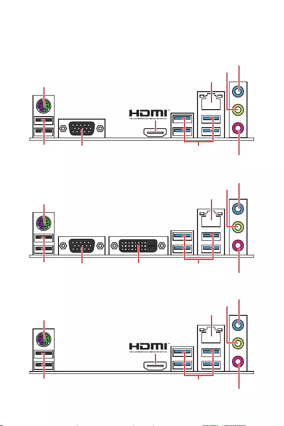
6Rückseite E/A
Rückseite E/A
PS/2 Tastatur/ Maus
B365M PRO-VH
LAN
Line-In
Mic In
Line-Out
USB 3.1 Gen1 (5Gbps)
VGA
USB 2.0
PS/2 Tastatur/ Maus
B365M WIND
LAN
Line-In
Mic In
Line-Out
USB 3.1 Gen1 (5Gbps)USB 2.0
PS/2 Tastatur/ Maus
B365M PRO-VD
LAN
Line-In
Mic In
Line-Out
USB 3.1 Gen1 (5Gbps)
VGA DVI-D
USB 2.0
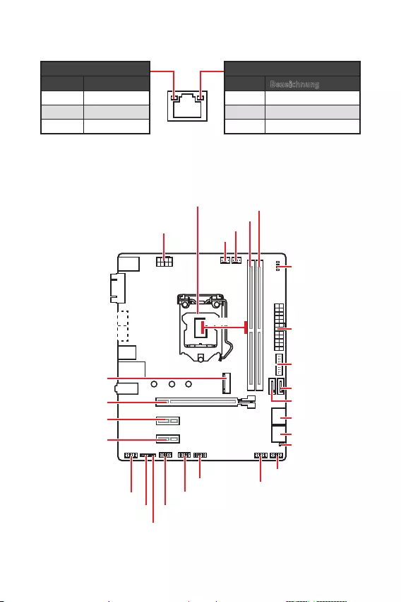
7
Rückseite E/A Übersicht der Komponenten
Verbindung/ Aktivität LED
Zustand Bezeichnung
Aus Keine Verbindung
Gelb Verbindung
Blinkt Datenaktivität
Geschwindigkeit LED
Zustand Bezeichnung
Aus 10 Mbps-Verbindung
Grün 100 Mbps-Verbindung
Orange 1 Gbps-Verbindung
LAN Port LED Zustandstabelle
Übersicht der Komponenten
CPU_FAN1
ATX_PWR1
EZ Debug LED
CPU Sockel
PCI_E1
SYS_FAN1
PCI_E2
PCI_E3
JCI1
DIMMA1
DIMMB1
SATA1
SATA2
JBAT1
JFP1
JFP2
CPU_PWR1
JUSB2
JUSB1
JTPM1
JUSB3
JCOM1
JAUD1
SATA34
SATA56
* Abstand zwischen der Mitte der CPU und dem nächsten DIMM-Steckplatz.
50,83mm*
M2_1
(B365M PRO-VD,
B365M PRO-VH)

8Übersicht der Komponenten
CPU Sockel
Installieren Sie bitte die CPU in den CPU Sockel, wie unten aufgezeigt.
Wichtig
y
Ziehen Sie das Netzkabel ab, bevor Sie die CPU ein- und ausbauen.
y
Bitte bewahren Sie die CPU Schutzkappe nach der Installation des Prozessors auf.
MSI wird RMA (Return Merchandise Authorization) Anfragen nur dann behandeln,
wenn die Schutzklappe auf dem CPU-Sockel des Motherboards sitzt.
y
Wenn Sie die CPU einbauen, denken sie bitte daran einen CPU-Kühler zu
installieren. Ein CPU-Kühlkörper ist notwendig, um eine Überhitzung zu vermeiden
und die Systemstabilität beizubehalten.
y
Stellen Sie sicher, dass Ihr Kühlkörper eine feste Verbindung mit der CPU
hergestellt hat, bevor Sie Ihr System starten.
y
Überhitzung beschädigt die CPU und das System nachhaltig. Stellen Sie stets eine
korrekte Funktionsweise des CPU Kühlers sicher, um die CPU vor Überhitzung zu
schützen. Stellen Sie sicher, dass eine gleichmäßige Schicht thermischer Paste oder
thermischen Tapes zwischen der CPU und dem Kühlkörper vorhanden ist, um die
Wärmeableitung zu erhöhen.
y
Schützen Sie den CPU-Sockel immer mit der Plastikabdeckung, wenn keine CPU
installiert ist.
y
Verwenden Sie bitte die Installationsanweisung des Kühlkörpers/Kühlers, falls Sie
eine seperate CPU oder einen Kühlkörper/ Kühler erworben haben.
1
4
6
5
78
9
3
2

9
Übersicht der Komponenten Übersicht der Komponenten
Wichtig
y
Um einen sicheren Systemstart zu gewährleisten, bestücken Sie immer DIMMA1
zuerst.
y
Aufgrund der Chipsatzressourcennutzung wird die verfügbare Kapazität des
Speichers kleiner sein als die Größe der installierten Speicherkapazität.
y
Bitte beachten Sie, dass die maximale Kapazität eines 32-Bit-Windows-
Betriebssystem bei 4GB oder weniger liegt. Wenn Sie mehr als 4 GB Speicher auf
dem Motherboard einbauen möchten, empfehlen wir deshalb, ein 64-Bit-Windows-
Betriebssystem zu installieren.
PCI_E1~3: PCIe Erweiterungssteckplätze
PCI_E1: PCIe 3.0 x16 Steckplatz (CPU Lanes)
PCI_E3: PCIe 3.0 x1 Steckplatz (PCH Lanes)
PCI_E2: PCIe 3.0 x1 Steckplatz (PCH Lanes)
Wichtig
y
Wenn Sie eine große und schwere Grafikkarte einbauen, benötigen Sie einen
Grafikkarten-Stabilisator (Graphics Card Bolster) der das Gewicht trägt und eine
Verformung des Steckplatzes vermeidet.
y
Für die Installation einer einzelnen PCIe x16 Erweiterungskarte mit optimaler
Leistung, empfehlen wir den PCI_E1 Steckplatz zu verwenden.
y
Achten Sie darauf, dass Sie den Strom abschalten und das Netzkabel aus der
Steckdose herausziehen, bevor Sie eine Erweiterungskarte installieren oder
entfernen. Lesen Sie bitte auch die Dokumentation der Erweiterungskarte, um
notwendige zusätzliche Hardware oder Software-Änderungen zu überprüfen.
DIMM-Steckplätze
Setzen Sie bitte ein Speichermodul wie untern gezeigt in den DIMM-Steckplatz ein.
123
2

10 Übersicht der Komponenten
SATA1~6: SATA 6Gb/s Anschlüsse
Diese Anschlüsse basieren auf der Hochgeschwindigkeitsschnittstelle SATA 6Gb/s.
Pro Anschluss kann ein SATA Gerät angeschlossen werden.
SATA3
SATA5
SATA4
SATA1
SATA2
SATA6
Wichtig
yDer SATA1 Anschluss wird nicht zur Verfügung stehen, wenn Sie ein M.2-SATA SSD
Modul im M.2 Steckplatz installieren
.
y
Knicken Sie das SATA-Kabel nicht in einem 90 Winkel. Datenverlust könnte die
Folge sein.
y
SATA-Kabel haben identische Stecker an beiden Enden. Es wird empfohlen den
flachen Stecker auf dem Motherboard einstecken.
JFP1, JFP2: Frontpanel-Anschlüsse
Diese Anschlüsse verbinden mit den Schaltern und LEDs auf des Frontpanels.
1
2 10
9
JFP1
1 HDD LED + 2 Power LED +
3 HDD LED — 4 Power LED —
5 Reset Switch 6 Power Switch
7 Reset Switch 8 Power Switch
9 Reserved 10 No Pin
1
JFP2
1 Speaker — 2 Buzzer +
3 Buzzer — 4 Speaker +
HDD LED
RESET SW
HDD LED HDD LED —
HDD LED +
POWER LED —
POWER LED +
POWER LED
JFP1
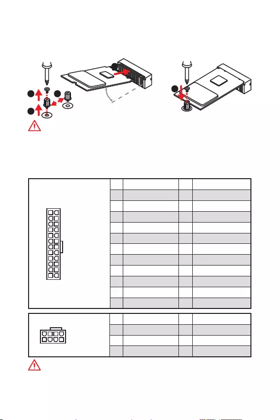
11
Übersicht der Komponenten Übersicht der Komponenten
M2_1: M.2 Steckplatz (Key M) (B365M PRO-VD, B365M PRO-VH)
Bitte installieren Sie das M.2 Solid-State-Laufwerke (SSD) in den M.2 Steckplatz
(siehe unten).
ATX_PWR1, CPU_PWR1: Stromanschlüsse
Mit diesen Anschlüssen verbinden Sie die ATX Stromstecker.
24
131
12
ATX_PWR1
1 +3.3V 13 +3.3V
2 +3.3V 14 -12V
3 Ground 15 Ground
4 +5V 16 PS-ON#
5 Ground 17 Ground
6 +5V 18 Ground
7 Ground 19 Ground
8 PWR OK 20 Res
9 5VSB 21 +5V
10 +12V 22 +5V
11 +12V 23 +5V
12 +3.3V 24 Ground
5
41
8
CPU_PWR1
1 Ground 5 +12V
2 Ground 6 +12V
3 Ground 7 +12V
4 Ground 8 +12V
Wichtig
Stellen Sie sicher, dass alle Anschlüsse mit den richtigen Anschlüssen des Netzteils
verbunden sind, um einen stabilen Betrieb der Hauptplatine sicherzustellen.
1
2
3
4
5
Wichtig
y
Intel® RST unterstützt nur PCIe M.2 SSD mit UEFI ROM.
y
Intel® Optane™ Technik wird unterstützt.
30
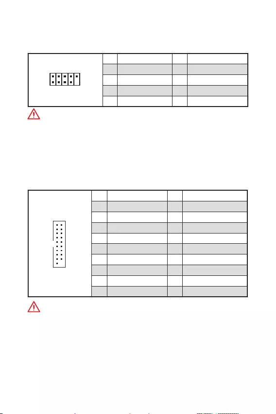
12 Übersicht der Komponenten
JUSB3: USB 3.1 Gen1 Anschluss
Mit diesem Anschluss können Sie den USB 3.1 Gen1 Anschluss auf dem Frontpanel
verbinden.
1
10 11
20
1Power 11 USB2.0+
2 USB3_RX_DN 12 USB2.0-
3 USB3_RX_DP 13 Ground
4 Ground 14 USB3_TX_C_DP
5 USB3_TX_C_DN 15 USB3_TX_C_DN
6 USB3_TX_C_DP 16 Ground
7 Ground 17 USB3_RX_DP
8 USB2.0- 18 USB3_RX_DN
9 USB2.0+ 19 Power
10 NC 20 No Pin
Wichtig
Bitte beachten Sie, dass Sie die mit Stromführende Leitung und Erdleitung
bezeichneten Pins korrekt verbinden müssen, ansonsten kann es zu Schäden
kommen.
JUSB1, JUSB2: USB 2.0 Anschlüsse
Mit diesen Anschluss können Sie die USB 2.0 Anschlüsse auf dem Frontpanel
verbinden.
1
2 10
9
1VCC 2VCC
3 USB0- 4 USB1-
5 USB0+ 6 USB1+
7 Ground 8 Ground
9 No Pin 10 NC
Wichtig
y
Bitte beachten Sie, dass Sie die mit VCC (Stromführende Leitung) und Ground
(Erdleitung) bezeichneten Pins korrekt verbinden müssen, ansonsten kann es zu
Schäden kommen.
y
Um das iPad, iPhone und den iPod über USB-Anschlüsse aufzuladen, installieren
Sie bitte die MSI® DRAGON CENTER Software.

13
Übersicht der Komponenten Übersicht der Komponenten
JAUD1: Audioanschluss des Frontpanels
Dieser Anschluss ermöglicht den Anschluss von Audiobuchsen eines Frontpanels.
1
2 10
9
1 MIC L 2 Ground
3 MIC R 4 NC
5 Head Phone R 6 MIC Detection
7 SENSE_SEND 8 No Pin
9 Head Phone L 10 Head Phone Detection
JCOM1: Serieller Anschluss
Mit diesem Anschluss können Sie das optionale serielle Schnittstelle mit dem
Einbausatze verbinden.
1
2 10
9
1 DCD 2 SIN
3 SOUT 4 DTR
5 Ground 6 DSR
7 RTS 8 CTS
9 RI 10 No Pin
EZ Debug LED
Diese LEDs zeigen den Status des Motherboards an.
CPU — CPU wird nicht erkannt oder ist fehlerhaft.
DRAM — DRAM wird nicht erkannt oder ist fehlerhaft.
VGA — GPU wird nicht erkannt oder ist fehlerhaft.
BOOT — Boot-Gerät wird nicht erkannt oder ist fehlerhaft.
JTPM1: TPM Anschluss
Dieser Anschluss wird für das TPM Modul (Trusted Platform Module) verwendet.
Weitere Informationen über den Einsatz des optionalen TPM Modules entnehmen Sie
bitte dem TPM Plattform Handbuch.
1
2 14
13
1 LPC Clock 2 3V Standby power
3 LPC Reset 4 3.3V Power
5 LPC address & data pin0 6 Serial IRQ
7 LPC address & data pin1 8 5V Power
9 LPC address & data pin2 10 No Pin
11 LPC address & data pin3 12 Ground
13 LPC Frame 14 Ground
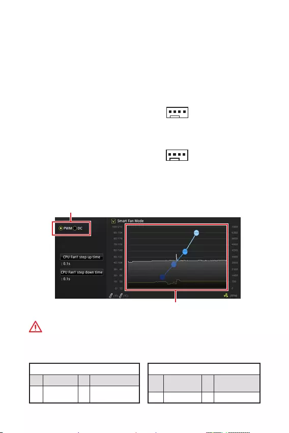
14 Übersicht der Komponenten
CPU_FAN1, SYS_FAN1: Stromanschlüsse für Lüfter
Diese Anschlüsse können im PWM (Pulse Width Modulation) Modus oder
Spannungsmodus betrieben werden. Im PWM-Modus bieten die Lüfteranschlüsse
konstante 12V Ausgang und regeln die Lüftergeschwindigkeit per
Drehzahlsteuersignal. Im DC-Modus bestimmen die Lüfteranschlüsse die
Lüftergeschwindigkeit durch Ändern der Spannung. Wenn Sie ein 3-Pin (Non-PWM)
Lüfter an einen PWM-Modus Lüfteranschluss anschließen, läuft der Lüfter mit
höchster Drehzahl und kann unangenehm laut werden. Folgen Sie den folgenden
Anweisungen, um den PWM- oder DC-Modus auszuwählen.
Pin-Belegung des PWM-Modus
1 Ground 2 +12V
3 Sense 4 Speed Control
Signal
Pin-Belegung des DC-Modus
1 Ground 2 Voltage
Control
3 Sense 4 NC
Lüfteranschlüsse des Standard-
PWM-Modus
Lüfteranschlüsse des Standard-
DC-Modus
Umschalten des Lüfter-Modus und Anpassung der Lüfterdrehzahl
Sie können unter BIOS > HARDWARE MONITOR zwischen dem PWM- und DC-Modus
umschalten und die Lüfterdrehzahl ändern.
Wählen Sie den PWM- oder DC-Modus aus
Wichtig
Überprüfen Sie die ordnungsgemäße Funktion der Lüfter nach dem Umschalten des
PWM-/ DC-Modus.
Die Gradientenpunkte des Lüfterverlaufs erlauben die
Anpasssung der Lüfterdrehzahl in Abhängigkeit von der
CPU-Temperatur.
1
CPU_FAN1
1
SYS_FAN1
Pin-Belegung der Lüfteranschlüsse

15
Übersicht der Komponenten Übersicht der Komponenten
JBAT1: Clear CMOS Steckbrücke (Reset BIOS)
Der Onboard CMOS Speicher (RAM) wird durch eine externe Spannungsversorgung
durch eine Batterie auf dem Motherboard versorgt, um die Daten der
Systemkonfiguration zu speichern. Wenn Sie die Systemkonfiguration löschen wollen,
müssen Sie die Steckbrücke für kurze Zeit umsetzen.
Daten
beibehalten
(Standardwert)
CMOS-Daten
löschen/ Reset des
BIOS
Rücksetzen des BIOS auf Standardwerte
1. Schalten Sie den Computer ab und ziehen Sie das Netzkabel ab.
2. Verwenden Sie eine Steckbrücke, um JBAT1 für 5-10 Sekunden kurzzuschließen.
3. Entfernen Sie die Steckbrücke von JBAT1.
4. Stecken Sie das Kabel Ihres Computers in die Steckdose hinein und schalten Sie
den Computer ein.
JCI1: Gehäusekontaktanschluss
Dieser Anschluss wird mit einem Kontaktschalter verbunden.
Normal
(Standardwert)
Löse den Gehäuseeingriff
aus
Gehäusekontakt-Detektor verwenden
1. Schließen Sie den JCI1-Anschluss am Gehäusekontakt-Schalter/ Sensor am
Gehäuse an.
2. Schließen Sie die Gehäuseabdeckung.
3. Gehen Sie zu BIOS > Security > Chassis Intrusion Configuration.
4. Stellen Sie Chassis Intrusion auf Enabled.
5. Drücken Sie F10 zum Speichern und Beenden und drücken Sie dann die Enter—
Taste, um Ja auszuwählen.
6. Bei eingeschaltetem Computer wird eine Warnmeldung auf dem Bildschirm
angezeigt, wenn die Gehäuseabdeckung wieder geöffnet wird.
Gehäusekontakt-Warnung zurücksetzen
1. Gehen Sie zu BIOS > Security > Chassis Intrusion Configuration.
2. Stellen Sie Chassis Intrusion auf Reset.
3. Drücken Sie F10 zum Speichern und Beenden und drücken Sie dann die Enter—
Taste, um Ja auszuwählen.

16 BIOS-Setup
BIOS-Setup
Die Standardeinstellungen bieten die optimale Leistung für die Systemstabilität unter
Normalbedingungen. Sie sollten immer die Standardeinstellungen behalten, um
mögliche Schäden des Systems oder Boot-Fehler zu vermeiden, außer Sie besitzen
ausreichende BIOS Kenntnisse.
Wichtig
y
BIOS Funktionen werden für eine bessere Systemleistung kontinuierlich
aktualisiert. Deswegen können die Beschreibungen leicht von der letzten Fassung
des BIOS abweichen und sollten demnach nur als Anhaltspunkte dienen. Für eine
Beschreibung der BIOS Funktionen rufen Sie die HELP Informationstafel aus.
y
Die Bilder .in diesem Kapitel stellen lediglich Referenzen dar und können von dem
von Ihnen erworbenen Produkt abweichen.
Öffnen des BIOS Setups
Befolgen Sie bitte die nachfolgende Schritte, um das BIOS Setup aufzurufen.
yWährend des BOOT-Vorgangs drücken Sie die Taste ENTF, wenn die Meldung Press
DEL key to enter Setup Menu, F11 to enter Boot Menu erscheint.
yVerwenden Sie die MSI DRAGON CENTER Anwendung. Klicken Sie die GO2BIOS—
Taste und drücken OK. Das System startet neu und geht direkt ins BIOS.
Funktionstasten
F1: Allgemeine Hilfe
F2: Hinzufügen/Entfernen eines Favoritenpunkts
F3: Öffnen des Favoriten Menüs
F4: Öffnen des Menüs CPU-Spezifikationen
F5: Öffnen des Memory-Z Menüs
F6: Laden der ursprünglichen Setup-Standardwerte
F7: Wechselt zwischen dem Erweiterten-Modus und EZ-Modus
F8: OC-Profil wird vom USB-Stick geladen
F9: OC-Profil wird auf einem USB-Stick gespeichert
F10: Speichern oder Zurücksetzen der Änderungen*
F12: Macht einen Screenshot und speichert auf einen FAT/FAT32-USB-Laufwerk.
Strg+F: Öffnet die Suchseite
* Beim Drücken der F10 Taste wird das Fenster zum Speichern der Einstellungen
angezeigt. Wählen Sie Yes, um die Wahl zu bestätigen, oder No, um die derzeitige
Einstellung beizubehalten.

17
BIOS-Setup BIOS-Setup
Reset des BIOS
Sie können die Werkseinstellung wieder herstellen, um bestimmte Probleme zu
lösen. Es gibt verschiedene Möglichkeiten, um das BIOS zurückzusetzen:
yÖffnen Sie das BIOS und drücken Sie F6, um optimierten Einstellungen zu laden.
ySchließen Sie die Clear CMOS Steckbrücke an das Motherboard an.
Wichtig
Stellen Sie sicher, dass Ihr Computer ausgeschaltet ist, bevor Sie die CMOS-Daten
löschen. Bitte lesen Sie für Informationen zum BIOS-Reset im Bereich „Clear CMOS
Steckbrücke nach.
Aktualisierung des BIOS
Aktualisierung des BIOS mit dem M-FLASH-Programm
Vorbereitung:
Laden Sie bitte die neueste BIOS Version, die dem Motherboard-Modell entspricht,
von der offiziellen MSI Website herunter und speichern Sie die BIOS-Datei auf USB-
Flash-Laufwerk.
BIOS-Aktualisierungsschritte:
1. Drücken Sie während des POST-Vorgangs die Taste (Entf), um das BIOS zu öffnen.
2. Schließen das USB-Flashlaufwerk mit der BIOS-Datei an den Computer.
3. Wählen Sie die Registerkarte M-FLASH und klicken Sie auf Yes (Ja), um das
System neu zu starten. Rufen Sie den Flash-Modus auf.
4. Wählen Sie die BIOS-Datei zur Durchführung des BIOS-Aktualisierungsprozesses
aus.
5. Nachdem das Flashen des BIOS vollständig ist, startet das System automatisch
neu.
Aktualisierung des BIOS mit MSI DRAGON CENTER
Vorbereitung:
Stellen Sie sicher, dass zuvor die LAN-Treiber installiert wurden und eine
Internetverbindung eingerichtet ist.
BIOS-Aktualisierungsschritte:
1. Installieren und starten Sie „MSI DRAGON CENTER.
2. Wählen Sie BIOS Update aus.
3. Klicken Sie auf die Scan Taste.
4. Klicken Sie auf dieses Download-Icon, um die neueste BIOS-Datei zu laden und
zu installieren.
5. Klicken Sie auf Next (Weiter) und wählen Sie In Windows Mode aus. Und klicken
dann auf Next (Weiter) und Start (Starten), um das BIOS-Update zu starten.
6. Nachdem das Flashen des BIOS vollständig ist, startet das System automatisch
neu.

18 Installation von OS, Treibern und Utilities
Installation von OS, Treibern und Utilities
Laden Sie die neuesten Treiber und Dienstprogramme von www.msi.com herunter
und aktualisieren Sie sie.
Installation von Windows® 10
1. Schalten Sie den Computer ein.
2. Legen Sie die Windows® 10 Disk oder das USB-Flashlaufwerk in das optisches
Laufwerk.
3. Drücken Sie die Taste Restart auf dem Computergehäuse.
4. Drücken Sie die F11-Taste während des POST-Vorgangs (Power-On Self Test), um
das Bootmenu zu öffnen.
5. Wählen Sie die Windows® 10 Disk oder das USB-Flashlaufwerk aus dem
Bootmenu.
6. Wenn eine entsprechende Meldung Press any key to boot from CD or DVD…
angezeigt wird, drücken Sie eine beliebige Taste.
7. Folgen Sie den Anweisungen auf dem Bildschirm, um das Dienstprogramm
„Windows® 10 zu installieren.
Installation von Treibern
1. Starten Sie Ihren Computer mit Windows® 10.
2. Legen Sie die MSI® Treiber Disk in das optisches Laufwerk.
3. Klicken Sie auf die Pop-up-Meldung Wählen Sie eine Aktion für
Wechseldatenträger aus und wählen Sie DVD Setup.exe starten aus, aus, um
den Installer zu öffnen. Wenn Sie die AutoPlay-Funktionen in der Windows-
Systemsteuerung ausschalten, können Sie das Programm DVDSetup.exe im
Hauptverzeichnis der MSI Treiber CD auch manuell ausführen.
4. Der Installer wird findet eine Liste aller benötigten Treiber auf der Treiber/
Software-Registerkarte.
5. Klicken Sie auf Install in der rechten unteren Ecke des Fensters.
6. Die Treiber-Installation läuft. Wenn die Installation abgeschlossen ist, werden Sie
dazu aufgefordet, den Computer neu zu starten.
7. Klicken Sie auf OK zum Beenden.
8. Starten Sie Ihren Computer neu.

19
Installation von OS, Treibern und Utilities Installation von OS, Treibern und Utilities
Installation von Utilities
Bevor Sie Anwendungen installieren, müssen Sie die Treiber-Installation vollständig
beendet haben.
1. Öffnen Sie den Installer wie beschrieben.
2. Klicken Sie auf Utilities.
3. Wählen Sie die Dienstprogramme, die installiert werden soll.
4. Klicken Sie die Taste Install in der rechten unteren Ecke des Fensters.
5. Die Utilities-Installation ist im Gange. Wenn die Installation abgeschlossen ist,
werden Sie dazu aufgefordet, den Computer neu zu starten.
6. Klicken Sie zum Beenden auf OK.
7. Starten Sie Ihren Computer neu.

20 Installation von OS, Treibern und Utilities

1
< 1>
…………………………………………2
………………………………………………………… 3
/ …………………………………………..6
B365M PRO-VH ………………………………………………………………………………………6
B365M PRO-VD ………………………………………………………………………………………6
B365M WIND ………………………………………………………………………………………….6
LAN ………………………………………..7
…………………………………………………..7
……………………………………………………………………………8
DIMM ………………………………………………………………………………………….9
PCI_E1~3: PCIe ………………………………………………………9
JFP1, JFP2: ……………………………………………..10
SATA1~6: SATA 6 / ……………………………………………………………. 10
M2_1: M.2 ( M) (B365M PRO-VD, B365M PRO-VH) ……………….11
ATX_PWR1, CPU_PWR1: ……………………………..11
JUSB1, JUSB2: USB 2.0 ………………………………………………………….12
JUSB3: USB 3.1 Gen1 ……………………………………………………………….12
JAUD1: …………………………………………….13
JCOM1: …………………………………………13
JTPM1: TPM ………………………………………………………………..13
EZ …………………………………………………………………….13
CPU_FAN1, SYS_FAN1: …………………………………..14
JCI1: …………………………………………..15
JBAT1: CMOS ( BIOS) ………………………..15
BIOS ………………………………………………………………………………16
BIOS ……………………………………………………………………….16
BIOS ………………………………………………………………………………………….17
BIOS ……………………………………………………………………………….17
, ……………………………………………… 18
Windows® 10 ……………………………………………………………………….18
………………………………………………………………………..18
……………………………………………………………………………….18
MSI®
B365M PRO-VD/ B365M PRO-VH/ B365M WIND.
, ,
BIOS
.

2
y,
. ,
, .
y,
.
, .
y
.
y
. , ,
,
.
y , ,
.
y ,
.
y , .
, .
y , ,
.
y
.
y .
y .
y
,
, .
y , .
.
y ,
.
y
:
.
.
.
.
.
y 60 C (140
F), .

3
Intel® Core™ 9-/8-
/ Pentium® Gold / Celeron®
LGA 1151
* , www.msi.com
.
Intel® B365
y2x DDR4 32
y DDR4 2666/ 2400/ 2133
y
y non-ECC,
y Intel® Extreme Memory Profile (XMP)
* , www.msi.com
.
y1x PCIe 3.0 x16
y2x PCIe 3.0 x1
y1x VGA,
2048×1536@50, 2048×1280@60,
1920×1200@60 (B365M PRO-VD, B365M PRO-VH)
y1x DVI-D,
1920×1200@60 (B365M PRO-VD)
y1x HDMI™ 1.4,
4096×2160@30 (B365M PRO-VH, B365M
WIND)
*
«F».
Intel® B365
y6x SATA 6/*
y1x M.2 ( M) (B365M PRO-VD, B365M PRO-VH)
PCIe 3.0 x4 SATA 6/
2242/ 2260/ 2280
Intel® Optane™ **
* SATA1
M.2 SATA SSD M.2.
** Intel®
Optane™ , BIOS
— MSI.

4
USB
Intel® B365
y6x USB 3.1 Gen1 (SuperSpeed USB) (4
Type-A , 2
USB)
y6x USB 2.0 (High-speed USB) (2
, 4
USB)
yRealtek® ALC887 Codec
y7.1- High Definition Audio
LAN 1x Realtek RTL8111H
y1x PS/2
y2x USB 2.0
y1x VGA (B365M PRO-VD, B365M PRO-VH)
y1x DVI-D (B365M PRO-VD)
y1x HDMI™ (B365M PRO-VH, B365M WIND)
y4x USB 3.1 Gen1 Type-A
y1x LAN (RJ45)
y3x
y1x 24- ATX
y1x 8- ATX 12
y1x USB 3.1 Gen1 ( 2-
USB 3.1 Gen1)
y6x SATA 6/
y1x CMOS
y2x
y1x
y1x
y2x USB 2.0 ( 4-
USB 2.0)
y1x
y1x 4-
y1x 4-
y1x TPM
— NUVOTON NCT5567
5
y /
y /
y /
— ym-ATX —
y8.9 x 7.3 (22.6 x 18.5 )
BIOS
y1x 128
yUEFI AMI BIOS
yACPI 6.1 , SM BIOS 2.8
y
y
yDRAGON CENTER
yCPU-Z MSI GAMING
yIntel® Extreme Tuning Utility
yGoogle Chrome™, Google Toolbar, Google Drive
yNorton™ Internet Security Solution
Dragon Center
yHardware Monitor
yEyerest
yLive Update
http://download.msi.com/manual/
mb/DRAGONCENTER2.pdf.
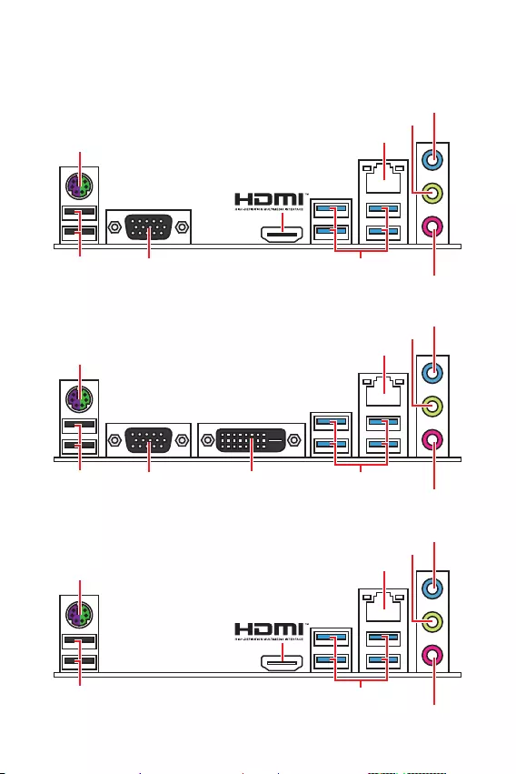
6 /
/
PS/2 /
B365M WIND
LAN
USB 3.1 Gen1 (5/)USB 2.0
PS/2 /
B365M PRO-VH
LAN
USB 3.1 Gen1 (5/)
VGA
USB 2.0
PS/2 /
B365M PRO-VD
LAN
USB 3.1 Gen1 (5/)
VGA DVI-D
USB 2.0
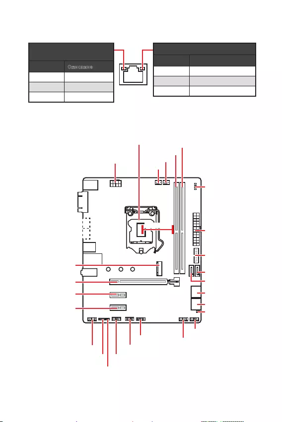
7
/
LAN
CPU_FAN1
ATX_PWR1
EZ Debug LED
PCI_E1
SYS_FAN1
PCI_E2
PCI_E3
JCI1
DIMMA1
DIMMB1
SATA1
SATA2
JBAT1
JFP1
JFP2
CPU_PWR1
JUSB2
JUSB1
JTPM1
JUSB3
JCOM1
JAUD1
SATA34
SATA56
* DIMM.
50.83*
/
.
. 10 /
100 /
1 /
M2_1
(B365M PRO-VD,
B365M PRO-VH)

8
, ,
.
!
y
,
.
y
,
. ,
, MSI ,
.
y
. , ,
.
y
.
y
.
.
( )
.
y
,
.
y
,
. .
1
4
6
5
78
9
3
2
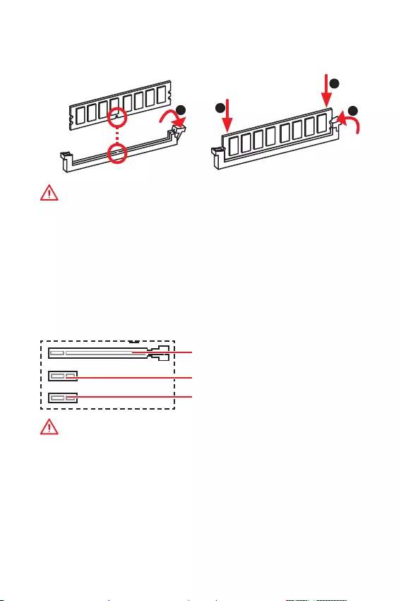
9
!
y
DIMMA1.
y
,
, .
y
, ,
32- Windows, 4 .
4
, 64- Windows.
PCI_E1~3: PCIe
PCI_E1: PCIe 3.0 x16 ( CPU)
PCI_E3: PCIe 3.0 x1 ( PCH)
PCI_E2: PCIe 3.0 x1 ( PCH)
!
y
,
, MSI Gaming Series Graphics Card Bolster
.
y
PCIe x16
PCI_E1.
y
,
.
.
DIMM
, DIMM, .
123
2
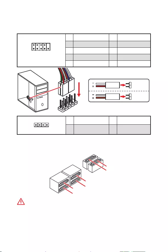
10
SATA1~6: SATA 6 /
SATA 6 /.
SATA.
SATA3
SATA5
SATA4
SATA1
SATA2
SATA6
!
y
SATA1 M.2 SATA SSD
M.2.
y
SATA . ,
.
y
SATA .
,
.
JFP1, JFP2:
, .
1
2 10
9
JFP1
1 HDD LED + 2 Power LED +
3 HDD LED — 4 Power LED —
5 Reset Switch 6 Power Switch
7 Reset Switch 8 Power Switch
9 Reserved 10 No Pin
1
JFP2
1 Speaker — 2 Buzzer +
3 Buzzer — 4 Speaker +
HDD LED
RESET SW
HDD LED HDD LED —
HDD LED +
POWER LED —
POWER LED +
POWER LED
JFP1
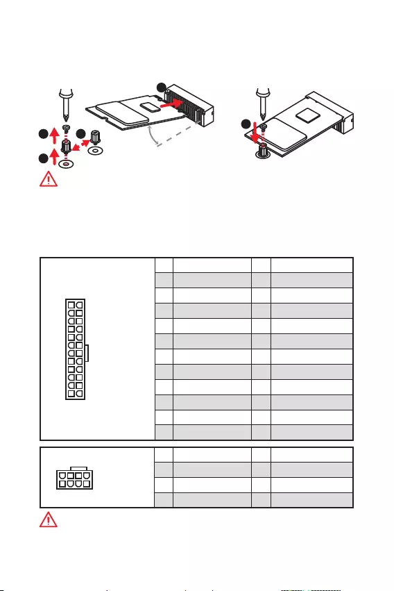
11
M2_1: M.2 ( M) (B365M PRO-VD, B365M PRO-VH)
, (SSD) M.2 M.2,
.
ATX_PWR1, CPU_PWR1:
ATX.
24
131
12
ATX_PWR1
1 +3.3V 13 +3.3V
2 +3.3V 14 -12V
3 Ground 15 Ground
4 +5V 16 PS-ON#
5 Ground 17 Ground
6 +5V 18 Ground
7 Ground 19 Ground
8 PWR OK 20 Res
9 5VSB 21 +5V
10 +12V 22 +5V
11 +12V 23 +5V
12 +3.3V 24 Ground
5
41
8
CPU_PWR1
1 Ground 5 +12V
2 Ground 6 +12V
3 Ground 7 +12V
4 Ground 8 +12V
!
.
1
2
3
4
5
!
y
Intel® RST PCIe M.2 SSD UEFI ROM.
y
Intel® Optane™.
30
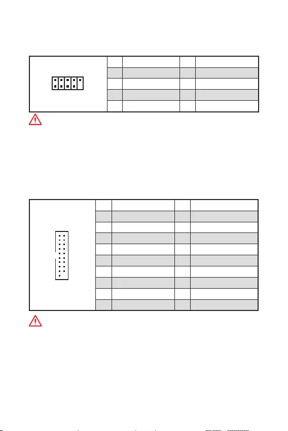
12
JUSB3: USB 3.1 Gen1
USB 3.1 Gen1
.
1
10 11
20
1Power 11 USB2.0+
2 USB3_RX_DN 12 USB2.0-
3 USB3_RX_DP 13 Ground
4 Ground 14 USB3_TX_C_DP
5 USB3_TX_C_DN 15 USB3_TX_C_DN
6 USB3_TX_C_DP 16 Ground
7 Ground 17 USB3_RX_DP
8 USB2.0- 18 USB3_RX_DN
9 USB2.0+ 19 Power
10 NC 20 No Pin
!
, ,
.
JUSB1, JUSB2: USB 2.0
USB 2.0
.
1
2 10
9
1VCC 2VCC
3 USB0- 4 USB1-
5 USB0+ 6 USB1+
7 Ground 8 Ground
9 No Pin 10 NC
!
y
, ,
VCC .
y
, iPad, iPhone iPod USB,
, MSI® DRAGON CENTER.
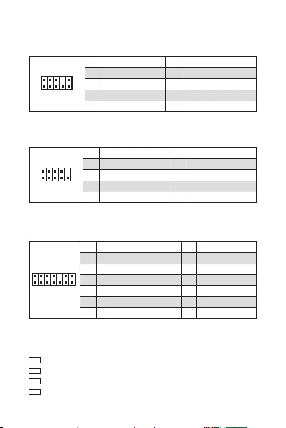
13
JAUD1:
.
1
2 10
9
1 MIC L 2 Ground
3 MIC R 4 NC
5 Head Phone R 6 MIC Detection
7 SENSE_SEND 8 No Pin
9 Head Phone L 10 Head Phone Detection
JCOM1:
,
.
1
2 10
9
1 DCD 2 SIN
3 SOUT 4 DTR
5 Ground 6 DSR
7 RTS 8 CTS
9 RI 10 No Pin
EZ
.
JTPM1: TPM
(Trusted Platform
Module). . .
1
2 14
13
1 LPC Clock 2 3V Standby power
3 LPC Reset 4 3.3V Power
5 LPC address & data pin0 6 Serial IRQ
7 LPC address & data pin1 8 5V Power
9 LPC address & data pin2 10 No Pin
11 LPC address & data pin3 12 Ground
13 LPC Frame 14 Ground
CPU — .
DRAM — DRAM .
VGA — .
BOOT — .
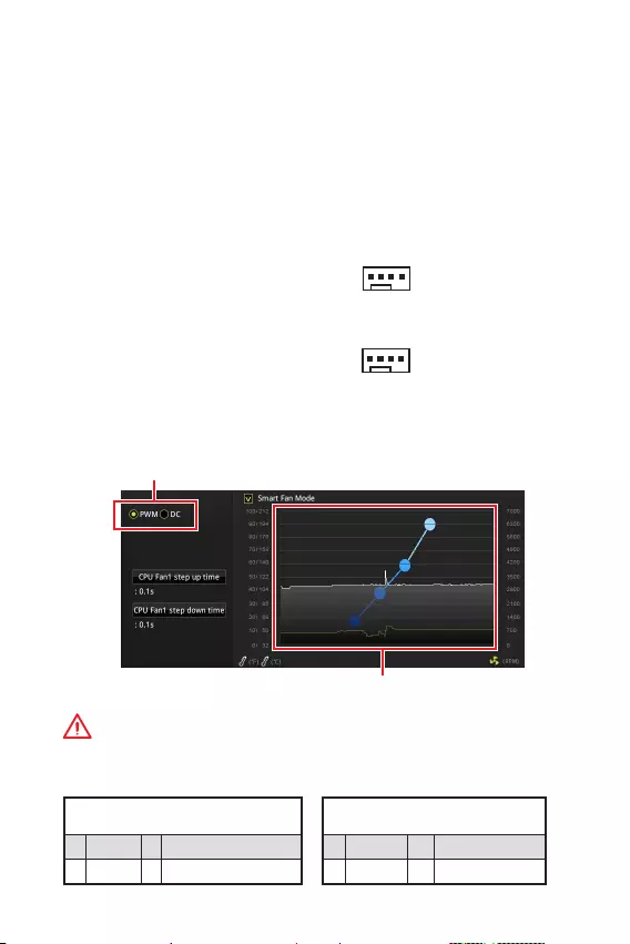
14
CPU_FAN1, SYS_FAN1:
: PWM (PulseWidth
Modulation) .
PWM
12,
.
,
. ,
3- (Non-PWM)
PWM, .
.
, PWM DC, .
PWM
DC
BIOS > HARDWARE MONITOR
: PWM DC, .
PWM DC
!
, PWM/ DC.
.
1
CPU_FAN1
1
SYS_FAN1
PWM
1 Ground 2 +12V
3 Sense 4 Speed Control Signal
DC
1 Ground 2 Voltage Control
3 Sense 4 NC

15
JBAT1: CMOS (
BIOS)
CMOS
.
( CMOS ), .
( ) /
BIOS
BIOS
1. .
2. , JBAT1
5-10 .
3. JBAT1.
4. .
JCI1:
.
( )
1. JCI1.
2. .
3. BIOS > Security > Chassis Intrusion Configuration.
4. Chassis Intrusion Enabled.
5. F10, ,
Enter, Yes.
6.
.
1. BIOS > Security > Chassis Intrusion Configuration.
2. Chassis Intrusion, Reset.
3. F10, ,
Enter, Yes.

16 BIOS
BIOS
.
BIOS, .
,
.
!
y
, BIOS
.
BIOS .
BIOS,
HELP.
y
.
BIOS
BIOS.
y Delete, Press
DEL key to enter Setup Menu, F11 to enter Boot Menu .
y MSI DRAGON CENTER.
GO2BIOS .
BIOS.
F1:
F2: /
F3:
F4:
F5: Memory-Z
F6:
F7: EZ
F8:
F9:
F10: *
F12: USB — ( FAT /
FAT32 ).
Ctrl+F:
* F10 . Yes
No, .

17
BIOS BIOS
BIOS
BIOS .
:
y BIOS F6
.
y Clear CMOS .
!
, CMOS.
BIOS,
CMOS.
BIOS
BIOS M-FLASH
:
, BIOS MSI,
. BIOS
— USB.
BIOS:
1. Del BIOS
POST.
2. — USB, .
3. M-FLASH Yes
.
4. BIOS BIOS.
5. ,
.
BIOS MSI DRAGON CENTER
:
,
.
BIOS:
1. MSI DRAGON CENTER.
2. BIOS Update.
3. Scan.
4. Download,
BIOS.
5. Next In Windows mode.
Next Start BIOS.
6. ,
.

18 ,
,
C : www.msi.com.
Windows® 10
1. .
2. Windows® 10
USB USB —,
Windows® 10.
3. Restart .
4. F11 POST (Power-On Self Test) ,
.
5. / USB — .
6. , Press
any key to boot from CD or DVD…
7. , Windows® 10.
1. Windows® 10.
2. MSI® Driver Disc
.
3. Select to choose what happens with this disc
Run DVDSetup.exe, .
Windows ,
DVDSetup.exe
MSI Driver Disc.
4.
Drivers/Software.
5. Install .
6. .
.
7. OK .
8. .
.
1. , .
2. Utilities.
3. .
4. Install .
5. .
.
6. OK .
7. .

1
< 1>
……………………………………………………………………………………………..2
…………………………………………………………………………………………………… 3
I/O ………………………………………………………………………………………. 6
B365M PRO-VH ………………………………………………………………………………………6
B365M PRO-VD ………………………………………………………………………………………6
B365M WIND ………………………………………………………………………………………….6
LAN LED ……………………………………………………………………………..7
……………………………………………………………………………………………..7
CPU ……………………………………………………………………………………………….8
DIMM ……………………………………………………………………………………………..9
PCI_E1~3: PCIe ………………………………………………………………………..9
JFP1, JFP2: ……………………………………………………………………..10
SATA1~6: SATA 6Gb/s …………………………………………………………………….10
M2_1: M.2 (M ) (B365M PRO-VD, B365M PRO-VH)………………………….11
ATX_PWR1, CPU_PWR1: …………………………………………………………. 11
JUSB1, JUSB2: USB 2.0 …………………………………………………………………12
JUSB3: USB 3.1 Gen1 …………………………………………………………………….12
JAUD1: ……………………………………………………………………………13
JCOM1: ……………………………………………………………………………13
JTPM1: TPM …………………………………………………………………………..13
LED …………………………………………………………………………………..13
CPU_FAN1, SYS_FAN1: ……………………………………………………………14
JCI1: …………………………………………………………………………15
JBAT1: CMOS ( BIOS) ……………………………………………………….15
BIOS ………………………………………………………………………………………….16
BIOS ……………………………………………………………………………………..16
BIOS …………………………………………………………………………………………….17
BIOS …………………………………………………………………………………………….17
…………………………………………………….18
Windows® 10………………………………………………………………………………..18
………………………………………………………………………………………………18
………………………………………………………………………………………………18
MSI® B365M PRO-VD/ B365M PRO-VH/ B365M
WIND BIOS

2
y(ESD)
y
y
y(ESD) ESD
y
y
y
y
y
y
y
y
y
y
y
y60(140)

3
CPU
LGA1151 / Intel® Core™ / Pentium®
Gold / Celeron®
* www.intel.com
Intel® B365
y2 DDR4 32GB
y DDR4 2666/ 2400/ 2133 MHz
y
y -ECC —
y Intel® (XMP)
* www.msi.com
y1 PCIe 3.0 x16
y2 PCIe 3.0 x1
y1 VGA 2048×1536@50Hz,
2048×1280@60Hz, 1920×1200@60Hz (B365M PRO-VD, B365M
PRO-VH)
y1 DVI-D 1920×1200@60Hz
(B365M PRO-VD)
y1 HDMI™ 1.4 4096×2160@30Hz
(B365M PRO-VH, B365M WIND)
* F
Intel® B365
y6 SATA 6Gb/s *
y1 M.2 (M ) (B365M PRO-VD, B365M PRO-VH)
PCIe 3.0 x4 SATA 6Gb/s
2242/ 2260/ 2280
® (Optane)™ **
* M.2 M.2 SATA SATA1
** ® (Optane)™ MSI
BIOS

4
USB
Intel® B365
y6 USB 3.1 Gen1 (SuperSpeed USB) (4 Type-A
USB 2 )
y6 USB 2.0 (High-speed USB) (2
USB 4 )
yRealtek® ALC887
y7.1-
LAN 1 Realtek RTL8111H
y1 PS/2 /
y2 USB 2.0
y1 VGA (B365M PRO-VD, B365M PRO-VH)
y1 DVI-D (B365M PRO-VD)
y1 HDMI™ (B365M PRO-VH, B365M WIND)
y4 USB 3.1 Gen1 Type-A
y1 LAN (RJ45)
y3
y1 24-pin ATX
y1 8-pin ATX 12V
y1 USB 3.1 Gen1 ( 2 USB 3.1 Gen1 )
y6 SATA 6Gb/s
y1 CMOS
y2
y1
y1
y2 USB 2.0 ( 4 USB 2.0 )
y1
y1 4-pin CPU
y1 4-pin
y1 TPM
I/O NUVOTON NCT5567
yCPU/
yCPU/
yCPU/
5
ym-ATX
y8.9 x 7.3 (22.6 x 18.5 )
BIOS
y1 128 Mb flash
yUEFI AMI BIOS
yACPI 6.1 , SM BIOS 2.8
y
y
yDRAGON CENTER
yMSI GAMING CPU-Z
y®
yGoogle ™Google Google
y™
Dragon Center
y
yEyerest
yLive Update
, http://
download.msi.com/manual/mb/
DRAGONCENTER2.pdf
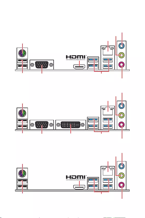
6 I/O
I/O
PS/2 /
B365M PRO-VH
LAN
USB 3.1 Gen1 (5Gbps)
VGA
USB 2.0
PS/2 /
B365M WIND
LAN
USB 3.1 Gen1 (5Gbps)USB 2.0
PS/2 /
B365M PRO-VD
LAN
USB 3.1 Gen1 (5Gbps)
VGA DVI-D
USB 2.0
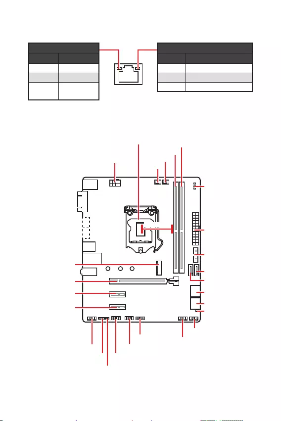
7
I/O
/
10 Mbps
100 Mbps
1 Gbps
LAN LED
CPU_FAN1
ATX_PWR1
LED
CPU
PCI_E1
SYS_FAN1
PCI_E2
PCI_E3
JCI1
DIMMA1
DIMMB1
SATA1
SATA2
JBAT1
JFP1
JFP2
CPU_PWR1
JUSB2
JUSB1
JTPM1
JUSB3
JCOM1
JAUD1
SATA34
SATA56
* CPU DIMM
50.83*
M2_1
(B365M PRO-VD,
B365M PRO-VH)

8
CPU
CPU CPU
y
CPU
y
CPU (RMA)
CPU
y
CPU CPU CPU
y
CPU CPU
y
CPU
CPU CPU (
)
y
CPU CPU
y
CPU / /
1
4
6
5
78
9
3
2
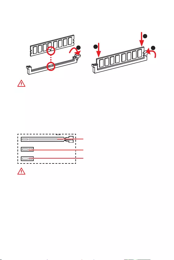
9
y
, DIMMA1
y
y
32 Windows
4GB 4GB 64
Windows
PCI_E1~3: PCIe
PCI_E1: PCIe 3.0 x16 (CPU )
PCI_E3: PCIe 3.0 x1 (PCH )
PCI_E2: PCIe 3.0 x1 (PCH )
y
MSI
y
PCIe x16 PCI_E1
y
DIMM
DIMM
123
2
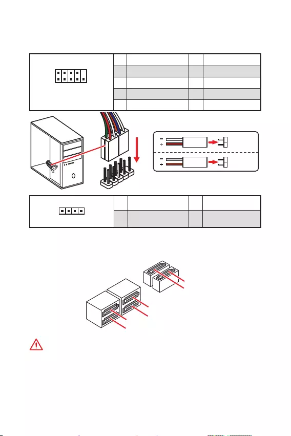
10
SATA1~6: SATA 6Gb/s
SATA 6Gb/s SATA
SATA3
SATA5
SATA4
SATA1
SATA2
SATA6
y
M.2 M.2 SATA SATA1
y
SATA 90
y
SATA
JFP1, JFP2:
LED
1
2 10
9
JFP1
1 HDD LED + 2 Power LED +
3 HDD LED — 4 Power LED —
5 Reset Switch 6 Power Switch
7 Reset Switch 8 Power Switch
9 Reserved 10 No Pin
1
JFP2
1 Speaker — 2 Buzzer +
3 Buzzer — 4 Speaker +
HDD LED
RESET SW
HDD LED HDD LED —
HDD LED +
POWER LED —
POWER LED +
POWER LED
JFP1

11
M2_1: M.2 (M ) (B365M PRO-VD, B365M PRO-VH)
M.2 (SSD) M.2
ATX_PWR1, CPU_PWR1:
ATX
24
131
12
ATX_PWR1
1 +3.3V 13 +3.3V
2 +3.3V 14 -12V
3 Ground 15 Ground
4 +5V 16 PS-ON#
5 Ground 17 Ground
6 +5V 18 Ground
7 Ground 19 Ground
8 PWR OK 20 Res
9 5VSB 21 +5V
10 +12V 22 +5V
11 +12V 23 +5V
12 +3.3V 24 Ground
5
41
8
CPU_PWR1
1 Ground 5 +12V
2 Ground 6 +12V
3 Ground 7 +12V
4 Ground 8 +12V
ATX
1
2
3
4
5
y
Intel® RST UEFI ROM PCIe M.2
y
® (Optane)™
30

12
JUSB3: USB 3.1 Gen1
USB 3.1 Gen1
1
10 11
20
1Power 11 USB2.0+
2 USB3_RX_DN 12 USB2.0-
3 USB3_RX_DP 13 Ground
4 Ground 14 USB3_TX_C_DP
5 USB3_TX_C_DN 15 USB3_TX_C_DN
6 USB3_TX_C_DP 16 Ground
7 Ground 17 USB3_RX_DP
8 USB2.0- 18 USB3_RX_DN
9 USB2.0+ 19 Power
10 NC 20 No Pin
JUSB1, JUSB2: USB 2.0
USB 2.0
1
2 10
9
1VCC 2VCC
3 USB0- 4 USB1-
5 USB0+ 6 USB1+
7 Ground 8 Ground
9 No Pin 10 NC
y
VCC
y
iPadiPhone iPod USB MSI® DRAGON
CENTER

13
JAUD1:
1
2 10
9
1 MIC L 2 Ground
3 MIC R 4 NC
5 Head Phone R 6 MIC Detection
7 SENSE_SEND 8 No Pin
9 Head Phone L 10 Head Phone Detection
JCOM1:
1
2 10
9
1 DCD 2 SIN
3 SOUT 4 DTR
5 Ground 6 DSR
7 RTS 8 CTS
9 RI 10 No Pin
LED
LED
CPU — CPU
DRAM — DRAM
VGA — GPU
BOOT —
JTPM1: TPM
TPM () TPM
1
2 14
13
1 LPC Clock 2 3V Standby power
3 LPC Reset 4 3.3V Power
5 LPC address & data pin0 6 Serial IRQ
7 LPC address & data pin1 8 5V Power
9 LPC address & data pin2 10 No Pin
11 LPC address & data pin3 12 Ground
13 LPC Frame 14 Ground
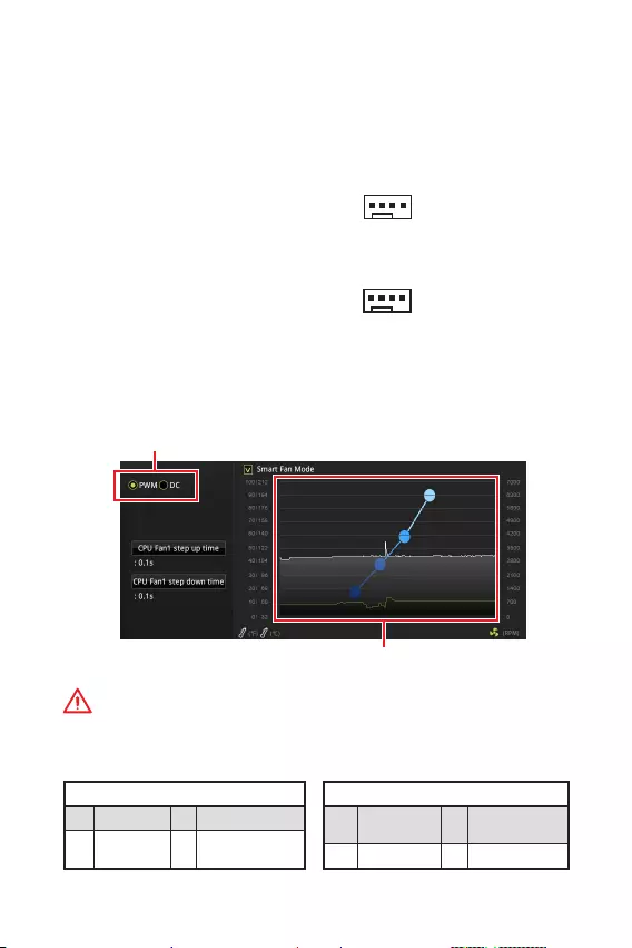
14
CPU_FAN1, SYS_FAN1:
PWM () DC PWM
12V DC
3 (-PWM) PWM
100% PWM
DC
PWM
1 Ground 2 +12V
3 Sense 4 Speed Control
Signal
DC
1 Ground 2 Voltage
Control
3 Sense 4 NC
PWM
DC
PWM DC BIOS > HARDWARE MONITOR
PWM DC
PWM/ DC
CPU
1
CPU_FAN1
1
SYS_FAN1
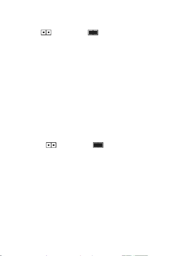
15
JBAT1: CMOS ( BIOS)
CMOS
CMOS
() CMOS/
BIOS
BIOS
1.
2. JBAT1 5-10
3. JBAT1
4.
JCI1:
()
1. JCI1 /
2.
3. BIOS > Security > Chassis Intrusion Configuration
4. Chassis Intrusion Enabled
5. F10 Enter Yes
6.
1. BIOS > Security > Chassis Intrusion Configuration
2. Chassis Intrusion Reset
3. F10 Enter Yes

16 BIOS
BIOS
BIOS
y
BIOS
BIOS
y
BIOS
BIOS
y Press DEL key to enter Setup Menu, F11 to enter
Boot Menu Delete
y MSI DRAGON CENTER GO2BIOS OK
BIOS
F1:
F2: /
F3: Favorites
F4: CPU
F5: Memory-Z
F6:
F7: EZ
F8:
F9:
F10: *
F12: U (FAT/ FAT32
Ctrl+F:
* F10 Yes
No

17
BIOS BIOS
BIOS
BIOS BIOS
y BIOS F6
y CMOS
CMOS CMOS
BIOS
BIOS
M-FLASH BIOS
MSI BIOS BIOS U
BIOS
1. POST Del BIOS
2. U
3. M-FLASH Yes flash
4. BIOS BIOS
5. 100%
MSI DRAGON CENTER BIOS
LAN
BIOS
1. MSI DRAGON CENTER
2. BIOS Update
3. Scan
4. Download BIOS
5. Next In Windows mode Next Start BIOS
6. 100%

18
www.msi.com
Windows® 10
1.
2. Windows® 10 / USB
3. Restart
4. POST () F11
5. Windows® 10 /USB
6. Press any key to boot from CD or DVD…
7. Windows® 10
1. Windows® 10
2. MSI®
3. Select to choose what happens with this disc Run
DVDSetup.exe Windows AutoPlay
MSI DVDSetup.exe
4. Drivers/Software
5. Install
6.
7. OK
8.
1.
2. Utilities
3.
4. Install
5.
6. OK
7.

1
< 1>
……………………………………………………………………………………………..2
…………………………………………………………………………………………………… 3
I/O ………………………………………………………………………………………………6
B365M PRO-VH ………………………………………………………………………………………6
B365M PRO-VD ………………………………………………………………………………………6
B365M WIND ………………………………………………………………………………………….6
LED ………………………………………………………………………..7
……………………………………………………………………………………………..7
CPU ……………………………………………………………………………………………….8
…………………………………………………………………………………………….9
PCI_E1~3: PCIe ………………………………………………………………………..9
JFP1, JFP2: ……………………………………………………………………..10
SATA1~6: SATA 6Gb/s …………………………………………………………………….10
M2_1: M.2 (M ) (B365M PRO-VD, B365M PRO-VH) …………………………11
ATX_PWR1, CPU_PWR1: …………………………………………………………. 11
JUSB1, JUSB2: USB 2.0 …………………………………………………………………12
JUSB3: USB 3.1 Gen1 …………………………………………………………………….12
JAUD1: …………………………………………………………………………….13
JCOM1: ………………………………………………………………………………13
JTPM1: TPM …………………………………………………………………………..13
LED …………………………………………………………………………………..13
CPU_FAN1, SYS_FAN1: …………………………………………………….14
JCI1: ……………………………………………………………………………….15
JBAT1: CMOS ( BIOS) ……………………………………………….. 15
BIOS ………………………………………………………………………………………….16
BIOS ……………………………………………………………………………………..16
BIOS …………………………………………………………………………………………….17
BIOS …………………………………………………………………………………………….17
…………………………………………………….18
Windows® 10 …………………………………………………………………………………18
……………………………………………………………………………………….18
……………………………………………………………………………………….18
MSI® B365M PRO-VD/ B365M PRO-VH/ B365M
WIND BI-
OS

2
y (ESD)
y
y
y
y
y
y
y
y
y
y
y
y
y
y
y 60C (140F)

3
LGA1151 8 ,9 Intel® Core™ Pentium® Gold
Celeron®
* www.intel.com
Intel® B360
y2 DDR4 32GB
y DDR4 2666/ 2400/ 2133 MHz
y
y non-ECC
y Intel® Extreme Memory Profile (XMP)
* www.msi.com
y1 PCIe 3.0 x16
y2 PCIe 3.0 x1
y1 VGA 2048×1536@50Hz,
2048×1280@60Hz, 1920×1200@60Hz (B365M PRO-VD, B365M
PRO-VH)
y1 DVI-D 1920×1200@60Hz
(B365M PRO-VD)
y1 HDMI™ 1.4 4096×2160@30Hz
(B365M PRO-VH, B365M WIND)
* F
Intel® B365
y6 SATA 6Gb/s *
y1 M.2 (M ) (B365M PRO-VD, B365M PRO-VH)
PCIe 3.0 x4 SATA 6Gb/s
2242/ 2260/ 2280
Intel® Optane™ Memory Ready**
* M2 M.2 SATA SSD SATA1
** Intel® Optane™
BIOS MSI
USB
Intel® B365
y6 USB 3.1 Gen1 (SuperSpeed USB) (4 Type-A
2 USB )
y6 USB 2.0 (High-speed USB) (2
4 USB )

4
yRealtek® ALC887
y7.1
1 Realtek RTL8111H Gigabit
y1 PS/2 /
y2 USB 2.0
y1 VGA (B365M PRO-VD, B365M PRO-VH)
y1 DVI-D (B365M PRO-VD)
y1 HDMI™ (B365M PRO-VH, B365M WIND)
y4 USB 3.1 Gen1 Type-A
y1 LAN (RJ45)
y3
y1 24-pin ATX
y1 8-pin ATX 12V
y1 USB 3.1 Gen1 1 ( 2 USB 3.1 Gen1
)
y6 SATA 6Gb/s
y1 CMOS
y2
y1
y1
y2 USB 2.0 ( 4 USB 2.0 )
y1
y1 4-pin CPU
y1 4-pin
y1x TPM
I/O NUVOTON NCT5567
yCPU/
yCPU/
yCPU/
ym-ATX
y8.9 x 7.3 (22.6 x 18.5 )
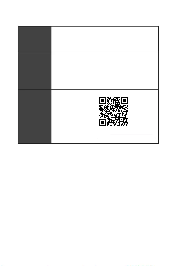
5
BIOS
y1 128 Mb flash
yUEFI AMI BIOS
yACPI 6.1 , SM BIOS 2.8
y
y
yDRAGON CENTER
yCPU-Z MSI GAMING
yIntel Extreme Tuning Utility
yGoogle Chrome™Google Google
yNorton™ Internet Security Solution
Dragon Center
yHardware Monitor
yEyerest
yLive Update
http://download.msi.com/
manual/mb/DRAGONCENTER2.pdf
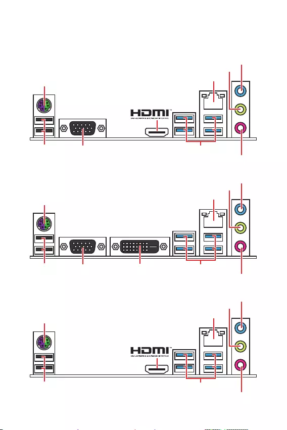
6 I/O
I/O
PS/2 /
B365M PRO-VH
USB 3.1 Gen1 (5Gbps)
VGA
USB 2.0
PS/2 /
B365M WIND
USB 3.1 Gen1 (5Gbps)USB 2.0
PS/2 /
B365M PRO-VD
USB 3.1 Gen1 (5Gbps)
VGA DVI-D
USB 2.0

7
I/O
/
10 Mbps
100 Mbps
1 Gbps
LED
CPU_FAN1
ATX_PWR1
EZ Debug LED
CPU
PCI_E1
SYS_FAN1
PCI_E2
PCI_E3
JCI1
DIMMA1
DIMMB1
SATA1
SATA2
JBAT1
JFP1
JFP2
CPU_PWR1
JUSB2
JUSB1
JTPM1
JUSB3
JCOM1
JAUD1
SATA34
SATA56
* CPU DIMM
50.83mm*
M2_1
(B365M PRO-VD,
B365M PRO-VH)
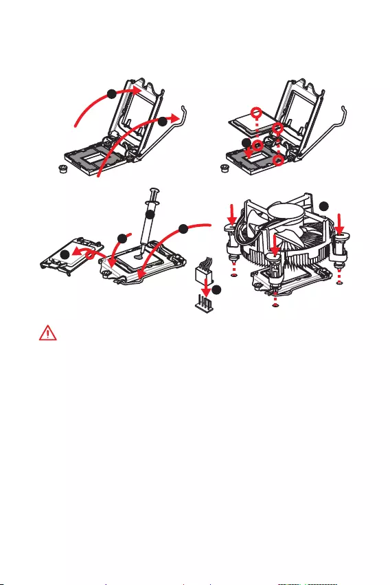
8
CPU
CPU CPU
y
y
CPU CPU
Return Merchandise Authorization (RMA)
y
CPU CPU
y
CPU
y
CPU CPU CPU
y
CPU CPU
y
/ /
1
4
6
5
78
9
3
2

9
y
DIMMA1
y
y
32 Windows
4GB 4GB
64 Windows
PCI_E1~3: PCIe
PCI_E1: PCIe 3.0 x16 (CPU )
PCI_E3: PCIe 3.0 x1 (PCH )
PCI_E2: PCIe 3.0 x1 (PCH )
y
MSI Gaming Series
y
, PCIe x16 , PCI_E1
y
DIMM
123
2

10
SATA1~6: SATA 6Gb/s
SATA 6Gb/s SATA
SATA3
SATA5
SATA4
SATA1
SATA2
SATA6
y
M.2 SATA M.2 SSD SATA1
y
SATA 90
y
SATA
JFP1, JFP2:
LED
1
2 10
9
JFP1
1 HDD LED + 2 Power LED +
3 HDD LED — 4 Power LED —
5 Reset Switch 6 Power Switch
7 Reset Switch 8 Power Switch
9 Reserved 10 No Pin
1
JFP2
1 Speaker — 2 Buzzer +
3 Buzzer — 4 Speaker +
HDD LED
RESET SW
HDD LED HDD LED —
HDD LED +
POWER LED —
POWER LED +
POWER LED
JFP1

11
M2_1: M.2 (M ) (B365M PRO-VD, B365M PRO-VH)
M.2 SSD M.2
ATX_PWR1, CPU_PWR1:
ATX
24
131
12
ATX_PWR1
1 +3.3V 13 +3.3V
2 +3.3V 14 -12V
3 Ground 15 Ground
4 +5V 16 PS-ON#
5 Ground 17 Ground
6 +5V 18 Ground
7 Ground 19 Ground
8 PWR OK 20 Res
9 5VSB 21 +5V
10 +12V 22 +5V
11 +12V 23 +5V
12 +3.3V 24 Ground
5
41
8
CPU_PWR1
1 Ground 5 +12V
2 Ground 6 +12V
3 Ground 7 +12V
4 Ground 8 +12V
ATX
1
2
3
4
5
y
Intel® RST PCIe M.2 SSD UEFI ROM
y
Intel® Optane™ Memory Ready
30

12
JUSB3: USB 3.1 Gen1
USB 3.1 Gen1
1
10 11
20
1Power 11 USB2.0+
2 USB3_RX_DN 12 USB2.0-
3 USB3_RX_DP 13 Ground
4 Ground 14 USB3_TX_C_DP
5 USB3_TX_C_DN 15 USB3_TX_C_DN
6 USB3_TX_C_DP 16 Ground
7 Ground 17 USB3_RX_DP
8 USB2.0- 18 USB3_RX_DN
9 USB2.0+ 19 Power
10 NC 20 No Pin
JUSB1, JUSB2: USB 2.0
USB 2.0
1
2 10
9
1VCC 2VCC
3 USB0- 4 USB1-
5 USB0+ 6 USB1+
7 Ground 8 Ground
9 No Pin 10 NC
y
VCC
y
USB iPadiPhone iPod MSI® DRAGON CENTER

13
JAUD1:
1
2 10
9
1 MIC L 2 Ground
3 MIC R 4 NC
5 Head Phone R 6 MIC Detection
7 SENSE_SEND 8 No Pin
9 Head Phone L 10 Head Phone Detection
JCOM1:
1
2 10
9
1 DCD 2 SIN
3 SOUT 4 DTR
5 Ground 6 DSR
7 RTS 8 CTS
9 RI 10 No Pin
LED
LED
CPU — CPU
DRAM —
VGA —
BOOT —
JTPM1: TPM
(TPM) TPM
1
2 14
13
1 LPC Clock 2 3V Standby power
3 LPC Reset 4 3.3V Power
5 LPC address & data pin0 6 Serial IRQ
7 LPC address & data pin1 8 5V Power
9 LPC address & data pin2 10 No Pin
11 LPC address & data pin3 12 Ground
13 LPC Frame 14 Ground
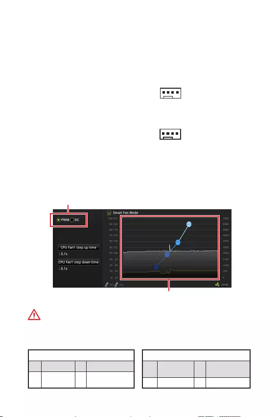
14
CPU_FAN1, SYS_FAN1:
(PWM) DC PWM
12V DC
3 ( PWM) PWM 100%
PWM DC
PWM
1 Ground 2 +12V
3 Sense 4 Speed Control
Signal
DC
1 Ground 2 Voltage
Control
3 Sense 4 NC
PWM
DC
PWM DC BIOS > HARDWARE MONITOR
PWM DC
PWM/ DC
CPU
1
CPU_FAN1
1
SYS_FAN1
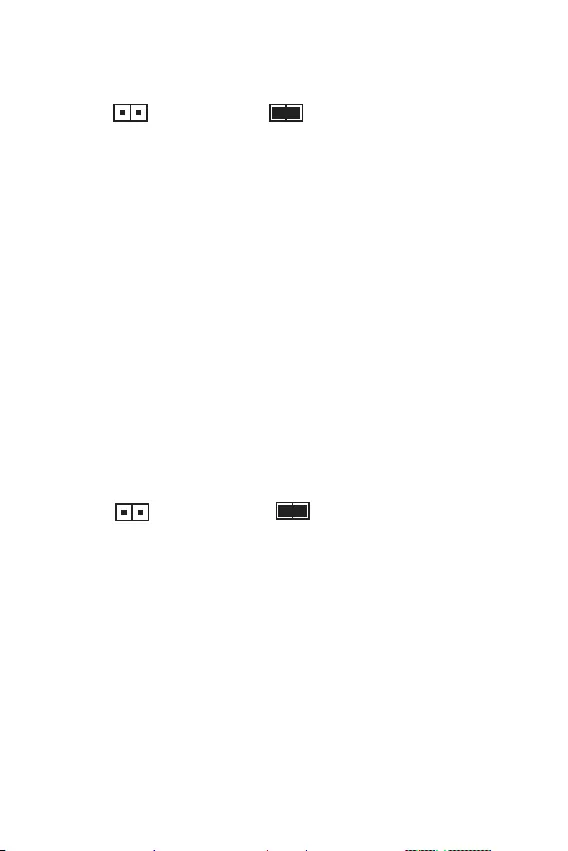
15
JBAT1: CMOS ( BIOS)
CMOS
CMOS
()
CMOS/
BIOS
BIOS
1.
2. JBAT1 5-10
3. JBAT1
4.
JCI1:
1. JCI1
2.
3. BIOS > Security > Chassis Intrusion Configuration
4. Chassis Intrusion Enabled
5. F10 Enter Yes
6.
1. BIOS > Security > Chassis Intrusion Configuration
2. Chassis Intrusion Reset.
3. F10 Enter Yes
()

16 BIOS
BIOS
T BIOS
y
BIOS BIOS
HELP BIOS
y
BIOS
BIOS
y DEL F11 Boot Menu
Delete
y MSI DRAGON CENTER GO2BIOS
BIOS
F1:
F2: /
F3:
F4: CPU
F5: Memory-Z
F6:
F7: EZ
F8:
F9:
F10: *
F12: USB FAT/ FAT32
Ctrl+F:
* F10

17
BIOS BIOS
BIOS
BIOS
BIOS
y BIOS F6
y CMOS
CMOS CMOS
BIOS
BIOS
M-FLASH BIOS
MSI BIOS BIOS USB
BIOS:
1. POST Del BIOS
2. USB
3. M-FLASH
4. BIOS BIOS
5. 100%
MSI DRAGON CENTER BIOS
BIOS
1. MSI DRAGON CENTER
2. BIOS Update (BIOS )
3. Scan ()
4. Download () BIOS
5. Next () In Windows mode Next () Start (
) BIOS
6. 100%

18
www.msi.com
Windows® 10
1.
2. Windows® 10
3.
4. (POST) F11
5.
6. Press any key to boot from CD or DVD…
7. Windows® 10
1. Windows® 10
2. MSI®
3. DVDSetup.exe
Windows MSI
DVDSetup.exe
4. /
5.
6.
7.
8.
1.
2.
3.
4.
5.
6.
7.

1
< 1>
…………………………………………………………………………. 2
…………………………………………………………………………………………………… 3
I/O ……………………………………………………………………………………… 6
B365M PRO-VH ………………………………………………………………………………………6
B365M PRO-VD ………………………………………………………………………………………6
B365M WIND ………………………………………………………………………………………….6
LANLED ……………………………………………………………………………..7
………………………………………………………………………….. 7
CPU ……………………………………………………………………………………………8
DIMM …………………………………………………………………………………………9
PCI_E1~3: PCIe …………………………………………………………………….9
JFP1JFP2: …………………………………………………….. 10
SATA1~6: SATA 6Gb/s …………………………………………………………….10
M2_1: M.2 (Key M) (B365M PRO-VD, B365M PRO-VH) ……………………11
ATX_PWR1CPU_PWR1: …………………………………………………11
JUSB1JUSB2: USB 2.0 ………………………………………………………….12
JUSB3: USB 3.1 Gen1 …………………………………………………………….12
JAUD1: ………………………………………………………13
JCOM1: …………………………………………………………..13
JTPM1: TPM ………………………………………………………….. 13
EZ Debug LED ………………………………………………………………………………………13
CPU_FAN1SYS_FAN1: …………………………………………………14
JCI1: ………………………………………………………… 15
JBAT1: CMOS (BIOS ) …………………………………………….. 15
BIOS ………………………………………………………………………………………. 16
BIOS …………………………………………………………………..16
BIOS ………………………………………………………………………………………17
BIOS …………………………………………………………………………17
OS …………………………………..18
Windows® 10 …………………………………………………………………… 18
……………………………………………………………………….. 18
…………………………………………………………………..18
MSI® B365M PRO-VD/ B365M PRO-VH/ B365M
WIND
BIOS

2
y(ESD)PC
y
y
y (ESD)
ESD
y
y
PC
y
PC
yPC
yPCPC
y
y
y
y
y
y
PC
y60OC (140OF)

3
CPU
LGA1151 Intel® Core™ 8/9Intel® Core™ /
Pentium® Gold / Celeron®
* Web
www.intel.com
Intel® B365
yDDR4 232GB
yDDR4 2666/ 2400/ 2133 MHz
y
yNon-ECC, un-buffered
yIntel® Extreme Memory Profile (XMP)
* www.msi.com
yPCIe 3.0 x16 x1
yPCIe 3.0 x1 x2
yVGA x12048×1536@50Hz,
2048×1280@60Hz, 1920×1200@60Hz (B365M PRO-
VD, B365M PRO-VH)
yDVI-D x11920×1200@60Hz
(B365M PRO-VD)
yHDMI™ 1.4 x14096×2160@30Hz
(B365M PRO-VH, B365M WIND)
* F
Intel® B365
ySATA 6Gb/s x6*
yM.2 x1 (Key M) (B365M PRO-VD, B365M PRO-VH)
PCIe 3.0 x4SATA 6Gb/s
2242/ 2260 /2280
Intel® Optane™ **
* M.2 SATA SSD M.2
SATA1
** Intel® Optane™MSI
BIOS

4
USB
Intel® B365
yUSB 3.1 Gen1 (SuperSpeed USB) x6 ( 4
Type-A USB 2)
yUSB 2.0 (High-speed USB) x6 ( 2 Type-A
USB 4)
yRealtek® ALC887
y7.1 HD
LAN Realtek RTL8111H Gigabit LAN x1
yPS/2 / x1
yUSB 2.0 x2
yVGA x1 (B365M PRO-VD, B365M PRO-VH)
yDVI-D x1 (B365M PRO-VD)
yHDMI™ x1 (B365M PRO-VHB365M WIND)
yUSB 3.1 Gen1 Type-A x4
yLAN (RJ45) x1
y x3
y24ATX x1
y8ATX 12V x1
yUSB 3.1 Gen1 x1 (2USB 3.1 Gen1
)
ySATA 6Gb/s x6
yCMOS x1
y x2
y x1
y x1
yUSB 2.0 x2 (4USB 2.0)
y x1
y4CPU x1
y4 x1
yTPM x1
I/O
NUVOTON NCT5567
5
yCPU/
yCPU/
yCPU/
ym-ATX
y8.9 in. x 7.3 in. (22.6 cm x 18.5 cm)
BIOS
y128 Mb x1
yUEFI AMI BIOS
yACPI 6.1 , SM BIOS 2.8
y
y
yDRAGON CENTER
yCPU-Z MSI GAMING
yIntel® Extreme Tuning Utility
yGoogle Chrome™, Google Toolbar, Google Drive
yNorton™ Internet Security Solution
y
yEyerest
yLive Update
http://download.
msi.com/manual/mb/
DRAGONCENTER2.pdf
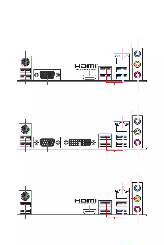
6I/O
I/O
PS/2/
B365M WIND
LAN
USB 3.1 Gen1 (5Gbps)USB 2.0
PS/2/
PS/2/
B365M PRO-VH
B365M PRO-VD
LAN
LAN
USB 3.1 Gen1 (5Gbps)
USB 3.1 Gen1 (5Gbps)
VGA
VGA DVI-D
USB 2.0
USB 2.0
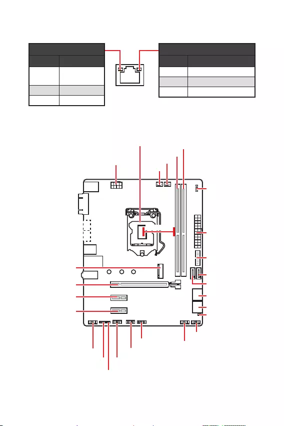
7
I/O
/ LED
Off
LED
Off 10 Mbps
100 Mbps
1 Gbps
LANLED
CPU_FAN1
ATX_PWR1
EZ Debug LED
CPU
PCI_E1
SYS_FAN1
PCI_E2
PCI_E3
JCI1
DIMMA1
DIMMB1
SATA1
SATA2
JBAT1
JFP1
JFP2
CPU_PWR1
JUSB2
JUSB1
JTPM1
JUSB3
JCOM1
JAUD1
SATA34
SATA56
* CPUDIMM
50.83mm*
M2_1
(B365M PRO-VD,
B365M PRO-VH)

8I/O
CPU
CPUCPU
y
CPU
y
CPUCPU CPU
CPU CPU
y
CPU CPUCPU
y
CPUCPU
y
CPUCPU
CPU
CPUCPU
y
CPUCPU
y
CPUCPUCPU
1
4
6
5
78
9
3
2

9
I/O I/O
y
DIMMA1
y
y
32bitWindows OS4GB
4GB64bit
Windows OS
PCI_E1~3: PCIe
PCI_E1: PCIe 3.0 x16 (CPU)
PCI_E3: PCIe 3.0 x1 (PCH)
PCI_E2: PCIe 3.0 x1 (PCH)
y
MSI Gaming Series Graphics Card Bolster
y
PCIe x16PCI_E1
y
DIMM
DIMM
123
2

10 I/O
SATA1~6: SATA 6Gb/s
SATA 6Gb/s
SATA
SATA3
SATA5
SATA4
SATA1
SATA2
SATA6
y
M.2 SATA SSD M.2SATA1
y
SATA 90
y
SATA
JFP1JFP2:
LED
1
2 10
9
JFP1
1 HDD LED + 2 Power LED +
3 HDD LED — 4 Power LED —
5 Reset Switch 6 Power Switch
7 Reset Switch 8 Power Switch
9 Reserved 10 No Pin
1
JFP2
1 Speaker — 2 Buzzer +
3 Buzzer — 4 Speaker +
HDD LED
RESET SW
HDD LED HDD LED —
HDD LED +
POWER LED —
POWER LED +
POWER LED
JFP1

11
I/O I/O
M2_1: M.2 (Key M) (B365M PRO-VD, B365M PRO-VH)
M.2 (SSD)M.2
ATX_PWR1CPU_PWR1:
ATX
24
131
12
ATX_PWR1
1 +3.3V 13 +3.3V
2 +3.3V 14 -12V
3 Ground 15 Ground
4 +5V 16 PS-ON#
5 Ground 17 Ground
6 +5V 18 Ground
7 Ground 19 Ground
8 PWR OK 20 Res
9 5VSB 21 +5V
10 +12V 22 +5V
11 +12V 23 +5V
12 +3.3V 24 Ground
5
41
8
CPU_PWR1
1 Ground 5 +12V
2 Ground 6 +12V
3 Ground 7 +12V
4 Ground 8 +12V
ATX
1
2
3
4
5
y
Intel® RST UEFI ROMPCIe M.2 SSD
y
Intel® Optane™
30

12 I/O
JUSB3: USB 3.1 Gen1
USB 3.1 Gen1
1
10 11
20
1Power 11 USB2.0+
2 USB3_RX_DN 12 USB2.0-
3 USB3_RX_DP 13 Ground
4 Ground 14 USB3_TX_C_DP
5 USB3_TX_C_DN 15 USB3_TX_C_DN
6 USB3_TX_C_DP 16 Ground
7 Ground 17 USB3_RX_DP
8 USB2.0- 18 USB3_RX_DN
9 USB2.0+ 19 Power
10 NC 20 No Pin
JUSB1JUSB2: USB 2.0
USB 2.0
1
2 10
9
1VCC 2VCC
3 USB0- 4 USB1-
5 USB0+ 6 USB1+
7 Ground 8 Ground
9 No Pin 10 NC
y
VCC
y
USB iPadiPhoneiPod MSI® DRAGON CENTER

13
I/O I/O
JAUD1:
1
2 10
9
1 MIC L 2 Ground
3 MIC R 4 NC
5 Head Phone R 6 MIC Detection
7 SENSE_SEND 8 No Pin
9 Head Phone L 10 Head Phone Detection
JCOM1:
1
2 10
9
1 DCD 2 SIN
3 SOUT 4 DTR
5 Ground 6 DSR
7 RTS 8 CTS
9 RI 10 No Pin
EZ Debug LED
LED
CPU — CPU
DRAM — DRAM
VGA — GPU
BOOT —
JTPM1: TPM
TPM (Trusted Platform Module)TPM
1
2 14
13
1 LPC Clock 2 3V Standby power
3 LPC Reset 4 3.3V Power
5 LPC address & data pin0 6 Serial IRQ
7 LPC address & data pin1 8 5V Power
9 LPC address & data pin2 10 No Pin
11 LPC address & data pin3 12 Ground
13 LPC Frame 14 Ground
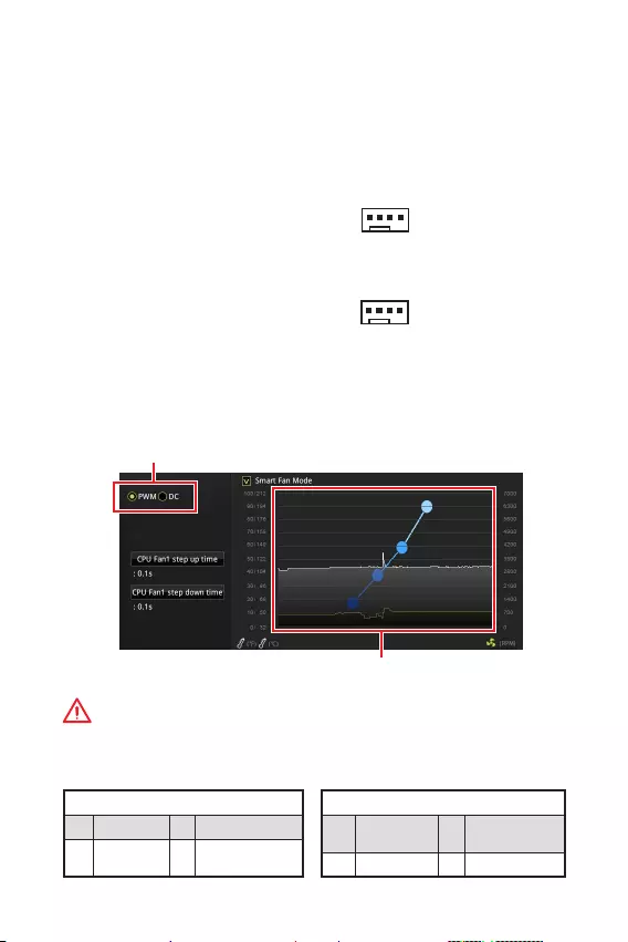
14 I/O
CPU_FAN1SYS_FAN1:
PWM ()DC PWM
12V
DC
3 (Non-PWM) PWM
100%
PWM/DC
PWM
1 Ground 2 +12V
3 Sense 4 Speed Control
Signal
DC
1 Ground 2 Voltage
Control
3 Sense 4 NC
PWM
DC
BIOS > HARDWARE MONITORPWMDC
PWM/DC
PWM/ DC
CPU
1
CPU_FAN1
1
SYS_FAN1

15
I/O I/O
JBAT1: CMOS (BIOS)
CMOS
CMOS
()CMOS /
BIOS
BIOS
1. PC
2. JBAT15-10
3. JBAT1
4.
JCI1:
()
1. JCI1/
2.
3. BIOS > Security > Chassis Intrusion Configuration
4. Chassis IntrusionEnabled
5. F10Enter
Yes
6.
1. BIOS > Security > Chassis Intrusion Configuration
2. Chassis IntrusionReset
3. F10Enter
Yes

16 BIOS
BIOS
BIOS
BIOS
y
BIOSBIOS
BIOS
HELP
y
BIOS
BIOS
yPress DEL key to enter Setup Menu, F11 to enter Boot Menu
Delete
yWindowsMSI DRAGON CENTER GO2BIOS
OKBIOS
F1:
F2: Favorites/
F3: Favorites
F4: CPU
F5: Memory-Z
F6: Optimized defaults
F7: EZ
F8: OC
F9: OC
F10: *
F12: USB (FAT/ FAT32
)
Ctrl+F:
* F10Yes
No

17
BIOS BIOS
BIOS
BIOSBIOS
yBIOS <F6> optimized defaults
yCMOS
CMOS PCBIOS
COMS
BIOS
M-FLASHBIOS
:
MSIWEB BIOS USB
BIOS:
1. POST<Delete> BIOS
2. BIOS USB USB
3. M-FLASH Yes
4. BIOS BIOS
5.
Live Update 6BIOS
:
LAN
BIOS:
1. MSI LIVE UPDATE 6
2. BIOS
3.
4. BIOS
5. Next In Windows mode Next Start
BIOS
6.

18 OS
OS
www.msi.com
Windows® 10
1. PC
2. Windows® 10
3. PCRestart
4. POST (Power-On Self Test)F11
5.
6. Press any key to boot from CD or DVD…
(Enter )
7. Windows® 10
1. Windows® 10
2. MSI®
3. Select to choose what happens with this disc
Run DVDSetup.exe Windows
MSI
DVDSetup.exe
4. /
5. Install
6.
7. OK
8. PC
1.
2. Utilities
3.
4. Install
5.
6. OK
7. PC
i
< 1> Regulatory Notices
FCC Compliance Statement
Note: This equipment has been tested and found
to comply with the limits for a Class B digital
device, pursuant to part 15 of the FCC Rules.
These limits are designed to provide reasonable
protection against harmful interference in
a residential installation. This equipment
generates, uses and can radiate radio frequency
energy and, if not installed and used in
accordance with the instructions, may cause
harmful interference to radio communications.
However, there is no guarantee that interference
will not occur in a particular installation. If this
equipment does cause harmful interference
to radio or television reception, which can be
determined by turning the equipment off and
on, the user is encouraged to try to correct the
interference by one or more of the following
measures:
yReorient or relocate the receiving antenna.
yIncrease the separation between the
equipment and receiver.
yConnect the equipment into an outlet on a
circuit different from that to which the receiver
is connected.
yConsult the dealer or an experienced radio/TV
technician for help.
Caution: Changes or modifications not
expressly approved by the party responsible for
compliance could void the users authority to
operate the equipment.
Tested to comply with FCC standards FOR
HOME OR OFFICE USE
This device complies with part 15 of the FCC
Rules. Operation is subject to the following two
conditions:
(1) This device may not cause harmful
interference, and (2) this device must accept any
interference received, including interference
that may cause undesired operation.
CE Conformity
Products bearing the CE marking
comply with one or more of the
following EU Directives as may be
applicable:
RED 2014/53/EU; Low Voltage Directive
2014/35/EU; EMC Directive 2014/30/EU; RoHS
Directive 2011/65/EU. Compliance with these
directives is assessed using applicable European
Harmonized Standards. The point of contact for
regulatory matters is MSI,
MSI-NL Eindhoven 5706 5692 ER Son.
C-Tick Compliance
B ( )
(B)
,
.
B
VCCI-B
Battery Information
European Union:
Batteries, battery packs, and
accumulators should not be
disposed of as unsorted household
waste. Please use the public
collection system to return, recycle,
or treat them in compliance with the
local regulations.
Taiwan:
For better environmental protection,
waste batteries should be collected
separately for recycling or special
disposal.
California, USA:
The button cell battery may contain
perchlorate material and requires
special handling when recycled or
disposed of in California.
For further information please visit:
http://www.dtsc.ca.gov/hazardouswaste/
perchlorate/
CAUTION: There is a risk of explosion, if battery
is incorrectly replaced.
Replace only with the same or equivalent type
recommended by the manufacturer.
Regulatory Notices

ii Regulatory Notices
WEEE (Waste Electrical and
Electronic Equipment) Statement
ENGLISH
To protect the global environment and as an
environmentalist, MSI must remind you that…
Under the European Union (“EU”) Directive on
Waste Electrical and Electronic Equipment,
Directive 2002/96/EC, which takes effect on
August 13, 2005, products of “electrical and
electronic equipment” cannot be discarded as
municipal wastes anymore, and manufacturers
of covered electronic equipment will be
obligated to take back such products at the end
of their useful life. MSI will comply with the
product take back requirements at the end of
life of MSI-branded products that are sold into
the EU. You can return these products to local
collection points.
DEUTSCH
Hinweis von MSI zur Erhaltung und Schutz
unserer Umwelt
Gemäß der Richtlinie 2002/96/EG über
Elektro- und Elektronik-Altgeräte dürfen
Elektro- und Elektronik-Altgeräte nicht
mehr als kommunale Abfälle entsorgt
werden. MSI hat europaweit verschiedene
Sammel- und Recyclingunternehmen
beauftragt, die in die Europäische Union
in Verkehr gebrachten Produkte, am Ende
seines Lebenszyklus zurückzunehmen. Bitte
entsorgen Sie dieses Produkt zum gegebenen
Zeitpunkt ausschliesslich an einer lokalen
Altgerätesammelstelle in Ihrer Nähe.
FRANÇAIS
En tant qu’écologiste et afin de protéger
l’environnement, MSI tient à rappeler ceci…
Au sujet de la directive européenne (EU) relative
aux déchets des équipement électriques et
électroniques, directive 2002/96/EC, prenant
effet le 13 août 2005, que les produits
électriques et électroniques ne peuvent être
déposés dans les décharges ou tout simplement
mis à la poubelle. Les fabricants de ces
équipements seront obligés de récupérer
certains produits en fin de vie. MSI prendra en
compte cette exigence relative au retour des
produits en fin de vie au sein de la communauté
européenne. Par conséquent vous pouvez
retourner localement ces matériels dans les
points de collecte.
РУССКИЙ
Компания MSI предпринимает активные
действия по защите окружающей среды,
поэтому напоминаем вам, что….
В соответствии с директивой Европейского
Союза (ЕС) по предотвращению загрязнения
окружающей среды использованным
электрическим и электронным оборудованием
(директива WEEE 2002/96/EC), вступающей
в силу 13 августа 2005 года, изделия,
относящиеся к электрическому и электронному
оборудованию, не могут рассматриваться
как бытовой мусор, поэтому производители
вышеперечисленного электронного
оборудования обязаны принимать его для
переработки по окончании срока службы. MSI
обязуется соблюдать требования по приему
продукции, проданной под маркой MSI на
территории EC, в переработку по окончании
срока службы. Вы можете вернуть эти изделия
в специализированные пункты приема.
ESPAÑOL
MSI como empresa comprometida con la
protección del medio ambiente, recomienda:
Bajo la directiva 2002/96/EC de la Unión
Europea en materia de desechos y/o equipos
electrónicos, con fecha de rigor desde el 13 de
agosto de 2005, los productos clasificados como
“eléctricos y equipos electrónicos” no pueden
ser depositados en los contenedores habituales
de su municipio, los fabricantes de equipos
electrónicos, están obligados a hacerse cargo
de dichos productos al termino de su período de
vida. MSI estará comprometido con los términos
de recogida de sus productos vendidos en la
Unión Europea al final de su periodo de vida.
Usted debe depositar estos productos en el
punto limpio establecido por el ayuntamiento
de su localidad o entregar a una empresa
autorizada para la recogida de estos residuos.
NEDERLANDS
Om het milieu te beschermen, wil MSI u eraan
herinneren dat….
De richtlijn van de Europese Unie (EU) met
betrekking tot Vervuiling van Electrische en
Electronische producten (2002/96/EC), die op
13 Augustus 2005 in zal gaan kunnen niet meer
beschouwd worden als vervuiling. Fabrikanten
van dit soort producten worden verplicht om
producten retour te nemen aan het eind van
hun levenscyclus. MSI zal overeenkomstig de
richtlijn handelen voor de producten die de
merknaam MSI dragen en verkocht zijn in de EU.
Deze goederen kunnen geretourneerd worden
op lokale inzamelingspunten.

iii
Regulatory Notices Regulatory Notices
SRPSKI
Da bi zaštitili prirodnu sredinu, i kao preduzeće
koje vodi računa o okolini i prirodnoj sredini, MSI
mora da vas podesti da…
Po Direktivi Evropske unije (“EU”) o odbačenoj
ekektronskoj i električnoj opremi, Direktiva
2002/96/EC, koja stupa na snagu od 13. Avgusta
2005, proizvodi koji spadaju pod “elektronsku i
električnu opremu” ne mogu više biti odbačeni
kao običan otpad i proizvođači ove opreme
biće prinuđeni da uzmu natrag ove proizvode
na kraju njihovog uobičajenog veka trajanja.
MSI će poštovati zahtev o preuzimanju ovakvih
proizvoda kojima je istekao vek trajanja, koji
imaju MSI oznaku i koji su prodati u EU. Ove
proizvode možete vratiti na lokalnim mestima
za prikupljanje.
POLSKI
Aby chronić nasze środowisko naturalne oraz
jako firma dbająca o ekologię, MSI przypomina,
że…
Zgodnie z Dyrektywą Unii Europejskiej (“UE”)
dotyczącą odpadów produktów elektrycznych
i elektronicznych (Dyrektywa 2002/96/EC),
która wchodzi w życie 13 sierpnia 2005, tzw.
“produkty oraz wyposażenie elektryczne i
elektroniczne “ nie mogą być traktowane jako
śmieci komunalne, tak więc producenci tych
produktów będą zobowiązani do odbierania ich w
momencie gdy produkt jest wycofywany z użycia.
MSI wypełni wymagania UE, przyjmując produkty
(sprzedawane na terenie Unii Europejskiej)
wycofywane z użycia. Produkty MSI będzie
można zwracać w wyznaczonych punktach
zbiorczych.
TÜRKÇE
Çevreci özelliğiyle bilinen MSI dünyada çevreyi
korumak için hatırlatır:
Avrupa Birliği (AB) Kararnamesi Elektrik
ve Elektronik Malzeme Atığı, 2002/96/EC
Kararnamesi altında 13 Ağustos 2005 tarihinden
itibaren geçerli olmak üzere, elektrikli ve
elektronik malzemeler diğer atıklar gibi
çöpe atılamayacak ve bu elektonik cihazların
üreticileri, cihazların kullanım süreleri bittikten
sonra ürünleri geri toplamakla yükümlü
olacaktır. Avrupa Birliği’ne satılan MSI markalı
ürünlerin kullanım süreleri bittiğinde MSI
ürünlerin geri alınması isteği ile işbirliği
içerisinde olacaktır. Ürünlerinizi yerel toplama
noktalarına bırakabilirsiniz.
ČESKY
Záleží nám na ochraně životního prostředí —
společnost MSI upozorňuje…
Podle směrnice Evropské unie (“EU”) o likvidaci
elektrických a elektronických výrobků 2002/96/
EC platné od 13. srpna 2005 je zakázáno
likvidovat “elektrické a elektronické výrobky”
v běžném komunálním odpadu a výrobci
elektronických výrobků, na které se tato
směrnice vztahuje, budou povinni odebírat
takové výrobky zpět po skončení jejich životnosti.
Společnost MSI splní požadavky na odebírání
výrobků značky MSI, prodávaných v zemích
EU, po skončení jejich životnosti. Tyto výrobky
můžete odevzdat v místních sběrnách.
MAGYAR
Annak érdekében, hogy környezetünket
megvédjük, illetve környezetvédőként fellépve az
MSI emlékezteti Önt, hogy …
Az Európai Unió („EU”) 2005. augusztus
13-án hatályba lépő, az elektromos és
elektronikus berendezések hulladékairól szóló
2002/96/EK irányelve szerint az elektromos
és elektronikus berendezések többé nem
kezelhetőek lakossági hulladékként, és az ilyen
elektronikus berendezések gyártói kötelessé
válnak az ilyen termékek visszavételére
azok hasznos élettartama végén. Az MSI
betartja a termékvisszavétellel kapcsolatos
követelményeket az MSI márkanév alatt az EU-n
belül értékesített termékek esetében, azok
élettartamának végén. Az ilyen termékeket a
legközelebbi gyűjtőhelyre viheti.
ITALIANO
Per proteggere l’ambiente, MSI, da sempre
amica della natura, ti ricorda che….
In base alla Direttiva dell’Unione Europea (EU)
sullo Smaltimento dei Materiali Elettrici ed
Elettronici, Direttiva 2002/96/EC in vigore dal 13
Agosto 2005, prodotti appartenenti alla categoria
dei Materiali Elettrici ed Elettronici non possono
più essere eliminati come rifiuti municipali: i
produttori di detti materiali saranno obbligati
a ritirare ogni prodotto alla fine del suo ciclo di
vita. MSI si adeguerà a tale Direttiva ritirando
tutti i prodotti marchiati MSI che sono stati
venduti all’interno dell’Unione Europea alla fine
del loro ciclo di vita. È possibile portare i prodotti
nel più vicino punto di raccolta

iv Regulatory Notices
JIS C 0950
JIS C 0950 200671
http://www.msi.com/html/popup/csr/
cemm_jp.html
http://tw.msi.com/html/popup/csr_tw/
cemm_jp.html
India RoHS
This product complies with the “India
E-waste (Management and Handling) Rule
2011” and prohibits use of lead, mercury,
hexavalent chromium, polybrominated
biphenyls or polybrominated diphenyl ethers
in concentrations exceeding 0.1 weight % and
0.01 weight % for cadmium, except for the
exemptions set in Schedule 2 of the Rule.
Türkiye EEE yönetmeliği
Türkiye Cumhuriyeti: EEE Yönetmeliğine
Uygundur
Україна обмеження на наявність
небезпечних речовин
Обладнання відповідає вимогам Технічного
регламенту щодо обмеження використання
деяких небезпечних речовин в електричному
та електронному обладнані, затвердженого
постановою Кабінету Міністрів України від 3
грудня 2008 № 1057.
Vit Nam RoHS
K t ngày 01/12/2012, tt c các sn phm
do công ty MSI sn xut tuân th Thông t s
30/2011/TT-BCT quy nh tm thi v gii hn
hàm lng cho phép ca mt s hóa cht c
hi có trong các sn phm in, in t
Environmental Policy
yThe product has been designed
to enable proper reuse of parts
and recycling and should not be
thrown away at its end of life.
yUsers should contact the local
authorized point of collection for
recycling and disposing of their end-of-life
products.
yVisit the MSI website and locate a nearby
distributor for further recycling information.
Users may also reach us at gpcontdev@msi.
com for information regarding proper Disposal,
Take-back, Recycling, and Disassembly of MSI
products.
Chemical Substances Information
In compliance with chemical substances
regulations, such as the EU REACH Regulation
(Regulation EC No. 1907/2006 of the European
Parliament and the Council), MSI provides
the information of chemical substances in
products at:
http://www.msi.com/html/popup/csr/evmtprtt_
pcm.html
v
Regulatory Notices Regulatory Notices
(Pb)
(Hg)
(Cd)
(Cr(VI))
(PBB)
(PBDE)
*
**
SJ/T 11364
: GB/T 26572
: GB/T 26572
RHS
* :
**
(Pb)
(Hg)
(Cd)
(Cr+6)
(PBB)
(PBDE)
1. 0.1 wt % 0.01 wt %
2.
3.

vi Regulatory Notices
Technical Support
If a problem arises with your system and no
solution can be obtained from the user guide,
please contact your place of purchase or local
distributor. Alternatively, please try the following
help resources for further guidance.
yVisit the MSI website for technical guide,
BIOS updates, driver updates, and other
information: http://www.msi.com
yRegister your product at: http://register.
msi.com
Copyright
Micro-Star Intl Co.,Ltd.
Copyright © 2019 All rights reserved.
The MSI logo used is a registered trademark of
Micro-Star Intl Co., Ltd. All other marks and
names mentioned may be trademarks of their
respective owners. No warranty as to accuracy
or completeness is expressed or implied. MSI
reserves the right to make changes to this
document without prior notice.
Revision History
Version 1.0, 2018/11, First release.
Version 1.1, 2019/04, HDMI only for WIND.
1
<變數 1> Contents
Contents
Safety Information ………………………………………………………………………………. 2
Specifications ………………………………………………………………………………………3
Rear I/O Panel ……………………………………………………………………………………..6
B365M PRO-VH/ B365M PLUS………………………………………………………………….6
B365M PRO-VD ………………………………………………………………………………………6
B365M WIND ………………………………………………………………………………………….6
LAN Port LED Status Table ………………………………………………………………………7
Overview of Components ……………………………………………………………………..7
CPU Socket ……………………………………………………………………………………………8
DIMM Slots …………………………………………………………………………………………….9
PCI_E1~3: PCIe Expansion Slots ………………………………………………………………9
JFP1, JFP2: Front Panel Connectors ………………………………………………………10
SATA1~6: SATA 6Gb/s Connectors…………………………………………………………..10
M2_1: M.2 Slot (Key M) (B365M PRO-VD, B365M PRO-VH, B365M PLUS) ……11
ATX_PWR1, CPU_PWR1: Power Connectors…………………………………………….11
JUSB1, JUSB2: USB 2.0 Connectors ……………………………………………………….12
JUSB3: USB 3.1 Gen1 Connector ……………………………………………………………12
JAUD1: Front Audio Connector ………………………………………………………………. 13
JCOM1: Serial Port Connector ……………………………………………………………….13
JTPM1: TPM Module Connector ……………………………………………………………..13
EZ Debug LED ………………………………………………………………………………………13
CPU_FAN1, SYS_FAN1: Fan Connectors ………………………………………………….14
JCI1: Chassis Intrusion Connector ………………………………………………………….15
JBAT1: Clear CMOS (Reset BIOS) Jumper ……………………………………………….15
BIOS Setup ……………………………………………………………………………………….. 16
Entering BIOS Setup ……………………………………………………………………………..16
Resetting BIOS ……………………………………………………………………………………..17
Updating BIOS ………………………………………………………………………………………17
Installing OS, Drivers & Utilities ………………………………………………………….18
Installing Windows
®
10 ………………………………………………………………………….18
Installing Drivers ………………………………………………………………………………….18
Installing Utilities ………………………………………………………………………………….18
Thank you for purchasing the MSI
®
B365M PRO-VD/ B365M
PRO-VH/ B365M WIND/ B365M PLUS motherboard. This
User Guide gives information about board layout, component
overview, BIOS setup and software installation.
MSI B365M Pro VD, B365M Pro VH, B365M Wind, B365M Plus Specification
The MSI B365M series, comprising the Pro VD, Pro VH, Wind, and Plus models, offers a range of motherboards designed for users seeking reliable performance and essential features. Each motherboard in this series is built around the Intel B365 chipset, supporting 9th and 8th Generation Intel Core processors, Pentium Gold, and Celeron processors in an LGA 1151 socket.
The B365M Pro VD model provides a foundation with essential connectivity options, including multiple USB ports, HDMI, VGA, and DVI-D outputs for versatile display connectivity. It supports dual-channel DDR4 memory with a maximum capacity of 64GB, ensuring efficient multitasking and performance for everyday computing tasks.
The Pro VH variant enhances usability with additional features like improved audio capabilities and a more robust set of I/O ports, catering to users who demand better multimedia experiences. It maintains the core specifications of the Pro VD while offering enhanced durability and connectivity.
The B365M Wind model is designed with a focus on balanced performance and cooling efficiency. It includes optimized fan headers and improved thermal design to ensure stable operation under load. This model is ideal for users who prioritize system stability and thermal management.
Finally, the B365M Plus model tops the series with advanced features such as reinforced PCIe slots for graphics cards, enhanced audio quality, and additional expansion slots for increased versatility. It is tailored for users who require a more robust platform for gaming or professional applications.
Overall, the MSI B365M series provides a spectrum of options to suit different user needs, from basic computing tasks to more demanding applications, ensuring reliability and performance across various use cases.
MSI B365M Pro VD, B365M Pro VH, B365M Wind, B365M Plus F.A.Q.
To update the BIOS on your MSI B365M motherboard, download the latest BIOS version from the MSI support website. Extract the files to a USB drive formatted in FAT32. Restart your computer and enter BIOS by pressing the ‘Delete’ key during boot. Navigate to ‘M-Flash’ and follow the on-screen instructions to update the BIOS.
If your motherboard does not boot, check the power connections and ensure the RAM and CPU are properly seated. Clear the CMOS by removing the battery or using the jumper method. If the problem persists, try booting with minimal hardware to identify faulty components.
To enable XMP, restart your computer and enter BIOS by pressing the ‘Delete’ key. Navigate to the ‘OC’ tab, find the ‘XMP’ option, and set it to ‘Enabled’. Save and exit the BIOS to apply the settings.
Yes, you can control fan speed through the BIOS. Enter the BIOS, go to the ‘Hardware Monitor’ section, and adjust the fan curves or speed settings according to your preference.
Check if the monitor is properly connected and powered on. Verify that the graphics card (if any) is correctly seated. Try using a different cable or port. If the issue persists, reset the BIOS settings and test with a different monitor.
MSI B365M motherboards support a maximum of 64GB of DDR4 RAM, with a maximum speed of 2666 MHz. Ensure you are using compatible memory modules for optimal performance.
To reset the BIOS, enter the BIOS setup by pressing the ‘Delete’ key during startup. Navigate to the ‘Save & Exit’ tab and select ‘Restore Defaults’. Confirm the action and save the changes before exiting.
Yes, MSI B365M motherboards support NVMe SSDs through the M.2 slot. Ensure the SSD is properly installed in the M.2 slot and detected in the BIOS for optimal performance.
Ensure the SATA cables are securely connected to both the motherboard and the hard drive. Check the BIOS to see if the drive is recognized. If not, try connecting the drive to a different SATA port or replacing the cable.
To improve performance, ensure your BIOS and drivers are up to date. Enable XMP for RAM, optimize the boot sequence, and consider upgrading components like the CPU or installing an SSD for faster load times.
|
Код: 116679 Извините, товара сейчас нет в наличии
Бесплатная доставка Извините, товара сейчас нет в наличии Сравнить Новости интернет-магазина «Лаукар»:23.04.2025 26.02.2025 17.02.2025 Дополнительная информация в категории Материнская плата:Таблица Авторизованных сервисных центров по брендам. Описание Инструкция Отзывы (0) В интернет-магазине бытовой техники «Лаукар» Вы можете скачать инструкцию к товару Материнская плата MSI B365M PRO-VDH совершенно бесплатно. Все инструкции, представленные на сайте интернет-магазина бытовой техники «Лаукар», предоставляются производителем товара. Для того чтобы скачать инструкцию, Вам необходимо нажать на ссылку «скачать инструкцию», расположенную ниже, а в случае, если ссылки нет, Скачать инструкцию Смотреть инструкцию 
Фирма-производитель оставляет за собой право на внесение изменений в конструкцию, дизайн и комплектацию товара: Материнская плата MSI B365M PRO-VDH. Пожалуйста, сверяйте информацию о товаре с информацией на |