

This product
complies with the 325
regulations effective
January 1,1993.
Owner’s Manual contains:
installation, operating, maintenance, & warranty instructions.
For residential use only.
Digital Intelligence for the Garage
M-4700
M-4500
Marantec America Corporation
675 Heathrow Drive Lincolnshire, IL 60069 U.S.A.
Phone 1-888-622-2489 • Fax 847-478-0348
Access Systems
www.marantecamerica.com
Automatically The Best Choice

© Copyright 2004 All Rights Reserved.
1. INTRODUCTION . . . . . . . . . . . . . . . . . . . . . . . . . . . . . . . . . . . . . . . . . . . . . . . . . . . . . . . . . . . . . . . . . . . . . . 3
2. ADVANCED FEATURES . . . . . . . . . . . . . . . . . . . . . . . . . . . . . . . . . . . . . . . . . . . . . . . . . . . . . . . . . . . . . . . . . 3
3. IMPORTANT SAFETY INFORMATION . . . . . . . . . . . . . . . . . . . . . . . . . . . . . . . . . . . . . . . . . . . . . . . . . . . . . . 3
4. TOOLS . . . . . . . . . . . . . . . . . . . . . . . . . . . . . . . . . . . . . . . . . . . . . . . . . . . . . . . . . . . . . . . . . . . . . . . . . . . . .4
5. GARAGE . . . . . . . . . . . . . . . . . . . . . . . . . . . . . . . . . . . . . . . . . . . . . . . . . . . . . . . . . . . . . . . . . . . . . . . . . . . .4
6. OPENER PACKAGE CONTENTS . . . . . . . . . . . . . . . . . . . . . . . . . . . . . . . . . . . . . . . . . . . . . . . . . . . . . . . . . . . 6
7. IMPORTANT INSTALLATION INSTRUCTIONS . . . . . . . . . . . . . . . . . . . . . . . . . . . . . . . . . . . . . . . . . . . . . . . . . 7
8. INSTALLATION STEPS . . . . . . . . . . . . . . . . . . . . . . . . . . . . . . . . . . . . . . . . . . . . . . . . . . . . . . . . . . . . . . . . . 8
8-1. MEASURE AND MARK DOOR AREA . . . . . . . . . . . . . . . . . . . . . . . . . . . . . . . . . . . . . . . . . . . . . . . . .8
8-2. INSTALL HEADER BRACKET . . . . . . . . . . . . . . . . . . . . . . . . . . . . . . . . . . . . . . . . . . . . . . . . . . . . . . . . 8
8-3. INSTALL DOOR BRACKET TO DOOR . . . . . . . . . . . . . . . . . . . . . . . . . . . . . . . . . . . . . . . . . . . . . . . . . . 9
8-4. ATTACH RAIL TO OPENER HEAD . . . . . . . . . . . . . . . . . . . . . . . . . . . . . . . . . . . . . . . . . . . . . . . . . . . 10
8-5. ATTACH RAIL TO HEADER BRACKET . . . . . . . . . . . . . . . . . . . . . . . . . . . . . . . . . . . . . . . . . . . . . . . .11
8-6. POSITION OPENER FOR MOUNTING . . . . . . . . . . . . . . . . . . . . . . . . . . . . . . . . . . . . . . . . . . . . . . . .11
8-7. MOUNT OPENER TO CEILING . . . . . . . . . . . . . . . . . . . . . . . . . . . . . . . . . . . . . . . . . . . . . . . . . . . . . . 12
8-8. CONNECT ARM TO DOOR AND TROLLEY . . . . . . . . . . . . . . . . . . . . . . . . . . . . . . . . . . . . . . . . . . . . . 13
8-9. CHECK EMERGENCY RELEASE . . . . . . . . . . . . . . . . . . . . . . . . . . . . . . . . . . . . . . . . . . . . . . . . . . . . . 13
8-10. INSTALL PHOTO EYE SAFETY SYSTEM . . . . . . . . . . . . . . . . . . . . . . . . . . . . . . . . . . . . . . . . . . . . . .14
8-11. INSTALL WALL CONTROL . . . . . . . . . . . . . . . . . . . . . . . . . . . . . . . . . . . . . . . . . . . . . . . . . . . . . . . . 15
8-12. CONNECTING WIRES TO POWERHEAD . . . . . . . . . . . . . . . . . . . . . . . . . . . . . . . . . . . . . . . . . . . . . . .15
8-13. INSTALL LIGHT BULBS AND LENSES . . . . . . . . . . . . . . . . . . . . . . . . . . . . . . . . . . . . . . . . . . . . . . . . 16
8-14. CONNECT TO POWER . . . . . . . . . . . . . . . . . . . . . . . . . . . . . . . . . . . . . . . . . . . . . . . . . . . . . . . . . . . . 17
8-15. CONTROL PANEL . . . . . . . . . . . . . . . . . . . . . . . . . . . . . . . . . . . . . . . . . . . . . . . . . . . . . . . . . . . . . . . 18
8-16. SET THE ADJUSTMENTS . . . . . . . . . . . . . . . . . . . . . . . . . . . . . . . . . . . . . . . . . . . . . . . . . . . . . . . . . 18
8-17. TEST SAFETY REVERSAL . . . . . . . . . . . . . . . . . . . . . . . . . . . . . . . . . . . . . . . . . . . . . . . . . . . . . . . . . 20
8-18. ALIGN AND TEST PHOTO EYES . . . . . . . . . . . . . . . . . . . . . . . . . . . . . . . . . . . . . . . . . . . . . . . . . . . . 20
8-19. APPLY LABELS TO INSIDE OF GARAGE . . . . . . . . . . . . . . . . . . . . . . . . . . . . . . . . . . . . . . . . . . . . . .21
8-20. ATTACH OWNER’S MANUAL TO WALL . . . . . . . . . . . . . . . . . . . . . . . . . . . . . . . . . . . . . . . . . . . . . . . 21
9. IMPORTANT SAFETY INSTRUCTIONS . . . . . . . . . . . . . . . . . . . . . . . . . . . . . . . . . . . . . . . . . . . . . . . . . . . . . 21
10. TRANSMITTERS . . . . . . . . . . . . . . . . . . . . . . . . . . . . . . . . . . . . . . . . . . . . . . . . . . . . . . . . . . . . . . . . . . . . . 22
11. OPERATION OF YOUR OPENER . . . . . . . . . . . . . . . . . . . . . . . . . . . . . . . . . . . . . . . . . . . . . . . . . . . . . . . . . . 23
12. HOMELINK® TRANSCEIVER . . . . . . . . . . . . . . . . . . . . . . . . . . . . . . . . . . . . . . . . . . . . . . . . . . . . . . . . . . . .23
13. MODULAR RECEIVER . . . . . . . . . . . . . . . . . . . . . . . . . . . . . . . . . . . . . . . . . . . . . . . . . . . . . . . . . . . . . . . . . 23
14. TENSION ADJUSTMENT . . . . . . . . . . . . . . . . . . . . . . . . . . . . . . . . . . . . . . . . . . . . . . . . . . . . . . . . . . . . . . . 24
15. RAIL LENGTH ADJUSTMENT—FOR PROFESSIONAL USE ONLY . . . . . . . . . . . . . . . . . . . . . . . . . . . . . . . . . . 24
16. RAIL ASSEMBLY . . . . . . . . . . . . . . . . . . . . . . . . . . . . . . . . . . . . . . . . . . . . . . . . . . . . . . . . . . . . . . . . . . . . 25
17. POWER HEAD ASSEMBLY . . . . . . . . . . . . . . . . . . . . . . . . . . . . . . . . . . . . . . . . . . . . . . . . . . . . . . . . . . . . . 26
18. ACCESSORIES . . . . . . . . . . . . . . . . . . . . . . . . . . . . . . . . . . . . . . . . . . . . . . . . . . . . . . . . . . . . . . . . . . . . . . 28
19. HAVING A PROBLEM? . . . . . . . . . . . . . . . . . . . . . . . . . . . . . . . . . . . . . . . . . . . . . . . . . . . . . . . . . . . . . . . . 29
20. TROUBLESHOOTING—FOR PROFESSIONAL INSTALLER ONLY . . . . . . . . . . . . . . . . . . . . . . . . . . . . . . . . . . . 30
21. MAINTENANCE AND ADJUSTMENTS . . . . . . . . . . . . . . . . . . . . . . . . . . . . . . . . . . . . . . . . . . . . . . . . . . . . . 31
22. MAINTENANCE RECORD . . . . . . . . . . . . . . . . . . . . . . . . . . . . . . . . . . . . . . . . . . . . . . . . . . . . . . . . . . . . . . 31
23. WARRANTY INFORMATION . . . . . . . . . . . . . . . . . . . . . . . . . . . . . . . . . . . . . . . . . . . . . . . . . . . . . . . . . . . . 32
24. NEED HELP OR SERVICE? . . . . . . . . . . . . . . . . . . . . . . . . . . . . . . . . . . . . . . . . . . . . . . . . . . . . . . . . . . . . . 32
OWNER’S MANUAL CONTENTS

3
Congratulations on purchasing your Marantec®Professional Series Garage Door Opener System, the most
innovative opener available today. This stylishly designed digital opener with a wide range of accessories is
engineered to provide the smoothest, quietest and safest operation to compliment any home. Advanced
technology results in the opener being capable of easily moving almost any properly balanced residential
garage door, and at the same time providing state-of-the-art safety features to detect obstructions and to
stop and reverse the door, thus helping to protect persons and property near the door.
This opener includes numerous state-of-the-art features to provide you, the user, with years of
trouble-free, convenient, and safe use of your automatic garage door opener.
■ Precision Controlled DC Motor, Complete with Automatic Soft Start and Soft Stop Feature: The
opener automatically detects when your door is almost fully closed or fully opened, and gradually slows
the door down before it reaches its fully closed or opened position. During start-up, the door starts moving
slowly and gradually ramps up to full speed for the full travel of your door. This reduces the possible
damaging effects of the sudden starts and stops associated with some other openers, and results in the
smooth operation and increased life of your door and hardware.
■ Built-In Safety Features: Including patented drive system that delivers only the optimum power needed to
move your door safely — Every time!
■ Modular Receiver Concept (patented): Plug-in your choice of frequency module.
■ Photo Eye (Infrared) Safety System: State-of-the-art infrared beam system helps detect obstructions in
the path of your door and automatically reverses closing door travel, helping to protect persons and
property near the door.
■ Convenient Status Display: To indicate the status of your door opener at any time. Especially useful if
troubleshooting is necessary.
■ Quiet, Smooth Operation: Precision engineering and carefully selected materials result in extremely
smooth and quiet operation, unmatched by conventional garage door openers.
This manual is essential to the safe and proper installation, operation, and maintenance of your opener. Read
and follow all guidelines and operating instructions before the first use of this product. Store the manual in a
safe, easily accessible location.
3. IMPORTANT SAFETY INFORMATION
2. ADVANCED FEATURES
1. INTRODUCTION
WARNING means that severe injury or death could
result from failure to follow instructions.
CAUTION means that property damage or injury
could result from failure to follow instructions.
Operate the garage door opener at 120V, 60MHz to avoid opener damage.
Garage doors are heavy, moving objects. When coupled with an automatic opener, electrical power is also
present. If not properly installed, balanced, operated, and maintained, an automatic door can become
dangerous and cause serious injury or death. Please pay close attention to the WARNING and CAUTION
notices that appear throughout this manual. Failure to follow certain instructions may result in damage to
the door or door opener, or may result in severe injury or death to yourself or others.
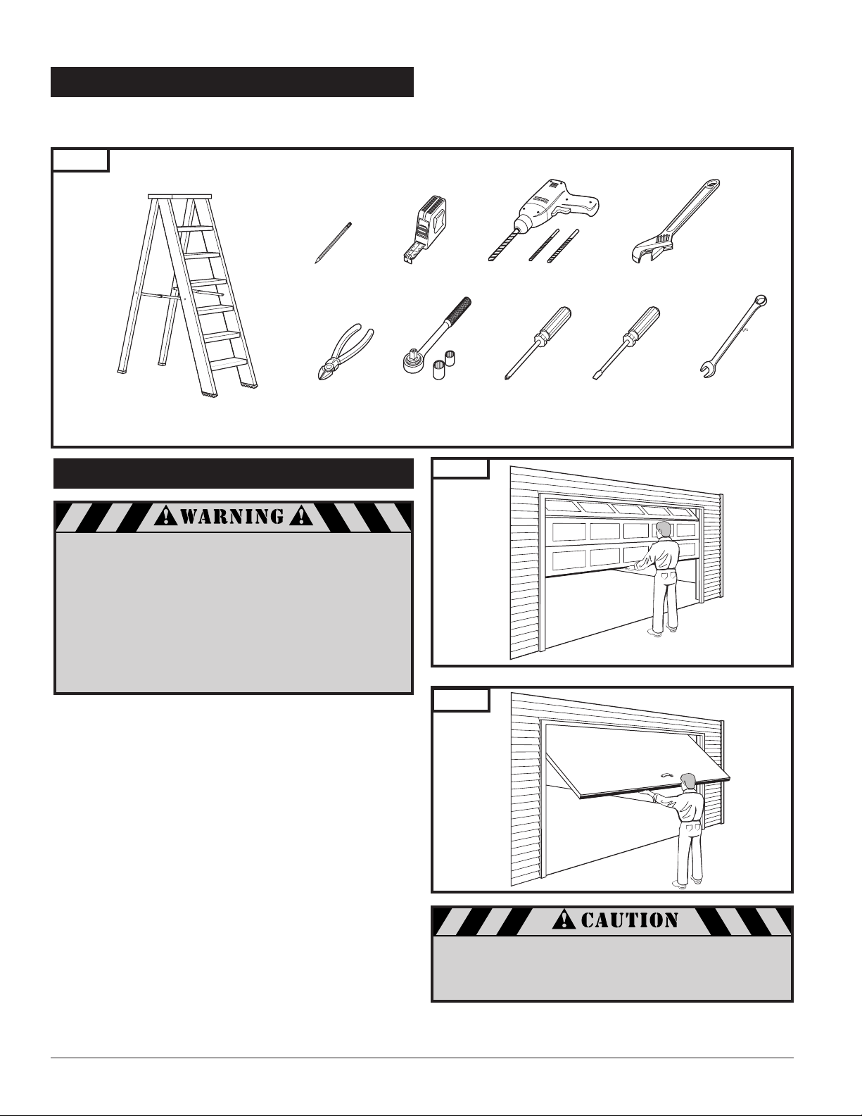
The instructions will refer to the tools shown below for proper installation, adjustment, and maintenance of the garage
door opener. Additional tools may be required depending on your particular installation.
4. TOOLS
Fig. 1
Take a moment to survey your garage and garage door.
■ Is there an access door besides the garage door? If not,
you should install an emergency key release kit.
■ With the garage door closed, check alignment of door
and garage floor. The gap, if any, should be no more than
1/4″. If the gap is larger than this, repair floor or door
before installing opener.
■ The opener is intended for installation on a properly
balanced and adjusted garage door. DO NOT INSTALL IF
DOOR IS UNBALANCED OR BROKEN.
■ Check balance of door in mid travel and during full range
of opening and closing. Lift the door about half way,
as shown in Fig. 2 & 3. Release the door. It should remain
in place, supported by its springs. Raise and lower the
door fully to check for binding or sticking.
■ If door is out of balance or needs repair, DO NOT ADJUST
IT YOURSELF. CALL A QUALIFIED GARAGE DOOR SERVICE
PROFESSIONAL to adjust your door.
■ If your door is over 7 ft. high, you will need a longer rail.
See section “6. Rail Assembly» on p. 6 of this manual for
availability of longer rails.
5. GARAGE
A garage door is a heavy moving object and can
cause serious injury or death. An unbalanced door
might not reverse when required, and can increase
the risk of injury. If your garage door is out of
balance, or if it binds or sticks, call for professional
garage door service. Garage doors, springs,
pulleys, cables, and hardware are under extreme
tension and can cause serious injury or death.
Do not try to adjust them yourself. Ropes left
on a garage door could cause someone to become
entangled and could kill them. Remove all ropes
connected to the door before installing your opener.
Fig. 2
Fig. 3
Sectional Door
One-Piece Door
To prevent damage to steel, aluminum, fiberglass or
glass panel doors, always reinforce the inside of the
door both vertically and horizontally with steel or
angle iron bracing.
The best solution is to follow the instructions for your particular garage door or contact the garage door manufacturer
for proper reinforcement instructions.
Pencil Tape Measure
Stepladder
Wire Cutters
Ratchet and Sockets
(1/2”, 7/16”)
Drill and Drill Bits
Phillips
Screwdriver
Adjustable Wrench
Flat-Tip
Screwdriver
Wrench
7/16”
5
5. GARAGE (cont’d)
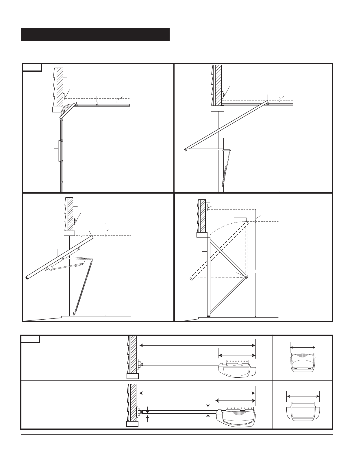
Check the type of door construction you have. The information contained in the figures below will be referred to later
in the manual for proper installation on the different door types.
Fig. 4
Sectional Door
with Curved Track
One-Piece Door
with Horizontal Track
One-Piece Door
with Jamb Hardware without Track
One-Piece Door
with Pivot Hardware without
Track
GARAGE DOOR OPENER SYSTEM OVERALL DIMENSIONS (7′ DOOR)
One Light Opener
Two Light Opener
Fig. 5
Door
Header Wall
Header Bracket
Header Wall
Highest Point of
Highest Point of
Door Travel
Header Bracket
Door Travel
1-1/4” Clearance
Distance
3-3/4” Clearance
Door
Header Bracket
Header Wall
Header Bracket
Highest Point of
Door Travel
Header Wall
Highest Point of
Door Travel
3-3/4”
Clearance
1-1/4”
Clearance
Distance
Door
Jamb
Hardware
Distance
10′ 10″
10′ 6 1/2″
Door
Pivot
14 1/2″
Distance
8 1/2″
18″
14 1/2″
1/2″ 1 3/8″
6
Items shown not actual size.
POWERHEADS
6. OPENER PACKAGE CONTENTS
Fig. 6
Models (per application)
Belt Chain
7’ Door ML-807B ML-807C
8’ Door ML-808B ML-808C
10’ Door ML-810B ML-810C
M-4500
(One Light
Powerhead)
M-4700
(Two Light
Powerhead)
The following items are included with your Garage Door Opener. All hardware components located in GDO carton.
The accessories are packaged with their respective hardware in separate packs for ease of identification and use.
ACCESSORIES
Wall Control Panel
(with Hardware Kit)
Photo Eye Safety System
(with Hardware)
Hardware Kit
Fig. 7
RAIL ASSEMBLY
(packaged in separate carton)
Fig. 8
Garage Door Opener
Safety Labels and Literature
2-Channel Mini Transmitter
M-Line
Series M-4500
(Power Head with
1 Light Lens)
®
2-Two Channel
Mini Transmitters
Transmitter
Visor
Clip
Programming
Connector
Warranty
Card
Curved Door Arm
Cover
Header Bracket
Screw Caps (2)
Drywall Anchors (2)
“C” Brackets (2)
Tapered-Head Screws
(2)
Machine screws
(2)
30 Ft. 2-Conductor
Wire
Staples (10)
Door Bracket
Plastite Screw (4): 6 x 14
Clevis Pin (1): 5/16” x 7/8”
Cotter Ring (1)
Carriage Bolt (2): 1/4”-20 x 2”
Lock Washer (2): 1/4”
Hex Nut (2): 1/4”-20
Lag Screw (2): 5/16” x 1-5/8”
Hex Bolt (2): 5/16”-18 x 3/4”
Lock Nut (2): 5/16”-18
Header Clevis Pin (1): 1/4” x 3-1/4”
Cotter Ring (1)
Hex Head T
ek Screw (2): 1/4 x 3/4”
Straight Door Arm
7
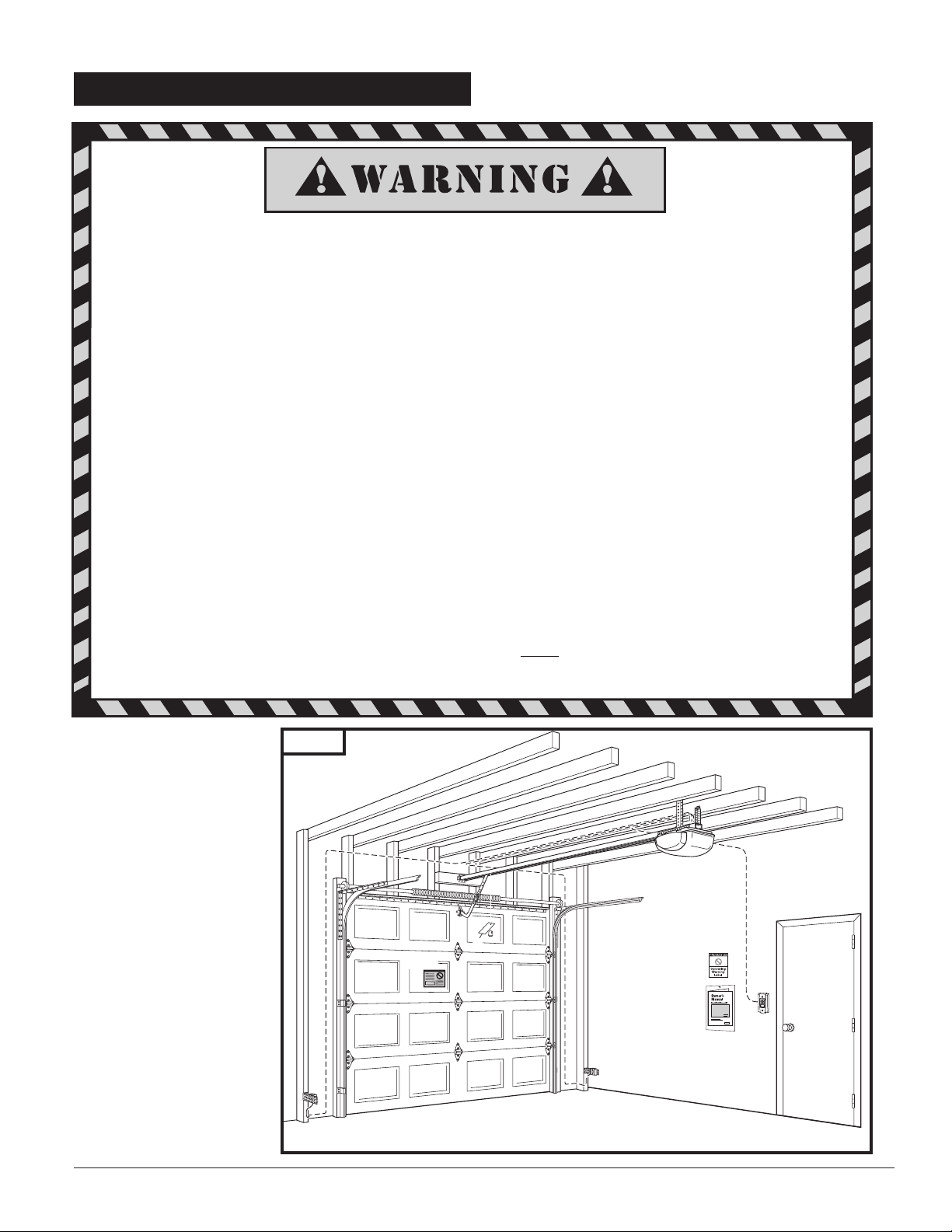
7. IMPORTANT INSTALLATION INSTRUCTIONS
IMPORTANT INSTALLATION INSTRUCTIONS
TO REDUCE THE RISK OF SEVERE INJURY OR DEATH:
1. READ AND FOLLOW ALL INSTALLATION INSTRUCTIONS.
2. Check with the door manufacturer to determine if additional reinforcement is required to support the door
prior to installation of the garage door opener.
3. Install garage door opener only on a properly balanced garage door. An improperly balanced door could
cause serious injury. Have a qualified service person make repairs to garage door cables, spring assemblies,
and other hardware before installing the opener.
4. Remove all ropes and remove or make inoperative all locks connected to the garage door before installing
opener.
5. If possible, install the door opener 7 feet or more above the floor. Adjust the emergency release cord so that
knob hangs 6 feet above the floor.
6. Do not connect the opener to source of power until this manual instructs you to do so.
7. Locate the wall control panel or wall button: (a) within sight of door, (b) at a minimum height of 5 feet
above the ground so small children cannot reach it, and (c) away from all moving parts of the door.
8. Place the Operating Warning Label next to the wall control panel or wall button in a prominent location.
Affix Safety Label on inside of garage door. The Emergency Release Tag must remain on the emergency
release cord.
9. After installing the opener, test Safety Reversal System. Door MUST
reverse when it contacts a 1-1/2 inch high
object (or a 2×4 laid flat) on the floor.
For Important Safety Instructions see page 21.
Shown on the right is an
overall view of a completed
garage door opener system
installed on a sectional
door. The arrangement is
similar for a one-piece door
(except for differences
described later in this
manual).
Fig. 9
Garage Door
Safety Label
Tag
Operating
Warnin g
Label
Owner’s
Manual
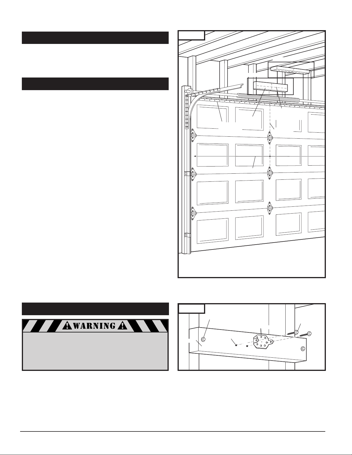
Fig. 10
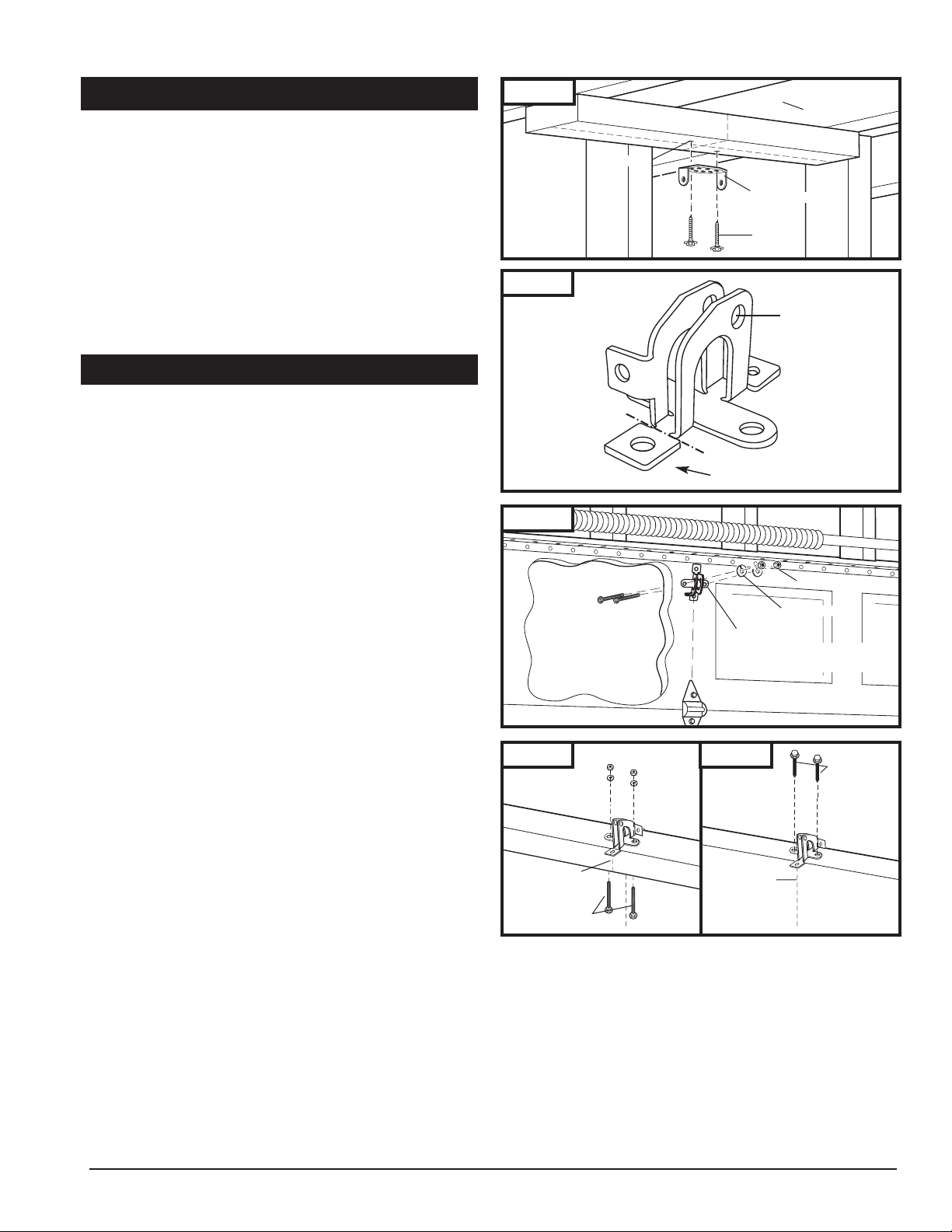
Identify a sound structural support on header wall above
garage door for header bracket mounting. See Fig. 11. If
appropriate header does not exist, replace or install a new
support using a 2×4 or 2×6 board. Fasten it securely using lag
screws (not provided) to structural supports of garage.
Before starting your installation, the door and the header
above the door must be measured and marked. This way, the
appropriate brackets can be mounted at the correct locations
avoiding installation and operating difficulties later.
MARK VERTICAL CENTER LINE:
■ Measure door width, then locate the center point (Fig.10).
■ Mark a vertical line on the upper half of your door, on the
top edge of your door, and on the header, through the
center point.
MEASURE DOOR’S HIGHEST TRAVEL POINT:
(Review Figs. on p. 5 for details)
■ Open door to its highest travel point and measure from
the garage floor to the top of door.
■ Write down this distance.
FOR SECTIONAL DOORS AND ONE-PIECE
DOORS WITH HORIZONTAL TRACK:
Add 1-1/4″ to the door travel height (measured above).
FOR ONE-PIECE DOORS WITHOUT TRACK:
Add 3-3/4″ to the door travel height (measured above).
MARK HORIZONTAL LINE FOR HEADER
BRACKET LOCATION:
■ Close door and measure the required distance (determined
above) from the garage floor to the header.
■ Mark a horizontal line, intersecting the vertical center
line, on header. This is the position at which the bottom
of the header bracket should be installed.
■ In case of minimal clearance above the door, the header
bracket may be mounted to the ceiling. In this case,
extend the vertical center line onto the ceiling, and mark
a horizontal line on the ceiling no further than 4″ from
the header wall. The header bracket should be mounted
no farther than this distance from the header wall.
8-2. INSTALL HEADER BRACKET
8-1. MEASURE AND MARK DOOR AREA
8. INSTALLATION STEPS
If the header bracket is not rigidly fastened to a sound
structural support on the header wall or ceiling, the
safety reverse system may not work and could cause
serious injury or death. DO NOT move or adjust springs
or garage door hardware, as these parts are under
extreme tension and could cause injury or death.
Horizontal
Reinforcement
Bracket
Door Width
See Fig. 11
Header
See Fig. 12
Horizontal Line for
Header Bracket
Height
Vertical
Center Line
Header
Lag Screw for Header installation
if necessary (not provided)
Header Bracket
Pilot Hole
5/16 x 1-5/8”
Lag Screw
9
■ Mark pilot holes location on header through holes where
lag screws will be inserted. IMPORTANT: See Fig. 11 for
which header bracket holes to use.
■ Drill 3/16″ pilot holes into header, and install bracket with
lag screws (5/16 x 1-5/8”) provided.
■ Tighten lag screws firmly.
NOTE: Follow the same procedure if header (shown in Fig.
11) runs vertically instead of horizontally and is the only
option for mounting header bracket to header wall. In case
of minimal clearance above the garage door, the header
bracket may be mounted to the ceiling. Follow the same
steps above to ensure a sound surface for mounting.
A. FOR SECTIONAL DOORS:
Wood Sectional Doors (Fig. 14)
■ Position door bracket (Fig. 13) along vertical center line of
door with pin hole facing top of the door and top edge of
the bracket 4” to 5” below top edge of the door, or
roughly at the same height as top rollers on the door.
■ Mark locations of securement holes through door bracket.
■ Drill two 1/4″ holes through door for securement of
door bracket.
■ Insert carriage bolts (1/4” x 2”) from the outside through
door and bracket, then secure with lock washers and nuts
from the inside.
■ Tighten nuts firmly.
Metal Sectional Doors
■ Attach door bracket with two teck screws (provided) per
door manufacturer recommendations.
B. FOR ONE-PIECE DOORS:
Before starting the installation of the door bracket, cut off
mounting leg from opposite side of pin hole.
One-Piece Doors with Exposed Frames (Fig. 15)
■ Position center of door bracket on the center line on the
top edge of door.
■ Mark the position where carriage bolts will go through
bracket, and drill two 1/4″ holes through top frame of
door.
■ Install carriage bolts from the bottom, through door
frame and bracket, and secure with lock washer and nut
from top.
■ Tighten nuts firmly.
8-3. INSTALL DOOR BRACKET TO DOOR
8-2. INSTALL HEADER BRACKET (cont’d)
Fig. 12
One-Piece Doors without Exposed Frames (Fig. 16)
■ For doors without exposed frames, use alternate method
of mounting door bracket.
■ Mark and drill two 3/16″ pilot holes into top of frame,
then secure bracket with 5/16″ x 1-5/8″ lag screws
(not provided).
One-Piece Door
with Exposed Frame:
Install with Carriage Bolts
One-Piece Door
without Exposed Frame:
Install with Lag Screws (not provided)
Fig. 13
Fig. 14
Fig. 15 Fig. 16
cut off for one-piece
door only
Pin Hole
Insert 1/4-20 x 2”
from outside of door
Pilot Hole
Carriage Bolts
Header Bracket
Lag Screw
Lock Washer
Door Bracket
Wood Sectional
Ceiling
1/4-20 Nut
Doors
Garage Door
Center Line
Carriage Bolts
Garage Door
Center Line
Lag Screws
NOTE: Rail comes fully preassembled with straight door
arm already attached.
■ Unpack one-piece preassembled rail.
■ Leave straight door arm taped inside rail for safe and
convenient installation—it will be untaped and used later.
■ Position door opener head with control panel facing front
of garage. Rest opener head on cardboard or protective
surface on floor so opener does not get scratched. Chassis
side of opener (with motor shaft sticking out) facing up.
■ Position rail onto opener chassis by lining up rail sprocket
opening with motor head shaft (Fig. 17A). Make sure shaft
engages teeth inside rail sprocket. Press rail down firmly
onto shaft and opener chassis. DO NOT HAMMER.
■ Position 2 «C» brackets over rail and onto chassis. Flanges
on «C» brackets MUST fit into cutout area on chassis (Fig.
17B).
■ Insert screws 6 x 14 through bracket holes and into chassis
holes, and tighten screws firmly to hold rail to head (Fig.
17C).
■ For sectional doors, proceed to step 8-5.
ADDITIONAL STEP FOR ONE-PIECE
DOORS ONLY:
IMPORTANT NOTE: For installation on One-Piece Doors
only, the straight door arm that is factory installed
onto the rail must be replaced by the curved door
arm supplied as part of hardware in powerhead box.
This must be done after attaching rail to powerhead,
before moving to step 8-5.
■ Turn rail and opener head over so that open channel in
rail faces up.
■ Untape straight door arm that is secured inside rail.
■ Remove and save the two phillips head screws that are
securing the door arm pin and straight door arm (Fig. 18).
■ Lift arm and pin straight out of slot in trolley, and remove
pin from straight door arm.
■ Insert pin into short side of curved door arm as shown.
■ Orient arm so that long side extends away from trolley.
■ Carefully insert pin and door arm into slot in trolley.
Push pin into slot with door arm so pin is fully seated into
trolley slot. IMPORTANT: Pin must be straight and seated
properly into recessed area in trolley. See Fig. 18A.
■ Secure pin and curved arm with the two phillips screws
which were removed from trolley—DO NOT use any
other screws. Tighten screws firmly.
■ Turn rail and powerhead over so that open channel
in rail faces down. Now proceed to Step 8-5.
8-4. ATTACH RAIL TO OPENER HEAD
10
When fastening the rail to the opener,
use only the screws provided. Use of any
other screws may result in opener falling
from ceiling and causing damage
to persons or property in the garage.
Rail Sprocket
Opening
Rail
Motor Head
Shaft
C. Secure “C”
Brackets
to Chassis
6×14
Screw
A. Place Rail
onto Chassis
B. Position “C”
Brackets
to Chassis
“C” Brackets
A. Loosen Screws
B. Remove Pin
C. Feed Pin through Curved
Door Arm Hole
Correctly seated pin.
D. Reinsert Pin and Arm Firmly
and Squarely, Tighten Screws
Incorrectly seated pin.
Loading…
MARANTEC A 60 N — Инструкция по эксплуатации и монтажу
Электронный блок управления
Формат: pdf | Размер: 1.4 Mb | Язык: Русский
MARANTEC A70R — Инструкция по эксплуатации и монтажу
Аксессуары
Формат: pdf | Размер: 351.5 Kb | Язык: Русский
MARANTEC B 60 N — Инструкция по эксплуатации и монтажу
Электронный блок управления
Формат: pdf | Размер: 1.4 Mb | Язык: Русский
MARANTEC Comfort 211 — Инструкция по эксплуатации и монтажу
Автоматика для гаражных ворот
Формат: pdf | Размер: 3.9 Mb | Язык: Русский
MARANTEC Comfort 220 Описание — Инструкция по эксплуатации и монтажу
Автоматика для гаражных ворот
Формат: pdf | Размер: 420.2 Kb | Язык: Русский
MARANTEC Comfort 220 Рисунки — Инструкция по эксплуатации и монтажу
Автоматика для гаражных ворот
Формат: pdf | Размер: 697.5 Kb | Язык: Русский
MARANTEC COMFORT 220.2 — Инструкция по эксплуатации и монтажу
Автоматика для гаражных ворот
Формат: pdf | Размер: 3.8 Mb | Язык: Русский
MARANTEC Comfort 250 Описание — Инструкция по эксплуатации и монтажу
Автоматика для гаражных ворот
Формат: pdf | Размер: 718.5 Kb | Язык: Русский
MARANTEC Comfort 250 Рисунки — Инструкция по эксплуатации и монтажу
Автоматика для гаражных ворот
Формат: pdf | Размер: 2.3 Mb | Язык: Русский
MARANTEC COMFORT 250.2 — Инструкция по эксплуатации и монтажу
Автоматика для гаражных ворот
Формат: pdf | Размер: 3.8 Mb | Язык: Русский
MARANTEC COMFORT 250.2 SPEED — Инструкция по эксплуатации и монтажу
Автоматика для гаражных ворот
Формат: pdf | Размер: 3.8 Mb | Язык: Русский
MARANTEC Comfort 252 Описание — Инструкция по эксплуатации и монтажу
Автоматика для гаражных ворот
Формат: pdf | Размер: 718.1 Kb | Язык: Русский
MARANTEC Comfort 252 Рисунки — Инструкция по эксплуатации и монтажу
Автоматика для гаражных ворот
Формат: pdf | Размер: 2.3 Mb | Язык: Русский
MARANTEC COMFORT 252.2 — Инструкция по эксплуатации и монтажу
Автоматика для гаражных ворот
Формат: pdf | Размер: 3.8 Mb | Язык: Русский
MARANTEC Comfort 515 — Инструкция по эксплуатации и монтажу
Автоматика для распашных ворот
Формат: pdf | Размер: 6.2 Mb | Язык: Русский
MARANTEC Comfort 520 — Инструкция по эксплуатации и монтажу
Автоматика для распашных ворот
Формат: pdf | Размер: 4.4 Mb | Язык: Русский
MARANTEC Comfort 580 — Инструкция по эксплуатации и монтажу
Автоматика для распашных ворот
Формат: pdf | Размер: 3.5 Mb | Язык: Русский
MARANTEC Comfort 830 — Инструкция по эксплуатации и монтажу
Автоматика для откатных ворот
Формат: pdf | Размер: 3.5 Mb | Язык: Русский
MARANTEC Comfort 850 — Инструкция по эксплуатации и монтажу
Автоматика для откатных ворот
Формат: pdf | Размер: 3.4 Mb | Язык: Русский
MARANTEC Comfort 850 S — Инструкция по эксплуатации и монтажу
Автоматика для откатных ворот
Формат: pdf | Размер: 3.6 Mb | Язык: Русский
Автоматика для ворот | Размер файла: 615.8 Kb | Формат файла: pdf
MARANTEC AS 210 B — Инструкция по установке и эксплуатации (RU)
Автоматика для ворот | Размер файла: 759.8Kb | Формат файла: pdf
Marantec C14 C15 Блоки управления — Инструкция, Программирование (RU)
Автоматика для ворот | Размер файла: 831.3Kb | Формат файла: pdf
Marantec C14N C15N Блоки управления — Инструкция, Программирование (RU)
Автоматика для ворот | Размер файла: 897.3Kb | Формат файла: pdf
Marantec C24N C25N Блоки управления — Инструкция, Программирование (RU)
Автоматика для ворот | Размер файла: 1.4 Mb | Формат файла: pdf
MARANTEC COMFORT 150, 160 — Инструкция по установке и эксплуатации
Автоматика для ворот | Размер файла: 1.3 Mb | Формат файла: pdf
MARANTEC COMFORT 150DC, 160DC — Инструкция по установке и эксплуатации
Автоматика для ворот | Размер файла: 3.5 Mb | Формат файла: pdf
MARANTEC COMFORT 211 — Инструкция по установке и эксплуатации (RU)
Автоматика для ворот | Размер файла: 4.9 Mb | Формат файла: pdf
MARANTEC COMFORT 211 ACCU, SOLAR — Инструкция по установке и эксплуатации
Автоматика для ворот | Размер файла: 3 Mb | Формат файла: pdf
MARANTEC COMFORT 211 EOS — Инструкция по установке и эксплуатации (RU)
Автоматика для ворот | Размер файла: 4.9 Mb | Формат файла: pdf
MARANTEC COMFORT 211 EOS ACCU, SOLAR — Инструкция по установке и эксплуатации
Автоматика для ворот | Размер файла: 7.1 Mb | Формат файла: pdf
MARANTEC COMFORT 211 EOS BATTERY BACKUP — Инструкция по установке и эксплуатации
Автоматика для ворот | Размер файла: 3.9Mb | Формат файла: pdf
Marantec Comfort 211 Привод для гаражных ворот — Инструкция по монтажу и эксплуатации (RU)
Автоматика для ворот | Размер файла: 420.2Kb | Формат файла: pdf
Marantec Comfort 220 Привод для гаражных ворот — Инструкция, Часть руководства с описанием (RU)
Автоматика для ворот | Размер файла: 697.5Kb | Формат файла: pdf
Marantec Comfort 220 Привод для гаражных ворот — Инструкция, Часть руководства с фотографиями и чертежами (RU)
Автоматика для ворот | Размер файла: 4.2 Mb | Формат файла: pdf
MARANTEC COMFORT 220, 250, 252 — Инструкция по установке и эксплуатации (RU)
11 лет на рынке
производство
монтаж
ремонт
Онлайн заявка
Инструкции для автоматики в Москве
Инструкции по установке, регулированию и введению в эксплуатацию автоматических систем помогут правильно обращаться с данной продукцией. Строго придерживаясь правил, можно качественно установить конструкцию и обеспечить длительность ее использования. Только в этом случае производится гарантийное и сервисное обслуживание продукции. Материал представлен в PDF формате, для работы с которым рекомендуется Adobe Reader.
Воротные системы Алютех
Инструкция по монтажу секционных, гаражных ворот (7,83 Mb)
Автоматика для гаражных ворот BFT Botticelli (10,3 Mb)
Автоматика для гаражных ворот BFT EOS120 (2,5 Mb)
Автоматика для гаражных ворот BFT Tiziano (12,7 Mb)
Автоматика для промышленных ворот BFT Iglea LB (0,7 Mb)
Автоматика для промышленных ворот BFT Uglisse (2 Mb)
Автоматика для промышленных ворот BFT Urano BT (2,8 Mb)
Автоматика для распашных ворот BFT A 180SW (10,2 Mb)
Автоматика для распашных ворот BFT E 5 (0,91 Mb)
Автоматика для распашных ворот BFT Igea (1,69 Mb)
Автоматика для распашных ворот BFT Lux L (0,67 Mb)
Автоматика для распашных ворот BFT Phobos N BT (1,93 Mb)
Автоматика для распашных ворот BFT Phobos N (0,84 Mb)
Автоматика для распашных ворот BFT Phobos NL BT (4,92 Mb)
Автоматика для распашных ворот BFT Phobos NL (0,7 Mb)
Автоматика для распашных ворот BFT Virgo (3,48 Mb)
Инструкция к блокам управления BFT
Блок управления BFT Alcor N (0,6 Mb)
Блок управления BFT Altair P (1,2 Mb)
Блок управления BFT Elba (4,3 Mb)
Блок управления BFT Elmec (0,4 Mb)
Блок управления BFT Hydra N (1,9 Mb)
Блок управления BFT Mitto (0,41 Mb)
Блок управления BFT Sirio MA (0,8 Mb)
Инструкция к пультам управления BFT
Пульт управления BFT Cellula RFL (1,97 Mb)
Пульт управления BFT Cellula 130 (0,87 Mb)
Пульт управления BFT Clonix E (0,58 Mb)
Пульт управления BFT Clonix 1-2 (1,98 Mb)
Пульт управления BFT Clonix 4 RTE (4,1 Mb)
Инструкция к автоматике CAME
Автоматика для гаражных ворот CAME v600, v700 (833 Kb)
Автоматика для гаражных ворот CAME v700e (2,91 Mb)
Автоматика для гаражных ворот CAME v900e (3,38 Mb)
Автоматика для откатных ворот CAME B4337, 4353 (0,25 Mb)
Автоматика для откатных ворот CAME BK-1200P (2,26 Mb)
Автоматика для откатных ворот CAME BX-P (2,32 Mb)
Автоматика для промышленных ворот CAME BK-1200P (2,26 Mb)
Автоматика для промышленных ворот CAME CBX (4,14 Mb)
Автоматика для промышленных ворот CAME C BY, C BYT, C100 (0,32 Mb)
Автоматика для распашных ворот CAME ATI A3024N, A5024N (1,16 Mb)
Автоматика для распашных ворот CAME AXO AX302304, AX402306, AX412306, AX71230 (3 Mb)
Автоматика для распашных ворот CAME Ferni F1024 (1,12 Mb)
Инструкция к блокам управления CAME
Блоки управления CAME Ferni LB18 (0,25 Mb)
Блоки управления CAME Ferni LB38 (4,76 Mb)
Блоки управления CAME Ferni ZA3 (0.47 Mb)
Блоки управления CAME Ferni ZA4 (0,4 Mb)
Блоки управления CAME Ferni ZBK, ZBKE (0,53 Mb)
Блоки управления CAME Ferni ZBX 7 (1,13 Mb)
Блоки управления CAME Ferni ZC 3 (1,79 Mb)
Блоки управления CAME Ferni ZC 4 (0,37 Mb)
Инструкция к радиоуправлению CAME
Радиоуправление CAME TOP 432NA (0,57 Mb)
Радиоуправление CAME TOP 432SA (0,43 Mb)
Радиоуправление CAME TWIN (1,19 Mb)
Инструкция к шлагбаумам CAME
Шлагбаум CAME G2080 (3,88 Mb)
Шлагбаум CAME G2500 (0,27 Mb)
Шлагбаум CAME G02804 (1,15 Mb)
Шлагбаум CAME G4000, G4001 (0,48 Mb)
Шлагбаум CAME G6000, G6001 (0,49 Mb)
Инструкция к элементам безопасности CAME
Фотоэлемент безопасности CAME DIR (0,18 MB)
Стойка для фотоэлементов CAME DIR L, DIR LN (0,25 Mb)
Сигнальная лампа CAME KIARO IN, KIARO 24 IN (0,16 Mb)
Инструкция к автоматике MARANTEC
Автоматика для гаражных ворот MARANTEC Comfort 220.2, 250.2, 252.2, 250.2 (3,88 Mb)
Автоматика для гаражных ворот MARANTEC GDO 500S/L — 700S/L (2,67 Mb)
Автоматика для промышленных ворот MARANTEC Dynamic xs.base (8,6 Mb)
Автоматика для промышленных ворот MARANTEC Dynamic xs.plus (11,1 Mb)
Автоматика для промышленных ворот MARANTEC STA 1 (1,59 Mb)
Аксессуары к MARANTEC Control 401 (0,89 Mb)
Аксессуары к MARANTEC Special 630 (0,45 Mb)
Аксессуары к MARANTEC Special 802, 803 (1,89 Mb)
Инструкция к автоматике NICE
Автоматика для гаражных ворот NICE Climber (1,1 Mb)
Автоматика для гаражных ворот NICE SHEL50KIT, SHEL75KIT (2,1 Mb)
Автоматика для гаражных ворот NICE SP 6065, SP 6100 (2,1 Mb)
Автоматика для гаражных ворот NICE Spido (1,37 Mb)
Автоматика для гаражных ворот NICE Spin (0,71 Mb)
Автоматика для гаражных ворот NICE Spin 10KCE, Spin 11KCE (0,68 Mb)
Автоматика для откатных ворот NICE Robus 350 (0,58 Mb)
Автоматика для откатных ворот NICE Robus 600/600P, 1000/1000P (0,66 Mb)
Автоматика для откатных ворот NICE RO500 (0,67 Mb)
Автоматика для откатных ворот NICE ROBO (1,39 Mb)
Автоматика для откатных ворот NICE ROBO V.010 (1,16 Mb)
Автоматика для откатных ворот NICE RUN1800, RUN1800P, RUN2500, RUN2500P (1,39 Mb)
Автоматика для откатных ворот NICE Thor1500Kit (1,49 Mb)
Автоматика для промышленных ворот NICE Soon (0,99 Mb)
Автоматика для промышленных ворот NICE Sumo (1,95 Mb)
Автоматика для промышленных ворот NICE Tom S (2,33 Mb)
Автоматика для распашных ворот NICE HYPPO (1,94 Mb)
Автоматика для распашных ворот NICE WINGO (2,8 Mb)
Автоматика для распашных ворот NICE MOBY 4005 (2,1 Mb)
Автоматика для распашных ворот NICE MOBY 5016 (1,92 Mb)
Автоматика для распашных ворот NICE METRO (1,28 Mb)
Автоматика для распашных ворот NICE POP (1,74 Mb)
Автоматика для распашных ворот NICE TOONA (2,29 Mb)
Автоматика для распашных ворот NICE WALKY (3,56 Mb)
Инструкция к аксессуарам NICE
Барьер инфракрасного излучения NICE серия FE, FEP, FI, BF (0,58 Mb)
Фотоэлемент NICE FT210 (1,52 Mb)
Система контроля доступа NICE MOON (1,65 Mb)
Трос внешней разблокировки NICE MU (0,2 Mb)
Аккумуляторная батарея NICE PS224 (0,38 Mb)
Аккумуляторная батарея NICE PS424 (0,12 Mb)
Инструкция по программированию и монтажу NICE Seld (0,39 Mb)
Инструкция и предупреждения для монтажников NICE Wallyght (0,67 Mb)
Инструкция к блокам управления
Блок управления NICE серии А0, А0/R для jдного привода (0,18 Mb)
Электронная плата управления двустворчатых ворот версии A6-A6F, A700F (1,87 Mb)
Блок управления NICE Mindy A60 (0,78 Mb)
Блок управления NICE Mindy A400 (1 Mb)
Блок управления NICE Mindy A500 (0.86 Mb)
Блок управления NICE Mindy A824 (1,43 Mb)
Блок управления NICE Mindy A924 (0,2 Mb)
Электронная плата управления для механизмов ROBO PLUS и CLIMBER (1,6 Mb)
Блок управления NICE Signo SIA 20 (0,29 Mb)
Блок управления NICE Moon MC424 (1,49 Mb)
Блок управления NICE Moon MC824H (1,43 Mb)
Блок управления NICE POA1 (0,79 Mb)
Электронная плата управления для механизма ROBO/OTTO/THOR (0,56 Mb)
Электронная плата управления для механизмов NICE Spider 6060, Spider 6065, Spider 6100 (0,99 Mb)
Электронная плата управления для шлагбаума WIL (1,33 Mb)
Инструкция к радиоуправлению NICE
Радиоуправление с кварцевой стабизацией серия FLO и VERY (0,93 Mb)
Пульт дистанционного управления NiceOne (0,37 Mb)
Приемник NiceOne (0,66 Mb)
Пульты дистанционного управления NiceWay (0,3 Mb)
Радиоприемник SMX2, SMX2R (0,44 Mb)
Радиоприемник SMXI (0,27 Mb)
Радиоприемник SMXI, SMIF, SMXIS (0,23 Mb)
Блок управления NICE Mindy TT1L (0,56 Mb)
Блок управления NICE Mindy TT1N (1,2 Mb)
Блок управления со встроенным приемником NICE TT2N (0,46 Mb)
Передатчик с динамическим кодом NICE TTX4 (0,18 Mb)
Инструкция к шлагбаумам
Автоматический шлагбаум NICE Signo (0,59 Mb)
Электромеханический шлагбаум NICE WIL (1,62 Mb)
Автоматический шлагбаум NICE X-Bar (0,74 Mb)
Инструкция к воротам AN MOTORS
Комплект для автоматизации гаражных ворот ASG/KIT (1,86 Mb)
Привод для автоматизации секционных ворот ASI40 (0,79 Mb)
Привод для автоматизации промышленных, секционных ворот ASI50 (1,83 Mb)
Привод для автоматизации откатных ворот ASL500/1000/2000 (1,24 Mb)
Инструкция к аксессуарам AN MOTORS
Фотоэлемент APHOTO (0,19 Mb)
Радиокодовая беспроводная цифровая клавиатура DIP (0,72 Mb)
Внешний радиоприемник AR-1 (0,16 Mb)
Пульт управления AT-4 (0,14 Mb)
Инструкция к шлагбауму AN MOTORS
Автоматический шлагбаум ASB6000 (0,72 Mb)
Наши преимущества
Установка «ПОД КЛЮЧ». Выполнение всего комплекса работ: выезд на замер, изготовление по вашим размерам, доставка, качественный монтаж, гарантийные обязательства и послегарантийное обслуживание.
Опыт работы: 11 лет в изготовлении / монтажу изделий любой степени сложности.
Внимание и индивидуальность подхода к каждому клиенту. Исполним даже нестандартные решения, учитывая конструктивные особенности объекта и Ваши потребности.
Качество. Надежность конструкций обеспечит использование передовых итальянских и немецких технологий в изготовлении.
Гибкая ценовая политика. Поможем в выборе любого варианта на любой бюджет.
Дизайн. Можем исполнить на выбор из 120 цветов RAL под Ваш интерьер и экстерьер. Либо нанесём индивидульную фотопечать на ворота, рольставни, жалюзи и т.д.
Являемся дистрибьюторами производителей
Звоните / пишите, грамотно проконсультируем по выбору автоматической системы; изготовим конструкцию любой сложности; выполним работы по монтажу и доставке; настроим автоматику под Ваши потребности; осуществим сервисное обслуживание. В случае поломки выполним срочный, качественный ремонт рольставни, ворот, шлагбаума, автоматики для ворот с момента Вашего обращения!
19.01.2018
Преимуществами ворот Алютех является шикарная изоляция тепла и герметичность ворот в закрытом положении. Покрытие отлично переносит колебания температуры и влажности, устойчиво к коррозии, механическим повреждениям.
Читать далее
06.07.2015
Объявляем о старте продаж на территории России рулонных ворот и решеток фирмы Günther Tore Systems. Профиля ворот и решеток при ежедневном использовании очень долговечны и стойкие к необычным погодным условиям.
Читать далее
15.06.2015
Объявляем о снижении цен на рулонные решетки производства HERNANI (Испания) до 97 евро/м2. Состав: ячеистая решётка из стальных прутьев оцинкованного металла круглого сечения 8 мм. Управление: ручное и замок с двумя ключами в нижн…
Читать далее