
Danfoss ERC 213 – это многофункциональный контроллер охлаждения с управлением температурой и оттаиванием, он разработан для удовлетворения современных требований в области систем охлаждения на торговых предприятиях. ERC 213 имеет три релейных выхода и четыре входа (2 аналоговых, 1 аналоговый/цифровой, 1 цифровой). Выходы: реле 1 — управление компрессором/электромагнитным клапаном, реле 2 — можно настроить на оттаивание или внешний сигнал тревоги, реле 3 — управление вентилятором. Входы: вход 1 — управляющий датчик (Sair), вход 2 — температурный датчик оттайки (S5), вход 3 — датчик конденсатора (Sc) или цифровой вход, вход 4 — цифровой вход, который может быть настроен на различные функции.
Документация
Купить
| Электропитание | 115В/230В перем.тока |
| Номинальная мощность | Менее 0,7 Вт |
| Входные сигналы | 4 входа — 2 аналоговых, 1 аналоговый/цифровой и 1 цифровой |
| Разрешенные типы датчиков | NTC 5000 Ом при 25 °C NTC 10 000 Ом при 25 °C PTC 1000 Ом (EKS 111) Pt1000 |
| Датчики, включенные в комплект решения | NTC 10000 Ом при 25 °C, длина кабеля =1,.5 м |
| Точность | Диапазон измерений: от -40 до 105 °C (от -40 до 221 °F) Точность регулятора: +/-1 K ниже -35 °C, +/-0.5 K от -35 до 25 °C, +/-1 K выше 25 °C |
| Выход | Реле компрессора DO1: 16 A, 16 (16) A, EN 60730 10 FLA/60 LRA при 230 В, UL60730 16 FLA/72 LRA при 115 В, UL60730 Реле оттаивания DO2: 8 A, 2 FLA/12 LRA, UL60730 8 A, 2 (2 A), EN60730 Реле вентилятора DO3: 3 A, 2 FLA/12 LRA, UL60730 3 A, 2 (2 A), EN60730 |
| Дисплей | Светодидный дисплей, 3 цифры, десятичная запятая |
| Условия работы | от -10 до 55 °C (от 14 до 131 °F), относительная влажность 90% |
| Условия хранения | от -40 до 70 °C (от -40 до 158 °F), относительная влажность 90% |
| Защита | Передняя сторона: IP65 (встроенная прокладка) Задняя сторона: IP00 |
| Окружающая среда | Степень загрязнения II, без конденсации |
| Тепло- и огнестойкость | Категория D (UL94-V0) |
| Категория ЭМС | Категория I |
| Сертификация | UL признание (US & Canada) (UL 60730) ENEC (EN 60730) CQC CE (LVD & EMC Directive) EAC (GHOST) NSF ROHS2.0 Температурный мониторинг HACCP в соответствии с EN134785 Class I, когда используется датчик AKS 12 |
Удобство использования — четыре кнопки, простая структура меню, предварительно установленные приложения обеспечивают превосходное удобство использования.
Простота установки — высокопроизводительное реле 16 А позволяет прямое подключение больших нагрузок, например компрессоры 2 л.с., без использования промежуточных реле. Большой диапазон совместимых типов датчиков и клеммы винтового соединения обеспечивают высокую гибкость при установке.
Защита установки — такие специальные функции программного обеспечения, как защита компрессора от колебания электропитания или от высокой температуры конденсации обеспечивают безопасность эксплуатации установки.
Энергоэффективность — оттаивание по мере необходимости, дневной-ночной режим и интеллектуальное управление вентилятором испарителя обеспечивают энергоэффективность.
Защита по низкому и высокому напряжению путем ограничения работы компрессора в указанных пределах напряжения. Если напряжение выходит за указанные пределы, контроллер отключает компрессор и на дисплее начинает мигать сигнализация. Он вернется к работе, когда напряжение вернется в пределы рабочего диапазона с учетом минимального времени остановки.
Если конденсатор заблокирован загрязнениями и, следовательно, температура конденсации сильно повышается, контроллер активирует предупредительную сигнализацию и, если температура продолжит повышаться, отключает компрессор. Если температура, измеренная датчиком конденсатора (Sc), достигает заданного ”предела предварительной сигнализации”, активируется авария для предупреждения пользователя о наличии проблем с конденсатором. Часто причиной является ограничение потока воздуха через конденсатор (загрязнение) или поломка вентилятора конденсатора. Сигнализация сбрасывается при снижении температуры конденсатора на 5 °C. Если измеряемая температура конденсатора продолжает расти и достигает заданного “предела блокировки”, компрессор останавливается и не запускается до тех пор, пока сигнализация не будет сброшена вручную.
Назначение предварительно заданных применений заключается в том, чтобы предоставить пользователю простой и быстрый способ настройки контроллера в зависимости от температуры хранения (НТ, СТ, ВТ), типа оттаивания (отсутствует, естественное, электрическое) и метода оттаивания (завершение по времени или температуре).После того, как пользователь выбирает применение на основании требований, контроллер загружает определенный набор значений параметров и скрывает те параметры, которые не актуальны для выбранного применения. Настроенное значение параметра можно изменить в любое время. В дополнение к предопределенные приложения, все версии контроллера имеют две стандартные приложения, один с полным списком параметров, а другой с упрощенной списка параметров, что позволяет пользователю сделать свои собственные пользовательские настройки параметров (AP0 и AP6 в случае ERC213/ERC214).


Quick Start Guide
ogramming key – EKA 183B (080G9741)
(according to the product code number)
ERC 213
Overview
The ERC 213 is designed to be an easy, universal replacement control. We encourage users to employ one of five predefined applications that meet the
needs of most systems. If users need to modify specific parameters, it should be done after installing the predefined application that most closely meets
system needs.
For more information, including detailed instructions, error codes, parameters, and more,
visit www.danfoss.com/erc or download the Koolcode app from iTunes or Google Play.
For a video guide of the quick set-up, visit http://bit.ly/ERC213 or use the QR code located to the right.
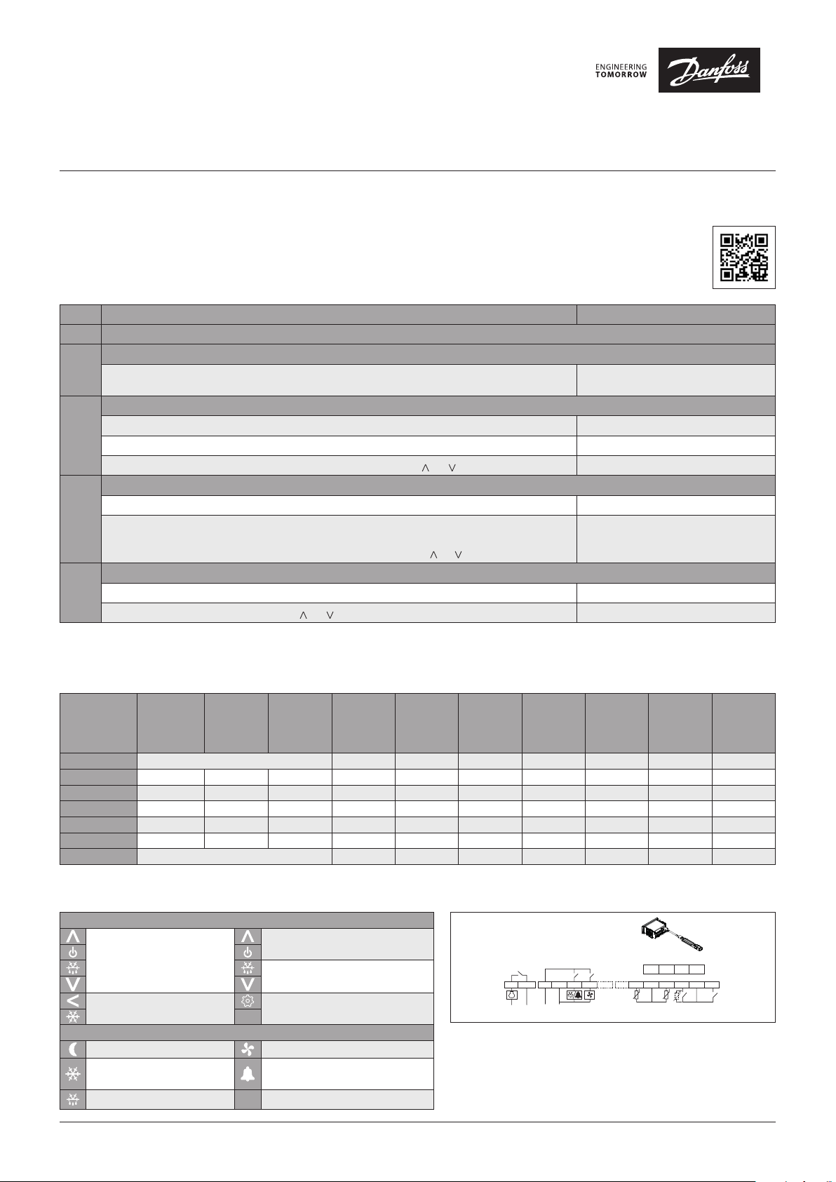
Quick Set-up
STEP Action Screen Display
STEP 1 Wire control, to include power and sensors
Power up control
STEP 2
Energize control
Enter Quick Configuration Menu and Select app
Press ”<” for more than three seconds within one minute of power up to enter Quick Configuration Menu. o61 appears on screen
STEP 3
Press “set” while o61 is on screen AP0 flashes on screen
Select appropriate app using App Selection section below by pressing “ ” or “ ”, then press “set”. o06 appears on screen
Select Sensor
Press “set” while o06 is on screen n10 flashes on screen
STEP 4
If using included sensor, leave default value “n10”. If using another sensor, select using Sensor Resistance
section on opposing page or cycle through steps 2 – 4 changing the sensor type until the temperature reading
on the main screen is accurate. As above, cycle between options by pressing “ ” or “ ” and press “set” to save.
Set Temperature
STEP 5
From main screen, quickly press “set” (1 second). Current temp. setting appears on screen
Cycle to intended temperature by pressing “ ” or “ ” and press “set” to save. Screen returns to main screen
Control turns on, goes through start up,
then shows the current temperature reading
o06 appears on screen, then control resets
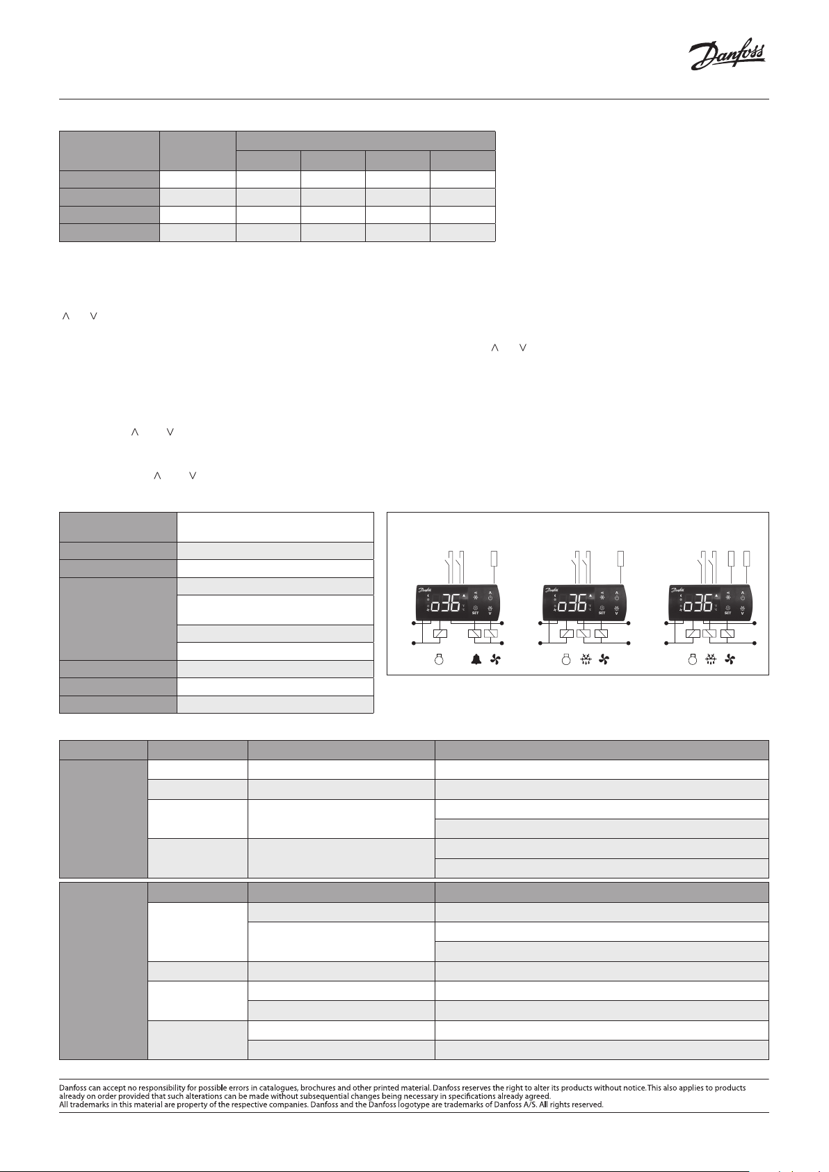
App Selection
Select application based on application and wiring configuration (i.e., refrigeration vs. freezing, and number of temperature sensors). The Typical Wiring
Configurations diagram on the reverse side of this document may be used to assist with selection. All parameters can be modified using the full menu.
Some parameters have min and max set points which may need to be changed for less common configurations.
Control
Application
Code
Application
Defrost
Type*
Defrost
Termination
Sensors
Default
Temp. [°F]
[r00]
Temp. Range
min. / max.
[r02/r03]
AP0 (Default) No preset application — full menu 2 36 -31 / 22 4 6 30 43
AP1 Refrigeration Natural Time 1 39 36 / 43 4 4 30 –
AP2 Refrigeration Electric Time 1 36 32 / 39 4 6 15 –
AP3 Freezing Electric Time 1 -11 -15 / -4 4 6 15 –
AP4 Refrigeration Electric Temp. 2 36 32 / 39 4 6 30 43
AP5 Freezing Electric Temp. 2 -11 -15 / -4 4 6 30 43
AP6 No preset application — simplified menu 2 36 -31 – 122 4 6 30 43
* Hot gas defrost is an option available in full menu (d01).
Key Functions and Display Icons
Key Functions
Press and hold at power up:
FACTORY RESET (“FAC” is
displayed)
Press for one second: BACK
Press and hold: PULL-DOWN
Display Icons
Night mode (Energy saving) Fan running
Compressor running (Flashes
in pull-down mode)
Defrost °C Unit (°C or °F)
SET
Press for one second: UP
Press and hold: ON / OFF
Press for one second: DOWN
Press and hold: DEFROST
Press for one second: TEMP. SETPOINT / OK
Press and hold: MENU
Active alarm
Connection Diagram
– Sair Control sensor
– S5 Defrost (evaporator) sensor
– SC Condenser sensor
– DI1 Digital input – configurable to the functions listed under
menu code o02
– DI2 Digital input – configurable to the functions listed under
menu code o37
© Danfoss | DCS (ADAP-KOOL®) | 2018-11
[°F]
Default Dif.
[°F] [r01]
DO1
12
3L 4N 5678
~~~~
Power supply
DO2 DO3
Defrost
Interval
[hrs]
[d03]
910
SairS5Sc/DI1 DI2
Max.
Defrost
Time [mins]
[d04]
Pr
GND TX RX +5V
15 16 17 18
GND GND
11 12 13 14
Defrost
Termination
Temp. [°F]
[d02]
DKRCE.PD.RL0.A3.02 | 1
Quick Start Guide, ERC 213
ERC 213 — APP 1 ERC 213 — APP 2-3 ERC 213 — APP 4-5
Sensor Resistance: Using an ohmmeter, you can measure resistance of a sensor to identify sensor type or to troubleshoot a potentially faulty sensor.
Sensor Type Code
PTC Ptc 690 761 807 980
PTC 1000 Pt1 931 974 1000 1093
NTC 10000 * n10 70317 40411 29481 10459
NTC 5000 n5 42664 23110 16325 5251
* Included in kit
Resistance [ohm] at Temperature [°F]
0 20 32 75
Common Functions
Adjust Temperature Set Point
From main screen, quickly press “set” (one second). The current temperature setting will appear on screen. Cycle to intended temperature by pressing
“^” or “^” and press “set” to save. The display will return to the main screen.
Adjust Differential
From main screen, press “set” for more than three seconds. Cycle to “r—” submenu by pressing “ ” or “ ” and press “set.” Cycle to “r01” and press “set.” Cycle to
preferred differential setting, and press “set” to save. “r01” will appear on screen. Press “<” twice to return to main screen.
Manual Defrost
From main screen, press defrost for more than three seconds to initiate defrost. The DEFROST icon is shown during defrost. Press defrost key for at least
three seconds to stop manual defrost.
Factory Reset
Press and hold “ ” and “ ” simultaneously at power up.
Unlock Keypad
After 5 minutes of no activity, the keypad will lock if P76 = yes (by default it is set to no). When the keypad is locked any key press shows “LoC”
in the display. Press “ ” and “ ” simultaneously for three seconds to unlock the keyboard. “unl” is displayed for three seconds.
Technical Specifications
Power Supply
Inputs 4 total; 2 analog, 1 analog / digital, 1 digital
080G3411 115V AC 50/60 HZ;
080G3412 230V AC 50/60 Hz
Typical Wiring Configurations
Sair
(Control Sensor)
DI1DI2
DI1DI2
Sair
(Control Sensor)
Sensor Included in Kit NTC 10000
D01 Compressor Relay
115 V (080G3268): 16 FLA / 72 LRA
Output
230 V (080G3269): 10 FLA / 60 LRA
D02 Defrost Relay and / D03 Fan Relay
8A, 2 FLA, 12 LRA
DO1
DO2 DO3 DO1 DO3DO2
115 V AC
230 V AC
Operating Conditions 14 – 131 °F
Storage Conditions -40 – 158 °F
Approvals UL Recognized / NSF
Troubleshooting
Power Supply Code Description Remedy (applicable parameter code in parenthesis)
A01 High temperature alarm Bring down temperature or increase high limit alarm limit (A13)
A02 Low temperature alarm Increase temperature or low temperature alarm limit (A14)
Common Alarm /
Error Codes
E27 Defrost sensor error
E29 Air temperature sensor error
Problem Likely Cause Remedy (applicable parameter number in parenthesis)
Waiting for compressor delay timer
Compressor does
not start
Defrost in progress
Common
Problems /
Resolution
Need additional help with programming, parameters, or error codes? Download Danfoss’ Koolcode app.
Defrost does not start
Wrong temperature
is displayed
Evaporator icing
Controller in pull down mode Check pull-down duration (r96)
Wrong type of sensor selected Verify that correct sensor type is selected (o06)
Sensor installed into incorrect terminals Verify that control sensor is wired into terminals 9 and 10 – 8 is not used
Defrost interval too long Reduce defrost interval (d03)
Defrost time too short Increase max. defrost time (d04)
Verify that defrost sensor is wired into terminals 10 and 11
Verify that correct sensor type is selected (o06)
Verify that control sensor is wired into terminals 9 and 10 – 8 is not used
Verify that correct sensor type is selected
Check compressor minimum off time (
CO2)
Check defrost interval (d03)
Check defrost on demand (temp. initiated defrost) (d19)
115 V AC
230 V AC
DI1DI2
DO1DO3DO2
S5
(Defrost)
Sair
2 | DKRCE.PD.RL0.A3.02
© Danfoss | DCS (ADAP-KOOL®) | 2018-11
FAQ: Types of Manuals and Their Contents
Danfoss ERC 213 Manuals come in various types, each serving a specific purpose to help users effectively operate and maintain their devices. Here are the common types of Danfoss ERC 213 User Guides and the information they typically include:
- User Manuals: Provide comprehensive instructions on how to use the device, including setup, features, and operation. They often include troubleshooting tips, safety information, and maintenance guidelines.
- Service Instructions: Designed for technicians and repair professionals, these manuals offer detailed information on diagnosing and repairing issues with the device. They include schematics, parts lists, and step-by-step repair procedures.
- Installation Guides: Focus on the installation process of the device, providing detailed instructions and diagrams for proper setup. They are essential for ensuring the device is installed correctly and safely.
- Maintenance Manuals: Provide guidance on routine maintenance tasks to keep the device in optimal condition. They cover cleaning procedures, part replacements, and regular servicing tips.
- Quick Start Guides: Offer a concise overview of the essential steps needed to get the device up and running quickly. They are ideal for users who need immediate assistance with basic setup and operation.
Each type of Danfoss ERC 213 instruction is designed to address specific needs, ensuring users have the necessary information to use, maintain, and repair their devices effectively.
Related Instructions for Danfoss ERC 213:
1
AFP Series
Installation manual PDF Manual (@AU19D7), Danfoss AFP Series Controller (Mon 10.2024)
20
627
107
2
BW10 020-090
42
1239
186
3
DEVIreg Smart
28
1292
298
5
TPONE-RF
Manual PDF User Guide (@6R4AS8), Danfoss TPONE-RF Thermostat (Sat 10.2024)
16
1277
269
7
vlt aqua
Design manual User Guide: Danfoss vlt aqua (G7HW12, Upd.Sunday 13-10-2024)
228
345
87
8
AHF 005
Design manual AHF 005 (DC Drives ePDF Manual, #IGR1S7)
156
766
184
9
vlt hvac drive fc 102
84
910
155
10
ECL Comfort 310, P314
Installation manual Danfoss ECL Comfort 310, P314 Guide (Installation manual), @84M593
24
1124
281
Controller Devices by Other Brands:
|
GE N60 Instruction Manual #6B9GM9: N60 Controller Instruction manual 847710A1.CDR 08 Apr 2025 | 644 |
|
|
Milnor MWF27J8 Installation And Service Washer #M34O39 Published Manual Number/ECN: MPIMWF27AE/2019506A 17 Nov 2024 | 110 |
|
|
White WHI-SK20PPHS2 Manual WHI-SK20PPHS2 Manual — PB4JD3 WHI-SK20PPHS2 (2.2 bar Start Up) 31 Mar 2025 | 4 |
|
|
superbrightleds Dream-Color RGB-DC83 Operation & User’s Manual superbrightleds Dream-Color RGB-DC83 Guide (Operation & user’s manual), @Z6I9R7 User Manual for Model 06 Mar 2025 | 4 |
Categories:
Racks & Stands
Recording Equipment
Computer Hardware
Antenna
Water Heater Accessories
Air Conditioner Accessories
Danfoss | DCS (oh) | 2017.09
Quick Start Guide ERC 213
DKRCE.PD.RL0.A1.02 | 520H12295 | 1
Overview The ERC 213 is designed to be an easy, universal replacement control. We encourage users to employ one of five predefined applications that meet the needs of most systems. If users need to modify specific parameters, it should be done after installing the predefined application that most closely meets system needs. For more information, including detailed instructions, error codes, parameters, and more, visit www.danfoss.com/erc or download the Koolcode app from iTunes or Google Play. For a video guide of the quick set-up, visit http://bit.ly/ERC213 or use the QR code located to the right.
STEP Action Screen Display
STEP 1 Wire control, to include power and sensors
STEP 2 Power up control
Energize control Control turns on, goes through start up, then shows the current temperature reading
STEP 3
Enter Quick Configuration Menu and Select app
Press < for more than three seconds within one minute of power up to enter Quick Configuration Menu. o61 appears on screen
Press set while o61 is on screen AP0 flashes on screen
Select appropriate app using App Selection section below by pressing or , then press set. o06 appears on screen
STEP 4
Select Sensor
Press set while o06 is on screen n10 flashes on screen
If using included sensor, leave default value n10. If using another sensor, select using Sensor Resistance section on opposing page or cycle through steps 2 4 changing the sensor type until the temperature reading on the main screen is accurate. As above, cycle between options by pressing or and press set to save.
o06 appears on screen, then control resets
STEP 5
Set Temperature
From main screen, quickly press set (1 second). Current temp. setting appears on screen
Cycle to intended temperature by pressing or and press set to save. Screen returns to main screen
Quick Set-up
Control Application Code
Application Defrost Type*
Defrost Termination Sensors
Default Temp. [F]
[r00]
Temp. Range min. / max.
[F] [r02/r03]
Default Dif. [F] [r01]
Defrost Interval
[hrs] [d03]
Max. Defrost
Time [mins] [d04]
Defrost Termination
Temp. [F] [d02]
AP0 (Default) No preset application — full menu 2 36 -31/22 4 6 30 43
AP1 Refrigeration Natural Time 1 39 36/43 4 4 30
AP2 Refrigeration Electric Time 1 36 32/39 4 6 15
AP3 Freezing Electric Time 1 -11 -15/-4 4 6 15
AP4 Refrigeration Electric Temp. 2 36 32/39 4 6 30 43
AP5 Freezing Electric Temp. 2 -11 -15/-4 4 6 30 43
AP6 No preset application — simplified menu 2 36 -31 122 4 6 30 43
* Hot gas defrost is an option available in full menu (d01).
Key Functions
Press and hold at power up: FACTORY RESET (FAC is displayed)
Press for one second: UP Press and hold: ON/OFF
Press for one second: DOWN Press and hold: DEFROST
Press for one second: BACK Press and hold: PULL-DOWN
Press for one second: TEMP. SETPOINT/OK Press and hold: MENUSET
Display Icons
Night mode (Energy saving) Fan running
Compressor running (Flashes in pull-down mode) Active alarm
Defrost C Unit (C or F)
Key Functions and Display Icons
Sair Control sensor S5 Defrost (evaporator) sensor SC Condenser sensor DI1 Digital input configurable to the functions listed under
menu code o02 DI2 Digital input configurable to the functions listed under
menu code o37
Connection Diagram
DO1
1 2
Sair S5 Sc/DI1 DI2
DO2 DO3
GND GND
Programming key EKA 183B (080G9741)
3L 4N 5 6 7 8 9 10
15 16 17 18
11 12 13 14
~~~ ~ Power supply
(according to the product code number)
GND TX RX +5V
App Selection Select application based on application and wiring configuration (i.e., refrigeration vs. freezing, and number of temperature sensors). The Typical Wiring Configurations diagram on the reverse side of this document may be used to assist with selection. All parameters can be modified using the full menu. Some parameters have min and max set points which may need to be changed for less common configurations.
Danfoss | DCS (oh) | 2017.09
Quick Start Guide, ERC 213
2 | 520H12295 | DKRCE.PD.RL0.A1.02
Sensor Resistance: Using an ohmmeter, you can measure resistance of a sensor to identify sensor type or to troubleshoot a potentially faulty sensor.
Sensor Type Code Resistance [ohm] at Temperature [F]
0 20 32 75
PTC Ptc 690 761 807 980
PTC 1000 Pt1 931 974 1000 1093
NTC 10000 * n10 70317 40411 29481 10459
NTC 5000 n5 42664 23110 16325 5251
* Included in kit
Common Functions Adjust Temperature Set Point From main screen, quickly press set (one second). The current temperature setting will appear on screen. Cycle to intended temperature by pressing ^ or ^ and press set to save. The display will return to the main screen. Adjust Differential From main screen, press set for more than three seconds. Cycle to r— submenu by pressing or and press set. Cycle to r01 and press set. Cycle to preferred differential setting, and press set to save. r01 will appear on screen. Press < twice to return to main screen. Manual Defrost From main screen, press defrost for more than three seconds to initiate defrost. The DEFROST icon is shown during defrost. Press defrost key for at least three seconds to stop manual defrost. Factory Reset Press and hold and simultaneously at power up. Unlock Keypad After 5 minutes of no activity, the keypad will lock if P76 = yes (by default it is set to no). When the keypad is locked any key press shows LoC in the display. Press and simultaneously for three seconds to unlock the keyboard. unl is displayed for three seconds.
Typical Wiring Configurations
Sair (Control Sensor)DI1 DI2
Sair (Control Sensor)DI1 DI2
Sair (Control Sensor)DI1 DI2
S5 (Defrost)
DO1
115 V AC 230 V AC
115 V AC 230 V AC
115 V AC 230 V AC
DO2 DO3 DO1 DO3DO2 DO1 DO3DO2
ERC 213 — APP 1 ERC 213 — APP 2-3 ERC 213 — APP 4-5
Troubleshooting
Power Supply Code Description Remedy (applicable parameter code in parenthesis)
Common Alarm / Error Codes
A01 High temperature alarm Bring down temperature or increase high limit alarm limit (A13)
A02 Low temperature alarm Increase temperature or low temperature alarm limit (A14)
E27 Defrost sensor error Verify that defrost sensor is wired into terminals 10 and 11
Verify that correct sensor type is selected (o06)
E29 Air temperature sensor error Verify that control sensor is wired into terminals 9 and 10 8 is not used
Verify that correct sensor type is selected
Common Problems / Resolution
Problem Likely Cause Remedy (applicable parameter number in parenthesis)
Compressor does not start
Waiting for compressor delay timer Check compressor minimum off time (CO2)
Defrost in progress Check defrost interval (d03)
Check defrost on demand (temp. initiated defrost) (d19)
Defrost does not start Controller in pull down mode Check pull-down duration (r96)
Wrong temperature is displayed
Wrong type of sensor selected Verify that correct sensor type is selected (o06)
Sensor installed into incorrect terminals Verify that control sensor is wired into terminals 9 and 10 8 is not used
Evaporator icing Defrost interval too long Reduce defrost interval (d03)
Defrost time too short Increase max. defrost time (d04)
Need additional help with programming, parameters, or error codes? Download Danfoss Koolcode app.
Technical Specifications
Power Supply 080G3268 115V AC 50/60 HZ; 080G3269 230V AC 50/60 Hz
Inputs 4 total; 2 analog, 1 analog / digital, 1 digital
Sensor Included in Kit NTC 10000
Output
D01 Compressor Relay
115 V (080G3268): 16 FLA / 72 LRA 230 V (080G3269): 10 FLA / 60 LRA
D02 Defrost Relay and / D03 Fan Relay
8A, 2 FLA, 12 LRA
Operating Conditions 14 131 F
Storage Conditions -40 158 F
Approvals UL Recognized / NSF
Danfoss | DCS (oh) | 2017.09 DKRCE.PD.RL0.A1.02 | 520H12295 | 3
Quick Start Guide, ERC 213
Parameter Name Menu Code Unit Min. Value Max. Value Default Value Value
Predefined applications o61 App0 App0
Sensor type o06 n10 n10
Temperature Setpoint r00 C -100 200 2 2
Differential r01 K 0.1 20 2 2.7
Min. set point limit r02 C -100 200 -35 -35
Max. set point limit r03 C -100 200 50 50
Display offset r04 K -10 10 0 0
Display Unit r05 C F
Calibration of Sair r09 K -20 20 0 0
Night Set back r13 K -50 50 0 0
Offset reference displacement r40 C -50 20 0 0
Pull down duration r96 min.. 0 960 0 0
Pull down temp limit r97 C -100 200 0 0
Alarm delay — Normal conditions A03 min. 0 240 30 30
Alarm delay — pulldown / startup / def A12 min. 0 240 60 60
High temp alarm A13 C -100 200 8 8
Low temp alarm A14 C -100 200 -30 -30
DI1 delay A27 min. 0 240 30 30
DI2 delay A28 min. 0 240 30 30
Condenser High temp alarm A37 C 0 200 80 80
Condenser High block limit A54 C 0 200 85 85
Voltage protection A72 No No
Min. cut-in voltage A73 V 0 270 0 0
Min. cut-out voltage A74 V 0 270 0 0
Max. voltage A75 V 0 270 270 270
Defrost Method d01 Electric Electric
Defrost stop temperature d02 C 0 50 6 6.5
Defrost Interval d03 hour 0 240 8 6
Max. defrost Time d04 min. 0 480 30 30
Defrost delay at power up d05 min. 0 240 0 0
Drip delay d06 min. 0 60 0 0
Fan delay after defrost d07 min. 0 60 0 0
Fan start temp after defrost d08 C -50 0 -5 -5
Fan ON during defrost d09 On On
Defrost stop sensor d10 None None
Comp accumulated runtime d18 hour 0 96 0 0
Defrost on demand d19 K 0 20 20 20
Defrost delay after pulldown d30 min. 0 960 0 0
Fan at compressor cutout F01 FFC FAo
Fan stop evaporator temp F04 C -50 50 50 50
Fan ON time F07 min. 0 15 2 2
Fan OFF time F08 min. 0 15 2 2
Parameter sheet
Danfoss | DCS (oh) | 2017.09
Quick Start Guide, ERC 213
4 | 520H12295 | DKRCE.PD.RL0.A1.02
Parameter Name Menu Code Unit Min. Value Max. Value Default Value Value
Compressor min. ON time C01 min. 0 30 0 0
Compressor min. OFF time C02 min. 0 30 2 2
Comp OFF delay at open door C04 min. 0 15 0 0
Zero crossing C70 yes yes
Delay of outputs at startup o01 sec 0 600 5 5
DI1 configuration o02 Off Off
Serial address o03 0 247 0 0
Password o05 0 999 0 0
Display Resolution o15 0.1 1
Relay 1 counter o23 0
Relay 2 counter o24 0
Relay 3 counter o25 0
DI2 configuration o37 Off Off
Display during defrost o91 -d- -d-
DO2 Config o71 def def
DI1 polarity P73 no no
DI2 polarity P74 no no
Invert alarm relay P75 Normal Normal
Keyboard lock P76 No No
Main switch r12 Off On
Controller status u00 S25 S20
Air temperature (Sair) u01 C 321
Present regulation reference u02 0
Evaporator temperature (S5) u09 C 0
DI1 status u10 Off Off
Night mode u13 Off Off
DI2 status u37 Off Off
Condenser temperature (Sc) U09 0
Compressor relay status u58 Off Off
Fan relay status u59 Off On
Defrost relay status u60 Off Off
Firmware version u80 4.16
Database version 4.02
Order No Low 3502
Air temperature sensor(Sair) error E29 Off On
Defrost sensor (S5) error E27 Off Off
Condensor sensor(Sc) error E30 Off Off
High temperature alarm A01 Off Off
Low temperature alarm A02 Off Off
High voltage alarm A99 Off Off
Low voltage alarm AA1 Off Off
High condenser temperature alarm A61 0 Off Off
Door alarm A0