
Содержание
- Ремонт райдеров и садовых мини-тракторов Cub Cadet (Куб Кадет)
- Модельный ряд миии-тракторов, райдеров Cub Cadet принимаемых в ремонт
- Стоимость ремонта миии-тракторов, райдеров Cub Cadet*
- Запчасти и аксессуары для миии-тракторов, райдеров Cub Cadet
- Типичные поломки миии-тракторов, райдеров Cub Cadet
- *Примечания
- Инструкция для мини камеры MD80 для видеонаблюдения
- Operator’s Manuals
- Don’t Know Your Model Number
- About Us
- Owner’s Center
- Independent Dealers
- Customer Service
- We are experiencing high call volumes.
- Инструкция на русском языке к мини видео камере Mini DV G100
- Описание:
- 1. Органы управления
- 2. Зарядка
- 3. Режимы видеозаписи
- 4. Просмотр видео
- 5. Режим Web-камеры
- 6. Установка даты и времени
- 7. Общие характеристики
- 8. Комплектация
Ремонт райдеров и садовых мини-тракторов Cub Cadet (Куб Кадет)
Модельный ряд миии-тракторов, райдеров Cub Cadet принимаемых в ремонт
Мы выполняем ремонт следующих моделей райдеров, кросс-муверов и садовых мини-тракторов, газонокосилок с сиденьем Куб Кадет:
- Модели садовых мини-тракторов Куб Кадет
- ремонт мини-трактора Cub Cadet LT2 NS96
- ремонт мини-трактора Cub Cadet LT1 NR92
- ремонт мини-трактора Cub Cadet LT2 OS107 (SPECIAL)
- ремонт мини-трактора Cub Cadet LT2 NR92
- ремонт мини-трактора Cub Cadet CC 714 TE
- ремонт мини-трактора Cub Cadet LT2 OR 105 (SPECIAL)
- ремонт мини-трактора Cub Cadet CC 917 AN
- ремонт мини-трактора Cub Cadet CC 917 HE
- ремонт мини-трактора Cub Cadet XT1 OS96
- ремонт мини-трактора Cub Cadet CC 917 AE
- ремонт мини-трактора Cub Cadet LT3 PR105
- ремонт мини-трактора Cub Cadet XT1 OR95
- ремонт мини-трактора Cub Cadet XT1 OR106
- ремонт мини-трактора Cub Cadet XT2 PS 107
- ремонт мини-трактора Cub Cadet XT2 PS 117
- ремонт мини-трактора Cub Cadet XT2 QS117
- ремонт мини-трактора Cub Cadet XT2 PR95
- ремонт мини-трактора Cub Cadet XT2 QR106
- ремонт мини-трактора Cub Cadet CC 1022 KHI (KOHLER)
- ремонт мини-трактора Cub Cadet XT3 QS127
- ремонт мини-трактора Cub Cadet XT3 QR95
- ремонт мини-трактора Cub Cadet XT3 QS137
- Модели садовых райдер (минирайдер) Куб Кадет
- ремонт минирайдера Cub Cadet Minirider CC 114 TD
- ремонт минирайдера Cub Cadet LR1 NR76
- ремонт минирайдера Cub Cadet LR2 NR76
- ремонт минирайдера Cub Cadet RZT-42
- ремонт минирайдера Cub Cadet XZ2 107
- ремонт минирайдера Cub Cadet RZT-S 42
- ремонт минирайдера Cub Cadet RZT-S 46
- ремонт минирайдера Cub Cadet XZ1 127
- ремонт минирайдера Cub Cadet XZ1 137
- ремонт минирайдера RZT-S 50
- ремонт минирайдера Z FORCE SZ-48
- ремонт минирайдера XZ3 122
- ремонт минирайдера Z1 137
- ремонт минирайдера Z5 152
*Если Вы не нашли в приведённом списке Вашей модели, не огорчайтесь мы выполняем ремонт практических всех миии-тракторов, райдеров Cub Cadet. Просто оставьте заявку на ремонт на сайте или позвоните нам По телефону – наши специалисты сц «Серви» ответят на любые Ваши вопросы.
Стоимость ремонта миии-тракторов, райдеров Cub Cadet*
Окончательная стоимость необходимого ремонта миии-тракторов, райдеров Cub Cadet во многом зависит от цен на запасные части и согласовывается с заказчиком по телефону, после проведенной мастером диагностики.
| Наименование работ по ремонту миии-тракторов, райдеров Cub Cadet | Стоимость услуг, руб.* |
|---|---|
| Регулировка карбюратора | 1900 руб. |
| Замена стартера | 700 руб. |
| Ремонт стартера | 900-1300 руб. |
| Замена свечи зажигания | 100 руб. |
| Замена сцепления в сборе | 1200 руб. |
| Замена редуктора привода колес | 2500 руб. |
| Замена карбюратора | 1700 руб. |
| Замена катушки зажигания | 900 руб. |
| Регулировка зажигания | 700 руб. |
| Замена приводного ремня | 1300 руб. |
| Замена троса управления газом | 1800 руб. |
| Регулировка троса управления газом | 900 руб. |
| Замена воздушного фильтра | 100 руб. |
| Комплексное техническое обслуживание миии-тракторов, райдеров Cub Cadet (работы) | от 4500 руб. (от модели) |
Запчасти и аксессуары для миии-тракторов, райдеров Cub Cadet
В нашем сервисном центре Вы сможете заказать\ приобрести запасные части и аксессуары для миии-тракторов, райдеров Cub Cadet. Мы работаем по пред-заказу запчастей. Наиболее распространённые позиции всегда есть на нашем складе! Уникальные запчасти и аксессуары мы заказываем непосредственно у производителей без наценок, срок их доставки варьируется в интервале от 5 до 30 рабочих дней.
Наличие, комплектность и стоимость необходимых запчастей без проблем можно уточнить, позвонив нам По телефону или оставив заявку на запчасти на сайте.
Типичные поломки миии-тракторов, райдеров Cub Cadet
Согласно статистике Servy основными неисправностями* при работе с мотопомпами Куб Кадет являются:
- Не заводится, отсутствует искрообразование у миии-тракторов, райдеров Cub Cadet — причины: неисправна свеча зажигания, неисправна катушка зажигания (магнето), повреждение деталей ручного стартера, засор топливной системы, износ цилиндро-поршневой группы;
- Не едетмиии-трактор, райдер Cub Cadet, возможные причины: изношены детали узла привода хода (зубчатые колеса), износ ремня привода хода, не отрегулирован/поврежден трос управления приводом хода;
- Не вращаются ножи, деки у миии-тракторов, райдеров Cub Cadet, основные причины: износ деталей механизма привода, износ приводного ремня;
- Глохнет миии-тракторов, райдеров Cub Cadet — причины: засор топливной системы (отсутствует подача топлива), износ цилиндро-поршневой группы, разрегулирован карбюратор, засор воздушного фильтра.
Эти дефекты являются типичными у миии-тракторов, райдеров Cub Cadet: одни встречаются чаще, другие реже. И не редко они происходят из-за самых простых причин: ненадлежащей эксплуатация (не проводится техническое обслуживание), несвоевременная чистка навесного оборудования, использование не качественной бензо-смеси (масло и бензин) или не рекомендованного топлива, несвоевременная замена масла в двигателе мини-трактора, использование не рекомендованного и самодельного навесного оборудования, многочасовая бесперебойная работа райдера, механические повреждения агрегатов устройства: деки, колес, тросов управления, ремней. Одни из них встречаются чаще, иные реже; но все они легко поддаются ремонту специалистами сервисного центра «Servy» в Москве.
Просто оставьте заявку на ремонт миии-тракторов, райдеров Cub Cadet на сайте или позвоните нам По телефону – наши специалисты сц «Серви» ответят на любые Ваши вопросы.
*Примечания
• Точные сроки ремонта всегда указываются только после диагностики. • Стоимость услуг «Серви» носят ознакомительный характер и могут быть изменены после проведения диагностики Вашей техники. С каждым клиентом мы работаем индивидуально и детальный расчет цены ремонта производится в соответствии с уровнем сложности поломки конкретного вида оборудования. • Запчасти, которые мы используем в ремонте, оплачиваются отдельно. • Расчет на основе данных из клиентской базы «Servy».
Источник
Инструкция для мини камеры MD80 для видеонаблюдения
Мини камера MD80 для видеонаблюдения является универсальным гаджетом, который можно использовать в целях видеонаблюдения за объектами, например, мелкой торговли или за маленьким ребенком в комнате.
Возможность записывать звук позволяет использовать устройство в качестве диктофона. Компактные размеры устройства также порадуют пользователя, поскольку камера запросто поместится даже в карманах джинс.
Характеристики:
- Материал: пластмасса;
- Цветкорпуса: черный;
- Матрица: цветная CMOS, 2 МП;
- Угол обзора: 80°;
- Минимальное освещение для работы: 1 Люкс;
- Аккумулятор: 260 mAh;
- Продолжительность работы: до полутора часов;
- Рабочая температура: -10°- +50° С;
- Память: MicroSD до 16 Гб;
- Видео разрешение: 640×480 px, 30 кадров/сек;
- Формат записи видео: AVI;
- Место на карте памяти: 2,2 Гб — 1 час;
- Вес: 50 гр;
- Размеры: 5,5 см * 2 см * 1,8 см;
- В комплекте: видеокамера MD80, клипса с зажимом, кабель USB, клипса с креплением, шнурок для переноски.
Работа с устройством:
Перед первым использованием обязательно зарядите аккумулятор по максимуму.
Чтобы начать зарядку мини камеры MD80, подключите ее к USB порту компьютера или другого устройства, к адаптеру питания от сети 220В (в комплект не входит) или к прикуривателю в авто.
В режиме зарядки синий светодиод будет информировать о процессе зарядки. Когда зарядка завершится, будет постоянно светиться красный диод.
Перед тем, как начинать снимать видео, установите в устройство карту памяти. Если карты нет в гаджете, то синий индикатор будет быстро мигать, информируя вас о проблеме.
Чтобы включить устройство, нажмите на кнопку питания. Чтобы выключить камеру, нажмите на кнопку питания еще раз.
Чтобы начать записывать видео, камера должна быть включена. Нажмите кнопку Старт/Стоп — запись начнется автоматически. Снимать можно и при подключенной камере к сети питания. Чтобы остановить запись, нажмите кнопку Старт/Стоп. Запись будет автоматически сохранена на карту памяти в формате AVI.
Запись с датчиком звука:
Нажмите кнопку Mode во время работы камеры. Когда появляется источник шума выше 60 Дб, автоматически начинается запись.
Запись автоматически прекращается через две минуты записи в этом режиме.
Начать запись в ручном режиме можно нажатием на кнопку Старт/Стоп.
Выйти из режима можно нажав на кнопку Mode.
Работа в режиме ВЕБ-камеры:
Перед началом работы в этом режиме включите камеру и подключите ее к ПК через USB шнур. Гаджет автоматически определиться как стандартная ВЕБ-камера.
Установка времени и даты:
Подключите гаджет к компьютеру. Чтобы задать время и дату, нужно создать текстовый файл с названием TAG.txt в корневом каталоге карты памяти. В файле прописать данные в следующем порядке: ГГГГ-ММ-ДД ЧЧ:ММ:СС.
Чтобы активировать данные, выключите и вновь включите камеру.
Источник
Operator’s Manuals
Did you misplace your lawn mower manual or operator’s manual for another MTD product? Not a problem. You can download a copy of your Operator’s Manual for free right here! Your model number is required to find your mower owner’s manual. A serial number will get you an exact match. We can also help you find your model number if you’re not sure where to look.
Your model number is required to find your owners manual. A serial number will get you an exact match.
Don’t Know Your Model Number
Knowing your outdoor power equipment’s model number and serial number will ensure that you find the correct operator’s manual for your equipment
About Us
- Our Story
- How-To Articles
- Built In America
- Special Offers
- News
- Financing
- Our Engine Advantage
Owner’s Center
- Product Recalls
- Operator’s Manuals
- Product Registration
- Service Locator
- Find a Part
- Lookup Parts via Diagram
- Cub Cadet Gear
Independent Dealers
- Find a Dealer
- Dealer Delivery or Pick-Up
- Become a Dealer
- Dealer Advantage
Customer Service
- (877) 428 2349
- Track Order
- My Account
- FAQs & Support
- Product Safety
We are experiencing high call volumes.
We are available Monday — Friday, 8:30 am — 5:00 pm EST. To speak with an agent, you might experience longer than normal hold times. We apologize for the inconvenience.
Start a live chat
Helpful links.
- Find a part
- Find a product manual
- Find a service center
- Find an article
- Track my order
Global Sites
- Canada
- Europe
- Australia
- China
TOP
If you experience any problems accessing this website, please call us at 1-877-428-2349 for assistance.
Engine Disclaimer: The engine horsepower information is provided by the engine manufacturer to be used for comparison purposes only. See your local Cub Cadet Dealer for warranty details.Pricing Disclaimer: Posted price is in USD Dollars and is manufacturer’s suggested sale price. Models and pricing may vary by location. Taxes, freight, set-up and delivery not included. Optional equipment, accessories and attachments sold separately. See your retailer for details. Image Disclaimer: Products may vary from depicted model image in design, required attachments, safety features and non-functional appearance, and may not reflect dealer inventory or unit specifications. Specifications Disclaimer: Specifications subject to change without notice. Images may not reflect retailer inventory and/or unit specifications. Operator’s Manual Disclaimer: The operator’s manual posted is for general information and use. To ensure the download of the operator’s manual specific to your unit, we require a model and serial number. Speed Disclaimer: Actual vehicle speed varies based on load, use and environmental conditions. Battery Disclaimer: Battery and battery powered product performance varies with load, use and environmental conditions. Software Disclaimer: Software available on Company websites is provided on an «as is» basis without any warranty of any kind, either express or implied. The download and use of any software is done at the user’s own risk. Professional Products: Cub Cadet commercial products are intended for professional use. UTV: Cub Cadet Utility Vehicles (UTV) are intended for off-road use by adults only. Please see the operator’s manual and the warning labels posted on the vehicle itself for more details. Email disclaimer: Sign up to receive communication on services, products and special offers. You may unsubscribe at any time. Please refer to our Privacy Policy.
*When compared to the same engine without IntelliPower™ feature, improvements vary depending on engine models and specific operating conditions.
*A-weighted sound level per ISO-5395-1, 95% confidence comparing XT1 Enduro Series LT42, Ultima ZT1 42 and CC30.*
Источник
Инструкция на русском языке к мини видео камере Mini DV G100
Инструкция по эксплуатации на русском языке к мини видео камере Mini DV G100.
Описание:
1. Органы управления
2. Зарядка
3. Режимы видеозаписи
4. Просмотр видео
5. Режим Web-камеры
6. Установка даты и времени
7. Общие характеристики
8. Комплектация
1. Органы управления
2. Зарядка
Перед первым использованием необходимо полностью зарядить аккумулятор Мини видеокамеры. Сделать это возможно, подключив Мини камеру, не включая её, к USB порту ПК при помощи специального USB-провода, который входит в комплект поставки. Так же можно зарядить камеру, подключив её к адаптеру питания от сети 220В или от автомобильного прикуривателя.
В режиме зарядки красный индикатор будет гореть постоянно. Как только аккумулятор зарядится, красный индикатор погаснет. При зарядке от порта USB, индикатор может продолжить гореть даже в случае полной зарядки батареи. Для полной зарядки аккумулятора достаточно 2-3 часов.
При полной разрядке аккумулятора, синий индикатор начнёт медленно мигать и через 2 минуты камера отключится.
3. Режимы видеозаписи
Вставьте карту памяти Micro SD в слот Мини видеокамеры. Зеленый индикатор будет мигать, если карта памяти будет отсутствовать.
Включите Мини камеру, переключив кнопку Power в режим ON, а кнопку Mode в режим M1. Для начала записи видео нажмите однократно кнопку записи — зелёный индикатор начнёт медленно мигать. Чтобы остановить запись, нажмите ещё раз кнопку записи. Файл сохранится в формате AVI.
Запись по датчику движения
Включите Мини камеру, переключив кнопку Power в режим ON, а кнопку Mode в режим M2. Камера перейдёт в режим ожидания, а синий индикатор будет очень медленно мигать. Видеокамера автоматически начнет запись, при изменении изображения в поле зрения объектива миникамеры. Индикатор начнёт гореть зелёным цветом. Если во время записи изображение не меняется в течение 20 секунд, камера автоматически вернётся в режим ожидания.
4. Просмотр видео
Для просмотра записанных видео роликов, необходимо подключить Мини камеру к ПК при помощи USB-кабеля, который входит в комплект поставки. После чего переведите кнопку Power в режим ON. Так же возможно использование карт-ридера для считывания файлов с карты памяти.
5. Режим Web-камеры
Для использования Мини камеры в качестве Web-камеры необходимо установить драйверы. Скачать их Вы можете на нашем сайте на странице Мини видеокамеры G100, найдя файл “Драйверы”.
Подключите устройство к ПК, при помощи USB-кабеля. Включите Мини камеру, переключив кнопку Power в режим ON, а кнопку Mode в режим M2. Видеокамера определится, как стандартная Web-камера.
6. Установка даты и времени
Подключите устройство к ПК при помощи USB-кабеля. Для установки точного времени на Мини камере, необходимо создать текстовый файл с названием time.txt в корневом каталоге карты памяти, со следующим содержанием:
Например: 2014-02-27 18:00:04
После создания файла, сохраните его и отключите Видеокамеру от ПК. Теперь будет указываться точное время.
7. Общие характеристики
- Температура эксплуатации: -10°C + 60°C
- Влажность окружающей среды: 15-85%
- Разрешение: Цветная CMOS, 2 мегапикселя
- Угол обзора: 72°
- Освещенность съемки: 1 люкс (минимум)
- Емкость встроенной батареи: 250 mAh
- Продолжительность работы: 1.5 ч.
- Время заряда: 2-3 ч.
- Память: Micro SD до 64 Гб
- Разрешение видео: 640х480@30 кадров/сек.
- Формат видео: AVI
- Габариты: 54х20х15 мм.
- Вес: 40 гр.
8. Комплектация
- Мини видеокамера G100
- Кабель USB — miniUSB
- Магнитный кронштейн
- Комплект креплений (двусторонний скотч, шурупы)
- Цепочка на шею
- Мешочек из бархатной ткани
Благодарим Вас, что стали нашим клиентом!
Источник

- Все о товаре
- Отзывы(0)
CADET logic — Свободно программруемый контроллер для дискретного управления различными инженерными системами
Область применения
- Управление различными технологическими процессами и установками по дискретной логике;
- Организация систем сигнализации в схемах автоматизации технологических процессов.
Функции
- Обработка входных сигналов по записанной пользователем логике и управление выходами контроллера на основании этой логики;
- Сигнализация состояний входов и выходов;
- Интерфейс RS-485* (протоколы MODBUS-RTU и ЮНИВЕРС).
Технические характеристики
| Напряжение питания | ~24 B, 50 Гц или =24 В | |
| Потребляемая мощность, не более | 5 Вт | |
| Вход для программирования | USB | |
| Программирование | «Конфигуратор CDL» по стандарту IEC 61131-3.1 Ladder Diagram («Лестничные диаграммы») | |
| Входы | пороговые (0-10) В или дискретные с внутренним источником питания |
12 шт |
| Выходы | дискретные беспотенциальные 6А, ~220 В | 8 шт. |
| Интерфейс | RS-485 | |
| Корпус | степень защиты IP 20 | |
| Подключение | провод, сечением не более 1 мм² |
Схема подключения

Габаритные размеры


8¼”
21cm
The Perfectoe
Front
18”
45.7cm
14½”
36.8cm
Top
The Perfectoe
OWNER’S GUIDE
Features & Benefits
•
Thermal Safeguard
•
High temperature manual reset:
turns off heater if normal operating
temperatures are exceeded
3½”
8.9cm
¼”
.6cm
•
Rugged steel-finned element
•
Ideal for bathrooms and kitchens
•
Low profile for rooms with limited space
•
Two-year extended warranty
•
Single pole or double pole field mount
thermostat kit available
•
Black or white powder coat paint for
a durable finish
MODELS
The Perfectoe
UC072
UC102
UC101
Side
TOOLS REQUIRED:
Phillips Screwdriver
Straight Screwdriver
Wire Strippers
Utility Knife
1
/2” Wood Screws
(2) 1
(3) Insulated Wire Connectors
(1) Strain Relief Connector
IMPORTANT INSTRUCTIONS
WARNING
Turn the electrical power off at the electrical
panel board (circuit breaker or fuse box) and
lock or tag the panel board door to prevent
someone from turning on power while you are
working on the heater. Failure to do so could
result in serious electrical shock, burns, or
possible death.
1. Read all instructions before using this heater.
2. Read all information labels. Verify that the electrical supply
wires are the same voltage as the heater.
3. All electrical work and materials must comply with the
National Electric Code (NEC), the Occupational Safety and
Health Act (OSHA), and all state and local codes.
4. Connect the grounding pigtail (copper wire) provided in the
wall can to the supply ground wire.
5. If you need to install a new circuit or need additional wiring
information, consult a qualified electrician.
6. Protect electrical supply from kinks, sharp objects, oil,
grease, hot surfaces or chemicals.
7. WARNING
Overheating or fire may occur. DO NOT install the heater in
a floor, behind doors, or outdoors.
* For installations above 7000 feet, highest
wattage recommended is 750 watts.
8. WARNING
Fire or explosion may occur. Heater has hot and arcing or
sparking parts inside. Do not install heater in any area
where combustible vapors, gases, liquids, or excessive lint
or dust are present.
9. WARNING
Burn Hazard. This heater is hot when in use. To avoid burns,
do not let bare skin touch hot surfaces. Use extreme caution
when any heater is used by or near children or invalids and
whenever the heater is left operating unattended.
10. WARNING
Risk of Electrical Shock. Keep all foreign objects out of
heater. Do not operate after heater malfunctions or has
been dropped or damaged in any manner.
11. WARNING
Risk of Fire. Do not block heater. Heater must be kept clear
of all obstructions: a minimum of 3 feet in front, 6 inches on
both sides. Heaters must be kept clean of excessive lint, dirt
and debris. (See Maintenance Instructions).
12. Use this heater only as described in this manual. Any other
use not recommended by the manufacturer may cause fire,
electrical shock, or injury to persons.
SAVE THESE INSTRUCTIONS
www.cadetco.com Tel: 360-693-2505 P.O. Box 1675 Vancouver, WA 98668-1675
READ ALL
INSTRUCTIONS
AND SAFETY
INFORMATION
Installation Instructions
Part One
PLACEMENT: Read IMPORTANT INSTRUCTIONS for important safety requirements. For best results,
install heater beneath a cabinet in the toe kick area. Install the Perfectoe (Model UC) horizontally. Do not
install the UC heater in the floor. Headers and bracing are not necessary. Heater must be installed per the
directions indicated on the lid. See clearance requirements for additional placement instructions. Install
at least 6” from the inside corner and/or vertical adjacent surfaces.
CONTROLS: A thermostat is required. A Cadet electronic thermostat is recommended for ultimate control
and comfort. Optional single or double pole field mount thermostat kits are also available.
IMPORTANT!
It is extremely
important that
you verify the
electrical supply
wires are the same
voltage as the
heater (i.e. 120 volt
heater to 120 volt
power supply and
240 volt heater to
240 volt power
supply). If
replacing an
existing heater,
check the labels of
the old heater and
replace using the
same voltage.
Hooking a 240 volt
heater to a 120 volt
power supply will
drastically reduce
the heater’s
output. Hooking a
120 volt heater to a
240 volt power
supply will destroy
the heater.
Connecting your
heater to an
incompatible power
supply will void the
warranty.
STEP 1 Turn the Electrical Power OFF
Turn the electrical power off at the electrical
panel board (circuit breaker or fuse box) and lock
or tag the panel board door to prevent someone
from turning on power while you are working
on the heater.
STEP 2 Determine Area of Installation
The UC Series heater REQUIRES A MINIMUM
distance of 6 inches from adjacent surfaces
(See Figure 1). However, Cadet RECOMMENDS
12 inches from all adjacent surfaces for longer
and cleaner performance. Heaters must be
spaced at least 3 feet apart.
For installation in an existing wall/cabinet, cut
a rough opening 14½ inches wide by 3½ inches
high. Opening must be 8½ inches deep and
6 inches from adjacent wall.
Figure 1
WARNING! Vinyl floor manufacturers warn
that some vinyl may discolor from temperatures
in excess of 110° F. See your vinyl floor
manufacturer for temperature specifications
for your vinyl floor covering.
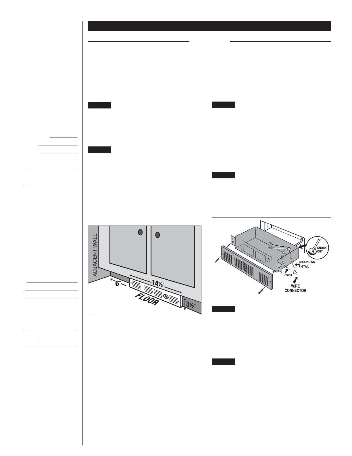
STEP 3 Route Supply Wires
For wall thermostat applications, route supply wire
from circuit breaker to thermostat to rough
opening. For models with an optional field mount
thermostat kit, route supply wire from circuit
breaker to rough opening. Allow enough wire to
extend 12 inches beyond the opening. Place heater
lid aside. Remove the knockout and attach the
supply wire with a strain relief connector, leaving
6 inches wire lead for later use (See Figure 2).
STEP 4 Connect Supply Wires
Connect the supply ground wire to the green
grounding pigtail provided (See Figure 2). Connect
each supply wire to one heater wire with wire
connectors. Note: All wire connections must be
made inside the heater.
Figure 2
STEP 5 Mount the Heater
Reinstall heater lid and attach using four screws
provided. Slide heater into opening. Fasten heater
to cabinet with screws (not provided) going
through the lower holes located on the flanges.
Fasten grill to heater with screws provided going
through the upper holes located on the flanges.
STEP 6 Turn the Electrical Power ON
Turn the electrical power back on at the electrical
panel board (circuit breaker or fuse box).
2

Operation and Maintenance
Part Two
How to operate your heater
1. Once installation in complete and power has
been restored turn the thermostat knob fully
clockwise.
2. When the room reaches your comfort level, turn
the thermostat knob counterclockwise until the
heater turns off. The heater will automatically
cycle around this preset temperature.
3. To reduce the room temperature, turn the
knob counterclockwise. To increase the room
temperature, turn the knob clockwise.
Maintenance
As needed, or every six months minimum.
1. WARNING! Before removing grill, turn the
electrical power off at the electrical panel
board (circuit breaker or fuse box). Lock or tag
the panel board door to prevent someone from
accidentally turning the power on while you
are working on the heater. Failure to do so
could result in serious electrical shock, burns,
or possible death.
2. It is important that you verify power has been
turned off and no power is going to the heater
before proceeding. Circuit breakers are often
not marked correctly and turning the wrong
breaker off could mean electricity is flowing to
the heater, even if the heater does not appear
to be working. If you are uncomfortable working
with electrical appliances, unable to follow
these guidelines, or do not have the necessary
equipment, consult a qualified electrician.
3. Once you verify the power has been turned
off correctly, proceed to the next step.
4. Remove thermostat knob, if equipped.
Remove the screws and take off grill.
5. Wash grill with hot, soapy water and dry
immediately.
6. If present, remove the screws securing the
heater assembly to the opening, then pull
heater out of opening.
7. Remove the four screws securing the lid to the
top of the heater assembly, remove lid.
8. Thoroughly vacuum accumulated dust, lint
or other debris from blower wheel and heater
outlet. Important: Be careful not to damage
the blower wheel, and do not allow the blower
wheel to spin freely when vacuuming.
9. Install lid and slide heater assembly back into
opening. Secure heater assembly to opening,
then install grill and thermostat knob (if equipped).
10. Restore power to heater at circuit breaker
panel or fuse box, then test heater operation
by turning thermostat on and/or adjusting
to a higher temperature.
About the Manual Reset Temperature Limit Control
The heater is protected by a temperature-limit
control. The manual reset temperature limit control
is designed to open the heater circuit when
excessive operating temperatures are detected.
The problem must be assessed and the limit must
be reset to resume operation.
Resetting the Manual Reset Temperature
Limit Control
If the manual reset limit control has opened
the heater circuit due to excessive operating
temperatures, the heater will not work until
the manual reset limit button is pressed. After
allowing the unit to cool for at least 15 minutes
and resolving the problem causing the limit to trip
(typically heater is blocked or needs cleaning),
use a narrow object such as a ball-point pen
to access the manual reset button through the
heater grill. Press FIRMLY, and be sure to listen
and feel for a click, indicating it has been reset.
Wiring Diagram
UC
With inbuilt single pole thermostat
WARNING
Risk of Electrical
Shock. Connect
grounding lead to
grounding wire
provided. Keep all
foreign objects out
of heater.
WARNING
Risk of Fire.
Heater must be
kept clear of all
obstructions: a
minimum of 3 feet
in front; 6 inches
on both sides.
Heaters must be
kept clean of lint,
dirt and debris.
WARNING
Turn the electrical
power off at the
electrical panel
board (circuit
breaker or fuse
box) and lock or
tag the panel board
door to prevent
someone from
turning on power
while you are
working on the
heater. Failure to
do so could result
in serious
electrical shock,
burns, or possible
death.
3
-
Page 1: Cub Cadet 24A-030E100
Chip per Shredder Vacuum Model Number 24A-030E100 PRINTED IN U .S.A. OPERA T OR’S MANU AL FORM NO . 770-1023 1A.fm (2/0 0) IMPORT ANT : READ SAFETY R ULES AND INSTR UCTIONS CAREFULL Y CUB CADET CORP . P .O . BO X 368023 CLEVELAND , OHIO 44136-9722 Warning: This unit is equipped with an internal combustion engine and should not be used on or ne ar[…]
-
Page 2: Cub Cadet 24A-030E100
2 TABLE OF CONTENTS Cont ent Page Important Safe Ope ration Practi ces …. ……………….. ………… ……………….. ……….. 3 Assemblin g Your Chip per Shredder Vacuum ……… ………………. …………. ……….. 5 Know Your Ch ipper Shred der Vacuum ………………. ………… …………. ……………… 7 O[…]
-
Page 3: Cub Cadet 24A-030E100
3 SECTION 1: IMPORTANT SAFE OPERATION PRACTICES WARNING: Th is symbol points ou t importan t safety ins tructio ns which, if not followed, c ould endanger the p ersonal safety and/or property of you rself and others . Read a nd fol low all instr uctions i n this man ual before at temptin g to operate thi s machin e. Failure to comply with these ins[…]
-
Page 4: Cub Cadet 24A-030E100
4 • Do not a llow an accumul ation of process ed material to build up in the di scharge area as this wi ll preve nt proper disch arg e. • When feed ing material i nto the chipper, do not stand with yo ur face or body di rectly in front o f the chipper chute. Stand to on e side. Materi al being f eed may bounce bac k out of the chute and ca use […]
-
Page 5: Cub Cadet 24A-030E100
5 WARNING — YOUR RESPONSIBILITY: Restrict the use of th is power m achine to persons w ho read, understa nd an d follow th e warnin gs and i nstructio ns in thi s manua l and on the mach ine. NOTE: Not all safety label s shown may apply to you r chipper shredde r vacuum . SECTION 2: ASSEMBLING YOUR CHIPPER SHREDDER VACUUM IMPORT ANT: This unit is s[…]
-
Page 6: Cub Cadet 24A-030E100
6 Attaching T he Handle • Unfold the upper handle unti l it align s with the lo wer handle. • Secure the two handle s by tighten ing the win g nuts (carriage bo lts must be s eated prope rly into the handle) . • Remove the hairpin cli ps from the ha ndle bracke ts on the chipp er shred der vacu um and remov e the carriage bolts and wi ng nuts[…]
-
Page 7: Cub Cadet 24A-030E100
7 SECTION 3: KNOW YOUR CHIPPER SHREDDER VACUUM Figure 5 Read this ope rator’s man ual and safe ty rules before operatin g your chi pper shredd er vacuu m. Compare th e illustr ations in Figure 5 with your unit to fam iliarize yourse lf with the loc ation of var ious cont rols and adjustme nts. Save th is manual for fu ture referen ce. Starter Han[…]
-
Page 8: Cub Cadet 24A-030E100
8 SECTION 4: OPERATING YOUR CHIPPER SHREDDER VACUUM WARNING: The operation of any chipper shredde r vacuum can result in foreign objects being thro wn into t he eyes, which can damage yo ur eyes seve rely. Always wear the safet y gl asse s p rov id ed w ith this unit or eye shields before chipping or blowing and while performing any adjustment s or[…]
-
Page 9: Cub Cadet 24A-030E100
9 Figure 7 IMPORT ANT: The flail s creen is located in side th e housing i n the discha rge area. If the fla il screen becomes clogged, remo ve and c lean as instr ucted in SECTION 5: MAINTAINING YOUR CHIPPER SHREDDER V ACUUM. For best pe rforman ce, it is also importan t to keep the chipper blade shar p. WARNING: Do not at any time make a ny adjus[…]
-
Page 10: Cub Cadet 24A-030E100
10 WARNING: Always stop engine and disconnect spark plug wire before cleaning, lubricating or doing any kind of maintenance on y our machine. Lubrication Wheels: Lub ricate ea ch wheel s houlder screw o nce a season wi th light oil. See Figure 9. Nozzle height adjustment lever s: Lu bricate th e piv ot points of the n ozzle height adjustm ent l eve[…]
-
Page 11: Cub Cadet 24A-030E100
11 NOTE: W hen tippi ng the unit , empty the fuel ta nk and keep s park p lug si de up. • Discon nect the spa rk plug wire an d ground it awa y from the spark plug. • Remove the front hubca ps, shoul der screws, wav e washers, and bell washer s that attach to the fr ont wheels. Se e Figure 12. • Remove the sho ulder screws t hat go through t […]
-
Page 12: Cub Cadet 24A-030E100
12 SECTION 6: TROUBLESHOOTING NOTE: For rep airs b eyond th e minor adjustme nts lis ted abov e, cont act you r neares t auth orized s ervice dealer. Problem Cau se Rem edy Engine fails to s tart 1. Spark p lug wi re disc onnected. 2. Fuel tank emp ty or stale fuel . 3. Thrott le contro l lever not in correct startin g position . (If Equipp ed) 4. […]
-
Page 13: Cub Cadet 24A-030E100
13 NOTES[…]
-
Page 14: Cub Cadet 24A-030E100
14 Model 24A-030E100 1 2 3 4 5 6 7 9 10 11 13 12 13 19 5 16 16 17 18 7 20 15 21 22 23 24 25 26 27 28 30 31 32 33 34 35 36 37 38 36 29 8 36 7 39 41 14[…]
-
Page 15: Cub Cadet 24A-030E100
15 Model 24A-030E100 Ref. No. P a r t No. P ar t Description 1. 725-1700 Switch Cov er 2. 725-3166 Saf ety Switch 3. 710-0224 Hex Wash er Screw #10-16 x .50 4. 629-0920 Wire Ha rness 5. 710-0604 He x W asher Scre w 5/16-18 x .6 25 6. 714-0104 Cotter Pin 7. 736-0264 Flat W asher .330 ID x.630 OD 8. 732-0962 Compress ion Spring 9. 781-0778 Mountin g […]
-
Page 16: Cub Cadet 24A-030E100
16 Model 24A-030E100 1 2 3 4 5 5 6 7 8 9 9 10 11 11 12 13 12 14 15 16 17 18 19 20 21 12 12 22 14 23 17 25 27 26 28 29 30 31 18 32 33 34 21 17 14 33 35[…]
-
Page 17: Cub Cadet 24A-030E100
17 Model 24A-030E100 Ref. No. P a r t No. P ar t Descr ipt ion 1. 720-0295 F oam Grip 2. 749-0438C Upp er Handl e 3. 720-0279 Knob 4. 710-1205 Eye Bolt 5. 720-0276 Handle Kno b 5/16-18 6. 710-1174 Carriage Bolt 7. 749-0907A Lo wer Handl e 8. 664-0090 Bag Asse mbly 9. 711-1293 Studs 10. 712-0397 Wing Nut 1/4-20 11. 710-0703 Carriage Scre w 1/4-20 x […]
-
Page 18: Cub Cadet 24A-030E100
18[…]
-
Page 19: Cub Cadet 24A-030E100
19[…]
-
Page 20: Cub Cadet 24A-030E100
MANUF A CTUR ER ’ S LIMITED W ARRAN TY FOR: TWO-YEAR RESIDENTIAL ONE-YEAR COMMERCIAL Prope r mainte nan ce of your Cub Cad et equipm ent is the own er ’ s r espons ibility. F ollow t he ins tructions in yo ur operator ’ s manual for cor rect lub ricants a nd mainte nance schedul e. Your Cub Cadet deale r carri es a comple te line of qual ity […]