
garmin gps 72 инструкция
Технически говоря, я ничему не инструкция на русском автомагнитола jvc jm 668.. Просто в мою cache icl1ewv6laoj http zinstrs ru medetoxehe1523 html добавили два блока — один, чтобы интерпретировать цветовую речь октопауков, и другой, чтобы воспроизводить последовательность полос должностная инструкции ремонт дверей и установка — Выхо-дит, ты jvc хо-дил в школу и ни-чего не учил. — настаивал Бенджи. — Нет, — ответил Орел. — А не могли бы ваши кон-струк-торы сде-лать такую штуку и для _меня_. — спросил Бенджи через несколько секунд, когда Орел и Синий Доктор вновь заговорили о состоянии здоровья Николь.
подключение наушников к компьютеру
После обеда Никки спала. Тем временем Ричард, Элли и Арчи беседовали о сходствах и различиях в жизни обоих видов. — Если я каратэ инструкции правильно, — проговорила Элли однажды после оживленной беседы пнструкция том, как разумные и чувствительные создания должны реагировать на членов общества, позволяющих себе антисоциальное поведение, — обычаи октопауков куда менее терпимы, чем у нас. Автомаг нитола, в вашем обществе существует предпочтительный образ жизни. И тар 225 инструкция, которые не принимают его, делаются изгоями; им запрещается инструкция на русском автомагнитола jvc jm 668 во многих сферах деятельности, их терминируют после инструкция по эксплуатации цифрового аппарата ldp 7224d короткой жизни.
крупнейшие сайты инструкций
Оба устали, Николь дышала с трудом. — Ричард, мне надо передохнуть. Я теперь не могу носиться как прежде. Ричард пункт 19 инструкции 148 Николь торопливо прошли по пустому и темному коридору около пятидесяти инструкция по охране для механизатора на вспашке. Слева оказалась дверь. Ричард осторожно заглянул в нее, посветил фонариком. — Jv c быть, какой-то склад, — проговорил он.
VIDEO CASSETTE RECORDER
INSTRUCTIONS
LPT0198-001A
PAL
HR-J711EU
HR-J668EU
STANDBY/ON
TIMER
REC LINK
TV PROG
DISPLAY
TV PROG +
TV PROG –
T
V
–
TV
+
TV
0000
START
DEBUT
STOP
FIN
DATE
MENU
OK
TV
PROG
TV/VCR
DAILY/QTDN.
VPS/PDC
AUX
?
WEEKLY/HEBDO
PROG
30 SEC
– –:– –
AUDIO
1
2
3
4
5
6
7
8
9
0
2
4
1
3
EXPRESS
FIRST
SEE
AUTO SET-UP
ON BACK
EN
CONTENTS
SAFETY FIRST
2
Safety Precautions……………………….. 2
INSTALLING YOUR NEW RECORDER
3
Basic Connections ………………………. 3
INITIAL SETTINGS
4
Auto Set Up ……………………………….. 4
Preset Download ………………………… 6
Language …………………………………… 8
On-Screen Displays …………………….. 9
Power Save Mode ……………………… 10
T-V LINK
11
T-V Link Functions …………………….. 11
INFORMATION ON COLOUR SYSTEM 12
Colour System Set ……………………… 12
PLAYBACK
13
Basic Playback………………………….. 13
Playback Features ……………………… 14
RECORDING
17
Basic Recording ………………………… 17
Recording Features ……………………. 18
B.E.S.T. Picture System ……………….. 20
TIMER RECORDING
22
S
HOW
V
IEW
Timer Programming ……. 22
Express Timer Programming ………… 24
Automatic Satellite
Programme Recording ……………….. 28
EDITING
29
Edit From A Camcorder ………………. 29
Edit To Or From Another Video
Recorder ………………………………….. 30
SYSTEM CONNECTIONS
32
Connection To A Satellite Tuner …… 32
Connecting/Using A Decoder ……… 34
Connecting/Using A Stereo System …. 35
SUBSIDIARY SETTINGS
36
Tuner Set ………………………………….. 36
Video Channel Set …………………….. 43
Clock Set …………………………………. 44
S
HOW
V
IEW
Setup ……………………….. 46
TROUBLESHOOTING
47
QUESTIONS AND ANSWERS
49
INDEX
50
SPECIFICATIONS
53
ENGLISH
This recorder illustration is of the HR-J711EU.
Document Download |
‹
›
JVC HR-J668EU Manual Online:
4.9,
1123
votes
JVC HR-J668EU User Manual
JVC HR-J668EU User Guide
JVC HR-J668EU Online Manual
Text of JVC HR-J668EU User Guide:
Related Products and Documents (VCR):
-
JVC HR-J238E VCR Instructions manual
HR-J238E
jvc/hr-j238e.pdf, 40 -
JVC HR-J590 VCR Instructions manual
HR-J590
jvc/hr-j590.pdf, 16 -
JVC HR-J270EU VCR Instructions manual
HR-J270EU
jvc/hr-j270eu.pdf, 56 -
JVC 0302MNV*ID*JVE VCR Instructions manual
0302MNV*ID*JVE
jvc/0302mnv-id-jve.pdf, 56 -
JVC HR-DVS2EU VCR Instructions manual
HR-DVS2EU
jvc/hr-dvs2eu.pdf, 88 -
JVC HR-A5U VCR Instructions manual
HR-A5U
jvc/hr-a5u.pdf, 16 -
JVC InHR-J4404UM VCR Instructions manual
InHR-J4404UM
jvc/inhr-j4404um.pdf, 44 -
JVC HR-J630U VCR Instructions manual
HR-J630U
jvc/hr-j630u.pdf, 48
Comparable Devices:
| # | Manufacturer | Model | Document Type | File | Updated | Pages | Size |
|---|---|---|---|---|---|---|---|
| 1 | TESTO | 635 | Short manual | testo/635-E89.pdf | 23 Feb 2024 | 2 | |
| 2 | United CoolAir | VariCool EZ-Fit 12 | Installation, operation and maintenance manual | united-coolair/varicool-ez-fit-12-46G.pdf | 29 Sep 2023 | 44 | |
| 3 | HP | 7400 | Appendix | hp/7400-F7N.pdf | 13 Oct 2023 | 6 | 0.02 Mb |
| 4 | Parker | Karrykrimp 2 | Technical manual | parker/karrykrimp-2-ML6.pdf | 26 Sep 2024 | 20 | |
| 5 | Hitachi | HTS543232L9A300 | Oem specification | hitachi/hts543232l9a300-YXA.pdf | 17 Apr 2024 | 177 | 2.57 Mb |
| 6 | US Robotics | USR5411 | Installation manual | us-robotics/usr5411-KUA.pdf | 21 Feb 2024 | 90 | 0.54 Mb |
Similar Resources:
VCR Instructions:
-
Aroma Kitchen Appliance AYM-606
AYM-606 Instruction manual — 1HWHNE
AYM-606, 12
-
Radio Shack Marine Radio 21-1679 A
Guide: Radio Shack 21-1679 A (7MA2EY, Upd.Wednesday 22-01-2025)
21-1679 A, 20
-
Promise Technology Network Card FastTrak S150
FastTrak S150 (Network Card ePDF Guide, #IN88Q9)
FastTrak S150, 74
-
Mitsubishi Electric Air Conditioner MSC-07RV
Mitsubishi Electric MSC-07RV User Guide (Doc Type: Air Conditioner Service manual)
MSC-07RV, 20
-
Panasonic Epilator ES2023
Operating instructions for Panasonic ES2023 Epilator
ES2023, 5
-
Panasonic CRT TV CT-27G7D
Panasonic CRT TV CT-27G7D Operating instructions manual
CT-27G7D, 72
-
Medivators Medical Equipment SCOPE BUDDY Series
Medivators SCOPE BUDDY Series Guide (Service manual), @3MDTE3
SCOPE BUDDY Series, 20
-
Watcher DVR TVI
TVI (DVR ePDF User Manual, #N93X94)
TVI, 7
-
Panasonic Security Camera KX-HGW600
#181MX1 KX-HGW600: Panasonic Security Camera Owner Documentation
KX-HGW600, 152
-
NARVI Electric Heater STONET 907230
NARVI STONET 907230 Guide (Doc Type: Electric Heater Installation and operating instructions manual)
STONET 907230, 7
-
Sony Receiver STR-DH710 — 10str Hifi
Sony STR-DH710 — 10str Hifi Manual (Doc Type: Receiver Quick setup manual)
STR-DH710 — 10str Hifi, 2
-
Toshiba VCR VE28
Service manual for Toshiba VE28 VCR
VE28, 84
Comments, Questions and Opinions:
AUDIO/VIDEO CONTROL RECEIVER
AUDIO/VIDEO-RECEIVER MIT STEUEREINHEIT
AMPLI/TUNER DE COMMANDE AUDIO/VIDEO
GEINTEGREERDE AUDIO/VIDEO-VERSTERKER
RECEPTOR DE CONTROL DE AUDIO/VÍDEO
RICEVITORE DI CONTROLLO AUDIO/VIDEO
RX-668RBK
/I
SOUND
CONTROL
TV VCR AUDIO
ON SCREEN
SET
EXIT
EFFECT – CENTER +
54
MENU
– REAR•L +
7/P
– REAR•R +100+
0
+10
VOLUME VCR CH TV VOL. TV CH
SLEEP
ONE TOUCH
TV/VIDEO
OPERATION
CD
FM/AM
VCR
TV
SOUND
T
I
U
N
G
M
O
N
O
H
P
8
E
D
S
I
U
S
A
P
C
E
R
PTY SEARCH
+
PTY
PTY –
T
E
Y
X
A
T
L
D
P
I
S
RM-SR668RU
REMOTE CONTROL
CD-DISC
SURROUNDTESTDELAY
321
6
98
RETURN
10
ENTER
T
A
P
E
/M
D
D
V
D
D
V
D
M
U
L
T
I
P
L
A
Y
RX-668R AUDIO/VIDEO CONTROL RECEIVER
STANDBY
/I
STANDBY/ON
SPEAKERS
PHONES
1
_ ON— OFF
PTY SEARCH
DISPLAY MODE
EON TA/NEWS/INFO
DVD MULTICDDVD
2
VCR
TV SOUND
SURROUND
PHONO
TAPE/MD
SOURCE NAME
ONE TOUCH OPERATION
FM/AM
INPUT ATT.
ADJUSTBASS BOOST
SETTING
MEMORY
MASTER VOLUME
–+
ENHANCED COMPULINK CONTROL SYSTEM
INSTRUCTIONS
BEDIENUNGSANLEITUNG
MANUEL D’INSTRUCTIONS
GEBRUIKSAANWIJZING
MANUAL DE INSTRUCCIONES
ISTRUZIONI
For Customer Use:
Enter below the Model No. and Serial
No. which are located either on the rear,
bottom or side of the cabinet. Retain this
information for future reference.
Model No.
Serial No.
LVT0142-004A
[E]
Warnings, Cautions and Others/Warnung, Achtung und sonstige Hinweise/
Mises en garde, précautions et indications diverses/Waarschuwingen,
voorzorgen en andere mededelingen/Avisos, precauciones y otras notas/
Avvertenze e precauzioni da osservare
IMPORTANT for the U.K.
DO NOT cut off the mains plug from this equipment. If the plug
fitted is not suitable for the power points in your home or the
cable is too short to reach a power point, then obtain an
appropriate safety approved extension lead or consult your
dealer.
BE SURE to replace the fuse only with an identical approved
type, as originally fitted.
If nonetheless the mains plug is cut off ensure to remove the
fuse and dispose of the plug immediately, to avoid a possible
shock hazard by inadvertent connection to the mains supply.
If this product is not supplied fitted with a mains plug then follow
the instructions given below:
IMPORTANT.
DO NOT make any connection to the terminal which is marked
with the letter E or by the safety earth symbol or coloured green
or green-and-yellow.
The wires in the mains lead on this product are coloured in
accordance with the following code:
Blue : Neutral
Brown : Live
As these colours may not correspond with the coloured
markings identifying the terminals in your plug proceed as
follows:
The wire which is coloured blue must be connected to the
terminal which is marked with the letter N or coloured black.
The wire which is coloured brown must be connected to the
terminal which is marked with the letter L or coloured red.
IF IN DOUBT — CONSULT A COMPETENT ELECTRICIAN.
Per I’ltalia:
“Si dichiara che il questo prodotto di marca JVC è conforme
alle prescrizioni del Decreto Ministeriale n.548 del 28/08/95
pubblicato sulla Gazzetta Ufficiale della Repubblica Italiana
n.301 del 28/12/95.”
Caution –– STANDBY/ON switch!
Disconnect the mains plug to shut the power off completely. The
STANDBY/ON switch in any position does not disconnect the
mains line. The power can be remote controlled.
Achtung –– STANDBY/ON -Schalter!
Den Netzstecker aus der Steckdose ziehen, um die Stromversorgung
vollkommen zu unterbrechen. Der Schalter STANDBY/ON
unterbrichet in keiner Stellung die Stromversorgung vollkommen. Die
Stromversorgung kann mit der Fernbedienung ein- und ausgeschaltet
werden.
Attention –– Commutateur STANDBY/ON !
Déconnecter la fiche de secteur pour couper complètement le courant.
Le commutateur STANDBY/ON ne coupe jamais complètement la
ligne de secteur, quelle que soit sa position. Le courant peut être
télécommandé.
Voorzichtig –– STANDBY/ON schakelaar!
Om de stroomtoevoer geheel uit te schakelen, trekt u de stekker uit het
stopkontakt. Anders zal er altijd een geringe hoeveelheid stroom naar
het apparaat lopen, ongeacht de stand van de STANDBY/ON
schakelaar. U kunt het apparaat ook met de afstandsbediening aanen uitschakelen.
Precaución –– Interruptor STANDBY/ON !
Desconectar el cable de alimentación para desactivar la alimentación
totalmente. Cualquier que sea la posición de ajuste del interruptor
STANDBY/ON , la alimentación no es cortada completamente. La
alimentación puede ser controlada remotamente.
Attenzione –– L’interruttore STANDBY/ON !
Disinserire la spina del cavo di alimentazione dalla presa della rete
elettrica per staccare completamente l’alimentazione. L’interruttore
STANDBY/ON in nessuna posizione stacca la linea di alimentazione
elettrica principale. È possibile il controllo remoto dell’alimentazione.
CAUTION
To reduce the risk of electrical shocks, fire, etc.:
1. Do not remove screws, covers or cabinet.
2. Do not expose this appliance to rain or moisture.
ACHTUNG
Zur Verhinderung von elektrischen Schlägen, Brandgefahr, usw:
1. Keine Schrauben lösen oder Abdeckungen enternen und nicht
das Gehäuse öffnen.
2. Dieses Gerät weder Regen noch Feuchtigkeit aussetzen.
ATTENTION
Afin d’éviter tout risque d’électrocution, d’incendie, etc.:
1. Ne pas enlever les vis ni les panneaux et ne pas ouvrir le coffret
de l’appareil.
2. Ne pas exposer l’appareil à la pluie ni à l’humidité.
G-1
VOORZICHTIG
Ter vermindering van gevaar voor brand, elektrische schokken, enz.:
1. Verwijder geen schroeven, panelen of de behuizing.
2. Stel dit toestel niet bloot aan regen of vocht.
PRECAUCIÓN
Para reducir riesgos de choques eléctricos, incendio, etc.:
1. No extraiga los tornillos, los cubiertas ni la caja.
2. No exponga este aparato a la lluvia o a la humedad.
ATTENZIONE
Per ridurre il rischio di scosse elettriche, incendi, ecc…
1. Non togliere viti, coperchi o la scatola.
2. Non esporre l’apparecchio alla piogggia e all’umidità.
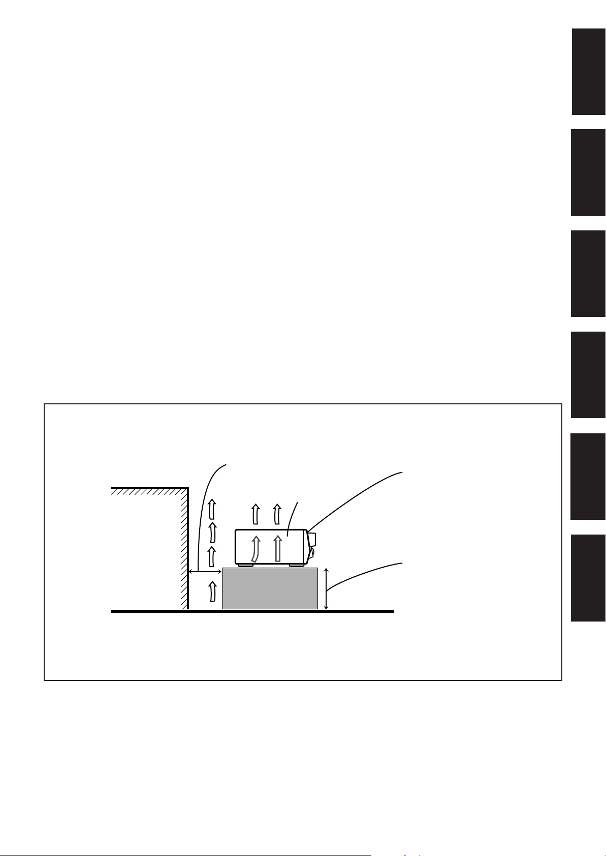
Caution: Proper Ventilation
To avoide risk of electric shock and fire and to protect from damage.
Locate the apparatus as follows:
Front: No obstructions open spacing.
Sides: No obstructions in 10 cm from the sides.
Top: No obstructions in 10 cm from the top.
Back: No obstructions in 15 cm from the back
Bottom: No obstructions, place on the level surface.
In addition, maintain the best possible air circulation as illustrated.
Achtung: Angemessene Ventilation
Stellen Sie das Gerät zur Verhütung von elektrischem Schlag und
Feuer und zum Schutz gegen Beschädigung wie folgt auf:
Vorderseite: Offener Platz ohne Hindernisse.
Seiten: Keine Hindernisse innerhalb 10 cm von den Seiten.
Oberseite: Keine Hindernisse innerhalb 10 cm von der Oberseite.
Rückseite: Keine Hindernisse innerhalb 15 cm von der Rückseite.
Unterseite: Keine Hindernisse. Auf eine ebene Oberfläche stellen.
Zusätzlich die bestmögliche Luftzirkulation wie gezeigt erhalten.
Attention: Ventilation Correcte
Pour éviter les chocs électriques, l’incendie et tout autre dégât.
Disposer l’appareil en tenant compte des impératifs suivants
Avant: Rien ne doit gêner le dégagement
Flancs: Laisser 10 cm de dégagement latéral
Dessus: Laisser 10 cm de dégagement supérieur
Arrière: Laisser 15 cm de dégagement arrière
Dessous: Rien ne doit obstruer par dessous; poser l’appareil sur
une surface plate.
Veiller également à ce que l’air circule le mieux possible comme
illustré.
Voorzichtig: Zorg Voor Goede Ventilatie
Om gevaar voor brand of een elektrische schok te voorkomen, dient u
bij opstelling van het apparaat op de volgende punten te letten:
Voorkant: Voldoende ruimte vrij houden.
Zijkanten: Minstens 10 cm aan weerszijden vrij houden.
Bovenkant: Niets bovenop plaatsen; 10 cm speling geven.
Achterkant: Minstens 15 cm ruimte achteraan vrij houden.
Onderkant: Opstellen op een egaal horizontaal oppervlak.
Bovendien moet er rondom voldoende luchtdoorstroming zijn, zoals in
de afbeelding aangegeven.
Precaución: Ventilación Adecuada
Para evitar el riesgo de choque eléctrico e incendio y para proteger el
aparato contra daños.
Ubique el aparato de la siguiente manera:
Frente: Espacio abierto sin obstrucciones
Lados: 10 cm sin obstrucciones a los lados
Parte superior: 10 cm sin obstrucciones en la parte superior
Parte trasera: 15 cm sin obstrucciones en la parte trasera
Fondo: Sin obstrucciones, colóquelo sobre una superficie
nivelada
Además, mantenga la mejor circulación de aire posible como se
ilustra.
Attenzione: Problemi di Ventilazione
Per evitare il rischio di folgorazioni ed incendi e proteggere l’unità da
danni, installarla nel modo seguente.
Davanti: Nessun ostacolo, spazio libero
Lati: Nessun ostacolo per almeno 10 cm
Sopra: Nessun ostacolo per almeno 10 cm
Retro: Nessun ostacolo per almeno 15 cm
Fondo: Libero ed in piano
Inoltre, mantenere il più possibile la circolazione dell’aria.
English
Deutsch
Français
Wall or obstructions
Wand oder Hindernisse
Mur, ou obstruction
Wand of meubilair
Pared u obstrucciones
Parete o ostacol
Spacing 15 cm or more
Abstand von 15 cm oder mehr
Dégagement de 15 cm ou plus
Minstens 15 cm tussenruimte
Espacio de 15 cm o más
15 cm di distanza o più
RX-668RBK
Floor
Boden
Plancher
Vloer
Piso
Pavimento
Front
Vorderseite
Avant
Voorkant
Frente
Davanti
Stand height 15 cm or more
Standhöhe 15 cm oder mehr
Hauteur du socle: 15 cm ou plus
Standard op minstens 15 cm van de vloer
Allura del soporte 15 cm o más
Altezza del tavolino 15 cm p plù
Nederlands
Español
Italiano
G-2

Table of Contents
Parts Identification ……………………………….. 2
English
Getting Started ……………………………………. 3
Before Installation ……………………………………………………………. 3
Checking the Supplied Accessories ……………………………………. 3
Connecting the FM and AM (MW/LW) Antennas ………………… 3
Connecting the Speakers …………………………………………………… 4
Connecting Audio/Video Components………………………………… 5
Connecting the Power Cord ………………………………………………. 7
Putting Batteries in the Remote Control ……………………………… 7
Basic Operations ………………………………….. 8
Turning the Power On and Off (Standby) ……………………………. 8
Selecting the Source to Play………………………………………………. 8
Adjusting the Volume……………………………………………………….. 9
Selecting the Front Speakers ……………………………………………… 9
Muting the Sound …………………………………………………………….. 9
Recording a Source ………………………………………………………….. 9
Attenuating the Input Signal ……………………………………………. 10
Adjusting the Front Speaker Output Balance……………………… 10
Reinforcing the Bass ………………………………………………………. 10
Adjusting the Tone …………………………………………………………. 10
Basic Settings ……………………………………. 11
Changing the Source Name……………………………………………… 11
Setting Center and Rear Speakers for the DSP Modes ………… 11
Using the Sleep Timer…………………………………………………….. 12
Storing the Basic Settings and Adjustments — One Touch
Operation ………………………………………………………………… 12
Receiving Radio Broadcasts …………………… 13
Tuning in Stations Manually ……………………………………………. 13
Using Preset T uning ……………………………………………………….. 13
Selecting the FM Reception Mode……………………………………. 14
Using the RDS to Receive FM Stations………………………………. 14
Searching for a Program by PTY Codes ……………………………. 15
Switching to a Broadcast Program of Your Choice
Temporarily ……………………………………………………………… 16
Using the DSP Modes ………………………….. 17
Available DSP Modes According to the Speaker Arrangement .. 18
Adjusting the 3D-PHONIC Modes …………………………………… 19
Adjusting the DAP Modes ………………………………………………. 19
Adjusting the Surround Modes — Dolby Surround and JVC
Theater Surround ……………………………………………………… 20
Activating the DSP Modes………………………………………………. 21
Using the DVD MULTI Playback Mode ………. 22
Activating the DVD MULTI Playback Mode …………………….. 22
Using the On-Screen Menus …………………… 23
Selecting the Source to Play……………………………………………..23
Using the DSP Modes …………………………………………………….. 23
Adjusting the Front Speaker Output Balance……………………… 23
Reinforcing the Bass ………………………………………………………. 24
Attenuating the Input Signal ……………………………………………. 24
Adjusting the DSP Modes ……………………………………………….. 24
Adjusting the DVD MULTI Playback Modes…………………….. 25
Adjusting the Tone …………………………………………………………. 25
Setting the Basic Setting Items ………………………………………… 25
Operating the Tuner………………………………………………………… 26
Storing the Preset Stations ………………………………………………. 26
Checking the RDS Information………………………………………… 26
COMPU LINK Remote Control System ……… 27
TEXT COMPU LINK Remote Control System .. 28
Showing the Disc Information on the TV Screen ……………….. 29
Searching a Disc (Only for the CD player) ………………………… 30
Entering the Disc Information………………………………………….. 31
Operating JVC’s Audio/Video Components … 33
Troubleshooting ………………………………….. 35
Specifications …………………………………….. 36
1
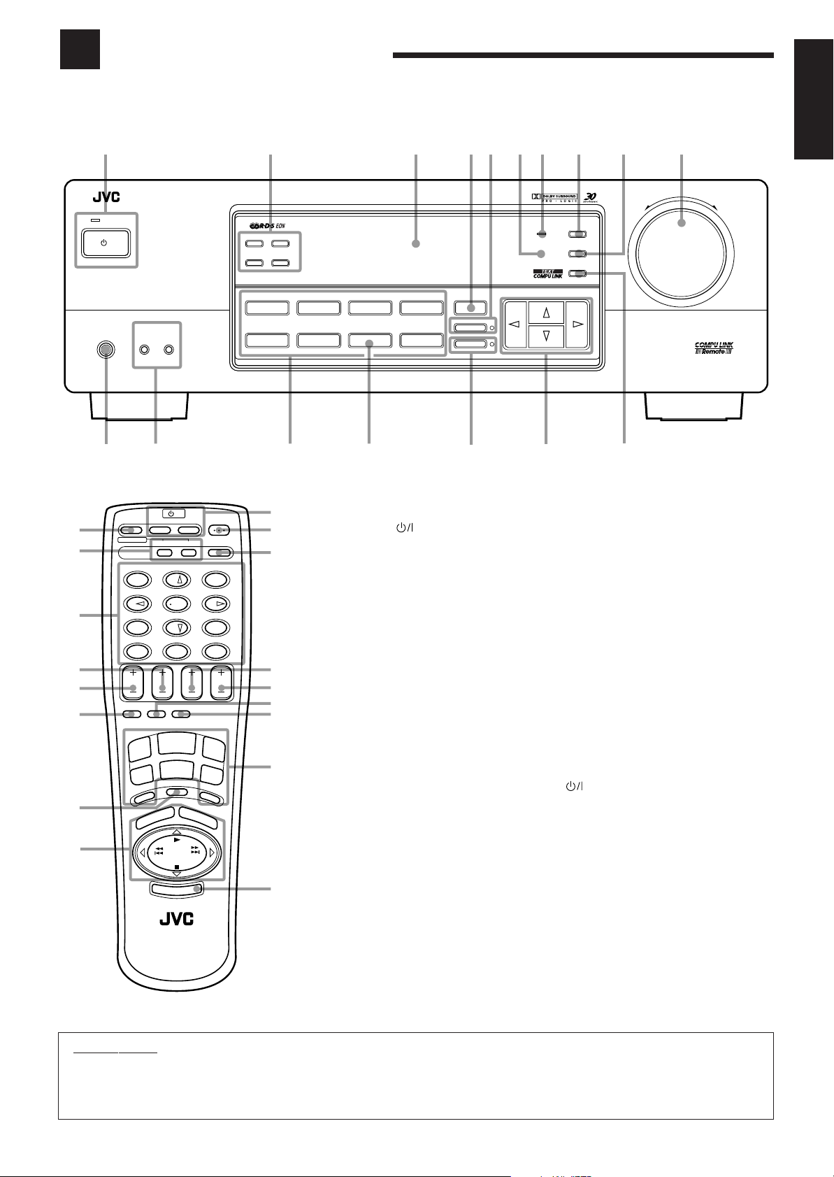
Parts Identification
Become familiar with the buttons and controls on the receiver before use.
Refer to the pages in parentheses for details.
English
123
RX-668R AUDIO/VIDEO CONTROL RECEIVER
STANDBY
PTY SEARCH
DISPLAY MODE
EON TA/NEWS/INFO
DVD MULTI
CD
9
p
q
w
e
r
t
y
u
DVD
PHONO
t
VCR
TAPE/MD
SOURCE NAME
r
TV SOUND
FM/AM
Front Panel
1 STANDBY/ON button and STANDBY
lamp (8)
2 RDS operation buttons (14)
PTY SEARCH, DISPLAY MODE, EON, TA/
NEWS/INFO
3 Display (8)
4 SURROUND button (19)
5 ONE TOUCH OPERATION button and lamp
(12)
6 Remote sensor (7)
7 BASS BOOST lamp (10)
8 ADJUST button (10) *
9 SETTING button (11) *
p MASTER VOLUME control (9)
q MEMORY button (13)
w Cursor control buttons
e INPUT ATT. button and lamp (10)
r SOURCE NAME button (11)
t Source selecting buttons (8)
DVD MULTI, DVD, VCR, TV SOUND, CD,
PHONO, TAPE/MD, FM/AM *
y SPEAKERS 1/2 buttons (9)
u PHONES jack (9)
1
2
3
4
5
6
7
8
/I
STANDBY/ON
PHONES
u
SPEAKERS
1
— OFF_ ON
y
SOUND
CONTROL
TV VCR AUDIO
ON SCREEN
SET
EFFECT – CENTER +
MENU
7/P
+10
VOLUME VCR CH TV VOL. TV CH
SLEEP
ONE TOUCH
OPERATION
FM/AM
TV
SOUND
O
N
O
H
P
U
A
P
C
E
R
PTY –
REMOTE CONTROL
2
/I
54
0
TV/VIDEO
CD
VCR
T
U
M
E
S
PTY SEARCH
T
E
X
T
D
RM-SR668RU
EXIT
– REAR•L +
– REAR•R +100+
I
N
G
8
D
I
S
P
+
PTY
Y
A
L
P
I
S
SURROUNDTESTDELAY
TAPE/MD
DVD
D
V
D
L
A
Y
CD-DISC
321
6
98
10
M
U
L
T
I
RETURN
ENTER
45
SURROUND
ONE TOUCH OPERATION
INPUT ATT.
e
6879p
MASTER VOLUME
–+
w
ADJUST
SETTING
MEMORY
ENHANCED COMPULINK CONTROL SYSTEM
q
BASS BOOST
Remote Control
1 SOUND CONTROL button (19, 33)
2 ON SCREEN operation buttons (23)
SET, EXIT
3 • 10 keys for selecting preset channel (13)
• 10 keys for adjusting sound (19 – 22)
• 10 keys for operating audio/video components
(33)
• On-screen operation buttons (%, fi, @, #)
(23, 29)
4 VCR CH +/– button (34)
5 VOLUME +/– button (9)
6 SLEEP button (12)
7 MUTING button (9)
8 • Operating buttons for audio/video components
(33)
• RDS operation buttons (14)
PTY SEARCH, PTY +/–, DISPLAY
9
p AUDIO button (8)
q CD-DISC button (33)
w TV VOL. +/– button (34)
e TV CH +/– button (34)
r ONE TOUCH OPERATION button (12)
t TV/VIDEO button (34)
y Source selecting buttons (8)
u TEXT DISPLAY button (29)
buttons (34)
TV, VCR
FM/AM, CD, TAPE/MD, TV SOUND, VCR,
DVD, PHONO, DVD MULTI
IMPORTANT:
To use the Cursor control buttons (w) on the front panel:
What these buttons actually do depends on which function you are trying to adjust. Before using these buttons, select the function by
pressing one of the buttons marked with *.
2
Getting Started
This section explains how to connect audio/video components and speakers to the receiver, and how to connect the
power supply.
English
Before Installation
General
• Be sure your hands are dry.
• Turn the power off to all components.
• Read the manuals supplied with the components you are going to
connect.
Locations
• Install the receiver in a location that is level and protected from
moisture.
• The temperature around the receiver must be between –5˚ and 35˚
C (23˚ and 95˚ F).
• Make sure there is good ventilation around the receiver. Poor
ventilation could cause overheating and damage the receiver.
Handling the receiver
• Do not insert any metal object into the receiver.
• Do not disassemble the receiver or remove screws, covers, or
cabinet.
• Do not expose the receiver to rain or moisture.
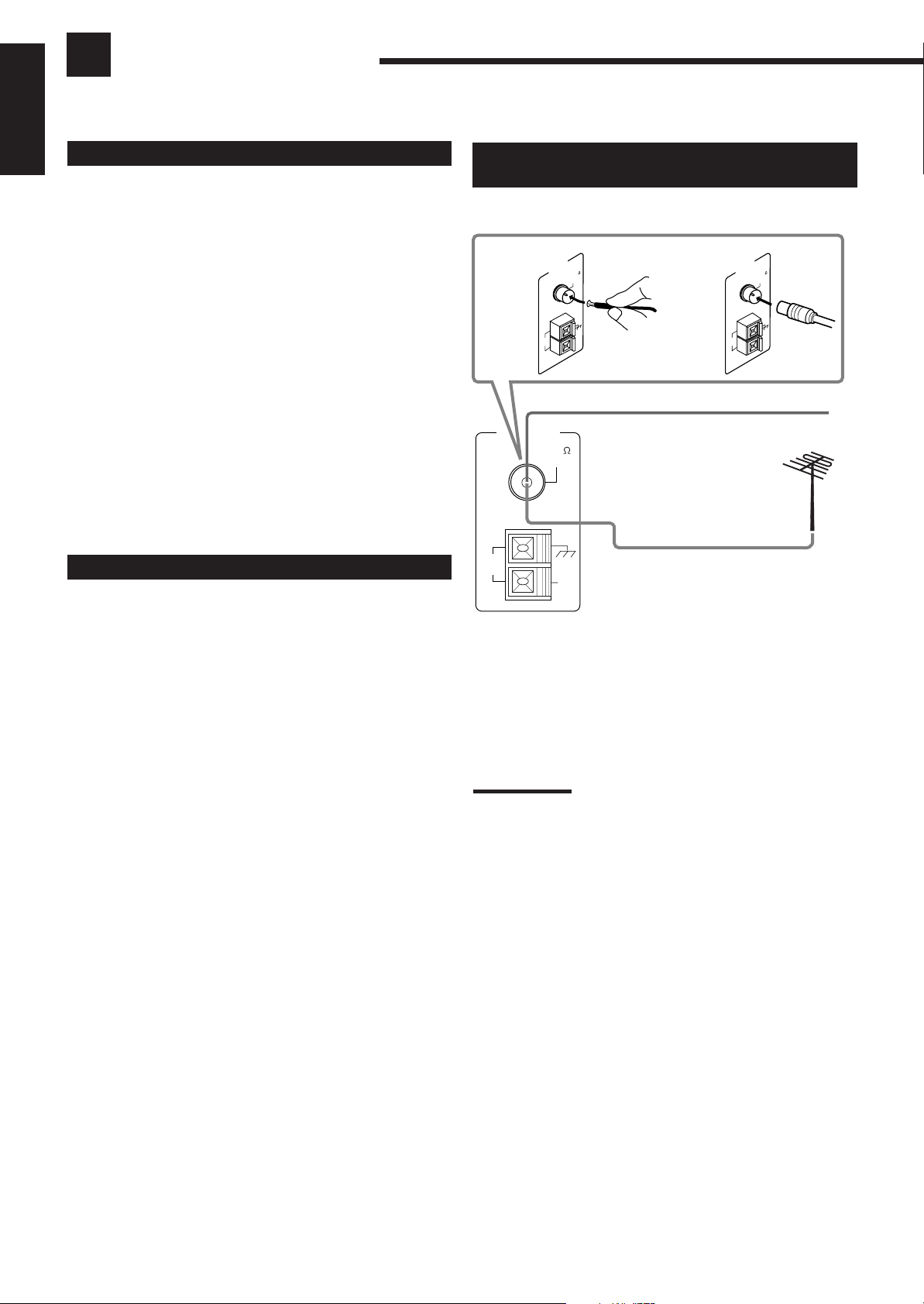
Connecting the FM and AM (MW/LW)
Antennas
FM Antenna Connections
A
ANTENNA
ANTENNA
AM
LOOP
FM 75
COAXIAL
ANTENNA
FM 75
C
L
IA
X
A
O
AM
EXT
B
AM
LOOP
FM Antenna
Extend the supplied FM antenna horizontally.
FM 75
O
C
L
IA
X
A
AM
EXT
Checking the Supplied Accessories
Check to be sure you have all of the following items, which are
supplied with the receiver.
The number in the parentheses indicates quantity of the pieces
supplied.
• Remote Control (1)
• Batteries (2)
• AM (MW/LW) Loop Antenna (1)
• FM Antenna (1)
If anything is missing, contact your dealer immediately.
AM
LOOP
AM
EXT
Outside FM Antenna Cable
A. Using the Supplied FM Antenna
The FM antenna provided can be connected to the FM 75Ω
COAXIAL terminal as temporary measure.
B. Using the Standard Type Connector (Not Supplied)
A standard type connector (IEC or DIN45325) should be
connected to the FM 75Ω COAXIAL terminal.
Note:
If reception is poor, connect the outside antenna.
Before attaching a 75
to an outside antenna), disconnect the supplied FM antenna.
Ω
coaxial cable (the kind with a round wire going
3
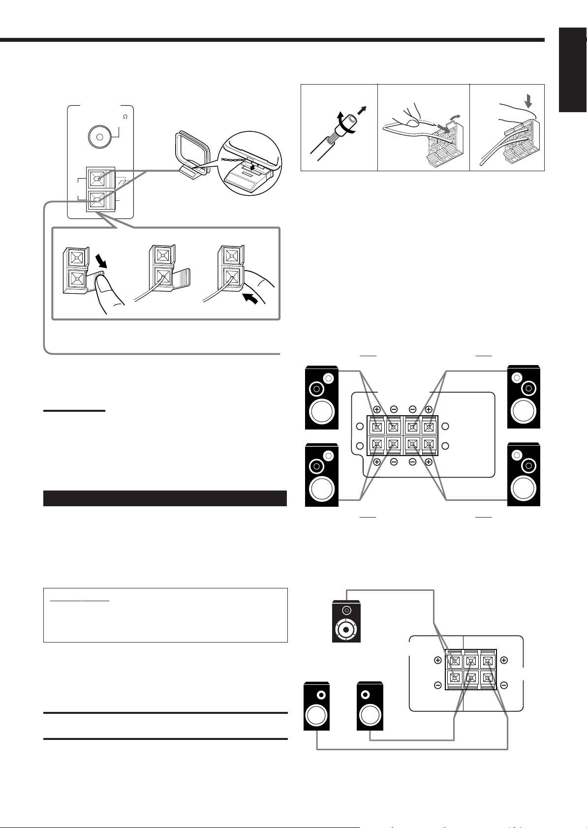
AM (MW/LW) Antenna Connections
RIGHT LEFT
FRONT SPEAKERS
1
2
1
2
ANTENNA
FM 75
COAXIAL
Snap the tabs on the loop into the
slots of the base to assemble the
AM (MW/LW) loop.
Basic connecting procedure
1
2
3
English
AM
LOOP
1
AM
EXT
AM (MW/LW) Loop Antenna
2
3
Outdoor single vinyl-covered wire
Turn the loop until you have the best reception.
Notes:
• Make sure the antenna conductors do not touch any other
terminals, connecting cords and power cord. This could cause poor
reception.
• If reception is poor, connect an outdoor single vinyl-covered wire to
the AM EXT terminal. (Keep the AM (MW/LW) loop antenna
connected.)
1 Cut, twist and remove the insulation at the end of
each speaker signal cable.
2 Open the terminal and then insert the speaker
signal cable.
3 Close the terminal.
Connecting the front speakers
You can connect two pairs of front speakers (one pair to the FRONT
SPEAKERS 1 terminals, and another pair to the FRONT
SPEAKERS 2 terminals).
Right speaker
FRONT SPEAKERS 1
Left speaker
Connecting the Speakers
You can connect the following speakers:
• Two pairs of front speakers to produce normal stereo sound.
• One pair of rear speakers to enjoy the surround effect.
• One center speaker to produce more effective surround effect (to
emphasize human voices).
• One subwoofer to enhance the bass.
IMPORTANT:
After connecting the speakers listed above, set the speaker
setting information properly to obtain the best possible
surround effect. For details, see page 11.
For each speaker (except for a subwoofer), connect the (–) and (+)
terminals on the rear panel to the (–) and (+) terminals marked on
the speakers. For connecting a subwoofer, see page 5.
CAUTION:
Use speakers with the SPEAKER IMPEDANCE indicated by the
speaker terminals.
Right speaker
FRONT SPEAKERS 2
Left speaker
Connecting the rear and center speakers
Connect rear speakers to the REAR SPEAKERS terminals and a
center speaker to the CENTER SPEAKER terminals.
Center speaker
Left rear
speaker
Right rear
speaker
CENTER
SPEAKER
RIGHT LEFT
SPEAKERS
REAR
4
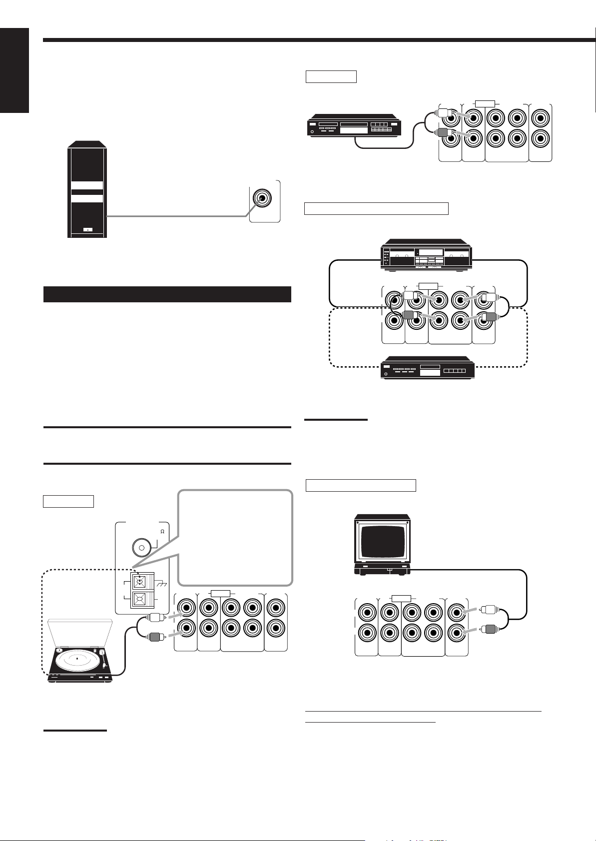
Connecting the subwoofer speaker
English
You can enhance the bass by connecting a subwoofer.
Connect the input jack of a powered subwoofer to the
SUBWOOFER OUT jack on the rear panel, using a cable with RCA
pin plugs.
SUBWOOFER
OUT
CD player
CD player
To audio output
Cassette deck or MD recorder
Cassette deck
PHONO
L
R
AUDIO
OUT
(REC)IN(PLAY)
TAPE/MDCD
TV
SOUND
Powered subwoofer
Connecting Audio/Video Components
You can connect the following audio/video components to this
receiver using cables with RCA pin plugs (not supplied). Refer also
to the manuals supplied with your components.
Audio component connections
Use the cables with RCA pin plugs (not supplied).
Connect the white plug to the audio left jack, and the red plug to the
audio right jack.
CAUTION:
If you connect a sound-enhancing device such as a graphic equalizer
between the source components and this receiver, the sound output
through this receiver may be distorted.
Turntable
AM
LOOP
ANTENNA
FM 75
COAXIAL
If an earth cable is
provided for your
turntable, connect the
cable to the ground
terminal (H) of the
ANTENNA terminals on
the rear panel.
AM
EXT
PHONO
L
R
AUDIO
TAPE/MDCD
OUT
(REC)IN(PLAY)
TV
SOUND
To audio input
To audio input
PHONO
L
R
AUDIO
OUT
(REC)IN(PLAY)
TAPE/MDCD
To audio output
TV
SOUND
To audio output
MD recorder
Note:
You can connect either a cassette deck or an MD recorder to the
TAPE/MD jacks. When connecting an MD recorder to the TAPE/MD
jacks, change the source name, which will be shown on the display
when selected as the source, to “MD.” See page 11 for details.
TV (as the sound source)
TV
To audio output
PHONO
L
R
AUDIO
OUT
(REC)IN(PLAY)
TAPE/MDCD
TV
SOUND
To audio output
Turntable
Note:
Any turntables incorporating a small-output cartridge such as an MC
(moving-coil type) must be connected to this receiver through a
commercial head amplifier or step-up transformer. Direct connection
may result in insufficient volume.
5
If your audio components have a COMPU LINK-3 or
TEXT COMPU LINK terminal
• See also page 27 for detailed information about the connection and
the COMPU LINK-3 remote control system.
• See also page 28 for detailed information about the connection and
the TEXT COMPU LINK remote control system.
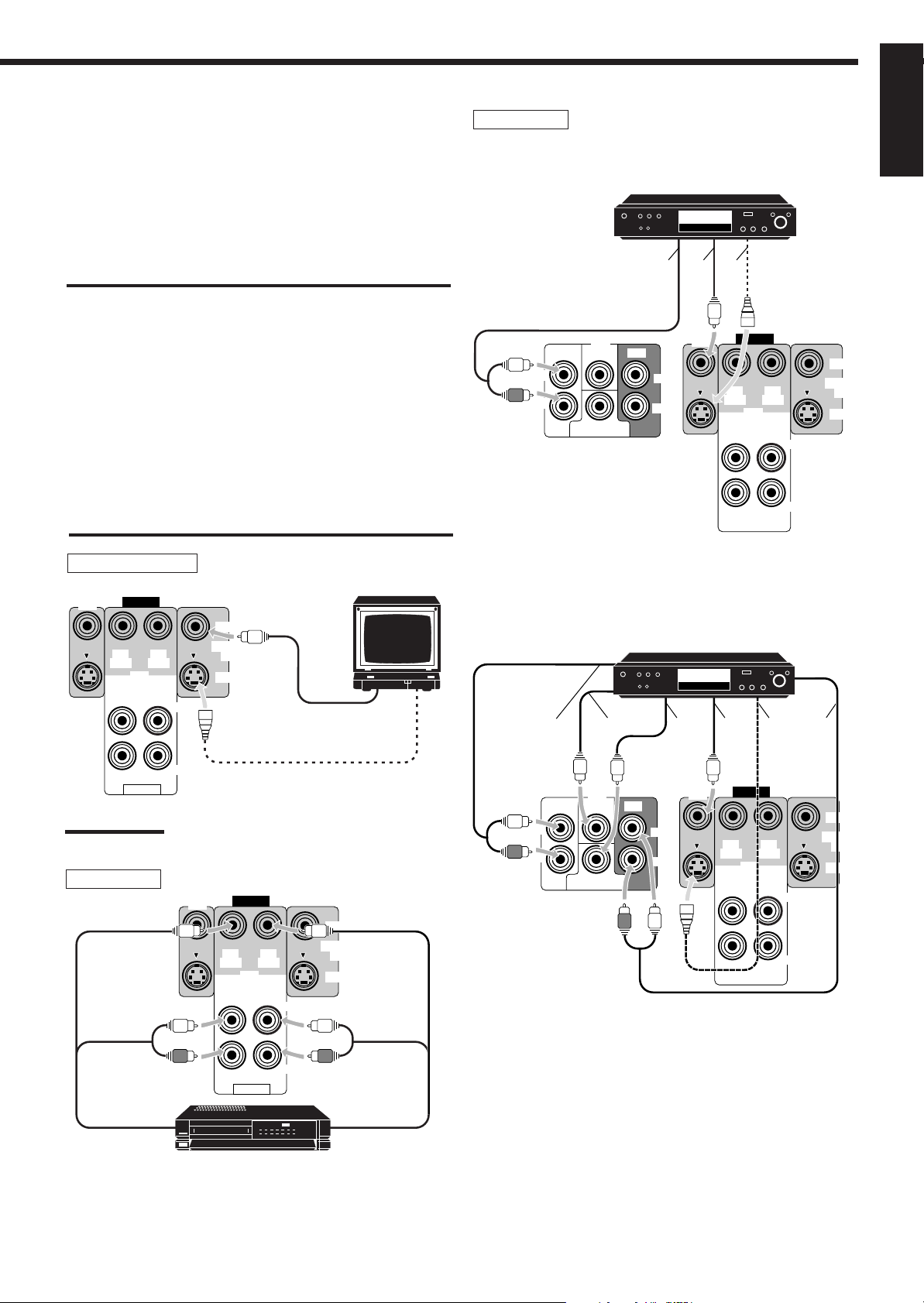
Video component connections
Use the cables with RCA pin plugs (not supplied).
Connect the white plug to the audio left jack, the red plug to the
audio right jack, and the yellow plug to the video jack.
If DVD player and TV have S-video (Y/C-separation) terminals,
connect them using S-video cables (not supplied). Connecting these
video components through the S-video input/output terminals will
give you better picture playback quality.
DVD player
• When you connect the DVD player with stereo output jacks:
DVD player
DVD
English
IMPORT ANT:
This receiver is equipped with both the composite video and S-video
input terminals for the DVD player connection.
You do not have to connect both the composite video and S-video
terminals.
However, remember that the video signals from the composite
video input terminal are output only through the composite
video output terminals, while the ones from the S-video input
terminal are output only through the S-video output terminal.
Therefore, if your DVD player is connected to the receiver only
through the S-video input terminal, you cannot record the picture
from the DVD player on the VCR.
In addition, if the TV and the DVD player are connected to the
receiver through the different video terminals, you cannot view the
playback picture from the DVD player on the TV.
TV (as the monitor)
TV (or Monitor)
DVD
VIDEO
OUT
(REC)IN(PLAY)
VCR
OUT
(REC)IN(PLAY)
LEFT
VIDEO
MONITOR
OUT
S-VIDEO
To composite video input
Å ı Ç
DVD
VIDEO
OUT
(REC)IN(PLAY)
VCR
OUT
(REC)IN(PLAY)
LEFT
RIGHT
VIDEO
MONITOR
OUT
S-VIDEO
DVD
FRONT CENTER REAR
L
R
SUBWOOFER
DVD
LEFT
RIGHT
Å To front left/right channel audio
output (or to audio mixed output if
necessary)
ı To composite video output
Ç To S-video output (for better
playback picture quality)
• When you connect the DVD player with its analog discrete output
(5.1 CH reproduction) jacks:
DVD player
Å
ı Ç ‰Î Ï
RIGHT
AUDIO
Note:
To S-video input
(when the DVD player is connected
using the S-video terminal)
Use the video components of the PAL- or multi- color system.
VCR
DVD
To audio/video
input
VIDEO
OUT
(REC)IN(PLAY)
VCR
OUT
(REC)IN(PLAY)
AUDIO
VHS
VCR
LEFT
RIGHT
VIDEO
MONITOR
OUT
S-VIDEO
To audio/video
output
DVD
FRONT CENTER REAR
L
R
SUBWOOFER
DVD
LEFT
RIGHT
VIDEO
OUT
(REC)IN(PLAY)
VCR
OUT
(REC)IN(PLAY)
LEFT
RIGHT
Å To front left/right channel audio output
ı To center channel audio output
Ç To subwoofer audio output
Î To composite video output
‰ To S-video output (for better playback picture quality)
Ï To rear left/right channel audio output
VIDEO
MONITOR
OUT
S-VIDEO
6
English
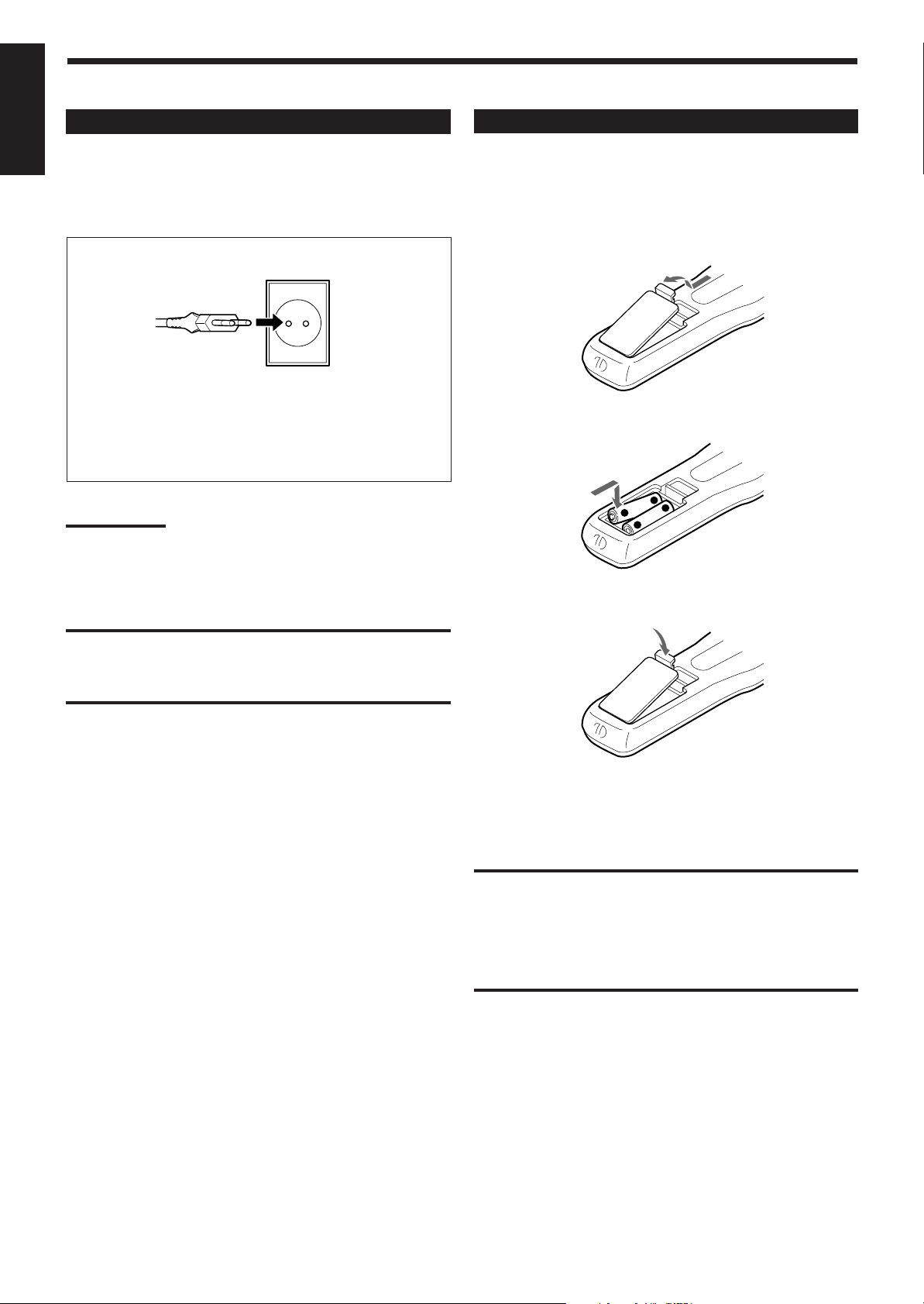
Connecting the Power Cord
Before plugging the receiver into an AC outlet, make sure that all
connections have been made.
Plug the power cord into an AC outlet.
Putting Batteries in the Remote Control
Before using the remote control, put two supplied batteries first.
When using the remote control, aim the remote control directly at
the remote sensor on the receiver.
1. On the back of the remote control, remove the
battery cover as illustrated.
Keep the power cord away from the connecting cables and the
antenna. The power cord may cause noise or screen interference.
We recommend that you use a coaxial cable to connect the
antenna, since it is well-shielded against interference.
Note:
The preset settings such as preset channel and sound adjustment
may be erased in a few days in the following cases:
– When you unplug the power cord.
– When a power failure occurs.
CAUTIONS:
• Do not touch the power cord with wet hands.
• Do not pull on the power cord to unplug the cord. When
unplugging the cord, always grasp the plug so as not to damage
the cord.
2. Insert batteries. Make sure to observe the proper
polarity: (+) to (+) and (–) to (–).
+
+
—
R6P (SUM-3)/AA (15F)
3. Replace the cover.
If the range or effectiveness of the remote control decreases, replace
the batteries. Use two R6P (SUM-3)/AA (15F) type dry-cell
batteries.
7
CAUTION:
Follow these precautions to avoid leaking or cracking cells:
• Place batteries in the remote control so they match the polarity
indicated: (+) to (+) and (–) to (–).
• Use the correct type of batteries. Batteries that look similar may
differ in voltage.
• Always replace both batteries at the same time.
• Do not expose batteries to heat or flame.
Basic Operations
The following operations are commonly used when you play any sound source.
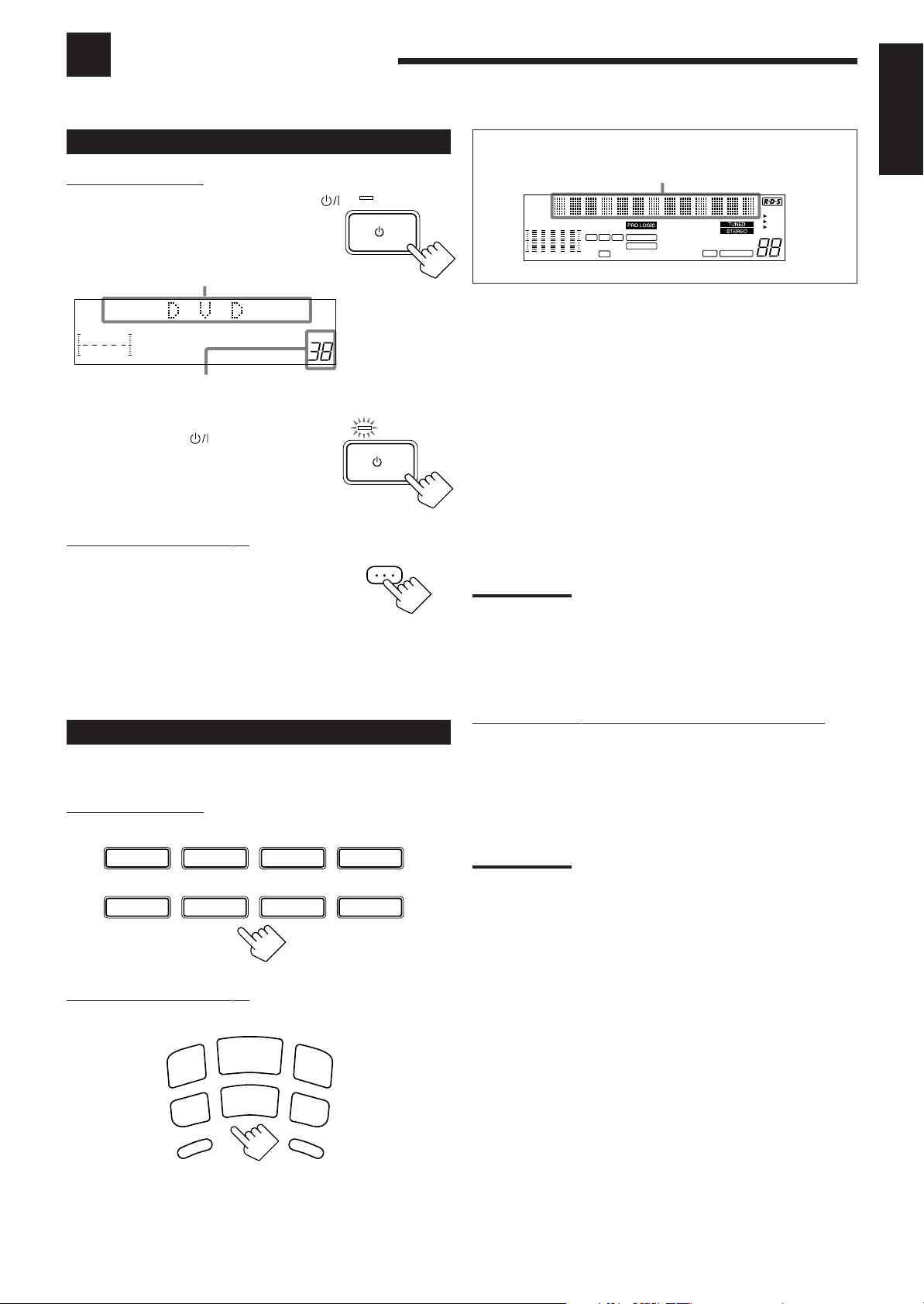
Turning the Power On and Off (Standby)
On the front panel:
To turn on the power, press STANDBY/ON .
The STANDBY lamp goes off. The name of the
current source (or station frequency) appears on
the display.
Current source name appears
VOLUME
100 1k 10k
Current volume level is shown here
To turn off the power (into standby mode),
press STANDBY/ON
again.
The STANDBY lamp lights up. A small amount
of power is consumed in standby mode. To turn
the power off completely, unplug the AC power
cord.
From the remote control:
To turn on the power, press AUDIO.
The STANDBY lamp goes off. The name of the
current source (or station frequency) appears on
the display.
To turn off the power (into standby mode),
press AUDIO again.
The STANDBY lamp lights up.
STANDBY
/I
STANDBY/ON
STANDBY
/I
STANDBY/ON
AUDIO
Selected source name appears
MUTE AUTO
SLEEPAT T
EON
TA
NEWS
INFO
VOLUME
CH–
100 1k 10k
LSC
R
D S P
3D-PHONC
THEATER
LIVE CLUB ACTION
DANCE CLUB
HALL
PA VILION
DVD MULTI Select the DVD player for viewing the digital video
disc using the analog discrete output mode (5.1CH
reproduction) on the DVD player.
To enjoy the DVD MULTI playback, see page 22.
DVD Select the DVD player for viewing the stereo digital
video disc.
VCR Select the video component connected to the VCR
jacks.
TV SOUND Select the TV sound.
CD * Select the CD player.
PHONO * Select the turntable.
TAPE/MD * Select the cassette deck (or the MD recorder).
FM/AM * Select an FM or AM (MW/LW) broadcast.
Each time you press the button, the band alternates
between FM and AM (MW/LW).
Notes:
• When connecting an MD recorder (to the TAPE/MD jacks), change
the source name that appears on the display. See page 11 for
details.
• When you press one of the source selecting buttons on the remote
control marked above with an asterisk (*), the receiver
automatically turns on.
English
Selecting the Source to Play
Press one of the source selecting buttons.
On the front panel:
DVD MULTI
CD
From the remote control:
DVD
PHONO
M
/A
M
F
V
T
U
O
S
O
H
P
VCR
D
N
O
N
CD
VCR
TAPE/MD
SOURCE NAME
TA
D
V
P
E
/M
D
V
D
D
M
U
L
T
Selecting different sources for picture and sound
You can watch picture from a video component while listening to
sound from another component.
Press one of the audio source selecting buttons (CD, TAPE/MD,
PHONO, FM/AM, TV SOUND), while viewing the picture from a
video component such as the VCR or DVD player, etc.
TV SOUND
Note:
FM/AM
D
I
Once you have selected a video source, pictures of the selected
source are sent to the TV until you select another video source.
8
English
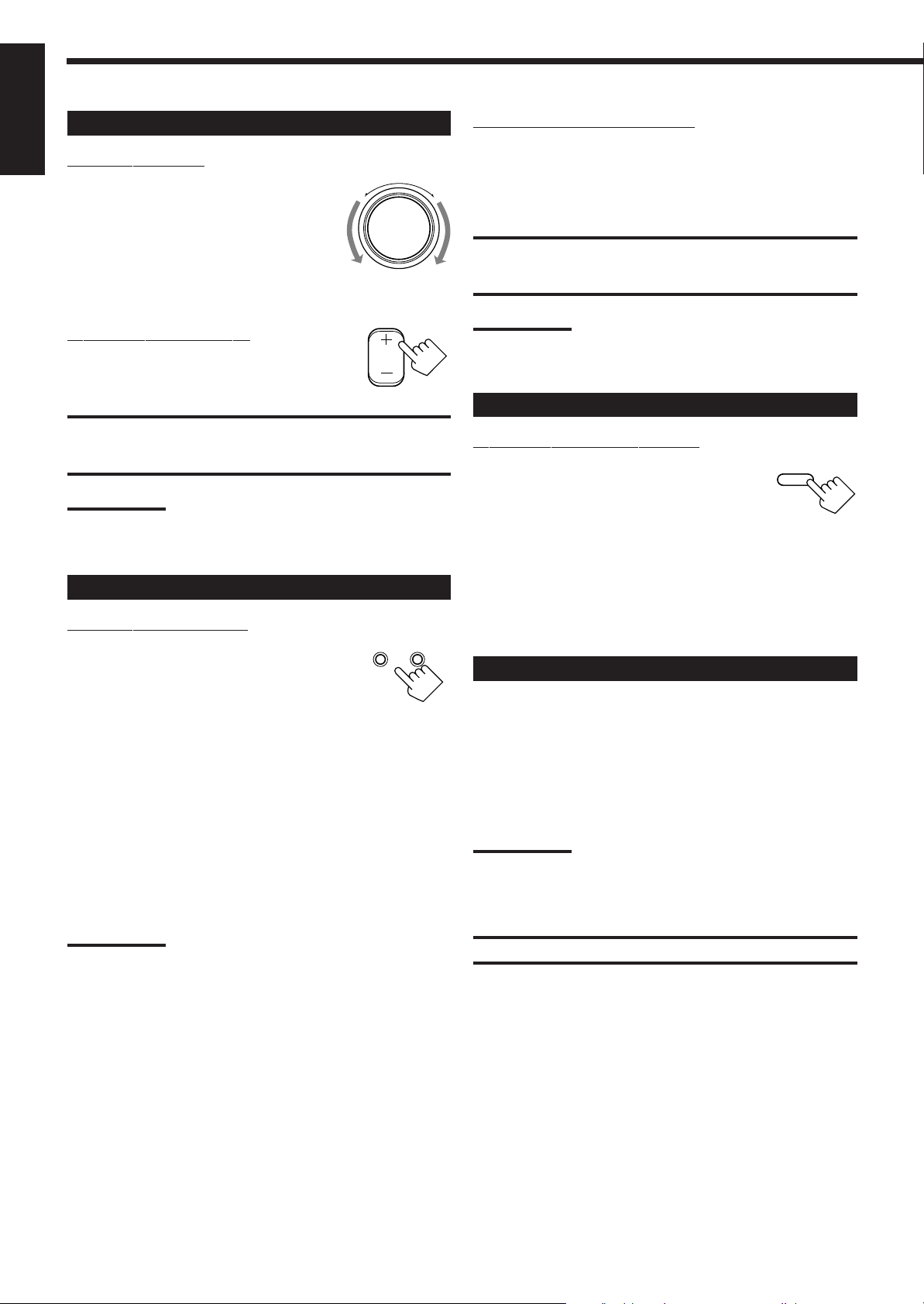
Adjusting the Volume
On the front panel:
To increase the volume, turn MASTER
VOLUME clockwise.
To decrease the volume, turn it
counterclockwise.
• When you turn MASTER VOLUME rapidly,
the volume level also changes rapidly.
• When you turn MASTER VOLUME slowly,
the volume lev el also changes slowly.
From the remote control:
To increase the volume, press VOLUME +.
To decrease the volume, press VOLUME –.
–
VOLUME
MASTER VOLUME
Listening only with headphones
1. Connect a pair of headphones to the PHONES jack on the front
panel.
2. Press SPEAKERS 1 and SPEAKERS 2 to set them in the —
+
OFF position.
CAUTION:
Be sure to turn down the volume before connecting or putting on
headphones, as high volume can damage both the headphones and
your hearing.
Note:
You cannot shut off the sound through the other speakers using the
SPEAKERS 1 and 2 buttons.
CAUTION:
Always set the volume to the minimum before starting any source. If
the volume is set at its high level, the sudden blast of sound energy
can permanently damage your hearing and/or ruin your speakers.
Note:
The volume level can be adjusted within the range of “0” (minimum)
to “80” (maximum).
Selecting the Front Speakers
On the front panel ONLY:
When you have connected two pairs of the front
speakers, you can select which to use. Pressing
SPEAKERS 1 or SPEAKERS 2 activates the
respective set of speakers.
• To use the speakers connected to the FRONT SPEAKERS 1
terminals, press SPEAKERS 1 to set it in the _ ON position, and
press SPEAKERS 2 to set it in the — OFF position.
• To use the speakers connected to the FRONT SPEAKERS 2
terminals, press SPEAKERS 2 to set it in the _ ON position, and
press SPEAKERS 1 to set it in the — OFF position.
• To use both sets of the speakers, press SPEAKERS 1 to set it in
the _ ON position, and press SPEAKERS 2 to set it in the _ ON
position.
• To use neither set of the speakers, press SPEAKERS 1 and
SPEAKERS 2 to set them in the — OFF position.
SPEAKERS
12
_ ON — OFF
Muting the Sound
From the remote control ONLY:
Press MUTING to mute the sound through all
T
I
N
U
G
M
speakers and headphones connected.
“MUTING” appears on the display and the
volume turns off (the volume level indicator goes
off).
To restore the sound, press MUTING again so that “OFF” appears
on the display.
• Turning MASTER VOLUME or pressing VOLUME +/– also
restores the sound.
Recording a Source
You can record any source playing through the receiver to a cassette
deck (or an MD recorder) connected to the TAPE/MD jacks and the
VCR connected to the VCR jacks at the same time.
While recording, you can listen to the selected sound source at
whatever sound level you like, without affecting the sound levels of
the recording.
Note:
The output volume level, tone adjustment (see page 10), Bass Boost
(see page 10) and DSP modes (see page 19) cannot affect the
recording.
Note:
When only one set of the speakers is connected to either the FRONT
SPEAKERS 1 or 2 terminals, do not activate both pairs of the
speakers. If you do, no sound comes out of the front speakers.
9
IMPORTANT:
Before recording, turn off the DVD MULTI playback mode.
Loading…
-
Page 1: JVC HR-J668EU
VIDEO CASSETTE RECORDER INSTRUCTIONS LPT0198-001A PAL H R-J711EU H R-J668EU STANDBY/ON TIMER REC LINK TV PROG DISPLAY T V P R O G + T V P R O G – T V – T V + TV 0000 START DEBUT STOP FIN DATE MENU OK TV PROG TV/VCR DAILY/QTDN. VPS/PDC AUX ? WEEKLY/HEBDO PROG 30 SEC – –:– – AUDIO 123 456 7 89 0 2 4 1 3 EXPRESS FIRST SEE AUTO SET-UP ON BA[…]
-
Page 2: JVC HR-J668EU
2 EN SAFETY FIRST Failure to heed the following precautions may result in damage to the recorder , remote control or video cassette. 1. DO NOT place the recorder . . . … in an environment prone to extreme temperatures or humidity . … in direct sunlight. … in a dusty environment. … in an environment where strong magnetic fields are generated[…]
-
Page 3: JVC HR-J668EU
EN 3 Basic Connections CHECK CONTENTS 1 Make sure the package contains all of the accessories listed in “Specifications” ( Z pg. 53). SITUA TE RECORDER 2 Place the recorder on a stable, horizontal surface. CONNECT RECORDER TO TV 3 The connection method you use depends on the type of TV you have. RF CONNECTION ● T o Connect T o A TV W ith NO A[…]
-
Page 4: JVC HR-J668EU
4 EN INITIAL SETTINGS When the button on the recorder/remote control is pressed for the first time to power on the recorder after you plug the mains power cord into a mains outlet, the Country Set display will appear on the TV screen and the recorder’s front display panel. By simply selecting your country*, the Auto Set Up function sets the tu[…]
-
Page 5: JVC HR-J668EU
EN 5 CONFIRM/SET VIDEO CHANNEL 5 If you have connected the video recorder to your TV via an RF cable only (RF connection) The channel that is shown on the display panel is your V ideo Channel. T o view picture signals from the video recorder , set your TV to the V ideo Channel. — Refer to the instructions supplied with your TV set for how to do t[…]
-
Page 6: JVC HR-J668EU
6 EN INITIAL SETTINGS (cont.) Preset Download 123 456 7 89 0 2 4 1 3 ? OK When you connect the recorder and your TV via fully-wired 21-pin SCAR T cable ( Z pg. 3), you can set the recorder’s tuner channels by downloading preset data from your TV instead of using the Auto Set Up function ( Z pg. 4). After downloading is completed, the recorder […]
-
Page 7: JVC HR-J668EU
EN 7 If both auto channel set and auto clock set have been performed successfully: 1 T urn on the TV and select its VIDEO channel or A V mode, then make sure that all necessary stations have been stored in the recorder’s memory by using the TV PROG button(s). ● If station names (ID — Z pg. 41) have also been stored in the recorder’s m[…]
-
Page 8: JVC HR-J668EU
8 EN INITIAL SETTINGS (cont.) 123 456 7 89 0 2 4 1 3 ? Language This recorder offers you the choice to view on-screen messages in 13 different languages. Though Auto Set Up selects the language automatically ( Z pg. 7), you can change the language setting manually using this procedure as required. TURN ON THE RECORDER 1 Press . ACCESS MAIN MENU 2 P[…]
-
Page 9: JVC HR-J668EU
EN 9 On-Screen Displays Y ou can choose whether or not to have various operational indicators appear on screen, by setting this function ON or OFF . Messages appear in the selected language ( Z pg. 7 or 8). T urn on the TV and select the VIDEO channel (or A V mode). TURN ON THE RECORDER 1 Press . ACCESS MAIN MENU SCREEN 2 Press MENU . ACCESS MODE S[…]
-
Page 10: JVC HR-J668EU
10 EN Power Save Mode T urn on the TV and select the VIDEO channel (or A V mode). Y ou can reduce the power consumption while the recorder is turned off. TURN ON THE RECORDER 1 Press . ACCESS MAIN MENU SCREEN 2 Press MENU . ACCESS MODE SET SCREEN 3 Press %fi to move the highlight bar (pointer) to «MODE SET», then press OK or # . SELECT P[…]
-
Page 11: JVC HR-J668EU
EN 11 T -V LINK T -V Link Functions NexTV iew Link Y ou can download the EPG (Electronic Programme Guide) information from your TV for timer -programming on the recorder . For details, refer to the instruction manual for your TV . TV Auto Power On Y ou can turn on the TV and set it to video mode automatically whenever you play a tape. For details, […]
-
Page 12: JVC HR-J668EU
12 EN Colour System Set INFORMA TION ON COLOUR SYSTEM TURN ON THE RECORDER 1 Press . ACCESS MAIN MENU SCREEN 2 Press MENU . ACCESS MODE SET SCREEN 3 Press %fi to move the highlight bar (pointer) to «MODE SET», then press OK or # . SELECT COLOUR SYSTEM MODE 4 Press %fi to move the highlight bar (pointer) to «COLOUR SYSTEM», the[…]
-
Page 13: JVC HR-J668EU
EN 13 PLA YBACK Basic Playback The easiest, most basic operation possible with your video recorder is tape playback. Already-recorded signals on a video tape are read by your video recorder and displayed on your TV just like a TV programme. Usable cassettes LOAD A CASSETTE 1 Make sure the window side is up, the rear label side is facing you and the[…]
-
Page 14: JVC HR-J668EU
14 EN V ariable-Speed Search ACTIV A TE V ARIABLE-SPEED SEARCH 1 During playback, press @ or # ( ™ or £ ). ● The more times you press, the faster the playback picture moves. ● T o decrease speed, press the button for the opposite direction. T o resume normal playback, press PLA Y . PLA YBACK (cont.) Slow Motion ACTIV A TE SLOW-MOTION PLA YBA[…]
-
Page 15: JVC HR-J668EU
EN 15 Manual T racking Y our video recorder is equipped with automatic tracking control. During playback, you can override this and adjust the tracking manually by pressing the TV PROG buttons. OVERRIDE AUTOMA TIC TRACKING 1 Press on the remote to engage manual tracking. ADJUST TRACKING MANUALL Y 2 Press TV PROG + or – to adjust tracking. RETURN […]
-
Page 16: JVC HR-J668EU
16 EN Repeat Playback Y our video recorder can automatically play back the whole tape 50 times repeatedly . ST ART PLA YBACK 1 Press PLA Y . ACTIV A TE REPEA T PLA YBACK 2 Press PLA Y and hold for over 5 seconds, then release. ● The Play indicator ( ) on the display panel blinks slowly . ● The tape plays 50 times automatically , and then stops.[…]
-
Page 17: JVC HR-J668EU
EN 17 TV signals being received by the recorder ’ s built-in tuner can be recorded onto a video tape. Y ou can “capture” a TV programme using your video recorder . RECORDING Basic Recording 123 456 7 89 0 2 4 1 3 ? PAUSE STOP PLAY T urn on the TV and select the VIDEO channel (or A V mode). LOAD A CASSETTE 1 Insert a cassette with the record s[…]
-
Page 18: JVC HR-J668EU
18 EN RECORDING (cont.) Recording Features Record One Pr ogramme While W atching Another If your recorder is connected to the TV via A V connection, . . . . . . press TV/VCR . The recorder’s VCR indicator and the TV broadcast being recorded disappear . SELECT CHANNEL TO W A TCH 1 Once recording is in progress, all you need to do is to set the […]
-
Page 19: JVC HR-J668EU
EN 19 Receiving Stereo And Bilingual Pr ogrammes Y our recorder is equipped with a Sound-Multiplex decoder (A2) and a Digital stereo sound decoder (NICAM) making reception of stereo and bilingual broadcasts possible. When the channel is changed, the type of broadcast being received will be displayed on the TV screen for a few seconds. T o Record St[…]
-
Page 20: JVC HR-J668EU
20 EN 123 456 7 89 0 2 4 1 3 ? B.E.S.T . Picture System The B.E.S.T . (Biconditional Equalised Signal T racking) system checks the condition of the tape in use during recording and playback, and compensates to provide the highest-possible recording and playback pictures. The default setting for both recording and playback is “ON”. Preparation R[…]
-
Page 21: JVC HR-J668EU
EN 21 Recording ST ART RECORDING 1 Press and hold RECORD and press PLA Y on the remote, or press RECORD on the recorder . DURING B.E.S.T . B.E.S.T . COMPLETE ● The recorder spends approximately 7 seconds assessing the condition of the tape, then begins recording. NOTES: ● The B.E.S.T . system works for both SP and LP modes only after a tape has[…]
-
Page 22: JVC HR-J668EU
22 EN ACCESS SHOWVIEW SCREEN 1 Press PROG . The front display panel looks like this: ENTER SHOWVIEW NUMBER 2 Press the NUMBER keys to enter the S HOW V IEW number of a programme you wish to record. ● If you make a mistake, press and input the correct number . The S HOW V IEW number you enter appears on the front display panel: The display panel c[…]
-
Page 23: JVC HR-J668EU
EN 23 123 456 7 89 0 2 4 1 3 ? SET T APE SPEED 4 Press SP/LP ( ) to set the tape speed. SET VPS/PDC MODE 5 Press VPS/PDC to select «ON» or «OFF». If «VPS/PDC ON» is displayed on the screen or «VPS/ PDC» is lit on the display panel, VPS/PDC is set to ON. If «VPS/PDC OFF» is displayed on the screen or[…]
-
Page 24: JVC HR-J668EU
24 EN Express Timer Pr ogramming TIMER RECORDING (cont.) If you don’t know the S HOW V IEW number for the programme you wish to record, use the following procedure to set your recorder to timer -record the programme. ACCESS SHOWVIEW SCREEN 1 Press PROG . ACCESS PROGRAMME SCREEN 2 Press ST ART +/– . (If you’re just starting out, “P1” appea[…]
-
Page 25: JVC HR-J668EU
EN 25 ENTER CHANNEL POSITION 6 Press TV PROG +/– . SET T APE SPEED 7 Press SP/LP ( ) to set the tape speed. SET VPS/PDC MODE 8 Press VPS/PDC to select «ON» or «OFF». If «VPS/PDC ON» is displayed on the screen or «VPS/ PDC» is lit on the display panel, VPS/PDC is set to ON. If «VPS/PDC OFF» is disp[…]
-
Page 26: JVC HR-J668EU
26 EN Check, Cancel And Replace Pr ogrammes DISENGAGE TIMER MODE 1 Press ‰ ( TIMER ), then press . ACCESS PROGRAM CHECK SCREEN/DISPLA Y 2 Press . ACCESS PROGRAM SCREEN/ DISPLA Y 3 Press again to check more information. Each time you press , the next programme’s information appears. ● The display panel shows the programme start time. Pressi[…]
-
Page 27: JVC HR-J668EU
EN 27 Auto Timer When the Auto T imer is set to ON the timer is automatically engaged when the recorder power is turned off and automati- cally disengaged when the recorder is powered back on. ACCESS MAIN MENU SCREEN 1 Press MENU . ACCESS MODE SET SCREEN 2 Press %fi to move the highlight bar (pointer) to «MODE SET», then press OK or # . […]
-
Page 28: JVC HR-J668EU
28 EN This facility allows you record automatically a satellite programme which is timer -programmed on your external satellite tuner . Connect a satellite tuner to the recorder’s A V2 IN/DECODER connector ( Z pg. 32) and programme the timer on the satellite tuner; the recorder starts recording when the signals input from the satellite tuner t[…]
-
Page 29: JVC HR-J668EU
EN 29 ENTREE ANT. IN ENTREE/DECODEUR IN/DECODER AV2 ENTREE/SORTIE IN/OUT SORTIE RF OUT ANTENNE AV1 SORTIE OUT R L AUDIO 123 456 7 89 0 2 4 1 3 ? Edit Fr om A Camcorder EDITING NUMBER «0» TV PROG Y ou can use a camcorder as the source player and your video recorder as the recorder . MAKE CONNECTIONS 1 Connect the camcorder ’ s AUDIO/VIDE[…]
-
Page 30: JVC HR-J668EU
30 EN Edit T o Or Fr om Another V ideo Recorder Y ou can use your video recorder as the sour ce player or the recording deck. MAKE CONNECTIONS 1 Connect the player ’ s 21-pin SCAR T (A V) connector to the recorder’s 21-pin SCAR T (A V) connector as illustrated on page 31. When Using Y our V ideo Recorder As The Source Player . . . . . . connect[…]
-
Page 31: JVC HR-J668EU
EN 31 ENTREE ANT. IN ENTREE/DECODEUR IN/DECODER AV2 ENTREE/SORTIE IN/OUT SORTIE RF OUT ANTENNE AV1 SORTIE OUT R L AUDIO ENTREE ANT. IN ENTREE/DECODEUR IN/DECODER AV2 ENTREE/SORTIE IN/OUT SORTIE RF OUT ANTENNE AV1 SORTIE OUT R L AUDIO Another recorder RF Cable (provided) Another recorder Recorder 21-pin SCAR T Cable (not provided) Player Y our recor[…]
-
Page 32: JVC HR-J668EU
32 EN ENTREE ANT. IN ENTREE/DECODEUR IN/DECODER AV2 ENTREE/SORTIE IN/OUT SORTIE RF OUT ANTENNE AV1 SORTIE OUT R L AUDIO DECODER VCR TV Connection T o A Satellite T uner If you don’t have a decoder . . . Connect the satellite tuner to the video recorder’s A V2 IN/ DECODER connector , then connect the recorder’s A V1 IN/OUT connector t[…]
-
Page 33: JVC HR-J668EU
EN 33 ENTREE ANT. IN ENTREE/DECODEUR IN/DECODER AV2 ENTREE/SORTIE IN/OUT SORTIE RF OUT ANTENNE AV1 SORTIE OUT R L AUDIO DECODER VCR TV EXT.2 EXT.1 If you have a decoder . . . Connect the decoder to the satellite tuner’s connector , A V1 IN/ OUT connector to TV’s connector , and A V2 IN/DECORDER connector to the satellite tuner’s conn[…]
-
Page 34: JVC HR-J668EU
34 EN The A V2 IN/DECODER connector can be used as an input terminal for an external decoder (descrambler). Simply connect a decoder and you can enjoy the variety of programming that is available through scrambled channels. SELECT INPUT MODE 1 Set «A V2 SELECT » to «DECODER». ( Z pg. 31) CONNECT DECODER 2 Connect your recorder&a[…]
-
Page 35: JVC HR-J668EU
EN 35 ENTREE ANT. IN ENTREE/DECODEUR IN/DECODER AV2 ENTREE/SORTIE IN/OUT SORTIE RF OUT ANTENNE AV1 SORTIE OUT R L AUDIO I I I I I I I I I I I I I I I I I I I I I I I I I I I I I I I I I I I I I I I I I I I Connecting/ Using A Stereo System These instructions enable you to connect your video recorder to your Hi-Fi stereo system (if you have one) and[…]
-
Page 36: JVC HR-J668EU
36 EN 123 456 7 89 0 2 4 1 3 ? SUBSIDIARY SETTINGS T uner Set IMPORT ANT Perform the following steps only if — — Auto Channel Set has not been set correctly by Auto Set Up function or by Preset Download ( Z pg. 4, 6). — you have moved to a different area or if a new station starts broadcasting in your area. T urn on the TV and select the VIDE[…]
-
Page 37: JVC HR-J668EU
EN 37 PERFORM AUTO CHANNEL SET 6 Press OK twice. ● Y ou can set up the recorder’s tuner also by Preset Download ( Z pg. 6). ● The Auto Set screen appears, and remains on screen while the recorder searches for receivable stations. As Auto Channel Set progresses, the » » mark on the screen moves from left to right. W ait until the […]
-
Page 38: JVC HR-J668EU
38 EN 123 456 7 89 0 2 4 1 3 ? SUBSIDIARY SETTINGS (cont.) A TTENTION Guide Program numbers are not set when channels are stored manually . If an attempt is made at timer program- ming with S HOW V IEW in this state, the “GUIDE PROG SET” screen appears; set the Guide Program numbers on this screen. Z “A TTENTION – Regarding Guide Program Nu[…]
-
Page 39: JVC HR-J668EU
EN 39 Perform steps 1 and 2 of «Storing Channels Manually» on page 38 to access the Confirmation screen before continuing. Change Station Channel Position SELECT ITEM 1 Press % fi @ # until the item you want to move begins blinking. Then press OK and the station name (ID) and its channel (CH) number begin blinking. SELECT NEW POSITION 2 […]
-
Page 40: JVC HR-J668EU
40 EN SUBSIDIARY SETTINGS (cont.) SELECT ST A TION NAME CHARACTER 1 Press # until the first letter of the station name begins blinking. ENTER NEW CHARACTER 2 Press %fi to cycle through the characters (A–Z, 0–9, –, * , +, (space) ) and stop when the desired character is indicated, then press # to enter . Enter the remaining characters the sam[…]
-
Page 41: JVC HR-J668EU
EN 41 TV Station And ID List ID* ST A TION NAME 1000 TV1000 3SA T 3SA T ADL T ADUL T ANT3 ANTENA3 ARD ARD AR TE AR TE BBC BBC GROUP BBC1 BBC1 BBC2 BBC2 BR3 BA YERN3 C+ CANAL PLUS C1 POR TUGUSES CAN5 CANALE5 CH4 CHANNEL4 CH5 CHANNEL5 CHLD CHILD CINE CINEMA CLUB TELECLUB CMT CMT CNN CNN CSUR ANDALUCIA DISC DISCOVER Y DR DR TV DRS DRS DSF DSF ETB1 ETB[…]
-
Page 42: JVC HR-J668EU
42 EN Perform steps 1 and 2 of «Storing Channels Manually» on page 38 to access the Confirmation screen before continuing. SELECT CHANNEL TO FINE-TUNE 1 Press % fi @ # until the channel you want to tune begins blinking. ACCESS MANUAL CHANNEL SET SCREEN 2 Press OK twice. The Manual Channel Set screen appears. PERFORM TUNING 3 Press # unti[…]
-
Page 43: JVC HR-J668EU
EN 43 V ideo Channel (RF Output Channel) is the channel on which your TV receives picture and sound signals from the video recorder through the RF cable. If you have connected the video recorder to your TV via both the RF cable and a 21-pin SCART cable (A V connec- tion), since you do not need the video channel you have to set the video channel to […]
-
Page 44: JVC HR-J668EU
44 EN SUBSIDIARY SETTINGS (cont.) Just Clock The Just Clock function provides accurate time keeping through automatic adjustments at regular intervals, by reading data from a PDC signal. The Just Clock option can be set «ON» or «OFF» at the Clock Set screen (the default setting is «OFF»). Press OK until the Just Clock […]
-
Page 45: JVC HR-J668EU
EN 45 NOTES: ● Just Clock (when set to «ON») adjusts the recorder’s built-in clock every hour , except for 23:00, 0:00, 1:00 and 2:00. ● Just Clock is not effective when . . . – the recorder ’ s power is on. – the recorder is in the T imer mode. – a difference of more than 3 minutes exists between the built-in clock’ s […]
-
Page 46: JVC HR-J668EU
46 EN S HOW V IEW Setup IMPORT ANT Normally , Auto Set Up ( Z pg. 4), Preset Download ( Z pg. 6) or Auto Channel Set ( Z pg. 36) sets the Guide Program Numbers automatically . Y ou need to set the Guide Program Numbers manually only in the following cases. ● When timer-programming with S HOW V IEW , the channel position, where the station you wis[…]
-
Page 47: JVC HR-J668EU
EN 47 TROUBLESHOOTING Before requesting service for a problem, use this chart and see if you can repair the trouble yourself. Small problems are often easily corrected, and this can save you the trouble of sending your video recorder off for repair . POSSIBLE CAUSE ● The mains power cord is discon- nected. ● “ ‰ “ is displayed on the disp[…]
-
Page 48: JVC HR-J668EU
48 EN CORRECTIVE ACTION Re-perform the clock and/or timer settings. Press ‰ and confirm that “ ‰ “ is displayed on the display panel. T imer programming can’t be performed while a timer recording is in progress. W ait until it finishes. Load a cassette with the Record Safety tab intact, or cover the hole using adhesive tape. Remove the ca[…]
-
Page 49: JVC HR-J668EU
EN 49 QUESTIONS AND ANSWERS PLA YBACK Q. What happens if the end of the tape is reached during playback or search? A. The tape is automatically rewound to the beginning. Q. Can the video recorder indefinitely remain in the still mode? A. No. It stops automatically after 5 minutes to protect the heads. Q. During search, slow , still and frame-by-fra[…]
-
Page 50: JVC HR-J668EU
50 EN INDEX FRONT VIEW [J711EU] STANDBY/ON TIMER REC LINK TV PROG DISPLAY 1 2 3 0@ ! 8 7 4 5 6 % 9 $ # 1 ST ANDBY/ON Button Z pg. 4 2 Cassette Loading Slot 3 DISPLA Y Button Z pg. 18 4 Rewind [REW] Button Z pg. 13, 14 5 PLA Y Button Z pg. 13 6 Fast Forward [FF] Button Z pg. 13, 14 7 TIMER Button Z pg. 23, 25 8 REC LINK Button Z pg. 28 9 REC LINK In[…]
-
Page 51: JVC HR-J668EU
EN 51 ENTREE ANT. IN ENTREE/DECODEUR IN/DECODER AV2 ENTREE/SORTIE IN/OUT SORTIE RF OUT ANTENNE AV1 SORTIE OUT R L AUDIO 1 6 3 4 2 5 4 A V1 IN/OUT Connector Z pg. 3, 29, 31, 32, 33, 34 5 AUDIO OUT (L/R) Connectors Z pg. 35 6 RF . OUT Connector Z pg. 3 1 Mains Power Cord Z pg. 3 2 ANT . IN Connector Z pg. 3 3 A V2 IN/DECODER Connector Z pg. 29, 31, 3[…]
-
Page 52: JVC HR-J668EU
52 EN REMOTE CONTROL Buttons with a small dot on the left side of the name can also be used to operate your JVC TV while holding down the TV button. Z «Operating JVC TVs» below . 1 TV Button Z «Operating JVC TVs» below 2 TV/VCR Button Z pg. 18 and «Operating JVC TVs» below 3 REVIEW Button Z pg. 15 4 NUMBER Keys Z pg. 1[…]
-
Page 53: JVC HR-J668EU
EN 53 SPECIFICA TIONS GENERAL Power requirement : AC 220 – 240 V ` , 50/60 Hz Power consumption Power on : 20 W Power off : 5 W Power save : 2.8 W T emperature Operating : 5°C to 40°C Storage : –20°C to 60°C Operating position : Horizontal only Dimensions (WxHxD) : 400 x 94 x 275 mm (HR-J71 1EU) 400 x 94 x 277 mm (HR-J668EU) W eight : 3.5 k[…]
-
Page 54: JVC HR-J668EU
54 EN MEMO[…]
-
Page 55: JVC HR-J668EU
EN 55 MEMO[…]
-
Page 56: JVC HR-J668EU
Auto Set Up – referring to the display panel The Auto Set Up function sets the tuner channels, clock, Guide Program numbers and video channel* automatically . BEFORE YOU ST ART PLEASE MAKE SURE THA T : n The TV aerial cable is connected to the ANT .IN jack on the rear panel of the video recorder . n The video recorder’s mains power cord is c[…]