
SERVICE MANUAL
COLOUR TELEVISION
AV-21E3
AV-21E
BASIC CHASSIS
CG
CONTENTS
! SPECIFICATIONS ・・・・・・・・・・・・・・・・・・・・・・・・・・・・・・・・
!
SAFETY PRECAUT IONS ・・・・・・・・・・・・・・・・・・・・・・・・・・・・・・・・
! FEATURES・・・・・・・・・・・・・・・・・・・・・・・・・・・・・・・・
! FUNCTIONS ・・・・・・・・・・・・・・・・・・・・・・・・・・・・・・・・
!
SPECIFIC SERVICE INSTRUCTIONS
! SERVICE ADJUSTMENTS ・・・・・・・・・・・・・・・・・・・・・・・・・・・・・・・・
!
PARTS LIST
★
OPERATING INSTRUCTIONS
★
STAND AR D CIRCUIT DIAGRAM
1
・・・・・・・・・・・・・・・・・・・・・・・・・・・・・・・・・・・・・・・・・・・・・・・・・・・・・・・・・・・・・・・・
・・・・・・・・・・・・・・・・・・・・・・・・・・・・・・・・・・・・・・・・・・・・・・・・・・・・・・・・・・・・・・・・
・・・・・・・・・・・・・・・・・・・・・・・・・・・・・・・・・・・・・・・・・・・・・・・・・・・・・・・・・・・・・
・・・・・・・・・・・・・・・・・・・・・・・・・・・・・・・・・・・・・・・・・・・・・・・・・・・・・・・・・・・・・・・・
・・・・・・・・・・・・・・・・・・・・・・・・・・・・・・・・・・・・・・・・・・・・・・・・・・・・・・・
・・・・・・・・・・・・・・・・・・・・・・・・・・・・・・・・・・・・・・・・・・・・・・・・・・・・・・・・・・・・・・・・
・・・・・・・・・・・・・・・・・・・・・・・・・・・・・・・・・・・
・・・・・・・・・・・・・・・・・・・・・・・・・・・・・・・・・・・・・・・・・・・・・・・・・・・・・・・・・・・・・・・・
・・・・・・・・・・・・・・・・・・・・・・・・・・・・・・・・・・・・・・・・・・・・・・・・・・・・・・・・・・・・・・・・
・・・・・・・・・・・・・・・・・・・・・・・・・・・・・・・・・・・・・・・・・・・・・・・・・・・・・・・・・・・・・・・・
・・・・・・・・・・・・・・・・・・・・・・・・・・・・・・・・
・・・・・・・・・・・・・・・・・・・・・・・・・・・・・・・・・・・・・・・・・・・・・
・・・・・・・・・・・・・・・・・・・・・・・・・・・・・・・・・・・・・・・・・・・・・・・・・・・・・・・・・・・・・・・・
・・・・・・・・・・・・・・・・・・・・・・・・・・・・・・・・・・・・・・・・・・・・・・・・・・・・・
・・・・・・・・・・・・・・・・・・・・・・・・・・・・・・・・・・・・・・・・・・・・・・・・・・・・・・・・・・・・・・・・
・・・・・・・・・・・・・・・・・・・・・・・・・・・・・・・・
・・・・・・・・・・・・・・・・・・・・・・・・・・・・・・・・・・・・・・・・・・・・・・・・・・・・・・・・・・・・・・・・
・・・・・・・・・・・・・・・・・・・・・・・・・・・・・・・・・・・・・・・・・・・・・・・・・・・・・・・・・・・・・・・・
・・・・・・・・・・・・・・・・・・・・・・・・・・・・・・・・
・・・・・・・・・・・・・・・・・・・・・・・・・・・・・・・・・・・・・・・・・・・・・・・・
・・・・・・・・・・・・・・・・・・・・・・・・・・・・・・・・・・・・・・・・・・・・・・・・・・・・・・・・・・・・・・・・
COPYRIGHT © 2002 VICTOR COMPANY OF JAPAN, LTD.
・・・・・・・・・・・・・・・・・・・・・・・・・・・・・ 2
・・・・・・・・・・・・・・・・・・・・・・・・・・・・・・・・・・・・・・・・・・・・・・・・・・・・・・・・・・
・・・・・・・・・・・・・・・・・・・・・・・ 3
・・・・・・・・・・・・・・・・・・・・・・・・・・・・・・・・・・・・・・・・・・・・・・
・・・・・・・・・・・・・・・・・・・・・・・・・・・・・・・・・・
・・・・・・・・・・・・・・・・・・・・・・・・・・・・・・・・・・・・・・・・・・・・・・・・・・・・・・・・・・・・・・・・
・・・・・・・・・・・・・
・・・・・・・・・・・・・・・・・・・・・・・・・・
・・・・・・・・・・・・・・・・・・・・・ 13
・・・・・・・・・・・・・・・・・・・・・・・・・・・・・・・・・・・・・・・・・・
・・・・・・・・・・・・・・・・・・・・・・・・・・・・・・・・・・・・
・・・・・・・・・・・・・・・・・・・・・・・・・・・・・・・・・・・・・・・・・・・・・・・・・・・・・・・・・・・・・・・・
・・・・・・・・・・・・・・・・
・・・・・・・・・・・・・・・・・・・・・・・・・・・・・・・・
・・・ 4
・・・・・・
・・ 5
・・・・
31
2-1
6
No. 52028
Jul. 200 2
V-21E3
SPECIFICATIONS
ITEM
Dimensions(W×H×D) 497mm×454mm×478.5mm
Mass 21kg
TV RF System B/G, I, D/K,
Colour System
Picture Tube Visible size: 51cm measured diagonally
High Voltage 26. 5kV±1.5kV(at zero beam current)
Receiving Frequency VHF (VL) 46.25MHz~168.25MHz
Intermediate
Frequency
Colour Sub Carrier Frequency
RF Mode PAL / SECAM
VIDEO Mode PAL / SECAM / NTSC3.58 / NTSC4.43
VHF (VH) 175.25MHz~463.25MHz
UHF 471.25MHz~863.25MHz
CATV
VIF Carrier 38.0MHz
SIF Carrier
Cable TVs of Mid (X-Z, S1-S10)
Super (S11-S20) & Hy per (S21-S41) bands receiv able
32.5MHz(5.5MHz)
31.5MHz (6.5MHz)
32.0MHz (6.0MHz)
PAL (4.43MHz),
SECAM (4.40625MHz / 4.25MHz)
NTSC (3.58MHz / 4.43MHz)
CONTENT
Power Input Rated Voltage AC110~240V, 50 / 60Hz
Power Consumption 90W (Max) / 60W(Avg)
Speaker 5cm×9cm, Ov al type×1
Audio Output 3W (monaural)
Aerial Input Terminal 75Ω Unbalanced
Input Video 1V(p-p), 75Ω (Front / Rear)
Audio
Output Video 1V(p-p), 75Ω
Audio 500mV(rms) (-4dBs), Low im pedance,
Headphone jack 3.5mm mini jack
Remote Control Unit
500mV(rms) (-4dBs), High impedanc e,
RCA×2 (Front / Rear)
RM-C364GY
(Battery size : AA / R06 / UM-3×2)
Design and specifications are subject to change without notice.
2
No. 52028
SAFETY PRECAUTIONS
V-21E3
1. The d es i gn of th is pr od uc t c on ta ins sp ecial har d ware, ma ny
circuit s and components specially for saf ety purposes. For
con tinu ed pr ot ecti on , n o chan g es sh ou ld be ma de to the o ri g i nal
d esign un less a uth or i zed i n writin g by th e ma nu fact ur er .
Replacem ent p arts m ust b e i d entic al to thos e used in th e origin al
ci rcu it s. S er vi ce sho uld b e p er formed by qu alif i ed p ers on nel
on ly.
2. Alte r ation s of t he desig n or circui tr y of t he pr od ucts s h oul d not be
made. Any design alterations or additions will void the
manu fac t urer ‘s warra nt y and will f urth er r el i eve t he ma nufac tu rer
of r esp onsib ili ty for per s o na l inj ur y or p r op erty dam age r esul t in g
th erefr om.
3. Man y electrical an d m ec h ani c a l p ar ts i n th e pr od uc ts ha ve
special safety-related chara cteristics. T hese characteristics are
oft en no t e vi den t f rom vi sua l insp ection n or c a n t he pr o tect io n
aff orde d by th em nece ssar i l y be ob tai n ed b y u sing rep lacem ent
com po ne nts rated f or hig he r vo l tage, w att ag e, etc. Rep l acemen t
p arts whic h ha ve th ese sp ecial s afet y ch ar act er ist ics ar e
ide ntified in the parts list of S ervic e manua l. El ectric al
components having such features are ide ntified by shading
on the sche mat ic s and by (!!!! ) on the parts list in Service
manual. The us e of a sub stitu te r ep lacem en t which do es n ot
h ave th e sam e s af ety ch aract erist ics as t he r eco mm en de d
replac em ent par t sh ow n i n th e p ar ts list of Ser v i ce man ual may
cause shock, fire, or other hazards .
4. Don’t shor t between the LIVE s ide ground and ISOLATED
(NE UTRAL) side ground or EARTH side ground when
repairing.
Some model’s power circuit is partly different in the GND. The
diff erenc e of th e G ND i s sho wn b y th e LIVE : («) side GN D, the
ISO LATE D(N EUTR AL) : ( #) side G ND and EAR TH : ( $) side
GND. D o n’t sh ort b et ween the LIV E sid e GND an d
ISO LATE D(N EUTR AL) si de GND or EAR TH side GN D an d
n ever mea sure w it h a m ea sur i ng a ppa r atus (oscilloscop e etc.)
th e LI VE sid e GN D an d IS OLA TED(NE UTR AL ) sid e G ND or
EARTH sid e GND at the s ame time.
If above not e will not be kept, a fuse or any parts will be broken.
5. If any repair has been made to the chassis, it is recommended
th at t he B1 set ti ng s hou l d b e ch ec ke d or adj u s te d (Se e
ADJUSTM ENT OF B 1 POW E R SUPPLY).
6. The hi gh vol ta ge app li e d t o th e pi c tu re tu be must con form wit h
th at sp ec i fi ed in S er vic e m an ual . E xces siv e h i gh volt ag e ca n
cau se an i nc r e as e i n X- R ay em iss i on , arci ng an d possi b le
component damage, therefore operation under excessive high
voltage conditions should be kept to a minimum, or should be
preve nt ed. If s ever e arc in g oc curs, r em ove t he AC pow er
immed iate l y and de ter m i ne th e cause b y visua l i nspect io n
(incor r ec t in stal lat i on, cr ac ke d or melte d hi gh vo lt age har ness ,
p oor so lder ing, et c.) . T o m ai nt ain the p r ope r min im u m l e v el of
sof t X-R ay em is sion, c ompon en ts i n th e high voltag e c ircui try
incl ud i ng t he pict ur e tu be must b e t he e x act r ep l aceme nts or
alte rn at ives ap pr ov e d b y th e ma nuf act ur er of th e c om pl et e
prod uct.
7. Do not c hec k high volt ag e by dr aw ing an arc. Use a hi gh volt age
meter or a hig h v oltag e prob e wi t h a V T VM . Di s cha rg e th e
picture tube before attempting meter connection, by connecting
a cl i p le ad to th e gr ou nd f rame a nd c onn ectin g th e oth er end of
the lead through a 10kΩ 2W resis to r to the anod e b utt on .
8. When se r vice is r equ ire d, ob serve th e or i gi na l lea d dr ess. E xtr a
prec aut i on sh ou ld b e g iven t o as sure correct lea d dr ess i n th e
high vol tag e cir cui t a rea. W her e a s hor t ci r c uit h as occu rre d,
th ose co mpon ent s tha t i ndi ca te evi de nc e of ove rhea ti ng sho ul d
b e r e pl ac e d. A l wa ys use th e ma nuf act ur er ‘s r ep l acemen t
components.
9. Isolation Check
(Safety for Electrical Shock Hazard)
Af ter r e- ass emblin g th e p r oduct, al ways per f orm an i s ol at ion
ch eck on the expo sed metal p ar ts of t he c abin et ( a nte nn a
ter m i na ls, vid eo /audio i npu t and ou tput t ermin als, Con tr ol kn obs,
metal cabin et, scr ew he ad s, ea r ph one jack, c on trol shaf ts, etc.)
to be su re th e p r oduct is s af e t o o pe r ate with ou t d an ger of
elect ric al shoc k.
(1) Dielectric Strength Test
The iso lation be tween the A C pr ima ry c i rcu it an d al l me tal p ar ts
exp osed t o the us er, p ar ticular ly an y e xpos ed met al p art h aving a
retu rn p ath to t he chass is sho ul d withs tan d a volt age of 3 000 V
AC (r.m.s.) for a period of one sec ond.
(. . . . W it hstan d a vo lt ag e of 1 10 0V AC ( r .m. s.) t o an ap pl ianc e
rate d up to 12 0V , an d 3 00 0V AC ( r .m. s.) to an ap plian ce rat ed
200V or more, for a period of one second.)
This meth od of test r equi res a test equipment n ot g enerally fou nd
in t he serv ic e trad e.
(2) Leakage Current Check
Plug th e AC l in e c ord d ir ect ly in to the A C ou tlet ( do n ot us e a li n e
isol ati o n tr ansf or m er dur in g thi s ch eck.) . Usi n g a » Lea kag e
Current T este r», me as ur e th e lea kag e cu rre nt f rom each exp osed
metal p ar t of the ca bine t, p art icu larly any e xpos ed me tal p art
h aving a re turn path to the c h as sis , to a kn own go od ea rt h
grou nd (w a ter pip e, e tc.). An y l eaka ge c ur r en t must n ot e xceed
0.5mA AC (r.m.s.).
Howev e r, in tr op ic al area , th is mu st no t exce ed 0.2 mA AC
(r.m.s.).
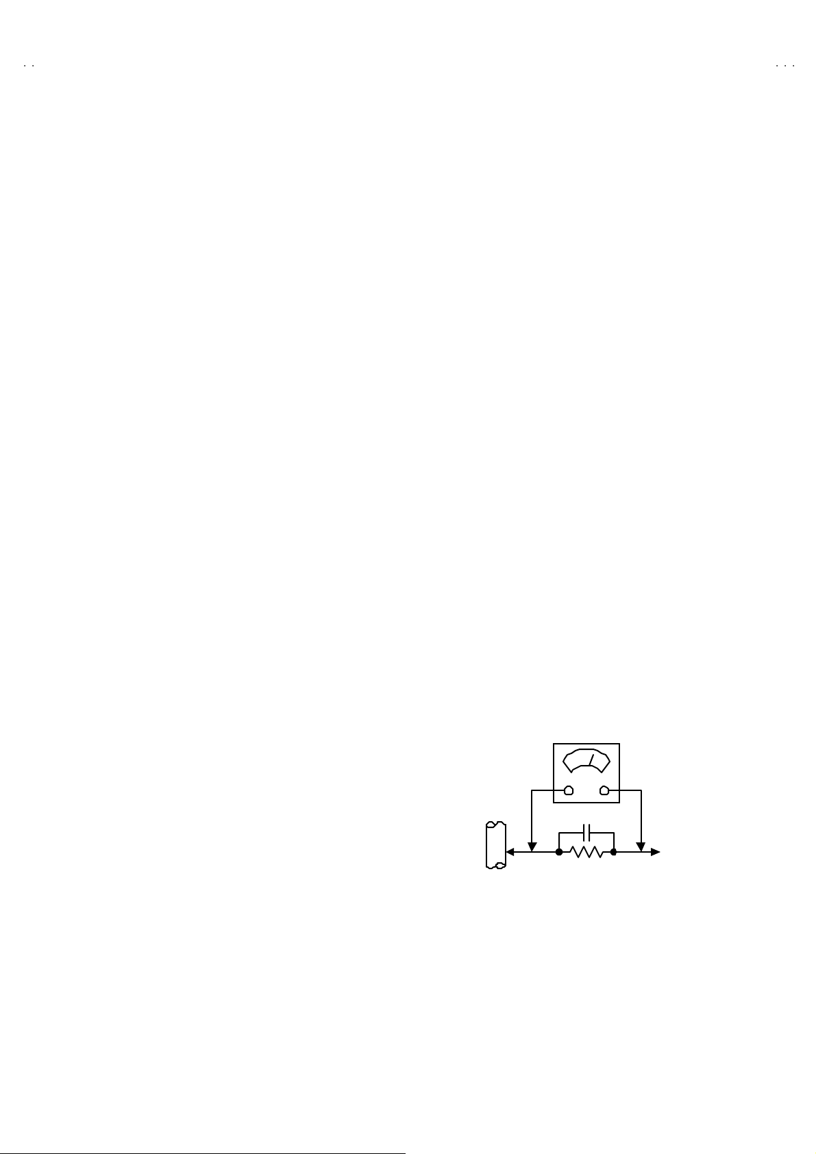
«»»» Alte rn at e Che ck M et hod
Plug th e AC l in e c ord d ir ect ly in to the A C ou tlet ( do n ot us e a li n e
isol ati o n tr an sfor m er dur i ng t hi s che ck .) . Use an AC vo ltmeter
h aving 1 00 0 oh ms pe r vol t or more sens it i vity i n th e fo llow ing
mann er . C on nec t a 1 50 0Ω 10W res ist or par a lle le d b y a 0 .1 5µF
AC-type c apa c it or bet ween an ex po s ed met al pa rt a nd a k no wn
g ood e ar th gr o und ( water pi pe , etc.) . M eas ur e th e A C vo lt ag e
acr oss th e res ist or with th e AC vo l tm eter. Move th e r es istor
con nec tion to e ac h expose d metal par t, p art icul ar l y a ny exp osed
metal p ar t havi n g a r etu rn pat h to the ch assi s, an d m easu r e th e
AC vol tag e ac ross the res ist or . No w , re v er se th e pl u g in th e AC
ou tl et and r e pe at eac h m ea s ur em en t. An y volt ag e me asu re d
must no t e xceed 0 .7 5V AC (r.m. s.) . This c orre sponds to 0.5mA
AC (r.m.s.).
Howeve r, in tropica l are a, this must n ot exce ed 0 .3V AC ( r.m.s.).
This corresponds to 0.2mA AC (r.m.s.).
AC VOLT MET ER
(HAVING 1000 Ω /V,
OR MOR E SENSIT IVITY)
0.15μF AC-T YPE
PLACE THIS PROBE
1500 Ω 10W
GOOD EARTH GROUND
ON E A C H EX PO SE D
ME T AL PA RT
No.52028
3
V-21E3
FEATURES
«
New c h as sis d es i gn en ables us e of an i nt eracti ve on- scr ee n cont ro l.
«
Wide ran ge volt age (1 10V ~240V) AC power input.
« With AUD IO / VI DEO INPUT & OU TPUT te rmi nal.
«
MUT IN G button can red uce th e audi o level to zer o i nst ant ly.
« Func t ion al r em ote co ntrol t o opera te T V set (f or ch annel s e l ect, volume c ontrol, p ow er ON /OFF, etc . ) f rom a d ist anc e.
«
I2C bu s con tr ol ut i lizes singl e chip ICs for IF, V /C , D EF. V SM PRES ET, PR ESET & S ETUP TOU R.
« By m eans of AUTO PR OGRA M, the T V s tati o ns c an b e s electe d autom atica lly a nd the TV cha nn els c an al so b e rearr an ge d aut omatic al ly.
« Built-in ECO MO DE (ECONOM Y, ECOLOGY)
In acco rdanc e with th e br ig ht ness i n a r oo m, th e br ig ht ness and / of con tr ast of th e p icture can b e a djus t ed au tomat ic ally to m ake th e
op ti mu m pictu re which is eas y on th e e ye.
«
Built – in ON TIMER, RETURN + & CHILD LOCK.
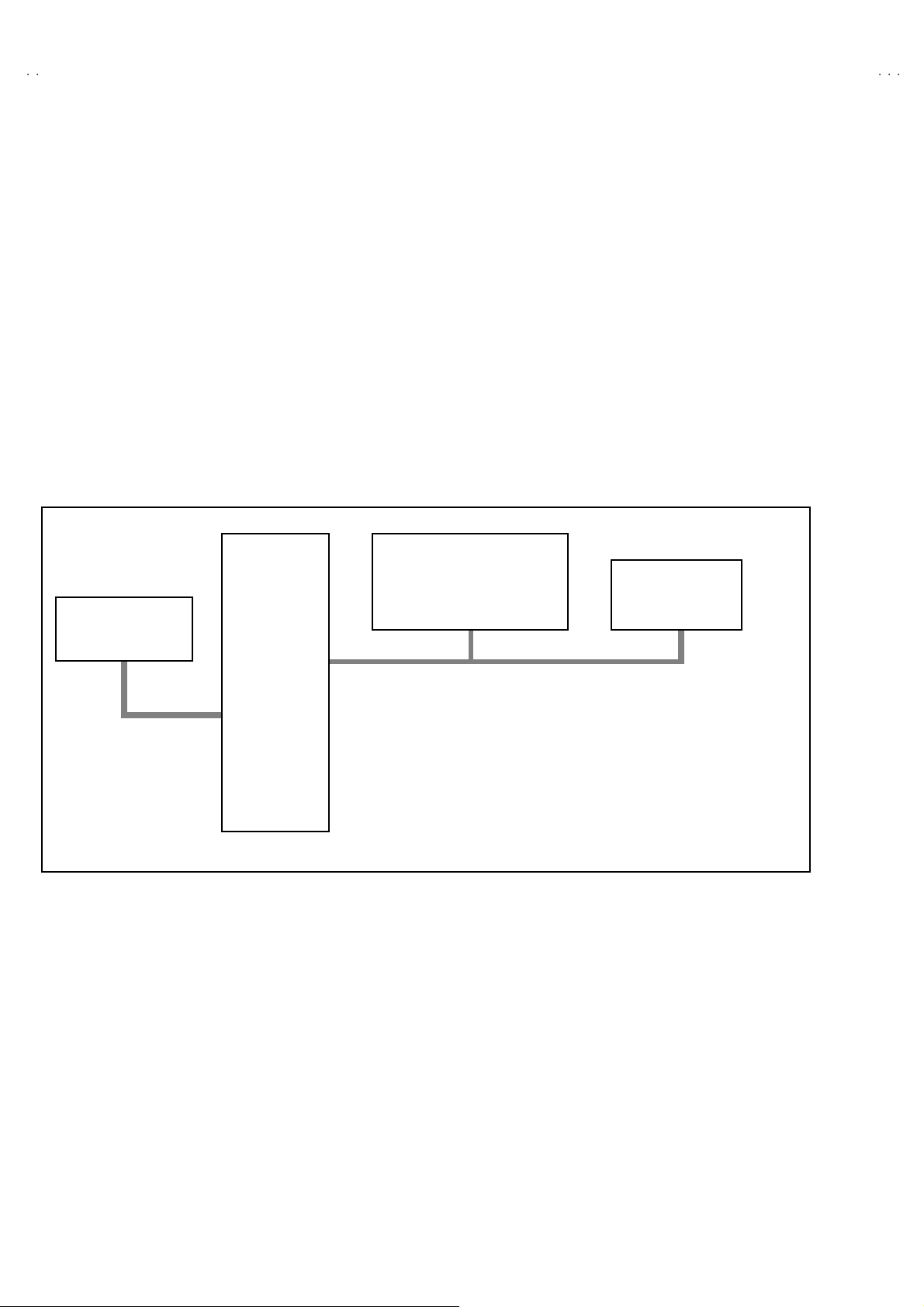
SYSTEM BLOCK DIAGRAM
«
IC702
MEMORY
SCL2/SDA2
IC701
MICRO
COMPUTER
IC301
VIDEO/CHROMA
DECORDER
SCL1/SDA1
TU001
TUNER
4
No. 52028
FUNCTIONS
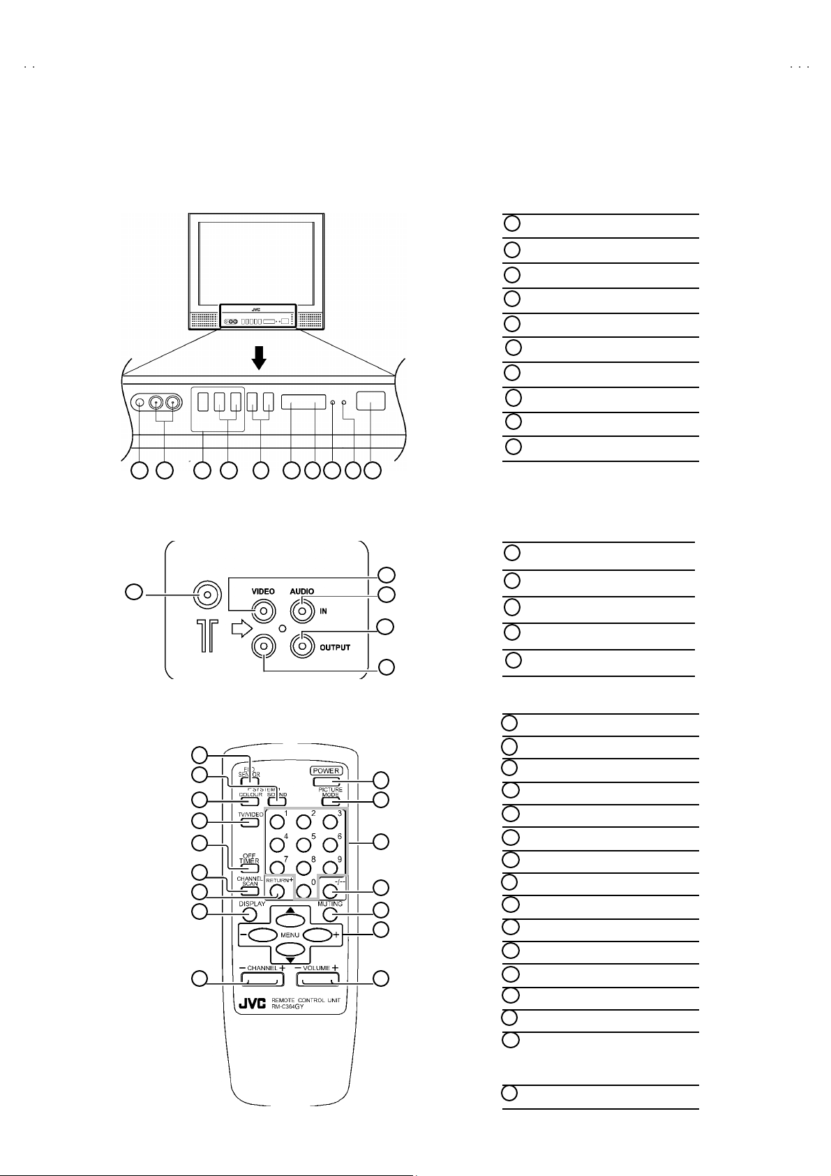
■
FRONT PANEL
10 9 1 2 3 4 5 6 7 8
MENU buttons
1
CHANNEL -/+ buttons
2
VOLUME -/+ bu tto ns
3
AI ECO se nsor
4
REMO TE CON TROL s ens or
5
6
ON TIMER lamp
PO W E R la mp
7
MAIN POWER button
8
9
A/V IN PUT t erminal
10
HEAD PHONE jack
V-21E3
■
REAR TERMINAL
1
■
■
REMOTE CONT RO L UN IT
1
2
3
4
5
6
7
8
9
ANT Terminal
1
2
3
4
5
10
11
12
13
14
15
16
2
VIDEO INPUT Term i nal
3
AUDIO INPUT T ermin al
4
AUDIO OUTPUT Terminal
5
VIDEO OUTPUT Terminal
ECO S ENSOR ke y
1
SOUND SYSTEM key
2
COLO UR SY STEM ke y
3
TV/V IDEO ke y
4
OFF TIMER key
5
CHAN NE L SCAN k ey
6
RETURN+key
7
DISPLAY key
8
CHANNEL key
9
POWER key
10
PICTURE MODE key
11
Number (CH.) key
12
-/--key
13
MUTING ke y
14
MENU ke y
15
MENU ▲/▼ key
MENU -/+ key
VOL UME-/+ key
16
No. 52028
5

V-21E3
SPECIFIC SERVICE INSTRUCTIONS
DISASSEMBLY PROCEDURE
REMOVING THE REAR COVER
1. U np lug the po we r plu g.
$.
$$
!!!!
an d a
2. As s h own in f i gur e , remove t he 5 screws marked
screw marked «
3. R em ov e th e b ack bo ar d an d re mo ve the p ow er c ord f rom th e
rear c over.
4. Withdr a w t he r ear co ver to wa rd you .
«and a s crew m arked ####.
««
REMOVING THE MAIN PW BOARD
» After removing the rear cover.
1. Slight l y raise t he bo th side s of th e M AIN PW Boa rd b y han d and
remove the PW B stop per of MAIN P W Bo ard .
2. Withdr a w t he M AIN PW Boa rd backw ar d.
(If nec ess ar y , take off the w ire cl am p, c onn ect or s etc. )
REMOVING THE SPEAKER
» After removing the rear cover.
1. As s h ow n i n figu r e, remove the 2 screws marke d $
CHECKIN G THE MAIN PW BOARD
1. To c h ec k the back s ide of the PW B oard.
1) Pu ll out the MA IN PW Boar d. (Ref er to RE MO VING THE M AIN
PW B oard)
2) Erec t th e PW Board vert ic al l y so th at you ca n easily check th e
b ack side of the PW B oard.
[CAUTION]
» W hen e re cting th e PW Boar d, be caref ul s o t hat there w ill b e n o
contacting with other PW Board.
» Before turning on power, make sure t hat the CRT earth wire and
oth er c o nne cto r ar e p rope rl y c onnect ed.
WIRE CLAMPIN G AND CABLE T Y ING
1. Be sure to cla mp the wire.
2. Never r em o ve th e c able tie used f or tyi ng the w i re s to gethe r.
Sh oul d i t be inad verte ntly remove d, be su re to ti e th e wi r es with a
new cable tie.
6
No. 52028
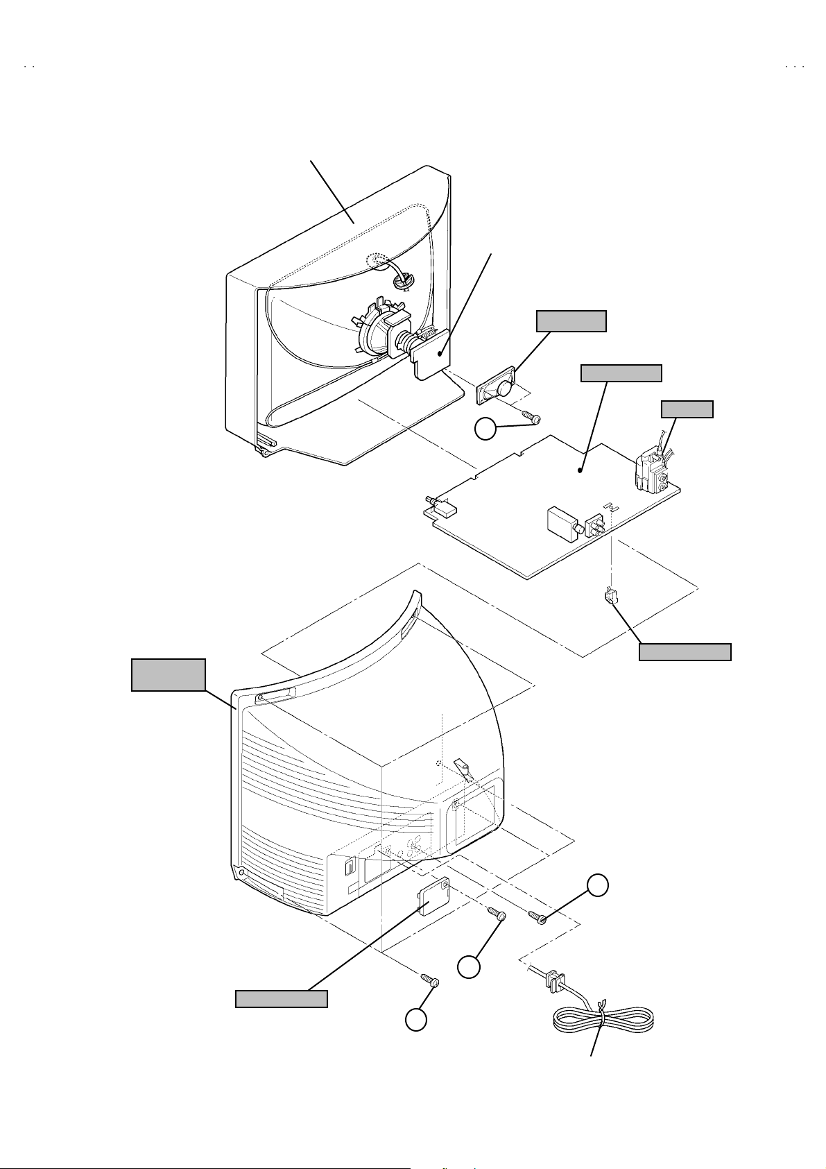
FRONT CABI.
V-21E3
CRT SOCKET
PWB
SP EAKER
MAIN PWB
HV T
D
(××××2)
REAR
COVER
PWB STOPE R
C
(×××× 1)
B
(××××1)
BACK BOARD
A
(×××× 5)
POWER
CORD
No. 52028
7
V-21E3
REPLACEMENT OF MEMORY ICs
1. MEMORY ICs
Thi s m od el u ses me mo r y I Cs. Thi s me mo r y IC da ta ar e f or pr o per opera tion of th e vide o and deflect ion circui ts .
When r ep la cing me m ory IC s, b e s u r e to us e ICs w r it ten wi th t he ini tial v a lu es of dat a.
2. PROCEDURE FOR REPLACIN G MEMORY ICs
(1) Power off
Switch the p ow er of f and di sco nnect t he pow e r pl u g from t he wall out let.
(2) Replace ICs
Be sure to use memory ICs written with the initial data values.
(3) Power on
Connect th e pow er pl u g int o the wal l ou tl et and s witch t he powe r on .
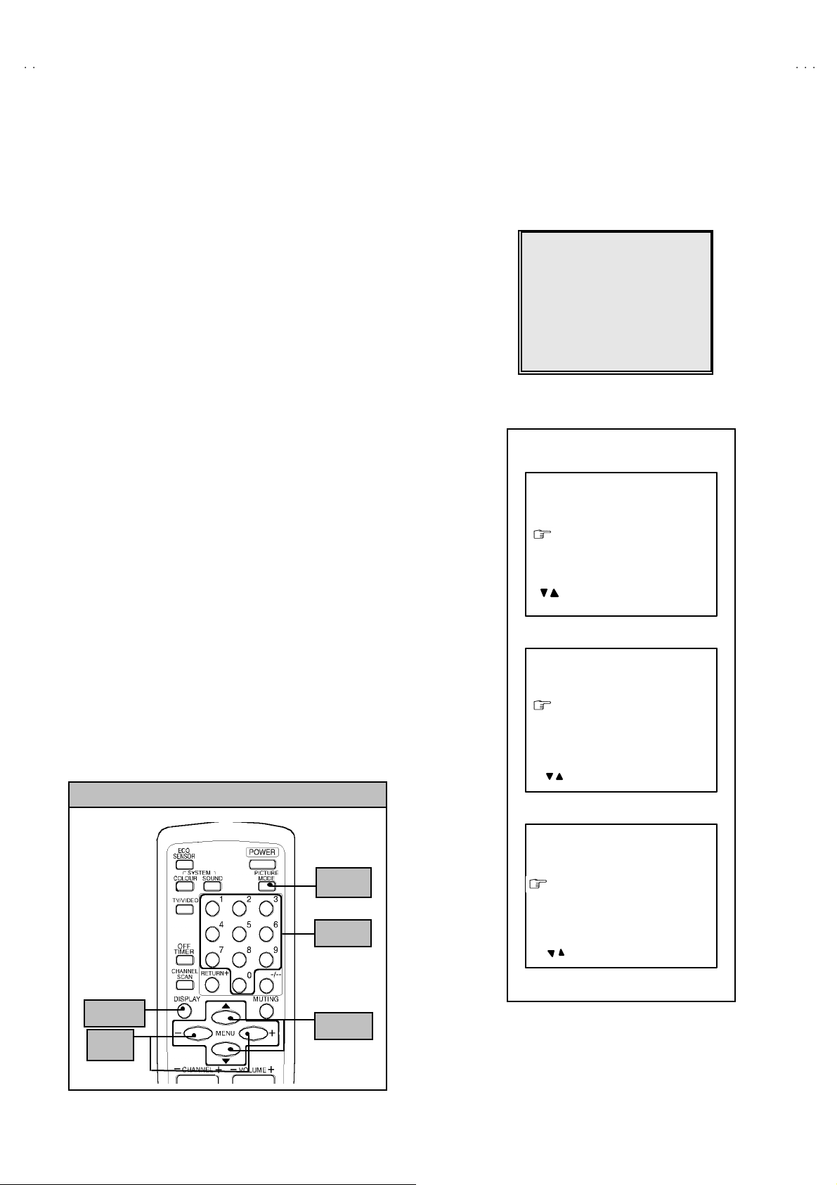
(4) C heck an d set SY STEM CO NSTANT SET
・・・・ It must not adjust without adjustment signals.
1) Press the DI SPLAY ke y and th e PICTURE MODE key of the REMOTE
CONTROL UNIT simultaneously.
2) The SERVICE MENU screen of Fig. 1 will be displayed.
3) W hil e the SE RV ICE MENU is displ ayed , ag ain press the DISPL AY key and
PICTURE MODE ke y si m ul ta neo usly, an d t he S YSTEM CONSTA NT SE T
screen of Fig. 2 will b e displa ye d.
4) C heck th e s ett in g valu es of th e SYS T EM C ON ST A NT SET of T able 1 If th e
valu e is diff er ent, se lect the s ettin g item with th e MENU ▼/▲key, and set
th e co rr ect valu e w ith t he MENU — / + k ey.
5) Press the DI SPLAY k e y tw i ce, and retu rn to th e n ormal sc r ee n.
(5) Receive channel of setting
Refe r to th e OPE R ATI NG INST RUCTIONS and set the r ece ive c ha nn els
(chan nels prese t) as desc r ibe d
(6) User Setting
Check t he us er s ettin g valu e of T ab l e 2, a nd if se tting value is dif feren t, set
th e co rr ect valu e.
For setting , r ef er to the OPE RATING INSTRUCTIO NS.
(7) Setting of SERVICE MENU
Ve rif y the set ti ng it ems of th e SE RVIC E M ENU, and reset w he re n ecess a r y.
For setting , r ef er to the SERVICE ADJUSTMENTS.
KEY ASSIGNMENT OF REMOTE CONTROL UNIT
1.IF 2.V
3.DEF 4.VSM PRESET
5.PRESET
6.SETUP TOUR OFF
1-6 SELECT DISP : EXIT
******
****** *****
************
SYSTEM CONSTA NT SET 1
: SELECT
— / + : OPERATE DISP : EX IT
SYSTEM CONSTA NT SET 2
: SEL — / + : OPE DISP : E XIT/
ERVICE MEN
***** **
* *.****
* * * *
****
********
** ***
** ***** ***
**********
*** ** **
*** ** ** ** ***
*** ** ***** ** **
Fig.1
SY STEM C ON STANT-
R : TRIPLE
BILINGUAL : NO
TUNE R : MU
ECO SENSOR : YES
LANG UAG E : E / R
/
SY STEM C ON STANT- ⅡⅡⅡⅡ
B/B SO UND : OFF
LOCK : 180
COL OUR AU TO : NO
QSS : MINT
ALC : NO
TEXT R ATE : 2 0
SY STEM C ON STANT- ⅢⅢⅢⅢ
ⅠⅠⅠⅠ
PICTURE
MO DE k e y
NUMBERS
SYSTEM CONSTA NT SET 3
AMP TUNER : N
VNR : YES
TEXT TABLE : CYL
VOLUM PWM : POS
key
: SEL — / + : OPE DI SP : EXIT/
DISPLAY
key
MENU
-/+
key
8
MENU
▼/▲ key
No. 52028
Fig.2
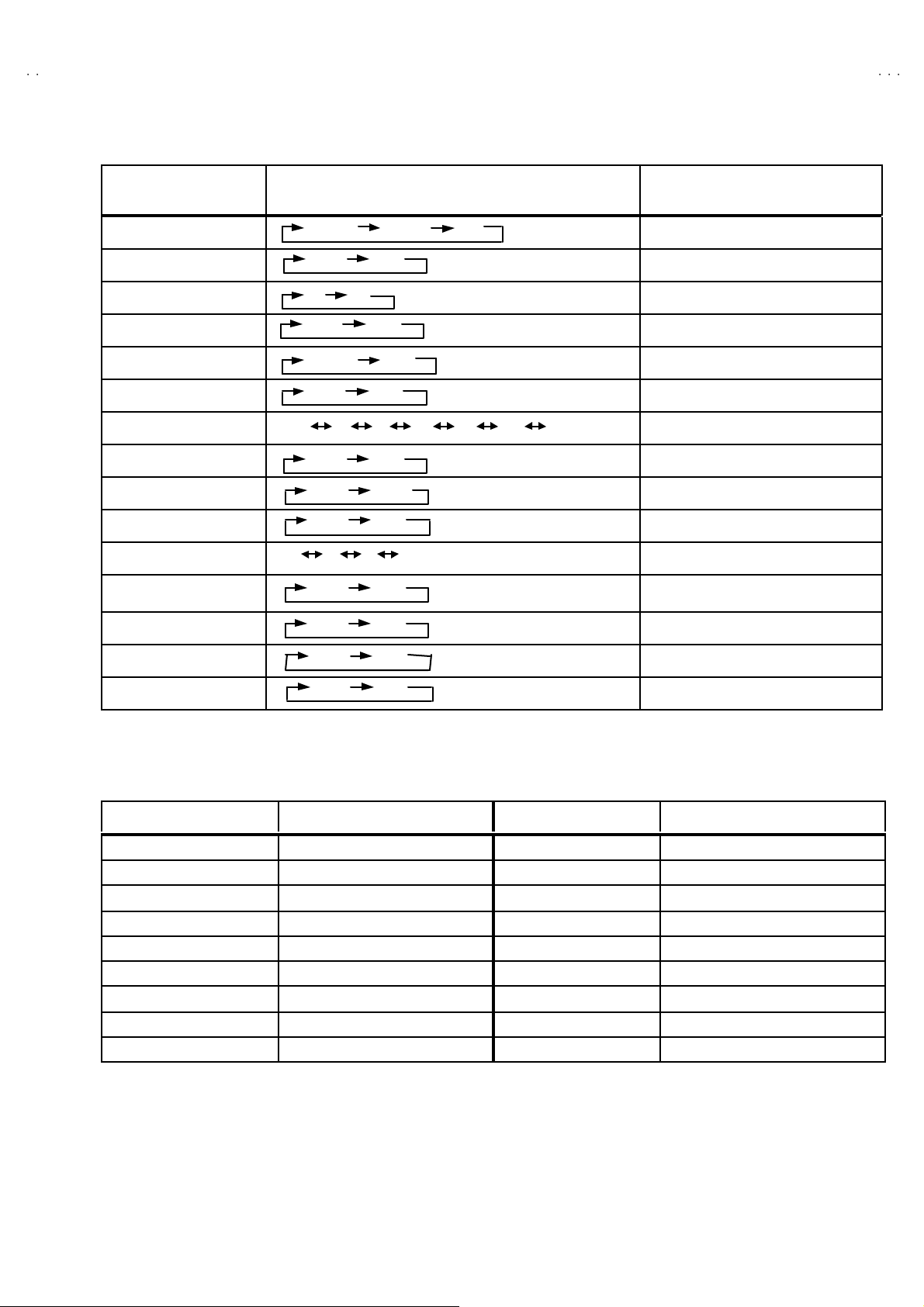
SE TTING OF SY ST EM CONST ANT SET
Setting item Setting contents Setting value
V-21E3
COLOUR
BILINGUAL
TUNER
AI ECO S ENSOR
LA NG UA G E
B/B SOU ND
LO CK
COLOUR AUTO
QSS
ALC
TEXT RATE
AMP TUNER
VNR
TEXT TABLE
VOL UM PW M
MUL TI . PA LTRIPLE
YE S NO
MA
MU
YE S NO
E/R/A /P
ON OFF
YES 10 20 ~ 230 240 250
YE S NO
MI NT MQ SS
YE S NO
10 20 40 80
YE S NO
YE S NO
ARA CYL
POS
E/R
NEG
Table 1
TRIPLE
NO
MU
YE S
E / R
OFF
18 0
NO
MI NT
NO
20
NO
YE S
CYL
POS
USER SE TTING V ALU ES
Setting item Setting value Setting ite m Setting value
SUB POWER ON LANGUAGE ENGLISH
CHA NNEL PO SITIO N 1 PO SITIO N CHA NNEL PRESET Refe r t o OPE RATIN G I NS T RUCTION
VOL UME About 10 AI ECO S EN SOR OFF
TV/V IDEO
ON SCR EEN DI SPLAY
COLOUR SYSTEM PAL ON TIMER PR1 0:00
SOUND SYSTEM B / G BLUE BACK OFF
OFF TIMER OFF OSD.Shows 00 CHI LD LO CK OFF
PICTURE MODE (VSM) BRIGHT SETUP TOUR ON
TV VNR OFF
POSITION IND ICATIO N AUTO SHUTOFF OFF
Table 2
No. 52028
9
Loading…
1
COPYRIGHT © 2002 VICTOR COMPANY OF JAPAN, LTD.
AV—21E3
CONTENTS
!
SPECIFICATIONS ・・・・・・・・・・・・・・・・・・・・・・・・・・・・・・・・
・・・・・・・・・・・・・・・・・・・・・・・・・・・・・・・・・・・・・・・・・・・・・・・・・・・・・・・・・・・・・・・・
・・・・・・・・・・・・・・・・・・・・・・・・・・・・・・・・・・・・・・・・・・・・・・・・・・・・・・・・・・・・・
・・・・・・・・・・・・・・・・・・・・・・・・・・・・・・・・・・・・・・・・・・・・・・・・・・・・・・・・・・
・・・・・・・・・・・・・・・・・・・・・・・・・・・・・ 2
!
SAFETY PRECAUTIONS ・・・・・・・・・・・・・・・・・・・・・・・・・・・・・・・・
・・・・・・・・・・・・・・・・・・・・・・・・・・・・・・・・・・・・・・・・・・・・・・・・・・・・・・・・・・・・・・・・
・・・・・・・・・・・・・・・・・・・・・・・・・・・・・・・・・・・・・・・・・・・・・・・・・・・・・・・
・・・・・・・・・・・・・・・・・・・・・・・・・・・・・・・・・・・・・・・・・・・・・・
・・・・・・・・・・・・・・・・・・・・・・・ 3
! FEATURES・・・・・・・・・・・・・・・・・・・・・・・・・・・・・・・・
・・・・・・・・・・・・・・・・・・・・・・・・・・・・・・・・・・・・・・・・・・・・・・・・・・・・・・・・・・・・・・・・
・・・・・・・・・・・・・・・・・・・・・・・・・・・・・・・・・・・・・・・・・・・・・・・・・・・・・・・・・・・・・・・・
・・・・・・・・・・・・・・・・・・・・・・・・・・・・・・・・・・・・・・・・・・・・・・・・・・・・・・・・・・・・・・・・
・・・・・・・・・・・・・・・・・・・・・・・・・・・・・・・・・・・
・・・・・・
・・・ 4
!
FUNCTIONS ・・・・・・・・・・・・・・・・・・・・・・・・・・・・・・・・
・・・・・・・・・・・・・・・・・・・・・・・・・・・・・・・・・・・・・・・・・・・・・・・・・・・・・・・・・・・・・・・・
・・・・・・・・・・・・・・・・・・・・・・・・・・・・・・・・・・・・・・・・・・・・・・・・・・・・・・・・・・・・・・・・
・・・・・・・・・・・・・・・・・・・・・・・・・・・・・・・・・・・・・・・・・・・・・・・・・・・・・・・・・・・・・・・・
・・・・・・・・・・・・・・・・・・・・・・・・・・・・・・・・・・
・・・・
・・ 5
!
SPECIFIC SERVICE INSTRUCTIONS
・・・・・・・・・・・・・・・・・・・・・・・・・・・・・・・・
・・・・・・・・・・・・・・・・・・・・・・・・・・・・・・・・・・・・・・・・・・・・・・・・・・・・・・・・・・・・・・・・
・・・・・・・・・・・・・・・・・・・・・・・・・・・・・・・・・・・・・・・・・・・・・
・・・・・・・・・・・・・・・・・・・・・・・・・・
・・・・・・・・・・・・・
6
! SERVICE ADJUSTMENTS ・・・・・・・・・・・・・・・・・・・・・・・・・・・・・・・・
・・・・・・・・・・・・・・・・・・・・・・・・・・・・・・・・・・・・・・・・・・・・・・・・・・・・・・・・・・・・・・・・
・・・・・・・・・・・・・・・・・・・・・・・・・・・・・・・・・・・・・・・・・・・・・・・・・・・・・
・・・・・・・・・・・・・・・・・・・・・・・・・・・・・・・・・・・・・・・・・・
・・・・・・・・・・・・・・・・・・・・・ 13
!
PARTS LIST
・・・・・・・・・・・・・・・・・・・・・・・・・・・・・・・・
・・・・・・・・・・・・・・・・・・・・・・・・・・・・・・・・・・・・・・・・・・・・・・・・・・・・・・・・・・・・・・・・
・・・・・・・・・・・・・・・・・・・・・・・・・・・・・・・・・・・・・・・・・・・・・・・・・・・・・・・・・・・・・・・・
・・・・・・・・・・・・・・・・・・・・・・・・・・・・・・・・・・・・・・・・・・・・・・・・・・・・・・・・・・・・・・・・
・・・・・・・・・・・・・・・・・・・・・・・・・・・・・・・・・
・・
・
31
★
OPERATING INSTRUCTIONS
★
STANDARD CIRCUIT DIAGRAM
・・・・・・・・・・・・・・・・・・・・・・・・・・・・・・・・
・・・・・・・・・・・・・・・・・・・・・・・・・・・・・・・・・・・・・・・・・・・・・・・・・・・・・・・・・・・・・・・・
・・・・・・・・・・・・・・・・・・・・・・・・・・・・・・・・・・・・・・・・・・・・・・・・
・・・・・・・・・・・・・・・・・・・・・・・・・・・・・・・・
・・・・・・・・・・・・・・・・
2-1
SERVICE MANUAL
COLOUR TELEVISION
BASIC CHASSIS
CG
Document Download |
‹
›
JVC AV-21E3 Manual Online:
3.2,
2928
votes
JVC AV-21E3 User Manual
JVC AV-21E3 User Guide
JVC AV-21E3 Online Manual
Text of JVC AV-21E3 User Guide:
More Instructions:
|
JVC AV-21E3 Instructions manual
|
DOWNLOAD | |
|
JVC AV-21E3 Instructions manual
|
DOWNLOAD |
Related Products and Documents (TV):
-
JVC AV-28MS1SN TV Instructions manual
AV-28MS1SN
jvc/av-28ms1sn.pdf, 14 -
JVC 0902-NIC-JET TV Instruction manual
0902-NIC-JET
jvc/0902-nic-jet.pdf, 46 -
JVC 1005TNH-II-IM TV Operation & user’s manual
1005TNH-II-IM
jvc/1005tnh-ii-im.pdf, 96 -
JVC AV 27260 TV Operation & user’s manual
AV 27260
jvc/av-27260.pdf, 52 -
JVC AV-28F3SJ TV Instructions manual
AV-28F3SJ
jvc/av-28f3sj.pdf, 17 -
JVC AV-20RM4SE TV Instructions manual
AV-20RM4SE
jvc/av-20rm4se.pdf, 13 -
JVC AV-28T5SP TV Bedienungsanleitung
AV-28T5SP
jvc/av-28t5sp.pdf, 42 -
JVC AV-21PS4N TV Instructions manual
AV-21PS4N
jvc/av-21ps4n.pdf, 14
Comparable Devices:
| # | Manufacturer | Model | Document Type | File | Updated | Pages | Size |
|---|---|---|---|---|---|---|---|
| 1 | LiftMaster | 475M | Owner’s manual | liftmaster/475m-311.pdf | 04 Dec 2024 | 4 | |
| 2 | AEG | 220 D | Installation and operating instructions manual | aeg/220-d-6EP.pdf | 09 Nov 2023 | 17 | 0.13 Mb |
| 3 | RIDGID | R86034 | Operator’s manual | ridgid/r86034-AYC.pdf | 19 Mar 2024 | 28 | 2.53 Mb |
| 4 | Toshiba | W714 | Owner’s manual | toshiba/w714-3FQ.pdf | 29 Dec 2024 | 34 | 0.99 Mb |
| 5 | Dolmar | PC-6414 HappyStart | Instruction and safety manual | dolmar/pc-6414-happystart-436.pdf | 26 May 2024 | 86 | |
| 6 | Samsung | 7418 | Brochure | samsung/7418-1GG.pdf | 22 Mar 2025 | 18 | 0.71 Mb |
Similar Resources:
TV Instructions:
-
Philips Adapter PTA01/00
Philips Product Manual: PTA01/00 PDF Quick start manual — 8FO146
PTA01/00, 2
-
Clas Ohlson Heater FH115-UK
Clas Ohlson Product User Manual: FH115-UK PDF Instruction manual — K6V1TN
FH115-UK, 20
-
GE Cooktop JCJS67
GE Product User Manual: JCJS67 PDF Use and care manual — 8I9378
JCJS67, 31
-
Mitsubishi Air Conditioner MSZ-GA35VA
Mitsubishi MSZ-GA35VA Guide (Doc Type: Air Conditioner Service manual)
MSZ-GA35VA, 32
-
CUMMINS ALLISON Cash Counters & Coin Sorters JetSort LX
Cash Counters & Coin Sorters Operation & user’s manual (CUMMINS ALLISON JetSort LX)
JetSort LX, 38
-
Olympus Digital Camera TG 850
Olympus TG 850 Digital Camera Specifications
TG 850, 4
-
Triad Amplifier RackAmp DSP v2
Amplifier #6Z38Q7
RackAmp DSP v2, 2
-
Samsung Cell Phone SM-M317F/DS
Operation & user’s manual for Samsung SM-M317F/DS Cell Phone
SM-M317F/DS, 170
-
Samsung Monitor 632NWPLUS
Samsung 632NWPLUS Guide (Doc Type: Monitor Operation & user’s manual)
632NWPLUS, 60
-
GE Measuring Instruments PQMII
PDF Guide (@U8F439), GE PQMII Measuring Instruments (15.12.2024)
PQMII, 216
-
Humminbird GPS RF10
Humminbird RF10 GPS Operation manual
RF10, 19
-
NOMA Fan 052-8687-4
Owner’s manual for NOMA 052-8687-4 Fan
052-8687-4, 13
Comments, Questions and Opinions:
JVC AV-21E3 user guide recommended for: AV24WT5EK, 0803-NIC-JMT, AV-28BD5EKI/EKIS, AV-28BD5EP/E, PD-50X575, AA-P30.
The JVC AV-21E3 TV manual (JVC Service manual, 72 pages) is completely safe to download (last scan date: 15/11/2024). You can rest assured of your safety when interacting with JVC AV-21E3 document.
2
VT-1480B
Service manual PDF User Guide (@AR7CB7), Sharp VT-1480B TV (14.03.2025)
110
1448
247
6
32DV60S
Quick use and setup manual Philips TV DVD Combo Quick use and setup manual (File: philips-32dv60s-quick-use-and-setup-manual-8, Mon 11.2024)
8
602
115
7
HL24XK2
Owner’s manual User Guide: Haier HL24XK2 (R24855, Upd.08.02.2025)
23
1324
199
8
LC4.3E
Service manual Philips LC4.3E Guide (Service manual), @Z9SM2Z
92
846
170
- Главная
-
JVC
-
ЭЛТ телевизоры
-
AV-21E3
На этой странице вы найдёте полный список документов на ЭЛТ телевизоры JVC AV-21E3.
Выберите необходимый PDF файл.
-
ЭЛТ телевизоры
JVC AV-21E3 Инструкция по эксплуатацииТип файла
PDFРазмер
414 KbКол-во страниц
24Просмотров
1840Download / Read online
- 1
Другие JVC ЭЛТ телевизоры
-
JVC Interi Art AV-28WFT1EI Инструкция по эксплуатации
PDF файлов
1Просмотров
11654 -
JVC AV28X25EU Инструкция по эксплуатации
PDF файлов
1Просмотров
8940 -
JVC AV32H20EU Инструкция по эксплуатации
PDF файлов
1Просмотров
8553 -
JVC INTERIART PREMIERE, INTERIART MUSEE HV-29WZ Инструкция по эксплуатации
PDF файлов
1Просмотров
7150 -
JVC AV32X25EU Инструкция по эксплуатации
PDF файлов
1Просмотров
5819 -
JVC AV28WT5EP Инструкция по эксплуатации
PDF файлов
1Просмотров
5328
Другие устройства JVC
-
Автомобильные видеосистемы
JVC KW-NX7000 Руководство пользователяPDF файлов
5Просмотров
36680 -
Цифровые ресиверы
JVC KD-X50BT Руководство пользователяPDF файлов
4Просмотров
32466 -
Ресиверы
JVC KW-NX7000BT Руководство пользователяPDF файлов
4Просмотров
21677 -
Ресиверы
JVC KW-AVX640 Руководство пользователяPDF файлов
5Просмотров
21597 -
Ресиверы
JVC KW-NT300 Руководство пользователяPDF файлов
4Просмотров
21518 -
DVD-плееры
JVC KD-NX5000- Руководство пользователяPDF файлов
3Просмотров
20845
Ранее вы смотрели
Производители
Agatec
Aqua Products
Cambridge Audio
Crown Equipment
Dayva International
Koblenz/Thorne Electric
LEGO Education
Master Bilt
Midea
Red Digital Cinema
Типы устройств
Сканеры штрих-кодов
Сварочные аппараты
Аксессуары для планшетов и смартфонов
Системы дистанционного запуска с помощью смартфона
Пульты дистанционного управления
Сигнализации
Система гриля
Прожекторы
Сигнальные процессоры
Точки доступа
Устройства
Accusplit Eagle AE1590
Electrolux CABRIO 291
Hayter Mowers Motif 435G
Heatcraft Refrigeration Products SWN0200H2C
Kenmore 10659069993
Olympus FE-310
Pentax A30E
QSC PLX 1802
Riverstone Networks 9000
Victor 1240-3A
freeuserguide.ru
About Us
Contacts
Disclamers
Privacy Policy
Эта страница полезна для вас? Поделитесь ссылкой: