
Отклонения от заданной температуры процесса оказывают непосредственное влияние на свойства производимых пищевых продуктов. Таким образом, контроль/ мониторинг температуры является одним из решающих факторов в пищевой промышленности.
Особенно важным является контроль этого параметра во всех установках, где все зависит от того, чтобы определенный диапазон температур не был превышен и не был ниже минимально допустимого значения, в противном случае, конечный продукт будет необратимо испорчен.
Пример:
поддержание равномерной температуры шоколадной массы.
Чтобы избежать такого рода необратимых повреждений, JUMO предлагает Вам электронные или электромеханические термостаты, которые будут постоянно следить за температурным режимом Вашей системы.
Основные преимущества:
если достигается максимальная и минимальная температура системы или устройства, термостаты, утвержденные согласно DIN EN 14597, отключат нагрев или охлаждение и переведут систему в безопасный режим.
Содержание
- JUMO 701150 14597 safetyM STB/STW — Safety Temperature Limiter and Safety Temperature Monitor Data Sheet User Manual
- Stb/stw, Brief description, Block diagram
- Регуляторы-ограничители температуры safetyM STB/STW тип 701150/55, safetyM TB/TW тип 701160
- Скачать
- Информация по Госреестру
- Назначение
- Описание
- Программное обеспечение
- Инструкция по эксплуатации JUMO 60.3035 Surface-mounting single or twin thermostat, ATH-SW Operating Manual
- Введение / применение, Определение устройства / декларация типов, Размеры
- JUMO safetyM STB/STW — Safety temperature limiter and safety temperature monitor according to DIN EN 14597 (701150)
- Features
- Applications
- Переключательная функция, Технические данные, Электрические параметры – Инструкция по эксплуатации JUMO 604100 frostTHERM-AT/-DR Data Sheet
- Страница 2
JUMO 701150 14597 safetyM STB/STW — Safety Temperature Limiter and Safety Temperature Monitor Data Sheet User Manual
Stb/stw, Brief description, Block diagram

JUMO GmbH & Co. KG
Delivery address: Mackenrodtstraße 14
36039 Fulda, Germany
36035 Fulda, Germany
JUMO Instrument Co. Ltd.
JUMO House
Temple Bank, Riverway
Harlow, Essex CM20 2DY, UK
Phone: +44 1279 635533
Fax:
JUMO Process Control, Inc.
8 Technology Boulevard
Canastota, NY 13032, USA
Phone: 315-697-5866
JUMO safetyM STB/STW
Safety Temperature Limiter,
Safety Temperature Monitor
According to DIN EN 14597
Brief description
The safety temperature limiter JUMO safetyM STB and the safety temperature monitor JUMO
safetyM STW are used to reliably detect and avert hazards that could cause injuries to people,
that could be harmful to the environment, or that could cause destruction of production plants
and produced goods at an early stage.
Its primary task is to reliably monitor thermal processes and switch the systems to an opera-
tional safe status in the event of malfunctions.
The measured value at the analog input can be recorded by various probes or standard sig-
nals. The exceedance of the limit value is indicated by the installed LEDs K1 and K2 (red) for
each channel, and the installed relay output alarm switches the system to an operational safe
status (alarm range).
The high standards of DIN EN 61508 and DIN EN ISO 13849 are met by a device concept that
has a 1oo2D structure (2-channel structure with diagnostic channel) which ensures reliable de-
tection of errors. This device concept can also be used for applications that correspond to the
new machinery directive 2006/42/EC.
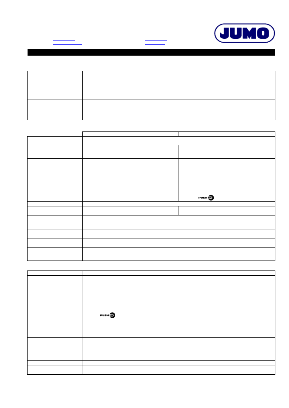
Block diagram
1 binary input
for floating contact
1 analog output
standard signal
Voltage supply
AC 110 to 240 V +10/-15 %, 48 to 63 Hz
AC/DC 20 to 30 V, 48 to 63 Hz
USB Interface
for setup program
1 relay Output Alarm
SPDT (changeover contact)
with fuse cut-out
1 relay output pre-alarm KV)
SPDT (changeover contact)
LCD display
with white background lighting
4 keys
for operation and
acknowledgement of alarms
Mesured Value
universal analog Input 1
universal analog Input 2
Data Sheet 701150
Type 701150/ …
Special features
k 1oo2D structure for a high degree of pro-
cess safety and reliability
k LCD display with background lighting
and plain text display for more comfortable
operation
k Setup program for configuration and
archiving via USB interface
k Digital input filter with adjustable
filter time constant
k Pre-alarm absolute or adjustable as a mar-
gin from the limit value
k Wide voltage supply range
from AC 110 to 240 V +10 %/-15 % or
AC/DC 20 to 30 V
k Can be configured as STB or STW
k 12 linearizations can be set
k Internal and external unlocking possible
k Approvals for DIN EN 14597, SIL, PL (Per-
Источник
Регуляторы-ограничители температуры safetyM STB/STW тип 701150/55, safetyM TB/TW тип 701160
| Номер в ГРСИ РФ: | 58547-14 |
|---|---|
| Производитель / заявитель: | Фирма «JUMO GmbH & Co. KG», Германия |
Регуляторы-ограничители температуры safetyM STB/STW тип 701150/55, safetyM TB/TW тип 701160 (далее — регуляторы) предназначены для измерений аналоговых выходных сигналов датчиков в виде напряжения и силы постоянного тока, сопротивления (в том числе сигналов от термопар и термопреобразователей сопротивления), измерительных преобразований измеренных значений физической величины в унифицированный аналоговый сигнал силы или напряжения постоянного тока, в дискретный или релейный сигнал, отображения результата измерений на цифровом индикаторе, а также для регулирования измеряемой физической величины по заданному закону.
Скачать
Информация по Госреестру
| Основные данные | |
|---|---|
| Номер по Госреестру | 58547-14 |
| Наименование | Регуляторы-ограничители температуры |
| Модель | safetyM STB/STW тип 701150/55, safetyM TB/TW тип 701160 |
| Год регистрации | 2014 |
| Методика поверки / информация о поверке | МП 58547-14 |
| Межповерочный интервал / Периодичность поверки | 3 года |
| Страна-производитель | Германия |
| Информация о сертификате | |
| Срок действия сертификата | 25.09.2019 |
| Тип сертификата (C — серия/E — партия) | C |
| Дата протокола | Приказ 1376 п. 06 от 25.09.2014 |
Производитель / Заявитель
Фирма «JUMO GmbH & Co. KG», Германия
Назначение
Регуляторы-ограничители температуры safetyM STB/STW тип 701150/55, safetyM TB/TW тип 701160 (далее — регуляторы) предназначены для измерений аналоговых выходных сигналов датчиков в виде напряжения и силы постоянного тока, сопротивления (в том числе сигналов от термопар и термопреобразователей сопротивления), измерительных преобразований измеренных значений физической величины в унифицированный аналоговый сигнал силы или напряжения постоянного тока, в дискретный или релейный сигнал, отображения результата измерений на цифровом индикаторе, а также для регулирования измеряемой физической величины по заданному закону.
Описание
Принцип действия регуляторов основан на измерении и обработке микропроцессором поступающих на его вход аналоговых сигналов, сравнении с заданными пользователем параметрами управления и выдачи сигналов управления внешними исполнительными устройствами.
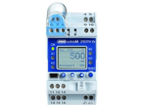
Регуляторы выполнены в пластиковом корпусе. На лицевой панели регуляторов имеются кнопки управления параметрами входных сигналов, кнопка сброса, светодиоды рабочего состояния, аварийного режима, ошибок. Также на лицевой стороне регуляторов расположен монохроматический дисплей, разъемы для подключения к персональному компьютеру (у регуляторов safetyM STB/STW тип 701150/55 разъём мини USB, у регуляторов TB/TW тип 701160 разъём — четырёхполюсное гнездо для подключения адаптера USB/TTL). На боковой стороне регуляторов расположены клеммы для подключения напряжения питания и входных сигналов.
Конфигурирование приборов (параметры входных сигналов и параметры индикации текущих значений входных сигналов и т.д.) проводится с использованием клавиш на передней панели.
Фотографии общего вида регуляторов приведены на рисунках 1 и 2.
Рисунок 1 — Фото общего вида регулятора Рисунок 1 — Фото общего вида регулятора 701150/55 701160
Программное обеспечение
Программное обеспечение (ПО) регуляторов представляет собой встроенное программное обеспечение (ВПО), идентификационные данные которого описаны в таблице 1.
ВПО является метрологически значимой частью ПО, оно устанавливается в энергонезависимую память регуляторов в производственном цикле на заводе-изготовителе; в процессе эксплуатации доступ к ВПО отсутствует (уровень защиты «средний» в соответствии с Р 50.2.077-2014). Метрологические характеристики регуляторов нормированы с учетом ВПО.
ВПО, указанное в таблице 1, обеспечивает ограничение прав доступа к настроечным параметрам и измерительной информации с помощью пароля. Кроме того, у регуляторов тип 701150/55 для предотвращения непреднамеренных и преднамеренных изменений настроек имеется прозрачная крышка с двумя отверстиями, через которые вставляется проволока, соединяющая крышку и корпус. Концы проволоки фиксируются пломбой.
Источник
Инструкция по эксплуатации JUMO 60.3035 Surface-mounting single or twin thermostat, ATH-SW Operating Manual
Введение / применение, Определение устройства / декларация типов, Размеры

Прочитайте эту инструкцию по эксплуатации до начала работы с
устройством. Храните инструкцию в месте, доступном для всех
пользователей в любое время. Мы просим вас оказать нам содействие
в улучшении этой инструкции по эксплуатации. Мы будем благодарны
за любые ваши советы.
В этой инструкции по эксплуатации содержится информация о всех
необходимых настройках и о возможном вмешательстве во
внутреннюю конструкцию устройства. Если несмотря на это при вводе в
эксплуатацию возникнут сложности, мы просим вас воздержаться от
осуществления недозволенных манипуляций в устройстве. Тем самым
вы теряете право на проведение гарантийного ремонта! Свяжитесь с
ближайшим филиалом изготовителя или с нашим головным офисом.
Устройства не требуют технического обслуживания. В случае
возникновения неисправности мы просим вас отправить устройство
фирме-поставщику с точным описанием неисправности. Сотрудники
наших отделений, филиалов и представительств в любой момент
предоставят вам консультацию и техническую поддержку.
JUMO GmbH & Co. KG
Юр. адрес:
36039 Fulda, Germany
Адрес дост.: Mackenrodtstraße 14
36039 Fulda, Germany
Почт. адрес: 36035 Fulda, Germany
1. Введение / применение
Навесные термостаты типового ряда ATH-SW допущены для работы в
■ реле температуры (TW)
■ предохранительных ограничителей температуры (STB)
■ предохранительных реле температуры STW (STB)
■ Типовое испытание согласно:
— Директиве по аппаратам, работающим под давлением 97/23/ЕС (все типы
кроме ATH.-SW-2 и ATH.-SW-22)
Указания по технике безопасности
Физические и токсикологические свойства веществ, выделение которых может
Источник
JUMO safetyM STB/STW — Safety temperature limiter and safety temperature monitor according to DIN EN 14597 (701150)
Features
- Can be configured as safety temperature limiter (STB) or safety temperature monitor (STW)
- 1oo2D architecture
- Approvals for DIN EN 14597, SIL, PL (Performance Level), UL
- Two relay outputs can be used as pre-alarm or limit value alarm
- Pre-alarm absolute or adjustable as a margin from the limit value
- LCD display with background lighting and plain text display
- Setup program for configuration and archiving via USB interface
- Wide voltage supply range from 110 to 240 V +10 %/-15 % or ACDC 20 to 30 V
- Internal and external unlocking possible
Applications
Monitoring and limiting of temperature, pressure, and other process variables — e.g.:
- Fuse protection for burner control
- Monitoring of heating elements
- Protection for heat transfer oil systems
- Protection of boiler plants
- Level monitoring
Description
The safety temperature limiter (STB) and safety temperature monitor (STW) enable early and reliable detection of risks which could potentially result in personal injuries, environmental damage, or destruction of the production plant and production materials.
Its primary task is to reliably monitor thermal processes and to switch plants to a safe operating status in the event of malfunctions.
The measured value at the analog input can be recorded by various probes or standard signals. Limit value exceedance is indicated by the installed LED K1 and K2 (red) for each channel and the integrated alarm relay output switches the plant to safe operating status (alarm range).
The device concept meets the stringent requirements of DIN EN 61508 and DIN EN 13849. The 1oo2D structure ensures reliable detection of faults, meaning that the device concept can also be used for applications subject to the new Machinery Directive 2006/42/EC.
Protective, regulation, and control devices
Safety temperature monitor (STW)
Protective temperature monitor with automatic reset for heat-generating plants. An automatic reset occurs upon activation after the probe temperature has risen or fallen above/below the set limit value by the amount of the switching differential.
(Modes of operation 2B, 2K, and 2P)
Safety temperature limiter (STB)
Protective temperature limiter for heat-generating plants that can only be reset manually or with a tool.
(Functions 2B, 2J, 2 V, 2K, 2P and adjustable with special tool)
Источник
Переключательная функция, Технические данные, Электрические параметры – Инструкция по эксплуатации JUMO 604100 frostTHERM-AT/-DR Data Sheet
Страница 2
JUMO GmbH & Co. KG
P.O. Box 1209
D-36039 Fulda, Germany
Telefon:
+49 661 6003 321
+49 661 6003 9695
Представительство в России
Фирма «ЮМО», г. Москва, 115162
ул. Люсиновская, 70, стр. 5
Тел:
+7 495 961 32 44; 954 11 10
+7 495 954 69 06
Типовой лист 604100
Переключательная функция
Предохранительное
термореле STW
Если темобаллон длиной в 15 см при 3 м, 30 см при 6 м и 40 см при длине 12 м охлаждается больше
установленного заданного значения, благодаря переключающемуся реле электрическая цепь 1-2
размыкается, электрическая цепь 1-4 замыкается. При повышении температуры микровыключатель
автоматически переходит в исходную позицию
В случае разрушения
измерительной системы, т.е. если расширяющаяся жидкость отсутствует,
давление на мембрану падает,
и электрическая цепь остается постоянно разомкнутой.
Предохранительный
ограничитель
температуры STB
При падении температуры предохранительный ограничитель автоматически блокирует цепь, и
восстановить коммутацию после повышения температуры возможно только вручную.
В случае разрушения измерительной системы, т.е. если расширяющаяся жидкость отсутствует,
давление на мембрану падает, и электрическая цепь остается постоянно разомкнутой.
Технические данные
Конструктивное исполнение 5
Конструктивное исполнение 7
Нижняя часть корпуса:
Полиамид (армированный)
серебристо-серый по шкале RAL 7001
Крышка корпуса: Полистирол со смотровым
окошком (оргстекло)
Цвет: Кобальтовый по шкале RAL 5013
Установка заданного
значения
Точка переключения выставляется с помощью
отвертки при снятой
осуществляется через смотровое окошко.
Точка переключения выставляется с помощью
отвертки.
Степень защиты
IP 40 по стандарту EN 60 529
IP 65 по стандарту EN 60 529 (TZ 404)
IP 20 по стандарту EN 60 529
Электрическое
подключение
Резбовой кабельный ввод М20х 1,5, для кабеля ø
Присоединение кабеля непосредственно к
примерно 2,4 мм (или 9,5 мм с капилляром 1,8 м)
Вариант установки
корпуса
На стене/ на трубе
на DIN-рейку ТН35, стандарт DIN EN 60715
допустимая температура
хранения
допустимые окружающие
условия для корпуса
Окружающая температура должна быть на +2°C выше, чем значение точки переключения.
допустимая максимальная
температура темобаллона
допустимый
минимальный радиус
изгиба капилляра
Электрические параметры
Электрический контакт
мгновенный выключатель с однополюсным переключающим контактом
Коммутационная
способность
Предохранительное термореле (STW)
Предохранительный ограничитель температуры
(STB)
На размыкающем контакте (цепь контакта 1-2):
AC 230 В +10 %, 16 (2,5) A, cos cp = 1 (0,6),
DC 230 В+10 %, 0,25 A
На замыкающем контакте (цепь контакта 1-4):
AC 230 В +10 %, 6,3 (2,5) A, cos (p = 1 (0,6),
DC 230 В+10 %, 0,25 A
На размыкающем контакте (цепь контакта 1-2)
AC 230 В+10 %, 16 (2,5) A, cos cp= 1 (0,6),
DC 230 В+10 %, 0,25 A
На сигнальном контакте (цепь контакта 1-4):
AC 230 В +10 %, 2 (04) A, cos cp = 1 (0,6),
DC 230 В+10 %, 0,25 A
Электрическое
подключение
Зажимы „Push-In®»: запатентованное зажимное присоединение компании Weidmüller GmbH & Co. KG,
Детмольд, Германия.
Сечение соединительного
провода
тонкопроволочный (однопроволочный, тонкопроволочный с кабельным зажимом)
Надежность срабатывания
Для обеспечения максимальной
надежности переключения рекомендуется поддерживать
следующую минимальная нагрузка:
AC / DC = 24 В, 100 мА для серебряных контактов
Погрешность настройки
точки переключения
Зона неоднозначности
Заводские настройки для
точки переключения
Источник
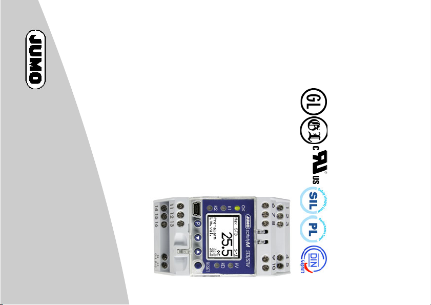
Safety temperature limiter, safety temperature monitor according to DIN EN 14597
JUMO safetyM STB/STW
Technical data
Downloads
No related documents found.
Accessories
Safety temperature limiter, safety temperature monitor according to DIN EN 14597
JUMO safetyM STB/STW
Reorder
Only our standard web articles can be sold online and are available in our product configurator. Please use our product request inquiry form if you cannot find the article you are looking for.
Products in your inquiry list
Your request to us
Salutation
Ms.
Mr.
Dies ist ein Pflichtfeld.
First Name
This is a mandatory field. Please enter a first name.
Last Name
This is a mandatory field. Please enter a surname.
Company Name
This is a mandatory field. Please enter your company name.
Position/Field
Please select an option
Street
This is a mandatory field. Please enter a street.
Postcode
This is a mandatory field. Please enter a postal code.
City
This is a mandatory field. Please enter a city.
Country
Please select an option
Phone
This is a mandatory field. Please enter a telephone number.
This is a mandatory field. Please enter your email address.
Message
recaptcha
mtc tag
utm-source
With my request I agree that my data will be stored and that JUMO GmbH & Co. KG contacts me for information purposes. I can revoke the storage of my data at any time.
I have read and agree to the privacy policy.
With your inquiry you set us a task which we would like to fulfil to your satisfaction. The data collected in this context is stored. In order to process your request satisfactorily it is necessary to fill in all available fields (only fields marked with * are mandatory) We use your data to process your request as part of the business process. Personal data will not be treated. In particular, we do not pass on any data to third parties. We reserve the right to statistically evaluate anonymous data records.
- Структура 1oo2D – обеспечивает высокий стандарт безопасности процесса
- Упрощающий управление текстовый ЖК-дисплей с фоновой подсветкой
- Setup-Программа для конфигурирования и архивации через USB-Интерфейс
- Цифровой входной фильтр с задаваемой временной константой
- Предварительная тревога как абсолютное значение или как отступ от предельного значения
- Широкий диапазон электропитания AC 110 … 240 В +10 %/-15 % или AC/DC 20 … 30 В
- Может конфигурироваться как STB или STW
- 12 настраиваемых линеаризаций
- Внутренняя или внешняя Разблокировка
- Соответсвие DIN EN 14597, SIL, PL (Performance-Level)
- Допуска UL, GL в процессе получения
Описание
Применение предохранительного ограничителя температуры (STB) и предохранительного реле температуры (STW) позволяет заблаговременно распознать и предотвратить опасности, которые могут привести к увечью людей, причинению ущерба окружающей среде или разрушению производственных установок и промежуточных изделий.
Главной задачей приборов является надежный контроль теплотехнических процессов и приведение установок в безопасное рабочее состояние при неисправностях. Измеряемое значение на аналоговом входе может быть получено с разных датчиков или через унифицированные сигналы.
Устройство контроля предельного значения имеет сигнализацию посредством светодиодов К1 и К2 (красный) для каждого канала, а встроенное реле тревоги приводит установку в безопасное состояние (в диапазоне тревог).
Высокие требования DIN EN 61508 как и DIN EN ISO 13849 выполняются благодаря концепции прибора, конструкция которого (1oo2D: 2-канальная структура с диагностическим каналом) гарантирует надежное обнаружение ошибок, поэтому может применяться также и в сферах, требующих соблюдения директивы по машиностроению 2006/42/ЕС.
- Аналогичные товары
Вся информация на сайте о товарах и ценах носит справочный характер и не является публичной офертой. Производитель оставляет за собой право изменять характеристики товара, его внешний вид и комплектность без предварительного уведомления продавца
2014-05-01
/00564764
(translation of the German
Operating Manual
original manual)
B 701150.0
according to DIN EN 14597
safety temperature monitor
JUMO safetyM STB/STW
Safety temperature limiter,
Operating overview

Operating overview . . . . . . . . . . . . . . . . . . . . . . . . . . . . . . . . . . . . . . . . . . . . . . . . . . . . . . . . . . . 2
1 Brief description . . . . . . . . . . . . . . . . . . . . . . . . . . . . . . . . . . . . . . . . . . . . . . . . . . . . . . . . . . . . 10
1.1 Safety temperature monitor (STW) . . . . . . . . . . . . . . . . . . . . . . . . . . . . . . . . . . . . . . . . . . . . . . . . . . . . .10
1.2 Safety temperature limiter (STB). . . . . . . . . . . . . . . . . . . . . . . . . . . . . . . . . . . . . . . . . . . . . . . . . . . . . . .10
1.3 Safety information. . . . . . . . . . . . . . . . . . . . . . . . . . . . . . . . . . . . . . . . . . . . . . . . . . . . . . . . . . . . . . . . . .11
2 Identifying the device version . . . . . . . . . . . . . . . . . . . . . . . . . . . . . . . . . . . . . . . . . . . . . . . . . 12
2.1 Scope of delivery . . . . . . . . . . . . . . . . . . . . . . . . . . . . . . . . . . . . . . . . . . . . . . . . . . . . . . . . . . . . . . . . . .14
2.2 Device software versions . . . . . . . . . . . . . . . . . . . . . . . . . . . . . . . . . . . . . . . . . . . . . . . . . . . . . . . . . . . .15
2.3 Serial number . . . . . . . . . . . . . . . . . . . . . . . . . . . . . . . . . . . . . . . . . . . . . . . . . . . . . . . . . . . . . . . . . . . . .15
2.4 Service addresses . . . . . . . . . . . . . . . . . . . . . . . . . . . . . . . . . . . . . . . . . . . . . . . . . . . . . . . . . . . . . . . . .15
3 Installation . . . . . . . . . . . . . . . . . . . . . . . . . . . . . . . . . . . . . . . . . . . . . . . . . . . . . . . . . . . . . . . . . 17
3.1 Dimensions . . . . . . . . . . . . . . . . . . . . . . . . . . . . . . . . . . . . . . . . . . . . . . . . . . . . . . . . . . . . . . . . . . . . . . .17
3.2 Installation location, DIN rail installation. . . . . . . . . . . . . . . . . . . . . . . . . . . . . . . . . . . . . . . . . . . . . . . . .18
3.3 Close mounting. . . . . . . . . . . . . . . . . . . . . . . . . . . . . . . . . . . . . . . . . . . . . . . . . . . . . . . . . . . . . . . . . . . .18
3.4 Dismantling . . . . . . . . . . . . . . . . . . . . . . . . . . . . . . . . . . . . . . . . . . . . . . . . . . . . . . . . . . . . . . . . . . . . . . .19
3.5 Electrical isolation. . . . . . . . . . . . . . . . . . . . . . . . . . . . . . . . . . . . . . . . . . . . . . . . . . . . . . . . . . . . . . . . . .20
3.6 Use of the setup interface . . . . . . . . . . . . . . . . . . . . . . . . . . . . . . . . . . . . . . . . . . . . . . . . . . . . . . . . . . .20
4 Electrical connection . . . . . . . . . . . . . . . . . . . . . . . . . . . . . . . . . . . . . . . . . . . . . . . . . . . . . . . . 21
4.1 Installation notes. . . . . . . . . . . . . . . . . . . . . . . . . . . . . . . . . . . . . . . . . . . . . . . . . . . . . . . . . . . . . . . . . . .21
4.2 Connection diagram . . . . . . . . . . . . . . . . . . . . . . . . . . . . . . . . . . . . . . . . . . . . . . . . . . . . . . . . . . . . . . . .23
5 Commissioning the device . . . . . . . . . . . . . . . . . . . . . . . . . . . . . . . . . . . . . . . . . . . . . . . . . . . . 27
5.1 Display and operating elements . . . . . . . . . . . . . . . . . . . . . . . . . . . . . . . . . . . . . . . . . . . . . . . . . . . . . . .27
5.2 Setting the display after switch-on . . . . . . . . . . . . . . . . . . . . . . . . . . . . . . . . . . . . . . . . . . . . . . . . . . . . .27
Inhalt

Inhalt
5.3 Selecting and editing parameters (plausibility inquiry for input values) . . . . . . . . . . . . . . . . . . . . . . . . .29
5.4 Aborting edit . . . . . . . . . . . . . . . . . . . . . . . . . . . . . . . . . . . . . . . . . . . . . . . . . . . . . . . . . . . . . . . . . . . . . .30
5.5 Alarm acknowledgement using the Reset key (only for temperature limiters STB) . . . . . . . . . . . . . . . .30
5.6 Alarm acknowledgement via binary input (only for temperature limiters STB). . . . . . . . . . . . . . . . . . . .30
5.7 Lead sealing the device . . . . . . . . . . . . . . . . . . . . . . . . . . . . . . . . . . . . . . . . . . . . . . . . . . . . . . . . . . . . .31
6 Safety Manual . . . . . . . . . . . . . . . . . . . . . . . . . . . . . . . . . . . . . . . . . . . . . . . . . . . . . . . . . . . . . . 32
6.1 Brief description . . . . . . . . . . . . . . . . . . . . . . . . . . . . . . . . . . . . . . . . . . . . . . . . . . . . . . . . . . . . . . . . . . .32
6.2 Safety temperature monitor (STW) . . . . . . . . . . . . . . . . . . . . . . . . . . . . . . . . . . . . . . . . . . . . . . . . . . . . .32
6.2.1 Safe operating status STW . . . . . . . . . . . . . . . . . . . . . . . . . . . . . . . . . . . . . . . . . . . . . . . . . . . . . . . . . . . . . . . . . . . . . .32
6.3 Safety temperature limiter (STB). . . . . . . . . . . . . . . . . . . . . . . . . . . . . . . . . . . . . . . . . . . . . . . . . . . . . . .33
6.3.1 Safe operating status STB . . . . . . . . . . . . . . . . . . . . . . . . . . . . . . . . . . . . . . . . . . . . . . . . . . . . . . . . . . . . . . . . . . . . . .33
6.4 Relevant standards. . . . . . . . . . . . . . . . . . . . . . . . . . . . . . . . . . . . . . . . . . . . . . . . . . . . . . . . . . . . . . . . .33
6.5 Validity of the Safety Manual . . . . . . . . . . . . . . . . . . . . . . . . . . . . . . . . . . . . . . . . . . . . . . . . . . . . . . . . .34
6.6 Connection possibilities of the sensors (SIL) . . . . . . . . . . . . . . . . . . . . . . . . . . . . . . . . . . . . . . . . . . . . .34
6.7 Standards and definitions. . . . . . . . . . . . . . . . . . . . . . . . . . . . . . . . . . . . . . . . . . . . . . . . . . . . . . . . . . . .37
6.7.1 Terms and abbreviations acc. to DIN EN 14597 . . . . . . . . . . . . . . . . . . . . . . . . . . . . . . . . . . . . . . . . . . . . . . . . . . . . . .37
6.7.2 Terms and abbreviations acc. to DIN EN 61 508 and DIN EN 61 511. . . . . . . . . . . . . . . . . . . . . . . . . . . . . . . . . . . . . . 38
6.8 Safety instrumented parameters related to the temperature monitoring unit . . . . . . . . . . . . . . . . . . . .41
6.8.1 Failure rates and SFF for 701150…23 (AC 230 V) . . . . . . . . . . . . . . . . . . . . . . . . . . . . . . . . . . . . . . . . . . . . . . . . . . . . .41
6.8.2 Failure rates and SFF for 701150…25 (AC/DC 24 V) . . . . . . . . . . . . . . . . . . . . . . . . . . . . . . . . . . . . . . . . . . . . . . . . . . .42
6.9 Determining the Safety Integrity Level (SIL) . . . . . . . . . . . . . . . . . . . . . . . . . . . . . . . . . . . . . . . . . . . . . .43
6.9.1 Safety integrity of the hardware . . . . . . . . . . . . . . . . . . . . . . . . . . . . . . . . . . . . . . . . . . . . . . . . . . . . . . . . . . . . . . . . . . 45
6.9.2 Safety-relevant system properties . . . . . . . . . . . . . . . . . . . . . . . . . . . . . . . . . . . . . . . . . . . . . . . . . . . . . . . . . . . . . . . .46
6.10 Determining the achieved Performance Level PL. . . . . . . . . . . . . . . . . . . . . . . . . . . . . . . . . . . . . . . . . .48

6.10.1 Terms and abbreviations acc. to DIN EN ISO 13849 . . . . . . . . . . . . . . . . . . . . . . . . . . . . . . . . . . . . . . . . . . . . . . . . . .48
6.11 Connection possibilities of the sensors (PL). . . . . . . . . . . . . . . . . . . . . . . . . . . . . . . . . . . . . . . . . . . . . .51
6.11.1 Calculations DIN EN ISO 13849-1 Performance Level — low voltage 230 V . . . . . . . . . . . . . . . . . . . . . . . . . . . . . . . . .53
6.11.2 Calculations DIN EN ISO 13849-1 Performance Level — extra low voltage (ELV) 24 V . . . . . . . . . . . . . . . . . . . . . . . . .53
6.11.3 Contribution to risk minimization through the control system . . . . . . . . . . . . . . . . . . . . . . . . . . . . . . . . . . . . . . . . . . .54
6.12 Evaluating the achieved Performance Level PL and the relationship to the SIL . . . . . . . . . . . . . . . . . .56
6.13 Other applicable device documentation. . . . . . . . . . . . . . . . . . . . . . . . . . . . . . . . . . . . . . . . . . . . . . . . .59
6.14 Behavior during operation and in case of malfunction. . . . . . . . . . . . . . . . . . . . . . . . . . . . . . . . . . . . . .59
6.15 Regular tests. . . . . . . . . . . . . . . . . . . . . . . . . . . . . . . . . . . . . . . . . . . . . . . . . . . . . . . . . . . . . . . . . . . . . .59
6.15.1 Recommended tests for temperature probes . . . . . . . . . . . . . . . . . . . . . . . . . . . . . . . . . . . . . . . . . . . . . . . . . . . . . . . .59
6.16 Certificates . . . . . . . . . . . . . . . . . . . . . . . . . . . . . . . . . . . . . . . . . . . . . . . . . . . . . . . . . . . . . . . . . . . . . . .61
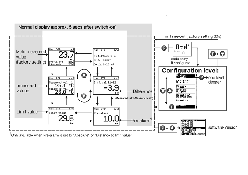
7 Configuration level . . . . . . . . . . . . . . . . . . . . . . . . . . . . . . . . . . . . . . . . . . . . . . . . . . . . . . . . . . 70
7.1 Navigation principle . . . . . . . . . . . . . . . . . . . . . . . . . . . . . . . . . . . . . . . . . . . . . . . . . . . . . . . . . . . . . . . .70
7.2 Analog inputs . . . . . . . . . . . . . . . . . . . . . . . . . . . . . . . . . . . . . . . . . . . . . . . . . . . . . . . . . . . . . . . . . . . . .71
7.2.1 Connection . . . . . . . . . . . . . . . . . . . . . . . . . . . . . . . . . . . . . . . . . . . . . . . . . . . . . . . . . . . . . . . . . . . . . . . . . . . . . . . . . .71
7.2.2 Sensor type 1 . . . . . . . . . . . . . . . . . . . . . . . . . . . . . . . . . . . . . . . . . . . . . . . . . . . . . . . . . . . . . . . . . . . . . . . . . . . . . . . .72
7.2.3 Offset 1 . . . . . . . . . . . . . . . . . . . . . . . . . . . . . . . . . . . . . . . . . . . . . . . . . . . . . . . . . . . . . . . . . . . . . . . . . . . . . . . . . . . . .73
7.2.4 Lead wire resistance 1 . . . . . . . . . . . . . . . . . . . . . . . . . . . . . . . . . . . . . . . . . . . . . . . . . . . . . . . . . . . . . . . . . . . . . . . . .73
7.2.5 Filter time 1 . . . . . . . . . . . . . . . . . . . . . . . . . . . . . . . . . . . . . . . . . . . . . . . . . . . . . . . . . . . . . . . . . . . . . . . . . . . . . . . . . .73
7.2.6 Scaling start 1 . . . . . . . . . . . . . . . . . . . . . . . . . . . . . . . . . . . . . . . . . . . . . . . . . . . . . . . . . . . . . . . . . . . . . . . . . . . . . . . .73
7.2.7 Scaling end 1 . . . . . . . . . . . . . . . . . . . . . . . . . . . . . . . . . . . . . . . . . . . . . . . . . . . . . . . . . . . . . . . . . . . . . . . . . . . . . . . . .73
7.2.8 Sensor type 2 . . . . . . . . . . . . . . . . . . . . . . . . . . . . . . . . . . . . . . . . . . . . . . . . . . . . . . . . . . . . . . . . . . . . . . . . . . . . . . . .74
7.2.9 Offset 2 . . . . . . . . . . . . . . . . . . . . . . . . . . . . . . . . . . . . . . . . . . . . . . . . . . . . . . . . . . . . . . . . . . . . . . . . . . . . . . . . . . . . .75
7.2.10 Lead wire resistance 2 . . . . . . . . . . . . . . . . . . . . . . . . . . . . . . . . . . . . . . . . . . . . . . . . . . . . . . . . . . . . . . . . . . . . . . . . .75
Inhalt

Inhalt
7.2.11 Filter time 2 . . . . . . . . . . . . . . . . . . . . . . . . . . . . . . . . . . . . . . . . . . . . . . . . . . . . . . . . . . . . . . . . . . . . . . . . . . . . . . . . . . 75
7.2.12 Scaling start 2 . . . . . . . . . . . . . . . . . . . . . . . . . . . . . . . . . . . . . . . . . . . . . . . . . . . . . . . . . . . . . . . . . . . . . . . . . . . . . . . .75
7.2.13 Scaling end 2 . . . . . . . . . . . . . . . . . . . . . . . . . . . . . . . . . . . . . . . . . . . . . . . . . . . . . . . . . . . . . . . . . . . . . . . . . . . . . . . . .75
7.3 Limiter/monitor . . . . . . . . . . . . . . . . . . . . . . . . . . . . . . . . . . . . . . . . . . . . . . . . . . . . . . . . . . . . . . . . . . . .76
7.3.1 Device function . . . . . . . . . . . . . . . . . . . . . . . . . . . . . . . . . . . . . . . . . . . . . . . . . . . . . . . . . . . . . . . . . . . . . . . . . . . . . . .76
7.3.2 Switching behavior . . . . . . . . . . . . . . . . . . . . . . . . . . . . . . . . . . . . . . . . . . . . . . . . . . . . . . . . . . . . . . . . . . . . . . . . . . . .77
7.3.3 Limit value, hysteresis . . . . . . . . . . . . . . . . . . . . . . . . . . . . . . . . . . . . . . . . . . . . . . . . . . . . . . . . . . . . . . . . . . . . . . . . . .79
7.3.4 Pre-alarm function . . . . . . . . . . . . . . . . . . . . . . . . . . . . . . . . . . . . . . . . . . . . . . . . . . . . . . . . . . . . . . . . . . . . . . . . . . . . .79
7.3.5 Pre-alarm, hysteresis . . . . . . . . . . . . . . . . . . . . . . . . . . . . . . . . . . . . . . . . . . . . . . . . . . . . . . . . . . . . . . . . . . . . . . . . . . .79
7.3.6 Limit value difference, hysteresis . . . . . . . . . . . . . . . . . . . . . . . . . . . . . . . . . . . . . . . . . . . . . . . . . . . . . . . . . . . . . . . . .80
7.3.7 Setting range min. (formerly ALHI) . . . . . . . . . . . . . . . . . . . . . . . . . . . . . . . . . . . . . . . . . . . . . . . . . . . . . . . . . . . . . . . 80
7.3.8 Setting range max. (formerly ALLO) . . . . . . . . . . . . . . . . . . . . . . . . . . . . . . . . . . . . . . . . . . . . . . . . . . . . . . . . . . . . . .80
7.4 Binary input. . . . . . . . . . . . . . . . . . . . . . . . . . . . . . . . . . . . . . . . . . . . . . . . . . . . . . . . . . . . . . . . . . . . . . .81
7.4.1 Function . . . . . . . . . . . . . . . . . . . . . . . . . . . . . . . . . . . . . . . . . . . . . . . . . . . . . . . . . . . . . . . . . . . . . . . . . . . . . . . . . . . . .81
7.5 Analog output . . . . . . . . . . . . . . . . . . . . . . . . . . . . . . . . . . . . . . . . . . . . . . . . . . . . . . . . . . . . . . . . . . . . .82
7.5.1 Function . . . . . . . . . . . . . . . . . . . . . . . . . . . . . . . . . . . . . . . . . . . . . . . . . . . . . . . . . . . . . . . . . . . . . . . . . . . . . . . . . . . . .82
7.5.2 Signal type . . . . . . . . . . . . . . . . . . . . . . . . . . . . . . . . . . . . . . . . . . . . . . . . . . . . . . . . . . . . . . . . . . . . . . . . . . . . . . . . . . .82
7.5.3 Scaling start . . . . . . . . . . . . . . . . . . . . . . . . . . . . . . . . . . . . . . . . . . . . . . . . . . . . . . . . . . . . . . . . . . . . . . . . . . . . . . . . .82
7.5.4 Scaling end . . . . . . . . . . . . . . . . . . . . . . . . . . . . . . . . . . . . . . . . . . . . . . . . . . . . . . . . . . . . . . . . . . . . . . . . . . . . . . . . . .82
7.5.5 Error signal . . . . . . . . . . . . . . . . . . . . . . . . . . . . . . . . . . . . . . . . . . . . . . . . . . . . . . . . . . . . . . . . . . . . . . . . . . . . . . . . . .83
7.5.6 Behavior when leaving the scaling range . . . . . . . . . . . . . . . . . . . . . . . . . . . . . . . . . . . . . . . . . . . . . . . . . . . . . . . . . . .84
7.6 Display/operation . . . . . . . . . . . . . . . . . . . . . . . . . . . . . . . . . . . . . . . . . . . . . . . . . . . . . . . . . . . . . . . . . .85
7.6.1 Language . . . . . . . . . . . . . . . . . . . . . . . . . . . . . . . . . . . . . . . . . . . . . . . . . . . . . . . . . . . . . . . . . . . . . . . . . . . . . . . . . . . .85
7.6.2 Unit . . . . . . . . . . . . . . . . . . . . . . . . . . . . . . . . . . . . . . . . . . . . . . . . . . . . . . . . . . . . . . . . . . . . . . . . . . . . . . . . . . . . . . . .85
7.6.3 Decimal place . . . . . . . . . . . . . . . . . . . . . . . . . . . . . . . . . . . . . . . . . . . . . . . . . . . . . . . . . . . . . . . . . . . . . . . . . . . . . . . .85

7.6.4 Normal display . . . . . . . . . . . . . . . . . . . . . . . . . . . . . . . . . . . . . . . . . . . . . . . . . . . . . . . . . . . . . . . . . . . . . . . . . . . . . . .85
7.6.5 Contrast . . . . . . . . . . . . . . . . . . . . . . . . . . . . . . . . . . . . . . . . . . . . . . . . . . . . . . . . . . . . . . . . . . . . . . . . . . . . . . . . . . . . .86
7.6.6 Lighting . . . . . . . . . . . . . . . . . . . . . . . . . . . . . . . . . . . . . . . . . . . . . . . . . . . . . . . . . . . . . . . . . . . . . . . . . . . . . . . . . . . . .86
7.6.7 Time-out light . . . . . . . . . . . . . . . . . . . . . . . . . . . . . . . . . . . . . . . . . . . . . . . . . . . . . . . . . . . . . . . . . . . . . . . . . . . . . . . .86
7.6.8 Time-out operation . . . . . . . . . . . . . . . . . . . . . . . . . . . . . . . . . . . . . . . . . . . . . . . . . . . . . . . . . . . . . . . . . . . . . . . . . . . . 86
7.6.9 Code . . . . . . . . . . . . . . . . . . . . . . . . . . . . . . . . . . . . . . . . . . . . . . . . . . . . . . . . . . . . . . . . . . . . . . . . . . . . . . . . . . . . . . .86
7.7 Service . . . . . . . . . . . . . . . . . . . . . . . . . . . . . . . . . . . . . . . . . . . . . . . . . . . . . . . . . . . . . . . . . . . . . . . . . .87
7.7.1 Limit switching cycle . . . . . . . . . . . . . . . . . . . . . . . . . . . . . . . . . . . . . . . . . . . . . . . . . . . . . . . . . . . . . . . . . . . . . . . . . . .87
7.7.2 Current switching cycles . . . . . . . . . . . . . . . . . . . . . . . . . . . . . . . . . . . . . . . . . . . . . . . . . . . . . . . . . . . . . . . . . . . . . . . .87
7.7.3 Operating hours . . . . . . . . . . . . . . . . . . . . . . . . . . . . . . . . . . . . . . . . . . . . . . . . . . . . . . . . . . . . . . . . . . . . . . . . . . . . . . .87
8 Technical data . . . . . . . . . . . . . . . . . . . . . . . . . . . . . . . . . . . . . . . . . . . . . . . . . . . . . . . . . . . . . . 88
8.1 Analog inputs . . . . . . . . . . . . . . . . . . . . . . . . . . . . . . . . . . . . . . . . . . . . . . . . . . . . . . . . . . . . . . . . . . . . .88
8.2 Analog output . . . . . . . . . . . . . . . . . . . . . . . . . . . . . . . . . . . . . . . . . . . . . . . . . . . . . . . . . . . . . . . . . . . . .90
8.3 Binary input. . . . . . . . . . . . . . . . . . . . . . . . . . . . . . . . . . . . . . . . . . . . . . . . . . . . . . . . . . . . . . . . . . . . . . .90
8.4 Relay outputs . . . . . . . . . . . . . . . . . . . . . . . . . . . . . . . . . . . . . . . . . . . . . . . . . . . . . . . . . . . . . . . . . . . . .90
8.5 Measuring circuit monitoring . . . . . . . . . . . . . . . . . . . . . . . . . . . . . . . . . . . . . . . . . . . . . . . . . . . . . . . . .91
8.6 Voltage supply . . . . . . . . . . . . . . . . . . . . . . . . . . . . . . . . . . . . . . . . . . . . . . . . . . . . . . . . . . . . . . . . . . . .91
8.7 Test voltages according to EN 60730, part 1 . . . . . . . . . . . . . . . . . . . . . . . . . . . . . . . . . . . . . . . . . . . . .92
8.8 Electrical safety. . . . . . . . . . . . . . . . . . . . . . . . . . . . . . . . . . . . . . . . . . . . . . . . . . . . . . . . . . . . . . . . . . . .92
8.9 Environmental influences . . . . . . . . . . . . . . . . . . . . . . . . . . . . . . . . . . . . . . . . . . . . . . . . . . . . . . . . . . . .92
8.10 Case . . . . . . . . . . . . . . . . . . . . . . . . . . . . . . . . . . . . . . . . . . . . . . . . . . . . . . . . . . . . . . . . . . . . . . . . . . . .93
8.11 Approvals/approval marks . . . . . . . . . . . . . . . . . . . . . . . . . . . . . . . . . . . . . . . . . . . . . . . . . . . . . . . . . . .94
8.12 Probes for the operating medium air . . . . . . . . . . . . . . . . . . . . . . . . . . . . . . . . . . . . . . . . . . . . . . . . . . .95
8.13 Probes for the operating medium water and oil . . . . . . . . . . . . . . . . . . . . . . . . . . . . . . . . . . . . . . . . . . .96
Inhalt

Inhalt
8.14 Probes for the operating medium water, oil and air . . . . . . . . . . . . . . . . . . . . . . . . . . . . . . . . . . . . . . . .98
9 Setup program . . . . . . . . . . . . . . . . . . . . . . . . . . . . . . . . . . . . . . . . . . . . . . . . . . . . . . . . . . . . . 99
9.1 Minimum hardware and software prerequisites: . . . . . . . . . . . . . . . . . . . . . . . . . . . . . . . . . . . . . . . . . .99
9.2 Displaying the device software version . . . . . . . . . . . . . . . . . . . . . . . . . . . . . . . . . . . . . . . . . . . . . . . . .99
9.3 Forgotten the code? . . . . . . . . . . . . . . . . . . . . . . . . . . . . . . . . . . . . . . . . . . . . . . . . . . . . . . . . . . . . . . .100
9.4 Special function: thermocouple reverse polarity protection. . . . . . . . . . . . . . . . . . . . . . . . . . . . . . . . .100
10 Alarm messages . . . . . . . . . . . . . . . . . . . . . . . . . . . . . . . . . . . . . . . . . . . . . . . . . . . . . . . . . . . 101
11 Error messages . . . . . . . . . . . . . . . . . . . . . . . . . . . . . . . . . . . . . . . . . . . . . . . . . . . . . . . . . . . . 102
12 What to do, if … . . . . . . . . . . . . . . . . . . . . . . . . . . . . . . . . . . . . . . . . . . . . . . . . . . . . . . . . . . . . 107
13 Information for devices with extra code 062 GL . . . . . . . . . . . . . . . . . . . . . . . . . . . . . . . . . 109
13.1 Technical data . . . . . . . . . . . . . . . . . . . . . . . . . . . . . . . . . . . . . . . . . . . . . . . . . . . . . . . . . . . . . . . . . . .109
13.2 Alarm messages . . . . . . . . . . . . . . . . . . . . . . . . . . . . . . . . . . . . . . . . . . . . . . . . . . . . . . . . . . . . . . . . . .109
13.3 Locks . . . . . . . . . . . . . . . . . . . . . . . . . . . . . . . . . . . . . . . . . . . . . . . . . . . . . . . . . . . . . . . . . . . . . . . . . .109
14 Output behavior . . . . . . . . . . . . . . . . . . . . . . . . . . . . . . . . . . . . . . . . . . . . . . . . . . . . . . . . . . . 111


2014-05-01
1 Brief description
10
1 Brief description
The safety temperature limiter (STB) and the safety temperature monitor (STW) are used to reliably detect and avert hazards
that could cause injuries, are harmful to the environment or cause destruction of production plants and produced goods, at an
early stage.
Its primary task is to reliably monitor thermal processes and switch the systems to an operationally safe status in the event of
malfunctions.
The measured value at the analog input can be recorded by various probes or standard signals.
The limit value overrange is indicated by the installed LEDs K1 and K2 (red) for each channel, and the installed relay «Alarm»
switches the system to an operationally safe status (alarm range).
The high standards of DIN EN 61508 and DIN EN ISO 13849 are met by a device design, the 1oo2D structure of which ensures
reliable detection of errors and, thus, can also be used for applications according to the new Machinery Directive 2006/42/EC.
1.1 Safety temperature monitor (STW)
The STW is a safety component according to Machinery Directive, which, when activated, resets automatically if the probe
temperature has gone below / exceeded the limit value by an amount equal to the hysteresis. Possible settings: monitoring for
limit value overrange or underrange.
v Chapter 7.3.2 «Switching behavior»
1.2 Safety temperature limiter (STB)
The STB is a safety component according to Machinery Directive that is permanently locked after response. Manual reset using
the key is only possible once the probe temperature has gone below / exceeded the limit value by an amount equal to the
hysteresis. Possible settings: monitoring for limit value overrange or underrange.
v Chapter 7.3.2 «Switching behavior»
The transparent cover can be lead sealed to prevent unauthorized operation.
However, the key remains accessible.
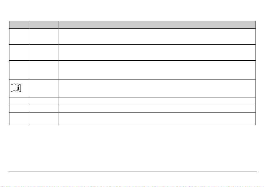
1.3 Safety information
Symbol Meaning Explanation
Note This symbol is used to draw your attention to important information.
Caution This symbol is used when there is a risk of damage to equipment or data if the instructions are ig-
Danger This symbol is used when there is a risk of injury to persons if the instructions are ignored or not
Read This text contains important information and must always be read before work is continued. Han-
v Reference This symbol refers to further information in other manuals, chapters or sections.
1
abc
*
2014-05-01
Footnote Footnotes are remarks referring to specific points in the text marked with a superscript number.
Instructions
for action
nored or not followed correctly.
followed correctly.
dling the device in any way that is not described in the Operating Manual or that is expressly forbidden will jeopardize your warranty rights.
This symbol indicates that an action to be performed is described. The individual steps are marked
by an asterisk.
1 Brief description
11
2014-05-01
Voltage supply AC 110 to 240 V:
Voltage supply AC/DC20 to 30 V:
Switching behavior
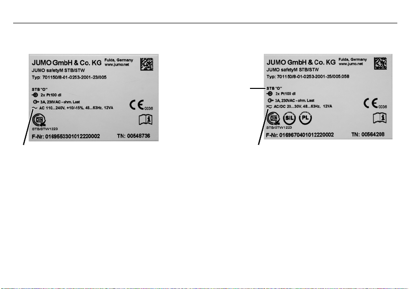
2 Identifying the device version
The type plate is affixed to the side of the device.
The voltage supply must correspond to the voltage given on the type plate!
2 Identifying the device version
12

Basic type
701150 Safety temperature limiters (STB) / monitors (STW) according to DIN EN 14597
Ver sion
8 Factory setting
9 Configured according to customer specifications
01 German (factory setting)
02 English
03 French
0251 Safety temperature monitor max. alarm (inverse, N/C contact)
0252 Safety temperature monitor min. alarm (direct, N/O contact)
0253 Safety temperature limiter max. alarm (inverse, N/C contact)
0254 Safety temperature limiter min. alarm (direct, N/O contact)
1003 1x Pt100 in 2-wire circuit
2001 2x Pt100 in 3-wire circuit (ex-factory)
2003 2x Pt100 in 2-wire circuit
2006 2x Pt1000 in 3-wire circuit
2037 2x W3Re-W25Re «D»
2039 2x Cu-CuNi «T»
2040 2x Fe-CuNi «J»
2041 2x Cu-CuNi «U»
2042 2x Fe-CuNi «L»
2043 2x NiCr-Ni «K»
Language
Switching behavior
Measuring input1 (programmable)
2014-05-01
2 Identifying the device version
13

2014-05-01
2044 2x Pt10Rh-Pt «S»
2045 2x Pt13Rh-Pt «R»
2046 2x Pt30Rh-Pt6Rh «B»
2048 2x NiCrSi-NiSi «N»
1053 1x 4 to 20 mA
2053 2x 4 to 20 mA
23 AC 110 to 240 V +10 % /-15 %, 48 to 63 Hz
25 20 to 30 V AC/DC, 48 to 63 Hz
701150 / 8 — 01 — 0253 — 2001 — 23 / 005 , 062
1. The first number on the measuring input means single probe «1“ or double probe «2“
2 Identifying the device version
Voltage supply
Analog output (configurable)
001 0 to 20 mA
005 4 to 20 mA (ex-factory)
040 0 to 10 V
070 2 to 10 V
Extra code
2.1 Scope of delivery
-JUMO safetyM STB/STW in the version ordered
— Operating Manual B701150.0
058 SIL and PL approval
062 GL approval
14
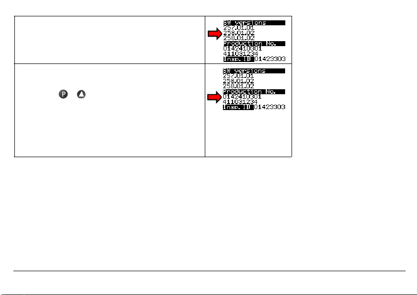
2.2 Device software versions
Diagnosis module version: 257.01.01
Analog channel 1 version: 258.01.02
Analog channel 2 version: 258.01.02
2.3 Serial number
The serial number is indicated on the device.
h Press the + keys
Construction:
The first 8 digits specify the serial number: 01424103
Digit 9 and 10 the production plant in Fulda: 01
Digit 11 (second line) the hardware version: 4
Digit 12 and 13 the year: 2011
Digit 14 and 15 the calendar week: 03
Digit 16 to 19 consecutive numbers: 1234
2.4 Service addresses
Phone support in Germany:
Telephone:+49 661 6003-9135
Fax: +49 661 6003-881899
Email: service@jumo.net
2014-05-01
Austria:
Telephone:+43 1 610610
Fax: +43 1 6106140
Email: info@jumo.at
Switzerland:
Telephone:+41 44 928 24 44
Fax: +41 44 928 24 48
Email: info@jumo.ch
2 Identifying the device version
15
2014-05-01
2 Identifying the device version
This operating manual is a translation of the German original manual.
It is valid for the following hardware and software versions:
Diagnosis module from version: 257.01.01
Analog channel 1 from version: 258.01.02
Analog channel 2 from version: 258.01.02
Hardware version: 0
16
h Press the + keys
Keep the operating manual in a place accessible to all users at all times.
All necessary settings are described in this Operating Manual.
Handling the device in any way that is not described in the Operating Manual or that is expressly forbidden will
jeopardize your warranty rights and may disable the safety function.
It is forbidden to access the inside of the device!
Repairs may only be performed by JUMO at the head office in Fulda.
Please contact the nearest subsidiary or the head office should you encounter any problems.
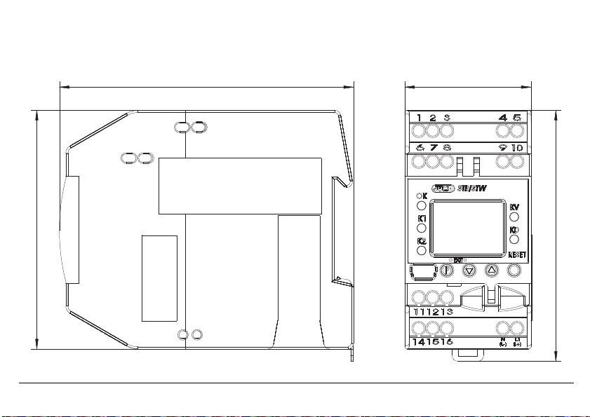
3 Installation
3.1 Dimensions
2014-05-01
3 Installation
17
2014-05-01
3.2 Installation location, DIN rail installation
The device is not suitable for use in potentially explosive atmospheres.
The device is hooked into a 35 mm DIN rail (EN 60715) from the front and
pushed down to engage.
The ambient conditions at the installation site must meet the requirements
v
specified in the technical data.
Chapter 8 «Technical data»
As far as possible, the installation site should be vibration-free to prevent the screw-connections from working loose.
a
The installation site should be free from aggressive media, e.g. acids and lyes, and, if possible, free from dust, flour or
a
other suspended matter in order to prevent the cooling slots from becoming clogged.
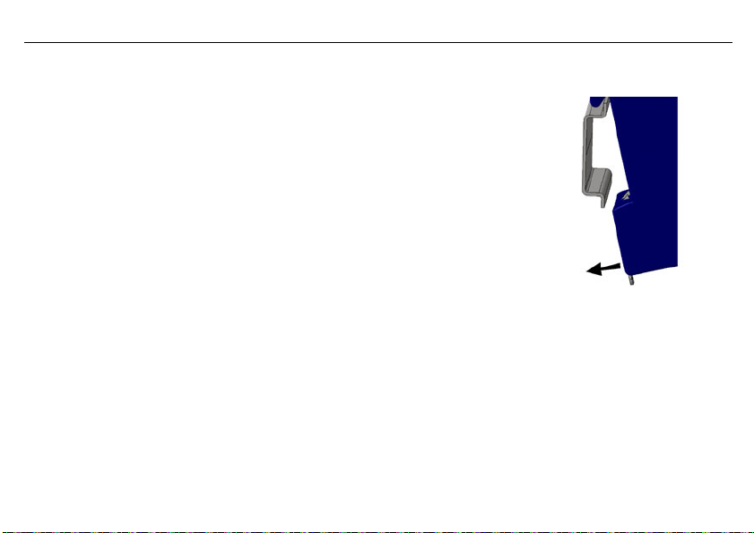
3.3 Close mounting
Observe a minimum spacing of 20 mm from the top and bottom.
a
1. To allow the release slot to be accessed with a screwdriver from below.
2. To allow the device to be swiveled up and unhooked from the DIN rail for removal.
Several devices may be mounted side by side without a gap.
a
3 Installation
18
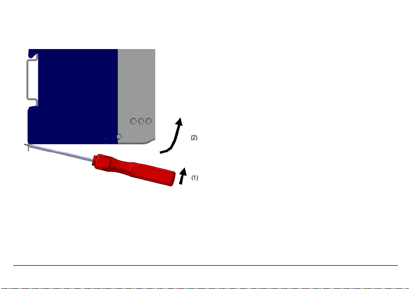
3.4 Dismantling
h Insert a screwdriver into the release lug from below and lift up (1).
h Simultaneously swivel the screwdriver and case up out of the DIN rail (2).
2014-05-01
3 Installation
19
2014-05-01
»
3700 V AC
»
3700 V AC
(1)
(2)
(4)
(3)
(5)
(8)
(6)
(7)
»
3700 V AC
50 V DC
»
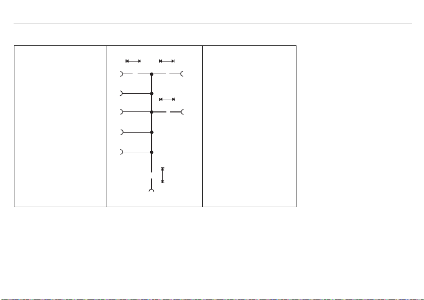
3.5 Electrical isolation
3 Installation
20
(1) Analog inputs
(3) Binary input
(5) Setup interface
(6) Display
(7) Analog output
3.6 Use of the setup interface
— The setup interface USB is only designed for service use for a limited period, e.g. for transmitting setup data and during
— It is not suitable for operation in a fixed installation for an unlimited period as the monitoring function is switched off during
(8) Power supply
commissioning.
data transmission with the setup program.
(2) Relay output «Alarm»
(4) Relay output «Pre-alarm»

4 Electrical connection
4.1 Installation notes
Check that the safety temperature limiter is correctly installed for its application (temperature measurement) and is oper-
a
ated within the admissible system parameters.
The device is designed for installation in switch cabinets, machines/plants or systems.
a
Ensure that the customer’s fuse rating does not exceed 20 A.
Isolate the device at all poles prior to starting service or repair work.
a
All incoming and outgoing lines without a connection to the power supply network must be laid with shielded and
a
twisted lines. Connect the screen on the device side to ground.
Do not run input and output lines close to current-carrying components or cables.
a
Do not connect any additional consumers to the screw terminals for the device power supply.
a
The choice of cable, the installation and the electrical connection of the device must conform to the requirements of VDE
a
0100 «Regulations on the Installation of Power Circuits with Nominal Voltages below 1000 V» or the appropriate local
regulations.
Protect the relay circuit by suitable measures.
a
The maximum contact rating is 230 V/3 A (ohmic load).
The electromagnetic compatibility conforms to the standards and regulations cited in the technical data.
a
v Chapter 8 «Technical data»
During commissioning we recommend carrying out a trial run of the system until temperature switch-off at the set limit.
a
Only allow qualified electricians to carry out the electrical connection and the configuration settings until commissioning.
2014-05-01
4 Electrical connection
21

2014-05-01
4 Electrical connection
The approval according to DIN EN 14597 is only valid when the correct probe with DIN approval is set in the configuration level and also connected.
The limit value to be monitored must be within the admissible temperature range of the DIN probe.
v Chapter 8.12 «Probes for the operating medium air»
v Chapter 8.13 «Probes for the operating medium water and oil»
The monitoring function is deactivated during data transmission using the setup program.
v Chapter 12 «What to do, if …»
22
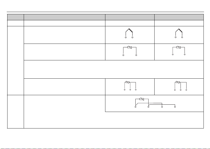
4.2 Connection diagram
Connection is carried out via screw terminals. Lead Admissible cross sec-
1 wire
fine-strand,
with core-end ferrule
2014-05-01
4 Electrical connection
tion
≤ 2.5 mm
≤ 1.5 mm
2
2
23
2014-05-01
A
Enter the lead resistance for RTD temperature probes in two-wire circuit when using greater line
lengths.
v Setup program: edit => analog inputs
4 Electrical connection
Legend Remark Screw terminals Screw terminals
1, 2 Analog input1 (E1) Analog input2 (E2)
Thermocouple/
double thermocouple
RTD temperature probe Pt100/Pt1000 in
2-wire circuit
RTD temperature probe Pt100/Pt1000
in three-wire circuit
RTD temperature probe Pt100 in
two-wire circuit, individual probe for both analog
inputs
Caution:
When only one probe (SIL2) is connected, the temperature limitation device
is reduced from SIL3 to SIL2. However, the internal 2-channel structure (1oo2D) in the device is still retained.
Both channels measure the same probe due to the simplified external circuit.
24
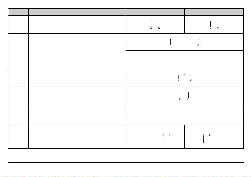
Legend Remark Screw terminals Screw terminals
4 to 20 mA
4 to 20 mA for both analog inputs
Caution:
When only one probe (SIL2) is connected, the temperature limitation device
is reduced from SIL3 to SIL2. However, the internal 2-channel structure (1oo2D) in the device is still retained.
Both channels measure the same current signal due to the simplified external circuit.
4 Binary input
Connection to a potential-free contact
5 Analog output:
0 to 20 mA
4 to 20 mA (ex-factory)
0(2) to 10V
Caution
The analog output is not part of the safety func-
tion!
9 Voltage supply
2014-05-01
according to rating plate
AC:
L1 Line conductor
N Neutral
4 Electrical connection
DC:
(L+)
(L-)
25
2014-05-01
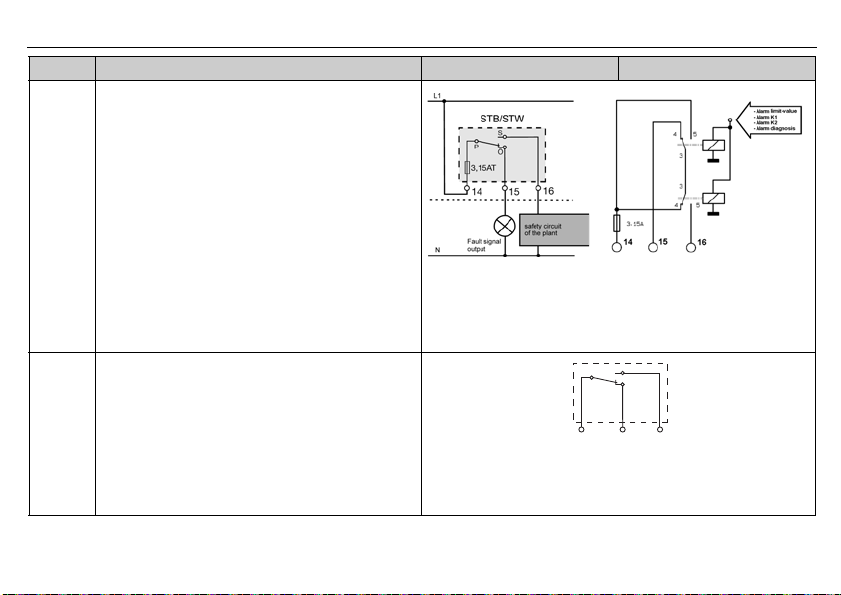
Legend Remark Screw terminals Screw terminals
10 Relay output «Alarm» (current-free state)
Relay (changeover contact element) with fuse cutout
4 Electrical connection
26
11 Relay output for pre-alarm (KV)
Changeover contact
Caution
The pre-alarm relay output is not part of the
safety function!
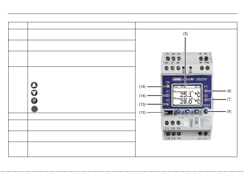
5 Commissioning the device
(1) (2) (3)
(4)
(5)
(6)
(7)
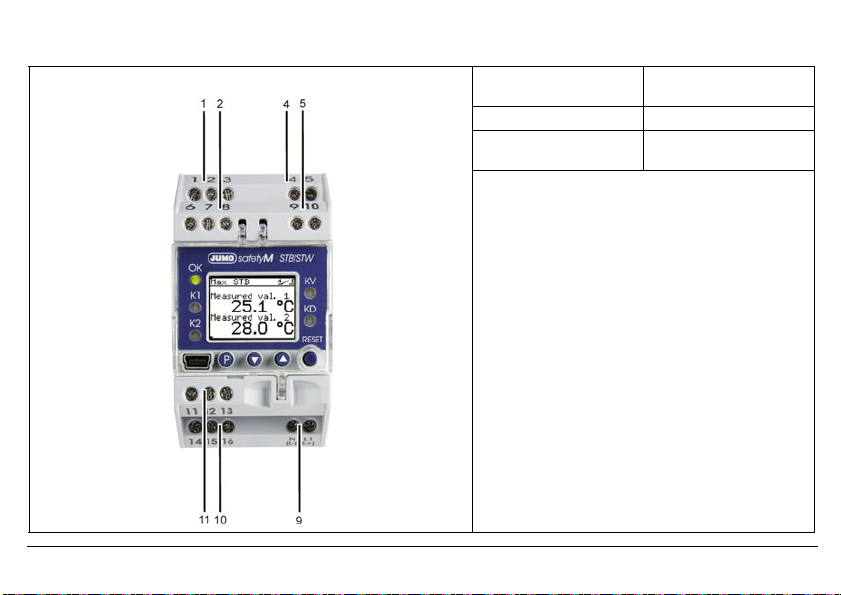
5.1 Display and operating elements
h Connect the voltage supply — a test routine will start during which all LEDS will flash and the display with background light-
ing will indicate white pixels for 2 seconds and black pixels for 2 seconds.
Once the test routine has been completed, the device will indicate the main measured value (factory set).
v If an alarm or error message appears, refer to Chapter 10 «Alarm messages».
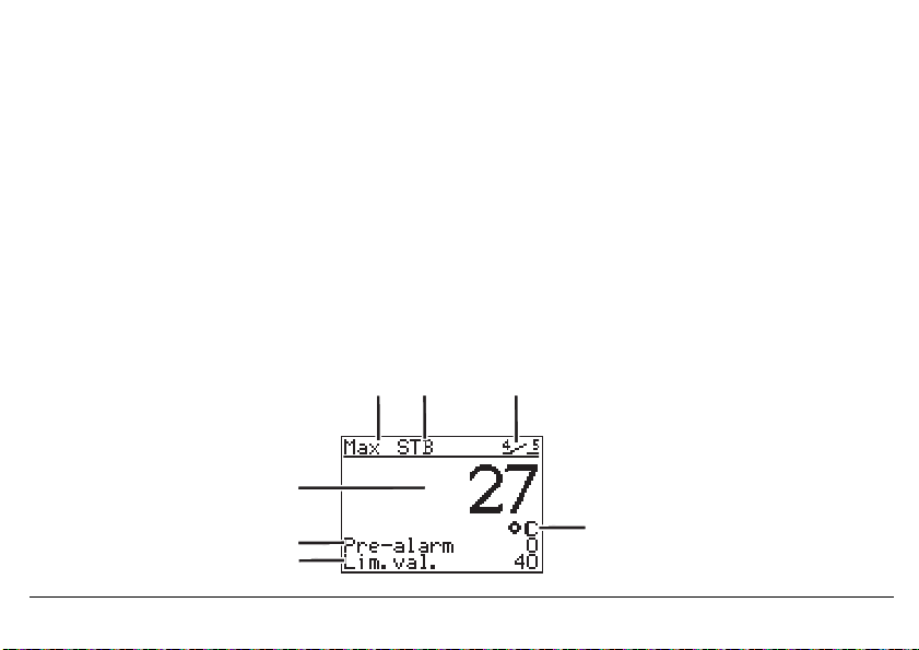
5.2 Setting the display after switch-on
v Chapter 7.6.4 «Normal display»
The screen is factory set to show the main measured value in German. The example shows the screen layout of a safety temperature limiter monitoring a maximum value of 29.6°C with a pre-alarm set to 9.9°C.
If the main measured value is within the hysteresis during «Power ON», the relay outputs «Pre-alarm» and «Alarm»
are deactivated.
1 Switching behavior 2 Device function
3 Binary input
7 Main measured value
6 Pre-alarm 4 Temperature unit
5 Limit value
2014-05-01
5 Commissioning the device
27
2014-05-01
Legend Remark
3LCD display
6 LED KV (yellow)
7 LED KD (yellow)
8Keys
12 Setup interface
13 LED K2 (red)
14 LED K1 (red)
15 LED OK
Black and white with background lighting 96 x 64 pixels
Is lit if the pre-alarm was triggered.
Is lit if the diagnosis processor has switched off a component.
(Can only be operated when the transparent hood is folded up)
Increase value / previous parameter
Reduce value / next parameter
Programming
RESET
Is lit for all errors.
Is lit for all errors.
Green: OK range
OFF: Error occurred
5 Commissioning the device
28
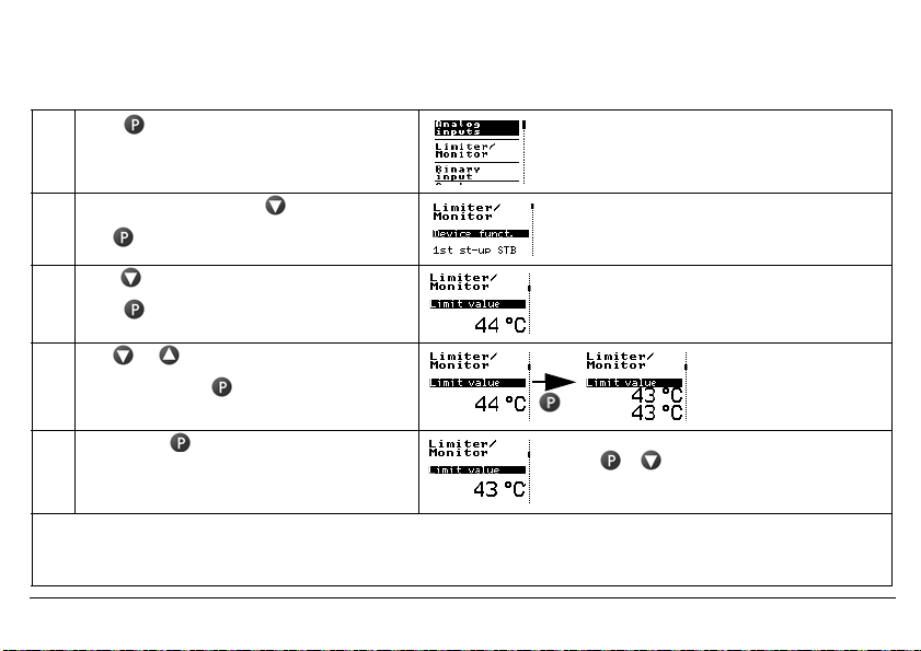
5.3 Selecting and editing parameters (plausibility inquiry for input values)
The values are displayed in the standard display.
Carry out steps 1 to 4 to edit a value, e.g. in this case, the limit value
1 Press The first menu item «Analog inputs» has a black
2 Select limiter/monitor with
Use to change to the submenu
3 Press 2x until the limit value appears
Press (limit value flashes)
background. The vertical line on the right shows
the current position.
4 Use or to set the desired value
Acknowledge with
(limit value is shown in duplicate)
5 Briefly press to confirm the value.
The value is applied and saved.
If no key is pressed, the device automatically returns to the standard display after 30 seconds (timeout) and the value
H
is not saved. The length of the timeout is configurable.
Use + to return to the standard display
or menu topic «Back» or
return automatically after a timeout
Limit value flashes in duplicate on the display as a
control.
v see operating overview on the first inner page of this manual.
2014-05-01
5 Commissioning the device
29
2014-05-01
5 Commissioning the device
30
5.4 Aborting edit
+ are used to abort editing and retain the previous value.
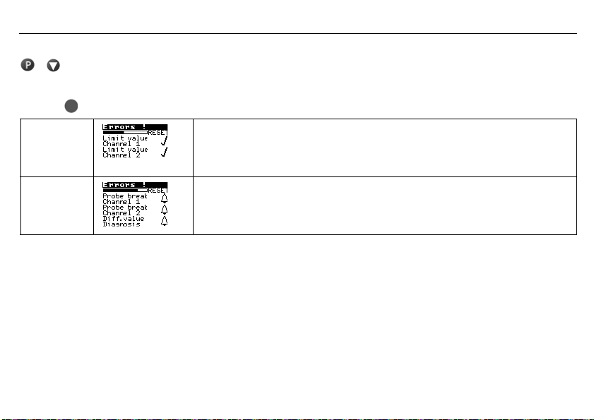
5.5 Alarm acknowledgement using the Reset key (only for temperature limiters STB)
h Press key and hold down
Ticks appear
after the errors
A bell is
shown after
the error.
The alarm is no longer pending and is acknowledged as soon as the time bar has finished (3 seconds).
The alarm condition is still pending and cannot be acknowledged.
5.6 Alarm acknowledgement via binary input (only for temperature limiters STB)
The binary input can be configured so that, for example, alarms can be unlocked via a potential-free contact.
The function only reacts to the switching flank from the «open» to the «closed» state.
The contact then behaves in the same way as the «Reset» button.
v Chapter 7.4.1 «Function»
Loading…