
Обкатка нового автомобиля
Для обкатки автомобиля данной модели не существует каких-либо специальных правил, однако, следует избегать высокой скорости первые 1500 км. Рекомендуется чаше переходить…
Лицевая панель
В различных моделях Ford внешний вид панели и расположение на ней приборов и органов управления могут иметь некоторые расхождения.
Панель приборов
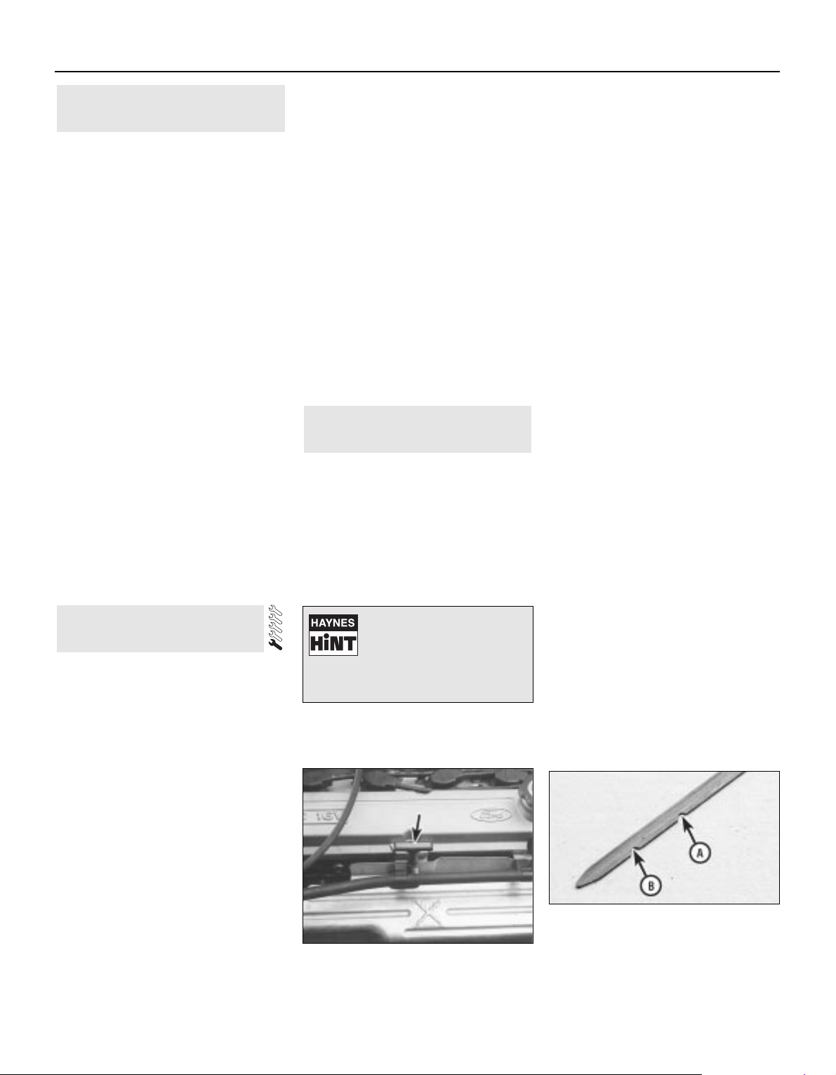
На рисунке изображены два возможных варианта приборной панели автомобиля Ford Mondeo. Комментарии к каждому пункту приведены ниже. 1. Контрольная лампа указателей…
Графический дисплей
Смотрите позицию 17 в Параграфе 2 . Графический дисплей работает при включенном зажигании. Он контролирует состояние стоп-сигналов, габаритных огней, фар ближнего света…
Часы и бортовой компьютер
Цифровые часы Смотрите позицию 18 в Параграфе 2 . Часы отображают время при включенном зажигании. Они могут работать в 12- или 24-часовом режиме, а также отображать…
Система отопления и вентиляции
Смотрите позицию 21 в Параграфе 2 . Система отопления и вентиляции устроена следующим образом. Наружный воздух поступает в воздухозаборник, находящийся у лобового…
Управление кондиционером
Смотрите позицию 21 в Параграфе 2 . Кондиционер работает только при включенном двигателе и температуре выше +4°C. Рукоятка переключателя режимов имеет семь положений….
Прикуриватель, пепельница и вещевой ящик
Прикуриватель Предупреждение: Никогда не держите прикуриватель нажатым, поскольку это грозит пожаром. Если в машине остаются дети, его следует убирать. Чтобы…
Регулирование света в салоне. Верхний люк
Освещение салона Переключатель ламп освещения салона имеет три положения: 1 — контакт с дверями; 2 — выключено; 3 — включено. Лампы освещения салона и его подсветки…
Предупредительная парковочная система
Предупредительная парковочная система (ППС) состоит из двух ультразвуковых датчиков, установленных на заднем бампере, регулятора и дисплея в зоне видимости заднего…
Органы управления на дверях
Ручное регулирование наружных зеркал Отрегулировать наружные зеркала вручную можно изнутри салона. Окна с электроприводом Предупреждение: Когда в машине остаются дети,…
Оборудование на консоли
Пятиступенчатая коробка передач с ручным переключением Заднюю передачу можно включить только тогда, когда автомобиль неподвижен. Чтобы включить заднюю передачу,…
Багажное отделение
Полка багажника (Хэтчбэк) Снятие Снимите два фиксирующих ремня, расположенных на задней двери. Затем отстегните полку вдоль по бокам и вытяните ее горизонтально, не…
Ключи и замки
Ключи Такой ключ запирает и открывает все замки автомобиля. Обычно каждый ключ имеет свой номер, а комплект ключей сопровождается специальной биркой. В случае потери…
Охранная сигнализация
Охранная сигнализация защищает двери, капот и багажник от несанкционированного открывания. Обычная охранная сигнализация Включение Система включается при закрывании…
Есть 1 комментарий
Регулировка сидений
Установка сиденья Сиденья, подголовники, ремни и подушки безопасности составляют единую систему. Оптимальное соотношение ее компонентов и их правильная эксплуатация…
Ремни безопасности
Ремни безопасности — обязательная принадлежность автомобиля, которая позволяет во многих случаях избежать травм и повреждений, ими следует пользоваться всегда. Каждый…
Подушка безопасности
Общие сведения Подушка является дополнительным средством безопасности и предохраняет водителя в серьезной аварийной ситуации. Подушка приводится в действие при любом…
Особенности запуска двигателя
Включение зажигания Для включения нужно повернуть ключ зажигания по часовой стрелке. Стартер не следует держать включенным более 5 секунд (20 секунд на моделях с…
Система управления тяговой силой
Смотрите позицию 24 в Параграфе 2 . Принцип действия Система управления тяговой силой предотвращает пробуксовку ведущих колес при плохом сцеплении с дорогой. Когда одно…
Саморегулируемая задняя подвеска
Если установлена саморегулируемая задняя подвеска, автомобиль, независимо от нагрузки, при движении будет сохранять дорожный просвет (клиренс). Если автомобиль оснащен…
Багажник на крыше
Максимальная нагрузка багажника на крыше — 75 кг, на модели Универсал со встроенным багажником — 100 кг. Предупреждение: При нагруженном багажнике центр тяжести…
Режим ограниченной управляемости
Система управления бензиновыми двигателями оснащена программой «ограниченной управляемости», которая работает следующим образом. Если в процессе движения система…
Заполнение топливной системы
Поспе выполнения ремонтных работ в топливной системе ее трубопроводы оказываются пустыми, и это вызовет трудности при запуске двигателя. Поэтому топливную систему надо…
Прерыватель подачи топлива
Автомобили Ford-Mondeo оснащены прерывателем подачи топлива в случае аварии, например, столкновения, переворота. В таких случаях срабатывает автоматический выключатель и…
Принудительное выключение режима парковки
В случае разряда аккумулятора могут возникнуть трудности с выводом рычага селектора из положения парковки «Р». Чтобы вывести рычаг селектора из положения «Р», вставьте…
Новости компании Форд

Ребят всем привет, выкладываю найденную инструкцию к данным автомобилям, читал сам, многое нашел что меня интересовало.
Полный разбор авто, разбор механики и автомата, двигателей 4 цилиндровых и 6, разные комплектации, полные Электро схемы автомобиля, настройка всех функций и доп приборов, в общем для новичков и ветеранов данной марки автомобиля)))))
Она подходит для ФМ1, ФМ2
Выкладываю на файлообменник внешний, если вдруг ссылка не работает сообщите, перезалью.
Файлообменник с ФМ

Ford Mondeo
Service and Repair Manual
Jeremy Churchill and A K Legg LAE MIMI
Models covered
All Ford Mondeo models with four-cylinder petrol engines,
including special/limited editions
1597 cc, 1796 cc and 1988 cc
Does not cover Diesel or V6 engines, or four-wheel-drive models
© Haynes Publishing 1996
A book in the Haynes Service and Repair Manual Series
All rights reserved. No part of this book may be reproduced or transmitted
in any form or by any means, electronic or mechanical, including
photocopying, recording or by any information storage or retrieval system,
without permission in writing from the copyright holder.
ISBN 1 85960 167 7
British Library Cataloguing in Publication Data
A catalogue record for this book is available from the British Library.
Printed by J H Haynes & Co. Ltd, Sparkford, Nr Yeovil,
Somerset BA22 7JJ
Haynes Publishing
Sparkford, Nr Yeovil, Somerset BA22 7JJ, England
Haynes North America, Inc
861 Lawrence Drive, Newbury Park, California 91320, USA
Editions Haynes S.A.
147/149, rue Saint Honoré, 75001 PARIS, France
(1923-304-10X3)

LIVING WITH YOUR FORD MONDEO
Introduction Page 0•4
Safety First! Page 0•5
General dimensions and weights Page 0•6
MOT Test Checks
Checks carried out from the driver’s seat Page 0•7
Checks carried out with the vehicle on the ground Page 0•8
Checks carried out with the vehicle raised Page 0•9
Checks carried out on your vehicle’s exhaust emission system Page 0•10
Roadside Repairs
Jacking, towing and wheel changing Page 0•11
Booster battery (jump) starting Page 0•12
Identifying leaks Page 0•13
Conversion factors Page 0•14
Routine Maintenance
Routine maintenance and servicing Page 1•1
Lubricants, fluids and capacities Page 1•2
Maintenance schedule Page 1•3
Weekly checks Page 1•6
Every 10 000 miles or 12 months Page 1•11
Every 20 000 miles or 2 years Page 1•20
Every 30 000 miles or 3 years Page 1•22
Every 60 000 miles Page 1•26
Every 3 years Page 1•26
Contents

REPAIRS & OVERHAUL
Engine and Associated Systems
In-car engine repair procedures Page 2A•1
Engine removal and general engine overhaul procedures Page 2B•1
Cooling, heating and air conditioning systems Page 3•1
Fuel and exhaust systems Page 4•1
Engine electrical systems Page 5•1
Emissions control systems Page 6•1
Transmission
Manual transmission Page 7A•1
Automatic transmission Page 7B•1
Clutch and driveshafts Page 8•1
Brakes
Braking system Page 9•1
Suspension
Suspension and steering systems Page 10•1
Body Equipment
Bodywork and fittings Page 11•1
Electrical
Body electrical systems Page 12•1
Wiring Diagrams Page 12•24
REFERENCE
Tools and Working Facilities Page REF• 1
General Repair Procedures Page REF• 4
Buying spare parts and vehicle identification numbers Page REF• 5
Fault Finding Page REF• 6
Glossary of Technical Terms Page REF•13
Index Page REF•17
Contents
0•4
Introduction
Introduced in March 1993, the Ford
Mondeo models are available in four-door
Saloon, five-door Hatchback and five-door
Estate configurations. All feature a high
standard of equipment, with driver/passenger
safety in accidents being a particularly high
design priority; all models are fitted with
features such as side impact bars in all doors,
“anti-submarine” seats combined with “seat
belt grabbers” and pre-tensioners, and an
airbag fitted to the steering wheel. Vehicle
security is enhanced, with an in-built alarm
system and engine immobiliser being fitted as
standard, as well as double-locking doors
with shielded locks, and security-coded audio
equipment.
The four-cylinder petrol engine is a new
design, available in 1.6, 1.8 and 2.0 litre
capacities. It is controlled by a sophisticated
engine management system, which combines
multi-point sequential fuel injection and
distributorless ignition systems with
evaporative emissions control, exhaust gas
recirculation and a three-way regulated
catalytic converter (with a pulse-air system for
rapid warm-up) to ensure that the vehicle
complies with the most stringent of the
emissions control standards currently in force,
and yet provides the levels of performance
and fuel economy expected.
The transversely-mounted engine drives
the front roadwheels through either a fivespeed manual transmission with a cableoperated clutch, or through an electronicallycontrolled four-speed automatic transmission.
The fully-independent suspension is by
MacPherson strut on all four roadwheels,
located by transverse lower arms at the front,
and by transverse and trailing arms at the rear;
anti-roll bars are fitted at front and rear. The
Estate rear suspension is of a different design,
to give maximum loadspace inside the
vehicle, with self-levelling suspension units
available as an option. On some models, the
suspension is electronically-controlled
through the Adaptive Damping System.
The steering is power-assisted, the pump
being belt-driven from the engine, and the
rack-and-pinion steering gear mounted
behind the engine.
The vacuum servo-assisted brakes are disc
at the front, with drums at the rear on most
models; disc rear brakes and an
electronically-controlled Anti-lock Braking
System (ABS) are available on some models,
with a T raction Contr ol System (TCS) available
as a further option where ABS is fitted.
Acknowledgements
Thanks are due to Champion Spark Plug,
who supplied the illustrations showing spark
plug conditions. Certain other illustrations are
the copyright of the Ford Motor Company,
and are used with their permission. Thanks
are also due to Sykes-Pickavant Limited, who
provided some of the workshop tools, and to
all those people at Sparkford who helped in
the production of this manual.
Project vehicles
The main project vehicle used in the
preparation of this manual, and appearing in
many of the photographic sequences, was a
1993-model Ford Mondeo 2.0 Si Hatchback.
Additional work was carried out and
photographed on a 1993-model 2.0 Si Saloon
and a 1993-model 2.0 Ghia Estate (with
automatic transmission).
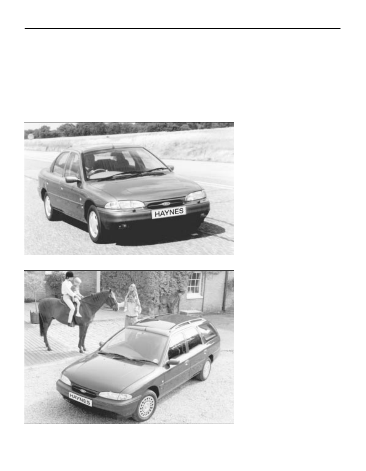
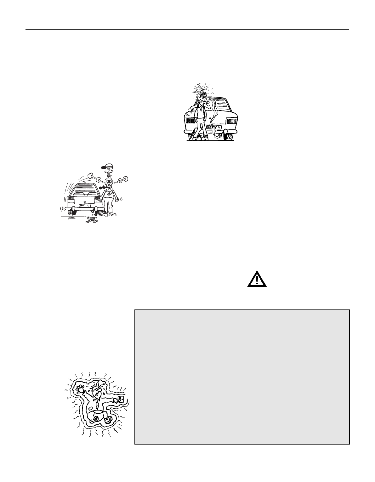
Introduction to the Ford Mondeo
Ford Mondeo 2.0 Ghia Saloon
Ford Mondeo 1.8 GLX Estate
Working on your car can be dangerous.
This page shows just some of the potential
risks and hazards, with the aim of creating a
safety-conscious attitude.
General hazards
Scalding
• Don’t remove the radiator or expansion
tank cap while the engine is hot.
• Engine oil, automatic transmission fluid or
power steering fluid may also be dangerously
hot if the engine has recently been running.
Burning
• Beware of burns from the exhaust system
and from any part of the engine. Brake discs
and drums can also be extremely hot
immediately after use.
Crushing
• When working under or near
a raised vehicle, always
supplement the
jack with axle
stands, or use
drive-on ramps.
Never venture
under a car
which is only
supported by
a jack.
• Take care if loosening or tightening hightorque nuts when the vehicle is on stands.
Initial loosening and final tightening should
be done with the wheels on the ground.
Fire
• Fuel is highly flammable; fuel vapour is
explosive.
• Don’t let fuel spill onto a hot engine.
• Do not smoke or allow naked lights
(including pilot lights) anywhere near a
vehicle being worked on. Also beware of
creating sparks
(electrically or by use of tools).
• Fuel vapour is heavier than air, so don’t
work on the fuel system with the vehicle over
an inspection pit.
• Another cause of fire is an electrical
overload or short-circuit. Take care when
repairing or modifying the vehicle wiring.
• Keep a fire extinguisher handy, of a type
suitable for use on fuel and electrical fires.
Electric shock
• Ignition HT
voltage can be
dangerous,
especially to
people with
heart problems
or a pacemaker.
Don’t work on or
near the ignition
system with the
engine running or the
ignition switched on.
• Mains voltage is also dangerous. Make
sure that any mains-operated equipment is
correctly earthed. Mains power points should
be protected by a residual current device
(RCD) circuit breaker.
Fume or gas intoxication
• Exhaust fumes are
poisonous; they often
contain carbon
monoxide, which is
rapidly fatal if inhaled.
Never run the
engine in a
confined space
such as a garage
with the doors shut.
• Fuel vapour is also
poisonous, as are the vapours from some
cleaning solvents and paint thinners.
Poisonous or irritant substances
• Avoid skin contact with battery acid and
with any fuel, fluid or lubricant, especially
antifreeze, brake hydraulic fluid and Diesel
fuel. Don’t syphon them by mouth. If such a
substance is swallowed or gets into the eyes,
seek medical advice.
• Prolonged contact with used engine oil can
cause skin cancer. Wear gloves or use a
barrier cream if necessary. Change out of oilsoaked clothes and do not keep oily rags in
your pocket.
• Air conditioning refrigerant forms a
poisonous gas if exposed to a naked flame
(including a cigarette). It can also cause skin
burns on contact.
Asbestos
• Asbestos dust can cause cancer if inhaled
or swallowed. Asbestos may be found in
gaskets and in brake and clutch linings.
When dealing with such components it is
safest to assume that they contain asbestos.
Special hazards
Hydrofluoric acid
• This extremely corrosive acid is formed
when certain types of synthetic rubber, found
in some O-rings, oil seals, fuel hoses etc, are
exposed to temperatures above 4000C. The
rubber changes into a charred or sticky
substance containing the acid. Once formed,
the acid remains dangerous for years. If it
gets onto the skin, it may be necessary to
amputate the limb concerned.
• When dealing with a vehicle which has
suffered a fire, or with components salvaged
from such a vehicle, wear protective gloves
and discard them after use.
The battery
• Batteries contain sulphuric acid, which
attacks clothing, eyes and skin. Take care
when topping-up or carrying the battery.
• The hydrogen gas given off by the battery
is highly explosive. Never cause a spark or
allow a naked light nearby. Be careful when
connecting and disconnecting battery
chargers or jump leads.
Air bags
• Air bags can cause injury if they go off
accidentally. Take care when removing the
steering wheel and/or facia. Special storage
instructions may apply.
Diesel injection equipment
• Diesel injection pumps supply fuel at very
high pressure. Take care when working on
the fuel injectors and fuel pipes.
Warning: Never expose the
hands, face or any other part of
the body to injector spray; the
fuel can penetrate the skin with
potentially fatal results.
Remember…
DO
• Do use eye protection when using power
tools, and when working under the vehicle.
• Do wear gloves or use barrier cream to
protect your hands when necessary.
• Do get someone to check periodically
that all is well when working alone on the
vehicle.
• Do keep loose clothing and long hair well
out of the way of moving mechanical parts.
• Do remove rings, wristwatch etc, before
working on the vehicle – especially the
electrical system.
• Do ensure that any lifting or jacking
equipment has a safe working load rating
adequate for the job.
A few tips
DON’T
• Don’t attempt to lift a heavy component
which may be beyond your capability – get
assistance.
• Don’t rush to finish a job, or take
unverified short cuts.
• Don’t use ill-fitting tools which may slip
and cause injury.
• Don’t leave tools or parts lying around
where someone can trip over them. Mop
up oil and fuel spills at once.
• Don’t allow children or pets to play in or
near a vehicle being worked on.
0•5
Safety First!

0•6
General Dimensions & Weights
Dimensions
Overall length:
Saloon, Hatchback . . . . . . . . . . . . . . . . . . . . . . . . . . . . . . . . . . . . . 4481 mm
Estate . . . . . . . . . . . . . . . . . . . . . . . . . . . . . . . . . . . . . . . . . . . . . . . 4631 mm
Overall width — including mirrors . . . . . . . . . . . . . . . . . . . . . . . . . . . . . 1925 mm
Overall height — at kerb weight:
Saloon, Hatchback . . . . . . . . . . . . . . . . . . . . . . . . . . . . . . . . . . . . . 1403 to 1435 mm
Estate . . . . . . . . . . . . . . . . . . . . . . . . . . . . . . . . . . . . . . . . . . . . . . . 1416 to 1501 mm
Wheelbase . . . . . . . . . . . . . . . . . . . . . . . . . . . . . . . . . . . . . . . . . . . . . 2704 mm
Front track — all models . . . . . . . . . . . . . . . . . . . . . . . . . . . . . . . . . . . . 1503 mm
Rear track:
Saloon, Hatchback . . . . . . . . . . . . . . . . . . . . . . . . . . . . . . . . . . . . . 1486 to 1487 mm
Estate . . . . . . . . . . . . . . . . . . . . . . . . . . . . . . . . . . . . . . . . . . . . . . . 1504 mm
Turning circle . . . . . . . . . . . . . . . . . . . . . . . . . . . . . . . . . . . . . . . . . . . 10.9 m
Weights
Kerb weight:
1.6 Saloon, Hatchback models . . . . . . . . . . . . . . . . . . . . . . . . . . . . 1215 to 1250 kg
1.6 Estate models . . . . . . . . . . . . . . . . . . . . . . . . . . . . . . . . . . . . . . 1265 to 1275 kg
1.8 Saloon, Hatchback models:
Manual transmission . . . . . . . . . . . . . . . . . . . . . . . . . . . . . . . . . . 1225 to 1260 kg
Automatic transmission . . . . . . . . . . . . . . . . . . . . . . . . . . . . . . . . 1260 to 1280 kg
1.8 Estate models:
Manual transmission . . . . . . . . . . . . . . . . . . . . . . . . . . . . . . . . . . 1275 to 1285 kg
Automatic transmission . . . . . . . . . . . . . . . . . . . . . . . . . . . . . . . . 1305 kg
2.0 Saloon, Hatchback models:
Manual transmission . . . . . . . . . . . . . . . . . . . . . . . . . . . . . . . . . . 1250 to 1310 kg
Automatic transmission . . . . . . . . . . . . . . . . . . . . . . . . . . . . . . . . 1285 to 1340 kg
2.0 Estate models:
Manual transmission . . . . . . . . . . . . . . . . . . . . . . . . . . . . . . . . . . 1295 to 1335 kg
Automatic transmission . . . . . . . . . . . . . . . . . . . . . . . . . . . . . . . . 1330 to 1415 kg
Maximum gross vehicle weight:
Saloon, Hatchback:
1.6 models . . . . . . . . . . . . . . . . . . . . . . . . . . . . . . . . . . . . . . . . . . 1725 kg
1.8 Saloon models, automatic transmission . . . . . . . . . . . . . . . . . 1750 kg
2.0 models, automatic transmission . . . . . . . . . . . . . . . . . . . . . . . 1800 kg
All others . . . . . . . . . . . . . . . . . . . . . . . . . . . . . . . . . . . . . . . . . . . 1775 kg
Estate:
1.6 models, 2.0 models with manual transmission . . . . . . . . . . . . 1900 kg
All others . . . . . . . . . . . . . . . . . . . . . . . . . . . . . . . . . . . . . . . . . . . 1925 kg
Maximum roof rack load:
Estate models with integral roof rack . . . . . . . . . . . . . . . . . . . . . . . . 100 kg
All others . . . . . . . . . . . . . . . . . . . . . . . . . . . . . . . . . . . . . . . . . . . . . 75 kg
Maximum towing weight . . . . . . . . . . . . . . . . . . . . . . . . . . . . . . . . . . . 1500 kg
Trailer nose weight limit . . . . . . . . . . . . . . . . . . . . . . . . . . . . . . . . . . . . 75 kg
0•7
This is a guide to getting your vehicle through the MOT test.
Obviously it will not be possible to examine the vehicle to the same
standard as the professional MOT tester. However, working through
the following checks will enable you to identify any problem areas
before submitting the vehicle for the test.
Where a testable component is in borderline condition, the tester
has discretion in deciding whether to pass or fail it. The basis of such
discretion is whether the tester would be happy for a close relative or
friend to use the vehicle with the component in that condition. If the
vehicle presented is clean and evidently well cared for, the tester may
be more inclined to pass a borderline component than if the vehicle is
scruffy and apparently neglected.
It has only been possible to summarise the test requirements here,
based on the regulations in force at the time of printing. Test standards
are becoming increasingly stringent, although there are some
exemptions for older vehicles. For full details obtain a copy of the Haynes
publication Pass the MOT! (available from stockists of Haynes manuals).
An assistant will be needed to help carry out some of these checks.
The checks have been sub-divided into four categories, as follows:
Handbrake
M Test the operation of the handbrake.
Excessive travel (too many clicks) indicates
incorrect brake or cable adjustment.
M Check that the handbrake cannot be
released by tapping the lever sideways. Check
the security of the lever mountings.
Footbrake
M Depress the brake pedal and check that it
does not creep down to the floor, indicating a
master cylinder fault. Release the pedal, wait
a few seconds, then depress it again. If the
pedal travels nearly to the floor before firm
resistance is felt, brake adjustment or repair is
necessary. If the pedal feels spongy, there is
air in the hydraulic system which must be
removed by bleeding.
M Check that the brake pedal is secure and in
good condition. Check also for signs of fluid
leaks on the pedal, floor or carpets, which
would indicate failed seals in the brake master
cylinder .
M Check the servo unit (when applicable) by
operating the brake pedal several times, then
keeping the pedal depressed and starting the
engine. As the engine starts, the pedal will
move down slightly. If not, the vacuum hose or
the servo itself may be faulty.
Steering wheel and column
M Examine the steering wheel for fractures or
looseness of the hub, spokes or rim.
M Move the steering wheel from side to side
and then up and down. Check that the
steering wheel is not loose on the column,
indicating wear or a loose retaining nut.
Continue moving the steering wheel as before,
but also turn it slightly from left to right.
M Check that the steering wheel is not loose
on the column, and that there is no abnormal
movement of the steering wheel, indicating
wear in the column support bearings or
couplings.
Windscreen and mirrors
M The windscreen must be free of cracks or
other significant damage within the driver’s
field of view. (Small stone chips are
acceptable.) Rear view mirrors must be
secure, intact, and capable of being adjusted.
1Checks carried out
FROM THE DRIVER’S SEAT
MOT Test Checks
1Checks carried out
FROM THE DRIVER’S
SEAT
2Checks carried out
WITH THE VEHICLE
ON THE GROUND
3Checks carried out
WITH THE VEHICLE
RAISED AND THE
WHEELS FREE TO
TURN
4Checks carried out on
YOUR VEHICLE’S
EXHAUST EMISSION
SYSTEM
Seat belts and seats
Note: The following checks are applicable to
all seat belts, front and rear.
M Examine the webbing of all the belts
(including rear belts if fitted) for cuts, serious
fraying or deterioration. Fasten and unfasten
each belt to check the buckles. If applicable,
check the retracting mechanism. Check the
security of all seat belt mountings accessible
from inside the vehicle.
M The front seats themselves must be
securely attached and the backrests must
lock in the upright position.
Doors
M Both front doors must be able to be opened
and closed from outside and inside, and must
latch securely when closed.
Vehicle identification
M Number plates must be in good condition,
secure and legible, with letters and numbers
correctly spaced – spacing at (A) should be
twice that at (B).
M The VIN plate (A) and homologation plate
(B) must be legible.
Electrical equipment
M Switch on the ignition and check the
operation of the horn.
M Check the windscreen washers and wipers,
examining the wiper blades; renew damaged
or perished blades. Also check the operation
of the stop-lights.
M Check the operation of the sidelights and
number plate lights. The lenses and reflectors
must be secure, clean and undamaged.
M Check the operation and alignment of the
headlights. The headlight reflectors must not
be tarnished and the lenses must be
undamaged.
M Switch on the ignition and check the
operation of the direction indicators (including
the instrument panel tell-tale) and the hazard
warning lights. Operation of the sidelights and
stop-lights must not affect the indicators — if it
does, the cause is usually a bad earth at the
rear light cluster.
M Check the operation of the rear foglight(s),
including the warning light on the instrument
panel or in the switch.
Footbrake
M Examine the master cylinder, brake pipes
and servo unit for leaks, loose mountings,
corrosion or other damage.
M The fluid reservoir must be secure and the
fluid level must be between the upper (A) and
lower (B) markings.
M Inspect both front brake flexible hoses for
cracks or deterioration of the rubber. Turn the
steering from lock to lock, and ensure that the
hoses do not contact the wheel, tyre, or any
part of the steering or suspension mechanism.
With the brake pedal firmly depressed, check
the hoses for bulges or leaks under pressure.
Steering and suspension
M Have your assistant turn the steering wheel
from side to side slightly , up to the point where
the steering gear just begins to transmit this
movement to the roadwheels. Check for
excessive free play between the steering
wheel and the steering gear , indicating wear or
insecurity of the steering column joints, the
column-to-steering gear coupling, or the
steering gear itself.
M Have your assistant turn the steering wheel
more vigorously in each direction, so that the
roadwheels just begin to turn. As this is done,
examine all the steering joints, linkages,
fittings and attachments. Renew any
component that shows signs of wear or
damage. On vehicles with power steering,
check the security and condition of the
steering pump, drivebelt and hoses.
M Check that the vehicle is standing level,
and at approximately the correct ride height.
Shock absorbers
M Depress each corner of the vehicle in tur n,
then release it. The vehicle should rise and
then settle in its normal position. If the vehicle
continues to rise and fall, the shock absorber
is defective. A shock absorber which has
seized will also cause the vehicle to fail.
2Checks carried out
WITH THE VEHICLE ON THE
GROUND
0•8
MOT Test Checks
Exhaust system
M Start the engine. With your assistant
holding a rag over the tailpipe, check the
entire system for leaks. Repair or renew
leaking sections.
Jack up the front and rear of the vehicle,
and securely support it on axle stands.
Position the stands clear of the suspension
assemblies. Ensure that the wheels are
clear of the ground and that the steering
can be turned from lock to lock.
Steering mechanism
M Have your assistant tur n the steering from
lock to lock. Check that the steering turns
smoothly, and that no part of the steering
mechanism, including a wheel or tyre, fouls
any brake hose or pipe or any part of the body
structure.
M Examine the steering rack rubber gaiters
for damage or insecurity of the retaining clips.
If power steering is fitted, check for signs of
damage or leakage of the fluid hoses, pipes or
connections. Also check for excessive
stiffness or binding of the steering, a missing
split pin or locking device, or severe corrosion
of the body structure within 30 cm of any
steering component attachment point.
Front and rear suspension and
wheel bearings
M Starting at the front right-hand side, grasp
the roadwheel at the 3 o’clock and 9 o’clock
positions and shake it vigorously. Check for
free play or insecurity at the wheel bearings,
suspension balljoints, or suspension mountings, pivots and attachments.
M Now grasp the wheel at the 12 o’clock and
6 o’clock positions and repeat the previous
inspection. Spin the wheel, and check for
roughness or tightness of the front wheel
bearing.
M If excess free play is suspected at a
component pivot point, this can be confirmed
by using a large screwdriver or similar tool and
levering between the mounting and the
component attachment. This will confirm
whether the wear is in the pivot bush, its
retaining bolt, or in the mounting itself (the bolt
holes can often become elongated).
M Carry out all the above checks at the other
front wheel, and then at both rear wheels.
Springs and shock absorbers
M Examine the suspension struts (when
applicable) for serious fluid leakage, corrosion,
or damage to the casing. Also check the
security of the mounting points.
M If coil springs are fitted, check that the
spring ends locate in their seats, and that the
spring is not corroded, cracked or broken.
M If leaf springs are fitted, check that all
leaves are intact, that the axle is securely
attached to each spring, and that there is no
deterioration of the spring eye mountings,
bushes, and shackles.
M The same general checks apply to vehicles
fitted with other suspension types, such as
torsion bars, hydraulic displacer units, etc.
Ensure that all mountings and attachments are
secure, that there are no signs of excessive
wear, corrosion or damage, and (on hydraulic
types) that there are no fluid leaks or damaged
pipes.
M Inspect the shock absorbers for signs of
serious fluid leakage. Check for wear of the
mounting bushes or attachments, or damage
to the body of the unit.
Driveshafts
(fwd vehicles only)
M Rotate each front wheel in turn and inspect
the constant velocity joint gaiters for splits or
damage. Also check that each driveshaft is
straight and undamaged.
Braking system
M If possible without dismantling, check
brake pad wear and disc condition. Ensure
that the friction lining material has not worn
excessively, (A) and that the discs are not
fractured, pitted, scored or badly worn (B).
M Examine all the rigid brake pipes
underneath the vehicle, and the flexible
hose(s) at the rear. Look for corrosion, chafing
or insecurity of the pipes, and for signs of
bulging under pressure, chafing, splits or
deterioration of the flexible hoses.
M Look for signs of fluid leaks at the brake
calipers or on the brake backplates. Repair or
renew leaking components.
M Slowly spin each wheel, while your
assistant depresses and releases the
footbrake. Ensure that each brake is operating
and does not bind when the pedal is released.
3Checks carried out
WITH THE VEHICLE RAISED
AND THE WHEELS FREE TO
TURN
0•9
MOT Test Checks
0•10
M Examine the handbrake mechanism,
checking for frayed or broken cables,
excessive corrosion, or wear or insecurity of
the linkage. Check that the mechanism works
on each relevant wheel, and releases fully,
without binding.
M It is not possible to test brake efficiency
without special equipment, but a road test
can be carried out later to check that the
vehicle pulls up in a straight line.
Fuel and exhaust systems
M Inspect the fuel tank (including the filler
cap), fuel pipes, hoses and unions. All
components must be secure and free from
leaks.
M Examine the exhaust system over its entire
length, checking for any damaged, broken or
missing mountings, security of the retaining
clamps and rust or corrosion.
Wheels and tyres
M Examine the sidewalls and tread area of
each tyre in turn. Check for cuts, tears, lumps,
bulges, separation of the tread, and exposure
of the ply or cord due to wear or damage.
Check that the tyre bead is correctly seated
on the wheel rim, that the valve is sound and
properly seated, and that the wheel is not
distorted or damaged.
M Check that the tyres are of the correct size
for the vehicle, that they are of the same size
and type on each axle, and that the pressures
are correct.
M Check the tyre tread depth. The legal
minimum at the time of writing is 1.6 mm over
at least three-quarters of the tread width.
Abnormal tread wear may indicate incorrect
front wheel alignment.
Body corrosion
M Check the condition of the entire vehicle
structure for signs of corrosion in loadbearing areas. (These include chassis box
sections, side sills, cross-members, pillars,
and all suspension, steering, braking system
and seat belt mountings and anchorages.)
Any corrosion which has seriously reduced
the thickness of a load-bearing area is likely to
cause the vehicle to fail. In this case
professional repairs are likely to be needed.
M Damage or corrosion which causes sharp
or otherwise dangerous edges to be exposed
will also cause the vehicle to fail.
Petrol models
M Have the engine at normal operating
temperature, and make sure that it is in good
tune (ignition system in good order, air filter
element clean, etc).
M Before any measurements are carried out,
raise the engine speed to around 2500 rpm,
and hold it at this speed for 20 seconds. Allow
the engine speed to return to idle, and watch
for smoke emissions from the exhaust
tailpipe. If the idle speed is obviously much
too high, or if dense blue or clearly-visible
black smoke comes from the tailpipe for more
than 5 seconds, the vehicle will fail. As a rule
of thumb, blue smoke signifies oil being burnt
(engine wear) while black smoke signifies
unburnt fuel (dirty air cleaner element, or other
carburettor or fuel system fault).
M An exhaust gas analyser capable of
measuring carbon monoxide (CO) and
hydrocarbons (HC) is now needed. If such an
instrument cannot be hired or borrowed, a
local garage may agree to perform the check
for a small fee.
CO emissions (mixture)
M At the time or writing, the maximum CO
level at idle is 3.5% for vehicles first used after
August 1986 and 4.5% for older vehicles.
From January 1996 a much tighter limit
(around 0.5%) applies to catalyst-equipped
vehicles first used from August 1992. If the
CO level cannot be reduced far enough to
pass the test (and the fuel and ignition
systems are otherwise in good condition) then
the carburettor is badly worn, or there is some
problem in the fuel injection system or
catalytic converter (as applicable).
HC emissions
M With the CO emissions within limits, HC
emissions must be no more than 1200 ppm
(parts per million). If the vehicle fails this test
at idle, it can be re-tested at around 2000
rpm; if the HC level is then 1200 ppm or less,
this counts as a pass.
M Excessive HC emissions can be caused by
oil being burnt, but they are more likely to be
due to unburnt fuel.
Diesel models
M The only emission test applicable to Diesel
engines is the measuring of exhaust smoke
density. The test involves accelerating the
engine several times to its maximum
unloaded speed.
Note: It is of the utmost importance that the
engine timing belt is in good condition before
the test is carried out.
M
Excessive smoke can be caused by a dirty
air cleaner element. Otherwise, professional
advice may be needed to find the cause.
4Checks carried out on
YOUR VEHICLE’S EXHAUST
EMISSION SYSTEM
MOT Test Checks
0•11
Roadside Repairs
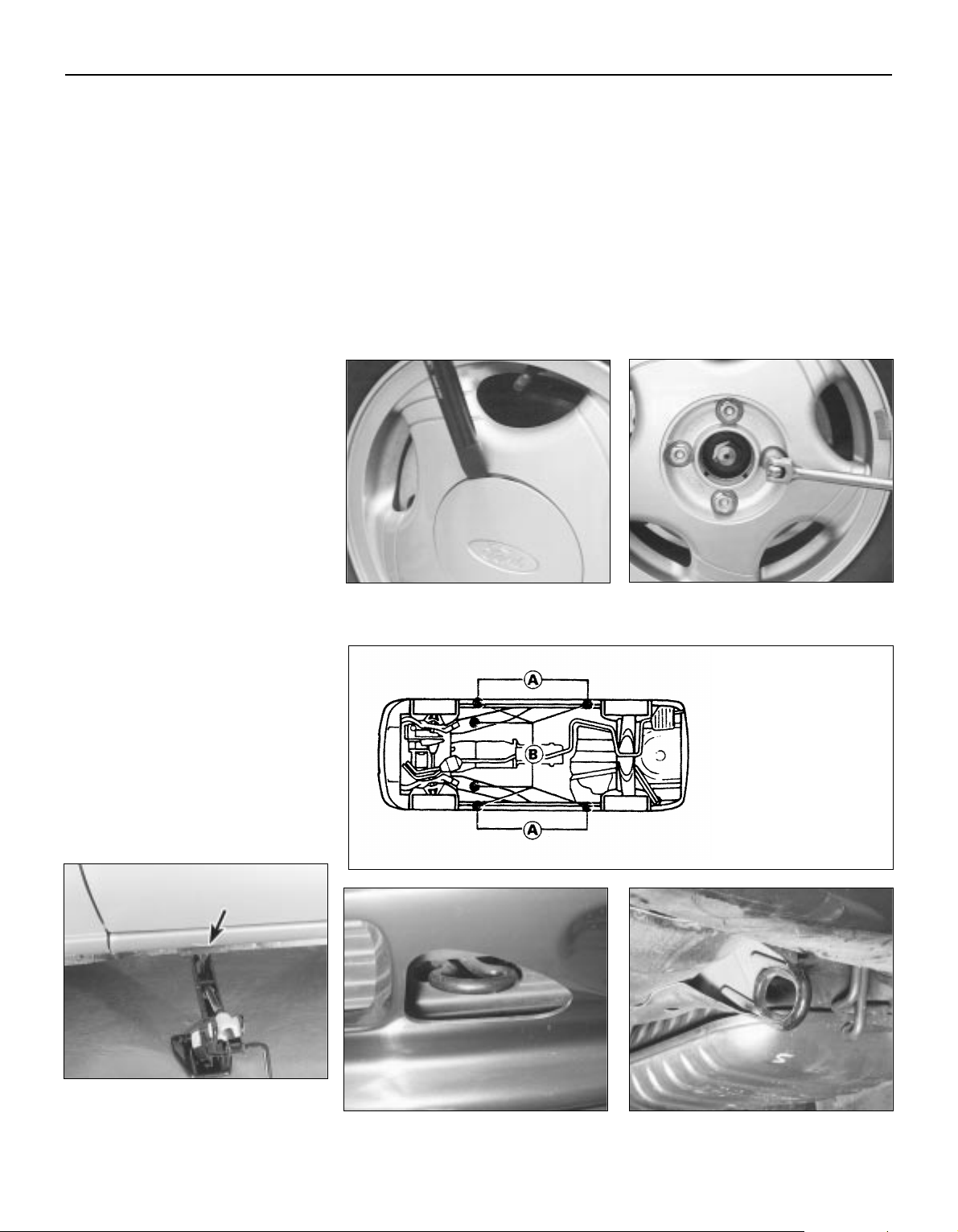
To change a wheel, remove the spare
wheel and jack, apply the handbrake, and
chock the wheel diagonally opposite the
one to be changed. On manual transmission
models, select first or reverse gear; on
automatic transmission models, place the
selector lever in “P”. Make sure that the
vehicle is located on firm level ground. Use
the flat end of the wheelbrace carefully to
remove the trim covering the wheel nuts,
then slightly loosen the wheel nuts with the
brace (see illustrations). Locate the jack
head in the jacking point nearest to the
wheel to be changed, ensuring that the
channel in the jack head fits over the body
flange (see illustrations) and turn its
handle to raise the jack. When the wheel is
clear of the ground, remove the nuts and lift
off the wheel. Fit the spare wheel, and
moderately tighten the nuts. Lower the
vehicle, then tighten the nuts fully and refit
the trim. With the spare wheel in position,
remove the chock, and stow the jack and
tools.
When jacking up the vehicle to carry out
repair or maintenance tasks, position the jack
as follows.
If the front of the vehicle is to be raised,
either place the jack head under the sump,
with a block of wood to prevent damage, or
place a jacking beam across the two front
points “B” shown in the accompanying
illustration, and lift the vehicle evenly.
To raise the rear of the vehicle, place a
jacking beam across the two rear points “B”
shown in the accompanying illustration, and
lift the vehicle evenly.
To raise the side of the vehicle, place the
jack head under the appropriate point
indicated in the accompanying illustration — if
a trolley jack or similar is used on the points
“A” provided for the vehicle’s jack, make up a
wooden spacer with a groove cut in it to
accept the underbody flange, so that there is
no risk of the jack slipping or buckling the
flange. Never work under, around or near a
raised vehicle unless it is adequately
supported in at least two places with axle
stands or suitable sturdy blocks.
The vehicle may be towed, for breakdown
recovery purposes only , using the towing eyes
positioned at the front and rear of the vehicle
(see illustrations). These eyes are intended
for towing loads only, and must not be used
for lifting the vehicle, either directly or
indirectly.
If the vehicle is equipped with automatic
transmission, the following precautions must
be observed if the vehicle is to be towed,
particularly if any kind of transmission fault is
suspected. Preferably , a fr ont-end-suspended
tow should be used (ie with the front wheels
off the ground). If this is not possible, place
the selector lever in “N” and tow the vehicle forwards only, never backwards — for a
distance of no more than 30 miles (50 km),
and at speeds no greater than 30 mph
(50 km/h).
Jacking, towing and wheel changing
Front towing eye Rear towing eye
Use flat end of wheelbrace to remove trim
covering roadwheel nuts
Slacken roadwheel nuts in diagonal
sequence
With jack base on firm ground, locate jack
head in jacking point — indentations
(arrowed) in sill identify jacking points
Jacking and supporting
points
A Jacking points (for
vehicle jack in roadside
use) — support points (for
axle stands in
servicing/overhaul work)
B Jacking points (for
trolley jack or workshop
hoist in
servicing/overhaul work)
— additional support
points
0•12
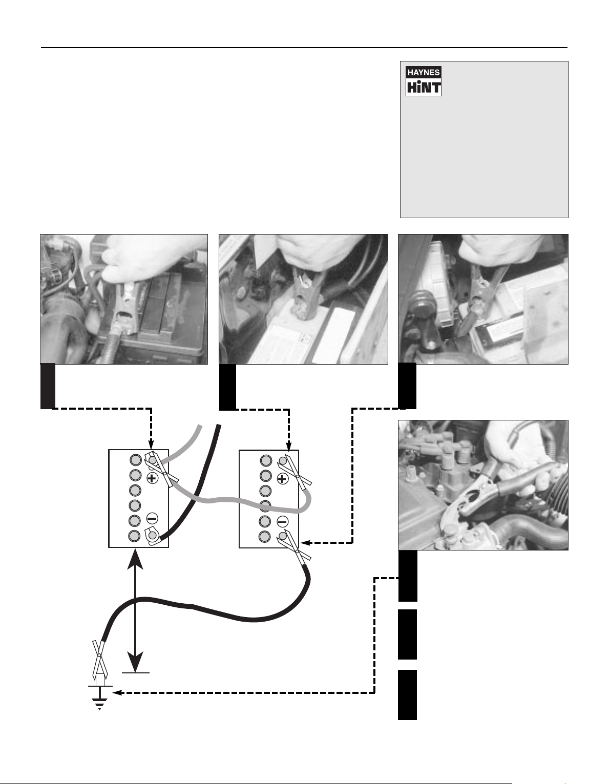
When jump-starting a car using a
booster battery, observe the following
precautions:
A) Before connecting the booster
battery, make sure that the ignition is
switched off.
B) Ensure that all electrical equipment
(lights, heater, wipers, etc) is
switched off.
C) Make sure that the booster battery is
the same voltage as the discharged
one in the vehicle.
D) If the battery is being jump-started
from the battery in another vehicle,
the two vehcles MUST NOT TOUCH
each other.
E) Make sure that the transmission is in
neutral (or PARK, in the case of
automatic transmission).
Jump starting will get you out
of trouble, but you must correct
whatever made the battery go
flat in the first place. There are
three possibilities:
1
The battery has been drained by
repeated attempts to start, or by
leaving the lights on.
2
The charging system is not working
properly (alternator drivebelt slack
or broken, alternator wiring fault or
alternator itself faulty).
3
The battery itself is at fault
(electrolyte low, or battery worn out).
Connect one end of the red jump lead to
the positive (+) terminal of the flat
battery
Connect the other end of the red lead to
the positive (+) terminal of the booster
battery.
Connect one end of the black jump lead
to the negative (-) terminal of the
booster battery
Connect the other end of the black
jump lead to a bolt or bracket on the
engine block, well away from the
battery, on the vehicle to be started.
1
2
3
4
Make sure that the jump leads will not
come into contact with the fan, drive-
belts or other moving parts of the
engine.
5
Start the engine using the booster
battery, then with the engine running at
idle speed, disconnect the jump leads in
the reverse order of connection.
6
Roadside Repairs
Booster battery (jump) starting
0•13
Roadside Repairs
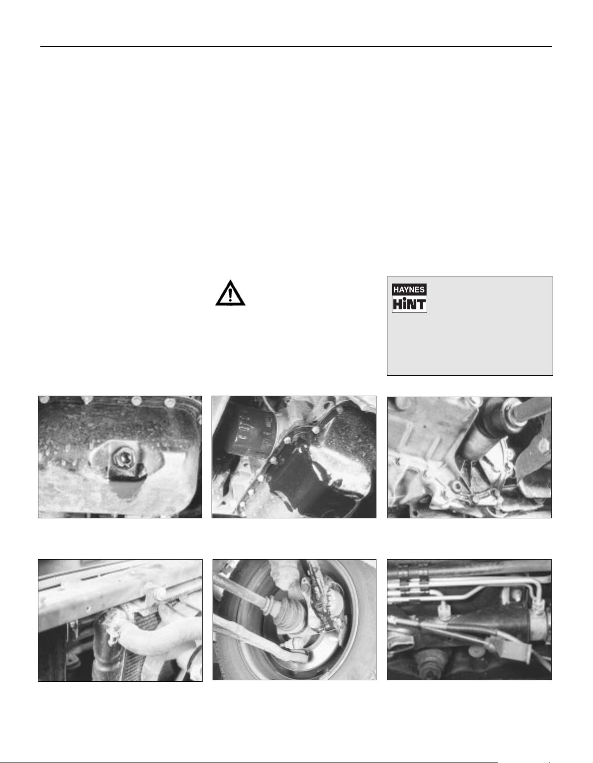
Puddles on the garage floor or drive, or
obvious wetness under the bonnet or
underneath the car, suggest a leak that needs
investigating. It can sometimes be difficult to
decide where the leak is coming from,
especially if the engine bay is very dirty
already. Leaking oil or fluid can also be blown
rearwards by the passage of air under the car,
giving a false impression of where the
problem lies.
Warning: Most automotive oils
and fluids are poisonous. Wash
them off skin, and change out of
contaminated clothing, without
delay.
Identifying leaks
The smell of a fluid leaking
from the car may provide a
clue to what’s leaking. Some
fluids are distictively coloured.
It may help to clean the car carefully
and to park it over some clean paper
overnight as an aid to locating the
source of the leak.
Remember that some leaks may only
occur while the engine is running.
Sump oil
Gearbox oil
Brake fluid Power steering fluid
Oil from filter
Antifreeze
Engine oil may leak from the drain plug… …or from the base of the oil filter.
Leaking antifreeze often leaves a crystalline
deposit like this.
Gearbox oil can leak from the seals at the
inboard ends of the driveshafts.
A leak occurring at a wheel is almost
certainly brake fluid.
Power steering fluid may leak from the pipe
connectors on the steering rack.

Length (distance)
Inches (in) x 25.4 = Millimetres (mm) x 0.0394 = Inches (in)
Feet (ft) x 0.305 = Metres (m) x 3.281 = Feet (ft)
Miles x 1.609 = Kilometres (km) x 0.621 = Miles
Volume (capacity)
Cubic inches (cu in; in3) x 16.387 = Cubic centimetres (cc; cm3) x 0.061 = Cubic inches (cu in; in3)
Imperial pints (Imp pt) x 0.568 = Litres (l) x 1.76 = Imperial pints (Imp pt)
Imperial quarts (Imp qt) x 1.137 = Litres (l) x 0.88 = Imperial quarts (Imp qt)
Imperial quarts (Imp qt) x 1.201 = US quarts (US qt) x 0.833 = Imperial quarts (Imp qt)
US quarts (US qt) x 0.946 = Litres (l) x 1.057 = US quarts (US qt)
Imperial gallons (Imp gal) x 4.546 = Litres (l) x 0.22 = Imperial gallons (Imp gal)
Imperial gallons (Imp gal) x 1.201 = US gallons (US gal) x 0.833 = Imperial gallons (Imp gal)
US gallons (US gal) x 3.785 = Litres (l) x 0.264 = US gallons (US gal)
Mass (weight)
Ounces (oz) x 28.35 = Grams (g) x 0.035 = Ounces (oz)
Pounds (lb) x 0.454 = Kilograms (kg) x 2.205 = Pounds (lb)
Force
Ounces-force (ozf; oz) x 0.278 = Newtons (N) x 3.6 = Ounces-force (ozf; oz)
Pounds-force (lbf; lb) x 4.448 = Newtons (N) x 0.225 = Pounds-force (lbf; lb)
Newtons (N) x 0.1 = Kilograms-force (kgf; kg) x 9.81 = Newtons (N)
Pressure
Pounds-force per square inch x 0.070 = Kilograms-force per square x 14.223 = Pounds-force per square inch
(psi; lbf/in2; lb/in2) centimetre (kgf/cm2; kg/cm2) (psi; lbf/in2; lb/in2)
Pounds-force per square inch x 0.068 = Atmospheres (atm) x 14.696 = Pounds-force per square inch
(psi; lbf/in2; lb/in2) (psi; lbf/in2; lb/in2)
Pounds-force per square inch x 0.069 = Bars x 14.5 = Pounds-force per square inch
(psi; lbf/in2; lb/in2) (psi; lbf/in2; lb/in2)
Pounds-force per square inch x 6.895 = Kilopascals (kPa) x 0.145 = Pounds-force per square inch
(psi; lbf/in2; lb/in2) (psi; lbf/in2; lb/in2)
Kilopascals (kPa) x 0.01 = Kilograms-force per square x 98.1 = Kilopascals (kPa)
centimetre (kgf/cm2; kg/cm2)
Millibar (mbar) x 100 = Pascals (Pa) x 0.01 = Millibar (mbar)
Millibar (mbar) x 0.0145 = Pounds-force per square inch x 68.947 = Millibar (mbar)
(psi; lbf/in2; lb/in2)
Millibar (mbar) x 0.75 = Millimetres of mercury (mmHg) x 1.333 = Millibar (mbar)
Millibar (mbar) x 0.401 = Inches of water (inH2O) x 2.491 = Millibar (mbar)
Millimetres of mercury (mmHg) x 0.535 = Inches of water (inH2O) x 1.868 = Millimetres of mercury (mmHg)
Inches of water (inH
2
O) x 0.036 = Pounds-force per square inch x 27.68 = Inches of water (inH2O)
(psi; lbf/in2; lb/in2)
Torque (moment of force)
Pounds-force inches x 1.152 = Kilograms-force centimetre x 0.868 = Pounds-force inches
(lbf in; lb in) (kgf cm; kg cm) (lbf in; lb in)
Pounds-force inches x 0.113 = Newton metres (Nm) x 8.85 = Pounds-force inches
(lbf in; lb in) (lbf in; lb in)
Pounds-force inches x 0.083 = Pounds-force feet (lbf ft; lb ft) x 12 = Pounds-force inches
(lbf in; lb in) (lbf in; lb in)
Pounds-force feet (lbf ft; lb ft) x 0.138 = Kilograms-force metres x 7.233 = Pounds-force feet (lbf ft; lb ft)
(kgf m; kg m)
Pounds-force feet (lbf ft; lb ft) x 1.356 = Newton metres (Nm) x 0.738 = Pounds-force feet (lbf ft; lb ft)
Newton metres (Nm) x 0.102 = Kilograms-force metres x 9.804 = Newton metres (Nm)
(kgf m; kg m)
Power
Horsepower (hp) x 745.7 = Watts (W) x 0.0013 = Horsepower (hp)
Velocity (speed)
Miles per hour (miles/hr; mph) x 1.609 = Kilometres per hour (km/hr; kph) x 0.621 = Miles per hour (miles/hr; mph)
Fuel consumption*
Miles per gallon (mpg) x 0.354 = Kilometres per litre (km/l) x 2.825 = Miles per gallon (mpg)
Temperature
Degrees Fahrenheit = (°C x 1.8) + 32 Degrees Celsius (Degrees Centigrade; °C) = (°F — 32) x 0.56
* It is common practice to convert from miles per gallon (mpg) to litres/100 kilometres (l/100km), where mpg x l/100 km = 282

Chapter 1 Routine maintenance and servicing
Air conditioning system check . . . . . . . . . . . . . . . . . . . . . . . . . . . . . 14
Air filter element renewal . . . . . . . . . . . . . . . . . . . . . . . . . . . . . . . . . . 29
Automatic transmission fluid level check . . . . . . . . . . . . . . . . . . . . . 7
Automatic transmission linkage lubrication . . . . . . . . . . . . . . . . . . . 18
Auxiliary drivebelt check and renewal . . . . . . . . . . . . . . . . . . . . . . . . 11
Battery check, maintenance and charging . . . . . . . . . . . . . . . . . . . . 9
Brake check . . . . . . . . . . . . . . . . . . . . . . . . . . . . . . . . . . . . . . . . . . . 23
Brake fluid renewal . . . . . . . . . . . . . . . . . . . . . . . . . . . . . . . . . . . . . . 34
Clutch pedal adjustment . . . . . . . . . . . . . . . . . . . . . . . . . . . . . . . . . . 17
Coolant renewal . . . . . . . . . . . . . . . . . . . . . . . . . . . . . . . . . . . . . . 2, 28
Door and bonnet check and lubrication . . . . . . . . . . . . . . . . . . . . . . 24
Driveshaft rubber gaiter and CV joint check . . . . . . . . . . . . . . . . . . . 20
Electrical system check . . . . . . . . . . . . . . . . . . . . . . . . . . . . . . . . . . . 8
Engine compartment wiring check . . . . . . . . . . . . . . . . . . . . . . . . . . 13
Engine oil and filter change . . . . . . . . . . . . . . . . . . . . . . . . . . . . . . . . 15
Exhaust system check . . . . . . . . . . . . . . . . . . . . . . . . . . . . . . . . . . . 21
Fluid level checks . . . . . . . . . . . . . . . . . . . . . . . . . . . . . . . . . . . . . . . 3
Fuel filter renewal . . . . . . . . . . . . . . . . . . . . . . . . . . . . . . . . . . . . . . . 33
Idle speed and mixture check and adjustment . . . . . . See Chapter 4
Ignition timing check . . . . . . . . . . . . . . . . . . . . . . . . . . See Chapter 5
Introduction . . . . . . . . . . . . . . . . . . . . . . . . . . . . . . . . . . . . . . . . . . . . 1
Manual transmission oil level check . . . . . . . . . . . . . . . . . . . . . . . . . 16
Positive Crankcase Ventilation (PCV) system check
and filter cleaning . . . . . . . . . . . . . . . . . . . . . . . . . . . . . . . . . . . . . 30
Power steering fluid level check . . . . . . . . . . . . . . . . . . . . . . . . . . . . 5
Road test . . . . . . . . . . . . . . . . . . . . . . . . . . . . . . . . . . . . . . . . . . . . . . 26
Roadwheel nut tightness check . . . . . . . . . . . . . . . . . . . . . . . . . . . . 25
Seat belt check . . . . . . . . . . . . . . . . . . . . . . . . . . . . . . . . . . . . . . . . . 10
Spark plug renewal . . . . . . . . . . . . . . . . . . . . . . . . . . . . . . . . . . . . . . 31
Specifications . . . . . . . . . . . . . . . . . . . . . . . . . . . . See end of Chapter
Steering, suspension and roadwheel check . . . . . . . . . . . . . . . . . . . 19
Timing belt renewal . . . . . . . . . . . . . . . . . . . . . . . . . . . . . . . . . . . . . . 32
Tyre and tyre pressure checks . . . . . . . . . . . . . . . . . . . . . . . . . . . . . 4
Underbody and fuel/brake line check . . . . . . . . . . . . . . . . . . . . . . . . 22
Underbonnet check for fluid leaks and hose condition . . . . . . . . . . 12
Ventilation system pollen filter renewal . . . . . . . . . . . . . . . . . . . . . . . 27
Windscreen/tailgate washer system and wiper blade check . . . . . . 6
1•1
Easy, suitable for
novice with little
experience
Fairly easy, suitable
for beginner with
some experience
Fairly difficult, suitable
for competent DIY
mechanic
Difficult, suitable for
experienced DIY
mechanic
Very difficult,
suitable for expert DIY
or professional
Degrees of difficulty
Contents
1
1•2
Lubricants, Fluids & Capacities
Lubricants and fluids
Component or system Lubricant type/specification
Engine Multigrade engine oil to specification API SG/CD or better, viscosity range 5W/50 to 10W/30
Manual transmission Gear oil to Ford specification ESD-M2C-186-A
Automatic transmission Transmission fluid to Ford specification ESP-M2C-166-H
Power steering Transmission fluid to Ford specification ESP-M2C-166-H
Cooling system Soft water, and antifreeze (ethylene glycol-based, suitable for use in mixed-metal cooling systems) to
Ford specification ESD-M97B-49-A
Braking system Hydraulic fluid to Ford specification ESD-M6C-57-A, Super DOT 4 or equivalent
Driveshaft joints Long-life grease to Ford specification SQM-1C 9004-A
Capacities
Engine oil:
At oil and filter change . . . . . . . . . . . . . . . . . . . . . . . 4.25 litres
Dry — at engine overhaul . . . . . . . . . . . . . . . . . . . . . . 4.50 litres
Difference between dipstick minimum and
maximum level notches . . . . . . . . . . . . . . . . . . . . . . 0.5 to 1.0 litre
Fuel tank . . . . . . . . . . . . . . . . . . . . . . . . . . . . . . . . . . . 61.5 litres
Cooling system:
Manual transmission models . . . . . . . . . . . . . . . . . . 6.6 litres
Automatic transmission models . . . . . . . . . . . . . . . 7.1 litres
Manual transmission . . . . . . . . . . . . . . . . . . . . . . . . . . 2.6 litres
Automatic transmission:
Total, including fluid cooler . . . . . . . . . . . . . . . . . . . 7.2 litres
Drain and refill . . . . . . . . . . . . . . . . . . . . . . . . . . . . . 3.6 litres

Ford Mondeo maintenance schedule
1•3
1
Maintenance schedule
The manufacturer’s recommended maintenance schedule for these
vehicles is as described below — note that the schedule starts from the
vehicle’s date of registration. These are the minimum maintenance
intervals recommended by the factory for Mondeos driven daily, but
subjected only to “normal” use. If you wish to keep your vehicle in
peak condition at all times, you may wish to perform some of these
procedures even more often. Because frequent maintenance
enhances the efficiency, performance and resale value of your vehicle,
we encourage you to do so. If your usage is not “normal”, shorter
intervals are also recommended — the most important examples of
these are noted in the schedule. These shorter intervals apply
particularly if you drive in dusty areas, tow a caravan or trailer, sit with
the engine idling or drive at low speeds for extended periods (ie, in
heavy traffic), or drive for short distances (less than four miles) in
below-freezing temperatures.
When your vehicle is new, it should be serviced by a Ford dealer
service department to protect the factory warranty. In many cases, the
initial maintenance check is done at no cost to the owner. Note that
this first free service (carried out by the selling dealer 1500 miles or 3
months after delivery), although an important check for a new vehicle,
is not part of the regular maintenance schedule, and is therefore not
mentioned here.
Weekly checks
mm Check the engine oil level, and top-up if necessary
(Section 3)
mm Check the brake fluid level, and top-up if necessary
(Section 3). If repeated topping-up is required, check the
system for leaks or damage at the earliest possible
opportunity (Sections 12 and 22)
mm Check the windscreen/tailgate washer fluid level, and top-
up if necessary (Section 3)
mm Check the tyre pressures, including the spare (Section 4)
mm Visually check the tyres for excessive tread wear, or
damage (Section 4)
mm Check the operation of all (exterior and interior) lights and
the horn, wipers and windscreen/tailgate washer system
(Sections 6 and 8). Renew any blown bulbs (Chapter 12),
and clean the lenses of all exterior lights
Monthly checks
mm Check the coolant level, and top-up if necessary (Sec-
tion 3)
mm Check the battery electrolyte level, where applicable
(Section 3)
mm Check the power steering fluid level, and top-up if
necessary (Section 5)
mm Visually check all reservoirs, hoses and pipes for leakage
(Section 12)
mm Check the operation of the air conditioning system
(Section 14)
mm Check the operation of the handbrake (Section 23)
mm Check the aim of the windscreen/tailgate/headlight
washer jets, correcting them if required (Section 6)
mm Check the condition of the wiper blades, renewing them if
worn or no longer effective — note that the manufacturer
recommends renewing the blades as a safety precaution,
irrespective of their apparent condition, at least once a
year (Section 6)
Every 10 000 miles or 12 months,
whichever occurs first
Note: If the vehicle is used regularly for very short (less than
10 miles), stop/go journeys, the oil and filter should be renewed
between services (ie, every 5000 miles/6 months).
mm Check the electrical system (Section 
mm Check the battery (Section 9)
mm Check the seat belts (Section 10)
mm Check the auxiliary drivebelt (Section 11)
mm Check for fluid leaks and hose condition (Section 12)
mm Check the condition of all wiring (Section 13)
mm Check all air conditioning components (Section 14)
mm Change the engine oil and filter (Section 15)
mm Check the manual transmission oil level (Section 16)
mm Check the adjustment of the clutch pedal (Section 17)
mm Lubricate the automatic transmission linkage (Section 18)
mm Check the steering, suspension and wheels (Section 19)
mm Check the driveshaft gaiters and CV joints (Section 20)
mm Check the exhaust system (Section 21)
mm Check the underbody, and all fuel/brake lines (Section 22)
mm Check the brake system (Section 23)
mm Check and lubricate the doors and bonnet (Section 24)
mm Check the security of all roadwheel nuts (Section 25)
mm Road test (Section 26). Check the level of the automatic
transmission fluid with the engine still hot, after the road
test (Section 7)
Every 20 000 miles or 2 years,
whichever occurs first
Carry out all operations listed above, plus the following:
mm Renew the ventilation system pollen filter (Section 27)
mm Renew the coolant (Sections 2 and 28)
Every 30 000 miles or 3 years,
whichever occurs first
Carry out all operations listed above, plus the following:
mm Renew the air filter element (Section 29). Note that this
task must be carried out at more frequent intervals if the
vehicle is used in dusty or polluted conditions
mm Check the Positive Crankcase Ventilation (PCV) system,
and clean the filter (Section 30)
mm Renew the spark plugs (Section 31)
Every 60 000 miles
Carry out all operations listed above, plus the following:
mm Renew the timing belt (Section 32)
mm Renew the fuel filter (Section 33)
Every 3 years
(regardless of mileage)
mm Renew the brake fluid (Section 34)
1•4
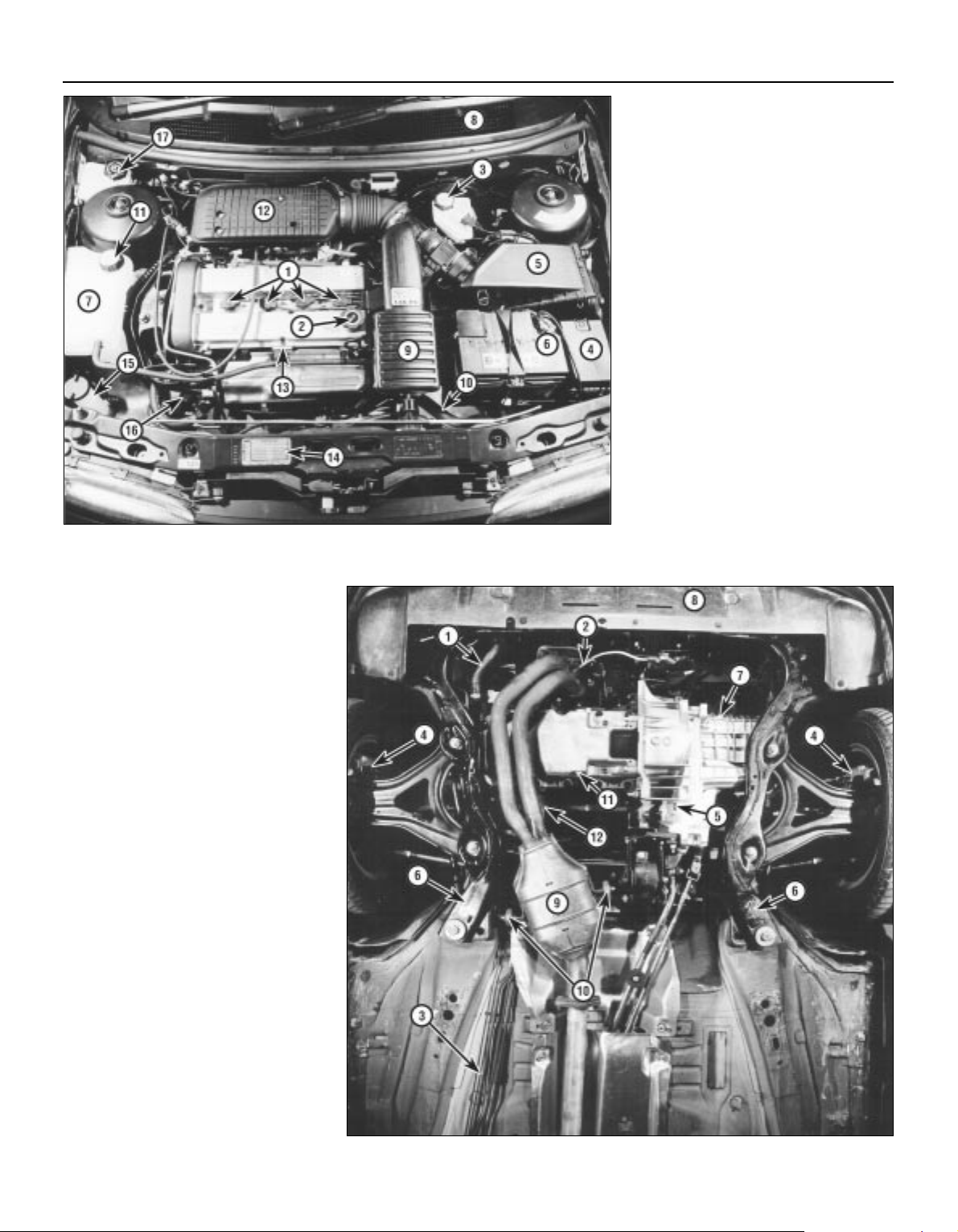
Engine compartment components
1 Spark plugs (Section 31)
2 Engine oil filler cap (Section 3)
3 Brake fluid reservoir (Section 3)
4 Auxiliary fusebox (Chapter 12)
5 Air cleaner assembly (Section 29)
6 Battery (Section 9)
7 Cooling system expansion tank
(Section 28)
8 Ventilation system pollen filter — under
cowl grille panel (Section 27)
9 Air intake resonator (Chapter 4)
10 Radiator top hose (Section 12)
11 Cooling system expansion tank filler cap
(Section 3)
12 Air intake plenum chamber (Chapter 4)
13 Engine oil dipstick (Section 3)
14 Vehicle Identification Number (VIN) plate
15 Windscreen/tailgate washer fluid reservoir
(Section 3)
16 Auxiliary drivebelt (Section 11)
17 Power steering fluid reservoir (Section 5)
Front underbody view
1 Radiator bottom hose (Section 12)
2 Exhaust gas oxygen sensor (Chapter 6)
3 Braking system, fuel and emission control
system lines (Section 22)
4 Front disc brake (Section 23)
5 Manual transmission drain plug
(Chapter 7, Part A)
6 Front suspension subframe (Chapter 2,
Part B)
7 Manual transmission filler/level plug
(Section 16)
8 Radiator undershield (Section 28)
9 Catalytic converter (Section 21)
10 Exhaust system rubber mountings
(Section 21)
11 Engine oil drain plug (Section 15)
12 Engine oil filter (Section 15)
Maintenance procedures
1•5
1
Maintenance procedures
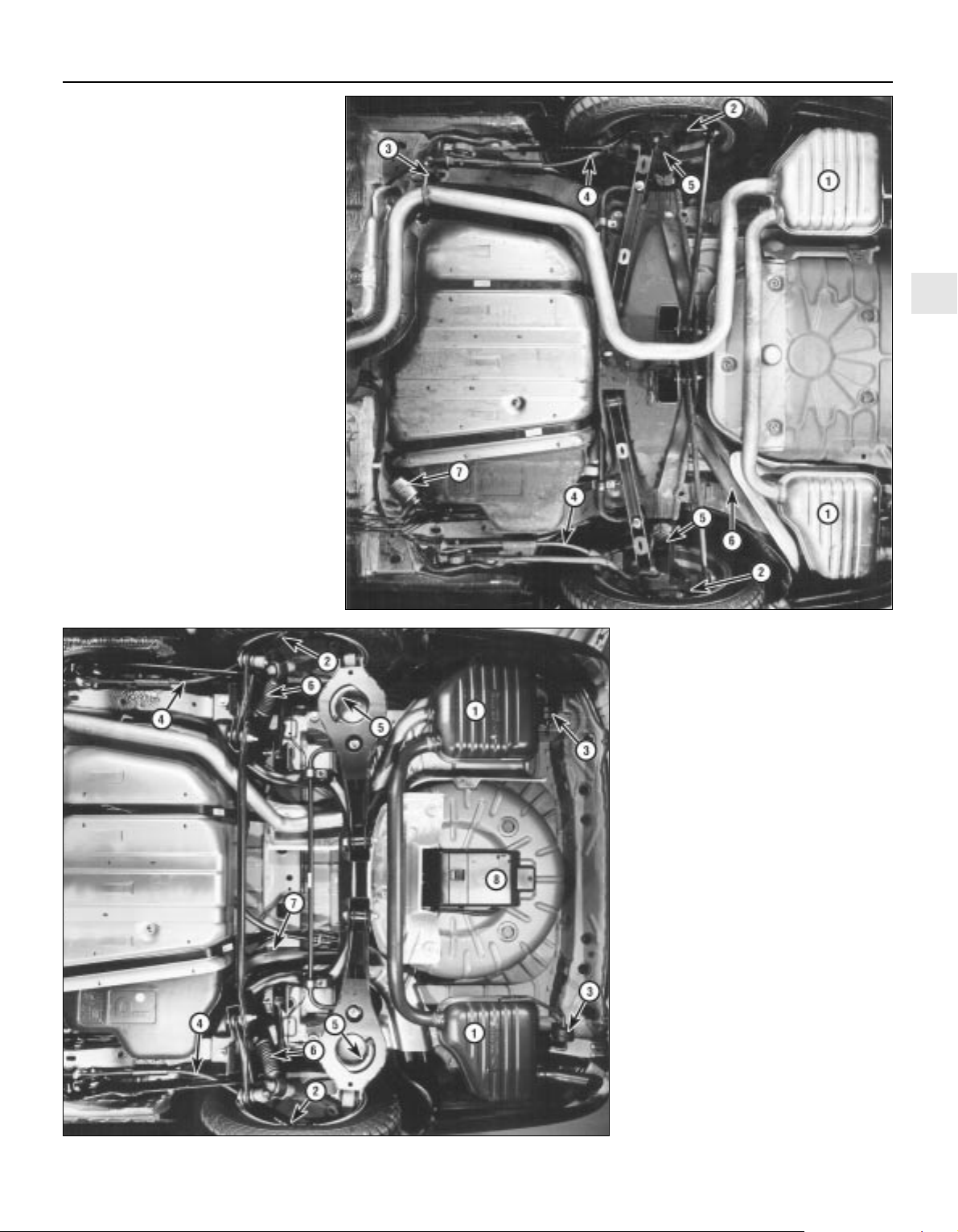
Rear underbody view — Saloon and
Hatchback models
1 Silencers (Section 21)
2 Rear brakes (Section 23)
3 Exhaust system rubber mounting
(Section 21)
4 Handbrake cables (Section 23)
5 Suspension struts and springs
(Section 19)
6 Fuel tank filler neck (Section 22)
7 Fuel filter (Section 33)
Rear underbody view — Estate models
1 Silencers (Section 21)
2 Rear brakes (Section 23)
3 Exhaust system rubber mounting
(Section 21)
4 Handbrake cables (Section 23)
5 Suspension springs (Section 19)
6 Suspension shock absorbers (Section 19)
7 Fuel tank filler neck (Section 22)
8 Evaporative emissions control system
charcoal canister (Chapter 6)
This Chapter is designed to help the home
mechanic maintain the Ford Mondeo models
for peak performance, economy, safety and
long life.
On the following pages are Sections
dealing specifically with each item on the
maintenance schedule. Visual checks,
adjustments, component replacement and
other helpful items are included. Refer to the
accompanying illustrations of the engine
compartment and the underside of the vehicle
for the location of various components.
Servicing your Mondeo in accordance with
the mileage/time maintenance schedule and
the following Sections will provide it with a
planned maintenance programme, which
should result in a long and reliable service life.
This is a comprehensive plan, so maintaining
some items but not others at the specified
service intervals will not produce the same
results.
As you service your Mondeo, you will
discover that many of the procedures can and should — be grouped together, because of
the nature of the particular procedure you’re
performing, or because of the close proximity
to one another of two otherwise-unrelated
components.
For example, if the vehicle is raised for any
reason, you should inspect the exhaust,
suspension, steering and fuel systems while
you’re under the vehicle. When you’re
checking the tyres, it makes good sense to
check the brakes and wheel bearings,
especially if the roadwheels have already
been removed.
Finally, let’s suppose you have to borrow or
hire a torque wrench. Even if you only need to
tighten the spark plugs, you might as well
check the torque of as many critical fasteners
as time allows.
The first step of this maintenance
programme is to prepare yourself before the
actual work begins. Read through all the
Sections which are relevant to the procedures
you’re planning to carry out, then make a list
of, and gather together, all the parts and tools
you will need to do the job. If it looks as if you
might run into problems during a particular
segment of some procedure, seek advice
from your local parts man or dealer service
department.
Ford state that, where antifreeze to
specification ESD-M97B-49-A (the type with
which the vehicle’s cooling system would
have been filled on production at the factory)
is used, it will last the lifetime of the vehicle.
This is subject to it being used in the
recommended concentration, unmixed with
any other type of antifreeze or additive, and
topped-up when necessary using only that
antifreeze mixed 50/50 with clean water. If any
other type of antifreeze is added, the lifetime
guarantee no longer applies; to restore the
lifetime protection, the system must be
drained and thoroughly reverse-flushed
before fresh coolant mixture is poured in.
If the vehicle’s history (and therefore the
quality of the antifreeze in it) is unknown,
owners who wish to follow Ford’s
recommendations are advised to drain and
thoroughly reverse-flush the system, as
outlined in Section 28, before refilling with
fresh coolant mixture. If the appropriate
quality of antifreeze is used, the coolant can
then be left for the life of the vehicle.
If any antifreeze other than Ford’s is to be
used, the coolant must be renewed at regular
intervals to provide an equivalent degree of
protection; the conventional recommendation
is to renew the coolant every two years.
The above assumes the use of a mixture (in
exactly the specified concentration) of clean,
soft water and of antifreeze to Ford’s
specification or equivalent. It is also assumed
that the cooling system is maintained in a
scrupulously-clean condition, by ensuring that
only clean coolant is added on topping-up,
and by thorough reverse-flushing whenever
the coolant is drained (Section 28).
2 Coolant renewal
1 Introduction
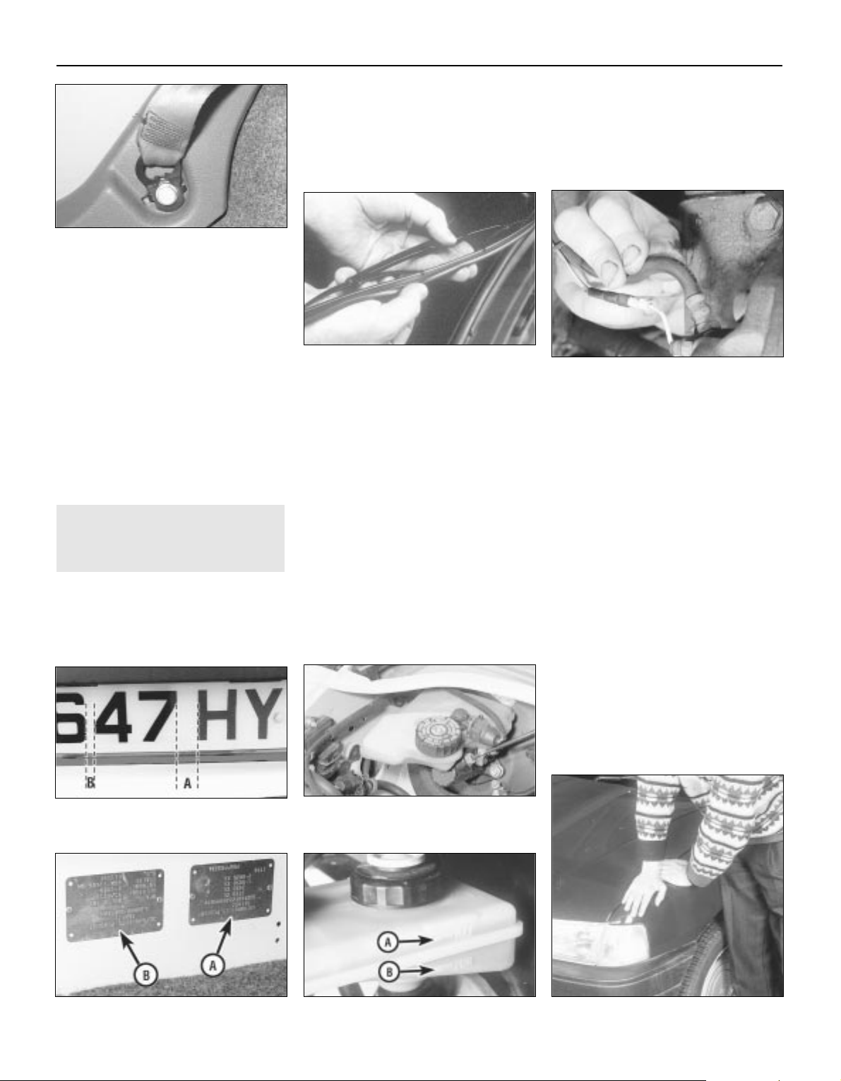
1•6
Weekly checks
Weekly checks
General
1 Fluids are an essential part of the
lubrication, cooling, braking and other
systems. Because these fluids gradually
become depleted and/or contaminated during
normal operation of the vehicle, they must be
periodically replenished. See “Lubricants and
fluids and capacities” at the beginning of this
Chapter before adding fluid to any of the
following components. Note: The vehicle
must be on level ground before fluid levels can
be checked.
Engine oil
2 The engine oil level is checked with a
dipstick located at the front of the engine; it
can be identified by its yellow/black plastic
grip (see illustration). The dipstick extends
through a metal tube, from which it protrudes
down into the sump at the bottom of the
engine.
3 The oil level should be checked before the
vehicle is driven, or about 5 minutes after the
engine has been switched off.
4 Pull the dipstick from the tube, and wipe all
the oil from the end with a clean rag or paper
towel; note the dipstick’s maximum and
minimum levels, indicated by notches (see
illustration). Insert the clean dipstick all the way
back into its metal tube, and pull it out again.
Observe the oil on the end of the dipstick; its
level should be between these two notches.
5 Do not allow the level to drop below the
minimum level notch, or oil starvation may
cause engine damage. Conversely, overfilling
the engine (adding oil above the maximum
level notch) may cause oil-fouled spark plugs,
oil leaks or oil seal failures.
6 The yellow/black plastic oil filler cap is
screwed into the left-hand front end of the
3 Fluid level checks
3.2 The engine oil dipstick (arrowed) is
located at the front of the engine — note
yellow/black plastic grip
3.4 The oil level should be at or near the
maximum level notch (A) — if not, add
enough oil to correct the level. It takes
approximately 0.5 to 1.0 litre of oil to raise
the level from the minimum level notch (B)
to the maximum
If the level is checked
immediately after driving the
vehicle, some of the oil will
remain in the engine upper
components, producing an inaccurate
dipstick reading.
cylinder head cover; unscrew it to add oil (see
illustration). When topping-up, use only the
correct grade and type of oil, as given in the
Specifications Section of this Chapter; use a
funnel if necessary to prevent spills. It takes
approximately 0.5 to 1.0 litre of oil to raise the
level from the dipstick’s minimum level notch
to its maximum level notch. After adding the
oil, refit the filler cap hand-tight. Start the
engine, and allow it to idle while the oil is
redistributed around the engine — while you
are waiting, look carefully for any oil leaks,
particularly around the oil filter or drain plug.
Stop the engine; check the oil level again,
after the oil has had enough time to drain from
the upper block and cylinder head galleries.
7 Checking the oil level is an important
preventive maintenance step. A continuallydropping oil level indicates oil leakage through
damaged seals and from loose connections,
or oil consumption past worn piston rings or
valve guides. If the oil looks milky in colour, or
has water droplets in it, the cylinder head
gasket may be blown — the engine’s
compression pressure should be checked
immediately (see Chapter 2A). The condition
of the oil should also be checked. Each time
you check the oil level, slide your thumb and
index finger up the dipstick before wiping off
the oil. If you see small dirt or metal particles
clinging to the dipstick, the oil should be
changed (Section 15).
Coolant
Warning: Do not allow antifreeze
to come in contact with your skin
or painted surfaces of the
vehicle. Flush contaminated areas
immediately with plenty of water. Don’t
store new coolant, or leave old coolant
lying around, where it’s accessible to
children or pets — they’re attracted by its
sweet smell. Ingestion of even a small
amount of coolant can be fatal! Wipe up
garage-floor and drip-pan spills
immediately. Keep antifreeze containers
covered, and repair cooling system leaks
as soon as they’re noticed.
8 All vehicles covered by this manual are
equipped with a sealed, pressurised cooling
system. A translucent plastic expansion tank,
located on the right-hand side of the engine
compartment, is connected by a hose to the
thermostat housing. As the coolant heats up
during engine operation, surplus coolant
passes through the connecting hose into the
expansion tank; a connection to the radiator
bottom hose union allows coolant to circulate
through the tank and back to the water pump,
thus purging any air from the system. As the
engine cools, the coolant is automatically
drawn back into the cooling system’s main
components, to maintain the correct level.
9 While the coolant level must be checked
regularly, remember therefore that it will vary
with the temperature of the engine. When the
engine is cold, the coolant level should be
between the “MAX” and “MIN” level lines on
the tank, but once the engine has warmed up,
the level may rise to above the “MAX” level
line.
10 For an accurate check of the coolant
level, the engine must be cold. The level must
be between the “MAX” and “MIN” level lines
on the tank (see illustration). If it is below the
“MIN” level line, the coolant must be toppedup as follows.
11 First prepare a sufficient quantity of
coolant mixture, using clean, soft water and
antifreeze of the recommended type, in the
specified mixture ratio. If you are using
antifreeze to Ford’s specification or equivalent
(see the note at the beginning of Section 2 of
this Chapter), mix equal quantities of water
and antifreeze to produce the 50/50 mixture
ratio specified when topping-up; if using any
other type of antifreeze, follow its
manufacturer’s instructions to achieve the
correct ratio. If only a small amount of coolant
is required to bring the system up to the
proper level, plain water can be used, but
repeatedly doing this will dilute the
antifreeze/water solution in the system,
reducing the protection it should provide
against freezing and corrosion. To maintain
the specified antifreeze/water ratio, it is
essential to top-up the coolant level with the
correct mixture, as described here. Use only
ethylene/glycol type antifreeze, and do not
use supplementary inhibitors or additives.
Warning: Never remove the
expansion tank filler cap when
the engine is running, or has just
been switched off, as the cooling system
will be hot, and the consequent escaping
steam and scalding coolant could cause
serious injury.
12 If topping-up is necessary, wait until the
system has cooled completely (or at least 10
minutes after switching off the engine, if lack
of time means it is absolutely necessary to
top-up while the engine may still be warm).
Wrap a thick cloth around the expansion tank
filler cap, and unscrew it one full turn. If any
hissing is heard as steam escapes, wait until
the hissing ceases, indicating that pressure is
released, then slowly unscrew the filler cap
until it can be removed. If more hissing
sounds are heard, wait until they have
stopped before unscrewing the filler cap
completely. At all times, keep your face,
hands and other exposed skin well away from
the filler opening.
13 When the filler cap has been removed,
add coolant to bring the level up to the “MAX”
level line (see illustration). Refit the cap,
tightening it securely.
14 With this type of cooling system, the
addition of coolant should only be necessary at
very infrequent intervals. If topping-up is
regularly required, or if the coolant level drops
within a short time after replenishment, there
may be a leak in the system. Inspect the
radiator, hoses, expansion tank filler cap,
radiator drain plug and water pump. If no leak is
evident, have the filler cap and the entire
system pressure-tested by your dealer or
suitably-equipped garage; this will usually show
up a small leak not otherwise visible. If
significant leakage is found at any time, use an
antifreeze hydrometer to check the concentration of antifreeze remaining in the coolant.
1•7
1
3.13 Remove the cap to add coolant only
when the engine is cold — top-up to the
“MAX” level line using the specified
coolant mixture
3.6 The yellow/black oil filler cap is
screwed into the cylinder head cover.
Always make sure the area around the
opening is clean before unscrewing the
cap, to prevent dirt from contaminating the
engine
3.10 The cooling system expansion tank is
located on the right-hand side of the
engine compartment. The coolant level
must be between the tank “MAX” and
“MIN” level lines (arrowed) when the
engine is cold
Weekly checks
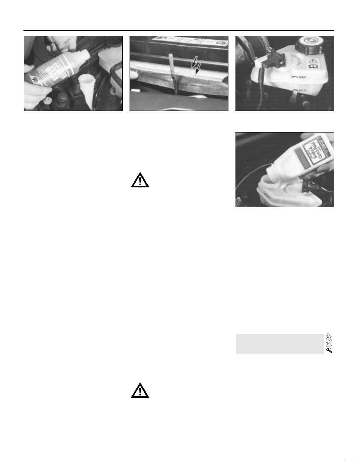
15 Coolant hydrometers are available at
most automotive accessory shops. If the
specific gravity of a sample taken from the
expansion tank (when the engine is switched
off and fully cooled down) is less than that
specified, the coolant mixture strength has
fallen below the minimum. If this is found,
either the coolant strength must be restored
by adding neat antifreeze to Ford’s
specification (if that is what is in the system)
or by draining and flushing the system, then
refilling it with fresh coolant mixture of the
correct ratio (if any other type of antifreeze is
being used).
16 When checking the coolant level, always
note its condition; it should be relatively clear.
If it is brown or rust-coloured, the system
should be drained, flushed and refilled. If
antifreeze has been used which does not
meet Ford’s specification, its corrosion
inhibitors will lose their effectiveness with
time; such coolant must be renewed regularly,
even if it appears to be in good condition,
usually at the intervals suggested at the
beginning of Section 2 of this Chapter.
Windscreen/tailgate and
headlight washer fluid
17 Fluid for the windscreen/tailgate washer
system (and where applicable the headlight
washer system) is stored in a plastic reservoir,
which is located at the right front corner of the
engine compartment. In milder climates, plain
water can be used to top-up the reservoir, but
the reservoir should be kept no more than
two-thirds full, to allow for expansion should
the water freeze. In colder climates, the use of
a specially-formulated windscreen washer
fluid, available at your dealer or any car
accessory shop, will help lower the freezing
point of the fluid (see illustration). Do not use
regular (engine) antifreeze — it will damage the
vehicle’s paintwork.
Battery electrolyte
18 On models not equipped with a sealed
battery (see Section 9), check the electrolyte
level of all six battery cells. The level must be
approximately 10 mm above the plates; this
may be shown by maximum and minimum
level lines marked on the battery’s casing (see
illustration). If the level is low, use a coin to
release the filler/vent cap, and add distilled
water. Install and securely retighten the cap.
Caution: Overfilling the cells may
cause electrolyte to spill over
during periods of heavy charging,
causing corrosion or damage.
Refer also to the warning at the beginning
of Section 9.
Brake fluid
19 The brake fluid reservoir is located on the
top of the brake master cylinder, which is
attached to the front of the vacuum servo unit.
The “MAX” and “MIN” marks are indicated on
the side of the translucent reservoir, and the
fluid level should be maintained between
these marks at all times (see illustration).
20 The brake fluid inside the reservoir is
readily visible. With the vehicle on level
ground, the level should normally be on or just
below the “MAX” mark.
21 Progressive wear of the brake pads and
brake shoe linings causes the level of the
brake fluid to gradually fall; however, when
the brake pads are renewed, the original level
of the fluid is restored. It is not therefore
necessary to top-up the level to compensate
for this minimal drop, but the level must never
be allowed to fall below the minimum mark.
22 If topping-up is necessary, first wipe the
area around the filler cap with a clean rag
before removing the cap. When adding fluid,
pour it carefully into the reservoir, to avoid
spilling it on surrounding painted surfaces
(see illustration). Be sure to use only the
specified hydraulic fluid (see “Lubricants,
fluids and capacities” at the start of this
Chapter) since mixing different types of fluid
can cause damage to the system.
Warning: Brake hydraulic fluid
can harm your eyes and damage
painted surfaces, so use extreme
caution when handling and
pouring it. Wash off spills immediately with
plenty of water. Do not use fluid that has
been standing open for some time, as it
absorbs moisture from the air. Excess
moisture can cause corrosion and a
dangerous loss of braking effectiveness.
23 When adding fluid, it is a good idea to
inspect the reservoir for contamination. The
system should be drained and refilled if
deposits, dirt particles or contamination are
seen in the fluid.
24 After filling the reservoir to the correct
level, make sure that the cap is refitted
securely, to avoid leaks and the entry of
foreign matter.
25 If the reservoir requires repeated
replenishing to maintain the correct level, this
is an indication of an hydraulic leak
somewhere in the system, which should be
investigated immediately.
Power steering fluid
26 See Section 5 of this Chapter.
1 Periodic inspection of the tyres may spare
you from the inconvenience of being stranded
with a flat tyre. It can also provide you with
vital information regarding possible problems
in the steering and suspension systems
before major damage occurs.
2 The original tyres on this vehicle are
equipped with tread wear indicator (TWI)
bands, which will appear when the tread
depth reaches approximately 1.6 mm. Most
tyres have a mark around the tyre at regular
intervals to indicate the location of the tread
4 Tyre and tyre pressure checks
1•8
3.17 Topping-up the windscreen washer
reservoir
3.18 On non-sealed batteries, keep the
electrolyte level of all the cells in the
battery between the maximum and
minimum levels (arrowed) — ie, 10 mm
above the plates. Use only distilled water,
and never overfill
3.19 Brake fluid reservoir, showing “MAX”
and “MIN” marks
3.22 Topping-up the brake fluid reservoir
Weekly checks
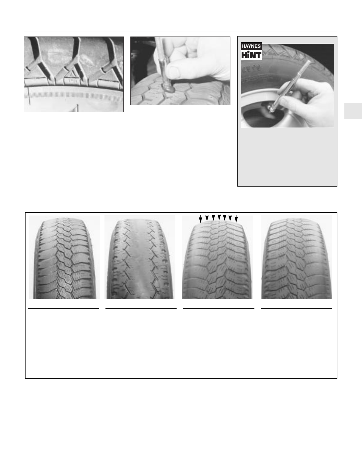
wear indicators, the mark being TWI, an
arrow, or the tyre manufacturer’s symbol (see
illustration). Tread wear can also be
monitored with a simple inexpensive device
known as a tread depth indicator gauge (see
illustration).
3 Ensure that tyre pressures are checked
regularly and maintained correctly (see the
Specifications at the beginning of this Chapter
for pressures). Checking should be carried out
with the tyres cold, and not immediately after
the vehicle has been in use. If the pressures
are checked with the tyres hot, an apparentlyhigh reading will be obtained, owing to heat
expansion. Under no circumstances should an
attempt be made to reduce the pressures to
the quoted cold reading in this instance, or
effective under-inflation will result.
1•9
1
Tyre Tread Wear Patterns
Shoulder Wear
Underinflation
(wear on both sides)
Check and adjust pressures
Incorrect wheel camber
(wear on one side)
Repair or renew suspension
parts
Hard cornering
Reduce speed!
Centre Wear
Overinflation
Check and adjust pressures
If you sometimes have to inflate
your car’s tyres to the higher
pressures specified for maximum
load or sustained high speed,
don’t forget to reduce the pressures to normal afterwards.
Toe Wear
Incorrect toe setting
Adjust front wheel alignment
Note: The feathered edge of
the tread which characterises
toe wear is best checked by
feel.
Uneven Wear
Incorrect camber or castor
Repair or renew suspension
parts
Malfunctioning suspension
Repair or renew suspension
parts
Unbalanced wheel
Balance tyres
Out-of-round brake disc/drum
Machine or renew
4.2A The TWI mark on the side of the tyre
shows the position of the tread wear
indicator bands
4.2B A tyre tread depth indicator should
be used to monitor tyre wear — they are
available at accessory shops and service
stations, and cost very little
Weekly checks
Most garage forecourts have a
pressure line which combines a gauge
to check and adjust the tyre pressures,
but they may vary in accuracy, due to
general misuse and abuse. It therefore
pays to carry a good-quality tyre
pressure gauge in the vehicle, to make
the regular checks required and ensure
pressure accuracy.
4 Note any abnormal tread wear (see
illustration). Tread pattern irregularities such
as feathering, flat spots, and more wear on
one side than the other, are indications of
front wheel alignment and/or balance
problems. If any of these conditions are
noted, they should be rectified as soon as
possible.
5 Under-inflation will cause overheating of the
tyre, owing to excessive flexing of the casing,
and the tread will not sit correctly on the road
surface. This will cause a consequent loss of
adhesion and excessive wear, not to mention
the danger of sudden tyre failure due to heat
build-up.
6 Over-inflation will cause rapid wear of the
centre part of the tyre tread, coupled with
reduced adhesion, harder ride, and the
danger of damage occurring in the tyre
casing.
7 Regularly check the tyres for damage in the
form of cuts or bulges, especially in the
sidewalls. Remove any nails or stones
embedded in the tread, before they penetrate
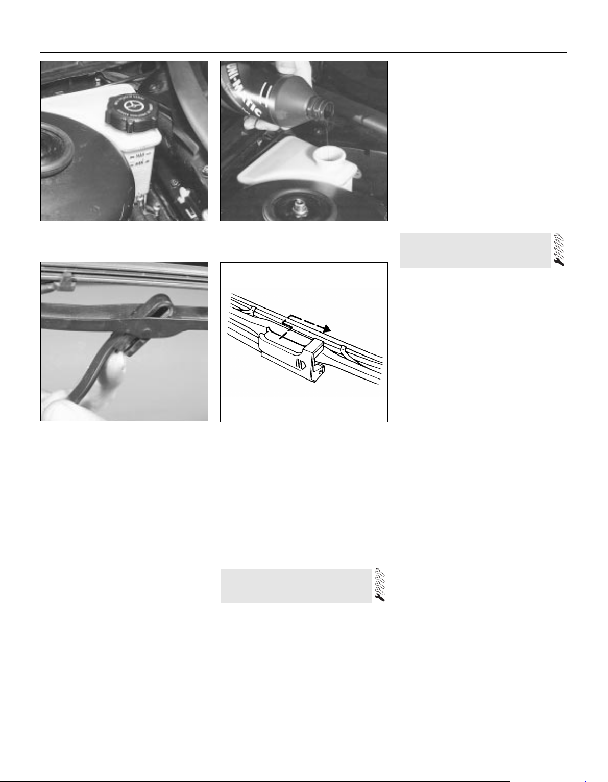
the tyre to cause deflation. If removal of a nail
reveals that the tyre has been punctured, refit
the nail, so that its point of penetration is
marked. Then immediately change the wheel,
and have the tyre repaired by a tyre dealer. Do
not drive on a tyre in such a condition. If in any
doubt as to the possible consequences of any
damage found, consult your local tyre dealer
for advice.
8 General tyre wear is influenced to a large
degree by driving style — harsh braking and
acceleration, or fast cornering, will all produce
more rapid tyre wear. Interchanging of tyres
may result in more even wear; however, it is
worth bearing in mind that if this is completely
effective, the added expense is incurred of
replacing simultaneously a complete set of
tyres, which may prove financially restrictive
for many owners.
9 Front tyres may wear unevenly as a result of
wheel misalignment. The front wheels should
always be correctly aligned according to the
settings specified by the vehicle
manufacturer.
10 Don’t forget to check the spare tyre for
condition and pressure.
11 Legal restrictions apply to many aspects
of tyre fitting and usage, and in the UK this
information is contained in the Motor Vehicle
Construction and Use Regulations. It is
suggested that a copy of these regulations is
obtained from your local police, if in doubt as
to current legal requirements with regard to
tyre type and condition, minimum tread depth,
etc.
1 The power steering fluid reservoir is located
on the right-hand rear corner of the engine
compartment.
2 For the fluid level check, the power steering
system should be at its normal operating
temperature, so it is best to carry out the
check after a run.
3 Position the vehicle on level ground, with
the front wheels pointing straight ahead, and
switch off the engine.
4 Check that the fluid level is up to the “MAX”
mark on the reservoir (see illustration).
5 If topping-up is required, first use a clean
rag to wipe the filler cap and the surrounding
area, to prevent foreign matter from entering
the system. Unscrew and remove the filler
cap.
6 Top-up the level to the “MAX” mark, using
the grade of fluid specified at the beginning of
this Chapter (see illustration). Be careful not
to introduce dirt into the system, and do not
overfill. The need for frequent topping-up
indicates a leak, which should be
investigated.
7 Refit the filler cap.
1 The windscreen wiper and blade assembly
should be inspected at the specified intervals
for damage, loose components, and cracked
or worn blade elements.
2 Road film can build up on the wiper blades
and affect their efficiency, so they should be
washed regularly with a mild detergent
solution.
3 The action of the wiping mechanism can
loosen bolts, nuts and fasteners, so they
should be checked and tightened, as
necessary, at the same time as the wiper
blades are checked.
4 If the wiper blade elements are cracked,
worn or warped, or no longer clean
adequately, they should be replaced with new
ones.
5 Lift the wiper arm and blade away from the
glass.
6 To remove the windscreen wiper blade,
release the catch on the arm, then turn the
blade through 90° and withdraw the blade
from the end of the arm (see illustration).
7 To remove the tailgate wiper blade, push
the wiper blade forward, and at the same time
depress it against the spring pressure, then
withdraw it from the end of the arm (see
illustration).
8 If the metal part of the wiper blade is in
good condition, it may be possible to renew
the rubber insert separately. The insert can be
obtained from a car accessory shop and,
according to type, it may need to be cut to the
correct length before sliding into the clips.
9 Refit the wiper blade assembly using a
reversal of the removal procedure, making
sure that it fully engages with the spring clip.
10 Check that the washer jets direct the fluid
onto the upper part of the
windscreen/tailgate/rear window/headlight,
and if necessary adjust the small sphere on
the jet with a pin.
6 Windscreen/tailgate washer
system and wiper blade check
5 Power steering fluid level
check
1•10
5.4 Power steering fluid reservoir,
showing “MAX” and “MIN” marks
5.6 Topping-up the power steering fluid
reservoir
6.7 Tailgate wiper blade removal
6.6 Releasing the catch to remove a
windscreen wiper blade
Weekly checks
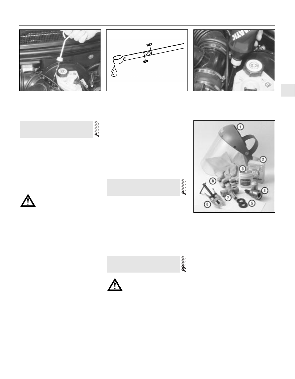
Every 10 000 miles or 12 months
1•11
1
7.4 Removing the automatic transmission
dipstick from its tube
7.6A “MIN” and “MAX” marks on the
dipstick
7.6B Adding automatic transmission fluid
through the dipstick tube
Every 10 000 miles
1 The level of the automatic transmission fluid
should be carefully maintained. Low fluid level
can lead to slipping or loss of drive, while
overfilling can cause foaming, loss of fluid and
transmission damage.
2 The transmission fluid level should only be
checked when the transmission is hot (at its
normal operating temperature). If the vehicle
has just been driven over 10 miles (15 miles in
a cold climate), and the fluid temperature is
160 to 175°F, the transmission is hot.
Caution: If the vehicle has just
been driven for a long time at
high speed or in city traffic in hot
weather, or if it has been pulling
a trailer, an accurate fluid level reading
cannot be obtained. In these
circumstances, allow the fluid to cool
down for about 30 minutes.
3 Park the vehicle on level ground, apply the
handbrake, and start the engine. While the
engine is idling, depress the brake pedal and
move the selector lever through all the gear
ranges three times, beginning and ending in
“P”.
4 Allow the engine to idle for one minute, then
(with the engine still idling) remove the dipstick
from its tube (see illustration). Note the
condition and colour of the fluid on the dipstick.
5 Wipe the fluid from the dipstick with a clean
rag, and re-insert it into the filler tube until the
cap seats.
6 Pull the dipstick out again, and note the
fluid level. The level should be between the
“MIN” and “MAX” marks. If the level is on the
“MIN” mark, stop the engine, and add the
specified automatic transmission fluid through
the dipstick tube, using a clean funnel if
necessary (see illustrations). It is important
not to introduce dirt into the transmission
when topping-up.
7 Add the fluid a little at a time, and keep
checking the level as previously described
until it is correct.
8 The need for regular topping-up of the
transmission fluid indicates a leak, which
should be found and rectified without delay.
9 The condition of the fluid should also be
checked along with the level. If the fluid at the
end of the dipstick is black or a dark reddishbrown colour, or if it has a burned smell, the
fluid should be changed. If you are in doubt
about the condition of the fluid, purchase
some new fluid, and compare the two for
colour and smell.
1 Check the operation of all external lights
and indicators (front and rear).
2 Check for satisfactory operation of the
instrument panel, its illumination and warning
lights, the switches and their function lights.
3 Check the horn(s) for satisfactory operation.
4 Check all other electrical equipment for
satisfactory operation.
5 Check all electrical wiring in the engine
compartment for correct routing, and for any
signs of physical or heat-damage or chafing.
Warning: Certain precautions
must be followed when checking
and servicing the battery.
Hydrogen gas, which is highly
flammable, is always present in the battery
cells, so keep lighted tobacco and all other
open flames and sparks away from the
battery. The electrolyte inside the battery
is actually dilute sulphuric acid, which will
cause injury if splashed on your skin or in
your eyes. It will also ruin clothes and
painted surfaces. When disconnecting the
battery, always detach the negative (earth)
lead first and connect it last!
Note: Before disconnecting the battery, refer
to Section 1 of Chapter 5.
9 Battery check, maintenance
and charging
8 Electrical system check
7 Automatic transmission fluid
level check
9.1 Tools and materials required for
battery maintenance
1 Face shield/safety goggles — When
removing corrosion with a brush, the acidic
particles can easily fly up into your eyes
2 Baking soda — A solution of baking soda
and water can be used to neutralise corrosion
3 Petroleum jelly — A layer of this on the
battery terminals will help prevent corrosion
4 Battery terminal/lead cleaner — This wire
brush cleaning tool will remove all traces of
corrosion from the battery terminals and lead
clamps
5 Treated felt washers — Placing one of
these on each terminal, directly under the
lead clamps, will help prevent corrosion
6 Puller — Sometimes the lead clamps are
very difficult to pull off the terminals, even
after the nut has been completely slackened.
This tool pulls the clamp straight up and off
the terminal without damage
7 Battery terminal/lead cleaner — Here is
another cleaning tool which is a slightly
different version of number 4 above, but does
the same thing
8 Rubber gloves — Another safety item to
consider when servicing the battery;
remember, that’s acid inside the battery!
General
1 A routine preventive maintenance
programme for the battery in your vehicle is
the only way to ensure quick and reliable
starts. Before performing any battery
maintenance, make sure that you have the
proper equipment necessary to work safely
around the battery (see illustration).
2 There are also several precautions that
should be taken whenever battery
maintenance is performed. Before servicing
the battery, always turn the engine and all
accessories off, and disconnect the lead from
the negative terminal of the battery — see
Chapter 5, Section 1.
3 The battery produces hydrogen gas, which
is both flammable and explosive. Never create
a spark, smoke, or light a match around the
battery. Always charge the battery in a wellventilated area.
4 Electrolyte contains poisonous and
corrosive sulphuric acid. Do not allow it to get
in your eyes, on your skin, or on your clothes.
Never ingest it. Wear protective safety glasses
when working near the battery. Keep children
away from the battery.
5 Note the external condition of the battery. If
the positive terminal and lead clamp on your
vehicle’s battery is equipped with a plastic
cover or rubber protector, make sure that it’s
not torn or damaged. It should completely
cover the terminal. Look for any corroded or
loose connections, cracks in the case or
cover, or loose hold-down clamps. Also check
the entire length of each lead for cracks and
frayed conductors.
6 If corrosion, which looks like white, fluffy
deposits (see illustration) is evident,
particularly around the terminals, the battery
should be removed for cleaning. Slacken the
lead clamp nuts with a spanner, being careful
to remove the negative (earth) lead first, and
slide them off the terminals (see illustration).
Then unscrew the hold-down clamp nuts,
remove the clamp, and lift the battery from the
engine compartment.
7 Clean the lead clamps thoroughly, using a
soft wire brush or a terminal cleaner, with a
solution of warm water and baking soda.
Wash the terminals and the top of the battery
case with the same solution, but make sure
that the solution doesn’t get into the battery.
When cleaning the leads, terminals and
battery top, wear safety goggles and rubber
gloves, to prevent any solution from coming in
contact with your eyes or hands. Wear old
clothes too — even when diluted, sulphuric
acid splashed onto clothes will burn holes in
them. If the terminals have been extensively
corroded, clean them up with a terminal
cleaner (see illustrations). Thoroughly wash
all cleaned areas with plain water.
8 Make sure that the battery tray is in good
condition and the hold-down clamp nuts are
tight (see illustration). If the battery is
removed from the tray, make sure no parts
remain in the bottom of the tray when the
battery is refitted. When refitting the
hold-down clamp nuts, do not overtighten
them.
9 Information on removing and installing the
battery can be found in Chapter 5. Information
on jump starting can be found at the front of
this manual. For more detailed battery
checking procedures, refer to the Haynes
Automobile Electrical and Electronic Systems
Manual.
Cleaning
10 Corrosion on the hold-down components,
battery case and surrounding areas can be
removed with a solution of water and baking
soda. Thoroughly rinse all cleaned areas with
plain water.
11 Any metal parts of the vehicle damaged
by corrosion should be covered with a
zinc-based primer, then painted.
Charging
Warning: When batteries are
being charged, hydrogen gas,
which is very explosive and
flammable, is produced. Do not
smoke, or allow open flames, near a
charging or a recently-charged battery.
Wear eye protection when near the battery
during charging. Also, make sure the
charger is unplugged before connecting or
disconnecting the battery from the
charger.
12 Slow-rate charging is the best way to
restore a battery that’s discharged to the
point where it will not start the engine. It’s also
a good way to maintain the battery charge in a
vehicle that’s only driven a few miles between
starts. Maintaining the battery charge is
particularly important in winter, when the
battery must work harder to start the engine,
and electrical accessories that drain the
battery are in greater use.
13 It’s best to use a one- or two-amp battery
charger (sometimes called a “trickle” charger).
They are the safest, and put the least strain on
the battery. They are also the least expensive.
For a faster charge, you can use a higher-
1•12
9.6A Battery terminal corrosion usually
appears as light, fluffy powder
9.6B Removing a lead from the battery
terminal — always remove the earth lead
first, and connect it last!
9.7A When cleaning the lead clamps, all
corrosion must be removed — the inside of
the clamp is tapered to match the terminal,
so don’t remove too much material
9.7B Regardless of the method used to
clean the terminals, a clean, shiny surface
should result
9.8 Make sure the battery hold-down nuts
(arrowed) are tight
Every 10 000 miles
amperage charger, but don’t use one rated
more than 1/10th the amp/hour rating of the
battery (ie no more than 5 amps, typically).
Rapid boost charges that claim to restore the
power of the battery in one to two hours are
hardest on the battery, and can damage
batteries not in good condition. This type of
charging should only be used in emergency
situations.
14 The average time necessary to charge a
battery should be listed in the instructions that
come with the charger. As a general rule, a
trickle charger will charge a battery in 12 to
16 hours.
1 Check the seat belts for satisfactory
operation and condition. Inspect the webbing
for fraying and cuts. Check that they retract
smoothly and without binding into their reels.
2 Check that the seat belt mounting bolts are
tight, and if necessary tighten them to the
specified torque wrench setting.
General
1 The auxiliary drivebelt is of the flat, multiribbed (or “polyvee”) type, and is located on
the right-hand end of the engine. It drives the
alternator, water pump, power steering pump
and (when fitted) the air conditioning
compressor from the engine’s crankshaft
pulley.
2 The good condition and proper tension of
the auxiliary drivebelt is critical to the
operation of the engine. Because of their
composition and the high stresses to which
they are subjected, drivebelts stretch and
deteriorate as they get older. They must,
therefore, be regularly inspected.
Check
3 With the engine switched off, open and
support the bonnet, then locate the auxiliary
drivebelt on the right-hand end of the engine,
under the engine right-hand mounting
bracket. (Be very careful, and wear protective
gloves to minimise the risk of burning your
hands on hot components, if the engine has
recently been running.) For improved access,
jack up the front right-hand side of the
vehicle, support it securely on an axle stand,
remove the roadwheel, then remove the
auxiliary drivebelt cover (two fasteners) from
inside the wheel arch (see illustration).
4 Using an inspection light or a small electric
torch, and rotating the engine when necessary
with a spanner applied to the crankshaft
pulley bolt, check the whole length of the
drivebelt for cracks, separation of the rubber,
and torn or worn ribs (see illustration). Also
check for fraying and glazing, which gives the
drivebelt a shiny appearance. Both sides of
the drivebelt should be inspected, which
means you will have to twist the drivebelt to
check the underside. Use your fingers to feel
the drivebelt where you can’t see it. If you are
in any doubt as to the condition of the
drivebelt, renew it (go to paragraph 7).
Drivebelt tension
5 The auxiliary drivebelt is tensioned by an
automatic tensioner; regular checks are not
required, and manual “adjustment” is not
possible.
6 If you suspect that the drivebelt is slipping
and/or running slack, or that the tensioner is
otherwise faulty, it must be renewed. To do
this, remove the drivebelt as described below,
then unbolt the tensioner (two Torx-type
screws accessible from underneath, via the
wheel arch) from the alternator mounting
bracket (see illustration). On fitting the new
tensioner, ensure it is aligned correctly on its
mountings, and tighten the screws to the
specified torque wrench setting.
Renewal
7 Open the bonnet. Jack up the front righthand side of the vehicle and support it
securely on an axle stand, remove the
roadwheel, then remove the auxiliary drivebelt
cover (two fasteners) from inside the wheel
arch.
8 If the existing drivebelt is to be refitted,
mark it, or note the maker’s markings on its
flat surface, so that it can be installed the
same way round.
9 Reaching up between the body and the
engine (above and to the rear of the
crankshaft pulley), apply a spanner to the
hexagon in the centre of the automatic
tensioner’s pulley. Rotate the tensioner pulley
clockwise to release its pressure on the
drivebelt, then slip the drivebelt off the
crankshaft pulley, and release the tensioner
again (see illustration). Working from the
wheel arch or engine compartment as
necessary, and noting its routing, slip the
drivebelt off the remaining pulleys and
withdraw it.
10 Check all the pulleys, ensuring that their
grooves are clean, and removing all traces of
oil and grease. Check that the tensioner
works properly, with strong spring pressure
11 Auxiliary drivebelt check and
renewal
10 Seat belt check
1•13
1
11.9 Rotate the tensioner pulley clockwise
to release its pressure on the drivebelt,
then slip the drivebelt off the crankshaft
pulley
11.3 Removing the auxiliary drivebelt
cover — it is secured by a fastener at each
end (arrowed) — from inside the right-hand
front wheel arch
11.4 Check the auxiliary drivebelt for signs
of wear like these. Very small cracks across
the drivebelt ribs are acceptable. If the
cracks are deep, or if the drivebelt looks
worn or damaged in any other way, renew it
11.6 The auxiliary drivebelt is tensioned by
an automatic tensioner; Torx screws
(arrowed) secure it to alternator mounting
bracket
Every 10 000 miles
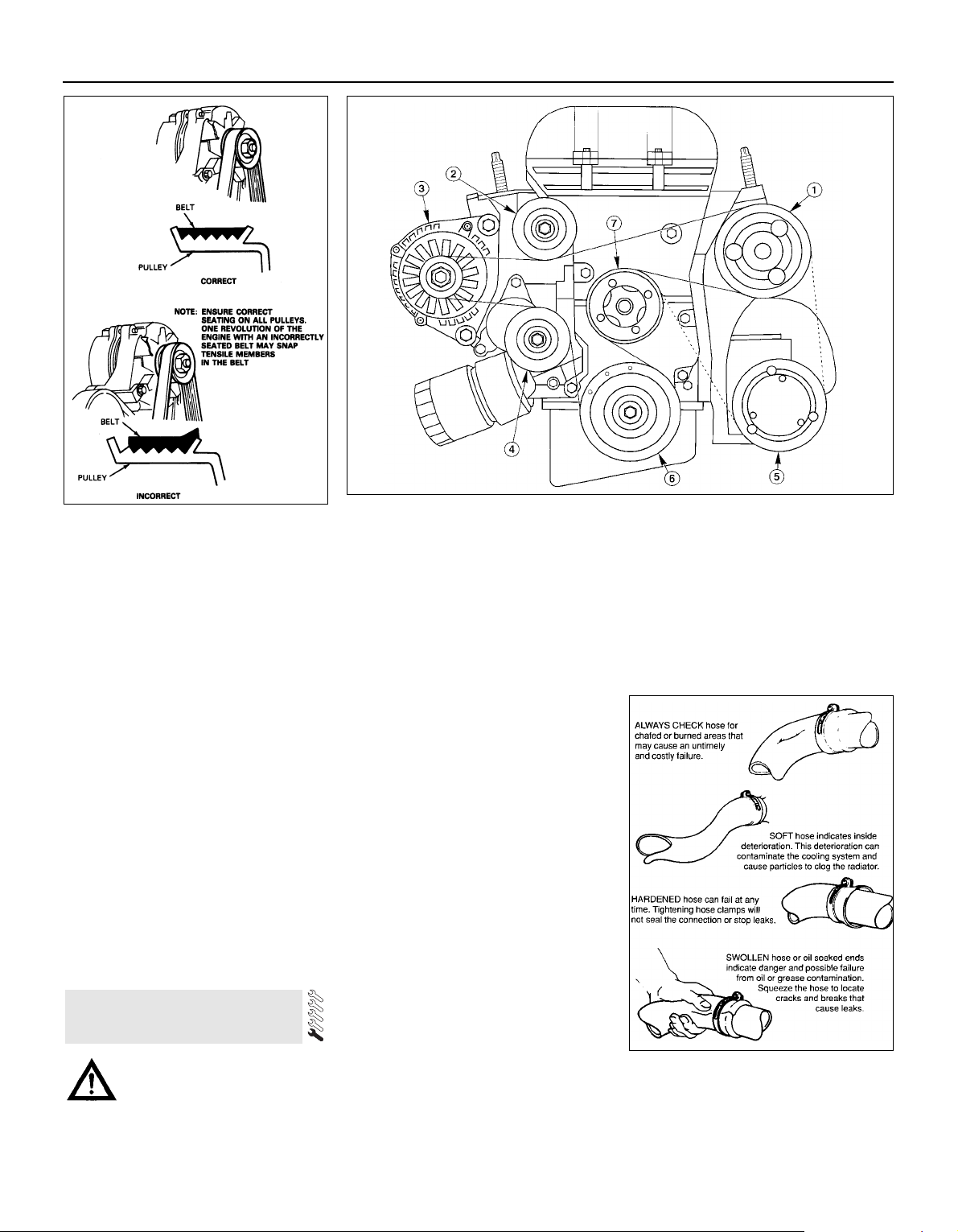
being felt when its pulley is rotated clockwise,
and a smooth return to the limit of its travel
when released.
11 If the original drivebelt is being refitted,
use the marks or notes made on removal, to
ensure that it is installed to run in the same
direction as it was previously. To fit the
drivebelt, arrange it on the grooved pulleys so
that it is centred in their grooves, and not
overlapping their raised sides (note that the
flat surface of the drivebelt is engaged on the
idler, tensioner and water pump pulleys) and
routed correctly (see illustrations). Start at
the top, and work down to finish at the
crankshaft pulley; rotate the tensioner pulley
clockwise, slip the drivebelt onto the
crankshaft pulley, then release the tensioner
again.
12 Using a spanner applied to the crankshaft
pulley bolt, rotate the crankshaft through at
least two full turns clockwise to settle the
drivebelt on the pulleys, then check that the
drivebelt is properly installed.
13 Refit the auxiliary drivebelt cover and
roadwheel, then lower the vehicle to the
ground.
Caution: Renewal of air
conditioning hoses must be left
to a dealer service department or
air conditioning specialist who has the
equipment to depressurise the system
safely. Never remove air conditioning
components or hoses until the system has
been depressurised.
General
1 High temperatures in the engine
compartment can cause the deterioration of
the rubber and plastic hoses used for engine,
accessory and emission systems operation.
Periodic inspection should be made for
cracks, loose clamps, material hardening and
leaks.
2 Carefully check the large top and bottom
radiator hoses, along with the other smallerdiameter cooling system hoses and metal
pipes; do not forget the heater hoses/pipes
which run from the engine to the bulkhead,
and those to the engine oil cooler (where
fitted). Inspect each hose along its entire
length, replacing any that is cracked, swollen
or shows signs of deterioration. Cracks may
become more apparent if the hose is
squeezed (see illustration). If you are using
non-Ford specification antifreeze, and so
have to renew the coolant every two years or
so, it’s a good idea to renew the hoses at that
time, regardless of their apparent condition.
3 Make sure that all hose connections are
tight. A leak in the cooling system will usually
show up as white- or rust-coloured deposits
on the areas adjoining the leak; if the spring
clamps that are used to secure the hoses in
this system appear to be slackening, they
should be renewed to prevent the possibility
of leaks.
4 Some other hoses are secured to their
fittings with clamps. Where clamps are used,
check to be sure they haven’t lost their
tension, allowing the hose to leak. If clamps
aren’t used, make sure the hose has not
expanded and/or hardened where it slips over
the fitting, allowing it to leak.
12 Underbonnet check for fluid
leaks and hose condition
1•14
11.11A When installing the auxiliary
drivebelt, make sure that it is centred — it
must not overlap either edge of the
grooved pulleys
11.11B Auxiliary drivebelt routing
1 Power steering pump
2 Idler pulley
3 Alternator
4 Automatic tensioner
5 Air conditioning
compressor (when fitted)
6 Crankshaft pulley
7 Water pump pulley
12.2 Hoses, like drivebelts, have a habit of
failing at the worst possible time — to
prevent the inconvenience of a blown
radiator or heater hose, inspect them
carefully as shown here
Every 10 000 miles
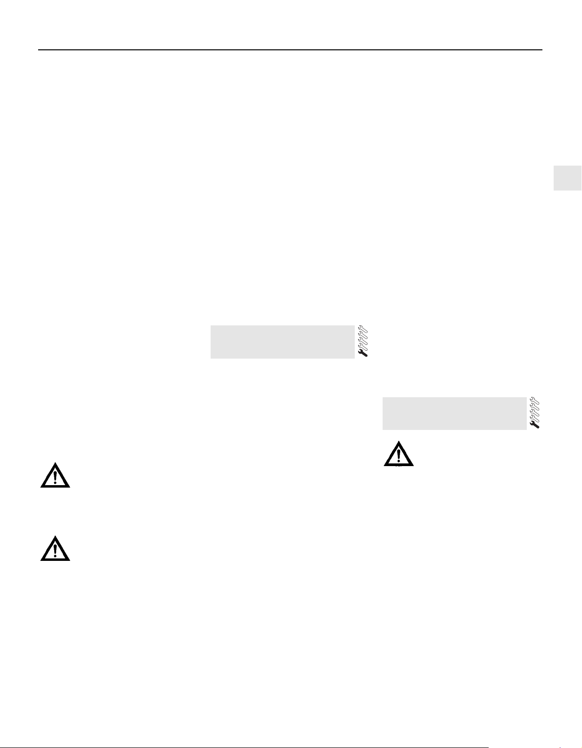
5 Check all fluid reservoirs, filler caps, drain
plugs and fittings etc, looking for any signs of
leakage of oil, transmission and/or brake
hydraulic fluid, coolant and power steering
fluid. If the vehicle is regularly parked in the
same place, close inspection of the ground
underneath it will soon show any leaks; ignore
the puddle of water which will be left if the air
conditioning system is in use. As soon as a
leak is detected, its source must be traced
and rectified. Where oil has been leaking for
some time, it is usually necessary to use a
steam cleaner, pressure washer or similar, to
clean away the accumulated dirt, so that the
exact source of the leak can be identified.
Vacuum hoses
6 It’s quite common for vacuum hoses,
especially those in the emissions system, to
be colour-coded, or to be identified by
coloured stripes moulded into them. Various
systems require hoses with different wall
thicknesses, collapse resistance and
temperature resistance. When renewing
hoses, be sure the new ones are made of the
same material.
7 Often the only effective way to check a
hose is to remove it completely from the
vehicle. If more than one hose is removed, be
sure to label the hoses and fittings to ensure
correct installation.
8 When checking vacuum hoses, be sure to
include any plastic T-fittings in the check.
Inspect the fittings for cracks, and check the
hose where it fits over the fitting for distortion,
which could cause leakage.
9 A small piece of vacuum hose (quarter-inch
inside diameter) can be used as a
stethoscope to detect vacuum leaks. Hold
one end of the hose to your ear, and probe
around vacuum hoses and fittings, listening
for the “hissing” sound characteristic of a
vacuum leak.
Warning: When probing with the
vacuum hose stethoscope, be
very careful not to come into
contact with moving engine
components such as the auxiliary
drivebelt, radiator electric cooling fan, etc.
Fuel hoses
Warning: There are certain
precautions which must be taken
when inspecting or servicing fuel
system components. Work in a wellventilated area, and do not allow open
flames (cigarettes, appliance pilot lights,
etc.) or bare light bulbs near the work
area. Mop up any spills immediately, and
do not store fuel-soaked rags where they
could ignite.
10 Check all fuel hoses for deterioration and
chafing. Check especially for cracks in areas
where the hose bends, and also just before
fittings, such as where a hose attaches to the
fuel filter.
11 High-quality fuel line, usually identified by
the word “Fluoroelastomer” printed on the
hose, should be used for fuel line renewal.
Never, under any circumstances, use
unreinforced vacuum line, clear plastic tubing
or water hose for fuel lines.
12 Spring-type clamps are commonly used
on fuel lines. These clamps often lose their
tension over a period of time, and can be
“sprung” during removal. Replace all
spring-type clamps with screw clamps
whenever a hose is replaced.
Metal lines
13 Sections of metal piping are often used
for fuel line between the fuel filter and the
engine. Check carefully to be sure the piping
has not been bent or crimped, and that cracks
have not started in the line.
14 If a section of metal fuel line must be
renewed, only seamless steel piping should
be used, since copper and aluminium piping
don’t have the strength necessary to
withstand normal engine vibration.
15 Check the metal brake lines where they
enter the master cylinder and ABS hydraulic
unit (if used) for cracks in the lines or loose
fittings. Any sign of brake fluid leakage calls
for an immediate and thorough inspection of
the brake system.
1 With the vehicle parked on level ground,
apply the handbrake firmly and open the
bonnet. Using an inspection light or a small
electric torch, check all visible wiring within
and beneath the engine compartment.
2 What you are looking for is wiring that is
obviously damaged by chafing against sharp
edges, or against moving suspension/
transmission components and/or the auxiliary
drivebelt, by being trapped or crushed
between carelessly-refitted components, or
melted by being forced into contact with the
hot engine castings, coolant pipes, etc. In
almost all cases, damage of this sort is
caused in the first instance by incorrect
routing on reassembly after previous work has
been carried out.
3 Depending on the extent of the problem,
damaged wiring may be repaired by rejoining
the break or splicing-in a new length of wire,
using solder to ensure a good connection,
and remaking the insulation with adhesive
insulating tape or heat-shrink tubing, as
appropriate. If the damage is extensive, given
the implications for the vehicle’s future
reliability, the best long-term answer may well
be to renew that entire section of the loom,
however expensive this may appear.
4 When the actual damage has been
repaired, ensure that the wiring loom is rerouted correctly, so that it is clear of other
components, and not stretched or kinked, and
is secured out of harm’s way using the plastic
clips, guides and ties provided.
5 Check all electrical connectors, ensuring
that they are clean, securely fastened, and
that each is locked by its plastic tabs or wire
clip, as appropriate. If any connector shows
external signs of corrosion (accumulations of
white or green deposits, or streaks of “rust”),
or if any is thought to be dirty, it must be
unplugged and cleaned using electrical
contact cleaner. If the connector pins are
severely corroded, the connector must be
renewed; note that this may mean the renewal
of that entire section of the loom — see your
local Ford dealer for details.
6 If the cleaner completely removes the
corrosion to leave the connector in a
satisfactory condition, it would be wise to
pack the connector with a suitable material
which will exclude dirt and moisture,
preventing the corrosion from occurring
again; a Ford dealer may be able to
recommend a suitable product.
7 Check the condition of the battery
connections — remake the connections or
renew the leads if a fault is found (see Chapter 5). Use the same techniques to ensure that
all earth points in the engine compartment
provide good electrical contact through clean,
metal-to-metal joints, and that all are securely
fastened. (In addition to the earth connection
at the engine lifting eye, and that from the
transmission to the body/battery, there are
one or two earth points behind each headlight
assembly, and one below the power steering
fluid reservoir.)
8 Refer to Section 31 for details of spark plug
(HT) lead checks.
Warning: The air conditioning
system is under high pressure.
Do not loosen any fittings or
remove any components until
after the system has been discharged. Air
conditioning refrigerant must be properly
discharged into an approved type of
container, at a dealer service department
or an automotive air conditioning repair
facility capable of handling R134a
refrigerant. Always wear eye protection
when disconnecting air conditioning
system fittings.
1 The following maintenance checks should
be performed on a regular basis, to ensure
that the air conditioner continues to operate at
peak efficiency:
(a) Check the auxiliary drivebelt. If it’s worn
or deteriorated, renew it (see Section 11).
(b) Check the system hoses. Look for cracks,
bubbles, hard spots and deterioration.
Inspect the hoses and all fittings for oil
bubbles and seepage. If there’s any
evidence of wear, damage or leaks, renew
the hose(s).
(c) Inspect the condenser fins for leaves,
insects and other debris. Use a “fin
14 Air conditioning system
check
13 Engine compartment wiring
check
1•15
1
Every 10 000 miles

comb” or compressed air to clean the
condenser.
Warning: Wear eye protection
when using compressed air!
(d) Check that the drain tube from the front
of the evaporator is clear — note that it is
normal to have clear fluid (water) dripping
from this while the system is in operation,
to the extent that quite a large puddle can
be left under the vehicle when it is parked.
2 It’s a good idea to operate the system for
about 30 minutes at least once a month,
particularly during the winter. Long term
non-use can cause hardening, and
subsequent failure, of the seals.
3 Because of the complexity of the air
conditioning system and the special
equipment necessary to service it, in-depth
fault diagnosis and repairs are not included in
this manual. For more complete information
on the air conditioning system, refer to the
Haynes Automotive Heating and Air
Conditioning Manual.
4 The most common cause of poor cooling is
simply a low system refrigerant charge. If a
noticeable drop in cool air output occurs, the
following quick check will help you determine
if the refrigerant level is low.
5 Warm the engine up to normal operating
temperature.
6 Place the air conditioning temperature
selector at the coldest setting, and put the
blower at the highest setting. Open the doors
— to make sure the air conditioning system
doesn’t cycle off as soon as it cools the
passenger compartment.
7 With the compressor engaged — the clutch
will make an audible click, and the centre of
the clutch will rotate — feel the inlet and outlet
pipes at the compressor. One side should be
cold, and one hot. If there’s no perceptible
difference between the two pipes, there’s
something wrong with the compressor or the
system. It might be a low charge — it might be
something else. Take the vehicle to a dealer
service department or an automotive air
conditioning specialist.
1 Make sure that you have all the necessary
tools before you begin this procedure (see
illustration). You should also have plenty of
rags or newspapers handy, for mopping up
any spills.
2 To avoid any possibility of scalding, and to
protect yourself from possible skin irritants
and other harmful contaminants in used
engine oils, it is advisable to wear gloves
when carrying out this work.
3 Access to the underside of the vehicle is
greatly improved if the vehicle can be lifted on
a hoist, driven onto ramps, or supported by
axle stands.
Warning: Do not work under a
vehicle which is supported only
by an hydraulic or scissors-type
jack, or by bricks, blocks of
wood, etc.
4 If this is your first oil change, get under the
vehicle and familiarise yourself with the
position of the engine oil drain plug, which is
located at the rear of the sump. The engine
and exhaust components will be warm during
the actual work, so try to anticipate any
potential problems while the engine and
accessories are cool.
5 The oil should preferably be changed when
the engine is still fully warmed-up to normal
operating temperature, just after a run (the
needle on the temperature gauge should be in
the “Normal” sector of the gauge); warm oil
and sludge will flow out more easily. Park the
vehicle on firm, level ground, apply the
handbrake firmly, then select 1st or reverse
gear (manual transmission) or the “P” position
(automatic transmission). Open the bonnet
and remove the engine oil filler cap from the
cylinder head cover, then remove the oil level
dipstick from its tube (see Section 3).
6 Raise the front of the vehicle, and support it
securely on axle stands. Remove the front
right-hand roadwheel to provide access to the
oil filter; if the additional working clearance is
required, remove also the auxiliary drivebelt
cover (two fasteners).
15 Engine oil and filter change
1•16
15.1 These tools are required when
changing the engine oil and filter
1 Drain pan — It should be fairly shallow in
depth, but wide to prevent spills
2 Rubber gloves — When removing the drain
plug and filter, it is inevitable that you will get
oil on your hands (the gloves will prevent
burns from hot oil)
3 Breaker bar — Sometimes the oil drain plug
is pretty tight, and a long breaker bar is
needed to loosen it
4 Socket — To be used with the breaker bar
or a ratchet (must be the correct size to fit the
drain plug)
5 Filter wrench — This is a metal band-type
wrench, which requires clearance around the
filter to be effective
6 Filter wrench — This type fits on the
bottom of the filter, and can be turned with a
ratchet or breaker bar (different size wrenches
are available for different types of filters)
15.7 Use the correct-size spanner or
socket to remove the oil drain plug and
avoid rounding it off
15.9 Since the oil filter is usually on very
tight, you’ll need a special wrench for
removal. DO NOT use the wrench to
tighten the new filter. Pack rag under the
filter before removal to minimise the mess
Every 10 000 miles
Frequent oil changes are the
best preventive maintenance
the home mechanic can give
the engine, because ageing
oil becomes diluted and contaminated,
which leads to premature engine wear.
Note: It is
antisocial and
illegal to dump
oil down the
drain. To find
the location of
your local oil
recycling bank,
call this
number free.
Loading…
Руководство на английском языке по техническому обслуживанию и ремонту Ford Mondeo 1993-2000 года выпуска с бензиновыми двигателями.
- Автор: J. Churchill, A.K. Legg
- Издательство: Haynes Publishing
- Год издания: 1996
- Страниц: 279
- Формат: PDF
- Размер: 12,5 Mb
Руководство по эксплуатации и ремонту Ford Mondeo с 2007 года выпуска с бензиновыми и дизельными двигателями.
- Автор: коллектив авторов
- Издательство: ИДТР
- Год издания: 2010
- Страниц: 353
- Формат: PDF
- Размер: 264,7 Mb
Руководство по техническому обслуживанию и ремонту Ford Mondeo 1993-1999 годов выпуска с бензиновыми двигателями.
- Автор: —
- Издательство: Алфамер
- Год издания: —
- Страниц: 393
- Формат: PDF
- Размер: 89,7Мб
Руководство по техническому обслуживанию и ремонту Ford Mondeo 2000-2003 годов выпуска с бензиновыми и дизельными двигателями.
- Автор: —
- Издательство: Алфамер
- Год издания: —
- Страниц: 472
- Формат: —
- Размер: —
Руководство для станций технического обслуживания по ремонту и обслуживанию Ford Mondeo 2002 года выпуска.
- Автор: —
- Издательство: Ford Motor Company
- Год издания: 2001
- Страниц: 2479
- Формат: PDF
- Размер: 67,4 Mb
Руководство по эксплуатации, техническому обслуживанию и ремонту + каталог расходных запчастей автомобиля Ford Mondeo 2003-2007 годов выпуска с бензиновыми и дизельными двигателями.
- Автор: —
- Издательство: Легион-Автодата
- Год издания: —
- Страниц: 470
- Формат: —
- Размер: —
Руководство по эксплуатации и ремонту Ford Mondeo 1993-2000 годов выпуска с бензиновыми и дизельными двигателями.
- Автор: —
- Издательство: Чижовка
- Год издания: 1996
- Страниц: 296
- Формат: PDF
- Размер: —
Руководство по техническому обслуживанию и ремонту Ford Mondeo с 2000 года выпуска с бензиновыми и дизельными двигателями.
- Автор: Дитер Корп, Фридрих Шредер
- Издательство: АСТ
- Год издания: 2005
- Страниц: 306
- Формат: DjVu
- Размер: 47,1 Mb
Руководство по эксплуатации Ford Mondeo 1993 года выпуска.
- Автор: —
- Издательство: Ford Motor Company
- Год издания: —
- Страниц: 140
- Формат: PDF
- Размер: 31,7 Mb
Руководство по эксплуатации Ford Mondeo 2002 года выпуска.
- Автор: —
- Издательство: Ford Motor Company
- Год издания: 2002
- Страниц: 267
- Формат: PDF
- Размер: 3,9 Mb
Руководство по эксплуатации, техническому обслуживанию и ремонту Ford Mondeo 2000-2007 годов выпуска с бензиновыми и дизельными двигателями.
- Автор: —
- Издательство: Арго-Авто
- Год издания: —
- Страниц: 504
- Формат: —
- Размер: —
Руководство по эксплуатации, техническому обслуживанию и ремонту Ford Mondeo с 2007 года выпуска с бензиновыми и дизельными двигателями.
- Автор: —
- Издательство: Арго-Авто
- Год издания: —
- Страниц: 552
- Формат: —
- Размер: —
Подборка руководств по эксплуатации Ford Mondeo 2007-2014 годов выпуска.
- Автор: —
- Издательство: Ford Motor Company
- Год издания: 2007-2014
- Страниц: —
- Формат: PDF
- Размер: 133,9 Mb
Мультимедийное руководство по техническому обслуживанию и ремонту Ford Mondeo с 2000 года выпуска.
- Автор: —
- Издательство: —
- Год издания: —
- Страниц: —
- Формат: ISO
- Размер: 76,7 Mb
Руководство по эксплуатации, техническому обслуживанию и ремонту автомобиля Ford Mondeo с 2007 года выпуска с бензиновыми и дизельными двигателями.
- Автор: —
- Издательство: Третий Рим
- Год издания: —
- Страниц: 352
- Формат: —
- Размер: —
Модели Ford Mondeo новой серии с новыми 16-клапанными двигателями (16V) и впервые установленными двигателями V6 объемом 2,5 л отличаются от прежних моделей следующими свойствами:
1. Общие сведения
1.0 Общие сведения
1.1 Описание автомобилей
1.2 Идентификация автомобиля
1.3 Общие указания по ремонту
1.4 Условия работы и инструмент
1.5 Подъем автомобиля
1.6. Обслуживание и уход за автомобилем
1.7 Смазочные материалы, герметики
1.8 Рекомендации по работе с резьбовыми соединениями
1.9 Аккумуляторная батарея
1.10. Системы подушек безопасности и натяжения ремней безопасности
…
2. Снятие двигателя
2.0 Снятие двигателя
2.1 Установка двигателя
2.2 Разборка двигателя
2.3 Сборка двигателя
2.4. Головка блока цилиндров и клапаны
2.5. Поршни и шатуны
2.6 Блок цилиндров
2.7. Коленчатый вал
2.8. Распределительные валы и механизм газораспределения
2.9 Проверка компрессии в цилиндрах
2.11. Работы на установленном на автомобиле двигателе (выпуска до мая 1998 г.)
2.12. Работы на установленном двигателе (выпуска до мая 1998 г.)
…
3. Система смазки (16-клапанные двигатели)
3.0 Система смазки (16-клапанные двигатели)
3.1. Общие сведения
3.2. Проверка уровня масла в двигателе
3.3 Замена масла
3.4 Замена масляного насоса
3.5 Замена масляного фильтра
3.6 Проверка давления масла
3.7 Замена масляного поддона
3.8 Утечки масла
3.9 Неисправности системы смазки
…
4. Система охлаждения
4.0 Система охлаждения
4.1 Общие сведения
4.2 Замена охлаждающей жидкости
4.3 Замена вентилятора охлаждения радиатора
4.4. Замена радиатора
4.5 Замена жидкостного насоса
4.6. Замена термостата
4.7 Проверка системы охлаждения
4.8 Шланги системы охлаждения
…
5. Системы питания и выпуска отработавших газов
5.0 Системы питания и выпуска отработавших газов
5.1 Общие сведения
5.2 Меры предосторожности при работе с системой питания
5.3 Замена воздушного фильтра
5.4 Замена топливного фильтра
5.5 Проверка работы топливного насоса
5.6 Замена топливного насоса
5.7 Регулировка тросика дроссельной заслонки
5.8. Система впрыска
…
7. Система зажигания
7.0 Система зажигания
7.1 Меры предосторожности при работе с системой зажигания
7.2 Замена блока управления двигателя
7.3 Свечи зажигания
7.4 Диагностика системы зажигания
…
8. Сцепление
8.0 Сцепление
8.1 Проверка сцепления
8.2. Замена сцепления
8.3. Гидропривод сцепления
8.4 Регулировка свободного хода педали сцепления
…
9. Механическая коробка передач
9.0 Механическая коробка передач
9.1 Снятие и установка коробки передач
9.2 Проверка уровня масла в коробке передач
9.3 Неисправности коробки передач
…
11. Привод колес
11.0 Привод колес
11.1 Общие сведения
11.2 Проверка технического состояния валов привода колес
11.3 Меры предосторожности при работе с валами привода колес
11.4. Снятие и установка валов привода колес
11.5 Ремонт привода колес
11.6 Замена упорных подшипников
11.7 Внутренние радиальные уплотнительные кольца
…
12. Передняя подвеска
12.0 Передняя подвеска
12.1 Общие сведения
12.2. Снятие и установка ступицы переднего колеса и колесного подшипника
12.3. Снятие и установка поворотного кулака
12.4 Снятие и установка левого поперечного рычага подвески
12.5 Снятие и установка правого поперечного рычага
12.6 Снятие и установка стабилизатора поперечной устойчивости
12.7 Снятие и установка подрамника
12.8. Амортизаторная стойка
12.9. Углы установки передних колес
…
13. Задняя подвеска
13.0 Задняя подвеска
13.1. Задняя подвеска (кузов седан)
13.2. Задняя подвеска
13.3 Снятие и установка ступиц задних колес
13.4 Регулировка углов установки задних колес
…
14. Рулевое управление
14.0 Рулевое управление
14.1 Снятие и установка рулевого механизма
14.2. Манжеты рулевого механизма и наконечники поперечных рулевых тяг
14.3 Замена муфты рулевого механизма
14.4 Прокачка привода гидроусилителя рулевого управления
14.5 Замена насоса гидроусилителя рулевого управления
14.6. Рулевое колесо и рулевая колонка
14.7 Радиатор системы охлаждения
…
15. Тормозная система
15.0 Тормозная система
15.1 Конструкция тормозов
15.2 Общее описание
15.3. Техническое обслуживание тормозной системы
15.4. Тормозные механизмы передних колес
15.5. Барабанный тормозной механизм задних колес
15.6. Дисковый тормозной механизм задних колес
15.7. Главный тормозной цилиндр
15.8 Прокачка тормозной системы
15.9 Усилитель тормозов
15.10. Антиблокировочная система (ABS)
15.11. Стояночный тормоз
15.12. Противобуксовочная система
…
16. Электрооборудование
16.0 Электрооборудование
16.1. Аккумуляторная батарея
16.2. Генератор
16.3. Стартер
16.4. Стеклоочиститель
16.5. Наружное освещение
16.6 Ремень привода генератора
16.7 Контрольно-измерительные приборы
…
17. Колеса и диски
17.0 Колеса и диски
17.1 Общее описание
17.2 Виды колесных дисков
17.3 Колесные диски
17.4 Шины
17.5 Замена колес
17.6 Зимние шины
17.7 Проверка давления в шинах
17.8 Увеличение срока службы шин
17.9 Замена колеса
17.10. Проверка состояния шин
…
21. Схемы электрооборудования
21.0 Схемы электрооборудования
21.1 Условные обозначения к электрическим схемам
21.2 Cхемы 1-10
21.3 Схемы 11-20
21.4 Схемы 21-30
21.5 Схемы 31-40
21.6 Схемы 41-47
…