
-
Page 1: Icom IC-R8500
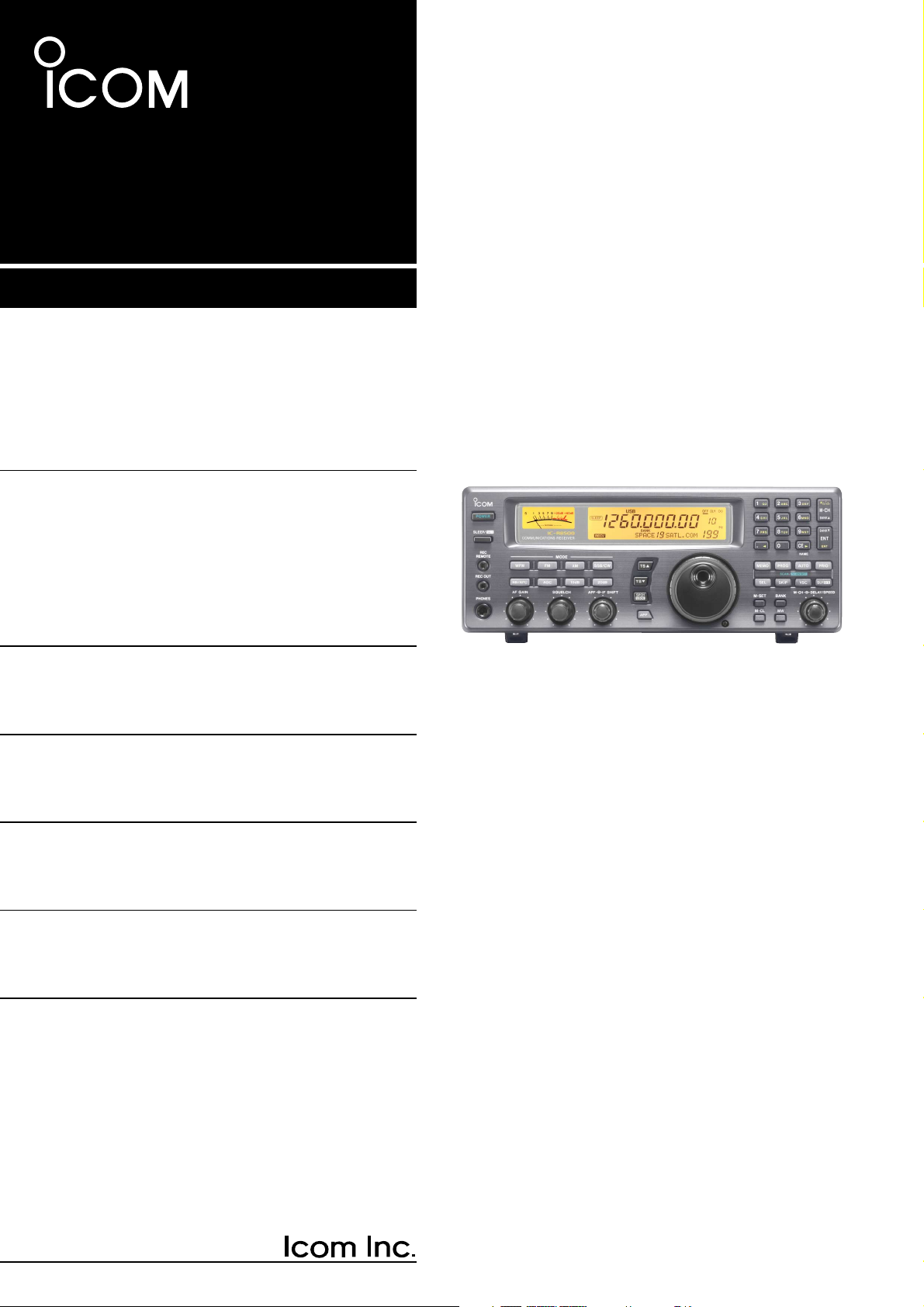
iC- r8500 COMMUNICA TIONS RECEIVER INSTRUCTION MANUAL[…]
-
Page 2: Icom IC-R8500
V ersions of the IC-R8500 which display the “CE” symbol on the serial number seal, comply with the essential requirements of the European Radio and T elecommunication T erminal Directive 1999/5/EC, and that any applicable Essential T est Suite measurements have been performed. UNP ACKING PRECAUTIONS IMPOR T ANT READ THIS INSTRUCTION MANUAL CARE[…]
-
Page 3: Icom IC-R8500
T ABLE OF CONTENTS IMPORT ANT ……………………………………………………. i EXPLICIT DEFINITIONS …………………………………… i PRECAUTIONS ……………………………………………….. i UNP ACKING ……………………………………………………. i T ABLE OF CONTENTS …………………….[…]
-
Page 4: Icom IC-R8500
q POWER SWITCH [POWER] T urns power ON and OFF . w SLEEP/SET SWITCH [SLEEP/SET] ➥ Push momentarily to set the sleep timer (p. 29). • Selectable times are 30, 60, 90, 120 min. or OFF . • “ ” appears in the function display when the sleep timer is set. ➥ Push for 1 sec. to enter quick set mode (p. 30). • Use the [M-CH] selector and main[…]
-
Page 5: Icom IC-R8500
2 1 P ANEL DESCRIPTION !2 AUDIO PEAK FIL TER CONTROL [APF] (p. 15) Adjusts the audio peak fi lter setting to pick up a de- sired audio frequency . Only valid when the [APF] switch is ON. • Clockwise rotation adjusts the fi lter setting higher; coun- terclockwise rotation adjusts the fi lter setting lower . !3 A TTENUA TOR SWITCHES [10dB]/[20dB[…]
-
Page 6: Icom IC-R8500
@1 MEMOR Y SET SWITCH [M-SET] (p. 19) Used to ‘ copy and paste ’ the displayed frequency into another memory channel. • The fi rst push is used to copy ( appears), and the sec- ond push is used to paste ( disappears). • Frequency , mode, tuning step, memory name, etc. can be programmed into a temporary memory . @2 MEMOR Y CLEAR SWITCH [M-C[…]
-
Page 7: Icom IC-R8500
4 1 P ANEL DESCRIPTION [SKIP] (p. 25) ➥ Push momentarily to toggle the skip function ON and OFF for any scan. • Automatic skip activation is available with the [MEMO] switch. ➥ Push for 1 sec. to set the memory channel as a skip channel. [AUTO] (p. 24) ➥ Push momentarily to start/stop auto write scan. ➥ Push for 1 sec. to select the writt[…]
-
Page 8: Icom IC-R8500
5 1 P ANEL DESCRIPTION ■ Rear panel q RS-232C CONNECTOR (p. 10) Connects an RS-232C cable. An RS-232C cable can be used to connect the IC-R8500 to a PC. In this way commands can be sent to the receiver via the PC. w CI-V REMOTE CONTROL JACK (p. 10) Allows connection to an Icom CI-V system trans- ceiver or another receiver for the transceive funct[…]
-
Page 9: Icom IC-R8500
6 1 P ANEL DESCRIPTION ■ Function display q REMOTE INDICA TOR (p. 35) Appears when a level control command is received from a PC via CI-V data. • When this indicator appears, the control knob ’ s setting is ignored. • This indicator will disappear when the control knob is rotated. w MODE INDICA TORS (p. 13) Show the operating mode. e FREQUE[…]
-
Page 10: Icom IC-R8500
7 2 CONNECTIONS ■ Mounting installation D Location Select a location for the receiver that allows adequate air circulation and access to the front and rear panels. Do not place in areas subject to extreme heat, cold, or vibrations, or near TV sets, radios and electromagnetic sources. Be careful of the internal temperature of the receiver . Instal[…]
-
Page 11: Icom IC-R8500
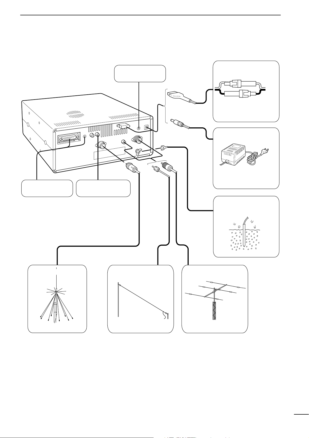
8 2 CONNECTIONS ■ Required connections IC-R8500 Supplied DC power cable Unplug the jumper plug from the [DC13.8V] jack. AC adapter AD-55/A/V Connect either power source The jumper plug must be connected to the [DC 13.8V] jack. Ground connection (p. 9) HF antenna Long wire antenna VHF/UHF wide band antenna Computer control (p. 10) External speaker[…]
-
Page 12: Icom IC-R8500
9 2 CONNECTIONS ■ Antenna connection Antennas play a very important role in receiver opera- tion. Connecting a poor quality antenna to the IC-R8500 will result in less than optimum performance. The IC-R8500 requires at least 2 antennas for full fre- quency coverage: one for 0.1 to 30 MHz and one for 30 to 2000 MHz. D Using a long wire antenna for[…]
-
Page 13: Icom IC-R8500
10 2 CONNECTIONS ■ T ape recorder connections The [REC OUT] jack has 350 mV rms/4.7 k Ω output for connection to other audio equipment. ■ T ransceive function Icom CI-V transceivers or receivers can be connect- ed via the [REMOTE] jack. The frequency and mode become the same* when either radio is changed. * When a set frequency is out-of-rang[…]
-
Page 14: Icom IC-R8500
11 3 FREQUENCY SETTING ■ Read me fi rst The IC-R8500 uses memory channels for storage of frequencies (as well as mode, tuning steps, etc.). When turning power OFF or changing memory chan- nels, the previously displayed frequency cannot be recalled unless it has been stored into a memory channel. Therefore, when you want to keep a dis- played fre[…]
-
Page 15: Icom IC-R8500
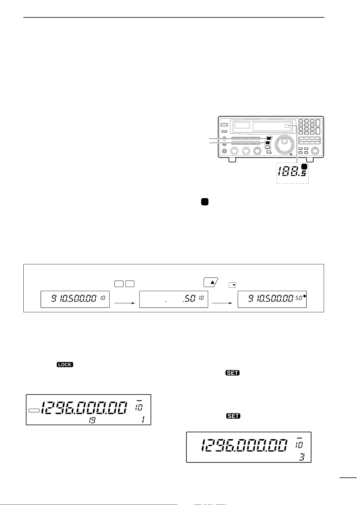
12 3 FREQUENCY SETTING ■ Using the main dial Rotate the main dial to change the frequency . • The frequency changes in increments determined by the selected tuning step (see below). • When the lock function is activated ( “ LOCK ” appears) the frequency cannot be changed. D Selecting a tuning step 13 preset tuning steps are available plus[…]
-
Page 16: Icom IC-R8500
13 4 RECEIVE FUNCTIONS ■ Initial settings ■ Mode selection Push one of the mode keys one or more times to select the desired mode. Consult the table below for basic characteristics of each mode. The indications in the table appear in the bank name area for 1 sec. after an operating mode is selected. SCAN SET FM RECV BANK 10-ATT-20 APF-N AGC-F A[…]
-
Page 17: Icom IC-R8500
The IC-R8500 has 2 types of squelch, noise squelch and S-meter squelch. Noise squelch: Only acts on noise; has good sensi- tivity . It can be adjusted for reception of weak signals. Strong signals exceeding a certain level will always cause the squelch to open. S-meter squelch: S-meter squelch does not open for weak signals but can be adjusted to o[…]
-
Page 18: Icom IC-R8500
15 4 RECEIVE FUNCTIONS The noise blanker reduces pulse-type noise such as that generated by automobile ignition systems. This function is not effective for FM and WFM mode or for non pulse-type noise and wide width pulses. Push [NB] to toggle the noise blanker ON and OFF . •“ NB ” appears when the noise blanker is activated. NOTE: When a stro[…]
-
Page 19: Icom IC-R8500
TU or TNC AF IN SQUELCH IN to [REC OUT] to [REC REMOTE] SCAN SET 2-conductor 3.5(d) plugs Personal computer 16 4 RECEIVE FUNCTIONS ■ Data communications D Connections D Receiving method • T o use the [AGC] socket for AF output Change the internal jumper plug as illustrated at right. • The output is obtained for FM mode only . • Usable for 9[…]
-
Page 20: Icom IC-R8500
17 5 MEMOR Y CHANNELS T o select regular channel banks: Push [ M-CH • BANK ▲ ] or [ ENT • BANK ▼ ], one or more times to select the desired channel bank. • The bank indicator shows the selected bank. • Push and hold [BANK ▲ ] or [BANK ▼ ] to quickly cycle through the channel banks in the order to , FREE , AUTO and SKIP . NOTE: The F[…]
-
Page 21: Icom IC-R8500
18 5 MEMORY CHANNELS q Select the desired bank using [ M-CH • BANK ▲ ] or [ ENT • BANK ▼ ]. w Rotate the [M-CH] selector to select the desired channel. • Bank limit function While rotating the [M-CH] selector , memory channels can be selected from within the current bank only; or from any bank. Push [BANK] to toggle the bank limit functio[…]
-
Page 22: Icom IC-R8500
19 5 MEMORY CHANNELS ■ Programming This is the method most often used to program mem- ory channels. q Select the desired memory channel. w Set the desired frequency . • When the memory channel already contains information, change the frequency using the main dial or the keypad. • When the memory channel is blank, use keypad entry only to set […]
-
Page 23: Icom IC-R8500
20 5 MEMORY CHANNELS ■ Channel/bank names Channel names of up to 8 characters and bank names of up to 5 characters can be programmed for conve- nience. Programmed names can be easily copied to other channels using the copy/paste function. q Select the desired memory channel. w Set the frequency (and mode/tuning steps), then push and hold the [MW][…]
-
Page 24: Icom IC-R8500
21 5 MEMORY CHANNELS ■ Assigning channel numbers The IC-R8500 has 20 banks in which memory chan- nels can be programmed and arranged. By default, each bank contains 40 memory channels, however , channels can be deleted from or added (inserted) to banks to suit your preferences and operating style. Deleted channels are stored temporarily in the ?[…]
-
Page 25: Icom IC-R8500
22 5 MEMORY CHANNELS q Select the bank you wish to add memory chan- nel(s) to. w Push [BANK] for 1 sec. • One of “ INS. 1CH , ” “ DEL. 1CH , ” “ ADD.10CH , ” or “ ADD. 1CH , ” appears and fl ashes. • Push [BANK] momentarily to exit the condition and return to the previous display , if desired. e Rotate [M-CH] to select the foll[…]
-
Page 26: Icom IC-R8500
■ Operation D Memory scan D Memory select scan 23 6 SCANS All memory channels (except skip channels) in the selected bank are scanned at up to 40 ch/sec. q Push [ M-CH • BANK ▲ ] or [ ENT • BANK ▼ ] to select the desired bank. • Direct selection is also available as below . w Set the [SQUELCH] control to the threshold point. e Push [MEM[…]
-
Page 27: Icom IC-R8500
24 6 SCANS D Programmed scan D Auto memory write scan Programmed scan (and auto memory write scan) searches for signals within a speci fi ed frequency range, using the selected tuning step increments. The result is like an ‘ automatic ’ rotating of the main dial. Preparation — setting the scan range: Push and hold [PROG] to enter the ‘ pro[…]
-
Page 28: Icom IC-R8500
25 6 SCANS D Priority scan Priority scan monitors a speci fi ed frequency (the pri- ority channel) once every 1 – 16 sec. (programmable) during any operation, such as receiving, scanning other channels, etc. Preparation — priority channel programming: q Push [PRIO] for 1 sec. •“ *SET* ” appears in the bank name area, then changes to a ?[…]
-
Page 29: Icom IC-R8500
26 6 SCANS ■ Automatic bank limit/skip functions When starting a scan, the following functions are automatically turned ON by default; and the [SKIP] and [BANK] switches are deactivated during scan. • The bank limit function (for memory scan and select memory scan) — The memory scan operates within the selected bank only . • T urning OFF th[…]
-
Page 30: Icom IC-R8500
27 6 SCANS ■ Programming scan edge frequencies A set of scan edge frequencies must be programmed before starting the programmed or auto memory write scans. 10 pairs of scan edges are available: 0P1 to 9P2. q Push [PROG] for 1 sec. •“ *SET* ” appears in the bank name area, then changes to a fl ashing “ PROG . ” w Rotate the [M-CH] selec[…]
-
Page 31: Icom IC-R8500
28 6 SCANS When scan speed is assigned to the [DELA Y/SPEED] control (see above), the scan speed can be instantly updated during scan operation. The name area shows as at right for 1 sec. after rotating the control. When scan delay time is assigned to the [DELA Y/SPEED] control, the scan speed is fi xed at the maximum of 40 ch/sec. Highest scan sp[…]
-
Page 32: Icom IC-R8500
The IC-R8500 has a sleep timer function to automati- cally turn the power OFF after a speci fi ed period. D Operation q Push [SLEEP/ ] momentarily , several times, to activate the sleep timer and set the power OFF period. • When the sleep timer is activated, “ ” appears in the display . • 5 settings are available: 120, 90, 60, 30 min. and […]
-
Page 33: Icom IC-R8500
30 8 SET MODE ■ General Set mode is used for programming infrequently changed values or conditions of functions. The IC-R8500 has 2 separate set modes: quick set mode and initial set mode . D Selecting quick set mode q Push [SLEEP/ ] for 1 sec. • Quick set mode is selected and one of its items appears. w Rotate the [M-CH] control to select the […]
-
Page 34: Icom IC-R8500
31 8 SET MODE ■ Quick set mode items ■ Initial set mode items DIMMER This item toggles the intensity of the display back- lighting between high or low . Bright backlighting (default). HIGH Dark backlighting. LOW BEEP A beep sounds each time a switch is pushed for con- fi rmation. This function can be turned OFF for silent operation. Confirmati[…]
-
Page 35: Icom IC-R8500
32 8 SET MODE SPCH LAN When the optional UT -102 VOICE SYNTHESIZER UNIT is installed, you can select between English and Japanese as the language. Voice synthesizer functions in English (default). ENG Voice synthesizer functions in Japanese. JPN SPCH SPD When the optional UT -102 VOICE SYNTHESIZER UNIT is installed, you can select between faster or[…]
-
Page 36: Icom IC-R8500
33 9 CONNECT OR INFORMA TION D RS-232C socket D Remote jack D IF OUT jack D AGC OUT jack D External speaker Pin Port name Description 1 GND Grounded. 2 RXD Input port for CI-V format data; +12V/ – 12V . 3 TXD Output port for CI-V format data; +12V/ – 12V . 4 5 RTS CTS Shorten these ports inside. Can be connected to pin 8 (DCD) via the inter- na[…]
-
Page 37: Icom IC-R8500
34 9 CONNECTOR INFORMA TION D DC 13.8 V and DC IN sockets D REC REMOTE jack • DC IN • DC 13.8 V DC 13.8 V Inner Outer [POWER] switch Receiver circuit Internal regulator circuit DC IN 41 Pin Port name Description Inner DC IN Accepts connection to the AD-55A/V only Outer GND Grounded. Pin Port name Description 1 13.8 IN 13.8 V DC input; current c[…]
-
Page 38: Icom IC-R8500
CONTROL COMMANDS 10 35 The IC-R8500 can be connected to a PC via the PC ’ s RS-232C port. This allows you to control the receiver from the PC and/or transfer data from the receiver to the PC. Operation Cn Sc Remark Reading freq. edges Reading operating freq. Reading operating mode 02 03 04 — — — Reading M-ch contents package Reading bank na[…]
-
Page 39: Icom IC-R8500
36 10 COMMAND LIST •‘ OK ’ message from IC-R8500 to PC •‘ NG ’ message from IC-R8500 to PC • Memory channel contents set & write (1A 00) The above data packet is an example of programming the following into memory channel 123 of bank num- ber 19: • Frequency: 1,234,567,890 Hz • Mode: FM • T uning step: 199.5 kHz (programmabl[…]
-
Page 40: Icom IC-R8500
■ Disassembly ■ Fuse replacement If a fuse blows or the receiver stops functioning, try to fi nd the source of the problem, and replace the dam- aged fuse with a new , rated fuse. ■ Level adjustments 3 A FGB • For DC cable fuse • For internal fuse 37 11 MAINTENANCE ■ Memory backup All of the CPU ’ s memory is backed up by an EEP- ROM[…]
-
Page 41: Icom IC-R8500
38 12 OPTIONAL INST ALLA TIONS ■ UT -102 VOICE SYNTHESIZER UNIT The UT -102 announces the accessed frequency in a clear , electronically generated voice, in English (or Japanese) when pushing [SPCH] or when a signal is detected during scan (see p. 31, 32 for settings). q Remove the top cover as shown opposite. w Remove the protected paper attache[…]
-
Page 42: Icom IC-R8500
39 12 OPTIONAL INST ALLA TIONS ■ CR-293 HIGH ST ABILITY CRYST AL UNIT A temperature-compensating crystal with a stability of ± 3 ppm is built-in to the receiver . For more demand- ing operation, the CR-293 HIGH ST ABILITY CRYST AL UNIT is available. It has a stability of ± 0.5 ppm. q Remove the bottom cover as shown on p. 37. w Remove 6 screws […]
-
Page 43: Icom IC-R8500
13 TROUBLESHOOTING 40 The following chart is designed to help you correct problems which are not equipment malfunctions. If you are unable to locate the cause of a problem or solve it through the use of this chart, contact your nearest Icom Dealer or Service Center . POSSIBLE CAUSE SOLUTION REF . POWER • DC power cable is improperly con- nected. […]
-
Page 44: Icom IC-R8500
13 TROUBLESHOOTING 41 MEMOR Y CHANNELS • The bank limit function is activated and “ BANK ” is indicated. • Push [BANK] to turn OFF the bank limit function or use [BANK] or [BANK] to se- lect the bank. p. 18 Memory channels in another bank cannot be selected. SCAN • [SQUELCH] is open and [ ∞ ] is selected. • T urn [SQUELCH] CW until no[…]
-
Page 45: Icom IC-R8500
14 SPECIFICA TIONS 42 ■ General • Frequency coverage : • Mode : FM (normal/narrow), AM (wide/normal/narrow), SSB (USB/LSB) CW (normal/narrow*), WFM * Optional FL-52A is required. • Number of memory channels : 1000 (plus 20 scan edges and 1 priority channel) • Antenna connector : Below 30 MHz SO-239 (50 Ω )/Phono (500 Ω ) Above 30 MHz […]
-
Page 46: Icom IC-R8500
43 15 OPTIONS AH-7000 SUPER WIDEBAND OMNIDIRECTIONAL ANTENNA SP-21 EXTERNAL SPEAKER MB-23 CARRYING HANDLE IC-MB12 MOBILE MOUNTING BRACKET CT -17 CI-V LEVEL CONVERTER AD-55/A/V AC ADAPTER CR-293 HIGH ST ABILITY CRYST AL UNIT Provides improved frequency stability . • Frequency stability: ± 5 ppm (0 ° C – +60 ° C; 32 ° F – +140 ° F) FL-52A […]
-
Page 47: Icom IC-R8500
44 16 DOC DECLARA TION OF CONFORMITY We Icom Inc. Japan 1-1-32, Kamiminami, Hirano-ku Osaka 547-0003, Japan Declare on our sole responsibility that this equipment complies with the essential requirements of the Radio and T elecommunications T erminal Equipment Directive, 1999/5/EC, and that any applicable Essential T est Suite measurements have bee[…]
-
Page 48: Icom IC-R8500
A-5395H-1EX- e Printed in Japan © 1996 – 2006 by Icom Inc. 1-1-32 Kamiminami, Hirano-ku, Osaka 547-0003, Japan <Intended Country of Use> ■ GER ■ ■ FRA ■ ESP ■ SWE ■ AUT ■ NED ■ POR ■ DEN ■ GBR ■ BEL ■ IT A ■ FIN ■ IRL ■ LUX ■ GRE ■ SUI ■ NOR #23 EUR[…]
-
Страница 1
INSTRUCTION MANUAL iC- r8500 COMMUNICA TIONS RECEIVER[…]
-
Страница 2
The IC-R8500 complies with essential require- ments of the 89/336/EEC directive for Electromagnetic Compatibility . This compliance is based on conformity with the ETSI specification prETS300 684 (EMC product standard for Commercially Available Amateur Radio Equipment). UNP ACKING PRECAUTIONS IMPOR T ANT READ THIS INSTRUCTION MANUAL CAREFULL Y bef[…]
-
Страница 3
T ABLE OF CONTENTS IMPORT ANT ……………………………………………………. i EXPLICIT DEFINITIONS …………………………………… i PRECAUTIONS ……………………………………………….. i UNP ACKING ……………………………………………………. i T ABLE OF CONTENTS …………………….[…]
-
Страница 4
➊ POWER SWITCH [POWER] T urns power ON and OFF . ➋ SLEEP/SET SWITCH [SLEEP/SET] ➥ Push momentarily to set the sleep timer (p. 29). • Selectable times are 30, 60, 90, 120 min. or OFF . • “ ” appears in the function display when the sleep timer is set. ➥ Push for 1 sec. to enter quick set mode (p. 30). • Use the [M-CH] selector and […]
-
Страница 5
2 1 P ANEL DESCRIPTION !2 AUDIO PEAK FIL TER CONTROL [APF] (p. 15) Adjusts the audio peak filter setting to pick up a de- sired audio frequency . Only valid when the [APF] switch is ON. • Clockwise rotation adjusts the filter setting higher; coun- terclockwise rotation adjusts the filter setting lower . !3 A TTENUA TOR SWITCHES [10dB]/[20dB] P[…]
-
Страница 6
@1 MEMOR Y SET SWITCH [M-SET] (p. 19) Used to ‘copy and paste’ the displayed frequency into another memory channel. • The first push is used to copy ( appears), and the sec- ond push is used to paste ( disappears). • Frequency , mode, tuning step, memory name, etc. can be programmed into a temporary memory . @2 MEMOR Y CLEAR SWITCH [M-CL] […]
-
Страница 7
4 1 P ANEL DESCRIPTION grammed scan. [SKIP] (p. 25) ➥ Push momentarily to toggle the skip function ON and OFF for any scan. • Automatic skip activation is available with the [MEMO] switch. ➥ Push for 1 sec. to set the memory channel as a skip channel. [AUTO] (p. 24) ➥ Push momentarily to start/stop auto write scan. ➥ Push for 1 sec. to se[…]
-
Страница 8
5 1 P ANEL DESCRIPTION ■ Rear panel q RS-232C CONNECTOR (p. 10) Connects an RS-232C cable. An RS-232C cable can be used to connect the IC-R8500 to a PC. In this way commands can be sent to the receiver via the PC. w CI-V REMOTE CONTROL JACK (p. 10) Allows connection to an Icom CI-V system trans- ceiver or another receiver for the transceive funct[…]
-
Страница 9
6 1 P ANEL DESCRIPTION ■ Function display q REMOTE INDICA T OR (p. 35) Appears when a level control command is received from a PC via CI-V data. • When this indicator appears, the control knob’s setting is ignored. • This indicator will disappear when the control knob is rotated. w MODE INDICA T ORS (p. 13) Show the operating mode. e FREQUE[…]
-
Страница 10
7 2 CONNECTIONS ■ Mounting installation D Location Select a location for the receiver that allows adequate air circulation and access to the front and rear panels. Do not place in areas subject to extreme heat, cold, or vibrations, or near TV sets, radios and electromagnetic sources. Be careful of the internal temperature of the receiver . Instal[…]
-
Страница 11
8 2 CONNECTIONS ■ Required connections IC-R8500 Supplied DC power cable Unplug the jumper plug from the [DC13.8V] jack. AC adapter AD-55/A/V Connect either power source The jumper plug must be connected to the [DC 13.8V] jack. Ground connection (p. 9) HF antenna Long wire antenna VHF/UHF wide band antenna Computer control (p. 10) External speaker[…]
-
Страница 12
9 2 CONNECTIONS ■ Antenna connection Antennas play a very important role in receiver opera- tion. Connecting a poor quality antenna to the IC-R8500 will result in less than optimum perfor- mance. The IC-R8500 requires at least 2 antennas for full fre- quency coverage: one for 0.1 to 30 MHz and one for 30 to 2000 MHz. D Using a long wire antenna f[…]
-
Страница 13
10 2 CONNECTIONS ■ T ape recorder connections The [REC OUT] jack has 350 mV rms/4.7 k Ω output for connection to other audio equipment. ■ T ransceive function Icom CI-V transceivers or receivers can be connect- ed via the [REMOTE] jack. The frequency and mode become the same* when either radio is changed. * When a set frequency is out-of-rang[…]
-
Страница 14
11 3 FREQUENCY SETTING ■ Read me first The IC-R8500 uses memory channels for storage of frequencies (as well as mode, tuning steps, etc.). When turning power OFF or changing memory chan- nels, the previously displayed frequency cannot be recalled unless it has been stored into a memory channel. Therefore, when you want to keep a dis- played freq[…]
-
Страница 15
12 3 FREQUENCY SETTING ■ Using the main dial Rotate the main dial to change the frequency . • The frequency changes in increments determined by the selected tuning step (see below). • When the lock function is activated (“LOCK” appears) the frequency cannot be changed. D Selecting a tuning step 13 preset tuning steps are available plus 1 […]
-
Страница 16
13 4 RECEIVE FUNCTIONS ■ Initial settings ■ Mode selection Push one of the mode keys one or more times to select the desired mode. Consult the table below for basic characteristics of each mode. The indications in the table appear in the bank name area for 1 sec. after an operating mode is selected. SCAN SET FM RECV BANK 10-ATT-20 APF-N AGC-F A[…]
-
Страница 17
The IC-R8500 has 2 types of squelch, noise squelch and S-meter squelch. Noise squelch: Only acts on noise; has good sensi- tivity . It can be adjusted for reception of weak signals. Strong signals exceeding a certain level will always cause the squelch to open. S-meter squelch: S-meter squelch does not open for weak signals but can be adjusted to o[…]
-
Страница 18
15 4 RECEIVE FUNCTIONS The noise blanker reduces pulse-type noise such as that generated by automobile ignition systems. This function is not effective for FM and WFM mode or for non pulse-type noise and wide width pulses. Push [NB] to toggle the noise blanker ON and OFF . • “NB” appears when the noise blanker is activated. NOTE: When a stron[…]
-
Страница 19
TU or TNC AF IN SQUELCH IN to [REC OUT] to [REC REMOTE] SCAN SET 2-conductor 3.5(d) plugs Personal computer 16 4 RECEIVE FUNCTIONS ■ Data communications D Connections D Receiving method • T o use the [AGC] socket for AF output Change the internal jumper plug as illustrated at right. • The output is obtained for FM mode only . • Usable for 9[…]
-
Страница 20
17 5 MEMOR Y CHANNELS T o select regular channel banks: Push [ M-CH • BANK ▲ ] or [ ENT • BANK ▼ ], one or more times to select the desired channel bank. • The bank indicator shows the selected bank. • Push and hold [BANK ▲ ] or [BANK ▼ ] to quickly cycle through the channel banks in the order to , FREE , AUTO and SKIP . NOTE: The F[…]
-
Страница 21
18 5 MEMORY CHANNELS ➀ Select the desired bank using [ M-CH • BANK ▲ ] or [ ENT • BANK ▼ ]. ➁ Rotate the [M-CH] selector to select the desired channel. • Bank limit function While rotating the [M-CH] selector , memory channels can be selected from within the current bank only; or from any bank. Push [BANK] to toggle the bank limit fun[…]
-
Страница 22
19 5 MEMORY CHANNELS ■ Programming This is the method most often used to program mem- ory channels. ➀ Select the desired memory channel. ➁ Set the desired frequency . • When the memory channel already contains information, change the frequency using the main dial or the keypad. • When the memory channel is blank, use keypad entry only to […]
-
Страница 23
20 5 MEMORY CHANNELS ■ Channel/bank names Channel names of up to 8 characters and bank names of up to 5 characters can be programmed for conve- nience. Programmed names can be easily copied to other channels using the copy/paste function. ➀ Select the desired memory channel. ➁ Set the frequency (and mode/tuning steps), then push and hold the […]
-
Страница 24
21 5 MEMORY CHANNELS ■ Assigning channel numbers The IC-R8500 has 20 banks in which memory chan- nels can be programmed and arranged. By default, each bank contains 40 memory channels, however , channels can be deleted from or added (inserted) to banks to suit your preferences and operating style. Deleted channels are stored temporarily in the ?[…]
-
Страница 25
22 5 MEMORY CHANNELS ➀ Select the bank you wish to add memory chan- nel(s) to. ➁ Push [BANK] for 1 sec. • One of “ INS. 1CH ,” “ DEL. 1CH ,” “ ADD.10CH ,” or “ ADD. 1CH ,”appears and flashes. • Push [BANK] momentarily to exit the condition and return to the previous display , if desired. ➂ Rotate [M-CH] to select the foll[…]
-
Страница 26
■ Operation D Memory scan D Memory select scan 23 6 SCANS All memory channels (except skip channels) in the selected bank are scanned at up to 40 ch/sec. ➀ Push [ M-CH • BANK ▲ ] or [ ENT • BANK ▼ ] to select the desired bank. • Direct selection is also available as below . ➁ Set the [SQUELCH] control to the threshold point. ➂ Pus[…]
-
Страница 27
24 6 SCANS D Programmed scan D Auto memory write scan Programmed scan (and auto memory write scan) searches for signals within a specified frequency range, using the selected tuning step increments. The result is like an ‘automatic’ rotating of the main dial. Preparation—setting the scan range: Push and hold [PROG] to enter the ‘prog’ ba[…]
-
Страница 28
25 6 SCANS D Priority scan Priority scan monitors a specified frequency (the pri- ority channel) once every 1–16 sec. (programmable) during any operation, such as receiving, scanning other channels, etc. Preparation—priority channel programming: ➀ Push [PRIO] for 1 sec. •“ *SET* ” appears in the bank name area, then changes to a flash[…]
-
Страница 29
26 6 SCANS ■ Automatic bank limit/skip functions When starting a scan, the following functions are automatically turned ON by default; and the [SKIP] and [BANK] switches are deactivated during scan. • The bank limit function (for memory scan and select memory scan)—The memory scan operates within the selected bank only . • T urning OFF the […]
-
Страница 30
27 6 SCANS ■ Programming scan edge frequencies A set of scan edge frequencies must be programmed before starting the programmed or auto memory write scans. 10 pairs of scan edges are available: 0P1 to 9P2. ➀ Push [PROG] for 1 sec. •“ *SET* ” appears in the bank name area, then changes to a flashing “ PROG .” ➁ Rotate the [M-CH] sel[…]
-
Страница 31
28 6 SCANS When scan speed is assigned to the [DELA Y/SPEED] control (see above), the scan speed can be instantly updated during scan operation. The name area shows as at right for 1 sec. after rotating the control. When scan delay time is assigned to the [DELA Y/SPEED] control, the scan speed is fixed at the maximum of 40 ch/sec. Highest scan spe[…]
-
Страница 32
The IC-R8500 has a sleep timer function to automati- cally turn the power OFF after a specified period. D Operation ➀ Push [SLEEP/ ] momentarily , several times, to activate the sleep timer and set the power OFF period. • When the sleep timer is activated, “ ” appears in the display . • 5 settings are available: 120, 90, 60, 30 min. and […]
-
Страница 33
30 8 SET MODE ■ General Set mode is used for programming infrequently changed values or conditions of functions. The IC-R8500 has 2 separate set modes: quick set mode and initial set mode . D Selecting quick set mode ➀ Push [ SLEEP / ] for 1 sec. • Quick set mode is selected and one of its items appears. ➁ Rotate the [M-CH] control to selec[…]
-
Страница 34
31 8 SET MODE ■ Quick set mode items ■ Initial set mode items DIMMER This item toggles the intensity of the display back- lighting between high or low . Bright backlighting (default). HIGH Dark backlighting. LOW BEEP A beep sounds each time a switch is pushed for con- firmation. This function can be turned OFF for silent operation. Confirmatio[…]
-
Страница 35
32 8 SET MODE SPCH LAN When the optional UT -102 VOICE SYNTHESIZER UNIT is installed, you can select between English and Japanese as the language. Voice synthesizer functions in English (default). ENG Voice synthesizer functions in Japanese. JPN SPCH SPD When the optional UT -102 VOICE SYNTHESIZER UNIT is installed, you can select between faster or[…]
-
Страница 36
33 9 CONNECT OR INFORMA TION D RS-232C socket D Remote jack D IF OUT jack D AGC OUT jack D External speaker Pin Port name Description 1 GND Grounded. 2 RXD Input port for CI-V format data; +12V/–12V . 3 TXD Output port for CI-V format data; +12V/–12V . 4 5 RTS CTS Shorten these ports inside. Can be connected to pin 8 (DCD) via the inter- nal ci[…]
-
Страница 37
34 9 CONNECTOR INFORMA TION D DC 13.8 V and DC IN sockets D REC REMOTE jack • DC IN • DC 13.8 V DC 13.8 V Inner Outer [POWER] switch Receiver circuit Internal regulator circuit DC IN 41 Pin Port name Description Inner DC IN Accepts connection to the AD-55A/V only Outer GND Grounded. Pin Port name Description 1 13.8 IN 13.8 V DC input; current c[…]
-
Страница 38
CONTROL COMMANDS 10 35 The IC-R8500 can be connected to a PC via the PC’s RS-232C port. This allows you to control the receiver from the PC and/or transfer data from the receiver to the PC. Operation Cn Sc Remark Reading freq. edges Reading operating freq. Reading operating mode 02 03 04 — — — Reading M-ch contents package Reading bank name[…]
-
Страница 39
36 10 COMMAND LIST • ‘OK’ message from IC-R8500 to PC • ‘NG’ message from IC-R8500 to PC • Memory channel contents set & write (1A 00) The above data packet is an example of programming the following into memory channel 123 of bank num- ber 19: • Frequency: 1,234,567,890 Hz • Mode: FM • Tuning step: 199.5 kHz (programmable s[…]
-
Страница 40
■ Disassembly ■ Fuse replacement If a fuse blows or the receiver stops functioning, try to find the source of the problem, and replace the dam- aged fuse with a new , rated fuse. ■ Level adjustments 3 A FGB • For DC cable fuse • For internal fuse 37 11 MAINTENANCE ■ Memory backup All of the CPU’s memory is backed up by an EEP- ROM (E[…]
-
Страница 41
12 OPTIONAL INST ALLA TIONS ■ UT -102 VOICE SYNTHESIZER UNIT The UT -102 announces the accessed frequency in a clear , electronically generated voice, in English (or Japanese) when pushing [SPCH] or when a signal is detected during scan (see p. 31, 32 for settings). ➀ Remove the top cover as shown opposite. ➁ Remove the protected paper attach[…]
-
Страница 42
39 12 OPTIONAL INST ALLA TIONS ■ CR-293 HIGH ST ABILITY CRYST AL UNIT A temperature-compensating crystal with a stability of ± 3 ppm is built-in to the receiver . For more demand- ing operation, the CR-293 HIGH ST ABILITY CRYST AL UNIT is available. It has a stability of ± 0.5 ppm. ➀ Remove the bottom cover as shown on p. 37. ➁ Remove 6 scr[…]
-
Страница 43
40 12 OPTIONAL INST ALLA TIONS ■ TV -R7100 TV RECEIVE ADAPTER D Connections D Operation ➀ T urn on the TV -R7100, IC-R8500 and all connected equipment. ➁ Select WFM mode. ➂ ➥ Push OUT [FM/TV] on the TV -R7100 to select “TV” when receiving TV broadcasts or A TV . ➥ Push IN [FM/TV] on the TV -R7100 to select “FM” when receiving FM[…]
-
Страница 44
41 13 TROUBLESHOOTING The following chart is designed to help you correct problems which are not equipment malfunctions. If you are unable to locate the cause of a problem or solve it through the use of this chart, contact your nearest Icom Dealer or Service Center . POSSIBLE CAUSE SOLUTION REF . POWER • DC power cable is improperly con- nected. […]
-
Страница 45
42 13 TROUBLESHOOTING MEMOR Y CHANNELS • The bank limit function is activated and “BANK” is indicated. • Push [BANK] to turn OFF the bank limit function or use [BANK] or [BANK] to se- lect the bank. p. 18 Memory channels in another bank cannot be selected. SCAN • [SQUELCH] is open and [ ∞ ] is selected. • T urn [SQUELCH] CW until nois[…]
-
Страница 46
■ General • Frequency coverage : • Mode : FM (normal/narrow), AM (wide/normal/narrow), SSB (USB/LSB) CW (normal/narrow*), WFM * Optional FL-52A is required. • Number of memory channels : 1000 (plus 20 scan edges and 1 priority channel) • Antenna connector : Below 30 MHz SO-239 (50 Ω )/Phono (500 Ω ) Above 30 MHz T ype-N (50 Ω ) • […]
-
Страница 47
44 15 OPTIONS AH-7000 SUPER WIDEBAND OM- NIDIRECTIONAL AN- TENNA SP-7 EXTERNAL SPEAKER TV -R7100 TV RECEIVE ADAPTER SP-21 EXTERNAL SPEAKER MB-23 CARRYING HANDLE IC-MB12 MOBILE MOUNTING BRACKET CT -17 CI-V LEVEL CONVERTER AD-55/A/V AC ADAPTER CR-293 HIGH ST ABILITY CR YST AL UNIT Provides improved frequency stability . • Frequency stability: ± 5 […]
-
Страница 48
A-5395Y -1EX- ➀ Printed in Japan Copyright © 1996 by Icom Inc. 1-1-32 Kamiminami, Hirano-ku, Osaka 547-0003 Japan Count on us![…]
- Инструкции и руководства
- Бренды
- ICOM
- IC-R8500
- Справочник Пользователя
iC- r8500
COMMUNICATIONS RECEIVER
INSTRUCTION MANUAL
iC- r8500
COMMUNICATIONS RECEIVER
INSTRUCTION MANUAL
Versions of the IC-R8500 which display the “CE”
symbol on the serial number seal, comply with
the essential requirements of the European
Radio and Telecommunication Terminal Directive
1999/5/EC, and that any applicable Essential Test Suite
measurements have been performed.
UNPACKING
PRECAUTIONS
IMPORTANT
READ THIS INSTRUCTION MANUAL
CAREFULLY before attempting to operate the
receiver.
SAVE THIS INSTRUCTION MANUAL. This
instruction manual contains important safety and operating instructions for the IC-R8500.
EXPLICIT DEFINITIONS
RINDOOR USE ONLY! NEVER expose the
IC-R8500 or AC adapter to rain, snow or any liquids.
RNEVER connect the receiver to an AC outlet
directly. This may pose a fire hazard or result in an
electric shock. Always use the supplied AC adapter or
connect to a 13.8 V DC power source.
RNEVER connect to an AC outlet that exceeds the
suggested voltage for each AC adapter version. This
could cause a fire or ruin the AC adapter and/or
receiver.
RNEVER use non-rated fuses. Non-rated fuses
could cause a fire or ruin the receiver.
NEVER let metal, wire or other objects touch any
internal part or connectors on the rear panel of the
receiver. This will cause electric shock.
AVOID using or placing the receiver in areas with temperatures below –10°C (+14°F) or above +50°C
(+122°F).
AVOID placing the receiver in excessively dusty environments or in direct sunlight.
AVOID placing the receiver against walls or putting
anything on top of the receiver. This will obstruct heat
dissipation.
RESPECT other people’s privacy. Information overheard but not intended for you cannot lawfully be used
in any way.
i
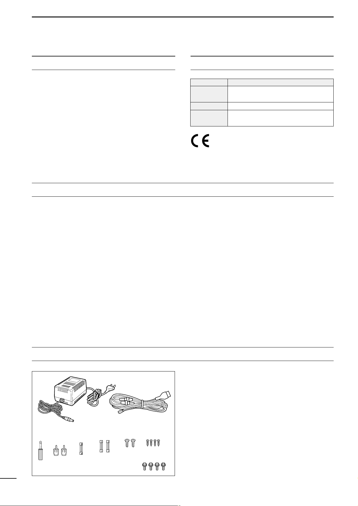
Accessories included with the IC-R8500:
Qty.
q AC adapter (AD-55A)* ……………………………………. 1
w DC power cable (OPC-023C) ………………………….. 1
e Mini plug (2-conductor, 3.5d)……………………………1
r Phono (RCA) plugs ……………………………………….. 2
t Fuse (FGMB 125 V 3 A; internal use) ……………….1
y Fuses (FGB 3 A; for DC cable) ……………………….. 2
u Screws (M4 × 12 for optional MB-23) ………………… 2
i Screws (C0 3 × 8 for optional MB-23 feet) ………….4
o Allen bolts (M5 × 8 for optional IC-MB12) ………….. 4
*Some versions are not supplied with an AC adapter.
WORD DEFINITION
RWARNING
Personal injury, fire hazard or electric
shock may occur.
CAUTION
Equipment damage may occur.
NOTE
If disregarded, inconvenience only. No risk
of personal injury, fire or electric shock.

TABLE OF CONTENTS
IMPORTANT ……………………………………………………. i
EXPLICIT DEFINITIONS …………………………………… i
PRECAUTIONS ……………………………………………….. i
UNPACKING ……………………………………………………. i
TABLE OF CONTENTS …………………………………….. ii
1 PANEL DESCRIPTION ………………………………. 1– 6
■ Front panel …………………………………………………………. 1
■ Rear panel …………………………………………………………. 5
■ Function display …………………………………………………..6
2 CONNECTIONS ………………………………………. 7– 10
■ Mounting installation ……………………………………………. 7
■ Required connections …………………………………………..8
■ Antenna connection ……………………………………………..9
■ Grounding ………………………………………………………….. 9
■ Tape recorder connections …………………………………. 10
■ Transceive function ……………………………………………. 10
■ Connecting to a PC …………………………………………… 10
■ Data demodulation terminal …………………………………10
3 FREQUENCY SETTING …………………………..11–12
■ Read me first …………………………………………………….. 11
■ Using the keypad ………………………………………………. 11
■ Using the main dial …………………………………………….12
■ Lock function …………………………………………………….. 12
4 RECEIVE FUNCTIONS ……………………………13–16
■ Initial settings ……………………………………………………. 13
■ Mode selection ………………………………………………….. 13
■ Squelch function ……………………………………………….. 14
■ Functions for FM ……………………………………………….. 14
■ Functions for SSB/CW ……………………………………….. 14
■ Data communications ………………………………………….16
5 MEMORY CHANNELS ……………………………. 17–22
■ General ……………………………………………………………. 17
■ Bank selection ………………………………………………….. 17
■ Channel selection ……………………………………………… 18
■ Programming ……………………………………………………. 19
■ Copy and paste (memory editing) ………………………… 19
■ Clearing …………………………………………………………… 19
■ Channel/bank names …………………………………………. 20
■ Assigning channels numbers ……………………………….21
6 SCANS …………………………………………………. 23– 28
■ Operation …………………………………………………………. 23
■ Mode select function ………………………………………….. 25
■ Specifying skip channel and frequency …………………25
■ Automatic bank limit/skip functions ………………………. 26
■ Voice scan control function …………………………………. 26
■ Programming scan edge frequencies …………………… 27
■ Scan speed/delay functions ………………………………… 27
7 SLEEP TIMER …………………………………………….. 29
8 SET MODE …………………………………………………. 30
■ General ……………………………………………………………. 30
■ Quick set mode items …………………………………………31
■ Initial set mode items …………………………………………. 31
9 CONNECTOR INFORMATION …………………. 33– 34
10 CONTROL COMMANDS ………………………. 35– 36
■ Command table ………………………………………………… 35
■ Data format ………………………………………………………. 35
11 MAINTENANCE …………………………………………. 37
■ Disassembly …………………………………………………….. 37
■ Fuse replacement ………………………………………………37
■ Level adjustments ……………………………………………… 37
■ Memory backup ………………………………………………… 37
■ CPU resetting …………………………………………………… 37
■ Cleaning …………………………………………………………… 37
12 OPTIONAL INSTALLATIONS ………………… 38– 39
■ UT-102
VOICE SYNTHESIZER UNIT
………………………….. 38
■ FL-52A
CW NARROW FILTER
…………………………………. 38
■ CR-293
HIGH STABILITY CRYSTAL UNIT
……………………. 39
13 TROUBLESHOOTING …………………………… 40–41
14 SPECIFICATIONS ……………………………………… 42
15 OPTIONS ………………………………………………….. 43
16 DOC ………………………………………………………….44
ii
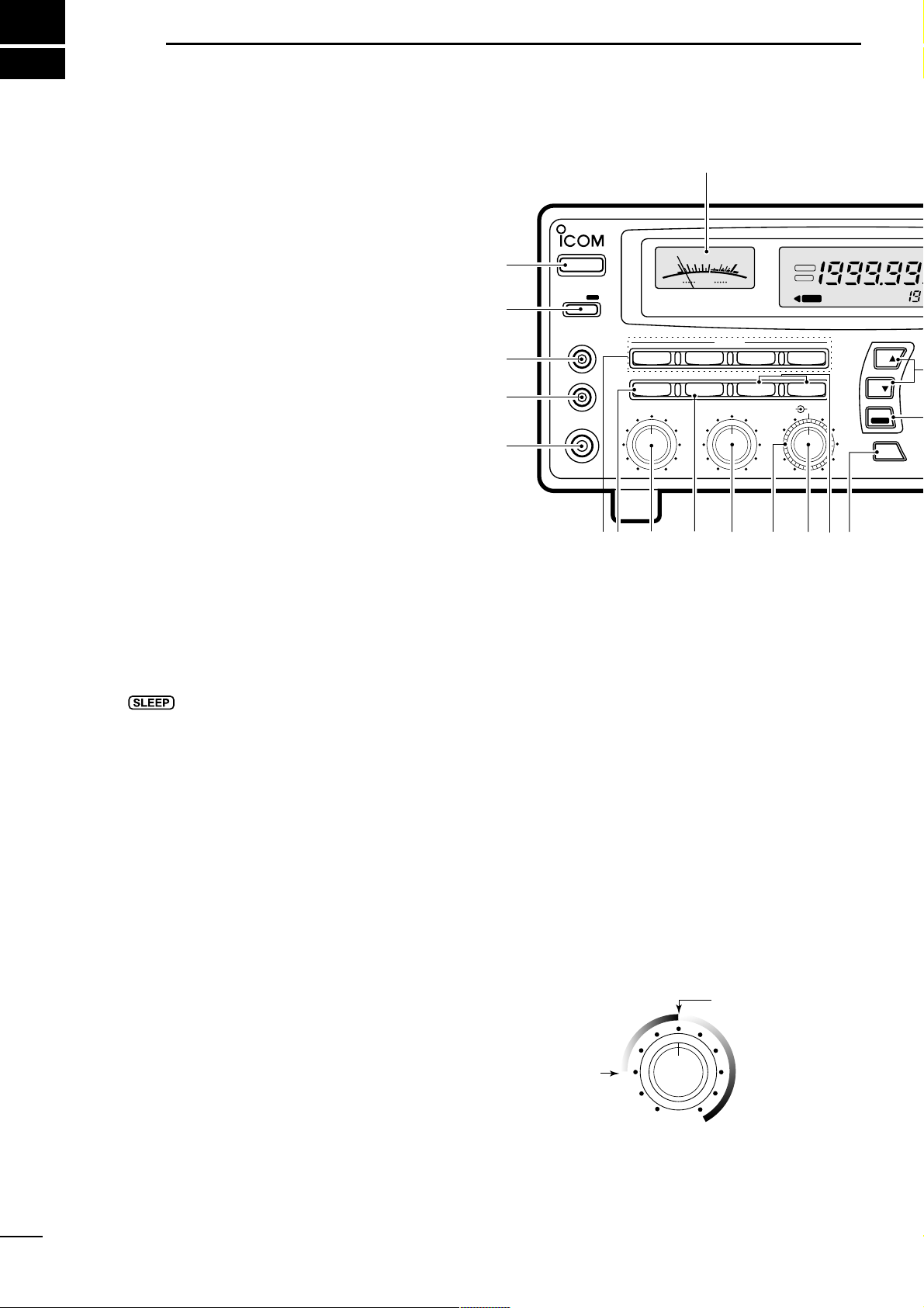
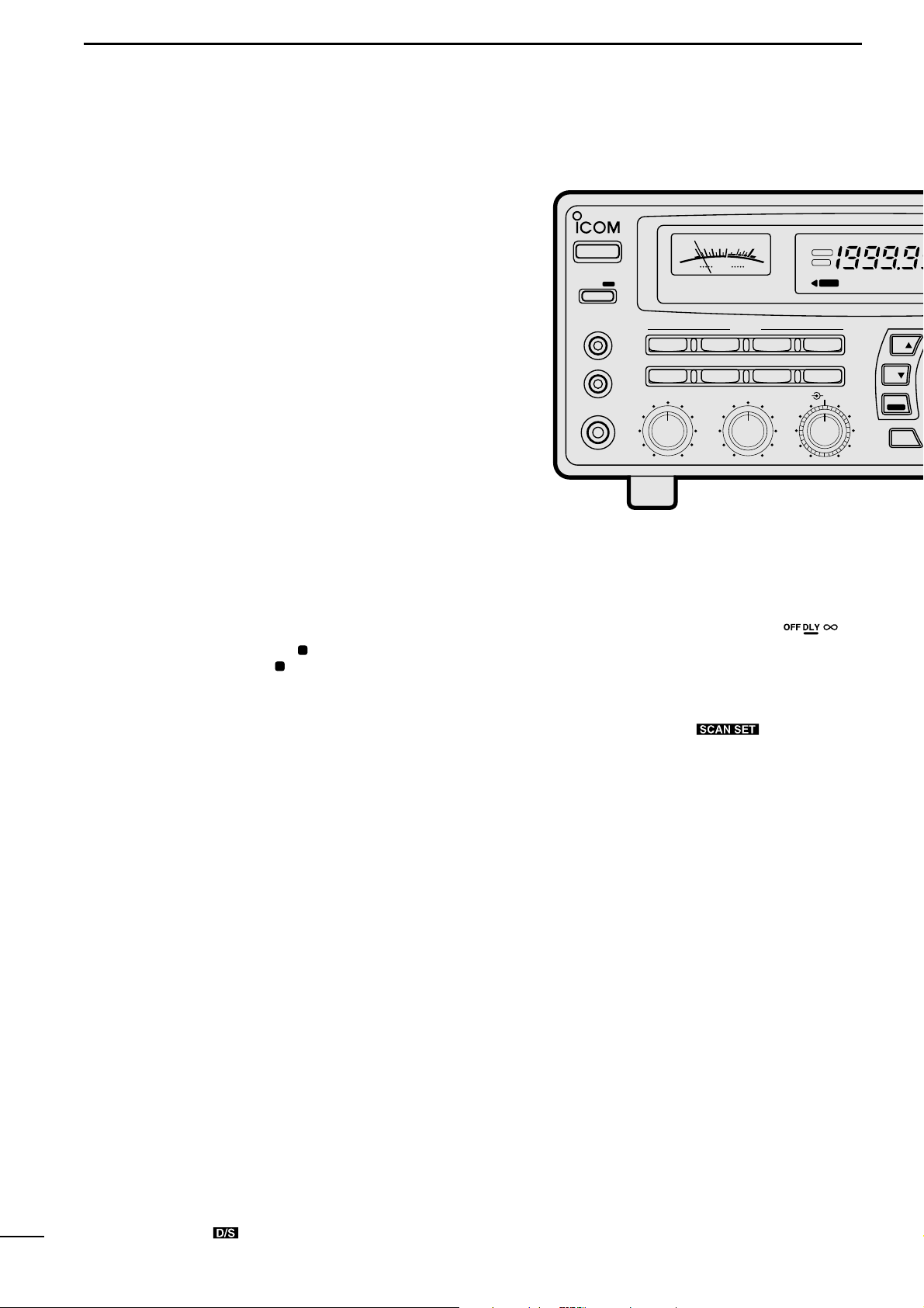
q POWER SWITCH [POWER]
Turns power ON and OFF.
w SLEEP/SET SWITCH [SLEEP/SET]
➥ Push momentarily to set the sleep timer (p. 29).
• Selectable times are 30, 60, 90, 120 min. or OFF.
•“ ” appears in the function display when the
sleep timer is set.
➥ Push for 1 sec. to enter quick set mode (p. 30).
• Use the [M-CH] selector and main dial to select items
and contents, respectively.
e
RECORDER REMOTE JACK [REC REMOTE] (p. 10)
Controls the running of a tape recorder for recording. Connects to the REMOTE jack on a tape
recorder.
r RECORDER JACK [REC OUT] (p. 10)
Outputs an audio signal. Connect to the AUX or
LINE IN jack on a tape recorder.
t HEADPHONE JACK [PHONES]
Accepts headphones with 4–16 Ω impedance.
• When headphones are connected, no receive audio comes
from the speaker.
• Stereo headphones can be connected, however, output
is monaural.
y MODE SWITCHES [WFM]/[FM]/[AM]/[SSB/CW]
(p. 13)
➥ Push to select an operating mode.
• The following keys toggle between several modes:
[FM] …………….. FM, FM narrow
[AM] ……………..AM, AM narrow, AM wide
[SSB/CW] …….. USB, LSB, CW, optional CW narrow
➥ When SSB/CW mode is selected, push [SSB/CW]
for 1 sec. to adjust the BFO frequency. (p. 15).
u NOISE BLANKER/AFC SWITCH [NB]/[AFC]
Activates the noise blanker function or automatic frequency control function.
• The noise blanker is used for removing pulse-type noise
when SSB, CW or AM mode is selected (p. 15).
• The automatic frequency control tunes the displayed frequency automatically when an off-center frequency is received. It activates when FM or WFM is selected (p. 14).
i AUDIO FREQUENCY GAIN CONTROL
[AF GAIN] (p. 13)
Rotate clockwise to increase the audio output; rotate
counterclockwise to decrease the audio output.
o AUTOMATIC GAIN CONTROL [AGC] (p. 15)
Toggles the time constant of the AGC circuit between “slow” and “fast.”
• When “fast” is selected, “AGC-F” appears.
• Cannot be used in FM or WFM modes.
!0 SQUELCH CONTROL [SQUELCH] (p. 14)
Varies the squelch threshold level (to mute noise
when receiving no signal).
!1 IF SHIFT CONTROL [IF SHIFT] (p. 14)
Shifts the center frequency of the receiver’s IF passband to reject interfering signals.
• Cannot be used in FM, WFM and AM modes.
1
1
PANEL DESCRIPTION
MODE
WFM
NB/AFC AGC 10dB 20dB
FM AM
APF
TS
TS
SPCH
SSB/CW
AF GAIN SQUELCH
PHONES
REC OUT
SLEEP/
REC
REMOTE
IF SHIFTAPF
SET
LOCK
COMMUNICATION RECEIVER
iC- r8500
POWER
SIGNAL
S
13579
+
20dB+60dB
@0
q
w
e
r
t
yio!0 !1 !2 !3 !4u
FM
RECV
BANK
10-ATT-20
APF-NAGC-FAFCNB
SLEEP
LOCK
ICOM
S-meter squelch
threshold
Noise squelch
threshold (not
available in SSB,
CW, WFM and
AM narrow modes)
• Signals below the
S-meter level
are muted.
2
1
PANEL DESCRIPTION
!2 AUDIO PEAK FILTER CONTROL [APF] (p. 15)
Adjusts the audio peak filter setting to pick up a desired audio frequency. Only valid when the [APF]
switch is ON.
• Clockwise rotation adjusts the filter setting higher; counterclockwise rotation adjusts the filter setting lower.
!3
ATTENUATOR SWITCHES [10dB]/[20dB]
Push to activate one of the attenuators.
➧ Push [10dB] to activate the 10 dB attenuator.
➧ Push [20dB] to activate the 20 dB attenuator.
➧ Push [10dB] +[20dB] to activate the 30 dB attenuator.
• 10 dB and 30 dB attenuator cannot be used below 500 kHz.
!4 AUDIO PEAK FILTER SWITCH [APF] (p. 15)
➥ Push momentarily to toggle the audio peak filter
circuit ON and OFF.
• Use the [APF] control to adjust the center of the audio
peak passband.
➥ When the audio peak filter circuit is ON, push for
1 sec. to toggle the filter setting between normal
and narrow.
•‘Narrow’ is available for SSB, CW and AM only.
!5
SPEECH/LOCK SWITCH [SPCH/LOCK]
➥ Push momentarily to activate the voice synthesiz-
er function and have the displayed frequency
announced.
• An optional UT-102
SPEECH SYNTHESIZER UNIT
is nec-
essary to activate the voice synthesizer function (p.38).
• Automatic announcement at signal detection during
scan is available. Refer to the “REC SPCH” item on
p. 31 for details.
➥
Push for 1 sec. to activate the lock function (p. 12).
• Push for 1 sec. again to cancel the lock function.
• The lock function action can be selected in set mode
to cover the main dial only, or to cover both the main
dial and front panel switches.
!6
TUNING STEP SWITCHES [TS▲]/[TS▼] (p. 12)
Select the tuning step for the main dial. Push [TS▲]
to select a larger tuning step; push [TS▼] to select
a smaller tuning step.
• 10 Hz, 50 Hz, 100 Hz, 1 kHz, 2.5 kHz, 5 kHz, 9 kHz, 10
kHz, 12.5 kHz, 20 kHz, 25 kHz, 100 kHz and 1 MHz are
selectable.
• Programmable tuning steps can be set between 0.5 and
199.5 kHz.
➠ To set programmable tuning steps, enter the desired
steps via the keypad, then push [TSY]or [TSZ].
!7
MAIN DIAL
Changes the operating frequency, set mode contents,
etc.
!8 BRAKE ADJUSTMENT SCREW
Adjusts the main dial tension.
!9 FUNCTION DISPLAY (p. 6)
Shows the selected frequency, mode, memory
name, etc.
@0 S-METER
➥ Shows the strength of the received signal.
➥ Shows the squelch threshold level when the
[SQUELCH] is rotated past the center position.
MEMO
SEL SKIP VSC
DLY
SCAN/
NAME
SCAN SET
PROG AUTO PRIO
M-SET BANK
M-CL MW
DELAY/SPEEDM-CH
D/S
1 QZ
GHI
PRS TUV WXY
ENT
BANK
BANK
JKL MNO
ABC DEF
.
;
,
4
78
0CE
ENT
M-CH
.
9
56
23
!9
!5
!6
!8
!7
SEL-CH SKIP-CH
OFF
kHz
DLY
M
Center frequency
is shifted up.
Center frequency
is shifted down.
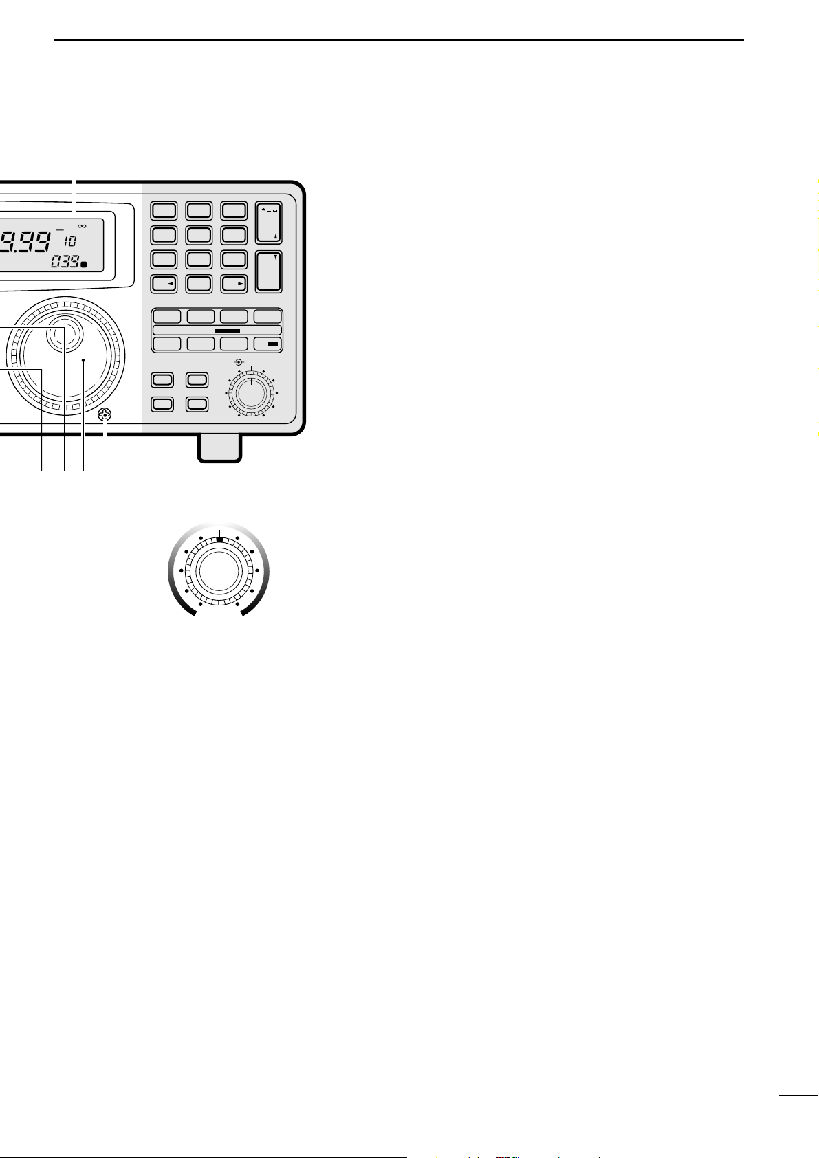
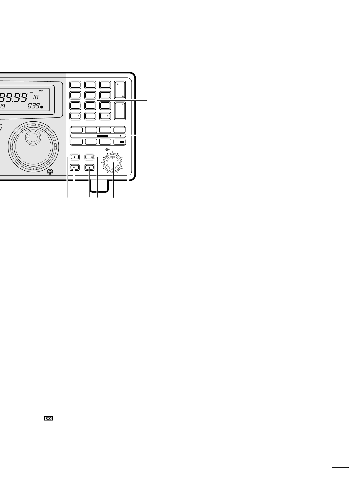
@1 MEMORY SET SWITCH [M-SET] (p. 19)
Used to ‘copy and paste’ the displayed frequency
into another memory channel.
• The first push is used to copy ( appears), and the sec-
ond push is used to paste ( disappears).
• Frequency, mode, tuning step, memory name, etc. can
be programmed into a temporary memory.
@2
MEMORY CLEAR SWITCH [M-CL] (p. 19)
Push and hold to clear the contents of the displayed
memory.
• Bank names cannot be cleared.
@3
MEMORY WRITE SWITCH [MW] (p. 19)
Push and hold to store the displayed frequency,
mode, tuning step, etc. into the selected memory
channel.
@4 BANK SWITCH [BANK] (p. 17)
➥ Push momentarily to toggle the bank limit func-
tion ON and OFF (p. 18).
• While “BANK” appears, only memory channels within
the selected bank can be selected via the [M-CH] selector.
➥ Push for 1 sec. to increase/decrease the number of
memory channels in the selected bank (p. 21).
@5 MEMORY CHANNEL SELECTOR [M-CH] (p. 18)
➥ Selects a memory channel in normal use.
• Clockwise rotation selects higher memory channel
numbers; counterclockwise rotation selects lower
memory channel numbers.
➥ Selects a set mode item when quick set mode or
initial set mode is selected (p. 30).
@6 DELAY/SPEED CONTROL [DELAY/SPEED] (p. 28)
Adjusts the scan delay time or scan speed depending on the [DLY ] switch setting.
• When scan delay time is assigned, this control adjusts
the scan delay time (scan pausing interval) during signal
reception. This setting is effective when “” is
selected for the scan resume condition.
• When scan speed is assigned, this control adjusts the
scan speed. In this case, scan delay time is determined
while setting.
@7
SCAN SWITCHES [SCAN ]
All of these switches are related to the scan function
in some way as follows:
[MEMO] (p. 23)
➥ Push momentarily to start/stop memory scan.
➥ Push numeral keys, then this key to start memo-
ry scan in the specified bank.
➥ Push this key, then a mode switch to activate
mode select scan function.
➥ Push for 1 sec. to set automatic bank and skip
functions.
• The bank limit function and/or memory skip functions
are activated automatically when “AUTO” is selected
and scan is started.
[SEL] (p. 23)
➥ Push momentarily to start/stop memory select
scan.
➥ Push for 1 sec. to set the memory channel as a
select channel.
[PROG] (p. 24)
➥
Push momentarily to start/stop programmed scan.
➥ Push numeral keys, before or after pushing this
key to start programmed scan using the specified
scan edge group.
• 10 scan edge groups are available.
➥ Push for 1 sec. to program scan edges for pro-
grammed scan.
MODE
WFM
NB/AFC AGC 10dB 20dB
FM AM
APF
TS
TS
SPCH
SSB/CW
AF GAIN SQUELCH
PHONES
REC OUT
SLEEP/
REC
REMOTE
IF SHIFTAPC
SET
LOCK
COMMUNICATION RECEIVER
iC- r8500
POWER
SIGNAL
S
13579
+
20dB+60dB
FM
RECV
BANK
10-ATT-20
APF-NAGC-FAFCNB
SLEEP
LOCK
ICOM
4
1
PANEL DESCRIPTION
[SKIP] (p. 25)
➥ Push momentarily to toggle the skip function ON
and OFF for any scan.
• Automatic skip activation is available with the [MEMO]
switch.
➥ Push for 1 sec. to set the memory channel as a skip
channel.
[AUTO] (p. 24)
➥ Push momentarily to start/stop auto write scan.
➥ Push for 1 sec. to select the written memories
condition for the auto write scan.
• Two conditions are available, clear auto-written memories before scan starts; and, keep auto written memories before scan start.
[VSC] (p. 26)
Push to toggle the voice scan control function ON
and OFF.
• The VSC function resumes the scan when a detected signal does not contain voice components.
•“VSC” appears while the voice scan control function is
activated.
[PRIO] (p. 25)
➥ Push momentarily to start/stop priority scan.
• Priority scan can be used in combination with other
scans.
➥ Push for 1 sec. to enter the priority channel pro-
gramming condition.
[DLY ] (p. 27)
➥ Push momentarily to select a scan resume condi-
tion.
➧ “OFF” is underscored: scan pauses on a signal until it
disappears, then resumes 3 sec. after that.
➧ “DLY” is underscored: scan resumes according to the
[DELAY/SPEED] control setting. When a signal disappears, scan resumes 3 sec. later.
➧ “
∞
” is underscored: scan is cancelled when receiving
a signal.
➥ Push for 1 sec. to enter the delay time/scan speed
setting condition.
• The function of the [DELAY/SPEED] control can be selected.
@8
KEYPAD
The keypad can be used for several functions as below:
• Keypad then [ENT] (then [MW])
— Direct frequency input.
• Keypad then [M-CH]
— Memory channel selection.
• [CE•
NAME] then keypad
— Alphanumeric input for memory, bank names, etc.
• Keypad then [TSY] or [TSZ]
— Arbitrary tuning step setting.
• Keypad then [MEMO] or [SEL]
— Specify memory bank then start memory scan or se-
lect memory scan.
• Keypad then [PROG] or [AUTO]
— Specify scan edge group, then start programmed
scan or auto write scan.
MEMO
SEL SKIP VSC
DLY
SCAN/
NAME
SCAN SET
PROG AUTO PRIO
M-SET BANK
M-CL MW
DELAY/SPEEDM-CH
D/S
1 QZ
GHI
PRS TUV WXY
ENT
BANK
BANK
JKL MNO
ABC DEF
.
;
,
4
78
0CE
ENT
M-CH
.
9
56
23
@2 @3@1 @4 @5 @6
@7
@8
SEL-CH SKIP-CH
OFF
kHz
DLY
M
IC-R8500
5
1
PANEL DESCRIPTION
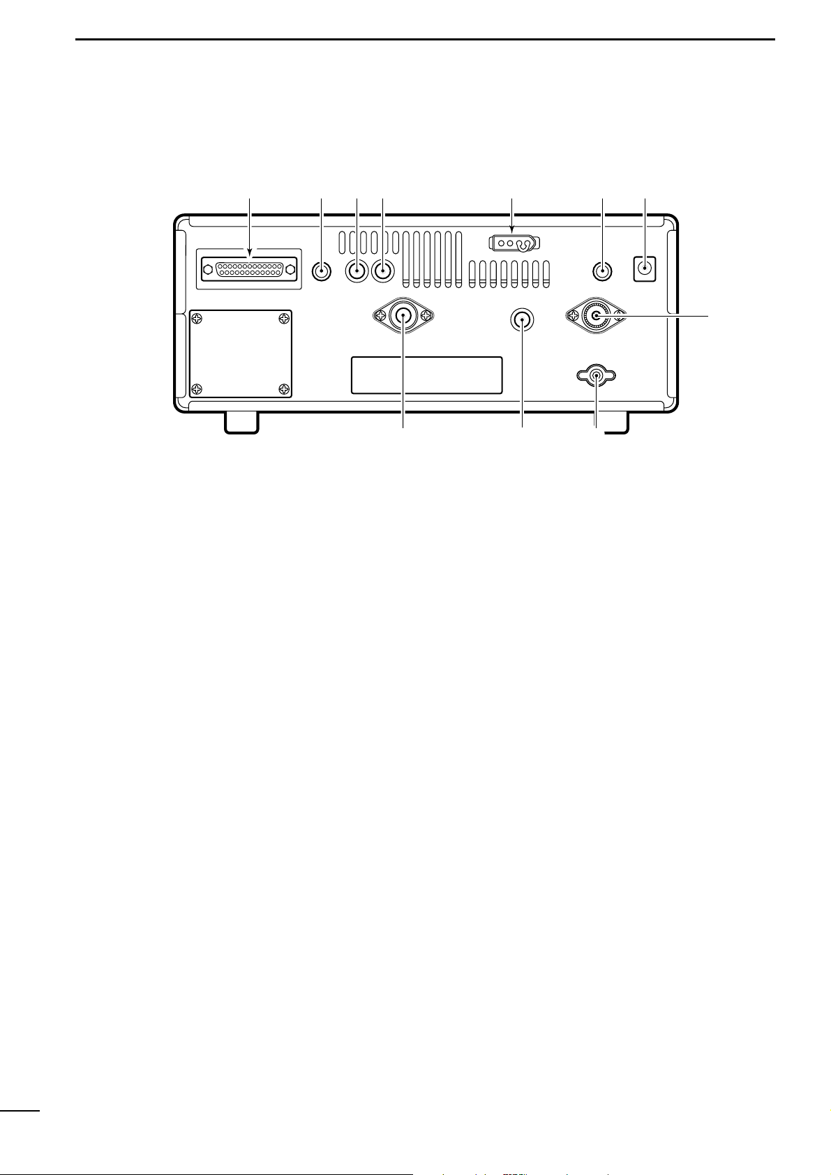
■ Rear panel
q
RS-232C CONNECTOR (p. 10)
Connects an RS-232C cable. An RS-232C cable
can be used to connect the IC-R8500 to a PC. In this
way commands can be sent to the receiver via the
PC.
w CI-V REMOTE CONTROL JACK (p. 10)
Allows connection to an Icom CI-V system transceiver or another receiver for the transceive function.
Also connects to a PC with several receivers for
command control via an optional CT-17 CI-
V LEVEL
CONVERTER
.
e IF OUT JACK
Outputs a 10.7 MHz IF signal with 9 V DC for an external equipment.
r AGC JACK (p. 16)
This jack has functions which are selectable through
internal receiver settings.
• Outputs an AGC signal for an external equipment (de-
fault).
• Outputs audio detected signal without de-emphasis for
9600 bps data detection (FM mode only).
t DC 13.8 V JACK (p. 
➥ Plug in the jumper connector here when using the
supplied* AC adapter.
➥ Connects to a 13.8 V DC power source using the
supplied DC cable when the AC adapter is not
connected.
*Not supplied with some versions.
y EXTERNAL SPEAKER JACK
Connects an 8 Ω external speaker.
• When an external speaker is connected, the internal
speaker does not function.
u DC IN JACK (p.
Connects the supplied* AC adapter.
• A regulator circuit has been designed between this connector and the DC 13.8 V jack.
• Be sure the jumper connector is connected to the DC
13.8 V jack.
*Not supplied with some versions.
i HF 50 Ω ANTENNA CONNECTOR (p.
Connects an antenna to cover the frequency range
below 30 MHz.
• Use a coaxial cable and a PL-259 connector.
• Be sure this connector is selected in quick set mode
(p. 31).
o GROUND TERMINAL (p. 9)
Connect this terminal to a ground.
!0 HF 500 Ω ANTENNA CONNECTOR (p.
When a 500 Ω long wire antenna is used for HF band
receiving, this connector is used instead of the 50 Ω
antenna connector.
• Set the “HF ANT” item to 500 to use this connector
(p. 31).
!1 VHF/UHF ANTENNA CONNECTOR (p.
Connects an antenna to cover the frequency range
over 30 MHz.
• Use a coaxial cable and type-N connector.

6
1
PANEL DESCRIPTION
■ Function display
q
REMOTE INDICATOR (p. 35)
Appears when a level control command is received from a
PC via CI-V data.
• When this indicator appears, the control knob’s setting is
ignored.
• This indicator will disappear when the control knob is rotated.
w MODE INDICATORS (p. 13)
Show the operating mode.
e FREQUENCY READOUT
Shows the operating frequency.
r SKIP INDICATOR (p. 25)
➥ Appears when the skip function is activated.
➥ Flashes during scan when the skip function is ac-
tivated by the auto skip function.
t VSC INDICATOR (p. 26)
Appears when the voice scan control function is
activated.
y
SCAN RESUME CONDITION INDICATORS (p. 27)
Show the selected scan resume condition.
u TUNING STEP INDICATORS (p. 12)
Show the selected tuning step.
•
“” appears when a programmable tuning step is selected.
i TEMPORARY MEMORY INDICATOR (p. 19)
➥ Appears when [M-SET] is pushed to indicate that
a frequency is being temporarily saved.
➥ Disappears when the temporary memory is past-
ed into another memory channel.
o MEMORY CHANNEL READOUT (p. 17)
Shows the selected memory channel number.
!0 SKIP CHANNEL INDICATOR (p. 25)
Appears when the selected memory channel is set
as a skip channel.
!1 MEMORY NAME INDICATORS (p. 20)
Display names programmed into a memory, or scan
group.
!2 SELECT CHANNEL INDICATOR (p. 23)
Appears when the selected memory channel is set
as a select channel.
!3 BANK NUMBER INDICATOR (p. 17)
Shows the selected memory bank number.
!4 BANK INDICATOR (p. 18)
➥ Appears when the bank limit function is activated.
➥ Flashes during scan when the bank limit function
is activated by the auto bank function.
!5 BANK NAME INDICATOR (p. 20)
Displays names programmed into a bank.
!6 AUDIO PEAK FILTER INDICATOR (p. 15)
“APF” or “APF-N” appears when the audio peak filter function is activated.
!7 ATTENUATOR INDICATORS
Appear when the RF attenuator is activated.
!8 AUTOMATIC GAIN CONTROL INDICATOR (p. 15)
AGC-F appears when AGC fast is selected; no indication appears when AGC slow is selected.
!9 RECEIVE INDICATOR
Appears while receiving.
@0 FM CENTER INDICATORS (p. 14)
Appear when the received signal is not tuned to its
center frequency.
@1 NOISE BLANKER INDICATOR (p. 15)
Appears when the noise blanker circuit is activated.
@2 AFC INDICATOR (p. 14)
Appears when the automatic frequency control
function is activated in either FM or WFM modes.
@3 LOCK INDICATOR (p. 12)
Appears when the main dial or front panel switches
are locked.
@4 SLEEP INDICATOR (p. 29)
Appears when the sleep timer is set.
REMOTE
WFM
RECV
AMUSBLSBCW
BANK
10-ATT-20
APF-NAGC-FAFCNB
SEL-CH SKIP-CH
WIDE NAR
SKIP VSC
OFF
MHz kHz
DLY
SLEEP
LOCK
M
P
qwerty
u
io!0!1!2!3!4!5!6!7!8!9@0 @0
@1
@2
@3
@4
7
2
CONNECTIONS
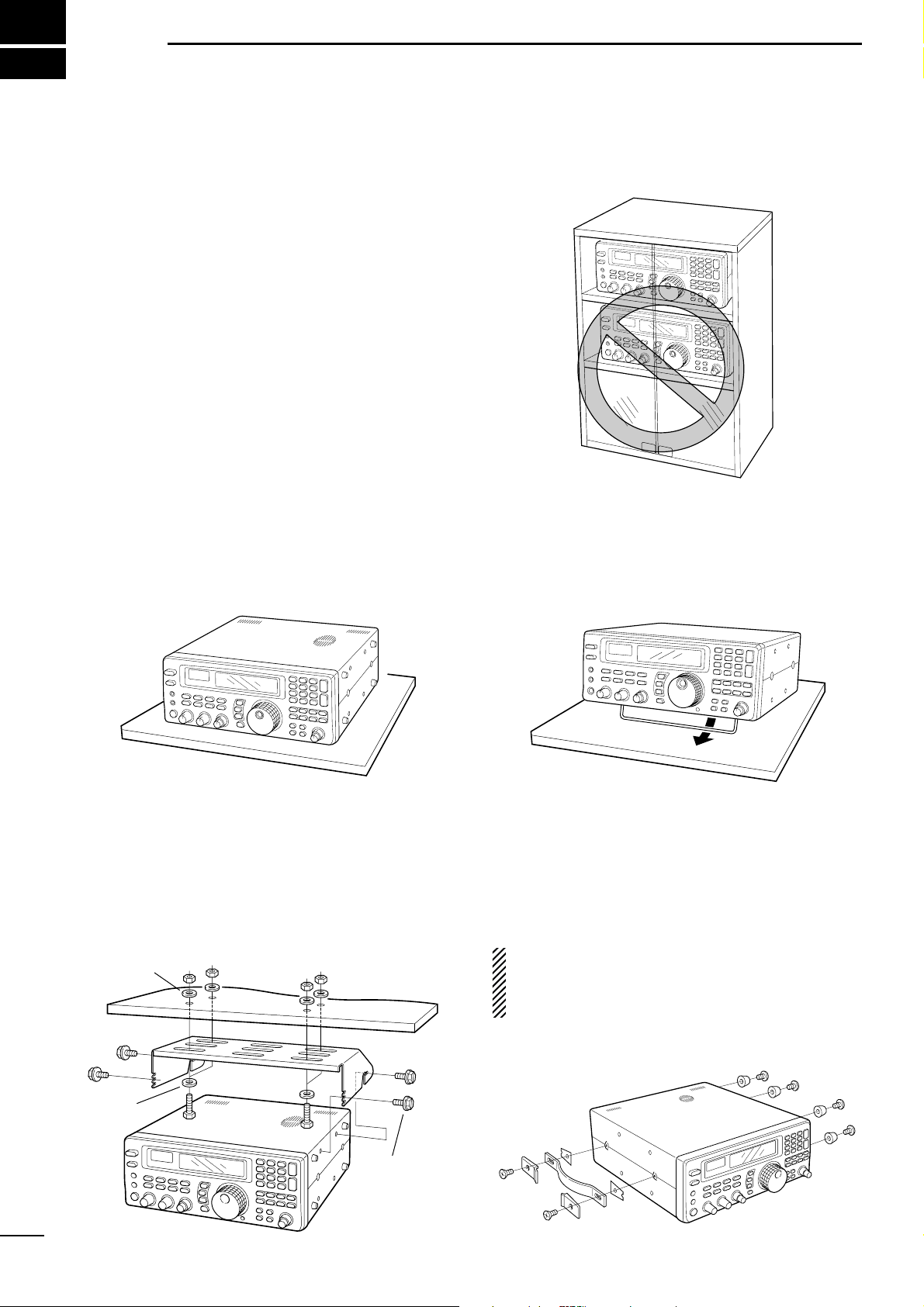
■ Mounting installation
D Location
Select a location for the receiver that allows adequate
air circulation and access to the front and rear panels.
Do not place in areas subject to extreme heat, cold, or
vibrations, or near TV sets, radios and electromagnetic
sources.
Be careful of the internal temperature of the receiver.
Installation into a rack or other enclosed area may increase the internal temperature over the useable temperature range. Specifications are not guaranteed
under such conditions.
D Receiver stand
The base of the IC-R8500 has an adjustable stand for
desktop use. Set the stand to one of two angles depending on your operating conditions.
D Optional bracket and carrying handle
• Mounting bracket
An optional mounting bracket is available to install the
radio under a table, on a wall, in a vehicle, etc.
Select an area to mount the receiver keeping in mind
that the weight of the IC-R8500 is approx. 7 kg.
• Carrying handle
An optional handle allows you to easily carry and
transport the receiver.
Attach the MB-23
CARRYING HANDLE
with the supplied
rubber feet as shown.
CAUTION: The screws supplied with the MB-23
cannot be used with the IC-R8500. Use the screws
supplied with the IC-R8500 when attaching the
MB-23.
Flat washer
Spring
washer
Allen bolt
supplied with
the IC-R8500.
8
2
CONNECTIONS
■ Required connections
IC-R8500
Supplied DC power cable
Unplug the jumper plug
from the [DC13.8V] jack.
AC adapter AD-55/A/V
Connect
either power
source
The jumper plug must be
connected to the [DC 13.8V]
jack.
Ground connection (p. 9)
HF antennaLong wire antennaVHF/UHF wide band
antenna
Computer control
(p. 10)
External speaker
(p. 43)
High speed data
connection (p. 16)
0.1–30 MHz coverage0.1–30 MHz coverage30 MHz –2 GHz coverage
The optional AH-7000 is
available for 25 MHz to 1.3
GHz coverage.
Select the active antenna connector in quick set mode (p. 31)
9
2
CONNECTIONS
■ Antenna connection
Antennas play a very important role in receiver operation. Connecting a poor quality antenna to the
IC-R8500 will result in less than optimum performance.
The IC-R8500 requires at least 2 antennas for full frequency coverage: one for 0.1 to 30 MHz and one for
30 to 2000 MHz.
D Using a long wire antenna for HF bands
The IC-R8500 has a 500 Ω phono (RCA) antenna
connector for the HF bands. When using a long wire
antenna, instead of a 50 Ω matched antenna, use one
as long as possible (at least 10 m, 33 ft) and select the
active connector as follows:
q Push [SLEEP/ ] for 1 sec. to enter quick set
mode.
w Rotate the [M-CH] selector to select the “HF ANT”
item.
e
Rotate the main dial to select the antenna connector.
r Push [SLEEP/ ] momentarily to exit quick set
mode.
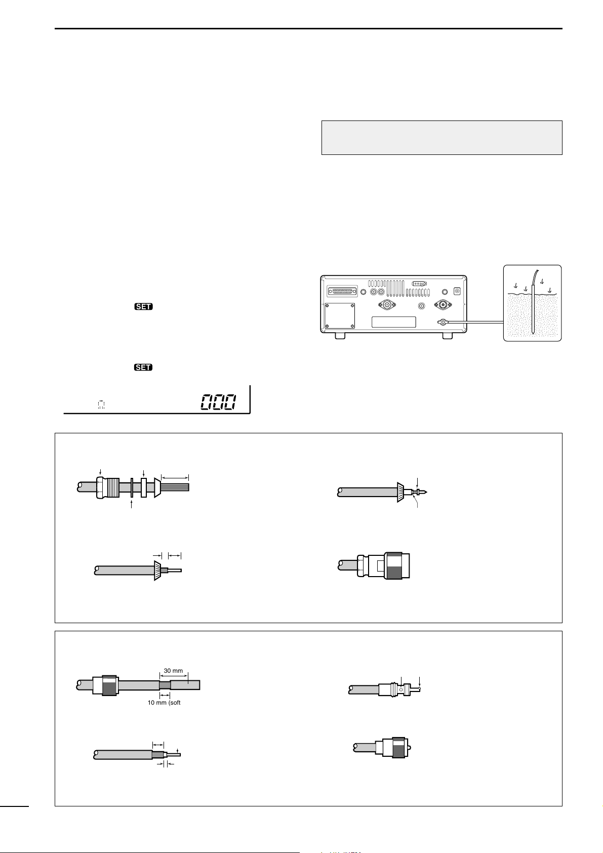
■ Grounding
To prevent accidents involving electricity and interference from transceivers, ground the receiver through
the [GND] terminal on the rear panel.
For best results, connect a heavy gauge cable to a
water pipe or long, earth-sunk copper rod. Make the
distance between the [GND] terminal and ground as
short as possible.
RWARNING: NEVER use a gas pipe or electri-
cal conduit pipe for grounding.
;;
;;
500 HF ANT
TYPE-N CONNECTOR INSTALLATION EXAMPLE
Nut Rubber gasket
qe
Washer
Clamp
15 mm
Slide the nut, washer,
rubber gasket and
clamp over the
coaxial cable, then
Solder hole
No space
Soft solder the center
conductor. Install the
center conductor pin and
solder it.
cut the end of the
w
(10 mm ≈
3
⁄8 in)
3 mm 6 mm
Center conductor
cable evenly.
Strip the cable and
fold the braid back
over the clamp.
r
Plug body
Carefully slide the plug
body into place aligning
the center conductor pin
on the cable. Tighten the
nut onto the plug body.
• Be sure the center
conductor is the same
height as the plug body.
PL-259 CONNECTOR INSTALLATION EXAMPLE
qe
Coupling ring
30 mm
10 mm (soft solder)
Slide the coupling ring
down. Strip the cable
jacket and soft solder.
solder solder
Slide the connector
body on and solder it.
w
(10 mm ≈
3
⁄8 in)
10 mm
1–2 mm
Soft
solder
Strip the cable as
shown at left. Soft
solder the center conductor.
r
Screw the coupling ring
onto the connector
body.
10
2
CONNECTIONS
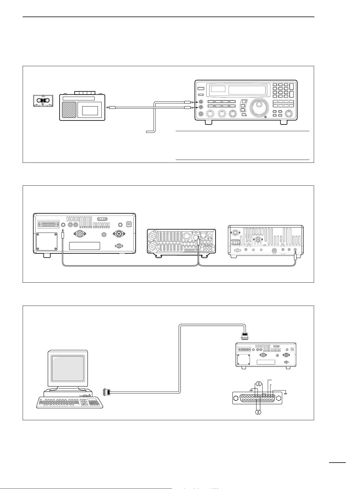
■ Tape recorder connections
The [REC OUT] jack has 350 mV rms/4.7 kΩ output
for connection to other audio equipment.
■ Transceive function
Icom CI-V transceivers or receivers can be connected via the [REMOTE] jack. The frequency and mode
become the same* when either radio is changed.
* When a set frequency is out-of-range for one of the con-
nected transceivers or receivers, the connected radio’s
frequency/mode does not change.
■ Connecting to a PC
■ Data demodulation terminal
See p. 16 for details regarding connection and operation.
The IC-R8500 can connect directly to a personal
computer providing control of multiple functions such
as instant frequency/name programming using
appropriate software. See pgs. 35, 36 for the control
command table.
✔ Convenient:
When an optional UT-102
VOICE SYNTHESIZER UNIT
is
installed, detected frequencies during scanning can
be recorded. See pgs. 31, 32 for settings.
[REC REMOTE] jack: Grounds when a signal is
received and squelch opens. If a tape recorder has
a control terminal, this jack can be used for recording control. (2 A/DC max.)
• Be sure the “CIV TRAN” item is turned ON in initial set mode (p. 32).
A DB9/DB25 adapter may be
required depending on the PC’s
connector.
[AUX IN] or
[LIVE IN] jack
IC-R8500
[REC
REMOTE]
SCAN SET
[REC OUT]
350 mVrms
4.7 kΩ
Personal computer
RS-232C
cable
8
13
25 14
20 6
IC-R8500
3.TXD (data output)
2.RXD (data input)
1
11
3
FREQUENCY SETTING
■ Read me first
The IC-R8500 uses memory channels for storage of
frequencies (as well as mode, tuning steps, etc.).
When turning power OFF or changing memory channels, the previously displayed frequency cannot be
recalled unless it has been stored into a memory
channel. Therefore, when you want to keep a displayed frequency for later recall, you must program it
into a memory channel by pushing [MW] for 1 sec.
✔ Convenient:
Use [M-SET] to program a displayed frequency (and
its mode, etc.) without overwriting the currently selected memory. See p. 19.
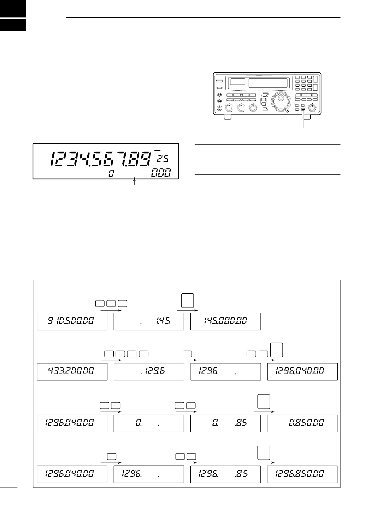
■ Using the keypad
q Push the numeral keys on the keypad to enter the
MHz digits for the desired frequency.
• If a key is mistakenly pushed, push [CE≈] and start
again from the beginning.
• When entering the same MHz digits as the displayed
frequency, this step can be skipped.
w Push [
•
Ω
].
e Push the numeral keys to enter the frequency digits
below 1 MHz.
• If a key is mistakenly pushed, push [CE≈] and start
again from the beginning.
r Push [ENT] to set the input frequency.
• When pushing [ENT] after entering the MHz digits, zeros
are automatically entered for the kHz digits.
[EXAMPLE]: SETTING THE FREQUENCY USING THE KEYPAD
• To set to 145.00 MHz
1
45
ENT
• To set to 1296.040 MHz
1
29 6
•
04
ENT
• To set to 850 kHz
(0.85 MHz)
08
5
•
ENT
• To change from 1296.040
to 1296.850 MHz
8
5
•
ENT
Push [MW] for 1 sec. after tuning.
FM
OFF
kHz
DLY
∞
USR-A BLANK
“BLANK” appears in the memory name area until
[MW] is pushed for 1 sec.
12
3
FREQUENCY SETTING
■ Using the main dial
Rotate the main dial to change the frequency.
• The frequency changes in increments determined by the
selected tuning step (see below).
• When the lock function is activated (“LOCK” appears) the
frequency cannot be changed.
D Selecting a tuning step
13 preset tuning steps are available plus 1 programmable tuning step (see below). The preset tuning steps are:
10 50 100 Hz
1 2.5 5 9 10 12.5 20 25 100 kHz
1 MHz
Push [TSY] or [TSZ] to change the selected tuning
step.
D Setting the programmable tuning step
The programmable tuning step can be set between the
range of 0.5–199.5 kHz (in 0.5 kHz steps) for each
memory independently.
q Push the numeral keys on the keypad that corre-
spond to the tuning step you wish to program.
w Push [TSY] or [TSZ] to set the programmable tun-
ing step to the selected value.
• The programmable tuning step is automatically selected
as the active tuning step.
■ Lock function
The lock function electronically locks the indicated frequency from accidentally being changed.
Push [
SPCH ] for 1 sec. to toggle the lock func-
tion ON and OFF.
•“LOCK” appears in the function display while the lock
function is activated.
D Setting the lock function coverage
The lock function can be set to lock the main dial only
or, the main dial and most of the front panel switches.
q Push [SLEEP ] for 1 sec. to enter quick set
mode.
w Rotate the [M-CH] selector to select the “LOCK”
indication.
e Rotate the main dial to set the lock function cover-
age to “DIAL” or “PANEL.”
r Push [SLEEP ] momentarily to exit quick set
mode.
SCAN SET
[TSY]
[TSZ]
MHz kHz
P
Tuning step
indicators
MHz kHz
P
appears when the programmable tuning step
is selected.
or appears to indicate the units of
the selected tuning step.
[EXAMPLE]: Setting the programmable tuning step to 50 kHz.
0
5
FM
LOCK
*ICOM
IC-R8500
OFF DLY
∞
kHz
TS
kHzkHz
TS
(or )
FM
OFF DLY
P
kHz
∞
LOCK
DIAL
kHz
Loading…
- Широкий диапазон: 0.1-2000МГц с шагом 10Гц.
- Виды модуляции: SSB (USB,LSB), CW, AM, FM, WFM, включая специальные виды: узкая CW, широкая и узкая AM, узкая FM (для приема узкой CW требуется фильтр FL-52A).
- Сверхвысокая стабильность частоты. Высокостабильный кварц (TCXO) обеспечивает стабильность менее +/-100Гц (до 30 МГц) и менее 0.3 ppm (свыше 30 МГц), что повышает качество работы схем PLL и DDS.
-
Повышенное качество приема.
- Схемы сдвига промежуточной частоты (IF shift) и режекторный аудио фильтр (APF) впервые встроены в приемник такого класса. Сдвиг ПЧ позволяет разделить близкорасположенные сигналы. Режекторный фильтр используется для подавления интерференции от наложенных друг на друга сигналов, что особенно эффективно при работе с CW . Качество приема повышается также за счет применения шумоподавителя (NB), ВЧ-аттенюатора, переключаемой АРУ и цифровой АПЧ. Чувствительность приемника в диапазоне от 2 до 1300 МГц практически не зависит от частоты.
-
Расширенные функции использования памяти.
- В каждом канале запоминается частота, вид модуляции (включая ширину полосы), шаг настройки и т.д. Для повышения эффективности память разделена на 20 банков по 40 каналов и на области автоматической записи или пропуска по 100 каналов. Каналам и банкам памяти можно присвоить буквенные имена длиной 8 и 5 символов соответственно. Дополнительно в памяти выделено 20 каналов для границ сканирования и 4 приоритетных канала. Количество каналов в каждом банке может быть изменено. Функция редактирования памяти позволяет производить копирование и вставку содержимого каналов.
-
Компьютерный интерфейс.
- На задней панели приемника расположен не только разъем CI-V, но и последовательный порт для непосредственного подключения к компьютеру. Обмен осуществляется в разработанном фирмой ICOM формате CI-V и позволяет как считывать данные (частоты, уровень сигнала), так и управлять всеми функциями приемника. Приемник ICOM IC-R8500 поддерживается большинством управляющих программ (ARCON, FILIN и др.).
- 7 типов сканирования: программируемое, диапазонное, по каналам памяти, по видам сигнала, по группам каналов памяти, приоритетное, с автоматической записью частот. Скорость сканирования плавно регулируется до 40 каналов в секунду (как в режиме сканирования по каналам памяти, так и при программируемом сканировании). Время задержки также плавно регулируется. Интеллектуальная система .поиска голоса. VSC (Voice Scan Control) позволяет пропускать немодулированные и шумовые сигналы.
- Удобство настройки. Предусмотрено два метода ввода частоты: с клавиатуры или с помощью ручки настройки. Шаг настройки регулируется в пределах от 10Гц до 1МГц. Дополнительно существует режим программируемого шага, устанавливаемого для каждого канала в пределах от 0.5 до 100кГц с разрешением 0.5кГц.
-
Автоматическое выключение (Sleep timer)
- 3 антенных разъема — SO-239, RCA и N-type
- Стрелочный S-метр и индикатор центральной частоты
- Шумоподавитель с предустановкой порогового уровня сигнала
- Разъемы REC и REC-remote для записи сигналов и управления магнитофоном
- При установке платы синтезатора речи UT-102 возможна запись принимаемых частот (на английском языке)