
Инструкция по эксплуатации (мануал) на русском языке, для любительского КВ трансивера ICOM IC-718.
Инструкция выполнена профессиональным переводчиком — радиолюбителем, в оригинальном качестве.
Инструкция поставляется в виде книги — распечатана на листах формата А4 и сшита пружинным переплетом.
Инструкция содержит 65 страниц.
Внимание!!!
Приобретая в нашей компании любительский трансивер ICOM IC-718, вы получаете данную инструкцию бесплатно!!
Предупреждение!!!
Все права защищены! Все права на данный перевод инструкции по эксплуатации трансивера ICOM IC-718, являются собственностью компании «Радиоэксперт»! Ничто из нее, приобретенной или полученной бесплатно от компании «Радиоэксперт», не может быть перепечатано, заложено в компьютерную память или скопировано в любой форме — электронной, механической, фотокопии или какой-то другой — без письменного разрешения компании «Радиоэксперт». Распространение данной инструкции всей или любых ее частей, платное или бесплатное, в любой форме ЗАПРЕЩЕНО!!!
-
Page 1: Icom IC-718
INSTR UCTION MANU AL HF ALL BAND TRANSCEIVER i718[…]
-
Page 2: Icom IC-718
i IMPORTANT READ THIS INSTRUCTION MANUAL CAREFULLY before attempting to operate the transceiver. SAVE THIS INSTRUCTION MANUAL. Th is manual contains important safety and operating instructions for the IC-718. EXPLICIT DEFINITIONS PRECAUTIONS R WARNING HIGH VOLTAGE! NEVER attach an antenna or internal antenna connector during transmission. This may […]
-
Page 3: Icom IC-718
q w e r 1 1 T ABLE OF CONTENTS The transceiver comes wit h the following accessories. Qty. q DC power cable …………………………………………… 1 w Hand microphone (HM-36) …………………………… 1 e Fuse (FGB 20 A; for DC cable) ……………………… 1 r Fuse (FGB 4 A; internal use) ………………………… 1 […]
-
Page 4: Icom IC-718
n Front panel q POWER SWITCH [PWR] Push momentarily to turn power ON. • Turn the optional DC power supply ON in advance. Push for 1 sec. to turn power OFF. While pushing and holding [SET], push [PWR] to enter the initial set mode. (p. 41) w MICROPHONE CONNECTOR [MIC] Accepts supplied or optional microphone. • See p. 55 for appropria[…]
-
Page 5: Icom IC-718
3 2 P ANEL DESCRIPTION • Push several times (or push and hold) [ √ DN]/[UP ∫ ] until desired memory channel appears. • After pushing [F-INP/ENT], push desired memory channel number from the keypad, then push [FINP/ ENT] again to select the memory channel directory. • Push [CH] to exit the memory channel select function. !2 MEMORY CHANNEL […]
-
Page 6: Icom IC-718
4 2 P ANEL DESCRIPTION n Front panel (continued) @2 VFO/MEMORY SWITCH/1 [V/M•1] (pgs. 16, 35) T o g g l e s t h e o p e r a t i n g m o d e b e t w e e n V F O mode or memory mode when pushed. @3 MEMORY WRITE SWITCH/4 [MW•4] (p. 36) Stores the displayed frequency and operating mode into the selected memory channel when pushed for 1 sec.[…]
-
Page 7: Icom IC-718
n Function display q LOCK INDICATOR (p. 19) Appears when the dial lock function is in use. w RECEIVE INDICATOR Appears while receiving a signal or when the squelch is open. e TUNE INDICATOR Appears while the automatic tuning function is activated. r TRANSMIT INDICATOR Appears while transmitting. t FUNCTION INDICATORS “P.AMP” appears when an[…]
-
Page 8: Icom IC-718
6 2 P ANEL DESCRIPTION n Rear panel q ANTENNA TERMINAL [ANT] (p. 10) Connects a 50 Ω antenna with a PL-259 connector and a 50 Ω coaxial cable. w DC POWER SOCKET [DC 13.8V] (p. 12) Accepts 13.8V DC through the supplied DC power cable. e TUNER CONTROL SOCKET [TUNER] (p. 14) Accepts the control cable from an optional AH-4 AUTOMATIC ANTENNA TUNER .[…]
-
Page 9: Icom IC-718
7 2 P ANEL DESCRIPTION D ACC SOCKET INFORMATION • A CC soc ket • When connecting the A CC con version cable (OPC-599) A CC PIN # NAME DESCRIPTION SPECIFICA TIONS COLOR 1 8 V Regulated 8 V output. Output voltage : 8 V ±0.3 V Output current : Less than 10 mA brown 2 GND Connects to ground. red 3 SEND Input/output pin. Goes to ground when transmi[…]
-
Page 10: Icom IC-718
8 2 P ANEL DESCRIPTION n Microphone (HM-36) q UP/DOWN SWITCHES [UP]/[DN] Change the selected r eadout frequency or memory channel. • Continuous pushing changes the frequency or memory channel number continuously. • The [UP]/[DN] switch can simulate a key paddle. Preset in the CW PADDL in initial set mode. (p. 31) w PTT SWITCH Push and hold to t[…]
-
Page 11: Icom IC-718
3 9 INST ALLA TION AND CONNECTIONS n Unpacking After unpacking, immediately report any damage to the delivering carrier or dealer. Keep the shipping cartons. For a description and a diagram of accessory equipment included with the IC-718, see ‘Supplied accessories’ on p. 1 of this manual. n Selecting a location Select a location for the transce[…]
-
Page 12: Icom IC-718
10 3 INST ALLA TION AND CONNECTIONS n Required connections MIC i718 PHONES RF/SQL AF SHIFT RIT LOCK MODE FIL TS PWR TUNER Y Z CO MP P .AMP UP NB A TT SET CH DN ENT F-INP V/M 1 MW 4 A=B 2 M — CL 5 SCN 8 ANF 0 NR . A/B 3 VO X 9 7 SPL M V 6 MICROPHONES (p . 55) SM-20 HM-36 GROUND (p. 9) Use the heaviest gauge wire or strap available and make the conne[…]
-
Page 13: Icom IC-718
11 3 INST ALLA TION AND CONNECTIONS n Advanced connections MIC I C- 7 18 PHONES RF/SQL AF SHIFT RIT LOCK MODE FIL TS PWR TUNER Y Z CO MP P .AMP UP NB A TT SET CH DN ENT F-INP V/M 1 MW 4 A=B 2 M — CL 5 SCN 8 ANF 0 NR . A/B 3 VO X 9 7 SPL M V 6 MIC The AFSK modulation signal can be input from [MIC]. (p. 33) HEADPHONES • Front panel ANTENNA (p . 13)[…]
-
Page 14: Icom IC-718
12 3 INST ALLA TION AND CONNECTIONS n Power supply connections Use an optional PS-85 DC POWER SUPPLY w h e n operating the IC-718 with AC power. Refer to the diagrams below. CAUTION: Before connecting the DC power cable, check the following important items. Make sure: • The [POWER] switch is OFF. • Output voltage of the power source is 12–15 […]
-
Page 15: Icom IC-718
13 3 INST ALLA TION AND CONNECTIONS n Linear amplifier connections CONNECTING THE IC-PW1 1 2 3 4 8 7 6 5 9 10 11 12 13 ANT ACC-1 ACC REMO TE REMO TE INPUT1 GND GND IC-PW1 IC-718 Ground A C outlet (Non-European versions : 100–120/220–240 V European version : 230 V) Coaxial cable (supplied with the IC-PW1) A CC cable (supplied with the IC-PW1) R[…]
-
Page 16: Icom IC-718
CONNECTING THE AT-180 (p. 28) DO NOT! connect AT-180 and AH-4 at the same time. Both tuners will not function correctly. Turn the IC-718’s power OFF when connecting the AT-180, otherwise, the CPU may malfunction and the AT-180 may not function properly. 14 3 INST ALLA TION AND CONNECTIONS n External antenna tuners CONNECTING A NON-ICOM LINER AMPL[…]
-
Page 17: Icom IC-718
4 15 FREQUENCY SETTING n When first applying power (CPU resetting) Before first applying power, make sure all connections required for your system are complete by referring to Chapter 3. Then, reset the transceiver using the following procedure. Resetting CLEARS all programmed contents in memory channels and returns programmed values in quick/init[…]
-
Page 18: Icom IC-718
16 4 FREQUENCY SETTING n VFO description VFO is an abbreviation of Variable Frequency Oscillator, and traditionally refers to an oscillator. The IC-718 VFO can store a frequency and an operating mode. You can call up a desired frequency to the VFO with the keypad or the memory trans fer function (se e p. 37). You can also change the frequency with […]
-
Page 19: Icom IC-718
D Direct frequency entry with keypad The transceiver has a keypad for direct frequency entry as described below. q Push [F-INP/ENT], then push the numeral keys on the keypad to enter the MHz digits for the desired frequency. • If a key is mistakenly pushed, push [SET] (or any key except keypad) and start again from the beginning. • When enterin[…]
-
Page 20: Icom IC-718
18 4 FREQUENCY SETTING D Band selection All HF ham bands and a general coverage receiver band are included in the IC-718. Push [ ∫ UP]/[ √ DN] to select the desired band. • P ushing [ ∫ UP]/[ √ DN] continuously scrolls through the available bands. Note: For example, if 6.10000 MHz is resistered as the General coverage frequency, then the […]
-
Page 21: Icom IC-718
19 4 FREQUENCY SETTING 10 Hz tuning 1 Hz tuning momentarily 1 sec. 1 sec. 1 sec. Programmable step tuning (100 Hz –100 kHz) Selectable for each mode. momentarily [TS] SWITCH FLOW CHART n Dial lock function The dial lock function prevents accidental changes caused by the tuning dial. The lock function electronically locks the dial. Push [LOCK] mom[…]
-
Page 22: Icom IC-718
5 20 n Mode selection The following modes are available in the IC-718: SSB (LSB/USB), CW, CW REV (CW reverse), RTTY, RTTY REV (RTTY reverse) and AM. Push [MODE] one or more times to select desired operation mode. Push [MODE] for 1 sec. to toggle between USB and LSB. (SSB mode only) Push [MODE] for 1 sec. to toggle between CW and CW re v[…]
-
Page 23: Icom IC-718
21 5 RECEIVE AND TRANSMIT n Function for receive The IF shift function electronically narrows the passband frequency of the IF (intermediate frequency) and cuts out higher or lower frequency components of the IF to reject interference. The function shifts the IF frequency up to ±1.2 KHz in SSB/CW/RTTY modes and up ±250 Hz in CW-narrow/RTTY narrow[…]
-
Page 24: Icom IC-718
22 5 RECEIVE AND TRANSMIT ï Attenuator The attenuator prevents desired signals from distorting when very strong signals are near the desired frequency or when very strong electric fields, such as from broadcasting stations, are near your location. Push [ATT] to togg le the 20 dB attenuator functi on ON and OFF. • “ATT” appears when the […]
-
Page 25: Icom IC-718
23 5 RECEIVE AND TRANSMIT ï ANF (Automatic Notch Filter) function When an optional UT-106 is installed (DSP appears in the function display), an auto notch function can be used. The function automatically attenuates more than 3 beat tones, tuning signals, etc., even if they are moving. The auto notch functions in SSB mode only. q Select SSB mode. […]
-
Page 26: Icom IC-718
24 5 RECEIVE AND TRANSMIT n Filter selection The filter selection switches the IF passband width as shown in the table at right. The filter selection is automatically memorized in each mode. q Select the desired mode with the mode switches. w Push [FIL] one or m ore times to select the desired filter combination. • ã or ç does not appear while[…]
-
Page 27: Icom IC-718
25 5 RECEIVE AND TRANSMIT n Filter setting When an optional filter is installed, set the optional filters in initial set mode. Optional filters are not selected by default. (p. 47) D Optional filter setting q While pushing and holding [SET], push [POWER] to enter initial set mode. w Pu sh [ UP Y ] o r [ Z DN] one or more times until “FIL” appe[…]
-
Page 28: Icom IC-718
26 5 RECEIVE AND TRANSMIT ï Meter function The bar meter in the function display acts as an S-meter (for relative signal strength) during receive and can be selected for one of three functions during transmit. • Push [SET] one or more times to select the PO, ALC and SWR meter mode. DISPLA Y INDICA TION MEASUREMENT P o Indicates the relative RF o[…]
-
Page 29: Icom IC-718
27 5 RECEIVE AND TRANSMIT IC-718 has a built-in, low distortion Mic compressor circuit. This circuit increase s your average t alk power in SSB mode and is especially useful for DX’ing when the receiving station is having difficulty copying your signal. q Selecting USB or LSB mode. w Select the mic gain display in quick set mode. • Push [SET] […]
-
Page 30: Icom IC-718
The A T -180 automatic antenna tuner matches the IC-718 to the connected antenna automatically . Once the tuner matches an antenna, the variable capacitor angles are memorized as a preset point f or each frequency range (100 kHz steps). Therefore, when y ou change the frequency range, the variable capacitors are automatically preset to the memorize[…]
-
Page 31: Icom IC-718
29 5 RECEIVE AND TRANSMIT The AH-4 matc hes the IC-718 to a long wire ant enna more than 7 m/23 ft long (3.5 MHz and abov e). • See p . 14 for connection. • See the AH-4 instruction manual f or AH-4 installation and antenna connection details. NEVER operate the AH-4 without an antenna wire. The tuner and transceiv er will be damaged. NEVER oper[…]
-
Page 32: Icom IC-718
30 5 RECEIVE AND TRANSMIT n Split frequency operation Split frequency operation allows you to transmit and receive on two different frequencies. Split frequency operation uses two frequencies, one in VFO A and the other in VFO B. F ollowing is an e xample of setting 7.057 MHz, CW mode in VFO A (for receive) and 7.025 MHz, CW mode in VFO B (for tran[…]
-
Page 33: Icom IC-718
31 5 RECEIVE AND TRANSMIT n Function for CW ï Connection for CW 1 2 3 4 8 7 6 5 9 10 11 12 13 Paddle [ELEC KEY] [MICROPHONE] See p. 32 for connection details: Paddle operation from front panel MIC connector. Straight key Microphone Initial set mode setting (p. 45) 4 8 12 [ACC] 1 2 3 7 6 5 9 10 11 13 For no break-in operation: Connect an external s[…]
-
Page 34: Icom IC-718
32 5 RECEIVE AND TRANSMIT ï CW pitch control The receiv ed CW audio pitch and monitored CW audio pitch can be adjusted to suit your pref erences (300 to 900 Hz) with out changing the operating frequency . q Push [SET] for 1 sec. to enter quick set mode. w Push [ ∫ UP]/[ √ DN] one or more times until “CW PITCH” appears, then rotate the main[…]
-
Page 35: Icom IC-718
33 5 RECEIVE AND TRANSMIT n Function for RTTY ï Connection for RTTY(FSK) Rear panel TU or TNC Personal computer Rear panel view Use either the ACC or one of the two 1 / 8 ˝ plugs. * 1 Connect SQL line when required. SQL* 1 AF out SEND GND FSKK GND AF 2-conductor 1 / 8 ˝ plug [ACC] [EXT SP] 1 2 3 4 5 6 7 8 9 1 0 1 1 1 2 1 3 ï Connection for AFSK[…]
-
Page 36: Icom IC-718
34 5 RECEIVE AND TRANSMIT ï RTTY (FSK) operation q Connect a terminal unit as at p. 34. w Select RTTY (or RTTY-R) mode with [MODE]. e Select the desired FSK tone and shift frequencies as below. r Set the desired frequency with the main dial. t Operate the connected PC or TNC (TU). PRESETTING FOR RTTY • T one frequency q Push [SET] for 1 sec. to […]
-
Page 37: Icom IC-718
6 MEMOR Y OPERA TION 35 n Memory channels The transceiver has 101 memory channels. The memory mode is very useful for quickly changing to often-used frequencies. All 101 memory channels are tuneable which means the programmed frequency can be tuned temporarily with the tuning dial, etc. in memory mode. n Memory channel selection MEMORY CHANNEL MEMO[…]
-
Page 38: Icom IC-718
6 MEMOR Y OPERA TION 36 Memory channel programming can be performed either in VFO mode or in memory mode. n Memory channel programming D Programming in memory mode q Select the desired memory channel with [UP Y ] or [ Z DN] in memory mode. • “BLANK” appears if the selected memory channel is a blank channel (and does not have contents). w Set […]
-
Page 39: Icom IC-718
6 MEMOR Y OPERA TION 37 n Frequency transferring The frequency and operating mode in a memory channel can be transferred to the VFO. Frequency transferring can be performed in either VFO mode or memory mode. D Transferring in VFO mode This is useful for transferring programmed contents to VFO. q Select VFO mode with [V/M]. w Push [CH], then select […]
-
Page 40: Icom IC-718
6 MEMOR Y OPERA TION 38 n Memory clearing Any unnecessary memory channels can be cleared. The cleared memory channels become blank channels. q Select memory mode with [V/M]. w Push [CH], then select the memory channel to be cleared with [UP Y ] or [ Z DN]. e Push [M-CL] for 1 sec. to clear the contents. • T h e p r o g r a m m e d f r e q u e n c[…]
-
Page 41: Icom IC-718
SCANS 7 39 n Scan types n Preparation • Channels For programmed scan/auto memory write scan: Program scan edge frequencies into scan edge memory channels P1 and P2. For memory scan:‑ P ro g ra m 2 o r m or e m em o ry c h an n el s e x ce p t s ca n edge memory channels. • Scan resume ON/OFF You can select the scan to resume or cancel when[…]
-
Page 42: Icom IC-718
7 SCANS 40 n Programmed scan operation q Select VFO mode with [V/M]. w Select the desired operating mode. • The operating mode can also be changed while scanning. e Set [RF/SQL] open or closed. • See previous page for scan condition. • If the [RF/SQL] control function is set as RF control, the squelch always opens. See pgs. 15, 20 for details[…]
-
Page 43: Icom IC-718
8 41 SET MODE n General Set mode is used for programming infrequently changed values or conditions of functions. The IC-718 has 2 separate set modes: quick set mode a nd initial set mode . D Quick set mode operation q While power is ON, push [SET] for 1 sec. • Quick set mode is selected and on e of its items app ears. w Push [UP Y ] or [ Z DN] to[…]
-
Page 44: Icom IC-718
42 8 SET MODE • RF power This item adjusts the RF output power. The RF output power can be adjuste d from L, 1 to 99 and H for indic ation, however, it can be adjusted continuously. •The default is H (maximum power). Note that while adjusting the output power, the power meter is displayed automatically. • Mic gain This item adjusts microphone[…]
-
Page 45: Icom IC-718
8 SET MODE 43 • BK-IN delay This item adjusts break-in delay time for CW semi break-in operation. The delay time is selectable from 2.0 to 13 (dots). The default is 7. • Key speed This item adjusts the CW key speed. The key speed can be selected from 6 to 60* wpm. The default is 20 wpm. * 40, 44, 47, 50, 52, 54, 56, 57, 59 can not be selected. […]
-
Page 46: Icom IC-718
8 SET MODE 44 • Mode select This item is available in all modes, and allows you to simplify operation by inhibiting the selection of unneeded operating modes during normal operation. For example if you are operating mobile and only plan on using LSB and USB modes, use “MODE SELECTION” to inhibit access to all other modes (CW, RTTY and AM), th[…]
-
Page 47: Icom IC-718
8 SET MODE 45 • Meter peak hold This item selects meter peak hold function on or off. The default is on. • Scan resume This item sets the scan resume function ON or OFF. O N : s c a n r e s u m e s 1 0 s e c . a f t e r s t o p p in g o n a s i g n a l (or 2 sec. after a signal disappears); OFF: scan soes not resume after stopping on a signal. […]
-
Page 48: Icom IC-718
8 SET MODE 46 • Tuner type This item selects optional antenna tuner type.Three selections are available. • no : No optional tuner connected. • 4 : The optional AH-4 antenna tuner is connected. • 18 : The optional AT-180 antenna tuner is connected The default is no. • Auto tune T he o pt io n al A T- 1 80 A NT EN NA T UN ER h as a n a ut o[…]
-
Page 49: Icom IC-718
8 SET MODE 47 • CI-V address To distinguish equipment, each CI-V transceiver has its own Icom standard address in hexadecimal code. The IC-718’s address is 5E. When 2 or more IC-718s are connected to an optional CT-17 CI-V LEVEL CONVERTER , rotate the main dial to select a different a ddress for each I C-718 in the ran ge 01H to 7FH. The defaul[…]
-
Page 50: Icom IC-718
9 48 INST ALLA TION AND CONNECTIONS n Opening the transceiver’s case Follow the case and cover opening procedures shown here when you want to install an optional unit or adjust an internal unit, etc. CAUTION: DISCONNECT the DC power cable from the IC-718 before performing any work on the transceiver. Otherwise, there is danger of electric shock a[…]
-
Page 51: Icom IC-718
49 9 INST ALLA TION AND CONNECTIONS The UT-102 announces the received frequency, mode, S-meter level and current time in a clear, ele ctronically- generated voice, in English (or Japanese). Push [LOCK] for 1 sec. to announce the frequency, etc. q Remove the bottom cover as shown above. w Remove the protective paper attached to the bottom of the[…]
-
Page 52: Icom IC-718
50 9 INST ALLA TION AND CONNECTIONS n UT-106 DsP receive unit n Optional IF filters The UT-106 provides AF DSP functions such as noise reduction and auto notch. q Remove the bottom cover. w Slide the insulating case onto the UT-106 as shown right. (Fig. 1) e Remove the connection cable (P2601) from J2602 on the MAIN unit. Connect the cable into J1[…]
-
Page 53: Icom IC-718
51 9 INST ALLA TION AND CONNECTIONS 62 � A T -180 internal switch description The optional A T -180 has 3 operating conditions for HF band operation. Select a suitable condition according to your antenna system. q Remov e the top co v er of the A T -180. w Set the tuner switches to the desired positions according to the tab le belo w . • Speci […]
-
Page 54: Icom IC-718
10 52 MAINTENANCE n Troubleshooting The following chart is designed to help you correct problems which are equipment malfunctions. If you are not able to locate the cause of a problem or solve it through the use of this chart, contact your nearest Icom Dealer or Service Center. PROBLEM POSSIBLE CA USE SOLUTION REF . DISPLA Y PO WER RECEIVE TRANSMIT[…]
-
Page 55: Icom IC-718
53 10 MAINTENANCE CIRCUITRY FUSE REPLACEMENT The 13.8 V DC from the DC power cable is applied to all units in the IC-718 through the circuitry fuse. This fuse is installed in the MAIN unit. q Remove the top cover as shown on p. 48 w Replace the circuitry fuse as shown in the diagram at right. e Replace the top cover. FGB 4 A P A unit n Fuse replace[…]
-
Page 56: Icom IC-718
11 54 SPECIFICA TIONS D General • Frequency coverage : Receive 0.03–29.999999 MHz* 1 T ransmit 1.800– 1.999999 MHz* 2 3.500– 3.999999 MHz* 2 7.000– 7.300000 MHz 10.100–10.150000 MH 14.000–14.350000 MHz 18.068–18.168000 MHz 21.000–21.450000 MHz 24.890–24.990000 MHz 28.000–29.700000 MHz * 1 Guaranteed range: 0.5–29.999999 MHz […]
-
Page 57: Icom IC-718
AT-180 HF + 50 MHz AUTOMATIC ANTENNA TUNER Fully automatic antenna tuner with preset memories for each 100 kHz. Unique “Automatic tuner on ” function is available. See p. 51 for AT-180 specifications. 12 55 OPTIONS IC-PW1 HF + 50 MHz 1 KW LINER AMPLIFIER Full-duty 1 kW linear a m p l i f i e r i n c l u d i n g a n automatic antenna tuner. Has[…]
-
Page 58: Icom IC-718
CT-17 CI-V LEVEL CONVERTER For remote receiver control using a personal computer. You can change frequencies, operating mode, memory channels, etc. 56 12 OPTIONS OPC-599 ADAPTER CABLE 13-pin, ACC connector to 7-pin + 8-pin ACC connector. SP-7 EXTERNAL SPEAKER Compact speaker for base station operation. Height can be adjusted for your convenience. U[…]
-
Page 59: Icom IC-718
13 57 CONTR OL COMMAND • CI-V connection example The transceiver can be connected through an o pt io na l C T- 17 C I- V L EVE L C ON VER TE R to a p er so na l computer equipped with an RS-232C port. The Icom Communications Interface-V (CI-V) controls the following functions of the transceiver. Up to 4 Icom CI-V transceivers or receivers can be […]
-
Page 60: Icom IC-718
58 13 CONTROL COMMAND • Command table Sub command Command Description — 00 Send frequency data 01 Send mode data — 03 Read frequencies — 04 Read operating mode 05 Set operating frequency 00 01 A0 B0 Set VFO Set VFO A Set VFO B VFO A=B VFO A B 07 — 0B Memory clear 00 01 D0 D3 0E Scan stop Prog/Memo Scan Star t Resume OFF Resume ON 0F S[…]
-
Page 61: Icom IC-718
14 59 INTERNAL VIEW FILTER unit Final amplifier (2SC2094x2) PA unit Caution: The transceiver has been thoroughly tested and adjusted at the factory before being shipped. The transceiver warranty does not cover any problems caused by unauthorized internal adjustment. Fuse (FGB 4 A) R 25 Final ID adj. (R 24) Drive ID adj. (R 21) PLL unit MAIN unit Ca[…]
-
Page 62: Icom IC-718
15 60 INST ALLA TION NO TES For amateur base station installations, it is recommended that the forwards clearance in front of the antenna array is calculated relative to the EIRP (Effective Isotropic Radiated Power). The clearance height below the antenna array can be determined in most cases from the RF power at the antenna input terminals. As dif[…]
-
Page 63: Icom IC-718
61 15 INST ALLA TION NO TES V ersion and Frequency co verage EUR (#03) Tx 1.800000 3.500000 7.000000 10.100000 14.000000 18.068000 21.000000 24.890000 28.000000 – 1.999999 – 3.800000 – 7.100000 – 10.150000 – 14.350000 – 18.168000 – 21.450000 – 24.990000 – 29.700000 Rx 0.500000 – 29.999999 (Unit: MHz) FRA (#05) Tx 1.810000 3.5000[…]
-
Page 64: Icom IC-718
1-1-32 Kamiminami, Hirano-ku, Osaka 547-0003, J apan A-5649D-1EX- y Printed in Japan © 2000–2007 Icom Inc. < Intended Country of Use > A T FI IT PL GB RO BE FR L V PT IS TR CY DE L T SK LI HR CZ GR LU SI NO DK HU MT ES CH EE IE NL SE BG < Intended Country of Use > A T FI IT PL GB RO BE FR L V PT IS TR CY DE L T SK LI HR CZ GR LU SI N[…]
-
Страница 1
INSTR UCTION MANU AL HF ALL BAND TRANSCEIVER i718[…]
-
Страница 2
i IMPORTANT READ THIS INSTRUCTION MANUAL CAREFULLY before attempting to operate the transceiver. SAVE THIS INSTRUCTION MANUAL. Th is manual contains important safety and operating instructions for the IC-718. EXPLICIT DEFINITIONS PRECAUTIONS R WARNING HIGH VOLTAGE! NEVER attach an antenna or internal antenna connector during transmission. This may […]
-
Страница 3
q w e r 1 1 T ABLE OF CONTENTS The transceiver comes wit h the following accessories. Qty. q DC power cable …………………………………………… 1 w Hand microphone (HM-36) …………………………… 1 e Fuse (FGB 20 A; for DC cable) ……………………… 1 r Fuse (FGB 4 A; internal use) ………………………… 1 […]
-
Страница 4
n Front panel q POWER SWITCH [PWR] Push momentarily to turn power ON. • Turn the optional DC power supply ON in advance. Push for 1 sec. to turn power OFF. While pushing and holding [SET], push [PWR] to enter the initial set mode. (p. 41) w MICROPHONE CONNECTOR [MIC] Accepts supplied or optional microphone. • See p. 55 for appropria[…]
-
Страница 5
3 2 P ANEL DESCRIPTION • Push several times (or push and hold) [ √ DN]/[UP ∫ ] until desired memory channel appears. • After pushing [F-INP/ENT], push desired memory channel number from the keypad, then push [FINP/ ENT] again to select the memory channel directory. • Push [CH] to exit the memory channel select function. !2 MEMORY CHANNEL […]
-
Страница 6
4 2 P ANEL DESCRIPTION n Front panel (continued) @2 VFO/MEMORY SWITCH/1 [V/M•1] (pgs. 16, 35) T o g g l e s t h e o p e r a t i n g m o d e b e t w e e n V F O mode or memory mode when pushed. @3 MEMORY WRITE SWITCH/4 [MW•4] (p. 36) Stores the displayed frequency and operating mode into the selected memory channel when pushed for 1 sec.[…]
-
Страница 7
n Function display q LOCK INDICATOR (p. 19) Appears when the dial lock function is in use. w RECEIVE INDICATOR Appears while receiving a signal or when the squelch is open. e TUNE INDICATOR Appears while the automatic tuning function is activated. r TRANSMIT INDICATOR Appears while transmitting. t FUNCTION INDICATORS “P.AMP” appears when an[…]
-
Страница 8
6 2 P ANEL DESCRIPTION n Rear panel q ANTENNA TERMINAL [ANT] (p. 10) Connects a 50 Ω antenna with a PL-259 connector and a 50 Ω coaxial cable. w DC POWER SOCKET [DC 13.8V] (p. 12) Accepts 13.8V DC through the supplied DC power cable. e TUNER CONTROL SOCKET [TUNER] (p. 14) Accepts the control cable from an optional AH-4 AUTOMATIC ANTENNA TUNER .[…]
-
Страница 9
7 2 P ANEL DESCRIPTION D ACC SOCKET INFORMATION • A CC soc ket • When connecting the A CC con version cable (OPC-599) A CC PIN # NAME DESCRIPTION SPECIFICA TIONS COLOR 1 8 V Regulated 8 V output. Output voltage : 8 V ±0.3 V Output current : Less than 10 mA brown 2 GND Connects to ground. red 3 SEND Input/output pin. Goes to ground when transmi[…]
-
Страница 10
8 2 P ANEL DESCRIPTION n Microphone (HM-36) q UP/DOWN SWITCHES [UP]/[DN] Change the selected r eadout frequency or memory channel. • Continuous pushing changes the frequency or memory channel number continuously. • The [UP]/[DN] switch can simulate a key paddle. Preset in the CW PADDL in initial set mode. (p. 31) w PTT SWITCH Push and hold to t[…]
-
Страница 11
3 9 INST ALLA TION AND CONNECTIONS n Unpacking After unpacking, immediately report any damage to the delivering carrier or dealer. Keep the shipping cartons. For a description and a diagram of accessory equipment included with the IC-718, see ‘Supplied accessories’ on p. 1 of this manual. n Selecting a location Select a location for the transce[…]
-
Страница 12
10 3 INST ALLA TION AND CONNECTIONS n Required connections MIC i718 PHONES RF/SQL AF SHIFT RIT LOCK MODE FIL TS PWR TUNER Y Z CO MP P .AMP UP NB A TT SET CH DN ENT F-INP V/M 1 MW 4 A=B 2 M — CL 5 SCN 8 ANF 0 NR . A/B 3 VO X 9 7 SPL M V 6 MICROPHONES (p . 55) SM-20 HM-36 GROUND (p. 9) Use the heaviest gauge wire or strap available and make the conne[…]
-
Страница 13
11 3 INST ALLA TION AND CONNECTIONS n Advanced connections MIC I C- 7 18 PHONES RF/SQL AF SHIFT RIT LOCK MODE FIL TS PWR TUNER Y Z CO MP P .AMP UP NB A TT SET CH DN ENT F-INP V/M 1 MW 4 A=B 2 M — CL 5 SCN 8 ANF 0 NR . A/B 3 VO X 9 7 SPL M V 6 MIC The AFSK modulation signal can be input from [MIC]. (p. 33) HEADPHONES • Front panel ANTENNA (p . 13)[…]
-
Страница 14
12 3 INST ALLA TION AND CONNECTIONS n Power supply connections Use an optional PS-85 DC POWER SUPPLY w h e n operating the IC-718 with AC power. Refer to the diagrams below. CAUTION: Before connecting the DC power cable, check the following important items. Make sure: • The [POWER] switch is OFF. • Output voltage of the power source is 12–15 […]
-
Страница 15
13 3 INST ALLA TION AND CONNECTIONS n Linear amplifier connections CONNECTING THE IC-PW1 1 2 3 4 8 7 6 5 9 10 11 12 13 ANT ACC-1 ACC REMO TE REMO TE INPUT1 GND GND IC-PW1 IC-718 Ground A C outlet (Non-European versions : 100–120/220–240 V European version : 230 V) Coaxial cable (supplied with the IC-PW1) A CC cable (supplied with the IC-PW1) R[…]
-
Страница 16
CONNECTING THE AT-180 (p. 28) DO NOT! connect AT-180 and AH-4 at the same time. Both tuners will not function correctly. Turn the IC-718’s power OFF when connecting the AT-180, otherwise, the CPU may malfunction and the AT-180 may not function properly. 14 3 INST ALLA TION AND CONNECTIONS n External antenna tuners CONNECTING A NON-ICOM LINER AMPL[…]
-
Страница 17
4 15 FREQUENCY SETTING n When first applying power (CPU resetting) Before first applying power, make sure all connections required for your system are complete by referring to Chapter 3. Then, reset the transceiver using the following procedure. Resetting CLEARS all programmed contents in memory channels and returns programmed values in quick/init[…]
-
Страница 18
16 4 FREQUENCY SETTING n VFO description VFO is an abbreviation of Variable Frequency Oscillator, and traditionally refers to an oscillator. The IC-718 VFO can store a frequency and an operating mode. You can call up a desired frequency to the VFO with the keypad or the memory trans fer function (se e p. 37). You can also change the frequency with […]
-
Страница 19
D Direct frequency entry with keypad The transceiver has a keypad for direct frequency entry as described below. q Push [F-INP/ENT], then push the numeral keys on the keypad to enter the MHz digits for the desired frequency. • If a key is mistakenly pushed, push [SET] (or any key except keypad) and start again from the beginning. • When enterin[…]
-
Страница 20
18 4 FREQUENCY SETTING D Band selection All HF ham bands and a general coverage receiver band are included in the IC-718. Push [ ∫ UP]/[ √ DN] to select the desired band. • P ushing [ ∫ UP]/[ √ DN] continuously scrolls through the available bands. Note: For example, if 6.10000 MHz is resistered as the General coverage frequency, then the […]
-
Страница 21
19 4 FREQUENCY SETTING 10 Hz tuning 1 Hz tuning momentarily 1 sec. 1 sec. 1 sec. Programmable step tuning (100 Hz –100 kHz) Selectable for each mode. momentarily [TS] SWITCH FLOW CHART n Dial lock function The dial lock function prevents accidental changes caused by the tuning dial. The lock function electronically locks the dial. Push [LOCK] mom[…]
-
Страница 22
5 20 n Mode selection The following modes are available in the IC-718: SSB (LSB/USB), CW, CW REV (CW reverse), RTTY, RTTY REV (RTTY reverse) and AM. Push [MODE] one or more times to select desired operation mode. Push [MODE] for 1 sec. to toggle between USB and LSB. (SSB mode only) Push [MODE] for 1 sec. to toggle between CW and CW re v[…]
-
Страница 23
21 5 RECEIVE AND TRANSMIT n Function for receive The IF shift function electronically narrows the passband frequency of the IF (intermediate frequency) and cuts out higher or lower frequency components of the IF to reject interference. The function shifts the IF frequency up to ±1.2 KHz in SSB/CW/RTTY modes and up ±250 Hz in CW-narrow/RTTY narrow[…]
-
Страница 24
22 5 RECEIVE AND TRANSMIT ï Attenuator The attenuator prevents desired signals from distorting when very strong signals are near the desired frequency or when very strong electric fields, such as from broadcasting stations, are near your location. Push [ATT] to togg le the 20 dB attenuator functi on ON and OFF. • “ATT” appears when the […]
-
Страница 25
23 5 RECEIVE AND TRANSMIT ï ANF (Automatic Notch Filter) function When an optional UT-106 is installed (DSP appears in the function display), an auto notch function can be used. The function automatically attenuates more than 3 beat tones, tuning signals, etc., even if they are moving. The auto notch functions in SSB mode only. q Select SSB mode. […]
-
Страница 26
24 5 RECEIVE AND TRANSMIT n Filter selection The filter selection switches the IF passband width as shown in the table at right. The filter selection is automatically memorized in each mode. q Select the desired mode with the mode switches. w Push [FIL] one or m ore times to select the desired filter combination. • ã or ç does not appear while[…]
-
Страница 27
25 5 RECEIVE AND TRANSMIT n Filter setting When an optional filter is installed, set the optional filters in initial set mode. Optional filters are not selected by default. (p. 47) D Optional filter setting q While pushing and holding [SET], push [POWER] to enter initial set mode. w Pu sh [ UP Y ] o r [ Z DN] one or more times until “FIL” appe[…]
-
Страница 28
26 5 RECEIVE AND TRANSMIT ï Meter function The bar meter in the function display acts as an S-meter (for relative signal strength) during receive and can be selected for one of three functions during transmit. • Push [SET] one or more times to select the PO, ALC and SWR meter mode. DISPLA Y INDICA TION MEASUREMENT P o Indicates the relative RF o[…]
-
Страница 29
27 5 RECEIVE AND TRANSMIT IC-718 has a built-in, low distortion Mic compressor circuit. This circuit increase s your average t alk power in SSB mode and is especially useful for DX’ing when the receiving station is having difficulty copying your signal. q Selecting USB or LSB mode. w Select the mic gain display in quick set mode. • Push [SET] […]
-
Страница 30
The A T -180 automatic antenna tuner matches the IC-718 to the connected antenna automatically . Once the tuner matches an antenna, the variable capacitor angles are memorized as a preset point f or each frequency range (100 kHz steps). Therefore, when y ou change the frequency range, the variable capacitors are automatically preset to the memorize[…]
-
Страница 31
29 5 RECEIVE AND TRANSMIT The AH-4 matc hes the IC-718 to a long wire ant enna more than 7 m/23 ft long (3.5 MHz and abov e). • See p . 14 for connection. • See the AH-4 instruction manual f or AH-4 installation and antenna connection details. NEVER operate the AH-4 without an antenna wire. The tuner and transceiv er will be damaged. NEVER oper[…]
-
Страница 32
30 5 RECEIVE AND TRANSMIT n Split frequency operation Split frequency operation allows you to transmit and receive on two different frequencies. Split frequency operation uses two frequencies, one in VFO A and the other in VFO B. F ollowing is an e xample of setting 7.057 MHz, CW mode in VFO A (for receive) and 7.025 MHz, CW mode in VFO B (for tran[…]
-
Страница 33
31 5 RECEIVE AND TRANSMIT n Function for CW ï Connection for CW 1 2 3 4 8 7 6 5 9 10 11 12 13 Paddle [ELEC KEY] [MICROPHONE] See p. 32 for connection details: Paddle operation from front panel MIC connector. Straight key Microphone Initial set mode setting (p. 45) 4 8 12 [ACC] 1 2 3 7 6 5 9 10 11 13 For no break-in operation: Connect an external s[…]
-
Страница 34
32 5 RECEIVE AND TRANSMIT ï CW pitch control The receiv ed CW audio pitch and monitored CW audio pitch can be adjusted to suit your pref erences (300 to 900 Hz) with out changing the operating frequency . q Push [SET] for 1 sec. to enter quick set mode. w Push [ ∫ UP]/[ √ DN] one or more times until “CW PITCH” appears, then rotate the main[…]
-
Страница 35
33 5 RECEIVE AND TRANSMIT n Function for RTTY ï Connection for RTTY(FSK) Rear panel TU or TNC Personal computer Rear panel view Use either the ACC or one of the two 1 / 8 ˝ plugs. * 1 Connect SQL line when required. SQL* 1 AF out SEND GND FSKK GND AF 2-conductor 1 / 8 ˝ plug [ACC] [EXT SP] 1 2 3 4 5 6 7 8 9 1 0 1 1 1 2 1 3 ï Connection for AFSK[…]
-
Страница 36
34 5 RECEIVE AND TRANSMIT ï RTTY (FSK) operation q Connect a terminal unit as at p. 34. w Select RTTY (or RTTY-R) mode with [MODE]. e Select the desired FSK tone and shift frequencies as below. r Set the desired frequency with the main dial. t Operate the connected PC or TNC (TU). PRESETTING FOR RTTY • T one frequency q Push [SET] for 1 sec. to […]
-
Страница 37
6 MEMOR Y OPERA TION 35 n Memory channels The transceiver has 101 memory channels. The memory mode is very useful for quickly changing to often-used frequencies. All 101 memory channels are tuneable which means the programmed frequency can be tuned temporarily with the tuning dial, etc. in memory mode. n Memory channel selection MEMORY CHANNEL MEMO[…]
-
Страница 38
6 MEMOR Y OPERA TION 36 Memory channel programming can be performed either in VFO mode or in memory mode. n Memory channel programming D Programming in memory mode q Select the desired memory channel with [UP Y ] or [ Z DN] in memory mode. • “BLANK” appears if the selected memory channel is a blank channel (and does not have contents). w Set […]
-
Страница 39
6 MEMOR Y OPERA TION 37 n Frequency transferring The frequency and operating mode in a memory channel can be transferred to the VFO. Frequency transferring can be performed in either VFO mode or memory mode. D Transferring in VFO mode This is useful for transferring programmed contents to VFO. q Select VFO mode with [V/M]. w Push [CH], then select […]
-
Страница 40
6 MEMOR Y OPERA TION 38 n Memory clearing Any unnecessary memory channels can be cleared. The cleared memory channels become blank channels. q Select memory mode with [V/M]. w Push [CH], then select the memory channel to be cleared with [UP Y ] or [ Z DN]. e Push [M-CL] for 1 sec. to clear the contents. • T h e p r o g r a m m e d f r e q u e n c[…]
-
Страница 41
SCANS 7 39 n Scan types n Preparation • Channels For programmed scan/auto memory write scan: Program scan edge frequencies into scan edge memory channels P1 and P2. For memory scan:‑ P ro g ra m 2 o r m or e m em o ry c h an n el s e x ce p t s ca n edge memory channels. • Scan resume ON/OFF You can select the scan to resume or cancel when[…]
-
Страница 42
7 SCANS 40 n Programmed scan operation q Select VFO mode with [V/M]. w Select the desired operating mode. • The operating mode can also be changed while scanning. e Set [RF/SQL] open or closed. • See previous page for scan condition. • If the [RF/SQL] control function is set as RF control, the squelch always opens. See pgs. 15, 20 for details[…]
-
Страница 43
8 41 SET MODE n General Set mode is used for programming infrequently changed values or conditions of functions. The IC-718 has 2 separate set modes: quick set mode a nd initial set mode . D Quick set mode operation q While power is ON, push [SET] for 1 sec. • Quick set mode is selected and on e of its items app ears. w Push [UP Y ] or [ Z DN] to[…]
-
Страница 44
42 8 SET MODE • RF power This item adjusts the RF output power. The RF output power can be adjuste d from L, 1 to 99 and H for indic ation, however, it can be adjusted continuously. •The default is H (maximum power). Note that while adjusting the output power, the power meter is displayed automatically. • Mic gain This item adjusts microphone[…]
-
Страница 45
8 SET MODE 43 • BK-IN delay This item adjusts break-in delay time for CW semi break-in operation. The delay time is selectable from 2.0 to 13 (dots). The default is 7. • Key speed This item adjusts the CW key speed. The key speed can be selected from 6 to 60* wpm. The default is 20 wpm. * 40, 44, 47, 50, 52, 54, 56, 57, 59 can not be selected. […]
-
Страница 46
8 SET MODE 44 • Mode select This item is available in all modes, and allows you to simplify operation by inhibiting the selection of unneeded operating modes during normal operation. For example if you are operating mobile and only plan on using LSB and USB modes, use “MODE SELECTION” to inhibit access to all other modes (CW, RTTY and AM), th[…]
-
Страница 47
8 SET MODE 45 • Meter peak hold This item selects meter peak hold function on or off. The default is on. • Scan resume This item sets the scan resume function ON or OFF. O N : s c a n r e s u m e s 1 0 s e c . a f t e r s t o p p in g o n a s i g n a l (or 2 sec. after a signal disappears); OFF: scan soes not resume after stopping on a signal. […]
-
Страница 48
8 SET MODE 46 • Tuner type This item selects optional antenna tuner type.Three selections are available. • no : No optional tuner connected. • 4 : The optional AH-4 antenna tuner is connected. • 18 : The optional AT-180 antenna tuner is connected The default is no. • Auto tune T he o pt io n al A T- 1 80 A NT EN NA T UN ER h as a n a ut o[…]
-
Страница 49
8 SET MODE 47 • CI-V address To distinguish equipment, each CI-V transceiver has its own Icom standard address in hexadecimal code. The IC-718’s address is 5E. When 2 or more IC-718s are connected to an optional CT-17 CI-V LEVEL CONVERTER , rotate the main dial to select a different a ddress for each I C-718 in the ran ge 01H to 7FH. The defaul[…]
-
Страница 50
9 48 INST ALLA TION AND CONNECTIONS n Opening the transceiver’s case Follow the case and cover opening procedures shown here when you want to install an optional unit or adjust an internal unit, etc. CAUTION: DISCONNECT the DC power cable from the IC-718 before performing any work on the transceiver. Otherwise, there is danger of electric shock a[…]
-
Страница 51
49 9 INST ALLA TION AND CONNECTIONS The UT-102 announces the received frequency, mode, S-meter level and current time in a clear, ele ctronically- generated voice, in English (or Japanese). Push [LOCK] for 1 sec. to announce the frequency, etc. q Remove the bottom cover as shown above. w Remove the protective paper attached to the bottom of the[…]
-
Страница 52
50 9 INST ALLA TION AND CONNECTIONS n UT-106 DsP receive unit n Optional IF filters The UT-106 provides AF DSP functions such as noise reduction and auto notch. q Remove the bottom cover. w Slide the insulating case onto the UT-106 as shown right. (Fig. 1) e Remove the connection cable (P2601) from J2602 on the MAIN unit. Connect the cable into J1[…]
-
Страница 53
51 9 INST ALLA TION AND CONNECTIONS 62 � A T -180 internal switch description The optional A T -180 has 3 operating conditions for HF band operation. Select a suitable condition according to your antenna system. q Remov e the top co v er of the A T -180. w Set the tuner switches to the desired positions according to the tab le belo w . • Speci […]
-
Страница 54
10 52 MAINTENANCE n Troubleshooting The following chart is designed to help you correct problems which are equipment malfunctions. If you are not able to locate the cause of a problem or solve it through the use of this chart, contact your nearest Icom Dealer or Service Center. PROBLEM POSSIBLE CA USE SOLUTION REF . DISPLA Y PO WER RECEIVE TRANSMIT[…]
-
Страница 55
53 10 MAINTENANCE CIRCUITRY FUSE REPLACEMENT The 13.8 V DC from the DC power cable is applied to all units in the IC-718 through the circuitry fuse. This fuse is installed in the MAIN unit. q Remove the top cover as shown on p. 48 w Replace the circuitry fuse as shown in the diagram at right. e Replace the top cover. FGB 4 A P A unit n Fuse replace[…]
-
Страница 56
11 54 SPECIFICA TIONS D General • Frequency coverage : Receive 0.03–29.999999 MHz* 1 T ransmit 1.800– 1.999999 MHz* 2 3.500– 3.999999 MHz* 2 7.000– 7.300000 MHz 10.100–10.150000 MH 14.000–14.350000 MHz 18.068–18.168000 MHz 21.000–21.450000 MHz 24.890–24.990000 MHz 28.000–29.700000 MHz * 1 Guaranteed range: 0.5–29.999999 MHz […]
-
Страница 57
AT-180 HF + 50 MHz AUTOMATIC ANTENNA TUNER Fully automatic antenna tuner with preset memories for each 100 kHz. Unique “Automatic tuner on ” function is available. See p. 51 for AT-180 specifications. 12 55 OPTIONS IC-PW1 HF + 50 MHz 1 KW LINER AMPLIFIER Full-duty 1 kW linear a m p l i f i e r i n c l u d i n g a n automatic antenna tuner. Has[…]
-
Страница 58
CT-17 CI-V LEVEL CONVERTER For remote receiver control using a personal computer. You can change frequencies, operating mode, memory channels, etc. 56 12 OPTIONS OPC-599 ADAPTER CABLE 13-pin, ACC connector to 7-pin + 8-pin ACC connector. SP-7 EXTERNAL SPEAKER Compact speaker for base station operation. Height can be adjusted for your convenience. U[…]
-
Страница 59
13 57 CONTR OL COMMAND • CI-V connection example The transceiver can be connected through an o pt io na l C T- 17 C I- V L EVE L C ON VER TE R to a p er so na l computer equipped with an RS-232C port. The Icom Communications Interface-V (CI-V) controls the following functions of the transceiver. Up to 4 Icom CI-V transceivers or receivers can be […]
-
Страница 60
58 13 CONTROL COMMAND • Command table Sub command Command Description — 00 Send frequency data 01 Send mode data — 03 Read frequencies — 04 Read operating mode 05 Set operating frequency 00 01 A0 B0 Set VFO Set VFO A Set VFO B VFO A=B VFO A B 07 — 0B Memory clear 00 01 D0 D3 0E Scan stop Prog/Memo Scan Star t Resume OFF Resume ON 0F S[…]
-
Страница 61
14 59 INTERNAL VIEW FILTER unit Final amplifier (2SC2094x2) PA unit Caution: The transceiver has been thoroughly tested and adjusted at the factory before being shipped. The transceiver warranty does not cover any problems caused by unauthorized internal adjustment. Fuse (FGB 4 A) R 25 Final ID adj. (R 24) Drive ID adj. (R 21) PLL unit MAIN unit Ca[…]
-
Страница 62
15 60 INST ALLA TION NO TES For amateur base station installations, it is recommended that the forwards clearance in front of the antenna array is calculated relative to the EIRP (Effective Isotropic Radiated Power). The clearance height below the antenna array can be determined in most cases from the RF power at the antenna input terminals. As dif[…]
-
Страница 63
61 15 INST ALLA TION NO TES V ersion and Frequency co verage EUR (#03) Tx 1.800000 3.500000 7.000000 10.100000 14.000000 18.068000 21.000000 24.890000 28.000000 – 1.999999 – 3.800000 – 7.100000 – 10.150000 – 14.350000 – 18.168000 – 21.450000 – 24.990000 – 29.700000 Rx 0.500000 – 29.999999 (Unit: MHz) FRA (#05) Tx 1.810000 3.5000[…]
-
Страница 64
1-1-32 Kamiminami, Hirano-ku, Osaka 547-0003, J apan A-5649D-1EX- y Printed in Japan © 2000–2007 Icom Inc. < Intended Country of Use > A T FI IT PL GB RO BE FR L V PT IS TR CY DE L T SK LI HR CZ GR LU SI NO DK HU MT ES CH EE IE NL SE BG < Intended Country of Use > A T FI IT PL GB RO BE FR L V PT IS TR CY DE L T SK LI HR CZ GR LU SI N[…]
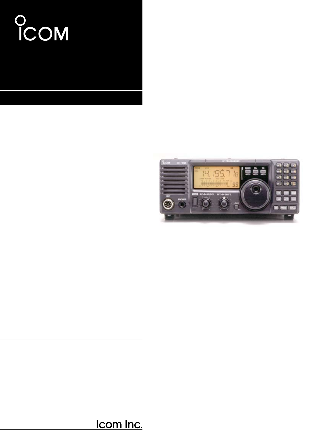
Многие производители любительской аппаратуры имеют в своём ассортименте несколько простых недорогих моделей трансиверов, ориентированных в первую очередь на радиолюбителей, делающих первые шаги в мир любительской радиосвязи. У ICOM такой моделью в линейке КВ трансиверов является IC-718.
При своих размерах 240мм Х 95 мм Х 239 мм IC-718 представляет собой достаточно компактный настольный трансивер, своим дизайном отдалённо смахивающий на военную связную аппаратуру. Большую часть передней панели трансивера занимают жидкокристаллический дисплей c подсветкой янтарного цвета, ручка настройки и громкоговоритель. Концентрические регуляторы AF (RF/SQL) и RIT (IF SHIFT) расположены прямо под дисплеем в центре лицевой панели трансивера. Наиболее часто используемые элементы управления MODE, FILTER и TS выполнены в виде кнопок, которые немного выступают над поверхностью лицевой панели, и расположены непосредственно над ручкой VFO. Большинство отавшихся кнопок, включая клавиатуру для прямого ввода частоты, занимают правую часть лицевой панели. Сюда же выведены 8-ми контактный разъём для подключения микрофона и 6.3 мм гнездо для наушников.
Задняя панель выглядит простенько. Помимо гнезда SO-239 для подключения антенны, стандартного 6-ти контактного разъёма для подключения блока питания трансивера, присутствуют разъёмы для управления внешним автоматическим антенным тюнером и подключения аксессуаров, а так же порты для управления трансивером при помощи компьютера и подключения внешнего усилителя мощности.
Максимальная выходная мощность IC-718 составляет 100 Вт в режимах SSB, CW, RTTY и 40 Вт в режиме AM. Выходная мощность трансивера плавно регулируется в диапазоне 5-100 Вт (2-40 Вт в режиме AM).
В меру интуитивно понятный
Если вы уже владели трансиверами ICOM, то разобраться с IC-718 даже без изучения руководства пользователя не составит особого труда. Подключение антенны и необходимых аксессуаров, а так же первичная настройка трансивера после первого включения не вызовет никаких затруднений. Там всё просто и доступно даже для не самых опытных пользователей. Для более детального изучения функциональных возможностей трансивера, вам всё-таки придётся потратить некоторое время и обратиться к руководству пользователя. В IC-718 доступно два типа меню — для быстрой и начальной установки параметров. В меню быстрой настройки доступно 13 опций — установка выходной мощности трансивера, трёхуровневая регулировка яркости дисплея, регулировка микрофонного усилителя, настройки VOX, а так же основные параметры режимов CW и RTTY.
В меню начальных установок доступны следующие опции: параметры индикатора уровня сигнала и выходной мощности, звуковая индикация нажатия клавиш, уровень громкости тона CW, скорость сканирования приёмника и условия возобновления сканирования, переназначение функций ручки регулировки RF/SQL, тип телеграфного манипулятора, а так же ряд настроек, связанных с внешними аксессуарами.
Все опции меню имеют 8-ми символьное буквенно-цифровое мнемоническое обозначение, так что вам не составит особого труда найти нужный пункт для изменения настроек трансивера.
Итак, IC-718 достаточно прост в работе и позволяет выйти в эфир даже без детального изучения документации.
Если же вы предпочитаете начинать знакомство с новым трансивером с чтения руководство пользователя, то тут вы тоже не будете разочарованы. Руководство очень хорошо организовано и структурировано, вся информация изложена последовательно, поэтому с его помощью очень просто изучать функционал трансивера. Кроме того, руководство содержит разворот с блок-схемами и принципиальными схемами трансивера.
Повседневная эксплуатация
Переключение диапазонов в IC-718 выполняются при помощи клавиш UP/DN. Однако, если вам больше нравится крутить ручку настройки, то тут поможет клавиша TS, предназначенная для выбора шага перестройки VFO. Таким образом вы можете довольно быстро перестраивать трансивер в широком диапазоне частот. Более того, если вращать ручку настройки быстро, то трансивер автоматически будет увеличивать шаг перестройки VFO.
Безусловно, трансивер позволяет сохранять до 101 выбранных частот в памяти, а затем, переключившись в канальный режим (клавиша CH), перебирать их последовательно клавишами UP/DN или перейти к нужной ячейке, набрав её номер на клавиатуре.
IC-718 поддерживает 2 VFO, что позволяет ему работать с разносом частот приёма и передачи. Эти параметры так же могут быть сохранены в памяти трансивера.
В IC-718 реализованы два режима сканирования. Один из них предназначен для сканирования частот, сохранённых в памяти трансивера. К сожалению, в этом режиме нет возможности исключить отдельные ячейки из процесса. Другой, программный поиск, предназначен для поиска сигналов в заданном интервале частот. Реальность такова, что многообразие сигналов, уровни которых могут значительно отличаться, а так же всевозможные случайные помехи, делают этот режим практически бесполезным, что в не меньшей степени справедливо и по отношению к другим, более дорогим трансиверам.
Цифровая радиосвязь
Работать цифровыми видами радиосвязи, такими как RTTY или PSK31, на IC-718 очень просто. Вход и выход аудио, а так же сигнальные линии для управления режимом приём-передача собраны в 13-ти контактном разъёме для подключения аксессуаров. Трансивер не перегревается при длительных включениях на передачу даже на максимальной мощности. Принудительный теплообмен обеспечивается внутренним вентилятором. Вентиляционные отвертия находятся на дне корпуса трансивера. Сам вентилятор шумит вполне умеренно.
IC-718 обладает превосходной температурной стабильностью частоты. Несмотря на это, в трансивер можно установить опциональный высокостабильный генератор. Для любителей FSK в разъёме для подлкючения аксессуаров есть соответствующая управляющая линия.
С PSK31 у IC-718 так же не возникает никаких трудностей. Даже при использовании самой обычной звуковой платы компьютера на выходе получается кристально чистый сигнал без каких-либо внеполосных излучений.
Единственная проблема первых выпусков IC-718 — это очень большое время переключения приём-передача, порядка 290 мс. Если для аналоговых видов модуляции, равно как и для отдельных цифровых видов связи это не принципиально, то для режимов, при которых происходит быстрый обмен короткими посылками (PACTOR, G-TOR, AMTOR, Clover), этот показатель является катастрофически недопустимым. Для таких видов связи крайне важно, чтобы трансивер после передачи блока информации практически моментально (не более 35 мс) переключался на приём и был готов принять данные. В противном случае он попросту будет терять начало каждого информационного сообщения и установить связь будет просто невозможно. Чтобы исправить эту проблему в ICOM отреагировали разработкой модификации трансивера. Если вам достался один из медленных экземпляров, то придётся поискать решение, которое снизит время переключения приём-передача до 25 мс.
Радиосвязь телеграфом
Телеграфистам IC-718 предоставляет стандартные функциональные возможности. Трансивер оснащён электронным ключом, скорость передачи которого регулируется в пределах от 6 до 60 слов в минуту. Длительность посылок и пауз так же можно отрегулировать на свой вкус. Частоту тона самоконтроля можно изменять в пределах от 300 до 900 Гц. Громкость этого сигнала так же регулируется в широких пределах. В трансивере предусмотрен режим инвертирования боковой полосы в телеграфном режиме для улучшения приёма сигналов корреспондентов в условиях помех от соседних станций.
Телеграфный манипулятор можно подключить к разъёму на задней панели трансивера или прямо в микрофонный разъём на лицевой панели. Как это сделать хорошо описано в руководстве пользователя. Так же в меню есть опция, позволяющая превратить клавиши UP/DN микрофона в телеграфный манипулятор. Несмотря на то, что использование микрофона в качестве телеграфного ключа для передачи читабельного кода задача не из простых для нетренированных рук, тем не менее эта функция может оказаться полезной в условиях, когда нормальный телеграфный манипулятор недоступен.
Режим полного дуплекса в IC-718 реализован, хоть и сопровождается довольно громкими щелчками реле коммутации приём-передача. В общем этот трансивер больше ориентирован на тех, кто проводит телеграфные связи не очень часто.
Полезные дополнения
IC-718 допускает установку одного дополнительного фильтра промежуточной частоты. Если вы работаете в эфире преимущественно телеграфом или радиотелетайпом, то 500 Гц фильтр будет неплохим дополнением для данного трансивера. Вся линейка доступных для данного трансивера фильтров включает фильтры 250 и 500 Гц для CW/RTTY, а так же 1.8, 2.8 и 3.3 кГц для SSB. Для амплитудной модуляции фильтров нет. Фильтры устанавливаются на плату трансивера при помощи пайки. Несмотря на то, что сам по себе процесс установки опционального фильтра ни у кого не должнен вызывать никаких сложностей, многие радиолюбители всё же предпочитают более гибкие решения, когда фильтр устанавливается в предусмотренный разъём без пайки, что в первую очередь позволяет быстро менять один фильтр на другой в зависимости от текущих нужд просто сняв крышку корпуса трансивера.
Трансивер оснащён подавителем импульсных помех, параметры которого можно плавно регулировать. Для этого достаточно несколько секунд подержать нажатой кнопку NB и при помощи ручки VFO установить требуемы уровень шумоподавления. В IC-718 этот фильтр весьма эффективно позволяет бороться с помехами от систем зажигания автомобилей.
В отличие от некоторых моделей трансиверов эконом-класс других производелей, в IC-718 нет встроенного антенного тюнера. Можно подключать только внешние.
IC-718 оснащён встроенным измерителем КСВ, что является хорошим дополнением в трансивере, который по своим размерам вполне годится для использования в качестве мобильного или походного аппарата.
Любителей работать телефоном трансивер порадует наличием системы VOX. Дополнительно в него можно установить модуль синтезатора речи UT-102, который предназначен для информирования о значении рабочей частоты и показаниях S-метра.
Ложечка дёгтя
Один из недостатков IC-718 — это отсутствие режима FM. Всё-таки FM достаточно широко распространён на 10-ти метровом диапазоне. При хорошем прохождении там всегда можно услышать станции, работающие в FM. Трансивер перекрывает FM-участок диапазона 10 м, поэтому наличие возможности слушать и проводить связи в режиме FM добавило бы этому трансиверу привлекательности среди потенциальных покупателей, хотя, возможно, и увеличило бы его конечную стоимость. В конце концов ICOM следовало бы рассмотреть такую возможность хотя бы с помощью опционального модуля.
Ещё одна проблема этого трансивера — фиксированная АРУ. В IC-718 полностью отсутсвует возможность регулировки времени срабатывания АРУ. Безусловно, никто и не ожидал увидеть в подобном трансивере плавную регулировку АРУ, но хотя бы на уровне быстро/медленно она должна быть, как весьма полезная функция, способная сделать приём определённых сигналов в определённых условиях более комфортным.
Заключение
Для присутсвия в эфире от случая к случаю вам вовсе не нужно тратить огромные деньги на аппаратуру. Дорогая аппаратура с множеством сервисных функций ориентирована в основном на заядлых радиоспортсменов и охотников за DX и большинству радиолюбителям многие из них могут вообще никогда не потребоваться. Если вы не из числа «профи», то всё что вам нужно — это простой недорогой трансивер, который позволяет выйти в эфир и наслаждаться любимым хобби. Этим требованиям IC-718 соответствует в полной мере.
INSTRUCTION MANUAL
HF ALL BAND TRANSCEIVER
i718

IMPORTANT
WORD
R WARNING
CAUTION
NOTE
DEFINITION
Personal injury, fire hazard or electric
shock may occur.
Inconvenience only.
No risk of personal injury, fire or
electric shock.
Equipment damage may occur.
READ T H I S INSTRUCTION M A N U A L
CAREFULLY before attempting to operate the
transceiver.
SAVE THIS INSTRUCTION MANUAL. This
manual contains important saf ety and ope rating
instructions for the IC-718.
PRECAUTIONS
R WARNING HIGH VOLTAGE! NEVER
attach an antenna or internal antenna connector
during transmission. This may result in an electric
shock or burn.
R NEVER apply AC to the [DC13.8V] jack on the
transceiver rear panel. This could cause a fire or ruin
the transceiver.
R NEVER apply more than 16 V DC, such as a 24
V battery, to the [DC13.8V] jack on the transceiver
rear pa nel . This co uld cau se a fire or ruin the
transceiver.
R NEVER let metal, wire or other objects touch
any internal part or connectors on the rear panel of
the transceiver. This may result in an electric shock.
NEVER expose the transceiver to rain, snow or any
liquids.
AVOID using or placing the transceiver in areas with
temperatures below –10°C (+14°F) or above +60°C
(+140°F). Be aware that temperatures on a vehicle’
s dashboard can exceed 80°C (+176°F), resulting in
permanent damage to the transceiver if left there for
extended periods.
AVOID placing the transceiver in excessively dusty
environments or in direct sunlight.
EXPLICIT DEFINITIONS
During mo bil e op eration, DO N OT o per ate the
transceiver without running the vehicle’s engine.
When transceiver power is ON and your vehicle’s
engine is OFF, the vehicle’s battery will soon become
exhausted.
Ma ke sure the transceiver power is OFF b efore
starting the vehicle. This will avoid possible damage
to the transceiver by ignition voltage spikes.
During maritime mo b i l e o p e r a tion, keep th e
transceiver and microphone as far away as possible
from the magnetic navigation compass to prevent
erroneous indications.
BE CAREFUL! The heatsink will become hot when
operati ng the transceiver con tinuo usly for lo ng
periods.
BE CAREFUL! If a linear amplifier is connected, set
the transceiver’s RF output power to less than the
linear amplifier’s maximum input level, otherwise, the
linear amplifier will be damaged.
Use Icom microphones only (supplied or optional).
Other manufacturer’s microphones have different
pin assignments, and connection to the IC-718 may
damage the transceiver.
AVOID placing the transceiver against walls or putting
anything on top of the transceiver. This will obstruct
heat dissipation.
i

TABLE OF CONTENTS
1
IMPORTANT …………………………………………………… i
EXPLICIT DEFINITIONS …………………………………… i
PRECAUTIONS ……………………………………………….. i
1 TABLE OF CONTENTS ……………………………….. 1
SUPPLIED ACCESSORIES ……………………………… 1
2 PANEL DESCRIPTION …………………………….. 2–8
n Front panel ………………………………………………. 2
n Function display ……………………………………….. 5
n Rear panel ……………………………………………….. 6
n Microphone (HM-36) …………………………………. 8
3 INSTALLATION AND CONNECTIONS …….. 9–14
n Unpacking ……………………………………………….. 9
n Selecting a location …………………………………… 9
n Grounding ……………………………………………….. 9
n Antenna connection ………………………………….. 9
n Required connections ……………………………… 10
n Advanced connections …………………………….. 11
n Power supply connections ……………………….. 12
n Liner amplifier connections ……………………….. 13
n External antenna tuners …………………………… 14
4 FREQUENCY SETTING ………………………… 15–19
n When first applying power ………………………… 15
n Initial setting …………………………………………… 15
n VFO description ……………………………………… 16
n Frequency setting ……………………………………. 17
n Dial lock function …………………………………….. 19
5 RECEIVE AND TRANSMIT ……………………. 20–34
n Mode selection ……………………………………….. 20
n Squelch and RF gain ……………………………….. 20
n Function for receive …………………………………. 21
n DSP function (option) ………………………………. 23
n Filter selection ………………………………………… 24
n Filter setting ……………………………………………. 25
n Function for transmit ……………………………….. 26
n Split frequency operation …………………………. 30
n SWR ……………………………………………………… 30
n Function for CW ……………………………………… 31
n Function for RTTY …………………………………… 33
6 MEMORY OPERATION ………………………… 35–38
n Memory channels ……………………………………. 35
n Memory channel selection ………………………… 35
n Memory channel programming ………………….. 36
n Frequency transferring …………………………….. 37
n Memory clearing ……………………………………… 38
7 SCANS ……………………………………………….. 39–40
n Scan types …………………………………………….. 39
n Preparation …………………………………………….. 39
n Programmed scan operation …………………….. 40
n Memory scan operation ……………………………. 40
8 SET MODE ………………………………………….. 41–47
n General …………………………………………………. 41
n Quick set mode items ………………………….. 42-43
n Initial set mode items ………………………….. 44-47
9 INSTALLATION AND CONNECTIONS …… 48–51
n Opening the transceiver’s case …………………. 48
n Optional bracket and carrying handle………….. 48
n CR-338 HIGH STABILITY CRYSTAL UNIT …….. 49
n UT-102 VOICE SYNTHESIZER UNIT ……………. 49
n UT-106 DSP RECEIVE UNIT ………………………. 50
n Optional IF filters …………………………………….. 50
n AT-180 internal switch description …………….. 51
10 MAINTENANCE …………………………………. 52–53
n Troubleshooting ……………………………………… 52
n Fuse replacement …………………………………… 53
n Resetting the CPU ………………………………….. 53
11 SPECIFICATIONS …………………………………… 54
12 OPTIONS ………………………………………….. 55–56
13 CONTROL COMMAND ………………………. 57–58
n Remote jack (CI-V) information …………………. 57
14 INTERNAL VIEWS …………………………………… 59
n Top view ………………………………………………… 59
n Bottom view ……………………………………………. 59
15 INSTALLATION NOTES …………………………… 60
n DECLARATION OF CONFORMITY …………… 61
SUPPLIED ACCESSORIES
The transceiver comes with the following accessories.
q DC power cable …………………………………………… 1
w Hand microphone (HM-36) …………………………… 1
e Fuse (FGB 20 A; for DC cable) ……………………… 1
r Fuse (FGB 4 A; internal use) ………………………… 1
Qty.
1
2
MIC
IC-71 8
PHONES
RF/SQL AF
SHIFT RIT
LOCK
MODE
FIL
TS
PWR
TUNER
COMP
P.AMP
NB
ATT
SET
CH
ENT
F-INP
V/M
1
MW
4
A=B
2
M-CL
5
SCN
8
ANF
0
NR
.
A/B
3
VOX
97
SPL
M V
6
Z DN
UP Y
Speaker Function Display
@1
@0
!9 !7
!5
!4
!6
!3
!2
!0!8!1
oi
uy
tre
w
q
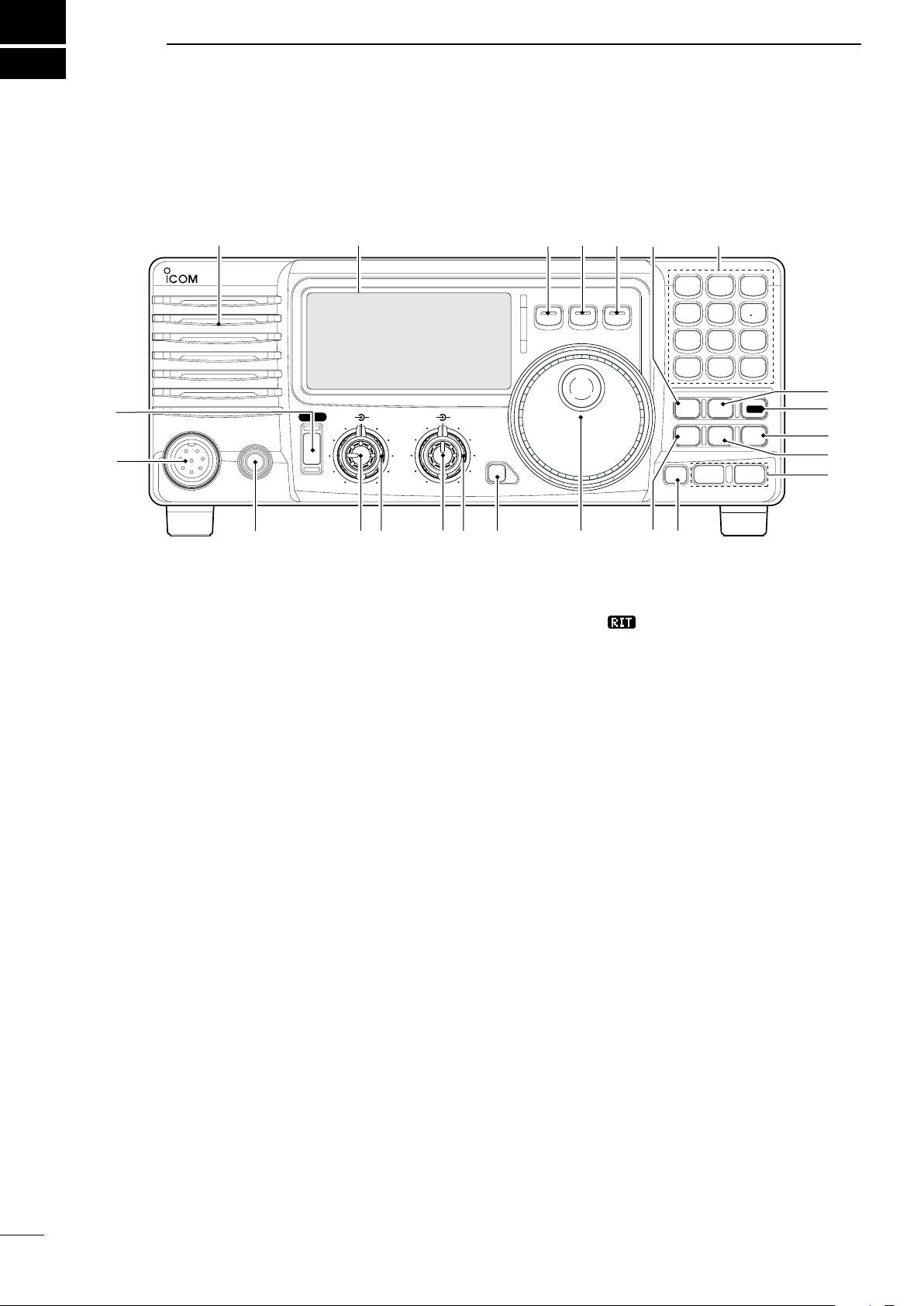
PANEL DESCRIPTION
n Front panel
or rotate the control counterclockwise to decrease the
q POWER SWITCH [PWR]
Push momentarily to turn power ON.
frequency. “
• The shift frequency range is ±1.2 kHz.
” appears on the display.
• Turn the optional DC power supply ON in advance.
Push for 1 sec. to turn power OFF.
While pushing and holding [SET], push [PWR]
to enter the initial set mode. (p. 41)
u IF SHIFT CONTROLS [SHIFT]
(Outer control; p.
21)
Shifts the center frequency of the receivers’s IF
pass-band.
w MICROPHONE CONNECTOR [MIC]
Accepts supplied or optional microphone.
• See p. 55 for appropriate microphones.
• See p. 8 for microphone connector information.
•
Rot ate th e co ntr ol c olckw ise to s hif t the c ent er
frequency higher, or rotate the control counterclockwise
to shift the center frequency lower.
i LOCK SWITCH [LOCK] (p. 19)
e HEADPHONE JACK [PHONES] (p. 11)
Accepts headphones (8
• When headphones are connected, the internal speaker
or connected external speaker does not function.
Ω).
r AF CONTROL [AF] (inner control)
Varies the audio output level from the speaker.
t RF GAIN/SQUELCH CONTROL [RF/SQL]
(outer control; pgs. 20, 44)
Adjusts the squelch threshold level. The squelch
removes noise output from the speaker (closed
condition) when no signal is received.
• The squelch is available for all modes.
• The control can be set as the squelch plus RF gain
controls or squelch control only (RF gain is fixed at
maximum) in initial set mode.
y RIT CONTROLS [RIT] (Inner control; p. 21)
Shifts the receive frequency without changing
the transmit frequency.
•
Rotate the control clockwise to incerase the frequency,
2
Push momentarily to turn the dial lock function ON
and OFF.
• The dial lock function electronically locks the main dial.
• When the optional UT-102
VOICE SYNTHESIZER UNIT is
installed (p. 49), push for 1 sec. to have the frequency,
etc. announced.
• UT-102 operation can be adjusted in initial set mode
(p. 46).
o MAIN DIAL
Changes the displayed frequency, selects quick/
initial set mode items, etc.
!0 PREAMP SWITCH [P.AMP] (p. 21)
Push momentarily to turn the preamp ON or OFF.
!1 CH SWITCH [CH] (p. 35)
Push momentarily to turn the memory channel
select function ON or OFF.
• [MEMO] blinks while memory channel select function is
turned on.

PANEL DESCRIPTION
2
• Push several times (or push and hold) [√ DN]/[UP ∫]
until desired memory channel appears.
• After pushing [F-INP/ENT], push desired memo ry
channel number from the keypad, then push [FINP/
ENT] again to select the memory channel directory.
• Push [CH] to exit the memory channel select function.
!2 MEMORY CHANNEL (BAND) UP/DOWN
SWITCHES [√ DN]/[UP ∫] (p. 35)
Push one or more times to select the memory
channel, while [MEMO] indicator is blinking.
Push to select a band.
Push to select the quick/initial set mode items
while quick/initial set mode is selected.
!3 ATTENUATOR SWITCH [ATT] (p. 22)
Push to toggle the 20 dB attenuator function ON
and OFF.
!4 TUNER SWITCH [TUNER] (pgs. 28, 29)
Push mo mentaril y to to ggle the a utomatic
antenna tuner function ON/OFF.
• An optional antenna tuner must be connected.
Push for 1 sec. to manually tune the tuner.
• An optional antenna tuner must be connected.
• When the tuner cannot tune the antenna, the tuning
circuit is bypassed automatically after 20 sec.
Push [NB] for 1 sec to enter the noise blanker
level setting condition.
!9 QUICK TUNING STEP SWITCH [TS] (pgs. 18, 19)
Selects a quick tuning step or turns the quick
tuning step OFF.
• While the quick tuning indicator () is displayed,
the frequency can be changed in kHz step.
While the quick tuning step is OFF, it turns the 1
Hz step ON and OFF when pushed for 1 sec.
• 1 Hz indication appears and the frequency can be
changed in 1 Hz steps.
While the kHz quick tuning step is selected, it enters
tuning step set mode when pushed for 1 sec.
@0 FILTER SWITCH [FIL] (p. 24)
Push momentarily to toggle between the pre-
programmed normal, wide and narrow IF filters
for the selected operating mode.
@1 MODE SWITCHES [LSB/USB]/[CW/CW-R]/
[RTTY/RTTY-R]/[AM] (p. 20)
Push to toggle an operating mode.
• Push[MODE] for 1 sec. during SSB mode to toggle
between LSB or USB.
• Push [MODE] for 2 sec. during CW or RTTY mode, to
toggle between CW and CW reverse or RTTY and
RTTY reverse. “ ” appears on the display.
!5 SET SWITCH [SET]
Push for 1 sec. to enter the quick set mode. (p.
41)
Pushing and h olding [SET], and then p ush
[POWER] to enter the initial set mode. (p. 41)
Push to toggle the meter function; (p. 26)
• PO: indicates the relative RF output power.
• ALC: Indicates ALC level.
• SWR: indicates the SWR over the transmission line.
!6 MIC COMPRESSOR SWITCH [COMP] (p. 27)
Toggles the Mic. compressor function ON and OFF.
!7 KEYPAD
The keypad can be used for several functions as
discribed below:
• [F-INP/ENT], keypad then [F-INP/ENT].
— Direct frequency input. (pgs. 4, 7)
•
[CH], [F-INP/ENT], keypad then [F-INP/ENT] then [V/M]
— Memory channel selection. (pgs. 4, 35)
• [V /M ], [A=B], [A/B], [M W] , [M-CL], [M
[S CA N] , [VOX], [N R] (option) and [ANF] (option)
switch. (p. 4)
≈V ], [SPL],
!8 NOISE BLANKER SWITCH [NB] (p. 22)
Toggles the noise blanker ON and OFF. The
noise blanker reduces pulse-type noise such as
that generated by automobile ignition systems.
This function is not effective against non pulsetype noise.
3
2
ENT
F-INP
V/M
1
MW
4
A=B
2
M=CL
5
SCN
8
ANF
0
NR
.
A/B
3
VOX
97
SPL
M V
6
#1
#3 #2
#0
@9
@8
@7
@6
@3
@4
@5
@2
MODE
FILTER
TS
TUNER
COMP
P.AMP
UP
NB
ATT
SET
CH
DN
ENT
F-INP
V/M
1
MW
4
A=B
2
M=CL
5
SCN
8
ANF
0
NR
.
A/B
3
VOX
97
SPL
M V
6
Z Y
PANEL DESCRIPTION
n Front panel (continued)
4
@2 VFO/MEMORY SWITCH/1 [V/M•1] (pgs. 16, 35)
Toggles the operating mod e b etween VFO
mode or memory mode when pushed.
@3 MEMORY WRITE SWITCH/4 [MW•4] (p. 36)
Stores the displayed frequency and operating
mode into the selected memory channel when
pushed for 1 sec.
@4 SPLIT SWITCH/7 [SPL•7] (p. 30)
Turns the split frequency operation ON or OFF
when pushed.
@5 NR SWITCH/. [NR• . ] (p. 23)
Toggles the optional noise reduction function ON
or OFF when pushed. Functions in all modes.
• An optional UT-106 DSP UNIT is required.
• [NR] appears on the display.
Enters noise reduction level set mode when
pushed for 1 sec.
@6 ANF SWITCH/0 [ANF•0] (p. 23)
Toggles the Automatic Notch Filter function ON or
OFF. Functions in SSB and AM modes.
• An optional UT-106 DSP UNIT is required.
• [ANF] appears on the display.
@7 FRQUENCY INPUT/ENTER SWITCH
[F-INP/ENT]
[F-INP/ENT], then keypad then [F-INP/ENT]
— Direct frequency input. (p. 17)
[CH] th en [F -IN P/E NT] , th en k eyp ad th en
[F-INP/ENT]. Push [CH].
— Direct memory number selection. (p. 35)
@8 SCAN SWITCH/8 [SCAN•8] (p. 39)
Push momentarily to start/stop the programmed
scan in VFO mode.
Push momentarily to start/stop the memory scan
in memory mode.
@9 VOX SWITCH/9 [VOX•9] (p. 27)
Turn the VOX function ON or OFF when pushed
in SSB modes.
#0 M≈V SWITCH/6 [MV•6] (p. 37)
Transfers the memory contents to VFO when
pushed for 1 sec.
#1 MEMORY CLEAR SWITCH/5 [M=CL•5] (p. 38)
Clears the selected readout memory c ha nn el
contents when pushed for 1 sec. in memory mode.
• [BLANK] appears above the memory channel number.
#2 VFO SELECT SWITCH/3 [A/B•3] (p. 16)
Tog gles between VF O A or VF O B in VF O
mode.
T o ggles b e t ween tra n smiss i on VFO and
reception VFO during split operation.
#3 VFO EQUALIZATION SWITCH/2 [A=B•2]
Equalize the frequency and operating mode of the
two VFO’s.
•
The VFO B frequency and operating mode are equalized
with the VFO A frequency and operating mode.
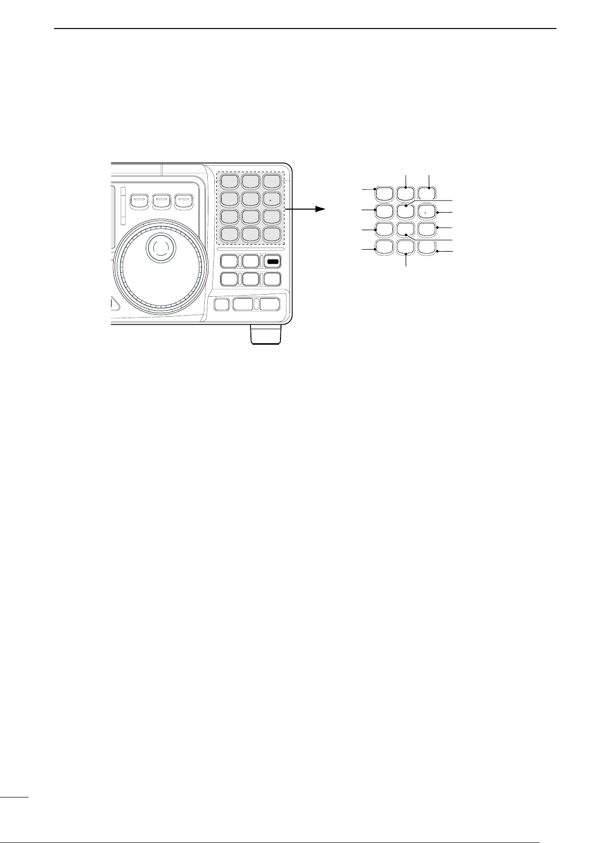
n Function display
!9
!6
!7
!8
o
!1!0
r
e
w
!4
!2
!5
!3
t
q
y
u
i
PANEL DESCRIPTION
2
q LOCK INDICATOR (p. 19)
Appears when the dial lock function is in use.
w RECEIVE INDICATOR
Appears while receiving a signal or when th e
squelch is open.
e TUNE INDICATOR
Appears while the automatic tuning function is
activated.
r TRANSMIT INDICATOR
Appears while transmitting.
t FUNCTION INDICATORS
“P.AMP” appears when antenna preamp is in
use.
“ATT” appears when the attenuator function is in
use.
“NB” appears when the Noise Blanker function
is turned ON.
“BK” appears when the semi break-in function is
selected in quick set mode.
“F-BK” appears when the full break-in function
activates in CW mode. (p. 31)
“ VOX ” ap pears wh en th e VO X function i s
selected in quick set mode.
“COM” appears when the speech compressor
activates in SSB mode.
“SCAN” appears when the scan function i s
activated.
• Flashes when scan is paused.
y DSP UNIT INDICATOR
Appears when an optional UT-106
installed.
DSP UNIT is
o SIGNAL/SQL/RF-GAIN METER
Functions as an S-meter while receiving.
Functions as a Power, ALC or SWR meter while
transmitting. (p. 26)
!0 VFO/MEMORY INDICATOR (p. 16)
“ VFO A ” or “ B” appear s whe n VFO mode is
selected.
“MEMO” appears when memory mode is selected.
!1 MEMORY CHANNEL NUMBER READOUT (p. 35)
Shows the selected memory channel number.
!2 BLANK INDICATOR (p. 38)
Shows that the displayed memory channel is not
programmed.
• This indicator appears both in VFO and memory mode.
!3 SPLIT INDICATORS (p. 30)
Appears when the split frequency operation is in
use.
!4 RIT INDICATOR (p. 21)
Appears when the RIT function is in use.
!5 FREQUENCY READOUT
Shows the operating frequency.
!6 REVERSE INDICATOR (p. 20)
Appears when the CW reverse or RTTY reverse
mode is selected.
!7
WIDE/NARROW FILTER INDICATORS (pgs. 24, 25)
“ ” appears when the wide IF filter is selected.
“ ” a ppears w hen the nar row IF filter is
selected.
u
AUTOMATIC NOTCH FILTER INDICATOR (p. 23)
Appears when the optional Automatic Notch Filter
function is in use.
i NOISE REDUCTION INDICATOR (p. 23)
A ppear s when the optio nal Noise Reduc tion
function is in use.
!8 PROGRAMMABLE TUNING STEP INDICATORS
Appears when the programmable tuning step is
selected.
!9 MODE INDICATORS (p. 20)
Indicates the selected operating mode.
5
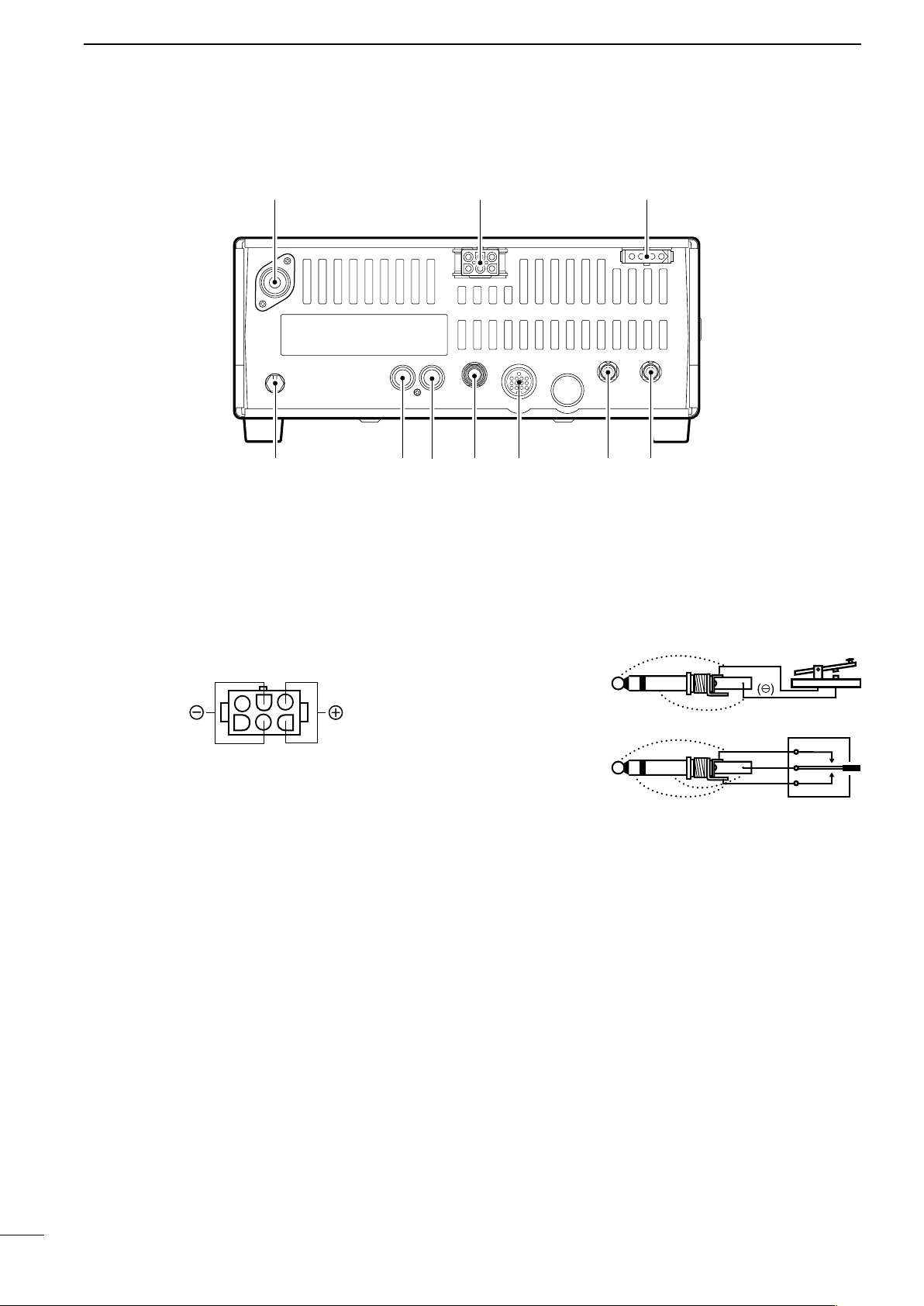
2
When connecting
a straight key
When connecting
a paddle
(dot)
(com)
(dash)
(⊕)
PANEL DESCRIPTION
n Rear panel
q ANTENNA TERMINAL [ANT] (p. 10)
Connects a 50
and a 50 Ω coaxial cable.
w DC POWER SOCKET [DC 13.8V] (p. 12)
Accepts 13.8V DC through the supplied DC power
cable.
e TUNER CONTROL SOCKET [TUNER] (p. 14)
Accepts the control cable from an optional AH-4
AUTOMATIC ANTENNA TUNER.
r CI-V REMOTE CONTROL JACK [REMOTE] (p. 57)
Designed for use with a personal computer for
remote operation of transceiver functions.
t EXTERNAL SPEAKER JACK [EXT SP] (p. 11)
Connects an 8
• When an external speaker is connected, the internal
y ACCESSORY SOCKET [ACC] (p. 7)
Enables connection to external equipment such as
an optional AT-180 AUTOMATIC ANTENNA TUNER,
a TNC for data communications or a liner amplifier,
etc.
Ω antenna with a PL-259 connector
Ω external speaker, if desired.
speaker does not function.
u ELECTRONIC KEYER JACK [KEY]
Accepts a paddle to activate the internal electronic
keyer.
• Selection between the internal electronic keyer and
straight key operation can be made in initial set mode.
i ALC INPUT JACK [ALC]
Connects to the ALC output jack of a non-Icom
linear amplifier.
o SEND CONTROL JACK [SEND] (p. 14)
G oes to g round while tr ansmitting to control
external equipments such as a liner amplifier.
• Max. control level: 16 V DC/2 A
!0 GROUND TERMINAL [GND] (p. 9)
Connects the terminal to ground.
6
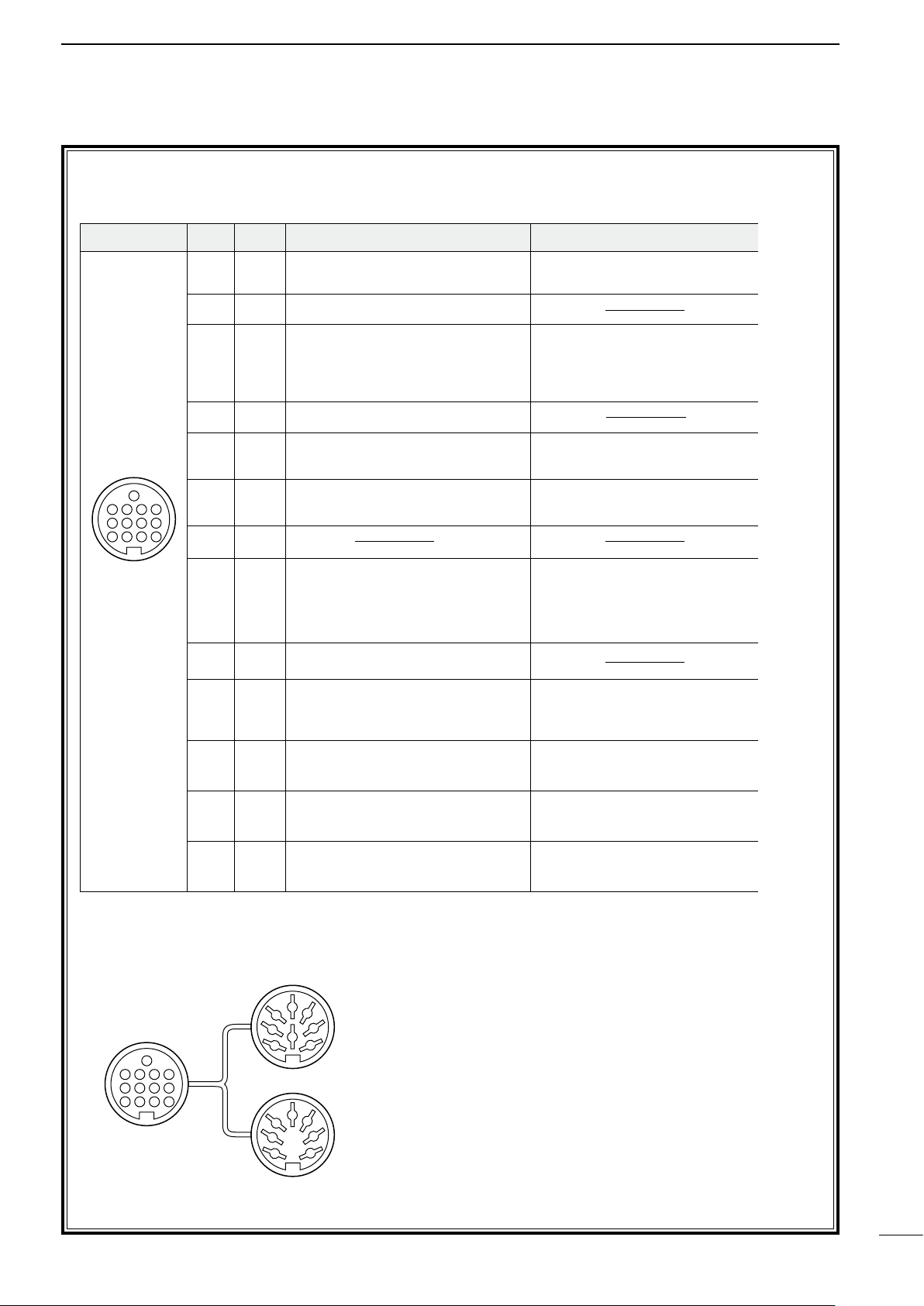
D ACC SOCKET INFORMATION
ACC PIN # NAME DESCRIPTION SPECIFICATIONS COLOR
1 8 V Regulated 8 V output.
Output voltage :8 V ±0.3 V
Output current : Less than 10 mA
brown
2 GND Connects to ground. red
3 SEND
Input/output pin.
Goes to ground when transmitting.
When grounded, transmits.
Ground level : –0.5 V to 0.8 V
Input current : Less than 20 mA orange
4 BDT Data line for the optional AT-180. yellow
5 BAND
Band voltage output.
(Varies with amateur band)
Output voltage : 0 to 8.0 V green
6 ALC ALC voltage input.
Control voltage : –4 to 0 V
Input impedance : More than 10 kΩ
blue
7 NC purple
8 13.8 V 13.8 V output when power is ON. Output current : Max. 1 A gray
9 TKEY Key line for the AT-180. white
10 FSKK
RTTY keying input.
Ground level : –0.5 to 0.8 V
Input current : Less than 10 mA
black
11 MOD Modulator input.
Input impedance :10 kΩ
Input level : Approx. 100 mV
rms
pink
12 AF
AF detector output.
Fixed, regardless of [AF] position.
Output impedance : 4.7 kΩ
Output level : 100 to 300 mV rms
light
blue
13 SQLS
Squelch output.
Goes to ground when squelch opens.
SQL open :Less than 0.3 V/5 mA
SQL closed :More than 6.0 V/100 µA
light
green
Rear panel
view
1 2 3 4
8765
9
10 11 12
13
ACC 1
ACC 2
q FSKK t AF
w GND y SQLS
e SEND u 13.8 V
r MOD i ALC
q 8 V t ALC
w GND y NC
e SEND u 13.8 V
r BAND
1122334
4
8877665
5
9
10 11 12
13
1
2
3
4
76
5
• ACC socket
PANEL DESCRIPTION
2
• When connecting the ACC conversion cable (OPC-599)
7
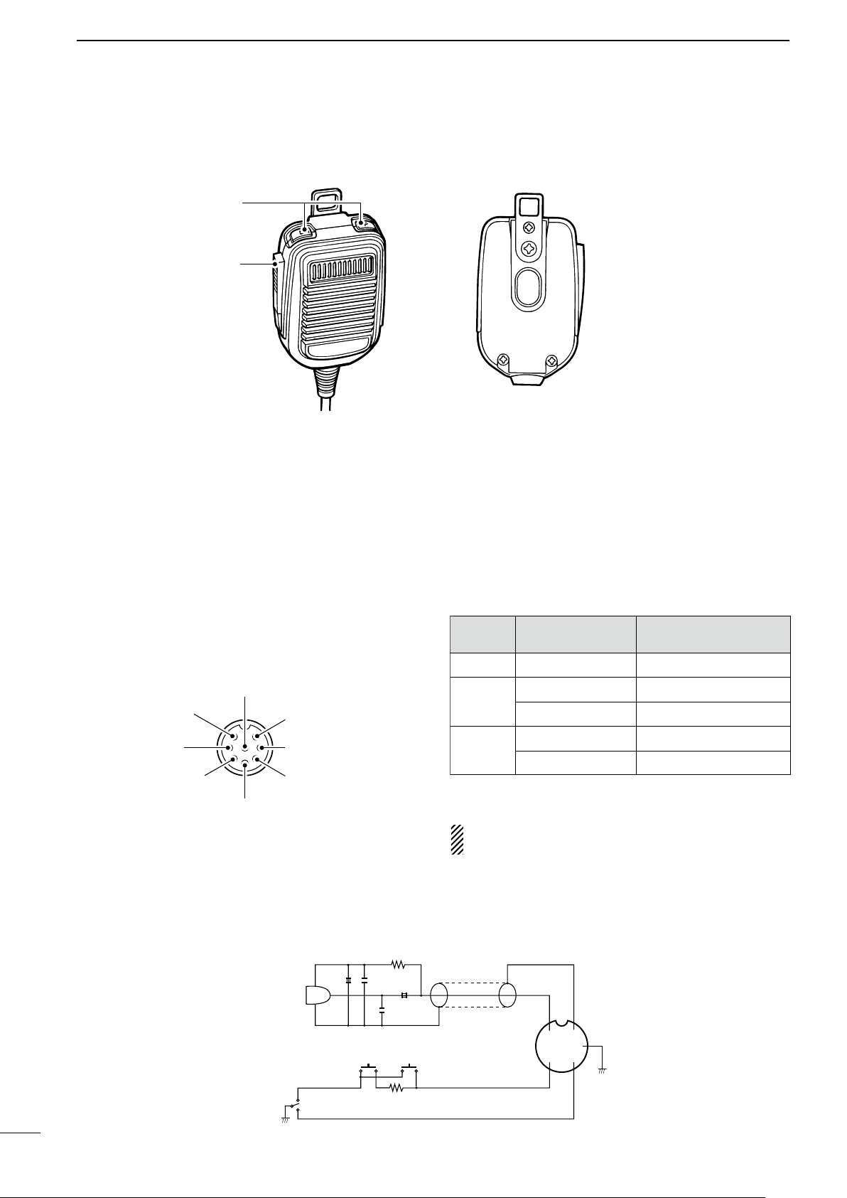
2
y GND (PTT ground)
t PTT
r Main readout squelch switch
q Microphone input
w +8 V DC output
e Frequency up/down
u GND
(Microphone ground)
i Main readout AF output
(varies with [AF]/[BAL])
Max. 10 mA
Ground
Ground through 470 Ω
“LOW” level
“HIGH” level
+8 V DC output
Frequency up
Frequency down
Squelch open
Squelch closed
[MIC]
PIN NO.
w
e
r
FUNCTION DESCRIPTION
+
+
q
w
ert
y
u
i
4700p
4700p
10µ
0.33µ
MICROPHONE
MIC
ELEMENT
2k
470
DOWN UP
PTT
RECEIVE
TRANSMIT
MICROPHONE CABLE MICROPHONE PLUG
PANEL DESCRIPTION
n Microphone (HM-36)
q UP/DOWN SWITCHES [UP]/[DN]
Change the selected readout frequency or memory
channel.
• Continuous pushing changes the frequency or memory
channel number continuously.
• Th e [UP] /[DN] sw itch c an simul ate a key p addle.
Preset in the CW PADDL in initial set mode. (p. 31)
• MICROPHONE CONNECTOR
(Front view)
w PTT SWITCH
Push and hold to transmit; release to receive.
CAUTION: DO NOT short pin 2 to ground as this
can damage the internal 8 V regulator.
• HM-36 SCHEMATIC DIAGRAM
8
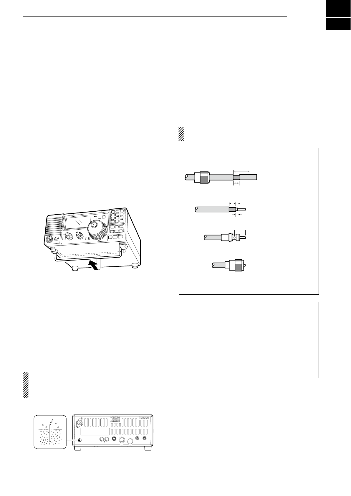
INSTALLATION AND CONNECTIONS
30 mm
10 mm (soft solder)
10 mm
1–2 mm
solder solder
Soft
solder
Coupling ring
Slide the coupling ring
down. Strip the cable
jacket and soft solder.
Slide the connector
body on and solder it.
Screw the coupling
ring onto the
connector body.
Strip the cable as
shown at left. Soft
solder the center
conductor.
q
w
e
r
3
n Unpacking
After unpacking, immediately report any damage to the
delivering carrier or dealer. Keep the shipping cartons.
For a des cri pti on and a di agra m of acce sso ry
equipment included with the IC-718, see ‘Supplied
accessories’ on p. 1 of this manual.
n Selecting a location
Se le ct a location for the transceiver that allows
adequate air circulation, free from extreme heat, cold,
or vibrations, and away from TV sets, TV antenna
elements, radios and other electro-magnetic sources.
The base of the transceiver has an adjustable stand
for desktop use. Set the stand to one of two angles
depending on your operating conditions.
n Antenna connection
For radio communications, the antenna is of critical
importance, along with output power and sensitivity.
Select antenna(s), such as a well-matche d 50 Ω
antenna, and feedline. 1. 5:1 or better of V olt age
Standing Wave Ratio (VSWR) is recommended for your
desired band. Of course, the transmission line should be
a coaxial cable.
CAUTIO N : Pr otec t your t ran s ceiv er fro m
lightning by using a lightning arrestor.
PL-259 CONNECTOR INSTALLATION EXAMPLE
n Grounding
To prevent electrical shock, television interference
(TV I), b road cast inte rfe renc e (BC I) and othe r
pro blem s, gr ound the t rans ceiv er th roug h the
GROUND terminal on the rear panel.
For best results, connect a heavy gauge wire or strap
to a long earth-sunk copper rod. Make the distance
between the [GND] terminal and ground as short as
possible.
R WARNING: NEVER connect th e
[GND] terminal to a gas or electric pipe, since the
connection could cause an explosion or electric
shock.
30 mm ≈ 9⁄8 in 10 mm ≈ 3⁄8 in 1–2 mm ≈ 1⁄16 in
Antenna SWR
Each antenna is tuned for a specified frequency
range and SWR may be increased out-of-range.
When the SWR is higher than approx. 2.0:1, the
transceiver’s po wer dro ps t o pr ote ct t he f ina l
transistor. In this case, an antenna tuner is useful
to match the transceiver and antenna. Low SWR
allows full power for transmitting even when using
the antenna tuner. The IC-718 has an SWR meter to
monitor the antenna SWR continuously
.
9
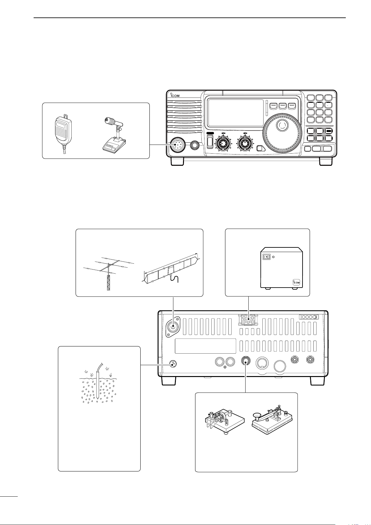
3
MIC
i718
PHONES
RF/SQL AF
SHIFT RIT
LOCK
MODE
FIL
TS
PWR
TUNER
Y
Z
COMP
P.AMP
UP
NB
ATT
SET
CH
DN
ENT
F-INP
V/M
1
MW
4
A=B
2
M-CL
5
SCN
8
ANF
0
NR
.
A/B
3
VOX
97
SPL
M V
6
MICROPHONES (p. 55)
SM-20HM-36
GROUND (p. 9)
Use the heaviest gauge wire
or strap available and make
the connection as short as
possible.
Grounding prevents electrical
shocks, TVI and other
problems.
ANTENNA (p. 56)
[Example]: 1.8–30 MHz bands
DC POWER SUPPLY
PS-85
CW KEY
A straight key can be used when the
internal electronic keyer is turned
OFF in “CW PADDL” in initial set
mode. (p. 31)
a
pp
ro
x.
24
.5
m
;
8
0
.3
ft
AH-710
INSTALLATION AND CONNECTIONS
n Required connections
• Front panel
• Rear panel
10
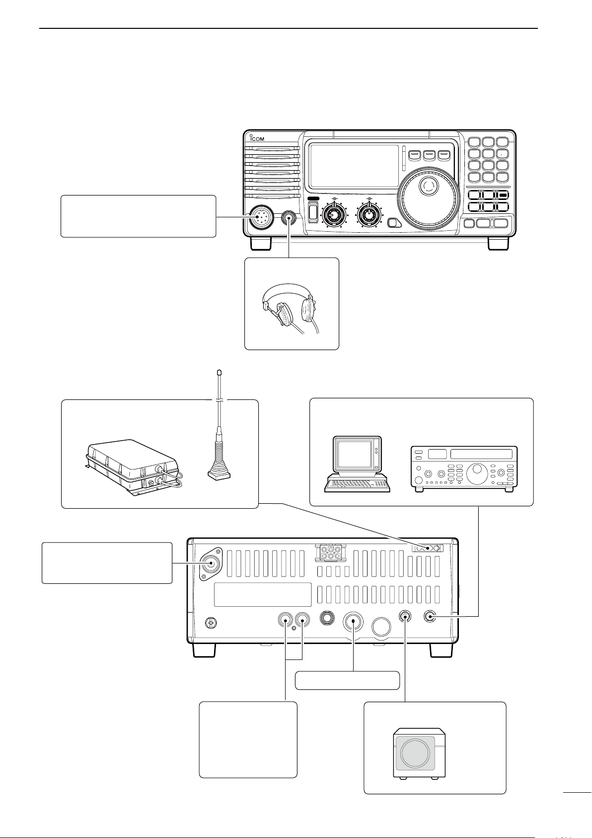
n Advanced connections
MIC
IC-718
PHONES
RF/SQL AF
SHIFT RIT
LOCK
MODE
FIL
TS
PWR
TUNER
Y
Z
COMP
P.AMP
UP
NB
ATT
SET
CH
DN
ENT
F-INP
V/M
1
MW
4
A=B
2
M-CL
5
SCN
8
ANF
0
NR
.
A/B
3
VOX
97
SPL
M V
6
MIC
The AFSK modulation signal can be
input from [MIC]. (p. 33)
HEADPHONES
ANTENNA (p. 13)
Connects a liner amprifier, etc.
[REMOTE] (p. 57)
Used for computer control and transceive operation.
[SEND], [ALC]
(p. 14)
Used for connecting a
non-Icom linear amplifier.
EXTERNAL SPEAKER (p. 55)
SP-21, etc
ACC SOCKETS (p. 7)
AH-4 (p. 55)
AH-2b
or long wire
with
• Front panel
INSTALLATION AND CONNECTIONS
3
• Rear panel
11
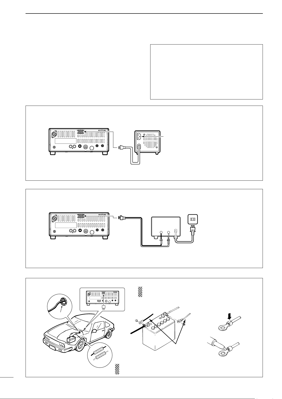
3
12 V
battery
Supplied
DC power cable
+ red
_ black
Crimp
Solder
Grommet
Fuses
1 2 3 4
8765
9
10 11 12
13
1 2 3 4
8765
9
10 11 12
13
PS-85
Connect to an AC outlet
using the supplied AC cable.
DC power cable
DC power
socket
DC power
socket
DC power supply
AC outlet
AC cable
20 A fuses
Supplied
DC power cable
13.8 V 20 A
_
+
black
red
+
_
1 2 3 4
8765
9
10 11 12
13
PS-85
Connect to an AC outlet
using the supplied AC cable.
DC power cable
DC power
socket
INSTALLATION AND CONNECTIONS
n Power supply connections
Use an optional PS-85 DC POWER SUPPLY when
operating the IC-718 with AC power. Refer to the
diagrams below.
CONNECTING PS-85 DC POWER SUPPLY
CAUTION: Before connecting the DC power
cable, check the following important items. Make
sure:
• The [POWER] switch is OFF.
• Output voltage of the power source is 12–15 V
when you use a non-Icom power supply.
• DC power cable polarity is correct.
Red : positive + terminal
Black : negative
_ terminal
CONNECTING NON-ICOM DC POWER SUPPLY
CONNECTING A VEHICLE BATTERY
NEVER connect to
a 24 V battery.
NOTE: Use terminals for
the cable connections.
12
NEVER connect to a battery without supplied DC fuses,
otherwise the fire hazard may occur.
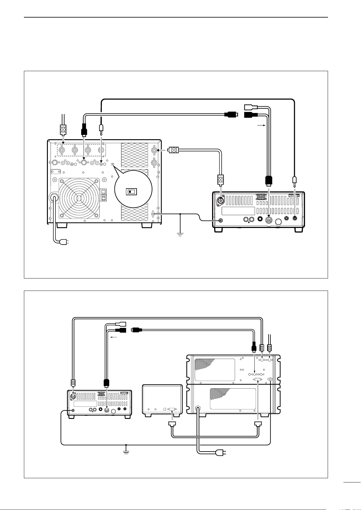
n Linear amplifier connections
1 2 3 4
8765
9
10 11 12
13
ANT
ACC-1
ACC
REMOTE
REMOTE
INPUT1
GND
GND
IC-PW1
IC-718
Ground
AC outlet
(Non-European versions : 100–120/220–240 V
European version : 230 V)
Coaxial cable
(supplied with the IC-PW1)
ACC cable
(supplied with the IC-PW1)
Remote control cable
(supplied with the IC-PW1)
To an
antenna
EXCITER
1 1&2
OPC-599 conversion cable
(option)
1 2 3 4
8765
9
1011 12
13
IC-718
Ground
IC-4KL
Remote
controller
Coaxial cable
(supplied with the IC-4KL)
ACC cable
(supplied with the IC-4KL)
ACC
IC-4KL
Remote control cable
(supplied with the IC-4KL)
AC outlet
(220–240 V)
To an
antenna
ANT
ACC
OPC-599 conversion cable
(option)
CONNECTING THE IC-PW1
INSTALLATION AND CONNECTIONS
3
CONNECTING THE IC-4KL
13
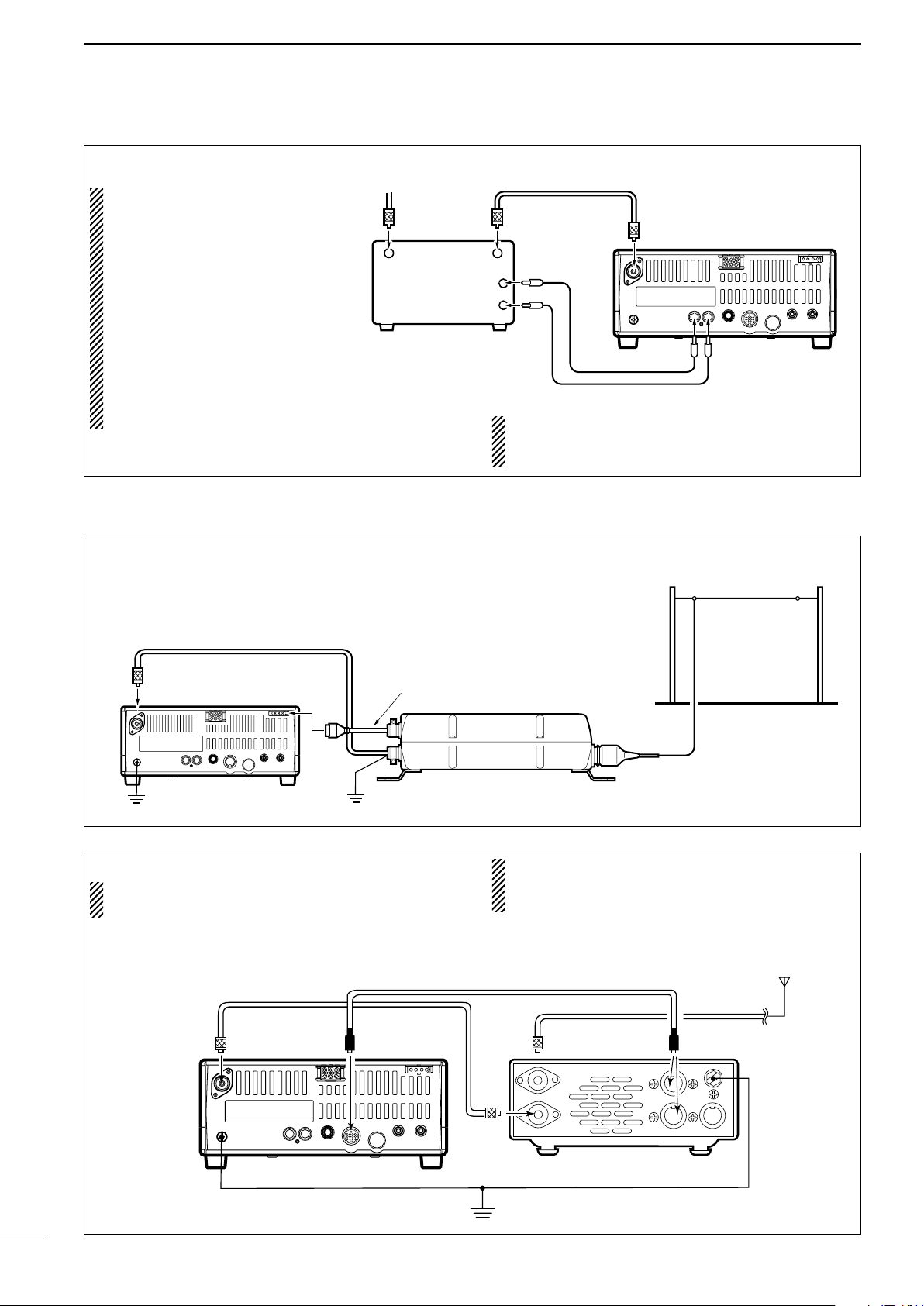
3
1 2 3 4
8765
9
10 11 12
13
RF OUTPUT RF INPUT
ALC
SEND
50 Ω coaxial cable
IC-718
ANT
ALC
SEND
To an
antenna
Non-Icom linear amplifier
Coaxial cable (from the AH-4)
Long wire or optional AH-2b
Ground
IC-718
AH-4
Control cable
Ground
1 2 3 4
8765
9
10 11 12
13
Ground
HF
antenna
[ANT]
[ACC]
[ACC]AT-180
ACC cable supplied with the AT-180
Coaxial cable supplied
with the AT-180
IC-718
one of two
connectors
INSTALLATION AND CONNECTIONS
CONNECTING A NON-ICOM LINER AMPLIFIER
R WARNING:
Set the transceiver output
power and linear amplifier
ALC output level referring
t o t h e li n e ar am p l if i e r
instruction manual.
The AL C input lev el must
be in the range 0 V to –4 V,
and the transceiver does not
accept positive voltage. Nonmatched ALC and RF power
settings could cause a fire or
ruin the linear amplifier.
n External antenna tuners
The specifications for the SEND relay are 16 V
DC 2 A. If this level is exceeded, a large external
relay must be used.
CONNECTING THE AH-4 (p. 29)
CONNECTING THE AT-180 (p. 28)
DO NOT! connect AT-180 and AH-4 at the same
time. Both tuners will not function correctly.
Turn the IC-718’s power OFF when connecting
the AT-180, otherwise, the CPU may malfunction
and the AT-180 may not function properly.
14
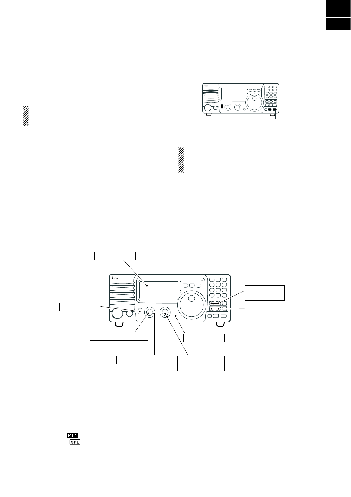
FREQUENCY SETTING
[METER]: Po
[LOCK]: OFF
[POWER]: OFF
[P.AMP], [ATT],:
OFF
[RIT]: Center
[IF SHIFT]: Center
[AF]: Max. CCW
[RF/SQL]: 12 o’clock
[NB], [COMP]:
OFF
n When first applying power (CPU resetting)
B e f o r e fi rst a p plyi n g powe r , mak e s ure a l l
connections required for your system are complete
by referring to Chapter 3. Then, reset the transceiver
using the following procedure.
Resetting CLEARS all programmed contents in
memory channels and returns programmed values
in quick/initial set mode to default values.
q Make sure the transceiver power is OFF.
w While pushing and holding [∫ UP] and [√ DN],
push [PWR] for 1 sec. to turn power ON.
• The internal CPU is reset.
• The transceiver displays its initial VFO frequencies
when resetting is complete.
e All quick/initial set mode settings are returned to
default values. (p. 41)
Under cooler temperatures, the LCD may appear
dark and unstable after turning power ON. This is
no rm al and does not indicate any equipment
malfunction.
4
n Initial settings
After resetting the tr an sc ei ve r, set controls and
switches as shown in the figure below.
CCW : counterclockwise
Turn power ON, then check the display. If any of the
following indicators appear, turn them OFF as follows:
• Quick tuning step indicator “Z” : Push [TS].
• 1 Hz frequency readout :
• RIT indicator “
• Split indicator “ ” : Push [SPL].
” : Center.
Push [TS] for 1 sec.
( wh il e quic k t uning
step is OFF)
15
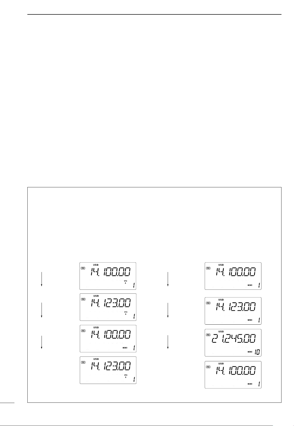
4
VFO is selected.
The frequency
is changed.
Memory mode
is selected.
VFO is selected
again.
Memory channel 1
is selected.
The frequency
is changed.
Another memory
channel is selected.
Memory channel 1
is selected again.
Changed frequency (14.123 MHz) does not appear and
memorized frequency (14.100 MHz) appears instead.
Changed frequency (14.123 MHz) appears.
FREQUENCY SETTING
n VFO description
VFO is an ab bre via tio n of Var iab le F req uen cy
Oscillator, and traditionally refers to an oscillator.
The IC-7 18 VFO ca n stor e a fre quenc y and a n
operating mode.
You can call up a desired frequency to the VFO with
the keypad or the memory transfer function (see p. 37).
You can also change the frequency with the tuning dial
and select the operating mode with the [MODE] switch
or call up previously accessed frequency and modes
with the band stacking register (p. 18).
The IC-718 has two VFOs, specially suited for split
frequency opration. The VFOs are called VFO A and
VFO B. You can call up the desired VFO.
• Differences between VFO mode and memory mode
VFO MODE
Each VFO shows a frequency and operating mode.
If the frequency or operating mode is changed, the
VFO automatically memorizes the new frequency or
new operating mode.
Whe n th e VF O is selected fr om a not her VFO
or me mory mode, the last-used fr equency and
operating mode for that VFO appears.
[EXAMPLE]
MEMORY MODE (pgs. 35–38)
Ea ch memory chann el shows a frequen cy and
operating mode like a VFO. Even if the frequency
or mode is changed, the memory channel does not
memorize the new frequency or operating mode.
When the memory channel is selected from another
memory channel or VFO mode, the m emorized
frequency and operating mode appear.
[EXAMPLE]
16
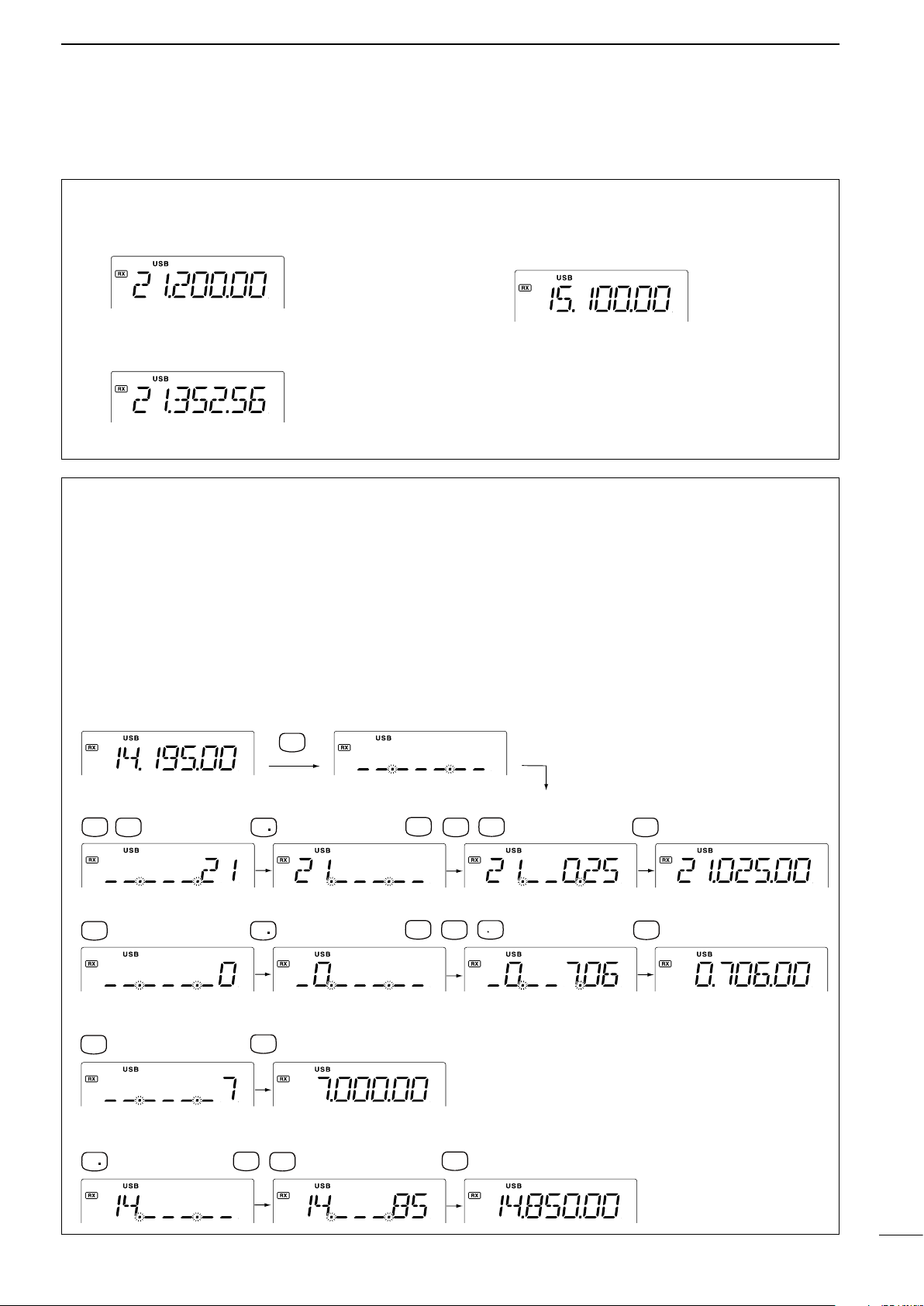
•To set to 21.025 MHz
•To set to 706 KHz (0.706 MHz)
•To set to 7 MHz
•To change 14.195 to 14.850 MHz
•Start
ENT
F-INP
V/M
1
NR
ANF
0
A=B
2
M=CL
5
ENT
F-INP
A=B
2
NR
7
SPL
ANF
0
M V
6
ENT
F-INP
ANF
0
ENT
F-INP
7
SPL
ENT
F-INP
SCN
8
M=CL
5
NR
n Frequency setting
FREQUENCY SETTING
4
D Using the tuning dial
q Push [∫ UP] or [√ DN] one or more times to
select the desired ham band.
w Select the desired operating mode with the mode
switch. (p. 20).
e Rotate the tuning dial to set the desired frequency
D Direct frequency entry with keypad
The transceiver has a keypad for direct frequency
entry as described below.
q Push [F-INP/ENT], then push the numeral keys
on the keypad to enter the MHz digits for the
desired frequency.
• If a key is mistakenly pushed, push [SET] (or any key
except keypad) and start again from the beginning.
• When entering the same MHz digits as the displayed
frequency, this step can be skipped.
[EXAMPLE]
• For general coverage receiver use
The IC-718 has a general coverage receiver band.
q Push [∫ UP] or [√ DN] one or more times to
select the general coverage receiver band.
Note: Even if you select the ham band, you can set the
transceiver to the general coverage frequency. When
the displayed frequency exits the transmit frequency
range (ham band), a band edge beep may be emitted
(depends on initial set mode programming).
w Push [•] on the keypad.
e Push the numeral keys to enter the frequency
digits below 1 MHz.
• If a key is mistakenly pushed, push [SET] (or any key
except keypad) and start again from the beginning.
r Push [F-INP/ENT] to set the input frequency.
•
When pushing [F- INP/ENT] after entering the MHz
digits, zeros are automatically entered for the kHz digits.
17
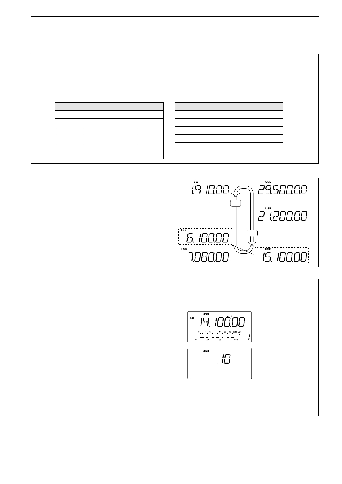
4
Programmable tuning
step indicator
10 KHz tuning steps is
selected.
DN
UP
General (new)
General (old)
Y
Z
BAND BAND BAND
1.9 MHz
1.91000 MHz CW
3.5 MHz 3.55000 MHz LSB
7 MHz
7.05000 MHz LSB
10 MHz 10.12000 MHz CW
14 MHz 14.10000 MHz USB
General 15.10000 MHz USB
BAND BAND BAND
18 MHz
18.10000 MHz USB
21 MHz 21.20000 MHz USB
24 MHz
24.95000 MHz
USB
28 MHz 28.50000 MHz USB
29 MHz 29.50000 MHz USB
FREQUENCY SETTING
D Band stacking resister
The band stacking register automatically stores the
last frequency and mode used for each band. This
is convenient for contest operation, etc. The tables
below shows the band stacking register default
settings for each band.
D Band selection
All HF ham bands and a general coverage receiver
band are included in the IC-718.
Push [∫ UP]/[√ DN] to select the desired band.
• Pushing [∫ UP]/[√ DN] continuously scrolls through the
available bands.
Note: For example, if 6.10000 MHz is resistered as
the General coverage frequency, then the General
coverage band automatically positions itself between
3.5 MHz and 7 MHz band.
D Programmable tuning steps
Programmable tuning steps are available to suit your
operating requirements.
These tuning steps are:
• Selectable from 0.1, 1, 5, 9, 10, 100 kHz
q
Push [TS], the programmable tuning step indicator,
“,” then appears above the 1 kHz.
• Ro ta ting th e tun in g dial changes the frequency
according to the set tuning step.
w Push [TS] for 2 sec. while the programmable
tuning step indicator appears to enter the tuning
step set mode.
e Rotate the tuning dial to set the desired tuning
step.
r Push [TS] to exit the tuning step set mode.
t Rotate the tuning dial to change the frequency
according to the set tuning step.
18
Loading…