
Displayed below is the user manual for NETYS PR RT 3300VA by Socomec which is a product in the Uninterruptible Power Supplies (UPSs) category.
This manual has pages.

NETYS PR RT
1700-3300 VA
安装及操作手册 CN
Installations- und bedienungsanleitung DE
Manual de instalación y uso ES
Manuel d’installation et d’utilisation FR
Installation and operating manual GB
Manuale di installazione e uso IT
Installatie– en bedieningshandleiding NL
Dokumentacja Techniczno-Ruchowa PL
Manual de instalação e funcionamento PT
Manual de instalare şi utilizare RO
Руководство по установке и эксплуатации RU
Navodila za priključitev in uporabo SI
Kurulum ve kullanım kılavuzu TR

2NETYS PR RT — Ref.: IOMNETPRXX03-GB 02
This SOCOMEC UPS appliance is guaranteed against manufacturing and material defects for a period of 12 months from the
date of purchase (local warranty conditions are applicable in addition to the general conditions). This warranty certificate should
NOT be e-mailed, but kept by the customer along with proof of purchase, for use in the event of a claim being made for repairs or
replacement under warranty.
The warranty period commences on the date the new product was purchased by the end user at an authorised showroom (reference
details are shown on the receipt).
Return-to-base warranty is provided: components and labour for repairs supplied free of charge, any products to be replaced must
be returned to SOCOMEC UPS or authorised service centres, at the customer’s own risk and expense.
The warranty is recognized within national territory. If the UPS is exported out of national territory, the warranty shall be limited to the
cover of the parts used to repair the fault.
To claim service under the warranty please observe the following:
• The product must be returned in the original packing. Any damage caused during shipping in packaging other than the original
will not be covered by the warranty;
• The product must be accompanied by proof of purchase such as an invoice or receipt indicating the date of purchase and
product ID information (model, serial numer). The sender must also attach the reference number issued to authorise the return
of the product, together with a detailed description of the defect. If any of this information is missing the warranty will be invalid.
The authorisation number is issued by service centres over the telephone on receiving information on the malfunction in question;
• If it is not possible to provide proof of purchase the serial number and date of manufacture will be used to calculate the probable
expiry date of the warranty; this could result in a reduction of the original warranty period.
The warranty on the product does not cover damage caused by carelessness (improper use: wrong input power, explosions,
excessive humidity, temperature, poor ventilation, etc.), tampering or any unauthorised repair work.
During the warranty period, SOCOMEC UPS reserves the right to decide whether the product should be repaired, or whether to
replace defective parts with new parts, or used parts that are equivalent to new parts in terms of functionality and performance.
In the case of batteries, warranty is valid only if the battery has been recharged regularly in accordance with the manufacturer’s
instructions. On purchasing the product it is advisable to check that the next recharge date indicated on the packaging has not expired.
Battery
• Batteries are treated as consumable parts and warranty only covers manufacturing defects.
• Batteries must be stored in compliance with Supplier recommendations.
• Warranty is valid only if the battery has been recharged regularly in accordance with the manufacturer’s instructions. On purchasing
the product it is advisable to check that the next recharge date indicated on the packaging has not expired.
Optionals
A 12-month return-to-base warranty is provided on optionals.
Software products
Software products are guaranteed for 90 days. The software is guaranteed to work as indicated in the manual accompanying
the product. Hardware media or accessories (e.g. diskettes, cables, etc.) used with appliances are guaranteed free of material or
manufacturing defects under normal conditions of use for a period of 12 months from the date of purchase.
SOCOMEC UPS will not be responsible for damages (including loss of income, interruption of business activity, loss of information
or other financial losses, of any nature) arising from the use of the product.
These conditions are subject to Italian law. Disputes shall come under the jurisdiction of Court of Vicenza.
WARRANTY CERTIFICATE AND CONDITIONS
SOCOMEC UPS retains the full and exclusive ownership rights over this document. Only a personal right to utilize the document
for the application indicated by SOCOMEC UPS is granted to the recipient of such document. All reproduction, modification, disse-
mination of this document whether in part or whole and by any manner are expressly prohibited except upon Socomec’s express
prior written consent.
This document is not a specification. SOCOMEC UPS reserves the right to make any changes to data without prior notice.

3
NETYS PR RT — Ref.: IOMNETPRXX03-GB 02
CONTENTS
ENGLISH
1. SAFETY STANDARDS . . . . . . . . . . . . . . . . . . . . . . . . . . . . . . . . . . . . . . . . . . . . . . . . . . . . . . 4
1.1 IMPORTANT . . . . . . . . . . . . . . . . . . . . . . . . . . . . . . . . . . . . . . . . . . . . . . . . . . 4
1.2
DESCRIPTION OF THE SYMBOLS USED ON LABELS ATTACHED TO THE UNIT
. 5
2. INSTALLATION . . . . . . . . . . . . . . . . . . . . . . . . . . . . . . . . . . . . . . . . . . . . . . . . . . . . . . . . . . . 6
2.1 ENVIRONMENTAL REQUIREMENTS FOR INSTALLATION . . . . . . . . . . . . . . . 6
2.2 VERTICAL INSTALLATION . . . . . . . . . . . . . . . . . . . . . . . . . . . . . . . . . . . . . . . 7
2.3 HORIZONTAL INSTALLATION ON RACK . . . . . . . . . . . . . . . . . . . . . . . . . . . . 9
3. REAR VIEW . . . . . . . . . . . . . . . . . . . . . . . . . . . . . . . . . . . . . . . . . . . . . . . . . . . . . . . . . . . . . 12
4. CONNECTIONS . . . . . . . . . . . . . . . . . . . . . . . . . . . . . . . . . . . . . . . . . . . . . . . . . . . . . . . . . . 13
5. CONNECTION OF BATTERY EXTENSION . . . . . . . . . . . . . . . . . . . . . . . . . . . . . . . . . . . . . . 14
5.1 SAFETY WARNINGS . . . . . . . . . . . . . . . . . . . . . . . . . . . . . . . . . . . . . . . . . . . 14
5.2 CONNECTION OF BATTERY EXTENSION . . . . . . . . . . . . . . . . . . . . . . . . . . . 14
6. MIMIC PANEL . . . . . . . . . . . . . . . . . . . . . . . . . . . . . . . . . . . . . . . . . . . . . . . . . . . . . . . . . . . 16
7. OPERATING MODES . . . . . . . . . . . . . . . . . . . . . . . . . . . . . . . . . . . . . . . . . . . . . . . . . . . . . . 17
7.1 BATTERY RECHARGING. . . . . . . . . . . . . . . . . . . . . . . . . . . . . . . . . . . . . . . . 17
7.2 SWITCHING THE NETYS PR ON AND OFF . . . . . . . . . . . . . . . . . . . . . . . . . 17
7.3 SETTING MENU . . . . . . . . . . . . . . . . . . . . . . . . . . . . . . . . . . . . . . . . . . . . . . 19
8. VISUAL AND AUDIBLE WARNING SIGNALS . . . . . . . . . . . . . . . . . . . . . . . . . . . . . . . . . . . . 20
8.1 ALARM INDICATION . . . . . . . . . . . . . . . . . . . . . . . . . . . . . . . . . . . . . . . . . . . 20
9. COMMUNICATION . . . . . . . . . . . . . . . . . . . . . . . . . . . . . . . . . . . . . . . . . . . . . . . . . . . . . . . . 21
9.2 USB INTERFACE . . . . . . . . . . . . . . . . . . . . . . . . . . . . . . . . . . . . . . . . . . . . . . 21
9.3 RS232 INTERFACE (J-BUS/MODBUS) . . . . . . . . . . . . . . . . . . . . . . . . . . . . . 21
9.4 WEB/SNMP CARD (OPTION) . . . . . . . . . . . . . . . . . . . . . . . . . . . . . . . . . . . . 21
10. MAINTENANCE . . . . . . . . . . . . . . . . . . . . . . . . . . . . . . . . . . . . . . . . . . . . . . . . . . . . . . . . . 22
10.1 MINOR TROUBLESHOOTING . . . . . . . . . . . . . . . . . . . . . . . . . . . . . . . . . . . 22
11. TECHNICAL SPECIFICATIONS . . . . . . . . . . . . . . . . . . . . . . . . . . . . . . . . . . . . . . . . . . . . . 23

4NETYS PR RT — Ref.: IOMNETPRXX03-GB 02
1. SAFETY STANDARDS
1.1 IMPORTANT
This manual should be kept carefully in a safe place near the UPS, so that it can be consulted by the operator at any time for any
information that may be needed regarding correct use of the unit. Read the manual carefully before connecting the unit to the a.c.
mains supply and to the downstream appliances. Before the UPS NETYS PR is put into commission, the user must be perfectly
familiar with its operation, with the position of all the controls and with the technical and functional characteristics of the unit, so as
to ensure there will be no risk to any persons or to the appliance itself.
• Before being started up, the unit must be equipotentially bonded, in accordance with current safety regulations. The earth
wire of the UPS must then be connected to an efficient earth system.
• If the earth connection is not made, the appliances connected to the UPS will not be equipotentially bonded. In this situa-
tion, the manufacturer declines all liability for any damage or accidents that could derive from failure to observe the requirements.
• Should a power outage occur (UPS in stand-alone mode), do not disconnect the power cord from the mains, as this will
break the earth connection to bonded appliances.
• All subsequent maintenance operations must be entrusted only to authorized service engineers. The UPS generates high
internal voltages that could be hazardous for a maintenance operative not in possession of the appropriate skills and training for
this type of work.
• If a hazard situation should arise at any moment when the UPS is in use, isolate the unit from the power supply (by operating
a switch at the upstream PDU if possible) and switch the appliance off completely by running the shutdown procedure.
• The UPS houses a source of electrical energy, namely its batteries. The output of the UPS may be under power even
when the appliance is not connected to the a.c. mains supply.
• Never force, break or attempt to open the batteries. These batteries are sealed, maintenance-free components contai-
ning substances that are harmful to health and a source of environmental pollution. If liquid can be seen leaking from the
battery, or a white powdery residue is noticeable, do not switch the UPS on.
• Avoid exposing the UPS to contact with water or any liquids generally. Do not insert foreign objects into the cabinet.
• Danger of explosion if the batteries are replaced with others of the wrong type.
• Replaced batteries must be disposed of at authorised waste disposal centres.
It is very dangerous to touch any part of the batteries as there is no isolation between the batteries and the mains
power source.
CAUTION!
A battery can present a risk of electrical shock and high short circuit current.
• If the appliance is to be scrapped, it must be entrusted exclusively to a specialist waste disposal company. These companies
will split up and dispose of the various components in accordance with statutory regulations in the country of purchase.
• Since the power cord of the UPS functions as an isolating device, ensure ready access to the mains power socket where the UPS
is connected, and/or to the rear panel of the UPS, so the unit can be easily unplugged.
• The UPS generates a leakage current of approximately 3 mA. To guarantee the maximum leakage current of 3.5 mA, make certain
that the leakage current generated by the load is no greater than 0.5 mA. Should the leakage current from the load exceed this
limit, instruct a skilled engineer to install an industrial type connection (to IEC 309 standard) between the UPS and the a.c. mains
supply, sized to handle a current compatible with the rating of the appliance.
• Use the UPS in accordance with the technical specifications indicated in this manual (chapter 11).
• To meet the operating requirements for the Emergency Switch Device (ESD), a specific RJ11 input with remote ESD/EPO function
is available.
• In the event that the equipment has no automatic backfeed protection contactor device, make certain that:
— the user/installer attaches warning labels to all mains isolating switches located remotely from the area where the UPS is sited, in
order to inform service personnel that the circuit is connected to a UPS.
— an external isolating device is installed, as indicated in figure 1-1.
• The product you have chosen is designed for commercial and industrial use only.
• The product you have selected, given the specified conditions of use, capacity and performance limits, is designed exclusively for
commercial and industrial service. The use of the product in “critical applications” could require compliance with statutory regula-
tions and standards, or with specific local bylaws, or adaptation to SOCOMEC UPS recommendations. For this type of use, in any
event, it is advisable to contact SOCOMEC UPS beforehand for confirmation regarding the capacity of products to meet required
levels of safety, performance and reliability. The expression “critical applications” covers, in particular, life support systems, medical
applications, commercial transport, nuclear facilities or any other systems where failure of the product might on occasion cause
serious damage to persons or property.
5
ENGLISH
NETYS PR RT — Ref.: IOMNETPRXX03-GB 02
1. SAFETY STANDARDS
WARNING!
This is a product for commercial and industrial application in the second environment – installation restrictions or
additional measures may be needed to prevent disturbances.
CAUTION IF DAMAGED.
BATTERIES, NON SPILLABLE.
Packages, crushed, punctured, or torn such that contents are revealed must be set aside in an
isolated area and inspected by a qualified person. If the package is deemed to be not shippable, the
contents must be promptly collected, segregated, and either the consignor or consignee contacted.
All packaging material must be recycled in compliance with the laws in force in the country where the system is installed.
1.2
DESCRIPTION OF THE SYMBOLS USED ON LABELS ATTACHED TO THE UNIT
All precautions and warnings on labels and plates on the inside and outside the equipment should be observed.
DANGER! HIGH VOLTAGE (BLACK/YELLOW)
GROUND TERMINAL
READ THE USER MANUAL BEFORE USING THE UNIT

6NETYS PR RT — Ref.: IOMNETPRXX03-GB 02
2. INSTALLATION
2.1 ENVIRONMENTAL REQUIREMENTS FOR INSTALLATION
Consult the following check list when installing the UPS:
• NETYS PR units are designed for use in enclosed environments.
• Position the UPS on a flat and stable surface in a properly ventilated room, well away from heat sources and avoiding direct
exposure to sunlight.
•
Ambient temperature should be kept between 0 °C and 40 °C, and relative humidity below 80% (without condensation);
the optimum temperature in terms of maximising battery lifetime is 15÷20 °C.
• Check that the UPS will not be installed in a dusty environment.
•
Be certain that a clearance of at least 20 cm is left on all sides of the unit to ensure adequate ventilation and provide access to the rear panel.
• Take care not to stand the UPS or any other heavy object on cables.
• Check that the operating voltage and frequency settings are correct for the mains power supply at the installation site. Details for
the UPS will be found on the data plate attached to the rear panel.
• When carrying out the RS232 serial connection, use only the cables and accessories supplied or specified by the manufacturer.
• When the UPS is first used, it is advisable to leave the battery on charge for a minimum of 8 hours.
PRECAUTIONS IN THE EVENT OF DAMAGE
DO NOT TURN THE BATTERIES OVER
Packaging materials that have been broken, punctured or torn in such a way as to reveal the contents must be
kept separate in a secure area, and inspected by skilled staff. Any packaging considered unsuitable for shipment
of the contents must be set aside immediately and kept secure, and the sender or recipient contacted.
7
ENGLISH
NETYS PR RT — Ref.: IOMNETPRXX03-GB 02
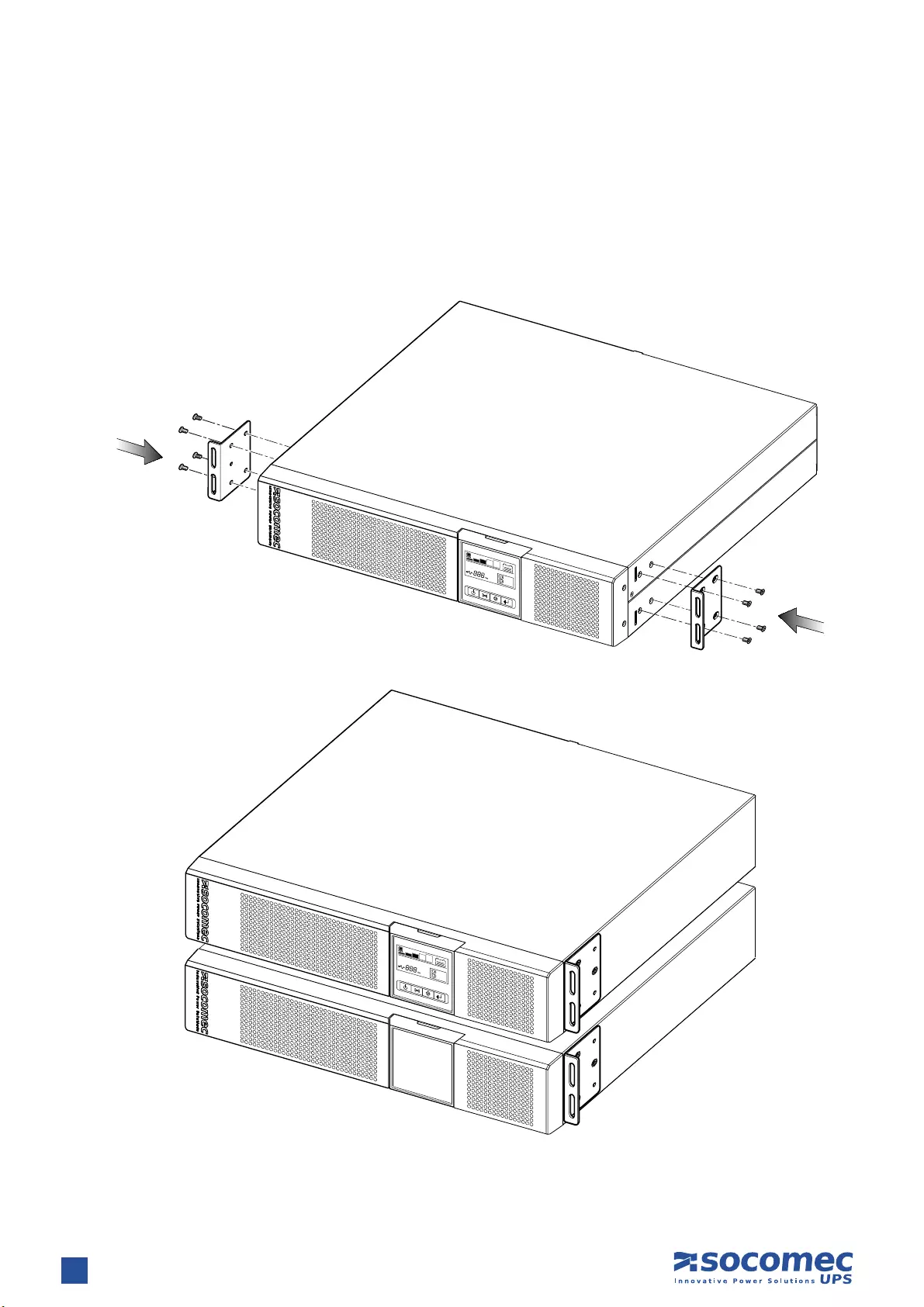
2. INSTALLATION
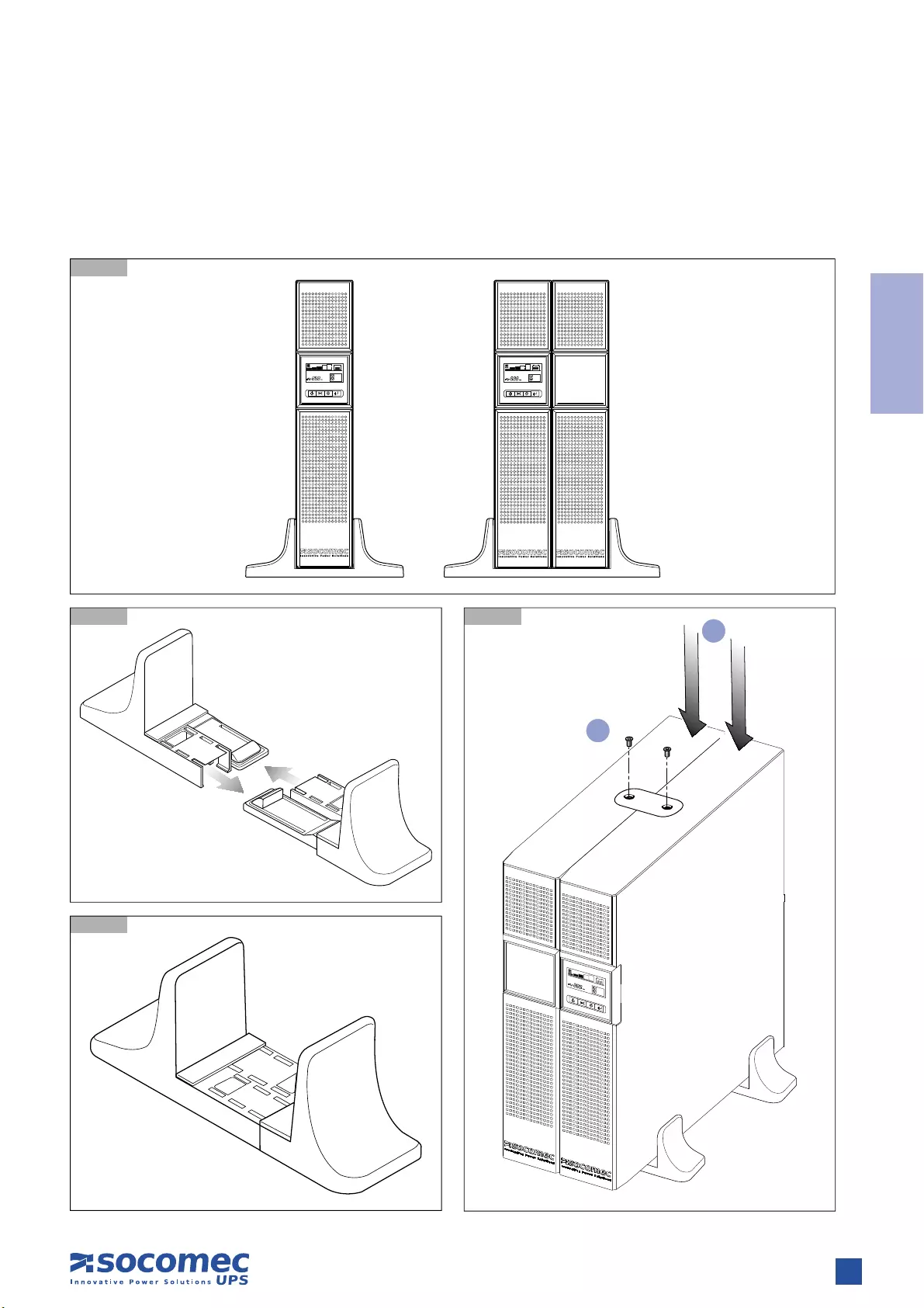
2.2 VERTICAL INSTALLATION
2.2.1 UPS Installation
2.2.1-1
2.2.1-2 2.2.1-4
2.2.1-3
1
2
8NETYS PR RT — Ref.: IOMNETPRXX03-GB 02
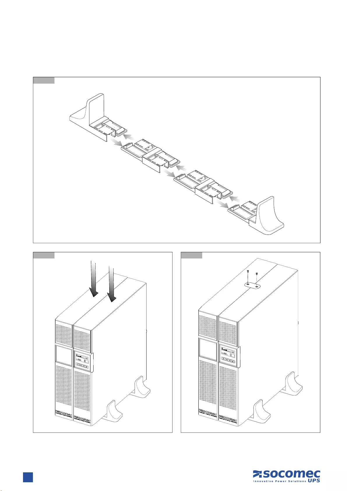
2. INSTALLATION
2.2.2 UPS Installation with multiple battery extensions
2.2.2-1
2.2.2-3
2.2.2-2
9
ENGLISH
NETYS PR RT — Ref.: IOMNETPRXX03-GB 02
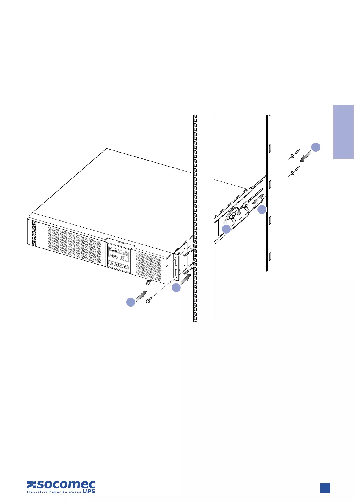
2. INSTALLATION
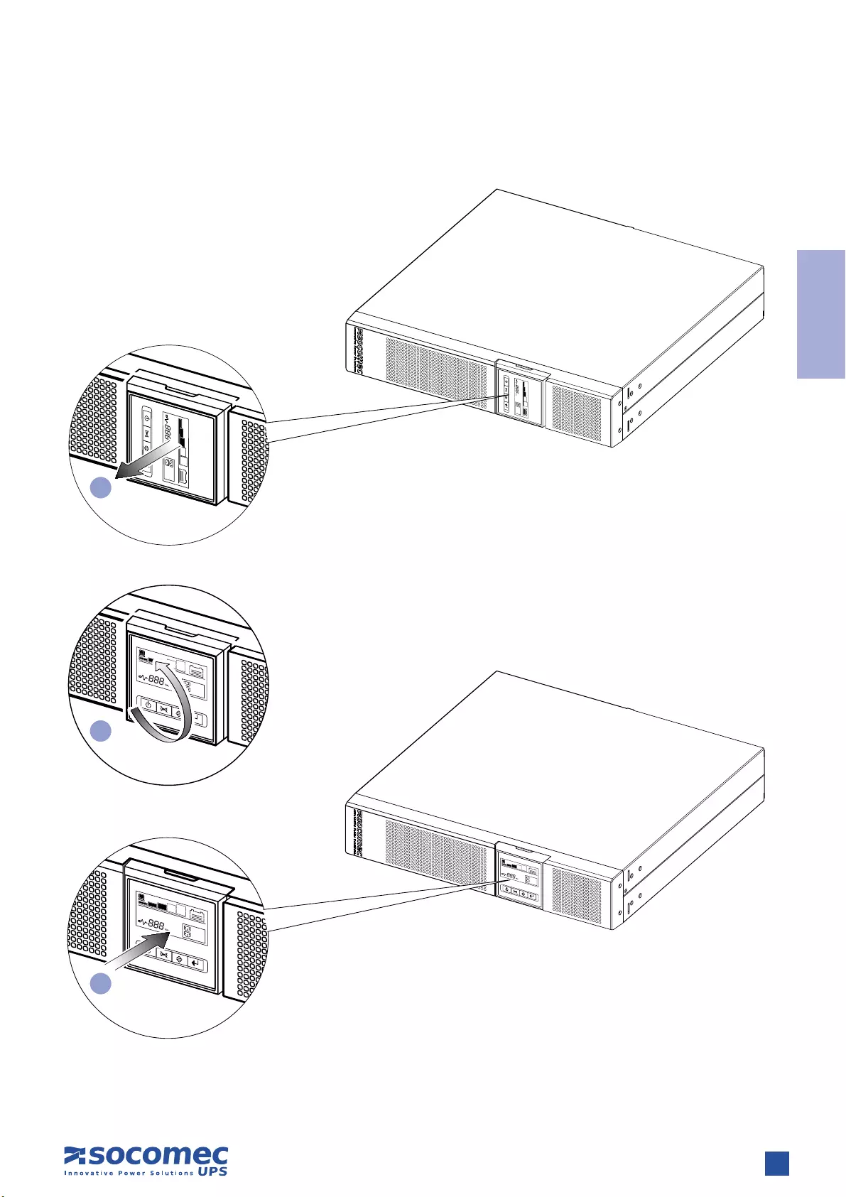
2.3 HORIZONTAL INSTALLATION ON RACK
2.3.1 Rotation of mimic pannel
1
2
3
10 NETYS PR RT — Ref.: IOMNETPRXX03-GB 02
2.3.2 Fitting rack brackets
2. INSTALLATION
11
ENGLISH
NETYS PR RT — Ref.: IOMNETPRXX03-GB 02
2.3.3 Fixing to rack
1. Adapt the length of the tracks to fit the rack.
2. Secure the wing nuts.
3. Fix the track to the rack.
4. Slot in the UPS and tighten the screws.
2. INSTALLATION
3
3
1
2
4
12 NETYS PR RT — Ref.: IOMNETPRXX03-GB 02
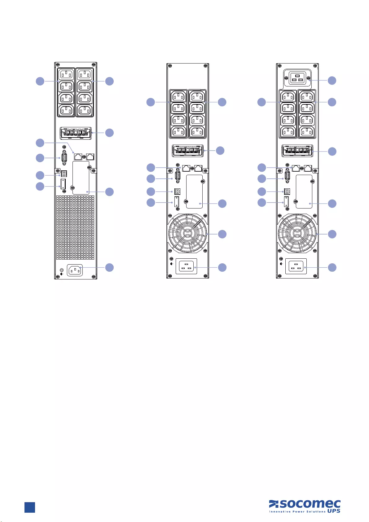
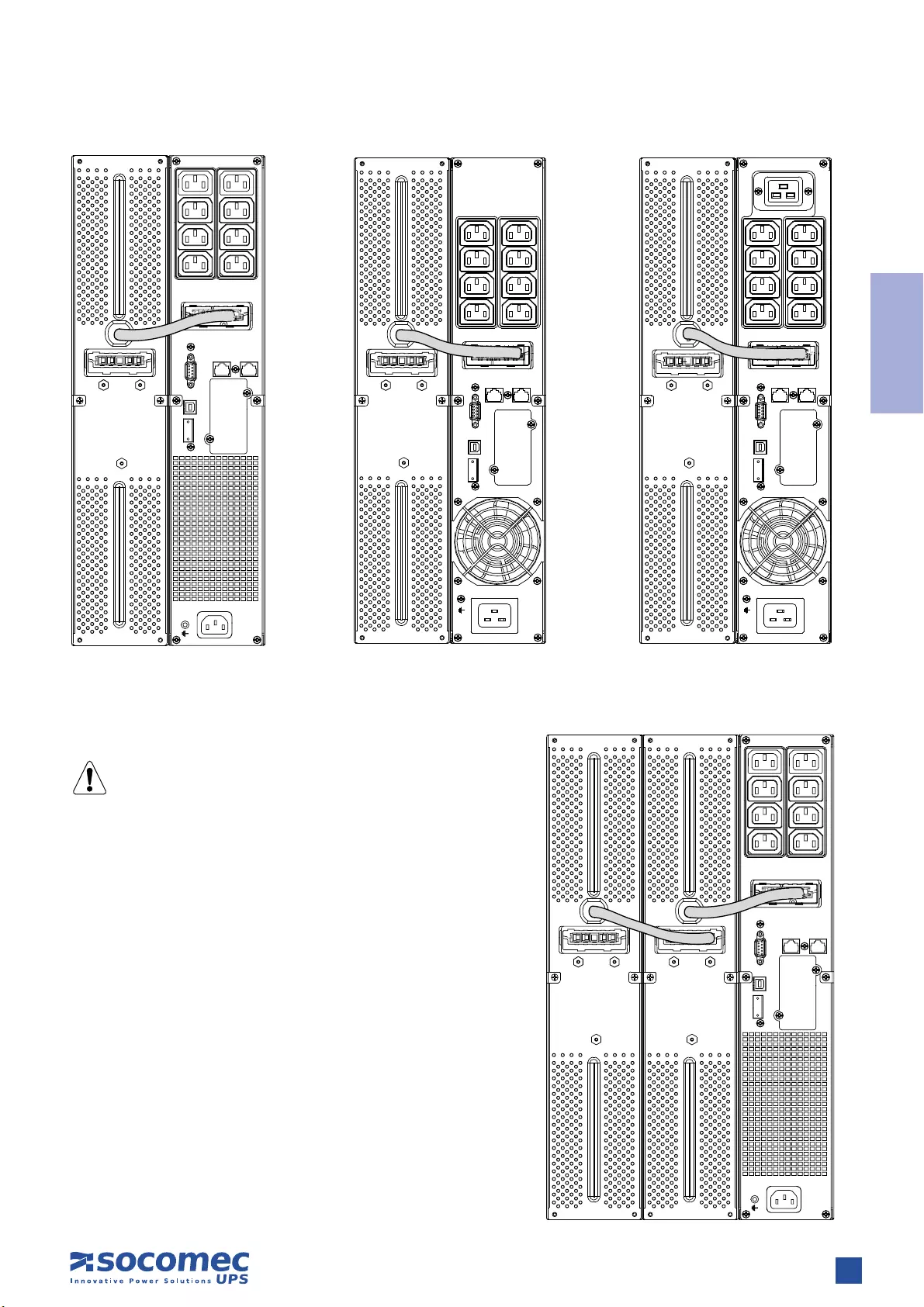
3. REAR VIEW
Key
A Mains input socket (IEC 320)
B Fan
C Output socket (full power)
D NTP protections (RJ45)
E Battery extension socket
F EPO (Emergency Power Off)
G RS232 serial connector (JBUS protocol)
H USB socket
I Power output sockets (IEC 320 — 10 A max)
L Slot for optional communication cards
LS1 OUT PUT
250 V~ 10A
LS2 OUT PUT
250 V~ 10A
IN OUT
NETW ORK /TEL EPHONE PROT ECTION
INTERFACE OPTION
EPO
USB
RS232
I NPU T 220- 240V~
EBM CONNECTOR
1700 VA 2200 VA 3300 VA
G
D
H
L
E
A
II
B
LS1 OUT PUT
250 V~ 10A
LS2 OUT PUT
250 V~ 10A
~
25KV 16A
IN OUT
NETW ORK /TEL EPHON E PROTECT ION
INTERFACE OPTION
EPO
USBRS232
I NPU T 220- 240V~
EBM CONNECTOR
G
D
H
L
E
A
II
C
B
FF
LS1 OUT PUT
250 V~ 10A
LS2 OUT PUT
250 V~ 10A
IN OUT
RS232 USB EPO
INTERFACE OPTION
INPUT 220-240V~
NETWORK PROTECTION
EBM CONNECTOR
G
D
H
L
E
A
II
F
13
ENGLISH
NETYS PR RT — Ref.: IOMNETPRXX03-GB 02
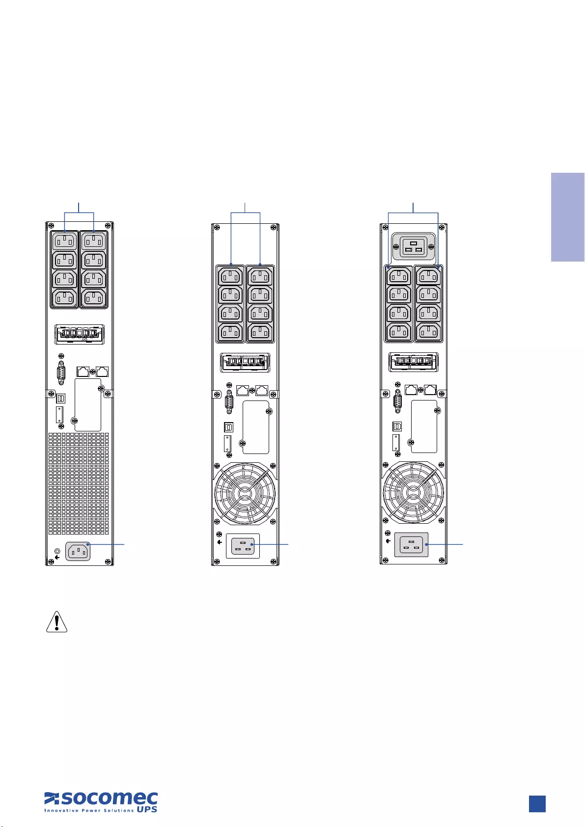
Connection to the mains power supply and load(s) must be made using cables of suitable cross section, in accordance with current
standards.
If not already provided, install a PDU panel allowing isolation of the mains supply upstream of the UPS. The panel must be equipped
with an automatic switch rated high enough to handle current draw on full load, and with a residual current device.
4. CONNECTIONS
The external contact MUST be dedicated and voltage-free, so as not to cause permanent damage to the UPS.
LS1 OUT PUT
250 V~ 10A
LS2 OUT PUT
250 V~ 10A
IN OUT
RS232 USB EPO
INTERFACE OPTION
INPUT 220-240V~
NETWORK PROTECTION
EBM CONNECTOR LS1 OUT PUT
250 V~ 10A
LS2 OUT PUT
250 V~ 10A
~
25KV 16A
IN OUT
NETW ORK /TEL EPHONE PROT ECTION
INTERFACE OPTION
EPO
USBRS232
I NPU T 220- 240V~
EBM CONNECTOR
LS1 OUT PUT
250 V~ 10A
LS2 OUT PUT
250 V~ 10A
IN OUT
NETW ORK /TEL EPHONE PROT ECTION
I N TE RF A CE OPTI ON
EPO
USB
RS232
I NPU T 220- 240V~
EBM CONNECTOR
OUT 230 V~
8 x IEC 320
OUT 230 V~
8 x IEC 320
OUT 230 V~
8 x IEC 320
IN 230 V~
Use the power
cable provided
IN 230 V~
Use the power
cable provided
IN 230 V~
Use the power
cable provided
1700 VA 2200 VA 3300 VA

14 NETYS PR RT — Ref.: IOMNETPRXX03-GB 02
5.1 SAFETY WARNINGS
• Before connecting the battery extension check it is fully compatible with the model of UPS in use.
• The use of battery extensions not supplied by the manufacturer is not recommended.
WARNING!
There is a risk of explosion if battery modules are replaced with others of an incorrect type.
• Depleted batteries are considered as toxic waste. When batteries need replaced disposal of used batteries using authorised waste
disposal companies. In accordance with local legislation, it is prohibited to dispose of batteries along with other industrial waste
or household refuse.
WARNING!
It is extremely dangerous to touch any part of the battery storage unit.
5.2 CONNECTION OF BATTERY EXTENSION
WARNING!
Before commencing any operations ensure that:
• the voltages of the UPS battery and battery extension are equal;
• the UPS has been shut down completely and all isolation switches are OFF;
• switches upstream of the UPS are OFF.
When connecting the UPS to the battery extension use the cable provided with the equipment only.
Any wiring error that results in the polarity of the battery being inverted could cause permanent damage to the
equipment.
5. CONNECTION OF BATTERY EXTENSION
15
ENGLISH
NETYS PR RT — Ref.: IOMNETPRXX03-GB 02
5. CONNECTION OF BATTERY EXTENSION
LS1 OUT PUT
250 V~ 10A
LS2 OUT PUT
250 V~ 10A
IN OUT
RS232 USB EPO
INTERFACE OPTION
INPUT 220-240V~
NETWORK PROTECTION
EBM CONNECTOR LS1 OUT PUT
250 V~ 10A
LS2 OUT PUT
250 V~ 10A
IN OUT
NETW ORK /TEL EPHON E PROTECT ION
INTERFACE OPTION
EPO
USB
RS232
IN PUT 220-240V~
EBM CONNECTOR
LS1 OUT PUT
250 V~ 10A
LS2 OUT PUT
250 V~ 10A
~
25KV 16A
IN OUT
NETW ORK /TEL EPHONE PROT ECTION
INTERFACE OPTION
EPO
USBRS232
IN PUT 220-240V~
EBM CONNECTOR
1700 VA 2200 VA 3300 VA
Connection of multiple batteries
WARNING!
A maximum of 2 EBMs can be used with NETYS PR
LS1 OUT PUT
250 V~ 10A
LS2 OUT PUT
250 V~ 10A
IN OUT
RS232 USB EPO
INTERFACE OPTION
INPUT 220-240V~
NETWORK PROTECTION
EBM CONNECTOR

16 NETYS PR RT — Ref.: IOMNETPRXX03-GB 02
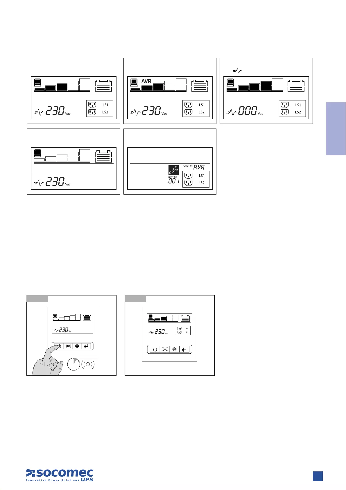
The mimic panel on the front of the UPS provides all essential information on the operating status of the appliance.
6. MIMIC PANEL
There is
Load
Automatic Voltage
Regulation is active
Load Level
(5 step) Battery status
Overload
General
Alarm
Battery
bad/fault
Input main
present
Input
Value
Setting
details
Programmable
outlets Two
segment
ON/OFF
UPS Test /
Alarm Silence
Enter
Select
17
ENGLISH
NETYS PR RT — Ref.: IOMNETPRXX03-GB 02
7.1 BATTERY RECHARGING
Connect the UPS to the mains voltage for approximately 8 hours to recharge the internal batteries.
The UPS can be used even with the batteries not fully charged, though if a power cut occurs backup duration will be shorter.
7. OPERATING MODES
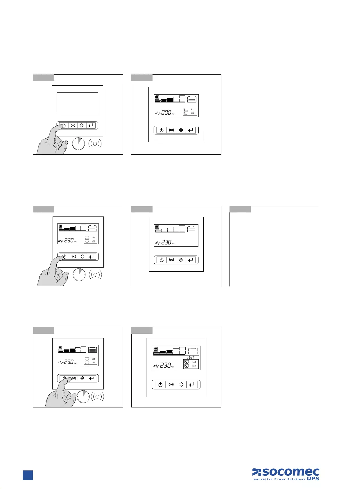
6 sec
7.2.1-1 7.2.1-2 Normal mode
7.2 SWITCHING THE NETYS PR ON AND OFF
7.2.1 Switching on with mains present
Power up all loads, one at a time.
Normal mode
Standby mode
Avr mode
Confi g mode
Battery mode
Icon will fl ash every second
18 NETYS PR RT — Ref.: IOMNETPRXX03-GB 02
10 sec
7.2.3 Switching off with mains present
7.2.4 Battery test
7. OPERATING MODES
• UPS is off but battery remains on
charge
• Shut down all loads, one at a time.
• Switch off mains power to shut
down completely.
7.2.3-1
7.2.4-1
7.2.3-2 Normal mode
7.2.4-2
7.2.3-3
6 sec
10 sec
7.2.2-1 7.2.2-2 Normal mode
7.2.2 Switching on with no mains power
Power up all loads, one at a time.
19
ENGLISH
NETYS PR RT — Ref.: IOMNETPRXX03-GB 02
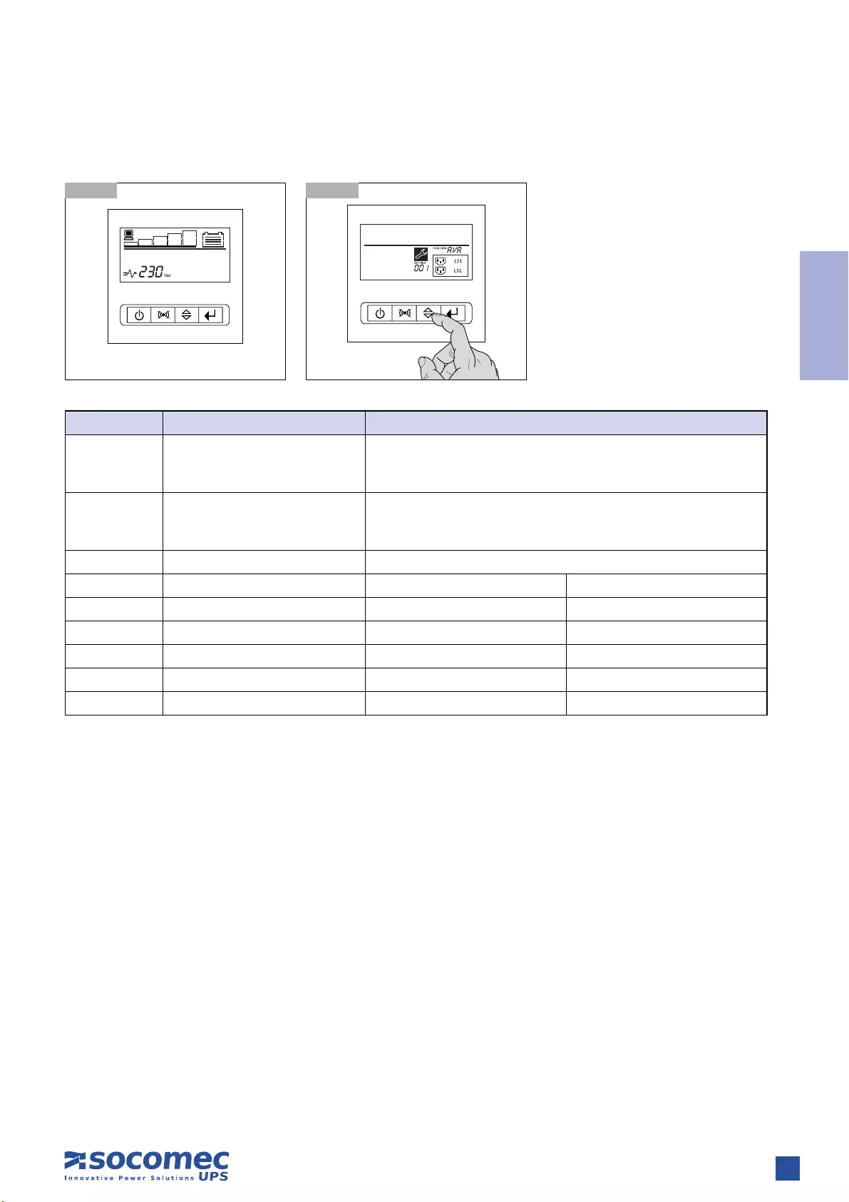
7.3-1 Standby mode 7.3-2
7. OPERATING MODES
7.3 SETTING MENU
Function Description Settings
OPV Output voltage mode select [220]= 220 V
[230]= 230 V
[240]= 240 V
AVR Input type select [001]= Normal range mode 1
[002]= Wide range mode 2
[003]= Generator mode from 3
EBM External battery module 0~2 is the number of external battery module
TEST Auto self-test [000]=Disable [001]=Enable
AR Automatic restart [000]=Disable [001]=Enable
GF Green function 4[000]=Disable [001]=Enable
BZ Buzzer control [000]=Disable [001]=Enable
LS1 Load segment 1 [000]=Turn off [001]=Turn on
LS2 Load segment 2 [000]=Turn off [001]=Turn on
1. (± 20% input voltage)
2. (-30 and +20% input voltage) @ 85% of nominal load
3. (40 Hz to 70 Hz input frequency)
4. Green Function is that when an insignificant amount of load is detected, the UPS will shut down output automatically on battery mode.
20 NETYS PR RT — Ref.: IOMNETPRXX03-GB 02
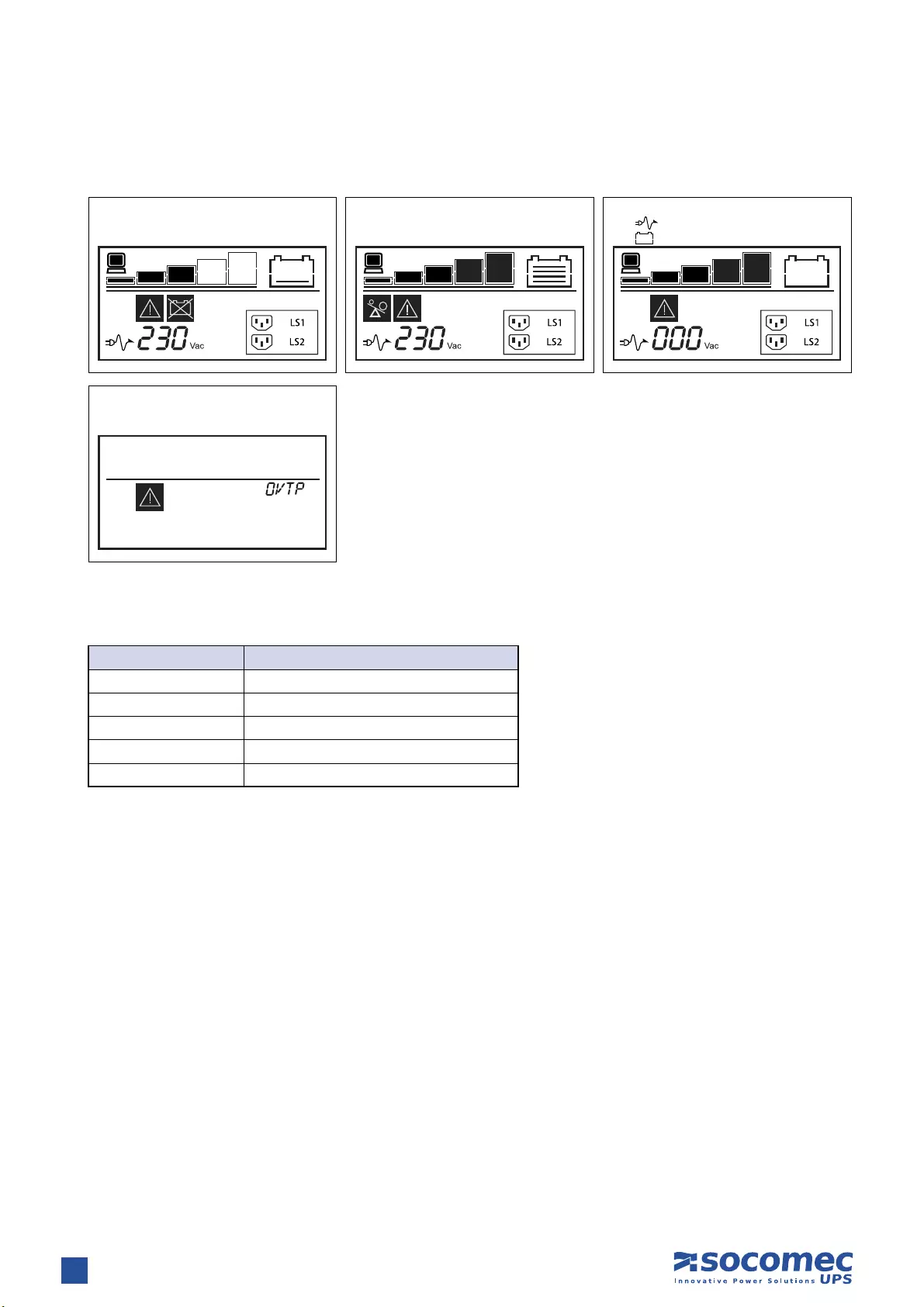
8. VISUAL AND AUDIBLE WARNING SIGNALS
8.1 ALARM INDICATION
The following table shows the description of the LCD display string:
Battery replace or
battery disconnect
Fault mode (over temperature)
Overload alarm Low battery mode
Icon will fl ash every second
Icon will fl ash every second
LCD Display String Description
OPVH The output is too high
OPVL The output is too low
OPST Output short
OVTP Internal temperature is too high
FNLK Fan is locked

21
ENGLISH
NETYS PR RT — Ref.: IOMNETPRXX03-GB 02
Communication software and accessories are available for monitoring status,for the purpose of optimising normal operation and
ensuring that shutdown at the end of backup time is managed correctly. Applications allow recording of all power outages and any
depletion of battery power so as to enable the activation of an automatic procedure for closing programs in an ordered sequence
and shutting down the system.
NETYS PR no-break systems are equipped with RS232 and USB serial communication interfaces, and slots for Web/SNMP cards.
Visit www.socomec.com and click on DOWNLOAD then SOFTWARE to find the communication software suitable for your require-
ments. See the CD provided.
9.2 USB INTERFACE
The UPS can communicate with the server directly by way of the USB interface using HID protocol, if available on the computer
operating system, without the need to install any additional software. Once connected UPS recognition occurs in the same way as for
any other peripheral, and the operating parameters can be managed with the OS service menu. Use the connecting cable provided.
9.3 RS232 INTERFACE (J-BUS/MODBUS)
This interface is required to run Local View ideal UPS monitoring and shutdown point-to-point solution for Windows®, Linux® and
Mac OS X® operating systems.
9.4 WEB/SNMP CARD (OPTION)
With this card installed, the UPS can be connected directly to a LAN (RJ45 ethernet) and controlled remotely from a WEB browser
using TCP/IP protocol. Reference should be made to the relevant literature for a full description of functionality.
9. COMMUNICATION
22 NETYS PR RT — Ref.: IOMNETPRXX03-GB 02
10. MAINTENANCE
WARNING!
The UPS generates HAZARDOUS INTERNAL VOLTAGES. All maintenance operations should be carried out by
AUTHORISED SERVICE ENGINEERS ONLY.
• The unit will operate to its maximum capability if kept powered round the clock (24/7); this ensures that the batteries will always
be properly charged.
• If the appliance is not to be used for any length of time wait until the batteries are fully charged (connection to mains power supply
for 8 hours continuous) before shutting the UPS down.
• Recharge the batteries for a duration of 24 hours at least every 4 weeks when the unit is not in use.
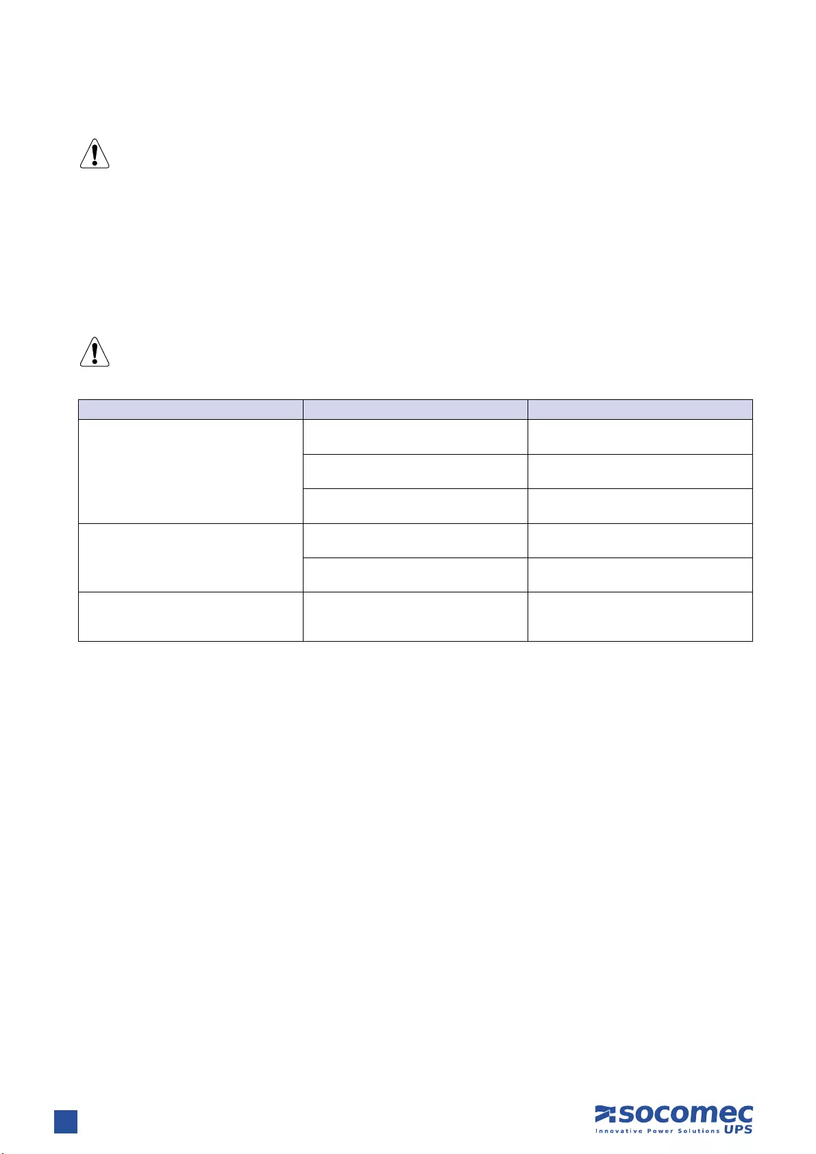
10.1 MINOR TROUBLESHOOTING
WARNING!
If problems persist or recur frequently after following the procedures indicated in this section contact the
SOCOMEC UPS After Sales Service, providing a full description of the problem.
Problem Possible cause Solution
The UPS works in battery mode even if
mains power is available
Poor connection to the input mains Check the connection of the cable to the
UPS and to the mains outlet
The mains voltage is out of range No solution because mode of operation
is correct
Input protection triggered (blown fuse or
automatic switch)
Replace the input fuse with another of the
same type or reset the automatic switch
Back-up time shorter than expected
Batteries not fully charged Leave the batteries to charge for 8 hours
consecutively
Batteries not working properly Have the batteries replaced by
authorised personnel
The UPS stalls/goes into overload alarm Overload on the load line
Check that the load applied is not
greater than the maximum permitted or
reduce the load power requirement

23
ENGLISH
NETYS PR RT — Ref.: IOMNETPRXX03-GB 02
11. TECHNICAL SPECIFICATIONS
1. back-up time at 75 % of the nominal power
Models
Power 1700 VA 2200 VA 3300 VA
Power 1350 W 1800 W 2700 W
Electrical specifications — Input
Voltage 161 V ±4% (selecting wide mode) — 276 V ±4% (230 Vnom)
Frequency 50/60 Hz with automatic selection
Mains connection IEC 320-C14 (10 A) IEC 320-C20 (16 A) IEC 320-C20 (16 A)
Electrical specifications — Output
Voltage (in Normal Mode with AVR)
The AVR increases (boost 1) the output voltage by 14%
when the input voltage drops below 90% of the nominal value.
The AVR decreases (bucks) the output voltage by 12%
when the input voltage rises above 106% of the nominal value.
Voltage (in Battery Mode) 230 V ±5%
Frequency (in Battery Mode) 50/60 Hz ±0,1 Hz
Wave form Pure Sine Wave
Transfer time 2÷6 ms (typical),
Normal Mode protections Overload (110% for 3 minutes)
Battery Mode protections Overload (110% for 30 seconds); shortcircuit protected
Load connection socket IEC 320 8 (10 A) 8 (10 A) 8 (10 A) + 1 (16 A)
Battery
Typical back-up time16 min 8 min 6 min
Battery recharge 4 hours 80% Cn (after full discharge).
Under permanent charge even when the UPS is off (mains present).
Reporting and Communication
Communication interface RS232 — USB RS232 — USB RS232 — USB
Ethernet adapter Net Vision (TCP/IP & SNMP) optional card
Local communication software UPS Management software
Local and remote communication
software
Local View ideal UPS monitoring and shutdown point-to-point solution for Windows®,
Linux® and Mac OS X® operating systems
Data line protection NTP data line suppressor: RJ45 10 Base T
Environment
Noise level (normal mode) < 50 dBA (at 1 metre) < 50 dBA (at 1 metre) < 55 dBA (at 1 metre)
Temperature 0÷40 °C (15÷25 °C for optimum battery life)
Reference standards EN 62040-1 (safety), EN 62040-2 (EMC)
Mechanical characteristics
Dimensions (W x D x H) 2U 440 x 436 x 87 mm 440 x 608 x 87 mm 440 x 608 x 87 mm
Net weight 18 kg 28.2 kg 31.5 kg


VALID FOR FRANCE VALID FOR ITALY
ISO 9001
FM 28237
ISO14001
EMS 553476
www.socomec.com
YOUR DISTRIBUTOR
To help protect the environment, this document has been printed on PEFC paper (Programme for the Endorsement of Forest Certification)
Non contractual document. © 2012, Socomec SA. All rights reserved.
HEAD OFFICE
SOCOMEC GROUP
S.A. SOCOMEC capital 11 149 200 € — R.C.S. Strasbourg B 548 500 149
B.P. 60010 — 1, rue de Westhouse — F-67235 Benfeld Cedex
SOCOMEC UPS Strasbourg
11, route de Strasbourg — B.P. 10050 — F-67235 Huttenheim Cedex- FRANCE
Tel. +33 (0)3 88 57 45 45 — Fax +33 (0)3 88 74 07 90
admin.ups.fr@socomec.com
SOCOMEC UPS Isola Vicentina
Via Sila, 1/3 — I — 36033 Isola Vicentina (VI) — ITALY
Tel. +39 0444 598611 — Fax +39 0444 598622
hr.ups.it@socomec.com
SALES, MARKETING AND SERVICE MANAGEMENT
SOCOMEC UPS Paris
95, rue Pierre Grange
F-94132 Fontenay-sous-Bois Cedex — FRANCE
Tel. +33 (0)1 45 14 63 90 — Fax +33 (0)1 48 77 31 12
dcm.ups.fr@socomec.com
Socomec UPS worldwide
IN WESTERN EUROPE
BELGIUM
Schaatsstraat, 30 rue du Patinage
B — 1190 Bruxelles
Tel. +32 (0)2 340 02 34
info.ups.be@socomec.com
FRANCE
95, rue Pierre Grange
F — 94132 Fontenay-sous-Bois Cedex
Tel. +33 (0)1 45 14 63 90
dcm.ups.fr@socomec.com
GERMANY
Heppenheimer Straße 57
D — 68309 Mannheim
Tel. +49 (0) 621 71 68 40
info.ups.de@socomec.com
ITALY
Via Leone Tolstoi, 73 — Zivido
20098 San Giuliano Milanese (MI)
Tel. +39 02 98 242 942
info.ups.it@socomec.com
PORTUGAL
Núcleo Empresarial de Mafra II
Av. Dr. Francisco Sá Carneiro, Fracção N
2640-486 Mafra
Tel. +351 261 812 599
info.ups.pt@socomec.com
SPAIN
C/Nord, 22 Pol. Ind. Buvisa
E — 08329 Teià (Barcelona)
Tel. +34 935 407 575
info.ups.sib@socomec.com
THE NETHERLANDS
Duwboot 13
NL — 3991 CD Houten
Tel. +31 (0)30 760 0911
info.ups.nl@socomec.com
UNITED KINGDOM
Units 7A-9A Lakeside Business Park
Broadway Lane — South Cerney
Cirencester — GL7 5XL
Tel. +44 (0)1285 863300
info.ups.uk@socomec.com
OTHER COUNTRIES
Tel. +34 935 407 575
info.ups.europe@socomec.com
IN EASTERN EUROPE,
MIDDLE EAST, AFRICA
UNITED ARAB EMIRATES
LIU-E17 DAFZA
371355 Dubai airport free zone
Dubai (United Arab Emirates)
Tel.: +971 (0) 4 29 98 441
info.ups.ae@socomec.com
POLAND
ul. Mickiewicza 63
01-625 Warszawa
Tel. +48 22 825 73 60
info.ups.pl@socomec.com
ROMANIA
Heliade Intre Vii Street no.8, 2 District
023383 Bucharest
Tel. +40 21 319 36 88 ( 89, 81, 82)
info.ups.ro@socomec.com
RUSSIA
4th Street 8 Marta, 6A, 405
125167 — Moscow
Tel. +7 495 775 19 85
info.ups.ru@socomec.com
SLOVENIA
Savlje 89
SI — 1000 Ljubljana
Tel. +386 1 5807 860
info.ups.si@socomec.com
TURKEY
Masuklar Yokusu No:57/2
34357 Besiktas
Istanbul
Tel. +90 212 2580810
info.ups.tr@socomec.com
OTHER COUNTRIES
Tel. +39 0444 598 611
info.ups.emea@socomec.com
IN ASIA PACIFIC
AUSTRALIA
Unit 3, 2 Eden Park Drive (Rydecorp)
Macquarie Park NSW 2113
Tel. +61 2 9325 3900
info.ups.au@socomec.com
CHINA
Universal Business Park
B33, Floor 3, 10 Jiuxianqiao Lu,
Chaoyang, Beijing 100016 P.R., China
Tel. +86 10 59756108
info.ups.cn@socomec.com
INDIA
B1, IInd Floor, Thiru-Vi-Ka-Industrial Estate
Guindy
Chennai – 600 032
Tel. +91 44 3921 5400
info.ups.in@socomec.com
MALAYSIA
31 Jalan SS 25/41- Mayang Industrial Park
47301 Petaling Jaya.- Selangor, Malaysia
Tel. +603 7804 1153
info.ups.my@socomec.com
SINGAPORE
31 Ubi Road 1 #01-00 (Lobby B)
Aztech Building
Singapore 408694
Tel. +65 6506 7600
info.ups.sg@socomec.com
THAILAND
No.9 Soi Vibhavadirangsit 42
Vibhavadirangsit Rd, Ladyao
Chatujak Bangkok 10900
Tel. +66 2 941-1644-7
info.ups.th@socomec.com
VIETNAM
539/23 Luy Ban Bich St.,
Phu Thanh Ward, Tan Phu Dist
Ho Chi Minh City
Tel. +84-839734.990
info.ups.vn@socomec.com
ASIA PACIFIC HEAD OFFICE
Tel. +65 6507 9770
info.ups.apac@socomec.com
IN AMERICA
LATIN AMERICAN COUNTRIES
Tel. +34 935 407 575
info.ups.sib@socomec.com
*IOMNETPRXX03-GB 02*
IOMNETPRXX03-GB 02 09.2012
FAQ: Types of Manuals and Their Contents
socomec Netys RT Manuals come in various types, each serving a specific purpose to help users effectively operate and maintain their devices. Here are the common types of socomec Netys RT User Guides and the information they typically include:
- User Manuals: Provide comprehensive instructions on how to use the device, including setup, features, and operation. They often include troubleshooting tips, safety information, and maintenance guidelines.
- Service Instructions: Designed for technicians and repair professionals, these manuals offer detailed information on diagnosing and repairing issues with the device. They include schematics, parts lists, and step-by-step repair procedures.
- Installation Guides: Focus on the installation process of the device, providing detailed instructions and diagrams for proper setup. They are essential for ensuring the device is installed correctly and safely.
- Maintenance Manuals: Provide guidance on routine maintenance tasks to keep the device in optimal condition. They cover cleaning procedures, part replacements, and regular servicing tips.
- Quick Start Guides: Offer a concise overview of the essential steps needed to get the device up and running quickly. They are ideal for users who need immediate assistance with basic setup and operation.
Each type of socomec Netys RT instruction is designed to address specific needs, ensuring users have the necessary information to use, maintain, and repair their devices effectively.
Related Instructions for socomec Netys RT:
3
DIRIS Q800
Quick start PDF User Guide (@8BLNR7), socomec DIRIS Q800 Analytical Instruments (20.01.2025)
2
1109
189
4
DIRIS Digiware C Series
Operation & user’s manual socomec DIRIS Digiware C Series User Guide (Operation & user’s manual), @V4V6L2
56
989
179
5
ISOM AS425
Manual Guide: socomec ISOM AS425 (N99Z6V, Upd.10th Dec 2024)
8
244
57
7
Green Power 2.0 10
52
910
228
Battery Charger Devices by Other Brands:
|
BC BATTERY CONTROLLER BC K900 EDGE Manual BC BATTERY CONTROLLER BC K900 EDGE User Manual (Manual ), @634Q6F BC BATTERY CONTROLLER K900 EDGE 6V / 12V / 12V CAN-BUS 16 Mar 2025 | 2 |
|
|
Brunton Hydrogen Reactor Manual Brunton Hydrogen Reactor Manual (Manual ), @CD8F69 USING THE REACTOR TO CHARGE OR POWER YOUR 13 Jan 2025 | 1 |
|
|
Ryobi P111 Operator’s Manual Guide: Ryobi P111 (6PE4QP, Upd.30th Apr 2025) SAVE THIS MANUAL FOR FUTURE REFERENCE 30 Apr 2025 | 20 |
|
|
Webasto Stand for Webasto charging station Installation Instructions Manual Stand for Webasto charging station (Battery Charger ePDF User Guide, #RO9DN3) Stand for Webasto charging station 13 Nov 2024 | 27 |
Categories:
Power Hammer
Battery Pack
Power Tool
Multimeter
Network Accessory
Computer Hardware
16
Catalogue 2013
Single-phase UPS
Simple to install
•
IEC input and output connections
(1100‑3000 VA) or terminal input and output
connections with built-in magnetothermal
input switch (5000-11000 VA).
•
Compact footprint for installation in rack
cabinets.
•
Attractive design.
Easy to use
•
No configuration necessary on first startup.
•
Wide range of communication protocols for
integration into LAN networks or Building
Management Systems (BMS).
•
Clear LED interface with buzzers that
immediately indicate the operating status
of the UPS, even for less specialist users
(1100-3000 VA).
•
LCD display with menu available in
6 languages (5000‑11000 VA).
Meets practical needs
•
Online double conversion technology with
sinusoidal waveform, completely filters out
all disturbances from / to the mains power
supply and ensures maximum protection of
the utility.
•
Modular battery extension (EBM) to meet
all back-up time requirements, even after
installation.
•
Possibility of 1+1 parallel redundant
configuration to maximise the availability of
critical utilities, even in the event of a module
breakdown (5000-11000 VA).
N T
Y
S RT
from 1100 to 11000 VA
complete solution for IT infrastructures
The solution for
>
Switching
>
Storage
>
Servers and networking
devices
>
VoIP communication systems
>
Structured cabling systems
>
Control systems
>
Video surveillance systems
Technology
>
VFI “online double conversion”
GAMME 110 A
Advantages
Certifications
new
From 5 to 11 kVA

005 DRWNETRT-XX
5-7-9-11 kVA
Installation and operating manual
GB

2
5-11 kVA — Ref.: IOMNETRTXX01-GB 00
This SOCOMEC UPS appliance is guaranteed against possible defects of manufacture and materials, for a period of 12 months from
the date of purchase (local warranty conditions are applicable in addition to the general conditions). The present warranty certificate
should NOT be mailed, but kept by the customer together with the proof of purchase document, for use in the event of a claim being
made for repairs or replacement under warranty.
The warranty period runs from the date on which the new product was purchased by the end user at the showroom of an official
resaler (the reference data is that indicated on the proof-of-purchase document).
The warranty is offered on carry-in terms: components and labour for repairs supplied free of charge, and in the case of a replace—
ment, the product to be returned to SOCOMEC UPS or to authorized service centres, at the customer’s own risk and expense.
To claim service under warranty, the user must abide by the following rules:
• The product is to be returned only in the original packing. Any damage occurring in transit to a product not in its original packing
will not be covered by the warranty;
• The product must be accompanied by proof of purchase: a document (delivery note, invoice, counter receipt) indicating the date
of the purchase, which must also indicate the essential identification data for the product (model, serial numer). The sender must
also attach the acceptance number issued to authorize the return of the product, together with a detailed description of the defect
encountered. If any of these elements is missing, the warranty will be invalidated. The authorization number is issued by service
centres over the telephone, after being informed of the malfunction in respect of which a claim is submitted;
• Should it be impossible to furnish proof of purchase, the serial number and date of manufacture will be used to calculate the
probable expiry date of the warranty; this could result in a reduction of the original warranty period.
The warranty on the product does not cover damage occasioned by thoughtlessness (improper use: wrong input power, explosions,
excessive humidity, temperature, poor ventilation, etc.), tampering or any unauthorized repair work.
During the warranty period, SOCOMEC UPS remains at liberty to decide whether the product should be repaired, or whether to
replace defective parts with new parts, or with used parts that are equivalent to new parts in terms of functionality and perfor—
mance.
In the case of batteries, warranty is valid only if the battery has been recharged periodically in accordance with the manufacturer’s
directions. Accordingly, it is advisable to check, following purchase, that the date of the next recharge indicated on the packing
has not expired.
Optionals.
A 12-month carry-in warranty is offered on optionals.
Software products.
Software products are guaranteed for 90 days. The software is guaranteed to work substantially as indicated in the manual accom—
panying the product. Hardware media or accessories (e.g. diskettes, cables, etc.) used with appliances are guaranteed free of
material or manufacturing defects under normal conditions of use for a period of 12 months from the date of purchase.
On no account will SOCOMEC UPS ackowledge liability for damages (including loss of income, interruption of business activity, loss
of information or other economic losses, of whatever magnitude) deriving from the use of the product.
The present conditions are regulated by the laws of Italy. Disputes shall be submitted to the jurisdiction of the Vicenza Law
Courts.
WARRANTY CERTIFICATE AND CONDITIONS
SOCOMEC UPS retains the full and exclusive ownership rights over this document. Only a personal right to utilize the document for
the application indicated by SOCOMEC UPS is granted to the recipient of such document. All reproduction, modification, dissemi—
nation of this document whether in part or whole and by any manner are expressly prohibited except upon Socomec’s express
prior written consent.
This document is not a specification. SOCOMEC UPS reserves the right to make any changes to data without prior notice.

3
5-11 kVA — Ref.: IOMNETRTXX01-GB 00
TABLE OF CONTENTS
ENGLISH
1. SAFETY STANDARDS. . . . . . . . . . . . . . . . . . . . . . . . . . . . . . . . . . . . . . . . . . . . . . . . . . . . . . 4
1.1 Important . . . . . . . . . . . . . . . . . . . . . . . . . . . . . . . . . . . . . . . . . . . . . . . . . . . . . . . 4
1.2 Description of the symbols used on the labels applied to the unit . . . . . . . . . . . . . 5
2. INSTALLATION . . . . . . . . . . . . . . . . . . . . . . . . . . . . . . . . . . . . . . . . . . . . . . . . . . . . . . . . . . . 6
2.1 Environmental requirements for installation . . . . . . . . . . . . . . . . . . . . . . . . . . . . . . 6
2.2 Electrical requirements . . . . . . . . . . . . . . . . . . . . . . . . . . . . . . . . . . . . . . . . . . . . . 6
2.3 Vertical installation . . . . . . . . . . . . . . . . . . . . . . . . . . . . . . . . . . . . . . . . . . . . . . . . . 7
2.4 Horizontal installation on rack . . . . . . . . . . . . . . . . . . . . . . . . . . . . . . . . . . . . . . . . 9
3. REAR VIEW . . . . . . . . . . . . . . . . . . . . . . . . . . . . . . . . . . . . . . . . . . . . . . . . . . . . . . . . . . . . . 13
4. CONNECTIONS . . . . . . . . . . . . . . . . . . . . . . . . . . . . . . . . . . . . . . . . . . . . . . . . . . . . . . . . . 14
4.1 Connection terminal strips . . . . . . . . . . . . . . . . . . . . . . . . . . . . . . . . . . . . . . . . . 14
4.2 Connection of UPS . . . . . . . . . . . . . . . . . . . . . . . . . . . . . . . . . . . . . . . . . . . . . . . 15
5. CONNECTION OF BATTERY EXTENSION . . . . . . . . . . . . . . . . . . . . . . . . . . . . . . . . . . . . . 16
5.1 Safety warnings . . . . . . . . . . . . . . . . . . . . . . . . . . . . . . . . . . . . . . . . . . . . . . . . . 16
5.2 Connection of battery extension . . . . . . . . . . . . . . . . . . . . . . . . . . . . . . . . . . . . . 16
6. CONNECTION OF BY-PASS AND SINGLE UPS . . . . . . . . . . . . . . . . . . . . . . . . . . . . . . . . 18
6.1 Installation of BY-PASS and single UPS . . . . . . . . . . . . . . . . . . . . . . . . . . . . . . . 18
6.2 Connection of BY-PASS to single UPS . . . . . . . . . . . . . . . . . . . . . . . . . . . . . . . . 19
7. CONNECTION OF BY-PASS AND UPS IN PARALLEL . . . . . . . . . . . . . . . . . . . . . . . . . . . 23
7.1 Vertical installation of BY-PASS and UPS in parallel . . . . . . . . . . . . . . . . . . . . . . 23
7.2 Rack installation of BY-PASS and UPS in parallel . . . . . . . . . . . . . . . . . . . . . . . . 24
7.3 Connection of BY-PASS and UPS in parallel . . . . . . . . . . . . . . . . . . . . . . . . . . . . 25
7.4 Connection of BY-PASS to UPS in parallel . . . . . . . . . . . . . . . . . . . . . . . . . . . . . 27
8. MIMIC PANEL . . . . . . . . . . . . . . . . . . . . . . . . . . . . . . . . . . . . . . . . . . . . . . . . . . . . . . . . . . . 28
9. OPERATING MODES . . . . . . . . . . . . . . . . . . . . . . . . . . . . . . . . . . . . . . . . . . . . . . . . . . . . . 29
9.1 Basic settings . . . . . . . . . . . . . . . . . . . . . . . . . . . . . . . . . . . . . . . . . . . . . . . . . . . 29
9.2 Operation in BY-PASS mode for maintenance purposes — single UPS . . . . . . . . 30
9.3 Operation in BY-PASS mode — UPS in parallel for maintenance purposes . . . . . 32
10. COMMUNICATION . . . . . . . . . . . . . . . . . . . . . . . . . . . . . . . . . . . . . . . . . . . . . . . . . . . . . . 33
10.1 Communication solutions . . . . . . . . . . . . . . . . . . . . . . . . . . . . . . . . . . . . . . . . . 33
10.2 RS232 interface . . . . . . . . . . . . . . . . . . . . . . . . . . . . . . . . . . . . . . . . . . . . . . . . 33
10.3 Integrated WEB/SNMP card . . . . . . . . . . . . . . . . . . . . . . . . . . . . . . . . . . . . . . . 33
10.4 Use of warning relay interface . . . . . . . . . . . . . . . . . . . . . . . . . . . . . . . . . . . . . . 33
11. MAINTENANCE . . . . . . . . . . . . . . . . . . . . . . . . . . . . . . . . . . . . . . . . . . . . . . . . . . . . . . . . . 36
11.1 Minor troubleshooting . . . . . . . . . . . . . . . . . . . . . . . . . . . . . . . . . . . . . . . . . . . . 36
12. TECHNICAL SPECIFICATIONS . . . . . . . . . . . . . . . . . . . . . . . . . . . . . . . . . . . . . . . . . . . . 37

4
5-11 kVA — Ref.: IOMNETRTXX01-GB 00
1. SAFETY STANDARDS
1.1 Important
This manual should be kept carefully in a safe place near the UPS, so that it can be consulted by the operator at any time for any
information that may be needed regarding correct use of the unit. Read the manual carefully before connecting the unit to the a.c.
mains supply and to the downstream appliances. Before the UPS NETYS RT is put into commission, the user must be perfectly
familiar with its operation, with the position of all the controls and with the technical and functional characteristics of the unit, so as
to ensure there will be no risk to any persons or to the appliance itself.
• The electrical installation must be entrusted EXCLUSIVELY to a skilled engineer, following the instructions provided
exactly.
• Before being started up, the unit must be equipotentially bonded, in accordance with current safety regulations. The earth
wire of the UPS must then be connected to an efficient earth system.
• If the earth connection is not made, the appliances connected to the UPS will not be equipotentially bonded. In this situation,
the manufacturer declines all liability for any damage or accidents that could derive from failure to observe the requirements.
• Should a power outage occur (UPS in stand-alone mode), do not disconnect the power cord from the mains, as this will
break the earth connection to bonded appliances.
• All subsequent maintenance operations must be entrusted only to authorized service engineers. The UPS generates high
internal voltages that could be hazardous for a maintenance operative not in possession of the appropriate skills and training for
this type of work.
• If a hazard situation should arise at any moment when the UPS is in use, isolate the unit from the power supply (by operating
a switch at the upstream PDU if possible) and switch the appliance off completely by running the shutdown procedure.
• The UPS houses a source of electrical energy, namely its batteries. The output of the UPS may be under power even
when the appliance is not connected to the a.c. mains supply.
• Never force, break or attempt to open the batteries. These batteries are sealed, maintenance-free components contai—
ning substances that are harmful to health and a source of environmental pollution. If liquid can be seen leaking from the
battery, or a white powdery residue is noticeable, do not switch the UPS on.
• Avoid exposing the UPS to contact with water or any liquids generally. Do not allow foreign objects to come into contact
with the materials.
• If the appliance is to be scrapped, it must be entrusted exclusively to a specialist waste disposal company. These companies
will split up and dispose of the various components in accordance with statutory regulations in the country of purchase.
• Use the UPS in accordance with the technical specifications indicated in this manual (chapter 11).
• Avoid connecting the output neutral to earth. The UPS does not alter the function of mains neutral in any way; if neutral needs to
be modifed downstream of the UPS, an isolation transformer must be used.
• To meet the operating requirements for the Emergency Switch Device (ESD), a specific RJ11 input with remote ESD/EPO function
is available.
• In the event that the equipment has no automatic backfeed protection contactor device, make certain that:
— the user/installer attaches warning labels to all mains isolating switches located remotely from the area where the UPS is sited, in
order to inform service personnel that the circuit is connected to a UPS.
— an external isolating device is installed, as indicated in figure 1-1.
• The product you have selected, given the specified conditions of use, capacity and performance limits, is designed exclusively for
commercial and industrial service. The use of the product in “critical applications” could require compliance with statutory regula—
tions and standards, or with specific local bylaws, or adaptation to SOCOMEC UPS recommendations. For this type of use, in any
event, it is advisable to contact SOCOMEC UPS beforehand for confirmation regarding the capacity of products to meet required
levels of safety, performance and reliability. The expression “critical applications” covers, in particular, life support systems, medical
applications, commercial transport, nuclear facilities or any other systems where failure of the product might on occasion cause
serious damage to persons or property.
WARNING!
This is a product for commercial and industrial application in the second environment – installation restrictions or
additional measures may be needed to prevent disturbances.

5
ENGLISH
5-11 kVA — Ref.: IOMNETRTXX01-GB 00
2. SAFETY
1.2 Description of the symbols used on the labels applied to the unit
All the precautions and the warnings on the labels and plates on the inside and outside of the equipment should be respected.
DANGER! HIGH VOLTAGE (BLACK/YELLOW)
GROUND TERMINAL
READ THE USER MANUAL BEFORE USING THE UNIT
085 DRWNETRT-XX
1-1
Legend.
B Contactor solenoid.
Q Mains input thermal-magnetic switch
T Two-pole contactor 90 A AC1; coil voltage: according to the Mains input.
UPS.
External power
distribution unit
ISOLATE THE UPS BEFORE WORKING ON THIS
CIRCUIT.

6
5-11 kVA — Ref.: IOMNETRTXX01-GB 00
2. INSTALLATION
2.1 Environmental requirements for installation
Consult the following check list when installing the UPS:
• NETYS RT units are designed for use in enclosed environments.
• Position the UPS on a flat and stable surface in a properly ventilated room, well away from heat sources and avoiding direct expo—
sure to sunlight.
• Ambient temperature should be maintained between 0 °C and 40 °C, and relative humidity below 90% (without condensation);
the optimum temperature in terms of maximizing battery life is 15-20 °C.
• Check that the UPS will not be installed in a dust-laden environment.
• Be certain that a clearance of at least 20 cm is left on all sides of the unit to ensure adequate ventilation and provide access to the
rear panel.
• Take care not to stand the UPS or any other heavy object on cables.
• Check that the operating voltage and frequency settings are correct for the mains power supply at the installation site. Details for
the UPS will be found on the data plate affixed to the rear panel.
• When making the RS232 serial connection, use only the cables and accessories supplied or specified by the manufacturer.
• When the UPS is first used, it is advisable to leave the battery on charge for a minimum of 8 hours.
PRECAUTIONS IN THE EVENT OF DAMAGE
DO NOT OVERTURN THE BATTERIES.
Packing materials that have been broken, punctured or torn in such a way as to reveal the contents must be kept
separate in a secure area, and inspected by skilled staff. Any packing considered unsuitable for shipment of the
contents must be set aside immediately and kept secure, and the sender or recipient contacted.
2.2 Electrical requirements
The installation and the system must comply with pertinent national statutory regulations.
The fixed power distribution unit must include protection and isolation for the utility supply and the back-up supply. In the event that
a residual current device is installed on the UPS input line (optional), this must be located upstream of the power distribution unit.
The following table indicates the sizing of input protection devices that will ensure correct installation.
WARNING!
Use type B four-pole selective (S) RCDs Any leakage currents at the loads will be added to that of the UPS, so that
current peaks can occur during transients (loss and restoration of mains supply), although these will be of very
short duration. Where loads generate high leakage current, make certain the rating of the RCD is suitably matched.
In any event, always conduct a preliminary test for current leakage to eart
Electrical requirements
UPS Thermal-magnetic switch
on input
Recommended selective
RCD on input
Minimum cable section
5 kVA 40 C 0,1 A type B 6 mm
2
7 kVA 40 C 0,1 A type B 8 mm
2
9 kVA 63 D 0,1 A type B 10 mm
2
11 kVA 63 D 0,1 A type B 10 mm
2

7
ENGLISH
5-11 kVA — Ref.: IOMNETRTXX01-GB 00
2. INSTALLATION
2.3 Vertical installation
2.3.1 UPS Installation
4
4
2
1
3
031 DRWNETRT-XX
115 DRWNETRT-XX
059 DRWNETRT-XX
102 DRWNETRT-XX
103 DRWNETRT-XX

8
5-11 kVA — Ref.: IOMNETRTXX01-GB 00
2.3.2 UPS installation with multiple battery
extensions
2. INSTALLATION
4
2
3
069 DRWNETRT-XX
033 DRWNETRT-XX
059 DRWNETRT-XX
068 DRWNETRT-XX
065 DRWNETRT-XX
1

9
ENGLISH
5-11 kVA — Ref.: IOMNETRTXX01-GB 00
2. INSTALLATION
2.4 Horizontal installation on rack
2.4.1 Rotation of mimic pannel
122 DRWNETRT-XX
121 DRWNETRT-XX
124 DRWNETRT-XX
123 DRWNETRT-XX
127 DRWNETRT-XX 126 DRWNETRT-XX 125 DRWNETRT-XX
1
2
3

10
5-11 kVA — Ref.: IOMNETRTXX01-GB 00
2. INSTALLATION
2.4.2 Fitting rack brackets
128 DRWNETRT-XX
129 DRWNETRT-XX

11
ENGLISH
5-11 kVA — Ref.: IOMNETRTXX01-GB 00
2. INSTALLATION
2.4.3 Rotation of battery extension panel
067 DRWNETRT-XX
064 DRWNETRT-XX
045 DRWNETRT-XX
1
2
3

12
5-11 kVA — Ref.: IOMNETRTXX01-GB 00
MAX 100 kg
MAX 100 kg
MAX 100 kg
MAX 100 kg
3
3
1
2
4
060 DRWNETRT-XX
066 DRWNETRT-XX
061 DRWNETRT-XX
2.4.4 Fixing to rack
1. Adapt the length of the tracks to fit the rack.
2. Secure the wing nuts.
3. Fix the track to the rack.
4. Slot in the UPS and tighten the screws.
2. INSTALLATION

13
ENGLISH
5-11 kVA — Ref.: IOMNETRTXX01-GB 00
111 DRWNETRT-XX
131 DRWNETRT-XX
3. REAR VIEW
Legend
A EPO (Emergency Power Off)
B Fan
C Battery extension socket
D Output terminals
E Input terminals
F Input switch
G RJ45 LAN ethernet connector
H Parallel D connector
I RS232 serial connector (JBUS protocol)
L Slot for optional communication cards
BATTERY CABLE UNDER LOAD
DO NOT DISCONNECT
CAUTION:
RS232
PARALLEL
EXTERNAL BATTERY CONNECTOR
240Vdc 32A(9KVA)/40A(11KVA)
INPUT 230Vac 50/60Hz
LN
OUTPUT 230Vac 50/60Hz
L N
EPO
INPUT
BREAKER
230Vac 63A
COM. SLOT
MINI COM. SLOT
SW
100
Network
10
COM. SLOT
EPO
PARALLEL
RS232
SMART SLOT
OUTPUT
N
L
L
INPUT
N
INPUT
BREAKER
230Vac 40A
230Vac
50/60Hz
230Vac
50/60Hz
CABLE UNDER LOAD.
DO NOT DISCONNECT BATTERY
192Vdc 21.5A(5KVA)/30A(7KVA)
EXTERNAL BATTERY CONNECTOR
CAUTION:
SW
C
C
B
B
B
D
E
D
E
G
F
B
H H
F
L L
I I
A
A
G
9 kVA
11 kVA
5 kVA
7 kVA
If requested, the UPS can also be switched off utilizing a remote external EPO contact. The
command is acknowledged when the contact is made and held for 3 seconds (default), as
in figure 3-1.
The external contact MUST be dedicated and voltage-free, so as not to cause
permanent damage to the UPS.
3-1
070 DRWNETRT-XX

14
5-11 kVA — Ref.: IOMNETRTXX01-GB 00
131 DRWNETRT-XX
111 DRWNETRT-XX
4. CONNECTIONS
Connection to the mains power supply and to the load(s) must be made using cables of suitable cross section, in accordance with
current standards.
If not already provided, install a PDU panel allowing isolation of the mains supply upstream of the UPS. The panel must be equipped
with an automatic switch rated high enough to handle the current draw on full load, and with a residual current device.
4.1 Connection terminal strips
COM. SLOT
EPO
PARALLEL
RS232
SMART SLOT
OUTPUT
N
L
L
INPUT
N
INPUT
BREAKER
230Vac 40A
230Vac
50/60Hz
230Vac
50/60Hz
CABLE UNDER LOAD.
DO NOT DISCONNECT BATTERY
192Vdc 21.5A(5KVA)/30A(7KVA)
EXTERNAL BATTERY CONNECTOR
CAUTION:
SW
BATTERY CABLE UNDER LOAD
DO NOT DISCONNECT
CAUTION:
RS232
PARALLEL
EXTERNAL BATTERY CONNECTOR
240Vdc 32A(9KVA)/40A(11KVA)
INPUT 230Vac 50/60Hz
LN
OUTPUT 230Vac 50/60Hz
L N
EPO
INPUT
BREAKER
230Vac 63A
COM. SLOT
MINI COM. SLOT
SW
100
Network
10
IN 230 V~ IN 230 V~
OUT 230 V~
OUT 230 V~
9 kVA
11 kVA
5 kVA
7 kVA

15
ENGLISH
5-11 kVA — Ref.: IOMNETRTXX01-GB 00
4. CONNECTION
Mains
UPS
Output
Ø
(mm
2
)
UPS
Ø
(mm
2
)
≥ 6 5 kVA ≥ 6
≥ 8 7 kVA ≥ 8
≥ 10 9 kVA ≥ 10
≥ 10 11 kVA ≥ 10
4.2 Connection of UPS
4.2-1
4.2-3
4.2-2
4.2-4
118 DRWNETRT-XX097 DRWNETRT-XX
108 DRWNETRT-XX

16
5-11 kVA — Ref.: IOMNETRTXX01-GB 00
5.1 Safety warnings
• Before connecting the battery extension, check that it is fully compatible with the model of UPS in use.
• The use of battery extensions not supplied by the manufacturer is inadvisable.
WARNING!
There is a risk of explosion if battery modules are replaced with others of incorrect type.
• Depleted batteries are considered as toxic waste. When battery replacement becomes necessary, release all depleted batteries
only to certified and licensed waste disposal companies. In accordance with local bylaws, it is absolutely forbidden to dispose of
batteries together with other industrial waste or household refuse.
WARNING!
It is extremely dangerous to touch any part of the battery storage unit.
5.2 Connection of battery extension
WARNING!
Before commencing any operation, make certain that:
• the voltages of the UPS battery and of the battery extension are the same,
• 5 kVA: 192 VDC (NRT-B7000)
• 7 kVA: 192 VDC (NRT-B7000)
• 9 kVA: 240 VDC (NRT-B11000)
• 11 kVA: 240 VDC (NRT-B11000)
• the UPS has been shut down completely and all isolation switches are OFF;
• switches upstream of the UPS are OFF.
When connecting the UPS to the battery extension, use only the cable provided with the equipment.
Any wiring error that results in the polarity of the battery being inverted can cause permanent damage to the
equipment.
• Set the switch on the back of the battery extension module to the OFF position.
• Connect the battery extension module to the UPS.
• Set the switch on the back of the battery extension module to the ON position.
5. CONNECTION OF BATTERY EXTENSION

17
ENGLISH
5-11 kVA — Ref.: IOMNETRTXX01-GB 00
5. CONNECTION OF BATTERY EXTENSION
Connection of
multiple batteries
ON-OFF
switch
ON-OFF
switch
COM. SLOT
EPO
PARALLEL
RS232
SMART SLOT
OUTPUT
N
L
L
INPUT
N
INPUT
BREAKER
230Vac 40A
230Vac
50/60Hz
230Vac
50/60Hz
CABLE UNDER LOAD.
DO NOT DISCONNECT BATTERY
192Vdc 21.5A(5KVA)/30A(7KVA)
EXTERNAL BATTERY CONNECTOR
CAUTION:
SW
SW
BATTERY CABLE UNDER LOAD
DO NOT DISCONNECT
CAUTION:
RS232
PARALLEL
EXTERNAL BATTERY CONNECTOR
240Vdc 32A(9KVA)/40A(11KVA)
INPUT 230Vac 50/60Hz
LN
OUTPUT 230Vac 50/60Hz
L N
EPO
INPUT
BREAKER
230Vac 63A
COM. SLOT
MINI COM. SLOT
SW
100
Network
10
240Vdc
BATTERY CABLE UNDER LOAD.
DO NOT DISCONNECT
CAUTION:
DO NOT TOUCH UNINSULATED
RISK OF ELCTRIC SHOCK.
DANGER:
BATTERY TERMINAL.
SUPPLY CIRCUIT IS GROUNDED.
RISK OF ELCTRIC SHOCK.BATTERY
CAUTION:
BEFORE WORKING ON BATTERIES.
REFER TO INSTRUCTION MANUAL
BATTERY CONNECTOR
240Vdc
BATTERY CONNECTOR
300Vdc 50A
BREAKER
5 kVA
7 kVA
9 kVA
11 kVA
COM. SLOT
EPO
PARALLEL
RS232
SMART SLOT
OUTPUT
N
L
L
INPUT
N
INPUT
BREAKER
230Vac 40A
230Vac
50/60Hz
230Vac
50/60Hz
CABLE UNDER LOAD.
DO NOT DISCONNECT BATTERY
192Vdc 21.5A(5KVA)/30A(7KVA)
EXTERNAL BATTERY CONNECTOR
CAUTION:
SW
SW
094 DRWNETRT-XX
096 DRWNETRT-XX
095 DRWNETRT-XX

18
5-11 kVA — Ref.: IOMNETRTXX01-GB 00
6.1 Installation of BY-PASS and single UPS
6. CONNECTION OF BY-PASS AND SINGLE UPS
6.1.1 Fixing the BY-PASS to the UPS
TO UPS PARALLEL PORT
50/60Hz
200-240Vac
AC OUTPUT
LN
AC INPUT
L N
50/60Hz
200-240Vac
TO UPS OUTPUT
LN
TO UPS INPUT
L N
COM. SLOT
EPO
PARALLEL
RS232
MINI COM. SLOT
OUTPUT
N
L
L
INPUT
N
INPUT
BREAKER
230Vac
40A
230Vac
50/60Hz
230Vac
50/60Hz
BATTERY
CABLE UNDER LOAD.
DO NOT DISCONNECT
192Vdc 21.5A(5KVA)/30A(7KVA)
EXTERNAL BATTERY CONNECTOR
CAUTION:
SW
100
Network
10
TO CONNECT WITH WIRES:LOOSEN SCREWS MARKED BY
112 DRWNETRT-XX
072 DRWNETRT-XX

19
ENGLISH
5-11 kVA — Ref.: IOMNETRTXX01-GB 00
6.2 Connection of BY-PASS to single UPS
6.2.1 Fixing the BY-PASS to the UPS
6. CONNECTION OF BY-PASS AND SINGLE UPS
6.2.2 Signal connections between BY-PASS and UPS
OUTPUT
230 Vac 50/60 Hz
UPS OUTPUT
UPS
UPS
BYPASS
BYPASS
POWER
SUPPLY
LOAD
BYPASS
BYPASS
INPUT
230 Vac 50/60 Hz
UPS INPUT
073 DRWNETRT-XX
117 DRWNETRT-XX
092 DRWNETRT-XX

20
5-11 kVA — Ref.: IOMNETRTXX01-GB 00
6.2.3 Connection of cables to the UPS terminal strips
6. CONNECTION OF BY-PASS AND SINGLE UPS
3
4
1
2
074 DRWNETRT-XX
076 DRWNETRT-XX
075 DRWNETRT-XX