
View the manual for the Hyundai H-CMD7080 here, for free. This user manual comes under the category car radios and has been rated by 1 people with an average of a 7.6. This manual is available in the following languages: English. Do you have a question about the Hyundai H-CMD7080?
Ask your question here
Hyundai H-CMD7080 specifications
Below you will find the product specifications and the manual specifications of the Hyundai H-CMD7080.
The Hyundai H-CMD7080 car radio is a multimedia system designed to provide entertainment and functionality while driving. It features a touchscreen display, allowing for easy navigation of menus and settings. The radio includes AM/FM radio tuning capabilities, as well as the ability to play CDs and connect to external devices via Bluetooth or USB.
The Hyundai H-CMD7080 also includes a built-in GPS navigation system, providing drivers with real-time guidance and directions to their desired destinations. The system may also include compatibility with Apple CarPlay and Android Auto for seamless integration with smartphones.
In terms of audio quality, the Hyundai H-CMD7080 likely includes multiple speaker outputs and equalizer settings to customize the sound output to the driver’s preferences. Additionally, it may have the ability to save favorite radio stations and audio settings for quick access.
Overall, the Hyundai H-CMD7080 car radio offers a range of features aimed at enhancing the driving experience through entertainment and functionality.
General
Frequently asked questions
Can’t find the answer to your question in the manual? You may find the answer to your question in the FAQs about the Hyundai H-CMD7080 below.
What is bluetooth?
Bluetooth is a way of exchanging data wirelessly between electronic devices via radio waves. The distance between the two devices that exchange data can in most cases be no more than ten metres.
My car radio does not turn on, now what?
If your car radio does not turn on, it will not receive any power. Check that the red wire is connected to the contact power supply and the yellow wire to the constant power supply.
When is my volume too loud?
A volume above 80 decibels can be harmful to hearing. When the volume exceeds 120 decibels, direct damage can even occur. The chance of hearing damage depends on the listening frequency and duration.
How can I best clean my car radio?
A slightly damp cleaning cloth or soft, dust-free cloth works best to remove fingerprints. Dust in hard-to-reach places is best removed with compressed air.
What is the difference between FM and AM?
FM stands for Frequency Modulation and AM stands for Amplitude Modulation. The biggest difference between FM radio stations compared to AM radio stations is the sound quality.
Is the manual of the Hyundai H-CMD7080 available in English?
Yes, the manual of the Hyundai H-CMD7080 is available in English .
Is your question not listed? Ask your question here
DVD/CD/MP3-РЕСИВЕР
DVD/CD/MP3 RECEIVER
Руководство по эксплуатации
Instruction manual
H-CMD7080

2
3
Table of contents
Table of contents
Dear customer!
Thank you for purchasing our product. For safety, it is strongly recommended to read
this manual carefully before connecting, operating and/or adjusting the product and keep
the manual for reference in the future.
13
13
13
13
13
13
13
14
14
14
14
15
15
15
15
16
16
16
16
16
16
17
17
17
17
17
17
17
17
17
17
17
17
18
18
18
18
Table of contents
Before you start
Utilization of the product
Important safeguards
Installation/Connection
Installation
General notes
Din Front/Rear-Mount
1. DIN front-mount (Method A)
Dismantling the unit
Trim frame installation
2. DIN rear-mount (Method B)
Detachable control panel
Anti-theft system
Connection
Connection diagram
ISO connection table
Parking wire connection
Operation
Control elements
Front panel
Inner panel
Remote controller
Changing battery
LCD layout
General operations
Turning on/off
Volume control
Mute function
Audio parameter setting
Equalizer (DSP) setting
Loudness
Beep
Mode setting
Dual zone function
AV in jack
Display
Subwoofer
Radio operations
2
4
4
4
5
5
5
5
5
5
6
6
6
6
7
7
7
8
9
9
9
9
10
10
11
12
12
12
12
12
12
12
12
12
12
13
13
13
13
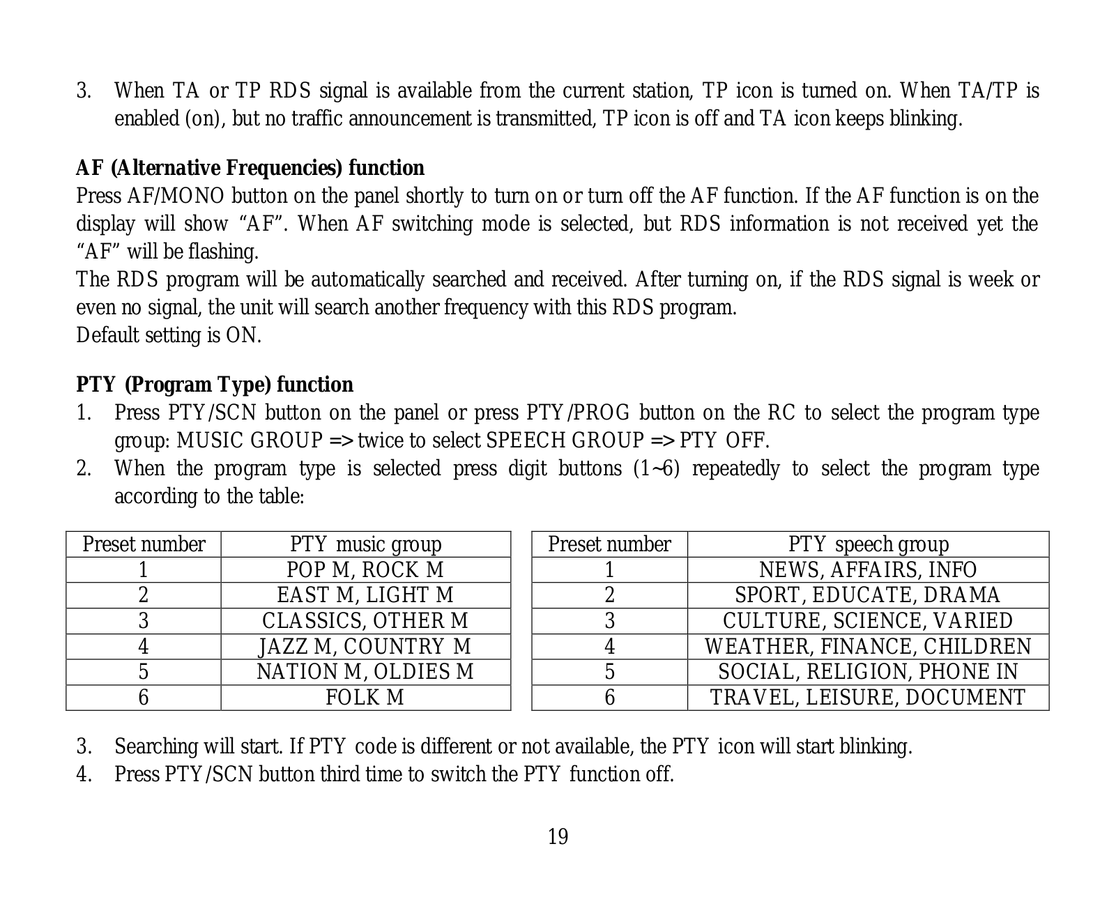
Band selection
Manual/Auto tuning
Programming preset stations
Auto memory store
Preset scan
RDS function
AF (Alternative Frequencies)
function
TA (Traffic Alarm)/TP function
PTY (Program Type)
REG (regional) function
Mono/Stereo control
Local radio station search
Other parameter setting
Disc/USB/SD/MMC operations
USB/SD/MMC notes
Insert/Eject disc
Inserting an SD/MMC card/
USB device
Play/pause
MP3/WMA/DivX/JPEG file playback
Stop playback
Selecting tracks
Fast forward/rewind
A-B segment repeat
Repeat playback
Intro playback
Random playback
Programming playback
OSD function
Zooming in/out
GOTO
Changing angle
Selecting audio language
Selecting subtitle language
Selecting sound channel
PBC function
Menu navigation
ID3 tag information

Notes on MP3 and WMA
Notes on creating your own CD-Rs
or CD-RWs containing MP3 files
System setup
System setup
Language setup
Audio setup
Video setup
Digital setup
General information
Handling compact discs
Cleaning discs
Cleaning the unit body
Accessories
Troubleshooting guide
Specification
2
3
Table of contents
Table of contents
18
19
19
19
19
20
20
20
21
21
21
21
21
22
23

4
Before you start
If you want to dispose this product, do not mix it with general household waste. There is
a separate collection system for used electronic products in accordance with legislation
that requires proper treatment, recovery and recycling.
Please contact your local authorities for the correct method of disposal. By doing so, you
will ensure that your disposed product undergoes the necessary treatment, recovery and
recycling and thus prevent potential negative effects on the environment and human health.
Utilization of the product
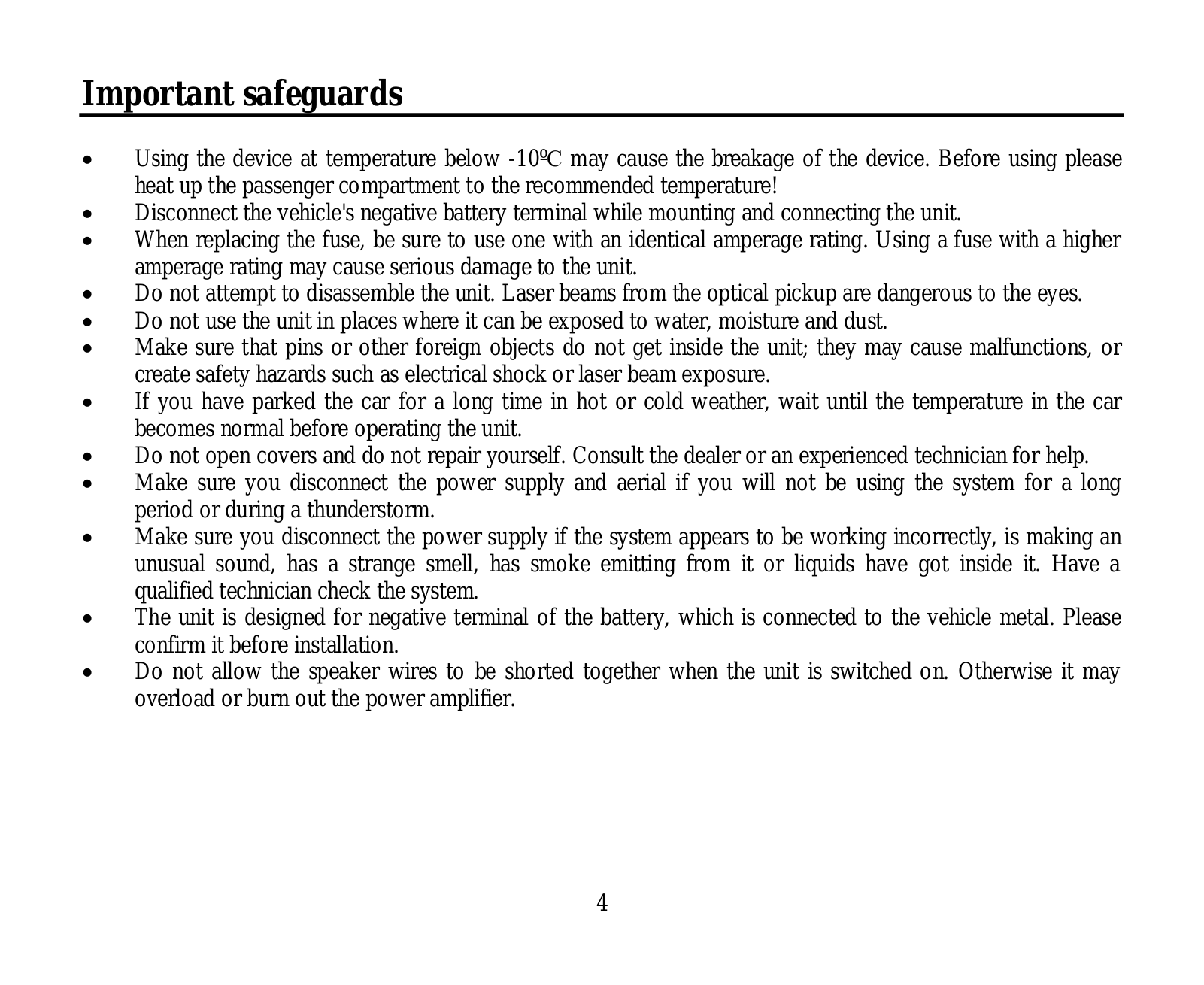
Important safeguards
• Read carefully through the manual to
familiarize yourself with this unit.
• Keep this manual handy as a reference
for operating procedures and precautions. Do
not allow persons who have not read through
this manual to use this unit.
• “CLASS 1 LASER PRODUCT”
This product contains a laser diode of
higher class than 1. Laser beams from the
optical pickup are dangerous to the eyes. To
ensure continued safety, do not remove any
covers or attempt to gain access to the inside
of the product. Refer all servicing to qualified
personnel.
• Do not allow this unit to come into contact
with liquids. Electrical shock could result. Also,
damage to this unit, smoke, and overheating
could result from contact with liquids or dust.
Protect this unit from moisture.
• Make sure that foreign objects do not get
inside the unit; they may cause malfunctions,
or create safety hazards such as electrical
shock or laser beam exposure.
• The beginning of operation is the moment
of the unit installation. Before use the device
in winter it is recommended to heat up the
passenger compartment during 20 seconds or
to the operation temperature.
• Using the unit with the temperature that
goes beyond the operation temperature greatly
decreases the operation resource of the screen
and other components of the unit and can
result in an outage.
• Disconnect the vehicle’s negative battery
terminal while mounting and connecting the
unit.
• The unit is designed for negative
terminal of the battery, which is connected
to the vehicle metal. Please ensure it before
installation.
• When replacing the fuse, be sure to use
one with an identical amperage rating. Using a
fuse with a higher amperage rating may cause
serious damage to the unit.
• Do not allow the speaker wires to be
shorted together when the unit is switched
on. Otherwise it may overload or burn out the
power amplifier.
• Make sure you disconnect the power supply
and aerial if you will not be using the system
for a long period or during a thunderstorm.
• Make sure you disconnect the power supply
if the system appears to be working incorrectly,
is making an unusual sound, has a strange
smell, has smoke emitting from it or liquids
have got inside it. Let a qualified technician
check the system.
• Always keep the volume low enough so that
you can hear sounds from outside the vehicle.
• Should this product fail to operate properly,
contact your dealer or nearest service center.

5
Installation/Connection
Installation
General notes
• Choose the mounting location where the
unit will not interfere with the normal driving
function of the driver.
• Before finally installing the unit, connect
the wiring and make sure that the unit works
properly.
• Consult with your nearest dealer if
installation requires the drilling of holes or other
modifications of the vehicle.
• Install the unit where it does not get in the
driver’s way and cannot injure the passenger if
there is a sudden stop, like an emergency stop.
• If installation angle exceeds 30° from
horizontal, the unit may not perform properly.
• Avoid installing the unit where it would
be subject to high temperature, such as from
direct sunlight, or from hot air, from the heater,
or where it would be subject to dust, dirt or
excessive vibration.
Din Front/Rear-Mount
This unit can be properly installed either
from ‘Front’ (conventional DIN Front-mount) or
‘Rear’ (DIN Rear-mount installation, utilizing
threaded screw Holes at the sides of the unit
chassis). For details, refer to the following
illustrated installation methods.
1. DIN front-mount (Method A)
1. Car dashboard
2. Sleeve
3. Screw
4. Nut (5 mm)
5. Spring washer
6. Screw (5 х 25 mm)
7. Metal strap
8. Flat washer
3
2
1
182
53
1. Install the sleeve into the dashboard;
ensure it is installed with the correct side and
there are no obstacles (wires, dashboard
elements, etc) for the unit installation.
2. After installing the sleeve into the
dashboard, bend tabs fitting to the size of the
dashboard to fix the sleeve in place.
3. Use the metal strap to fix the rear side of
the unit. Determine a place for fixing and install
the strap as shown in the picture. You can bend
the strap to the needed angle with your hands.
4. Make the necessary wire connections.
Ensure the connections are correct.
5. Install the unit into the sleeve until the side
locks are fixed.
3
5
4
6
8
1
7
Dismantling the unit
a – Trim frame
b – Frame uninstall direction
c – Release key insertion

6
Installation/Connection
в
б
а
1. Switch off the unit and detach the front
panel.
2. Insert your fingers into the groove in the
front side of the trim frame (apply some effort to
detach the frame). Pull the frame to detach it.
3. Insert the supplied release keys into the
both sides of the unit body to click, as shown
in the picture. To extract the unit from the
dashboard, pull the release keys or the unit
body to pull it out. Before detaching the unit,
ensure it is not fixed with the metal strap.
Trim frame installation
To install the trim frame, press it to the unit
body and push it to fix it in place. This should
be done before installing the front panel;
otherwise you are not able to install the trim
frame. When the trim frame being installed,
the side with the groove should face down and
fixed first.
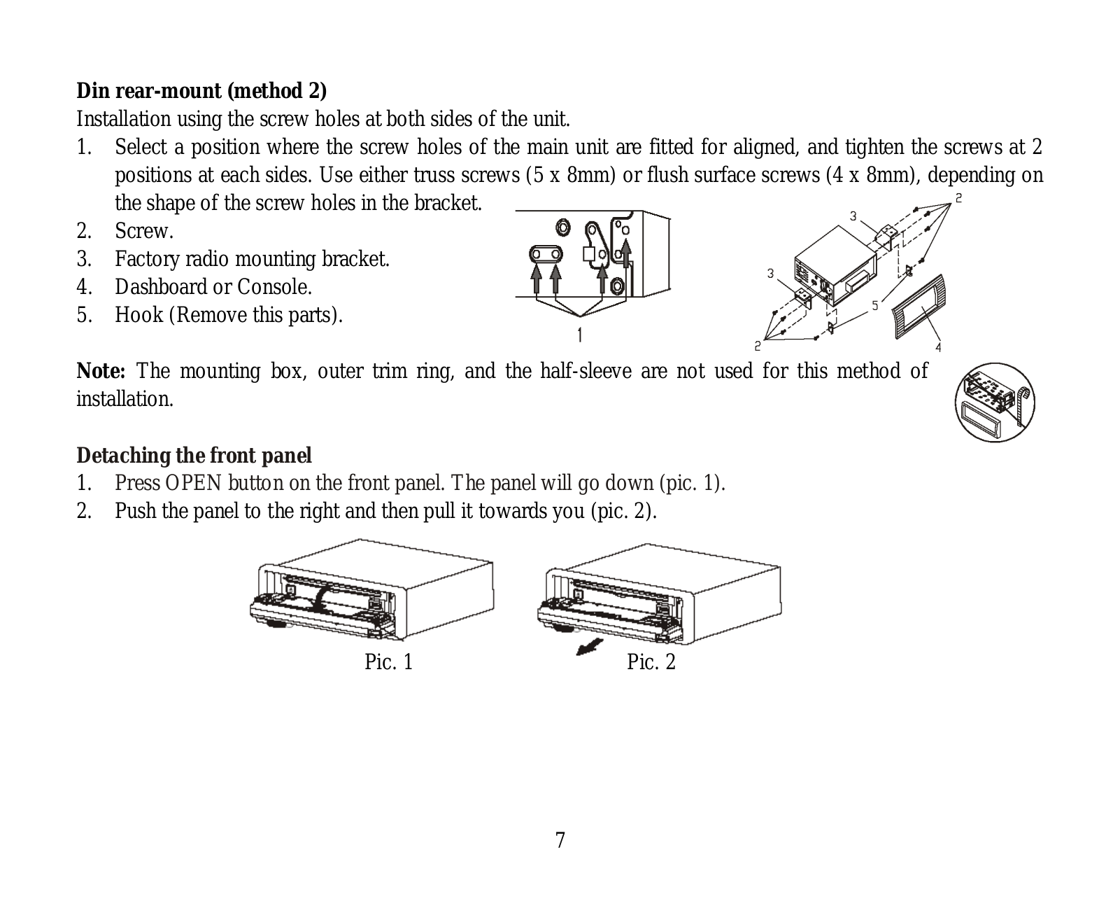
2. DIN rear-mount (Method B)
For this method, use the screw holes in the
lateral sides of the unit. Fix the unit with the
help of the factory radio mounting brackets.
1. Select a position in which the screw holes
of the brackets (3) are aligned with the screw
holes in the unit body, and screw in two screws
(2) in each side.
2. Screw.
3. Factory radio mounting brackets.
4. Vehicle dashboard.
5. Lock (remove this part).
The outer trim frame and mounting
sleeve are not used for method of installation.
2
2
5
5
4
3
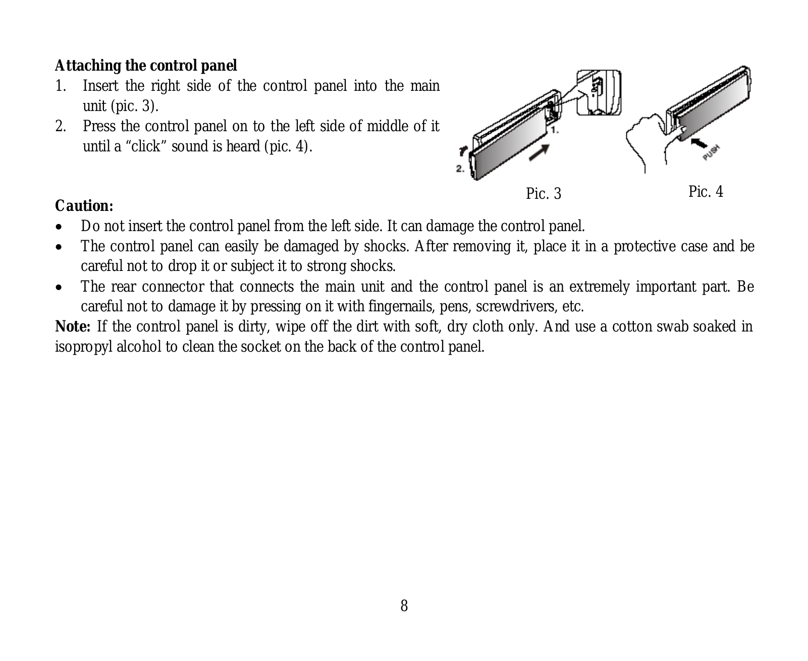
Detachable control panel
Insert the left locker of the body into the fixing
hle on the side of the panel, then insert the right
locker into the right hole of the panel. Press on
the upper part of the panel until a click.
To detach the front panel, press OPEN
button. Hold the panel at 45 degree angle and
push it to the left to detach the right locker.
Then detach the left locker.
The control panel can easily be
damaged by shocks. After removing it, place
it in a protective case and be careful not to
drop it or subject it to strong shocks. The rear
connector that connects the main unit and the
control panel is an extremely important part. Be
careful not to damage it by pressing on it with
fingernails, pens, screwdrivers, etc.
If the control panel is dirty, wipe off the
dirt with soft, dry cloth only. And use a cotton
swab soaked in isopropyl alcohol to clean the
socket on the back of the control panel.
Anti-theft system
The front panel of this unit can be stored in
the included protective case when not in used
and carried away when you leave the vehicle
to deter theft.
Switch off the power of the unit. Detach the
front panel, then put it to the protective case
and take it with you.

7
Installation/Connection
Connection
Connection diagram
Connector A
1. —
2. —
3. —
4. Memory +12V
5. Auto antenna output
6. To dimmer control
7. +12V (to ignition key)
8. Ground
Connector B
1. Rear right speaker (+)
2. Rear right speaker (-)
3. Front right speaker (+)
4. Front right speaker (-)
5. Front left speaker (+)
6. Front left speaker (-)
7. Rear left speaker (+)
8. Rear left speaker (-)
ISO connector
DVD video RCA out (yellow)
Red-Right
Red-Right
Line out
Grey-Front
Line out
Brown-Rear
DVD audio RCA out (white-left)
DVD audio RCA out (red-right)
White-Left
White-Left
Parking (brown)
Subwoofer out (blue)
Antenna jack
ISO connection table
Location
1
2
3
4
5
6
7
8
Connector A
Battery 12V (+)/yellow
Power Antenna/Blue
Dimmer/Orange
ACC+/Red
Ground/Black
Connector B
Rear Right(+)—Violet
Rear Right(-)—Violet/Black Stripe
Front Right(+)—Grey
Front Right(-)—Grey/Black Stripe
Front Left(+)—White
Front Left((-)—White/Black Stripe
Rear Left(+)—Green
Rear Left(-)—Green/Black Stripe
Function
Power antenna wire is intended for power supply of the antenna and for remote control of
an additional amplifier.

8
9
Installation/Connection
Operation
Parking wire connection
Parking brake
Parking brake switch
(activated by parking brake)
To metal body part of chassis body of your car
Parking brake
indicator light
Parking brake wire (brown) from Car DVD player
Car battery
The parking wire is connected with brake signal; for safety, the video programs should only
be viewed after car’s breaks are engaged. Check and follow your local authority’s regulations
regarding watching video in a car.

8
9
Installation/Connection
Operation
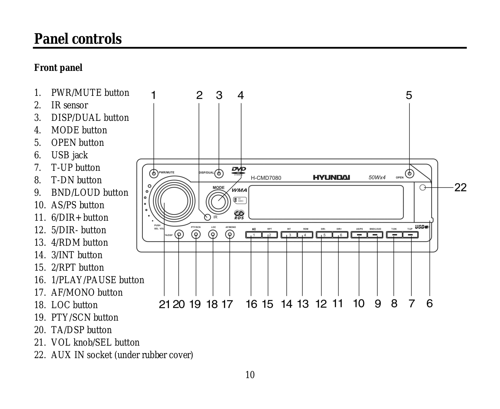
Control elements
Front panel
1. PWR/MUTE button
2. MODE button
3. VOLUME knob
4.
button
5. Display
6. MEM button
1
2
3
4
5
6
7
8
13
12
11
10
9
7. OK button
8. OPEN button
9. USB slot
10. AV in jack
11.
button
12. BAND button
13. MENU button
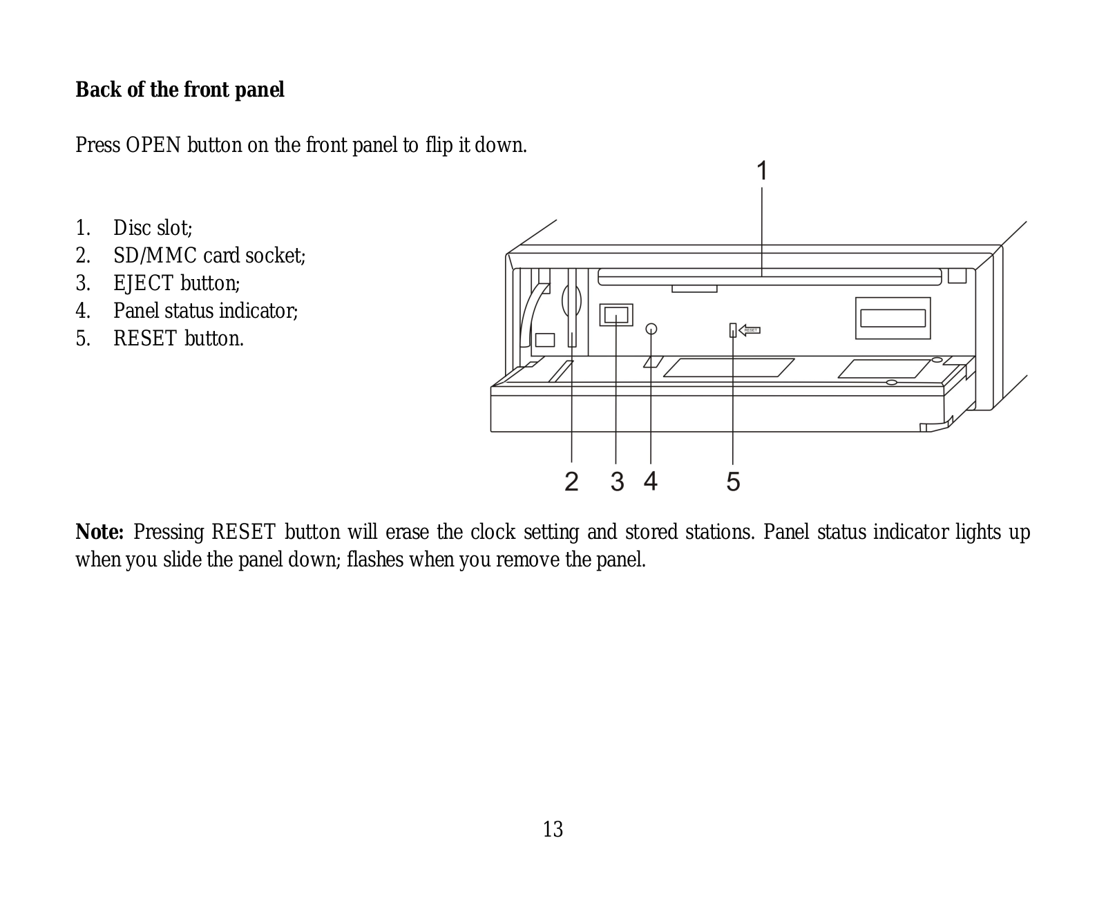
Inner panel
1
2
3
5
4
1. SD/MMC memory card slot
2. EJECT button
3. Panel status indicator
4. RESET button (hole)
5. Disc slot
Pressing RESET hole will erase the
clock setting and stored stations.
Panel status indicator lights up when you
slide the panel down, flashes when you remove
the panel.

10
Operation
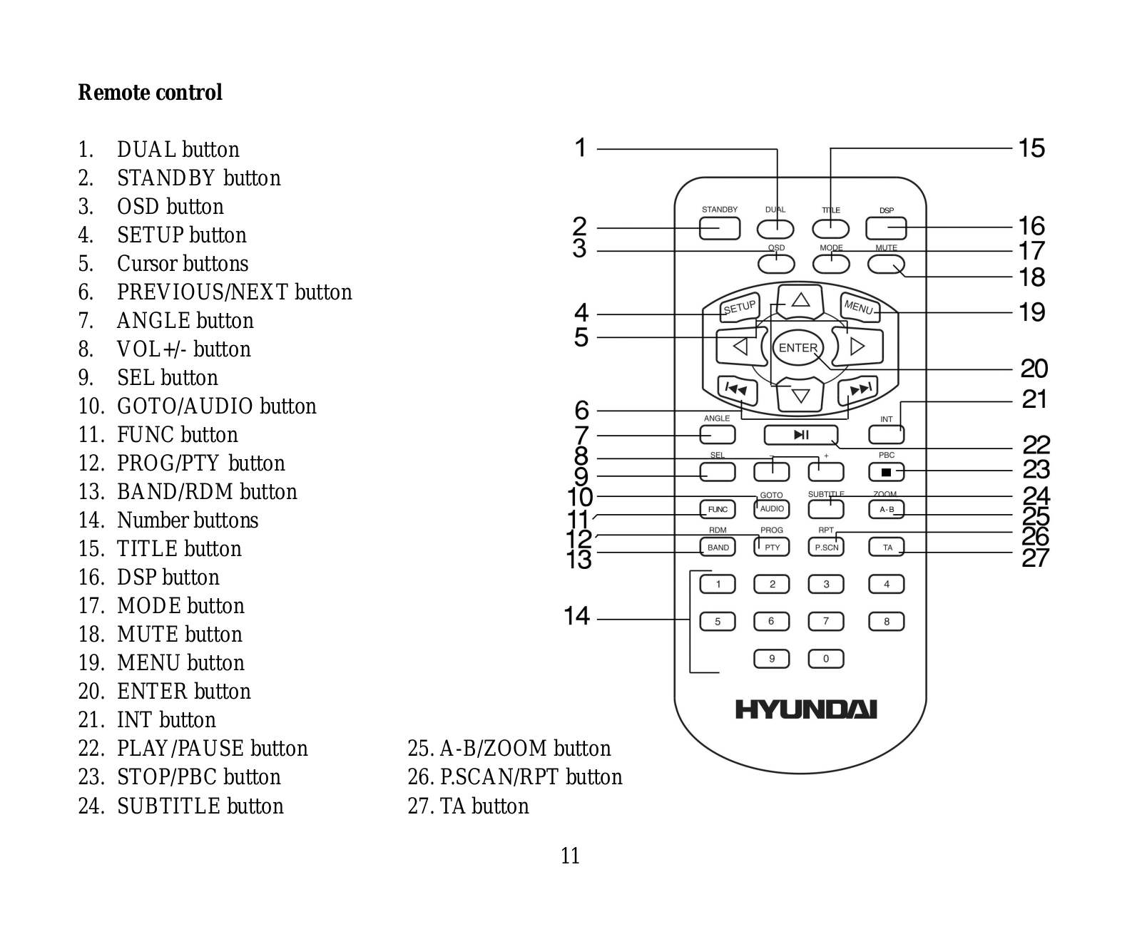
Remote controller
1
2
3
4
5
6
7
8
9
10
11
12
13
14
15
16
17
18
19
20
21
22
23
24
25
26
1. DUAL/DISP button
2. STANDBY button
3. ST/MO button
4. OSD button
5. SETUP button
6. / / / cursor buttons/ENTER button
7.
button
8. ANGLE button
9. VOL+/VOL- button
10. SEL button
11. RDM/BAND button
12. GOTO/AUDIO button
13. Number buttons
14. TITLE button
15. DSP button
16. MUTE button
17. MODE button
18. MENU button
19.
button
20.
button
21. INT button
22. PBC/ button
23. ZOOM/A-B button
24. SUB-T button
25. PROG/PTY button
26. RPT/P.SCN button
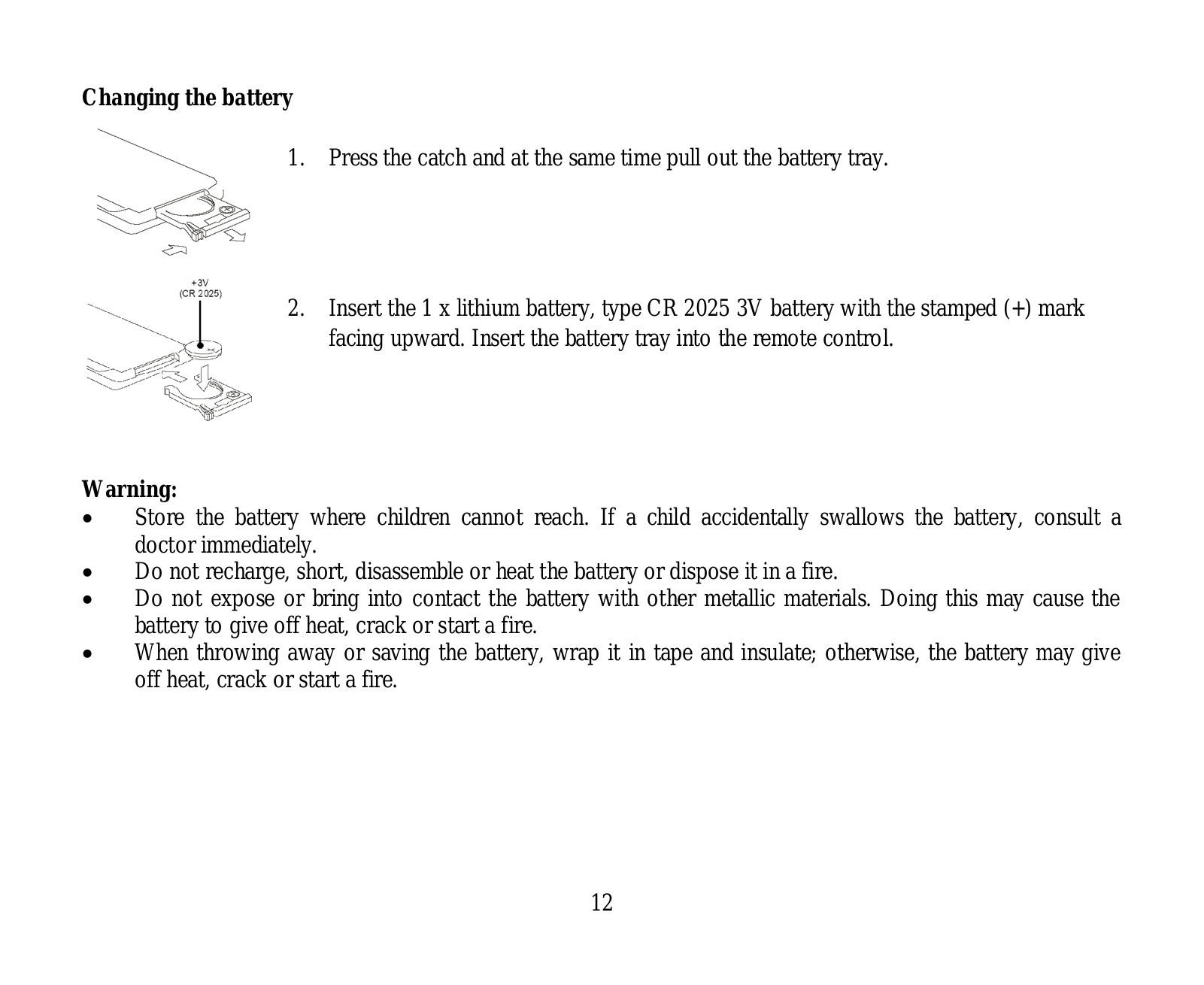
Changing the battery
1. Press the catch and at the same time pull
out the battery tray.
2. Insert the 1 x lithium battery, type CR
2025 3V with (+) mark facing up. Insert the
battery tray into the remote control.

17:48
Hyundai H1 2019 2.5D (170 л.с.) AT Family — видеообзор
10:42
Каша из топора. Ремонт Hyundai H-CDM8048
06:33
Автомагнитола Hyundai H-CCR8187M
13:33
Ремонт автомагнитолы своими руками.Сможет каждый.
03:43
Ремонт магнитолы Hyundai h-cmd4012. Ремонт магнитолы своими руками.
25:48
Что круче? Hyundai H1 VS Citroen SpaceTourer | Выбор есть!
Нажмите на кнопку для помощи
Hyundai
Loading…
H
- H-CDM8068
- H-CDM8069
- H-CDM8075
- H-CDM8092
- H-CDM8092-G
- H-CDM8095
- H-CF 402
- H-CF5022
- H-CH1-1500-UI766
- H-CH1-500-UI765
- H-CMD2000
- H-CMD20022
- H-CMD20032
- H-CMD20052
- H-CMD2007
- H-CMD2009
- H-CMD2009G
- H-CMD2062G
- H-CMD40003
- H-CMD40013
- H-CMD4001G3
- H-CMD40022
- H-CMD4003
- H-CMD4004
- H-CMD40053
- H-CMD40062
- H-CMD40072
- H-CMD40082
- H-CMD4009
- H-CMD4010
- H-CMD40112
- H-CMD4013
- H-CMD4013B
- H-CMD40153
- H-CMD4016
- H-CMD4018
- H-CMD4021
- H-CMD40262
- H-CMD4027
- H-CMD40282
- H-CMD40302
- H-CMD4031
- H-CMD4034
- H-CMD4050G
- H-CMD7070
- H-CMD7073
- H-CMD7074
- H-CMD7075
- H-CMD7076
- H-CMD7079
- H-CMD70802
- H-CMD7082
- H-CMD70832
- H-CMD7084
- H-CMD70862
- H-CMD70872
- H-CMDN6000
- H-CMDN6100
- H-CMMD4040
- H-CMMD40423
- H-CMMD40432
- H-CMMD40443
- H-CMMD40463
- H-CMMD4048
- H-CMMD4048-B
- H-CMMD4049
- H-CMMD40592
- H-CMMD4059G
- H-CSA403
- H-CSA503
- H-CSA604
- H-CSA693
- H-CSB402
- H-CSB502
- H-CSB603
- H-CSB694
- H-CSD402
- H-CSD503
- H-CSD602
- H-CSD603
- H-CSD693
- H-CSD694
- H-CSE4032
- H-CSE5032
- H-CSE 6032
- H-CSE6932
- H-CSE6942
- H-CSF402
- H-CSF602
- H-CSF693
- H-CSG402
- H-CSG502
- H-CSG602
- H-CSG692
- H-CSH402
- H-CSH502
- H-CSH52
- H-CSH602
- H-CSH62
- H-CSJ402
Loading…
Loading…
Nothing found
H-CMD7080
Instruction Manual
49 pgs679.05 Kb0
User Manual
69 pgs1.26 Mb0
Table of contents
Loading…
…
Hyundai User Manual
Download
Specifications and Main Features
Frequently Asked Questions
User Manual

Loading…
+ 48 hidden pages
You need points to download manuals.
1 point = 1 manual.
You can buy points or you can get point for every manual you upload.
Buy points
Upload your manuals
- Инструкции и руководства
- Бренды
- Hyundai
- H-CMD7080
- Справочник Пользователя
EXCELLENCE
by
H-CMD7080
DVD/CD/MP3-RECEIVER
DVD/CD/MP3-
Instruction
manual
- Topics
- manualsbase, manuals,
- Collection
- manuals_hyundai; manuals; additional_collections
- Language
- English
- Item Size
- 22.8M
- Addeddate
- 2020-07-27 04:41:00
- Identifier
- manualsbase-id-127526
- Identifier-ark
- ark:/13960/t9580dx52
- Ocr
- ABBYY FineReader 11.0 (Extended OCR)
- Page_number_confidence
- 100.00
- Ppi
- 300
- Scanner
- Internet Archive Python library 1.9.3
plus-circle Add Review
plus-circle Add Review
comment
Reviews
There are no reviews yet. Be the first one to
write a review.
95
Views
DOWNLOAD OPTIONS
download 1 file
ABBYY GZ download
Temporarily Unavailable
DAISY
For users with print-disabilities
Temporarily Unavailable
EPUB
download 1 file
FULL TEXT download
download 1 file
ITEM TILE download
download 1 file
PAGE NUMBERS JSON download
download 1 file
PDF download
download 1 file
SINGLE PAGE PROCESSED JP2 ZIP download
download 1 file
TORRENT download
download 12 Files
download 6 Original
SHOW ALL
IN COLLECTIONS
Manuals: Hyundai Products
The Manual Library
Additional Collections
Uploaded by
chris85
on