
Manual
View the manual for the HP LaserJet Pro 100 Color MFP M175a here, for free. This user manual comes under the category printers and has been rated by 1 people with an average of a 9.1. This manual is available in the following languages: English. Do you have a question about the HP LaserJet Pro 100 Color MFP M175a?
Ask your question here
Frequently asked questions
Can’t find the answer to your question in the manual? You may find the answer to your question in the FAQs about the HP LaserJet Pro 100 Color MFP M175a below.
What is the best way to remove jammed paper from my printer?
It is best to gently pull the paper out of the printer. Turn the printer off, and make sure that the printhead is not hanging over the paper and that no paper remains in the printer.
How come my prints are of poor quality?
There can be various reasons for poor print quality. Check if the cartridges or toners are full. If so, inkjet printers often require cleaning the printer, the cartridges have dried out, or the print head is broken. With laser printers, calibrating the laser printer is recommended.
How come my printer does not accept original cartridges?
Non-genuine cartridges may not be recognised by the printer. In that case you will receive a message that the cartridge is empty. The manual of the purchased cartridge usually contains the solution, if this does not work, it is advisable to contact the seller.
How come my inkjet printer has black stripes?
In most cases, the inkjet printer cartridge is broken and the cartridge needs to be replaced.
What is the difference between a laser printer and an inkjet printer?
A laser printer prints with a toner and an inkjet printer prints with ink.
What does DPI stand for?
DPI stands for Dots Per Inch and is the number of ink droplets (per inch) that end up on the paper when printing.
Is the manual of the HP LaserJet Pro 100 Color MFP M175a available in English?
Yes, the manual of the HP LaserJet Pro 100 Color MFP M175a is available in English .
Is your question not listed? Ask your question here

LASERJET PRO 100 COLOR MFP M175
Service Manual


HP LaserJet Pro 100 color MFP M175
Service Manual

Copyright and License
Trademark Credits
© 2012 Copyright Hewlett-Packard
Development Company, L.P.
Reproduction, adaptation, or translation
without prior written permission is
prohibited, except as allowed under the
copyright laws.
The information contained herein is subject
to change without notice.
The only warranties for HP products and
services are set forth in the express warranty
statements accompanying such products and
services. Nothing herein should be
construed as constituting an additional
warranty. HP shall not be liable for technical
or editorial errors or omissions contained
herein.
Part number: CE866-90936
Edition 1, 7/2012
Microsoft®, Windows®, Windows® XP,
and Windows Vista® are U.S. registered
trademarks of Microsoft Corporation.

Conventions used in this guide
TIP: Tips provide helpful hints or shortcuts.
NOTE: Notes provide important information to explain a concept or to complete a task.
CAUTION: Cautions indicate procedures that you should follow to avoid losing data or damaging
the product.
WARNING! Warnings alert you to specific procedures that you should follow to avoid personal
injury, catastrophic loss of data, or extensive damage to the product.
ENWW iii

iv Conventions used in this guide ENWW

Table of contents
1 Removal and replacement …………………………………………………………………………………… 1
Introduction …………………………………………………………………………………………………………….. 2
Removal and replacement strategy ………………………………………………………………………………… 2
Electrostatic discharge ……………………………………………………………………………………………….. 3
Required tools ………………………………………………………………………………………………………….. 3
Service approach ……………………………………………………………………………………………………… 4
Before performing service ……………………………………………………………………………… 4
After performing service ………………………………………………………………………………… 4
Post-service test …………………………………………………………………………………………… 4
Product verification test ……………………………………………………………………. 4
Parts removal order ……………………………………………………………………………………… 5
Removal and replacement procedures ……………………………………………………………………………. 7
Print cartridges ……………………………………………………………………………………………. 7
Imaging drum …………………………………………………………………………………………….. 9
Input tray ………………………………………………………………………………………………… 11
Secondary transfer roller ……………………………………………………………………………… 12
Separation pad assembly …………………………………………………………………………….. 13
Pickup roller …………………………………………………………………………………………….. 14
Remove the pickup roller assembly ……………………………………………………. 15
Covers and document feeder ………………………………………………………………………… 16
Right cover …………………………………………………………………………………. 16
Left cover …………………………………………………………………………………… 17
Document feeder ………………………………………………………………………….. 18
Remove the document feeder ……………………………………………… 18
Document feeder hinges …………………………………………………………………. 21
Remove the document feeder hinges …………………………………….. 21
Top door, rear-top cover, and delivery cover ……………………………………….. 22
Remove the top door, rear-top cover, and delivery cover ……………. 22
Reinstall the top door, rear-top cover, and delivery cover …………… 25
Rear door assembly ………………………………………………………………………. 27
Remove the rear door assembly ………………………………………….. 27
Rear-lower cover ………………………………………………………………………….. 28
ENWW v

Remove the rear-lower cover ………………………………………………. 28
Control panel ……………………………………………………………………………… 29
Remove the control panel ………………………………………………….. 29
Left-front cover …………………………………………………………………………….. 31
Remove the left-front cover …………………………………………………. 31
Front door ………………………………………………………………………………….. 33
Remove the front door ………………………………………………………. 33
Inner cover …………………………………………………………………………………. 35
Remove the inner cover …………………………………………………….. 35
Main assemblies ……………………………………………………………………………………….. 38
Formatter PCA (base model) ……………………………………………………………. 38
Remove the formatter PCA (base model) ………………………………… 38
Formatter and wireless PCA (plus model) …………………………………………….. 40
Remove the formatter and wireless PCA (plus model) ………………… 40
Fuser power supply ………………………………………………………………………. 42
Remove the fuser power supply …………………………………………… 42
ITB assembly ……………………………………………………………………………….. 43
Remove the ITB assembly …………………………………………………… 43
Fuser delivery assembly …………………………………………………………………. 53
Remove the fuser delivery assembly ……………………………………… 54
Engine controller assembly ……………………………………………………………… 58
Remove the engine controller assembly …………………………………. 58
Low-voltage power supply assembly ………………………………………………….. 63
Remove the low-voltage power supply assembly ………………………. 63
Document feeder components ……………………………………………………………………….. 69
Document feeder input tray ……………………………………………………………… 69
Document feeder cover ………………………………………………………………….. 70
Document feeder core ……………………………………………………………………. 72
Remove the document feeder core ……………………………………….. 72
Post scan pinch rollers …………………………………………………………………… 74
Remove the post scan pinch rollers ………………………………………. 74
Document feeder base assembly ………………………………………………………. 75
Remove the document feeder base assembly ………………………….. 75
2 Solve problems ………………………………………………………………………………………………… 77
Solve problems checklist …………………………………………………………………………………………… 78
Step 1: Test print functionality ……………………………………………………………………….. 78
Step 2: Test copy functionality ………………………………………………………………………. 78
Menu map ……………………………………………………………………………………………………………. 79
Troubleshooting processes …………………………………………………………………………………………. 80
Determine the problem source ……………………………………………………………………….. 80
vi ENWW

Power subsystem ……………………………………………………………………………………….. 81
Power-on checks ………………………………………………………………………….. 81
Tools for troubleshooting …………………………………………………………………………………………… 82
Component diagnostics ……………………………………………………………………………….. 82
Component tests …………………………………………………………………………… 82
Control-panel tests …………………………………………………………… 82
Diagrams ………………………………………………………………………………………………… 83
Locations of connectors ………………………………………………………………….. 83
Locations of major components ………………………………………………………… 84
General timing chart ……………………………………………………………………… 86
General circuit diagram …………………………………………………………………. 87
Internal print-quality test pages ………………………………………………………………………. 88
Print a Diagnostics Page ………………………………………………………………… 88
Interpret the Print Quality Page …………………………………………………………. 89
Print-quality troubleshooting tools …………………………………………………………………… 90
Repetitive image defects ruler ………………………………………………………….. 90
Calibrate the product …………………………………………………………………….. 90
Control panel menus …………………………………………………………………………………… 91
Setup menu ………………………………………………………………………………… 91
Reports menu …………………………………………………………………. 91
System Setup menu ………………………………………………………….. 91
Service menu …………………………………………………………………. 94
Network Setup menu (network models only) …………………………… 94
Function specific menus ………………………………………………………………….. 95
Copy Menu …………………………………………………………………… 95
Service mode functions …………………………………………………………………………………………….. 97
Service menu/Secondary service menu ……………………………………………………………. 97
Service menu ………………………………………………………………………………. 97
Secondary service menu ………………………………………………………………… 97
Open the secondary service menu ……………………………………….. 97
Secondary service menu structure ………………………………………… 98
Product resets …………………………………………………………………………………………… 99
Restore factory settings …………………………………………………………………… 99
NVRAM initialization …………………………………………………………………….. 99
Product updates ……………………………………………………………………………………………………… 99
3 Parts and diagrams ………………………………………………………………………………………… 101
Order parts by authorized service providers …………………………………………………………………. 102
Order replacement parts ……………………………………………………………………………. 102
Related documentation and software …………………………………………………………….. 102
Supplies part numbers ………………………………………………………………………………. 102
ENWW vii

Service parts ………………………………………………………………………………………….. 103
Whole-unit replacement part numbers ……………………………………………………………. 103
How to use the parts lists and diagrams ………………………………………………………………………. 104
Assembly locations ………………………………………………………………………………………………… 105
Base product (no optional trays or accessories) ………………………………………………… 105
Covers, panels, and doors ………………………………………………………………………………………. 106
Internal assembly ………………………………………………………………………………………………….. 108
Internal assembly …………………………………………………………………………………….. 108
PCAs …………………………………………………………………………………………………………………. 110
Scanner and document feeder (ADF) main assemblies …………………………………………………….. 112
Document feeder internal components ………………………………………………………………………… 114
Alphabetical parts list …………………………………………………………………………………………….. 116
Numerical parts list ……………………………………………………………………………………………….. 119
Appendix A Service and support …………………………………………………………………………. 123
Hewlett-Packard limited warranty statement ………………………………………………………………….. 124
HP’s Premium Protection Warranty: LaserJet print cartridge limited warranty statement ……………… 126
HP’s LaserJet imaging drum limited warranty statement for replacement imaging drums ……………. 127
Data stored on the print cartridge and imaging drum ……………………………………………………… 128
End User License Agreement …………………………………………………………………………………….. 129
OpenSSL …………………………………………………………………………………………………………….. 132
Customer self-repair warranty service …………………………………………………………………………. 133
Customer support ………………………………………………………………………………………………….. 133
Repack the product ……………………………………………………………………………………………….. 134
Appendix B Specifications …………………………………………………………………………………… 135
Physical specifications ……………………………………………………………………………………………. 136
Power consumption, electrical specifications, and acoustic emissions …………………………………… 136
Environmental specifications …………………………………………………………………………………….. 136
Appendix C Regulatory information ……………………………………………………………………… 137
FCC regulations ……………………………………………………………………………………………………. 138
Declaration of conformity (base models) ……………………………………………………………………… 139
Declaration of conformity (wireless models) ………………………………………………………………….. 141
Certificate of Volatility ……………………………………………………………………………………………. 143
Safety statements ………………………………………………………………………………………………….. 144
Laser safety ……………………………………………………………………………………………. 144
Canadian DOC regulations ………………………………………………………………………… 144
VCCI statement (Japan) ……………………………………………………………………………… 144
Power cord instructions ……………………………………………………………………………… 144
viii ENWW

Power cord statement (Japan) ……………………………………………………………………… 144
EMC statement (Korea) ……………………………………………………………………………… 145
Laser statement for Finland …………………………………………………………………………. 145
GS statement (Germany) ……………………………………………………………………………. 145
Substances Table (China) …………………………………………………………………………… 146
Restriction on Hazardous Substances statement (Turkey) ……………………………………… 146
Additional statements for wireless products …………………………………………………………………… 147
FCC compliance statement—United States ………………………………………………………. 147
Australia statement …………………………………………………………………………………… 147
Brazil ANATEL statement ……………………………………………………………………………. 147
Canadian statements ………………………………………………………………………………… 147
European Union regulatory notice ………………………………………………………………… 147
Notice for use in France …………………………………………………………………………….. 148
Notice for use in Russia …………………………………………………………………………….. 148
Korean statement …………………………………………………………………………………….. 148
Taiwan statement …………………………………………………………………………………….. 149
Index ………………………………………………………………………………………………………………. 151
ENWW ix

x ENWW

List of tables
Table 2-1 External covers and doors (base) ……………………………………………………………………………….. 85
Table 2-2 Service menu ……………………………………………………………………………………………………… 97
Table 2-3 Secondary service menu ………………………………………………………………………………………….. 98
Table 3-1 Order parts, accessories, and supplies ………………………………………………………………………. 102
Table 3-2 Related documentation and software ………………………………………………………………………… 102
Table 3-3 Supplies part numbers …………………………………………………………………………………………… 102
Table 3-4 Whole-unit replacement part numbers ……………………………………………………………………….. 103
Table 3-5 Base product ……………………………………………………………………………………………………… 105
Table 3-6 Covers, panels, and doors ……………………………………………………………………………………… 107
Table 3-7 Internal assembly) ………………………………………………………………………………………………… 109
Table 3-8 PCAs ……………………………………………………………………………………………………………….. 111
Table 3-9 Scanner and document feeder main assemblies …………………………………………………………… 113
Table 3-10 Document feeder assembly parts ……………………………………………………………………………. 115
Table 3-11 Alphabetical parts list …………………………………………………………………………………………. 116
Table 3-12 Numerical parts list …………………………………………………………………………………………….. 1 1 9
Table B-1 Physical specifications
Table B-2 Environmental specifications …………………………………………………………………………………… 136
1
………………………………………………………………………………………….. 136
ENWW xi

xii ENWW

List of figures
Figure 1-1 Phillips and Pozidriv screwdriver comparison …………………………………………………………………. 3
Figure 1-2 Parts removal order (base) ………………………………………………………………………………………… 5
Figure 1-3 Parts removal order (document feeder) …………………………………………………………………………. 6
Figure 1-4 Remove the tray …………………………………………………………………………………………………… 11
Figure 1-5 Remove the secondary transfer roller ………………………………………………………………………….. 12
Figure 1-6 Remove the separation pad assembly (1 of 1) ………………………………………………………………. 13
Figure 1-7 Remove the pickup roller assembly (1 of 2) ………………………………………………………………….. 15
Figure 1-8 Remove the pickup roller assembly (2 of 2) ………………………………………………………………….. 15
Figure 1-9 Remove the right cover (1 of 2) ………………………………………………………………………………… 16
Figure 1-10 Remove the right cover (2 of 2) ………………………………………………………………………………. 16
Figure 1-11 Remove the left cover (1 of 2) ………………………………………………………………………………… 17
Figure 1-12 Remove the left cover (2 of 2) ………………………………………………………………………………… 17
Figure 1-13 Remove the document feeder (1 of 4) ……………………………………………………………………….. 18
Figure 1-14 Remove the document feeder (2 of 4) ……………………………………………………………………….. 19
Figure 1-15 Remove the document feeder (3 of 4) ……………………………………………………………………….. 19
Figure 1-16 Remove the document feeder (4 of 4) ……………………………………………………………………….. 20
Figure 1-17 Remove the scanner hinges (1 of 2) …………………………………………………………………………. 21
Figure 1-18 Remove the scanner hinges (2 of 2) …………………………………………………………………………. 21
Figure 1-19 Remove the top door, rear-top cover, and delivery cover (1 of 6) …………………………………….. 22
Figure 1-20 Remove the top door, rear-top cover, and delivery cover (2 of 6) …………………………………….. 23
Figure 1-21 Remove the top door, rear-top cover, and delivery cover (3 of 6) …………………………………….. 23
Figure 1-22 Remove the top door, rear-top cover, and delivery cover (4 of 6) …………………………………….. 24
Figure 1-23 Remove the top door, rear-top cover, and delivery cover (5 of 6) …………………………………….. 24
Figure 1-24 Remove the top door, rear-top cover, and delivery cover (6 of 6) …………………………………….. 25
Figure 1-25 Reinstall the top door, rear-top cover, and delivery cover (1 of 2) …………………………………….. 25
Figure 1-26 Reinstall the top door, rear-top cover, and delivery cover (1 of 2) …………………………………….. 26
Figure 1-27 Remove the rear door assembly (1 of 2) ……………………………………………………………………. 27
Figure 1-28 Remove the rear door assembly (2 of 2) ……………………………………………………………………. 27
Figure 1-29 Remove the rear-lower cover ………………………………………………………………………………….. 28
Figure 1-30 Remove the control panel (1 of 3) ……………………………………………………………………………. 29
Figure 1-31 Remove the control panel (2 of 3) ……………………………………………………………………………. 30
Figure 1-32 Remove the control panel (3 of 3) ……………………………………………………………………………. 30
ENWW xiii

Figure 1-33 Remove the left-front cover (1 of 2) ………………………………………………………………………….. 31
Figure 1-34 Remove the left-front cover (2 of 2) ………………………………………………………………………….. 32
Figure 1-35 Remove the front door (1 of 2) ……………………………………………………………………………….. 33
Figure 1-36 Remove the front door (2 of 3) ……………………………………………………………………………….. 34
Figure 1-37 Remove the inner cover (1 of 4) ……………………………………………………………………………… 35
Figure 1-38 Remove the inner cover (2 of 4) ……………………………………………………………………………… 36
Figure 1-39 Remove the inner cover (3 of 4) ……………………………………………………………………………… 36
Figure 1-40 Remove the inner cover (4 of 4) ……………………………………………………………………………… 37
Figure 1-41 Remove the formatter PCA (base model; 1 of 2) ………………………………………………………….. 38
Figure 1-42 Remove the formatter PCA (base model; 2 of 2) ………………………………………………………….. 39
Figure 1-43 Remove the formatter and wireless PCA (plus model; 1 of 3) …………………………………………… 40
Figure 1-44 Remove the formatter and wireless PCA (plus mode; 2 of 3) …………………………………………… 40
Figure 1-45 Remove the formatter and wireless PCA (plus mode; 3 of 3) …………………………………………… 41
Figure 1-46 Remove the fuser power supply (1 of 2) ……………………………………………………………………. 42
Figure 1-47 Remove the fuser power supply (2 of 2) ……………………………………………………………………. 42
Figure 1-48 Remove the ITB assembly (1 of 17) ………………………………………………………………………….. 43
Figure 1-49 Remove the ITB assembly (2 of 17) ………………………………………………………………………….. 44
Figure 1-50 Remove the ITB assembly (3 of 17) ………………………………………………………………………….. 44
Figure 1-51 Remove the ITB assembly (4 of 17) ………………………………………………………………………….. 45
Figure 1-52 Remove the ITB assembly (5 of 17) ………………………………………………………………………….. 45
Figure 1-53 Remove the ITB assembly (6 of 17) ………………………………………………………………………….. 46
Figure 1-54 Remove the ITB assembly (7 of 17) ………………………………………………………………………….. 46
Figure 1-55 Remove the ITB assembly (8 of 17) ………………………………………………………………………….. 47
Figure 1-56 Remove the ITB assembly (9 of 17) ………………………………………………………………………….. 48
Figure 1-57 Remove the ITB assembly (10 of 17) ………………………………………………………………………… 48
Figure 1-58 Remove the ITB assembly (11 of 17) ………………………………………………………………………… 49
Figure 1-59 Remove the ITB assembly (12 of 17) ………………………………………………………………………… 49
Figure 1-60 Remove the ITB assembly (13 of 17) ………………………………………………………………………… 50
Figure 1-61 Remove the ITB assembly (14 of 17) ………………………………………………………………………… 50
Figure 1-62 Remove the ITB assembly (15 of 17) ………………………………………………………………………… 51
Figure 1-63 Remove the ITB assembly (16 of 17) ………………………………………………………………………… 51
Figure 1-64 Remove the ITB assembly (17 of 17) ………………………………………………………………………… 52
Figure 1-65 Remove the fuser delivery assembly (1 of 6) ……………………………………………………………….. 54
Figure 1-66 Remove the fuser delivery assembly (2 of 6) ……………………………………………………………….. 54
F
gure 1-67 Remove the fuser delivery assembly (3 of 6) ……………………………………………………………….. 55
i
Figure 1-68 Remove the fuser delivery assembly (4 of 6) ……………………………………………………………….. 55
Figure 1-69 Remove the fuser delivery assembly (5 of 6) ……………………………………………………………….. 56
Figure 1-70 Remove the fuser delivery assembly (6 of 6) ……………………………………………………………….. 56
Figure 1-71 Reinstall the fuser delivery assembly (1 of 2) ………………………………………………………………. 57
Figure 1-72 Reinstall the fuser delivery assembly (2 of 2) ………………………………………………………………. 57
Figure 1-73 Remove the engine controller assembly (1 of 7) …………………………………………………………… 58
xiv ENWW

Figure 1-74 Remove the engine controller assembly (2 of 7) …………………………………………………………… 59
Figure 1-75 Remove the engine controller assembly (3 of 7) …………………………………………………………… 59
Figure 1-76 Remove the engine controller assembly (4 of 7) …………………………………………………………… 60
Figure 1-77 Remove the engine controller assembly (5 of 7) …………………………………………………………… 60
Figure 1-78 Remove the engine controller assembly (6 of 7) …………………………………………………………… 61
Figure 1-79 Remove the engine controller assembly (7 of 7) …………………………………………………………… 61
Figure 1-80 Installing a replacement engine controller assembly ……………………………………………………… 62
Figure 1-81 Remove the low-voltage power supply assembly (1 of 9) ……………………………………………….. 63
Figure 1-82 Remove the low-voltage power supply assembly (2 of 9) ……………………………………………….. 64
Figure 1-83 Remove the low-voltage power supply assembly (3 of 9) ……………………………………………….. 64
Figure 1-84 Remove the low-voltage power supply assembly (4 of 9) ……………………………………………….. 65
Figure 1-85 Remove the low-voltage power supply assembly (5 of 9) ……………………………………………….. 65
Figure 1-86 Remove the low-voltage power supply assembly (6 of 9) ……………………………………………….. 66
Figure 1-87 Remove the low voltage power supply assembly (7 of 9) ……………………………………………….. 66
Figure 1-88 Remove the low-voltage power supply assembly (8 of 9) ……………………………………………….. 67
Figure 1-89 Remove the low-voltage power supply assembly (9 of 9) ……………………………………………….. 67
Figure 1-90 Reinstall the low-voltage power supply ……………………………………………………………………… 68
Figure 1-91 Installing a replacement low-voltage power supply ………………………………………………………. 68
Figure 1-92 Remove the document feeder input tray (1 of 2) ………………………………………………………….. 69
Figure 1-93 Remove the document feeder input tray (2 of 2) ………………………………………………………….. 69
Figure 1-94 Remove the document feeder cover (1 of 3) ……………………………………………………………….. 70
Figure 1-95 Remove the document feeder cover (2 of 3) ……………………………………………………………….. 70
Figure 1-96 Remove the document feeder cover (3 of 3) ……………………………………………………………….. 71
Figure 1-97 Remove the document feeder core (1 of 4) ………………………………………………………………… 72
Figure 1-98 Remove the document feeder core (2 of 4) ………………………………………………………………… 72
Figure 1-99 Remove the document feeder core (3 of 4) ………………………………………………………………… 73
Figure 1-100 Remove the document feeder core (4 of 4) ………………………………………………………………. 73
Figure 1-101 Remove the post scan pinch rollers ………………………………………………………………………… 74
Figure 1-102 Remove the document feeder base assembly (1 of 3) ………………………………………………….. 75
Figure 1-103 Remove the document feeder base assembly (2 of 3) ………………………………………………….. 76
Figure 1-104 R
ure 2-1 Locations of connectors ………………………………………………………………………………………….. 83
Fig
Figure 2-2 Cross section view ………………………………………………………………………………………………… 84
Figure 2-3 External covers and doors (base) ………………………………………………………………………………. 85
Figure 2-4 General timing diagram …………………………………………………………………………………………. 86
Figure 2-5 General circuit diagram …………………………………………………………………………………………. 87
Figure 2-6 Diagnostics Page ………………………………………………………………………………………………….. 88
Figure 3-1 Base product (no optional trays or accessories) …………………………………………………………… 105
Figure 3-2 Covers, panels, and doors ……………………………………………………………………………………. 106
Figure 3-3 Internal assembly ………………………………………………………………………………………………… 108
Figure 3-4 PCAs ………………………………………………………………………………………………………………. 110
emove the document feeder base assembly (3 of 3) ………………………………………………….. 76
ENWW xv

Figure 3-5 Scanner and document feeder main assemblies ………………………………………………………….. 112
Figure 3-6 Document feeder assembly parts …………………………………………………………………………….. 114
xvi ENWW

1 Removal and replacement
Introduction
●
Removal and replacement strategy
●
Electrostatic discharge
●
Required tools
●
Service approach
●
Removal and replacement procedures
●
ENWW 1

Introduction
This chapter describes the removal and replacement of field-replaceable units (FRUs) only.
Replacing FRUs is generally the reverse of removal. Occasionally, notes and tips are included to
provide directions for difficult or critical replacement procedures.
HP does not support repairing individual subassemblies or troubleshooting to the component level.
Note the length, diameter, color, type, and location of each screw. Be sure to return each screw to its
original location during reassembly.
Incorrectly routed or loose wire harnesses can interfere with other internal components and can become
damaged or broken. Frayed or pinched harness wires can be difficult to find. When replacing wire
harnesses, always use the provided wire loops, lance points, or wire-harness guides and retainers.
Removal and replacement strategy
WARNING! Turn the product off, wait 5 seconds, and then remove the power cord before
attempting to service the product. If this warning is not followed, severe injury can result, in addition to
damage to the product. The power must be on for certain functional checks during troubleshooting.
However, disconnect the power supply during parts removal.
Never operate or service the product with the protective cover removed from the laser/scanner
assembly. The reflected beam, although invisible, can damage your eyes.
The sheet-metal parts can have sharp edges. Be careful when handling sheet-metal parts.
CAUTION: Do not bend or fold the flat flexible cables (FFCs) during removal or installation. Also, do
not straighten pre-folds in the FFCs. You must fully seat all FFCs in their connectors. Failure to fully seat
an FFC into a connector can cause a short circuit in a PCA.
NOTE: To install a self-tapping screw, first turn it counterclockwise to align it with the existing thread
pattern, and then carefully turn it clockwise to tighten. Do not overtighten. If a self-tapping screw-hole
becomes stripped, repair the screw-hole or replace the affected assembly.
TIP: For clarity, some photos in this chapter show components removed that would not be removed to
service the product. If necessary, remove the components listed at the beginning of a procedure before
proceeding to service the product.
2 Chapter 1 Removal and replacement ENWW
Electrostatic discharge
CAUTION: Some parts are sensitive to electrostatic discharge (ESD). Look for the ESD reminder
when removing product parts. Always perform service work at an ESD-protected workstation or mat, or
use an ESD strap. If an ESD workstation, mat, or strap is not available, ground yourself by touching the
sheet-metal chassis before touching an ESD-sensitive part.
Protect the ESD-sensitive parts by placing them in ESD pouches when they are out of the product.
Required tools
#2 Phillips screwdriver with a magnetic tip and a 152-mm (6-inch) shaft length
●
Small flat-blade screwdriver
●
Needle-nose pliers
●
ESD mat (if one is available) or ESD strap
●
Penlight (optional)
●
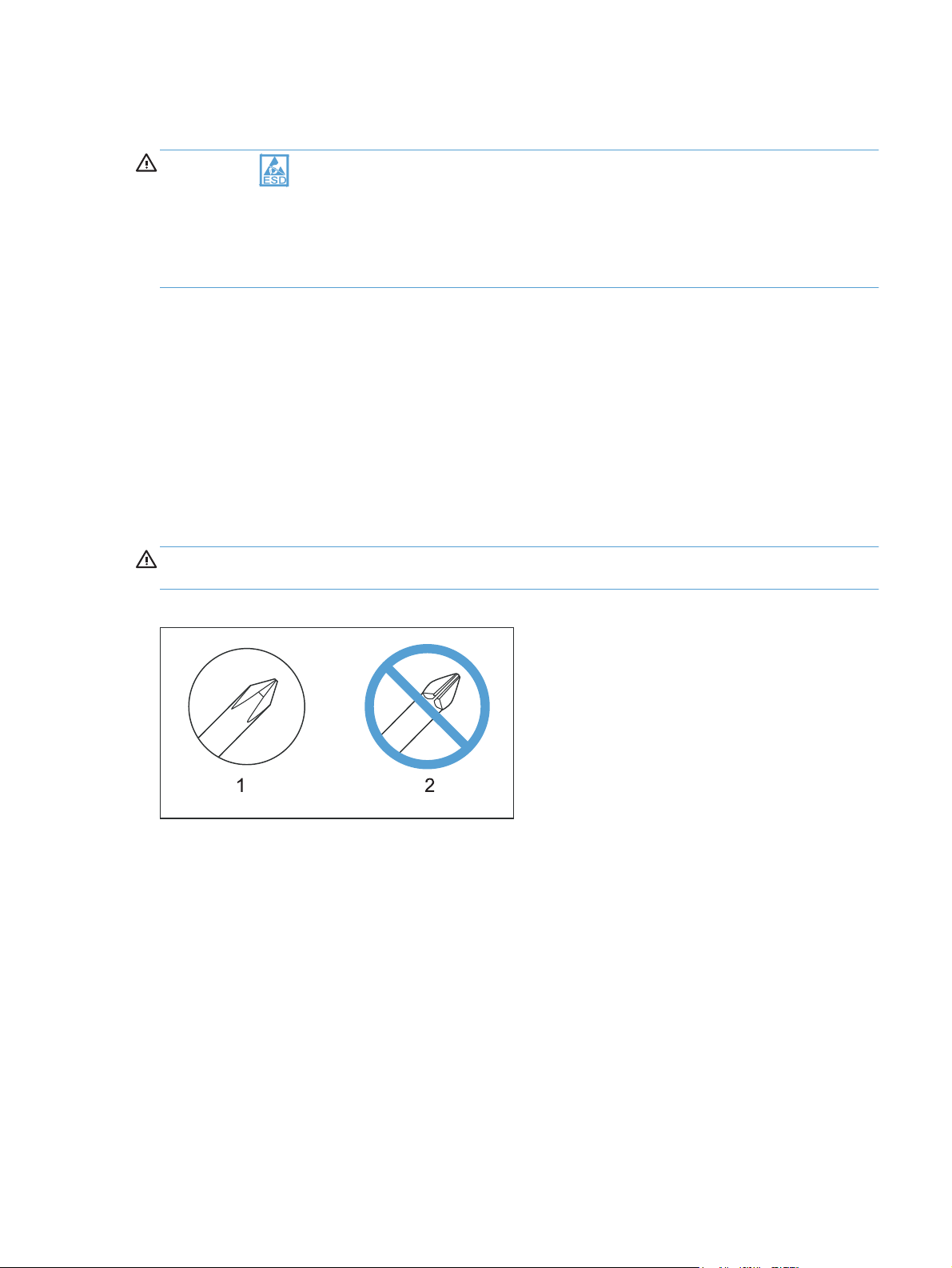
CAUTION: Always use a Phillips screwdriver (callout 1). Do not use a Pozidriv screwdriver
(callout 2) or any motorized screwdriver. These can damage screws or screw threads.
Figure 1-1 Phillips and Pozidriv screwdriver comparison
ENWW
Electrostatic discharge
3

Service approach
Before performing service
Remove all paper from the product.
●
Turn off the power using the power button.
●
WARNING! The power button must be turned off before performing service. Failure to turn off
the power leaves the fuser engaged and prevents its removal.
Unplug the power cable and interface cable or cables.
●
Place the product on an ESD workstation or mat (if one is available), or use an ESD strap. If an
●
ESD workstation, mat, or strap is not available, ground yourself by touching the sheet-metal
chassis before touching an ESD-sensitive part.
Remove the print cartridges and imaging drum. See
●
drum on page 9
Remove the input tray. See
●
After performing service
Plug in the power cable.
●
Reinstall the print cartridges.
●
Load paper in the product.
●
Post-service test
Perform the following test to verify that the repair or replacement was successful.
Product verification test
1. Verify that you have completed the necessary reassembly steps.
2. Make sure that the tray contains clean, unmarked paper.
3. Attach the power cord and interface cable or interface cables, and then turn on the product.
Print cartridges on page 7 and Imaging
Input tray on page 11.
4. Verify that the expected startup sounds occur.
5. Print a configuration page, and then verify that the expected printing sounds occur.
6. Send a print job from the host computer, and then verify that the output meets expectations.
7. Use the document feeder to make a copy.
8. Clean the outside of the product with a damp cloth.
4 Chapter 1 Removal and replacement ENWW

Parts removal order
Figure 1-2 Parts removal order (base)
Print cartridges
Imaging drum
Input tray
Secondary
transfer roller
Separation pad
Pickup roller
Right cover assembly
Left cover assembly
Document feeder
Document feeder
hinges
Separation
pad
Left cover
Left cover
Right cover
Document
feeder
Left cover
Top door, rear cover,
and delivery cover
Rear door assembly
Rear-lower cover
Control Panel
Left-front cover
Front door
Inner cover
Formatter PCA
(base model)
Formatter and
wireless PCA
(plus model)
Fuser power supply
ITB
Fuser delivery
assembly
Engine controller
assembly
Low-voltage power
supply assembly
Right cover
Right cover
Right cover
Right cover
Right cover
Right cover
Right cover
Left cover
Left cover
Left cover
Right cover
Right cover
Right cover
Right cover
Left cover
Left cover
Left cover
Left cover
Left cover
Left cover
Left cover
Left cover
Left cover
Left cover
Document
feeder
Rear door
Document
feeder
Document
feeder
Document
feeder
Document
feeder
Document
feeder
Document
feeder
Document
feeder
Document
feeder
Document
feeder hinges
Document
feeder hinges
Document
feeder hinges
Document
feeder hinges
Document
feeder hinges
Document
feederhinges
Document
feeder hinges
Document
feeder hinges
Document
feeder hinges
Top door,
rear cover,
and delivery cover
Top door,
rear cover,
and delivery cover
Top door,
rear cover,
and delivery cover
Top door,
rear cover,
and delivery cover
Top door,
rear cover,
livery cover
and de
Top door,
rear cover,
and delivery cover
Top door,
rear cover,
and delivery cover
Top door,
rear cover,
and delivery cover
Control
Pan el
Control
Pan el
Control
Pan el
Rear door
assembly
Rear door
assembly
Control
Pan el
Rear door
assembly
Left-front
cover
Left-front
cover
Rear-lower
cover
Rear-lower
cover
Left-front
cover
Rear-lower
cover
Formatter
PCA
Formatter
PCA
Inner
cover
Control
Pan el
Formatter
PCA
Left-front
cover
Inner cover
Formatter
PCA
ENWW
Service approach
5

Figure 1-3 Parts removal order (document feeder)
Document feeder input tray
Document feeder cover
Document core
Post scan pinch rollers
Document feeder input tray
Document feeder cover
Document core
Document feeder base assembly
Document feeder input tray
Document feeder cover
6 Chapter 1 Removal and replacement ENWW
Removal and replacement procedures
Print cartridges
When a print cartridge approaches the estimated end of its useful life, you can continue printing with
the current print cartridge until it no longer yields acceptable print quality.
Once an HP print cartridge has reached “very low’, the HP Premium Protection Warranty on that
supply has ended. All print defects or print cartridge failures incurred when an HP supply is used in
continue at very low mode will not be considered to be defects in materials or workmanship in the
supply under the HP Print Cartridge Warranty Statement.
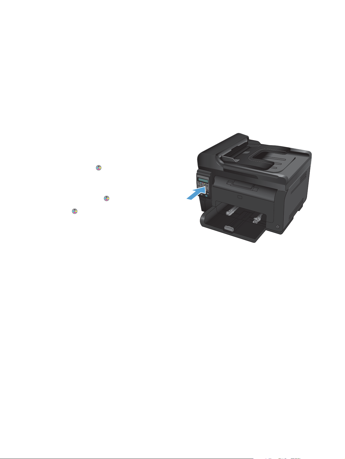
1. Some error messages or status messages cause
the product to rotate the print cartridge
carousel to the affected cartridge
automatically. If the print cartridge that needs
to be replaced is not in the correct position,
press the Cartridge
cartridge carousel to the cartridge color that
you want to replace.
NOTE: All doors must be closed when
pressing the Cartridge
imaging drum must be installed for the
Cartridge
NOTE: Wait until the Rotating message
and the rotation sounds stop before opening
the print cartridge door.
button to work.
button to rotate the print
button. Also, the
ENWW
Removal and replacement procedures
7
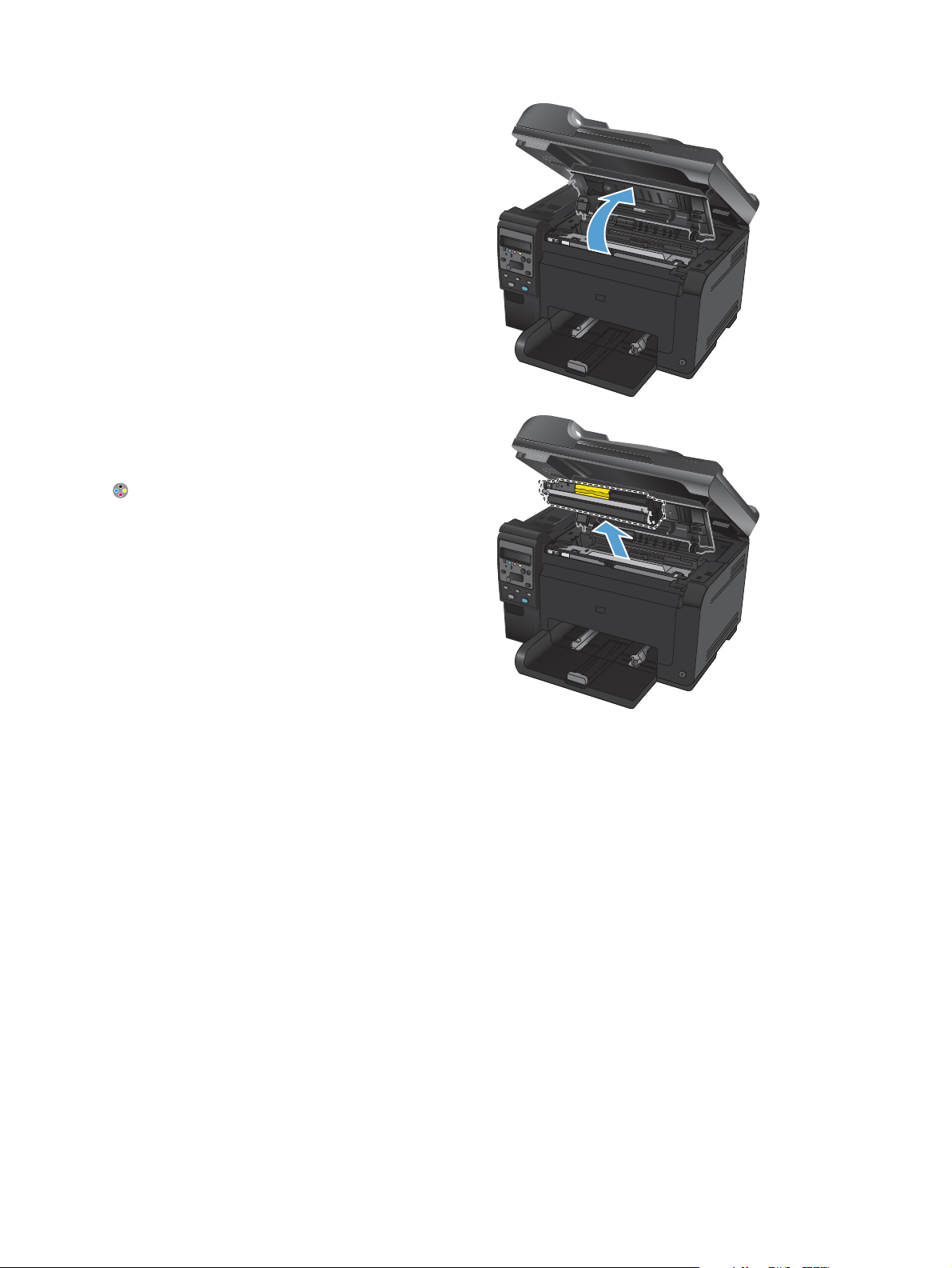
2. Open the print cartridge door.
3. Grasp the old print cartridge by the center
handle and remove it.
Close the doors, and then press the Cartridge
button to rotate the print cartridge carousel
to the next cartridge. Repeat to remove all
cartridges.
NOTE: Make sure that you store the
removed print cartridges away from strong
light. HP recommends that you cover the print
cartridges while servicing the product.
8 Chapter 1 Removal and replacement ENWW
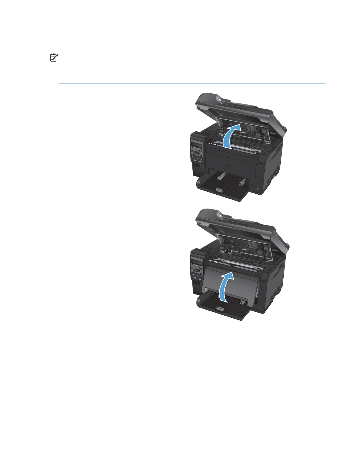
Imaging drum
NOTE: The imaging drum installed in this product is covered by the product warranty. Replacement
imaging drums have a one-year limited warranty from the date of installation. The imaging drum
installation date displays on the supplies status page. The HP Premium Protection Warranty applies only
to the print cartridges for the product.
1. Open the print cartridge door.
2. Open the front cover.
ENWW
Removal and replacement procedures
9
3. Lift the two levers that hold the imaging drum.
4. Remove the old imaging drum.
NOTE: Make sure that you store the
removed imaging drum away from strong
light. HP recommends that you cover the
imaging drum while servicing the product.
10 Chapter 1 Removal and replacement ENWW
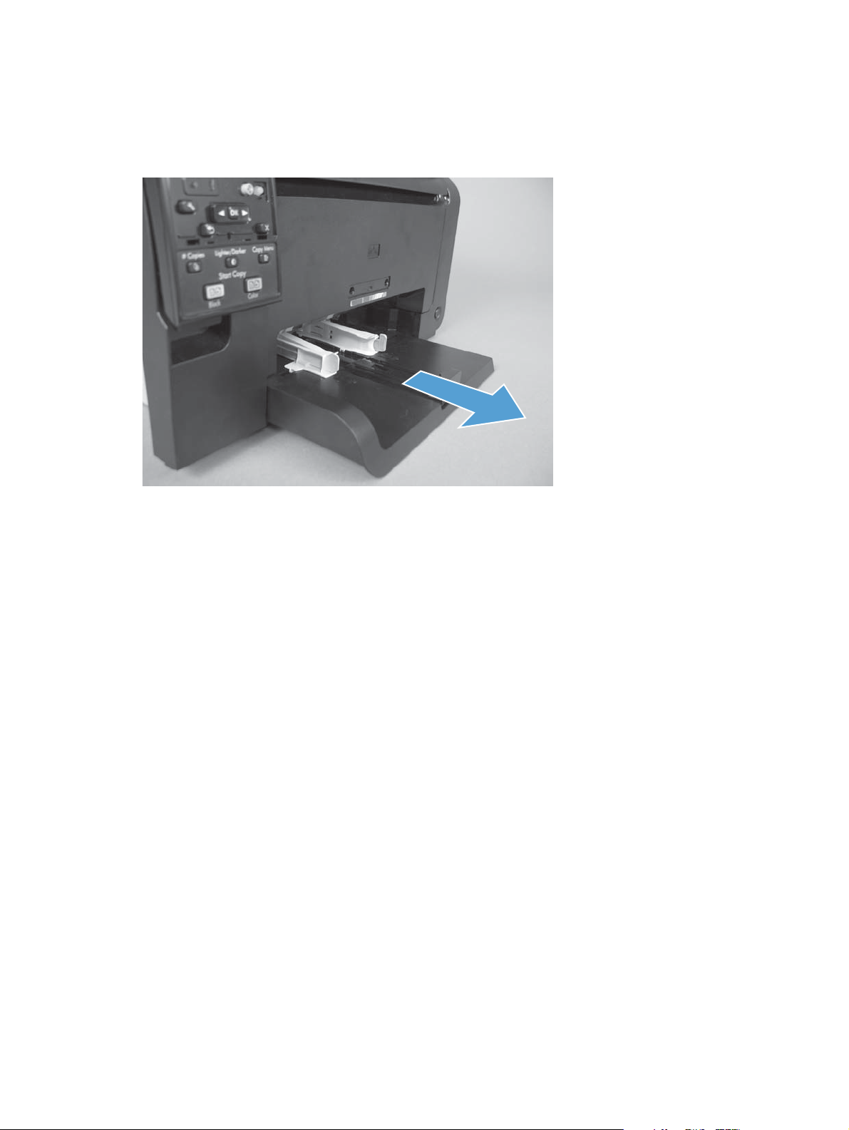
Input tray
Pull the tray away from the printer to remove.
Figure 1-4 Remove the tray
ENWW
Removal and replacement procedures
11
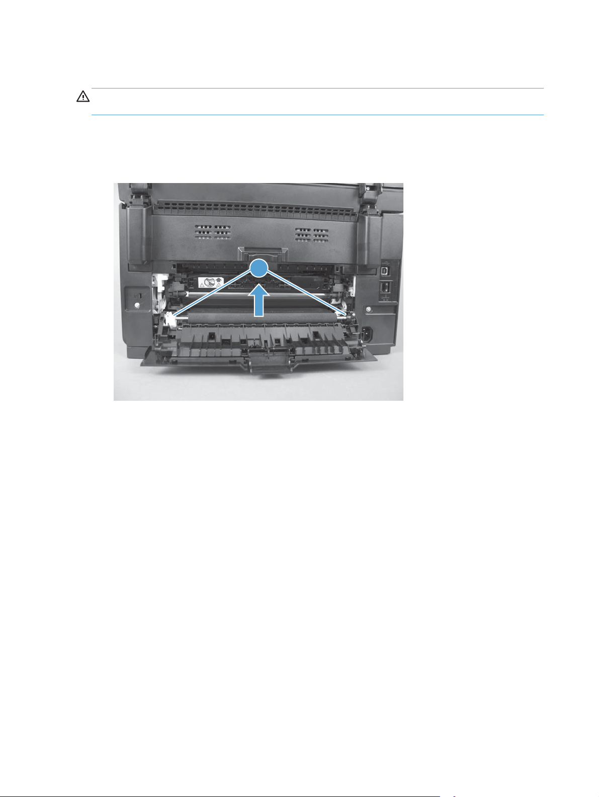
Secondary transfer roller
CAUTION: Do not touch the black spongy part of the roller. Skin oils might cause print-quality
problems.
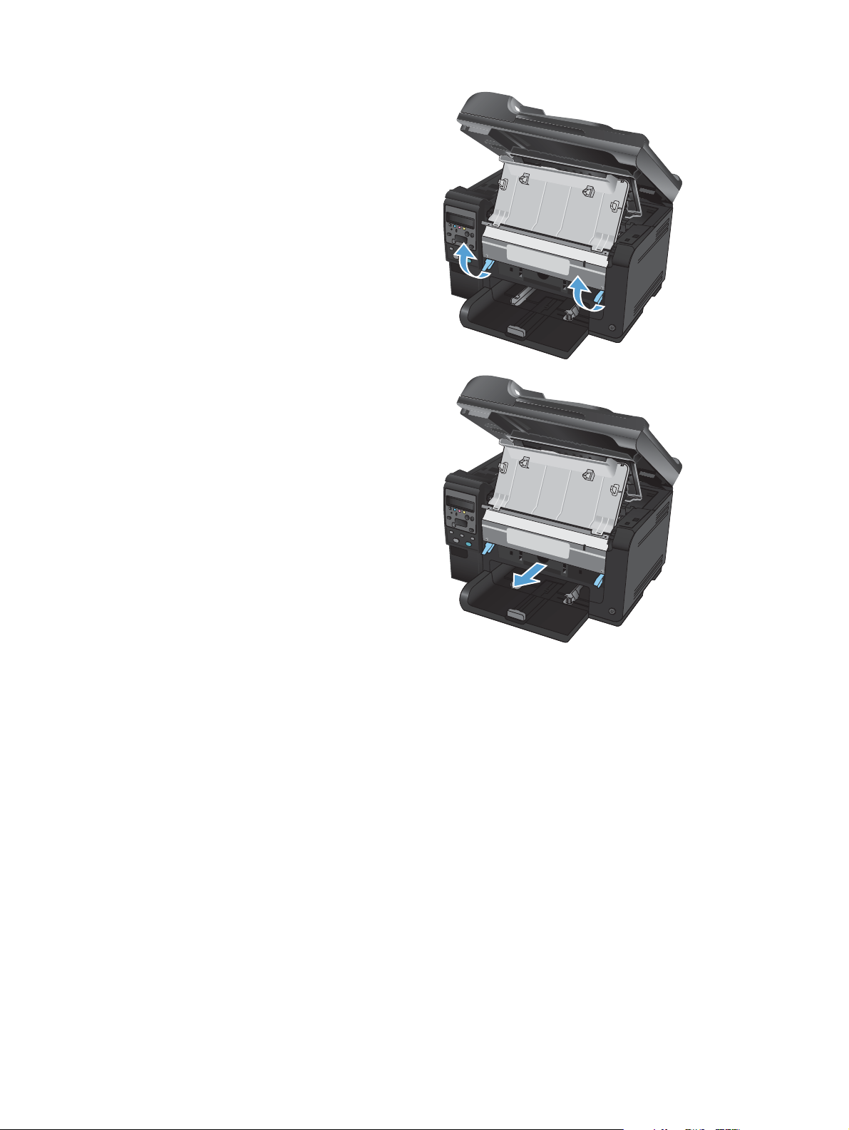
1. Open the rear door.
2. Release two clips (callout 1), and then remove the roller from the product.
Figure 1-5 Remove the secondary transfer roller
1
12 Chapter 1 Removal and replacement ENWW
Loading…
На этой странице вы можете совершенно бесплатно скачать Инструкция по эксплуатации HP LaserJet Pro 100 color MFP M175a.
У документа PDF Инструкция по эксплуатации 220 страниц, а его размер составляет 4.39 Mb.
Читать онлайн МФУ HP LaserJet Pro 100 color MFP M175a Инструкция по эксплуатации
Скачать файл PDF «HP LaserJet Pro 100 color MFP M175a Инструкция по эксплуатации» (4.39 Mb)
Популярность:
4129 просмотры
Подсчет страниц:
220 страницы
Тип файла:
Размер файла:
4.39 Mb
Прочие инструкции HP LaserJet Pro 100 color MFP M175a
Прочие инструкции HP МФУ
Прочие инструкции HP
Software Technical Reference
236 pages
en
User Guide
220 pages
en
Installation Guide
16 pages
ar
cs
de
en
fi
fr
it
nn
sv
tr
dk
sp
nl
pt
Quick Reference Guide
18 pages
en
LASERJET PRO 100 COLOR MFP M175
Software Technical Reference
LaserJet Pro 100 Color MFP M175
Software Technical Reference
Copyright and License
2011 Copyright Hewlett-Packard Development Company, L.P.
Reproduction, adaptation, or translation without prior written permission is prohibited, except as allowed under the copyright laws.
The information contained herein is subject to change without notice.
The only warranties for HP products and services are set forth in the express warranty statements accompanying such products and services. Nothing herein should be construed as constituting an additional warranty. HP shall not be liable for technical or editorial errors or omissions contained herein.
Edition 1, 4/2011
Trademark Credits
Adobe, Acrobat, and PostScript are trademarks of Adobe Systems Incorporated.
Intel Core is a trademark of Intel Corporation in the U.S. and other countries.
Microsoft, Windows, Windows XP, and Windows Vista are U.S. registered trademarks of Microsoft Corporation.
UNIX is a registered trademark of The Open Group.
PANTONE is Pantone, Inc’s check- standard trademark for color.
Table of contents
1 Document and product basics ………………………………………………………………………………. 1
Purpose and scope ……………………………………………………………………………………………………. 2 Documentation availability and localization …………………………………………………………………….. 3
User documentation ……………………………………………………………………………………… 4 User guide …………………………………………………………………………………… 4 Readme ………………………………………………………………………………………. 4 Help & Learn Center ……………………………………………………………………….. 5
Software availability and localization …………………………………………………………………………….. 6 Printing-system software on the Web ………………………………………………………………… 6
In-box printing-system software CD ……………………………………………………… 6 HP LaserJet Windows software CD ………………………………………… 6 CD versions and language support ………………………………………… 8
2 Windows software description …………………………………………………………………………… 13
Introduction …………………………………………………………………………………………………………… 13 Windows printing-system software ………………………………………………………………………………. 14
Windows printing-system software …………………………………………………………………. 14 HP Color LaserJet printer drivers …………………………………………………………………….. 16
HP PCL 6 Print Driver, PCL 5 Universal Print Driver, and PS Universal Print Driver ……………………………………………………………………………………….. 16 Printer-driver version numbers for Windows operating systems ………………….. 16
Driver configuration for Windows ……………………………………………………………………………….. 18 Driver autoconfiguration ……………………………………………………………………………… 18 Bidirectional communication …………………………………………………………………………. 18 Enterprise AutoConfiguration ………………………………………………………………………… 18 Update Now ……………………………………………………………………………………………. 20 HP Driver Configuration ………………………………………………………………………………. 21
Continuous export ………………………………………………………………………… 23 Advanced color use ………………………………………………………………………………………………… 24
Color use monitoring ………………………………………………………………………………….. 24 PANTONE color profiles ……………………………………………………………………………… 24
HP Device Toolbox ………………………………………………………………………………………………….. 26
ENWW iii
Status tab ………………………………………………………………………………………………… 27 Device Status ………………………………………………………………………………. 27 Supplies Status …………………………………………………………………………….. 28 Device Configuration page ……………………………………………………………… 29 Network Summary page ………………………………………………………………… 30 Reports ……………………………………………………………………………………… 30 Color Usage Log ………………………………………………………………………….. 31 Event Log page ……………………………………………………………………………. 32
System tab ………………………………………………………………………………………………. 32 Device Information page ………………………………………………………………… 32 Paper Setup page ………………………………………………………………………… 33 Print Quality page ………………………………………………………………………… 33 Energy Settings page …………………………………………………………………….. 34 Print Density page ………………………………………………………………………… 35 Paper Types page ………………………………………………………………………… 36 System Setup page ……………………………………………………………………….. 36 Service page ………………………………………………………………………………. 37 Product Security page ……………………………………………………………………. 37
Print tab ………………………………………………………………………………………………….. 37 Printing ……………………………………………………………………………………… 38 PCL5 ………………………………………………………………………………………… 38 PostScript …………………………………………………………………………………… 38
Networking tab ………………………………………………………………………………………… 39 Network Summary ……………………………………………………………………….. 40 IPv4 Configuration ……………………………………………………………………….. 40 IPv6 Configuration ……………………………………………………………………….. 41 Wireless Configuration ………………………………………………………………….. 43 Network Identification ……………………………………………………………………. 43 Advanced page …………………………………………………………………………… 45 SNMP page ……………………………………………………………………………….. 45
HP Web Services tab …………………………………………………………………………………. 46 Web Services Setup page ………………………………………………………………. 46 Proxy Settings page ………………………………………………………………………. 46
HP Smart Install tab ……………………………………………………………………………………. 47 HP Web Jetadmin …………………………………………………………………………………………………… 48 HP Customer Participation Program ……………………………………………………………………………… 49 Scan software ………………………………………………………………………………………………………… 50
HP Scan software ………………………………………………………………………………………. 50 E-mail ……………………………………………………………………………………….. 53 Scan settings ………………………………………………………………………………. 53
Scan drivers …………………………………………………………………………………………….. 54
iv ENWW
WIA driver …………………………………………………………………………………. 54 Font support ………………………………………………………………………………………………………….. 56
Basic fonts ……………………………………………………………………………………………….. 56 Default fonts …………………………………………………………………………………………….. 56
HP Driver Deployment Utility ………………………………………………………………………………………. 62
3 Install Windows printing-system components ……………………………………………………….. 71
Supported operating systems for Windows …………………………………………………………………….. 72 Install overview ………………………………………………………………………………………………………. 73
Software installation types for Windows ………………………………………………………….. 73 Installation options …………………………………………………………………………………….. 73
General Windows installation instructions ……………………………………………………………………… 74 General Windows HP Smart Install installation instructions ……………………………………. 74 General Windows installation from the software CD-ROM for direct connections ………… 74
Windows installation instructions for direct-connected (USB) products …………. 74 Printer-driver only installation instructions (Microsoft Add Printer Wizard) …….. 75
General Windows installation from the software CD-ROM for network connections ……… 76 Printer sharing disclaimer ……………………………………………………………….. 76 Network setup …………………………………………………………………………….. 77 Windows installation instructions for network-connected products ………………. 77 Printer-driver only installation instructions (Microsoft Add Printer Wizard) …….. 78
Point-and-Print installation for Windows …………………………………………………………… 78 Modify a pre-existing installation ……………………………………………………………………. 79
Detailed Windows installation instructions ……………………………………………………………………… 81 Use HP Smart Install to install the product software ……………………………………………… 81 Use the installation CD to install the product software ………………………………………….. 89
Install optional software ……………………………………………………………………………………………. 98 Uninstall software ………………………………………………………………………………………………….. 102
Use the HP Uninstall utility to remove the product software ………………………………….. 102 Use the software CD to remove the product software …………………………………………. 104 Remove the printer driver by using the Windows Add or Remove Programs feature ……. 107 Uninstall the printer driver by using the Server Properties feature …………………………… 109
4 HP PCL 6 printer driver and HP PS Universal Print Driver for Windows …………………….. 111
Introduction …………………………………………………………………………………………………………. 111 Access printer drivers …………………………………………………………………………………………….. 112
Printing Preferences driver tabs ……………………………………………………………………. 112 Properties driver tabs ………………………………………………………………………………… 113
Help system …………………………………………………………………………………………………………. 114 What’s this? Help ………………………………………………………………………………….. 114 Incompatible print settings messages …………………………………………………………….. 114
ENWW v
Advanced tab features ……………………………………………………………………………………………. 117 Graphic ………………………………………………………………………………………………… 118
Image Color Management ……………………………………………………………. 118 True Type Font …………………………………………………………………………… 118
Document Options …………………………………………………………………………………… 118 Advanced Printing Features …………………………………………………………… 118 Printer Features ………………………………………………………………………….. 119 Layout Options ………………………………………………………………………….. 119
Printing Shortcuts tab features …………………………………………………………………………………… 121 Use defined printing shortcuts ……………………………………………………………………… 122
General Everyday Printing …………………………………………………………….. 122 Paper type …………………………………………………………………… 122 Paper sizes ………………………………………………………………….. 124 Paper source ……………………………………………………………….. 124 Print on both sides …………………………………………………………. 125 Color options ……………………………………………………………….. 125 Pages per sheet …………………………………………………………….. 125
Eco-print (Two-sided Printing) …………………………………………………………. 125 Factory Defaults …………………………………………………………………………. 125 Envelopes …………………………………………………………………………………. 126 Cardstock Heavy ……………………………………………………………………….. 126 Glossy/Presentation ……………………………………………………………………. 126
Snapshot Photos ………………………………………………………………………………………. 126 Labels …………………………………………………………………………………………………… 127 Transparencies ……………………………………………………………………………………….. 127 Create a custom printing shortcut …………………………………………………………………. 127
Paper/Quality tab features ………………………………………………………………………………………. 128 Paper Options ………………………………………………………………………………………… 128
Paper sizes ……………………………………………………………………………….. 129 Custom Paper Size ……………………………………………………………………… 129
Name ………………………………………………………………………… 129 Paper size …………………………………………………………………… 130 Units ………………………………………………………………………….. 130 Custom width and height control limits ………………………………… 130
Paper source …………………………………………………………………………….. 130 Paper type ……………………………………………………………………………….. 131 Special pages ……………………………………………………………………………. 133
Covers ……………………………………………………………………….. 133 Print pages on different paper …………………………………………… 133
Document preview image …………………………………………………………………………… 134 Print Quality …………………………………………………………………………………………… 134
vi ENWW
Print Quality drop-down menu ……………………………………………………….. 134 Effects tab features ………………………………………………………………………………………………… 135
Resizing Options ……………………………………………………………………………………… 136 Actual Size ……………………………………………………………………………….. 136 Print Document On ……………………………………………………………………… 136 Scale to Fit ……………………………………………………………………………….. 136 % of Actual Size ………………………………………………………………………… 136
Document preview image …………………………………………………………………………… 137 Watermarks …………………………………………………………………………………………… 137
Current watermarks …………………………………………………………………….. 138 Watermark Message …………………………………………………………………… 139 Message Angle ………………………………………………………………………….. 139 Font Attributes ……………………………………………………………………………. 139 Default watermark settings …………………………………………………………….. 140
Finishing tab features ……………………………………………………………………………………………… 142 Document Options …………………………………………………………………………………… 142
Print on Both Sides (manually) ………………………………………………………… 143 Print on both sides manually …………………………………………….. 143
Flip Pages Up ……………………………………………………………………………. 145 Booklet Layout …………………………………………………………………………… 145
Book and Booklet Printing ……………………………………………….. 145 Pages per Sheet …………………………………………………………………………. 146 Print Page Borders ………………………………………………………………………. 147 Page Order ………………………………………………………………………………. 147
Document preview image …………………………………………………………………………… 147 Orientation …………………………………………………………………………………………….. 147
Color tab features …………………………………………………………………………………………………. 149 Color Options …………………………………………………………………………………………. 150
Automatic …………………………………………………………………………………. 150 Manual ……………………………………………………………………………………. 150 Neutral Grays ……………………………………………………………………………. 151
Color Themes …………………………………………………………………………………………. 151 Default (sRGB) …………………………………………………………………………… 151 Photo (sRGB) …………………………………………………………………………….. 151 Photo (Adobe RGB 1998) …………………………………………………………….. 151 Vivid (sRGB) ……………………………………………………………………………… 152 None ………………………………………………………………………………………. 152
Document preview image …………………………………………………………………………… 152 HP EasyColor …………………………………………………………………………………………. 152
Services tab features ………………………………………………………………………………………………. 153 Internet Services ………………………………………………………………………………………. 153
ENWW vii
Device Settings tab features ……………………………………………………………………………………… 155 Form to Tray Assignment ……………………………………………………………………………. 155 Font Substitution Table ………………………………………………………………………………. 156
External Fonts ……………………………………………………………………………. 156 Installing external fonts ……………………………………………………. 156 Removing external fonts ………………………………………………….. 157
Installable Options …………………………………………………………………………………… 157 Allow Manual Duplexing ………………………………………………………………. 157 Job Separator ……………………………………………………………………………. 158 Printer Status Notifications …………………………………………………………….. 158
About tab features …………………………………………………………………………………………………. 159
5 Mac software and utilities ……………………………………………………………………………….. 161
Supported operating systems for Mac …………………………………………………………………………. 162 Mac system requirements ………………………………………………………………………………………… 162
Hardware requirements …………………………………………………………………………….. 162 Change printer-driver settings for Mac ………………………………………………………………………… 162 Mac printing-system software ……………………………………………………………………………………. 163
HP LaserJet Pro 100 Color MFP M175 PPD …………………………………………………….. 163 HP LaserJet Pro 100 Color MFP M175 PDE …………………………………………………….. 163 HP USB EWS Gateway ……………………………………………………………………………… 163 HP Utility ……………………………………………………………………………………………….. 164 Supported printer drivers for Mac ………………………………………………………………… 164 Priority for print settings for Mac ………………………………………………………………….. 164
Install the Mac printing-system software ……………………………………………………………………….. 165 General installation for Mac operating systems ………………………………………………… 165 Detailed Mac installation for a USB connection ………………………………………………… 165 Detailed Mac installation for a network connection ……………………………………………. 174 Setup instructions …………………………………………………………………………………….. 182
Set up a printer with a Mac …………………………………………………………… 182 Troubleshoot the product setup ……………………………………………………….. 183
Remove the printing-system software from Mac operating systems ………………………………………. 184 Supported utilities for Mac ………………………………………………………………………………………. 188
HP Utility for Mac …………………………………………………………………………………….. 188 Open the HP Utility ……………………………………………………………………… 188 HP Utility toolbar ………………………………………………………………………… 189 Supplies Status …………………………………………………………………………… 190 Device Information ……………………………………………………………………… 190 Color Usage ……………………………………………………………………………… 191 File Upload ………………………………………………………………………………. 191 Upload Fonts …………………………………………………………………………….. 192
viii ENWW
Trays Configuration …………………………………………………………………….. 193 Network Settings ………………………………………………………………………… 193 Additional Settings ……………………………………………………………………… 195 Message Center …………………………………………………………………………. 195
HP Embedded Web Server (EWS) ………………………………………………………………… 196
6 Engineering details …………………………………………………………………………………………. 197
Introduction …………………………………………………………………………………………………………. 197 Printing print-ready documents ………………………………………………………………………………….. 198
Print-ready file printing by using FTP through a browser ……………………………………… 198 Print-ready file printing by using FTP on a direct network connection ………………………. 199
Windows operating systems ………………………………………………………….. 199 Mac OS X operating systems …………………………………………………………. 200
Print-ready printing by using a local Windows port …………………………………………… 200 Windows 2000 Service Pack 3, Windows XP, Windows Server 2003, Windows Server 2008, Windows Vista, or Windows 7 ……………………….. 201
Print-ready file printing in a Windows network …………………………………………………. 201 Print-ready file printing in UNIX systems …………………………………………………………. 201 Print-ready file printing by using the LPR command ……………………………………………. 201
Tools for troubleshooting …………………………………………………………………………………………. 203 Control panel messages …………………………………………………………………………….. 203
10.100X Supply memory error ………………………………………………………. 203 49 Error …………………………………………………………………………………… 203 50.X Fuser Error …………………………………………………………………………. 203 52 Scanner Error ……………………………………………………………………….. 203 79 Error …………………………………………………………………………………… 204 Document Feeder Jam ………………………………………………………………….. 204 Document Feeder Mispick. Reload. ………………………………………………….. 204 Door open ………………………………………………………………………………… 204 55.4 error. Turn off then turn on. …………………………………………………….. 204 Engine Error. Press [OK]. ……………………………………………………………… 205 Jam in Area. Open Door and Clear Jam. ………………………………………….. 205 Jam in Tray 1. Clear Jam and then Press [OK]. …………………………………… 205 Load Paper ……………………………………………………………………………….. 205 Print Failure. Press [OK]. ………………………………………………………………. 205 Scanner Error
. Turn off and then on. ………………………………………… 206 Scanning Error. Cannot Connect. ……………………………………………………. 206
Event log messages ………………………………………………………………………………….. 206 Show an event log ……………………………………………………………………… 206
Engine diagnostics …………………………………………………………………………………… 208 Engine test ……………………………………………………………………………….. 209
ENWW ix
Index ………………………………………………………………………………………………………………. 211
x ENWW
List of tables
Table 1-1Documentation availability ………………………………………………………………………………………… 3 Table 1-2Software CD supported languages ………………………………………………………………………………. 8 Table 1-3Supported printer driver languages …………………………………………………………………………….. 10 Table 1-4Installer component languages ………………………………………………………………………………….. 11 Table 1-5Documentation languages ……………………………………………………………………………………….. 12 Table 2-1Software components for Windows ……………………………………………………………………………. 14 Table 2-2Automatic discovery and driver configuration through bidirectional communication1 ………………… 18 Table 2-3EAC availability in Microsoft Windows and Microsoft Share …………………………………………….. 19 Table 2-4EAC availability in Novell Netware environments …………………………………………………………… 20 Table 2-5Operating systems that support HP Driver Preconfiguration ……………………………………………….. 23 Table 2-6Color access monitoring tools …………………………………………………………………………………… 24 Table 2-7Network Identification pane Text Entities ……………………………………………………………………. 44 Table 2-8Examples of supported e-mail programs ………………………………………………………………………. 53 Table 2-9Available scan settings ……………………………………………………………………………………………. 53 Table 2-10Default fonts ………………………………………………………………………………………………………. 56 Table 2-11Additional PS emulation fonts ………………………………………………………………………………….. 59 Table 4-1Font Attribute settings for new and preset watermarks ……………………………………………………. 140 Table 4-2Page orientation ………………………………………………………………………………………………….. 145 Table 6-1Event-log messages ………………………………………………………………………………………………. 207
ENWW xi
List of figures
Figure 1-1Installation software CD Documentation screen …………………………………………………………….. 4 Figure 1-2Help & Learn Center ……………………………………………………………………………………………….. 5 Figure 2-1IP address location on the configuration page ………………………………………………………………. 26 Figure 2-2HP Device Toolbox, Status tab Device Status page ………………………………………………………. 27 Figure 2-3HP Device Toolbox, Status tab Supplies Status page ……………………………………………………. 28 Figure 2-4HP Device Toolbox, Status tab Device Configuration page …………………………………………….. 29 Figure 2-5HP Device Toolbox, Status tab Network Summary page ……………………………………………….. 30 Figure 2-6HP Device Toolbox, Status tab Reports page ……………………………………………………………… 31 Figure 2-7HP Device Toolbox, Status tab Color Usage Log page ………………………………………………….. 31 Figure 2-8HP Device Toolbox, Status tab Event Log page …………………………………………………………… 32 Figure 2-9HP Device Toolbox, System tab Device Information page ………………………………………………. 33 Figure 2-10HP Device Toolbox, System tab Paper Handling page ………………………………………………… 33 Figure 2-11HP Device Toolbox, System tab Print Quality page …………………………………………………….. 33 Figure 2-12HP Device Toolbox, System tab Energy Settings page ………………………………………………… 34 Figure 2-13HP Device Toolbox, System tab Print Density page …………………………………………………….. 35 Figure 2-14HP Device Toolbox, System tab Paper Types page …………………………………………………….. 36 Figure 2-15HP Device Toolbox, System tab System Setup page …………………………………………………… 36 Figure 2-16HP Device Toolbox, System tab Service page …………………………………………………………… 37 Figure 2-17HP Device Toolbox, System tab Product Security page ………………………………………………… 37 Figure 2-18HP Device Toolbox, Print tab Printing page ……………………………………………………………… 38 Figure 2-19HP Device Toolbox, Print tab PCL5 page ………………………………………………………………… 38 Figure 2-20HP Device Toolbox, Print tab PostScript page …………………………………………………………… 39 Figure 2-21HP Device Toolbox, Networking tab Network Summary page ………………………………………. 40 Figure 2-22HP Device Toolbox, Networking tab IPv4 Configuration page ………………………………………. 41 Figure 2-23HP Device Toolbox, Networking tab IPv6 Configuration page ………………………………………. 42 Figure 2-24HP Device Toolbox, Networking tab Wireless Configuration page …………………………………. 43 Figure 2-25HP Device Toolbox, Networking tab Network Identification page ………………………………….. 44 Figure 2-26HP Device Toolbox, Networking tab Advanced page …………………………………………………. 45 Figure 2-27HP Device Toolbox, Networking tab SNMP page ……………………………………………………… 45 Figure 2-28HP Device Toolbox, Web Services Setup page …………………………………………………………… 46 Figure 2-29HP Device Toolbox, Proxy Settings page …………………………………………………………………… 46 Figure 2-30HP Device Toolbox, HP Smart Install tab ……………………………………………………………………. 47
ENWW xiii
Figure 2-31Welcome screen ………………………………………………………………………………………………… 49 Figure 2-32HP Scan dialog box …………………………………………………………………………………………….. 51 Figure 2-33Advanced Settings dialog box ……………………………………………………………………………….. 52 Figure 2-34WIA-driver user interface flatbed …………………………………………………………………………. 55 Figure 2-35Package Source …………………………………………………………………………………………………. 64 Figure 2-36Network Settings ………………………………………………………………………………………………… 65 Figure 2-37HP DDU Driver Configuration settings ………………………………………………………………………. 67 Figure 3-1Installer screen Welcome Back screen …………………………………………………………………….. 79 Figure 3-2HP Smart Install License agreement screen ……………………………………………………………….. 81 Figure 3-3HP Smart Install Software Install screen …………………………………………………………………… 82 Figure 3-4Software installation Connection Type screen …………………………………………………………… 82 Figure 3-5Software installation Connect the Product screen ……………………………………………………….. 83 Figure 3-6Software installation Connection Type screen for wired network installation ………………………. 84 Figure 3-7Software installation Network Product(s) Found screen ………………………………………………… 85 Figure 3-8Software installation Connection Type screen for wireless connected installation ………………… 85 Figure 3-9Software installation Connect USB screen for wireless connected installation …………………….. 86 Figure 3-10Software installation Wireless Network(s) Found screen for wireless connected installation ….. 87 Figure 3-11Software installation Wireless Network Setup screen for wireless connected installation ……… 88 Figure 3-12Software installation Complete screen …………………………………………………………………… 88 Figure 3-13Software installation More Options screen …………………………………………………………….. 89 Figure 3-14Software installation License agreement screen ……………………………………………………….. 90 Figure 3-15Software installation Connection Type screen …………………………………………………………. 91 Figure 3-16Software installation Connect the Product screen ……………………………………………………… 91 Figure 3-17Software installation Connection Type screen for network connected installation ………………. 92 Figure 3-18Software installation Network Product(s) Found screen ………………………………………………. 93 Figure 3-19Software installation Connection Type screen for wireless connected installation ………………. 93 Figure 3-20Software installation Connect USB screen for wireless connected installation …………………… 94 Figure 3-21Software installation Wireless Network(s) Found screen for wireless connected installation ….. 95 Figure 3-22Software installation Wireless Network Setup screen for wireless connected installation ……… 96 Figure 3-23Software installation Complete screen …………………………………………………………………… 96 Figure 3-24Software installation More Options screen …………………………………………………………….. 97 Figure 3-25Software installation Welcome Back screen ……………………………………………………………. 98 Figure 3-26Software installation More Options screen …………………………………………………………….. 99 Figure 3-27Software installation Documentation screen ……………………………………………………………. 99 Figure 3-28Software installation Admin Software screen ………………………………………………………… 100 Figure 3-29Software installation Get Specialized Drivers screen ……………………………………………….. 100 Figure 3-30Software installation Web Support screen ……………………………………………………………. 101 Figure 3-31HP Uninstaller utility Uninstall button …………………………………………………………………… 102 Figure 3-32HP Uninstaller utility Reboot Now button ……………………………………………………………… 103 Figure 3-33HP Uninstaller utility Reboot Later button ………………………………………………………………. 103 Figure 3-34Software installation Welcome Back screen ………………………………………………………….. 104
xiv ENWW
Figure 3-35Software installation Uninstall option selected ……………………………………………………….. 105 Figure 3-36Software uninstall Uninstall button ……………………………………………………………………… 105 Figure 3-37Software uninstall Reboot Now button ………………………………………………………………… 106 Figure 3-38Software uninstall Reboot Later button …………………………………………………………………. 106 Figure 3-39Windows Control Panel screen …………………………………………………………………………….. 107 Figure 3-40HP Driver Uninstall Utility screen ……………………………………………………………………………. 108 Figure 3-41HP Driver Uninstall Complete screen ………………………………………………………………………. 108 Figure 4-1Incompatible print settings warning ………………………………………………………………………….. 115 Figure 4-2Incompatible Print Settings dialog ……………………………………………………………………………. 115 Figure 4-3Advanced tab ……………………………………………………………………………………………………. 117 Figure 4-4Printing Shortcuts tab …………………………………………………………………………………………… 121 Figure 4-5Paper/Quality tab ………………………………………………………………………………………………. 128 Figure 4-6Effects tab ………………………………………………………………………………………………………… 135 Figure 4-7Finishing tab ……………………………………………………………………………………………………… 142 Figure 4-8Print on Both Sides Instructions dialog box …………………………………………………………………. 144 Figure 4-9Color tab …………………………………………………………………………………………………………. 149 Figure 4-10Services tab …………………………………………………………………………………………………….. 153 Figure 4-11Device Settings tab ……………………………………………………………………………………………. 155 Figure 4-12About tab ……………………………………………………………………………………………………….. 159 Figure 5-1Mac USB installation Overview screen ………………………………………………………………….. 166 Figure 5-2Mac USB installation License screen …………………………………………………………………….. 167 Figure 5-3Mac USB installation License pop-up …………………………………………………………………….. 167 Figure 5-4Mac USB installation HP ePrint Offer scree