
AVR 235 Audio/ VideoReceiver
OWNER’S MANUAL
Power for the Digital Revolution
®
2 TABLE OF CONTENTS
3 Introduction
4 Safety Information
4 Unpacking
5 Front Panel Controls
7 Rear Panel Connections
9 Main Remote Control Functions
12 Installation and Connections
12 Audio Connections
12 External Amplifier Connections
13 Video Connections
13 SCART A/V Connections
14 System and Power Connections
15 Speaker Selection
15 Speaker Placement
16 System Configuration
16 First Turn On
16 Using the On-Screen Display
16 System Setup
17 Input Setup
17 Speaker Setup
20 Surround Setup
21 Night Mode Settings
21 Configuring the Surround Off
(Stereo) Modes
22 Delay Settings
23 Output Level Adjustment
23 Using EzSet
24 Manual Output Level Adjustment
26 Operation
26 Surround Mode Chart
28 Basic Operation
28 Source Selection
28 6/8-Channel Direct Input
29 Controls and Use of Headphones
29 Surround Mode Selection
30 Digital Audio Playback
30 Dolby Digital
30 DTS
30 PCM Audio Playback
30 Selecting a Digital Source
30 Digital Bitstream Indicators
31 Surround mode Types
31 PCM Playback Indications
31 Speaker/Channel Indicators
32 Night Mode
32 Tape Recording
32 Output Level Adjustment
With Source Signals
33 Memory backup
33 Advanced Features
33 Front Panel Display Fade
34 Display Brightness
34 Turn-On Volume Level
34 Semi-OSD Settings
34 Full-OSD Time Out Adjustment
35 Default Surround Mode
35 Tuner Operation
35 Basic Tuner Operation
35 Station Selection
35 Preset Tuning
36 RDS Operation
36 RDS Tuning
36 RDS Display Options
36 Program Search
37 Programming the Remote
37 Programming the Remote with Codes
37 Direct Code Entry
Table of Contents
Typographical Conventions
In order to help you use this manual with the remote control, front-panel controls and rear-panel
connections, certain conventions have been used.
EXAMPLE – (bold type) indicates a specific remote control or front-panel button, or rear-panel
connection jack
EXAMPLE – (OCR type) indicates a message that is visible on the front-panel information display
1
– (number in a square) indicates a specific front-panel control
– (number in a circle) indicates a rear-panel connection
0
– (number in an oval) indicates a button or indicator on the remote
The appearance of the text or cursor for your receiver’s on-screen menus may vary slightly from the
illustrations in this manual. Whether the text appears in all uppercase or upper- and lowercase
characters, performance and operation remain the same.
Declaration of Conformity
We, Harman Consumer Group International
2, route de Tours
72500 Château-du-Loir,
FRANCE
declare in own responsibility, that the product
described in this owner’s manual is in compliance
with technical standards:
EN 55013:2001 + A1:2003
EN 55020:2002 + A1:2003
EN 61000-3-2:2000
EN 61000-3-3:1995 + A1:2001
EN 60065:2002
Jurjen Amsterdam
Harman Consumer Group International
01/05
37 Auto Search Method
37 Code Readout
38 Macro Programming
38 Programmed Device Functions
38 Volume Punch-Through
39 Channel Control Punch-Through
39 Transport Control Punch-Through
39 Reassigning Device Control Selectors
39 Resetting the Remote Memory
40 Function List
42 Troubleshooting Guide
42 Processor Reset
43 Technical Specifications

INTRODUCTION 3
Introduction
Thank you for choosing Harman Kardon!
With the purchase of a Harman Kardon
AVR 235 you are about to begin many years of
listening enjoyment. Designed to provide all the
excitement and detail of movie soundtracks and
every nuance of musical selections, the AVR 235
is truly a multichannel receiver for the new millennium. In addition to the traditional 5.1 digital
decoding modes such as Dolby Digital and DTS,
it offers the latest advancements in surround
technology such as Dolby Pro Logic II and IIx, the
full suite of DTS-ES 6.1 modes, DTS Neo:6 and
the latest 7.1 channel versions of Harman’s own
Logic 7 technology.
The AVR 235 has been engineered so that it is
easy to take advantage of all the power of its
digital technology. On-screen menus, fully color
coded connection jacks and terminals and our
exclusive EzSet
™
remote make installation fast
and simple. However, to obtain the maximum
enjoyment from your new receiver, we urge you
to read this manual. A few minutes spent learning the functions of the various controls will
enable you to take advantage of all the power
the AVR 235 is able to deliver.
If you have any questions about this product, its
installation or its operation, please contact your
retailer or custom installer. They are your best
local sources of information.
Description and Features
The AVR 235 is among the most versatile and
multifeatured A/V receivers available, incorporating a wide range of listening options. In addition
to Dolby Digital and DTS decoding for digital
sources, a broad choice of surround modes for
Matrix surround-encoded or Stereo recordings
are available for use with sources such as CD,
VCR, TV broadcasts and the AVR’s own FM/AM
tuner. Along with Dolby Digital EX, Dolby Pro
Logic II and IIx, DTS Neo:6, Dolby 3 Stereo, 5
Channel or 7 Channel Stereo and Hall and
Theater modes, the AVR offers Harman
International’s exclusive Logic 7 process in both
5.1 and 7.1 versions to create a wider, more
enveloping field environment and more defined
fly-overs and pans.Although the AVR 235’s
primary use will be in multichannel systems,
advanced technology is at work even when only
two speakers are used. Dolby Virtual Speaker
and Harman International’s proprietary VMAx
®
are both available to create enveloping sound
fields from front left and right speakers, and the
latest Dolby Headphone circuitry creates an
amazing sense of openness with headphones.
In addition to providing a wide range of listening
options, the AVR is easy to configure so that it
provides the best results with your speakers and
specific listening-room environment.
A Stereo-Direct mode bypasses the digital
processor to preserve all of the subtleties of
older analog, two-channel materials, while bass
management, available in the surround and
Stereo-Digital modes,improves your ability to
tailor the sound to suit your room acoustics or
taste.
On-screen menus make it simple to enter settings for speaker configurations and bass management, and the EzSet remote measures a system’s sound levels and automatically calibrates
them for perfectly balanced sound field presentation.
For the ultimate in flexibility, the AVR features
connections for five video devices, all with both
composite and S-Video inputs.Two additional
audio inputs are available, and a total of six digital inputs and three outputs make the AVR 235
capable of handling all the latest digital audio
sources.
For compatibility with the latest HDTV video
sources and progressive scan DVD players, the
AVR also features wide-bandwidth,
low-crosstalk component video switching.
Coax and optical digital outputs are available for
direct connection to digital recorders.Two video
recording outputs, preamp-out and a colorcoded eight-channel input make the AVR 235
virtually future-proof, with everything needed to
accommodate tomorrow’s new formats right on
board.
The AVR 235’s powerful amplifier uses
traditional Harman Kardon high-current design
technologies to meet the wide dynamic range of
any program selection.
Harman Kardon invented the high-fidelity
receiver more then fifty years ago.With state-ofthe-art circuitry and time-honored circuit
designs, the AVR 235 is the perfect combination
of the latest in digital audio technology, a quiet
yet powerful analog amplifier in an elegant,
easy-to-use package.
■ Dolby* Digital, Dolby Digital EX and
Dolby Pro Logic* II and IIx Decoding,
and the full suite of DTS
®
modes,
including DTS-ES
®
6.1 Discrete & Matrix
and Neo:6
®
■ Seven channels of high-current
amplification
■ Harman Kardon’s exclusive Logic 7
®
processing, available for the first time
with both 7.1 and 5.1 processing in
a variety of modes and two modes
of VMAx
®
■ Stereo-Direct Mode for Two-Channel
Sources Bypasses DSP Processing to
Preserve the Integrity of Analog
Materials
■ Stereo-Digital Mode for Programmable
Bass Management of Low Frequencies
Between Main Speakers and
Subwoofer
■ remote automatically sets
output levels for optimum performance
■ High-bandwidth, HDTV-compatible
component video switching
■ A/V Sync delay adjustable for each
input delivers perfect lip sync with
digital programs or video displays
■ Front panel analog A/V inputs
■ Front panel digital inputs for easy con-
nection to portable digital devices and
the latest video game consoles
■ Multiple digital inputs and outputs
■ On-screen menu and display system
■ 6-Channel/8-Channel Direct Input and
Preamp Outputs for Easy Expansion and
Use with Future Audio Formats
■ Extensive bass management options,
including three separate crossover
groupings
■ Main Remote with Internal Codes
TM
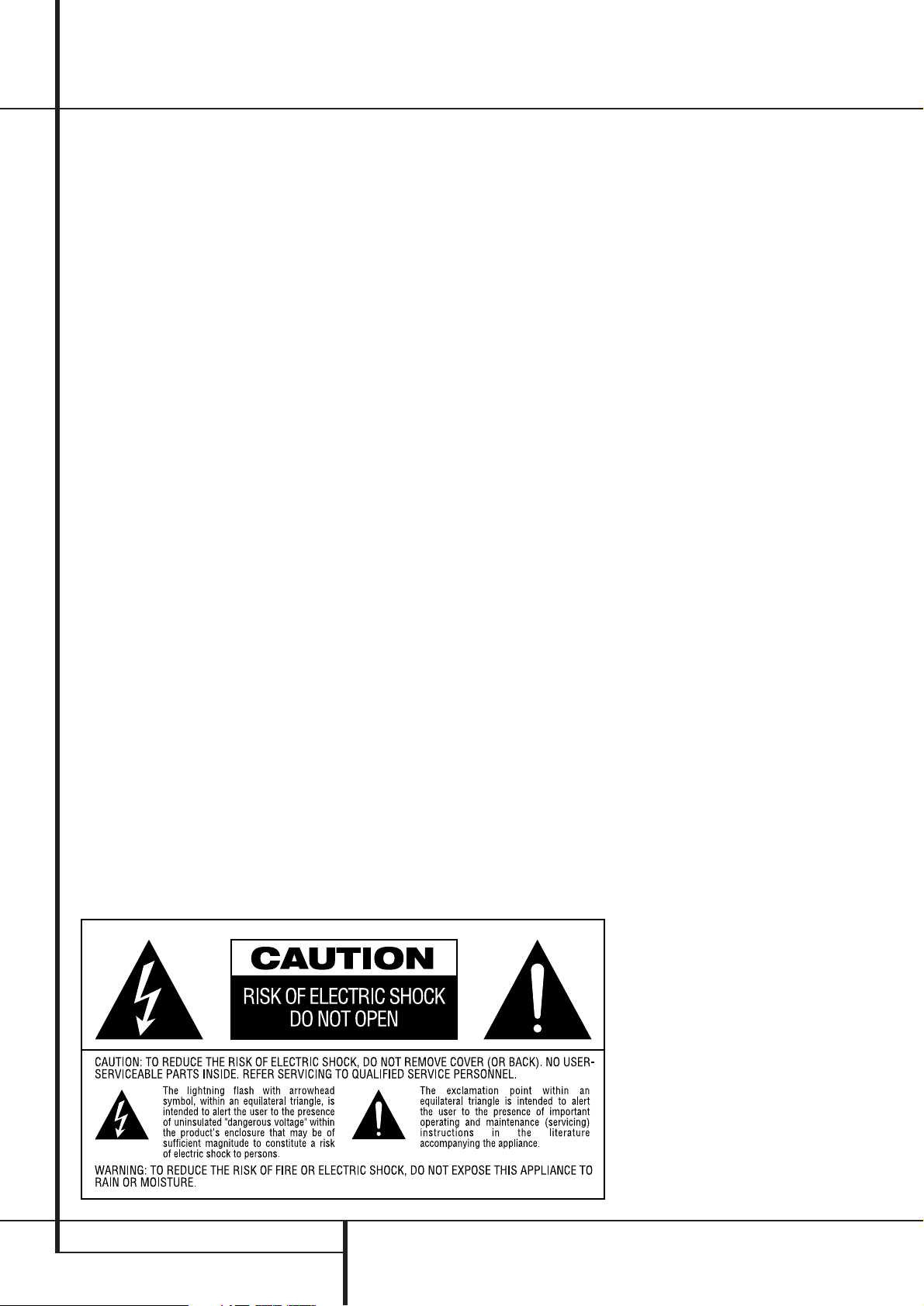
4 SAFETY INFORMATION
Safety Information
Important Safety Information
Verify Line Voltage Before Use
Your AVR has been designed for use with 220240-Volt AC current. Connection to a line
voltage other than that for which it is intended
can create a safety and fire hazard and may
damage the unit.
If you have any questions about the voltage
requirements for your specific model, or about
the line voltage in your area, contact your dealer
before plugging the unit into a wall outlet.
Do Not Use Extension Cords
To avoid safety hazards, use only the power cord
attached to your unit. We do not recommend
that extension cords be used with this product.
As with all electrical devices, do not run power
cords under rugs or carpets or place heavy
objects on them. Damaged power cords should
be replaced immediately by an authorized
service depot with a cord meeting factory
specifications.
Handle the AC Power Cord Gently
When disconnecting the power cord from an AC
outlet, always pull the plug, never pull the cord.
If you do not intend to use the unit for any
considerable length of time, disconnect the plug
from the AC outlet.
Do Not Open the Cabinet
There are no user-serviceable components inside
this product. Opening the cabinet may present a
shock hazard, and any modification to the
product will void your guarantee. If water or any
metal object such as a paper clip, wire or a
staple accidentally falls inside the unit,
disconnect it from the AC power source
immediately, and consult an authorized service
station.
Installation Location
■ To assure proper operation and to avoid the
potential for safety hazards, place the unit on
a firm and level surface.When placing the
unit on a shelf, be certain that the shelf and
any mounting hardware can support the
weight of the product.
■ Make certain that proper space is provided
both above and below the unit for ventilation.
If this product will be installed in a cabinet or
other enclosed area, make certain that there
is sufficient air movement within the cabinet.
Under some circumstances a fan may be
required.
■ Do not place the unit directly on a carpeted
surface.
■ Avoid installation in extremely hot or cold
locations, or an area that is exposed to direct
sunlight or heating equipment.
■ Avoid moist or humid locations.
■ Do not obstruct the ventilation slots on the
top of the unit, or place objects directly over
them.
Cleaning
When the unit gets dirty, wipe it with a clean,
soft, dry cloth. If necessary, wipe it with a soft
cloth dampened with mild soapy water, then a
fresh cloth with clean water. Wipe dry
immediately with a dry cloth. NEVER use
benzene, aerosol cleaners, thinner, alcohol or any
other volatile cleaning agent. Do not use
abrasive cleaners, as they may damage the finish
of metal parts.Avoid spraying insecticide near
the unit.
Moving the Unit
Before moving the unit, be certain to disconnect
any interconnection cords with other
components, and make certain that you
disconnect the unit from the AC outlet.
Unpacking
The carton and shipping materials used to
protect your new receiver during shipment were
specially designed to cushion it from shock and
vibration. We suggest that you save the carton
and packing materials for use in shipping if you
move, or should the unit ever need repair.
To minimize the size of the carton in storage,
you may wish to flatten it. This is done by
carefully slitting the tape seams on the bottom
and collapsing the carton. Other cardboard
inserts may be stored in the same manner.
Packing materials that cannot be collapsed
should be saved along with the carton in a
plastic bag.
If you do not wish to save the packaging
materials, please note that the carton and other
sections of the shipping protection are
recyclable. Please respect the environment and
discard those materials at a local recycling
center.
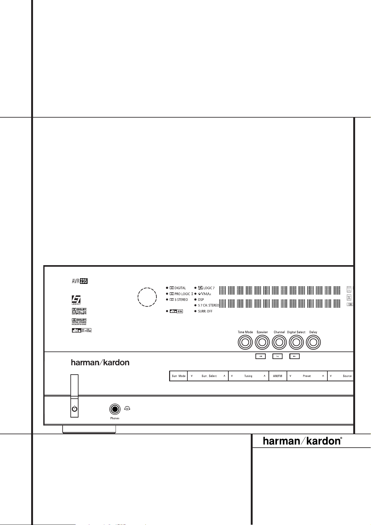
FRONT PANEL CONTROLS 5
1
Main Power Switch: Press this button to
apply power to the AVR. When the switch is
pressed in, the unit is placed in a Standby
mode, as indicated by the orange LED
3
. This
button MUST be pressed in to operate the unit.
To turn the unit off completely and prevent the
use of the remote control, this switch should be
pressed until it pops out from the front panel so
that the word “OFF” may be read at the top of
the switch.
NOTE: This switch is normally left in the “ON”
position.
2
System Power Control: When the Main
Power Switch
1
is “ON,” press this button to
turn on the AVR; press it again to turn the unit
off (to Standby). Note that the Power Indicator
3
will turn blue when the unit is on.
3
Power Indicator: This LED will be illuminated
in orange when the unit is in the Standby mode
to signal that the unit is ready to be turned on.
When the unit is in operation, the indicator will
turn blue.
4
Headphone Jack: This jack may be used to
listen to the AVR’s output through a pair of headphones. Be certain that the headphones have a
standard 6.3 mm stereo phone plug. Note that
the speakers will automatically be turned off
when the headphones are connected.
5
Surround Mode Group Selector: Press
this button to select the top-level group of
surround modes. Each press of the button will
select a major mode grouping in the following
order:
Dolby Modes ➜ DTS Digital Modes ➜ DSP
Modes ➜ Stereo Modes ➜ Logic 7 Modes
Once the button is pressed so that the name of
the desired surround mode group appears in the
Main Information Display
˜
, press the
Surround Mode Selector
9
to cycle through
the individual modes available. For example, press
this button to select Dolby modes, and then press
the Surround Mode Selector
9
to choose
from the various mode options.
6
Speaker Select Button: Press this button
to begin the process of selecting the speaker
positions that are used in your listening room.
(See page 16 for more information on setup and
configuration.)
Front Panel Controls
1
2
3
4
5
6
7
8
9
)
!
@
#
$
%
^
&
*
(
Ó
Ô
Ò
Ú
Û
Ù
ı
ˆ
˜
¯
Main Power Switch
System Power Control
Power Indicator
Headphone Jack
Surround Mode Group Selector
Speaker Select Button
Selector Buttons
Tone Mode
Surround Mode Selector
Tuning
Tuner Band Selector
Set Button
Preset Stations Selector
Speaker/Channel Input Indicator
Input Source Selector
RDS Select Button
Delay
Digital Optical 3 Input
Surround Mode Indicators
Digital Coax 3 Input
Video 4 input jacks
Bass Control
Balance Control
Treble Control
Digital Input Selector
Channel Select Button
Volume Control
Input Indicators
Main Information Display
Remote Sensor Window
AVR 235
2
4
8
6
5
)
!
@
%
*
Ô
Ò
1
3
9
7
#
^
Ù
(
˜
ˆ
&
¯
Ú
ı
Ó
7
$
Û

6 FRONT PANEL CONTROLS
Front Panel Controls
7
Selector Buttons: When you are establishing
the AVR’s configuration settings, use these buttons
to select from the choices available, as shown in
the Main Information Display
˜
.
8
Tone Mode: Pressing this button enables or
disables the Balance, Bass and Treble tone
controls.When the button is pressed so that the
words
TONE IN appear in the Main
Information Display
˜
, the settings of the
Bass
and TrebleÚcontrols and of the
Balance control
Ò
will affect the output
signals.When the button is pressed so that the
words
TONE OUT appear in the Main
Information Display
˜
, the output signal will
be “flat,” without any balance, bass or treble
alteration.
9
Surround Mode Selector: Press this button
to select from among the available surround
mode options for the mode group selected. The
specific modes will vary based on the number of
speakers available, the mode group and if the
input source is digital or analog. For example,
press the Surround Mode Group Selector
5
to select a mode grouping such as Dolby or Logic
7, and then press this button to see the mode
choices available. For more information on mode
selection, see page 29.
)
Tuning Selector: Press the left side of the
button to tune lower frequency stations and the
right side of the button to tune higher frequency
stations.When a station with a strong signal is
reached,
MANUAL TUNED or AUTO
TUNED
will appear in the Main Information
Display
˜
(see page 35 for more information
on tuning stations).
!
Tuner Band Selector: Pressing this button
will automatically switch the AVR to the Tuner
mode. Pressing it again will switch between the
AM and FM frequency bands, holding it pressed
for some seconds will switch between stereo and
mono receiving and between automatic and
manual tuning mode (See page 35 for more
information on the tuner).
@ Set Button: When making choices during the
setup and configuration process, press this button
to enter the desired setting as shown in the
Main Information Display
˜
into the AVR’s
memory.The set button may also be used to
change the display brightness (See page 33).
#
Preset Stations Selector: Press this
button to scroll up or down through the list of
stations that have been entered into the preset
memory (See page 35 for more information on
tuner programming).
$
Speaker/Channel Input Indicators: These
indicators are multipurpose, indicating either the
speaker type selected for each channel or the
incoming data-signal configuration.The left,center,
right, right surround and left surround speaker
indicators are composed of three boxes, while the
subwoofer is a single box. The center box lights
when a “Small” speaker is selected, and the two
outer boxes light when “Large” speakers are
selected. When none of the boxes are lit for the
center, surround or subwoofer channels, no speaker
has been selected for that position. (See page 17
for more information on configuring speakers.) The
letters inside each of the center boxes display
active input channels. For standard analog inputs,
only the L and R will light, indicating a stereo
input. When a digital source is playing, the indicators will light to display the channels begin
received at the digital input. When the letters
flash, the digital input has been interrupted. (See
page 19 for more information on the Channel
Indicators).
%
Input Source Selector: Press this button to
change the input by scrolling through the list of
input sources.
^
RDS Select Button: Press this button to
display the various messages that are part of the
RDS data system of the AVR’s tuner.
(See page 36 for more information on RDS).
&
Delay: Press this button to begin the
sequence of steps required to enter delay time
settings (See page 22 for more information on
delay times).
*
Digital Optical 3 Input: Connect the optical
digital audio output of an audio or video product
to this jack. When the Input is not in use, be
certain to keep the plastic cap installed to avoid
dust contamination that might degrade future
performance.
(
Surround Mode Indicators: The current
selected mode or function will appear as one of
these indicators. Note that when the unit is
turned on, the entire list of available modes will
light briefly, and then revert to normal operation
with only the active mode indicator illuminated.
Ó
Digital Coax 3 Input: This jack is normally
used for connection to the output of portable
digital audio devices, video game consoles or
other products that have a coax digital jack.
Ô
Video 4 Input Jacks: These audio/video
jacks may be used for temporary connection to
video games or portable audio/video products
such as camcorders and portable audio players.
Bass Control: Turn this control to modify the
low frequency output of the left/right channels by
as much as ±10dB. Set this control to a suitable
position for your taste or room acoustics.
Ò
Balance Control: Turn this control to
change the relative volume for the front left/right
channels.
NOTE: For proper operation of the surround
modes this control should be at the midpoint or
“12 o’clock” position.
Ú
Treble Control: Turn this control to modify
the high frequency output of the left/right channels
by as much as ±10dB. Set this control to a suitable
position for your taste or room acoustics.
Û
Digital Input Selector: When playing a
source that has a digital output, press this button
to select between the Optical
and Coaxial
Digital inputs. (See pages 20-22 for more
information on digital audio).
Ù
Channel Select Button: Press this button
to begin the process of trimming the channel
output levels using an external audio source.
(For more information on output level trim
adjustment, see page 32).
ı
Volume Control:Turn this knob clockwise
to increase the volume, counterclockwise to
decrease the volume. If the AVR is muted, adjusting volume control will automatically release the
unit from the silenced condition.
ˆ
Input indicators: The current selected
mode or function will appear as one of these
indicators. Note that when the unit is turned on,
the entire list of available modes will light briefly,
and then revert to normal operation with only
the active mode indicator illuminated.
˜
Main Information Display: This display
delivers messages and status indications to help
you operate the receiver.
¯
Remote Sensor Window:The sensor
behind this window receives infrared signals from
the remote control. Aim the remote at this area
and do not block or cover it unless an external
remote sensor is installed.
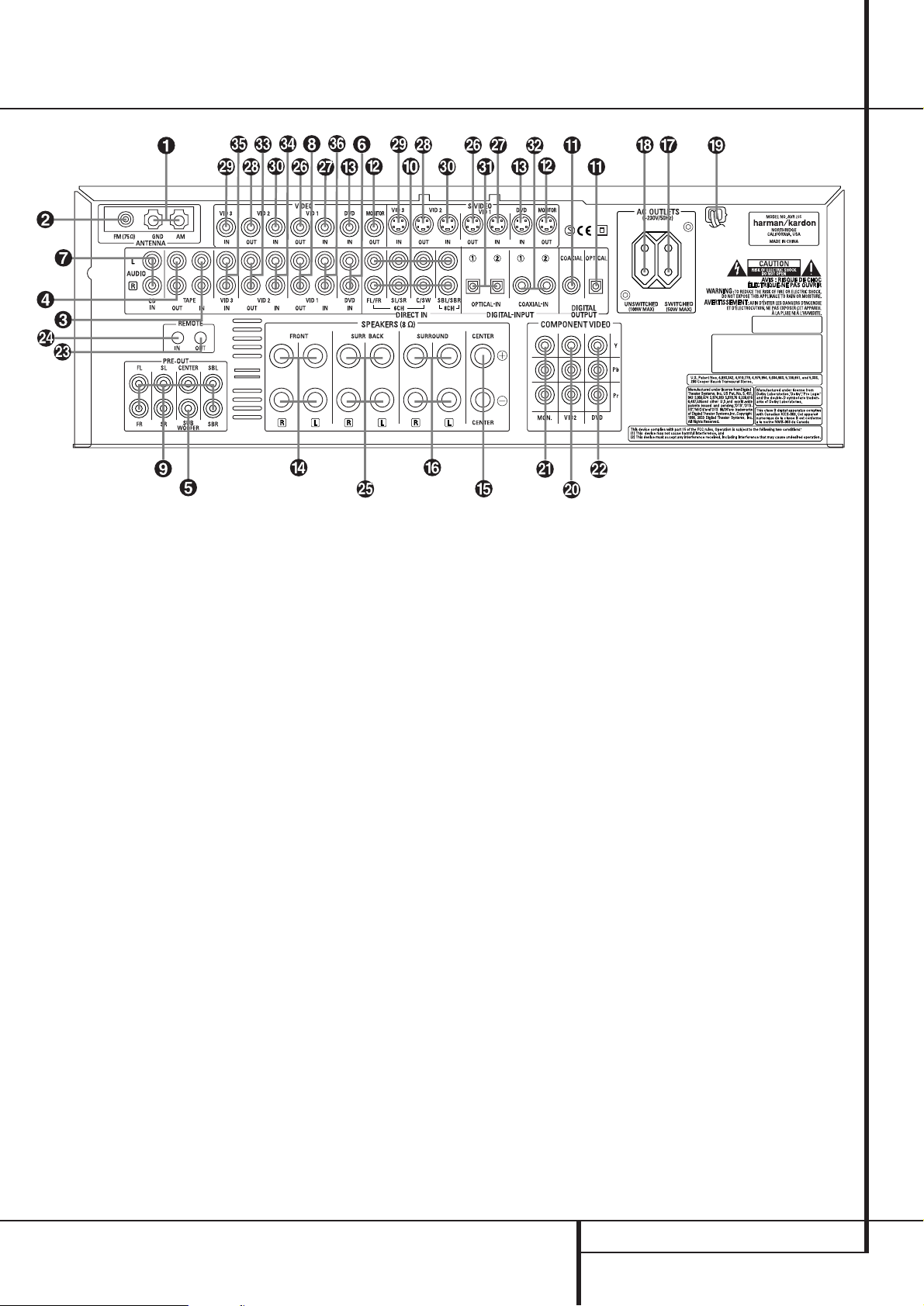
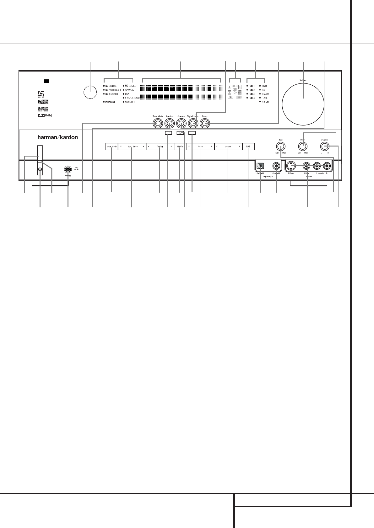
REAR PANEL CONNECTIONS 7
Rear Panel Connections
!
»
#
$
%
AM Antenna
FM Antenna
Tape Inputs
Tape Outputs
Subwoofer Output
DVD Audio Inputs
CD Inputs
Video 1 Audio Outputs
Preamp Outputs
8-Channel Direct Inputs
Digital Audio Outputs
Video Monitor Outputs
DVD Video Inputs
Front Speaker Outputs
Center Speaker Outputs
Surround Speaker Outputs
Switched AC Accessory Outlet
Unswitched AC Accessory Outlet
AC Power Cord
Video 2 Component Video Inputs
Component Video Outputs
DVD Component Video Inputs
Remote IR Output
Remote IR Input
Surround Back Speaker Outputs
Video 1 Video Outputs
Video 1 Video Inputs
Video 2 Video Outputs
Video 3 Video Inputs
Video 2 Video Inputs
Optical Digital Inputs
Coaxial Digital Inputs
Video 2 Audio Outputs
Video 2 Audio Inputs
Video 3 Audio Inputs
Video 1 Audio Inputs
NOTE: To assist in making the correct connections for multichannel input/output and speaker
connections, all connection jacks and terminals
have been color coded in conformance with the
latest CEA standards as follows:
Front Left: White
Front Right: Red
Center: Green
Surround Left: Blue
Surround Right: Gray
Surround Back Left: Brown
Surround Back Right: Tan
Subwoofer (LFE): Purple
Digital Audio: Orange
Composite Video: Yellow
Component Video “Y”: Green
Component Video “Pr”: Red
Component Video “Pb”: Blue
AM Antenna: Connect the AM loop antenna
supplied with the receiver to these terminals. If an
external AM antenna is used, make connections to
the AM and GND terminals in accordance with
the instructions supplied with the antenna.
FM Antenna: Connect the supplied indoor or
an optional external FM antenna to this terminal.
Tape Inputs: Connect these jacks to the
PLAY/OUT jacks of an audio recorder.
Tape Outputs: Connect these jacks to the
RECORD/INPUT jacks of an audio recorder.
Subwoofer Output: Connect this jack to
the line-level input of a powered subwoofer. If an
external subwoofer amplifier is used, connect this
jack to the subwoofer amplifier input.
DVD Audio Inputs: Connect these jacks to
the analog audio jacks on a DVD or other audio
or video source.
CD Inputs: Connect these jacks to the
analog output of a compact disc player or CD
changer or any other audio source.
Video 1 Audio Outputs: Connect these
jacks to the RECORD/INPUT audio jacks on
a VCR or any other Audio recorder.
Preamp Outputs: Connect these jacks to
an optional, external power amplifier for applications where higher power is desired.
8-Channel Direct Inputs: These jacks are
used for connection to source devices such as
DVD-Audio or SACD players with discrete analog
outputs. Depending on the source device in use,
all eight jacks may be used, though in many
cases only connections to the front left/right,
center, surround left/right and LFE (subwoofer
input) jacks will be used for standard 5.1 audio
signals.
Digital Audio Outputs: Connect these
jacks to the matching digital input connector on
a digital recorder such as a CD-R or MiniDisc
recorder.

8 REAR PANEL CONNECTIONS
Rear Panel Connections
Video Monitor Outputs: Connect this jack
to the composite and/or S-Video input of a TV
monitor or video projector to view the on-screen
menus and the output of any standard Video or
S-Video source selected by the receiver’s video
switcher.
DVD Video Inputs: Connect these jacks to
the composite or S-Video output jacks on a DVD
player or other video source.
Front Speaker Outputs: Connect these
outputs to the matching + or – terminals on
your left and right speakers. In conformance with
the new CEA color code specification, the White
terminal is the positive, or «+» terminal that
should be connected to the red (+) terminal on
Front Left speaker with the older color coding,
while the Red terminal is the positive, or «+»
terminal that should be connected to the red (+)
terminal on Front Right speaker. Connect the
black (–) terminals on the AVR to the black (–)
terminals on the speakers. See page 12 for more
information on speaker polarity.
Center Speaker Outputs: Connect these
outputs to the matching + and – terminals on
your center channel speaker. In conformance
with the new CEA color code specification, the
Green Terminal is the positive, or «+» terminal
that should be connected to the red (+) terminal
on speakers with the older color coding. Connect
the black (–) terminal on the AVR to the black
negative (–) terminal on your speaker. (See page
12 for more information on speaker polarity.)
Surround Speaker Outputs: Connect
these outputs to the matching + and – terminals
on your surround channel speakers. In conformance with the new CEA color code specification, the Blue terminal is the positive, or «+»
terminal that should be connected to the red (+)
terminal on the Surround Left speaker with older
color coding, while the Gray terminal should be
connected to the red (+) terminal on the
Surround Right speaker with the older color
coding. Connect the black (–) terminal on the
AVR to the matching black negative (–)
terminals for each surround speaker. (See page
12 for more information on speaker polarity.)
Switched AC Accessory Outlet: This
outlet may be used to power any device that you
wish to have turn on when the AVR is turned on
with the System Power Control switch
2
.
Unswitched AC Accessory Outlet: This
outlet may be used to power any AC device. The
power will remain on at this outlet regardless of
whether the AVR is on or off (in Standby), provided that the Main Power switch
1
is on.
Note: The total power consumption of all
devices connected to the accessory outlets
should not exceed 100 watts from the
Unswitched Outlet
and 50 W from the
Switched Outlet
.
AC Power Cord: Connect the AC plug to an
unswitched AC wall output.
Video 2 Component Video Inputs:
Connect the Y/Pr/Pb component video outputs of
an HDTV Set-top convertor, satellite receiver, or
other video source device with component video
outputs to these jacks.
Monitor Component Video Outputs:
Connect these outputs to the component video
inputs of a video projector or monitor. When a
source connected to one of the two
Component Video Inputs
is selected
the signal will be sent to these jacks.
DVD Component Video Inputs: Connect
the Y/Pr/Pb component video outputs of a DVD
player to these jacks.
Note: All component inputs/outputs can be
used for RGB signals too, in the same way as
described for the Y/Pr/Pb signals, then connected
to the jacks with the corresponding color.
RGB connection is not possible if the source outputs a separate sync signal (see page 13).
Remote IR Output: This connection permits
the IR sensor in the receiver to serve other
remote controlled devices. Connect this jack to
the “IR IN” jack on Harman Kardon or other
compatible equipment.
Remote IR Input: If the AVR’s front-panel
IR sensor is blocked due to cabinet doors or
other obstructions, an external IR sensor may
be used. Connect the output of the sensor to
this jack.
Surround Back Speaker Outputs: These
speaker terminals are used to power the
surround back left/surround back right speakers
in a 7.1 channel system. In normal surround
system use, the brown and black terminals are
the surround back left channel positive (+) and
negative (–) connections and the tan and black
terminals are the surround back right positive
(+) and negative (–) terminals.
Video 1 Video Outputs: Connect these
jacks to the RECORD/INPUT composite or
S-Video jack on a VCR.
Video 1 Video Inputs: Connect these jacks
to the PLAY/OUT composite or S-Video jacks on
a VCR or other video source.
Video 2 Video Outputs: Connect these
jacks to the RECORD/INPUT composite or
S-Video jacks on a second VCR.
Video 3 Video Inputs: Connect these jacks
to the PLAY/OUT composite or S-Video jacks on
any video source.
Video 2 Video Inputs: Connect these jacks
to the PLAY/OUT composite or S-Video jacks on
a second VCR or other video source.
Optical Digital Inputs: Connect the
optical digital output from a DVD player, HDTV
receiver, the output of a compatible computer
sound card playing MP3 files or streams, LD
player, MD player or CD player to these jacks.
The signal may be either a Dolby Digital signal, a
DTS signal, a 2 channel MPEG 1 signal, or a
standard PCM digital source.
!
Coaxial Digital Inputs: Connect the coax
digital output from a DVD player, HDTV receiver,
the output of a compatible computer sound card
playing MP3 files or streams, LD player, MD
player or CD player to these jacks.The signal
may be either a Dolby Digital signal, DTS signal,
a 2 channel MPEG 1 signal, or a standard PCM
digital source. Do not connect the RF digital output of an LD player to these jacks.
«
Video 2 Audio Outputs: Connect these
jacks to the RECORD/INPUT audio jacks on a
VCR or any Audio recorder.
#
Video 2 Audio Inputs: Connect these jacks
to the PLAY/OUT audio jacks on a second VCR
or other audio or video source.
$
Video 3 Audio Inputs: Connect these jacks
to the PLAY/OUT audio jacks on any audio or
video source.
%
Video 1 Audio Inputs: Connect these jacks
to the PLAY/OUT audio jacks on a VCR or other
audio or video source.
0
1
2
3
4
5
6
7
8
9
A
B
C
D
E
F
G
H
I
J
K
L
M
N
O
P
Q
!
»
#
$
%
&
‘
(
)
*
+
,
—
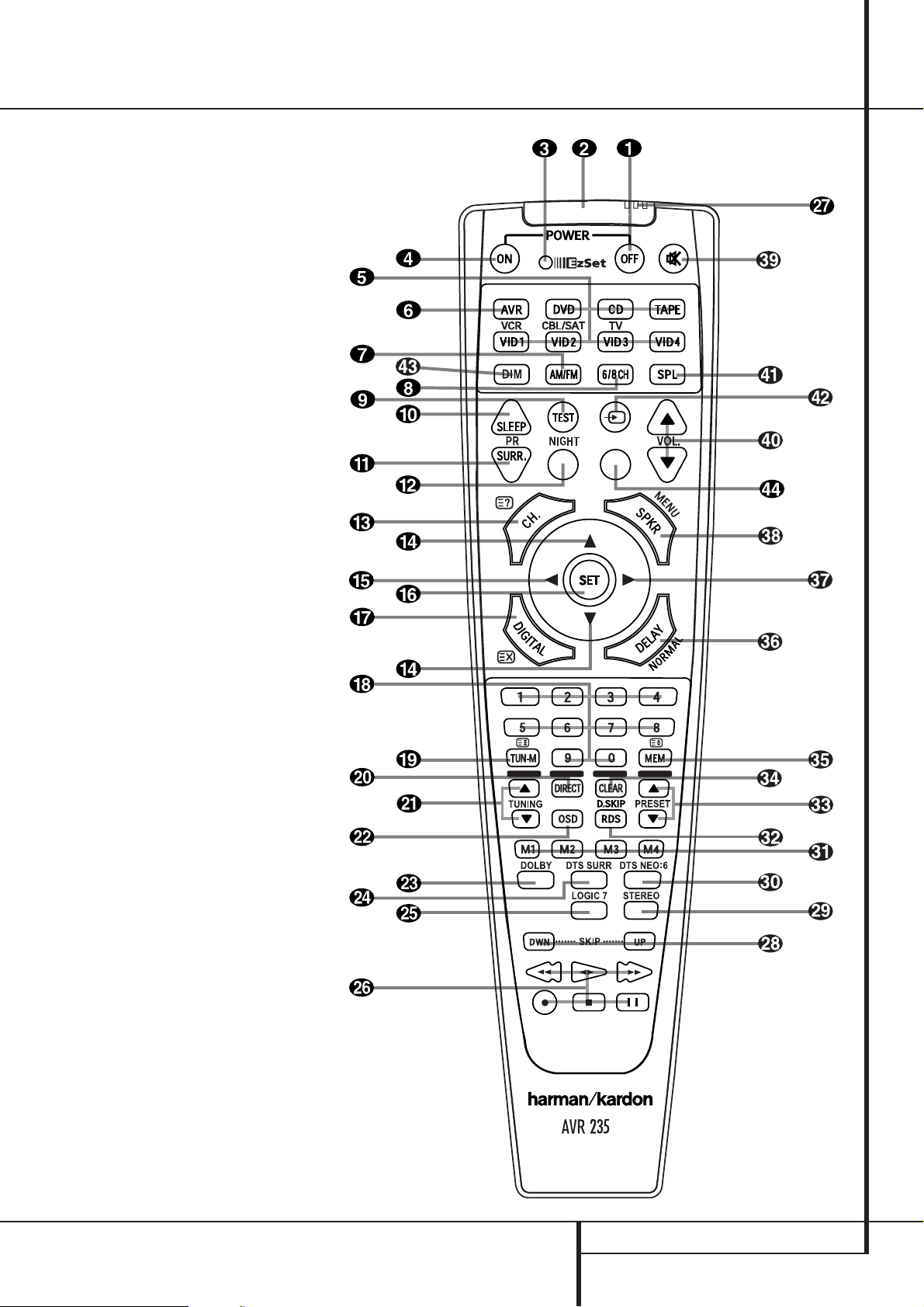
MAIN REMOTE CONTROL FUNCTIONS 9
Main Remote Control Functions
Power Off Button
IR Transmitter Window
Program/SPL Indicator
Power On Button
Input Selectors
AVR Selector
AM/FM Tuner Select
6-Channel/8-Channel Direct Input
Test Button
Sleep Button
Surround Mode Selector
Night Mode
Channel Select Button
⁄/¤
Buttons
‹
Button
Set Button
Digital Select
Numeric Keys
Tuner Mode
Direct Button
Tuning Up/Down
OSD Button
Dolby Mode Select Button
DTS Digital Mode Selector
Logic 7 Mode Select Button
Transport Controls
EzSet Sensor Microphone
Skip Up/Down Buttons
Stereo Mode Select Button
DTS Neo:6 Mode Select
Macro Buttons
RDS Selector Button
Preset Up/Down
Clear Button
Memory Button
Delay/Prev. Ch.
›
Button
Speaker Select
Mute
Volume Up/Down
SPL Indicator Select
TV/Video Selector
Dim Button
Spare Button
NOTE: The function names shown here are each
button’s feature when used with the AVR. Most
buttons have additional functions when used
with other devices. See page 40-41 for a list of
these functions.
10 MAIN REMOTE CONTROL FUNCTIONS
Main Remote Control Functions
IMPORTANT NOTE: The AVR 235’s remote may
be programmed to control up to seven devices,
including the AVR. Before using the remote, it is
important to remember to press the Input
Selector button
4
that corresponds to the unit
you wish to operate. In addition, the AVR’s remote
is shipped from the factory to operate the AVR and
most Harman Kardon CD or DVD players and cassette decks.The remote is also capable of operating a wide variety of other products using the
control codes that are part of the remote. Before
using the remote with other products, follow the
instructions on pages 37-39 to program the proper codes for the products in your system.
It is also important to remember that many of the
buttons on the remote take on different
functions, depending on the product selected
using the Input Selector Button
4
.The
descriptions shown here primarily detail the functions of the remote when it is used to operate the
AVR. (See page 40 for information about alternate functions for the remote’s buttons.)
0
Power Off Button: Press this button to
place the AVR or a selected device unit in the
Standby mode. Note that when the AVR is
switched off this will turn off the main room
functions, but if the Multiroom system is activated,
it will continue to function.
1
IR Transmitter Window: Point this window
towards the AVR when pressing buttons on the
remote to make certain that infrared commands are
properly received.
2
Program/SPL Indicator: This three-color
indicator is used to guide you through the process
of programming the remote it is also used as a
level indicator when using the remote’s EzSet
capabilities. (See page 23 for more information on
setting output levels, and see page 37 for information on programming the remote.)
3
Power On Button: Press this button to turn
on the power to a device selected by pressing one
of the Input Selectors
4
(except Tape).
4
Input Selectors: Pressing one of these buttons will perform three actions at the same time.
First, if the AVR is not turned on, this will power
up the unit. Next, it will select the source shown
on the button as the input to the AVR. Finally, it
will change the remote control so that it controls
the device selected. After pressing one of these
buttons you must press the AVR Selector
button
5
again to operate the AVR’s functions
with the remote.
5
AVR Selector: Pressing this button will
switch the remote so that it will operate the AVR’s
functions. If the AVR is in the Standby mode, it will
also turn the AVR on.
6
AM/FM Tuner Select: Press this button to
select the AVR’s tuner as the listening choice.
Pressing this button when the tuner is in use will
select between the AM and FM bands.
7
6-Channel/8 Channel Direct Input:
Press this button to select the device connected to
the 6-Channel Direct Inputs or the
8-Channel Direct Inputs
(the input
available will depend on the selection 5.1 or
6.1/7.1 made in the surround mode setting,
see page 28 for more information).
8
Test Tone: Press this button to begin the
sequence used to calibrate the AVR’s output levels.
(See page 23 for more information on calibrating
the AVR).
9
Sleep Button: Press this button to place the
unit in the Sleep mode.After the time shown in
the display, the AVR will automatically go into the
Standby mode. Each press of the button changes
the time until turn-off in the following order:
Hold the button pressed for two seconds to turn
off the Sleep mode setting.
Note that this button is also used to change
channels on your TV, VCR and Sat receiver when
the appropriate source is selected, using the
device Input Selectors
4
.
A
Surround Mode Selector: Press this button to select any of the HALL, THEATER or VMAx
surround modes. Note that depending on the
type of input, some modes are not always available. (See page 26 for more information about
surround modes.) Note that this button is also
used to tune channels on your TV, VCR and Sat
receiver when the appropriate source is selected
using the device Input Selector
4
.
B
Night Mode: Press this button to activate
the Night mode.This mode is available only with
Dolby Digital encoded sources, and it preserves
dialog (center channel) intelligibilty at low volume levels (See page 23 for more information).
C
Channel Select Button: This button is
used to start the process of setting the AVR’s
output levels with an external source. Once this
button is pressed, use the
⁄/¤
buttons Dto
select the channel being adjusted, then press the
Set button
F
, followed by the
⁄/¤
buttons
D
again, to change the level setting.
(See page 31 for more information.)
D
⁄/¤
Buttons: These multipurpose buttons
are used to change or scroll through items in the
on-screen menus or on the front panel or to
make configuration settings such as digital inputs
or delay timing. When changing a setting, first
press the button for the function or setting to be
changed (e.g., press the Digital Select Button
G
to change a digital input) and then press
one of these buttons to scroll through the list of
options or to increase or decrease a setting. The
sections in this manual describing the individual
features and functions contain specific information on using these buttons for each application.
When the AVR remote is being programmed for
the codes of another device, these buttons are also
used in the “Auto Search” process (See page 37
for more information on programming the remote.)
E‹Button: This button is used to change the
menu selection or setting during some of the
setup procedures for the AVR.
F
Set Button: This button is used to enter
settings into the AVR’s memory. It is also used in
the setup procedures for delay time, speaker configuration and channel output level adjustment.
G
Digital Select: Press this button to assign
one of the digital inputs
!*Ó
to a source.
(See page 30 for more information on using
digital inputs.)
H
Numeric Keys: These buttons serve as a
ten-button numeric keypad to enter tuner preset
positions.They are also used to select channel
numbers when TV, VCR or Sat receiver has been
selected on the remote, or to select track numbers on a CD, DVD or LD player, depending on
how the remote has been programmed.
I
Tuner Mode: Press this button when the
tuner is in use to select between automatic
tuning and manual tuning. When the button is
pressed so
MANUAL appears in the Main
Information Display
˜
, pressing the Tuning
buttons
K)will move the frequency up or
down in single-step increments.When the FM
band is in use and
AUTO appears in the Main
Information Display
˜
, pressing this button
will change to monaural reception making even
week stations audible. (See page 35 for more
information.)
J
Direct Button: Press this button when the
tuner is in use to start the sequence for direct
entry of a station’s frequency. After pressing the
button simply press the proper Numeric Keys
H
to select a station (See page 35 for more
information on the tuner).
K
Tuning Up/Down: When the tuner is in use,
these buttons will tune up or down through the
selected frequency band. If the Tuner Mode but-
ton
I
has been pressed or the Band button
!
on the front panel was held pressed so that
AUTO appears in the Main Information
Display
˜
, pressing either of the buttons will
cause the tuner to seek the next station with
acceptable signal strength for quality reception.
When the
MANUAL appears in the Main
Information Display
˜
, pressing these buttons will tune stations in single-step increments.
(See page 35 for more information.)
L
OSD Button: Press this button to activate
the On Screen Display (OSD) system used to set
up or adjust the AVR’s parameters.
90
min80min70min60min50min
40
min
30
min20min10min
OFF

MAIN REMOTE CONTROL FUNCTIONS 11
M
Dolby Mode Selector: This button is used
to select one of the available Dolby Surround
processing modes. Each press of this button will
select one of the Dolby Pro Logic II modes, Dolby
3 Stereo or Dolby Digital. Note that the Dolby
Digital mode is only available with a digital input
selected and the other modes only as long as a
Dolby Digital source is not playing (except Pro
Logic II with Dolby Digital 2.0 recordings, see
page 31). See page 25 for the available Dolby surround mode options.
N
DTS Digital Mode Selector: When a DTS
source is in use the AVR will select the appropriate mode automatically and no other mode will
be available. Pressing this button will display the
mode currently selected by the AVR´s decoder,
depending on the surround material played and
the speaker setting.When a DTS source is not in
use, this button has no function. (See page 26 for
the available DTS options.)
O
Logic 7 Selector: Press this button to select
one of the available Logic 7 surround modes. (See
page 26 for the available Logic 7 options.)
P
Transport Control Buttons: These buttons
do not have any functions for the AVR, but they
may be programmed for the forward/reverse play
operation of a wide variety of CD or DVD players,
and audio or video- cassette recorders. (See page
40 for more information on programming the
remote.)
Q
EzSet Sensor Microphone: The sensor
microphone for the EzSet microphone is behind
these slots.When using the remote to calibrate
speaker output levels using EzSet, be sure that
you do not hold the remote in a way that covers
these slots. (See page 23 for more information on
using EzSet).
Skip Up/Down Buttons: These buttons do
not have a direct function with the AVR, but
when used with a compatibly programmed CD or
DVD player/changer they will change the tracks
on the disc currently being played.
Stereo Mode Selector: Press this button
to select a stereo playback mode.When the button is pressed so that
DSP SURR OFF
appears in the Main Information Display˜,
the AVR will operate in a bypass mode with true
fully analog, two-channel left/right stereo mode
with no surround processing or bass management as opposed to other modes where digital
processing is used. When the button is pressed so
that
SURROUND OFF appears in the Main
Information Display
˜
, you may enjoy a twochannel presentation of the sound along with the
benefits of bass management. When the button
is pressed so that
5 C H STEREO or
7 C H STEREO appears, the stereo signal is
routed to all five speakers, if installed.(See page
21 for more information on stereo playback
modes).
DTS Neo:6 Mode Selector: Pressing this
selector button cycles the AVR through the
various DTS Neo:6 modes, which extract a five- or
seven-channel surround field from two-channel
program material (from PCM source or analog
input signal). The first press selects the last DTS
Neo:6 surround mode that was in use, and each
subsequent press selects the next mode.
Macro Buttons: Press these buttons to
store or recall a “Macro”, which is a pre-programmed sequence of commands stored in the
remote. (See page 38 for more information on
storing and recalling macros).
!
RDS Select Button: Press this button to display the various messages that are part of the RDS
data system of the AVR’s tuner. (See page 36 for
more information on RDS).
«
Preset Up/Down: When the tuner is in use,
press these buttons to scroll through the stations
programmed into the AVR’s memory.When CD or
DVD is selected using the Input Selector button
4
, these buttons may function as Slow
Fwd/Rev (DVD) or ”+10” (CD, CDR).
#
Clear Button: Press this button to clear
incorrect entries when using the remote to directly
enter a radio station’s frequency.
$
Memory Button: Press this button to enter a
radio station into the AVR ’s preset memory. Two
underline indicators will flash at the right side of
the Main Information Display
˜
, you then
have five seconds to enter a preset memory location using the Numeric Keys
H
. (See page 35
for more information).
%
Delay/Prev Ch.: Press this button to begin
the process for setting the delay times used by
the AVR when processing surround sound. After
pressing this button, the delay times are entered
by pressing the Set button
F
and then using
the
⁄/¤
buttons Dto change the setting.
Press the Set button again to complete the
process. (See page 22 for more information).
&›Button: Press this button to change a setting or selection when configuring many of the
AVR’s settings.
‘
Speaker Select: Press this button to begin
the process of configuring the AVR’s Bass
Management System for use with the type of
speakers used in your system. Once the button
has been pressed, use the
⁄/¤
buttons Dto
select the channel you wish to set up.
Press the Set Button
F
and then select the
speaker type (Large, Small or None) appropriate
with the speaker in use. (See page 17 for more
information).
(
Mute: Press this button to momentarily
silence the AVR or TV set being controlled,
depending on which device has been selected.
When the AVR remote is being programmed to
operate another device, this button is pressed with
the Input Selector button
4
to begin the programming process. (See page 37 for more information on programming the remote).
)
Volume Up/Down: Press these buttons to
raise or lower the system volume.
*
SPL Indicator Select: This button activates
the AVR’s EzSet function to quickly and accurately
calibrate the AVR’s output levels. During this
sequence, EzSet will automatically adjust the output levels for all channels until they are equal, as
shown by the Program Indicator
2
lighting
green for each channel. (See page 23 for more
information on EzSet).
+
TV/Video Button: This button does not
have a direct function on the AVR, but when used
with a compatibly programmed VCR, DVD or
satellite receiver that has a “TV/Video” function,
pressing this button will switch between the output of the player or receiver and the external
video input to that player. Consult the Owner’s
Manual for your specific player or receiver for the
details of how it implements this function.
NOTE: With the press of any remote button the
Input Selector button
45
associated
with the botton pressed will briefly flash red to
confirm the transmission of the command, as
long as there is a function for that button with
the device selected (see function list on
pages 40-41).
,
Dim Button: Press this button to activate
the Dimmer function, which reduces the brightness of the front-panel display, or turns it off
entirely. Press the button once to change the display to reduce the brightness by 50%, and press
it again within five seconds and the main display
will go completely dark. Note that this setting is
temporary; regardless of any changes, the display
will always return to full brightness when the
AVR is turned on.The blue illumination around
the Power Indicator
3
will always remain at
full brightness regardless of the setting to remind
you that the AVR is still turned on.
—
Spare Button: This button has no function
when used with the AVR. When used with the
DVD player, it controls the Subtitle On/Off function.
Main Remote Control Functions
12 INSTALLATION AND CONNECTIONS
After unpacking the unit, and placing it on a solid
surface capable of supporting its weight, you will
need to make the connections to your audio and
video equipment.
Audio Equipment Connections
We recommend that you use high-quality interconnect cables when making connections to
source equipment and recorders to preserve the
integrity of the signals.
When making connections to audio source
equipment or speakers it is always a good
practice to unplug the unit from the AC wall
outlet. This prevents any possibility of
accidentally sending audio or transient signals to
the speakers that may damage them.
1. Connect the analog output of a CD player to
the CD inputs
.
NOTE: When the CD player has both fixed and
variable audio outputs it is best to use the fixed
output unless you find that the input to the
receiver is so low that the sound is noisy, or so
high that the signal is distorted.
2. Connect the analog Play/Out jacks of a cassette deck, MD, CD-R or other audio recorder to
the Tape Input jacks
. Connect the analog
Record/In jacks on the recorder to the Tape
Output jacks
on the AVR.
3. Connect the digital output of any digital
sources such as a CD or DVD changer or player,
advanced video game, a digital satellite receiver,
HDTV tuner or digital cable set-top box or the
output of a compatible computer sound card to
the Optical and Coaxial Digital Inputs
!*Ó
.
4. Connect the Coaxial or Optical Digital
Outputs
on the rear panel of the AVR to the
matching digital input connections on a CD-R or
MiniDisc recorder.
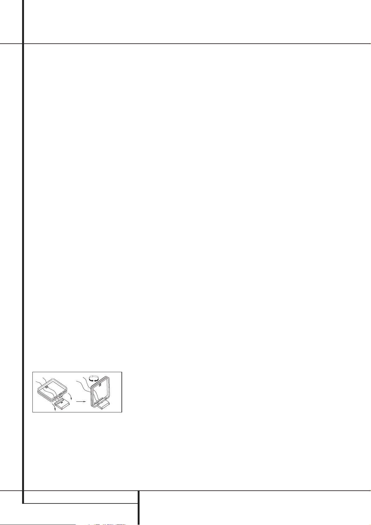
5. Assemble the AM Loop Antenna supplied with
the unit as shown below. Connect it to the AM
and GND screw terminals
.
6. Connect the supplied FM antenna to the FM
(75 ohm) connection
. The FM antenna may
be an external roof antenna, an inside powered
or wire lead antenna or a connection from a
cable system. Note that if the antenna or connection uses 300-ohm twin-lead cable, you should
use a 300-ohm-to-75-ohm adapter to make the
connection.
7. Connect the front, center and surround
speaker outputs
to the respective
speakers.
To assure that all the audio signals are carried to
your speakers without loss of clarity or
resolution, we suggest that you use high-quality
speaker cable. Many brands of cable are
available and the choice of cable may be influenced by the distance between your speakers and
the receiver, the type of speakers you use,
personal preferences and other factors.Your
dealer or installer is a valuable resource to
consult in selecting the proper cable.
Regardless of the brand of cable selected, we
recommend that you use a cable constructed of
fine, multistrand copper with an area greater than
2 mm
2
.
Cable with an area of 1.5 mm
2
may be used for
short runs of less than 4 m. We do not recommend that you use cables with an area less than
1mm
2
due to the power loss and degradation in
performance that will occur.
Cables that are run inside walls should have the
appropriate markings to indicate listing with any
appropriate testing agency standards. Questions
about running cables inside walls should be
referred to your installer or a licensed electrician
who is familiar with the applicable local building
codes in your area.
When connecting wires to the speakers, be
certain to observe proper polarity. Note that the
positive (+) terminal of each speaker connection
now carries a specific color code as noted on
page 8. However, most speakers will still use a
red terminal for the postive (+) connection.
Connect the “negative” or “black” wire to the
same terminal on both the receiver and the
speaker.
NOTE: While most speaker manufacturers
adhere to an industry convention of using black
terminals for negative and red ones for positive,
some manufacturers may vary from this configuration. To assure proper phase and optimal performance, consult the identification plate on your
speaker or the speaker’s manual to verify polarity.
If you do not know the polarity of your speaker,
ask your dealer for advice before proceeding, or
consult the speaker’s manufacturer.
We also recommend that the length of cable
used to connect speaker pairs be identical. For
example, use the same length piece of cable to
connect the front-left and front-right or
surround-left and surround-right speakers, even
if the speakers are a different distance from the
AVR.
It is appropriate to configure the AVR 235 for
either 5.1- or 7.1-channel operation, but not for
6.1 channels.When 6.1-channel program material or a 6.1-channel processing mode is in use,
material for the surround back channel will be
outputted simultaneously through both the
Surround Back Left and Right Speaker
Outputs
. Connecting only one loudspeaker
to these speaker terminals will not only deprive
you of the benefits of 7.1-channel surround
modes, such as Logic 7, but will also interfere
with the functioning of EzSet speaker calibration,
as described on page 23. It may also put undesirable strain on the surround back amplifier circuits
and power supplies.
8. Connections to a subwoofer are normally
made via a line level audio connection from the
Subwoofer Output
to the line-level input
of a subwoofer with a built-in amplifier. When a
passive subwoofer is used, the connection first
goes to a power amplifier, which will be connected to one or more subwoofer speakers. If you are
using a powered subwoofer that does not have
line-level input connections, follow the instructions furnished with the speaker for connection
information.
9. If an external multi-channel audio source with
5.1 outputs such as an external digital processor/decoder, DVD-Audio or SACD player is used,
connect the outputs of that device to the
8-Channel Direct Inputs
.
External Amplifier Connections
The AVR 235’s internal-power amplifier is a
traditional Harman Kardon high-current/
ultrawide bandwidth design. As such, it is more
than suitable for most loudspeakers. However, in
some circumstances you may wish to use an
optional, external power amplifier for added
power. This is easily done by connecting the
Preamp Output Jacks
on the AVR 235 to
the input jacks on the amplifier for the channels
to be used. The speakers to be used with the
external amplifier are then connected to the
appropriate output terminals on the power
amplifier, not those on the AVR.
When an external amplifier is used for the
Surround Back channels, no special adjustments
are needed to the AVR, other than to make
certain that the Surround Back speakers are
properly configured to “Large” or “Small,” as
shown in the Speaker Setup section on page 18
of this manual. This is necessary to tell the AVR’s
digital processing system that 6.1/7.1 modes
should be activated, as opposed to the default
setting of 5.1 modes.
Installation and Connections

INSTALLATION AND CONNECTIONS 13
Installation and Connections
9. If you have a camcorder, video game or other
audio/video device that is connected to the AVR
on a temporary, rather than permanent basis,
connect the audio, video and digital audio outputs of that device to the Front Panel Inputs
*ÓÔ
. A device connected to the Video 4
jacks
Ô
is selected as the Video 4 input, and
connected to the digital jacks
*Ó
it is
selected as «Optical 3» or «Coaxial 3» input.
(See page 17 for more information on input
configuration.)
Video Connection Notes:
• Y/Pr/Pb Component, RGB (see page 13),
or Composite video signals may only be
viewed in their native formats and will not be
converted to the other formats. S-Video signals
will be converted to composite signal. The OSD
can be viewed on the TV screen in any case,
with Video or S-Video input selected on the TV.
• When the component video jacks are used,
the on-screen menus will not be visible.You
must switch to the standard composite or
S-Video input on your TV to view those menus.
• All component inputs/outputs can be used for
RGB signals too, in the same way as described
for the Y/Pr/Pb signals, then connected to the
jacks with the corresponding color.
But this is only correct as long as only the
three RGB video signals are output by the
video source, with a sync signal in the «G»
signal only, without any sync signal output
separately by the source.
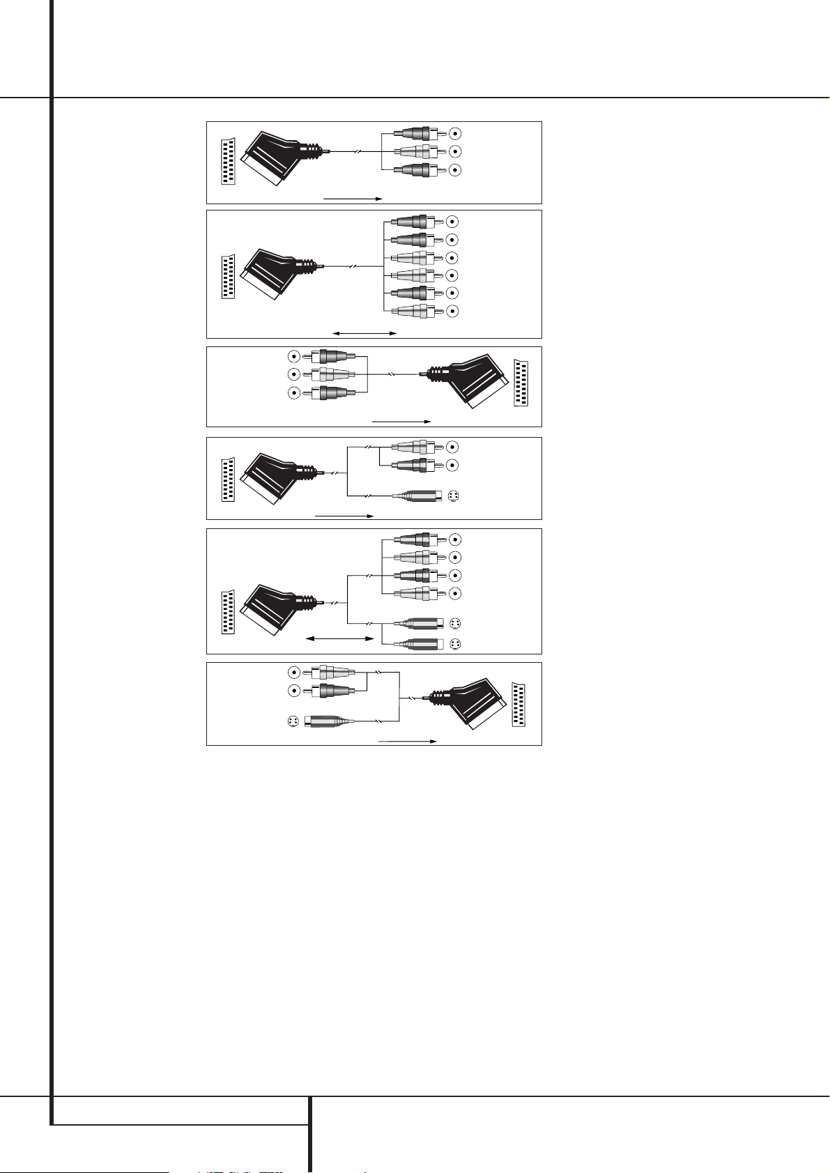
SCART A/V Connections
For the connections described above your video
device needs RCA (cinch) connectors or/and SVideo connectors for all Audio and Video signals:
Any normal video device (Not SVHS or High 
for only playback needs 3 RCA jacks,VCRs for
record and playback even 6 RCA jacks.Any
S-Video device (SVHS, High needs 2 RCA
(Audio) and 1 S-Video jack (Video), if it´s a playback unit, or 4 RCA (Audio In/Out) and
2 S-Video (Video In/Out) jacks, if it´s a recording
VCR.
Many european video devices are equipped with
RCA (Cinch) or S-Video jacks only partially, not
for all audio and video in/outputs needed as
described above, but with a so called Scart or
Euro-AV connector (almost rectangular jack with
21 pins, see drawings on next page).
In that case the following Scart to Cinch
adapters or cables are needed:
• Units for playback, such as satellite receivers,
camcorders, DVD or LD players, need an
adapter from Scart to 3 RCA plugs, see fig. 1
(normal video devices) or from Scart to 2
RCA+1 S-Video plugs, see fig. 4 (S-Video
devices).
• HiFi VCRs need an adapter from Scart to 6
RCA plugs, see fig. 2 (normal video), or from
Scart to 4 Audio+2S-Video jacks, see fig. 5
(S-Video VCR). Read carefully the instruction
attached to the adapter to find which of the
six plugs is used for the record signal to the
VCR (connect with the AVR´s Out jacks) and
for the playback signal from the VCR (connect
with the AVR´s In jacks). Do not misconnect
Audio and Video signals. Don´t hesitate to consult your dealer, if you are uncertain.
• If you use only normal video devices the TV
monitor needs an adapter from 3 RCA plugs
to Scart (fig. 3) only. If also S-Video devices are
used an adapter from 2 RCA+1S-Video plugs
to Scart is needed additionally (fig. 6), connected to the SCART input on your TV that is
provided for S-Video.
Note that only the video plugs (the «yellow»
cinch plug in fig. 3 and the S-Video plug in
fig. 6) must be connected to the TV Monitor
Output
, and the volume on the TV must be
reduced to minimum.
Important Note for Adapter Cables:
If the cinch connectors of the adapter you’ll use
are labeled, connect the Audio and Video ”In”
plugs with the corresponding Audio and Video
”In” jacks on the AVR (and with a VCR connect
the ”Out” plugs to the ”Out” jacks on the VCR).
Note that with some adapter types it may be
just turned around: If no signal is audible/ visible
when the VCR is playing connect the “Out”
plugs to the ”In” jacks on the AVR and turned
around. If the adapter plugs are not labeled in
that way, pay attention to the signal flow directions as shown in the diagrams above and in the
instruction attached to the adapter. If uncertain,
don’t hesitate to consult your dealer.
Important Notes for S-Video connections:
1. Only the S-Video In/Out of S-Video devices
must be connected to the AVR, NOT both,
normal video and S-Video In/Outputs (except the
TV, see item below).
When both connections are made, only the
S-Video signal will be viewed on the screen.
2. Like most common AV units the AVR does not
convert the Video signal to S-Video, only vice
versa. Thus both connections must be made from
the AVR to the TV if both, Video and S-Video
sources, are used, and the appropriate input on
the TV must be selected.
Video Equipment Connections
Video equipment is connected in the same manner as audio components.Again, the use of highquality interconnect cables is recommended to
preserve signal quality.To ensure best video
performance S-Video sources should be connected to the AVR 235 only with their S-Video In/
Outputs, not with their composite video
connectors too.
1. Connect a VCR’s audio and video Play/Out
jacks to the Video 1 or Video 2 In jacks
#%
on the rear panel. The Audio and Video
Record/In jacks on the VCR should be connected
to the Video 1 or Video 2 Out jacks
«
on the AVR.
2. Connect the analog audio and video outputs
of a satellite receiver, cable TV converter or television set or any other video source to the
Video 3
$
jacks.
IMPORTANT: If you are only using the television
as a display device (i.e., if you receive your television programs through a cable box or satellite
receiver), do not connect the TV’s outputs to the
Video 3 Audio/Video and S-Video Input
Jacks
$
, or to any other inputs on the AVR
235.
3. Connect the analog audio and video outputs
of a DVD or laser disc player to the DVD jacks
.
4. Connect the digital audio outputs of a CD,
MD or DVD player, satellite receiver, cable box or
HDTV converter to the appropriate Optical or
Coaxial Digital Inputs
!*Ó
.
5. Connect the Composite and S-Video (if
S-Video device is in use) Monitor Output
jacks on the receiver to the composite and
S-Video input of your television monitor or video
projector.
6. If your DVD player and monitor both have
component video connections, connect the component outputs of the DVD player to the DVD
Component Video Inputs
. Note that even
when component video connections are used
the audio connections must still be made to
either the analog DVD Audio Inputs
or any
of the Coaxial or Optical Digital Input jacks
!
.
7. If another component video device is available, connect it to the Video 2 Component
Video Input jacks
. The audio connections
for this device should be made to either the
Video 2 Input jacks
#
or any of the Coaxial
or Optical Digital Input jacks
!
.
8. If the component video inputs are used,
connect the Component Video Output
to
the component video inputs of your TV, projector
or display device.
14 INSTALLATION AND CONNECTIONS
Installation and Connections
Figure 1:
SCART/Cinch-Adapter for
playback;
signal flow:
SCART → Cinch
Black
Red
Blue
Yellow
Green
White
Figure 2:
SCART/Cinch-Adapter for
record and playback;
signal flow:
SCART ↔ Cinch
Figure 3:
Cinch/SCART-Adapter for
playback;
signal flow:
Cinch → SCART
Figure 4:
SCART/S-Video Adapter
for playback;
signal flow:
SCART → Cinch
Schwarz
Rot
Blau
Gelb
S-Video In
S-Video Out
Figure 5:
SCART/S-Video Adapter
for record and playback;
signal flow:
SCART ↔ Cinch
Figure 6:
SCART/S-Video Adapter
for playback;
signal flow:
Cinch → SCART
Black
Yellow
Red
Black
Red
Blue
1
Yellow
Green
1
White
Black
Yellow
Red
Red
Black
S-Video In
Red
Black
S-Video Out
Black
Red
Blue
1
Yellow
S-Video In
S-Video Out
1
Also other colours possible, e.g. brown and grey.
Important Note for the Use of
SCART-Cinch Adapters:
When video sources are connected to the TV
directly with a SCART cable, specific control
signals apart from Audio/Video signals will be
fed to the TV. These specific signals are:With all
video sources, the signal for automatic input
selection that switches the TV automatically to
the appropriate input as soon as the video
source is started. And with DVD players, the
signals automatically turning the TV to 4:3/16:9
format (with 16:9 TVs or with 4:3 TVs with
selectable 16:9 format) and turning the RGB
video decoder of the TV on or off, depending on
the DVD player´s setting. With any adapter cable,
these control signals will be lost and the
appropriate setting of the TV must be made
manually.
Note for RGB signal with SCART:
If you use a unit providing RGB signals on a
SCART output (as e.g. most DVD players do) and
you want to use that RGB signal, this SCART
output must be connected directly to your TV.
Although the AVR can switch three-way video
signals (like component signals Y/Pb/Pr), most
TVs need separate sync signals for RGB (also
with SCART) that cannot be switched and provided by the AVR.
RGB signals can be pathed through the AVR only
when no separate sync signal is needed (see last
”Video Connection Note” on page 13).
System and Power Connections
Main Room Remote Control Extension
If the receiver is placed behind a solid or smoked
glass cabinet door, the obstruction may prevent
the remote sensor from receiving commands. In
this event, the remote sensor of any Harman
Kardon or other compatible device, not covered
by the door, or an optional remote sensor may
be used. Connect the Remote IR Output of
that device or the output of the remote sensor to
the Remote IR Input jack
.
If other components are also prevented from
receiving remote commands, only one sensor is
needed. Simply use this unit’s sensor or a remote
eye by running a connection from the Remote
IR Output jack
to the Remote IR Input
jack on Harman Kardon or other compatible
equipment.
AC Power Connections
This unit is equipped with two accessory AC
outlets.They may be used to power accessory
devices, but they should not be used with
high-current draw equipment such as power
amplifiers.The total power draw to the
Unswitched Outlet
must not exceed
100 watts, that to the Switched Outlet
50 watts.
The Switched
outlet will receive power only
when the unit is on completely.This is recommended for devices that have no power switch
or a mechanical power switch that may be left in
the “ON” position.
NOTE: Many audio and video products go into a
Standby mode when they are used with
switched outlets, and cannot be fully turned on
using the outlet alone without a remote control
command.
The Unswitched
outlet will receive power
as long as the unit is plugged into a powered AC
outlet and the Main Power Switch
1
is on.
The AVR 235 draws significantly more current
than other household devices such as computers
that use removable power cords. For that reason, it is important that only the cord supplied
with the unit (or a direct replacement of identical capacity) be used.
Once the power cord is connected, you are
almost ready to enjoy the AVR 235’s incredible
power and fidelity!
Loading…
DIGITAL LOGIC 7 VID 1 DVD
CD
FMAM
TAPE
6 8 CH
VID 2
VID 3
VID 4
PRO LOGIC
3 STEREO DSP
5 7 CH. STEREO
SURR. OFF
AVR 235
AVR 235 AUDIO/VIDEO RECEIVER
OWNERS MANUAL
Power for the Digital Revolution.
AVR 235 OM 8/30/04 9:18 AM Page 1
AVR 235 AUDIO/VIDEO RECEIVER
3 Introduction 4 Safety Information 4 Unpacking 5 Front-Panel Controls 7 Rear-Panel Connections
10 Remote Control Functions 14 Installation and Connections 16 System Configuration 16 Speaker Placement 16 System Setup 17 Input Setup 18 Surround Setup 20 Speaker Setup 22 Delay Settings 23 Output Level Adjustment 23 Using EzSet 23 Manual Output Level Adjustment 25 Operation 25 Basic Operation 25 Source Selection 25 6-Channel/8-Channel Direct Input 25 Volume Control 26 Surround Mode Selection 26 Digital Audio Playback 27 Surround Mode Chart 29 Tuner Operation 30 Recording 30 Output Level Trim Adjustment 32 Advanced Features 32 Display Brightness 32 Turn-On Volume Level 32 Semi-OSD Settings 33 Full-OSD Time-Out Adjustment 33 Default Surround Mode 34 Programming the Remote 34 Programming Product Codes 34 Direct Code Entry 34 Auto Search Method 34 Code Readout 34 Macro Programming 35 Programmed Device Functions 36 Volume Punch-Through 36 Channel Control Punch-Through 36 Transport Control Punch-Through 36 Reassigning the VID4 Device Control Selector 37 Resetting the Remote Memory 38 Function List 40 Setup Code Tables 50 Troubleshooting Guide 50 Processor Reset 51 Technical Specifications 51 Trademark Acknowledgements 52 Index
Typographical Conventions In order to help you use this manual with the remote control, front-panel controls and rear-panel connections, certain conventions have been used.
EXAMPLE (bold type) indicates a specific remote control or front-panel button, or rear-panel connection jack
EXAMPLE (OCR type) indicates a message that is visible on-screen or on the front-panel information display
1 (number in a square) indicates a specific front-panel control
(number in a circle) indicates a rear-panel connection
a (number in an oval) indicates a button or indicator on the remote
(letter in an oval) indicates a button on the Zone II remote
AVR 235 OM 8/30/04 9:18 AM Page 2
INTRODUCTION
Thank you for choosing Harman Kardon! With the purchase of a Harman Kardon AVR 235, you are about to begin many years of listening enjoyment. Designed to provide all the excitement and detail of movie soundtracks and every nuance of musical selec- tions, the AVR 235 harnesses advanced technologies usually found only in higher priced receivers.
The AVR 235 has been engineered so that it is easy to take advantage of all the power of its digital tech- nology. However, to obtain the maximum enjoyment from your new receiver, we urge you to read this manual. A few minutes spent learning the functions of the various controls will enable you to take advantage of all the power the AVR 235 is able to deliver.
If you have any questions about this product, its instal- lation or its operation, please contact your retailer or custom installer. They are your best local sources of information.
Description and Features The AVR 235 is versatile and multifeatured, incorpo- rating a wide range of listening options. In addition to Dolby* Digital and DTS decoding for digital sources, a broad choice of Matrix surround-encoded or Stereo surround modes are available for use with sources such as CD, VCR, TV broadcasts and the AVR 235s own FM/AM tuner. Along with Dolby Digital EX, Dolby Pro Logic* II and IIx, DTS Neo:6, Dolby 3 Stereo, and Hall and Theater modes, the AVR 235 offers Harman Internationals exclusive Logic 7 processing in both 5.1 and 7.1 versions to create a wider, more enveloping field environment and more defined fly- overs and pans. Another exclusive is VMAx, which uses proprietary processing to create an open, spa- cious sound field even when only two front speakers are available. Dolby Virtual Speaker is also available to create an enveloping sound field when fewer than six speakers are used. The latest Dolby Headphone modes provide a much more open and realistic presentation for private headphone listening.
In addition to providing a wide range of listening options, the AVR 235 is easy to configure so that it provides the best results with your speakers and spe- cific listening-room environment. On-screen menus make it simple to enter settings for speaker configura- tions and bass management, and the EzSet remote measures a systems sound levels and automatically calibrates them for a perfectly balanced sound field presentation.
For the ultimate in flexibility, the AVR 235 features connections for five video devices, all with both com- posite and S-Video inputs. Two additional audio inputs are available, and six digital inputs make the AVR 235 capable of handling all the latest digital audio sources. For compatibility with the latest HDTV video sources and progressive scan DVD players, the AVR 235 also features two-input, wide-bandwidth, low-crosstalk component video switching.
The front panel offers coax and optical digital audio inputs for direct connection to digital recorders. Two video recording outputs, preamp-out and a color- coded eight-channel input, make the AVR 235 virtually future-proof, with everything needed to accommodate tomorrows new formats right onboard.
The AVR 235s powerful amplifier uses traditional Harman Kardon high-current design technologies to meet the wide dynamic range of any program selection.
Harman Kardon invented the high-fidelity receiver more than fifty years ago. With state-of-the-art circuitry and time-honored circuit designs, the AVR 235 is the perfect combination of the latest in digital audio tech- nology, a quiet yet powerful analog amplifier in an ele- gant, easy-to-use package.
For Canadian model
Modle pour les Canadien
A wide range of digital and matrix surround modes, including Dolby Digital, Dolby Digital EX, Dolby Pro Logic IIx, Dolby Virtual Speaker, Dolby Headphone, DTS, DTS-ES Discrete and Matrix and DTS Neo:6
Seven channels of high-current amplification
Harman Kardons exclusive Logic 7
processing, available with both 7.1 and 5.1 processing in a variety of modes, and two modes of VMAx
remote automatically sets output levels for optimal performance
High-bandwidth, HDTV-compatible compo- nent video switching
A/V Sync Delay to compensate for audio delay in digital video sources and displays
Discrete front-panel coaxial and optical digital inputs for easy connection to portable digital devices and video game consoles
Extensive bass-management options, includ- ing three separate crossover groupings
On-screen menu and display system
TM
Cet appareil numrique de la classe B est conforme la norme NMB-003 du Canada. Sur les modles dont la fiche est polarisee: ATTENTION: Pour viter les chocs lectriques, introduire la lame la plus large de la fiche dans la borne correspondante de la prise et pousser jusquau fond.
This class B digital apparatus complies with Canadian ICES-003. For models having a power cord with a polarized plug: CAUTION: To prevent electric shock, match wide blade of plug to wide slot, fully insert.
INTRODUCTION 3
CAUTION RISK OF ELECTRIC SHOCK
DO NOT OPEN
CAUTION: To prevent electric shock, do not use this (polarized)
plug with an extension cord, receptacle or other outlet
unless the blades can be fully inserted to
prevent blade exposure.
The lightning flash with arrowhead symbol, within an equilateral triangle, is intended to alert the user to the presence of uninsulated dangerous voltage within the products
enclosure that may be of sufficient magnitude to constitute a risk of electric shock to persons.
The exclamation point within an equilateral triangle is intended to alert the user to the presence of important operating and maintenance (servicing) instructions in the
literature accompanying the appliance.
AVR 235 OM 8/30/04 9:18 AM Page 3
SAFETY INFORMATION
Important Safety Information
Verify Line Voltage Before Use Your AVR 235 has been designed for use with 120-volt AC current. Connection to a line voltage other than that for which it is intended can create a safety and fire hazard and may damage the unit.
If you have any questions about the voltage requirements for your specific model, or about the line voltage in your area, contact your selling dealer before plugging the unit into a wall outlet.
Do Not Use Extension Cords To avoid safety hazards, use only the power cord attached to your unit. We do not recommend that extension cords be used with this product. As with all electrical devices, do not run power cords under rugs or carpets or place heavy objects on them. Damaged power cords should be replaced immediately by an authorized service center with a cord meeting factory specifications.
Handle the AC Power Cord Gently When disconnecting the power cord from an AC out- let, always pull the plug; never pull the cord. If you do not intend to use the unit for any considerable length of time, disconnect the plug from the AC outlet.
Do Not Open the Cabinet There are no user-serviceable components inside this product. Opening the cabinet may present a shock hazard, and any modification to the product will void your guarantee. If water or any metal object such as a paper clip, wire or a staple accidentally falls inside the unit, disconnect it from the AC power source immedi- ately, and consult an authorized service center.
CATV or Antenna Grounding If an outside antenna or cable system is connected to this product, be certain that it is grounded so as to provide some protection against voltage surges and static charges. Section 810 of the National Electrical Code, ANSI/NFPA No. 70-1984, provides information with respect to proper grounding of the mast and supporting structure, grounding of the lead-in wire to an antenna discharge unit, size of grounding conductors, location of antenna discharge unit, connection to grounding electrodes and requirements of the grounding electrode.
NOTE TO CATV SYSTEM INSTALLER: This reminder is provided to call the CATV (Cable TV) system installers attention to article 820-40 of the NEC which provides guidelines for proper grounding and, in particular, specifies that the cable ground shall be connected to the grounding system of the building, as close to the point of cable entry as possible.
Installation Location To ensure proper operation and to avoid the poten-
tial for safety hazards, place the unit on a firm and level surface. When placing the unit on a shelf, be certain that the shelf and any mounting hardware can support the weight of the product.
Make certain that proper space is provided both above and below the unit for ventilation. If this product will be installed in a cabinet or other enclosed area, make certain that there is sufficient air movement within the cabinet. Under some cir- cumstances a fan may be required.
Do not place the unit directly on a carpeted surface.
Avoid installation in extremely hot or cold locations, or in an area that is exposed to direct sunlight or heating equipment.
Avoid moist or humid locations.
Do not obstruct the ventilation slots on the top of the unit, or place objects directly over them.
Due to the weight of the AVR 235 and the heat generated by the amplifiers, there is the remote possibility that the rubber padding on the bottom of the units feet may leave marks on certain wood or veneer materials. Use caution when placing the unit on soft woods or other materials that may be damaged by heat or heavy objects.
Cleaning When the unit gets dirty, wipe it with a clean, soft, dry cloth. If necessary, and only after unplugging the power cord, wipe it with a soft cloth dampened with mild soapy water, then a fresh cloth with clean water. Wipe dry immediately with a dry cloth. NEVER use benzene, aerosol cleaners, thinner, alcohol or any other volatile cleaning agent. Do not use abrasive cleaners, as they may damage the finish of metal parts. Avoid spraying insecticide near the unit.
Moving the Unit Before moving the unit, be certain to disconnect any interconnection cords with other components, and make certain that you disconnect the unit from the AC outlet.
Important Information for the User This equipment has been tested and found to comply with the limits for a Class-B digital device, pursuant to Part 15 of the FCC Rules. The limits are designed to provide reasonable protection against harmful interfer- ence in a residential installation. This equipment gener- ates, uses and can radiate radio-frequency energy and, if not installed and used in accordance with the instructions, may cause harmful interference to radio communication. However, there is no guarantee that harmful interference will not occur in a particular instal-
lation. If this equipment does cause harmful interfer- ence to radio or television reception, which can be determined by turning the equipment off and on, the user is encouraged to try to correct the interference by one or more of the following measures:
Reorient or relocate the receiving antenna.
Increase the separation between the equipment and receiver.
Connect the equipment into an outlet on a circuit different from that to which the receiver is connected.
Consult the dealer or an experienced radio/TV technician for help.
This device complies with Part 15 of the FCC Rules. Operation is subject to the following two conditions: (1) this device may not cause harmful interference, and (2) this device must accept interference received, including interference that may cause undesired operation.
NOTE: Changes or modifications may cause this unit to fail to comply with Part 15 of the FCC Rules and may void the users authority to operate the equipment.
Unpacking
The carton and shipping materials used to protect your new receiver during shipment were specially designed to cushion it from shock and vibration. We suggest that you save the carton and packing materials for use in shipping if you move, or should the unit ever need repair.
To minimize the size of the carton in storage, you may wish to flatten it. This is done by carefully slitting the tape seams on the bottom and collapsing the carton. Other cardboard inserts may be stored in the same manner. Packing materials that cannot be collapsed should be saved along with the carton in a plastic bag.
If you do not wish to save the packaging materials, please note that the carton and other sections of the shipping protection are recyclable. Please respect the environment and discard those materials at a local recycling center.
it is important that you remove the protective plastic film from the front-panel lens. Leaving the film in place will affect the performance of your remote control.
4 SAFETY INFORMATION
AVR 235 OM 8/30/04 9:18 AM Page 4
FRONT-PANEL CONTROLS
1 Main Power Switch: Press this button to apply power to the AVR 235. When the switch is pressed in, the unit is in a Standby mode, as indicated by the amber Power Indicator 2 above the Standby/On Switch 3. This button MUST be pressed in to operate the unit. To turn the unit off and prevent the use of the remote control, this switch should be pressed until it pops out from the front panel and the word OFF is seen at the top of the switch.
NOTE: This switch is normally left in the ON position.
2 Power Indicator: This LED lights amber when the unit is in the Standby mode to signal that the AVR is ready to be turned on. When the unit is in operation, the indicator is blue.
3 Standby/On Switch: When the Main Power Switch 1 is ON, press this button to turn on the
AVR 235; press it again to turn the unit off. The Power Indicator 3 turns blue when the unit is on.
4 Headphone Jack: This jack may be used to listen to the AVR 235s output through a pair of headphones. The speakers will automatically be turned off when the headphone jack is in use.
5 Tone Mode: Pressing this button enables or dis- ables the Bass and Treble tone controls. When the but- ton is pressed so that TONE IN appears in the Lower Display Line , the Bass and Treble controls may be used to adjust the output signals. When the button is pressed once or twice so that the words TONE OUT appear in the Lower Display Line , the output signal will be flat, no matter how the actual Bass and Treble Controls are adjusted.
6 Speaker Select Button: Press this button to begin the process of configuring the unit to match the type of speakers used in your listening room. (See pages 16 and 2022 for more information on speaker setup and configuration.)
7 Surround Mode Group Selector: Press this but- ton to select the top-level group of surround modes. Each press of the button will select the current or last used mode in each of the surround mode groups (e.g., Dolby, DTS, DTS Neo:6, Logic 7, DSP, Stereo). When the button is pressed so that the name of the desired surround mode group appears in the on- screen display and in the Lower Display Line , press the Surround Mode Selector 8 to cycle through the individual modes available. For example, press this button to select Dolby modes, and then press the Surround Mode Selector 8 to choose from the various mode options.
1 Main Power Switch 2 Power Indicator 3 Standby/On Switch 4 Headphone Jack 5 Tone Mode 6 Speaker Selector 7 Surround Mode Group Selector 8 Surround Mode Selector 9 Tuning Selector ) / Buttons ! Tuner Band Selector
@ Set Button # Digital Input Selector $ Preset Stations Selector % Delay Adjust Selector ^ Input Source Selector & Tuner Mode Selector * Optical 3 Digital Audio Input ( Coaxial 3 Digital Audio Input Video 4 Video Input Jacks Video 4 Audio Input Jacks Bass Control
Balance Control Treble Control Channel Adjust Selector Volume Control Input Indicators Speaker/Channel Input Indicators Upper Display Line Lower Display Line Surround Mode Indicators Remote Sensor Window
1
2 6
7 #
(
*
8 )
!
@)
&%3
4
5 9
$ ^
DIGITAL LOGIC 7 VID 1 DVD
CD
FMAM
TAPE
6 8 CH
VID 2
VID 3
VID 4
PRO LOGIC
3 STEREO DSP
5 7 CH. STEREO
SURR. OFF
AVR 235
FRONT-PANEL CONTROLS 5
NOTE: To make it easier to follow the instructions that refer to this illustration, a larger copy may be downloaded from the Product Support section for this product at www.harmankardon.com.
AVR 235 OM 8/30/04 9:18 AM Page 5
8 Surround Mode Selector: Press this button to select from among the available surround mode options for the mode group selected. The specific modes will vary based on the number of speakers available, the mode group and if the input source is digital or analog. For example, press the Surround Mode Group Selector 7 to select a mode grouping such as Dolby or Logic 7, and then press this button to see the specific mode choices available. For more information on mode selection, see page 26.
9 Tuning Selector: Press the left side of the button to tune lower-frequency stations and the right side of the button to tune higher-frequency stations. When the tuner is in the Manual mode, each tap will increase or decrease the frequency by one increment. When the tuner receives a strong enough signal for adequate reception, MANUAL TUNED will appear in the on-screen display and the Lower Display Line . When the tuner is in the Auto mode, press the button once, and the tuner will scan for a station with accept- able signal strength. When the next station with a strong signal is tuned, the scan will stop and the on- screen display and the Lower Display Line
will indicate AUTO TUNED. When an FM Stereo station is tuned, the display will read AUTO ST TUNED.
To switch back and forth between the Auto and Manual tuning modes, press the Tuner Mode Selector &.
) / Buttons: When configuring the AVR 235s settings, use these buttons to select from the available choices.
! Tuner Band Selector: Press this button to turn the AVR 235 on and to select the Tuner as the input source. Press it again to switch between the AM and FM frequency bands. (See page 29 for more informa- tion on the tuner.)
@ Set Button: When making choices during the setup and configuration process, press this button to enter the desired setting into the AVR 235s memory.
# Digital Input Selector: Press this button to select one of the digital inputs or the analog input for any source. (See pages 2629 for more information on digital audio.)
$ Preset Stations Selector: Press this button to scroll up or down through the list of stations that have been entered into the preset memory. (See page 30 for more information on tuner presets.)
% Delay Adjust Selector: Press this button to begin the steps required to enter delay settings. (See page 22 for more information on delay times.)
^ Input Source Selector: Press this button to change the input by scrolling up or down through the list of Input Indicators .
& Tuner Mode Selector: Press this button to select Auto or Manual tuning. When the button is pressed so that AUTO appears in the Lower Display Line , the tuner will search for the next station with an accept- able signal when the Tuning Selector 9u
is pressed. When the button is pressed so that MANUAL appears in the Lower Display Line , each press of the Tuning Selector 9u will in- crease the frequency. This button may also be used to switch between Stereo and Mono modes for FM radio reception. When weak reception is encountered, press the button so that MANUAL appears in the Lower Display Line and the on-screen display to switch to Mono reception. Press it again to switch back to Stereo mode. (See page 29 for more information on using the tuner.)
* Optical 3 Digital Audio Input: Connect the optical digital audio output of an audio or video product to this jack. When the input is not in use, be certain to keep the plastic cap installed to avoid dust contamination that might degrade future performance.
( Coaxial 3 Digital Audio Input: This jack is used for connection to the output of portable audio devices, video game consoles or other products that have a coax digital audio jack.
Video 4 Video Input Jacks: These jacks may be used for temporary connection to the composite or S-Video output of video games, camcorders or other portable video products. You may make a connec- tion to either jack at any time, but not to both simultaneously.
Video 4 Audio Input Jacks: These audio jacks may be used for temporary connection to video games or portable audio/video products such as cam- corders and portable audio players.
Bass Control: Turn this control to modify the low- frequency output of the left/right channels by as much as 10dB.
Balance Control: Turn this control to change the relative volume for the front left/right channels.
NOTE: For proper operation of the surround modes, this control should be at the midpoint or 12 oclock position.
Treble Control: Turn this control to modify the high- frequency output of the left/right channels by as much as 10dB.
Channel Adjust Selector: Press this button to begin the process of trimming the channel output lev- els using an external audio source. (For more informa- tion on output level trim adjustment, see page 30.)
Volume Control: Turn this knob clockwise to increase the volume, counterclockwise to decrease the volume. If the AVR 235 is muted, adjusting the Volume Control will automatically release the unit from the silenced condition.
Input Indicators: The current selected source will appear as one of these indicators. Note that when the unit is turned on, the entire list of available sources will light briefly, and then revert to normal operation with only the active source indicator illuminated.
Speaker/Channel Input Indicators: These indi- cators are multipurpose, indicating both the speaker type selected for each channel and the incoming data- signal configuration. The left, center, right, surround and surround back speaker indicators are composed of three boxes, while the subwoofer is a single box. The center box lights when a small speaker is selected, and the two outer boxes light when large speakers are selected. When none of the boxes are lit for the center, surround or subwoofer channels, no speaker has been assigned that position. (See page 19 for more informa- tion on configuring speakers.) The letters inside each box display the active input channels. For standard ana- log inputs, only the L and R will light, indicating a stereo input. For a digital source, the indicators will light to dis- play the channels being received at the digital input. When the letters flash, the digital input has been inter- rupted. (See page 29 for more information on the Channel Indicators.)
Upper Display Line: Depending on the units sta- tus, a variety of messages will appear here. In normal operation, this line will show the current input source and which analog or digital input is in use. When the tuner is the input, this line will identify the station as AM or FM and show the frequency and preset number, if any.
Lower Display Line: Depending on the units sta- tus, a variety of messages will appear here. In normal operation, the current surround mode will show here.
Surround Mode Indicators: The current selected surround mode will appear as one of these indicators. Note that when the unit is turned on, the entire list of available modes will light briefly, and then revert to normal operation with only the active mode indicator illuminated.
Remote Sensor Window: The sensor behind this window receives infrared signals from the remote control. Aim the remote at this area and do not block or cover it.
38
FRONT-PANEL CONTROLS
6 FRONT-PANEL CONTROLS
AVR 235 OM 8/30/04 9:18 AM Page 6
REAR-PANEL CONNECTIONS 7
d
g
j
k i a
37 35
32
fh31
38 36 34
33
e c
b
REAR-PANEL CONNECTIONS
CD Audio Inputs Tape Outputs Remote IR Input Remote IR Output Preamp Outputs Subwoofer Output Front Speaker Outputs Surround Back Speaker Outputs Surround Speaker Outputs Center Speaker Output Component Video Monitor Outputs Video 2 Component Video Inputs DVD Component Video Inputs
AC Power Cord Switched AC Accessory Outlet Unswitched AC Accessory Outlet Optical Digital Audio Output Coaxial Digital Audio Output S-Video Monitor Output a Coaxial Digital Audio Inputs b DVD S-Video Input c Video 1 S-Video Input d Optical Digital Audio Inputs e Video 1 S-Video Output f Video 2 S-Video Input g 6/8-Channel Direct Inputs
h Video 2 S-Video Output i Video 3 S-Video Input j Video Monitor Output k DVD Audio/Video Inputs
Video 1 Audio/Video Inputs Video 1 Audio/Video Outputs Video 2 Audio/Video Inputs Video 2 Audio/Video Outputs Video 3 Audio/Video Inputs Tape Inputs AM Antenna Terminals FM Antenna Jack38
37
36
35
34
33
32
31
NOTE: To assist in making the correct connections for multichannel input, output and speaker connections, all connection jacks and terminals are color-coded in conformance with the CEA standards as follows:
Front Left: White Front Right: Red Center: Green
Surround Left: Blue Surround Right: Gray Surround Back Left: Brown Surround Back Right: Tan Subwoofer: Purple Coaxial Digital Audio: Orange Composite Video: Yellow
Component Video Y: Green Component Video Pr: Red Component Video Pb: Blue
CD Audio Inputs: Connect these jacks to the analog audio output of a compact disc player or changer.
Tape Outputs: Connect these jacks to the RECORD/INPUT jacks of an audio recorder.
Remote IR Input: If the AVR 235s front-panel
IR sensor is blocked due to cabinet doors or other obstructions, an external IR sensor may be used. Connect the output of the sensor to this jack.
Remote IR Output: This connection permits the IR sensor in the receiver to serve other remote con- trolled devices. Connect this jack to the IR IN jack on Harman Kardon (or other compatible) equipment.
Preamp Outputs: Connect these jacks to an optional, external power amplifier for applications for which higher power is desired.
Subwoofer Output: Connect this jack to the line- level input of a powered subwoofer. If an external sub- woofer amplifier is used, connect this jack to the sub- woofer amplifier input.
NOTE: To make it easier to follow the instructions that refer to this illustration, a larger copy may be downloaded from the Product Support section for this product at www.harmankardon.com.
AVR 235 OM 8/30/04 9:18 AM Page 7
8 REAR-PANEL CONNECTIONS
REAR-PANEL CONNECTIONS
Front Speaker Outputs: Connect these outputs to the matching + or terminals on your left and right speakers. When making speaker connections, always make certain to maintain correct polarity by connecting the color-coded (white for front left and red for front right) (+) terminals on the AVR 235 to the red (+) terminals on the speakers and the black () terminals on the AVR 235 to the black () terminals on the speakers. See page 14 for more information on speaker polarity.
Surround Back Speaker Outputs: These speaker terminals are used to power the surround back left/surround back right speakers in a 7.1 chan- nel system. The brown and black terminals are the surround back left channel positive (+) and negative () connections and the tan and black terminals are the surround back right positive (+) and negative () terminals.
Surround Speaker Outputs: Connect these out- puts to the matching + and terminals on your sur- round channel speakers. In conformance with the CEA color-code specification, the blue terminal is the posi- tive, or +, terminal that should be connected to the red (+) terminal on the Surround Left speaker with older color-coding, while the gray terminal should be connected to the red (+) terminal on the Surround Right speaker with the older color-coding. Connect the black () terminal on the AVR to the matching black negative () terminals for each surround speaker. (See page 14 for more information on speaker polarity.)
Center Speaker Output: Connect these outputs to the matching + and terminals on your center channel speaker. In conformance with the CEA color- code specification, the green terminal is the positive, or +, terminal that should be connected to the red (+) terminal on speakers with the older color-coding. Connect the black () terminal on the AVR to the black () terminal on your speaker. (See page 14 for more information on speaker polarity.)
Component Video Monitor Outputs: Connect these outputs to the component video inputs of a video projector or monitor. When a source connected to one of the Component Video Inputs is selected, the signal will be sent to these jacks.
Video 2 Component Video Inputs: Connect the Y/Pr/Pb component video outputs of an HDTV set-top converter, satellite receiver or other video source device with component video outputs to these jacks.
DVD Component Video Inputs: Connect the Y/Pr/Pb component video outputs of a DVD player to these jacks.
AC Power Cord: Connect the AC power cord to a non-switched AC wall outlet.
Switched AC Accessory Outlet: This outlet may be used to power any device you wish to have turned on when the AVR 235 is turned on.
Unswitched AC Accessory Outlet: This outlet may be used to power any AC device. The power will remain on at this outlet, regardless of whether the AVR 235 is on or off.
NOTE: The total power consumption of all devices connected to the accessory outlets should not exceed 100 watts.
Optical Digital Audio Output: Connect this jack to the optical digital input connector on a CD-R/RW, MiniDisc or other digital recorder.
Coaxial Digital Audio Output: Connect this jack to the coaxial digital input of a CD-R/RW, MiniDisc or other digital recorder.
S-Video Monitor Output: When your television or other video display is equipped with an S-Video input and you are using at least one source with S-Video capability, connect this jack to the S-Video input on the display.
a Coaxial Digital Audio Inputs: Connect the coax digital output from a DVD player, HDTV receiver, LD player or CD player to these jacks. The signal may be a Dolby Digital signal, DTS signal or a standard PCM digital source. Do not connect the RF digital output of an LD player to these jacks.
b DVD S-Video Input: Connect the S-Video output of a DVD player or other video source to this jack.
c Video 1 S-Video Input: If the product connected to the Video 1 Audio Inputs has S-Video capability, connect this jack to the PLAY/OUT S-Video jack on that unit and then make certain that the S-Video Monitor Output is connected as described above.
d Optical Digital Audio Inputs: Connect the optical digital output from a DVD player, HDTV receiver, LD player or CD player to these jacks. The signal may be a Dolby Digital signal, a DTS signal or a standard PCM digital source.
e Video 1 S-Video Output: If the product connected to the Video 1 Audio Outputs has S-Video capability, connect this jack to the REC/IN S-Video jack on that unit.
f Video 2 S-Video Input: If the product connected to the Video 2 Audio Inputs has S-Video capability, connect this jack to the PLAY/OUT S-Video jack on that unit and then make certain that the S-Video Monitor Output is connected, as described above.
g 6/8-Channel Direct Inputs: These jacks are used for connection to source devices such as DVD- Audio or SACD players with discrete analog outputs. Depending on the source device in use, all eight jacks may be used, though in many cases only connections to the front left/right, center, surround left/right and LFE (subwoofer input) jacks will be used for standard 5.1 audio signals.
h Video 2 S-Video Output: If the product connected to the Video 2 Audio Outputs has S-Video capability, connect this jack to the REC/IN S-Video jack on that unit.
i Video 3 S-Video Input: If the product connected to the Video 3 Audio Inputs has S-Video capability, connect this jack to the PLAY/OUT S-Video jack on that unit and then make certain that the S-Video Monitor Output is connected as described above.
j Video Monitor Output: Connect this jack to the composite video input of a TV monitor or video projec- tor to view the on-screen menus and the output of a standard video source.
k DVD Audio/Video Inputs: Connect the composite video and L/R analog audio output jacks of a DVD player or other video source to these jacks.
Video 1 Audio/Video Inputs: Connect the com- posite video and L/R analog audio PLAY/OUT jacks of a VCR or other video source to these jacks.
Video 1 Audio/Video Outputs: Connect the composite video and L/R analog audio REC/IN jacks of a VCR or other video recording device such as a DVD recorder or PVR to these jacks.
Video 2 Audio/Video Inputs: Connect the com- posite video and L/R analog audio PLAY/OUT jacks of a VCR or other video source to these jacks.
Video 2 Audio/Video Outputs: Connect the composite video and L/R analog audio REC/IN jacks of a VCR or other video recording device such as a DVD recorder or PVR to these jacks.
Video 3 Audio/Video Inputs: Connect the com- posite video and L/R analog audio PLAY/OUT jacks of a VCR or other video source to these jacks.
35
34
33
32
31
35
34
33
32
31
AVR 235 OM 8/30/04 9:18 AM Page 8
REAR-PANEL CONNECTIONS 9
REAR-PANEL CONNECTIONS
Tape Inputs: Connect these jacks to the PLAY/OUT jacks of an audio recorder.
AM Antenna Terminals: Connect the AM loop antenna supplied with the receiver to these terminals. If an external AM antenna is used, make connections to the AM and GND terminals, in accordance with the instructions supplied with the antenna.
FM Antenna Jack: Connect the supplied indoor (or an optional external) FM antenna to this terminal.
NOTE ON VIDEO CONNECTIONS: When connecting a source device such as a VCR, DVD player, cable or satellite set-top box or video game to the AVR, use either a composite or S-Video connection for each input, but not both.
38
37
36
AVR 235 OM 8/30/04 9:18 AM Page 9
REMOTE CONTROL FUNCTIONS
10 REMOTE CONTROL FUNCTIONS
a Power Off Button b IR Transmitter Window c Program/SPL Indicator d Power On Button e Input Selectors f AVR Selector g AM/FM Tuner Select h Dim Button i Test Button j Sleep Button k DSP Surround Mode Selector l Night Mode m Channel Select Button n / Buttons o / Buttons p Set Button q Digital Select r Numeric Keys s Tuner Mode t Direct Button u Tuning Up/Down v OSD Button w Dolby Mode Selector x DTS Digital Mode Selector y Logic 7 Mode Select Button z Skip Up/Down Buttons ` Transport Controls Stereo Mode Select Button DTS Neo:6 Mode Select Macro Buttons Disc Skip Button Preset Up/Down Clear Button Memory Button Delay/Prev. Ch. Speaker Select Spare Button Volume Up/Down TV/Video Selector SPL Selector 6-Channel/8-Channel Direct Input Mute EzSet Sensor Microphone
NOTE: The function names shown here are each buttons feature
when used with the AVR 235. Most buttons have additional functions when used with other devices. See pages 3839 for a list of these functions.
To make it easier to follow the instructions that refer to this illustration, a larger copy may be downloaded from the Product Support section for this product at www.harmankardon.com.
s
abc
d e
f
g h
j
n
n
p oo
q
r
t
v
`
32
30
29
28
36
37
38
39 40
z
x
35
POWER
MUTE
AVR DVD
AM/FM
CD TAPE
VID 2 VCR TVCBL/SAT
6/8 CH SPL
VID 1 VID 3 VID 4
OFFON
SLEEP T/V
SURR. CH. VOL.
GUID
E
CH.
EXIT DIGITAL
MENU
SPKR
PREV.CH.DELA Y
SET
1 2 3 4
765
9 0TUN-M MEM
M2 M3 M4
D.SKIP
M1
DIRECT
OSD TUNING
DOLBY SUR DTS SUR DTS NEO:6
STEREOLOGIC 7
……..SKIP…….. UPDWN
PRESET
CLEAR
TEST
NIGHT
8
l
u
DIM
i
k
m
34 33
w
y
41
43
TM
31
42
AVR 235 OM 8/30/04 9:18 AM Page 10
REMOTE CONTROL FUNCTIONS
REMOTE CONTROL FUNCTIONS 11
IMPORTANT NOTE: The AVR 235s remote may be programmed to control up to eight devices, including the AVR 235. Before using the remote, it is important to remember to press the Input Selector Button e
that corresponds to the unit you wish to operate. In addition, the AVR 235s remote is shipped from the factory to operate the AVR 235 and most Harman Kardon CD or DVD players and cassette decks. The remote is also capable of operating a wide variety of other products using the control codes that are part of the remote. Before using the remote with other products, follow the instructions on pages 3536 to program the proper codes for the products in your system.
It is also important to remember that many of the but- tons on the remote take on different functions, depend- ing on the product selected using the Device Control Selectors. The descriptions shown here primarily detail the functions of the remote when it is used to operate the AVR 235. (See page 35 for information about alternate functions for the remotes buttons.)
a Power Off Button: Press this button to place the AVR 235 or a selected device in the Standby mode.
b IR Transmitter Window: Point this window towards the AVR 235 when pressing buttons on the remote to make certain that infrared commands are properly received.
c Program/SPL Indicator: This three-color indica- tor is used to guide you through the process of pro- gramming the remote, and it is also used as a level indicator when using the remotes EzSet capabilities. (See page 23 for more information on setting output levels, and see page 35 for information on program- ming the remote.)
d Power On Button: Press this button to turn on the power to a device selected by pressing one of the Input Selectors e.
e Input Selectors: Pressing one of these buttons will perform three actions at the same time. First, if the AVR 235 is not turned on, this will power up the unit. Next, it will select the source shown on the button as the input to the AVR 235. Finally, it will switch the remote control so that it controls the device selected. After pressing one of these buttons, you must press the AVR Selector Button f again to operate the AVR 235s functions with the remote.
f AVR Selector: Pressing this button will switch the remote so that it will operate the AVR 235s functions. If the AVR 235 is in the Standby mode, it will also turn the AVR 235 on.
g AM/FM Tuner Select: Press this button to select the AVR 235s tuner as the listening choice. Pressing this button when the tuner is already in use will select between the AM and FM bands.
h Dim Button: Press this button to activate the Dimmer function, which reduces the brightness of the front-panel display, or turns it off entirely. The first press of the button shows the default state, which is full bright- ness, by indicating VFDFULL in the Lower Display Line . Press the button again within five seconds to reduce the brightness by 50%, as indicated by VFDHALF showing in the Lower Display Line . Press the button again within five seconds and the main display will go completely dark. Note that this set- ting is temporary in that, regardless of any changes, the display will always return to full brightness when the AVR is turned on. In addition, the Power Indicator 2 will always remain at full brightness, regardless of the set- ting. This is to remind you that the AVR is still turned on.
i Test Button: Press this button to begin the sequence used to calibrate the AVR 235s output levels. (See page 23 for more information on calibrating the AVR 235.)
j Sleep Button: Press this button to place the unit in the Sleep mode. After the time shown in the display, the AVR 235 will automatically go into the Standby mode. Each press of the button changes the time until turn-off in the following order:
This button is also used to change channels on your TV when the TV is selected.
When the AVR 235 remote is being programmed with the codes to operate another device, this button is also used in the Auto Search process. (See page 35 for more information on programming the remote.)
k DSP Surround Mode Selector: Press this but- ton to cycle through the DSP, VMAx and Stereo sur- round modes such as Hall, Theater, VMAx Near and Far, and Surround Off. This button is also used to tune channels when the TV is selected using the device Input Selector e. When the AVR 235 remote is being programmed with the codes of another device, this button is also used in the Auto Search process. (See page 35 for more information on programming the remote.)
l Night Mode: Press this button to activate the Night mode. This mode is available in specially encoded digital sources, and it preserves dialogue (center channel) intelligibility at low volume levels.
m Channel Select Button: This button is used to start the process of setting the AVR 235s output levels to an external source. Once this button is pressed, use the / Buttons n to select the channel being adjusted, then press the Set Button p, followed by the /
Buttons n again, to change the level setting. (See page 30 for more information.)
n / Buttons: These multipurpose buttons are used to change or scroll through items in the on- screen menus, make configuration settings such as digital inputs or delay timing, or to select surround modes. When changing a setting, first press the button for the function or setting to be changed (e.g., press the DSP Surround Mode Selector k to select a sound field mode or the Digital Select Button q
to change a digital input) and then press one of these buttons to scroll through the list of options or to increase or decrease a setting. The sections in this manual describing the individual features and functions contain specific information on using these buttons for each application.
o / Buttons: These buttons are used to change the menu selection or setting during some of the setup procedures for the AVR 235.
p Set Button: This button is used to enter settings into the AVR 235s memory. It is also used in the setup procedures for delay time, speaker configuration and channel output level adjustment.
q Digital Select: Press this button to assign one of the digital inputs *(ad to a source. (See page 26 for more information on using digital inputs.)
r Numeric Keys: These buttons serve as a 10- button numeric keypad to enter tuner preset positions. They are also used to select channel numbers when TV, Cable or SAT has been selected on the remote, or to select track numbers on a CD, DVD or LD player, depending on how the remote has been programmed.
s Tuner Mode: Press this button when the tuner is in use to select between automatic tuning and manual tuning. When the button is pressed so that MANUAL appears in the Lower Display Line , pressing the Tuning Buttons u9 will move the frequency up or down in single-step increments. When the FM band is in use, pressing this button when a stations signal is weak will change to monaural recep- tion. (See page 29 for more information.)
90 min
80 min
70 min
60 min
50 min
40 min
30 min
20 min
10 min OFF
AVR 235 OM 8/30/04 9:18 AM Page 11
12 REMOTE CONTROL FUNCTIONS
REMOTE CONTROL FUNCTIONS
t Direct Button: Press this button when the tuner is in use to start the sequence for direct entry of a sta- tions frequency. After pressing the button, simply press the proper Numeric Keys r to select a sta-
AVR 235 specifications
The Harman-Kardon AVR 235 is a high-performance AV receiver that exemplifies the brand’s commitment to delivering high-fidelity sound and cutting-edge technology. Designed for home theater enthusiasts, it combines a sleek aesthetic with powerful audio performance, making it an appealing choice for those looking to elevate their cinematic experience.
One of the standout features of the AVR 235 is its 7.1-channel surround sound capability, allowing for a truly immersive audio experience. It can deliver up to 70 watts per channel, ensuring that every sound, from the softest whisper to the loudest explosion, is reproduced with clarity and power. The receiver supports various surround sound formats, including Dolby Digital, Dolby Pro Logic II, and DTS, providing users with a versatile listening experience tailored to any content.
The AVR 235 integrates several advanced technologies to improve sound quality. This includes Harman-Kardon’s proprietary «Logic 7» technology, which enhances stereo sources to provide a more expansive surround sound experience. Its advanced DSP (Digital Signal Processing) algorithms further optimize the audio signals, ensuring that the sound is not only powerful but also richly detailed and accurate.
Connectivity options abound with the AVR 235, facilitating a range of devices to be hooked up effortlessly. It features multiple HDMI inputs, component and composite video inputs, as well as analog and digital audio inputs. This extensive range of connections allows for seamless integration with Blu-ray players, gaming consoles, streaming devices, and more, making it a versatile hub for home entertainment.
The AVR 235 also places a strong emphasis on user-friendliness, boasting an intuitive on-screen display and a user-friendly remote control. The graphical user interface guides users through the setup process and offers various adjustments to accommodate different room acoustics and personal preferences.
Additionally, the AVR 235 supports multi-room audio configurations, enabling users to enjoy sound throughout the house. It features an integrated AM/FM tuner, allowing access to radio stations, and provides options for connecting to external audio sources.
In summary, the Harman-Kardon AVR 235 is a powerful and feature-rich AV receiver that delivers exceptional sound quality and versatility. Its advanced technologies, extensive connectivity options, and user-friendly design make it an excellent choice for anyone looking to enhance their home theater system and enjoy a superior audio experience. With the AVR 235, Harman-Kardon once again proves its prowess in the world of high-fidelity audio.
-
Page 1
A VR 235 Audio/ V ideo Receiver OWNER’S MANU AL Power for the Digital Revolution ®[…]
-
Page 2
2 T ABLE OF CONTENTS 3 Introduction 4 Safety Information 4 Unpacking 5 F ront P anel Controls 7 Rear P anel Connections 9 Main Remote Control Functions 12 Installation and Connections 12 Audio Connections 12 External Amplifier Connections 13 Video Connections 13 SCAR T A/V Connections 14 System and P ower Connections 15 Speak er Selection 15 Speak […]
-
Page 3
INTRODUCTION 3 Introduction Thank you for choosing Harman Kardon! With the purchase of a Harman Kardon A VR 235 you are about to begin many years of listening enjoyment. Designed to provide all the excitement and detail of movie soundtracks and every nuance of musical selections , the A VR 235 is truly a multichannel receiver for the new mil- lenni[…]
-
Page 4
4 SAFETY INFORMA TION Safety Information Important Safety Information V erify Line V oltage Before Use Y our A VR has been designed for use with 220- 240-V olt AC current. Connection to a line voltage other than that for which it is intended can create a safety and fire hazard and may damage the unit. If you have any questions about the voltage req[…]
-
Page 5
FRONT P ANEL CONTROLS 5 1 Main P ower Switch: Press this button to apply power to the A VR. When the switch is pressed in, the unit is placed in a Standby mode , as indicated by the or ange LED 3 . T his button MUST be pressed in to operate the unit. T o turn the unit off completely and prevent the use of the remote control, this switch should be p[…]
-
Page 6
6 FRONT P ANEL CONTROLS Front P anel Controls 7 Selector Buttons: When you are establishing the A VR’ s configuration settings , use these buttons to select from the choices available , as shown in the Main Information Display ˜ . 8 T one Mode: Pressing this button enables or disables the Balance , Bass and T reble tone controls . When the butto[…]
-
Page 7
REAR P ANEL CONNECTIONS 7 Rear P anel Connections ! » # $ % AM Antenna FM Antenna T ape Inputs T ape Outputs Subwoofer Output DVD Audio Inputs CD Inputs Video 1 Audio Outputs Preamp Outputs 8-Channel Direct Inputs Digital Aud[…]
-
Page 8
8 REAR P ANEL CONNECTIONS Rear P anel Connections Video Monitor Outputs: Connect this jack to the composite and/or S-Video input of a TV monitor or video projector to view the on-screen menus and the output of any standard Video or S-Video source selected by the receiver’ s video switcher . DVD V ideo Inputs: Connect these jacks to the co[…]
-
Page 9
0 1 2 3 4 5 6 7 8 9 A B C D E F G H I J K L M N O P Q ! » # $ % & ‘ ( ) * + , — MAIN REMO TE CONTROL FUNCTIONS 9 Main Remote Control Functions P ower Off Button IR T ransmitter Window Program/SPL Indicator P ower On Button Input Selectors A VR Selector AM/FM T uner Select 6-Channel/8-Channel Direct Input T est Button Sleep[…]
-
Page 10
10 MAIN REMO TE CONTROL FUNCTIONS Main Remote Control Functions IMPORT ANT NO TE: The A VR 235’ s remote may be programmed to control up to seven devices , including the A VR. Before using the remote , it is important to remember to press the Input Selector button 4 that corresponds to the unit you wish to operate . In addition, the A VR’ s rem[…]
-
Page 11
MAIN REMO TE CONTROL FUNCTIONS 11 M Dolby Mode Selector: T his button is used to select one of the available Dolby Surround processing modes . Each press of this button will select one of the Dolby Pro Logic II modes , Dolby 3 Stereo or Dolby Digital. Note that the Dolby Digital mode is only available with a digital input selected and the other mod[…]
-
Page 12
12 INST ALLATION AND CONNECTIONS After unpacking the unit, and placing it on a solid surface capable of supporting its weight, you will need to mak e the connections to your audio and video equipment. Audio Equipment Connections We recommend that you use high-quality inter- connect cables when making connections to source equipment and recorders to[…]
-
Page 13
INST ALLATION AND CONNECTIONS 13 Installation and Connections 9. If you have a camcorder , video game or other audio/video device that is connected to the A VR on a temporary , rather than permanent basis , connect the audio , video and digital audio out- puts of that device to the Front P anel Inputs *ÓÔ . A device connected to the Video 4 jacks[…]
-
Page 14
14 INST ALLATION AND CONNECTIONS Installation and Connections Black Y ellow Red Figure 1: SCART/Cinch-Adapter for playback; signal flow: SCART → Cinch Black Red Blue Y ellow Green White Figure 2: SCART/Cinch-Adapter for record and playback; signal flow: SCART ↔ Cinch Black Y ellow Red Figure 3: Cinch/SCART -Adapter for playback; signal flow: Ci[…]
-
Page 15
INST ALLATION AND CONNECTIONS 15 Installation and Connections Speaker Selection No matter which type or brand of speak ers is used, the same model or brand of speak er should be used for the front-left, center and front-right speak ers. T his creates a seamless front soundstage and eliminates the possibility of distracting sonic disturbances that o[…]
-
Page 16
16 SY STEM CONFIGURATION System Configuration Once the speak ers have been placed in the room and connected, the remaining steps are to pro- gram the system configur ation memories. With the A VR two kind of memories are used, those associated individually with the input selected, e .g. surround modes , and others working global- ly for all inputs […]
-
Page 17
SY STEM CONFIGURATION 17 T o make this process as quick and as easy as pos- sible , we suggest that you use the full-OSD sys- tem with the on-screen menus , and step through each input. Input Setup T he first step in configuring the A VR is to select an input, i.e . to associate an analog or digital input with each input source in use , e .g. CD or[…]
-
Page 18
18 SY STEM CONFIGURATION System Configuration opposed to a movie from a DVD player , VCR or cable/satellite set top . If you wish to customize the speak er size individ- ually to each input, mak e certain that the cursor is on the BASS MGR line and press the ‹ / › Buttons E& so that INDEPENDENT appears in highlighted video . When this setti[…]
-
Page 19
SY STEM CONFIGURATION 19 T he choices available for the subwoofer position will depend on the settings for the other speak- ers , particularly the front left/right positions . If the front left/right speak ers are set to SMALL , the subwoofer will automatically be set to SUB , which is the “on” position. If the front left/right speak ers are se[…]
-
Page 20
20 SY STEM CONFIGURATION System Configuration As an example , in the Figure below , all speak ers are set for “large, ” and a subwoofer is set. Surround Setup Once the speak er setup has been completed, the next step for that input is to set the surround mode you wish to use with that input. Since sur- round modes are a matter of personal taste[…]
-
Page 21
SY STEM CONFIGURATION 21 System Configuration button D to access the AUDIO SETUP and press Set F to select the SURROUND SETUP menu. Press Set F to select the DOLBY menu (see fig. 7). Figure 7 T o adjust the Night mode setting, mak e certain that the ➞ cursor is on the NIGHT line of the DOLBY menu. Next, press ‹ / › Buttons E& to choose be[…]
-
Page 22
22 SY STEM CONFIGURATION System Configuration T he factory default setting is to have the sub- woofer turned off for this mode , but you may change that setting by following these steps: 1. Press the Speaker Button 6 ‘ . 2. Press the Set Button F @ to activate the configuration menu. 3. Press the ⁄ / ¤ Buttons D on the remote or the ‹ / ?[…]
-
Page 23
SY STEM CONFIGURATION 23 System Configuration When the delay settings are complete , press the ¤ Button D once so that the cursor is next to the BACK T O MASTER MENU line and press the Set Button p to return to the MASTER menu. Output Level Adjustment Output level adjustment is a k ey part of the configuration of any surround-sound product. It is […]
-
Page 24
24 SY STEM CONFIGURATION System Configuration Manual Output Level Adjustment Output levels may also be adjusted manually , either to set them to a specific level with an SPL meter , or to mak e fine tuning adjustments to the levels obtained using the EzSet remote . Manual output level adjustment is most easily done through the CHANNEL ADJUST menu ([…]
-
Page 25
SY STEM CONFIGURATION 25 System Configuration Once the settings outlined on the previous pages have been made , the A VR is ready for operation. While there are some additional settings to be made , these are best done after you have had an opportunity to listen to a variety of sources and different kinds of program material. T hese advanced settin[…]
-
Page 26
26 OPERA TION Operation Surround Mode Chart MODE FEA TURES DELA Y TIME RANGE DOLBY DIGIT AL Available only with digital input sources encoded with Dolby Digital data. It provides Center: 0 — 30ft / 9m up to five separate main audio channels and a special dedicated Low F requency Effects Initial Setting: 12ft / 3.6m channel. Surround: 0 — 30ft / 9m […]
-
Page 27
OPERA TION 27 Operation Surround Mode Chart MODE FEA TURES DELA Y TIME RANGE DTS Neo:6 Cinema T hese two modes are available when any analog source is playing to create a six-channel Delay time not adjustable DTS Neo:6 Music surround presentation from conventional Matrix-encoded and traditional Stereo sources . Select the Cinema version of Neo:6 wh[…]
-
Page 28
28 OPERA TION Operation Basic Operation Once you have completed the setup and configu- ration of the A VR, it is simple to operate and enjoy . T he following instructions should be followed for you to maximize your enjoyment of your new receiver: T urning the A VR On or Off • When using the AVR for the first time , you must press the Main P ower […]
-
Page 29
OPERA TION 29 Operation Controls and Use of Headphones • Adjust the volume to a comfortable level using the front panel V olume Control ı or remote V olume Up/Down ) buttons . • T o temporarily silence all speak er outputs press the Mute button ( . This will interrupt the out- put to all speak ers and the headphone jack, but it will not affect[…]
-
Page 30
30 OPERA TION Operation T o listen to a program in traditional two-channel stereo , using the front left and front right speak ers only (plus the subwoofer , if installed and configured), press the Stereo Button 5 until SURR OFF appears in the Main Information Display ˜ . Digital Audio Playback Digital audio is a major advancement over older a[…]
-
Page 31
OPERA TION 31 Operation Surround Mode T ypes F or Dolby Digital and DTS sources, a three digit indication will appear , showing the number of channels present in the data. An example of this type of display is 3/2/.1. T he first number indicates how many discrete front channel signals are present. • A 3 tells you that separate front left, center […]
-
Page 32
32 OPERA TION Operation Important Note: When a digital surround source (Dolby Digital, DTS) is played, the letters SBL/SBR for the Surround Back channels will appear only when a DTS ES DISCRETE 6.1 source is played. Then this surround mode will be indi- cated in the front display and on-screen display . With all other recordings the icons for the s[…]
-
Page 33
OPERA TION 33 Advanced Featur es Operation Repeat the procedure as needed until all chan- nels requiring adjustment have been set. When all adjustments have been made and no further adjustments are made for five seconds , the A VR will return to normal operation. If you are using a disc with noise test signals or an external signal generator as the[…]
-
Page 34
34 INTRODUCTION / ADV ANCED FEATURES Display Brightness T he A VR’ s front panel Main Information Display ˜ is set at a default brightness level that is sufficient for viewing in a normally lit room. However , in some home theater installa- tions , you may wish to occasionally lower the brightness of the display , or turn it off completely . T o[…]
-
Page 35
TUNER OPERA TION 35 T uner Operation the ⁄ / ¤ Buttons D as needed. Next, press the ‹ / › buttons E& until the desired time is displayed in seconds . Note that unlik e most of the other options in this menu, this is a perma- nent setting change , and the time-out entry will remain in effect until it is changed, even when the unit is turn[…]
-
Page 36
36 TUNER OPERA TION RDS Operation T he A VR 235 is equipped with RDS (Radio Data System), which brings a wide range of informa- tion to FM radio . Now in use in many countries , RDS is a system for transmitting station call signs or network information, a description of station program type , text messages about the station or specifics of a musica[…]
-
Page 37
PROGRAMMING THE REMO TE 37 Progr amming the Remote T he A VR 235 is equipped with a powerful remote control that will control not only the receiver’ s functions , but also most popular br ands of audio and video equipment, including CD players , TV sets , cable boxes , VCRs, satellite receivers and other home-theater equipment. Once the A VR’ s[…]
-
Page 38
38 PROGRAMMING THE REMO TE DVD ____________ CD ________________ VID1/VCR ________ VID2/TV __________ VID3/CBL/SA T ______________________ VID4 ______________________________ T APE ______________________________ Macro Progr amming Macros enable you to easily repeat frequently used combinations of commands with the press of a single button on the A V[…]
-
Page 39
PROGRAMMING THE REMO TE 39 Progr amming the Remote system’ s volume control you wish to have attached for the punch-through mode . T he Program/SPL Indicator 2 will blink green three times and then go out to confirm the data entry . Example: T o have the A VR’ s volume control acti- vated even though the remote is set to control the TV , first […]
-
Page 40
40 FUNCTION LIST Function List No . Button Name A VR Function DVD CD/CDR 1 P ower On P ower On P ower On P ower On 2 P ower Off P ower Off P ower Off P ower Off 3 Mute Mute 4 AV R A VR Select 5 DVD DVD Input Select DVD Select 6 CD CD Input Select CD Select 7 T ape T ape Input Select 8 VID 1 Video 1 Select 9 VID 2 Video 2 Select 10 VID 3 Video 3 Sel[…]
-
Page 41
FUNCTION LIST 41 Function List No . Button Name T ape VCR (VID 1) TV (VID 2) CBL (VID 3) SA T(VID 3) 1 P ower On Power On Power On Power On Power On P ower On 2 P ower Off P ower Off P ower Off Power Off P ower Off P ower Off 3 Mute Mute 4 AV R 5 DVD 6 CD 7 T ape T ape Select 8 VID 1 VCR Select 9 VID 2 TV Select 10 VID 3 VID 3 Select VID 3 Select 1[…]
-
Page 42
42 TROUBLESHOO TING GUIDE T roubleshooting Guide Processor Reset In the rare case where the unit’ s operation or the displays seem abnormal, the cause may involve the erratic oper ation of the system’s memory or microprocessor . T o correct this problem, first unplug the unit from the AC wall outlet and w ait at least three minutes . After the […]
-
Page 43
TECHNICAL SPECIFICA TIONS 43 T echnical Specifications Audio Section Stereo Mode Continuous Average P ower (FTC) 65 W atts per channel, 20Hz–20kHz, @ < 0.07% THD , both channels driven into 8 ohms 5/7 Channel Surround Modes P ower Per Individual Channel F ront L&R channels: 50 W atts per channel, @ < 0.07% THD , 20Hz–20kHz into 8 ohms[…]
-
Page 44
250 Crossways P ark Drive, W oodbury, New Y ork 11797 www .harmankardon.com Harman Consumer Group International: 2, route de Tours , 72500 Château-du-Loir , F rance © 2005 Harman Kardon, Incorporated P art No.: CQX1A953Z[…]
AVR 235 FRONT-PANEL CONTROLS
1 Main Power Switch
2 Power Indicator
3 Standby/On Switch
4 Headphone Jack
5 Tone Mode
6 Speaker Selector
7 Surround Mode Group Selector
8 Surround Mode Selector
9 Tuning Selector
)
‹/›
Buttons
! Tuner Band Selector
@ Set Button
# Digital Input Selector
$ Preset Station Selector
% Delay Adjust Selector
^ Input Source Selector
& Tuner Mode Selector
* Optical 3 Digital Audio Input
( Coaxial 3 Digital Audio Input
Ó Video 4 Video Input Jacks
Ô Video 4 Audio Input Jacks
Bass Control
Ò Balance Control
Ú Treble Control
Û Channel Adjust Selector
Ù Volume Control
ı Input Indicators
ˆ Speaker/Channel Input
Indicators
˜ Upper Display Line
¯ Lower Display Line
˘ Surround Mode Indicators
¸ Remote Sensor Window