

измерения для устройства в положении 1. Если контроллер не смог обнаружить
подключенные устройства, обратитесь к разделу
Поиск и устранение проблем
на стр. 451.
Сведения о настройке контроллера
В таблице приведены общие сведения возможных настройках.
1. Для перемещения по опциям меню выберите в меню настроек пункт «Настройка sc200».
Опция
Наименование
Настройки безопасности
Задает настройки парольной защиты.
Настройка выхода
Настраивает аналоговые выходы контроллера
Настройка реле
Настраивает реле контроллера
Настройка дисплея
Настраивает дисплей контроллера
Установка даты/времени
Устанавливает дату и время в контроллере
Настройки регистрации
данных
Выполняет настройки регистрации данных. Доступно только в том
случае, если был настроен режим «Расчет».
Управление данными
Чтобы посмотреть данные или журнал событий, выберите устройство
из списка установленных компонентов
Режим удержания ошибки
Удержание выходов—На выходах удерживается последнее
значение, известное к моменту потери контроллером связи с датчиком.
Передача выходов—Переключение в режим передачи, когда
контроллер теряет связь с датчиком. Выход переводится на
предустановленное значение.
Calculation (Вычисление)
Настраивает математическую функцию контроллера
Информация об sc200
ВЕРСИЯ ПО:—Выводится текущая версия программного обеспечения
контроллера
ВЕРСИЯ ЗАГРУЗЧИКА:—Выводится текущая версия загрузчика.
Загрузчик представляет собой файл, загружающий основную
операционную систему контроллера
С/Н:—Выводится серийный номер контроллера
Версия:—Отображает текущую версию оборудования контроллера
Discrete Input Setup
(Настройка дискретного
ввода данных)
Настраивает три отдельных входных канала
Язык
Задает язык, используемый контроллером
2. Выберите опцию и нажмите ВВОД для активации элемента меню.
Обслуживание
О С Т О Р О Ж Н О
Различные опасности. Работы, описываемые в данном разделе, должны выполняться только
квалифицированным персоналом.
450 Русский

DOC023.98.80052
Profibus network card
04/2011, Edition 2
User Manual
Bedienungsanleitung
Manuale dell’utente
Manuel d’utilisation
Manual del usuario
Manual do utilizador
Uživatelská příručka
Brugsanvisning
Gebruikershandleiding
Instrukcja obsługi
Bruksanvisning
Käyttäjän käsikirja
Ръководство на потребителя
Használati útmutató
Manual de utilizare
Naudotojo vadovas
Руководство пользователя
Kullanım Kılavuzu
Návod na obsluhu
Navodila za uporabo
Korisnički priručnik
Εγχειρίδιο λειτουργίας
Kasutusjuhend

English…………………………………………………………………………………………………………………………………………………………………………..3
Deutsch……………………………………………………………………………………………………………………………………………………………………….16
Italiano…………………………………………………………………………………………………………………………………………………………………………30
Français………………………………………………………………………………………………………………………………………………………………………44
Español……………………………………………………………………………………………………………………………………………………………………….58
Português……………………………………………………………………………………………………………………………………………………………………72
Čeština………………………………………………………………………………………………………………………………………………………………………..86
Dansk…………………………………………………………………………………………………………………………………………………………………………..99
Nederlands……………………………………………………………………………………………………………………………………………………………….112
Polski………………………………………………………………………………………………………………………………………………………………………….126
Svenska…………………………………………………………………………………………………………………………………………………………………….140
Suomi…………………………………………………………………………………………………………………………………………………………………………153
български…………………………………………………………………………………………………………………………………………………………………167
Magyar……………………………………………………………………………………………………………………………………………………………………….181
Română…………………………………………………………………………………………………………………………………………………………………….194
lietuvių kalba…………………………………………………………………………………………………………………………………………………………….207
Русский……………………………………………………………………………………………………………………………………………………………………..221
Türkçe………………………………………………………………………………………………………………………………………………………………………..235
Slovenský jazyk………………………………………………………………………………………………………………………………………………………248
Slovenski…………………………………………………………………………………………………………………………………………………………………..261
Hrvatski……………………………………………………………………………………………………………………………………………………………………..275
Ελληνικά……………………………………………………………………………………………………………………………………………………………………288
eesti keel…………………………………………………………………………………………………………………………………………………………………..302
2
Specifications
Specifications are subject to change without notice.
Specification Details
Profibus protocol Siemens ASIC SPC3
DP service DPV0 slave
DP/DPV1 services DPV1 class 1 and class 2 slave
I&M function
Address changing per Profibus master
Profibus baud rates 9.6k, 19.2k, 45.45k, 93.75k, 187.5k, 500k, 1.5M,
Indicators LED to display the data exchange mode
Interface type RS485
Configurable parameters Data swapping, word wise for floating points values
Dimensions (50 x 69.5 x 15.4) mm³
Operating temperature –20°C to 85 °C (–4 to 185 °F)
Operating voltage 8V–16V
Maximal power consumption 2W
Certification Class I, Division 2 groups A, B, C, D and Class I,
3M, 6M, 12M
Automatic baud rate detection
Zone 2 group IIC, T4 hazardous and ordinary
locations
General information
In no event will the manufacturer be liable for direct, indirect, special,
incidental or
in this manual. The manufacturer reserves the right to make changes in
this manual and the products it describes at any time, without notice or
obligation. Revised editions are found on the manufacturer’s website.
consequential damages resulting from any defect or omission
Safety information
Please read this entire manual before unpacking, setting up or operating
this equipment.
Pay attention to all danger and caution statements. Failure
to do so could result in serious injury to the operator or damage to the
equipment.
Make sure that the protection provided by this equipment is not impaired,
do not use or install this equipment in any manner other than that specified
in this manual.
Use of hazard information
D A N G E R
Indicates a potentially or imminently hazardous situation which, if not avoided, will
result in death or serious injury.
Indicates a potentially or imminently hazardous situation which, if not avoided,
could result in death or serious injury.
Indicates a potentially hazardous situation that may result in minor or moderate
injury.
Indicates a situation which, if not avoided, may cause damage to the instrument.
Information that requires special emphasis.
W A R N I N G
C A U T I O N
N O T I C E
Precautionary labels
Read all labels and tags attached to the instrument. Personal injury or
damage to the instrument could occur if not observed. A symbol, if noted
on the instrument, will be included with a danger or caution statement in
the manual.
English 3
This symbol, if noted on the instrument, references the instruction
manual for operation and/or safety information.
This symbol indicates that a risk of electrical shock and/or electrocution
exists.
This symbol indicated the presence of devices sensitive to Electrostatic Discharge (ESD) and indicated that care must be taken to prevent
damage with the equipment.
Electrical equipment marked with this symbol may not be disposed of
in European public disposal systems after 12 August of 2005. In
conformity with European local and national regulations (EU Directive
2002/98/EC), European
or end-of-life equipment to the Producer for disposal at no charge to
the user.
electrical equipment users must now return old
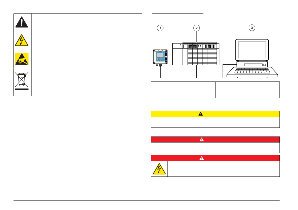
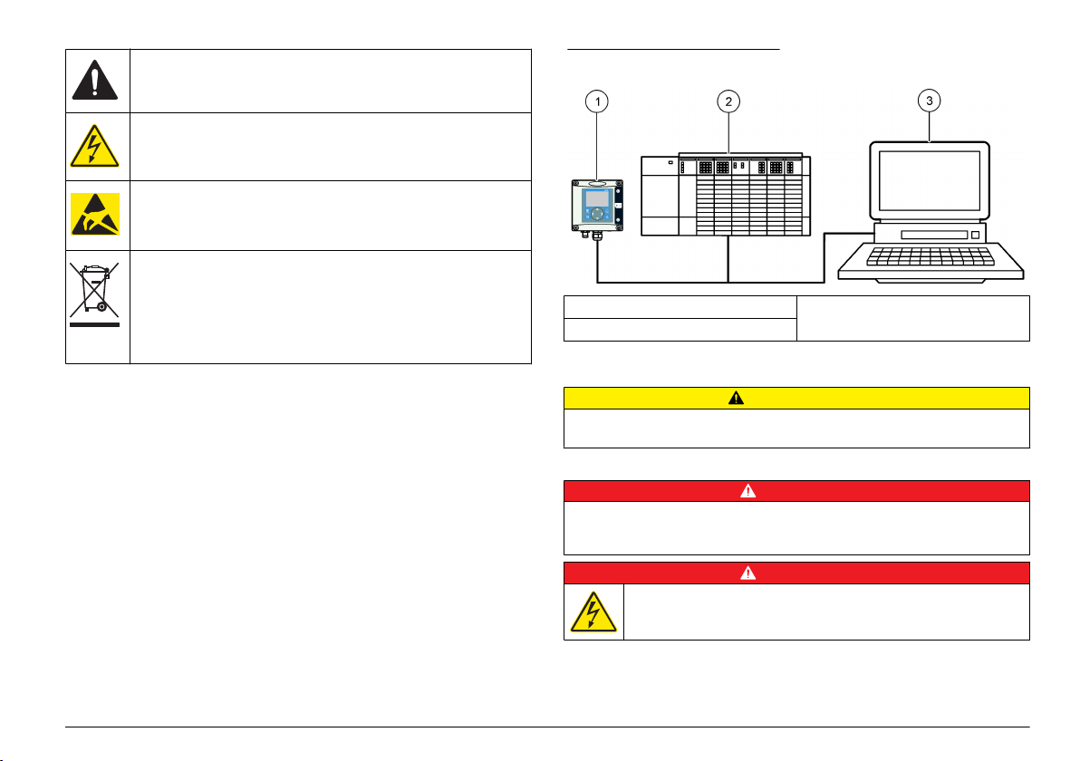
Figure 1 System overview
1 sc controller (Slave) 3 PC with software (Master class 2 e.g.
2 Programmable logic controller
(Master class 1)
PC include with CP5611 card)
Product overview
The sc controllers are the platform for all intelligent probes and analyzers.
The sc platform is a full digital communication system based on the open
Modbus standard. When a Profibus interface card is installed, the sc
controllers give the full range of standardized method values and
parameters.
The sc controllers are PNO/PTO certified Profibus DP/V1 devices. These
devices are compatible with master class 1 (PLC SCADA) and master
class 2 systems, e.g., engineering stations.
An overview of the system is shown in System overview. Profibus is
available as a factory or user installed item.
4 English
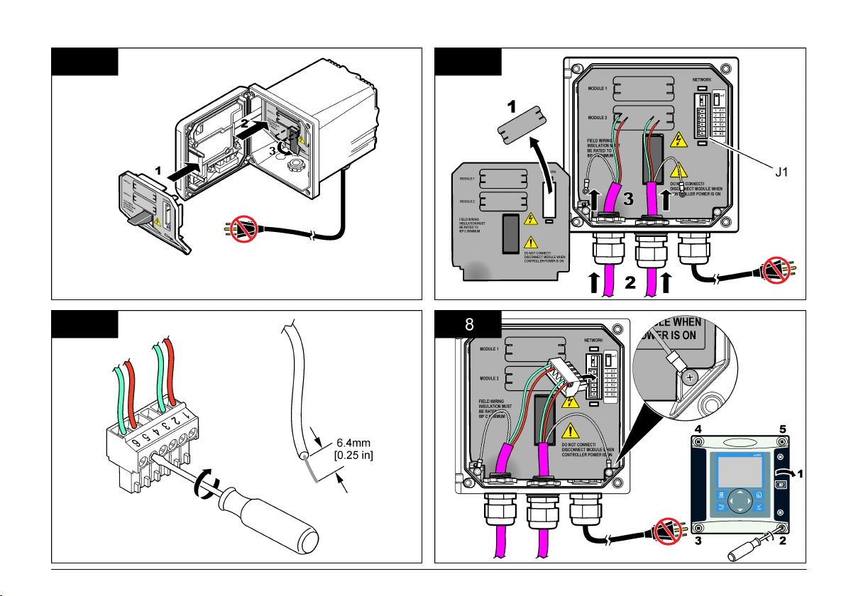
Installation
C A U T I O N
Personal injury hazard. Only qualified personnel should conduct the tasks
described in this section of the manual.
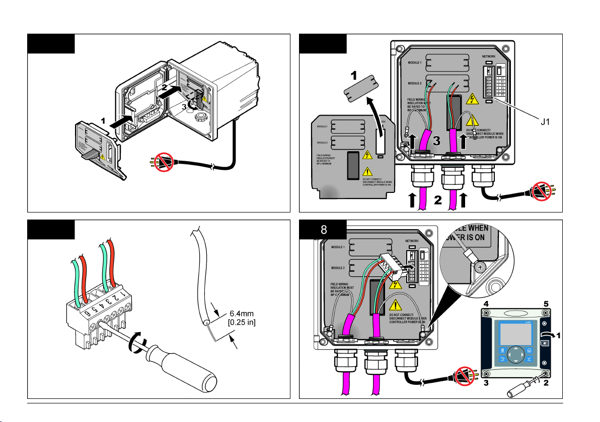
Install the module to the controller
Explosion Hazard. For the module installation in classified hazardous locations,
refer to the controller user manual for safety instructions.
Electrocution Hazard. Always remove power from the instrument before
making any electrical connections.
D A N G E R
D A N G E R
D A N G E R
Electrocution Hazard. High voltage wiring for the controller is conducted behind the
high voltage barrier in the controller enclosure. The barrier must remain in place
except when
for power, relays or analog and network cards.
installing modules, or when a qualified installation technician is wiring
Potential Instrument Damage. Delicate internal electronic components
damaged by static electricity, resulting in degraded performance
can be
or eventual failure.
N O T I C E
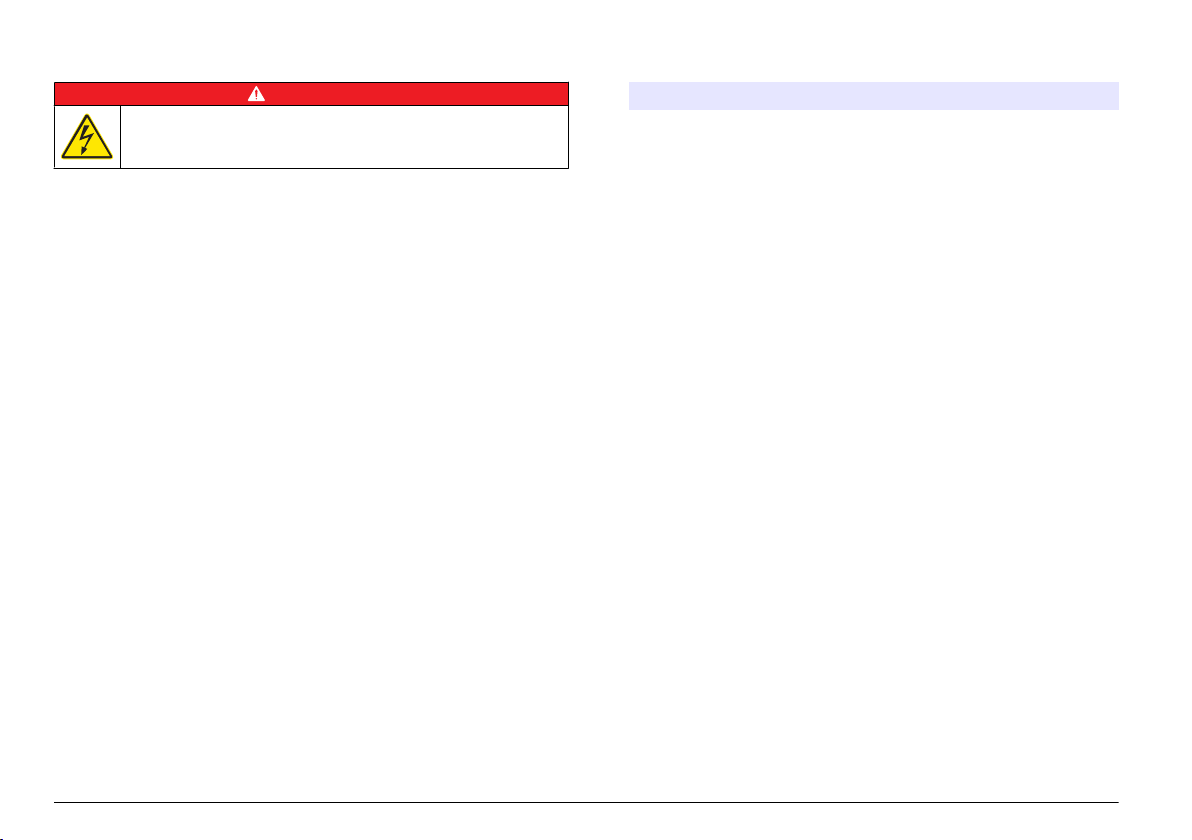
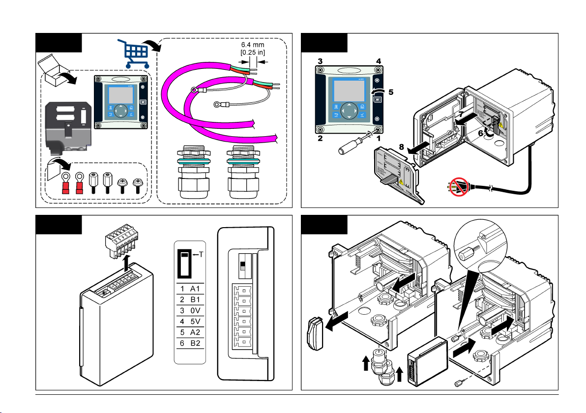
The Profibus network card supports RS485 communication. Terminal
block J1 provides the user connection to the Profibus network card. For
more wiring
details, refer to Installation Profibus and to the following steps
to install the Profibus network card.
Table 1 Profibus wiring with RS485
Connector Connector
block pin
number
J1 1 A1 (Input) green Input from the
2 B1 (Input) red Input from the
3 OV — —
4 5V — —
5 A2 (Output) green Output from the
6 B2 (Output) red Output from the
Signal Cable
color
Description
network card
network card
network card
network card
English 5
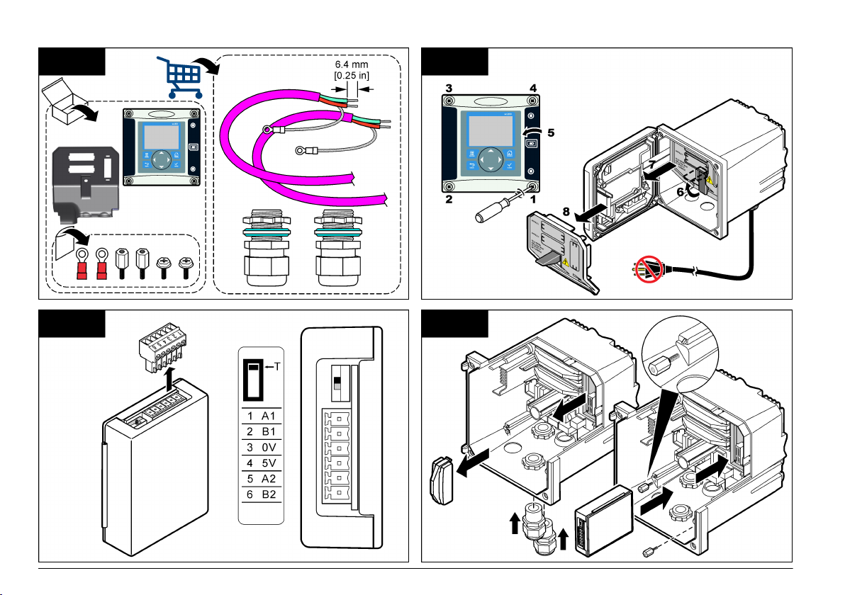
1 2
3 4
6 English
5 6
7 8
English 7
Configure the network
D A N G E R
Electrocution Hazard. Always remove power from the instrument before
making any electrical connections.
The Profibus network card provides an interface for RS485 connection.
Before use, the network card must be configured for the location in the
network. Use the switch settings on the top of the network card for
configuration (refer to the Installation section).
1. Termination switch–Termination Off. Set the switch to this position if
this is not the last slave on the bus.
2. Termination switch–Termination On («T» position). Set the switch to
this position if this is the last or only slave device on the bus.
Operation
User navigation
Refer to the controller documentation for keypad description and
navigation information.
Setup the network
When the Profibus network card is installed, the controller requires the
correct configuration of the device and data order.
Note: Refer to
information and controller setup.
1. Select Network setup from the Settings menu.
the controller documentation for keypad description, basic navigation
2. Select, enter or change values and then push the ENTER key.
Option Description
Telegram Manages the Telegram data structure. Auto configuration:
ProfibusDPSelects one of the following options:
The Telegram is automatically configured with 16 data bytes
from each sensor and the controller. In the Auto configuration
the Telegram structure can be viewed and a new auto
configuration can be started. Manual configuration: The
Telegram is configured manually. The devices and the device
data tags included in the Telegram can be selected.
• View configuration— Views the current Telegram data
configuration
• Start Auto
which may need some sensor setup changes
• Add/Remove devices— Selects the devices included in the
Telegram
• Add/remove tags— Selects telegram data tags for each
device
• Setup telegram mode— Selects the auto configuration
(default) or the manual configuration mode.
Address— Changes the slave address
Data order— Sets the sequence of bytes when transmitting
floating point values. A floating point value consists of 4 bytes.
• Normal = IEEE Float Big Endian (Default setting)—The pairs
are not swapped. This mode fits to all known Profibus master
systems.
• Swapped = IEEE Float word wise swapped: Swaps the first
pair of bytes with the last pair.
config— Starts a new auto configuration process
8 English

Option Description
Simulation Simulation— Simulates two floating point values and error/
Version Software version of the Profibus network card.
status to substitute a real instrument. Select the following
options and
setting:
• Simulation: Turns the simulation on or off.
• Period: Sets the time the first floating point value needs to
• Maximum: Sets the upper limit for the first floating point
• Minimum: Sets the lower limit for the first floating point value
• Error: The value entered in this menu will be set in the first
• Status: The value entered in this menu will be set in the
• Toggle: Changes the direction of the simulated ramp.
• Test/maint:
use the arrows to enter the values or use the default
Yes: Starts a simulation
No: Stops a simulation (Default setting)
run through the whole range between MINIMUM and
MAXIMUM—2 min (Default setting)
value.—20.0 (Default setting)
—10.0 (Default setting)
simulated tag—16 (Default setting)
second simulated tag—5 (Default setting)
Enabled: Sets the TEST/MAINT bit (0x0004) of every status
register of every configured slave in the cyclic Profibus
telegram to indicate the “Service” mode.
Disabled: Normal operation mode (Default setting)
Option Description
Location Edits the location name.
Status Status— Indicates the Profibus network card status
• Please wait: is shown until the network card has found all
configured slaves or is displayed when the card is new
configured and is searching for sensor connections
• PLC configure err: is shown when the network card has
received a wrong configuration of a PLC (Programmable
logic controller). Check the GSD file.
• Ready: is
to the Profibus. Check the address and/or the wiring.
• Online: is shown when the network card is in contact with
PLC and cyclic Data is sent
shown when the network card is ready to send data
Device order
The device
order in the Profibus telegram is fixed. The first and the second
installed sensors are always on position one and two and the controller is
on position three.
When no sensor is installed, the controller will stay in position three. The
position for the uninstalled sensors will be filled with 0xFF.
If two sensors are connected (maximum allowable) and scanned at the
same time, the installation order will be based on the location where the
sensor (or sensor module) is connected. The order is as follows:
• The top analog card connector.
• The bottom analog card connector.
• The left digital sensor connector.
• The right digital sensor connector.
Standard data structure (Auto configuration)
When the auto configuration (default) is selected, the Profibus network
card supplies a pre-defined data telegram for each connected device. The
telegram contains important data about the device.
The data block structure of the Profibus messages is standardized for all
types of probes. For the data block structure, refer to Profibus data
telegram register.
English 9
When the manual configuration is selected, the telegram data structure
can be configured by the user (refer to Setup the network on page 8).
Table 2 Profibus data telegram structure
Byte number Data Data type
1–2 Classified error Integer (2 bytes)
3–4 Classified status Integer (2 bytes)
5–8 Measurement 1 Floating (4 bytes)
9–12 Measurement 2 Floating (4 bytes)
13–16 Measurement 3 Floating (4 bytes)
Display values
The Profibus data block structure (Profibus message data block
structure) can
replace sc probes without changes in the PLC configuration.
The primary value is always the measured value.
The secondary value, if not available, is filled with zero.
The tertiary value, if not available, is filled with zero.
Figure 2 Profibus message data block structure
Process data controller block
The data
block for the sc controller is similar to the data block for sensors.
The structure of the sc controller data block is independent of the number
of connected sensors:
• sc controller_ERROR
• sc controller_STATUS
• Primary value
• Secondary value
• Tertiary value
Block 3 sc controller ERROR and Block 3 sc controller STATUS show the
data definitions for error and status 1 in the sc controller.
Table 3 Block 3 sc controller ERROR
Bit Error Note
0 Sensor 1 communication
error
1 Sensor 2 communication
error
2–15 Not used
A communication error has occurred
between the sc controller and sensor 1, the
sensor could be disconnected.
A communication error has occurred
between the sc controller and sensor 2, the
sensor could be disconnected.
Table 4 Block 3 sc controller STATUS
Bit Status1 Note
0 Sensor 1 installed First sensor has been installed to the sc controller. This
1 Sensor 2 installed Second sensor has been installed to the sc controller.
2 Relay A on
3 Relay B on
bit is set even if the sensor is disconnected after
installation.
This bit is set even if the sensor is disconnected after
installation.
10 English
Table 4 Block 3 sc controller STATUS (continued)
Bit Status1 Note
4 Relay C on
5 Relay D on
6–15 Not used
sc controller values
The following list show the data definitions for the sc controller:
• The sc controller primary value shows the result of a calculation.
The sc controller secondary value shows the 0–20 mA or the 4–20 mA
•
output from Channel 1.
• The sc controller tertiary value shows the 0–20 mA or the 4–20 mA
output from Channel 2.
IEEE 745 floating point definition
Profibus uses 32-bit single precision IEEE floating point definition. The
definition has twenty three bits for the mantissa and eight bits for the
exponent. There is one bit for the sign of the mantissa. Refer to Floating
point definition.
Figure 3 Floating point definition
1 Sign bit 4 Exponent
2 Exponent 5 Mantissa
3 Mantissa
Word wise swapping
Byte order inside Profibus telegram shows swapped and normal byte
sequences. In word wise swapping, the third and fourth bytes are
interchanged in
order with the first and second bytes. This results in a byte
order of 3 4 1 2.
Table 5 Byte order inside Profibus telegram
sc controller swapped sc controller normal
Byte T1 value 0 x 91 Byte T1 value 0 x 3F
Byte T2 value 0 x B9 Byte T2 value 0 x 67
Byte T3 value 0 x 3F Byte T3 value 0 x 91
Byte T4 value 0 x 67 Byte T4 value 0 x B9
English 11
Troubleshooting
W A R N I N G
Multiple hazards. Do not disassemble the instrument for maintenance or service.
If the
internal components must be cleaned or repaired, contact the manufacturer.
Error and status indicators
Error and
status words follow the same standard definition for all sc probes
and controllers.
Error messages lists bit position and error messages. Status indicator
messages lists bit position and status messages.
A bit value of zero shows the error or status condition that is not true.
A bit value of 1 shows the error or status condition that is true. For example,
if Bit 0 has the value of 1, an error has occurred during the last calibration.
Table 6 Error messages
Bit Message Indication
0 Measurement calibration
error
1 Electronic adjustment error An error has occurred during the last electronic
2 Cleaning error The last cleaning cycle failed
3 Measuring module error A failure has been detected in the Measurement
4 System re-initialization
error
5 Hardware error A general hardware error has been detected
6 Internal communication
error
7 Humidity error Excessive humidity has been detected within
8 Temperature error Temperature within the device exceeds a
An error has occurred during the last calibration
calibration
Module
Some settings are inconsistent and have been
reset to factory defaults
A communication failure within the device has
been detected
the device
specified limit
Table 6 Error messages (continued)
Bit Message Indication
9 — —
10 Sample warning Some action is required with the sample system
11 Questionable calibration
warning
12 Questionable
measurement warning
13 Safety warning A condition has been detected which may result
14 Reagent warning The reagent system requires attention
15 Maintenance required
warning
The last calibration may not be accurate
One or more of the device measurements are
out of range or are of questionable accuracy
in a safety hazard
The device requires maintenance
Table 7 Status indicator messages
Bit Message Indication
0 Calibration in progress The device is in a calibration mode.
1 Cleaning in progress The device is in a cleaning mode.
2 Service/Maintenance menu The device is in a service or maintenance
3 Common error The device has recognized an error. See Error
4 Measurement 0 Quality Bad Precision of measurement is out of specified
5 Measurement 0 Low Limit Measurement is below the specified range.
6 Measurement 0 High Limit Measurement is above the specified range.
7 Measurement 1 Quality Bad Precision of measurement is out of the
Measurements may not be valid.
Measurements may not be valid.
mode. Measurements may not be valid.
Register for Error Class.
limits.
specified limits.
12 English
Table 7 Status indicator messages (continued)
Bit Message Indication
8 Measurement 1 Low Limit Measurement is below the specified range.
9 Measurement 1 High Limit Measurement is above the specified range.
10 Measurement 2 Quality Bad Precision of measurement is out of the
specified limits.
11 Measurement 2 Low Limit Measurement is below the specified range.
12 Measurement 2 High Limit Measurement is above the specified range.
13 Measurement 3 Quality Bad Precision of measurement is out of the
specified limits.
14 Measurement 3 Low Limit Measurement is below the specified range.
15 Measurement 3 High Limit Measurement is above the specified range.
Event Log
Refer to Event Log for diagnostic device information.
Table 8 Event log
Event Description
ADDRESS Adjusted Profibus address
DATA ORDER Indicates the data order of 2 word variables in the cyclic and
acyclic Profibus telegram
SIMULATION Indicates if the simulated data is set into the cyclic Profibus
telegram.
Table 8 Event log (continued)
Event Description
SENSOR POWER Turn-on instant of the Profibus card
SET DATE/TIME Point in time set-up of the internal timer of the Profibus card
NEW CONFIG Point in time of a new configuration
AUTO CONFIGURE Point in time of a new menu setting
CODE VERSION Point in time of a new software download (Software version)
Replacement parts and accessories
Communication network cards and accessories
Description Item number
Profibus DP kit 9173900
Profibus M12 connector kit 9178500
Profibus M12 socket Profibus 9178200
Profibus M12 T plug 9178400
Product and Article numbers may vary for some selling regions. Contact
the appropriate distributor or refer to the company website for contact
information.
English 13
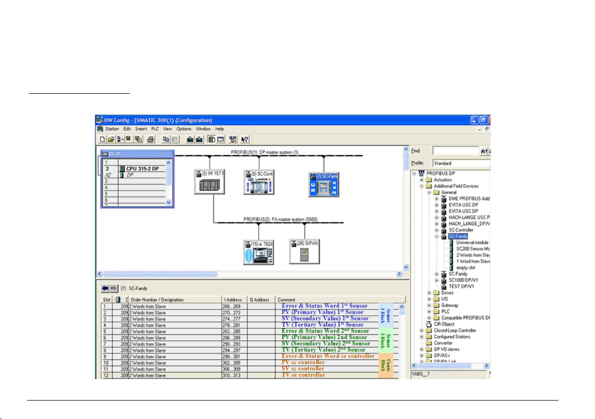
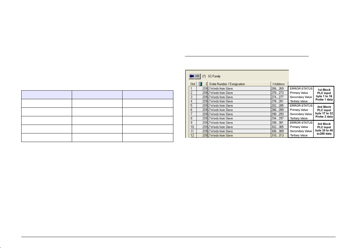
Example Simatic
When HALA09AC.GSD is imported, the slave will be located at PROFIBUS DP, ADDITIONAL FIELD DEVICES, GENERAL.
1. Select 2 Words from Slave network card.
Each module is 4 bytes of the input address range.
Figure 4 Example Simatic
14 English

Read data
For usual data sequence, use L PED at the module starting address to
read a floating point object. There is no need for more conversions.
Note: PEW/PED is the SIMATIC or German code mnemonic. Use PIW/PID for IEC
or English.
1. Read ERROR or STATUS words.
2. Use the L PEW instruction.
English 15
Technische Daten
Änderungen vorbehalten.
Technische Daten Details
Profibus-Protokoll Siemens ASIC SPC3
DP-Dienst DPV0-Slave
DP/DPV1-Dienste DPV1-Slave Klasse 1 und Klasse 2
I&M-Funktion
Adressänderung per Profibus-Master
Profibus-Baudraten 9,6 k, 19,2 k, 45,45 k, 93,75 k, 187,5 k, 500 k, 1,5
Anzeigen LED zur Anzeige des Datenaustauschmodus
Schnittstellentyp RS485
Konfigurierbare Parameter Datenfolge, Wortblocktausch für Gleitpunktwerte
Abmessungen (50 x 69,5 x 15,4) mm³
Betriebstemperatur -20 °C bis 85 °C (-4 ° bis 185 °F)
Betriebsspannung 8 V– 16 V
Maximale
Leistungsaufnahme
Zertifizierung Klasse I, Abschnitt 2 Gruppen A, B, C, D und
M, 3 M, 6 M, 12 M
Automatische Baudratenerkennung
2 W
Klasse I, Zone 2 Gruppe IIC, T4 gefährliche und
normale Standorte
Allgemeine Informationen
Der Hersteller
oder Folgeschäden, die aus Fehlern oder Unterlassungen in diesem
Handbuch entstanden. Der Hersteller behält sich jederzeit und ohne
vorherige Ankündigung oder Verpflichtung das Recht auf Verbesserungen
ist nicht verantwortlich für direkte, indirekte, versehentliche
an diesem Handbuch und den hierin beschriebenen Produkten vor.
Überarbeitete Ausgaben sind auf der Hersteller-Webseite erhältlich.
Sicherheitshinweise
Bitte lesen Sie dieses Handbuch komplett durch, bevor Sie dieses Gerät
auspacken, aufstellen oder bedienen. Beachten Sie alle Gefahren- und
Warnhinweise. Nichtbeachtung kann zu schweren Verletzungen des
Bedieners oder Schäden am Gerät führen.
Stellen Sie sicher, dass die Sicherheitseinrichtung dieses Messgerätes
nicht beeinträchtigt wird. Verwenden bzw. installieren Sie das
Messsystem nur auf solche Art und Weise, wie sie in diesem Handbuch
beschrieben wird.
Verwendung der Gefahrenhinweise
G E F A H R
Kennzeichnet eine mögliche oder drohende Gefahrensituation, die, wenn sie nicht
vermieden wird, zum Tod oder zu schweren Verletzungen führen kann.
W A R N H I N W E I S
Kennzeichnet eine mögliche oder drohende Gefahrensituation, die, wenn sie nicht
vermieden wird, zum Tod oder zu schweren Verletzungen führen kann.
Kennzeichnet eine mögliche Gefahrensituation, die zu geringeren oder moderaten
Verletzungen führen kann.
Kennzeichnet eine Situation, die, wenn sie nicht vermieden wird, das Gerät
beschädigen kann. Informationen, die besonders beachtet werden müssen.
V O R S I C H T
H I N W E I S
Warnhinweise
Lesen Sie alle am Gerät angebrachten Aufkleber und Hinweise.
Nichtbeachtung
Verletzungen oder Beschädigungen des Geräts zur
kann
Folge haben. Auf ein am Gerät angebrachtes Symbol wird im Handbuch
durch einen Hinweis GEFAHR oder ACHTUNG verwiesen.
16 Deutsch
Dieses Symbol kann am Gerät angebracht sein und verweist auf
Betriebs- und/oder Sicherheitshinweise in der Bedienungsanleitung.
Dieses Symbol weist auf die Gefahr eines elektrischen Schlages hin,
der tödlich sein kann.
Diese Symbol kennzeichnet das Vorhandensein von Geräten, die
empfindlich auf elektrostatische Entladung (ESD) reagieren und zeigt
an, dass Vorsicht erforderlich ist, um Schäden an diesem Gerät zu
vermeiden.
Elektrische Geräte, die mit diesem Symbol gekennzeichnet sind,
dürfen in Europa seit dem 12. August 2005 nicht mehr über das
öffentliche Entsorgungssystem entsorgt werden. Gemäß europäischer
lokal und national geltender Bestimmungen (EU-Richtlinie 2002/98/
EC) müssen europäische Verbraucher alte oder ausgediente Elektround Elektronikgeräte an die Hersteller zurückgeben, die diese für den
Verbraucher kostenlos entsorgen
Produktübersicht
Die sc Controller stellen die Plattform für alle intelligenten Sonden und
Analyzer dar. Bei der sc Plattform handelt es sich um ein vollständig
digitales Kommunikationssystem, welches auf dem offenen ModbusStandard basiert. Mit eingebauter Profibus-Schnittstellenkarte liefert der
sc Controller die gesamte Bandbreite der Standard-Verfahrenswerte und
-parameter.
Die sc Controller sind PNO/PTO zertifizierte Profibus DP/V1-Bausteine.
Diese Bausteine sind kompatibel mit den Master Class 1 (SPS SCADA)
und Master Class 2 Systemen, z.B. Engineering Tools (PDM).
Eine Übersicht
Profibus ist als werks- oder anwenderinstallierte Einheit erhältlich.
des Systems wird unten System overview dargestellt. Der
Abbildung 1 Systemübersicht
1 sc Controller (Slave) 3 PC mit Software (Master Klasse 2, z.
2 SPS (Master Klasse 1)
B. PC mit CP5611-Karte)
Installation
V O R S I C H T
Verletzungsgefahr. Nur qualifiziertes Personal sollte die in diesem Kapitel der
Bedienungsanleitung beschriebenen Aufgaben durchführen.
Einbau des Moduls im Controller
Explosionsgefahr. Sicherheitsanweisungen für die Installation des Moduls in als
gefährlich eingestuften Standorten finden Sie im Benutzerhandbuch für den
Controller.
Gefahr durch elektrischen Schlag. Trennen Sie das Gerät immer von
der Spannungsversorgung, bevor Sie elektrische Anschlüsse
herstellen.
G E F A H R
G E F A H R
Deutsch 17
G E F A H R
Gefahr durch elektrischen Schlag. Die Hochspannungsleitungen für die Steuerung
verlaufen hinter der Hochspannungssperre im Steuerungsgehäuse. Die Sperre
muss eingebaut bleiben, außer bei der Installation von Modulen oder wenn ein
qualifizierter Installationstechniker die Stromversorgung, Relais oder Netzkarten
anschließt.
Möglicher Geräteschaden Empfindliche interne elektronische Bauteile
können durch
Gerät mit verminderter Leistung funktioniert oder schließlich ganz
ausfällt.
statische Elektrizität beschädigt werden, wobei dann das
H I N W E I S
Die Profibus-Netzwerkkarte unterstützt die RS485-Kommunikation. Die
Klemmenleiste J1 stellt einen Benutzeranschluss für die ProfibusNetzwerkkarte zur Verfügung. Details zur Verdrahtung entnehmen Sie
bitte Installation Profibus und den folgenden Schritten zur Installation der
Profibus-Netzwerkkarte.
Tabelle 1 Profibus-Verdrahtung mit RS485
Stecker Pinnummer des
Steckerblocks
J1 1 A1 (Eingang) grün Eingang von der
2 B1 (Eingang) rot Eingang von der
3 OV — —
4 5 V — —
5 A2 (Ausgang) grün Ausgang von der
6 B2 (Ausgang) rot Ausgang von der
Signal Kabelfarbe Beschreibung
Netzwerkkarte
Netzwerkkarte
Netzwerkkarte
Netzwerkkarte
18 Deutsch
1 2
3 4
Deutsch 19
5 6
7 8
20 Deutsch
Konfigurieren des Netzwerks
G E F A H R
Gefahr durch elektrischen Schlag. Trennen Sie das Gerät immer von
der Spannungsversorgung, bevor Sie elektrische Anschlüsse
herstellen.
Die Profibus-Netzwerkkarte stellt einen Schnittstelle zum RS485-Bus
bereit. Bevor die Netzwerkkarte eingesetzt werden kann, muss sie
entsprechend ihrer Position im Netzwerk konfiguriert werden.
Konfigurieren Sie das Modul mit den Schaltern oben auf der
Netzwerkkarte (siehe Kapitel Installation).
1. Terminierungsschalter–Terminierung Aus. Stellen Sie den Schalter
auf diese Position, wenn dies nicht der letzte Slave auf dem Bus ist.
2. Terminierungsschalter–Terminierung Ein («T»-Position). Stellen Sie
den Schalter auf diese Position, wenn dies der letzte oder einzige
Slave auf dem Bus ist.
Vorgang
Benutzernavigation
Eine Beschreibung der Tastatur und Informationen zur Navigation
entnehmen Sie bitte der Controller-Dokumentation.
Netzwerkeinrichtung
Nachdem die Profibus Netzwerkkarte installiert wurde, fordert der
Controller die korrekte Gerätekonfiguration und Datenreihenfolge.
Hinweis: Eine Beschreibung der Tastatur und Informationen zur allgemeinen
Navigation sowie
Dokumentation.
1. Wählen Sie NETZWERK-SETUP aus dem Menü „Einstellungen“.
zur Einrichtung des Controllers entnehmen Sie bitte der Controller-
2. Wählen Sie
die Werte, ändern Sie diese oder geben Sie diese ein und
drücken Sie dann ENTER.
Optionen Beschreibung
Telegramm Verwaltet die Telegramm-Datenstruktur Automatische
Profibus DP Wählt eine der folgenden Optionen:
Konfiguration: Das Telegramm wird automatisch mit 16
Datenbytes von
Bei automatischer Konfiguration können die Telegrammstruktur
angezeigt und eine neue automatische Konfiguration gestartet
werden. Manuelle Konfiguration: Das Telegramm wird
manuell konfiguriert. Die Geräte und die Gerätedatenregister,
die im Telegramm enthalten sind, können ausgewählt werden.
• View configuration— (Konfiguration anzeigen) Zeigt die
aktuelle Konfiguration der Telegrammdaten an
• Start Auto config— (Automatische Konfiguration starten)
Startet einen neuen automatischen Konfigurationsprozess,
dessen Sensoreinrichtungen möglicherweise geändert
werden müssen
• Add/Remove devices— (Geräte hinzufügen/entfernen)
Wählt die im Telegramm enthaltenen Geräte aus
• Add/remove tags— (Register hinzufügen/entfernen) Wählt
die Telegrammdatenregister für jedes Gerät aus
• Setup telegram mode— (Telegrammmodus einrichten)
Wählt die automatische Konfiguration (Standard) oder die
manuelle Konfiguration aus.
Adresse— Ändert die Salve-Adresse
Datenfolge— Legt die Reihenfolge der Bytes für die
Übertragung der Gleitpunktwerte fest. Ein Gleitpunktwert
besteht aus 4 Byte.
• Normal = IEEE Float Big Endian (Standardeinstellung)— Die
Bytepaare sind nicht getauscht. Dieser Modus ist für alle
bekannten Profibus-Mastersysteme passend.
• Getauscht = IEEE Float Wortblocktausch: Erstes und letztes
Bytepaar sind getauscht.
jedem Sensor und dem Controller konfiguriert.
Deutsch 21

Optionen Beschreibung
Simulation Simulation— Simuliert zwei Gleitpunktwerte und Fehler/
Status zum Ersatz eines echten Instruments. Wählen Sie die
folgenden Optionen und geben Sie die Werte ein oder
verwenden Sie die Standardeinstellung:
• Simulation: Schaltet die Simulation ein oder aus.
Ja: Startet eine Simulation
Nein: Stoppt eine Simulation (Standardeinstellung)
• Dauer:Bestimmt die Zeit, die der erste Gleitpunktwert
benötigt, um durch den gesamten Bereich zwischen
MINIMUM und MAXIMUM zu laufen— 2 min
(Standardeinstellung).
• Maximum: Legt die Obergrenze für den ersten
Gleitpunktwert fest.— 20,0 (Standardeinstellung)
• Minimum: Legt die Untergrenze für den ersten
Gleitpunktwert fest— 10,0 (Standardeinstellung)
• Fehler: Der in dieses Menü eingegebene Wert wird in das
erste simulierte Register gesetzt)— 16
(Standardeinstellung)
• Status: Der in dieses Menü eingegebene Wert wird in das
zweite simulierte Register gesetzt)— 5
(Standardeinstellung)
• Toggle: Ändert die Richtung der simulierten Rampe.
• Service:
Aktiviert: Setzt das SERVICE-Bit (0x0004) jedes
Statusregisters jedes konfigurierten Slaves im zyklischen
Profibus-Telegramm, um den „Service“-Modus anzuzeigen.
Deaktiviert: Normaler Betrieb (Standardeinstellung)
Version Software-Version der Profibus-Netzwerkkarte.
Optionen Beschreibung
Standort Ändert den Namen des Messorts.
Status Status— Gibt den Status der Profibus-Netzwerkkarte an
• Bitte warten: wird angezeigt, bis die Netzwerkkarte alle
konfigurierten Slaves
konfiguriert wurde und nach angeschlossenen Sensoren
sucht.
• SPS Konfig.-Fehler wird angezeigt, wenn die
Netzwerkkarte eine falsche Konfiguration von der SPS
(Speicherprogrammierbare Steuerung) empfangen hat.
Überprüfen Sie die GSD-Datei.
• Bereit: wird angezeigt, wenn die Netzwerkkarte bereit ist,
Daten an den Profibus zu senden. Überprüfen Sie die
Adresse und/oder die Verdrahtung.
• Online: wird angezeigt, wenn die Netzwerkkarte mit der SPS
verbunden ist und zyklische Nachrichten ausgetauscht
werden.
gefunden hat oder wenn die Karte neu
Gerätereihenfolge
Die Reihenfolge der Geräte im Profibus-Telegramm ist fest vorgegeben.
Die ersten und zweiten installierten Sensoren befinden sich immer an
Position eins und zwei, der Controller immer an Position drei.
Auch wenn kein Sensor installiert ist, bleibt der Sensor an Position drei.
Die freien Sensorposition werden mit 0xFF gefüllt.
Wenn im
Vollausbau zwei Sensoren angeschlossen sind und gleichzeitig
gemessen werden, hängt die Reihenfolge der Sensoren von der
physischen Position ab, an der der Sensor (oder das Sensormodul)
angeschlossen ist. Die Reihenfolge ist:
• Der obere Analogkartenanschluss.
• Der untere Analogkartenanschluss.
• Der linke Digitalsensoranschluss.
• Der rechte Digitalsensoranschluss.
22 Deutsch
Standard-Datenstruktur (Automatische Konfiguration)
Wenn „Automatische Konfiguration» (Standard) ausgewählt wurde, stellt
die Profibus-Netzwerkkarte für jedes angeschlossene Gerät ein
vordefiniertes Datentelegramm bereit. Das Telegramm enthält wichtige
Daten über das Gerät.
Die Datenblockstruktur
der Profibus-Nachrichten ist für alle Sondentypen
standardisiert. Die Datenblockstruktur ist in Profibus data telegram
register gezeigt.
Wenn „Manuelle Konfiguration“ ausgewählt wird, kann die
Telegrammdatenstruktur vom Benutzer konfiguriert werden (siehe
Netzwerkeinrichtung auf Seite 21).
Tabelle 2 Struktur des Profibus-Datentelegramms
Byte-Nummer Daten Datentyp
1–2 Klassifizierter Fehler Integer (2 Byte)
3– 4 Klassifizierter Status Integer (2 Byte)
5–8 Messung 1 Gleitend (4 Byte)
9– 12 Messung 2 Gleitend (4 Byte)
13– 16 Messung 3 Gleitend (4 Byte)
Anzeigenwerte
Die Profibus-Datenblockstruktur (Profibus message data block structure)
kann sc Sonden ohne Änderungen der PLC-Konfiguration austauschen.
Der Erstwert ist immer der Messwert.
Der Zweitwert wird, wenn dieser nicht verfügbar ist, mit Null angegeben.
Der Drittwert wird, wenn dieser nicht verfügbar ist, mit Null angegeben.
Abbildung 2 Profibus Nachrichten-Datenblockstruktur
Prozessdatenblock des Controllers
Der Datenblock für den sc Controller ähnelt dem Datenblock für die
Sensoren. Die Struktur des Controller-Prozessdatenblocks ist von der
Anzahl der angeschlossenen Sensoren unabhängig:
•
sc Controller_FEHLER
sc Controller_STATUS
•
• Erstwert
• Zweitwert
• Drittwert
Block 3 sc controller ERROR und Block 3 sc controller STATUS zeigen
die Datendefinition für Fehler und Status 1 im sc Controller.
Deutsch 23
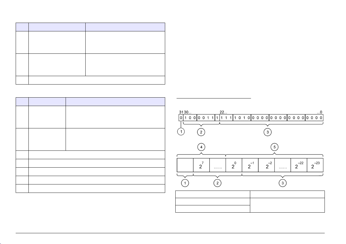
Tabelle 3 Block 3 sc Controller-FEHLER
Bit Fehler Hinweis
0 Sensor 1
Kommunikationsfehler
1 Sensor 2
Kommunikationsfehler
2–15 Nicht belegt
Zwischen dem sc Controller und dem
Sensor 1 ist ein Kommunikationsfehler
aufgetreten, der Sensor ist eventuell nicht
mehr angeschlossen.
Zwischen dem sc Controller und dem
Sensor 2 ist ein Kommunikationsfehler
aufgetreten, der Sensor ist eventuell nicht
mehr angeschlossen.
Tabelle 4 Block 3 sc Controller-STATUS
Bit Status1 Hinweis
0 Sensor 1 installiert Der erste Sensor wurde am sc Controller
1 Sensor 2 installiert Der zweite Sensor wurde am sc Controller
2 Relais A ein
3 Relais B ein
4 Relais C ein
5 Relais D ein
6–15 Nicht belegt
angeschlossen. Dieses
Sensor nach der Installation vom Controller getrennt
wurde.
angeschlossen. Dieses Bit ist gesetzt, selbst wenn der
Sensor nach der Installation vom Controller getrennt
wurde.
Bit ist gesetzt, selbst wenn der
sc Controller-Werte
Die folgende Liste gibt eine Aufstellung der Datendefinitionen für den sc
Controller:
• Der sc Controller-Erstwert gibt das Ergebnis einer Berechnung an.
Der sc Controller-Zweitwert gibt das 0– 20 mA- der das 4– 20 mA
•
Ausgangssignal von Kanal 1 an.
• Der sc Controller-Drittwert gibt das 0– 20 mA- der das 4– 20 mA
Ausgangssignal von Kanal 2 an.
IEEE 745-Gleitpunktdefinition
Profibus verwendet 32-Bit-Gleitpunktwerte mit einfacher Genauigkeit
nach IEEE-Definition. Die Definition sieht dreiundzwanzig Bit für die
Mantisse und acht Bit für den Exponenten vor. Das Vorzeichen der
Mantisse verwendet ein Bit. Siehe Floating point definition.
Abbildung 3 Gleitpunktdefinition
1 Vorzeichenbit 4 Exponent
2 Exponent 5 Mantisse
3 Mantisse
24 Deutsch
Wortblocktausch
Byte order inside Profibus telegram zeigt getauschte und normale Byte-
Reihenfolgen. Bei einem Wortblocktausch werden das dritte und vierte
der Reihenfolge mit dem ersten und zweiten Byte getauscht. Dies
Byte in
führt zu einer Byte-Reihenfolge von 3 4 1 2.
Tabelle 5 Byte-Reihenfolge im Profibus-Telegramm
sc Controller getauscht sc Controller normal
Byte T1 Wert 0 x 91 Byte T1 Wert 0 x 3F
Byte T2 Wert 0 x B9 Byte T2 Wert 0 x 67
Byte T3 Wert 0 x 3F Byte T3 Wert 0 x 91
Byte T4 Wert 0 x 67 Byte T4 Wert 0 x B9
Fehlersuche und -behebung
W A R N H I N W E I S
Mehrere Gefahren. Nehmen Sie das Gerät nicht zur Wartung auseinander. Falls
eine Reinigung oder Instandsetzung von externen Bauteilen erforderlich ist,
wenden Sie sich an den Hersteller.
Fehler- und Statusanzeigen
Die Fehler- und Statuswörter unterliegen den gleichen
Standarddefinitionen für alle sc Sonden und Controller.
Error messages
Status indicator messages listet die Bit-Positionen und deren
Statusnachrichten auf.
Ein Bit-Wert von Null zeigt an, dass der Fehler- oder Statuszustand nicht
Wahr ist.
Ein Bit-Wert von 1 zeigt an, dass der Fehler- oder Statuszustand Wahr ist.
Wenn zum Beispiel Bit 0 den Wert 1 hat, ist bei der letzten Kalibrierung ist
ein Fehler aufgetreten.
listet die Bit-Positionen und deren Fehlernachrichten auf.
Tabelle 6 Fehlermeldungen
Bit Meldung Erklärung
0 Kalibrierungsfehler Messung Bei der letzten Kalibrierung ist ein Fehler
1 Elektronischer
Justierungsfehler
2 Reinigungsfehler Der letzte Reinigungszyklus ist
3 Messmodulfehler Im Messmodul wurde ein Fehler entdeckt
4 Systemfehler bei Neustart Einige Einstellungen waren nicht
5 Hardware-Fehler Ein allgemeiner Hardware-Fehler wurde
6 Interner
Kommunikationsfehler
7 Feuchtigkeitsfehler Im Gerät wurde übermäßige Feuchtigkeit
8 Temperaturfehler Die Temperaturen im Gerät überschreiten die
9 — —
10 Probenwarnung Bitte überprüfen Sie das Probensystem
11 Warnung: zweifelhafte
Kalibrierung
12 Warnung: zweifelhafte
Messung
13 Sicherheitswarnung Es wurde ein Zustand entdeckt, der zu einer
aufgetreten
Bei der letzten elektronischen Kalibrierung ist
ein Fehler aufgetreten
fehlgeschlagen
durchgängig und wurden auf die
Standardwerte zurückgesetzt
entdeckt
Innerhalb des Geräts wurde ein
Kommunikationsfehler entdeckt
entdeckt
festgelegten Grenzwerte
Die letzte Kalibrierung war möglicherweise
ungenau
Eine oder mehrere Messung(en) des Geräts
lagen außerhalb des Toleranzbereichs oder
waren möglicherweise nicht genau
Gefahrensituation führen kann
Deutsch 25
Tabelle 6 Fehlermeldungen (fortgesetzt)
Bit Meldung Erklärung
14 Reagenswarnung Bitte überprüfen Sie das Reagenssystem
15 Warnung: Instandhaltung
erforderlich
Das Gerät benötigt eine Instandhaltung.
Tabelle 7 Nachrichten Statusanzeige
Bit Meldung Erklärung
0 Kalibrierungsablauf Das Gerät wurde in den
1 Reinigungsablauf Das Gerät wurde in den Reinigungsmodus
2 Service- /
Instandhaltungsmenü
3 Allgemeiner Fehler Das Gerät hat einen Fehler erkannt. Siehe
4 Messung 0 Qualität schlecht Die Genauigkeit der Messung liegt
5 Messung 0 Untergrenze Messung liegt unterhalb des
6 Messung 0 Obergrenze Messung liegt oberhalb des
7 Messung 1 Qualität schlecht Die Genauigkeit der Messung liegt
8 Messung 1 Untergrenze Messung liegt unterhalb des
9 Messung 1 Obergrenze Messung liegt oberhalb des
Kalibrierungsmodus versetzt. Die
Messungen sind möglicherweise ungültig.
versetzt. Die Messungen sind
möglicherweise ungültig.
Das Gerät ist im Service- oder
Instandhaltungsmodus. Die Messungen
sind möglicherweise ungültig.
Fehlerliste für Fehlerklasse.
außerhalb des Toleranzbereichs.
Toleranzbereichs.
Toleranzbereichs.
außerhalb des Toleranzbereichs.
Toleranzbereichs.
Toleranzbereichs.
Tabelle 7 Nachrichten Statusanzeige (fortgesetzt)
Bit Meldung Erklärung
10 Messung 2 Qualität schlecht Die Genauigkeit der Messung liegt
außerhalb des Toleranzbereichs.
11 Messung 2 Untergrenze Messung liegt unterhalb des
Toleranzbereichs.
12 Messung 2 Obergrenze Messung liegt oberhalb des
Toleranzbereichs.
13 Messung 3 Qualität schlecht Die Genauigkeit der Messung liegt
außerhalb des Toleranzbereichs.
14 Messung 3 Untergrenze Messung liegt unterhalb des
Toleranzbereichs.
15 Messung 3 Obergrenze Die Messung liegt über dem
Toleranzbereich.
Event Log
Für Gerätediagnose-Informationen siehe Event Log.
Tabelle 8 Ereignisprotokoll
Ereignis Beschreibung
ADRESSE Die eingestellte Profibus-Adresse
DATENREIHENFOLGE Gibt die Datenfolge der 2 Words langen Variablen in
zyklischen und azyklischen Profibus-Telegrammen an.
SIMULATION Gibt an, ob das zyklische Profibus-Telegramm
simulierte Daten enthält.
SENSOR STROM Zeitpunkt, zu dem die Profibus-Karte eingeschaltet
wurde.
DATUM/ZEIT Zeitpunkt, zu dem der interne Timer der Profibus-Karte
eingestellt wurde.
NEUE KONFIG Zeitpunkt einer neuen Konfiguration
26 Deutsch
Tabelle 8 Ereignisprotokoll (fortgesetzt)
Ereignis Beschreibung
AUTO KONFIG. Zeitpunkt einer neuen Menüeinstellung
SOFTWARE-VERS Zeitpunkt eines neuen Software-Downloads (Software-
Version)
Ersatzteile und Zubehör
Netzwerkkarten und Zubehör
Beschreibung Artikelnummer
Profibus DP-Satz 9173900
Profibus M12-Steckersatz 9178500
Beschreibung Artikelnummer
Profibus M12-Buchse Profibus 9178200
Profibus M12-T-Stecker 9178400
Produkt- und Artikelnummern können für einige Verkaufsgebiete
abweichen. Wenden
Sie sich an den zuständigen Händler oder schlagen
Sie die Kontaktinformationen auf der Webseite des Unternehmens nach.
Deutsch 27

Beispiel Simatic
Nach dem Import von HALA09AC.GSD steht der Slave unter PROFIBUS DP, WEITERE FELDGERÄTE, ALLGEMEIN.
1. Wählen Sie die Netzwerkkarte 2 Words from Slave.
Jedes Modul umfasst 4 Byte des Eingangsadressbereiches.
Abbildung 4 Beispiel Simatic
28 Deutsch

Daten lesen
Für die übliche Datenreihenfolge verwenden Sie L PED an der ModulStartadresse zum Lesen des Gleitpunktobjekts. Weitere Umwandlungen
sind nicht notwendig.
Hinweis: PEW/PED ist der SIMATIC oder deutsche Code-Mnemonik. Verwenden
Sie PIW/PID für IEC oder Englisch.
1. Lesen Sie die ERROR— oder STATUS-Wörter
2. Befolgen Sie die L PEW Anleitung.
Deutsch 29
Dati tecnici
I dati tecnici sono soggetti a modifica senza preavviso.
Dato tecnico Dettagli
Protocollo Profibus Siemens ASIC SPC3
Servizio DP Slave DPV0
Servizi DP/DPV1 Slave DPV1 classe 1 e classe 2
Funzione I&M
Indirizzo diverso in base al master Profibus
Baud rate Profibus 9.6k, 19.2k, 45.45k, 93.75k, 187.5k, 500k, 1.5M,
Indicatori LED per visualizzazione delle modalità di scambio
Tipo di interfaccia RS485
Parametri configurabili Scambio dati, basato su parole per valori in virgola
Dimensioni (50 x 69,5 x 15,4) mm³
Temperatura di
funzionamento
Tensione operativa 8V–16V
Consumo di potenza
massimo
Certificazione Classe I, Divisione 2 Gruppi A, B, C, D e Classe I,
3M, 6M, 12M
Rilevamento automatico baud rate
dati
mobile
da –20 a 85 °C (da –4 a 185 °F)
2 W
Zona 2
Gruppo IIC, T4 Aree pericolose e ordinarie
Informazioni generali
In nessun
danni diretti, indiretti, particolari, causali o consequenziali per qualsiasi
caso, il produttore potrà essere ritenuto responsabile in caso di
difetto o omissione relativa al presente manuale. Il produttore si riserva il
diritto di apportare eventuali modifiche al presente manuale e ai prodotti
ivi descritti in qualsiasi momento senza alcuna notifica o obbligo. Le
edizioni riviste sono presenti nel sito Web del produttore.
Informazioni sulla sicurezza
Prima di disimballare, installare o utilizzare l’apparecchio, si prega di
leggere l’intero manuale. Si raccomanda di leggere con attenzione e
rispettare le istruzioni riguardanti possibili pericoli o note cautelative. La
non osservanza di tali indicazioni potrebbe comportare lesioni gravi
dell’operatore o danni all’apparecchio.
Assicurarsi che la protezione fornita da questa apparecchiatura non sia
danneggia. Non utilizzare o installare questa apparecchiatura in modo
diverso da quanto specificato nel presente manuale.
Utilizzo dei segnali di avvertimento
P E R I C O L O
Indica una situazione di pericolo potenziale o imminente che, se non evitata,
potrebbe causare lesioni gravi o la morte.
A V V E R T E N Z A
Indica una situazione di pericolo potenziale o imminente che, se non evitata,
potrebbe comportare lesioni gravi, anche mortali.
A T T E N Z I O N E
Indica una situazione di pericolo potenziale che potrebbe comportare lesioni lievi
o moderate.
Indica una situazione che, se non evitata, può danneggiare lo strumento.
Informazioni che richiedono particolare attenzione da parte dell’utente.
A V V I S O
Etichette di avvertimento
Leggere tutte le etichette presenti sullo strumento. La mancata
osservanza delle stesse può causare lesioni personali o danni allo
strumento. A ogni simbolo riportato sullo strumento corrisponde
un’indicazione di pericolo o di avvertenza nel manuale.
30 Italiano
Loading…
Option Description
Display setup Configures the controller display
Set Date/Time Sets the controller time and date
Datalog setup Configures data logging options. Available only if Calculation has been setup.
Manage Data Select the device from the list of installed components to view the data or event log
Error Hold Mode Hold Outputs—Holds outputs at last known value when controller loses
communication with the sensor.
Transfer Outputs—Switches to transfer mode when controller loses communication
with the sensor. Outputs transfer to a pre-defined value.
Calculation Configures the controller math function
sc200 Information S/W VER:—Displays the current version of controller software
Bootloader VER:—Displays the current Bootloader version. The Bootloader is a file
that loads the main operating system for the controller
S/N:—Displays the controller serial number
Version:—Displays the current version of controller hardware
Discrete Input Setup Configures three discrete input channels
Language Assigns the language used in the controller
2. Select an option and push ENTER to activate the menu item.
Maintenance
CAUTION
Multiple hazards. Only qualified personnel must conduct the tasks described in this section of the
document.
Cleaning the controller
DANGER
Always remove power from the controller before performing maintenance activities.
1ote 1ever use flaPPaEle or corrosive solvents to clean any part of tKe controller. Use of tKese solvents Pay
degrade tKe environPental protection of tKe unit and Pay void tKe Zarranty.
1. Make sure the controller cover is securely closed.
2. Wipe the controller exterior with a cloth dampened with water, or with a mixture of water and mild
detergent.
Troubleshooting
Problem Resolution
No current output
Verify current output configuration.
Test current output signal using the Test/Maintenance submenu.
Input a current value and verify the output signal at the controller
connections.
Contact Technical Support.
26 (nglisK
- June 14, 2024
- HACH
Table of Contents
- Additional information
- Specifications
- General information
- Installation
- Operation
- Maintenance
- Troubleshooting
- Documents / Resources
- Read User Manual Online (PDF format)
- Download This Manual (PDF format)
DOC023.97.80077
Analog Combination pH/ORP Sensors
01/2023, Edition 3

Basic User Manual
Additional information
An expanded user manual is available on the manufacturer’s website.
Specifications
Specifications are subject to change without notice.
| Specification | Details |
|---|---|
| Dimensions (length/diameter) | Convertible: 150 mm (5.9 in.)/33 mm (1.3 in.), |
¾-in. NPT; Insertion: 150 mm
(5.9 in.)/22 mm (0.875 in.); Sanitary: 187 mm (7.4 in.)/22 mm (0.875 in.)
Pollution degree| 2
Overvoltage category| I
Protection class| III
Altitude| 2000 m (6562 ft) maximum
Operating temperature| 0 to 105 °C (32 to 221 °F)
Wetted materials| Convertible style (pH and ORP sensors): PPS body (glass
filled)
Insertion style (pH and ORP sensors): PVDF body
Sanitary style (pH sensor): 316 stainless steel sleeved PVDF body
Common materials for all sensor styles include PTFE double junction, glass
process electrode, and FPM/FKM O-rings
Measuring range| pH sensor: 0 to 14 pH¹ (or 2.00 to 14.00)
ORP sensor: -2000 to +2000 mV
Sensor cable| 4.5 m (15 ft)
Components| Corrosion-resistant materials, fully-submersible
Maximum flow rate| 2 m/s (6.6 ft/s) maximum
Immersion depth/pressure| 107 m (350 ft), 1050 kPa (100 psi) maximum
Pressure limit| 6.9 bar at 100 °C (100 psi at 212 °F)
Transmission distance| 100 m (328 ft) maximum when used with an sc digital
gateway
1000 m (3280 ft) maximum when used with an sc digital gateway and a
termination box
Temperature element| PT100, PT1000 (default), NTC300 or none depending on the
analog sensor
Calibration methods| 1- or 2-point automatic or manual
Sensor interface| Modbus RTU from sc digital gateway or pH/ORP module
Certifications| Listed by ETL (US/Canada) for use in Class 1, Division 2,
Groups A, B, C, D, Temperature Code T4 – Hazardous Locations with Hach SC
Controller.
Conforms to: CE, UKCA, FCC, ISED, ACMA, KC, CMIM, NM
¹Most pH applications are in the 2.5 to 12.5 pH range. Some industrial
applications require accurate measurement and control below 2 or above 12 pH.
In these special cases, please contact the manufacturer for further details.
General information
In no event will the manufacturer be liable for damages resulting from any
improper use of product or failure to comply with the instructions in the
manual. The manufacturer reserves the right to make changes in this manual and
the products it describes at any time, without notice or obligation. Revised
editions are found on the manufacturer’s website.
3.1 Safety information
The manufacturer is not responsible for any damages due to misapplication or
misuse of this product including, without limitation, direct, incidental and
consequential damages, and disclaims such damages to the full extent permitted
under applicable law. The user is soley responsible to identify critical
application risks and install appropriate mechanisms to protect processes
during a possible equipment malfunction.
Please read this entire manual before unpacking, setting up or operating this
equipment. Pay attention to all danger and caution statements. Failure to do
so could result in serious injury to the operator or damage to the equipment.
Make sure that the protection provided by this equipment is not impaired. Do
not use or install this equipment in any manner other than that specified in
this manual.
3.1.1 Use of hazard information
DANGER
Indicates a potentially or imminently hazardous situation which, if not
avoided, will result in death or serious injury.
WARNING
Indicates a potentially or imminently hazardous situation which, if not
avoided, could result in death or serious injury.
CAUTION
Indicates a potentially hazardous situation that may result in minor or
moderate injury.
NOTICE
Indicates a situation which, if not avoided, may cause damage to the
instrument. Information that requires special emphasis.
3.1.2 Precautionary labels
Read all labels and tags attached to the instrument. Personal injury or damage
to the instrument could occur if not observed. A symbol on the instrument is
referenced in the manual with a precautionary statement.
| This symbol, if noted on the instrument, references the instruction manual
for operation and/or safety information.
—|—
****| Electrical equipment marked with this symbol may not be disposed of in
European domestic or public disposal systems. Return old or end-of-life
equipment to the manufacturer for disposal at no charge to the user.
3.2 Product overview
This sensor is designed to work with a controller for data collection and
operation. Different controllers can be used with this sensor. This document
assumes sensor installation and use with an SC4500 Controller. To use the
sensor with other controllers, refer to the user manual for the controller
that is used.
Optional equipment, such as mounting hardware for the sensor, is supplied with
installation instructions. Several mounting options are available, allowing
the sensor to be adapted for use in many different applications.
3.3 Sensor styles
The sensor is available in different styles. Refer to Figure 1.

- Convertible, flat electrode —for a pipe tee or an open vessel
- Convertible, dome electrode —for a pipe tee or an open vessel
- Insertion —allows removal without stopping the process flow
- Sanitary —for install in a 2-inch sanitary tee
Installation
4.1 Mounting
WARNING
** Explosion hazard. For installation in hazardous (classified) locations,
refer to the instructions and control drawings in the controller Class 1,
Division 2 documentation. Install the sensor according to local, regional and
national codes. Do not connect or disconnect the instrument unless the
environment is known to be non-hazardous.
WARNING
** Explosion hazard. Make sure that the mounting hardware for the sensor
has a temperature and pressure rating sufficient for the mounting location.
CAUTION
Personal injury hazard. Broken glass can cause cuts. Use tools and personal
protective equipment to remove broken glass.
NOTICE
The process electrode at the pH sensor tip has a glass bulb, which can break.
Do not hit or push on the glass bulb.
NOTICE
The gold or platinum process electrode at the tip of the ORP sensor has a
glass shank (hidden by the salt bridge), which can break. Do not hit or push
on the glass shank.
- Install the sensor where the sample that comes into contact with the sensor is representative of the entire process.
- Refer to the expanded user manual on the manufacturer’s website for the available mounting hardware.
- Refer to the instructions supplied with the mounting hardware for installation information.
- Install the sensor at least 15° above horizontal.
- For immersion installations, put the sensor at least 508 mm (20 inches) from the aeration basin wall and immerse the sensor at least 508 mm (20 inches) into the process.
- Remove the protective cap before the sensor is put into the process water. Keep the protective cap for future use.
- Calibrate the sensor before use.
For examples of sensors in different applications, refer to Figure 2.

- Sanitary mount
- End of pipe immersion
- Flow-through mount
- Ball valve insertion
4.2 Connect the sensor to an SC Controller
Use one of the options that follows to connect the sensor to an SC Controller:
- Connect the sensor to an sc digital gateway, then connect the sc digital gateway to the SC Controller. The digital gateway converts the analog signal from the sensor to a digital signal.
- Install a sensor module in the SC Controller. Then, connect the sensor to the sensor module. The sensor module converts the analog signal from the sensor to a digital signal.
Refer to the instructions supplied with the sensor module or sc digital
gateway.
Operation
5.1 User navigation
Refer to the controller documentation for the touchscreen description and
navigation information.
5.2 Configure the sensor
Use the Settings menu to enter identification information for the sensor and
to change options for data handling and storage.
- Select the main menu icon, then select Devices. A list of all of the available devices shows.
- Select the sensor and select Device menu > Settings.
- Select an option.
• For sensors connected to a pH/ORP module, refer to Table 1.
• For sensors connected to an sc digital gateway, refer to Table 2.
Table 1 Sensors connected to pH/ORP module
| Option | Description |
|---|---|
| Name | Changes the name that corresponds to the sensor on the top of the |
measurement screen. The name is limited to 16 characters in any combination of
letters, numbers, spaces or punctuation.
Sensor S/N| Lets the user enter the serial number of the sensor.
The serial number is limited to 16 characters in any combination of letters,
numbers, spaces or punctuation.
Format| For pH sensors only—Changes the number of decimal places that are
shown on the measurement screen to XX.XX (default) or XX.X
Temperature| Sets the temperature units to °C (default) or °F.
Temperature element| pH sensors—Sets the temperature element for automatic
temperature compensation to PT100, PT1000 (default) or NTC300. If no element
is used, the type can be set to Manual and a value for temperature
compensation can be entered (default: 25 °C).
ORP sensors—Temperature compensation is not used. A temperature element can be
connected to the controller to measure temperature.
Filter| Sets a time constant to increase signal stability. The time constant
calculates the average value during a specified time—0 (no effect, default) to
60 seconds (average of signal value for 60 seconds). The filter increases the
time for the sensor signal to respond to actual changes in the process.
Pure H2O compensation| For pH sensors only—Adds a temperature-dependent
correction to the measured pH value for pure water with additives. Options:
None (default), Ammonia, Morpholine or User defined.
For process temperatures above 50 °C, the correction at 50 °C is used. For
user-defined applications, a linear slope (default: 0 pH/°C) can be entered.
Data logger interval| Sets the time interval for sensor and temperature
measurement storage in the data log—5, 30 seconds, 1, 2, 5, 10, 15 (default),
30, 60 minutes.
Reset to default values| Sets the Settings menu to the factory default
settings and resets the counters. All sensor information is lost.
Table 2 Sensors connected to sc digital gateway
| Option | Description |
|---|---|
| Name | Changes the name that corresponds to the sensor on the top of the |
measurement screen. The name is limited to 12 characters in any combination of
letters, numbers, spaces or punctuation.
Select sensor| Selects the type of sensor (pH or ORP).
Format| Refer to Table 1.
Temperature| Refer to Table 1.
Data logger interval| Sets the time interval for sensor and temperature
measurement storage in the data log—5, 10, 15, 30 seconds, 1, 5, 10, 15
(default), 30 minutes, 1, 2, 6, 12 hours.
Alternating current frequency| Selects the power line frequency to get the
best noise rejection. Options: 50 or 60 Hz (default).
Filter| Refer to Table 1.
Temperature element| Refer to Table 1.
Select standard buffer| For pH sensors only—Sets the pH buffers used for auto
correction calibration. Options: 4.00, 7.00, 10.00 (default set) or DIN 19267
(pH 1.09, 4.65, 6.79, 9.23, 12.75)
Note: Other buffers can be used if the 1-or 2-point manual correction is
selected for calibration.
Pure H2O compensation| Refer to Table 1.
1-,2-,3- or 4-point matrix correction can also be selected. The 1-,2-,3- or
4-point matrix correction are compensation methods pre-programmed in the
firmware.
Last calibration| Sets a reminder for the next calibration (default: 60 days).
A reminder to calibrate the sensor shows on the display after the selected
interval from the date of the last calibration.
For example, if the date of the last calibration was June 15 and Last
calibration is set to 60 days, a calibration reminder shows on the display on
August 14. If the sensor is calibrated before August 14, on July 15, a
calibration reminder shows on the display on September 13.
Sensor days| Sets a reminder for sensor replacement (default: 365 days). A
reminder to replace the sensor shows on the display after the selected
interval.
The Sensor days counter shows on the Diagnostics/Test > Counter menu.
When the sensor is replaced, reset the Sensor days counter on the
Diagnostics/Test > Counter menu.
Reset setup| Sets the Settings menu to the factory default settings and resets
the counters. All sensor information is lost.
5.3 Calibrate the sensor
WARNING
** Fluid pressure hazard. Removal of a sensor from a pressurized vessel can
be dangerous. Reduce the process pressure to below 7.25 psi (50 kPa) before
removal. If this is not possible, use extreme caution. Refer to the
documentation supplied with the mounting hardware for more information.
WARNING
Chemical exposure hazard. Obey laboratory safety procedures and wear all of
the personal protective equipment appropriate to the chemicals that are
handled. Refer to the current safety data sheets (MSDS/SDS) for safety
protocols.
CAUTION
Chemical exposure hazard. Dispose of chemicals and wastes in accordance with
local, regional and national regulations.
5.3.1 About sensor calibration
Calibration adjusts the sensor reading to match the value of one or more
reference solutions. The sensor characteristics slowly shift over time and
cause the sensor to lose accuracy. The sensor must be calibrated regularly to
maintain accuracy. The calibration frequency varies with the application and
is best determined by experience.
A temperature element is used to provide pH readings that are automatically
adjusted to 25 °C for temperature changes that affect the active and reference
electrode. This adjustment can be manually set by the customer if the process
temperature is constant.
During calibration, data is not sent to the datalog. Thus, the datalog can
have areas where the data is intermittent.
5.3.2 Change calibration options
For sensors connected to a pH/ORP module, the user can set a reminder or
include an operator ID with calibration data from the Calibration options
menu.
Note:** This procedure is not applicable to sensors connected to an sc
digital gateway.
- Select the main menu icon, then select Devices. A list of all of the available devices shows.
- Select the sensor and select Device menu > Calibration.
- Select Calibration options.
- Select an option.
| Option | Description |
|---|---|
| Select standard buffer | For pH sensors only—Sets the pH buffers used for auto |
correction calibration. Options: 4.00, 7.00, 10.00 (default set), DIN 19267
(pH 1.09, 4.65, 6.79, 9.23, 12.75) or NIST 4.00, 6.00, 9.00
Note: Other buffers can be used if the 1-or 2-point value calibration is
selected for calibration.
Calibration reminder| Sets a reminder for the next calibration (default: Off).
A reminder to calibrate the sensor shows on the display after the selected
interval from the date of the last calibration.
For example, if the date of the last calibration was June 15 and Last
calibration is set to 60 days, a calibration reminder shows on the display on
August 14. If the sensor is calibrated before August 14, on July 15, a
calibration reminder shows on the display on September 13.
Operator ID for calibration| Includes an operator ID with calibration data—Yes
or No (default). The ID is entered during the calibration.
5.3.3 pH calibration procedure
Calibrate the pH sensor with one or two reference solutions (1-point or
2-point calibration). Standard buffers are automatically recognized.
-
Put the sensor in the first reference solution (a buffer or sample of known value). Make sure that the sensor portion of the probe is fully immersed in the liquid (Figure 3).

-
Wait for the sensor and solution temperature to equalize. This can take 30 minutes or more if the temperature difference between the process and reference solution is significant.
-
Select the main menu icon, then select Devices. A list of all of the available devices shows.
-
Select the sensor and select Device menu > Calibration.
-
Select the type of calibration:
Option| Description
—|—
1-point buffer calibration
(or 1-point auto correction)| Use one buffer for calibration (e.g., pH 7). The
sensor automatically identifies the buffer during calibration.
Note: Make sure to select the buffer set in the Calibration > Calibration
options > Select standard buffer menu (or Settings > Select standard buffer
menu).
2-point buffer calibration
(or 2-point auto correction)| Use two buffers for calibration (e.g., pH 7 and
pH 4). The sensor automatically identifies the buffers during calibration.
Note: Make sure to select the buffer set in the Calibration > Calibration
options > Select standard buffer menu (or Settings > Select standard buffer
menu).
1-point value calibration
(or 1-point manual correction)| Use one sample of a known value (or one
buffer) for calibration. Determine the pH value of the sample with a different
instrument. Enter the pH value during calibration.
2-point value calibration
(or 2-point manual correction)| Use two samples of known value (or two
buffers) for calibration. Determine the pH value of the samples with a
different instrument. Enter the pH values during calibration. -
Select the option for the output signal during calibration:
Option| Description
—|—
Active| The instrument sends the current measured output value during the
calibration procedure.
Hold| The sensor output value is held at the current measured value during the
calibration procedure.
Transfer| A preset output value is sent during calibration. Refer to the
controller user manual to change the preset value. -
With the sensor in the first reference solution, push OK.
The measured value is shown. -
Wait for the value to stabilize and push OK.
Note: The screen may advance to the next step automatically. -
If applicable, enter the pH value and push OK.
Note: If the reference solution is a buffer, find the pH value on the
buffer bottle for the temperature of the buffer.
If the reference solution is a sample, determine the pH value of the sample
with a different instrument. -
For a 2-point calibration, measure the second reference solution as follows:
a. Remove the sensor from the first solution and rinse with clean water.
b. Put the sensor in the next reference solution, then push OK.
c. Wait for the value to stabilize and push OK.
Note: The screen may advance to the next step automatically.
d. If applicable, enter the pH value and push OK. -
Review the calibration result:
• “The calibration was successfully completed.”—The sensor is calibrated and
ready to measure samples. The slope and/or offset values are shown.
• “The calibration failed.” —The calibration slope or offset is outside of
accepted limits. Repeat the calibration with fresh reference solutions. Clean
the sensor if necessary. -
Push OK.
-
Return the sensor to the process and push OK.
The output signal returns to the active state and the measured sample value is
shown on the measurement screen.

5.3.4 ORP calibration procedure
Calibrate the ORP sensor with one reference solution (1-point calibration).
-
Put the sensor in the reference solution (a reference solution or sample of known value). Make sure that the sensor portion of the probe is fully immersed in the solution (Figure 4).
-
Select the main menu icon, then select Devices. A list of all of the available devices shows.
-
Select the sensor and select Device menu > Calibration.
-
Select 1-point value calibration (or 1-point manual correction).
-
Select the option for the output signal during calibration:
Option| Description
—|—
Active| The instrument sends the current measured output value during the
calibration procedure.
Hold| The sensor output value is held at the current measured value during the
calibration procedure.
Transfer| A preset output value is sent during calibration. Refer to the
controller user manual to change the preset value. -
With the sensor in the reference solution or sample, push OK. The measured value is shown.
-
Wait for the value to stabilize and push OK.
Note: The screen may advance to the next step automatically. -
If a sample is used for calibration, measure the ORP value of the sample with a secondary verification instrument. Enter the measured value, then push OK.
-
If a reference solution is used for calibration, enter the ORP value marked on the bottle. Push OK.
-
Review the calibration result:
• “The calibration was successfully completed.”—The sensor is calibrated and
ready to measure samples. The slope and/or offset values are shown.
• “The calibration failed.” —The calibration slope or offset is outside of
accepted limits. Repeat the calibration with fresh reference solutions. Clean
the sensor if necessary. -
Push OK.
-
Return the sensor to the process and push OK.
The output signal returns to the active state and the measured sample value is
shown on the measurement screen.

5.3.5 Temperature calibration
The instrument is calibrated at the factory for accurate temperature
measurement. The temperature can be calibrated to increase accuracy.
-
Put the sensor in a container of water.
-
Measure the temperature of the water with an accurate thermometer or independent instrument.
-
Select the main menu icon, then select Devices. A list of all of the available devices shows.
-
Select the sensor and select Device menu > Calibration.
-
For sensors connected to a pH/ORP module, do the steps that follow:
a. Select 1-point temperature calibration.
b. Wait for the value to stabilize, then push OK.
c. Enter the exact value and push OK. -
For sensors connected to an sc digital gateway, do the steps that follow:
a. Select Temperature adjustment.
b. Wait for the value to stabilize, then push OK.
c. Select Edit Temperature.
d. Enter the exact value and push OK. -
Return the sensor to the process and push the home icon.
5.3.6 Exit calibration procedure
- To exit a calibration, push the back icon.
- Select an option, then push OK.
| Option | Description |
|---|---|
| Quit calibration (or Cancel) | Stop the calibration. A new calibration must |
start from the beginning.
Return to calibration| Return to the calibration.
Leave calibration (or Exit)| Exit the calibration temporarily. Access to other
menus is allowed. A calibration for a second sensor (if present) can be
started.
5.3.7 Reset the calibration
The calibration can be reset to the factory default settings. All sensor
information is lost.
- Select the main menu icon, then select Devices. A list of all of the available devices shows.
- Select the sensor and select Device menu > Calibration.
- Select Reset to default calibration values (or Reset setup), then push OK.
- Push OK again.
5.4 Impedance measurements
To increase the reliability of the pH measurement system, the controller
determines the impedance of the glass electrodes. This measurement is taken
every minute. During diagnostics, the pH measurement reading will be on hold
for five seconds. If an error message appears, refer to Error list on page 17
for more details.
Note: This procedure does not apply to sensors connected to an sc digital
gateway.
To enable or disable the sensor impedance measurement:
- Select the main menu icon, then select Devices. A list of all of the available devices shows.
- Select the device and select Device menu > Diagnostics/Test.
- For sensors connected to a pH/ORP module, select Impedance status.
- Select Enabled or Disabled and push OK.
5.5 Modbus registers
A list of Modbus registers is available for network communication. Refer to
the manufacturer’s website for more information.
Maintenance
WARNING
Multiple hazards. Only qualified personnel must conduct the tasks described in
this section of the document.
WARNING
** Explosion hazard. Do not connect or disconnect the instrument unless the
environment is known to be non-hazardous. Refer to the controller Class 1,
Division 2 documentation for hazardous location instructions.
WARNING
** Fluid pressure hazard. Removal of a sensor from a pressurized vessel can
be dangerous. Reduce the process pressure to below 7.25 psi (50 kPa) before
removal. If this is not possible, use extreme caution. Refer to the
documentation supplied with the mounting hardware for more information.
WARNING
Chemical exposure hazard. Obey laboratory safety procedures and wear all of
the personal protective equipment appropriate to the chemicals that are
handled. Refer to the current safety data sheets (MSDS/SDS) for safety
protocols.
CAUTION
Chemical exposure hazard. Dispose of chemicals and wastes in accordance with
local, regional and national regulations.
6.1 Maintenance schedule
Table 3 shows the recommended schedule of maintenance tasks. Facility
requirements and operating conditions may increase the frequency of some
tasks.
Table 3 Maintenance schedule
| Maintenance task | 1 year | As necessary |
|---|---|---|
| Clean the sensor on page 15 | X | |
| Set by regulatory agencies or experience |
6.2 Clean the sensor
Pre-requisite: Prepare a mild soap solution with a non-abrasive dishwashing
detergent that does not contain lanolin. Lanolin leaves a film on the
electrode surface that can degrade the sensor performance.
Examine the sensor periodically for debris and deposits. Clean the sensor when
there is a buildup of deposits or when performance has degraded.
- Use a clean, soft cloth to remove loose debris from the end of the sensor. Rinse the sensor with clean, warm water.
- Soak the sensor for 2 to 3 minutes in the soap solution.
- Use a soft bristle brush to scrub the entire measuring end of the sensor.
- If debris remains, soak the measuring end of the sensor in a dilute acid solution such as < 5% HCl for a maximum of 5 minutes.
- Rinse the sensor with water and then return to the soap solution for 2 to 3 minutes.
- Rinse the sensor with clean water.
Note: Sensors with antimony electrodes for HF applications may require
additional cleaning. Contact technical support.
Always calibrate the sensor after maintenance procedures are done.
6.3 Prepare for storage
For short-term storage (when the sensor is out of the process for more than
one hour), fill the protective cap with pH 4 buffer or distilled water and put
the cap back on the sensor. Keep the process electrode and reference junction
salt bridge moist to avoid slow response when the sensor is returned to
operation.
For extended storage, repeat the short-term storage procedure every 2 to 4
weeks, depending on the environmental conditions. Refer to Specifications on
page 3 for temperature storage limits.
Troubleshooting
7.1 Intermittent data
During calibration, data is not sent to the datalog. Thus, the datalog can
have areas where the data is intermittent.
7.2 Test the pH sensor
Pre-requisites: Two pH buffers and a multimeter.
If a calibration fails, first complete the maintenance procedures in
Maintenance on page 15.
-
Put the sensor in a pH 7 buffer solution and wait for the temperature of the sensor and buffer to reach room temperature.
-
Disconnect the red (or green for 6-plug sensors) and white wires from the module or digital gateway.
-
Measure the resistance between the red (or green for 6-plug sensors) and white wires to verify the operation of the temperature element. The resistance should be between 1090 and 1105 ohms at approximately 25 ºC.
If the temperature element is good, reconnect the wires to the module. -
Push the main menu icon, then select Devices. A list of all of the available devices shows.
-
Select the device and select Device menu > Diagnostics/Test.
-
Select Sensor signals (or Signals). The reading should be between –50 and + 50 mV.
-
Rinse the sensor with water and put it in a pH 4 or pH 10 buffer solution. Wait for the temperature of the sensor and buffer to reach room temperature.
-
Compare the mV reading in the pH 4 or 10 buffer to the reading in the pH 7 buffer. The reading should differ by approximately 160 mV.
If the difference is less than 160 mV, call technical support.
7.3 Diagnostics/Test menu
The Diagnostics/Test menu shows current and historical information about the
sensor. Refer to Table 4. Push the main menu icon, then select Devices. Select
the device and select Device menu > Diagnostics/Test.
Table 4 Diagnostics/Test menu
| Option | Description |
|---|---|
| Module information | For sensors connected to a pH/ORP module only—Shows the |
version and the serial number for the sensor module.
Sensor information| For sensors connected to a pH/ORP module—Shows the sensor
name and the serial number entered by the user.
For sensors connected to an sc digital gateway—Shows the sensor model number,
and the sensor name entered by the user and the sensor serial number. Shows
the software version and driver version installed.
Last calibration| For sensors connected to a pH/ORP module only—Shows the
number of days since the last calibration was done.
Calibration history| For sensors connected to a pH/ORP module—Shows the
calibration slope and date of the previous calibrations.
For sensors connected to an sc digital gateway—Shows the calibration slope and
date of the last calibration.
Reset calibration history| For sensors connected to a pH/ORP module only—For
service use only
Impedance status| For pH sensors only—Refer to Impedance measurements on page
14.
Note: Impedance status is not available for sensors connected to an sc digital
gateway.
Sensor signals (or Signals)| For pH sensors connected to a pH/ORP module
only—Shows the current reading in mV.
For pH sensors connected to an sc digital gateway—Shows the current reading in
mV and the analog to digital converter counters.
If Impedance status is set to Enabled, shows the Sensor diagnostics value
(mV).
Sensor days (or Counter)| For sensors connected to a pH/ORP module—Shows the
number of days that the sensor has been in operation.
For sensors connected to an sc digital gateway—Shows the number of days that
the sensor and electrode(s) have been in operation. The Electrode days counter
is reset to zero when the firmware identifies that a defective electrode has
been replaced with an electrode that operates correctly.
To reset the Sensor days counter to zero, select Reset.
Reset the Sensor days counter when the sensor is replaced.
7.4 Error list
When an error occurs, the reading on the measurement screen flashes and all
outputs are held when specified in the Controller > Outputs menu. The screen
changes to red. The diagnostics bar shows the error. Push on the diagnostic
bar to show the errors and warnings. As an alternative, push the main menu
icon, then select Notifications > Errors.
A list of possible errors is shown in Table 5.
Table 5 Error list
| Error | Description | Resolution |
|---|---|---|
| pH value is too high! | The measured pH is > 14. | Calibrate or replace the |
sensor.
ORP value is too high!| The measured ORP value is > 2100 mV.
pH value is too low!| The measured pH is < 0.| Calibrate or replace the
sensor.
ORP value is too low!| The measured ORP value is < –2100 mV.
Offset value is too high.| The offset is > 9 (pH) or 200 mV (ORP).| Follow the
maintenance procedures for the sensor and then repeat the calibration, or
replace the sensor.
Offset value is too low.| The offset is < 5 (pH) or –200 mV (ORP).
Slope is too high.| The slope is > 62 (pH)/1.3 (ORP).| Repeat the calibration
with a fresh buffer or sample, or replace the sensor.
Slope is too low.| The slope is < 50 (pH)/0.7 (ORP).| Clean the sensor, then
repeat the calibration, or replace the sensor.
Temperature is too high!| The measured temperature is >130 °C.| Make sure that
the correct temperature element is selected.
Temperature is too low!| The measured temperature is < –10 °C.
The difference between the buffers is too small!| The buffers for 2-point auto
correction have the same value.| Complete the steps in Test the pH sensor on
page 16.
Sensor is missing.| The sensor is missing or disconnected.| Examine the wiring
and connections for the sensor and for the module (or digital gateway).
Temperature sensor is missing!| The temperature sensor is missing.| Examine
the wiring for the temperature sensor. Make sure that the correct temperature
element is selected.
Glass impedance is too low.| The glass bulb is broken or reached
end of life.| Replace the sensor. Contact technical support.
7.5 Warning list
A warning does not affect the operation of menus, relays and outputs. The
screen changes to an amber color. The diagnostics bar shows the warning. Push
on the diagnostic bar to show the errors and warnings. As an alternative, push
the main menu icon, then select Notifications > Warnings.
A list of possible warnings is shown in Table 6.
Table 6 Warning list
| Warning | Description | Resolution |
|---|---|---|
| pH is too high. | The measured pH is > 13. | Calibrate or replace the sensor. |
| ORP value is too high. | The measured ORP value is > 2100 mV. | |
| pH is too low. | The measured pH is < 1. | Calibrate or replace the sensor. |
| ORP value is too low. | The measured ORP value is < –2100 mV. | |
| Offset value is too high. | The offset is > 8 (pH) or 200 mV (ORP). | Follow the |
maintenance procedures for the sensor and then repeat the calibration.
Offset value is too low.| The offset is < 6 (pH) or –200 mV (ORP).
Slope is too high.| The slope is > 60 (pH)/1.3 (ORP).| Repeat the calibration
with a fresh buffer or sample.
Slope is too low.| The slope is < 54 (pH)/0.7 (ORP).| Clean the sensor, then
repeat the calibration.
Temperature is too high.| The measured temperature is > 100 °C.| Make sure the
right temperature element is used.
Temperature is too low.| The measured temperature is < 0 °C.
Temperature is out of range.| The measured temperature is > 100 °C or < 0 °C.
Calibration is overdue.| The Cal Reminder time has expired.| Calibrate the
sensor.
The device is not calibrated.| The sensor has not been calibrated.| Calibrate
the sensor.
Replace a sensor.| The Sensor days counter is more than the interval selected
for sensor
replacement. Refer to Configure the sensor on page 8.| Replace the sensor.
Reset the Sensor days counter on the Diagnostics /Test > Reset menu (or
Diagnostics/Test > Counter menu.
Calibration is in progress…| A calibration was started but not completed.|
Return to calibration.
Temperature is not calibrated.| The temperature sensor is not calibrated.| Do
a temperature calibration.
7.6 Event list
The diagnostic bar shows current activities such as configuration changes,
alarms, warning conditions, etc. A list of possible events is shown in Table
7. Previous events are recorded in the event log, which can be downloaded from
the controller. Refer to the controller documentation for data retrieval
options.
Table 7 Event list
| Event | Description |
|---|---|
| Calibration ready | The sensor is ready for calibration. |
| The calibration is OK. | The current calibration is good. |
| The time has expired. | The stabilization time during calibration expired. |
| There is no buffer available. | No buffer is detected. |
| Slope is too high. | The calibration slope is above the upper limit. |
| Slope is too low. | The calibration slope is below the lower limit. |
| Offset value is too high. | The calibration offset value for the sensor is |
above the upper limit.
Offset value is too low.| The calibration offset value for the sensor is below
the lower limit.
The calibration points are too close for a correct calibration.| The
calibration points are too similar in value for a 2-point calibration.
The calibration failed.| The calibration failed.
The calibration is high.| The calibration value is above the upper limit.
The reading is unstable.| The reading during calibration was unstable.
Change in configuration float value| The configuration was changed—floating
point type.
Change in configuration text value| The configuration was changed—text type.
Change in configuration| The configuration was reset to the default options.
Power is on.| The power was turned on.
ADC failure| The analog to digital conversion failed (hardware failure).
Flash erase| The flash memory was erased.
Temperature| The recorded temperature is too high or too low.
Start of 1-point manual calibration| Start of 1-point sample calibration
Start of 1-point auto calibration| Start of 1-point buffer calibration for pH
Start of 1-point temperature calibration| Start of 1-point temperature
calibration
Start of 2-point manual calibration| Start of 2-point sample calibration for
pH
Start of 2-point auto calibration| Start of 2-point buffer calibration for pH
End of 1-point manual calibration| End of 1-point sample calibration
End of 1-point auto calibration| End of 1-point buffer calibration for pH
End of 1-point temperature calibration| End of 1-point temperature calibration
End of 2-point manual calibration| End of 2-point sample calibration for pH
End of 2-point auto calibration| End of 2-point buffer calibration for pH
HACH COMPANY World Headquarters
P.O. Box 389, Loveland, CO 80539-0389 U.S.A.
Tel. 970-669-3050
800-227-4224 (U.S.A. only)
Fax 970-669-2932
orders@hach.com
www.hach.com| HACH LANGE GMBH
Willstätterstraße 11
D-40549 Düsseldorf, Germany
Tel. +49 (0) 2 11 52 88-320
Fax +49 (0) 2 11 52 88-210
info-de@hach.com
www.de.hach.com| HACH LANGE Sàrl
6, route de Compois
1222 Vésenaz
SWITZERLAND
Tel. +41 22 594 6400
Fax +41 22 594 6499
—|—|—


©Hach Company/Hach Lange GmbH,
2010, 2022.
All rights reserved. Printed in U.S.A.
Documents / Resources
| HACH
SC200 Analog Combination pH ORP
Sensors
[pdf] User Manual
SC200 Analog Combination pH ORP Sensors, SC200, Analog Combination pH ORP
Sensors, Combination pH ORP Sensors, pH ORP Sensors, Sensors
—|—
Read User Manual Online (PDF format)
Read User Manual Online (PDF format) >>
Download This Manual (PDF format)
Download this manual >>

DOC023.98.80051
Modbus Module
05/2013, Edition 3
User Manual
Bedienungsanleitung
Manuale d’uso
Manuel d’utilisation
Manual del usuario
Manual do utilizador
Návod k použití
Brugervejledning
Gebruikershandleiding
Podręcznik użytkownika
Bruksanvisning
Käyttöopas
Ръководство за потребителя
Felhasználói kézikönyv
Manual de utilizare
Naudotojo vadovas
Руководство пользователя
Kullanım Kılavuzu
Návod na obsluhu
Navodila za uporabo
Korisnički priručnik
Εγχειρίδιο λειτουργίας
Kasutusjuhend

English……………………………………………………………………………………………………………………………………………………………………………3
Deutsch………………………………………………………………………………………………………………………………………………………………………..15
Italiano………………………………………………………………………………………………………………………………………………………………………….28
Français……………………………………………………………………………………………………………………………………………………………………….41
Español………………………………………………………………………………………………………………………………………………………………………..55
Português……………………………………………………………………………………………………………………………………………………………………69
Čeština…………………………………………………………………………………………………………………………………………………………………………83
Dansk……………………………………………………………………………………………………………………………………………………………………………96
Nederlands………………………………………………………………………………………………………………………………………………………………..109
Polski………………………………………………………………………………………………………………………………………………………………………….122
Svenska……………………………………………………………………………………………………………………………………………………………………..137
Suomi………………………………………………………………………………………………………………………………………………………………………….150
български…………………………………………………………………………………………………………………………………………………………………162
Magyar……………………………………………………………………………………………………………………………………………………………………….176
Română……………………………………………………………………………………………………………………………………………………………………..190
lietuvių kalba……………………………………………………………………………………………………………………………………………………………..204
Русский……………………………………………………………………………………………………………………………………………………………………..216
Türkçe…………………………………………………………………………………………………………………………………………………………………………230
Slovenský jazyk……………………………………………………………………………………………………………………………………………………….242
Slovenski……………………………………………………………………………………………………………………………………………………………………255
Hrvatski………………………………………………………………………………………………………………………………………………………………………268
Ελληνικά…………………………………………………………………………………………………………………………………………………………………….282
eesti keel……………………………………………………………………………………………………………………………………………………………………297
2
Specifications
Use of hazard information
Specifications are subject to change without notice.
D A N G E R
Indicates a potentially or imminently hazardous situation which, if not avoided, will
Specification Details
result in death or serious injury.
RS232 output voltages > ±5 VDC
W A R N I N G
Selectable RS485 termination 120 Ω
Indicates a potentially or imminently hazardous situation which, if not avoided,
Selectable RS485 bias pull-up/pull-down 400 Ω
could result in death or serious injury.
C A U T I O N
General information
Indicates a potentially hazardous situation that may result in minor or moderate
injury.
In no event will the manufacturer be liable for direct, indirect, special,
incidental or consequential damages resulting from any defect or
N O T I C E
omission in this manual. The manufacturer reserves the right to make
changes in this manual and the products it describes at any time, without
Indicates a situation which, if not avoided, may cause damage to the instrument.
Information that requires special emphasis.
notice or obligation. Revised editions are found on the manufacturer’s
website.
Precautionary labels
Safety information
Read all labels and tags attached to the instrument. Personal injury or
damage to the instrument could occur if not observed. A symbol on the
N O T I C E
instrument is referenced in the manual with a precautionary statement.
The manufacturer is not responsible for any damages due to misapplication or
This symbol, if noted on the instrument, references the instruction
misuse of this product including, without limitation, direct, incidental and
manual for operation and/or safety information.
consequential damages, and disclaims such damages to the full extent permitted
under applicable law. The user is solely responsible to identify critical application
risks and install appropriate mechanisms to protect processes during a possible
equipment malfunction.
This symbol indicates that a risk of electrical shock and/or
electrocution exists.
Please read this entire manual before unpacking, setting up or operating
this equipment. Pay attention to all danger and caution statements.
Failure to do so could result in serious injury to the operator or damage
to the equipment.
Make sure that the protection provided by this equipment is not impaired.
Do not use or install this equipment in any manner other than that
specified in this manual.
English 3