
View the manual for the GW Instek SPS-3610 here, for free. This user manual comes under the category not categorized and has been rated by 2 people with an average of a 8.5. This manual is available in the following languages: English. Do you have a question about the GW Instek SPS-3610?
Ask your question here
Frequently asked questions
Can’t find the answer to your question in the manual? You may find the answer to your question in the FAQs about the GW Instek SPS-3610 below.
Is the manual of the GW Instek SPS-3610 available in English?
Yes, the manual of the GW Instek SPS-3610 is available in English .
Is your question not listed? Ask your question here
Изображения служат только для ознакомления,
см. техническую документацию
Выходное напряжение, В
36
Все документы
от 2 шт. —
39 100 руб.
от 8 шт. —
по запросу
6 000 руб.
× 1 =
6 000 руб.
1 шт.
на сумму 39 500 руб.
Плати частями
от 9 875 руб. × 4 платежа
Описание
Характеристики:
36 В, 10 А (100 мВ, 10 мА)
Цифровая индикация тока и напряжения,
Высокий КПД;
Высокая стабильность и малый уровень пульсаций;
Плавная регулировка выходных параметров ГРУБО/ТОЧНО;
Режимы стабилизации тока и напряжения;
Установка предела по току;
Защита от переполюсовки и перегрузки,
масса 3,3 кг
Технические параметры
| Тип источника | импульсный | |
| Выходное напряжение, В | 36 | |
| Выходной ток, А | 10 | |
| Госреестр РФ | Да | |
| Вес, кг | 4.42 |
Техническая документация
Видео
1:48
YouTube
Сроки доставки
Доставка в регион Сальск
| ПВЗ СДЭК | ||
| ПВЗ 5Post | ||
| ПВЗ Яндекс Доставка | ||
| Курьер | 29 мая1 | 362 руб.2 |
| ПВЗ Почта России | 30 мая1 | 426 руб.2 |
Цена и наличие в магазинах
| Ростов-на-Дону, проспект Соколо́ва, 53/182 |
нет в наличии |
Розничная цена: 39 500 руб.
Регулируемый импульсный источник питания SPS-3610 предназначен для питания радиотехнических устройств стабилизированным постоянным напряжением и током. Источник питания может использоваться в лабораториях и на производстве.
В источнике SPS3610 установлен импульсный преобразователь, который обеспечивает выходное напряжение от 0 до 36 В, выходной ток от 0 до 10А, максимальную мощность 360 Вт. С помощью регуляторов осуществляется плавная установка выходных параметров. Встроенная защита от перегрузки, от не правильного подключения и от переполюсовки обеспечивает стабильную работу прибора на протяжении всего срока службы.
|
Задняя панель SPS-3610 |
На задней панеле источника питания SPS-3610 установлены несколько разъемов, которые обеспечивают следующие возможности: Дистанционное управление прибором позволяет осуществлять включение и отключение выходного тока Подключение удаленной нагрузки к разъемам на задней панеле исключает просадки напряжения на соединительных проводах. |
Особенности источника питания SPS-3610
- Дополнительный выход для тока более 3 А;
- Низкий уровень внутреннего шума;
- Высокий уровень КПД до 70%;
- Регулировка выходных параметров по принципу грубо/точно;
- Одновременное отображение тока и напряжения;
- Небольшой вес и ручка для переноски.
Купить импульсный источник питания SPS-3610 получить консультацию специалистов, оформить заказ вы можете в магазине Союз-Прибор, позвонить по телефону или отправить письмо по электронной почте. Мы предоставляем только надёжное оборудование по самым выгодным ценам.

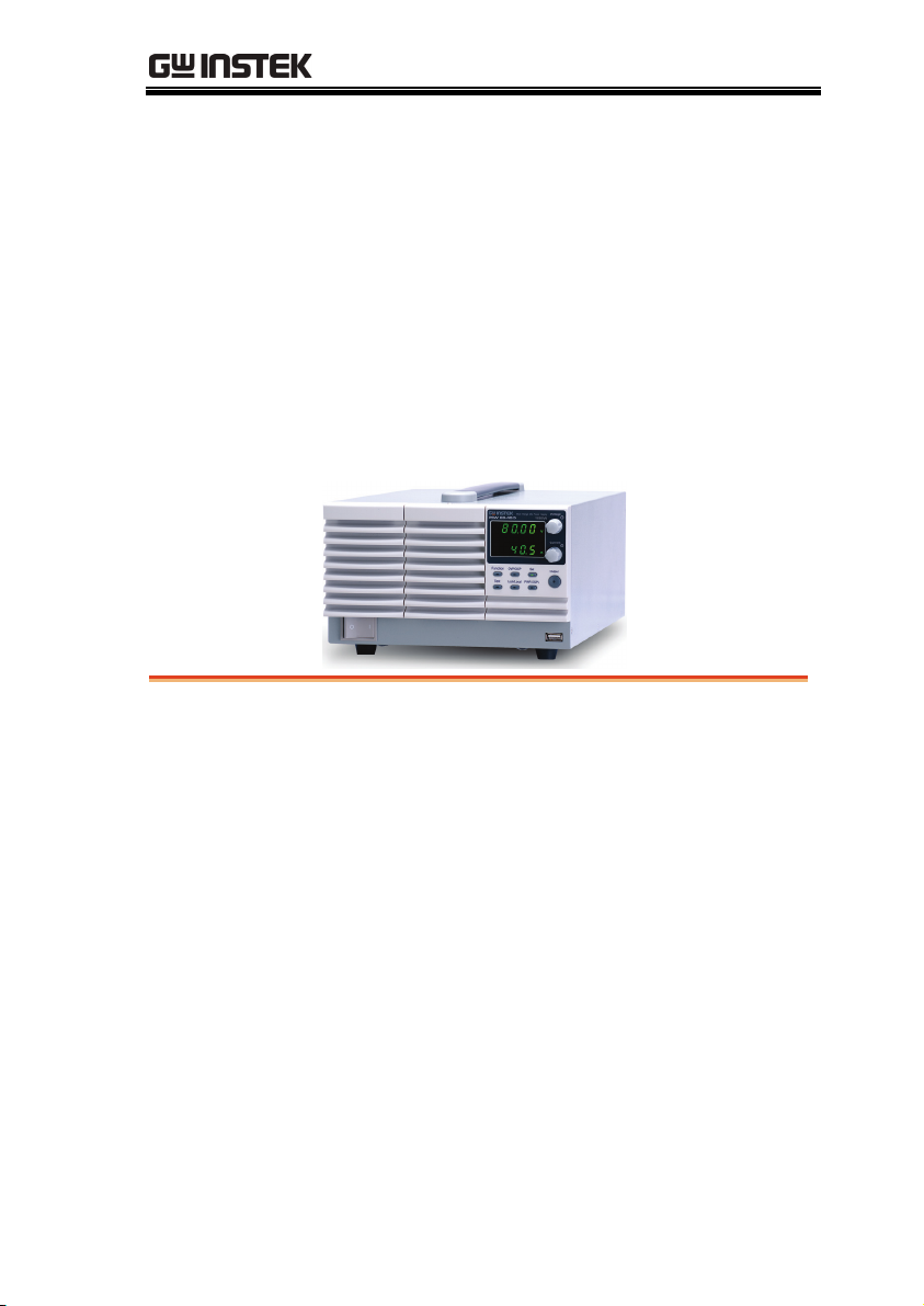
Multi-Range DC Power Supply
PSW Series
USER MANUAL
GW INSTEK PART NO. 82SW-80400M01
ISO-9001 CERTIFIED MANUFACTURER

This manual contains proprietary information, which is protected by
copyright. All rights are reserved. No part of this manual may be
photocopied, reproduced or translated to another language without
prior written consent of Good Will company.
The information in this manual was correct at the time of printing.
However, Good Will continues to improve products and reserves the
rights to change specification, equipment, and maintenance
procedures at any time without notice.
Good Will Instrument Co., Ltd.
No. 7-1, Jhongsing Rd., Tucheng Dist., New Taipei City 236, Taiwan.

SAFETY INSTRUCTIONS
Table of Contents
SAFETY INSTRUCTIONS …………………………………………… 5
GETTING STARTED ………………………………………………….. 9
PSW Series Overview ……………………… 10
Appearance …………………………………… 14
Theory of Operation ……………………….. 20
OPERATION ………………………………………………………….. 31
Set Up ………………………………………….. 33
Basic Operation …………………………….. 43
Parallel / Series Operation ………………. 54
Test Scripts …………………………………… 66
CONFIGURATION ………………………………………………….. 74
Configuration ………………………………… 75
ANALOG CONTROL ……………………………………………….. 88
Analog Remote Control Overview ……… 89
Remote Monitoring ………………………. 104
COMMUNICATION INTERFACE ………………………………. 107
Interface Configuration …………………. 108
MAINTENANCE ……………………………………………………. 112
FAQ ……………………………………………………………………. 114
APPENDIX …………………………………………………………… 116
PSW Default Settings ……………………. 116
Error Messages & Messages ………….. 118
LCD Display Format ……………………… 118
3

PSW Series User Manual
PSW Specifications ………………………. 119
PSW Dimensions …………………………. 128
Declaration of Conformity ……………… 131
INDEX …………………………………………………………………. 132
4
SAFETY INSTRUCTIONS
SAFETY INSTRUCTIONS
This chapter contains important safety
instructions that you must follow during
operation and storage. Read the following before
any operation to insure your safety and to keep
the instrument in the best possible condition.
Safety Symbols
These safety symbols may appear in this manual or on the
instrument.
WARNING
CAUTION
Warning: Identifies conditions or practices that
could result in injury or loss of life.
Caution: Identifies conditions or practices that
could result in damage to the PSW or to other
properties.
DANGER High Voltage
Attention Refer to the Manual
Protective Conductor Terminal
Earth (ground) Terminal
5
PSW Series User Manual
Do not dispose electronic equipment as unsorted
municipal waste. Please use a separate collection
facility or contact the supplier from which this
instrument was purchased.
Safety Guidelines
General
Guideline
CAUTION
Power Supply
WARNING
Do not place any heavy object on the PSW.
Avoid severe impact or rough handling that
Do not discharge static electricity to the PSW.
Use only mating connectors, not bare wires, for
Do not block the cooling fan opening.
Do not disassemble the PSW unless you are
(Measurement categories) EN 61010-1:2001 specifies the
measurement categories and their requirements as follows. the
PSW falls under category II.
Measurement category IV is for measurement performed at the
Measurement category III is for measurement performed in the
Measurement category II is for measurement performed on the
Measurement category I is for measurements performed on
AC Input voltage range: 85VAC~265VAC
Frequency: 47Hz~63Hz
To avoid electrical shock connect the protective
leads to damaging the PSW.
the terminals.
qualified.
source of low-voltage installation.
building installation.
circuits directly connected to the low voltage installation.
circuits not directly connected to Mains.
grounding conductor of the AC power cord to
an earth ground.
6

SAFETY INSTRUCTIONS
Cleaning the PSW
Operation
Environment
Storage
environment
Disconnect the power cord before cleaning.
Use a soft cloth dampened in a solution of mild
detergent and water. Do not spray any liquid.
Do not use chemicals containing harsh material
such as benzene, toluene, xylene, and acetone.
Location: Indoor, no direct sunlight, dust free,
almost non-conductive pollution (Note below)
Relative Humidity: 20%~ 85%
Altitude: < 2000m
Temperature: 0°C to 50°C
(Pollution Degree) EN 61010-1:2001 specifies the pollution degrees
and their requirements as follows. The PSW falls under degree 2.
Pollution refers to “addition of foreign matter, solid, liquid, or
gaseous (ionized gases), that may produce a reduction of dielectric
strength or surface resistivity”.
Pollution degree 1: No pollution or only dry, non-conductive
pollution occurs. The pollution has no influence.
Pollution degree 2: Normally only non-conductive pollution
occurs. Occasionally, however, a temporary conductivity caused
by condensation must be expected.
Pollution degree 3: Conductive pollution occurs, or dry, non-
conductive pollution occurs which becomes conductive due to
condensation which is expected. In such conditions, equipment
is normally protected against exposure to direct sunlight,
precipitation, and full wind pressure, but neither temperature
nor humidity is controlled.
Location: Indoor
Temperature: -25°C to 70°C
Relative Humidity: <90%
Disposal
Do not dispose this instrument as unsorted
municipal waste. Please use a separate collection
facility or contact the supplier from which this
instrument was purchased. Please make sure
discarded electrical waste is properly recycled to
reduce environmental impact.
7
PSW Series User Manual
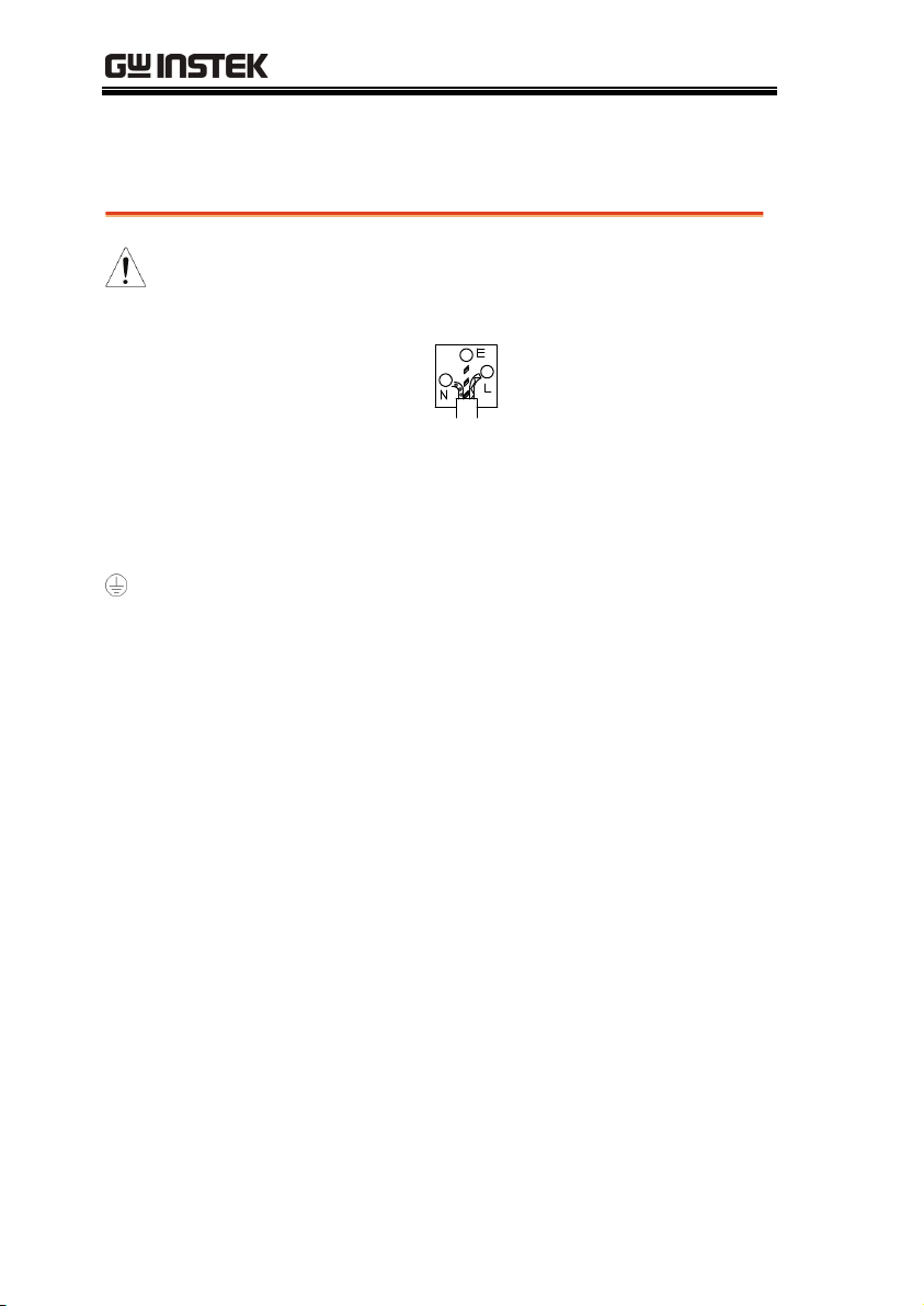
Power cord for the United Kingdom
When using the power supply in the United Kingdom, make sure
the power cord meets the following safety instructions.
NOTE: This lead/appliance must only be wired by competent persons
WARNING: THIS APPLIANCE MUST BE EARTHED
IMPORTANT: The wires in this lead are coloured in accordance with the
following code:
Green/ Yellow: Earth
Blue: Neutral
Brown: Live (Phase)
As the colours of the wires in main leads may not correspond with
the coloured marking identified in your plug/appliance, proceed
as follows:
The wire which is coloured Green & Yellow must be connected to
the Earth terminal marked with either the letter E, the earth symbol
or coloured Green/Green & Yellow.
The wire which is coloured Blue must be connected to the terminal
which is marked with the letter N or coloured Blue or Black.
The wire which is coloured Brown must be connected to the
terminal marked with the letter L or P or coloured Brown or Red.
If in doubt, consult the instructions provided with the equipment
or contact the supplier.
This cable/appliance should be protected by a suitably rated and
approved HBC mains fuse: refer to the rating information on the
equipment and/or user instructions for details. As a guide, a cable
of 0.75mm
conductors would normally require 13A types, depending on the
connection method used.
Any exposed wiring from a cable, plug or connection that is
engaged in a live socket is extremely hazardous. If a cable or plug is
deemed hazardous, turn off the mains power and remove the cable,
any fuses and fuse assemblies. All hazardous wiring must be
immediately destroyed and replaced in accordance to the above
standard.
2
should be protected by a 3A or 5A fuse. Larger
8
GETTING STARTED
GETTING STARTED
This chapter describes the power supply in a
nutshell, including its main features and front /
rear panel introduction. After going through the
overview, please read the theory of operation to
become familiar with the operating modes,
protection modes and other safety considerations.
PSW Series Overview ………………………………………………. 10
Series lineup ……………………………………………………………………………………………….. 10
Main Features …………………………………………………………………………………………….. 11
ccessories …………………………………………………………………………………………………. 11
Package Contents ……………………………………………………………………………………….. 13
Appearance …………………………………………………………… 14
PSW Front Panel ……………………………………………………………………………………….. 14
Rear Panel ………………………………………………………………………………………………….. 17
9
PSW Series User Manual
PSW Series Overview
Series lineup
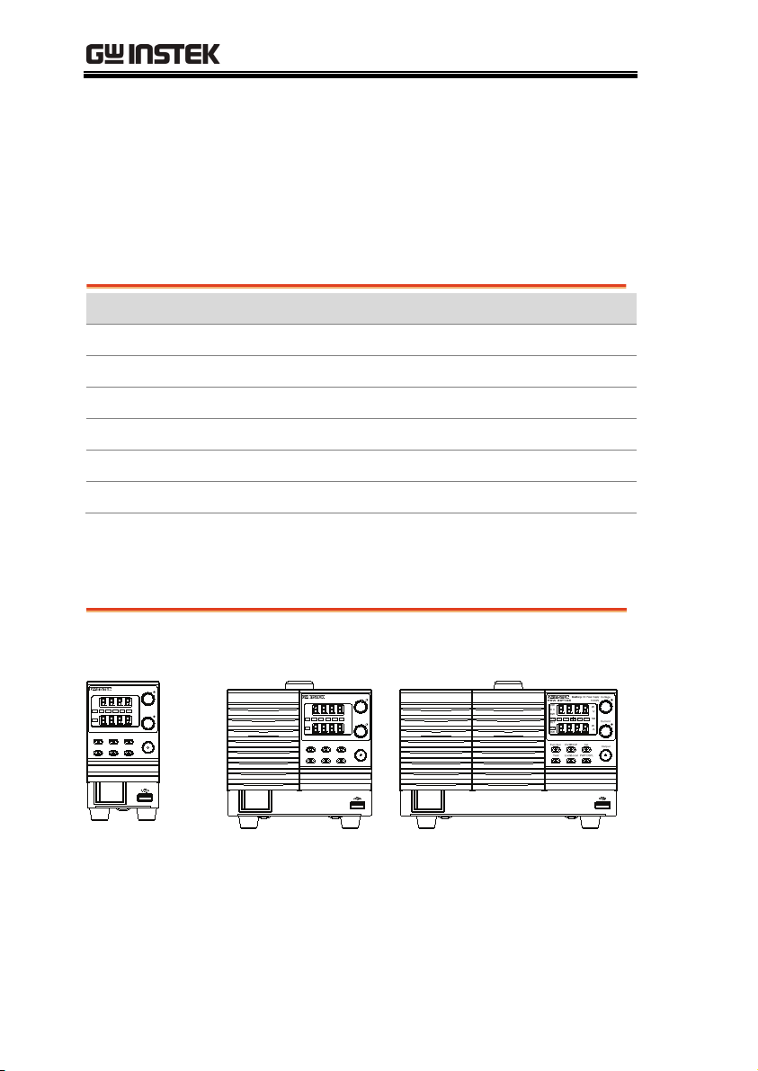
The PSW series consists of 6 models, divided into 3 different model
types covering 3 power capacities: Type I (360 Watt), Type II (720
Watt) and Type III (1080 Watt).
Model name Type Voltage Rating Current Rating Power
PSW 30-36 Type I 0~30V 0~36A 360W
PSW 80-13.5 Type I 0~80V 0~13.5A 360W
PSW 30-72 Type II 0~30V 0~72A 720W
PSW 80-27 Type II 0~80V 0~27A 720W
PSW 30-108 Type III 0~30V 0~108A 1080W
PSW 80-40.5 Type III 0~80V 0~40.5A 1080W
Apart from the differences in output, each unit differs in size. The
720 and 1080 watt models are larger than the 360 watt models to
accommodate the increase in power.
360 Watt models
Type I
Voltage
Multi-Range DC Power Supply
360W
PSW 30-36
VSR
W
C V
V
RMT
%W10080604020
ALM
Current
DLY
W
C C
A
ISR
Function OVP/OCP S et
Output
PWR DSPLLock/LocalTest
720 Watt models
Type I I
Multi-Range DC Power Supply
PSW 30-72
VSR
C V
RMT
ALM
DLY
C C
ISR
Function OVP/OCP Set
PWR DSPLLock/LocalTest
1080 Watt models
Type III
Voltage
720W
W
V
%W10080604020
Current
W
A
Output
10

Main Features
GETTING STARTED
Performance
Features
Interface
High performance/power
Power efficient switching type power supply
Low impact on load devices
Fast transient recovery time of 1ms
Fast output response time
OVP, OCP and OTP protection
Adjustable voltage and current slew rates
User adjustable bleeder control to quickly
dissipate the power after shutdown to safe
levels.
Extensive remote monitoring and control
options
Support for serial and parallel connections
Power on configuration settings.
Supports test scripts
Web server monitoring and control
Ethernet port
Analog connector for analog voltage and current
monitoring
USB host and device port
Accessories
Standard
Accessories
Region dependant User manual
4323-30600101 Power cord (Type I/II)
Part number Description
11
PSW Series User Manual
4320-91001101 Power cord (Type III)
63SC-XF100201 Output terminal cover: top
63SC-XF100301 Output terminal cover:
bottom
GTL-123 Test leads: 1x red, 1x black
PSW-004 Basic Accessory Kit:
M4 terminal screws and
washers x2, M8 terminal
bolts, nuts and washers x2,
Air filter x1, Analog control
protection dummy x1,
Analog control lock level x1
Optional
Part number Description
Accessories
GET-001 Extended terminal
PSW-001 Accessory Kit:
Pin contact x10, Socket x1,
Protection cover x1
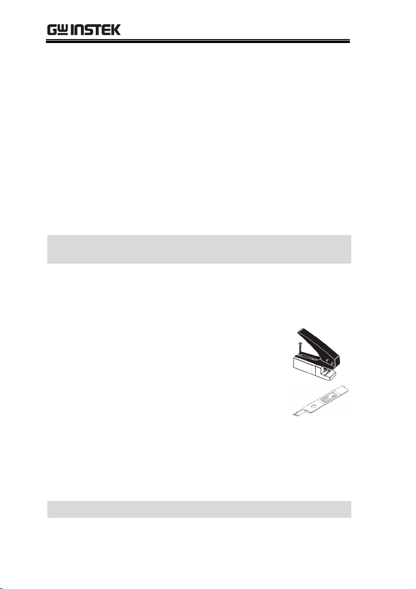
PSW-002 Simple IDC
Tool
PSW-003 Contact
Removal Tool
GRA-410-J Rack mount adapter (JIS)
GRA-410-E Rack mount adapter (EIA)
GUG-001 GPIB to USB adapter
GTL-246 USB Cable
57RG-30B00201 Large filter (Type II/III)
Download Name Description
psw_cdc.inf USB driver
12
GETTING STARTED
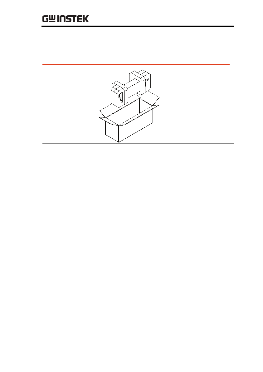
Package Contents
Check the contents before using the PSW.
Opening the box
Contents
(single unit)
Main unit
Output terminal cover
(top x1, bottom x1)
Test leads (red x1,
black x1)
M4 terminal screws
and washers x2
Air filter x1
Power cord x1 (region
dependent)
Analog control
protection dummy x1
Analog control lock
lever x1
M8 terminal bolts,
nuts and washers X2
13
PSW Series User Manual
Appearance
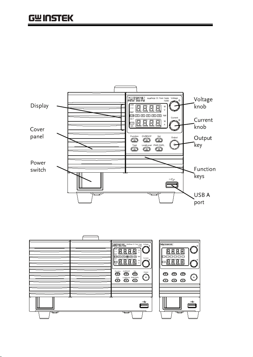
PSW Front Panel
PSW 80-27, PSW 30-72 (720W)
PSW 80-40.5, PSW 30-108 (1080W) PSW 80-13.5,
PSW 30-36 (360W)
Multi-Range DC Power Supply
PSW 30-36
VSR
C V
RMT
ALM
DLY
C C
ISR
Function OVP/OCP Set
14
360W
W
V
%W10080604020
W
A
PWR DSPLLock/LocalTest
Voltage
Current
Output
GETTING STARTED
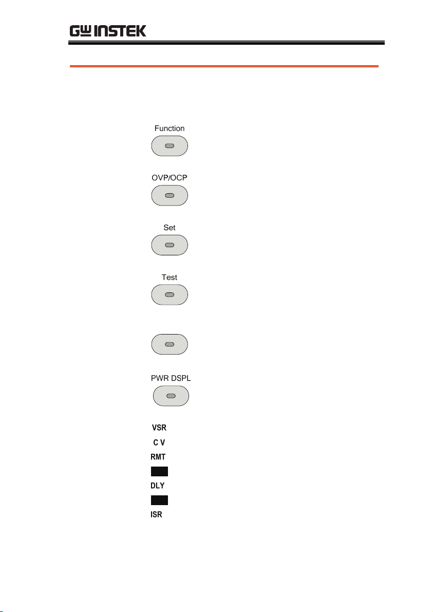
Function Keys
The Function keys along with the Output key will
light up when a key is active.
The Function key is used to
configure the power supply.
Set the over current or over
voltage protection levels.
Sets the current and voltage limits.
Used to run customized scripts for
testing.
Lock/Local
Locks or unlocks the panel keys to
prevent accidentally changing
panel settings.
Toggles the display from viewing
V/AV/WA/W.
Display
Indicators
ALM
C C
Voltage Slew Rate
Constant Voltage Mode
Remote Control Mode
Alarm on
Delay Outpu
Constant Current Mode
Current Slew Rate
15
PSW Series User Manual
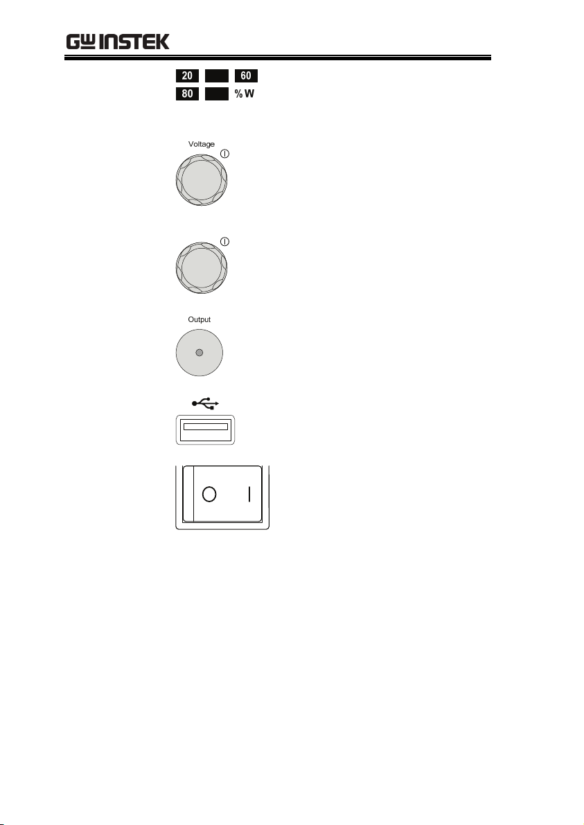
Voltage Knob
Current Knob
Output
USB
Power Switch
40
100
Current
Power bar
Indicates the current power output
as a percentage.
Sets the voltage.
Sets the current.
Press to turn on the output. The
Output key will light up when the
output is active.
USB A port for data transfer,
loading test scripts etc.
Used to turn the power on/off.
16
GETTING STARTED
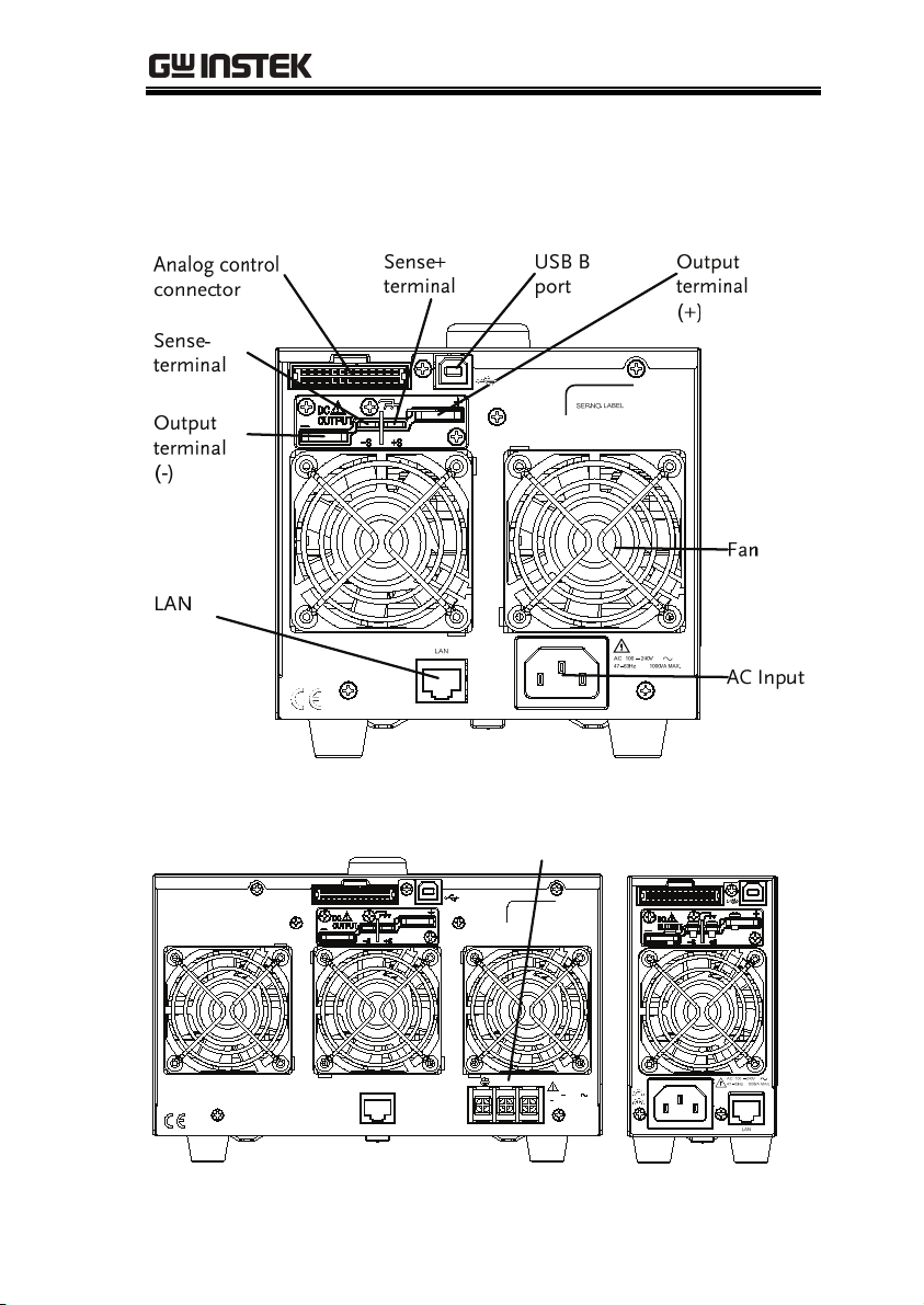
Rear Panel
PSW 80-27, PSW 30-72 (720W)
PSW 80-40.5, PSW 30-108 (1080W) PSW 80-13.5,
PSW 30-36 (360W)
AC Input
SER.NO. LABEL
LAN
LN
100 240VAC
47 63Hz
1500VA MAX.
17
PSW Series User Manual
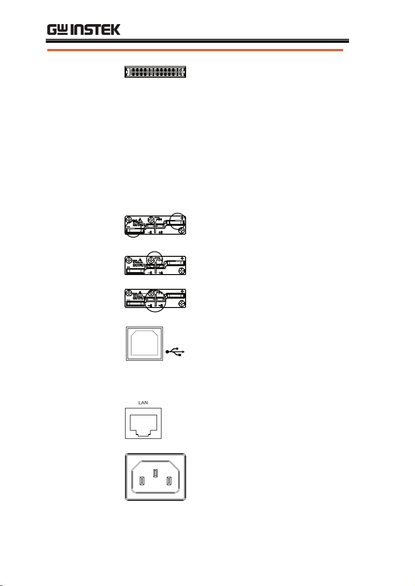
Analog Control
Connector
Output Terminals
USB B port
Standard 26 pin MIL connector
(OMRON XG4 IDC plug).
The analog control connector is
used to monitor current and voltage
output, machine status (OVP, OCP,
OTP etc.), and for analog control of
the current and voltage output.
Use an OMRON XG5 IDC socket as
the mating socket.
Positive (+) and negative (-) output
terminals.
Chassis ground
Sense (-) and Sense (+) terminals.
The USB B port is used for remote
control.
Fans
Ethernet Port
Temperature controlled fans
The ethernet port is used for remote
control and digital monitoring from
a PC.
Line Voltage
Input
(Type I/TypeII)
Type I: PSW 30-36/80-13.5
Type II: PSW 30-72/80-27
Voltage Input: 100~240 VAC
Line frequency: 50Hz/60 Hz
(Automatically switchable)
18

GETTING STARTED
Line Voltage
Input
(Type III)
LN
Type III: PSW 30-108/80-40.5
Voltage Input: 100~240 VAC
Line frequency: 50Hz/60 Hz
(Automatically switchable)
19
PSW Series User Manual
Theory of Operation
The theory of operation chapter describes the basic principles of
operation, protection modes and important considerations that
must be taken into account before use.
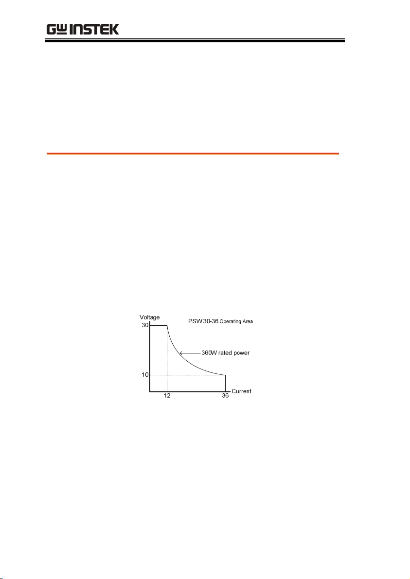
Operating Area Description
Description
The PSW power supplies are regulated DC
power supplies with a high voltage and current
output. These operate in CC or CV mode
within a wide operating range limited only by
the output power.
The operating area of each power supply is
determined by the rated output power as well
as the voltage and current rating. For example
the operating area and rated power output for
the PSW 30-36 is shown below.
When the power supply is configured so that
the total output (current x voltage output) is
less than the rated power output, the power
supply functions as a typical constant current,
constant voltage power supply.
20
If however, the power supply is configured
such that the total output (current x voltage
output) exceeds the rated power output, the
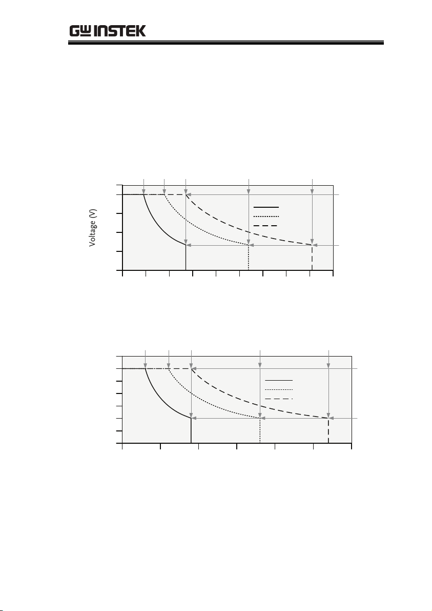
GETTING STARTED
effective output is actually limited to the power
limit of the unit. In this case the output current
and voltage then depend purely on the load
value.
Below is a comparison of the operating areas of
each power supply.
PSW 80V Series Operating Area
4.5 9.0 13.5
90
80
60
40
20
0
0
15
10
PSW 30V Series Operating Area
12 24 36
35
30
25
20
15
Voltage (V)
10
5
0
020
40
25
Current (A)
60
27 40.5
Type I
Type II
Type III
30
35
72 108
Type I
Type II
Type III
80
100
80
26.6
4540205
30
10
120
Current (A)
21

PSW Series User Manual
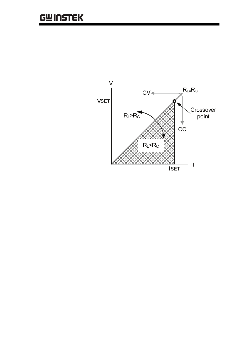
CC and CV Mode
CC and CV mode
Description
When the power supply is operating in
constant current mode (CC) a constant current
will be supplied to the load. When in constant
current mode the voltage output can vary,
whilst the current remains constant. When the
load resistance increases to the point where the
current limit (I
) can no longer be sustained
SET
the power supply switches to CV mode. The
point where the power supply switches modes
is the crossover point.
When the power supply is operating in CV
mode, a constant voltage will be supplied to
the load, whilst the current will vary as the
load varies. At the point that the load
resistance is too low to maintain a constant
voltage, the power supply will switch to CC
mode and maintain the set current limit.
The conditions that determine whether the
power supply operates in CC or CV mode
depends on the set current (I
(V
), the load resistance (RL) and the critical
SET
resistance (R
determined by V
). The critical resistance is
C
SET/ISET
. The power supply
), the set voltage
SET
will operate in CV mode when the load
resistance is greater than the critical resistance.
This means that the voltage output will be
equal to the V
less than I
voltage but the current will be
SET
. If the load resistance is reduced
SET
to the point that the current output reaches the
I
level, the power supply switches to CC
SET
mode.
22
GETTING STARTED
Conversely the power supply will operate in
CC mode when the load resistance is less than
the critical resistance. In CC mode the current
output is equal to I
less than V
SET
.
and the voltage output is
SET
23
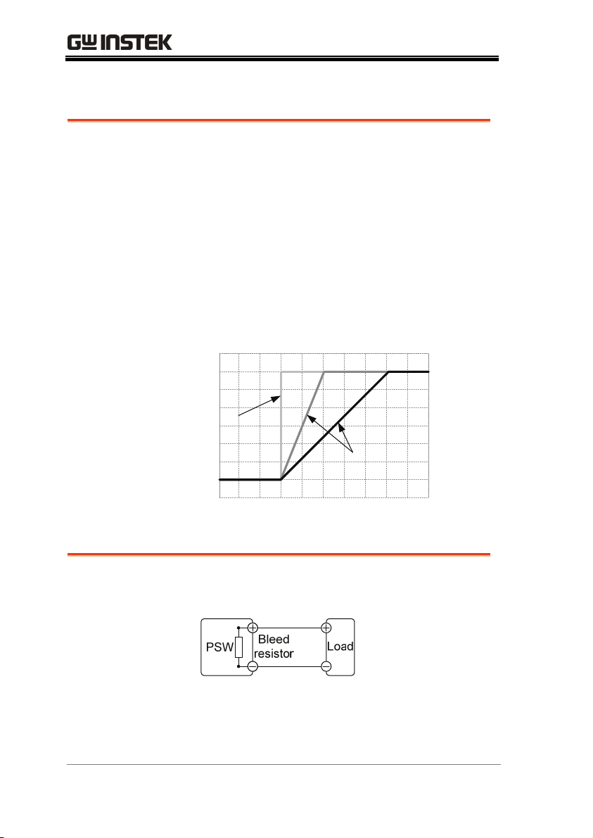
Slew Rate
PSW Series User Manual
Theory
Bleeder Control
The PSW has selectable slew rates for CC and
CV mode. This gives the PSW power supply
the ability to limit the current/voltage draw of
the power supply. Slew rate settings are
divided into High Speed Priority and Slew
Rate Priority. High Speed Priority mode
disables slew rate settings for CC or CV mode.
Slew Rate Priority mode allows for user
adjustable slew rates for CC or CV mode. The
rising and falling slew rate can be set
independently.
Slew rate=
Disabled
Slew rate =
Enabled
Description
The PSW DC power supplies employ a bleed
resistor in parallel with the output terminals.
Bleed resistors are designed to dissipate the
power from the power supply filter capacitors
when power is turned off and the load is
disconnected. Without a bleed resistor, power
24

GETTING STARTED
may remain charged on the filter capacitors for
some time and be potentially hazardous.
In addition, bleed resistors also allow for
smoother voltage regulation of the power
supply as the bleed resistor acts as a minimum
voltage load.
The bleed resistance can be turned on or off
using the configuration settings.
Note
Internal Resistance
Description
Internal
Resistance Range
By default the bleed resistance is on. For battery
charging applications, be sure to turn the bleed
resistance off as the bleed resistor can discharge
the connected battery when the unit is off.
On the PSW, the internal resistance of the
power supply can be user-defined in software.
(Internal Resistance Setting, page 78). When the
internal resistance is set it can be seen as a
resistance in series with the positive output
terminal. This allows the power supply to
simulate power sources that have internal
resistances such as lead acid batteries.
Unit Model
PSW 30-36
PSW 30-72
PSW 30-108
PSW 80-13.5
PSW 80-27
PSW 80-40.5
Internal Resistance Range
0.000 ~ 0.833Ω
0.000 ~ 0.417Ω
0.000 ~ 0.278Ω
0.000 ~ 5.926Ω
0.000 ~ 2.963Ω
0.000 ~ 1.975Ω
25

PSW Series User Manual
Alarms
The PSW power supplies have a number of protection features.
When one of the protection alarms are set, the ALM icon on the
display will be lit. For details on how to set the protection modes,
please see page 43.
OVP
Overvoltage protection (OVP) prevents a high
voltage from damaging the load.
OCP
Overcurrent protection prevents high current
from damaging the load.
OTP
Over temperature protection protects the
instrument from overheating.
Power Switch Trip
When the Power Switch Trip configuration
setting is enabled, the power supply will
automatically shut down when a protection
setting has been tripped (OCP, OVP, OTP).
Alarm output
Alarms are output via the analog control
connector. The alarm output is an isolated
open-collector photo coupler output.
Considerations
The following situations should be taken into consideration when
using the power supply.
Inrush current
26
When the power supply switch is first turned
on, an inrush current is generated. Ensure there
is enough power available for the power
supply when first turned on, especially if a
number of units are turned on at the same
time.
GETTING STARTED
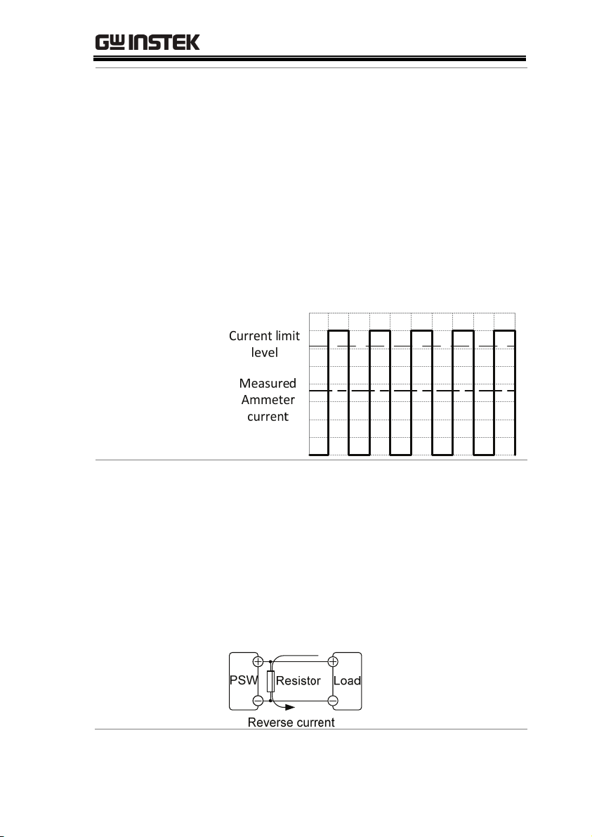
Pulsed or Peaked
loads
Reverse Current:
Regenerative load
When the load has current peaks or is pulsed, it
is possible for the maximum current to exceed
the mean current value. The PSW power
supply ammeter only indicates mean current
values, which means for pulsed current loads,
the actual current can exceed the indicated
value. For pulsed loads, the current limit must
be increased, or a power supply with a greater
capacity must be chosen. As shown below, a
pulsed load may exceed the current limit and
the indicated current on the power supply
ammeter.
When the power supply is connected to a
regenerative load such as a transformer or
inverter, reverse current will feed back to the
power supply. The PSW power supply cannot
absorb reverse current. For loads that create
reverse current, connect a resistor in parallel to
the power supply to bypass the reverse
current. This description only applies when the
bleed resistance is off.
27
PSW Series User Manual
Note
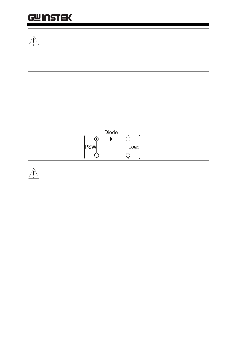
Reverse Current:
Accumulative
energy.
CAUTION
The current output will decrease by the amount of
current absorbed by the resistor.
Ensure the resistor used can withstand the power
capacity of the power supply/load.
When the power supply is connected to a load
such as a battery, reverse current may flow
back to the power supply. To prevent damage
to the power supply, use a reverse-currentprotection diode in series between the power
supply and load.
Ensure the reverse withstand voltage of the diode
is able to withstand 2 times the rated output
voltage of the power supply and the forward
current capacity can withstand 3 to 10 times the
rated output current of the power supply.
28
Ensure the diode is able to withstand the heat
generated in the following scenarios.
When the diode is used to limit reverse voltage,
remote sensing cannot be used.
GETTING STARTED
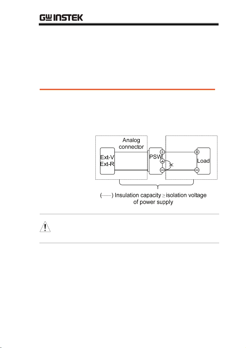
Grounding
The output terminals of the PSW power supplies are isolated with
respect to the protective grounding terminal. The insulation
capacity of the load, the load cables and other connected devices
must be taken into consideration when connected to the protective
ground or when floating.
Floating
WARNING
As the output terminals are floating, the load
and all load cables must have an insulation
capacity that is greater than the isolation
voltage of the power supply.
If the insulation capacity of the load and load
cables is not greater than the isolation voltage of
the power supply, electric shock may occur.
29
PSW Series User Manual
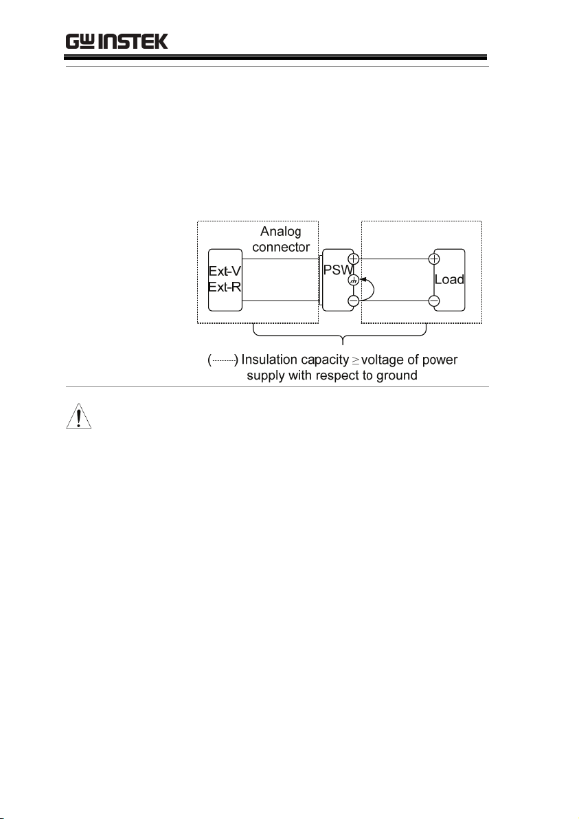
Grounded output
terminal
CAUTION
If the positive or negative terminal is connected
to the protective ground terminal, the
insulation capacity needed for the load and
load cables is greatly reduced. The insulation
capacity only needs to be greater than the
maximum output voltage of the power supply
with respect to ground.
If using external voltage control, do not ground
the external voltage terminal as this will create a
short circuit.
30
Loading…
100% официальная поставка
Элиз — официальный дилер
Good Will Instrument Co., Ltd. (GW Instek, Тайвань)
поставщика SPS-3610
Благодарственное письмо, отзыв от ОАО «Аэрофлот»
г. Москва
Все отзывы
7 фактов о компании «Элиз»
- Успешно работаем с 2000 года.
- Нам доверяют больше 7500 предприятий и организаций со всей России.
- Мы являемся официальным представителем свыше 100 компаний-производителей.
- Предоставляем специальные цены на крупные партии и тендеры.
- Доставляем товары по всей России — это более 1000 городов и населенных пунктов.
- Гарантируем 100% выполнение своих обязательств.
- Оказываем информационную поддержку своим клиентам.
специальное предложение
|
|
36 540 руб. с НДС c Заказать в один клик Безналичный расчет Работаем только с юридическими лицами и ИП. Доставка по всей России бесплатная доставка до терминала транспортной компании в вашем городе при заказе от 100 000 руб. |
||||||||||||||||||||||||||||||||||||||||||||||||||||||||||||||||||||||
|
|||||||||||||||||||||||||||||||||||||||||||||||||||||||||||||||||||||||
|
Особенности Описание Спецификация Комплектация Файлы
Описание Источника питания постоянного тока импульсный SPS-3610
Технические характеристики источника питания SPS-3610
Комплектация источника питания SPS-3610
Технические параметры (спецификация) и комплект поставки товара могут быть изменены производителем без предварительного уведомления. Информация носит справочный характер и не является публичной офертой, определяемой положениями Статьи 437 Гражданского кодекса Российской Федерации. Документы, файлы, паспорт, инструкция SPS-3610
В описании ошибка? Выделите её и нажмите Ctrl + Enter
Возникли вопросы? Звоните, пишите — мы вам поможем!
|
| Купить SPS-3610 — импульсный источник питания постоянного тока GW Instek (SPS3610) | Цена: 36 540 руб. с НДС. |
|