
EZ2250i/EZ2350i BARCODE PRINTER
USER MANUAL
User Manual
Version
Issue Date
P/N
: EZ2250i series
: Rev. E
: 2013.11.28
: 920-014611-00
1

EZ2250i/EZ2350i USER MANUAL
CONTENTS
. BOX CONTENT ………………………………………………………………….
1.1 Box Content …………………………………………………………………………………………………
1.2 Getting to Know Your Printer ……………………………………………………………………….
. PRINTER SETUP …………………………………………………………………..
2-1. Loading the label roll ………………………………………………………………………………………
2-2. Loading the ribbon………………………………………………………………………………………….
2-3. Connecting the printer to the host computer ………………………………………………….
2.4 Installing Printer Driver and GoLabel with Super Wizard CD …………………………..
. PRINTER SETTING AND CONTROL ……………………………………… 1
3-1. Operation Panel …………………………………………………………………………………………… 14
3-2. LCD Interface Introduction …………………………………………………………………………… 15
3-3 LAN Setting ……………………………………………………………………………………………………. 20
3-4 LCD Password ……………………………………………………………………………………………….. 22
3-5. LCD Interface Function …………………………………………………………………………………. 24
3-6. Label Calibration and Self Test ……………………………………………………………………… 28
3-7. Dump mode …………………………………………………………………………………………………. 30
3-8. Error Alerts …………………………………………………………………………………………………….. 31
3-9. USB Host ……………………………………………………………………………………………………….. 33
. NETSETTING FOR ETHERNET ………………………………………………. 3
4-1. Installing the NetSetting software ………………………………………………………………….. 35
4-2. The Interface of NetSetting …………………………………………………………………………… 36
. ACCESSORIES ………………………………………………………………… 4
5-1. Internal rewinder …………………………………………………………………………………………… 43
5-2. Installing the rewinder guide …………………………………………………………………………. 45
5-3. Label dispenser …………………………………………………………………………………………….. 46
5-4. Installing the cutter ……………………………………………………………………………………….. 48
5-5. Installing the Parallel adapter ……………………………………………………………………….. 50
. MAINTENANCE AND ADJUSTMENT …………………………………… 5
6-1. Installing / removing the print head module …………………………………………………. 52
6-2. Adjusting the print line ………………………………………………………………………………….. 53
6-3. Adjusting the ribbon tension …………………………………………………………………………. 54
6-4. Cleaning the thermal print head ………………………………………………………………….. 55
6-5. Adjusting the balance and print head tension ……………………………………………… 56
6-6. Ribbon shield settings ……………………………………………………………………………………. 57
6-7. Cutter settings ………………………………………………………………………………………………. 58
6-8. Troubleshooting ……………………………………………………………………………………………. 59
PPENDIX
Contents

EZ2250i/EZ2350i USER MANUAL
FCC COMPLIANCE STATEMENT
FOR AMERICAN USERS
This equipment has been tested and found to comply with the limits for a CLASS A digital device,
pursuant to Part 15 of the FCC Rules. These limits are designed to provide reasonable protection
against harmful interference when the equipment is operated in a commercial environment. This
equipment generates, uses, and can radiate radio frequency energy and, if not installed and used
in accordance with the instructions, may cause harmful interference to radio communications.
Operation of this equipment in a residential area is likely to cause harmful interference in which case
the user will be required to correct the interference at own expense.
EMS AND EMI COMPLIANCE STATEMENT
FOR EUROPEAN USERS
This equipment has been tested and passed with the requirements relating to electromagnetic
compatibility based on the standards EN 55022:2010 Class A, EN61000-3-2:2006/ A1:2009/A2:2009,
EN 61000-3-3:2008 and EN 55024:2010, IEC 61000-4-2:2008 series The equipment also tested and
passed in accordance with the European Standard EN55022 for theboth Radiated and
Conducted emissions limits.
EZ2250i SERIES
TO WHICH THIS DECLARATION RELATES
IS IN CONFORMITY WITH THE FOLLOWING STANDARDS
IEC 60950-1:2005(2nd Edition)+Am 1:2009, GB4943-2001 GB9254-2008(Class A) GB17625.1-2003,
EN 55022:2010 Class A, EN61000-3-2:2006/ A1:2009/A2:2009, EN 61000-3-3:2008 and EN 55024:2010,
IEC 61000-4-2:2008 series, CAN/CSA C22.2 No. 60950-1-03, date July, 2006, UL 60950-1, 1st Edition,
2007-10-31, CFR 47, Part 15
WARNING
This is a Class A product. In a domestic environment this product may cause radio interference
in which case the user may be required to take adequate measures.
此为Class A产品,在生活环境中,该产品可能造成无线电干扰,在这种情况下,可能需要用户对其干扰采取切实可行
的措施。
Decleration

EZ2250i/EZ2350i USER MANUAL
SAFETY INSTRUCTIONS
Please read the following instructions carefully.
1. Keep the equipment away from humidity.
2. Before you connect the equipment to the power outlet, please
check the voltage of the power source.
3. Make sure the printer is off before plugging the power connector
into the power jack.
4. It is recommended that you connect the printer to a surge
protector to prevent possible transient overvoltage damage.
5. Be careful not to get liquid on the equipment to avoid electrical
shock.
6. For safety and warranty reasons, ONLY qualified service personnel
should open the equipment.
7. Do not repair or adjust energized equipment under any
circumstances.
Caution
**** Danger of explosion if battery is incorrectly replaced. Replace only with the equivalent type recommended by
the manufacturer.
**** Dispose of used batteries according to the manufacturer’s instructions.
**** Only use with designated power supply adapter model.
**** Changes or modifications not expressly approved by the party responsible for compliance could void the user’s
authority to operate the equipment.
Specifications are subject to change without notice.
Safety instructions
1 Barcode Printer
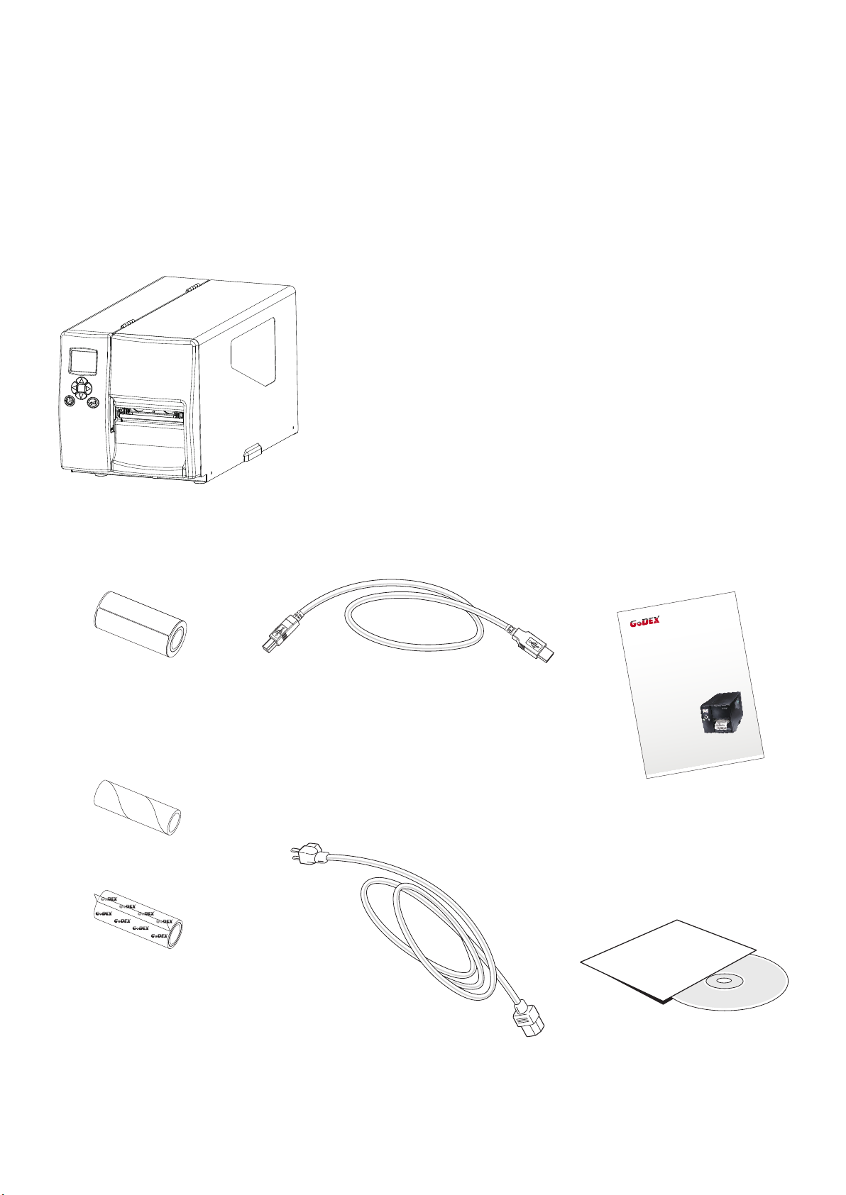
1.1 Box Content
Please check that all of the following items are included with your printer.
EZ2250i/EZ2350i Barcode Printer
Label Stock
Ribbon Module
Empty Ribbon Core
Ribbon
USB Cable
Power Adapter
Power Cord
EZ2250i Series Quick Guide
EZ2250i/EZ2350i Series
CD
Including GoLabel software
and EZ2250i/EZ2350i user manual.
1
1 Barcode Printer
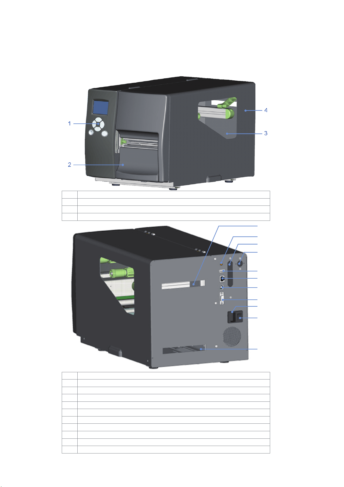
Feed slot for continuous labels
Applicator interface (optional)
Feed slot for continuous labels
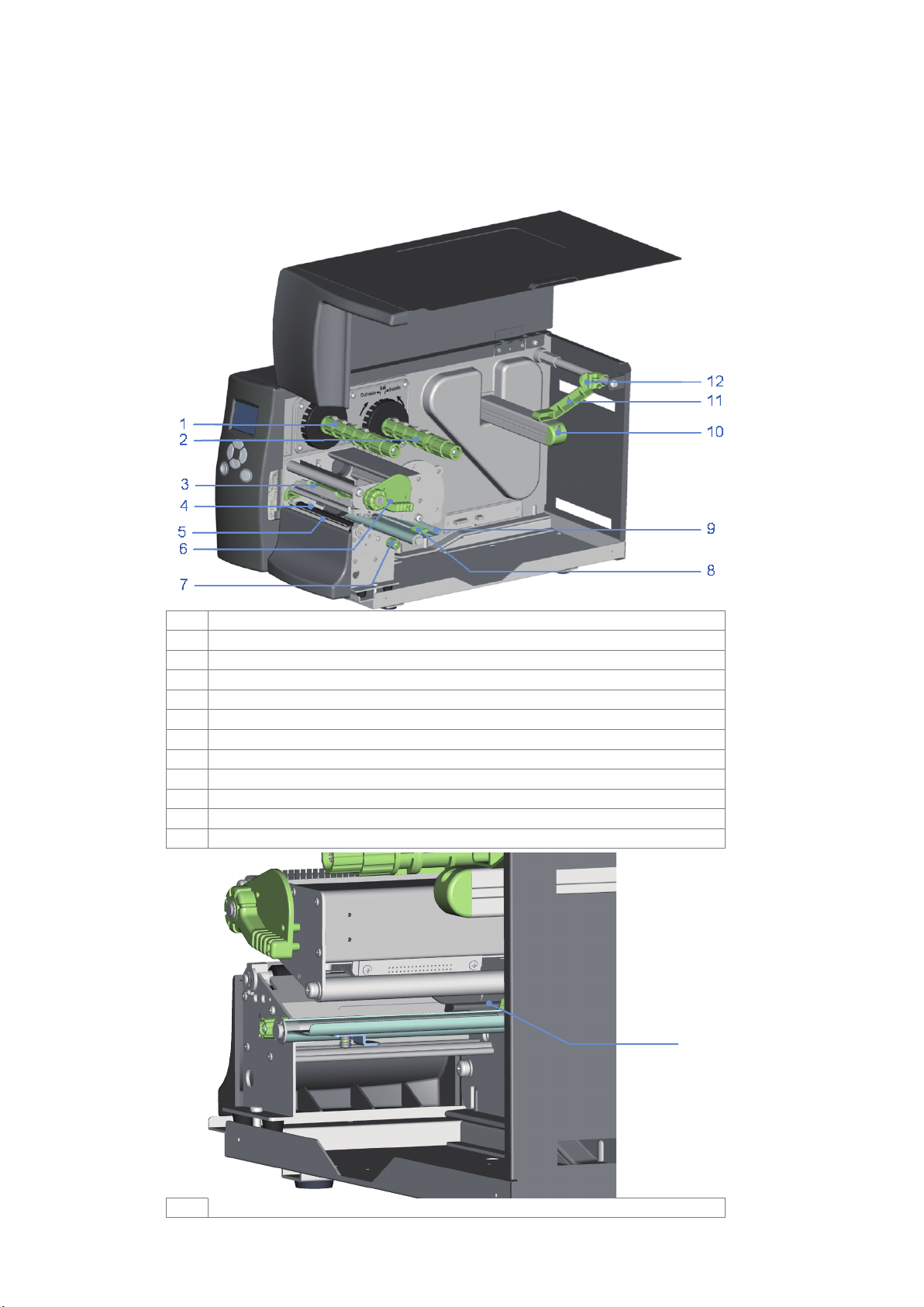
1.2 Getting to Know Your Printer
External view
1
2
3
4
5
6
7
8
9
10
11
2
1 Barcode Printer
Release lever for print head
Adjustment wheel for sensor
1
3
2 Printer Setup
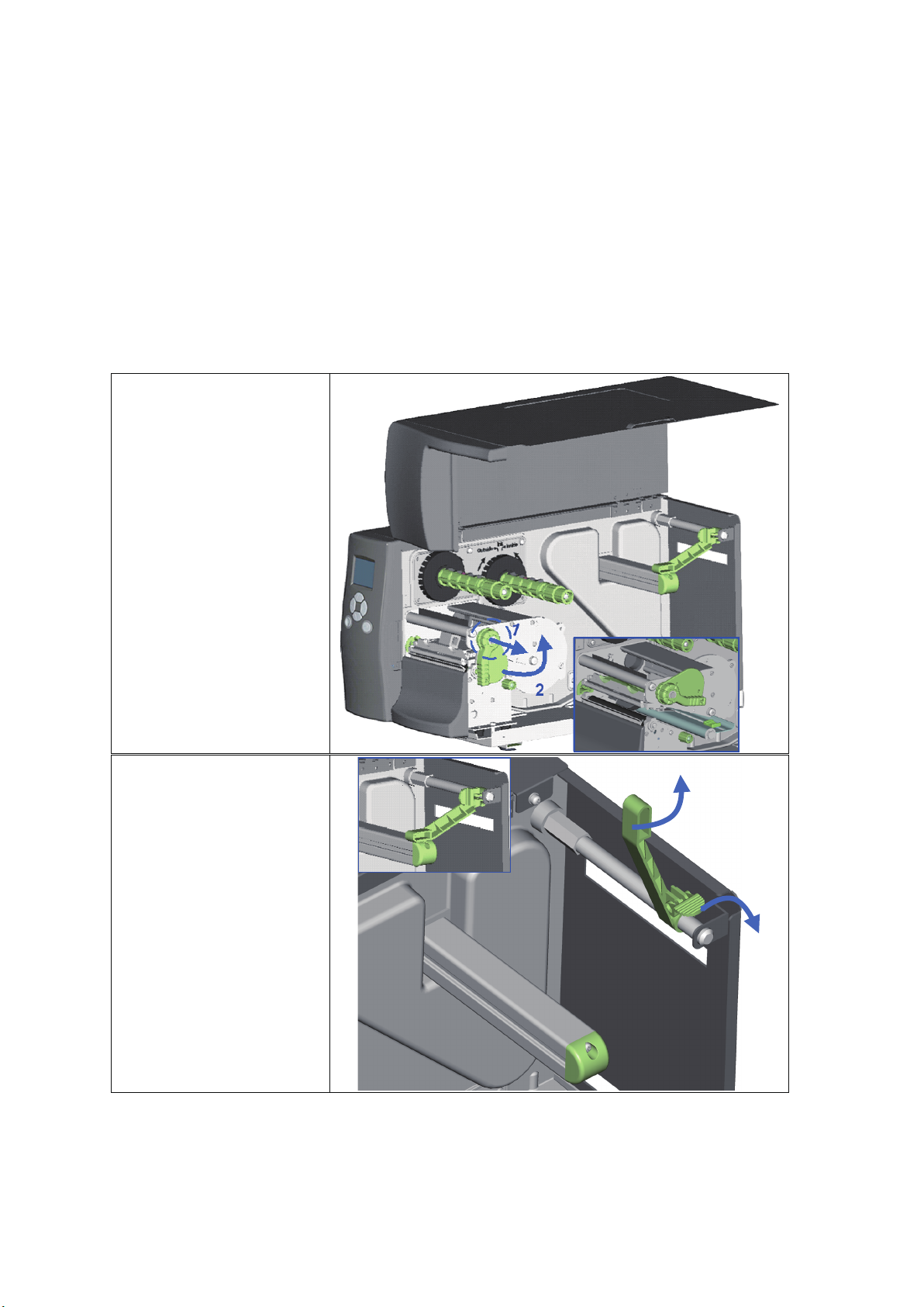
1. Place the printer on a
3. Pull the release catch
2.1 Loading the label roll
This printer supports the following printing methods:
Thermal transfer printing (TTP):Requires a ribbon for transferring a printed image to a medium.
Direct thermal printing (DTP):Does not require a ribbon, only thermal paper.
Please check which printing method you are using and alter the settings accordingly in the printer driver,
printer menu, and/or software.
flat surface and open
the printer cover.
2. Pull out the print
head release lever as
shown in the
illustration (1) and
turn it anticlockwise
to a top right position
(2).
for the label roll guide
to the right as shown
by the blue arrow 1.
4. Now slide the label
roll guide forward
and fold it up as
shown by the blue
arrow 2.
2
1
4
2 Printer Setup
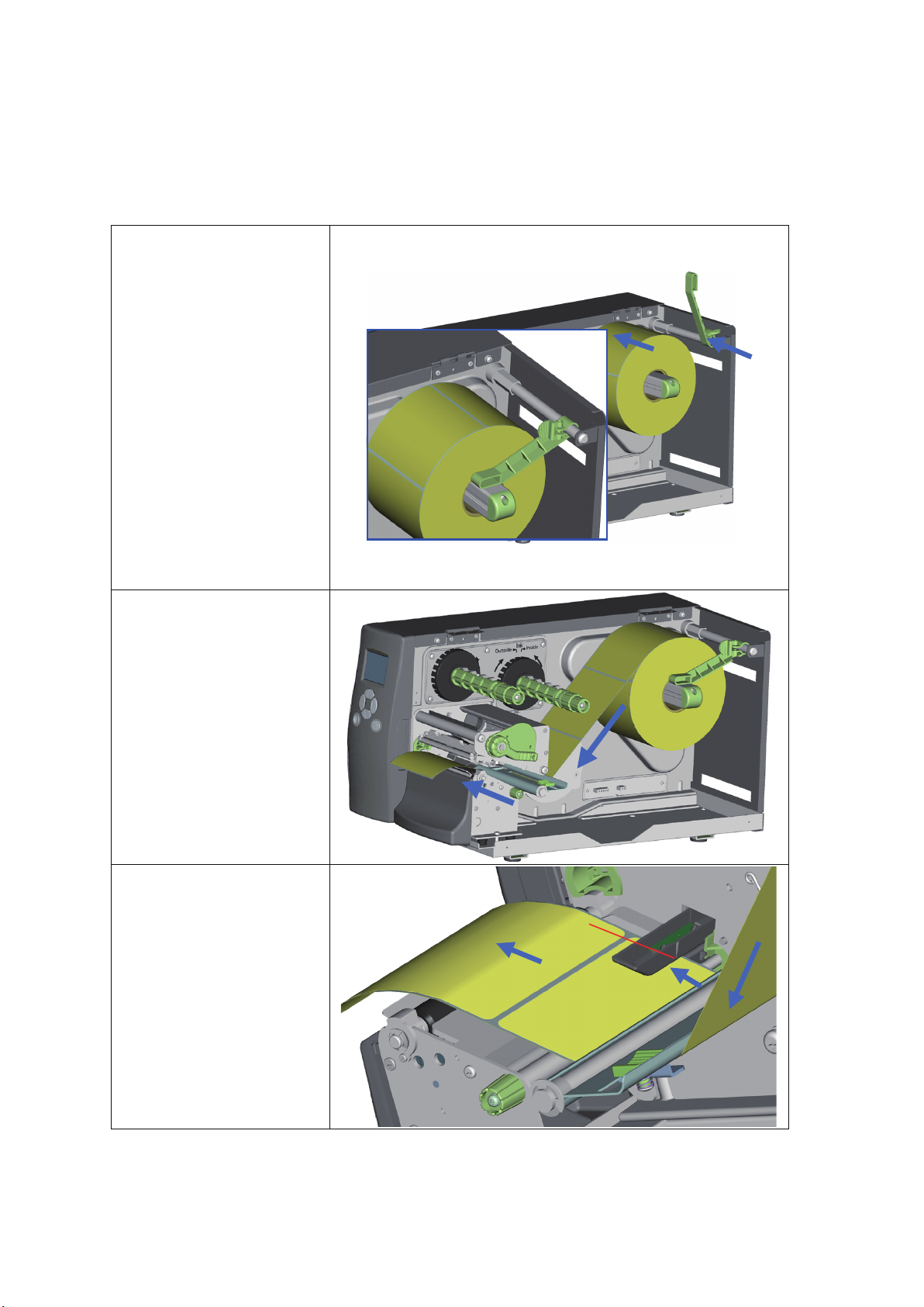
5. Place the label roll on
the bracket, not by its top.
the label supply hub,
pushing it right up to
the printer housing.
(Do not apply too
much pressure to
avoid damaging the
label stock.)
6. Fold the label roll
guide back down
and push it against
the label roll.
Note】
【
When moving the label roll
guide, hold it only by the
end that is attached to
into the printer as
shown in the
illustration. Pass it
through the printer as
indicated by the blue
arrows.
through the sensor
and up to the tear-off
plate.
Note】
【
Remember to set the
movable sensor to gap,
black mark, or tag hole by
changing the position of
the sensor with the
adjustment wheel.
3
1
2
5
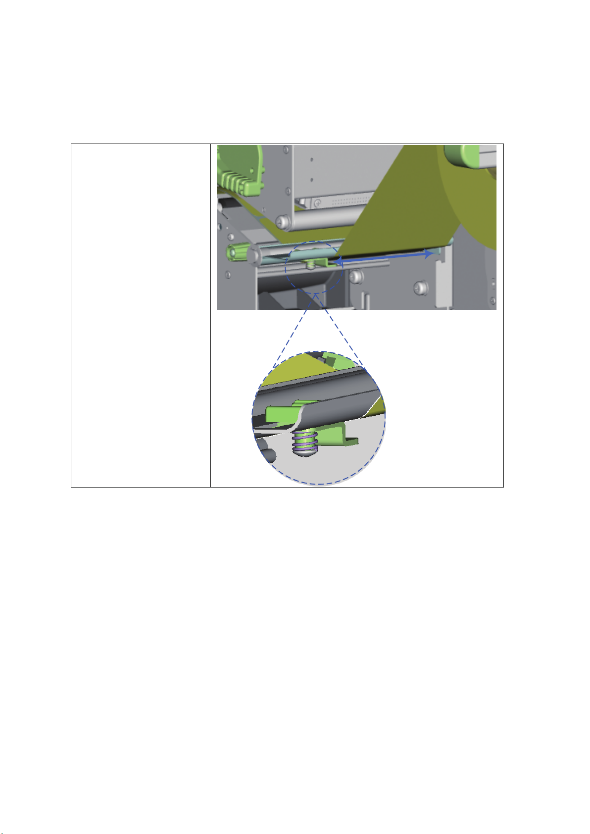
2 Printer Setup
between the wall of
the printer housing
and the adjustable
paper guide.
Note】
【
Pass the labels through the
printer as shown in the
illustration.
10. Return the print head
release lever to its
original position.
11. Then close the printer
cover.
6
2 Printer Setup
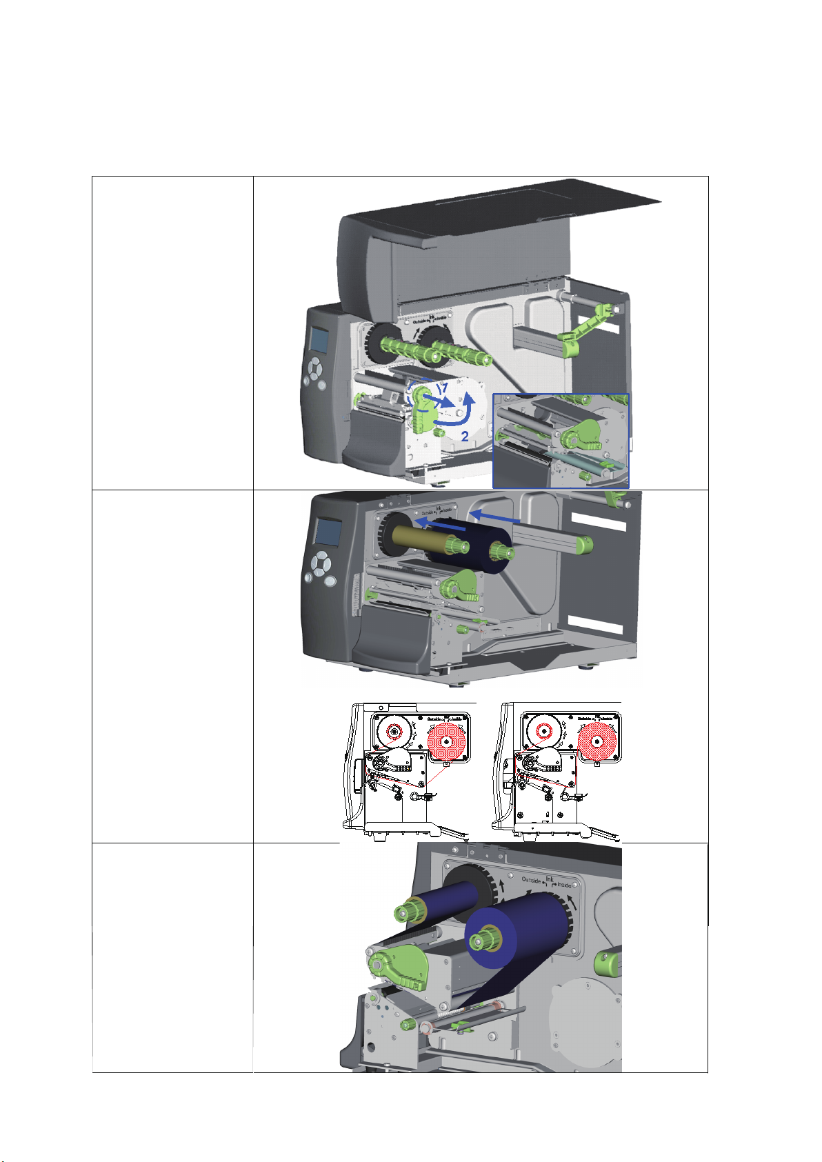
2.2 Loading the Ribbon
on a flat surface
and open the
printer cover.
2. Pull out the print
head release
lever as shown in
the illustration (1)
and turn it
anticlockwise to a
top right position
(2).
4. The two
Note】
【
Do not pass the
ribbon under the
sensor.
ribbon on the
ribbon supply
hub. Then place
an empty ribbon
core on the
ribbon rewind
hub.
illustrations on the
right show you
how to install the
ribbon
depending on
the ribbon type
(ink side in or out).
under the print
head and back
up on the other
side. Attach it to
the empty ribbon
core.
7
2 Printer Setup
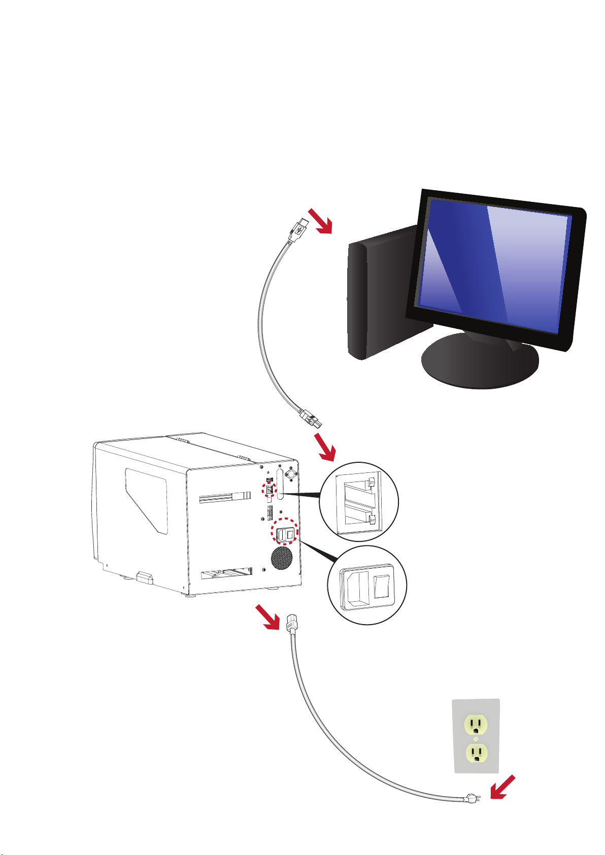
2.3 Connecting the Printer to the Host Computer
1. Please make sure that the printer is switched off.
2. Connect the power cord to the AC adapter and connect the adapter to the printer.
3. Connect the USB cable to the printer and host computer.
4. Switch on the printer. The operator panel should now light up.
8
2 Printer Setup
2.4
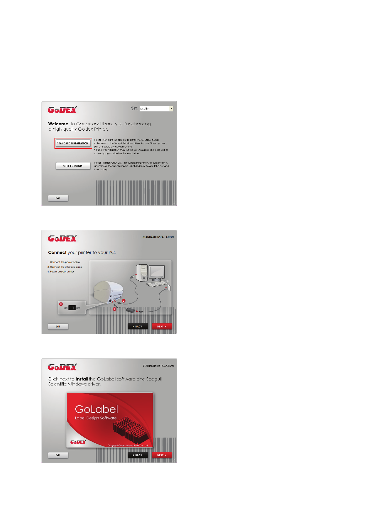
1. Insert the Super Wizard CD in the CD/DVD drive of the host computer and the program should pop up
automatically.
You will see the Welcome screen first. On the Welcome screen, choose “Standard Installation”.
2. The wizard will then ask you to make sure your USB and power cables are connected and that the power is
turned on. Make sure that is done and then click “Next”.
Installing Printer Driver and GoLabel with Super Wizard CD
3. The next screen you will see is, “Install the GoLabel Software and Windows driver”. Click “Next” to continue.
Notice
* If the Super Wizard program did not run automatically, you can either turn on the “Auto-run” setting for your
CD/DVD driver or double-click the icon of CD/DVD driver to run the program.
9
2 Printer Setup
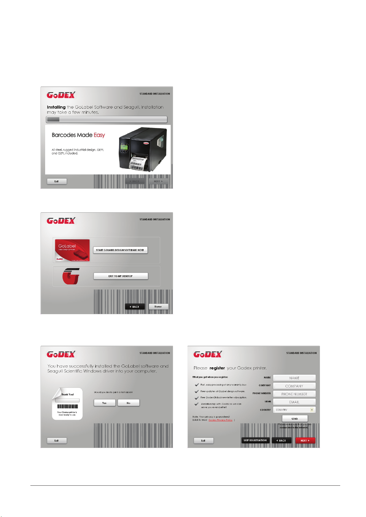
4. As the printer driver and GoLabel are installing, a screen will display a progress bar.
5. Once the installation is complete, you can start to make and print labels with GoLabel or throug the printer driver.
6. As the optional steps, you can also print a test label or register your printer during the “Standard Installation”
procedure.
Notice
* If you need more resources, tools or reference documents, you can also find them on Super Wizard CD.
Just click “Other Choices” on Welcome Screen to access the files.
10
2 Printer Setup
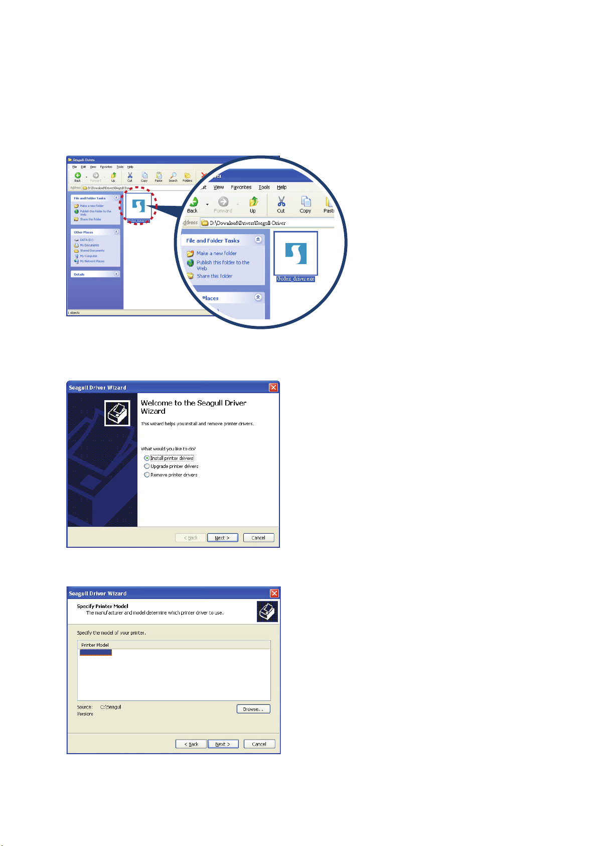
Installing Printer Driver Directly from CD Folder
1. Insert the product CD in the CD/DVD drive of the host computer and open the «Seagull Drivers» folder on the CD.
Select the icon for the driver file and click it to start the installation.
2. Follow the instructions on the screen. The Driver Wizard guides you through the installation procedure.
Select «Install printer drivers».
3. Specify your printer model.
Godex EZ2250i
11
2 Printer Setup2 Printer Setup
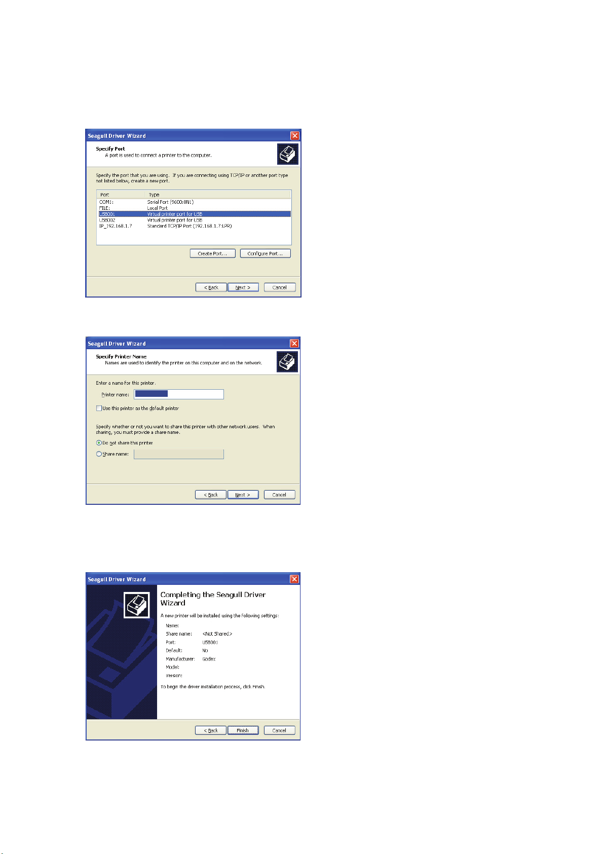
4. Specify the port used to connect the printer to the host computer.
5. Enter a printer name and assign the appropriate rights.
Godex EZ2250i
Godex EZ2250i
6. Once the installation is complete, a summary of the printer settings is displayed.
Check whether the printer settings are correct and click «Finish» to start copying the driver files.
Wait until copying is complete, then finish the installation.
Godex EZ2250i
Godex EZ2250i
12
2 Printer Setup
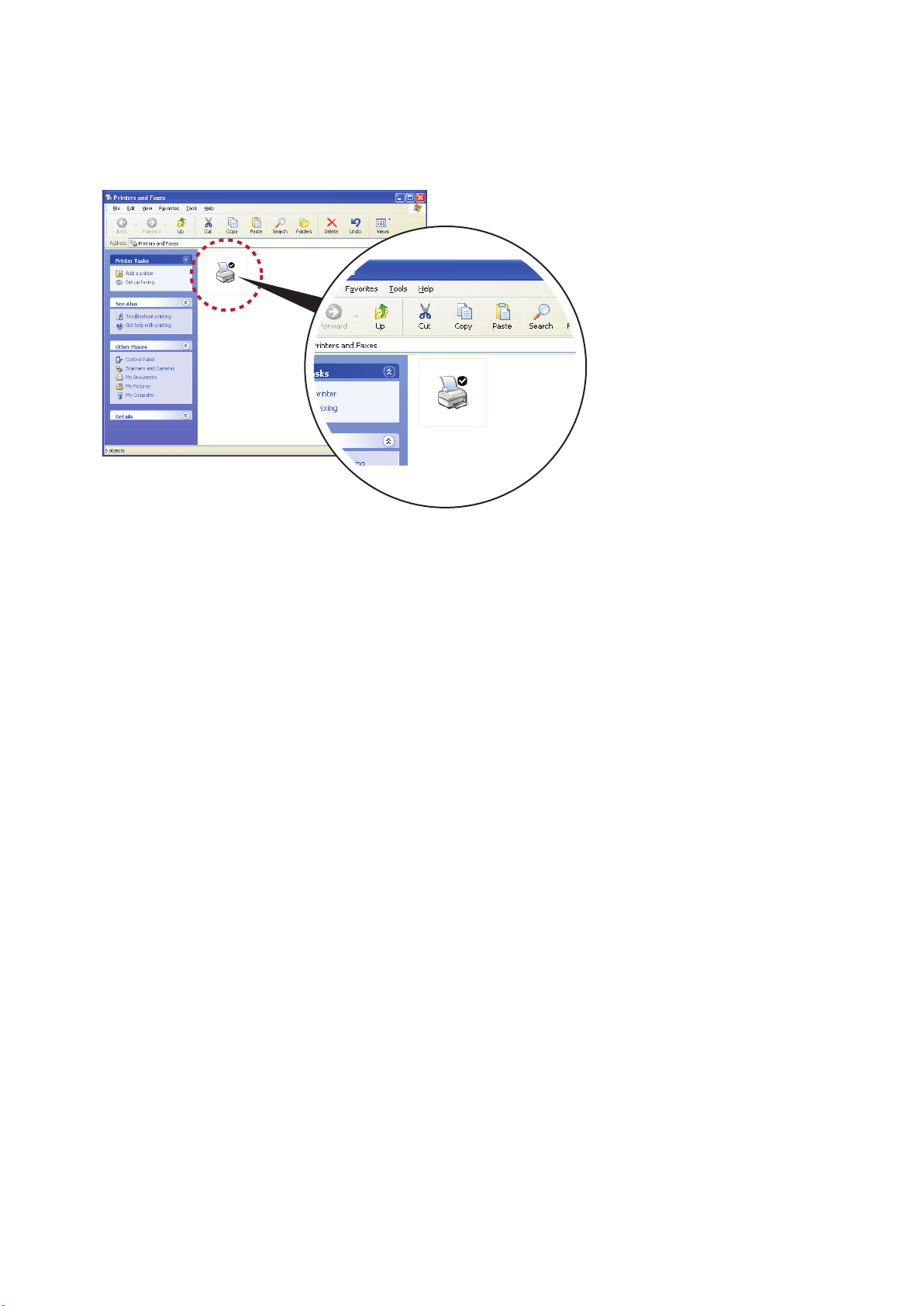
7. Once the driver installation is complete, the new printer should appear in the «Printers and Faxes» folder.
Godex EZ2250i
Godex EZ2250i
13
3 Printer Setting and Control
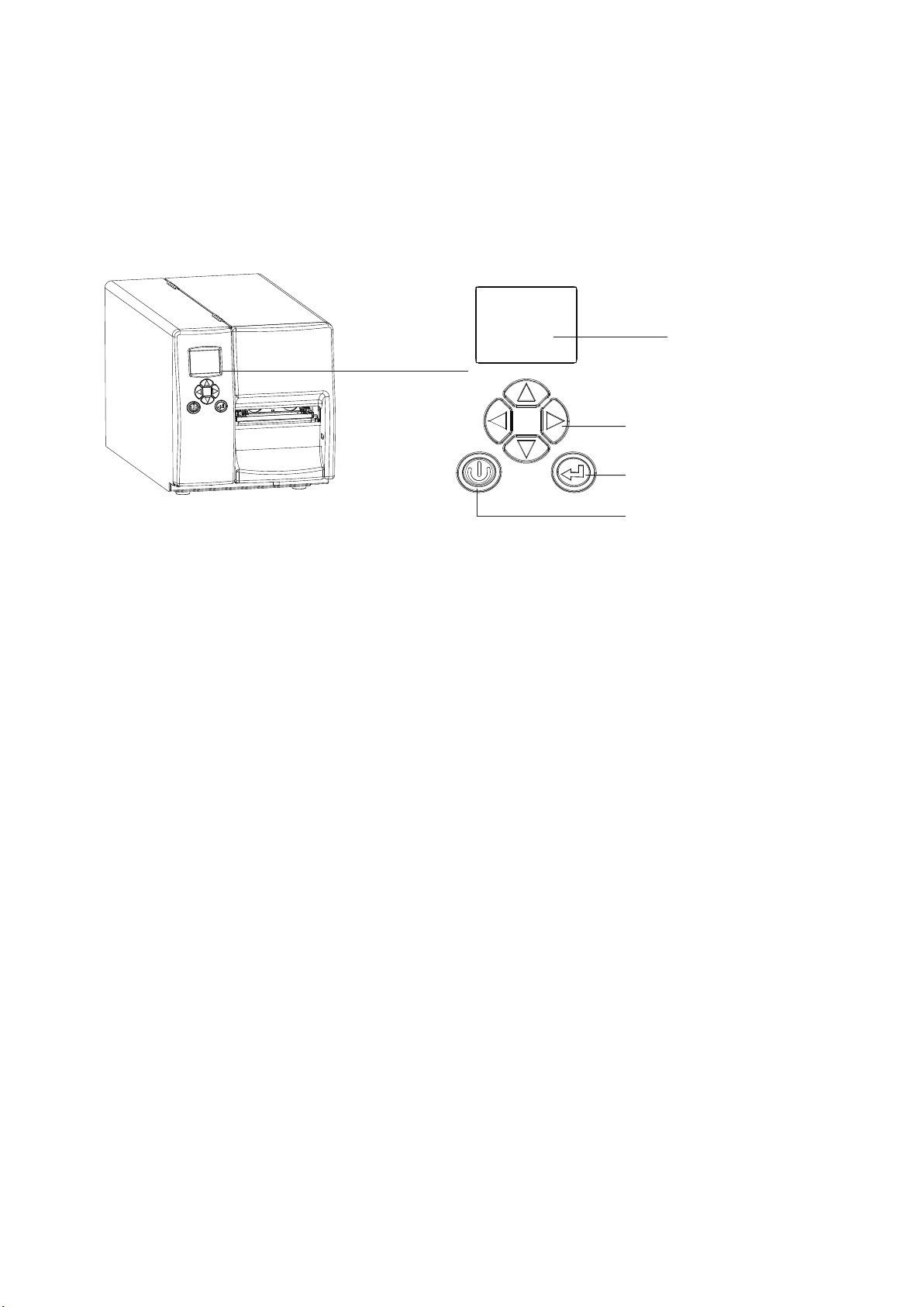
3.1 Operation Panel
Operation Panel Introduction
OPERATION PANEL
LCD SCREEN
DIRECTION KEY
FEED BUTTON
POWER BUTTON
POWER Button
Press the POWER button to turn on the printer, and the START UP SCREEN appears. The printer is on “ready to print”
status, the LCD screen should display the message “READY“ on the screen.
When printer is turned on, keep pressing the POWER button for 3 second will turn the printer off.
FEED Button
When you press the FEED button, the printer moves the label to the defined stop position.
If you are using continuous labels, pressing the FEED button will move label stock until you release the button again.
If you are using individual labels, pressing the FEED button will move only one label.
If the label does not stop at the correct position, you need to run the auto-detection function on the label stock, please see Section 3.6 Label
Calibration and Self Test.
PAUSE PRINTING_FEED Button
Pressing the FEED button while the printer is in standby mode will set the printer to pause mode. In this mode,
the printer can receive commands, but it can only process them when it is reset to standby mode. Pressing the
FEED button again will reset the printer to standby mode.
Pressing the FEED button during printing will interrupt printing. When the PFEED button is pressed again, the printer
resumes printing. Example: While a 10-label print job is running, you press the FEED button to pause the printer.
Two of the labels have been printed. To resume printing and print the remaining eight labels, you press the
FEED button again.
CANCEL PRINTING_FEED Button
Pressing the FEED button over 3 seconds during printing cancels a print job. The current print job is cancelled.
Example: While a 10-label print job is running, you press the FEED button. Two of the labels have been printed.
The print job is cancelled and the remaining eight labels are not printed.
14
3 Setting and Control for Operation Panel
3.2 LCD Interface Introduction
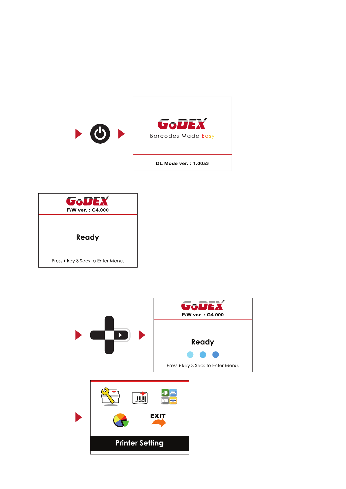
Getting Started
Press the POWER button to turn on the printer, and the START UP SCREEN appears.
Power on
If the printer is on “ready to print” status, the LCD screen should display the message “Ready“ on the screen.
Please keep pressing button and wait for the timer to be filled, then the LCD interface will enter into the MAIN
PAGE for SETTING MODE. You can make various setting functions in SETTING MODE.
Enter Main page
15
3 Setting and Control for Operation Panel
Operations on Setting Page
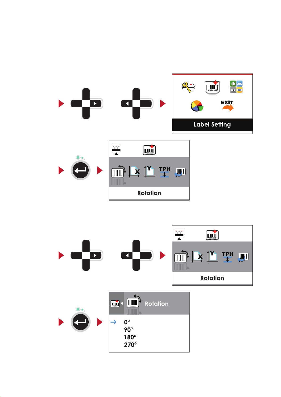
On MAIN PAGE, press or button to move the cursor and select the functions.
Select a designated function and press FEED button, you will enter the SETTING PAGES for the function.
Select
Enter
On SETTING PAGES, press or button to select the setting items.
Select a designated function and press FEED button, you will enter the SETTING VALUE PAGES for the function.
or
Select
Enter
or
16
3 Setting and Control for Operation Panel
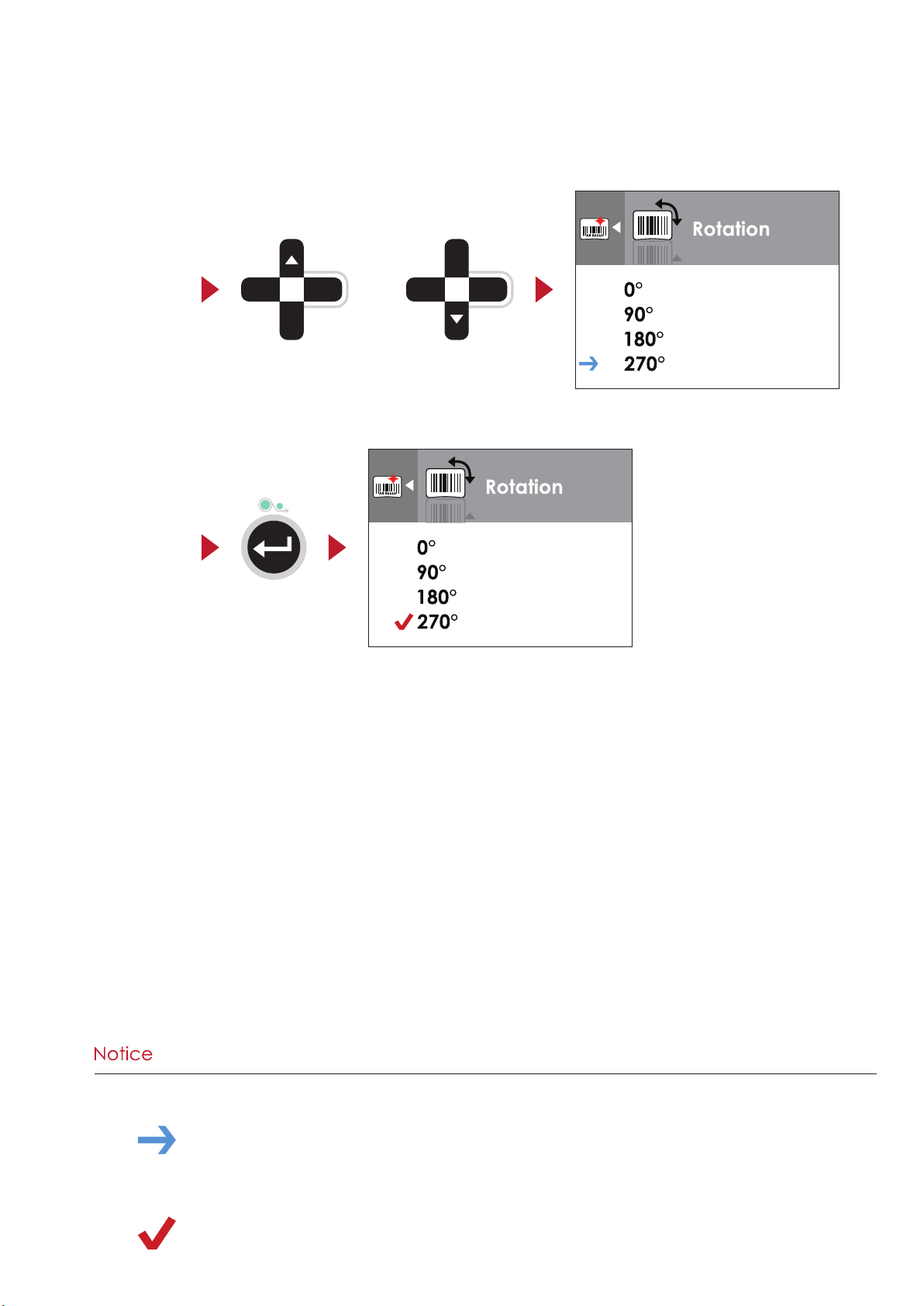
On SETTING VALUE PAGES, press or button to change the setting values.
Select
Press FEED button will apply the setting value you just selected, and the red tick will appear to mark the value.
Apply
or
**** The blue arrow indicates the value you are selected.
**** The red tick indicates that the selected value is applied now.
17
Loading…
-
Page 1
1 EZ2250i/EZ2350i BARCODE PRINTER USER MANUAL User Manual Version Issue Date P/N : EZ2250i series : Rev. E : 2013.11.28 : 920-014611-00[…]
-
Page 2
Contents EZ2250i/EZ2350i USER MANUAL CONTENTS Contents 1 . BOX CONTENT ……… ….. ….. …. ….. …. …. ….. ….. …. ….. ….. …. …. ….. … 1 1.1 Box Content ………………………….. ………………………….. ……………………………………….. 1 1.2 Getting t o Know Your Print er ………………[…]
-
Page 3
EZ2250i/EZ2350i USER MANUAL FCC COMPLIANCE STATEMENT FOR AMERICAN USERS This equipment has been tested and found to comply with the limits for a CLASS A digital device, pursuant to Part 15 of the FCC Rules. These limits are designed to provide reasonable protection against harmful interference when the equipment is operated in a commercial environm[…]
-
Page 4
EZ2250i/EZ2350i USER MANUAL SAFETY INSTRUCTIONS Please read the following instructions carefully. 1. Keep the equipment away from humidity. 2. Before you connect the equipment to the power outlet, please check the voltage of the power source. 3. Make sure the printer is off before plugging the power connector into the power jack. 4. It is recommend[…]
-
Page 5
1 1 Barcode Printer 1.1 Box Content Please check that all of the following items are included with your printer. EZ2250i/EZ2350i Barcode Printer USB Cable CD Including GoLabel software and EZ2250i/EZ2350i user manual. Label Stock Ribbon Module Empty Ribbon Core Ribbon Power Adapter Power Cord EZ2250i Series Quick Guide E[…]
-
Page 6
2 1 Barcode Printer 1.2 Getting to Know Your Printer External view 1. Operator panel 2. Lower cover plat e 3. Viewing win dow 4. Printer cover 1. Feed slot for cont inuous lab els 2. Auto-Calibra tion button 3. Parallel port (optional) 4. Applicator int erface (optional) 5. USB Host 6. N Ethernet p ort 7. USB port 8. Serial port (DB-9) 9. Power jac[…]
-
Page 7
3 1 Barcode Printer Internal view 1. Ribbon rewin d hub 2. Ribbon supply hub 3. Print mecha nism 4. Platen roller 5. Tear-off plate 6. Release lever for print head 7. Adjustment wheel for sensor 8. Paper guide 9. Label tension guide 10. Label supply hub 11. Label roll guide 12. Release catch 1. Movable sensor 1[…]
-
Page 8
4 2 Printer Setup This printer supports the following printing methods: Thermal transfer printing (TTP) : Requires a ribbon for transferring a printed image to a medium. Direct thermal printing (DTP) : Does not require a ribbon, only thermal paper. Please check which printing method you are using and alter the settings accordingly in the printe[…]
-
Page 9
5 2 Printer Setup 5. Place the l abel roll on the label supply hub, pushing it ri ght up to the printer h ousing. (Do not appl y too much pressure to avoid damaging t he label stock .) 6. Fold the lab el roll guide back down and push it a gainst the label roll. 【 Note 】 When movin g the label roll guide, h old it only by the end that i s attach[…]
-
Page 10
6 2 Printer Setup 9. The labels pass betw een the wall of the printer h ousing and the ad justable paper guide. 【 Note 】 Pass the label s through th e printer as sho wn in the illustrati on. 10. Return the p rint head release lever to it s original posit ion. 11. Then close the pri nter cover.[…]
-
Page 11
7 2 Printer Setup 2.2 Loading the Ribbon 1. Place the p rinter on a flat surface and open th e printer cover. 2. Pull out th e print head release lever as shown in the illustrat ion (1) and turn it anticlockw ise to a top right position (2). 3. Place a new ribbon on th e ribbon supply hub. Then place an empty ribb on core on the ribbon rewi nd hub.[…]
-
Page 12
8 2 Printer Setup 2.3 Connecting the Printer to the Host Computer 1. Please make sure that the printer is switched off. 2. Connect the power cord to the AC adapter and connect the adapter to the printer. 3. Connect the USB cable to the printer and host computer. 4. Switch on the printer. The operator panel should now light up.[…]
-
Page 13
9 2 Printer Setup * If the Super Wizard program did not run automatically, you can either turn on the “Auto-run” setting for your CD/DVD driver or double-click the icon of CD/DVD driver to run the program. Notice 2.4 Installing Printer Driver and GoLabel with Super Wizard CD 1. Insert the Super Wizard CD in the CD/DVD drive of the host computer[…]
-
Page 14
10 2 Printer Setup 4. As the printer driver and GoLabel are installing, a screen will display a progress bar. 5. Once the installation is complete, you can start to make and print labels with GoLabel or throug the printer driver. * If you need more resources, tools or reference documents, you can also find them on Super Wizard CD. Just click “Oth[…]
-
Page 15
11 1. Insert the product CD in the CD/DVD drive of the host computer and open the «Seagull Drivers» folder on the CD. Select the icon for the driver file and click it to start the installation. 2. Follow the instructions on the screen. The Driver Wizard guides you through the installation procedure. Select «Install printer drivers&qu[…]
-
Page 16
12 2 Printer Setup 2 Printer Setup 4. Specify the port used to connect the printer to the host computer. 6. Once the installation is complete, a summary of the printer settings is displayed. Check whether the printer settings are correct and click «Finish» to start copying the driver files. Wait until copying is complete, then finish the […]
-
Page 17
13 2 Printer Setup 7. Once the driver installation is complete, the new printer should appear in the «Printers and Faxes» folder. Godex EZ2250i Godex EZ2250i[…]
-
Page 18
14 3 Printer Setting and Control 3.1 Operation Panel Operation Panel Introduction FEED Button When you press the FEED button, the printer moves the label to the defined stop position. If you are using continuous labels, pressing the FEED button will move label stock until you release the button again. If you are using individual labels, pressing th[…]
-
Page 19
15 3 Setting and Control for Operation Panel 3.2 LCD Interface Introduction Getting Started Press the POWER button to turn on the printer, and the START UP SCREEN appears. If the printer is on “ready to print” status, the LCD screen should display the message “Ready“ on the screen. Please keep pressing button and wait for the timer to b[…]
-
Page 20
16 3 Setting and Control for Operation Panel Operations on Setting Page On MAIN PAGE, press or button to move the cursor and select the functions. Select a designated function and press FEED button, you will enter the SETTING PAGES for the function. or Select Enter On SETTING PAGES, press or button to select the setting items. Selec[…]
-
Page 21
17 3 Setting and Control for Operation Panel Press FEED button will apply the setting value you just selected, and the red tick will appear to mark the value. On SETTING VALUE PAGES, press or button to change the setting values. or Select Apply * *** The blue arrow indicates the value you are selected. ** ** The red tick indicates that the […]
-
Page 22
18 On SETTING PAGES, press button will go back to the MAIN PAGE screen. Exit from Current Page to Ready Status The icon on top-left corner displays the capture of upper level screen and also guides you back to upper level with left or up arrow. NAVIGATION ICON On SETTING VALUE PAGES, press button will go back to the upper level screen. Back[…]
-
Page 23
19 On MAIN PAGE, select the “EXIT” icon and press the FEED button to exit from SETTING MODE and the printer goes back to READY status. or EXIT from Setting Mode Back to the Ready status 3 Setting and Control for Operation Panel[…]
-
Page 24
20 3.3 LAN Setting Operations on Setting Page On MAIN PAGE , press or button to move the cursor and select the functions. Select a designated function and press FEED button, you will enter the SETTING PAGES for the function. Device or Select Device Enter LAN Setting On LAN Setting PAGE , press or button to select the setting ite[…]
-
Page 25
21 3 Setting and Control for Operation Panel The default of DHCP is Disable. , Press or button to change the setting values. Press FEED button twice to save the setting. Select to enable DHCP Press FEED once to exit. Press FEED again to save and return to previous SETTING PAGE.[…]
-
Page 26
22 3 Setting and Control for Operation Panel 3.4 LCD Password Operations on Setting Page On MAIN PAGE, press or button to move the cursor and select the functions. Seclect a designated function and press FEED button, you will enter the SETTING PAGE for the function. Device or Select Device Enter LCD Password The default of LCD Setting is Di[…]
-
Page 27
23 3 Setting and Control for Operation Panel Select button again to setup the password Press FEED button onece to exit. Press FEED button twice to svae the setting Press FEED button again to save and reture to previous SETTING PAGE[…]
-
Page 28
24 3 Setting and Control for Operation Panel 3.5 LCD Interface Function Main Page Printer Setting Label Setting Device Analysis Exit Setting items for printer, ex. Printing speed, darkness. A lso i ncludes a Printing Wizard for your ease of printing. Setting items for printing label, ex. Rotation, Printing position offset. Option modules and connec[…]
-
Page 29
25 3 Setting and Control for Operation Panel Setting Items in Setting Mode Printer Setting Label Setting LCD Languag e English German 繁體中文 简体中文 Wizard Speed 2-5 or 7 Darkness 0-19 Media Type Label with Gap s Label with Marks Continuous Printer Mode Direct Therma l Thermat Transf er Tear-off Pos ition 0-40 Setting Darkness 0-19 Speed[…]
-
Page 30
26 Device Analysis Exit Buzzer Apply Cancel Optional Sett i ng Option None Cutter Label Dispensor Applicator Pre-Print ing Apply Cancel Serial Port Sett ing Baud Rate 4800 bps 9600 bps 19200 bps 38400 bps 57600 bps 115200 bps Parity Non Odd Even Data bits 7 bits 8 bits Stop bits 1 bits 2 bits RTC Setting Clock Display Apply Cancel RTC Setting YYYY/[…]
-
Page 31
27 Status of LCD Interface When printer is on standby status (ready to print), the LCD interface will display “Ready” on screen. You can only print on this “Ready“ status. If there is any printers error, the LCD screen will display the error screen to show the type of error. You can fix the error according the notice. WARNING ICON ERROR DES[…]
-
Page 32
28 3 Setting and Control for Operation Panel 3.6 Label Calibration and Self Test Label Calibration The printer can automatically detect and store label height. That means the host computer does not need to transmit the label height to the printer. Self Test Self-test function lets you check whether the printer is functioning normally. Here is how y[…]
-
Page 33
29 3 Setting and Control for Operation Panel Label Calibration Button A hardware button to make a Label Calibration while printer encountering ‘’Media Error’’ during the cases when first-time printer start up or change label or ribbon to another type, such as change using gap label to continuous or black mark labels. Press CALIBRATION BUTTO[…]
-
Page 34
30 3 Setting and Control for Operation Panel 3.7 Dump mode If the label settings do not match the printer output, you can switch the printer to dump mode to check whether an error has occurred during the transfer between printer and host computer. In dump mode, the unprocessed raw data are sent to the printer and printed. This shows you quickly whe[…]
-
Page 35
31 3 Setting and Control for Operation Panel 3.8 Error Alerts In the event of a problem that prevents normal functioning of the printer, you will see an error message on LCD screen and hear some beep signals. Please refer to below table for the error alerts. Operation Panel Status Type Beeps Description Solution Print Head Error 2 x 4 beeps The pri[…]
-
Page 36
32 3 Setting and Control for Operation Panel Operation Panel Status Type Beeps Description Solution File Error 2 x 2 beeps The memory is full. The printer prints the messag e «File System full «. Delete unneces sary data or install additional me mory. Unable to find file. The pr inter prints the messag e «File Nam e not found» U[…]
-
Page 37
33 3 Setting and Control for Operation Panel 3.9 USB Host Definition : USB Host port supports either device : USB memory stick, keyboard or scanner. Purpose USB memory stick : It extends the user memory space up to 32GB for Graphic, Font, Label Format, DBF and Command files downloading. The printer’s Firmware also can be updating if copy ne[…]
-
Page 38
34 3 Setting and Control for Operation Panel * * The USB Host port on ‘’i’’ ‘’x’’ model printer is without ‘’HUB’’ function. * * The USB Memory Stick supports with ‘’FAT32’’Disk Format and up to 32GB only. The certified venders are Transcend, Apacer, Patriot, Consair and Kingston. * The download function for Graphic,[…]
-
Page 39
35 4 NetSetting for Ethernet 4.1 Installing the NetSetting software The NetSetting software is used to manage the network configurations when connecting the printer via Ethernet port. It is available on product CD or can be downloaded from official website. To install the NetSetting, please follow below steps. 5. Click ”Next” to start the insta[…]
-
Page 40
36 4 NetSetting for Ethernet 4.2 The Interface of NetSetting Click the NetSetting icon to start the program; you will see the start page as below. The start page will display the basic information of connected printer and your PC. There are six tabs on the top of interface which can configure different types of network settings. But for the data se[…]
-
Page 41
37 * *** To fully benefit from the NetSetting software, you should be familiar with basic networking principles. Please contact your network administrator for related network setting information. You can press “Set” button to apply the settings and “ReGet” button to refresh the setting values. IP Setting The IP Setting tab can change the pr[…]
-
Page 42
38 You can press “Set” button to apply the settings and “ReGet” button to refresh the setting values. Alert Path Setting NetSetting will send the alert messages to designated mail account when the error happened on printer. The alert messages are sent by SMTP (Simple Mail Transfer Protocol) or SNMP (Simple Network Management Protocol). You […]
-
Page 43
39 You can press “Set” button to apply the settings and “ReGet” button to refresh the setting values. Alert Message Setting For the alert message notification function, you can decide which error cases need to be sent out to the operator. Moreover, the alert messages can be set to be sent by SMTP, SNMP or both. 4 NetSetting for Ethernet[…]
-
Page 44
40 You can press “Set” button to apply the settings and “ReGet” button to refresh the setting values. Printer Configuration Set or change the configurations of connected printer. Most of key settings for the printer operation can be done by this setting page. RT700i 4 NetSetting for Ethernet[…]
-
Page 45
41 You can press “Send Command” button to send printer commands via Ethernet port and control the printer remotely. User Command The “User Command” tab provides a communication interface for operator to control the printer. Input printer commands in «Input Command» window and press “Send Command” button, the commands will be s[…]
-
Page 46
42 In addition to the firmware update, you can press “Recover To Factory Settings” button to restore the printer configurations back to factory default. Firmware Download On “Firmware Download” tab, the current version of printer firmware will be showed on the screen. If you need to update the printer firmware, just specify the file locatio[…]
-
Page 47
43 5 Accessories 5.1 Internal rewinder 1 Rewinder 1 2 3 4 2 Retention c lip 3 Screws (set of 4 ) 4 Rewinder guide 【 Note 】 Maximum height of the rewound medi um: 118 m m 【 Suggestion 】 Medium thi ckness: 0.06 mm – 0.25 mm 1. Place the p rinter on a flat surface and open the printer c over. 【 Note 】 Rememb er to switch off the printer […]
-
Page 48
44 5 Accessories 3. Remove the ret ention clip from th e rewinder. 4. Secure the rew inder on the print er housing using the four screws supplied. 1 2 5. Now connect t he rewinder ca ble to the printer h ousing. 6. Installation of t he rewinder module i s now complete.[…]
-
Page 49
45 5 Accessories 5.2 Installing the rewinder guide 1. Unscrew the screw marked in the illustration on t he front of th e printer, wh ich secures the low er cover plate. 2. Remove the lower cover p late. 【 Note 】 Switch off t he printer before starti ng the instal lation. 3. Mount the rewinder guide on th e print mec hanism and secure it with sc[…]
-
Page 50
46 5 Accessories 5.3 Label dispenser 1. Unscrew the screw marked in t he illustration on the front of the printer, wh ich secures the low er cover plate . 2. Remo ve the low er cover plate . 【 Note 】 Switch off t he printer before starting t he installation. 3. Pla ce the pri nter the right way up agai n. 4. Pull o ut the p rint head release le[…]
-
Page 51
47 5 Accessories 8. Wind the label liner around the rewi nder and secure it using t he retention cli p. 9. Return the print head release lever to it s original posit ion. 【 Note 】 Please make sure t hat t he label stock rewinds the right way onto t he rewind hub. 2 3 1 10. Replace the lower cover plate on t he printer an d secure it with screw […]
-
Page 52
48 5 Accessories 5.4 Installing the cutter 1 Cutter cover 2 Cutter module 3 Cable clips 4 Screws (set of 4 ) 【 Note 1 】 Rememb er to switch off the printer b efore installing the c utter. 【 Note 2 】 Do not use to cut adhesive labels ! Glue residue will be left on t he cutter bl ade and impair its functi oning. The cutter has a b lade life o[…]
-
Page 53
49 5 Accessories 3. Secure the cut ter module on the printer h ousing using th e screws. 4. Connect th e cutter cable connector to t he cutter jack on the printer. 5. Route the c onnection cable along the b ottom of the printer housing usi ng the cable clip s. 6. Place the c utter cover over the cutter module and secure it using t he screw you remo[…]
-
Page 54
50 5 Accessories 5.5 Installing the Parallel adapter 1 Parallel cab le 1 2 3 4 2 Parallel adap ter 3 Connection cab le 4 Screws (set of 2 ) 1. Check whet her the printer i s switched off. Place the p rinter on a flat surface and open the printer c over. 2. Unscrew th e two screws marked in t he illustration on the right and remove the left-h and si[…]
-
Page 55
51 5 Accessories 4. Install th e Parallel adapter in its place and secure it on the h ousing with screw s. 5. Connect th e 30-pin connection c able to the motherb oard. 6. Replace the l eft-hand part of th e printer housing and secure it with the screw s you removed earlier. 7. Installation of t he Parallel adap ter is now complete.[…]
-
Page 56
52 6 Maintenance and Adjustment 6.1 Installing / removing the print head module 1. Open the p rinter cover. 【 Note 】 Rememb er to swit ch off the printer before removin g the print h ead module. 2. Pull out th e print head release lever as show n in the illust ration (1) and turn it anticlockw ise to a top right position (2). 3. Hold the pri nt[…]
-
Page 57
53 6 Maintenance and Adjustment 6.2 Adjusting the print line Please contact your local dealer for techni cal support. 1. Open the p rinter cover. 2. Pull out th e print head release lever as show n in the illustrat ion (1) and turn it a nticlockwise to a top right position (2). 3. TPH print line adjustmen t: When printi ng is slow or when pri n[…]
-
Page 58
54 6 Maintenance and Adjustment 6.3 Adjusting the print line You can adjust t he ribbon t ension by turning t he ribbon shaft knob (green wheel at the b ase of the ribbon supply hub – see il lustration) clockwi se or anticlockwi se. The re are 4 poss ible settings, which are m arked on the knob of t he ribbon rew ind hub and the ribbon supply hub[…]
-
Page 59
55 6 Maintenance and Adjustment 6.4 Cleaning the thermal print head Dirt on t he print head or ribbon may result in i nadequate print quality (no printed image on part of th e label). The print er cover should therefo re be kep t closed whenever p ossible. Keeping dirt and dust away from the pap er or labels ensures a good print quali ty and a long[…]
-
Page 60
56 6 Maintenance and Adjustment 6.5 Adjusting the balance and print head tension 1. Open the printer side cover. 2. Pull out th e print head release lever as shown in the illustrat ion (1) and turn i t anticlockw ise to a top right position (2). When using a variet y of label stock and rib bons, the ink may not be evenly dist ributed. If t here is […]
-
Page 61
57 6 Maintenance and Adjustment 6.6 Ribbon shield settings 1. The use of differen t ribbon ma terials may cause w rinkling of the ribbon, which in turn affects the print resu lt as illustrated by the examples in ( a) and (b). To change the print quality, you can adj ust the ribb on shield scr ews. If your print result looks like th e example in (a)[…]
-
Page 62
58 6 Maintenance and Adjustment 6.7 Cutter settings 1. Socket head screw s for adjusting t he cutter are located on both sides of the cutter. 2. In the event of a paper jam, the cutter w ill no longer function correct ly. Switc h off the printer and use a hex key (#M3) to turn t he socket head screw. 3. Turn the key ant iclockw ise to remove the ja[…]
-
Page 63
Appendix 6 Maintenance and Adjustment 6.8 Troubleshooting * *** If any problems occur that are not described here, please contact your dealer. Problem Solution The printer is s w itched on but th e LED does not light up. ♦ Check the po wer supply. Please se e the Section 2.4 The LED lights up red and pr inting is interrupted. ♦ Check the soft w[…]
-
Page 64
Appendix EZ2250i/EZ2350i USER MANUAL APPENDIX PRODUCT SPECIFICATIONS * *** Specifications are subject to change without notice. All company and/or product names are trademarks and/or registered trademarks of their respective owners. * ** Minimum print height and maximum print speed specification compliance can be dependent on non-standard material […]
-
Page 65
Appendix Appendix INTERFACE Serial Port Default settings : Baud rate 9600, no parity, 8 data bits, 1 stop bit, XON/XOFF protocol and RTS/CTS RS232 Housing(9-p in to 9-pin) DB9 Socket DB9 Plug — RXD TXD DTR GND DSR RTS CTS RI Computer 1 1 2 2 3 3 4 4 5 5 6 6 7 7 8 8 9 9 +5V, max 500mA TXD RXD N/C GND RTS CTS RTS N/C Printer * *** The total current[…]
-
Page 66
Appendix INTERFACE EZ2250i/EZ2350i USER MANUAL APPENDIX Connector Type : Type B USB Pin NO. 1 2 3 4 Function VBUS D- D+ GND Internal interface UART1 wafer Ethernet module N.C 1 1 N.C TXD 2 2 RXD RXD 3 3 TXD CTS 4 4 RTS GND 5 5 GND RTS 6 6 CTS E_MD 7 7 E_MD RTS 8 8 CTS E_RST 9 9 E_RST +5V 10 10 +5V GND 11 11 GND +5V 12 12 +5V UART2 wafer Add[…]
-
Page 67
Appendix FILE MANIPULATION WHEN USING USB STICK EZ2250i/EZ2350i USER MANUAL APPENDIX File Manipulation The files in both devices (USB memory stick and printer internal Flash memory) are able to copy and move by the commands ‘’~MCPY’’ and ‘’MMOV’’ that sends from GoLabel on a PC via either connection — USB or Ethernet ports. Copy[…]
-
Page 1: Godex EZ2350i
1 EZ2250i/EZ2350i BARCODE PRINTER USER MANUAL User Manual Version Issue Date P/N : EZ2250i series : Rev. E : 2013.11.28 : 920-014611-00[…]
-
Page 2: Godex EZ2350i
Contents EZ2250i/EZ2350i USER MANUAL CONTENTS Contents 1 . BOX CONTENT ……… ….. ….. …. ….. …. …. ….. ….. …. ….. ….. …. …. ….. … 1 1.1 Box Content ………………………….. ………………………….. ……………………………………….. 1 1.2 Getting t o Know Your Print er ………………[…]
-
Page 3: Godex EZ2350i
EZ2250i/EZ2350i USER MANUAL FCC COMPLIANCE STATEMENT FOR AMERICAN USERS This equipment has been tested and found to comply with the limits for a CLASS A digital device, pursuant to Part 15 of the FCC Rules. These limits are designed to provide reasonable protection against harmful interference when the equipment is operated in a commercial environm[…]
-
Page 4: Godex EZ2350i
EZ2250i/EZ2350i USER MANUAL SAFETY INSTRUCTIONS Please read the following instructions carefully. 1. Keep the equipment away from humidity. 2. Before you connect the equipment to the power outlet, please check the voltage of the power source. 3. Make sure the printer is off before plugging the power connector into the power jack. 4. It is recommend[…]
-
Page 5: Godex EZ2350i
1 1 Barcode Printer 1.1 Box Content Please check that all of the following items are included with your printer. EZ2250i/EZ2350i Barcode Printer USB Cable CD Including GoLabel software and EZ2250i/EZ2350i user manual. Label Stock Ribbon Module Empty Ribbon Core Ribbon Power Adapter Power Cord EZ2250i Series Quick Guide E[…]
-
Page 6: Godex EZ2350i
2 1 Barcode Printer 1.2 Getting to Know Your Printer External view 1. Operator panel 2. Lower cover plat e 3. Viewing win dow 4. Printer cover 1. Feed slot for cont inuous lab els 2. Auto-Calibra tion button 3. Parallel port (optional) 4. Applicator int erface (optional) 5. USB Host 6. N Ethernet p ort 7. USB port 8. Serial port (DB-9) 9. Power jac[…]
-
Page 7: Godex EZ2350i
3 1 Barcode Printer Internal view 1. Ribbon rewin d hub 2. Ribbon supply hub 3. Print mecha nism 4. Platen roller 5. Tear-off plate 6. Release lever for print head 7. Adjustment wheel for sensor 8. Paper guide 9. Label tension guide 10. Label supply hub 11. Label roll guide 12. Release catch 1. Movable sensor 1[…]
-
Page 8: Godex EZ2350i
4 2 Printer Setup This printer supports the following printing methods: Thermal transfer printing (TTP) : Requires a ribbon for transferring a printed image to a medium. Direct thermal printing (DTP) : Does not require a ribbon, only thermal paper. Please check which printing method you are using and alter the settings accordingly in the printe[…]
-
Page 9: Godex EZ2350i
5 2 Printer Setup 5. Place the l abel roll on the label supply hub, pushing it ri ght up to the printer h ousing. (Do not appl y too much pressure to avoid damaging t he label stock .) 6. Fold the lab el roll guide back down and push it a gainst the label roll. 【 Note 】 When movin g the label roll guide, h old it only by the end that i s attach[…]
-
Page 10: Godex EZ2350i
6 2 Printer Setup 9. The labels pass betw een the wall of the printer h ousing and the ad justable paper guide. 【 Note 】 Pass the label s through th e printer as sho wn in the illustrati on. 10. Return the p rint head release lever to it s original posit ion. 11. Then close the pri nter cover.[…]
-
Page 11: Godex EZ2350i
7 2 Printer Setup 2.2 Loading the Ribbon 1. Place the p rinter on a flat surface and open th e printer cover. 2. Pull out th e print head release lever as shown in the illustrat ion (1) and turn it anticlockw ise to a top right position (2). 3. Place a new ribbon on th e ribbon supply hub. Then place an empty ribb on core on the ribbon rewi nd hub.[…]
-
Page 12: Godex EZ2350i
8 2 Printer Setup 2.3 Connecting the Printer to the Host Computer 1. Please make sure that the printer is switched off. 2. Connect the power cord to the AC adapter and connect the adapter to the printer. 3. Connect the USB cable to the printer and host computer. 4. Switch on the printer. The operator panel should now light up.[…]
-
Page 13: Godex EZ2350i
9 2 Printer Setup * If the Super Wizard program did not run automatically, you can either turn on the “Auto-run” setting for your CD/DVD driver or double-click the icon of CD/DVD driver to run the program. Notice 2.4 Installing Printer Driver and GoLabel with Super Wizard CD 1. Insert the Super Wizard CD in the CD/DVD drive of the host computer[…]
-
Page 14: Godex EZ2350i
10 2 Printer Setup 4. As the printer driver and GoLabel are installing, a screen will display a progress bar. 5. Once the installation is complete, you can start to make and print labels with GoLabel or throug the printer driver. * If you need more resources, tools or reference documents, you can also find them on Super Wizard CD. Just click “Oth[…]
-
Page 15: Godex EZ2350i
11 1. Insert the product CD in the CD/DVD drive of the host computer and open the «Seagull Drivers» folder on the CD. Select the icon for the driver file and click it to start the installation. 2. Follow the instructions on the screen. The Driver Wizard guides you through the installation procedure. Select «Install printer drivers&qu[…]
-
Page 16: Godex EZ2350i
12 2 Printer Setup 2 Printer Setup 4. Specify the port used to connect the printer to the host computer. 6. Once the installation is complete, a summary of the printer settings is displayed. Check whether the printer settings are correct and click «Finish» to start copying the driver files. Wait until copying is complete, then finish the […]
-
Page 17: Godex EZ2350i
13 2 Printer Setup 7. Once the driver installation is complete, the new printer should appear in the «Printers and Faxes» folder. Godex EZ2250i Godex EZ2250i[…]
-
Page 18: Godex EZ2350i
14 3 Printer Setting and Control 3.1 Operation Panel Operation Panel Introduction FEED Button When you press the FEED button, the printer moves the label to the defined stop position. If you are using continuous labels, pressing the FEED button will move label stock until you release the button again. If you are using individual labels, pressing th[…]
-
Page 19: Godex EZ2350i
15 3 Setting and Control for Operation Panel 3.2 LCD Interface Introduction Getting Started Press the POWER button to turn on the printer, and the START UP SCREEN appears. If the printer is on “ready to print” status, the LCD screen should display the message “Ready“ on the screen. Please keep pressing button and wait for the timer to b[…]
-
Page 20: Godex EZ2350i
16 3 Setting and Control for Operation Panel Operations on Setting Page On MAIN PAGE, press or button to move the cursor and select the functions. Select a designated function and press FEED button, you will enter the SETTING PAGES for the function. or Select Enter On SETTING PAGES, press or button to select the setting items. Selec[…]
-
Page 21: Godex EZ2350i
17 3 Setting and Control for Operation Panel Press FEED button will apply the setting value you just selected, and the red tick will appear to mark the value. On SETTING VALUE PAGES, press or button to change the setting values. or Select Apply * *** The blue arrow indicates the value you are selected. ** ** The red tick indicates that the […]
-
Page 22: Godex EZ2350i
18 On SETTING PAGES, press button will go back to the MAIN PAGE screen. Exit from Current Page to Ready Status The icon on top-left corner displays the capture of upper level screen and also guides you back to upper level with left or up arrow. NAVIGATION ICON On SETTING VALUE PAGES, press button will go back to the upper level screen. Back[…]
-
Page 23: Godex EZ2350i
19 On MAIN PAGE, select the “EXIT” icon and press the FEED button to exit from SETTING MODE and the printer goes back to READY status. or EXIT from Setting Mode Back to the Ready status 3 Setting and Control for Operation Panel[…]
-
Page 24: Godex EZ2350i
20 3.3 LAN Setting Operations on Setting Page On MAIN PAGE , press or button to move the cursor and select the functions. Select a designated function and press FEED button, you will enter the SETTING PAGES for the function. Device or Select Device Enter LAN Setting On LAN Setting PAGE , press or button to select the setting ite[…]
-
Page 25: Godex EZ2350i
21 3 Setting and Control for Operation Panel The default of DHCP is Disable. , Press or button to change the setting values. Press FEED button twice to save the setting. Select to enable DHCP Press FEED once to exit. Press FEED again to save and return to previous SETTING PAGE.[…]
-
Page 26: Godex EZ2350i
22 3 Setting and Control for Operation Panel 3.4 LCD Password Operations on Setting Page On MAIN PAGE, press or button to move the cursor and select the functions. Seclect a designated function and press FEED button, you will enter the SETTING PAGE for the function. Device or Select Device Enter LCD Password The default of LCD Setting is Di[…]
-
Page 27: Godex EZ2350i
23 3 Setting and Control for Operation Panel Select button again to setup the password Press FEED button onece to exit. Press FEED button twice to svae the setting Press FEED button again to save and reture to previous SETTING PAGE[…]
-
Page 28: Godex EZ2350i
24 3 Setting and Control for Operation Panel 3.5 LCD Interface Function Main Page Printer Setting Label Setting Device Analysis Exit Setting items for printer, ex. Printing speed, darkness. A lso i ncludes a Printing Wizard for your ease of printing. Setting items for printing label, ex. Rotation, Printing position offset. Option modules and connec[…]
-
Page 29: Godex EZ2350i
25 3 Setting and Control for Operation Panel Setting Items in Setting Mode Printer Setting Label Setting LCD Languag e English German 繁體中文 简体中文 Wizard Speed 2-5 or 7 Darkness 0-19 Media Type Label with Gap s Label with Marks Continuous Printer Mode Direct Therma l Thermat Transf er Tear-off Pos ition 0-40 Setting Darkness 0-19 Speed[…]
-
Page 30: Godex EZ2350i
26 Device Analysis Exit Buzzer Apply Cancel Optional Sett i ng Option None Cutter Label Dispensor Applicator Pre-Print ing Apply Cancel Serial Port Sett ing Baud Rate 4800 bps 9600 bps 19200 bps 38400 bps 57600 bps 115200 bps Parity Non Odd Even Data bits 7 bits 8 bits Stop bits 1 bits 2 bits RTC Setting Clock Display Apply Cancel RTC Setting YYYY/[…]
-
Page 31: Godex EZ2350i
27 Status of LCD Interface When printer is on standby status (ready to print), the LCD interface will display “Ready” on screen. You can only print on this “Ready“ status. If there is any printers error, the LCD screen will display the error screen to show the type of error. You can fix the error according the notice. WARNING ICON ERROR DES[…]
-
Page 32: Godex EZ2350i
28 3 Setting and Control for Operation Panel 3.6 Label Calibration and Self Test Label Calibration The printer can automatically detect and store label height. That means the host computer does not need to transmit the label height to the printer. Self Test Self-test function lets you check whether the printer is functioning normally. Here is how y[…]
-
Page 33: Godex EZ2350i
29 3 Setting and Control for Operation Panel Label Calibration Button A hardware button to make a Label Calibration while printer encountering ‘’Media Error’’ during the cases when first-time printer start up or change label or ribbon to another type, such as change using gap label to continuous or black mark labels. Press CALIBRATION BUTTO[…]
-
Page 34: Godex EZ2350i
30 3 Setting and Control for Operation Panel 3.7 Dump mode If the label settings do not match the printer output, you can switch the printer to dump mode to check whether an error has occurred during the transfer between printer and host computer. In dump mode, the unprocessed raw data are sent to the printer and printed. This shows you quickly whe[…]
-
Page 35: Godex EZ2350i
31 3 Setting and Control for Operation Panel 3.8 Error Alerts In the event of a problem that prevents normal functioning of the printer, you will see an error message on LCD screen and hear some beep signals. Please refer to below table for the error alerts. Operation Panel Status Type Beeps Description Solution Print Head Error 2 x 4 beeps The pri[…]
-
Page 36: Godex EZ2350i
32 3 Setting and Control for Operation Panel Operation Panel Status Type Beeps Description Solution File Error 2 x 2 beeps The memory is full. The printer prints the messag e «File System full «. Delete unneces sary data or install additional me mory. Unable to find file. The pr inter prints the messag e «File Nam e not found» U[…]
-
Page 37: Godex EZ2350i
33 3 Setting and Control for Operation Panel 3.9 USB Host Definition : USB Host port supports either device : USB memory stick, keyboard or scanner. Purpose USB memory stick : It extends the user memory space up to 32GB for Graphic, Font, Label Format, DBF and Command files downloading. The printer’s Firmware also can be updating if copy ne[…]
-
Page 38: Godex EZ2350i
34 3 Setting and Control for Operation Panel * * The USB Host port on ‘’i’’ ‘’x’’ model printer is without ‘’HUB’’ function. * * The USB Memory Stick supports with ‘’FAT32’’Disk Format and up to 32GB only. The certified venders are Transcend, Apacer, Patriot, Consair and Kingston. * The download function for Graphic,[…]
-
Page 39: Godex EZ2350i
35 4 NetSetting for Ethernet 4.1 Installing the NetSetting software The NetSetting software is used to manage the network configurations when connecting the printer via Ethernet port. It is available on product CD or can be downloaded from official website. To install the NetSetting, please follow below steps. 5. Click ”Next” to start the insta[…]
-
Page 40: Godex EZ2350i
36 4 NetSetting for Ethernet 4.2 The Interface of NetSetting Click the NetSetting icon to start the program; you will see the start page as below. The start page will display the basic information of connected printer and your PC. There are six tabs on the top of interface which can configure different types of network settings. But for the data se[…]
-
Page 41: Godex EZ2350i
37 * *** To fully benefit from the NetSetting software, you should be familiar with basic networking principles. Please contact your network administrator for related network setting information. You can press “Set” button to apply the settings and “ReGet” button to refresh the setting values. IP Setting The IP Setting tab can change the pr[…]
-
Page 42: Godex EZ2350i
38 You can press “Set” button to apply the settings and “ReGet” button to refresh the setting values. Alert Path Setting NetSetting will send the alert messages to designated mail account when the error happened on printer. The alert messages are sent by SMTP (Simple Mail Transfer Protocol) or SNMP (Simple Network Management Protocol). You […]
-
Page 43: Godex EZ2350i
39 You can press “Set” button to apply the settings and “ReGet” button to refresh the setting values. Alert Message Setting For the alert message notification function, you can decide which error cases need to be sent out to the operator. Moreover, the alert messages can be set to be sent by SMTP, SNMP or both. 4 NetSetting for Ethernet[…]
-
Page 44: Godex EZ2350i
40 You can press “Set” button to apply the settings and “ReGet” button to refresh the setting values. Printer Configuration Set or change the configurations of connected printer. Most of key settings for the printer operation can be done by this setting page. RT700i 4 NetSetting for Ethernet[…]
-
Page 45: Godex EZ2350i
41 You can press “Send Command” button to send printer commands via Ethernet port and control the printer remotely. User Command The “User Command” tab provides a communication interface for operator to control the printer. Input printer commands in «Input Command» window and press “Send Command” button, the commands will be s[…]
-
Page 46: Godex EZ2350i
42 In addition to the firmware update, you can press “Recover To Factory Settings” button to restore the printer configurations back to factory default. Firmware Download On “Firmware Download” tab, the current version of printer firmware will be showed on the screen. If you need to update the printer firmware, just specify the file locatio[…]
-
Page 47: Godex EZ2350i
43 5 Accessories 5.1 Internal rewinder 1 Rewinder 1 2 3 4 2 Retention c lip 3 Screws (set of 4 ) 4 Rewinder guide 【 Note 】 Maximum height of the rewound medi um: 118 m m 【 Suggestion 】 Medium thi ckness: 0.06 mm – 0.25 mm 1. Place the p rinter on a flat surface and open the printer c over. 【 Note 】 Rememb er to switch off the printer […]
-
Page 48: Godex EZ2350i
44 5 Accessories 3. Remove the ret ention clip from th e rewinder. 4. Secure the rew inder on the print er housing using the four screws supplied. 1 2 5. Now connect t he rewinder ca ble to the printer h ousing. 6. Installation of t he rewinder module i s now complete.[…]
-
Page 49: Godex EZ2350i
45 5 Accessories 5.2 Installing the rewinder guide 1. Unscrew the screw marked in the illustration on t he front of th e printer, wh ich secures the low er cover plate. 2. Remove the lower cover p late. 【 Note 】 Switch off t he printer before starti ng the instal lation. 3. Mount the rewinder guide on th e print mec hanism and secure it with sc[…]
-
Page 50: Godex EZ2350i
46 5 Accessories 5.3 Label dispenser 1. Unscrew the screw marked in t he illustration on the front of the printer, wh ich secures the low er cover plate . 2. Remo ve the low er cover plate . 【 Note 】 Switch off t he printer before starting t he installation. 3. Pla ce the pri nter the right way up agai n. 4. Pull o ut the p rint head release le[…]
-
Page 51: Godex EZ2350i
47 5 Accessories 8. Wind the label liner around the rewi nder and secure it using t he retention cli p. 9. Return the print head release lever to it s original posit ion. 【 Note 】 Please make sure t hat t he label stock rewinds the right way onto t he rewind hub. 2 3 1 10. Replace the lower cover plate on t he printer an d secure it with screw […]
-
Page 52: Godex EZ2350i
48 5 Accessories 5.4 Installing the cutter 1 Cutter cover 2 Cutter module 3 Cable clips 4 Screws (set of 4 ) 【 Note 1 】 Rememb er to switch off the printer b efore installing the c utter. 【 Note 2 】 Do not use to cut adhesive labels ! Glue residue will be left on t he cutter bl ade and impair its functi oning. The cutter has a b lade life o[…]
-
Page 53: Godex EZ2350i
49 5 Accessories 3. Secure the cut ter module on the printer h ousing using th e screws. 4. Connect th e cutter cable connector to t he cutter jack on the printer. 5. Route the c onnection cable along the b ottom of the printer housing usi ng the cable clip s. 6. Place the c utter cover over the cutter module and secure it using t he screw you remo[…]
-
Page 54: Godex EZ2350i
50 5 Accessories 5.5 Installing the Parallel adapter 1 Parallel cab le 1 2 3 4 2 Parallel adap ter 3 Connection cab le 4 Screws (set of 2 ) 1. Check whet her the printer i s switched off. Place the p rinter on a flat surface and open the printer c over. 2. Unscrew th e two screws marked in t he illustration on the right and remove the left-h and si[…]
-
Page 55: Godex EZ2350i
51 5 Accessories 4. Install th e Parallel adapter in its place and secure it on the h ousing with screw s. 5. Connect th e 30-pin connection c able to the motherb oard. 6. Replace the l eft-hand part of th e printer housing and secure it with the screw s you removed earlier. 7. Installation of t he Parallel adap ter is now complete.[…]
-
Page 56: Godex EZ2350i
52 6 Maintenance and Adjustment 6.1 Installing / removing the print head module 1. Open the p rinter cover. 【 Note 】 Rememb er to swit ch off the printer before removin g the print h ead module. 2. Pull out th e print head release lever as show n in the illust ration (1) and turn it anticlockw ise to a top right position (2). 3. Hold the pri nt[…]
-
Page 57: Godex EZ2350i
53 6 Maintenance and Adjustment 6.2 Adjusting the print line Please contact your local dealer for techni cal support. 1. Open the p rinter cover. 2. Pull out th e print head release lever as show n in the illustrat ion (1) and turn it a nticlockwise to a top right position (2). 3. TPH print line adjustmen t: When printi ng is slow or when pri n[…]
-
Page 58: Godex EZ2350i
54 6 Maintenance and Adjustment 6.3 Adjusting the print line You can adjust t he ribbon t ension by turning t he ribbon shaft knob (green wheel at the b ase of the ribbon supply hub – see il lustration) clockwi se or anticlockwi se. The re are 4 poss ible settings, which are m arked on the knob of t he ribbon rew ind hub and the ribbon supply hub[…]
-
Page 59: Godex EZ2350i
55 6 Maintenance and Adjustment 6.4 Cleaning the thermal print head Dirt on t he print head or ribbon may result in i nadequate print quality (no printed image on part of th e label). The print er cover should therefo re be kep t closed whenever p ossible. Keeping dirt and dust away from the pap er or labels ensures a good print quali ty and a long[…]
-
Page 60: Godex EZ2350i
56 6 Maintenance and Adjustment 6.5 Adjusting the balance and print head tension 1. Open the printer side cover. 2. Pull out th e print head release lever as shown in the illustrat ion (1) and turn i t anticlockw ise to a top right position (2). When using a variet y of label stock and rib bons, the ink may not be evenly dist ributed. If t here is […]
-
Page 61: Godex EZ2350i
57 6 Maintenance and Adjustment 6.6 Ribbon shield settings 1. The use of differen t ribbon ma terials may cause w rinkling of the ribbon, which in turn affects the print resu lt as illustrated by the examples in ( a) and (b). To change the print quality, you can adj ust the ribb on shield scr ews. If your print result looks like th e example in (a)[…]
-
Page 62: Godex EZ2350i
58 6 Maintenance and Adjustment 6.7 Cutter settings 1. Socket head screw s for adjusting t he cutter are located on both sides of the cutter. 2. In the event of a paper jam, the cutter w ill no longer function correct ly. Switc h off the printer and use a hex key (#M3) to turn t he socket head screw. 3. Turn the key ant iclockw ise to remove the ja[…]
-
Page 63: Godex EZ2350i
Appendix 6 Maintenance and Adjustment 6.8 Troubleshooting * *** If any problems occur that are not described here, please contact your dealer. Problem Solution The printer is s w itched on but th e LED does not light up. ♦ Check the po wer supply. Please se e the Section 2.4 The LED lights up red and pr inting is interrupted. ♦ Check the soft w[…]
-
Page 64: Godex EZ2350i
Appendix EZ2250i/EZ2350i USER MANUAL APPENDIX PRODUCT SPECIFICATIONS * *** Specifications are subject to change without notice. All company and/or product names are trademarks and/or registered trademarks of their respective owners. * ** Minimum print height and maximum print speed specification compliance can be dependent on non-standard material […]
-
Page 65: Godex EZ2350i
Appendix Appendix INTERFACE Serial Port Default settings : Baud rate 9600, no parity, 8 data bits, 1 stop bit, XON/XOFF protocol and RTS/CTS RS232 Housing(9-p in to 9-pin) DB9 Socket DB9 Plug — RXD TXD DTR GND DSR RTS CTS RI Computer 1 1 2 2 3 3 4 4 5 5 6 6 7 7 8 8 9 9 +5V, max 500mA TXD RXD N/C GND RTS CTS RTS N/C Printer * *** The total current[…]
-
Page 66: Godex EZ2350i
Appendix INTERFACE EZ2250i/EZ2350i USER MANUAL APPENDIX Connector Type : Type B USB Pin NO. 1 2 3 4 Function VBUS D- D+ GND Internal interface UART1 wafer Ethernet module N.C 1 1 N.C TXD 2 2 RXD RXD 3 3 TXD CTS 4 4 RTS GND 5 5 GND RTS 6 6 CTS E_MD 7 7 E_MD RTS 8 8 CTS E_RST 9 9 E_RST +5V 10 10 +5V GND 11 11 GND +5V 12 12 +5V UART2 wafer Add[…]
-
Page 67: Godex EZ2350i
Appendix FILE MANIPULATION WHEN USING USB STICK EZ2250i/EZ2350i USER MANUAL APPENDIX File Manipulation The files in both devices (USB memory stick and printer internal Flash memory) are able to copy and move by the commands ‘’~MCPY’’ and ‘’MMOV’’ that sends from GoLabel on a PC via either connection — USB or Ethernet ports. Copy[…]