

X570 AORUS MASTER
User’s Manual
Rev. 1002
12ME-X57AMTR-1002R
For more product details, please visit GIGABYTE’s website.
To reduce the impacts on global warming, the packaging materials of this product are
recyclable and reusable. GIGABYTE works with you to protect the environment.
May 10, 2019
Motherboard
X570 AORUS MASTER
May 10, 2019
Motherboard
X570 AORUS MASTER
Wireless Module Country Approvals:
Copyright
© 2019 GIGA-BYTE TECHNOLOGY CO., LTD. All rights reserved.
The trademarks mentioned in this manual are legally registered to their respective owners.
Disclaimer
Information in this manual is protected by copyright laws and is the property of GIGABYTE.
Changes to the specications and features in this manual may be made by GIGABYTE
without prior notice.
No part of this manual may be reproduced, copied, translated, transmitted, or published in
any form or by any means without GIGABYTE’s prior written permission.
Documentation Classications
In order to assist in the use of this product, GIGABYTE provides the following types of docu—
mentations:
For quick set-up of the product, read the Quick Installation Guide included with the product.
For detailed product information, carefully read the User’s Manual.
For product-related information, check on our website at: https://www.gigabyte.com
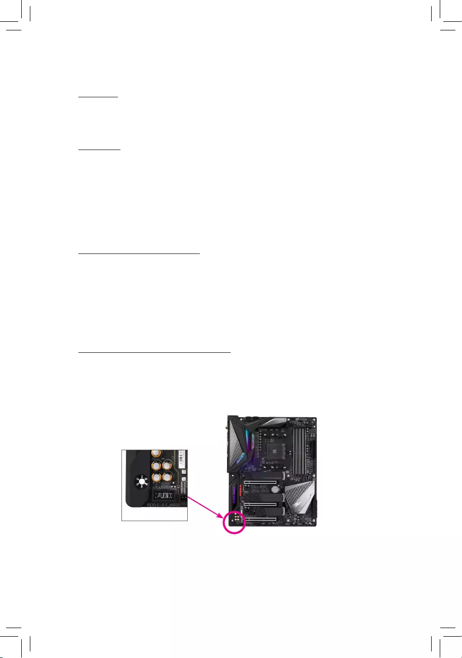
Identifying Your Motherboard Revision
The revision number on your motherboard looks like this: «REV: X.X.» For example, «REV:
1.0″ means the revision of the motherboard is 1.0. Check your motherboard revision before
updating motherboard BIOS, drivers, or when looking for technical information.
Example:

— 4 —
Table of Contents
Box Contents ……………………………………………………………………………………………………. 6
Optional Items …………………………………………………………………………………………………..6
X570 AORUS MASTER Motherboard Layout ………………………………………………………..7
Chapter 1 Hardware Installation ………………………………………………………………………….9
1-1 Installation Precautions ……………………………………………………………………….. 9
1-2 ProductSpecications ………………………….……………………………………………. 10
1-3 Installing the CPU and CPU Cooler……………………………………………………… 14
1-3-1 Installing the CPU ……………………………………………………………………………………..14
1-3-2 Installing the CPU Cooler …………………………………………………………………………..16
1-4 Installing the Memory ………………………………………………………………………… 17
1-4—1 DualChannelMemoryConguration …………………………………………………………..17
1-4-2 Installing a Memory ……………………………………………………………………………………18
1-5 Installing an Expansion Card ………………………………………………………………. 19
1-6
Setting up AMD CrossFire
™
/NVIDIA
®
SLI
™
Conguration …………………………. 20
1-7 Back Panel Connectors ……………………………………………………………………… 21
1-8 Onboard Buttons, Switches and LEDs …………………………………………………. 23
1-9 Internal Connectors …………………………………………………………………………… 25
Chapter 2 BIOS Setup ……………………………………………………………………………………..39
2-1 Startup Screen ………………………………………………………………………………….. 40
2-2 The Main Menu …………………………………………………………………………………. 41
2-3 Favorites (F11) ………………………………………………………………………………….. 43
2-4 Tweaker ……………………………………………………………………………………………. 44
2-5 Settings ……………………………………………………………………………………………. 48
2-6 System Info. ……………………………………………………………………………………… 54
2-7 Boot …………………………………………………………………………………………………. 55
2-8 Save & Exit ………………………………………………………………………………………. 58
Chapter3 ConguringaRAIDSet …………………………………………………………………….59
3—1 ConguringSATAControllers ……………………………………………………………… 59
3-2 Installing the SATA RAID/AHCI Driver and Operating System ………………… 64
Chapter 4 Drivers Installation ……………………………………………………………………………67
4—1 Drivers & Software …………………………………………………………………………….. 67
4-2 Application Software ………………………………………………………………………….. 68
4-3 Information ……………………………………………………………………………………….. 68

— 5 —
Chapter 5 Unique Features……………………………………………………………………………….69
5—1 BIOS Update Utilities …………………………………………………………………………. 69
5-1-1 Updating the BIOS with the Q—Flash Utility …………………………………………………. 69
5-1-2 Updating the BIOS with the @BIOS Utility ……………………………………………………72
5—1-3 Using Q-Flash Plus ……………………………………………………………………………………73
5-2 APP Center ………………………………………………………………………………………. 74
5-2-1 AutoGreen ………………………………………………………………………………………………..75
5-2-2 Cloud Station ……………………………………………………………………………………………76
5—2—3 EasyTune …………………………………………………………………………………………………. 81
5-2-4 Fast Boot ………………………………………………………………………………………………….82
5-2-5 Game Boost ……………………………………………………………………………………………. 83
5-2-6 RGB Fusion …………………………………………………………………………………………….. 84
5-2-7 Smart Keyboard ………………………………………………………………………………………. 86
5-2-8 Smart Backup …………………………………………………………………………………………..87
5-2—9 System Information Viewer ……………………………………………………………………….. 89
5-2-10 Smart Survey ………………………………………………………………………………………….. 90
5-2-11 USB Blocker ……………………………………………………………………………………………..91
5-2-12 USB TurboCharger ……………………………………………………………………………………92
Chapter 6 Appendix …………………………………………………………………………………………93
6—1 ConguringAudioInputandOutput …………………………………………………….. 93
6—1-1 Conguring2/4/5.1/7.1-ChannelAudio …………………………………………………………93
6—1-2 ConguringS/PDIFOut ……………………………………………………………………………. 95
6-1-3 Stereo Mix ………………………………………………………………………………….. 96
6—1-4 Using the Voice Recorder …………………………………………………………………………..97
6-2 Troubleshooting ………………………………………………………………………………… 98
6-2-1 Frequently Asked Questions …………………………………………………………………….. 98
6-2-2 Troubleshooting Procedure ………………………………………………………………………. 99
6-3 Debug LED Codes …………………………………………………………………………… 101
Regulatory Statements ………………………………………………………………………………. 105
Contact Us …………………………………………………………………………………………………111

— 6 —
Box Contents
5X570 AORUS MASTER motherboard
5Motherboard driver disk
5User’s Manual
5Quick Installation Guide
5Four SATA cables
5One Wi-Fi antenna
5One G Connector
5One addressable LED strip adapter cable
5One RGB LED strip extension cable
5One noise detection cable
5Two Velcro cable ties
5Two thermistors cables
5M.2 screw(s)/M.2 standoff(s)
Optional Items
2-port USB 2.0 bracket (Part No. 12CR1-1UB030-6*R)
eSATA bracket (Part No. 12CF1-3SATPW-4*R)
3.5″ Front Panel with 2 USB 3.1 Gen 1 ports (Part No. 12CR1-FPX582-2*R)
The box contents above are for reference only and the actual items shall depend on the product package you obtain.
The box contents are subject to change without notice.
— 7 —
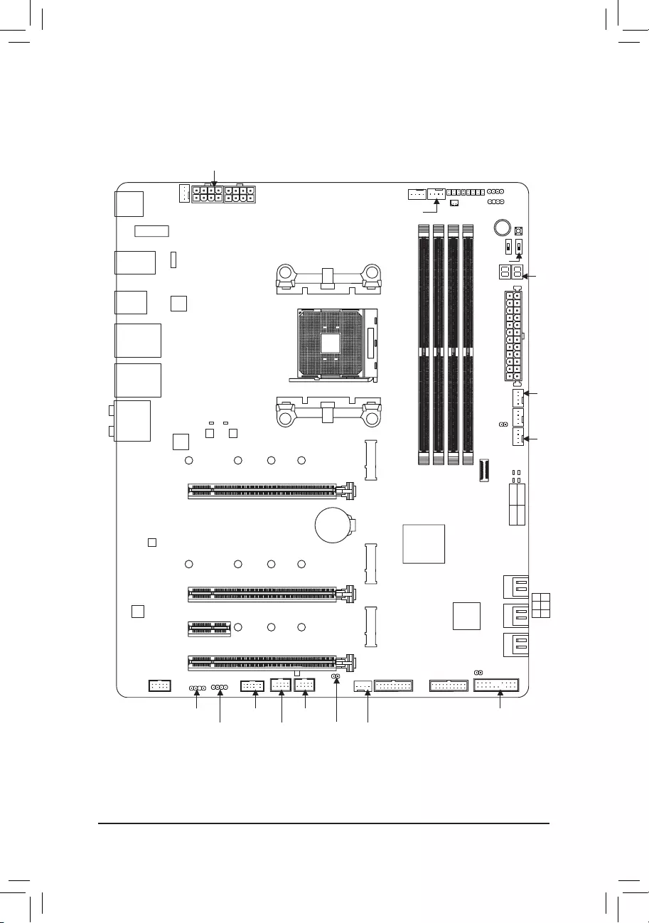
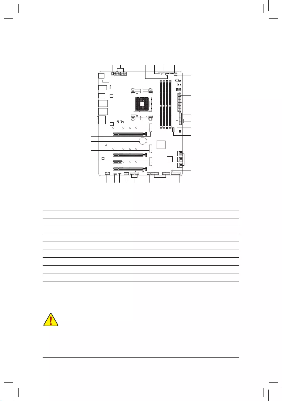
X570 AORUS MASTER Motherboard Layout
(Note) For debug code information, please refer to Chapter 6.
R_USB
R_USB30
TYPEC
USB31_LAN2
USB31_LAN1
Socket AM4 ATX
AUDIO
ATX_12V
AMD X570
M_BIOS
B_BIOS
PCIEX8
PCIEX4
PCIEX16
PCIEX1
F_USB30_1
F_USB31C
SYS_FAN5_PUMP
M2A_SOCKET
CODEC
X570 AORUS MASTER
F_PANEL
SYS_FAN1 CPU_FAN
LED_C2
CPU_OPT
iTE®
Super I/O
426080110
SATA3 420
531
BAT
Intel® GbE
LAN
EC_TEMP1
EC_TEMP2
CLR_CMOS
SYS_FAN6_PUMP
DB_PORT (Note)
F_USB1
F_USB2
TPM
LED_C1
D_LED1
F_AUDIO
ESS SABRE9118
USB 2.0 Hub
M2B_SOCKET
426080110
M2C_SOCKET
426080
D_LED2
VGA CPU
BOOT DRAM
ATX_12V1
REAR_BUTTON
M2_WIFI
MBIOS_LED
BBIOS_LED
NOISE SENSOR
PW_SW
RST_SW
BIOS_SW
SB
SYS_FAN2
SYS_FAN4
F_USB30_2
Realtek® GbE
LAN
USB 2.0 Hub
DDR4_A1
DDR4_A2
DDR4_B1
DDR4_B2

— 8 —

— 9 —
Chapter 1 Hardware Installation
1-1 Installation Precautions
The motherboard contains numerous delicate electronic circuits and components which can become
damaged as a result of electrostatic discharge (ESD). Prior to installation, carefully read the user’s
manual and follow these procedures:
•Prior to installation, make sure the chassis is suitable for the motherboard.
•Prior to installation, do not remove or break motherboard S/N (Serial Number) sticker or
warranty sticker provided by your dealer. These stickers are required for warranty validation.
•Always remove the AC power by unplugging the power cord from the power outlet before
installing or removing the motherboard or other hardware components.
•When connecting hardware components to the internal connectors on the motherboard, make
sure they are connected tightly and securely.
•When handling the motherboard, avoid touching any metal leads or connectors.
•It is best to wear an electrostatic discharge (ESD) wrist strap when handling electronic com-
ponents such as a motherboard, CPU or memory. If you do not have an ESD wrist strap, keep
your hands dry and rst touch a metal object to eliminate static electricity.
•Prior to installing the motherboard, please have it on top of an antistatic pad or within an
electrostatic shielding container.
•Before connecting or unplugging the power supply cable from the motherboard, make sure
the power supply has been turned off.
•Before turning on the power, make sure the power supply voltage has been set according to
the local voltage standard.
•Before using the product, please verify that all cables and power connectors of your hardware
components are connected.
•To prevent damage to the motherboard, do not allow screws to come in contact with the
motherboard circuit or its components.
•Make sure there are no leftover screws or metal components placed on the motherboard or
within the computer casing.
•Do not place the computer system on an uneven surface.
•Do not place the computer system in a high-temperature or wet environment.
•Turning on the computer power during the installation process can lead to damage to system
components as well as physical harm to the user.
•If you are uncertain about any installation steps or have a problem related to the use of the
product, please consult a certied computer technician.
•If you use an adapter, extension power cable, or power strip, ensure to consult with its instal-
lation and/or grounding instructions.
— 10 —
1-2 ProductSpecications
CPU AMD Socket AM4, support for:
3rd Generation AMD Ryzen™ processors/
2nd Generation AMD Ryzen™ processors/
2nd Generation AMD Ryzen™ with Radeon™ Vega Graphics processors/
AMD Ryzen™ with Radeon™ Vega Graphics processors
(Go to GIGABYTE’s website for the latest CPU support list.)
Chipset AMD X570
Memory
3rd Generation AMD Ryzen
™
processors
:
— Support for DDR4 3200/2933/2667/2400/2133 MHz memory modules
2nd Generation AMD Ryzen
™
processors/2nd Generation AMD Ryzen
™
with Radeon
™
Vega Graphics processors/AMD Ryzen
™
with Radeon
™
Vega Graphics processors
:
— Support for DDR4 2933/2667/2400/2133 MHz memory modules
4 x DDR4 DIMM sockets supporting up to 128 GB (32 GB single DIMM capacity)
of system memory
Dual channel memory architecture
Support for ECC Un-buffered DIMM 1Rx8/2Rx8 memory modules
Support for non-ECC Un-buffered DIMM 1Rx8/2Rx8/1Rx16 memory modules
Support for Extreme Memory Prole (XMP) memory modules
(Go to GIGABYTE’s website for the latest supported memory speeds and memory
modules.)
Audio Realtek® ALC1220-VB codec
* The front panel line out jack supports DSD audio.
ESS SABRE9118 DAC chip
High Denition Audio
2/4/5.1/7.1-channel
Support for S/PDIF Out
LAN 1 x Intel® GbE LAN chip (10/100/1000 Mbit) (LAN1)
1 x Realtek® GbE LAN chip (10/100/1000/2500 Mbit) (LAN2)
Wireless
Communication
Module
Wi-Fi 802.11a/b/g/n/ac/ax, supporting 2.4/5 GHz Dual-Band
BLUETOOTH 5.0
Support for 11ax 160MHz wireless standard and up to 2.4 Gbps data rate
* Actual data rate may vary depending on environment and equipment.
Expansion Slots Integrated in the CPU (PCIEX16/PCIEX8):
3rd Generation AMD Ryzen
™
processors
:
—
1 x PCI Express x16 slot, supporting PCIe 4.0 and running at x16 (PCIEX16)
— 1 x PCI Express x16 slot, supporting PCIe 4.0 and running at x8 (PCIEX8)
2nd Generation AMD Ryzen
™
processors
:
—
1 x PCI Express x16 slot, supporting PCIe 3.0 and running at x16 (PCIEX16)
— 1 x PCI Express x16 slot, supporting PCIe 3.0 and running at x8 (PCIEX8)
* For optimum performance, if only one PCI Express graphics card is to be installed,
be sure to install it in the PCIEX16 slot.
* The PCIEX8 slot shares bandwidth with the PCIEX16 slot. When using the 3rd
Generation AMD Ryzen™ processors/2nd Generation AMD Ryzen™ processors,
the PCIEX16 slot operates at up to x8 mode.
2nd Generation AMD Ryzen
™
with Radeon
™
Vega Graphics processors/AMD Ryzen
™
with Radeon
™
Vega Graphics processors
:
—
1 x PCI Express x16 slot, supporting PCIe 3.0 and running at x8 (PCIEX16)
— 11 —
Expansion Slots Integrated in the Chipset (PCIEX4/PCIEX1):
— 1 x PCI Express x16 slot, supporting PCIe 4.0 (Note 1)/3.0 and running at x4
(PCIEX4)
— 1 x PCI Express x1 slot, supporting PCIe 4.0 (Note 1)/3.0
Multi-Graphics
Technology (Note 2)
Support for NVIDIA® Quad-GPU SLI™ and 2-Way NVIDIA® SLI™ technologies
Support for AMD Quad-GPU CrossFire™ and 2-Way AMD CrossFire™ technologies
Storage Interface Integrated in the CPU (M2A_SOCKET):
3rd Generation AMD Ryzen
™
processors
:
— 1 x M.2 connector (Socket 3, M key, type 2242/2260/2280/22110 SATA and
PCIe 4.0 x4/x2 SSD support)
2nd Generation AMD Ryzen
™
processors/2nd Generation AMD Ryzen
™
with Radeon
™
Vega Graphics processors/AMD Ryzen
™
with Radeon
™
Vega Graphics processors
:
— 1 x M.2 connector (Socket 3, M key, type 2242/2260/2280/22110 SATA and
PCIe 3.0 x4/x2 SSD support)
Integrated in the Chipset (M2B_SOCKET/M2C_SOCKET):
— 1 x M.2 connector (Socket 3, M key, type 2242/2260/2280/22110 SATA and
PCIe 4.0 (Note 1)/3.0 x4/x2 SSD support) (M2B_SOCKET)
— 1 x M.2 connector (Socket 3, M key, type 2242/2260/2280 SATA and PCIe
4.0 (Note 1)/3.0 x4/x2 SSD support) (M2C_SOCKET)
— 6 x SATA 6Gb/s connectors
— Support for RAID 0, RAID 1, and RAID 10
* Refer to «1-9 Internal Connectors,» for the installation notices for the M.2 and SATA
connectors.
USB Integrated in the CPU:
— 2 x USB 3.1 Gen 2 (Note 1)/Gen 1 Type-A ports (red) on the back panel
— 2 x USB 3.1 Gen 1 ports on the back panel
Integrated in the Chipset:
— 1 x USB Type-C™ port with USB 3.1 Gen 2 support, available through the
internal USB header
— 1 x USB Type-C™ port on the back panel, with USB 3.1 Gen 2 support
— 1 x USB 3.1 Gen 2 Type-A port (red) on the back panel
— 4 x USB 3.1 Gen 1 ports available through the internal USB headers
Chipset+USB 2.0 Hub:
— 8 x USB 2.0/1.1 ports (4 ports on the back panel, 4 ports available through
the internal USB headers)
(Note 1) For
3rd Generation AMD Ryzen
™
processors
only.
(Note 2) For
3rd Generation AMD Ryzen
™
processors
/
2nd Generation AMD Ryzen
™
processors
only.
— 12 —
Internal
Connectors
1 x 24-pin ATX main power connector
2 x 8-pin ATX 12V power connectors
1 x CPU fan header
1 x water cooling CPU fan header
3 x system fan headers
2 x system fan/water cooling pump headers
2 x addressable LED strip headers
2 x RGB LED strip headers
3 x M.2 Socket 3 connectors
6 x SATA 6Gb/s connectors
1 x front panel header
1 x front panel audio header
1 x USB Type-C™ port, with USB 3.1 Gen 2 support
2 x USB 3.1 Gen 1 headers
2 x USB 2.0/1.1 headers
1 x noise detection header
1 x Trusted Platform Module (TPM) header (2×6 pin, for the GC-TPM2.0_S
module only)
2 x temperature sensor headers
1 x power button
1 x reset button
2 x BIOS switches
1 x Clear CMOS jumper
Voltage Measurement Points
Back Panel
Connectors
1 x Q-Flash Plus button
1 x Clear CMOS button
2 x SMA antenna connectors (2T2R)
1 x USB Type-C™ port, with USB 3.1 Gen 2 support
2 x USB 3.1 Gen 2 (Note 1)/Gen 1 Type-A ports (red)
1 x USB 3.1 Gen 2 Type-A port (red)
2 x USB 3.1 Gen 1 ports
4 x USB 2.0/1.1 ports
2 x RJ-45 ports
1 x optical S/PDIF Out connector
5 x audio jacks
I/O Controller
iTE® I/O Controller Chip
Hardware
Monitor
Voltage detection
Temperature detection
Fan speed detection
Water cooling ow rate detection
Overheating warning
Fan fail warning
Fan speed control
* Whether the fan (pump) speed control function is supported will depend on the fan
(pump) you install.
Noise detection
(Note 1) For
3rd Generation AMD Ryzen
™
processors
only.
— 13 —
BIOS 2 x 128 Mbit ash
Use of licensed AMI UEFI BIOS
Support for DualBIOS™
PnP 1.0a, DMI 2.7, WfM 2.0, SM BIOS 2.7, ACPI 5.0
Unique Features Support for APP Center
* Available applications in APP Center may vary by motherboard model. Supported
functions of each application may also vary depending on motherboard specications.
— @BIOS
— AutoGreen
— Cloud Station
— EasyTune
— Fast Boot
— Game Boost
— RGB Fusion
— Smart Backup
— Smart Keyboard
— Smart Survey
— System Information Viewer
— USB Blocker
— USB TurboCharger
Support for Q-Flash Plus
Support for Q-Flash
Support for Xpress Install
Bundled
Software
Norton® Internet Security (OEM version)
cFosSpeed
XSplit Gamecaster + Broadcaster (12 months license)
Operating
System Support for Windows 10 64-bit
Form Factor
ATX Form Factor; 30.5cm x 24.4cm
* GIGABYTE reserves the right to make any changes to the product specications and product-related information without
prior notice.
Please visit GIGABYTE’s website for
support lists of CPU, memory mod-
ules, SSDs, and M.2 devices.
Please visit the Support\Utility List
page on GIGABYTE’s website to
download the latest version of apps.
— 14 —
1-3 Installing the CPU and CPU Cooler
Read the following guidelines before you begin to install the CPU:
•Make sure that the motherboard supports the CPU.
(Go to GIGABYTE’s website for the latest CPU support list.)
•Always turn off the computer and unplug the power cord from the power outlet before installing the
CPU to prevent hardware damage.
•Locate the pin one of the CPU. The CPU cannot be inserted if oriented incorrectly.
•Apply an even and thin layer of thermal grease on the surface of the CPU.
•Do not turn on the computer if the CPU cooler is not installed, otherwise overheating and damage
of the CPU may occur.
•Set the CPU host frequency in accordance with the CPU specications. It is not recommended
that the system bus frequency be set beyond hardware specications since it does not meet the
standard requirements for the peripherals. If you wish to set the frequency beyond the standard
specications, please do so according to your hardware specications including the CPU, graphics
card, memory, hard drive, etc.
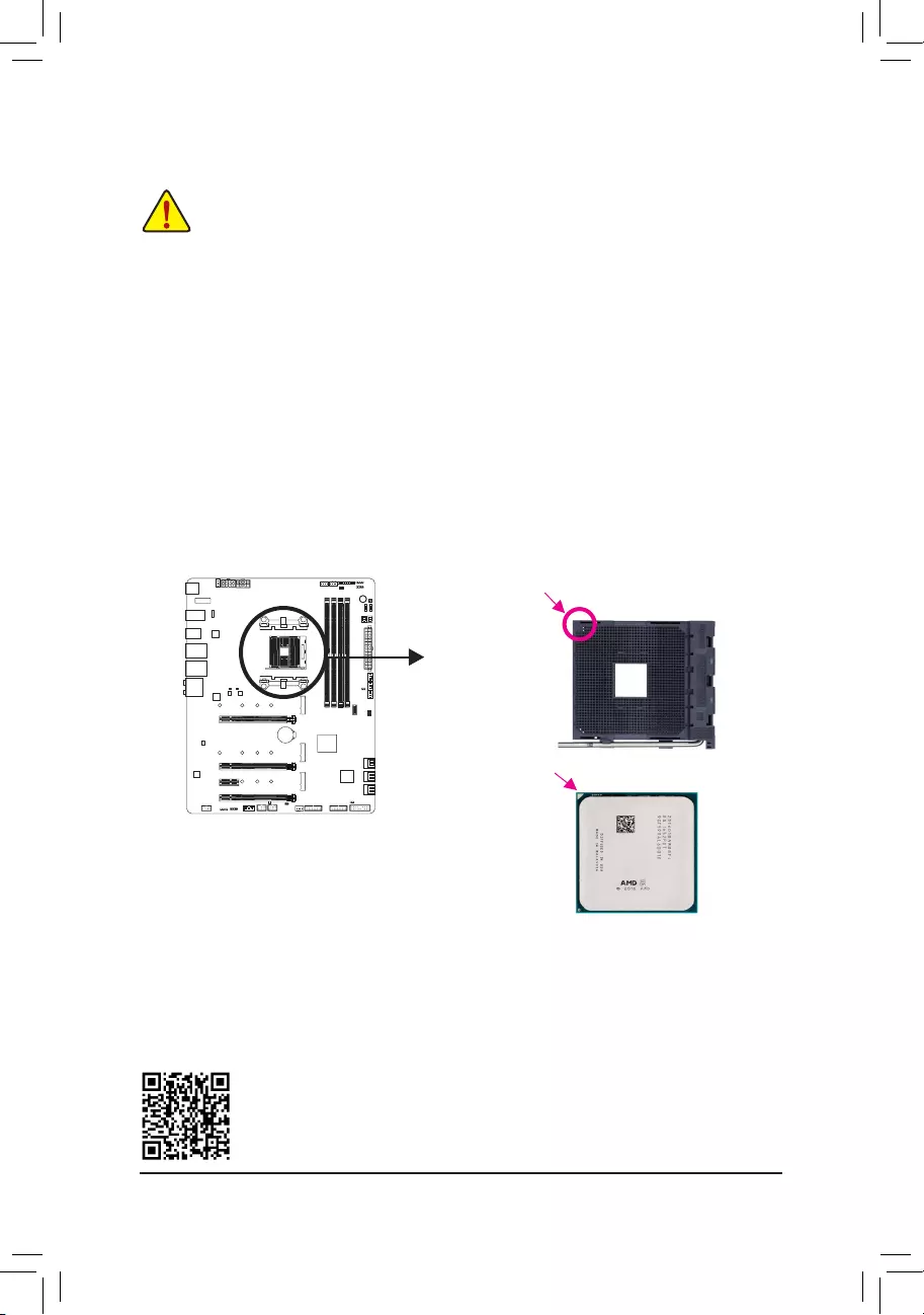
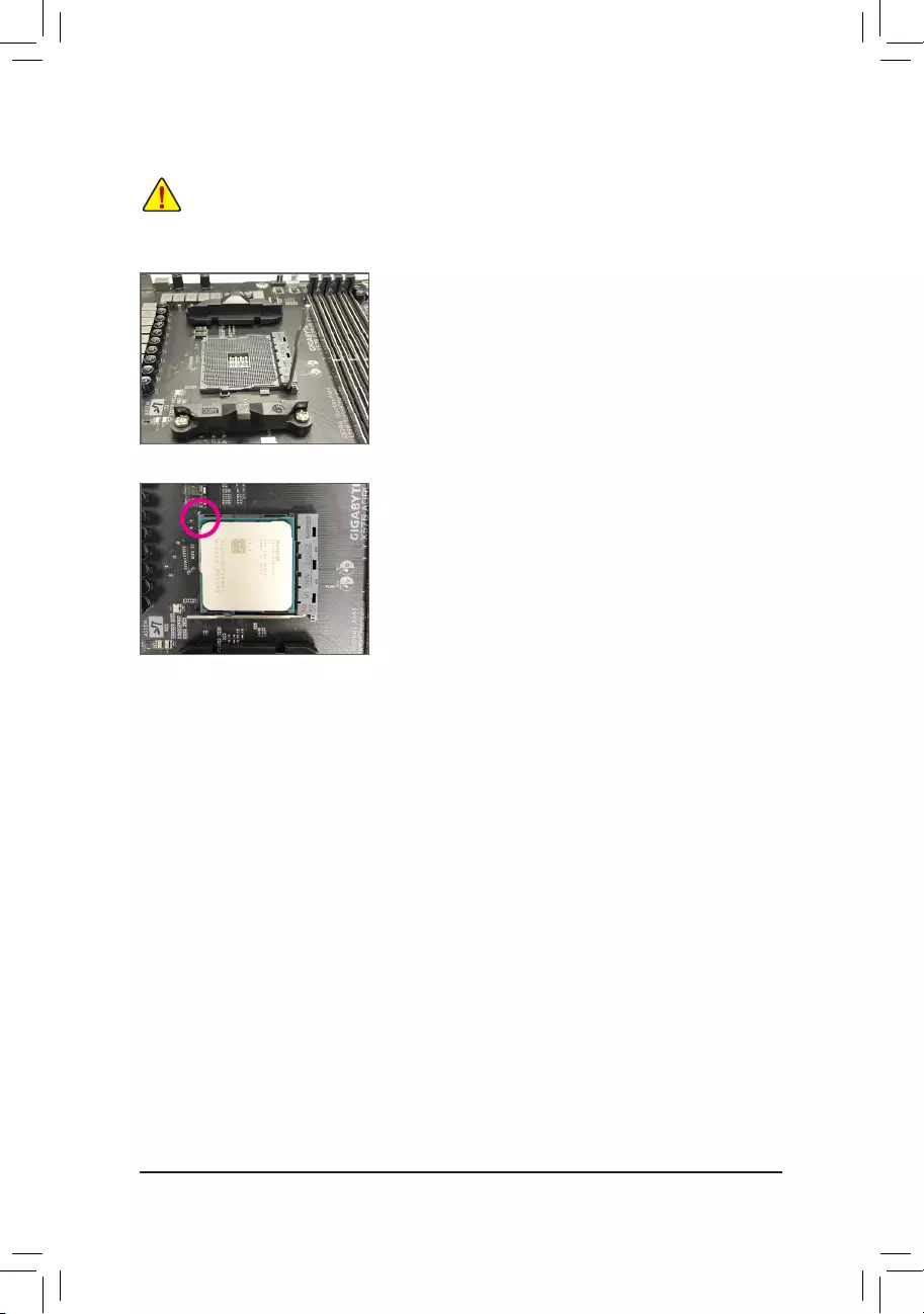
1-3-1 Installing the CPU
A. Locate the pin one (denoted by a small triangle) of the CPU socket and the CPU.
Please visit GIGABYTE’s website for details on hardware installation.
AM4 Socket
A Small Triangle Mark—
ing Denotes Pin One
of the Socket
AM4 CPU
A Small Triangle Mark-
ing Denotes CPU Pin
One
— 15 —
B. Follow the steps below to correctly install the CPU into the motherboard CPU socket.
•Before installing the CPU, make sure to turn off the computer and unplug the power cord from the
power outlet to prevent damage to the CPU.
•Do not force the CPU into the CPU socket. The CPU cannot t in if oriented incorrectly. Adjust the
CPU orientation if this occurs.
Step 1:
Completely lift up the CPU socket locking lever.
Step 2:
Align the CPU pin one (small triangle marking) with the triangle mark
on the CPU socket and gently insert the CPU into the socket. Make
sure that the CPU pins t perfectly into their holes.
Once the CPU is positioned into its socket, place one nger down on
the middle of the CPU, lowering the locking lever and latching it into
the fully locked position.
— 16 —
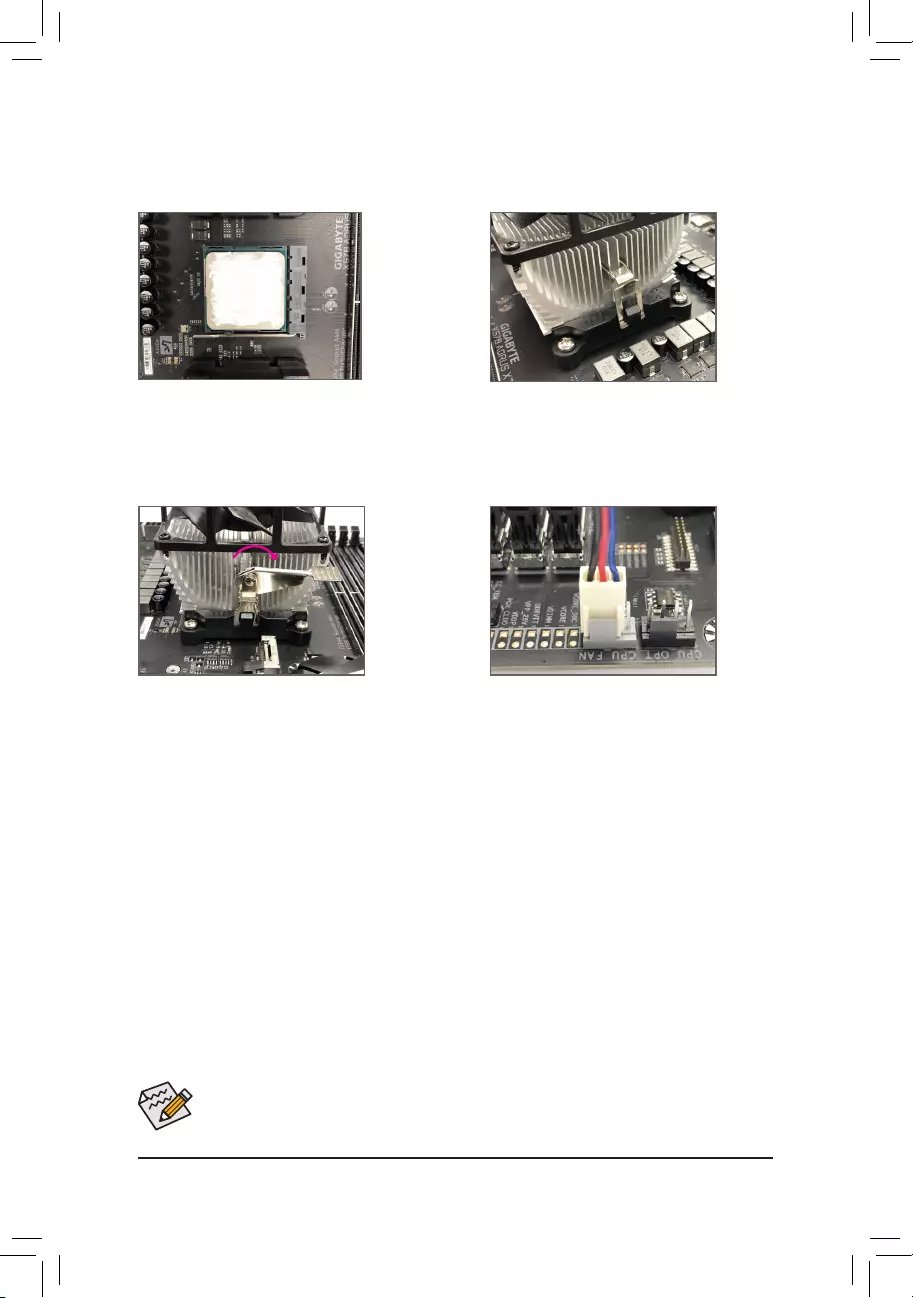
1-3-2 Installing the CPU Cooler
Follow the steps below to correctly install the CPU cooler on the motherboard.
Use extreme care when removing the CPU cooler because the thermal grease/tape between the CPU
cooler and CPU may adhere to the CPU. Inadequately removing the CPU cooler may damage the CPU.
Step 1:
Apply an even and thin layer of thermal grease on
the surface of the installed CPU.
Step 2:
Hook the CPU cooler clip to the mounting lug on
one side of the retention frame. On the other side,
push straight down on the CPU cooler clip to hook
it to the mounting lug on the retention frame.
Step 3:
Turn the cam handle from the left side to the
right side (as the picture above shows) to lock
into place. (Refer to your CPU cooler installation
manual for instructions on installing the cooler.)
Step 4:
Finally, attach the power connector of the CPU
cooler to the CPU fan header (CPU_FAN) on the
motherboard.
— 17 —
1-4 Installing the Memory
Read the following guidelines before you begin to install the memory:
•Make sure that the motherboard supports the memory. It is recommended that memory of the same
capacity, brand, speed, and chips be used.
(Go to GIGABYTE’s website for the latest supported memory speeds and memory modules.)
•Always turn off the computer and unplug the power cord from the power outlet before installing the
memory to prevent hardware damage.
•Memory modules have a foolproof design. A memory module can be installed in only one direction.
If you are unable to insert the memory, switch the direction.
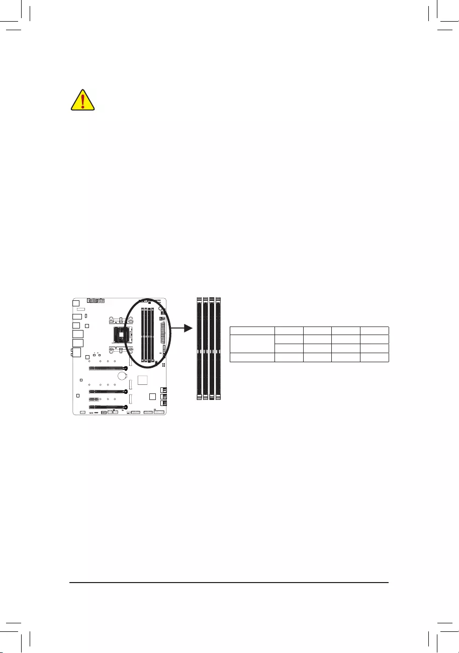
1-4-1 DualChannelMemoryConguration
This motherboard provides four memory sockets and supports Dual Channel Technology. After the memory
is installed, the BIOS will automatically detect the specications and capacity of the memory. Enabling Dual
Channel memory mode will double the original memory bandwidth.
The four DDR4 memory sockets are divided into two channels and each channel has two memory sockets as
following:
Channel A: DDR4_A1, DDR4_A2
Channel B: DDR4_B1, DDR4_B2
Due to CPU limitations, read the following guidelines before installing the memory in Dual Channel mode.
1. Dual Channel mode cannot be enabled if only one memory module is installed.
2. When enabling Dual Channel mode with two or four memory modules, it is recommended that memory
of the same capacity, brand, speed, and chips be used. For optimum performance, when enabling
Dual Channel mode with two memory modules, we recommend that you install them in the DDR4_A2
and DDR4_B2 sockets.
DDR4_B2
DDR4_A1
DDR4_A2
DDR4_B1
Dual Channel Memory Congurations Table
DDR4_A1 DDR4_A2 DDR4_B1 DDR4_B2
2 Modules — — DS/SS — — DS/SS
DS/SS — — DS/SS — —
4 Modules DS/SS DS/SS DS/SS DS/SS
(SS=Single-Sided, DS=Double-Sided, «- -«=No Memory)
— 18 —
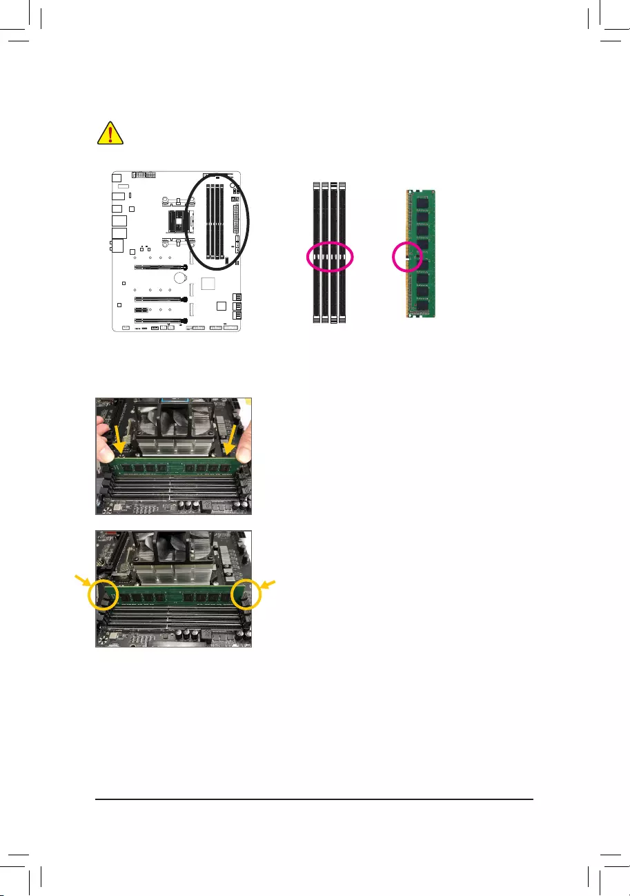
1-4-2 Installing a Memory
Before installing a memory module, make sure to turn off the computer and unplug the power cord
from the power outlet to prevent damage to the memory module. DDR4 and DDR3 DIMMs are not
compatible to each other or DDR2 DIMMs. Be sure to install DDR4 DIMMs on this motherboard.
Notch
DDR4 DIMM
A DDR4 memory module has a notch, so it can only t in one direction. Follow the steps below to correctly install
your memory modules in the memory sockets.
Step 1:
Note the orientation of the memory module. Spread the retaining clips
at both ends of the memory socket. Place the memory module on the
socket. As indicated in the picture on the left, place your ngers on
the top edge of the memory, push down on the memory and insert it
vertically into the memory socket.
Step 2:
The clips at both ends of the socket will snap into place when the
memory module is securely inserted.
— 19 —
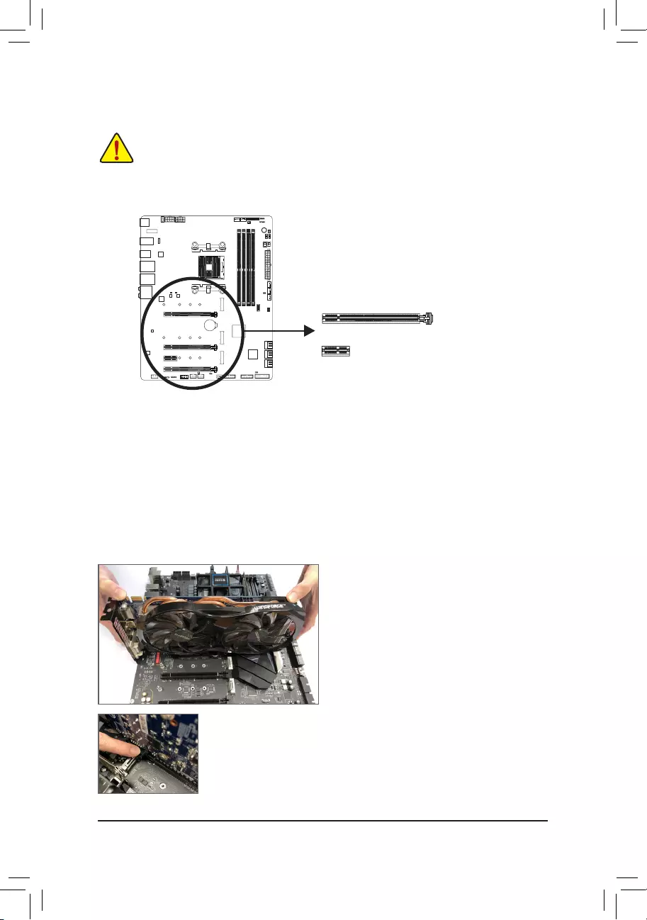
1-5 Installing an Expansion Card
Read the following guidelines before you begin to install an expansion card:
•Make sure the motherboard supports the expansion card. Carefully read the manual that came
with your expansion card.
•Always turn off the computer and unplug the power cord from the power outlet before installing an
expansion card to prevent hardware damage.
Follow the steps below to correctly install your expansion card in the expansion slot.
1. Locate an expansion slot that supports your card. Remove the metal slot cover from the chassis back panel.
2. Align the card with the slot, and press down on the card until it is fully seated in the slot.
3. Make sure the metal contacts on the card are completely inserted into the slot.
4. Secure the card’s metal bracket to the chassis back panel with a screw.
5. After installing all expansion cards, replace the chassis cover(s).
6. Turn on your computer. If necessary, go to BIOS Setup to make any required BIOS changes for your expan—
sion card(s).
7. Install the driver provided with the expansion card in your operating system.
Example: Installing and Removing a PCI Express Graphics Card:
PCI Express x1 Slot
PCI Express x16 Slot
•Installing a Graphics Card:
Gently push down on the top edge of the card until
it is fully inserted into the PCI Express slot. Make
sure the card is securely seated in the slot and
does not rock.
•Removing the Card:
Gently push back on the lever on the slot and then lift the card straight out from
the slot.
— 20 —
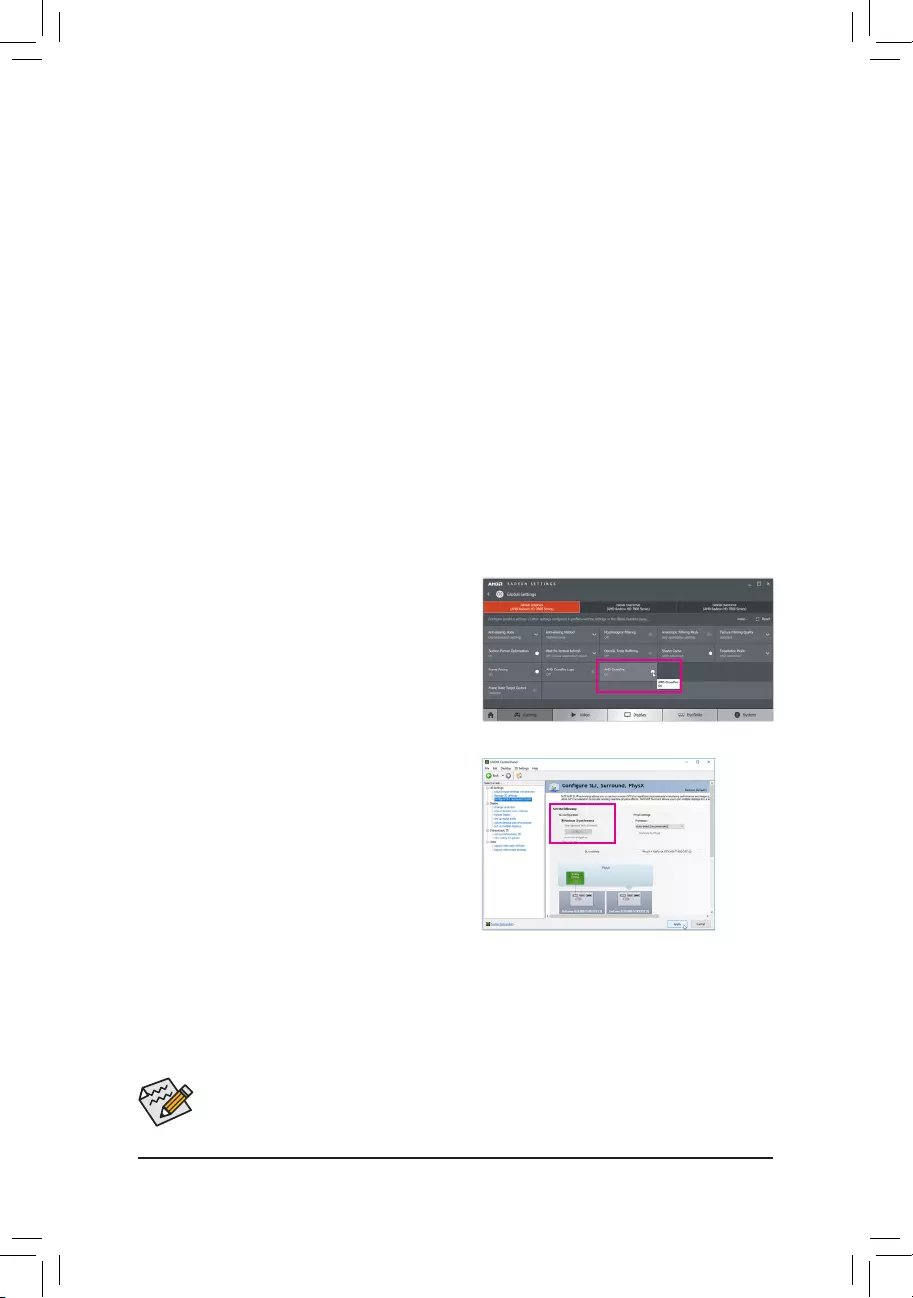
1-6
Setting up AMD CrossFire™/NVIDIA® SLI™Conguration(Note 1)
Procedure and driver screen for enabling CrossFire/SLI technology may differ by graphics cards and
driver version. Refer to the manual that came with your graphics cards for more information about
enabling CrossFire/SLI technology.
(Note 1) For
3rd Generation AMD Ryzen
™
processors
/
2nd Generation AMD Ryzen
™
processors
only.
(Note 2) The bridge connector(s) may be needed or not depending on your graphics cards.
C-2. To Enable SLI Function
After installing the graphics card driver in the operating
system, go to the NVIDIA Control Panel. Browse to the
CongureSLI, Surround,PhysX screen and ensure
Maximize 3D performance is enabled.
A. System Requirements
—Windows 10 64-bit operating system
—A CrossFire/SLI-supported motherboard with two or more PCI Express x16 slots and correct driver
—CrossFire/SLI-ready graphics cards of identical brand and chip and correct driver
—CrossFire (Note 2)/SLI bridge connectors
—A power supply with sufcient power is recommended (Refer to the manual of your graphics cards for the
power requirement)
B. Connecting the Graphics Cards
Step 1:
Observe the steps in «1-5 Installing an Expansion Card» and install CrossFire/SLI graphics cards on the PCI
Express x16 slots. (To set up a 2-Way conguration, we recommend installing the graphics cards on the
PCIEX16 and PCIEX8 slots.)
Step 2:
Insert the CrossFire (Note 2)/SLI bridge connectors in the CrossFire/SLI gold edge connectors on top of the cards.
Step 3:
Plug the display cable into the graphics card on the PCIEX16 slot.
C.ConguringtheGraphicsCardDriver
C-1. To Enable CrossFire Function
After installing the graphics card driver in the operating
system, go to the AMD RADEON SETTINGS screen.
Browse to Gaming\Global Settings and ensure AMD
CrossFire is set to On.
— 21 —
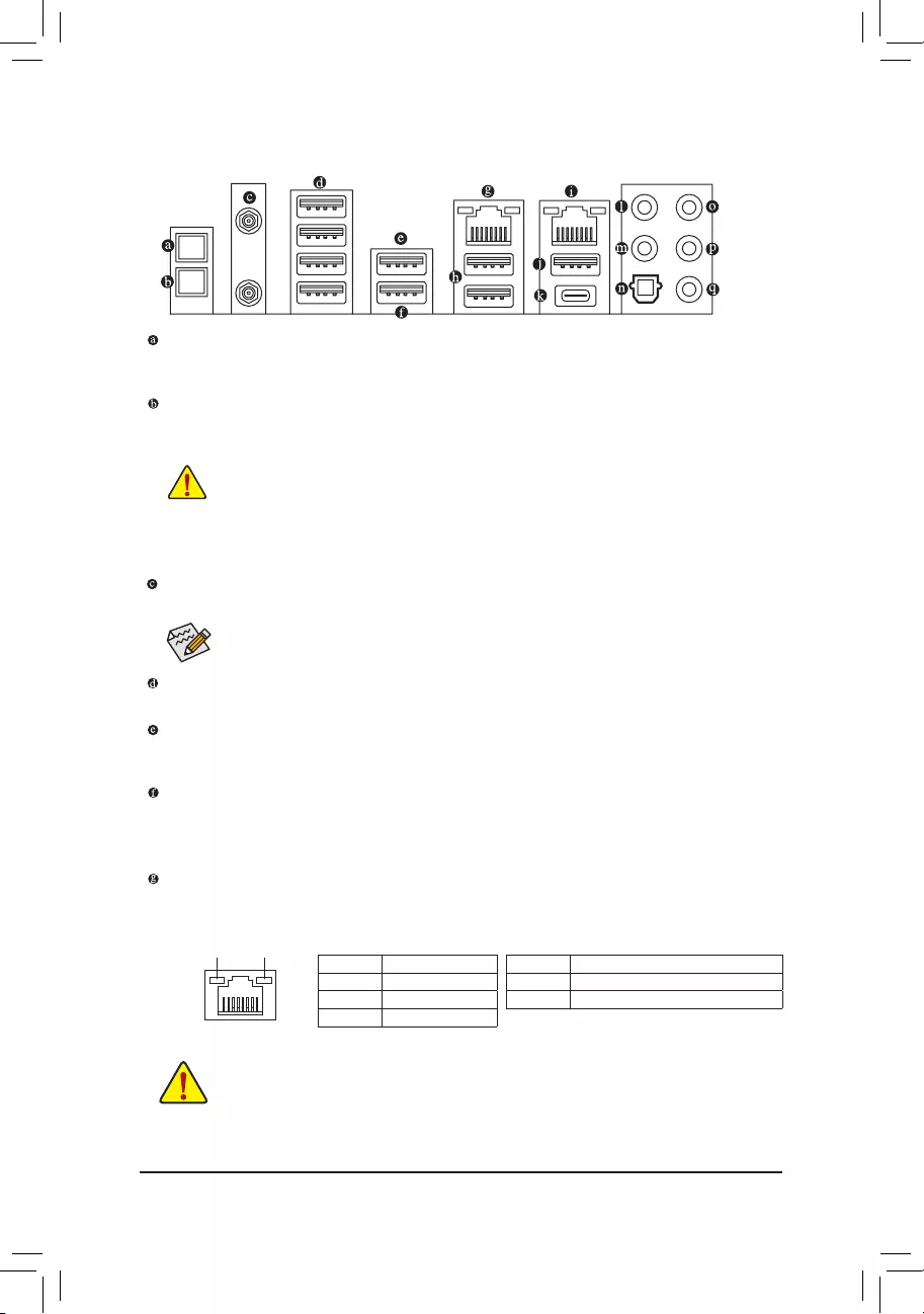
1-7 Back Panel Connectors
Q-Flash Plus Button (Note)
This button allows you to update the BIOS when the power connector is connected but the system is not
powered on.
Clear CMOS Button
Use this button to clear the CMOS values (e.g. BIOS conguration) and reset the CMOS values to factory
defaults when needed.
•When removing the cable connected to a back panel connector, rst remove the cable from your
device and then remove it from the motherboard.
•When removing the cable, pull it straight out from the connector. Do not rock it side to side to
prevent an electrical short inside the cable connector.
•Always turn off your computer and unplug the power cord from the power outlet before using
the clear CMOS button.
•Do not use the clear CMOS button when the system is on, or the system may shutdown and
data loss or damage may occur.
•After system restart, go to BIOS Setup to load factory defaults (select Load Optimized Defaults) or
manually congure the BIOS settings (refer to Chapter 2, «BIOS Setup,» for BIOS congurations).
SMA Antenna Connectors (2T2R)
Use this connector to connect an antenna.
Tighten the antenna cables to the antenna connectors and then move the antenna to a place
where the signal is good.
USB 2.0/1.1 Port
The USB port supports the USB 2.0/1.1 specication. Use this port for USB devices.
USB 3.1 Gen 1 Port
The USB 3.1 Gen 1 port supports the USB 3.1 Gen 1 specication and is compatible to the USB 2.0
specication. Use this port for USB devices.
USB 3.1 Gen 1 Port (White)
The USB 3.1 Gen 1 port supports the USB 3.1 Gen 1 specication and is compatible to the USB 2.0
specication. Use this port for USB devices. Before using Q-Flash Plus (Note), make sure to insert the USB
ash drive into this port rst.
RJ-45 LAN Port (LAN2)
The Gigabit Ethernet LAN port provides Internet connection at up to 2.5 Gbps data rate. The following
describes the states of the LAN port LEDs.
(Note) To enable Q-Flash Plus function, refer to Chapter 5, «Unique Features,» for more information.
Activity LED
Connection/
Speed LED
LAN Port
Activity LED:Connection/Speed LED:
State Description
Orange 2.5 Gbps data rate
Green 1 Gbps data rate
Off 100/10 Mbps data rate
State Description
Blinking Data transmission or receiving is occurring
Off No data transmission or receiving is occurring
— 22 —
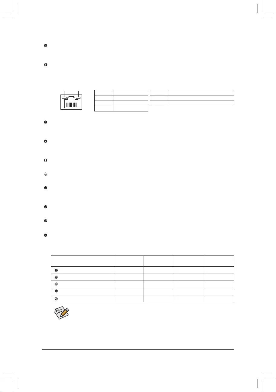
Activity LED
Connection/
Speed LED
LAN Port
Activity LED:Connection/Speed LED:
State Description
Orange 1 Gbps data rate
Green 100 Mbps data rate
Off 10 Mbps data rate
State Description
Blinking Data transmission or receiving is occurring
On No data transmission or receiving is occurring
USB 3.1 Gen 2 (Note)/Gen 1 Type-A Port (Red)
The USB 3.1 Gen 2 (Note)/Gen 1 Type-A port supports the USB 3.1 Gen 2 specication and is compatible
to the USB 3.1 Gen 1 and USB 2.0 specication. Use this port for USB devices.
RJ-45 LAN Port (LAN1)
The Gigabit Ethernet LAN port provides Internet connection at up to 1 Gbps data rate. The following
describes the states of the LAN port LEDs.
USB 3.1 Gen 2 Type-A Port (Red)
The USB 3.1 Gen 2 Type-A port supports the USB 3.1 Gen 2 specication and is compatible to the USB
3.1 Gen 1 and USB 2.0 specication. Use this port for USB devices.
USB Type-C™ Port
The reversible USB port supports the USB 3.1 Gen 2 specication and is compatible to the USB 3.1 Gen
1 and USB 2.0 specication. Use this port for USB devices.
Center/Subwoofer Speaker Out
Use this audio jack to connect center/subwoofer speakers.
Rear Speaker Out
Use this audio jack to connect rear speakers.
Optical S/PDIF Out Connector
This connector provides digital audio out to an external audio system that supports digital optical audio.
Before using this feature, ensure that your audio system provides an optical digital audio in connector.
Line In/Side Speaker Out
The line in jack. Use this audio jack for line in devices such as an optical drive, walkman, etc.
Line Out/Front Speaker Out
The line out jack.
Mic In/Side Speaker Out
The Mic in jack.
Audio Jack Congurations:
Jack Headphone/
2-channel 4-channel 5.1-channel 7.1-channel
Center/Subwoofer Speaker Out a a
Rear Speaker Out aaa
Line In/Side Speaker Out a
Line Out/Front Speaker Out aaaa
Mic In/Side Speaker Out a
If you want to install a Side Speaker, you need to retask either the Line in or Mic in jack to be
Side Speaker out through the audio driver.
(Note) For
3rd Generation AMD Ryzen
™
processors
only.
— 23 —
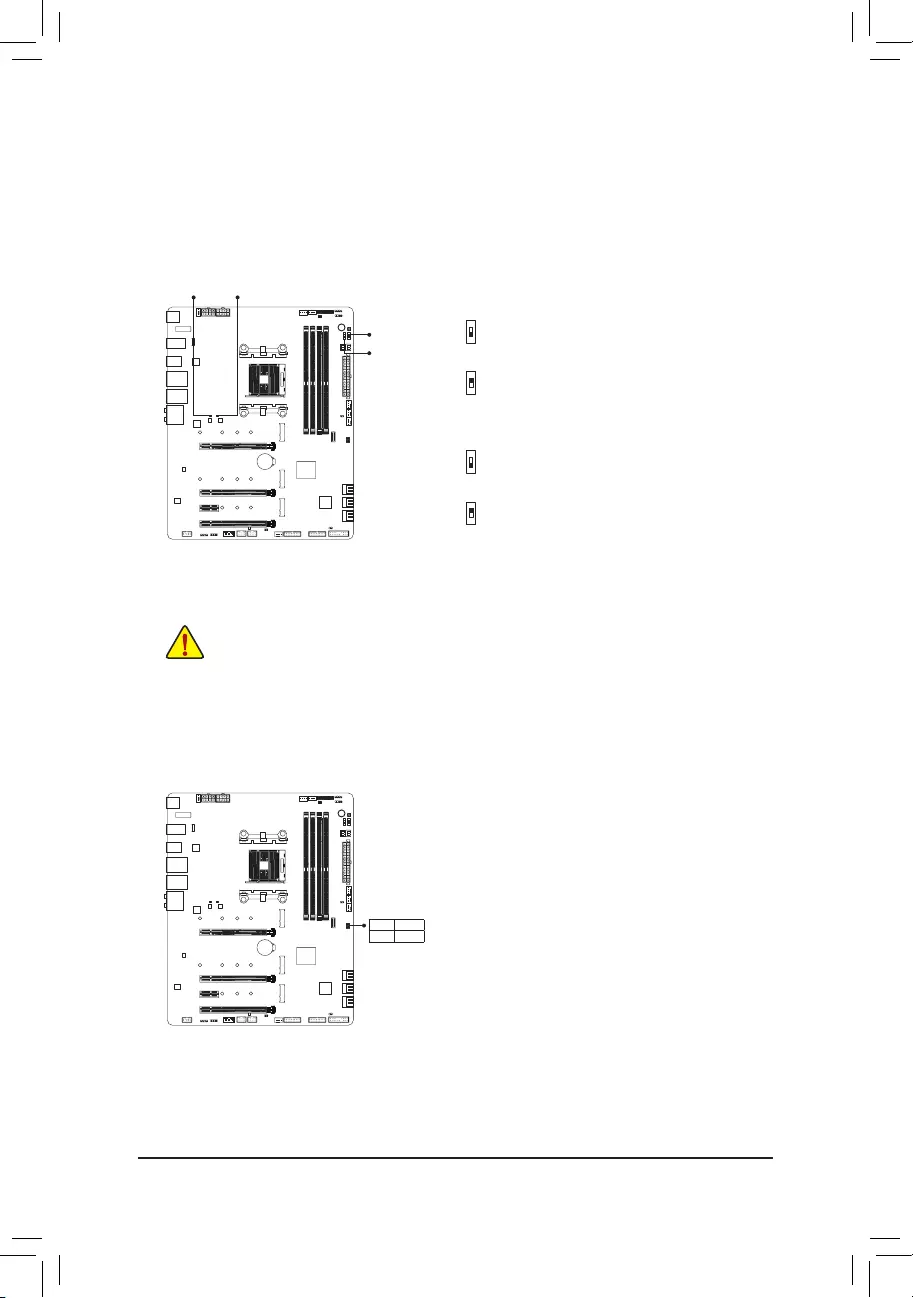
1-8 Onboard Buttons, Switches and LEDs
BIOS Switches and BIOS LED Indicators
The BIOS switch (BIOS_SW) allows users to easily select a different BIOS for boot up or overclocking, helping to
reduce BIOS failure during overclocking. The SB switch allows enabling or disabling of the Dual BIOS function.
The LED indicator (MBIOS_LED/BBIOS_LED) shows which BIOS is active.
2: Backup BIOS (Boot from the backup BIOS)
1: Main BIOS (Boot from the main BIOS)
BIOS_SW
2: Single BIOS
1: Dual BIOS
SB
F_USB30 F_U
B_
F_ F_
_
B
BS_
B
SB_
B
_S
S_
_
B
_U
_
B
S
123
123
123
123
1
1
1
1
BSS
S
_S
SSU
1 2 3 4 5
S3 BSSS
U
__ 3
F_USB3F
S _
S _
S _
SF
B_
B_
F
_0
S
S
_0F
_F
_
_
__B
U
S _S
_ SF_
B
USB0_B
B_ F_USB3
F_USB303
_
_3U
S_
1
2
F_USB30 F_U
B_
F_ F_
_
B
BS_
B
SB_
B
_S
S_
_
B
_U
_
B
S
123
123
123
123
1
1
1
1
BSS
S
_S
SSU
1 2 3 4 5
S3 BSSS
U
__ 3
F_USB3F
S _
S _
S _
SF
B_
B_
F
_0
S
S
_0F
_F
_
_
__B
U
S _S
_ SF_
B
USB0_B
B_ F_USB3
F_USB303
_
_3U
S_
1
2
MBIOS_LED (The main BIOS is active)
BBIOS_LED (The backup BIOS is active)
BIOS LED Indicators:
MBIOS_LEDBBIOS_LED
Status LEDs
The status LEDs show whether the CPU, memory, graphics card, and operating system are working properly
after system power-on. If the CPU/DRAM/VGA LED is on, that means the corresponding device is not working
normally; if the BOOT LED is on, that means you haven’t entered the operating system yet.
CPU: CPU status LED
DRAM: Memory status LED
VGA: Graphics card status LED
BOOT: Operating system status LED
Before setting the SB switch, be sure to turn off your computer and power supply.
BIOS_SW
SB
F_USB30 F_U
B_
F_ F_
_
B
BS_
B
SB_
B
_S
S_
_
B
_U
_
B
S
123
123
123
123
1
1
1
1
BSS
S
_S
SSU
1 2 3 4 5
S3 BSSS
U
__ 3
F_USB3F
S _
S _
S _
SF
B_
B_
F
_0
S
S
_0F
_F
_
_
__B
U
S _S
_ SF_
B
USB0_B
B_ F_USB3
F_USB303
_
_3U
S_
1
2
F_USB30 F_U
B_
F_ F_
_
B
BS_
B
SB_
B
_S
S_
_
B
_U
_
B
S
123
123
123
123
1
1
1
1
BSS
S
_S
SSU
1 2 3 4 5
S3 BSSS
U
__ 3
F_USB3F
S _
S _
S _
SF
B_
B_
F
_0
S
S
_0F
_F
_
_
__B
U
S _S
_ SF_
B
USB0_B
B_ F_USB3
F_USB303
_
_3U
S_
1
2
CPU DRAM
VGA BOOT
— 24 —
Quick Button
This motherboard has 2 quick buttons: power button and reset button. The power button and reset button allow
users to quickly turn on/off or reset the computer in an open-case environment when they want to change hardware
components or conduct hardware testing.
PW_SW: Power Button
RST_SW: Reset Button
RST_SW
PW_SW
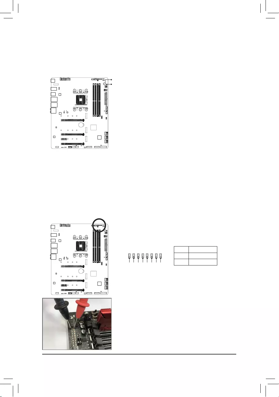
Voltage Measurement Points
Use a multimeter to measure the following motherboard voltages. You can employ following way to measure
component voltages.
Pin No. Denition
1 power
2 GND
F_USB30 F_U
B_
F_ F_
_
B
BS_
B
SB_
B
_S
S_
_
B
_U
_
B
S
123
123
123
123
1
1
1
1
BSS
S
_S
SSU
1 2 3 4 5
S3 BSSS U
__ 3
F_USB3F
S _
S _
S _
SF
B_
F
_0
S
S
_0F
_F
Pin 1 VCORE_SOC
F_USB30 F_U
B_
F_ F_
_
B
BS_
B
SB_
B
_S
S_
_
B
_U
_
B
S
123
123
123
123
1
1
1
1
BSS
S
_S
SSU
1 2 3 4 5
S3 BSSS U
__ 3
F_USB3F
S _
S _
S _
SF
B_
F
_0
S
S
_0F
_F
Pin 1 VCORE
F_USB30 F_U
B_
F_ F_
_
B
BS_
B
SB_
B
_S
S_
_
B
_U
_
B
S
123
123
123
123
1
1
1
1
BSS
S
_S
SSU
1 2 3 4 5
S3 BSSS U
__ 3
F_USB3F
S _
S _
S _
SF
B_
F
_0
S
S
_0F
_F
Pin 1 VDIMM
F_USB30 F_U
B_
F_ F_
_
B
BS_
B
SB_
B
_S
S_
_
B
_U
_
B
S
123
123
123
123
1
1
1
1
BSS
S
_S
SSU
1 2 3 4 5
S3 BSSS U
__ 3
F_USB3F
S _
S _
S _
SF
B_
F
_0
S
S
_0F
_F
Pin 1 DDRVTT
F_USB30 F_U
B_
F_ F_
_
B
BS_
B
SB_
B
_S
S_
_
B
_U
_
B
S
123
123
123
123
1
1
1
1
BSS
S
_S
SSU
1 2 3 4 5
S3 BSSS U
__ 3
F_USB3F
S _
S _
S _
SF
B_
F
_0
S
S
_0F
_F
Pin 1 VPP_25V
PCH_CLDO
F_USB30 F_U
B_
F_ F_
_
B
BS_
B
SB_
B
_S
S_
_
B
_U
_
B
S
123
123
123
123
1
1
1
1
BSS
S
_S
SSU
1 2 3 4 5
S3 BSSS U
__ 3
F_USB3F
S _
S _
S _
SF
B_
F
_0
S
S
_0F
_F
Pin 1
F_USB30 F_U
B_
F_ F_
_
B
BS_
B
SB_
B
_S
S_
_
B
_U
_
B
S
123
123
123
123
1
1
1
1
BSS
S
_S
SSU
1 2 3 4 5
S3 BSSS U
__ 3
F_USB3F
S _
S _
S _
SF
B_
F
_0
S
S
_0F
_F
Pin 1 VDDP
PCHIO
F_USB30 F_U
B_
F_ F_
_
B
BS_
B
SB_
B
_S
S_
_
B
_U
_
B
S
123
123
123
123
1
1
1
1
BSS
S
_S
SSU
1 2 3 4 5
S3 BSSS U
__ 3
F_USB3F
S _
S _
S _
SF
B_
F
_0
S
S
_0F
_F
Pin 1
Steps:
Connect the red lead of the multimeter to the pin 1 (Power) of a voltage
measurement point and the black lead to the pin 2 (ground).
— 25 —
1-9 Internal Connectors
Read the following guidelines before connecting external devices:
•First make sure your devices are compliant with the connectors you wish to connect.
•Before installing the devices, be sure to turn off the devices and your computer. Unplug the power
cord from the power outlet to prevent damage to the devices.
•After installing the device and before turning on the computer, make sure the device cable has
been securely attached to the connector on the motherboard.
1) ATX_12V/ATX_12V1
2) ATX
3) CPU_FAN
4) SYS_FAN1/2/4
5) SYS_FAN5_PUMP/SYS_FAN6_PUMP
6) CPU_OPT
7) EC_TEMP1/EC_TEMP2
 LED_C1/LED_C2
9) D_LED1/D_LED2
10) SATA3 0/1/2/3/4/5
11)
M2A_SOCKET/M2B_SOCKET/M2C_SOCKET
12) F_PANEL
13) F_AUDIO
14) F_USB31C
15) F_USB30_1/F_USB30_2
16) F_USB1/F_USB2
17) TPM
18) BAT
19) NOISE SENSOR
20) CLR_CMOS
2
4 3
512
11
6
10
15
1
11
7
4
20
9 16
8
13
5
14
8
11
9
18
717
19
— 26 —
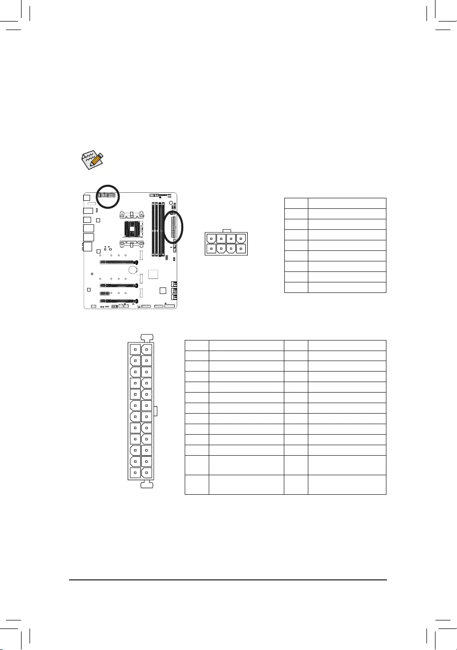
1/2)ATX_12V/ATX_12V1/ATX(2×412VPowerConnectorand2×12MainPowerConnector)
With the use of the power connector, the power supply can supply enough stable power to all the components
on the motherboard. Before connecting the power connector, rst make sure the power supply is turned
off and all devices are properly installed. The power connector possesses a foolproof design. Connect the
power supply cable to the power connector in the correct orientation.
The 12V power connector mainly supplies power to the CPU. If the 12V power connector is not connected,
the computer will not start.
To meet expansion requirements, it is recommended that a power supply that can withstand high
power consumption be used (500W or greater). If a power supply is used that does not provide the
required power, the result can lead to an unstable or unbootable system.
131
2412
ATX
ATX_12V/ATX_12V1:
Pin No. Denition
1 GND (Only for 2×4-pin 12V)
2 GND (Only for 2×4-pin 12V)
3 GND
4 GND
5 +12V (Only for 2×4-pin 12V)
6 +12V (Only for 2×4-pin 12V)
7 +12V
8 +12V
ATX:
Pin No. Denition Pin No. Denition
1 3.3V 13 3.3V
2 3.3V 14 -12V
3 GND 15 GND
4 +5V 16 PS_ON (soft On/Off)
5 GND 17 GND
6 +5V 18 GND
7 GND 19 GND
8 Power Good 20 NC
9 5VSB (stand by +5V) 21 +5V
10 +12V 22 +5V
11 +12V (Only for 2×12-pin
ATX)
23 +5V (Only for 2×12-pin ATX)
12 3.3V (Only for 2×12-pin
ATX)
24 GND (Only for 2×12-pin ATX)
ATX_12V/ATX_12V1
8
4
5
1
— 27 —
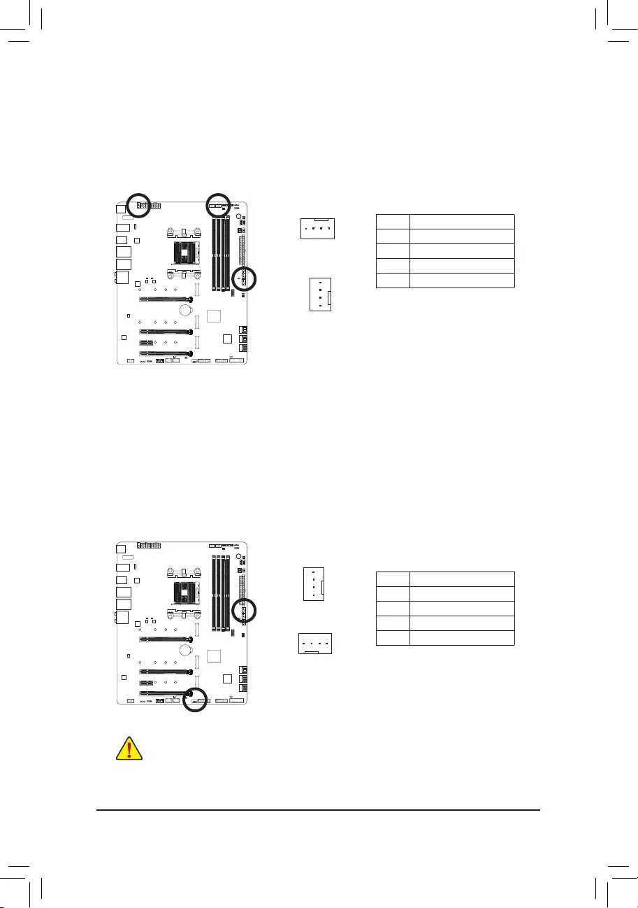
3/4) CPU_FAN/SYS_FAN1/2/4 (Fan Headers)
All fan headers on this motherboard are 4-pin. Most fan headers possess a foolproof insertion design.
When connecting a fan cable, be sure to connect it in the correct orientation (the black connector wire
is the ground wire). The motherboard supports CPU fan speed control, which requires the use of a CPU
fan with fan speed control design. For optimum heat dissipation, it is recommended that a system fan be
installed inside the chassis.
Pin No. Denition
1 GND
2 Voltage Speed Control
3 Sense
4 PWM Speed Control
SYS_FAN1/SYS_FAN2/SYS_FAN4
1
1
CPU_FAN
5) SYS_FAN5_PUMP/SYS_FAN6_PUMP (System Fan/Water Cooling Pump Headers)
The fan/pump headers are 4-pin. Most fan headers possess a foolproof insertion design. When connecting
a fan cable, be sure to connect it in the correct orientation (the black connector wire is the ground wire).
The speed control function requires the use of a fan with fan speed control design. For optimum heat dis-
sipation, it is recommended that a system fan be installed inside the chassis. The header also provides
speed control for a water cooling pump, refer to Chapter 2, «BIOS Setup,» «Settings\Smart Fan 5,» for more
information.
Pin No. Denition
1 GND
2 Voltage Speed Control
3 Sense
4 PWM Speed Control
1
•Be sure to connect fan cables to the fan headers to prevent your CPU and system from overheat—
ing. Overheating may result in damage to the CPU or the system may hang.
•These fan headers are not conguration jumper blocks. Do not place a jumper cap on the headers.
1
SYS_FAN6_PUMP
SYS_FAN5_PUMP
— 28 —
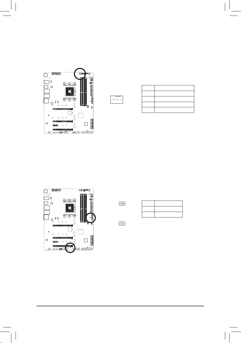
6) CPU_OPT (Water Cooling CPU Fan Header)
The fan header is 4-pin and possesses a foolproof insertion design. Most fan headers possess a foolproof
insertion design. When connecting a fan cable, be sure to connect it in the correct orientation (the black
connector wire is the ground wire). The speed control function requires the use of a fan with fan speed
control design.
1
Pin No. Denition
1 GND
2 Voltage Speed Control
3 Sense
4 PWM Speed Control
7) EC_TEMP1/EC_TEMP2 (Temperature Sensor Headers)
Connect the thermistor cables to the headers for temperature detection.
Pin No. Denition
1 SENSOR IN
2 GND
1
EC_TEMP1
1
EC_TEMP2
— 29 —
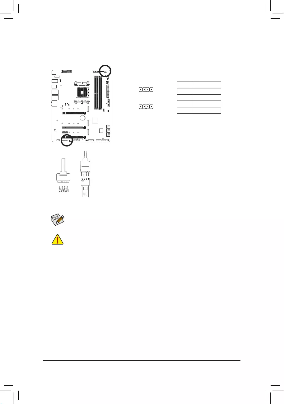
LED_C1/LED_C2 (RGB LED Strip Headers)
The headers can be used to connect a standard 5050 RGB LED strip (12V/G/R/B), with maximum power
rating of 2A (12V) and maximum length of 2m.
Pin No. Denition
1 12V
2 G
3 R
4 B
1
1
Connect one end of the RGB LED strip extension cable to the header
and the other end to your RGB LED strip. The black wire (marked
with a triangle on the plug) of the extension cable must be connected
to Pin 1 (12V) of this header. The 12V pin (marked with an arrow) on
the other end of the extension cable must be lined up with the 12V of
the LED strip. Be careful with the connection orientation of the LED
strip; incorrect connection may lead to the damage of the LED strip.
12VRGB
12V
1
RGB LED
Strip
BG12VR
Before installing the devices, be sure to turn off the devices and your computer. Unplug the power
cord from the power outlet to prevent damage to the devices.
For how to turn on/off the lights of the LED strip, refer to the instructions on in Chapter 5, «Unique
Features,» «APP Center\RGB Fusion.»
LED_C1
LED_C2
— 30 —
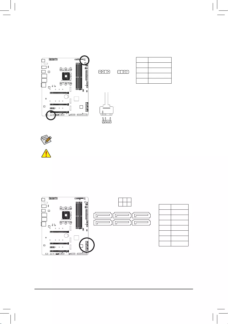
9) D_LED1/D_LED2 (Addressable LED Strip Headers)
The headers can be used to connect a standard 5050 addressable LED strip, with maximum power rating
of 5A (5V) and maximum number of 1000 LEDs.
Pin No. Denition
1 V
2 D
3 No Pin
4 G
1
Before installing the devices, be sure to turn off the devices and your computer. Unplug the power
cord from the power outlet to prevent damage to the devices.
For how to turn on/off the lights of the LED strip, refer to the instructions on in Chapter 5, «Unique
Features,» «APP Center\RGB Fusion.»
D_LED1 D_LED2
1
F_USB30 F_U
B_
F_ F_
_
B
BS_
B
SB_
B
_S
S_
_
B
_U
_
B
S
123
123
123
123
1
1
1
1
BSS
S
_S
SSU
1 2 3 4 5
S3 BSSS
U
__ 3
F_USB3F
S _
S _
S _
SF
B_
B_
F
_0
S
S
_0F
_F
_
_
__B
U
S _S
_ SF_
USB0_B
B_ F_USB3
F_USB303
_
_3U
S_
F_USB30 F_U
B_
F_ F_
_
B
BS_
B
SB_
B
_S
S_
_
B
_U
_
B
S
123
123
123
123
1
1
1
1
BSS
S
_S
SSU
1 2 3 4 5
S3 BSSS
U
__ 3
F_USB3F
S _
S _
S _
SF
B_
B_
F
_0
S
S
_0F
_F
_
_
__B
U
S _S
_ SF_
USB0_B
B_ F_USB3
F_USB303
_
_3U
S_
Connect your addressable LED strip
to the header. The power pin (marked
with a triangle on the plug) of the LED
strip must be connected to Pin 1 of the
addressable LED strip header. Incorrect
connection may lead to the damage of
the LED strip.
Addressable
LED strip
adapter cable
1
10) SATA3 0/1/2/3/4/5 (SATA 6Gb/s Connectors)
The SATA connectors conform to SATA 6Gb/s standard and are compatible with SATA 3Gb/s and SATA
1.5Gb/s standard. Each SATA connector supports a single SATA device. The SATA connectors support
RAID 0, RAID 1, and RAID 10. Refer to Chapter 3, «Conguring a RAID Set,» for instructions on conguring
a RAID array.
71
71
SATA3
420
531 Pin No. Denition
1 GND
2 TXP
3 TXN
4 GND
5 RXN
6 RXP
7 GND
— 31 —
11) M2A_SOCKET/M2B_SOCKET/M2C_SOCKET (M.2 Socket 3 Connectors)
The M.2 connectors support M.2 SATA SSDs or M.2 PCIe SSDs and support RAID conguration. Please
note that an M.2 PCIe SSD cannot be used to create a RAID set with a SATA hard drive. To create a RAID
array with an M.2 PCIe SSD, you must set up the conguration in UEFI BIOS mode. Refer to Chapter 3,
«Conguring a RAID Set,» for instructions on conguring a RAID array.
F_USB30 F_U
B_
F_ F_
_
B
BS_
B
SB_
B
_S
S_
_
B
_U
_
B
S
123
123
123
123
1
1
1
1
BSS
S
_S
SSU
1 2 3 4 5
S3 BSSS
U
__ 3
F_USB3F
S _
S _
S _
SF
B_
B_
F
_0
S
S
_0F
_F
_
_
__B
U
S _S
_ SF_
USB0_B
B_ F_USB3
F_USB303
_
_3U
S_
80110 60
M2B_SOCKET
F_USB30 F_U
B_
F_ F_
_
B
BS_
B
SB_
B
_S
S_
_
B
_U
_
B
S
123
123
123
123
1
1
1
1
BSS
S
_S
SSU
1 2 3 4 5
S3 BSSS
U
__ 3
F_USB3F
S _
S _
S _
SF
B_
B_
F
_0
S
S
_0F
_F
_
_
__B
U
S _S
_ SF_
USB0_B
B_ F_USB3
F_USB303
_
_3U
S_
80 60
M2C_SOCKET
42
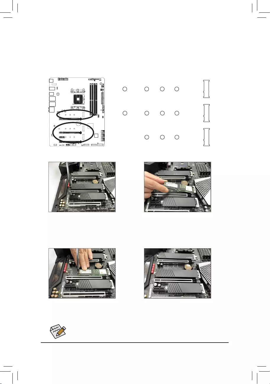
Follow the steps below to correctly install an M.2 SSD in the M.2 connector.
Select the proper hole for the M.2 SSD to be installed and refasten the screw and standoff.
F_USB30 F_U
B_
F_ F_
_
B
BS_
B
SB_
B
_S
S_
_
B
_U
_
B
S
123
123
123
123
1
1
1
1
BSS
S
_S
SSU
1 2 3 4 5
S3 BSSS
U
__ 3
F_USB3F
S _
S _
S _
SF
B_
B_
F
_0
S
S
_0F
_F
_
_
__B
U
S _S
_ SF_
USB0_B
B_ F_USB3
F_USB303
_
_3U
S_
80110 60
M2A_SOCKET
42
42
Step 1:
Get a screw and a standoff from the included M.2
screw and standoff packs. Locate the M.2 con-
nector where you will install the M.2 SSD, use a
screwdriver to unfasten the screw on the heatsink
and then remove the heatsink.
Step 3:
Press the M.2 SSD down and then secure it with
the screw. Replace the heatsink and secure it to
the original hole.
Step 4:
The installation is completed, as shown in the
picture above.
Step 2:
Locate the proper mounting hole for the M.2
SSD to be installed and then tighten the standoff
rst. Insert the M.2 SSD into the M.2 connector
at an angle.
— 32 —
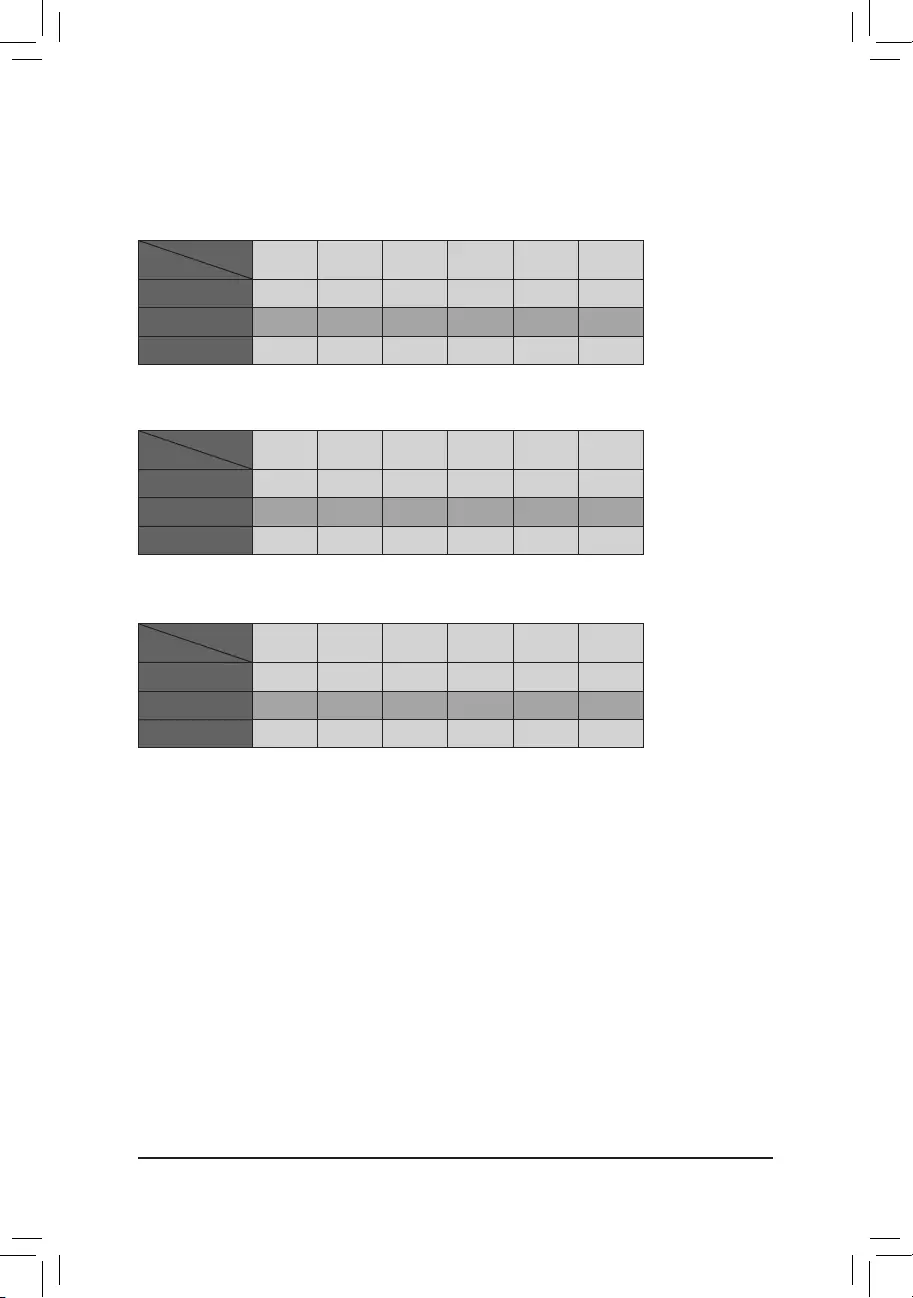
•M2A_SOCKET:
SATA3 0 SATA3 1 SATA3 2 SATA3 3 SATA3 4 SATA3 5
M.2 SATA SSD aaaaaa
M.2 PCIe SSD
aaaaaa
No M.2 SSD Installed aaaaaa
a: Available, r: Not available
Connector
Type of
M.2 SSD
Installation Notices for the M.2 and SATA Connectors:
The availability of the SATA connectors may be affected by the type of device installed in the M.2 sockets. The
M2C_SOCKET connector shares bandwidth with the SATA3 4/5 connector. Refer to the following tables for details.
•M2B_SOCKET:
SATA3 0 SATA3 1 SATA3 2 SATA3 3 SATA3 4 SATA3 5
M.2 SATA SSD aaaaaa
M.2 PCIe SSD
aaaaaa
No M.2 SSD Installed aaaaaa
a: Available, r: Not available
Connector
Type of
M.2 SSD
•M2C_SOCKET:
SATA3 0 SATA3 1 SATA3 2 SATA3 3 SATA3 4 SATA3 5
M.2 SATA SSD aaaaaa
M.2 PCIe SSD
aaaar r
No M.2 SSD Installed aaaaaa
a: Available, r: Not available
Connector
Type of
M.2 SSD
— 33 —
The front panel design may differ by chassis. A front panel module mainly consists of power switch,
reset switch, power LED, hard drive activity LED, speaker and etc. When connecting your chassis
front panel module to this header, make sure the wire assignments and the pin assignments are
matched correctly.
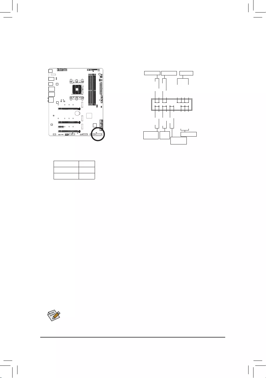
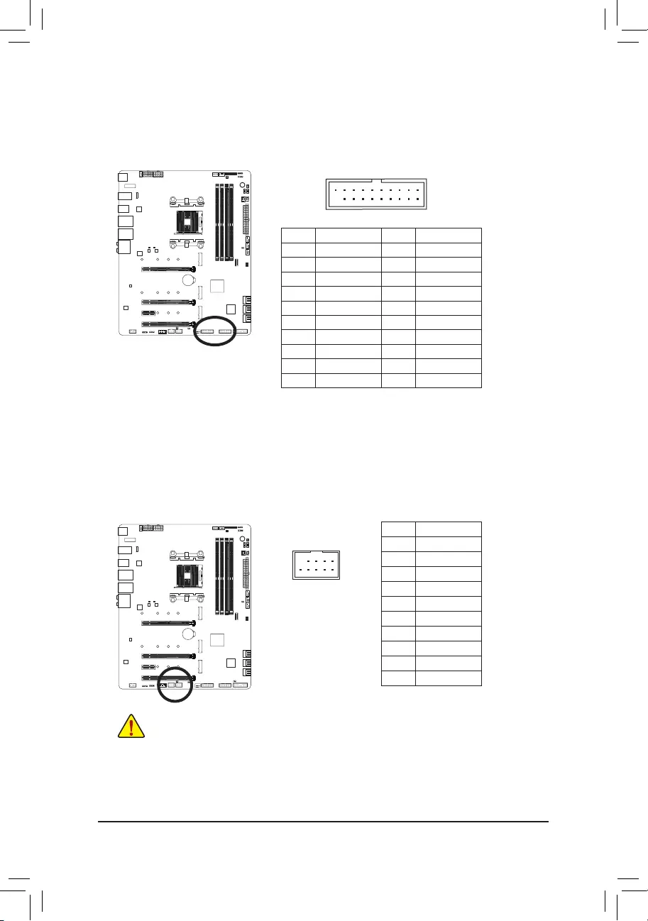
12) F_PANEL (Front Panel Header)
Connect the power switch, reset switch, speaker, chassis intrusion switch/sensor and system status indicator
on the chassis to this header according to the pin assignments below. Note the positive and negative pins
before connecting the cables.
System Status LED
S0 On
S3/S4/S5 Off
•PW (Power Switch):
Connects to the power switch on the chassis front panel. You may congure the way to turn off your
system using the power switch (refer to Chapter 2, «BIOS Setup,» «Settings\Platform Power,» for more
information).
•SPEAK (Speaker):
Connects to the speaker on the chassis front panel. The system reports system startup status by issuing
a beep code. One single short beep will be heard if no problem is detected at system startup.
•HD (Hard Drive Activity LED):
Connects to the hard drive activity LED on the chassis front panel. The LED is on when the hard drive
is reading or writing data.
•RES (Reset Switch):
Connects to the reset switch on the chassis front panel. Press the reset switch to restart the computer
if the computer freezes and fails to perform a normal restart.
•CI (Chassis Intrusion Header):
Connects to the chassis intrusion switch/sensor on the chassis that can detect if the chassis cover has
been removed. This function requires a chassis with a chassis intrusion switch/sensor.
•NC: No connection.
•PLED/PWR_LED (Power LED):
Connects to the power status indicator on the chassis front panel. The LED
is on when the system is operating. The LED is off when the system is in S3/
S4 sleep state or powered off (S5).
Power LED
1
2
19
20
CI-
CI+
PWR_LED+
PLED-
PW-
SPEAK+
SPEAK-
PLED+
PW+
HD-
RES+
HD+
RES-
Hard Drive
Activity LED
Reset
Switch Chassis Intru-
sion Header
Power Switch Speaker
PWR_LED-
PWR_LED-
Power LED
NC
NC
— 34 —
13) F_AUDIO (Front Panel Audio Header)
ThefrontpanelaudioheadersupportsHighDenitionaudio(HD).Youmayconnectyourchassisfront
panelaudiomoduletothisheader.Makesurethewireassignmentsofthemoduleconnectormatchthe
pinassignmentsofthemotherboardheader.Incorrectconnectionbetweenthemoduleconnectorandthe
motherboardheaderwillmakethedeviceunabletoworkorevendamageit.
PinNo. Denition
1MIC2_L
2GND
3MIC2_R
4NC
5LINE2_R
6 Sense
7 GND
8 No Pin
9LINE2_L
10 Sense
F_USB30 F_U
B_
F_ F_
_
B
BS_
B
SB_
B
_S
S_
_
B
_U
_
B
S
123
123
123
123
1
1
1
1
BSS
S
_S
SSU
1 2 3 4 5
S3 BSSS
U
__ 3
F_USB3F
S _
S _
S _
SF
B_
B_
F
_0
S
S
_0F
_F
_
_
__B
U
S _S
_ SF_
USB0_B
B_ F_USB3
F_USB303
_
_3U
S_
9 1
10 2
Somechassisprovideafrontpanelaudiomodulethathasseparatedconnectorsoneachwire
insteadofasingleplug.Forinformationaboutconnectingthefrontpanelaudiomodulethathas
differentwireassignments,pleasecontactthechassismanufacturer.
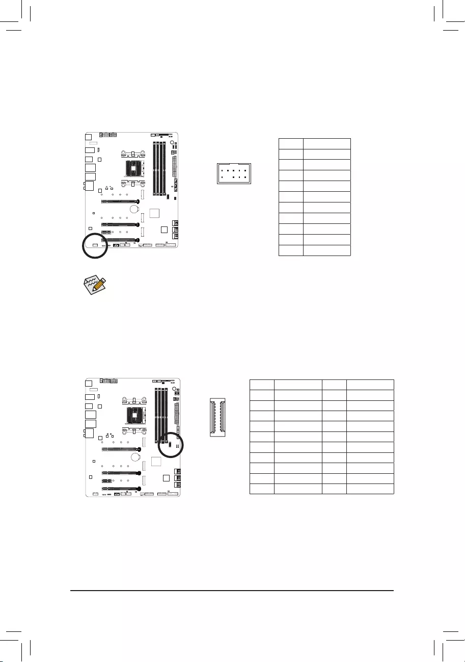
PinNo. Denition PinNo. Denition
1 VBUS 11 VBUS
2TX1+ 12 TX2+
3 TX1- 13 TX2-
4 GND 14 GND
5RX1+ 15 RX2+
6RX1- 16 RX2-
7 VBUS 17 GND
8CC1 18 D-
9 SBU1 19 D+
10 SBU2 20 CC2
14) F_USB31C (USB Type-C™ Header with USB 3.1 Gen 2 Support)
TheheaderconformstoUSB3.1Gen2specicationandcanprovideoneUSBport.
F_USB30 F_U
B_
F_ F_
_
B
BS_
B
SB_
B
_S
S_
_
B
_U
_
B
S
123
123
123
123
1
1
1
1
BSS
S
_S
SSU
1 2 3 4 5
S3 BSSS
U
__ 3
F_USB3F
S _
S _
S _
SF
B_
B_
F
_0
S
S
_0F
_F
_
_
__B
U
S _S
_ SF_
USB0_B
B_ F_USB3
F_USB303
_
_3U
S_
20
10 11
1
— 35 —
15) F_USB30_1/F_USB30_2 (USB 3.1 Gen 1 Headers)
The headers conform to USB 3.1 Gen 1 and USB 2.0 specication and each header can provide two USB
ports. For purchasing the optional 3.5″ front panel that provides two USB 3.1 Gen 1 ports, please contact
the local dealer.
Pin No. Denition Pin No. Denition
1 VBUS 11 D2+
2 SSRX1- 12 D2-
3 SSRX1+ 13 GND
4 GND 14 SSTX2+
5 SSTX1- 15 SSTX2-
6 SSTX1+ 16 GND
7 GND 17 SSRX2+
8 D1- 18 SSRX2-
9 D1+ 19 VBUS
10 NC 20 No Pin
20
110
11
F_USB30 F_U
B_
F_ F_
_
B
BS_
B
SB_
B
_S
S_
_
B
_U
_
B
S
123
123
123
123
1
1
1
1
BSS
S
_S
SSU
1 2 3 4 5
S3 BSSS
U
__ 3
F_USB3F
S _
S _
S _
SF
B_
B_
F
_0
S
S
_0F
_F
_
_
__B
U
S _S
_ SF_
USB0_B
B_ F_USB3
F_USB303
_
_3U
16) F_USB1/F_USB2 (USB 2.0/1.1 Headers)
The headers conform to USB 2.0/1.1 specication. Each USB header can provide two USB ports via an
optional USB bracket. For purchasing the optional USB bracket, please contact the local dealer.
Pin No. Denition
1 Power (5V)
2 Power (5V)
3 USB DX-
4 USB DY—
5 USB DX+
6 USB DY+
7 GND
8 GND
9 No Pin
10 NC
10
9
2
1
•Only the USB ports routed to the F_USB30_1 connector support USB TurboCharger. Enabling
this function requires software support. The maximum power output of this connector may vary
depending on the power management mechanism for the USB cable and charging device used.
For more information on USB TurboCharger, refer to the instructions in Chapter 5, «Unique
Features.»
•Do not plug the IEEE 1394 bracket (2×5-pin) cable into the USB 2.0/1.1 header.
•Prior to installing the USB bracket, be sure to turn off your computer and unplug the power cord
from the power outlet to prevent damage to the USB bracket.
— 36 —
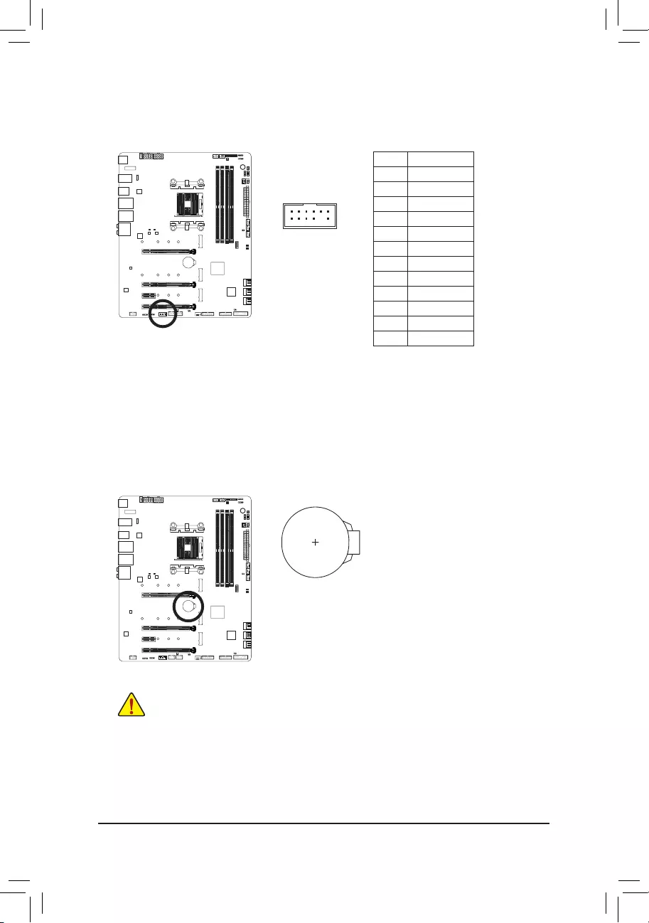
17) TPM (Trusted Platform Module Header)
You may connect a TPM (Trusted Platform Module) to this header.
11 1
F_USB30 F_U
B_
F_ F_
_
B
BS_
B
SB_
B
_S
S_
_
B
_U
_
B
S
123
123
123
123
1
1
1
1
BSS
S
_S
SSU
1 2 3 4 5
S3 BSSS
U
__ 3
F_USB3F
S _
S _
S _
SF
B_
B_
F
_0
S
S
_0F
_F
_
_
__B
U
S _S
_ SF_
USB0_B
B_ F_USB3
F_USB303
_
_3U
S_
Pin No. Denition
1 LAD0
2 VCC3
3 LAD1
4 No Pin
5 LAD2
6 LCLK
7 LAD3
8 GND
9 LFRAME
10 NC
11 SERIRQ
12 LRESET
12 2
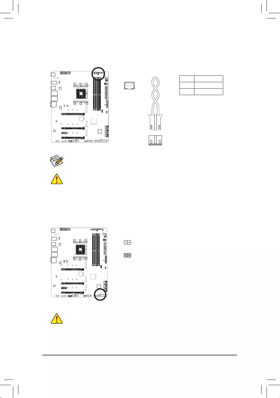
18) BAT (Battery)
The battery provides power to keep the values (such as BIOS congurations, date, and time information)
in the CMOS when the computer is turned off. Replace the battery when the battery voltage drops to a low
level, or the CMOS values may not be accurate or may be lost.
You may clear the CMOS values by removing the battery:
1. Turn off your computer and unplug the power cord.
2. Gently remove the battery from the battery holder and wait for one minute.
(Or use a metal object like a screwdriver to touch the positive and nega—
tive terminals of the battery holder, making them short for 5 seconds.)
3. Replace the battery.
4. Plug in the power cord and restart your computer.
•Always turn off your computer and unplug the power cord before replacing the battery.
•Replace the battery with an equivalent one. Damage to your devices may occur if the battery is
replaced with an incorrect model.
•Contact the place of purchase or local dealer if you are not able to replace the battery by yourself
or uncertain about the battery model.
•When installing the battery, note the orientation of the positive side (+) and the negative side (-)
of the battery (the positive side should face up).
•Used batteries must be handled in accordance with local environmental regulations.
— 37 —
19) NOISE SENSOR (Noise Detection Header)
This header can be used to connect a noise detection cable to detect the noise inside the case.
Pin No. Denition
1 Noise Detection
2 GND
1
Before connecting the cable to the header, make sure to remove the jumper cap; re-place the
jumper cap if the header is not in use.
For more information on the noise detection function, refer to the instructions in Chapter 5, «Unique
Features,» «APP Center\System Information Viewer.»
Noise Detection
Cable
1
20) CLR_CMOS (Clear CMOS Jumper)
Use this jumper to clear the BIOS conguration and reset the CMOS values to factory defaults. To clear
the CMOS values, use a metal object like a screwdriver to touch the two pins for a few seconds.
•Always turn off your computer and unplug the power cord from the power outlet before clearing
the CMOS values.
•After system restart, go to BIOS Setup to load factory defaults (select Load Optimized Defaults) or
manually congure the BIOS settings (refer to Chapter 2, «BIOS Setup,» for BIOS congurations).
Open: Normal
Short: Clear CMOS Values

— 38 —

— 39 —
BIOS (Basic Input and Output System) records hardware parameters of the system in the CMOS on the
motherboard. Its major functions include conducting the Power-On Self-Test (POST) during system startup,
saving system parameters and loading operating system, etc. BIOS includes a BIOS Setup program that allows
theusertomodifybasicsystemcongurationsettingsortoactivatecertainsystemfeatures.
When the power is turned off, the battery on the motherboard supplies the necessary power to the CMOS to
keepthecongurationvaluesintheCMOS.
To access the BIOS Setup program, press the <Delete> key during the POST when the power is turned on.
To upgrade the BIOS, use either the GIGABYTE Q-Flash or @BIOS utility.
•Q-Flash allows the user to quickly and easily upgrade or back up BIOS without entering the operating system.
•@BIOS is a Windows-based utility that searches and downloads the latest version of BIOS from the Internet
and updates the BIOS.
For instructions on using the Q-Flash and @BIOS utilities, refer to Chapter 5, «BIOS Update Utilities.»
Chapter 2 BIOS Setup
•BecauseBIOSashingispotentiallyrisky,ifyoudonotencounterproblemsusingthecurrent
versionofBIOS,it isrecommendedthatyounotashthe BIOS.ToashtheBIOS, doitwith
caution.InadequateBIOSashingmayresultinsystemmalfunction.
•It is recommended that you not alter the default settings (unless you need to) to prevent system
instability or other unexpected results. Inadequately altering the settings may result in system’s
failure to boot. If this occurs, try to clear the CMOS values and reset the board to default values.
(Refer to the «Load Optimized Defaults» section in this chapter or introductions of the battery or the
clear CMOS jumper/button in Chapter 1 for how to clear the CMOS values.)

— 40 —
2-1 Startup Screen
The following startup Logo screen will appear when the computer boots.
Function Keys:
<DEL>: BIOS SETUP\Q-FLASH
Press the <Delete> key to enter BIOS Setup or to access the Q-Flash utility in BIOS Setup.
<F9>: SYSTEM INFORMATION
Press the <F9> key to display your system information.
<F12>: BOOT MENU
BootMenuallowsyoutosettherstbootdevicewithoutenteringBIOSSetup.InBootMenu,usetheup
arrow key <h> or the down arrow key <i>toselecttherstbootdevice,thenpress<Enter>toaccept.
The system will boot from the device immediately.
Note: The setting in Boot Menu is effective for one time only. After system restart, the device boot order
will still be based on BIOS Setup settings.
<END>: Q-FLASH
Pressthe<End>keytoaccesstheQ-FlashutilitydirectlywithouthavingtoenterBIOSSetuprst.
Function Keys
— 41 —
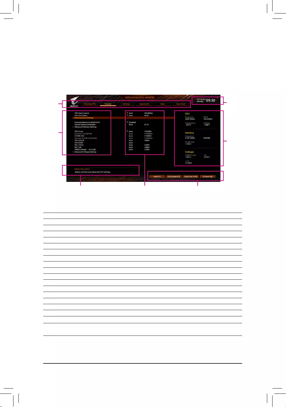
2-2 The Main Menu
Advanced Mode
The Advanced Mode mode provides detailed BIOS settings. You can press the arrow keys on your keyboard
to move among the items and press <Enter> to accept or enter a sub-menu. Or you can use your mouse to
select the item you want.
(Sample BIOS Version: D15)
Advanced Mode Function Keys
<f><g>Move the selection bar to select a setup menu
<h><i>Movetheselectionbartoselectancongurationitemonamenu
<Enter>/Double Click Execute command or enter a menu
<+>/<Page Up> Increase the numeric value or make changes
<->/<Page Down> Decrease the numeric value or make changes
<F1> Show descriptions of the function keys
<F2> Switch to Easy Mode
<F3> SavethecurrentBIOSsettingstoaprole
<F4> LoadtheBIOSsettingsfromaprolecreatedbefore
<F5> Restore the previous BIOS settings for the current submenus
<F6> Display the Smart Fan 5 screen
<F7> Load the Optimized BIOS default settings for the current submenus
<F8> Access the Q-Flash utility
<F10> Save all the changes and exit the BIOS Setup program
<F11> Switch to the Favorites submenu
<F12> Capture the current screen as an image and save it to your USB drive
<Insert> Add or remove a favorite option
<Ctrl>+<S> Display information on the installed memory.
<Esc> Main Menu: Exit the BIOS Setup program
Submenus: Exit current submenu
Hardware
Information
Option Description Current Settings
Setup
Menus
System
Time
Quick Access Bar allows you to enter Help, Easy
Mode, Smart Fan 5, or Q-Flash.
Conguration
Items
— 42 —
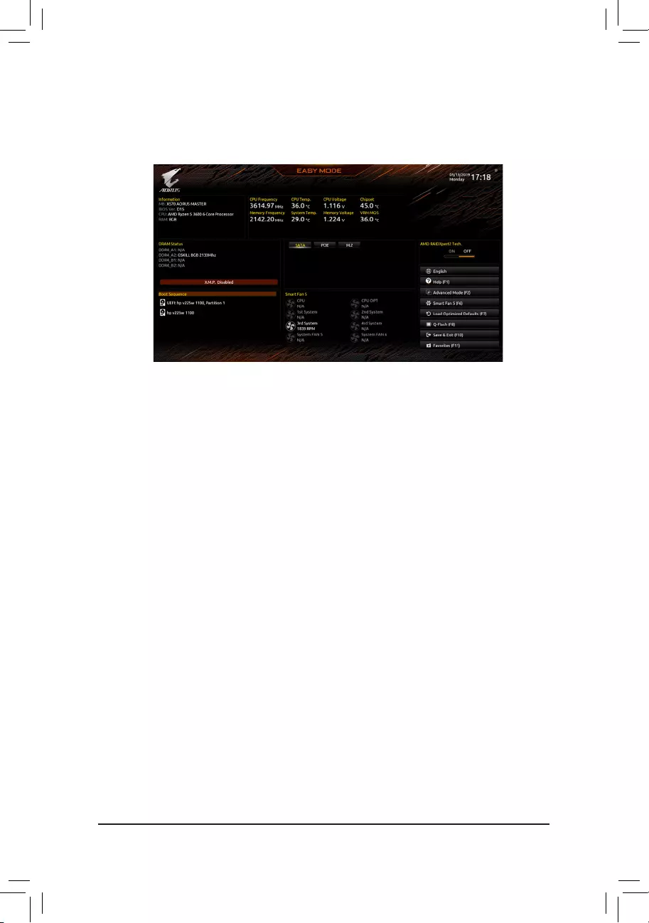
B. Easy Mode
Easy Mode allows users to quickly view their current system information or to make adjustments for optimum
performance.InEasyMode,youcanuseyourmousetomovethroughcongurationitemsorpress<F2>to
switch to the Advanced Mode screen.

— 43 —
2-3 Favorites (F11)
Set your frequently used options as your favorites and use the <F11> key to quickly switch to the page where
all of your favorite options are located. To add or remove a favorite option, go to its original page and press
<Insert> on the option. The option is marked with a star sign if set as a «favorite.»
— 44 —
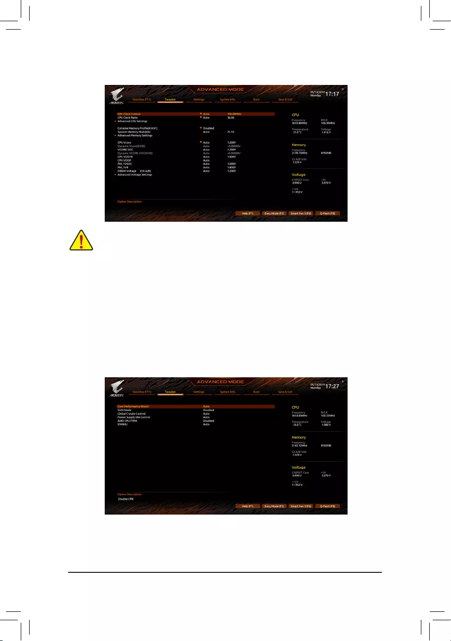
2-4 Tweaker
Whether the system will work stably with the overclock/overvoltage settings you made is dependent
onyouroverallsystemcongurations.Incorrectlydoingoverclock/overvoltagemayresultindamage
to CPU, chipset, or memory and reduce the useful life of these components. This page is for advanced
users only and we recommend you not to alter the default settings to prevent system instability or
other unexpected results. (Inadequately altering the settings may result in system’s failure to boot. If
this occurs, clear the CMOS values and reset the board to default values.)
&CPU Clock Control
Allows you to manually set the CPU base clock in 0.01 MHz increments. (Default: Auto)
Important: ItishighlyrecommendedthattheCPUfrequencybesetinaccordancewiththeCPUspecications.
&CPU Clock Ratio
Allows you to alter the clock ratio for the installed CPU. The adjustable range is dependent on the CPU
being installed.
Advanced CPU Settings
&Core Performance Boost (Note)
Allows you to determine whether to enable the Core Performance Boost (CPB) technology, a CPU
performance-boost technology. (Default: Auto)
(Note) This item is present only when you install a CPU that supports this feature.

— 45 —
&SVM Mode
Virtualization enhanced by Virtualization Technology will allow a platform to run multiple operating systems
and applications in independent partitions. With virtualization, one computer system can function as multiple
virtual systems. (Default: Disabled)
&Global C-state Control (Note 1)
Allows you to determine whether to let the CPU enter C states. When enabled, the CPU core frequency
will be reduced during system halt state to decrease power consumption. (Default: Auto)
&Power Supply Idle Control (Note 1)
Enables or disables
Package C6 State.
Typical Current Idle Disables this function.
Low Current Idle Enables this function.
Auto
LetstheBIOSautomaticallycongurethissetting.
(Default)
&AMD CPU fTPM
Enables or disables the TPM 2.0 function integrated in the AMD CPU. (Default: Disabled)
&IOMMU (Note 1)
Enables or disables AMD IOMMU support. (Default: Auto)
&ExtremeMemoryProle(X.M.P.)(Note 2)
Allows the BIOS to read the SPD data on XMP memory module(s) to enhance memory performance when
enabled.
Disabled Disables this function. (Default)
Prole1 UsesProle1settings.
Prole2(Note 2) UsesProle2settings.
&System Memory Multiplier
Allows you to set the system memory multiplier. Auto sets memory multiplier according to memory SPD
data. (Default: Auto)
(Note 1) This item is present only when you install a CPU that supports this feature.
(Note 2) This item is present only when you install a CPU and a memory module that support this feature.

— 46 —
Advanced Memory Settings
&Memory Timing Mode
Manual allows the memory timing settings on the Memory Subtimingssubmenu to be congurable.
Options are: Auto (default), Manual.
&CLDO_VDDP Control (Note)
Allows you to determine whether to manually change the CLDO_VDDP voltage. Auto lets the BIOS
automaticallycongurethissetting.(Default:Auto)
&CLDO_VDDP Voltage(mV) (Note)
AllowsyoutomanuallychangetheCLDO_VDDPvoltage.ThisitemiscongurableonlywhenCLDO_VDDP
Control is set to Manual.
SPD Info
Displays information on the installed memory.
Memory Subtimings
d Standard Timing Control, Advanced Timing Control, CAD Bus Setup Timing, CAD Bus
DriveStrength,DataBusConguration
Thesesectionsprovidememorytimingsettings.Therespectivetimingsettingscreensarecongurable
only when Memory Timing Mode is set to Manual. Note: Your system may become unstable or fail to boot
after you make changes on the memory timings. If this occurs, please reset the board to default values by
loading optimized defaults or clearing the CMOS values.
&CPU Vcore/Dynamic Vcore(DVID)/VCORE SOC/Dynamic VCORE SOC(DVID)/CPU VDD18/
CPU VDDP/PM_1VSOC/PM_1V8/DRAM Voltage (CH A/B)
These items allow you to adjust the CPU Vcore and memory voltages.
(Note) This item is present only when you install a CPU that supports this feature.

— 47 —
Advanced Voltage Settings
ThissubmenuallowsyoutocongureLoad-LineCalibrationlevel,over-voltageprotectionlevel,over-current
protection level, and PWM frequency.
— 48 —
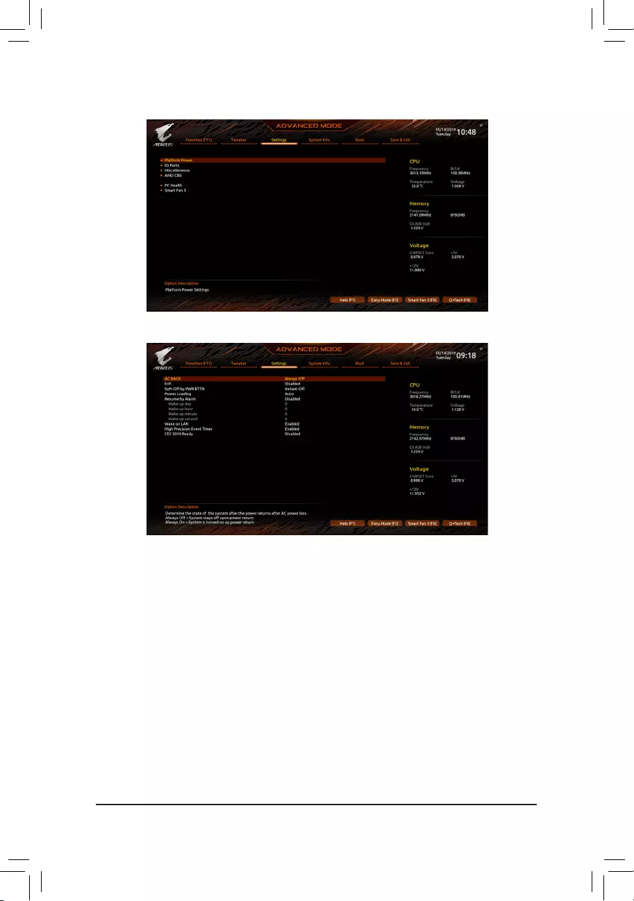
2-5 Settings
Platform Power
&AC BACK
Determines the state of the system after the return of power from an AC power loss.
Always Off The system stays off upon the return of the AC power. (Default)
Always On The system is turned on upon the return of the AC power.
Memory The system returns to its last known awake state upon the return of the AC power.
&ErP
Determines whether to let the system consume least power in S5 (shutdown) state. (Default: Disabled)
Note: When this item is set to Enabled, the following functions will become unavailable: Resume by Alarm,
PME event wake up, power on by mouse, power on by keyboard, and wake on LAN.
&Soft-Off by PWR-BTTN
ConguresthewaytoturnoffthecomputerinMS-DOSmodeusingthepowerbutton.
Instant-Off Press the power button and then the system will be turned off instantly. (Default)
Delay 4 Sec. Press and hold the power button for 4 seconds to turn off the system. If the power
button is pressed for less than 4 seconds, the system will enter suspend mode.
&Power Loading
Enables or disables dummy load. When the power supply is at low load, a self-protection will activate causing
it to shutdown or fail. If this occurs, please set to Enabled. AutoletstheBIOSautomaticallycongurethis
setting. (Default: Auto)
— 49 —
&Resume by Alarm
Determines whether to power on the system at a desired time. (Default: Disabled)
If enabled, set the date and time as following:
Wakeupday:Turnonthesystemataspecictimeoneachdayoronaspecicdayinamonth.
Wake up hour/minute/second: Set the time at which the system will be powered on automatically.
Note: When using this function, avoid inadequate shutdown from the operating system or removal of the
AC power, or the settings may not be effective.
&Wake on LAN
Enables or disables the wake on LAN function. (Default: Enabled)
&High Precision Event Timer
Enables or disables High Precision Event Timer (HPET) in the operating system. (Default: Enabled)
&CEC 2019 Ready
Allows you to select whether to allow the system to adjust power consumption when it is in shutdown, idle,
or standby state in order to comply with the CEC (California Energy Commission) 2019 Standards. (Default:
Disabled)
IO Ports
&Initial Display Output
SpeciestherstinitiationofthemonitordisplayfromthetheinstalledPCIExpressgraphicscard.
PCIe1Slot SetsthegraphicscardonthePCIEX16slotastherstdisplay.(Default)
PCIe2Slot SetsthegraphicscardonthePCIEX8slotastherstdisplay.
PCIe 3 Slot (Note) SetsthegraphicscardonthePCIEX4slotastherstdisplay.
&HD Audio Controller
Enables or disables the onboard audio function. (Default: Enabled)
If you wish to install a 3rd party add-in audio card instead of using the onboard audio, set this item to
Disabled.
&PCIEX16 Bifurcation
Allows you to determine how the bandwidth of the PCIEX16 slot is divided. Options: Auto, PCIE 2×8, PCIE 4×4.
(Default: Auto)
&Above 4G Decoding
Enables or disables 64-bit capable devices to be decoded in above 4 GB address space (only if your system
supports 64-bit PCI decoding). Set to Enabled if more than one advanced graphics card are installed and
their drivers are not able to be launched when entering the operating system (because of the limited 4 GB
memory address space). (Default: Disabled)
(Note) This item is present only when you install a CPU that supports this feature.

— 50 —
&OnBoard LAN1 Controller (Intel® GbE LAN Chip, LAN1)
Enables or disables the Intel® GbE LAN function. (Default: Enabled)
If you wish to install a 3rd party add-in network card instead of using the onboard LAN, set this item to
Disabled.
&OnBoard LAN2 Controller (Realtek® GbE LAN Chip, LAN2)
Enables or disables the Realtek® GbE LAN function. (Default: Enabled)
If you wish to install a 3rd party add-in network card instead of using the onboard LAN, set this item to
Disabled.
&NVMe RAID mode
AllowsyoutodeterminewhethertoenableyourM.2PCIeNVMESSDwhenconguringRAID.(Default:
Disabled)
&Onboard DB Port LED
Allows you to enable or disable the LED lighting of the motherboard debug LEDs when the system is on.
(Default: On)
USBConguration
&Legacy USB Support
Allows USB keyboard/mouse to be used in MS-DOS. (Default: Enabled)
&XHCI Hand-off
Determines whether to enable XHCI Hand-off feature for an operating system without XHCI Hand-off
support. (Default: Enabled)
&USB Mass Storage Driver Support
Enables or disables support for USB storage devices. (Default: Enabled)
&Port 60/64 Emulation
Enables or disables emulation of I/O ports 64h and 60h. This should be enabled for full legacy support
for USB keyboards/mice in MS-DOS or in operating system that does not natively support USB devices.
(Default: Disabled)
&Mass Storage Devices
Displays a list of connected USB mass storage devices. This item appears only when a USB storage device
is installed.
NVMeConguration
Displays information on your M.2 NVME PCIe SSD if installed.
SATAConguration
&SATA Mode
EnablesordisablesRAIDfortheintegratedSATAcontrollersorcongurestheSATAcontrollerstoAHCI
mode.
RAID Enables RAID for the SATA controller.
AHCI CongurestheSATAcontrollerstoAHCImode.AdvancedHostControllerInterface
(AHCI)isaninterfacespecicationthatallowsthestoragedrivertoenableadvanced
Serial ATA features such as Native Command Queuing and hot plug. (Default)
&SATA Port 0/1/2/3/4/5 (SATA3 0, 1, 2, 3, 4, 5 Connectors)
Displays the information of the connected SATA device(s).

— 51 —
Miscellaneous
&LEDs in System Power On State
Allows you to enable or disable motherboard LED lighting when the system is on.
Off Disables the selected lighting mode when the system is on.
On Enables the selected lighting mode when the system is on. (Default)
&LEDs in Sleep, Hibernation, and Soft Off States
Allows you to set the lighting mode of the motherboard LEDs in system S3/S4/S5 state.
ThisitemiscongurablewhenLEDs in System Power On State is set to On.
Off Disables the selected lighting mode when the system enters S3/S4/S5 state. (Default)
On Enables the selected lighting mode when the system enters S3/S4/S5 state.
&Onboard Button Light
Allows you to enable or disable the LED lighting of the Clear CMOS button and power button when the
system is on. (Default: On)
Trusted Computing
Enables or disables Trusted Platform Module (TPM).
&PCIeSlotConguration
Allows you to set the operation mode of the PCI Express slots to Gen 1, Gen 2, Gen 3, or Gen 4. Actual
operationmodeissubjecttothehardwarespecicationofeachslot.Auto lets the BIOS automatically
congurethissetting.(Default:Auto)
&3DMark01 Enhancement
Allows you to determine whether to enhance some legacy benchmark performance. (Default: Disabled)
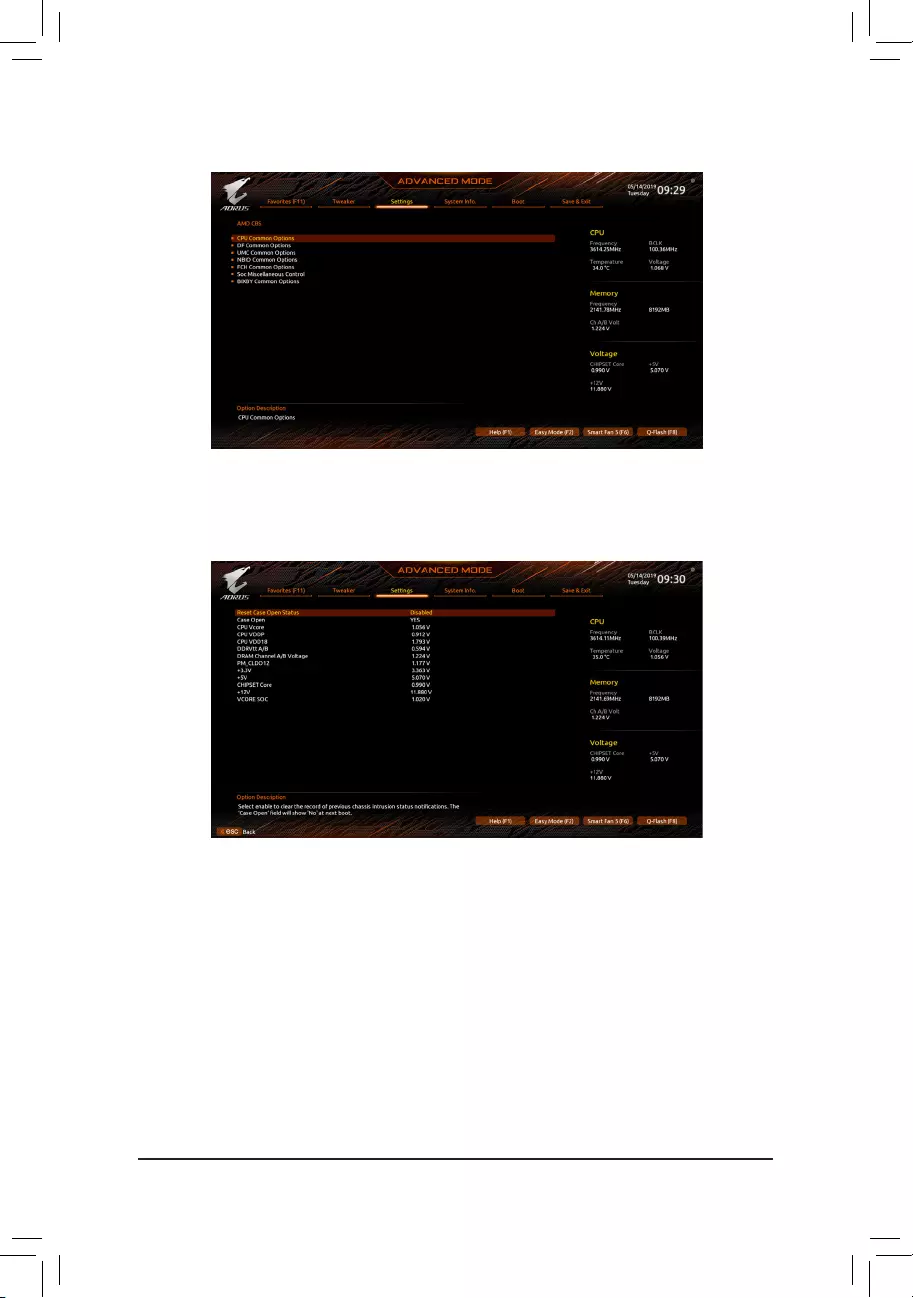
— 52 —
AMD CBS
Thissub-menuprovidesAMDCBS-relatedcongurationoptions.
PC Health
&Reset Case Open Status
Disabled Keeps or clears the record of previous chassis intrusion status. (Default)
Enabled Clears the record of previous chassis intrusion status and the Case Openeldwillshow
«No» at next boot.
&Case Open
Displays the detection status of the chassis intrusion detection device attached to the motherboard CI
header.Ifthesystemchassiscoverisremoved,thiseldwillshow»Yes»,otherwiseitwillshow«No».To
clear the chassis intrusion status record, set Reset Case Open Status to Enabled, save the settings to
the CMOS, and then restart your system.
& CPU Vcore/CPU VDDP/CPU VDD18/DDRVtt A/B/DRAM Channel A/B Voltage/
PM_CLDO12/+3.3V/+5V/CHIPSET Core/+12V/VCORE SOC
Displays the current system voltages.
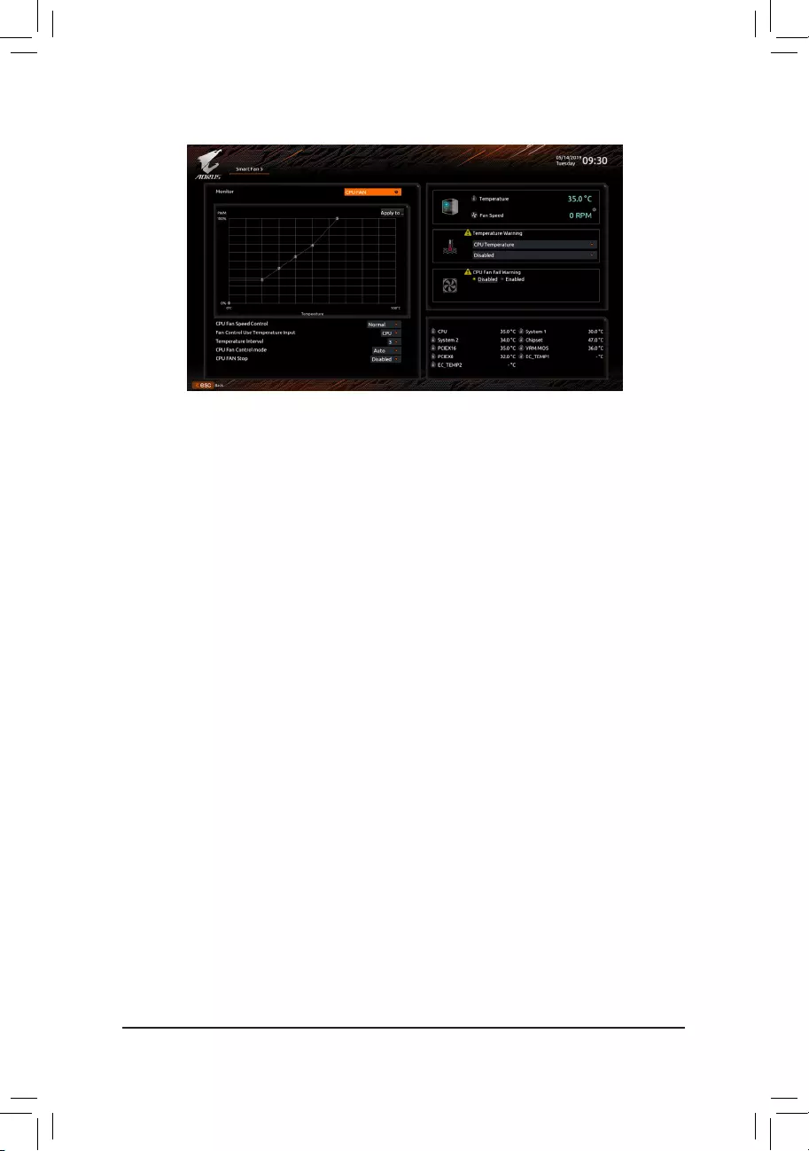
— 53 —
Smart Fan 5
&Monitor
Allows you to select a target to monitor and to make further adjustment. (Default: CPU FAN)
&Fan Speed Control
Allows you to determine whether to enable the fan speed control function and adjust the fan speed.
Normal Allows the fan to run at different speeds according to the temperature. You can adjust
the fan speed with System Information Viewer based on your system requirements.
(Default)
Silent Allows the fan to run at slow speeds.
Manual Allows you to control the fan speed in the curve graph.
Full Speed Allows the fan to run at full speeds.
&Fan Control Use Temperature Input
Allows you to select the reference temperature for fan speed control.
&Temperature Interval
Allows you to select the temperature interval for fan speed change.
&Fan/Pump Control Mode
Auto Lets the BIOS automatically detect the type of fan installed and sets the optimal control
mode. (Default)
Voltage Voltage mode is recommended for a 3-pin fan/pump.
PWM PWM mode is recommended for a 4-pin fan/pump.
&Fan/Pump Stop
Enables or disables the fan/pump stop function. You can set the temperature limit using the temperature
curve. The fan or pump stops operation when the temperature is lower than the limit. (Default: Disabled)
&Temperature
Displays the current temperature of the selected target area.
&Fan Speed
Displays current fan/pump speeds.
&Flow Rate
Displaystheowrateofyourwatercoolingsystem.
&Temperature Warning Control
Sets the warning threshold for temperature. When temperature exceeds the threshold, BIOS will emit
warning sound. Options are: Disabled (default), 60oC/140oF, 70oC/158oF, 80oC/176oF, 90oC/194oF.
&Fan/Pump Fail Warning
Allows the system to emit warning sound if the fan/pump is not connected or fails. Check the fan/pump
condition or fan/pump connection when this occurs. (Default: Disabled)
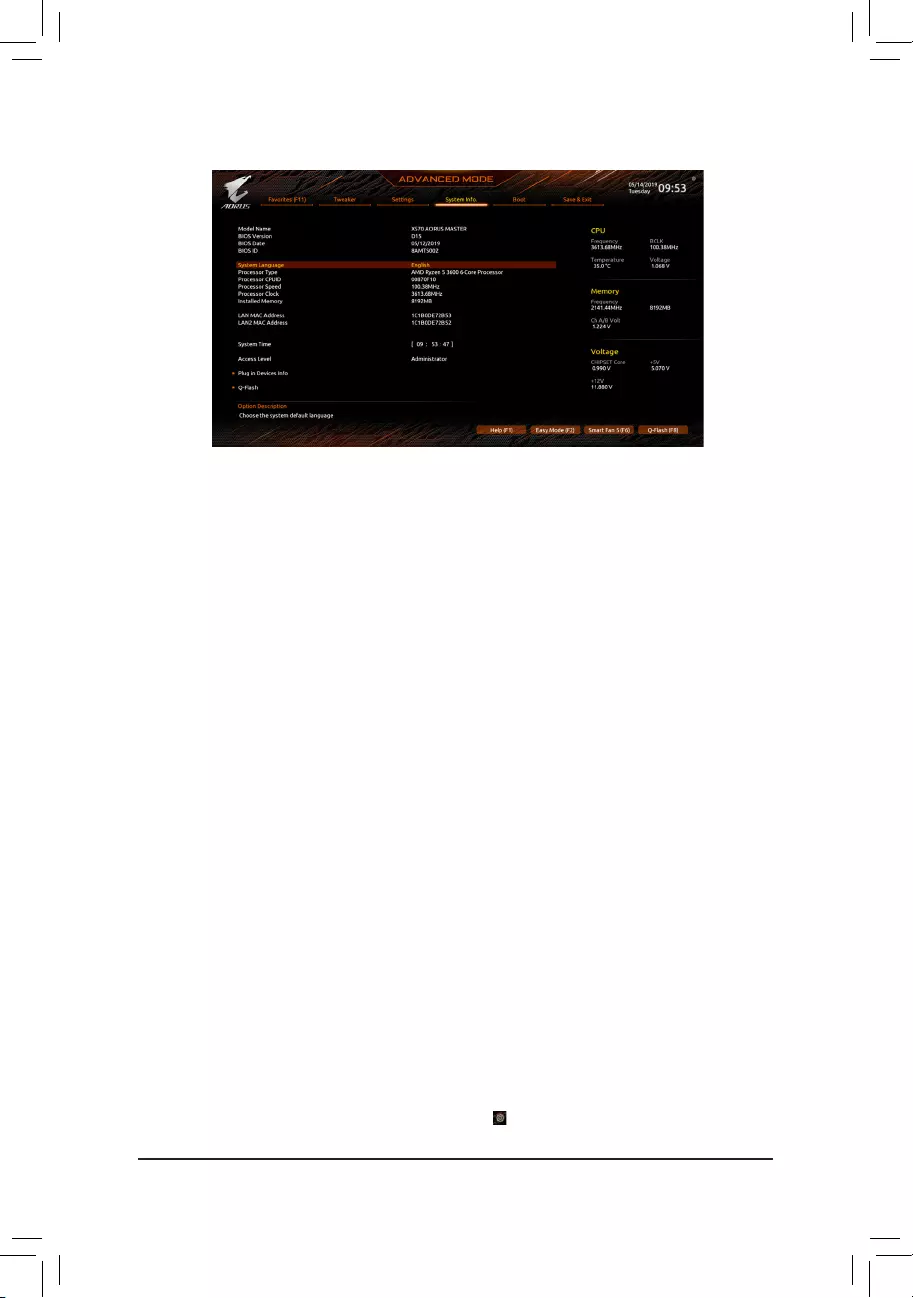
— 54 —
2-6 System Info.
This section provides information on your motherboard model and BIOS version. You can also select the default
language used by the BIOS and manually set the system time.
&System Language
Selects the default language used by the BIOS.
&System Time (Note)
Sets the system time. The time format is hour, minute, and second. For example, 1 p.m. is 13:00:00. Use
<Enter>toswitchbetweentheHour,Minute,andSecondeldsandusethe<PageUp>or<PageDown>
key to set the desired value.
&Access Level
Displays the current access level depending on the type of password protection used. (If no password is
set, the default will display as Administrator.) The Administrator level allows you to make changes to all
BIOS settings; the User level only allows you to make changes to certain BIOS settings but not all.
Plug in Devices Info
Displays information on your SATA, PCI Express, and M.2 devices if installed.
Q-Flash
AllowsyoutoaccesstheQ-FlashutilitytoupdatetheBIOSorbackupthecurrentBIOSconguration.
(Note) To change the system date, right-click the gear icon on the top right corner of the screen for further
settings.

— 55 —
&Boot Option Priorities
Speciestheoverallbootorderfromtheavailabledevices.RemovablestoragedevicesthatsupportGPT
formatwillbeprexedwith»UEFI:»stringonthebootdevicelist.Tobootfromanoperatingsystemthat
supportsGPTpartitioning,selectthedeviceprexedwith»UEFI:»string.
Or if you want to install an operating system that supports GPT partitioning such as Windows 10 64-bit,
selecttheopticaldrivethatcontainstheWindows1064-bitinstallationdiskandisprexedwith«UEFI:»
string.
& Hard Drive/CD/DVD ROM Drive/Floppy Drive/Network Device BBS Priorities
Speciesthebootorderforaspecicdevicetype,suchasharddrives,opticaldrives,oppydiskdrives,
and devices that support Boot from LAN function, etc. Press <Enter> on this item to enter the submenu that
presents the devices of the same type that are connected. This item is present only if at least one device
for this type is installed.
&Bootup NumLock State
Enables or disables Numlock feature on the numeric keypad of the keyboard after the POST. (Default: On)
&Security Option
Specieswhetherapasswordisrequiredeverytimethesystemboots,oronlywhenyouenterBIOSSetup.
Afterconguringthisitem,setthepassword(s)undertheAdministrator Password/User Password item.
Setup A password is only required for entering the BIOS Setup program.
System A password is required for booting the system and for entering the BIOS Setup program.
(Default)
&Full Screen LOGO Show
Allows you to determine whether to display the GIGABYTE Logo at system startup. Disabled skips the
GIGABYTE Logo when the system starts up. (Default: Enabled)
&Fast Boot
Enables or disables Fast Boot to shorten the OS boot process. Ultra Fast provides the fastest bootup
speed. (Default: Disabled)
&SATA Support
Last Boot SATA Devices Only
Except for the previous boot drive, all SATA devices are disabled before
the OS boot process completes. (Default)
All SATA Devices All SATA devices are functional in the operating system and during the POST.
ThisitemiscongurableonlywhenFast Boot is set to Enabled or Ultra Fast.
2-7 Boot

— 56 —
&NVMe Support
Allows you to enable or disable NVMe device(s). (Default: Enabled)
ThisitemiscongurableonlywhenFast Boot is set to Enabled or Ultra Fast.
&VGA Support
Allows you to select which type of operating system to boot.
Auto Enables legacy option ROM only.
EFI Driver Enables EFI option ROM. (Default)
ThisitemiscongurableonlywhenFast Boot is set to Enabled or Ultra Fast.
&USB Support
Disabled All USB devices are disabled before the OS boot process completes.
Full Initial All USB devices are functional in the operating system and during the POST.
(Default)
Partial Initial Part of the USB devices are disabled before the OS boot process completes.
ThisitemiscongurableonlywhenFast Boot is set to Enabled. This function is disabled when Fast Boot
is set to Ultra Fast.
&NetWork Stack Driver Support
Disabled Disables booting from the network. (Default)
Enabled Enables booting from the network.
ThisitemiscongurableonlywhenFast Boot is set to Enabled or Ultra Fast.
&CSM Support
Enables or disables UEFI CSM (Compatibility Support Module) to support a legacy PC boot process.
Enabled Enables UEFI CSM. (Default)
Disabled Disables UEFI CSM and supports UEFI BIOS boot process only.
&LAN PXE Boot Option ROM
Allows you to select whether to enable the legacy option ROM for the LAN controller. (Default: Disabled)
ThisitemiscongurableonlywhenCSM Support is set to Enabled.
&Storage Boot Option Control
Allows you to select whether to enable the UEFI or legacy option ROM for the storage device controller.
Do not launch Disables option ROM.
UEFI Only Enables UEFI option ROM only.
Legacy Only Enables legacy option ROM only. (Default)
ThisitemiscongurableonlywhenCSM Support is set to Enabled.
&Other PCI Device ROM Priority
Allows you to select whether to enable the UEFI or Legacy option ROM for the PCI device controller other
than the LAN, storage device, and graphics controllers.
Do not launch Disables option ROM.
UEFI Only Enables UEFI option ROM only. (Default)
Legacy Only Enables legacy option ROM only.
ThisitemiscongurableonlywhenCSM Support is set to Enabled.
&Administrator Password
Allowsyoutocongureanadministratorpassword.Press<Enter>onthisitem,typethepassword,and
thenpress<Enter>.Youwillberequestedtoconrmthepassword.Typethepasswordagainandpress
<Enter>. You must enter the administrator password (or user password) at system startup and when entering
BIOS Setup. Differing from the user password, the administrator password allows you to make changes to
all BIOS settings.

— 57 —
&User Password
Allowsyoutocongureauserpassword.Press<Enter>onthisitem,typethepassword,andthenpress
<Enter>.Youwillberequestedtoconrmthepassword.Typethepasswordagainandpress<Enter>.
You must enter the administrator password (or user password) at system startup and when entering BIOS
Setup. However, the user password only allows you to make changes to certain BIOS settings but not all.
To cancel the password, press <Enter> on the password item and when requested for the password, enter
thecorrectonerst.Whenpromptedforanewpassword,press<Enter>withoutenteringanypassword.
Press<Enter>againwhenpromptedtoconrm.
NOTE:BeforesettingtheUserPassword,besuretosettheAdministratorPasswordrst.
Secure Boot
AllowsyoutoenableordisableSecureBootandcongurerelatedsettings.Thisitemiscongurableonly
when CSM Support is set to Disabled.
&Preferred Operating Mode
Allows you to select whether to enter Easy mode or Advanced mode after entering BIOS Setup. Auto
enters the BIOS mode where it was last time. (Default: Auto)

— 58 —
2-8 Save & Exit
&Save & Exit Setup
Press <Enter> on this item and select Yes. This saves the changes to the CMOS and exits the BIOS Setup
program. Select No or press <Esc> to return to the BIOS Setup Main Menu.
&Exit Without Saving
Press <Enter> on this item and select Yes. This exits the BIOS Setup without saving the changes made
in BIOS Setup to the CMOS. Select No or press <Esc> to return to the BIOS Setup Main Menu.
&Load Optimized Defaults
Press <Enter> on this item and select Yes to load the optimal BIOS default settings. The BIOS defaults
settings help the system to operate in optimum state. Always load the Optimized defaults after updating
the BIOS or after clearing the CMOS values.
&Boot Override
Allows you to select a device to boot immediately. Press <Enter> on the device you select and select Yes
toconrm.Yoursystemwillrestartautomaticallyandbootfromthatdevice.
&SaveProles
ThisfunctionallowsyoutosavethecurrentBIOSsettingstoaprole.Youcancreateupto8prolesand
saveasSetupProle1~SetupProle8.Press<Enter>tocomplete.OryoucanselectSelect File in
HDD/FDD/USBtosavetheproletoyourstoragedevice.
&LoadProles
If your system becomes unstable and you have loaded the BIOS default settings, you can use this function
toloadtheBIOS settingsfromaprolecreatedbefore,withoutthehasslesofreconguringtheBIOS
settings.Firstselecttheproleyouwishtoloadandthenpress<Enter>tocomplete.YoucanselectSelect
File in HDD/FDD/USBtoinputtheprolepreviouslycreatedfromyourstoragedeviceorloadtheprole
automatically created by the BIOS, such as reverting the BIOS settings to the last settings that worked
properly (last known good record).

— 59 —
TocongureSATAharddrive(s),followthestepsbelow:
A. Install hard drive(s) in your computer.
B. CongureSATAcontrollermodeinBIOSSetup.
C. CongureaRAIDarrayinRAIDBIOS(Note 1)
D. Install the SATA RAID/AHCI driver and operating system
Before you begin
•At least two SATA hard drives or SSDs (Note 2) (to ensure optimal performance, it is recommended that you
use two hard drives with identical model and capacity). (Note 3)
•A Windows setup disk.
•Motherboard driver disk.
•A USB thumb drive.
3-1 ConguringSATAControllers
A. Installing SATA hard drive(s) in your computer
Install the hard drives/SSDs in the SATA/M.2 connectors on the motherboard. Then connect the power
connectors from your power supply to the hard drives.
RAID Levels
RAID 0 RAID 1 RAID 10
Minimum Number of
Hard Drives ≥2 2 4
Array Capacity Number of hard drives *
Size of the smallest drive
Size of the smallest drive (Number of hard drives/2) *
Size of the smallest drive
Fault Tolerance No Yes Yes
Chapter3 ConguringaRAIDSet
(Note 1) Skip this step if you do not want to create RAID array on the SATA controller.
(Note 2) An M.2 PCIe SSD cannot be used to set up a RAID set either with an M.2 SATA SSD or a SATA hard drive.
(Note 3) Refer to «Internal Connectors,» for the installation notices for the M.2, and SATA connectors.
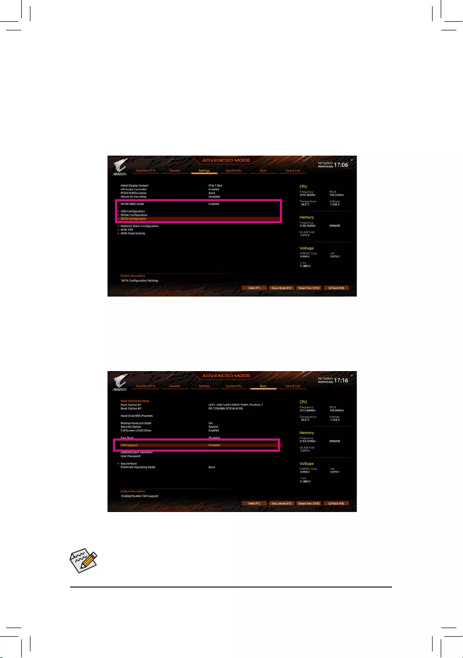
— 60 —
The BIOS Setup menus described in this section may differ from the exact settings for your motherboard.
The actual BIOS Setup menu options you will see shall depend on the motherboard you have and
the BIOS version.
Figure 1
B.ConguringSATAcontrollermodeinBIOSSetup
MakesuretoconguretheSATAcontrollermodecorrectlyinsystemBIOSSetup.
Step:
Turn on your computer and press <Delete> to enter BIOS Setup during the POST (Power-On Self-Test). Under
Settings\IO Ports, set SATAConguration\SATAMode to RAID (Figure 1). Then save the settings and
restartyourcomputer.(IfyouwanttouseNVMePCIeSSDstocongureRAID,makesuretosetNVMe RAID
mode to Enabled.)
C.UEFIRAIDConguration
Step 1:
In BIOS Setup, go to Boot and set CSM Support to Disabled (Figure 2). Save the changes and exit BIOS Setup.
Figure 2
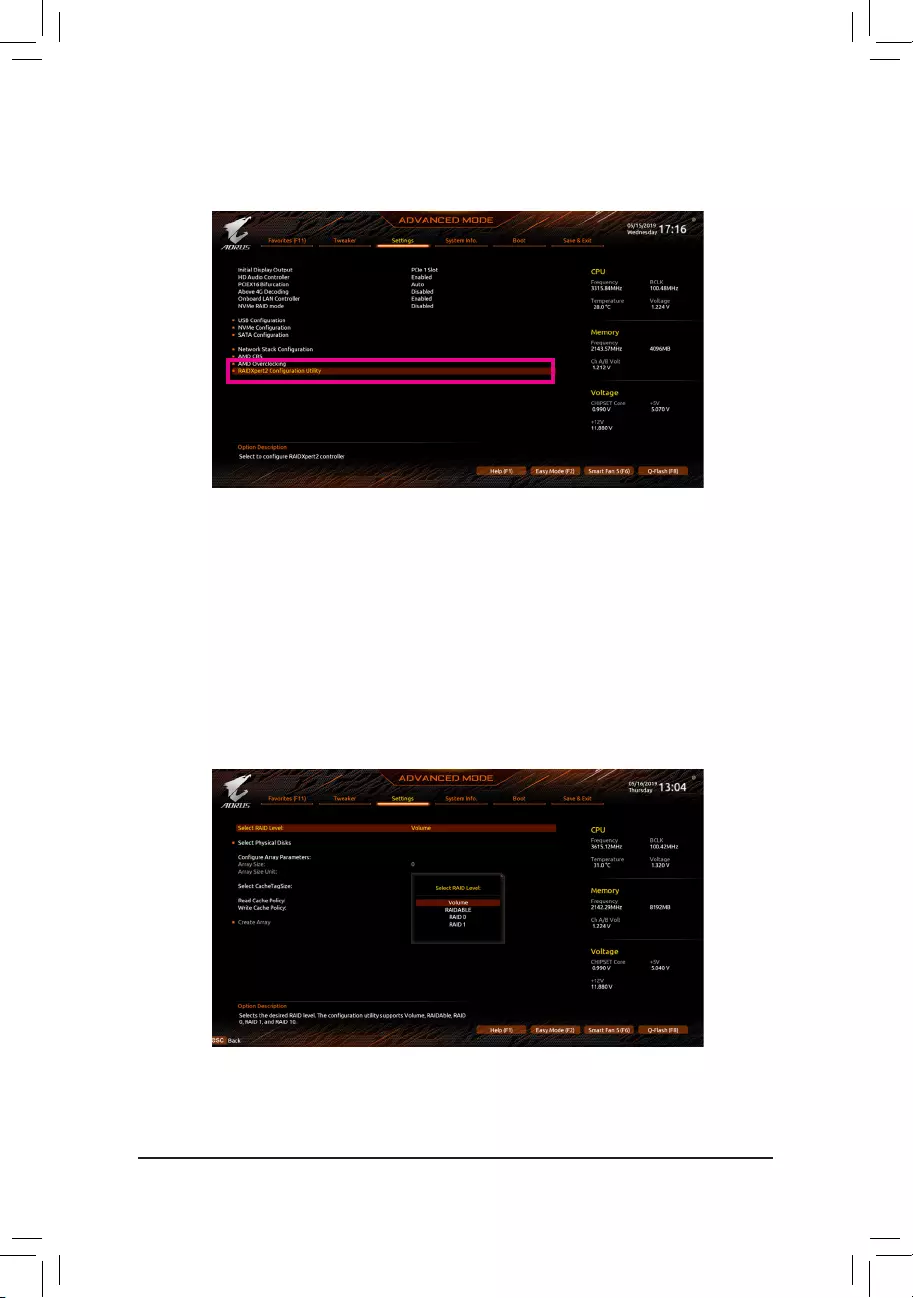
— 61 —
Step 2:
After the system reboot, enter BIOS Setup again. Then enter the Settings\RAIDXpert2CongurationUtility
sub-menu (Figure 3).
Figure 3
Step 3:
OntheRAIDXpert2CongurationUtilityscreen,press<Enter>onArray Management to enter the Create
Array screen. Then, select a RAID level (Figure 4). RAID levels supported include RAID 0, RAID 1, and RAID
10 (the selections available depend on the number of the hard drives being installed). Next, press <Enter> on
Select Physical Disks to enter the Select Physical Disks screen.
Figure 4
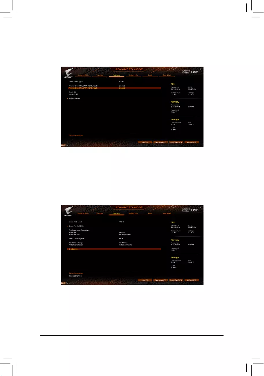
— 62 —
Step 4:
On the Select Physical Disks screen, select the hard drives to be included in the RAID array and set them to
Enabled. Next, use the down arrow key to move to Apply Changes and press <Enter> (Figure 5).Then return
to the previous screen and set the Array Size, Array Size Unit, Read Cache Policy and Write Cache Policy.
Figure 5
Step 5:
After setting the capacity, move to Create Array and press <Enter> to begin. (Figure 6)
Figure 6
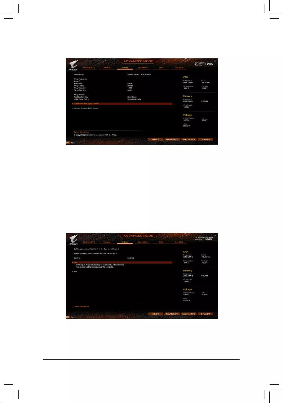
— 63 —
After completing, you’ll be brought back to the Array Management screen. Under Manage Array Properties
you can see the new RAID volume and information on RAID level, array name, array capacity, etc. (Figure 7)
Figure 7
Delete RAID Volume
To delete a RAID array, select the array to be deleted on the RAIDXpert2 CongurationUtility\Array
Management\Delete Array screen. Press <Enter> on Delete Array to enter the Delete screen. Then set
Conrmto Enabled and press <Enter> on Yes (Figure 8).
Figure 8
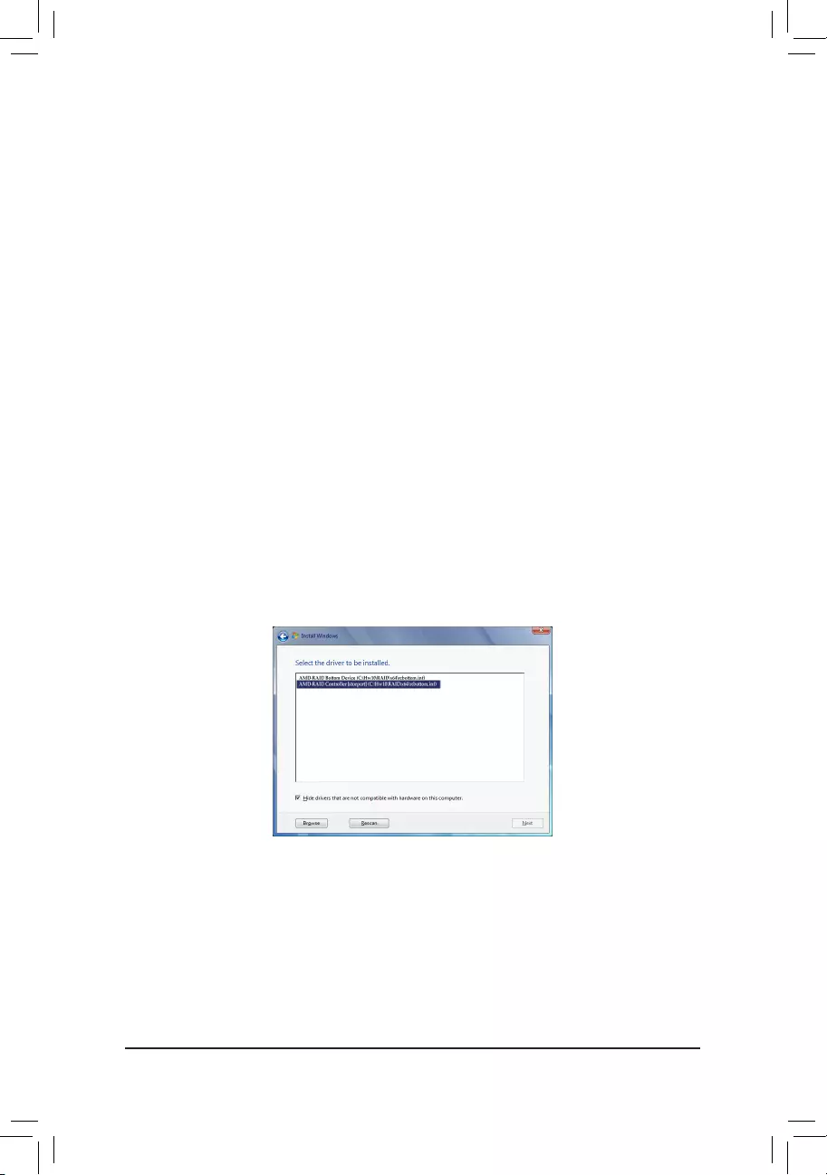
— 64 —
3-2 Installing the SATA RAID/AHCI Driver and Operating System
With the correct BIOS settings, you are ready to install the operating system.
A. Installing Windows
As some operating systems already include SATA RAID/AHCI driver, you do not need to install separate RAID/
AHCI driver during the Windows installation process. After the operating system is installed, we recommend
that you install all required drivers from the motherboard driver disk using «Xpress Install» to ensure system
performance and compatibility. If the operating system to be installed requires that you provide additional SATA
RAID/AHCI driver during the OS installation process, please refer to the steps below:
Step 1:
Copy the Hw10 folder under the \BootDrv folder in the driver disk to your USB thumb drive.
Step 2:
Boot from the Windows setup disk and perform standard OS installation steps. When the screen requesting you
to load the driver appears, select Browse.
Step 3:
Insert the USB thumb drive and then browse to the location of the driver. The location of the driver is as follows:
Windows 64-bit: \Hw10\RAID\x64
Step 4:
When a screen as shown in Figure 1 appears, select AMD-RAID Bottom DevicerstandclickNext to load the
driver. Then select AMD-RAID Controller and click Next to load the driver. Finally, continue the OS installation.
Figure 1
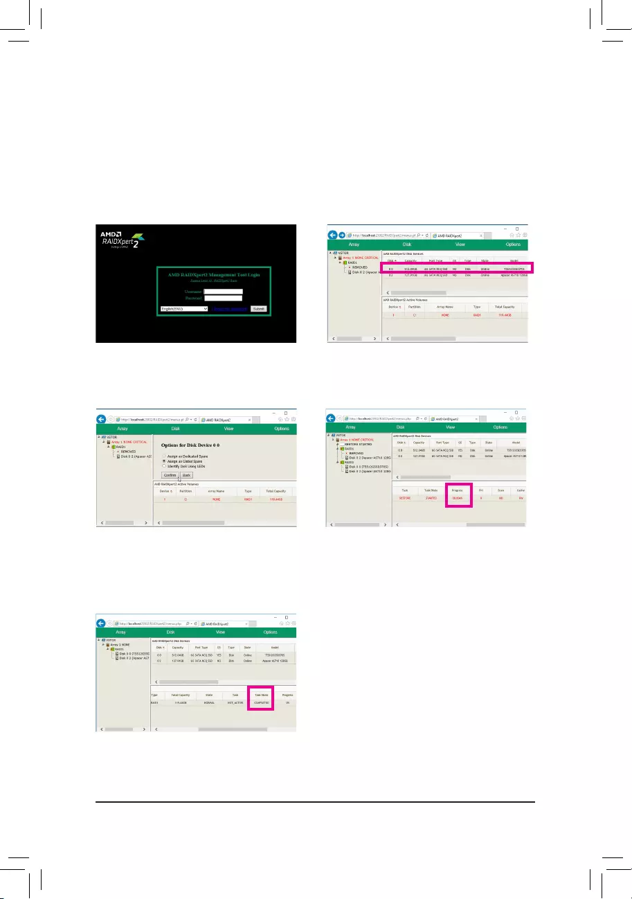
— 65 —
B. Rebuilding an Array
Rebuilding is the process of restoring data to a hard drive from other drives in the array. Rebuilding applies
only to fault-tolerant arrays such as RAID 1 and RAID 10 arrays. To replace the old drive, make sure to use a
new drive of equal or greater capacity. The procedures below assume a new drive is added to replace a failed
drive to rebuild a RAID 1 array.
While in the operating system, make sure the Chipset and RAID drivers have been installed from the motherboard
driver disk. Then double-click the RAIDXpert2 icon on the desktop to launch the RAID utility.
Step 1:
Enter the login ID and password (default: «admin»),
and then click Submit to launch AMD RAIDXpert2.
Step 2:
In the Disk Devices section, left-click your mouse
twice on the newly-added hard drive.
Step 3:
On the next screen, select Assign as Global Spare
and click Conrm.
Step 4:
During the rebuild process, you can select the array
that is being built (displayed in red) in the Active
Volumes section to check the current progress.
Step 5:
Then rebuild is complete when the Task State
column shows «COMPLETED.»

— 66 —
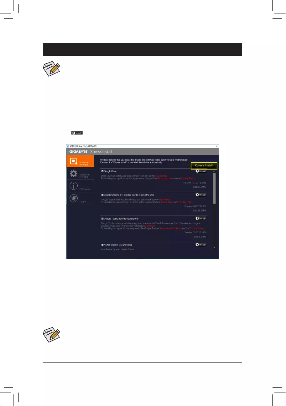
— 67 —
4-1 Drivers & Software
Chapter 4 Drivers Installation
•Beforeinstallingthedrivers,rstinstalltheoperatingsystem.
•After installing the operating system, insert the motherboard driver disk into your optical drive.
Click on the message «Tap to choose what happens with this disc» on the top-right corner of
the screen and select «Run Run.exe.» (Or go to My Computer, double—click the optical drive
and execute the Run.exe program.)
•Please ignore the popup dialog box(es) (e.g. the Found New Hardware Wizard) displayed
when «Xpress Install» is installing the drivers. Failure to do so may affect the driver installation.
•Some device drivers will restart your system automatically during the driver installation. After the
system restart, «Xpress Install» will continue to install other drivers.
«Xpress Install» will automatically scan your system and then list all of the drivers that are recommended to
install. You can click the Xpress Install button and «Xpress Install» will install all of the selected drivers. Or
click the arrow icon to individually install the drivers you need.
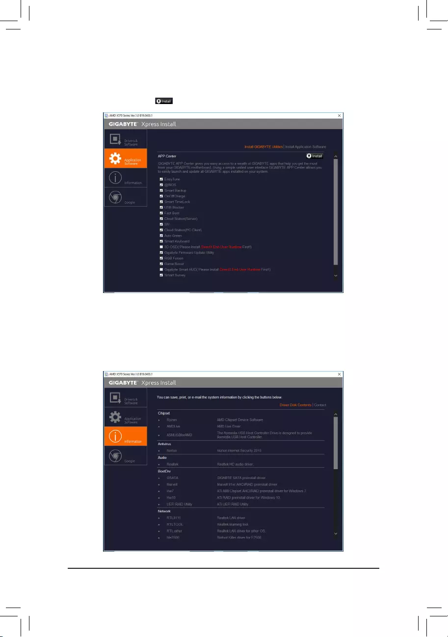
— 68 —
4-3 Information
This page provides detailed information on the drivers on the driver disk. The Contact page provides
contact information of the GIGABYTE Taiwan headquarter. You can click the URL on this page to link to the
GIGABYTEwebsitetocheckmoreinformationontheGIGABYTEheadquarterorworldwidebranchofces.
4-2 Application Software
This page displays the apps that GIGABYTE develops and some free software. You can select the apps
you want and click the Install icon to begin the installation.

— 69 —
Chapter 5 Unique Features
BecauseBIOSashingispotentiallyrisky,pleasedoitwithcaution.InadequateBIOSashingmay
result in system malfunction.
5-1-1 Updating the BIOS with the Q-Flash Utility
A. Before You Begin
1. FromGIGABYTE’swebsite,downloadthelatestcompressedBIOSupdatelethatmatchesyourmotherboard
model.
2. ExtracttheleandsavethenewBIOSle(e.g.X570AORUSMASTER.F1)toyourUSBashdrive,orhard
drive.Note:TheUSBashdriveorharddrivemustuseFAT32/16/12lesystem.
3. Restart the system. During the POST, press the <End> key to enter Q-Flash. Note: You can access Q-Flash
by either pressing the <End> key during the POST or click the Q-Flash icon (or press the <F8> key) in BIOS
Setup.However,iftheBIOSupdateleissavedtoaharddriveinRAID/AHCImodeoraharddriveattached
to an independent SATA controller, use the <End> key during the POST to access Q-Flash.
5-1 BIOS Update Utilities
GIGABYTE motherboards provide two unique BIOS update tools, Q-Flash™ and @BIOS™. GIGABYTE Q-Flash
and @BIOS are easy-to-use and allow you to update the BIOS without the need to enter MS-DOS mode.
Additionally, this motherboard features the DualBIOS™ design and supports Q-Flash Plus, providing multiple
protection for the safety and stability of your computer.
What is DualBIOS™?
Motherboards that support DualBIOS have two BIOS onboard, a main BIOS and a backup BIOS. Normally, the
system works on the main BIOS. However, if the main BIOS is corrupted or damaged, the backup BIOS will
take over on the next system boot to ensure normal system operation.
What is Q-Flash Plus?
Q-Flash Plus allows you to update the BIOS when your system is off (S5 shutdown state). Save the latest BIOS
onaUSBthumbdriveandplugitintothededicatedport,andthenyoucannowashtheBIOSautomatically
by simply pressing the Q-Flash Plus button.
What is Q-Flash™?
With Q-Flash you can update the system BIOS without having to enter operating systems like MS-DOS or
Windowrst.EmbeddedintheBIOS,theQ-Flashtoolfreesyoufromthehasslesofgoingthroughcomplicated
BIOSashingprocess.
What is @BIOS™?
@BIOS allows you to update the system BIOS while in the Windows environment. @BIOS will download the
latestBIOSlefromthenearest@BIOSserversiteandupdatetheBIOS.
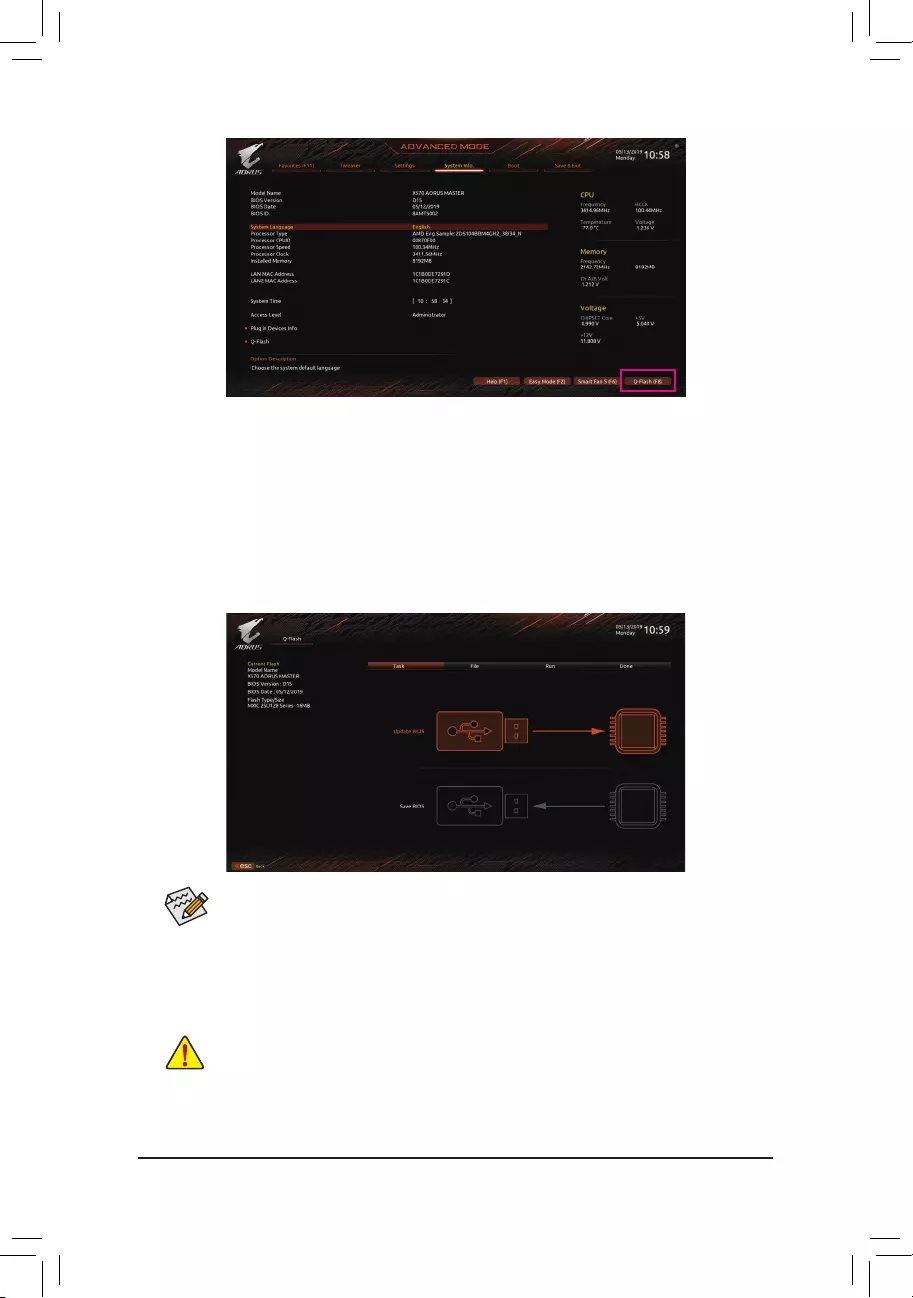
— 70 —
B. Updating the BIOS
In the main menu of Q-Flash, use the keyboard or mouse to select an item to execute. When updating the BIOS,
choosethelocationwheretheBIOSleissaved.Thefollowingprocedureassumesthatyouhavesavedthe
BIOSletoaUSBashdrive.
Step 1:
1. InserttheUSBashdrivecontainingtheBIOSleintothecomputer.InthemainscreenofQ-Flash,select
Update BIOS.
•The Save BIOSoptionallowsyoutosavethecurrentBIOSle.
•Q-FlashonlysupportsUSBashdriveorharddrivesusingFAT32/16/12lesystem.
•IftheBIOSupdateleissavedtoaharddriveinRAID/AHCImodeoraharddriveattached
to an independent SATA controller, use the <End> key during the POST to access Q-Flash.
2. SelecttheBIOSupdatele.
MakesuretheBIOSupdatelematchesyourmotherboardmodel.
Click Q-Flash (F8) or select the Q-Flash item on the System Info menu to access Q-Flash.
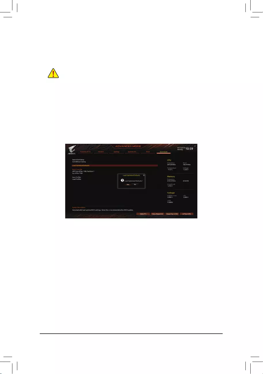
— 71 —
Step 2:
ThescreenwillshowthattheBIOSleisbeingreadfromyourUSBashdrive.PleaseselectFast or Intact to
begin the BIOS update. The screen will then display the update process.
Step 3:
The system will restart after the update process is complete.
•Do not turn off or restart the system when the system is reading/updating the BIOS.
•DonotremovetheUSBashdriveorharddrivewhenthesystemisupdatingtheBIOS.
Step 4:
During the POST, press <Delete> to enter BIOS Setup. Select Load Optimized Defaults on the Save & Exit
screen and press <Enter> to load BIOS defaults. System will re-detect all peripheral devices after a BIOS update,
so we recommend that you reload BIOS defaults.
Step 5:
Select Save & Exit Setup and press <Enter>. And then select Yes to save settings to CMOS and exit BIOS
Setup. The procedure is complete after the system restarts.
Select Yes to load BIOS defaults
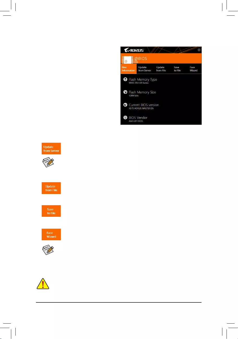
— 72 —
5-1-2 Updating the BIOS with the @BIOS Utility
A. Before You Begin
1. In Windows, close all applications and TSR
(Terminate and Stay Resident) programs. This
helps prevent unexpected failures when performing
a BIOS update.
2. If the BIOS is being updated via the Internet, ensure
the Internet connection is stable and do NOT
interrupt the Internet connection (for example, avoid
a power loss or switching off the Internet). Failure to
do so may result in a corrupted BIOS or a system
that is unable to start.
3. GIGABYTE product warranty does not cover any
BIOS damage or system failure resulting from an
inadequateBIOSashing.
B. Using @BIOS
•MakesurethattheBIOSletobeashedmatchesyourmotherboardmodel.UpdatingtheBIOS
withanincorrectBIOSlecouldcauseyoursystemnottoboot.
•Do not turn off the system or remove the power during the BIOS update process, or the BIOS may
corrupt and the system may not boot.
IftheBIOSupdateleforyourmotherboardisnotpresentonthe@BIOSserversite,please
manuallydownloadtheBIOSupdatelefromGIGABYTE’swebsiteandfollowtheinstructionsin
«Update the BIOS without Using the Internet Update Function» below.
Supported image formats include jpg, bmp, and gif.
C. After Updating the BIOS
Restart your system after updating the BIOS.
1. Update the BIOS Using the Internet Update Function:
Click Update from Server, select the @BIOS server site closest to your location and
thendownloadtheBIOSlethatmatchesyourmotherboardmodel.Followtheon-screen
instructions to complete.
2. Update the BIOS without Using the Internet Update Function:
Click Update from File,thenselectthelocationwhereyousavetheBIOSupdateleobtained
from the Internet or through other source. Follow the on-screen instructions to complete.
3. Save the Current BIOS File:
Click Save to FiletosavethecurrentBIOSle.
4. Change the Boot-up Logo:
Click Upload new image in Face-Wizard and you will be able to change the boot-up logo
with your own picture, creating a personalized boot-up screen. Click Backup current image
to save the current boot-up logo.
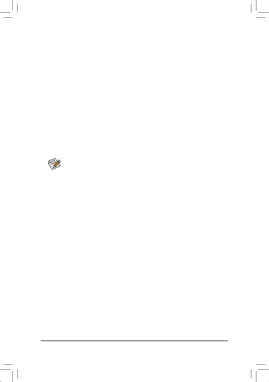
— 73 —
5-1-3 Using Q-Flash Plus
A. Before you use Q-Flash Plus, follow the steps below in sequence:
1. From GIGABYTE’s website, download the latest compressed BIOS update le that matches your motherboard
model.
2. Uncompress the downloaded BIOS le, save it to your USB ash drive, and rename it to GIGABYTE.bin.
Note: The USB ash drive must use the FAT32/16 le system.
3. Insert the USB ash drive into the white USB port on the back panel.
4. Connect the power cables to the 12V power connector (connect either one if there are two) and main power
connector.
B. Using Q-Flash Plus
Press the Q-Flash Plus button and the system will automatically search and match the BIOS le in the USB
ash drive on the white USB port. The QFLED and the Q-Flash Plus button on the rear panel will ash during
the BIOS matching and ashing process. Wait for 2-3 minutes and the LED will stop ashing when the BIOS
ashing is complete.
•Before using the Q-Flash Plus function, make sure that your system is off (S5 shutdown state).
•If your motherboard has a BIOS switch and a SB switch, reset them to their default settings.
(Default setting for the BIOS switch: Boot from the main BIOS; default setting for the SB switch:
Dual BIOS)
•After the main BIOS is ashed, the system will reboot automatically and then DualBIOS™ will
continue to update the backup BIOS. After completion, the system will reboot again and boot
from the main BIOS.
•Q-Flash Plus will update the main BIOS only if run without the CPU installed. The system will
shut down upon completion.
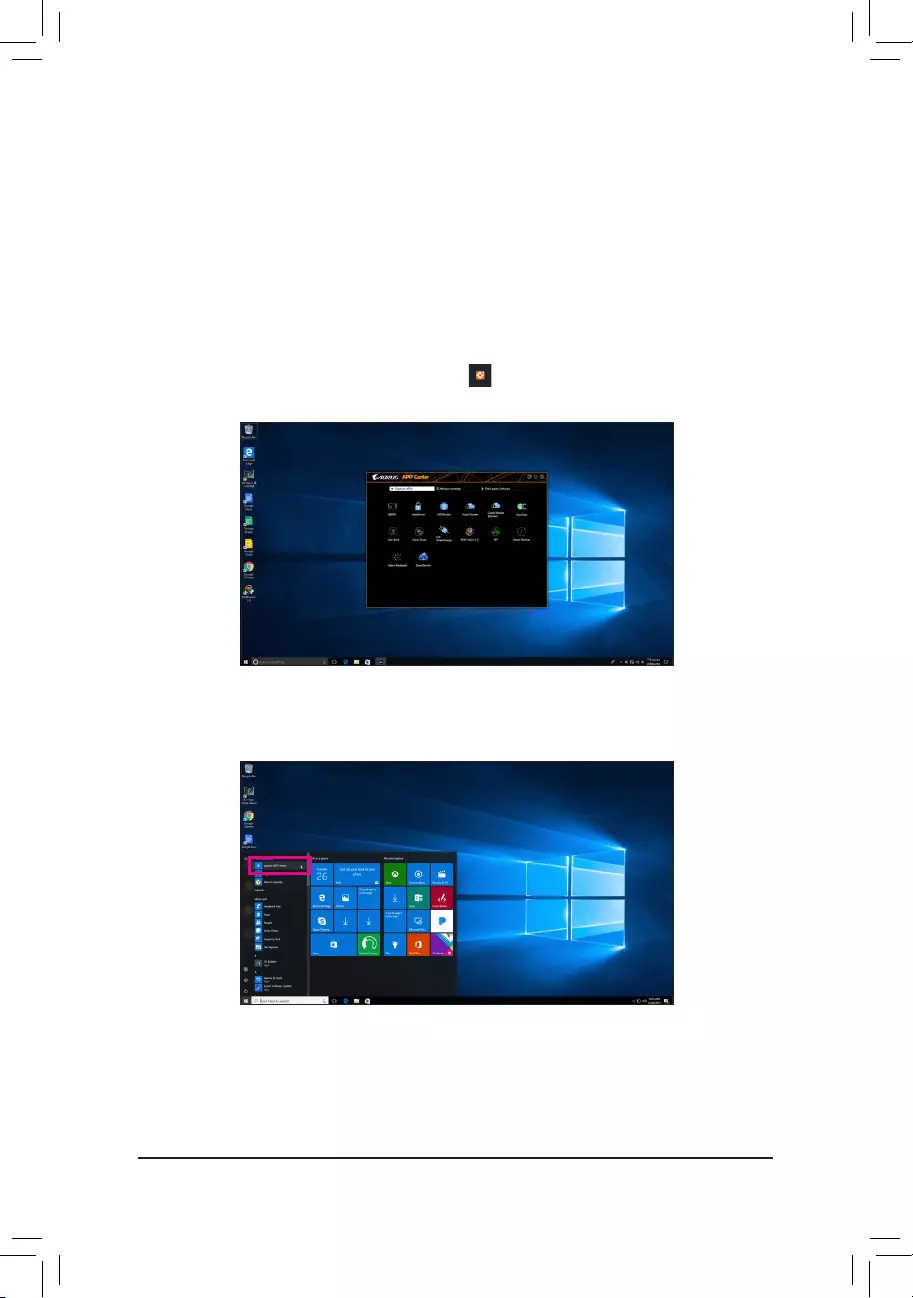
— 74 —
5-2 APP Center
GIGABYTE App Center gives you easy access to a wealth of GIGABYTE apps that help you get the most from
your GIGABYTE motherboard (Note).Usingasimple,unieduserinterface,GIGABYTEAppCenterallowsyou
to easily launch all GIGABYTE apps installed on your system, check related updates online, and download the
apps, drivers, and BIOS.
Running the APP Center
Insert the motherboard driver disk. On the Autorun screen, go to Application Software\Install GIGABYTE
Utilities to install GIGABYTE App Center and the selected apps. Restart your computer after the installation
is complete. In Desktop mode, click the App Center icon inthenoticationareatolaunchtheAppCenter
utility (Figure 1). On the main menu, you can select an app to run or click LiveUpdate to update an app online.
If the App Center is closed, you can restart it by clicking Launch App Center on the Start menu (Figure 2).
Figure 2
Figure 1
(Note) Available applications in APP Center may differ by motherboard model. Supported functions of each
applicationmayalsovarydependingonmotherboardspecications.
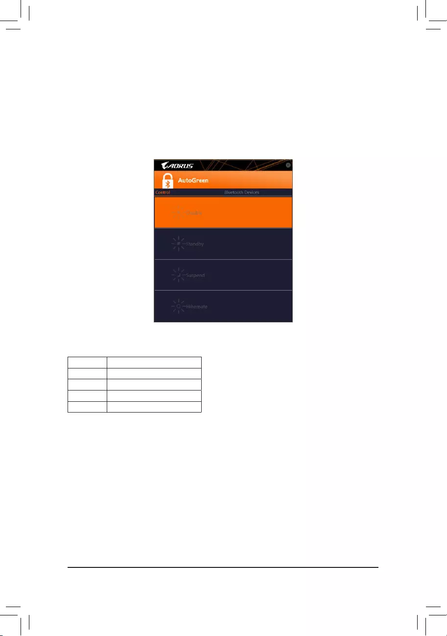
— 75 —
Control Tab:
The Control tab allows you to select a system power saving mode.
Button Description
Disable Disables this function
Standby Enters Power on Suspend mode
Suspend Enters Suspend to RAM mode
Hibernate Enters Suspend to Disk mode
(Note) Once your smart phone/tablet device has been paired with your AutoGreen-enabled computer, you’ll
not be able to use it to connect to other Bluetooth device(s).
Bluetooth Devices Tab:
The Bluetooth tab allows you to pair your smart phone/tablet device with the Bluetooth receiver on your computer.
Press Refresh to let AutoGreen search for the Bluetooth devices around you. A message will appear on both
your computer and smart phone/tablet device prompting you to compare the passcodes on the two devices.
Conrmtocompletethepairingprocess.
5-2-1 AutoGreen
AutoGreen (Note) is an easy-to-use tool that provides users with simple options to enable system power savings
via a Bluetooth-enabled smart phone/tablet device. When the device is out of the range of the computer’s
Bluetoothreceiver,thesystemwillenterthespeciedpowersavingmode.Beforeusingthisapp,youneedto
turn on Bluetooth on both your computer and smart phone/tablet device.
The AutoGreen Interface
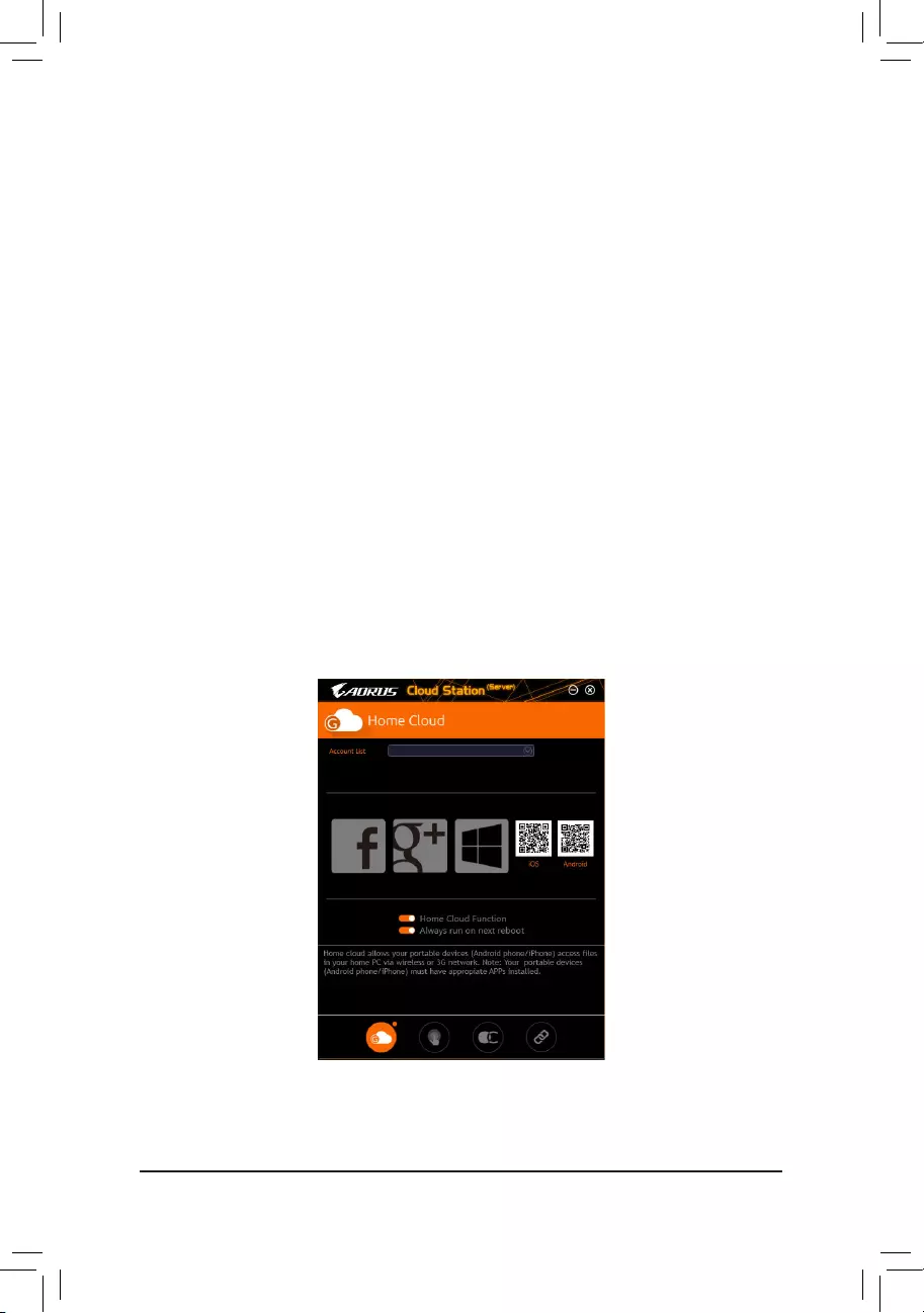
— 76 —
5-2-2 Cloud Station
GIGABYTE Cloud Station (Server) is composed of HomeCloud, GIGABYTE Remote, Remote OC, and HotSpot,
which allow your smart phone, tablet device, and remote computer to communicate, share resources, and control
thehostcomputerviawirelessconnection. Cloud Station allows your computertoshareleswithanother
computer that has Cloud Station (Server) installed.
Before You Begin:
•To use HomeCloud, GIGABYTE Remote, and Remote OC, you must install GIGABYTE Cloud Station on
your smart phone/tablet device. (For Android systems, please download the app from Google Play; for iOS
systems, please download it from App Store.) (Note 1)
•ToshareHomeCloudlesbetweencomputers,youneedtoinstallCloudStation(Server)onthehostcomputer
and Cloud Station on the remote computer.
•Your smart phone/tablet device must have Android 4.0/iOS 6.0 or above version.
•ThersttimeyouuseHomeCloud,GIGABYTERemote,andRemoteOC,youmustsigninwithyourGoogle/
Facebook/Windows Live account. Be sure to use the same account to sign in on your smart phone/tablet
device and computers.
HomeCloud
HomeCloudallowsyoutoupload/download/backuples (Note 2) from your smart phone/tablet device/computer
to the host computer.
The HomeCloud Interface
Cloud Station (Server):
(Note 1) You can use your smart phone/tablet device to scan the QR code on the HomeCloud UI to link to the
download page of the GIGABYTE Cloud Station on App Store or Google Play.
(Note2) ForiOSsystems,theletypesarelimitedtoimage/videoles.
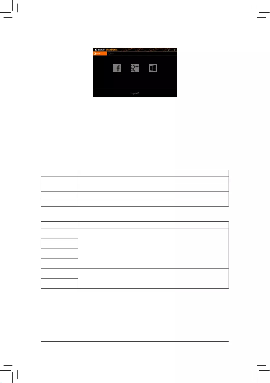
— 77 —
On the Host Computer:
Option Function
Account List Displays currently signed in account(s).
Remove Remove the selected account.
Share Folder Displays the shared folder directory of the currently signed in account.
Open Folder Access the shared folder of the currently signed in account.
On the Smart Phone/Tablet Device/Remote Computer:
Option Function
All Picture Files FileUpload:Taponthefolder,browseandselectthelesinside.Taponthemenuicon
and select Upload selected Filestouploadthelestoyourcomputer.
File Download: Tap on the folder and then tap on the menu icon, select Download
Files.Youcanbrowsethelesandselectthelesthatyouwanttodownloadtoyour
smart phone/tablet device.
All Music Files
All Video Files
All Files
User Contacts Tap on the folder and then tap on the menu icon to use the options including Backup
to remote, Restore From remote, View Remote Contact, and Reselect Computers.
Call Log
Using HomeCloud
Step 1:
Launch HomeCloud on the host computer (installed with Cloud Station (Server)), sign in with your Google/
Facebook/Windows Live account or select the account on the Account List. Then enable HomeCloud Function.
To automatically enable this function after system reboot, enable Always run on next reboot.
Step 2:
Run Cloud Station on your smart phone/tablet device/remote computer, sign in with the same account you use
for HomeCloud on your host computer. Tap on HomeCloud to perform the following functions:
Cloud Station:
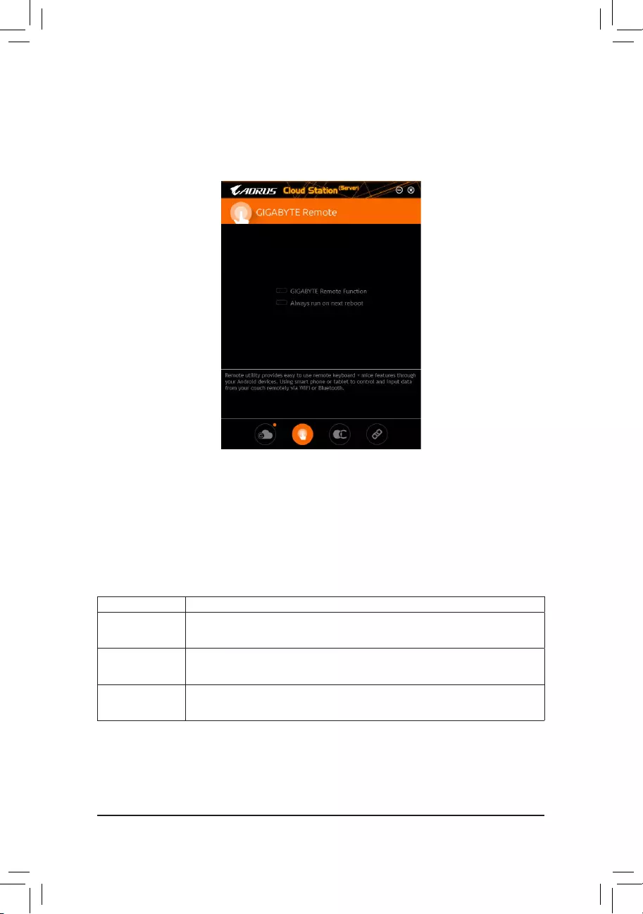
— 78 —
GIGABYTE Remote
GIGABYTE Remote allows you to use your smart phone/tablet device to remotely control the mouse/keyboard/
Windows Media Player on your computer.
The GIGABYTE Remote Interface
Using GIGABYTE Remote
Step 1:
On the host computer, launch GIGABYTE Remote and enable GIGABYTE Remote Function. To automatically
enable this function after system reboot, enable Always run on next reboot.
Step 2:
Run GIGABYTE Cloud Station on your smart phone/tablet device, sign in with the same account you use for
HomeCloud on your computer. Tap on Remote Control to perform the following remote controls:
On the Smart Phone/Tablet Device:
Option Function
Mouse Remotely perform mouse functionalities including dragging, right/left-clicking, and
holding the mouse left button.
Keyboard Remotely control your keyboard such as text input (tap on Real-Time Mode to type
texts) or deletion.
Media RemotelycongureandcontrolthecurrentlyrunningWindowsMediaPlayerapplication
on your computer.
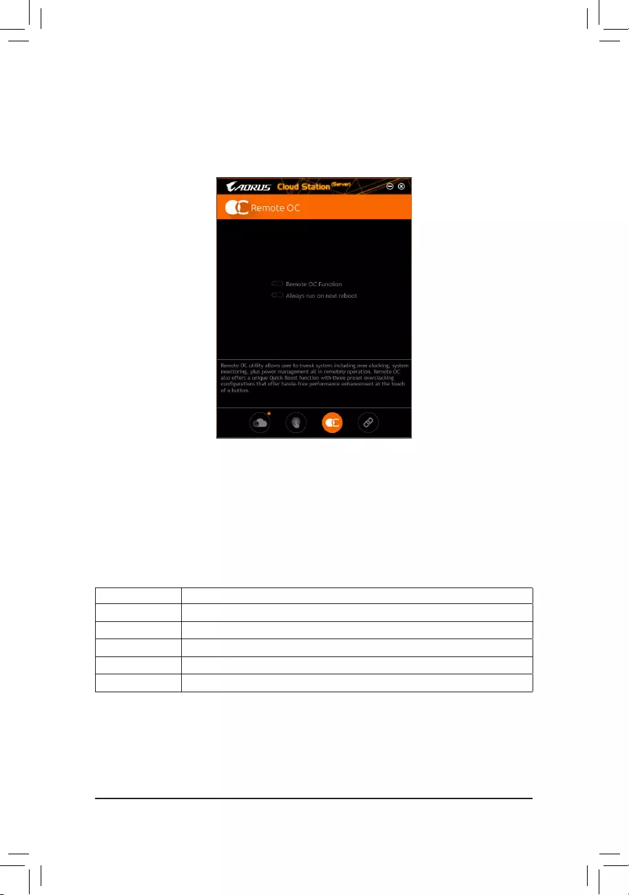
— 79 —
Remote OC
Remote OC provides you with remote control options including overclocking and system tweaking, system
monitoring plus the ability to also remotely power down/reset the PC when needed.
The Remote OC Interface
Using Remote OC
Step 1:
On the host computer, launch Remote OC and enable Remote OC Function. To automatically enable this
function after system reboot, enable Always run on next reboot.
Step 2:
Run GIGABYTE Cloud Station on your smart phone/tablet device, sign in with the same account you use for
HomeCloud on your computer. Tap on Remote OC to perform the following functions:
On the Smart Phone/Tablet Device:
Option Function
Tuner Allows you to change CPU/memory frequency and voltage settings.
INFO Displays the system information, including the CPU, motherboard, and memory.
HW MONIT Allows you to monitor system temperatures, voltages, and fan speeds.
QUICK BOOST Providesyouwiththreepresetoverclockingcongurations.
CONTROL Allows you to remotely reboot or shut down your computer.

— 80 —
HotSpot
HotSpot turns your computer into a virtual wireless access point and allows you to share your connection with
your other wireless devices. Make sure your computer has been connected to a network and Wi-Fi is enabled.
The HotSpot Interface
Using HotSpot:
Conguringyourhostcomputer:
The options are as follows. Make sure to click Start to complete.
•Make this network connection available for sharing:
Select a currently running network connection you want to share.
•Available HotSpot device:
Select a network virtual adapter. If there are more than one Wi-Fi card on your computer, you need to select
the one you want to use from the list.
•SSID:
The hotspot SSID name. You can keep the default name or create your own one.
•HotSpot Password(must have at least 8 characters):
The password is required when other wireless devices want to access the Internet through the virtual wireless
access point. You can keep the default name or create your own one. The password must have at least 8
characters and cannot be empty.
Sharing your connection with other wireless devices:
FirstmakesureWi-Fiisenabledonthewirelessdevices.Thenbrowsetothenetworkcongurationscreen,
search for available Wi-Fi networks, and tap the name of your virtual wireless access point, enter the password,
andconrm.
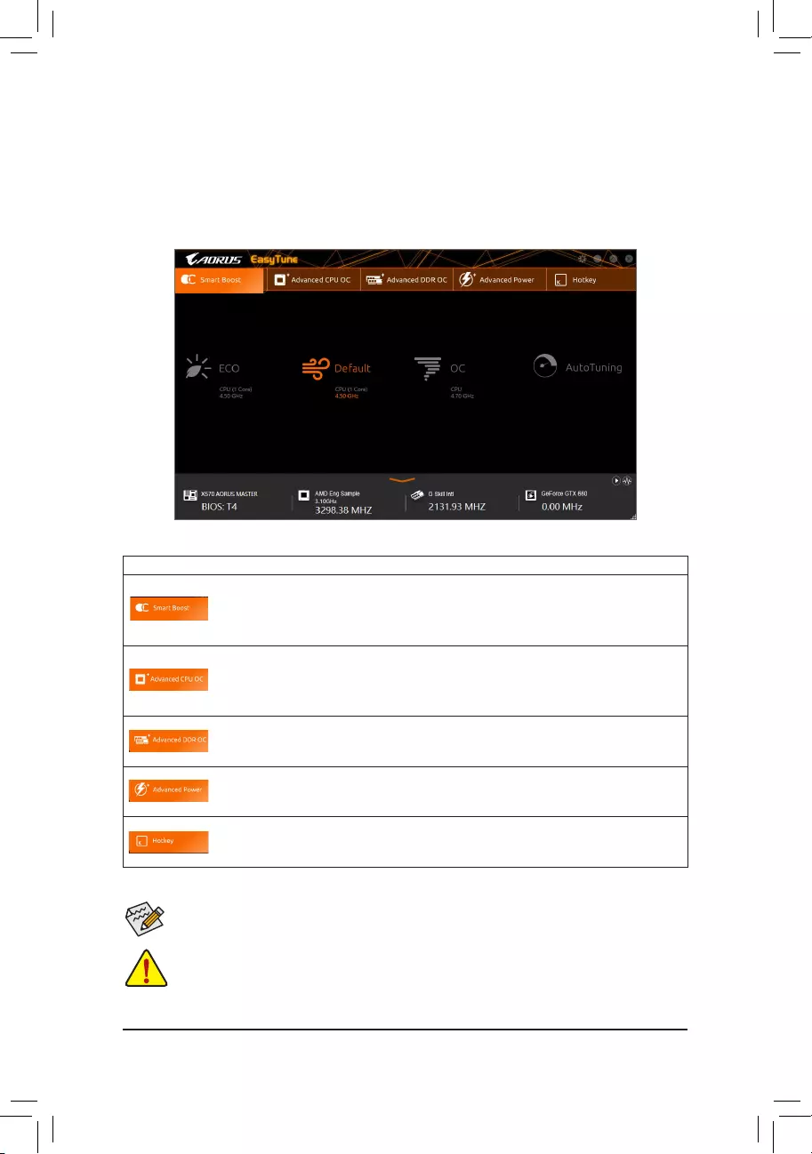
— 81 —
5-2-3 EasyTune
GIGABYTE’sEasyTuneisasimpleandeasy-to-useinterfacethatallowsuserstone-tunetheirsystemsettings
or do overclock/overvoltage in Windows environment.
The EasyTune Interface
Tabs Information
Tab Description
The Smart Boost tab provides you with different levels of CPU frequency to choose to
achieve desired system performance. After making changes, be sure to restart your system
for these changes to take effect.
The Advanced CPU OC tab allows you to set CPU base clock, frequency, and voltages,
andintegratedgraphicsfrequency.Youcansavethecurrentsettingstoaprole.Youcan
createupto2proles.
The Advanced DDR OC tab allows you to set the memory clock.
The Advanced Power tab allows you to adjust voltages.
The HotKeytaballowsyoutosethotkeysforyourproles.
Incorrectly doing overclock/overvoltage may result in damage to the hardware components such
as CPU, chipset, and memory and reduce the useful life of these components. Before you do the
overclock/overvoltage, make sure that you fully know each function of EasyTune, or system instability
or other unexpected results may occur.
Available functions in EasyTune may vary by motherboard model and CPU. Grayed-out area(s)
indicatesthattheitemisnotcongurableorthefunctionisnotsupported.
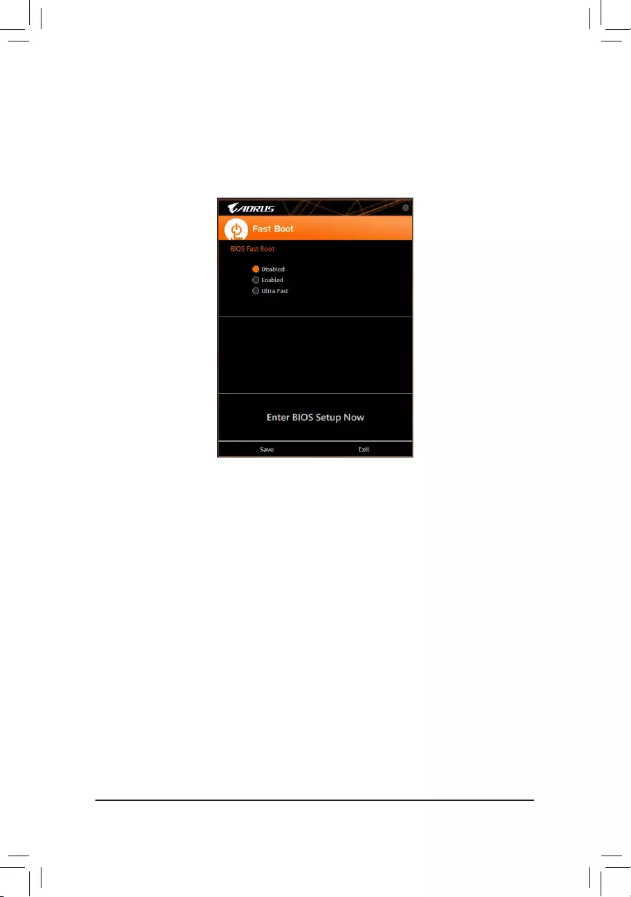
— 82 —
5-2-4 Fast Boot
Through the simple GIGABYTE Fast Boot interface, you can enable or change the Fast Boot setting right
in the operating system.
The Fast Boot Interface
Using Fast Boot
•BIOS Fast Boot:
This option is the same as the Fast Boot option (Note) in BIOS Setup. It allows you to enable or disable the
fast boot function to shorten OS boot time.
Afteryoucongurethesettings,clickSave to save and click Exit. The settings will take effect on next boot. If
you click the Enter BIOS Setup Now button, the system will restart and enter BIOS Setup immediately.
(Note) For more details about this function, refer to Chapter 2, «BIOS Setup.»
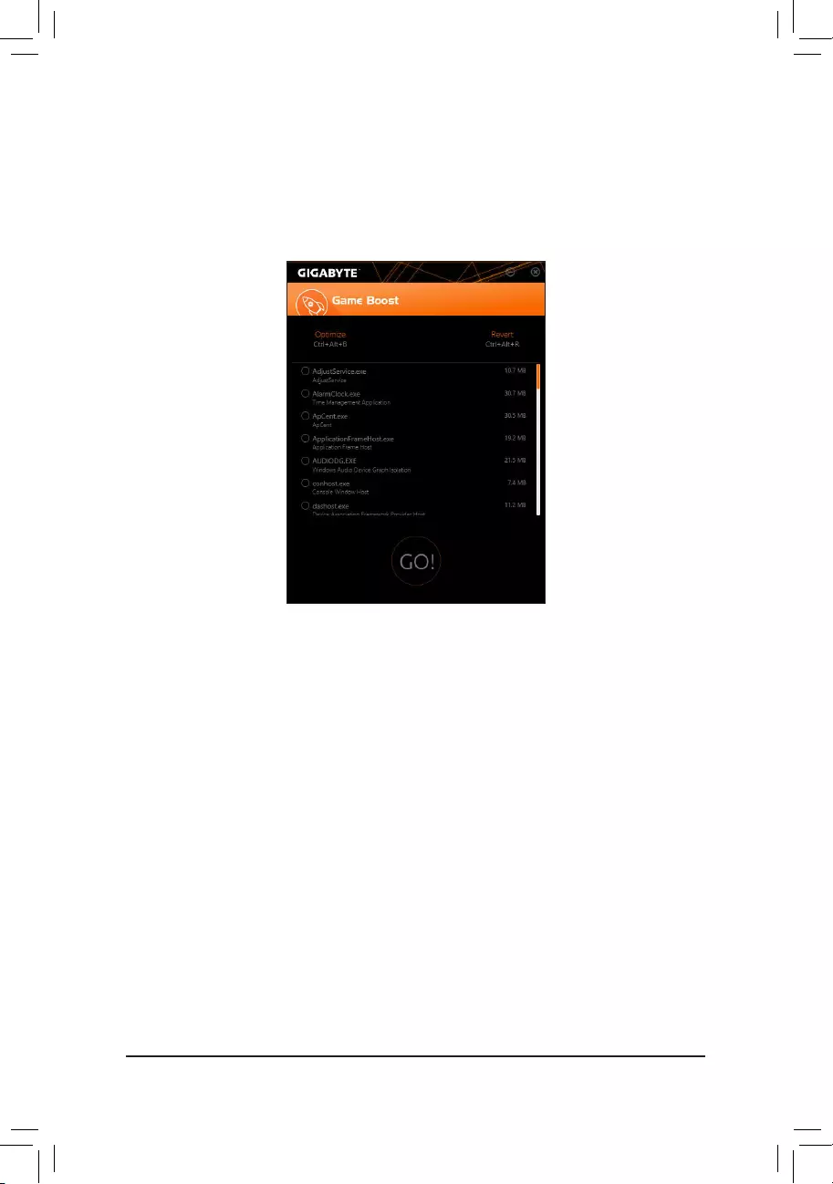
— 83 —
5-2-5 Game Boost
Thisappallowsyoutoexiblymanageyourapplicationstooptimizeyourgamingperformancebyfreeingup
system resources and memory usage.
The Game Boost Interface
Using Game Boost
Select the application you want to suspend and then click Go to optimize your system for gaming. To revert
the computer back to the state it was before, click Revert. In addition, two hotkeys are provided as follows:
•Optimize(Ctrl+Alt+B): Automatically optimizes your gaming platform and gaming performance.
•Revert(Ctrl+Alt+R): Restores your computer back to the state before the gaming begins.
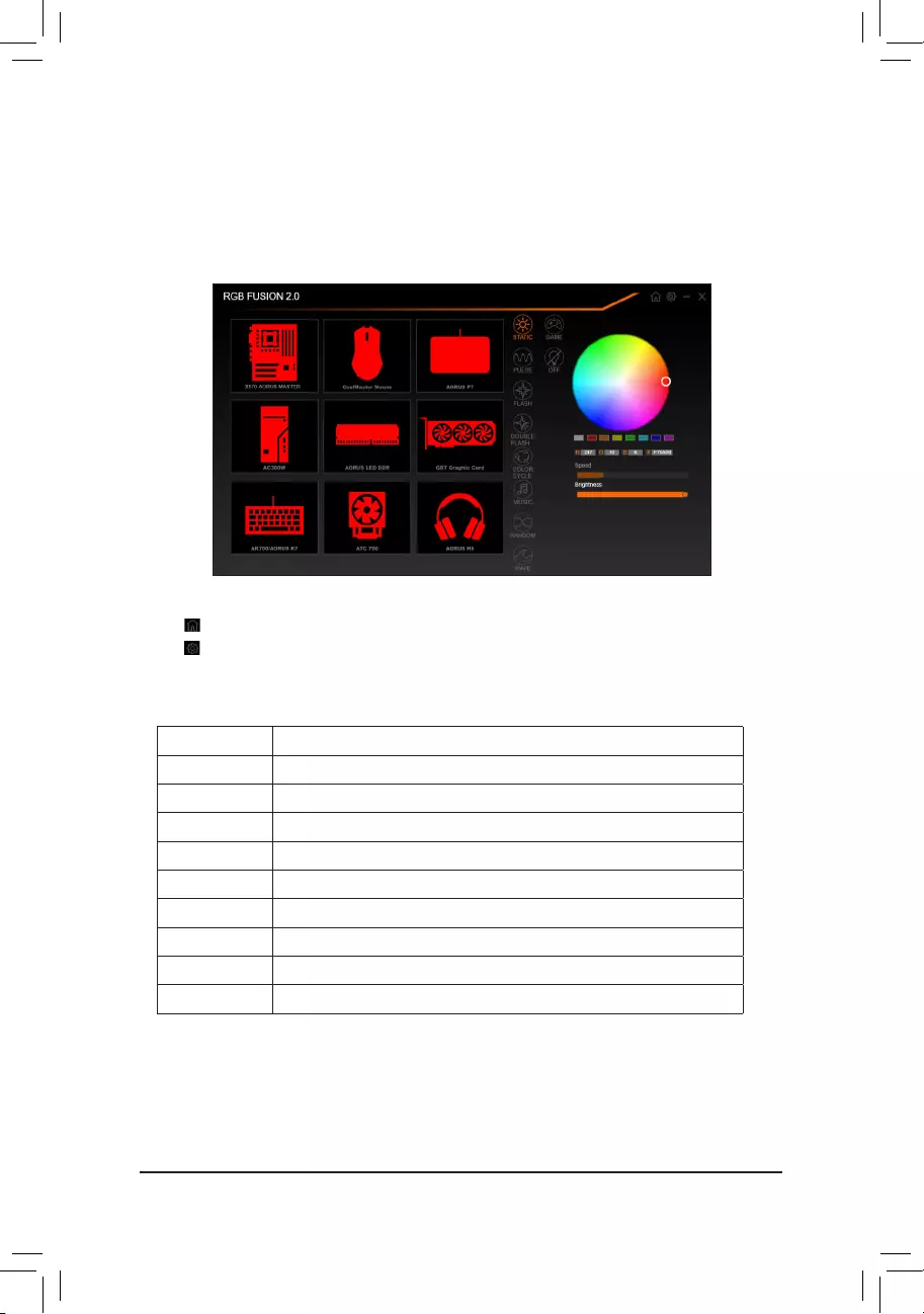
— 84 —
5-2-6 RGB Fusion
This application allows you to enable or specify the lighting mode of the select device (Note 1) while in the
Windows environment.
The RGB Fusion Interface
Using RGB Fusion
•The icon on the top right corner: Allows you to return to the main menu.
The icon on the top right corner: Allows your computer to connect to the GIGABYTE RGB Fusion app
installed on your handheld devices. (Note 2)
•Click the icon of the desired device and select the LED color/ lighting behaviour on the right section of the screen.
Static All LEDs emit a single color.
Pulse All LEDs simultaneously fade in and fade out.
Flash AllLEDssimultaneouslyashonandoff.
Double Flash AllLEDsashinaninterlacedpattern.
Color Cycle All LEDs simultaneously cycle through a full spectrum of colors.
Music All LEDs are synchronized with your music.
Random SingleLEDregionsashrandomly.
Wave A full color spectrum cascades throughout the LED.
Game All LEDs are synchronized with your game.
Off Turn off all LEDs.
(Note 1) RGB Fusion will automatically search for the devices that have LED lighting feature and display them
on the list.
(Note 2) Please download the RGB Fusion app from App Store or Google Play.
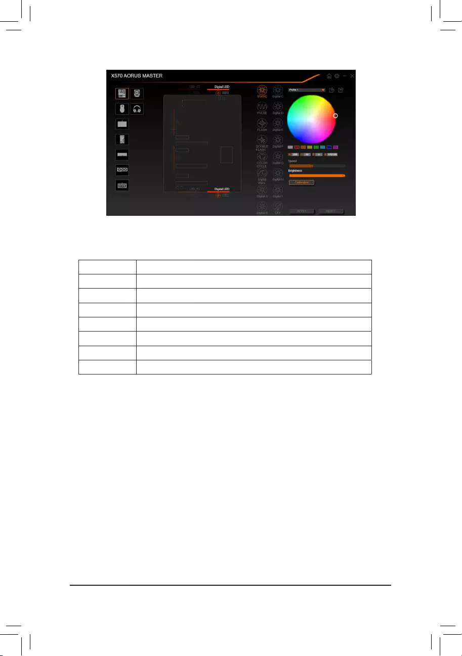
— 85 —
•Options for controlling the LEDs on the motherboard and digital LED strip. Click the motherboard icon for
further settings. (Note)
Select your desired area and select the LED color/ lighting behaviour on the right section of the screen.
Static The selected region LEDs emit a single color.
Pulse The selected region LEDs simultaneously fade in and fade out.
Flash TheselectedregionLEDssimultaneouslyashonandoff.
Double Flash AllLEDsashinaninterlacedpattern.
Color Cycle All LEDs simultaneously cycle through a full spectrum of colors.
Digital Wave A full color spectrum cascades throughout the armor LED.
DigitalA~IMode Provides multiple digital lighting mode throughout the armor LED and LED strip.
Off Disable the selected region LEDs.
(Note) Regions/Modes/Colors available may vary by motherboard.
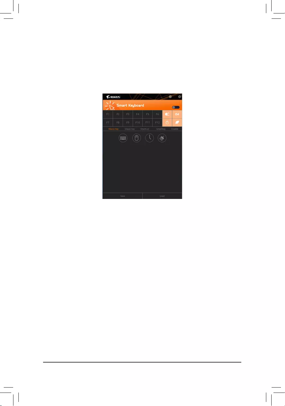
— 86 —
5-2-7 Smart Keyboard
GIGABYTE Smart Keyboard allows you to set your own hotkeys using the F1 through F12 keys. You can use the
customizedhotkeystochangethemousesensitivity,replaceawordorpassword,openaleoranapplication,
all of which helps to make the most out of your keyboard and mouse.
The Smart Keyboard Interface
Using Smart Keyboard
SelectoneoftheF1throughF12keysandcongurethefollowingfunctions:
•Marco Key:
Allows you to assign key strokes to the selected key, or use the key to record mouse location, or set time
interval between each keystroke.
•Sniper Key:
Using this option, you can switch the mouse sensitivity when you are in sniper mode for better sniper accuracy.
•Smart Cut:
Allows you to createkeyboardshortcutsforaleoranapplication.
•Smart Key:
Allows you to give the selected key the ability to replace to a word or password.
•Disable:
Allows you to disable the functionality of particular key(s).
After completing the settings, make sure to click Enable keyboard monitor function on the top right corner.
•Save:
Savecurrentsettingsasaprole.
•Load:
Loadapreviouslysaveprole.
(Note) It is recommended that Smart Keyboard be closed if it violates the end user license agreement of your
game.
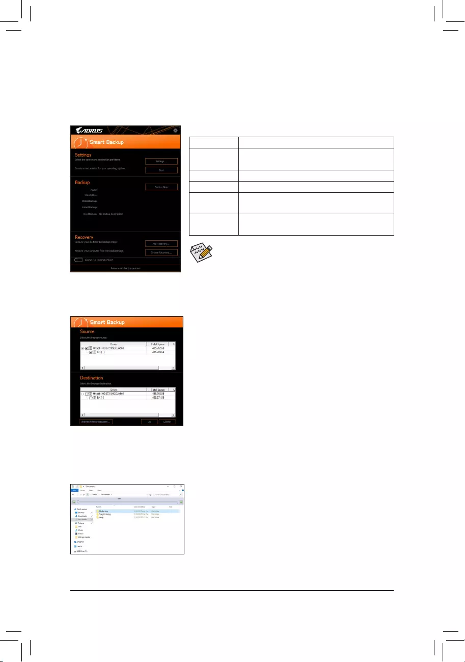
— 87 —
5-2-8 Smart Backup
SmartBackupallowsyoutobackupapartitionasanimageleeveryhour.Youcanusetheseimagestorestore
yoursystemorleswhenneeded.
•SmartBackuponlysupportsNTFSlesystem.
•You need to select the destination partition in Settingsthersttime
you use Smart Backup.
•The Backup Now button will be available only after 10 minutes you
have logged in Windows.
•Select the Always run on next reboot checkbox to automatically
enable Smart Backup after system reboot.
Creating a backup:
Click the Settings button on the main menu. In the Settings dialog
box, select the source partition and destination partition and click OK.
The initial backup will start after 10 minutes and regular backup will be
performed hourly. Note: By default, all partitions on the system drive
are selected as the backup source. The backup destination cannot be
on the same partition as the backup source.
Saving the backup to a network location:
If you want to save the backup to a network location, select Browse
network location. Make sure your computer and the computer where
you want to save the backup are in the same domain. Choose the
network location where you want to store the backup and enter the user
name and password. Follow the on-screen instructions to complete.
Recoveringale:
Click the File Recovery button on the main menu. Use the time slider on
the top of the popped out window to select a previous backup time. The
right pane will display the backed-up partitions in the backup destination
(in the My Backupfolder).Browsetotheleyouwantandcopyit.
The Smart Backup main menu:
Button Description
Settings Allows you to select the source and destination
partition
Start Allows you to create a rescue drive
Backup Now Allows you to perform the backup immediately
File
Recovery…
Allowsyoutorecoveryourlesfromthebackup
image
System
Recovery…
Allows you to recover your system from the
backup image
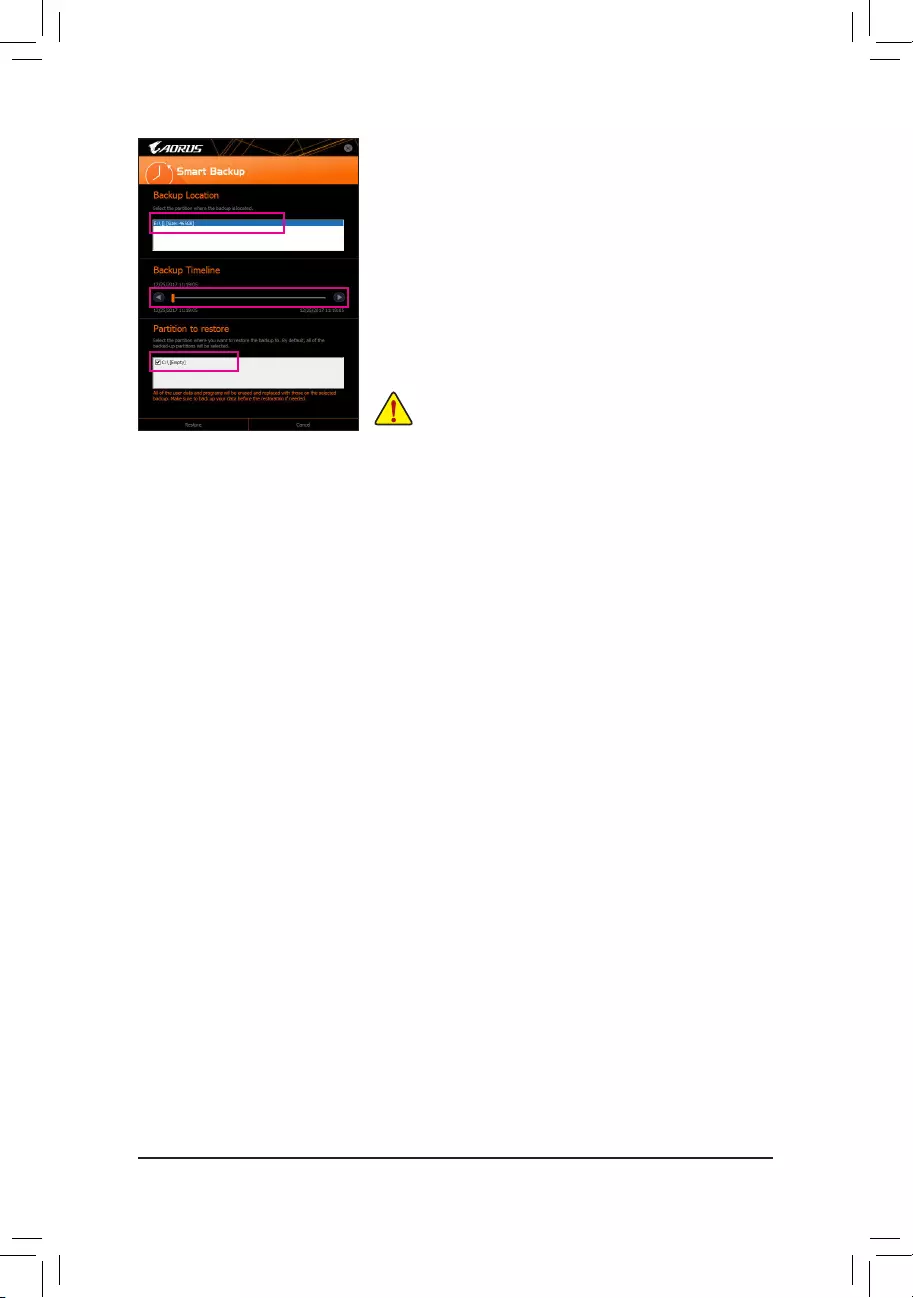
— 88 —
Recovering your system with Smart Backup:
Steps:
1. Click the System Recovery button on the main menu.
2. Select the location where your backup is saved.
3. Use the time slider to select a time point.
4. Select a partition backup created on the selected time point and
click Restore.
5. Conrmwhethertorestartyoursystemtoproceedwiththerestore
immediately or later. Once you respond «Yes» the system will restart to
the Windows recovery environment. Follow the onscreen instructions
to restore your system.
Allofyourlesandprogramswillbedeletedandreplacedwith
those on the selected backup. If needed, be sure to make a
copy of your data before the restore.
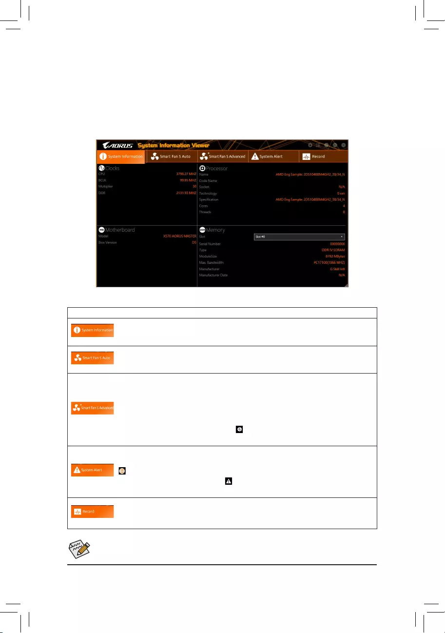
— 89 —
5-2-9 System Information Viewer
GIGABYTE System Information Viewer allows you to monitor and adjust the fan speed in the operating system.
You can also display the hardware monitor information on the desktop to view the system status at any time.
The System Information Viewer Interface
Tabs Information
Tab Description
The System Information tab provides information on the installed CPU, motherboard, and
the BIOS version.
The Smart Fan 5 Auto tab allows you to specify a Smart Fan mode.
The Smart Fan 5 Advanced tab allows you to adjust the smart fan speed. The fans will
run at different speeds according to system temperatures. Using the Smart Fan option you
canadjustthefan’sworkloadaccordingsystemtemperaturesoryoucanxthefanspeeds
using the RPM Fixed Mode option. Click the Calibrate button and the fan speed will be
shown in relation to overall fan workload after calibration. The Reset button can revert the
fan settings back to the last saved values. Noise Detection provides detection of the noise
level (measured in decibels) inside the chassis.
The System Alert tab allows you to monitor hardware temperature, voltage and fan speed,
and set temperature/fan speed alarm.
allows you to select what information to be displayed in quick mode (by default, all of the
hardware information are displayed); allowsyoutoenablealertnotication,clickApply
after selection.
The Record tab allows you to record changes in system voltages, temperatures, fan speeds,
and noise. Please note, the recording will stop if you exit the Record tab during the recording
process.
•The speed control function requires the use of a fan with fan speed control design.
•To use the noise detection function, you must have a motherboard with a noise detection header.
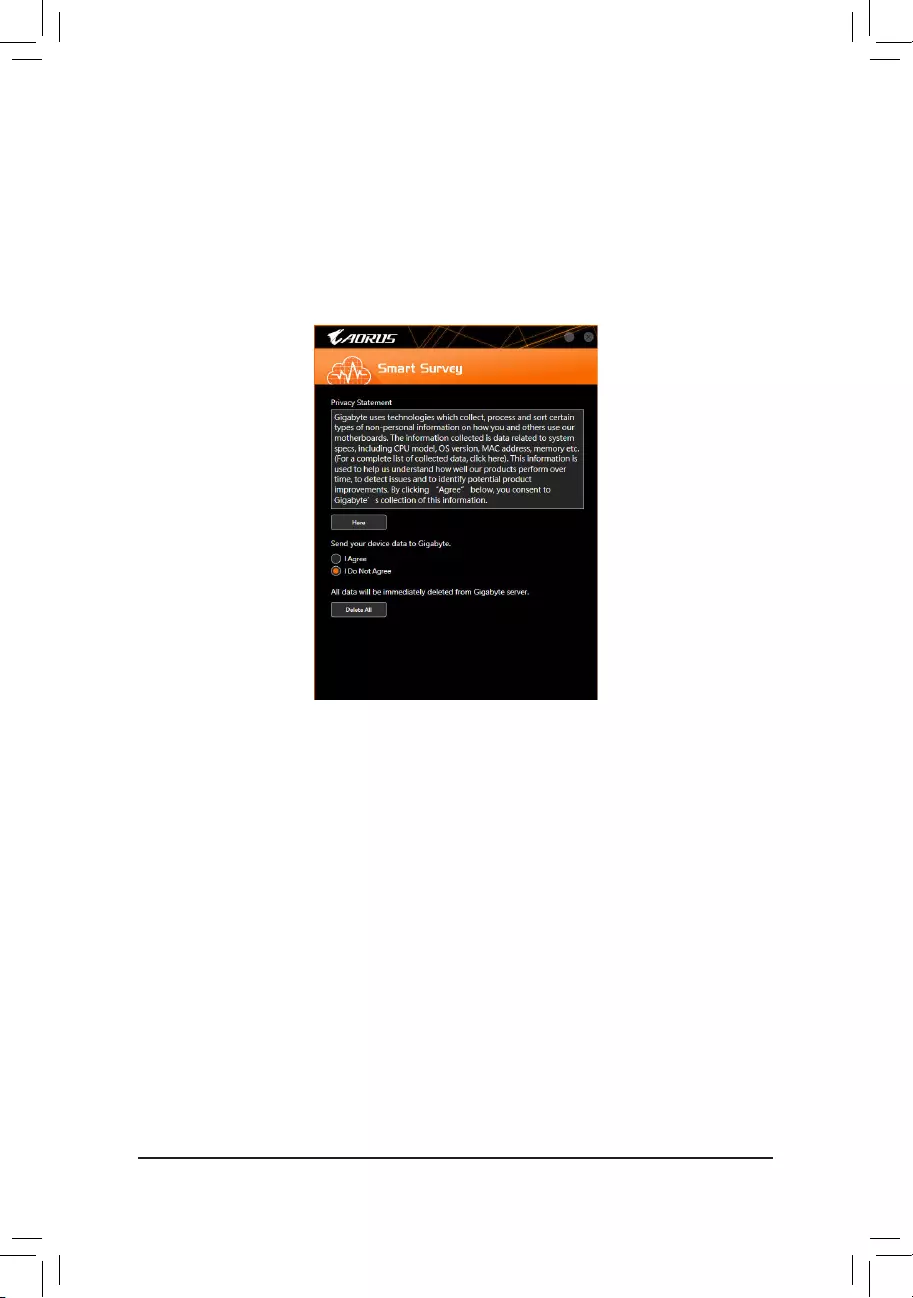
— 90 —
5-2-10 Smart Survey
GIGABYTE Smart Survey collects, processes, and sort certain types of non-personal information on how you
and others use our motherboards. The information collected is data related to system specs, including CPU
model, OS version, MAC address, memory etc. This information is used to help us understand how well our
products perform over time, to detect issues and to identify potential product improvements.
The Smart Survey Interface
Using Smart Survey
•Clicking «Here»:
Allows you to check the complete list of collected data.
•Sending Device Data to GIGABYTE:
Selecting I Agree means you consent to GIGABYTE’s collection of your device data. Smart Survey will not
collect any data if you select I Do Not Agree.
•Clicking «Delete All»:
All data will be immediately deleted from Gigabyte server.
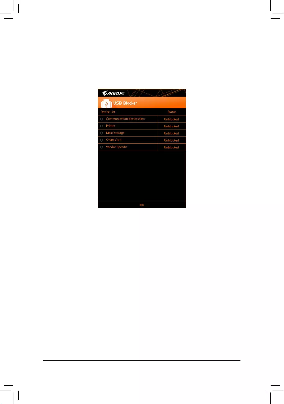
— 91 —
5-2-11 USB Blocker
GIGABYTE USB Blocker provides you with an easy-to-use interface that allows you to block certain USB device
types on your PC. Devices classes that are blocked will be ignored by the operating system.
The USB Blocker Interface
Using USB Blocker
Select the class of USB device that you would like to block or unblock. Double left-click to change the Blocked
or Unblocked status and click OK. Then enter your password and click OK to complete.
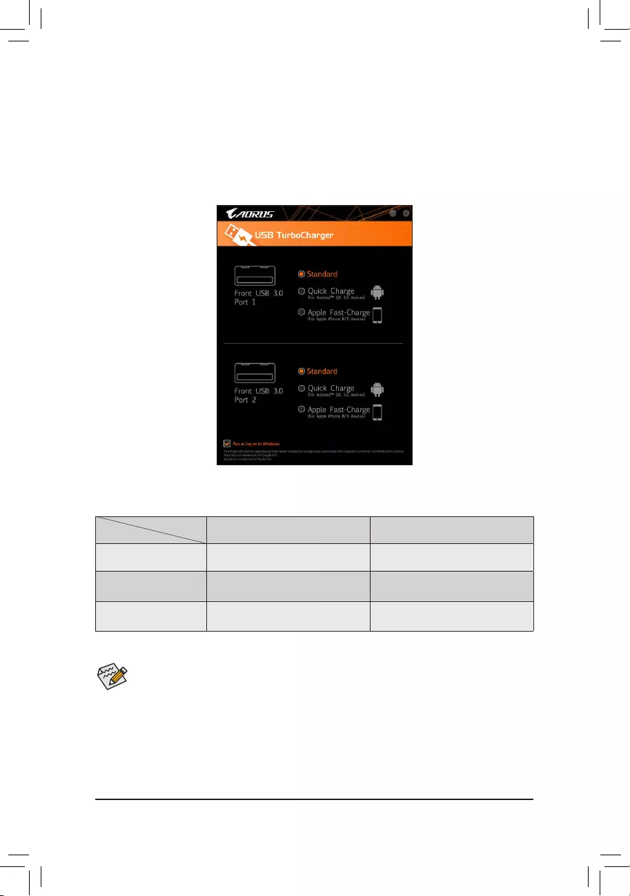
— 92 —
5-2-12 USB TurboCharger
GIGABYTE USB TurboCharger supports the quick charging technologies (Note 1) of Apple’s and Android™
QC 3.0’s smart phones/tablet devices. It allows you to quick-charge your device(s) connected to the front
USB 3.1 Gen 1 type A port (s) with the required mode.
The USB TurboCharger Interface
Using USB TurboCharger
The quick-charging performance of each connector may vary by the device used. Refer to the table below to
select a proper way to charge:
Apple Android™ QC 3.0
Standard Used as a normal USB 3.1 Gen 1 port Used as a normal USB 3.1 Gen 1 port
Quick Charge (Note 2) a
* Provides maximum output power of 10 W
a
* Provides maximum output power of 18 W
Apple Fast Charge (Note 3) a
* Provides maximum output power of 15 W r
a: Supports quick-charge, r: Not support quick-charge.
While the system is in S3/S4, the Quick Charge and Apple Fast-Charge modes can only deliver 5V
standby power, and the two front USB ports together can provide a total power of up to 10 W and do
not support PME Event Wake Up function.
(Note 1) Quick-charging protocols supported: Apple and Samsung®dividerchargingproleat5V@2.4Aand
5V@2A, Qualcomm® Quick Charge 3.0™at3.6V~12V(QC3.0),backwardcompatibleQuickCharge
2.0™at5V/9V/12V(QC2.0),BatteryChargingSpecicationv1.2DCP5V@1.5A.
(Note2) Theletransferfunctionisnotsupportedinthismode.
(Note 3) This is the recommended mode when Apple iPhone 8 / iPhone 8 plus / iPhone X is connected.
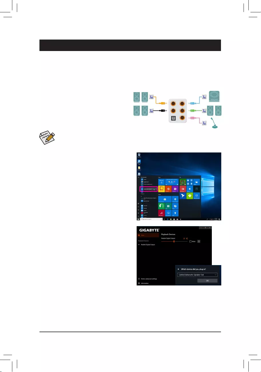
— 93 —
Chapter 6 Appendix
6-1 ConguringAudioInputandOutput
A. Configuring Speakers
Step 1:
Go to the Start menu click the Realtek Audio Console.
(Note) 2/4/5.1/7.1-Channel Audio Configurations:
Refer to the following for multi-channel speaker configurations.
•2-channel audio: Headphone or Line out.
•4-channel audio: Front speaker out and Rear speaker out.
•5.1-channel audio: Front speaker out, Rear speaker out, and Center/Subwoofer speaker out.
•7.1-channel audio: Front speaker out, Rear speaker out, Center/Subwoofer speaker out, and Side speaker out.
To configure 4/5.1/7.1-channel audio, you have to retask either the Line in or Mic in jack to be Side
speaker out through the audio driver.
6-1-1 Conguring2/4/5.1/7.1-ChannelAudio
The motherboard provides five audio jacks on the back
panel which support 2/4/5.1/7.1-channel (Note) audio.
The picture to the right shows the default audio jack
assignments.
Center/Subwoofer
Speaker Out Line In
Rear Speaker Out Front Speaker Out
Mic In
Step 2:
Connect an audio device to an audio jack. The Which
device did you plut in ? dialog box appears. Select
the device according to the type of device you connect.
Then click OK.
After you install the included motherboard drivers, make sure your Internet connection works properly. the system
will automatically install the audio driver from Microsoft Store. Restart the system after the audio driver is installed.
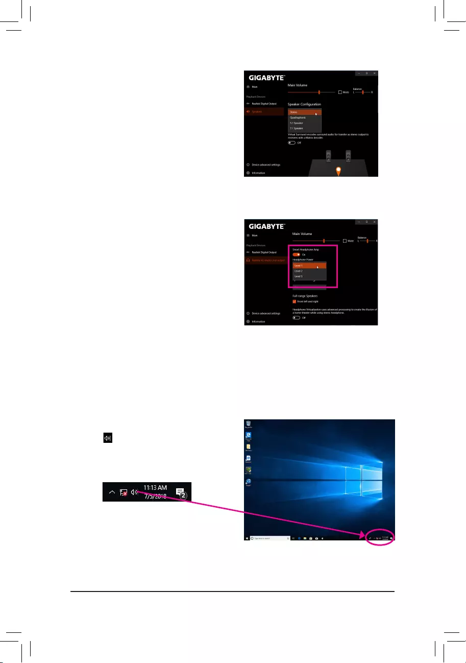
— 94 —
Step 3:
On the Speakers screen, click the Speaker Configuration
tab. In the Speaker Configuration list, select Stereo,
Quadraphonic, 5.1 Speaker, or 7.1 Speaker according
to the type of speaker configuration you wish to set up.
Then the speaker setup is completed.
B. Configuring Sound Effect
You may configure an audio environment on the Speakers tab.
C. Enabling Smart Headphone Amp
The Smart Headphone Amp feature automatically detects
impedance of your head-worn audio device, whether
earbuds or high-end headphones to provide optimal
audio dynamics. To enable this feature, connect your
head-worn audio device to the Line out jack on the front
panel and then go to the Realtek HD Audio 2nd output
page. Enable the Smart Headphone Amp feature. The
Headphone Power list below allows you to manually set
the level of headphone volume, preventing the volume
from being too high or too low.
Step 1:
Locate the icon in the notification area and right-click
on this icon. Select Sounds.
* Configuring the Headphone
When you connect your headphone to the Line out jack on the back panel or front panel, make sure the default
playback device is configured correctly.
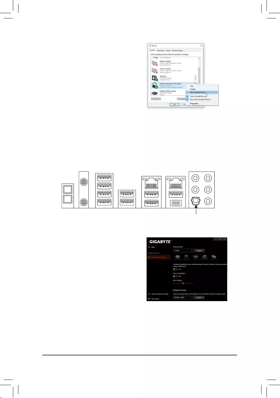
— 95 —
The S/PDIF Out jack can transmit audio signals to an external decoder for decoding to get the best audio quality.
1. Connecting a S/PDIF Out Cable:
Connect a S/PDIF optical cable to an external decoder for transmitting the S/PDIF digital audio signals.
Connects to a S/PDIF optical cable
6-1-2 ConguringS/PDIFOut
Step 2:
On the Playback tab, make sure your headphone is set
as the default playback device. For the device connected
to the Line out jack on the back panel, right-click on
Speakers and select Set as Default Device; for the
device connected to the Line out jack on the front panel,
right-click on Realtek HD Audio 2nd output.
2. Configuring S/PDIF Out:
On the Realtek Digital Output screen, Select the sample
rate and bit depth in the Default Format section.
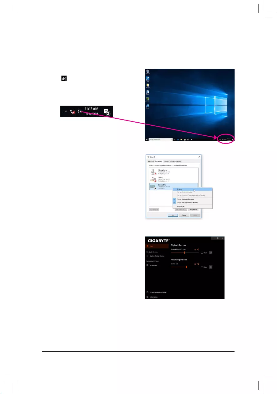
— 96 —
6-1-3 Stereo Mix
Step 1:
Locate the icon in the notification area and right-click
on this icon. Select Sounds.
The following steps explain how to enable Stereo Mix (which may be needed when you want to record sound
from your computer).
Step 2:
On the Recording tab, right-click on Stereo Mix item and
select Enable. Then set it as the default device. (if you do
not see Stereo Mix, right-click on an empty space and
select Show Disabled Devices.)
Step 3:
Now you can access the HD Audio Manager to configure
Stereo Mix and use Voice Recorder to record the sound.
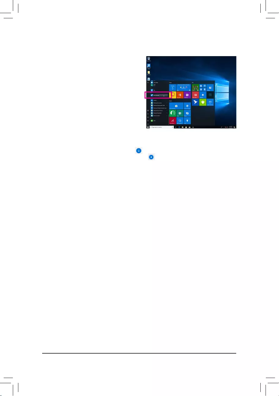
— 97 —
6-1-4 Using the Voice Recorder
A. Recording Audio
1. To begin the recording, click the Record icon .
2. To stop the recording, click the Stop recording icon .
B. Playing the Recorded Sound
The recordings will saved in Documents>Sound Recordings. Voice Recorder records audio in MPEG-4 (.m4a)
format. You can play the recording with a digital media player program that supports the audio file format.
After setting up the audio input device, to open the
Voice Recorder, go to the Start menu and search for
Voice Recorder.

— 98 —
6-2 Troubleshooting
6-2-1 Frequently Asked Questions
To read more FAQs for your motherboard, please go to the Support\FAQ page on GIGABYTE’s website.
Q: Why is the light of my keyboard/optical mouse still on after the computer shuts down?
A: Some motherboards provide a small amount of standby power after the computer shuts down and that’s why the light is still
on.
Q: How do I clear the CMOS values?
A: For motherboards that have a Clear CMOS button, press this button to clear the CMOS values (before doing this, please
turn off the computer and unplug the power cord). For motherboards that have a Clear CMOS jumper, refer to the instruc-
tions in Chapter 1 to short the jumper to clear the CMOS values. If your board doesn’t have this jumper/button, refer to the
instructions on the motherboard battery in Chapter 1. You can temporarily remove the battery from the battery holder to stop
supplying power to the CMOS, which will clear the CMOS values after about one minute.
Q: Why do I still get a weak sound even though I have turned my speaker to the maximum volume?
A: Makesureyourspeakerisequippedwithaninternalamplier.Ifnot,tryaspeakerwithpower/amplier.
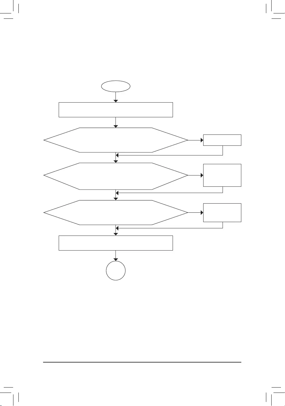
— 99 —
6-2-2 Troubleshooting Procedure
If you encounter any troubles during system startup, follow the troubleshooting procedure below to solve the
problem.
START
A
Turn off the power. Remove all peripherals, connecting cables, and
power cord etc.
Isolate the short circuit.
Secure the CPU cooler
on the CPU. Connect the
CPU cooler power cable
to the motherboard.
Correctly insert the
memory into the memory
socket.
(Continued…)
Yes
Theproblemisveriedandsolved.
Theproblemisveriedandsolved.
Theproblemisveriedandsolved.
No
No
No
Yes
Yes
Insert the graphics card. Connect the ATX main power cable and the
12V power cable. Turn on the power to start the computer.
Make sure the motherboard does not short-circuit with the chassis or
other metal objects.
Check if the CPU cooler is attached to the CPU securely. Is the
power connector of the CPU cooler connected to the CPU_FAN
header properly?
Check if the memory is installed properly on the memory slot.
Make sure the graphics card is securely seated in the
expansion slot and power connectors are firmly attached.
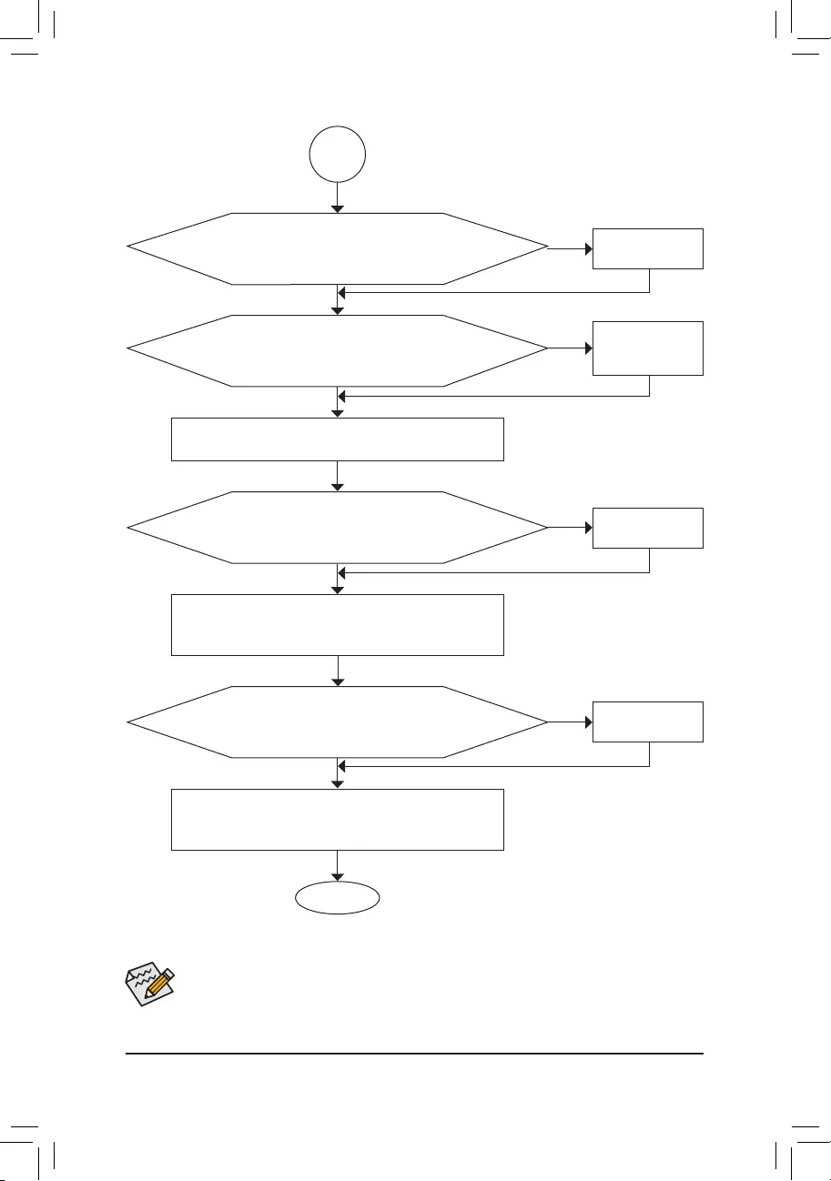
— 100 —
If the procedure above is unable to solve your problem, contact the place of purchase or local dealer
for help. Or go to the Support\Technical Support page to submit your question. Our customer service
staff will reply you as soon as possible.
The power supply, CPU or
CPU socket might fail.
The keyboard or keyboard
connector might fail.
END
A
Turn off the computer. Plug in the keyboard and mouse and restart
the computer.
The graphics card,
expansion slot, or monitor
might fail.
The hard drive, connector,
or cable might fail.
No
Theproblemisveriedandsolved.
Theproblemisveriedandsolved.
Theproblemisveriedandsolved.
No
No
Yes
Yes
Yes
Reinstall the operating system. Reinstall other devices one by one
(install one device at one time and then boot the system to see if the
device works successfully).
Press <Delete> to enter BIOS Setup. Select «Load Optimized Defaults.»
Select «Save & Exit Setup» to save changes and exit BIOS Setup.
Check if there is display on your monitor.
When the computer is turned on, is the CPU cooler running?
Check if the keyboard is working properly.
No
Theproblemisveriedandsolved.
Yes
Turn off the computer and connect the hard drive(s). Check if the system
can boot successfully.

— 101 —
6-3 Debug LED Codes
Code Description
10 PEI Core is started.
11 Pre-memory CPU initialization is started.
12~14 Reserved.
15 Pre-memory North-Bridge initialization is started.
16~18 Reserved.
19 Pre-memory South-Bridge initialization is started.
1A~2A Reserved.
2B~2F Memory initialization.
31 Memory installed.
32~36 CPU PEI initialization.
37~3A IOH PEI initialization.
3B~3E PCH PEI initialization.
3F~4F Reserved.
60 DXE Core is started.
61 NVRAM initialization.
62 Installation of the PCH runtime services.
63~67 CPU DXE initialization is started.
68 PCI host bridge initialization is started.
69 IOH DXE initialization.
6A IOH SMM initialization.
6B~6F Reserved.
70 PCH DXE initialization.
71 PCH SMM initialization.
72 PCH devices initialization.
73~77 PCH DXE initialization (PCH module specific).
78 ACPI Core initialization.
79 CSM initialization is started.
7A~7F Reserved for AMI use.
80~8F Reserved for OEM use (OEM DXE initialization codes).
90 Phase transfer to BDS (Boot Device Selection) from DXE.
91 Issue event to connect drivers.
Regular Boot

— 102 —
Code Description
92 PCI Bus initialization is started.
93 PCI Bus hot plug initialization.
94 PCI Bus enumeration for detecting how many resources are requested.
95 Check PCI device requested resources.
96 Assign PCI device resources.
97 Console Output devices connect (ex. Monitor is lighted).
98 Console input devices connect (ex. PS2/USB keyboard/mouse are activated).
99 Super IO initialization.
9A USB initialization is started.
9B Issue reset during USB initialization process.
9C Detect and install all currently connected USB devices.
9D Activated all currently connected USB devices.
9E~9F Reserved.
A0 IDE initialization is started.
A1 Issue reset during IDE initialization process.
A2 Detect and install all currently connected IDE devices.
A3 Activated all currently connected IDE devices.
A4 SCSI initialization is started.
A5 Issue reset during SCSI initialization process.
A6 Detect and install all currently connected SCSI devices.
A7 Activated all currently connected SCSI devices.
A8 Verify password if needed.
A9 BIOS Setup is started.
AA Reserved.
AB Wait user command in BIOS Setup.
AC Reserved.
AD Issue Ready To Boot event for OS Boot.
AE Boot to Legacy OS.
AF Exit Boot Services.
B0 Runtime AP installation begins.
B1 Runtime AP installation ends.
B2 Legacy Option ROM initialization.
B3 System reset if needed.
— 103 —
Code Description
B4 USB device hot plug-in.
B5 PCI device hot plug.
B6 Clean-up of NVRAM.
B7 Reconfigure NVRAM settings.
B8~BF Reserved.
C0~CF Reserved.
Code Description
E0 S3 Resume is started (called from DXE IPL).
E1 Fill boot script data for S3 resume.
E2 Initializes VGA for S3 resume.
E3 OS S3 wake vector call.
S3 Resume
Code Description
F0 Recovery mode will be triggered due to invalid firmware volume detection.
F1 Recovery mode will be triggered by user decision.
F2 Recovery is started.
F3 Recovery firmware image is found.
F4 Recovery firmware image is loaded.
F5~F7 Reserved for future AMI progress codes.
Recovery
Code Description
50~55 Memory initialization error occurs.
56 Invalid CPU type or speed.
57 CPU mismatch.
58 CPU self test failed or possible CPU cache error.
59 CPU micro-code is not found or micro-code update is failed.
5A Internal CPU error.
5B Reset PPI is failed.
5C~5F Reserved.
D0 CPU initialization error.
D1 IOH initialization error.
Error

— 104 —
Code Description
D2 PCH initialization error.
D3 Some of the Architectural Protocols are not available.
D4 PCI resource allocation error. Out of Resources.
D5 No Space for Legacy Option ROM initialization.
D6 No Console Output Devices are found.
D7 No Console Input Devices are found.
D8 It is an invalid password.
D9~DA Can’t load Boot Option.
DB Flash update is failed.
DC Reset protocol is failed.
DE~DF Reserved.
E8 S3 resume is failed.
E9 S3 Resume PPI is not found.
EA S3 Resume Boot Script is invalid.
EB S3 OS Wake call is failed.
EC~EF Reserved.
F8 Recovery PPI is invalid.
F9 Recovery capsule is not found.
FA Invalid recovery capsule.
FB~FF Reserved.
— 105 —
Regulatory Statements
Regulatory Notices
This document must not be copied without our written permission, and the contents there of must not be imparted to a
third party nor be used for any unauthorized purpose.
Contravention will be prosecuted. We believe that the information contained herein was accurate in all respects at the
time of printing. GIGABYTE cannot, however, assume any responsibility for errors or omissions in this text. Also note
that the information in this document is subject to change without notice and should not be construed as a commitment
by GIGABYTE.
Our Commitment to Preserving the Environment
In addition to high-efficiency performance, all GIGABYTE motherboards fulfill European Union regulations for RoHS
(Restriction of Certain Hazardous Substances in Electrical and Electronic Equipment) and WEEE (Waste Electrical and
Electronic Equipment) environmental directives, as well as most major worldwide safety requirements. To prevent releases
of harmful substances into the environment and to maximize the use of our natural resources, GIGABYTE provides the
following information on how you can responsibly recycle or reuse most of the materials in your «end of life» product.
Restriction of Hazardous Substances (RoHS) Directive Statement
GIGABYTE products have not intended to add and safe from hazardous substances (Cd, Pb, Hg, Cr+6, PBDE and
PBB). The parts and components have been carefully selected to meet RoHS requirement. Moreover, we at GIGABYTE
are continuing our efforts to develop products that do not use internationally banned toxic chemicals.
Waste Electrical & Electronic Equipment (WEEE) Directive Statement
GIGABYTE will fulfill the national laws as interpreted from the 2012/19/EU WEEE (Waste Electrical and Electronic
Equipment) directive. The WEEE Directive specifies the treatment, collection, recycling and disposal of electric and
electronic devices and their components. Under the Directive, used equipment must be marked, collected separately,
and disposed of properly.
WEEE Symbol Statement
The symbol shown below is on the product or on its packaging, which indicates that this product must
not be disposed of with other waste. Instead, the device should be taken to the waste collection centers
for activation of the treatment, collection, recycling and disposal procedure. The separate collection and
recycling of your waste equipment at the time of disposal will help to conserve natural resources and ensure
that it is recycled in a manner that protects human health and the environment. For more information about where you
can drop off your waste equipment for recycling, please contact your local government office, your household waste
disposal service or where you purchased the product for details of environmentally safe recycling.
When your electrical or electronic equipment is no longer useful to you, «take it back» to your local or regional waste
collection administration for recycling.
If you need further assistance in recycling, reusing in your «end of life» product, you may contact us at the Customer
Care number listed in your product’s user’s manual and we will be glad to help you with your effort.
Finally, we suggest that you practice other environmentally friendly actions by understanding and using the energy-saving
features of this product (where applicable), recycling the inner and outer packaging (including shipping containers) this
product was delivered in, and by disposing of or recycling used batteries properly. With your help, we can reduce the
amount of natural resources needed to produce electrical and electronic equipment, minimize the use of landfills for
the disposal of «end of life» products, and generally improve our quality of life by ensuring that potentially hazardous
substances are not released into the environment and are disposed of properly.
Battery Information
European Union—Disposal and recycling information
GIGABYTE Recycling Program (available in some regions)
This symbol indicates that this product and/or battery should not be disposed of with household waste. You must use
the public collection system to return, recycle, or treat them in compliance with the local regulations.

— 106 —
FCC Notice (U.S.A. Only)
Operation is subject to the following two conditions: (1) this device may not cause harmful interference, and (2)
this device must accept any interference received, including interference that may cause undesired operation.
WARNING: This equipment has been tested and found to comply with the limits for a Class B digital device,
pursuant to Part 15 of the FCC Rules. These limits are designed to provide reasonable protection against harmful
interference in a residential installation.
This equipment generates and radiates radio frequency energy and, if not installed and used in accordance
with the instructions, may cause harmful interference to radio communications.
However, there is no guarantee that interference will not occur in a particular installation. If this equipment does
cause harmful interference to radio or television reception, which can be determined by turning the equipment
off and on, the user is encouraged to try to correct the interference by one or more of the following measures:
•Reorient or relocate the receiving antenna.
•Increase the separation between the equipment and receiver.
•Connect the equipment into an outlet on a circuit different from that to which the receiver is connected.
•Consult a dealer or experienced TV/radio technician for help.
The user may find the following booklet prepared by the Federal Communications Commission helpful:
The Interference Handbook.
This booklet is available from the U.S. Government Printing Office, Washington, D.C.20402. Stock No.004-
000-00345-4
Notice for 5GHz
Operations in the 5.15-5.25GHz band are restricted to indoor usage only. (For 5GHz only)
RF exposure statement
The product comply with the FCC portable RF exposure limit set forth for an uncontrolled environment and are
safe for intended operation as described in this manual. The further RF exposure reduction can be achieved if
the product can be kept as far as possible from the user body or set the device to lower output power if such
function is available.
CAUTION:
The manufacturer is not responsible for any interference caused by unauthorized
modifications and/or use of unauthorized antennas.
Such changes and/or modifications not expressly approved by the party responsible for
compliance of this device could void the user’s authority to operate the equipment.

— 107 —
Canada-Industry Canada (IC):
This device complies with Canadian RSS-210.
This device complies with Industry Canada license-exempt RSS standard(s). Operation is subject to the
following two conditions:
(1) this device may not cause interference, and
(2) this device must accept any interference, including interference that may cause undesired operation of
the device.
Ce dispositif est conforme à la norme CNR-210 d’Industrie Canada applicable aux appareils radio exempts de
licence. Son fonctionnement est sujet aux deux conditions suivantes:
(1) le dispositif ne doit pas produire de brouillage préjudiciable, et
(2) ce dispositif doit accepter tout brouillage reçu, y compris un brouillage susceptible de provoquer un
fonctionnement indésirable.
Notice for 5GHz:
Caution :
(i) the device for operation in the band 5150-5250 MHz is only for indoor use to reduce the potential for harmful
interference to co-channel mobile satellite systems;
(ii) the maximum antenna gain permitted for devices in the bands 5250-5350 MHz and 5470-5725 MHz shall
comply with the e.i.r.p. limit; and
(iii) the maximum antenna gain permitted for devices in the band 5725-5825 MHz shall comply with the e.i.r.p.
limits specified for point-to-point and non point-to-point operation as appropriate.
(iv) Users should also be advised that high-power radars are allocated as primary users (i.e. priority users)
of the bands 5250-5350 MHz and 5650-5850 MHz and that these radars could cause interference and/or
damage to LE-LAN devices.
Avertissement:
Le guide d’utilisation des dispositifs pour réseaux locaux doit inclure des instructions précises sur les restrictions
susmentionnées, notamment :
(i) les dispositifs fonctionnant dans la bande 5 150-5 250 MHz sont réservés uniquement pour une utilisation à
l’intérieur afin de réduire les risques de brouillage préjudiciable aux systèmes de satellites mobiles utilisant
les mêmes canaux;
(ii) le gain maximal d’antenne permis pour les dispositifs utilisant les bandes 5 250-5 350 MHz et 5 470-5 725
MHz doit se conformer à la limite de p.i.r.e.;
(iii) le gain maximal d’antenne permis (pour les dispositifs utilisant la bande 5 725-5 825 MHz) doit se conformer
à la limite de p.i.r.e. spécifiée pour l’exploitation point à point et non point à point, selon le cas.
(iv) De plus, les utilisateurs devraient aussi être avisés que les utilisateurs de radars de haute puissance sont
désignés utilisateurs principaux (c.-à-d., qu’ils ont la priorité) pour les bandes 5 250-5 350 MHz et 5 650-5
850 MHz et que ces radars pourraient causer du brouillage et/ou des dommages aux dispositifs LAN-EL.
Radiation Exposure Statement:
The product comply with the Canada portable RF exposure limit set forth for an uncontrolled environment and
are safe for intended operation as described in this manual. The further RF exposure reduction can be achieved
if the product can be kept as far as possible from the user body or set the device to lower output power if such
function is available.

— 108 —
European Community Radio Equipment Directive (RED) Compliance Statement:
This equipment complies with all the requirements and other relevant provisions of Radio Equipment Directive
2014/53/EU.
This equipment is suitable for home and office use in all the European Community Member States and EFTA
Member States.
The low band 5.15 -5.35 GHz is for indoor use only.
Restrictions d’utilisation en France:
Pour la France métropolitaine
2.400 — 2.4835 GHz (Canaux 1à 13) autorisé en usage intérieur
2.400 — 2.454 GHz (canaux 1 à 7) autorisé en usage extérieur
Pour la Guyane et la Réunion
2.400 — 2.4835 GHz (Canaux 1à 13) autorisé en usage intérieur
2.420 — 2.4835 GHz (canaux 5 à 13) autorisé en usage extérieur
Notice for Italy:
The use of these equipments is regulated by:
1. D.L.gs 1.8.2003, n. 259, article 104 (activity subject to general authorization) for outdoor use and article
105 (free use) for indoor use, in both cases for private use.
2. D.M. 28.5.03, for supply to public of RLAN access to networks and telecom services. L’uso degli apparati
è regolamentato da:
1. D.L.gs 1.8.2003, n. 259, articoli 104 (attività soggette ad autorizzazione generale) se utilizzati al di fuori
del proprio fondo e 105 (libero uso) se utilizzati entro il proprio fondo, in entrambi i casi per uso private.
2. D.M. 28.5.03, per la fornitura al pubblico dell’accesso R-LAN alle reti e ai servizi di telecomunicazioni.
Taiwan NCC Wireless Statements / 無線設備警告聲明:
低功率電波輻射性電機管理辦法
第十二條: 經型式認證合格之低功率射頻電機,非經許可,公司、商號或使用者均不得擅自變更頻
率、加大功率或變更原設計之特性及功能。
第十四條: 低功率射頻電機之使用不得影響飛航安全及干擾合法通信;經發現有干擾現象時,應立
即停用,並改善至無干擾時方得繼續使用。前項合法通信,指依電信法規定作業之無線
電通信。低功率射頻電機須忍受合法通信或工業、科學及醫療用電波輻射性電機設備之
干擾。
在5.25-5.35秭赫頻帶內操作之無線資訊傳輸設備,限於室內使用。
Korea KCC NCC Wireless Statement:
5,25 GHz — 5,35 GHz 대역을 사용하는 무선 장치는 실내에서만 사용하도록 제한됩니다。
Japan Wireless Statement:
5.15GHz帯~5.35GHz帯: 屋内のみの使用。

— 109 —

— 110 —

— 111 —
Contact Us
•GIGA-BYTE TECHNOLOGY CO., LTD.
Address: No.6, Baoqiang Rd., Xindian Dist.,
New Taipei City 231, Taiwan
TEL: +886-2-8912-4000
FAX: +886-2-8912-4005
Tech. and Non-Tech. Support (Sales/Marketing) :
https://esupport.gigabyte.com
WEB address (English): https://www.gigabyte.com
WEB address (Chinese): https://www.gigabyte.com/tw
•G.B.T. INC. — U.S.A.
TEL: +1-626-854-9338
FAX: +1-626-854-9326
Tech. Support: https://esupport.gigabyte.com
Warranty Info: http://rma.gigabyte.us
Web address: https://www.gigabyte.com/us
•G.B.T. INC (USA) — Mexico
Tel: +1-626-854-9338 x 215 (Soporte de habla hispano)
FAX: +1-626-854-9326
Correo: soporte@gigabyte-usa.com
Tech. Support: http://rma.gigabyte.us
Web address: https://www.gigabyte.com/latam
•Giga-Byte SINGAPORE PTE. LTD. — Singapore
WEB address : https://www.gigabyte.com/sg
•Thailand
WEB address : https://www.gigabyte.com/th
•Vietnam
WEB address : https://www.gigabyte.com/vn
•NINGBO G.B.T. TECH. TRADING CO., LTD. — China
WEB address : http://www.gigabyte.cn
Shanghai
TEL: +86-21-63400912
FAX: +86-21-63400682
Beijing
TEL: +86-10-62102838
FAX: +86-10-62102848
Wuhan
TEL: +86-27-87685981
FAX: +86-27-87579461
GuangZhou
TEL: +86-20-87540700
FAX: +86-20-87544306
Chengdu
TEL: +86-28-85483135
FAX: +86-28-85256822
Xian
TEL: +86-29-85531943
FAX: +86-29-85510930
Shenyang
TEL: +86-24-83992342
FAX: +86-24-83992102
•GIGABYTE TECHNOLOGY (INDIA) LIMITED — India
WEB address : https://www.gigabyte.com/in
•Saudi Arabia
WEB address : https://www.gigabyte.com/sa
•Gigabyte Technology Pty. Ltd. — Australia
WEB address : https://www.gigabyte.com/au

— 112 —
•G.B.T. TECHNOLOGY TRADING GMBH — Germany
WEB address : https://www.gigabyte.com/de
•G.B.T. TECH. CO., LTD. — U.K.
WEB address : https://www.gigabyte.com/uk
•Giga-Byte Technology B.V. — The Netherlands
WEB address : https://www.gigabyte.com/nl
•GIGABYTE TECHNOLOGY FRANCE — France
WEB address : https://www.gigabyte.com/fr
•Sweden
WEB address : https://www.gigabyte.com/se
•Italy
WEB address : http://it.gigabyte.com/
•Spain
WEB address : http://es.gigabyte.com/
•Greece
WEB address : http://www.gigabyte.com.gr
•Czech Republic
WEB address : http://www.gigabyte.cz
•Hungary
WEB address : http://hu.gigabyte.com/
•Turkey
WEB address : http://www.gigabyte.com.tr
•Russia
WEB address : http://www.gigabyte.ru
•Poland
WEB address : http://www.gigabyte.pl
•Ukraine
WEB address : http://www.gigabyte.ua
•Romania
WEB address : https://www.gigabyte.com/ro
•Serbia
WEB address : http://www.gigabyte.rs/
•Kazakhstan
WEB address : http://www.gigabyte.kz
•GIGABYTE eSupport
To submit a technical or non-technical (Sales/Marketing) question, please link to:
https://esupport.gigabyte.com
GIGABYTE
Loading…
W
- W270BUQ
- W281-G40
- W348M
- W431U
- W451U3
- W466
- W466U2
- W468N
- W480M Vision W
- W480 Vision D
- W480 Vision W
- W511 Series2
- W536M
- W5513
- W552U
- W566
- W566N
- W566U/N2
- W566UW566N
- W576
- WATER FORCE
X
- X1116
- X299 AORUS Gaming 72
- X299 AORUS Gaming 9
- X299 Aorus Master
- X299 AORUS ULTRA GAMING2
- X299 AORUS ULTRA GAMING PRO
- X299 Designare EX
- X299 UD4 Pro
- X299-WU8
- X299X AORUS MASTER2
- X299X Aorus Xtreme Waterforce
- X299X DESIGNARE 10G2
- X299X DESIGNARE 10G GA
- X38-DQ6
- X399 AORUS Gaming 7
- X399 Aorus Pro
- X399 Aorus Xtreme
- X399 Designare EX
- X470 AORUS GAMING 5 WIFI
- X470 AORUS GAMING 7 WIFI
- X470 AORUS ULTRA GAMING
- X48-DQ6
- X48-DS5
- X48T-DQ6
- X5703
- X570 Aorus elite
- X570 Aorus Master
- X570 AORUS MASTER (rev. 1.0)
- X570 Aorus Ultra
- X570 Aorus Xtreme2
- X570 GAMING X
- X570 I Aorus Pro WIFI
- X570 UD
- X58A-UD3R
- X99-Gaming 5
- X99-UD7 WIFI
- XA2CB3
- XA3CB4
- Xeon Processor Motherboard GA-5YXS-RH
- X.H.D
- XM3002
- XP-K7S748
- XP-K7V400
- XP-K7V600
- XP-K7VM333
- XP-K8U-X2
- XP-M5I915GV
- XP-M5S661GX
- XP-M5VM800
- XP-M5VM800MB-MB
- XP-M5VM800P
- XP-M8ARD480A
- XP-M8S761GX
- xp-m8vm800
- X-POWER8
- XPower GH-PSU11-PD
- XP-P4I533E
- XP-P4I533PE
- XP-P4IM533G-HP
- XP-P4IM533GV2
- XP-P4IM800GV
- XP-P4IM800PE
- XP-P4S8X-VM
- XP-P4SM533
- XP-P4VM533
- XP-P5CM
- XP-P5CM-GL
- XP-P5CM-GV
- XP-P5IM800GV-DG
- XP-P5IM800P2
- XV-S25128D
- XV-S27256D
Z
- Z370
- Z370 AORUS GAMING 5
- Z370 Aorus Gaming K3
- Z370 AORUS Ultra Gaming
- Z370 Aorus Ultra Gaming WIFI
- Z370 Aorus Ultra Gaming WIFI-OP
- Z370 HD33
Loading…
Loading…
Nothing found
X570 AORUS MASTER (rev. 1.0)
User manual
104 pgs41.22 Mb1
Table of contents
Loading…
…
GIGABYTE User manual
Download
Specifications and Main Features
Frequently Asked Questions
User Manual
 User manual")
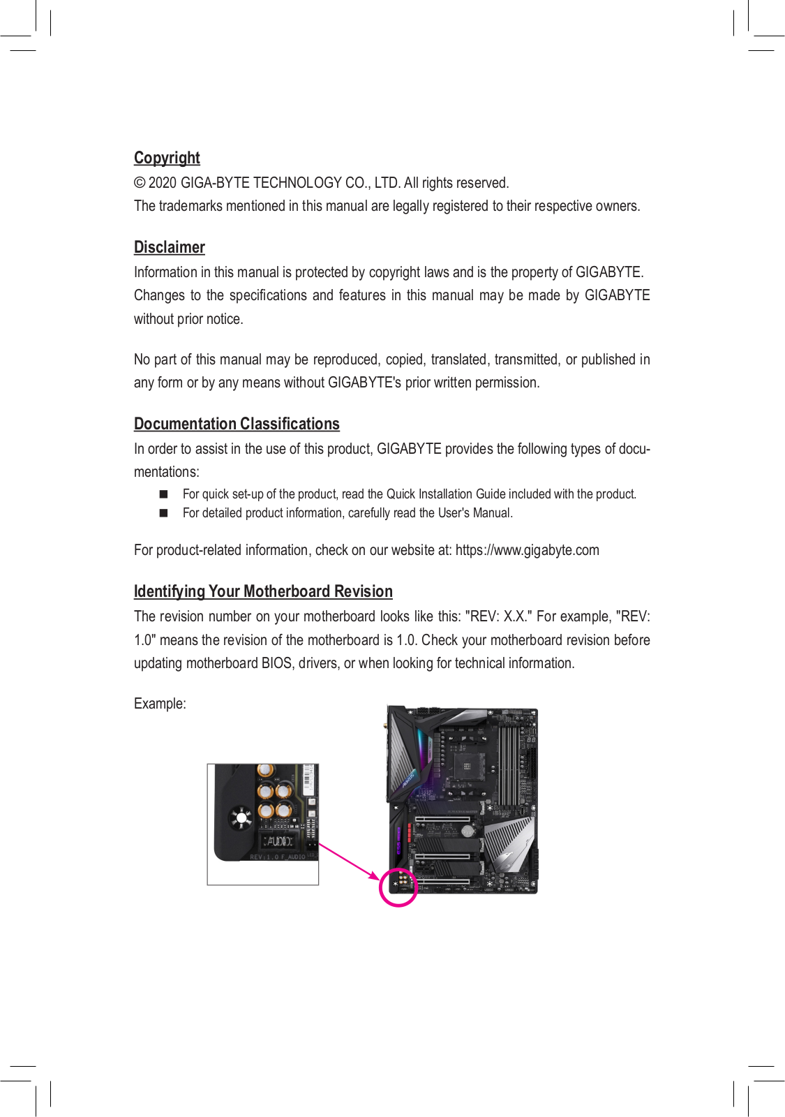
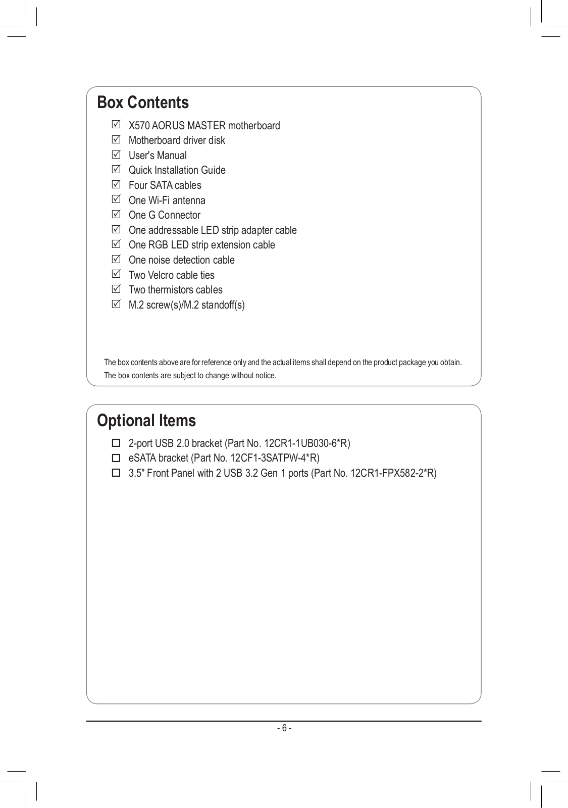
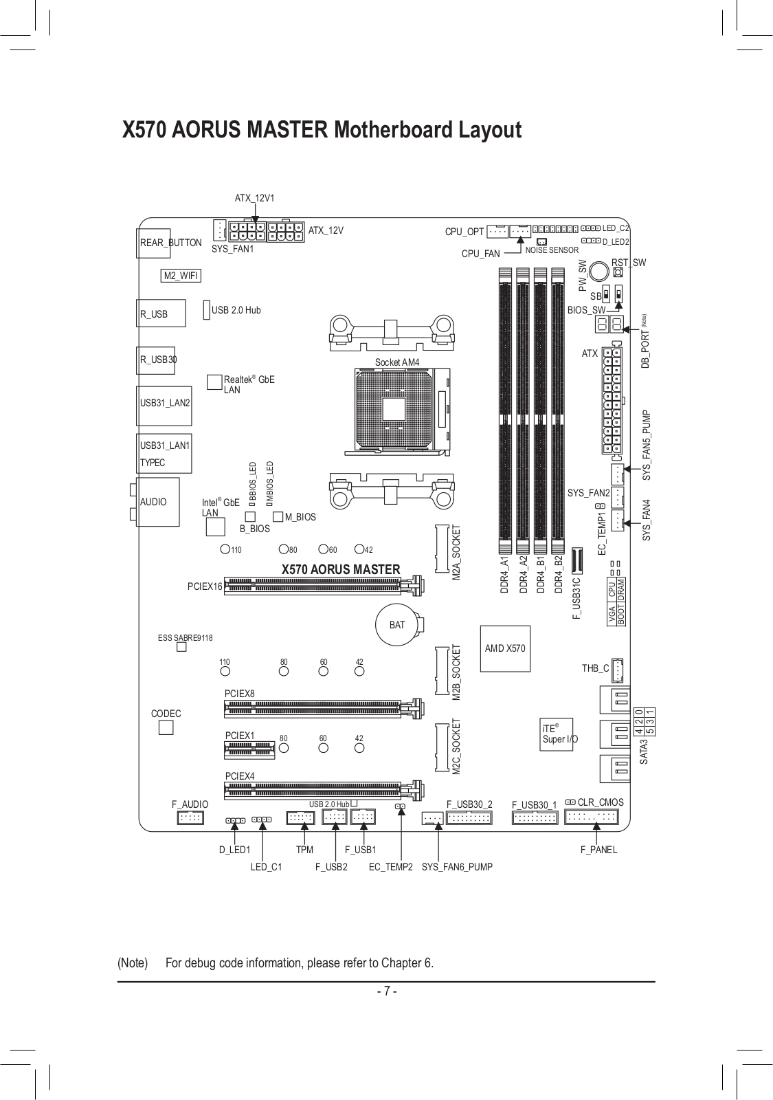

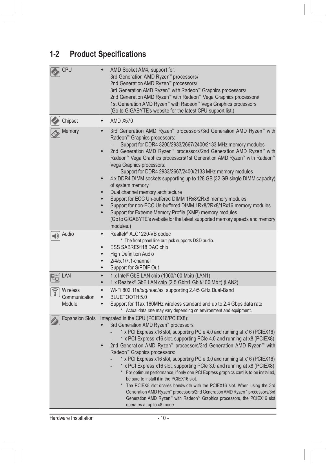
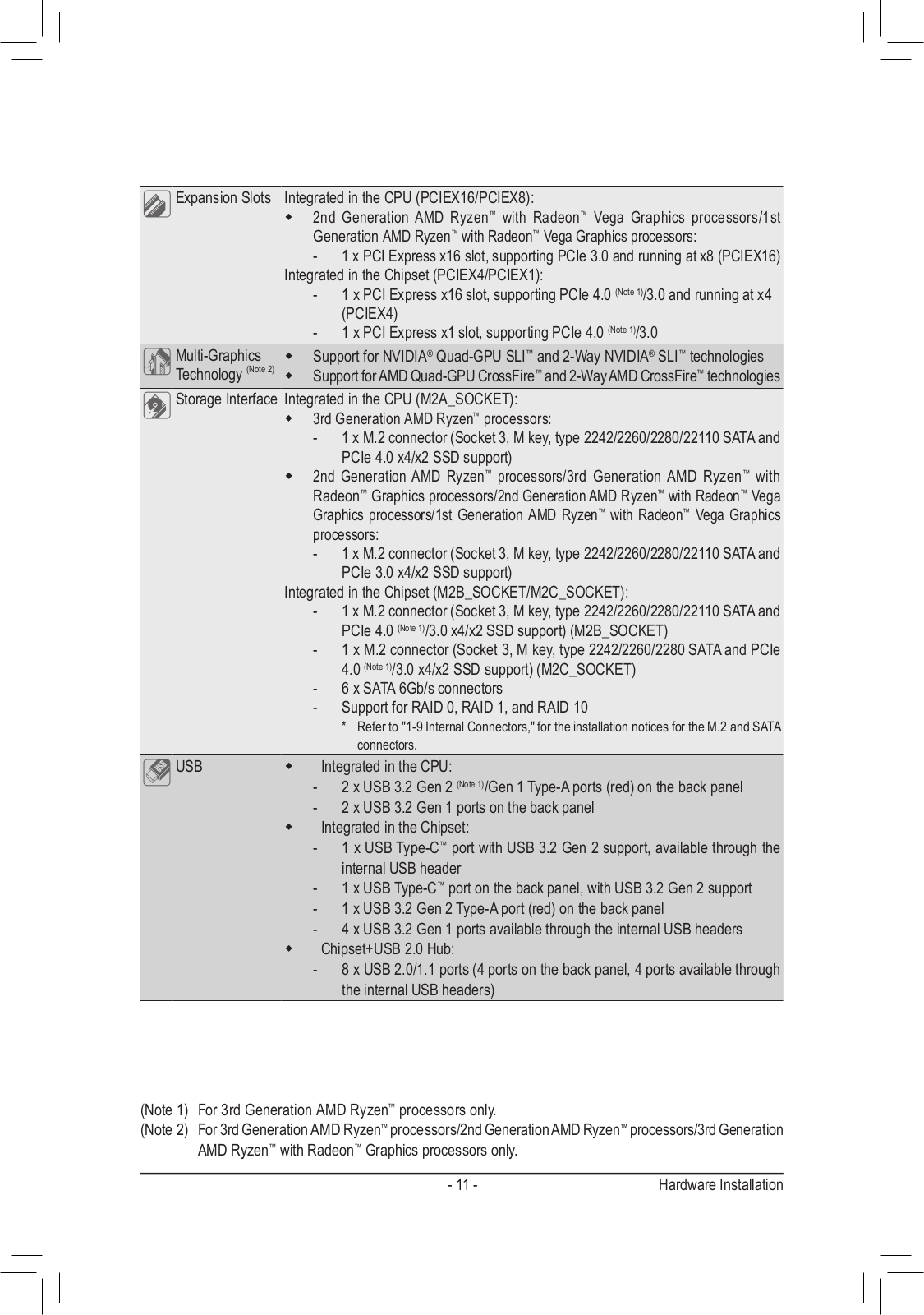
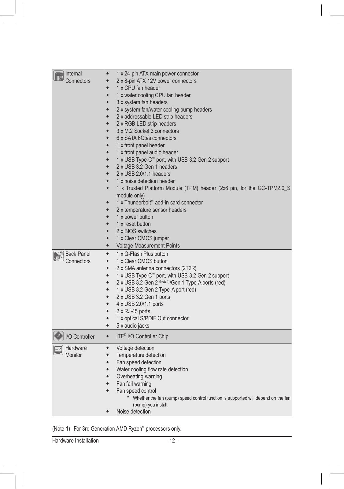
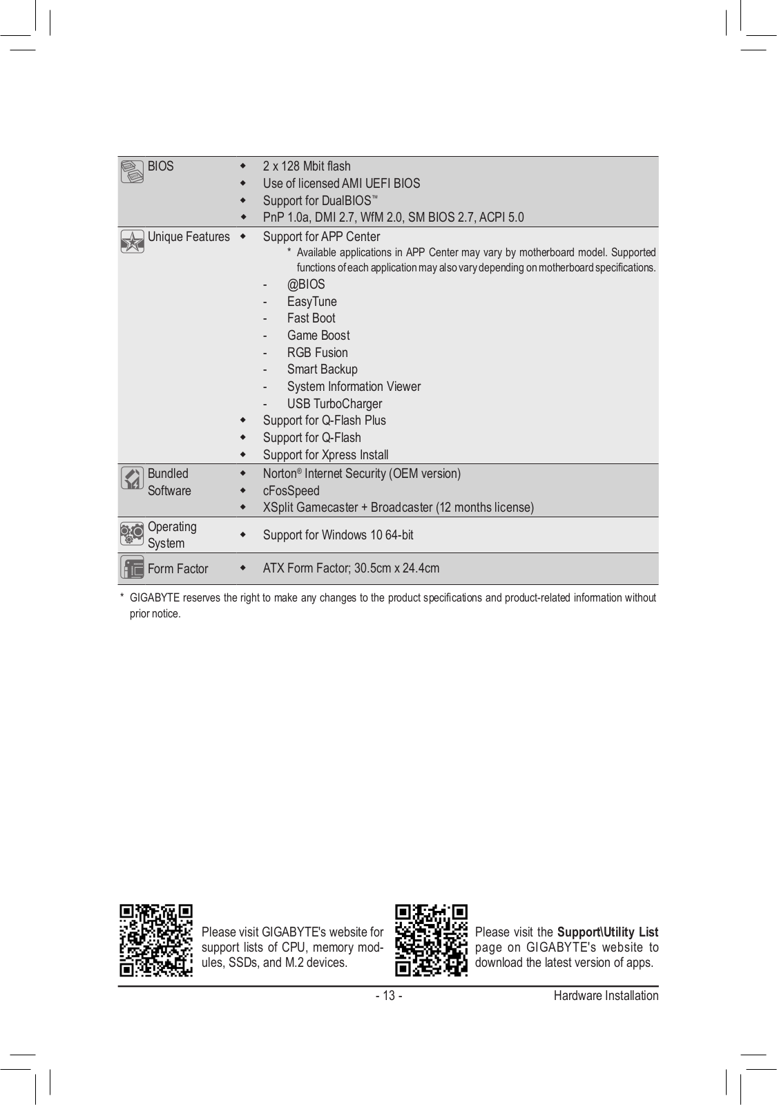
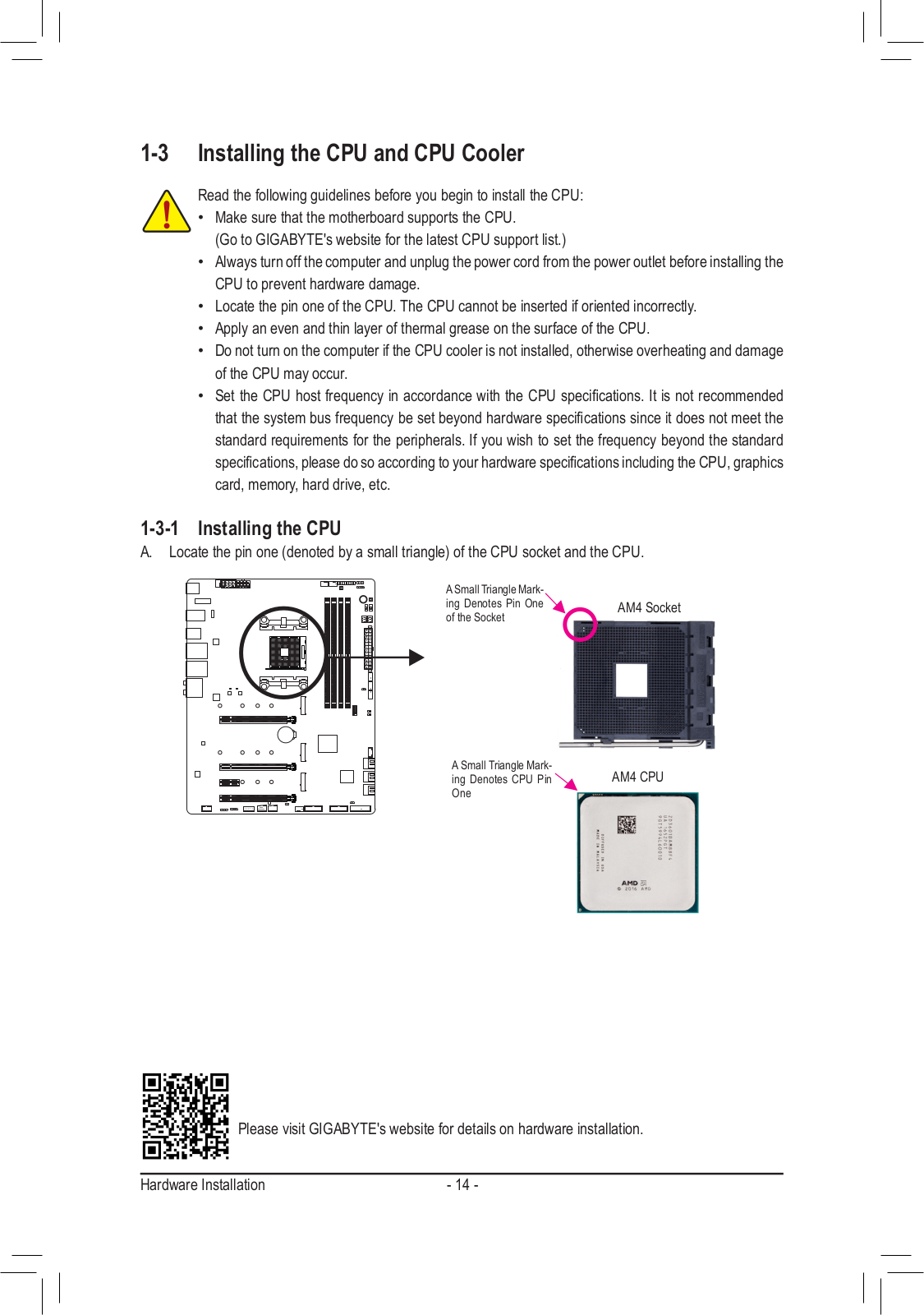

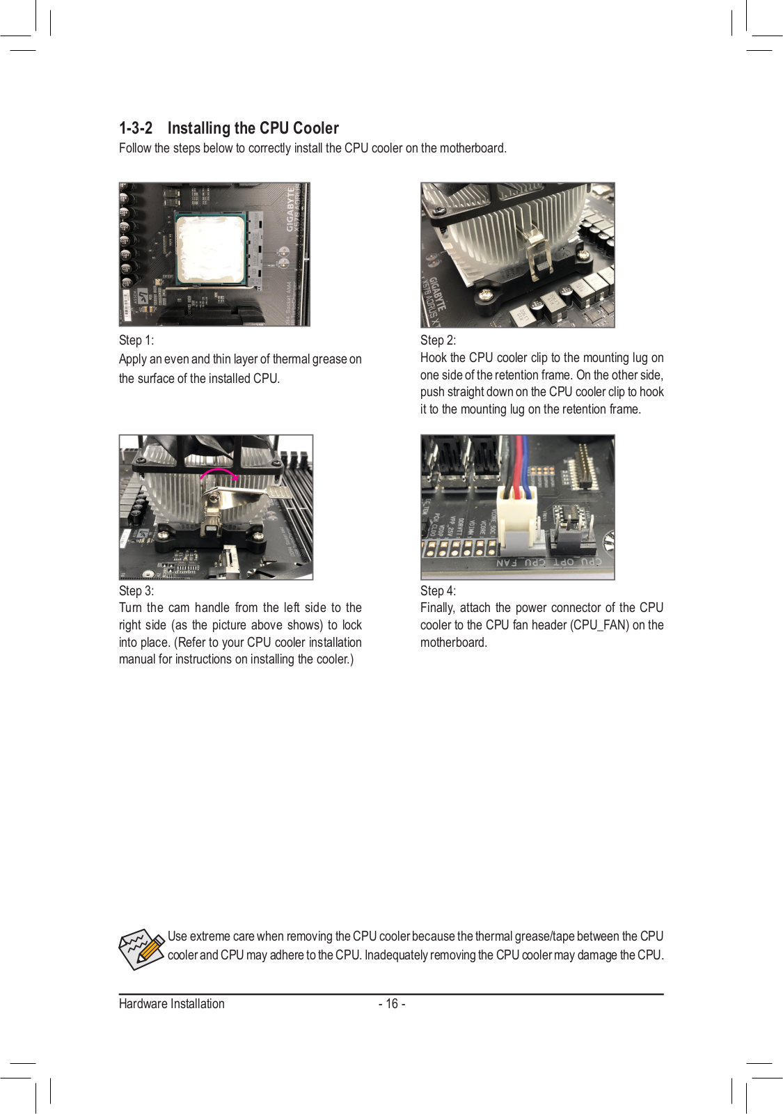
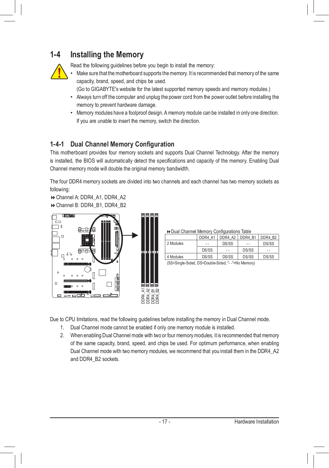
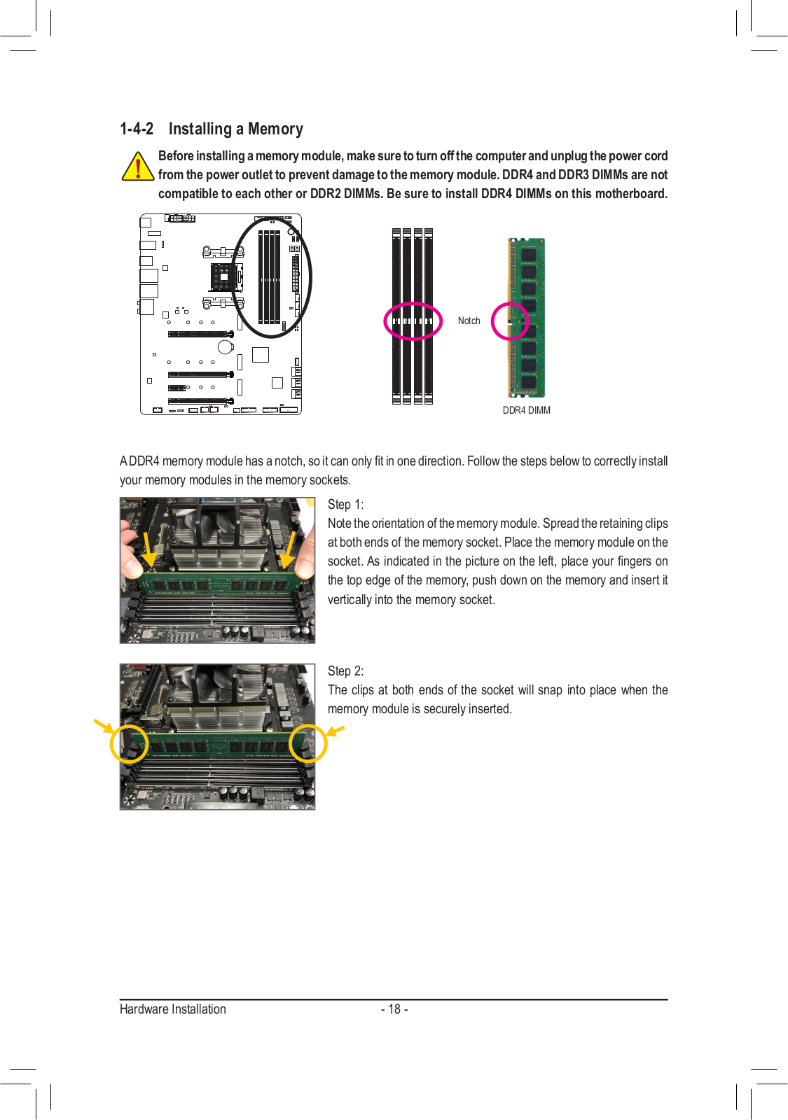
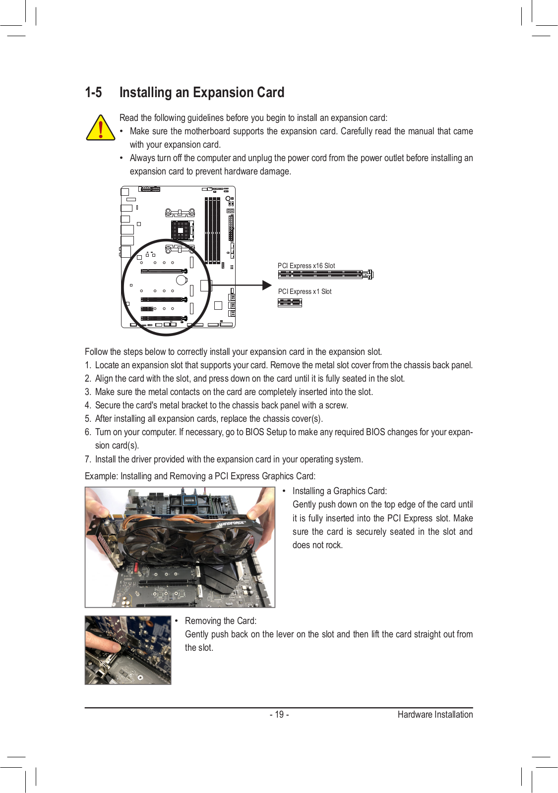
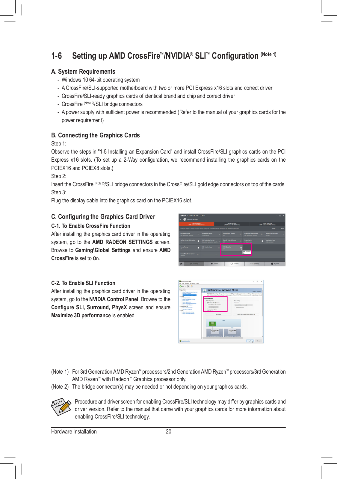
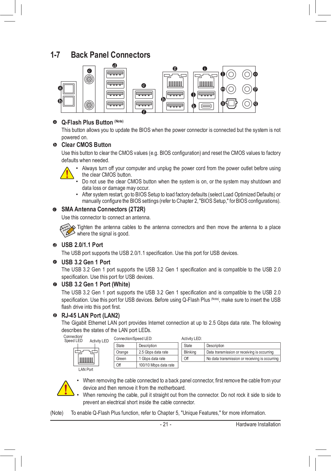
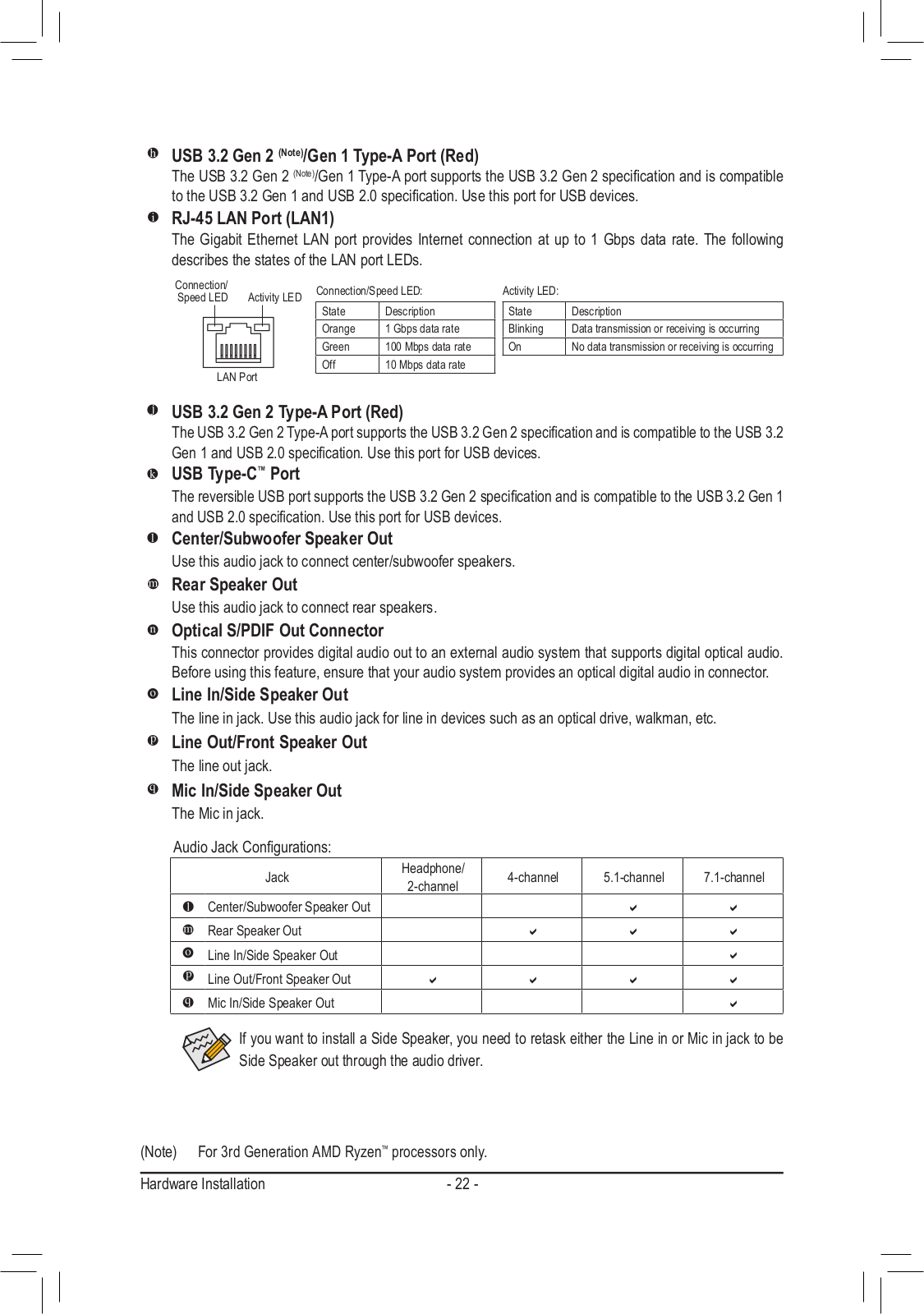
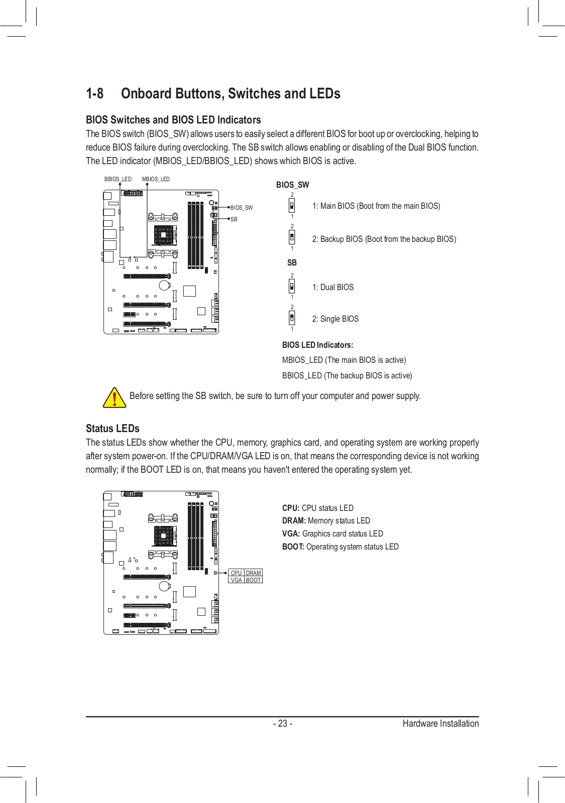
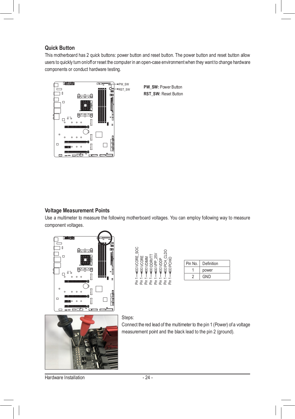

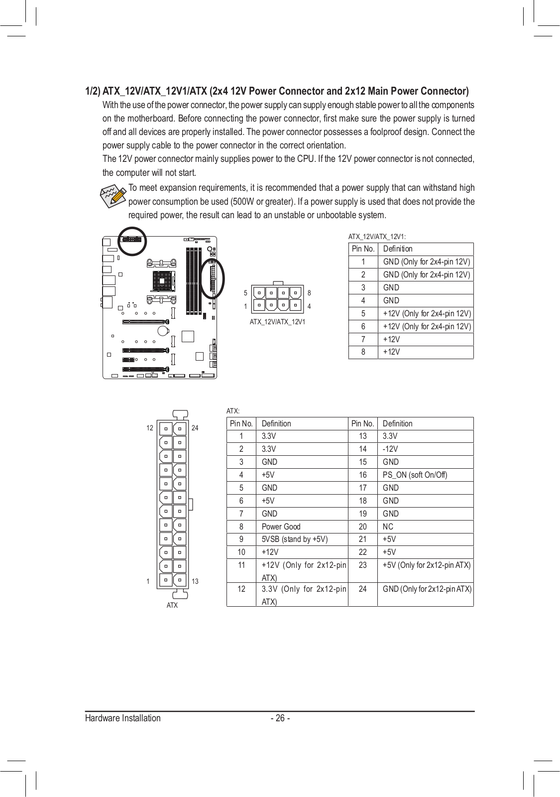
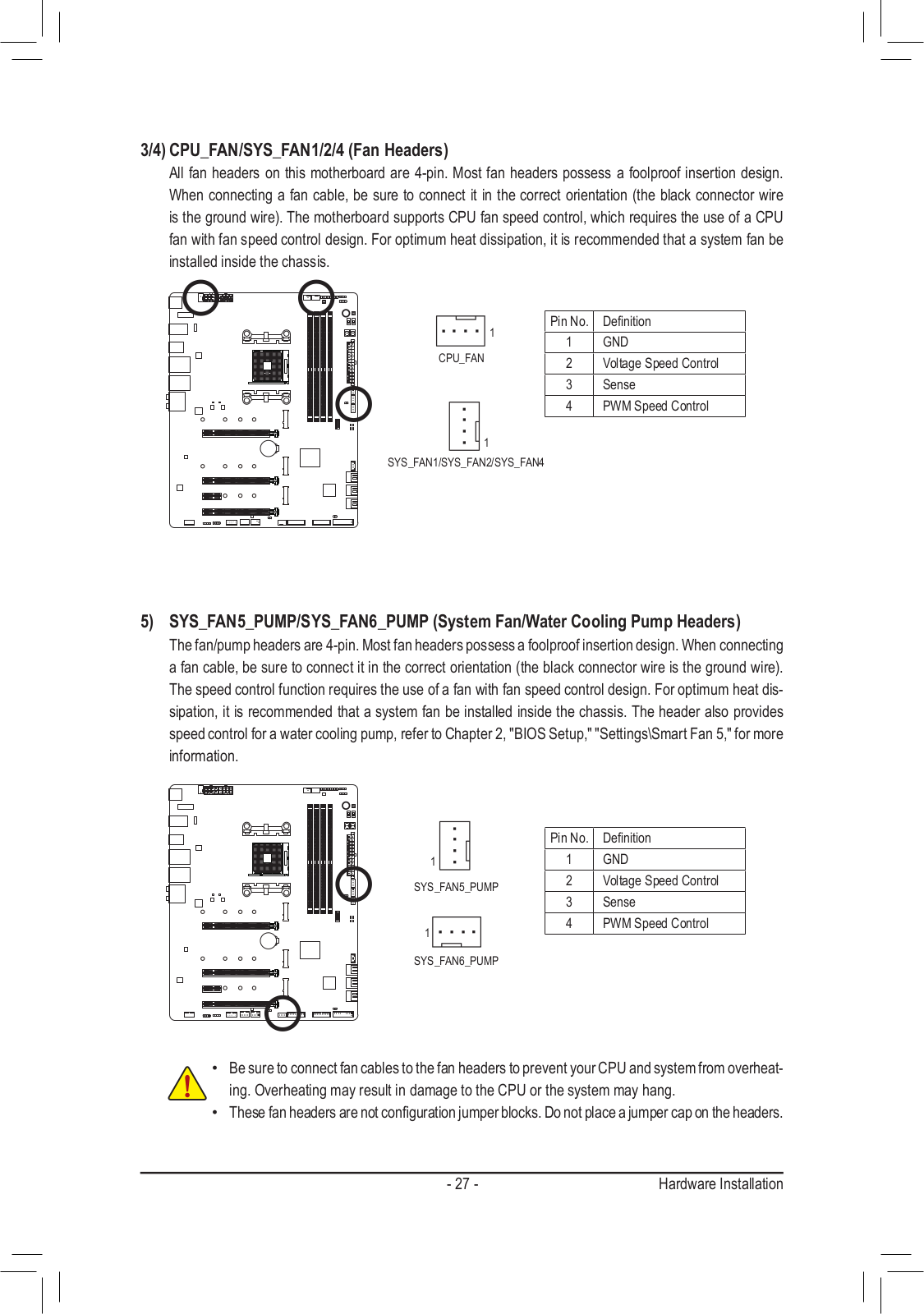
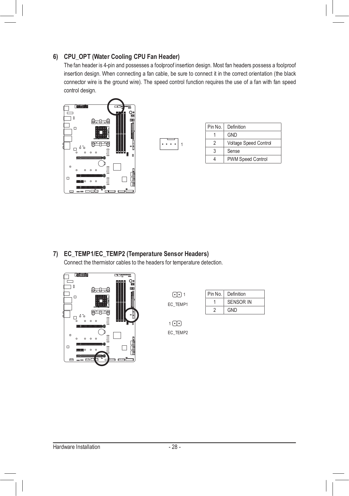
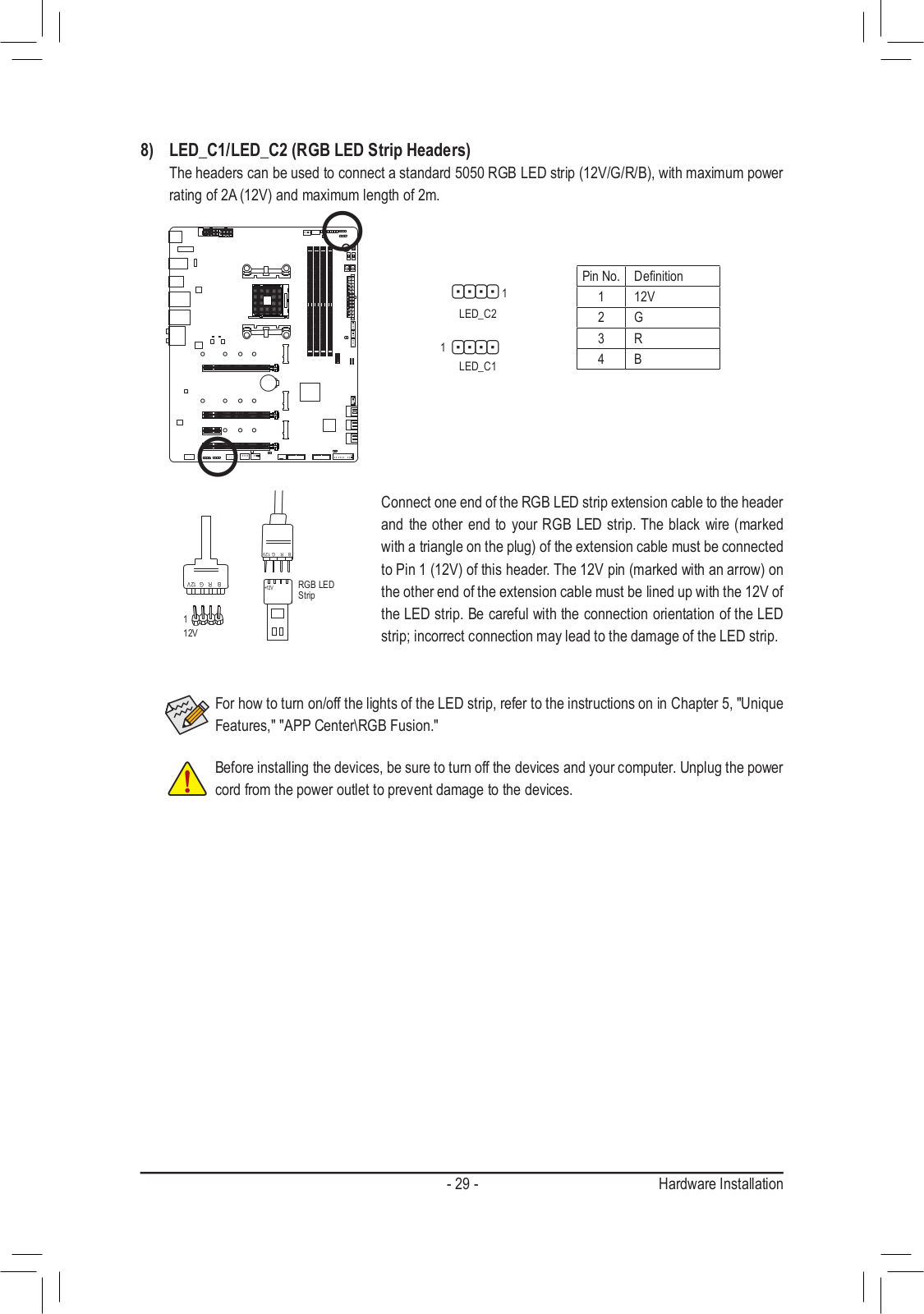
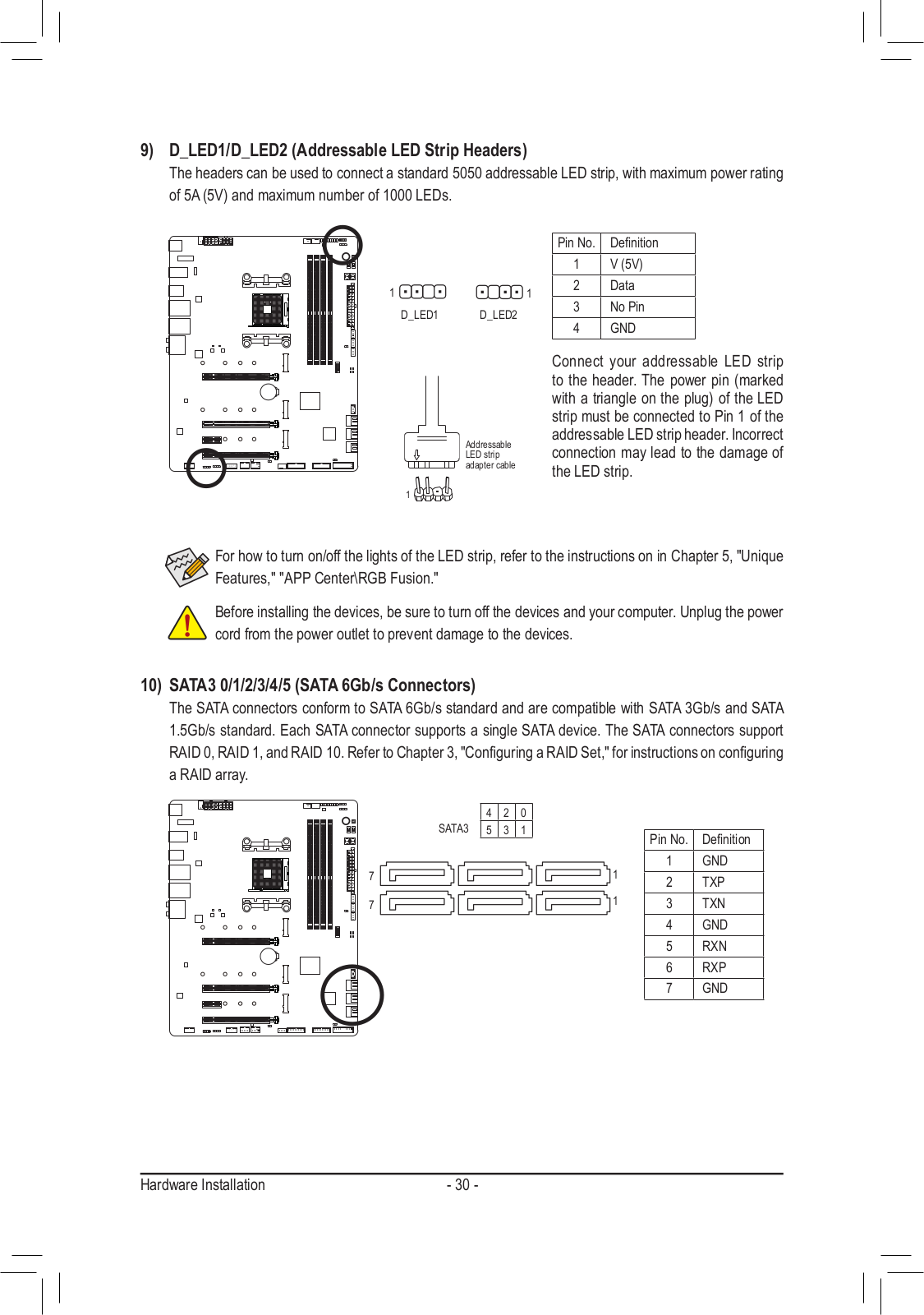
Loading…
+ 74 hidden pages
You need points to download manuals.
1 point = 1 manual.
You can buy points or you can get point for every manual you upload.
Buy points
Upload your manuals
|
Код: 124257 Извините, товара сейчас нет в наличии
Бесплатная доставка Извините, товара сейчас нет в наличии Сравнить Новости интернет-магазина «Лаукар»:23.04.2025 26.02.2025 17.02.2025 Дополнительная информация в категории Материнская плата:Таблица Авторизованных сервисных центров по брендам. Описание Инструкция Отзывы (0) В интернет-магазине бытовой техники «Лаукар» Вы можете скачать инструкцию к товару Материнская плата GIGABYTE X570 AORUS MASTER (rev. 1.0) совершенно бесплатно. Все инструкции, представленные на сайте интернет-магазина бытовой техники «Лаукар», предоставляются производителем товара. Для того чтобы скачать инструкцию, Вам необходимо нажать на ссылку «скачать инструкцию», расположенную ниже, а в случае, если ссылки нет, Скачать инструкцию Смотреть инструкцию 
Фирма-производитель оставляет за собой право на внесение изменений в конструкцию, дизайн и комплектацию товара: Материнская плата GIGABYTE X570 AORUS MASTER (rev. 1.0). Пожалуйста, сверяйте информацию о товаре с информацией на |
Сегодня мы отправляемся в мир новейшего чипсета AMD X570, это Gigabyte X570 Aorus Master. Master, как правило, является второй ступенью в верхней части стека, когда речь идет о материнских платах GIGABYTE, и сегодня мы рассматриваем очень интересную материнскую плату.
Общие характеристики
Новый чипсет и платформа AMD X570 предлагают все PCI-E 4.0, что вдвое больше скорости PCI-E 3.0, и это первая платформа с новым стандартом. AMD опередила платформу Intel серии Z300, представив интегрированный 10 Гбит / с USB на чипсете, и теперь они сделали это снова с PCI-E 4.0.
В настоящее время различия будут видны в основном с твердотельными накопителями PCI-E 4.0 M.2, но, со временем, мы увидим, что больше устройств получат преимущества. Давайте посмотрим, что нам предлагает эта материнская плата.
- X570 Aorus Master имеет:
- три слота PCI-E 4.0 M.2;
- 2.5G NIC, 2.4G WIFI контроллер;
- Intel Gbit NIC;
- Память 10 Гбит / с USB и высококачественный звук.
X570 Aorus Master стоит около 360 долларов.
Упаковка
Коробка и упаковка очень похожи на другие материнские платы GIGABYTE Aorus. Упаковка очень хорошо сделана и для этой модели. Комплект поставки включает четыре SATA6Gb / s, антенну WIFI, удлинительный кабель RGB LED, кабель RGB, кабель обнаружения dB, два термозонда, значок корпуса, G-разъем, две кабельные стяжки Aorus Velcro.
GIGABYTE вставил семь разъемов для подключения вентиляторов, и все они могут работать как в режиме постоянного тока, так и в режиме ШИМ. Все разъемы предлагают до 2А тока.
Существует также новый разъем для подключения микрофона, используемый в качестве измерителя dB, и для контроля уровня шума в вашей системе. Материнская плата также имеет заднюю панель, которая укрепляет ее и обеспечивает охлаждение задней части процессора VRM.
Задняя панель ввода-вывода оснащена двумя портами USB 3.0, тремя портами USB 3.1 (10 Гбит / с) типа A и одним типом C, кнопкой Clear CMOS, кнопкой Q-Flash Plus, антенной WIFI, 2.5G LAN, 1G LAN и позолотой 7.1. аудиовыходы с выходом S / PDIF.
Здесь мы находим расположение слотов PCI-E, первые два слота подключены к ЦП на x16 PCI-E 4.0 и работают на x16 / x0 или x8 / x8. Нижний слот x16 электрически x4 PCI-E 4.0 направлен на чипсет, и у нас также есть слот x1 PCI-E 4.0. Имеется три слота PCI-E x4 M.2, верхний из которых направлен на процессор и должен использоваться с любыми дисками PCI-E 4.0, средняя и нижняя области слотов направляют x4 PCI-E 4.0 на чипсет, но если использовать диск PCI-E M.2 в самом нижнем слоте — это отключит два порта SATA.
Все шесть портов SATA6Gb / s маршрутизируются на чипсет. Разъем USB типа 3,1 (10 Гбит / с) здесь направляется на чипсет. Мы также находим здесь новые светодиоды.
Оба внутренних разъема USB 3.0 направлены на чипсет. Мы также обнаружили два разъема USB 2.0, адресуемый светодиодный разъем RGB и разъем RGB в нижней части материнской платы.
Материнская плата имеет дисплей POST-кода, переключатель выбора BIOS, двойной выключатель BIOS, кнопку сброса, кнопку питания, разъем светодиода RGB, точки считывания напряжения и разъем светодиода RGB в верхнем правом углу материнской платы. Материнская плата также имеет два 8-контактных разъема питания процессора.
Радиаторы на этой материнской плате оптимизированы для работы с процессором VRM, все, от медных ребер до термопрокладок, было специально выбрано разработчиками.
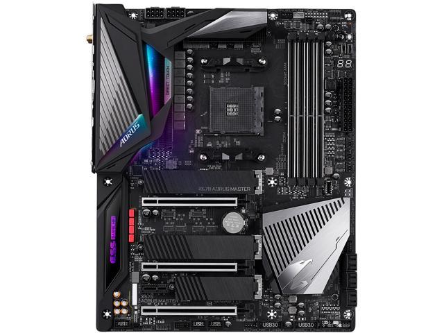
Анализ компановки
X570 Aorus Master показывает нам товары со снятыми радиаторами!
VRM имеет конфигурацию 12 + 2 фазы, и это настоящая 12 фаза, в которой не используются удвоители, новый цифровой ШИМ-контроллер Infineon поддерживает до 16 истинных фаз. GIGABYTE заявляет, что используя 12-фазный VRM по сравнению с другими, которые не используют истинные фазы, они получают эффективность 4%.
Хотя это может показаться не впечатляющим, разница между блоками питания 80 Plus Silver и 80 Plus Platinum фактически трудноразличима, так что это более значимые показатели, чем вы думаете. Оба VC CPU и SoC VRM используют International Rectifier 50A IR3556 PowIRstages и управляются цифровым ШИМ-контроллером Infineon XDPE132G5C.
Память VRM является однофазной, управляемой ШИМ-контроллером RT8120D и полевыми МОП-транзисторами PowerPAK в виде двух полевых МОП-транзисторов с низкой стороны.
Аудиооборудование включает Realtek ALC1220 с расширенной поддержкой dB на передней панели. GIGABYTE добавил ЦАП ESS SABRE ES9118 с SNR до 125 dB GIGABYTE также добавила аудио конденсатор золотой серии и несколько пленочных конденсаторов WIMA.
Обычная локальная сеть Gbit поставляется с сетевым адаптером Intel i211AT, а Realtek RTL8125AG обеспечивает до 2,5 Гбит LAN.
Есть четыре Pericom PI3EQX USB 3.1 (10 Гбит / с), три находятся на верхней части материнской платы, и один на задней панели. Имеется также контроллер Realtek типа C, RTS5441. Здесь же присутствует тактовый генератор IDT PCI-E 4.0, используемый для управления скоростью шины PCI-E 4.0.
Четыре перезаписывающих устройства PI3EQX16 PCI-E 4.0 перезаписывают x8 PCI-E 4.0 до того, как они перейдут к быстрым переключателям PI3DBS16 PCI-E 4.0, так что целостность сигнала может поддерживаться после прохождения быстрых переключателей x8 PCI-E 4.0.
Основным SuperIO является IT8688E, это основной SuperIO на материнской плате.
Концентратор GL850S USB 2.0 имеет четыре порта USB 2.0 на задней панели ввода-вывода. Здесь у нас есть два встроенных контроллера, они обеспечивают дополнительное управление вентилятором и такие функции, как монитор dB.
A = n ITE IT8297 используется для обеспечения управления и поддержки светодиодов RGB. GIGABYTE предлагает резервные 128-битные ПЗУ BIOS, один из которых можно заменить. Чип BIOS для восстановления USB — это 504N, тот же самый чип, который мы видим на материнской плате MSI, GIGABYTE впервые его использует.
Эти два VRM обеспечивают регулирование напряжения для внутреннего разъема USB 3.0 на передней панели, который поддерживает Quick Charge 3.0.
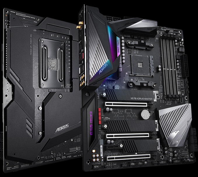
BIOS
BIOS UEFI был обновлен для материнских плат GIGABYTE X570. Новый UEFI не только улучшил управление мышью и его расположение, но теперь он будет отображаться в формате 1080P. Новый UEFI имеет измененную структуру, чтобы сделать его более компактным и сократить количество слоев меню, которые вам нужно пройти, чтобы найти настройки. Нам нравится редизайн, и у нас все еще есть управление вентиляторами на основе графического интерфейса и меню AMD CBS.
Программное обеспечение
Программное обеспечение включает в себя APP Center, @BIOS, AutoGreen, Cloud Station, EasyTune, Fast Boot, Game Boost, RGB Fusion, Smart Backup, Smart Keyboard, Smart Survey, Просмотр информации о системе, USB Blocker и USB TurboCharger.
Технические характеристики тестовой системы
Задняя часть материнской платы загорается, но не так, как предыдущие Aorus Masters; светодиоды RGB менее выражены.
Разгон
Новые процессоры не разгоняются как сумасшедшие в эфире; фактически, PBOC может быть столь же эффективным для случаев смешанного использования.
Тем не менее, память и тактовые частоты FCLK можно изменить, поэтому мы используем набор с частотой 3600 МГц и видим, как высоко работают все ядра. Мы стремимся к 4,3 ГГц с тактовой частотой памяти 3600 МГц, и в этом случае она работала нормально при 1,42 В, так как именно здесь мы достигли температурного предела.
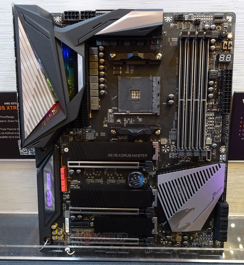
Производительность
ADVERTISEMENT одинакова на обеих этих материнских платах, мы не можем найти явного победителя, но мы ожидаем этого, поскольку ядро AMD для UEFI является закрытым анклавом. Мы увидим, изменится ли это, когда будем тестировать больше материнских плат
Производительность хранилища и сети хорошая. Мы ожидали большего от накопителя в отношении последовательного чтения, и мы рассмотрим наши результаты, поскольку основная проблема этих накопителей заключается в охлаждении.
Аудио RMAA 5.5
Тестирование звука на слух: отлично, ЦАП и ALC1220 делают свою работу. Есть пять оценок для аудио:
1. Проблемы.
2. Хорошо.
3. Приемлемо.
4. Очень хорошо.
5. Отлично.
Потребляемая мощность
Оценить потребляемую мощность должным образом не удалось. Нам нужно больше образцов, чтобы сделать какие-то окончательные выводы.
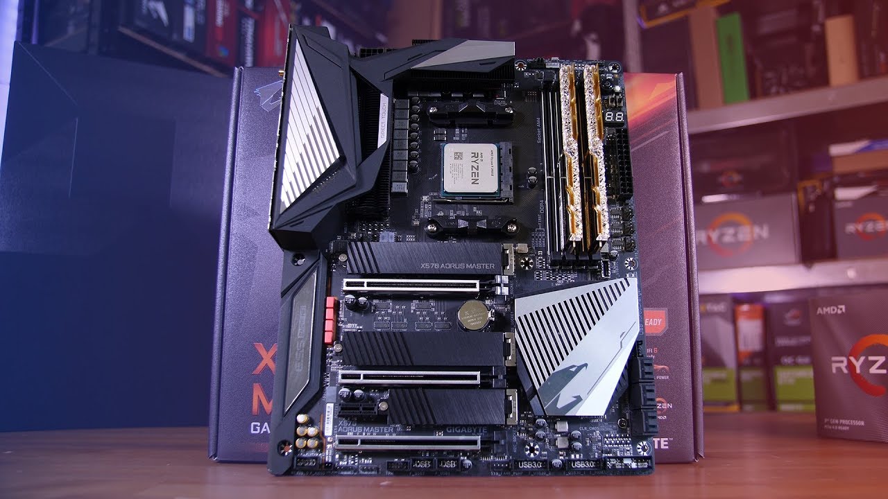
Что нового?
Превосходный VRM : VRM, который есть у нас на этой высококачественной материнской плате X570, является прямым 12 + 2-фазным VRM с использованием 50A PowIRstages и новейшей технологией PWM от Infineon. Это одна из лучших VRM, которые мы видели до сих пор, и она не должна создавать проблем при максимальной загрузке вашего процессора.
Три слота PCI-E 4.0 M.2 : верхний слот M.2 подключен непосредственно к процессору PCI-E 4.0 x4 и является лучшим для использования с диском PCI-E 4.0 M.2. Два других также PCI-E 4.0 x4, и они подключены к чипсету.
Отличная работа в сети и аудио : включенный WIFI 6 Wireless AX поддерживает не только более старый стандарт беспроводной сети переменного тока до 1,733 Гбит / с, но и новый стандарт Wireless AX 2,4 Гбит / с. Локальная сеть Realtek 2.5G — это отличное решение для приведения проводной сети в соответствие с Wireless AX, а включение Intel i211AT порадует многих. Дополнительные улучшения звука, такие как ЦАП ESS ES9118 и высококачественные конденсаторы, являются отличным дополнением.
Недостатки
Цена: Все высококлассные компоненты стоят больших денег, но, как и многие материнские платы X570 стоит слишком дорого. При цене $ 360 он почти такой же дорогой, как и некоторые высокопроизводительные процессоры AMD для этой платформы, и, хотя в этом ценовом диапазоне существует конкуренция, большинство других материнских плат дешевле, чем X570.
Выводы
X570 Aorus Master дорогой, но это в основном связано с природой платформы X570. Для реализации PCI-E 4.0 и всех USB 3.1 (10 Гбит / с) поставщики должны включать в себя много дополнительного оборудования.
GIGABYTE также добавил более дорогие контроллеры WIFI и LAN, очень хороший и дорогой VRM, который отлично справился с эстетикой. Разгонные функции являются хорошим дополнением, как и все разъемы для вентиляторов и новая функция контроля уровня dB. В целом, мы очень впечатлены этой материнской платой и даже новой структурой BIOS, и нам действительно на сильно пришлась по душе.