

To reduce the impacts on global warming, the packaging materials of this product
are recyclable and reusable. GIGABYTE works with you to protect the environment.
For more product details, please visit GIGABYTE’s website.
B550 AORUS ELITE V2B550 AORUS ELITE AX V2
B550 AORUS ELITE AX V2
B550 AORUS ELITE V2
User’s Manual
Rev. 1001
12ME-B55AEW2-1001R
— 2 —
Copyright
© 2020 GIGA-BYTE TECHNOLOGY CO., LTD. All rights reserved.
The trademarks mentioned in this manual are legally registered to their respective owners.
Disclaimer
Information in this manual is protected by copyright laws and is the property of GIGABYTE.
Changes to the specications and features in this manual may be made by GIGABYTE without prior
notice. No part of this manual may be reproduced, copied, translated, transmitted, or published in
any form or by any means without GIGABYTE’s prior written permission.
In order to assist in the use of this product, carefully read the User’s Manual.
For product-related information, check on our website at: https://www.gigabyte.com
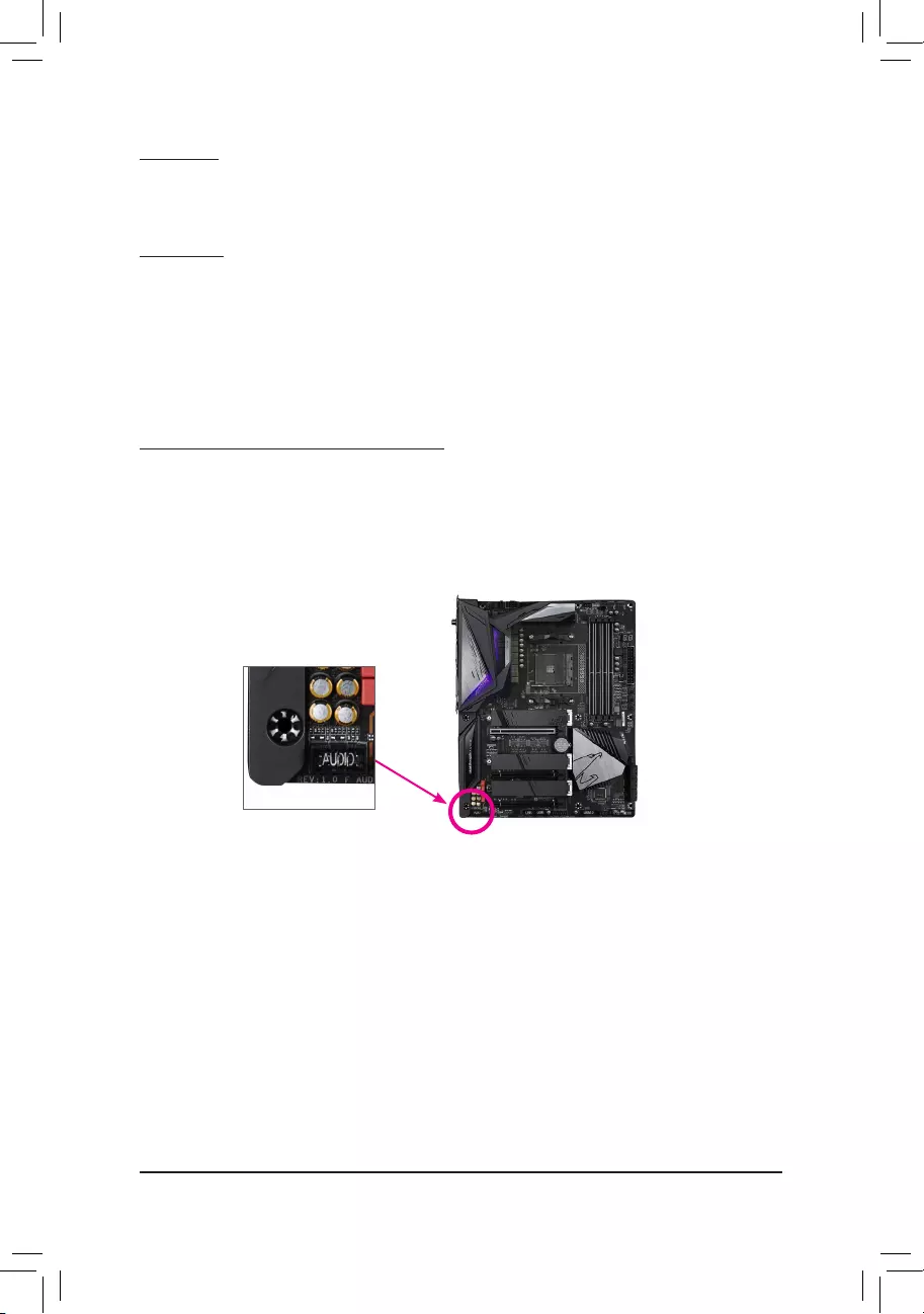
Identifying Your Motherboard Revision
The revision number on your motherboard looks like this: «REV: X.X.» For example, «REV: 1.0″
means the revision of the motherboard is 1.0. Check your motherboard revision before updating
motherboard BIOS, drivers, or when looking for technical information.
Example:

— 3 —
Table of Contents
B550 AORUS ELITE (AX) V2 Motherboard Layout ………………………………………………… 4
Chapter 1 Hardware Installation ………………………………………………………………………….5
1-1 Installation Precautions ………………………………………………………………………… 5
1-2 Product Specications ………………………………………………………………………….. 6
1-3 Installing the CPU ……………………………………………………………………………….. 9
1-4 Installing the Memory …………………………………………………………………………… 9
1-5 Installing an Expansion Card ………………………………………………………………. 10
1-6 Back Panel Connectors ………………………………………………………………………. 10
1-7 Internal Connectors ……………………………………………………………………………. 13
Chapter 2 BIOS Setup ……………………………………………………………………………………..21
2-1 Startup Screen ………………………………………………………………………………….. 21
2-2 The Main Menu …………………………………………………………………………………. 22
2-3 Favorites (F11) ………………………………………………………………………………….. 23
2-4 Tweaker ……………………………………………………………………………………………. 24
2-5 Settings ……………………………………………………………………………………………. 27
2-6 System Info. ……………………………………………………………………………………… 32
2-7 Boot …………………………………………………………………………………………………. 33
2-8 Save & Exit ……………………………………………………………………………………….. 36
Chapter 3 Appendix …………………………………………………………………………………………37
3-1 Conguring a RAID Set ………………………………………………………………………. 37
3-2 Drivers Installation ……………………………………………………………………………… 39
Regulatory Notices ………………………………………………………………………………………. 40
Contact Us …………………………………………………………………………………………………. 44
— 4 —
B550 AORUS ELITE (AX) V2 Motherboard Layout
Box Contents
5B550 AORUS ELITE AX V2 or B550 AORUS ELITE V2 motherboard
5Motherboard driver disc 5One G Connector
5User’s Manual 5One antenna (Note)
5Two SATA cables
* The box contents above are for reference only and the actual items shall depend on the product package you obtain.
The box contents are subject to change without notice.
M2_WIFI (Note)
(Note) Only for the B550 AORUS ELITE AX V2.
Socket AM4
AMD B550
USB20 CPU_FAN
ATX_12V
ATX
F_AUDIO
AUDIO
BAT
F_PANEL
PCIEX1_2
CLR_CMOS
CODEC
M_BIOS
PCIEX16
B550 AORUS ELITE (AX) V2
iTE
®
Super I/O
F_USB1
LED_C1
TPM
F_U32
M2B_SB
42
6080
110
CPU_OPT
SYS_FAN1
F_USB2SYS_FAN3
D_LED1
D_LED2 LED_C2
SYS_FAN2
DDR4_A1
DDR4_A2
DDR4_B1
DDR4_B2
SATA3
2
3
PCIEX1_1
PCIEX2
M2A_CPU
42
6080
110
LED_CPU
Realtek®
2.5GbE LAN
U32_LAN
U32G2
QFLASH_PLUS
QFLED
DP_HDMI
U32
USB 2.0 Hub
1 0
SATA3
F_U32C

Chapter 1 Hardware Installation
1-1 Installation Precautions
The motherboard contains numerous delicate electronic circuits and components which can become
damaged as a result of electrostatic discharge (ESD). Prior to installation, carefully read the user’s
manual and follow these procedures:
•Prior to installation, make sure the chassis is suitable for the motherboard.
•Prior to installation, do not remove or break motherboard S/N (Serial Number) sticker or
warranty sticker provided by your dealer. These stickers are required for warranty validation.
•Always remove the AC power by unplugging the power cord from the power outlet before
installing or removing the motherboard or other hardware components.
•When connecting hardware components to the internal connectors on the motherboard, make
sure they are connected tightly and securely.
•When handling the motherboard, avoid touching any metal leads or connectors.
•It is best to wear an electrostatic discharge (ESD) wrist strap when handling electronic
components such as a motherboard, CPU or memory. If you do not have an ESD wrist strap,
keep your hands dry and rst touch a metal object to eliminate static electricity.
•Prior to installing the motherboard, please have it on top of an antistatic pad or within an
electrostatic shielding container.
•Before connecting or unplugging the power supply cable from the motherboard, make sure
the power supply has been turned off.
•Before turning on the power, make sure the power supply voltage has been set according to
the local voltage standard.
•Before using the product, please verify that all cables and power connectors of your hardware
components are connected.
•To prevent damage to the motherboard, do not allow screws to come in contact with the
motherboard circuit or its components.
•Make sure there are no leftover screws or metal components placed on the motherboard or
within the computer casing.
•Do not place the computer system on an uneven surface.
•Do not place the computer system in a high-temperature or wet environment.
•Turning on the computer power during the installation process can lead to damage to system
components as well as physical harm to the user.
•If you are uncertain about any installation steps or have a problem related to the use of the
product, please consult a certied computer technician.
•If you use an adapter, extension power cable, or power strip, ensure to consult with its installation
and/or grounding instructions.
— 5 —
1-2 ProductSpecications
CPU AMD Socket AM4, support for:
3rd Generation AMD Ryzen™ processors/
3rd Generation AMD Ryzen™ with Radeon™ Graphics processors
(Go to GIGABYTE’s website for the latest CPU support list.)
Chipset AMD B550
Memory 4 x DDR4 DIMM sockets supporting up to 128 GB (32 GB single DIMM capacity)
of system memory
Support for DDR4 3200/2933/2667/2400/2133 MHz memory modules
Dual channel memory architecture
Support for ECC Un-buffered DIMM 1Rx8/2Rx8 memory modules
Support for non-ECC Un-buffered DIMM 1Rx8/2Rx8/1Rx16 memory modules
Support for Extreme Memory Prole (XMP) memory modules
(Go to GIGABYTE’s website for the latest supported memory speeds and memory
modules.)
Onboard
Graphics
Integrated in the 3rd Generation AMD Ryzen™ with Radeon™ Graphics processors:
— 1 x DisplayPort, supporting a maximum resolution of 5120x2880@60 Hz
* Support for DisplayPort 1.4 version, HDCP 2.3, and HDR.
— 1 x HDMI port, supporting a maximum resolution of 4096×2160@60 Hz
* Support for HDMI 2.1 version, HDCP 2.3, and HDR.
Maximum shared memory of 16 GB
Audio Realtek® ALC1200 codec
High Denition Audio
2/4/5.1/7.1-channel
Support for S/PDIF Out
LAN Realtek® 2.5GbE LAN chip (2.5 Gbit/1 Gbit/100 Mbit)
Wireless
Communication
Module (Note)
Intel® Wi-Fi 6 AX200
— WIFI a, b, g, n, ac with wave 2 features, ax, supporting 2.4/5 GHz Dual-Band
— BLUETOOTH 5
— Support for 11ax 160MHz wireless standard and up to 2.4 Gbps data rate
* Actual data rate may vary depending on environment and equipment.
Expansion Slots 1 x PCI Express x16 slot (PCIEX16), integrated in the CPU:
— 3rd Generation AMD Ryzen™ processors support PCIe 4.0 x16 mode
— 3rd Generation AMD Ryzen™ with Radeon™ Graphics processors support
PCIe 3.0 x16 mode
* For optimum performance, if only one PCI Express graphics card is to be installed,
be sure to install it in the PCIEX16 slot.
1 x PCI Express x16 slot (PCIEX2), integrated in the Chipset:
— Supporting PCIe 3.0 x2 mode
1 x PCI Express x16 slot (PCIEX1_2), integrated in the Chipset:
— Supporting PCIe 3.0 x1 mode
1 x PCI Express x1 slot (PCIEX1_1), integrated in the Chipset:
— Supporting PCIe 3.0 x1 mode
— 6 —
(Note) Only for the B550 AORUS ELITE AX V2.
Storage Interface 1 x M.2 connector (M2A_CPU), integrated in the CPU, supporting Socket 3,
M key, type 2242/2260/2280/22110 SSDs:
—
3rd Generation AMD Ryzen™ processors support SATA and PCIe 4.0 x4/x2 SSDs
— 3rd Generation AMD Ryzen™ with Radeon™ Graphics processors support
SATA and PCIe 3.0 x4/x2 SSDs
1 x M.2 connector (M2B_SB), integrated in the Chipset, supporting Socket 3,
M key, type 2242/2260/2280/22110 SSDs:
— Supporting SATA and PCIe 3.0 x4/x2 SSDs
4 x SATA 6Gb/s connectors, integrated in the Chipset:
— Support for RAID 0, RAID 1, and RAID 10
USB CPU:
— 2 x USB 3.2 Gen 2 Type-A ports (red) on the back panel
— 2 x USB 3.2 Gen 1 ports on the back panel
Chipset:
— 1 x USB Type-C™ port with USB 3.2 Gen 1 support, available through the
internal USB header
— 1 x USB 3.2 Gen 1 port on the back panel
— 2 x USB 3.2 Gen 1 ports available through the internal USB header
— 2 x USB 2.0/1.1 ports on the back panel
Chipset+USB 2.0 Hub:
— 4 x USB 2.0/1.1 ports available through the internal USB headers
Internal
Connectors
1 x 24-pin ATX main power connector
1 x 8-pin ATX 12V power connector
2 x M.2 Socket 3 connectors
4 x SATA 6Gb/s connectors
1 x CPU fan header
1 x water cooling CPU fan header
3 x system fan headers
1 x CPU cooler LED strip/RGB LED strip header
2 x addressable LED strip headers
2 x RGB LED strip headers
1 x front panel header
1 x front panel audio header
1 x USB Type-C™ port, with USB 3.2 Gen 1 support
1 x USB 3.2 Gen 1 header
2 x USB 2.0/1.1 headers
1 x Trusted Platform Module (TPM) header (2×6 pin, for the GC-TPM2.0_S module only)
1 x Clear CMOS jumper
Back Panel
Connectors
1 x DisplayPort
1 x HDMI port
2 x SMA antenna connectors (2T2R) (Note)
2 x USB 3.2 Gen 2 Type-A ports (red)
3 x USB 3.2 Gen 1 ports
2 x USB 2.0/1.1 ports
1 x Q-Flash Plus button
1 x RJ-45 port
1 x optical S/PDIF Out connector
5 x audio jacks
— 7 —
(Note) Only for the B550 AORUS ELITE AX V2.
I/O Controller iTE® I/O Controller Chip
Hardware
Monitor
Voltage detection
Temperature detection
Fan speed detection
Water cooling ow rate detection
Overheating warning
Fan fail warning
Fan speed control
* Whether the fan speed control function is supported will depend on the fan you install.
BIOS 1 x 256 Mbit ash
Use of licensed AMI UEFI BIOS
PnP 1.0a, DMI 2.7, WfM 2.0, SM BIOS 2.7, ACPI 5.0
Unique Features Support for APP Center
* Available applications in APP Center may vary by motherboard model. Supported
functions of each application may also vary depending on motherboard specications.
— @BIOS
— EasyTune
— Fast Boot
— Game Boost
— ON/OFF Charge
— RGB Fusion
— Smart Backup
— System Information Viewer
Support for Q-Flash Plus
Support for Q-Flash
Support for Xpress Install
Bundled
Software
Norton® Internet Security (OEM version)
Realtek® 8125 Gaming LAN Bandwidth Control Utility
Operating
System Support for Windows 10 64-bit
Form Factor ATX Form Factor; 30.5cm x 24.4cm
* GIGABYTE reserves the right to make any changes to the product specications and product-related information without
prior notice.
Please visit GIGABYTE’s website for support lists of CPU, memory
modules, SSDs, and M.2 devices.
Please visit the Support\Utility List page on GIGABYTE’s website to
download the latest version of apps.
— 8 —
B550 AORUS ELITE V2B550 AORUS ELITE AX V2
Please visit GIGABYTE’s website for details on hardware installation.
DualChannelMemoryConguration
This motherboard provides four memory sockets and supports Dual Channel Technology. After the memory
is installed, the BIOS will automatically detect the specications and capacity of the memory. Enabling Dual
Channel memory mode will double the original memory bandwidth.
The four memory sockets are divided into two channels and each channel has two memory sockets as following:
Channel A: DDR4_A1, DDR4_A2
Channel B: DDR4_B1, DDR4_B2
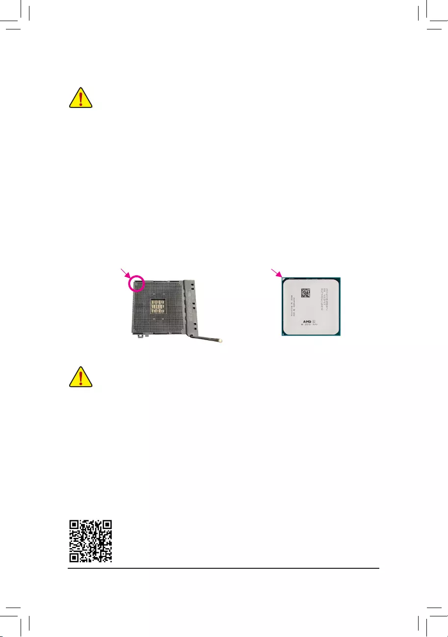
1-3 Installing the CPU
Read the following guidelines before you begin to install the CPU:
•Make sure that the motherboard supports the CPU.
(Go to GIGABYTE’s website for the latest CPU support list.)
•Always turn off the computer and unplug the power cord from the power outlet before installing the
CPU to prevent hardware damage.
•Locate the pin one of the CPU. The CPU cannot be inserted if oriented incorrectly.
•Apply an even and thin layer of thermal grease on the surface of the CPU.
•Do not turn on the computer if the CPU cooler is not installed, otherwise overheating and damage
of the CPU may occur.
•Set the CPU host frequency in accordance with the CPU specications. It is not recommended
that the system bus frequency be set beyond hardware specications since it does not meet the
standard requirements for the peripherals. If you wish to set the frequency beyond the standard
specications, please do so according to your hardware specications including the CPU, graphics
card, memory, hard drive, etc.
Installing the CPU
Completely lift up the CPU socket locking lever. Locate the pin one (denoted by a small triangle) of the CPU
socket and the CPU. Once the CPU is positioned into its socket, place one nger down on the middle of the
CPU, lowering the locking lever and latching it into the fully locked position.
Read the following guidelines before you begin to install the memory:
•Make sure that the motherboard supports the memory. It is recommended that memory of the same
capacity, brand, speed, and chips be used.
(Go to GIGABYTE’s website for the latest supported memory speeds and memory modules.)
•Always turn off the computer and unplug the power cord from the power outlet before installing the
memory to prevent hardware damage.
•Memory modules have a foolproof design. A memory module can be installed in only one direction.
If you are unable to insert the memory, switch the direction.
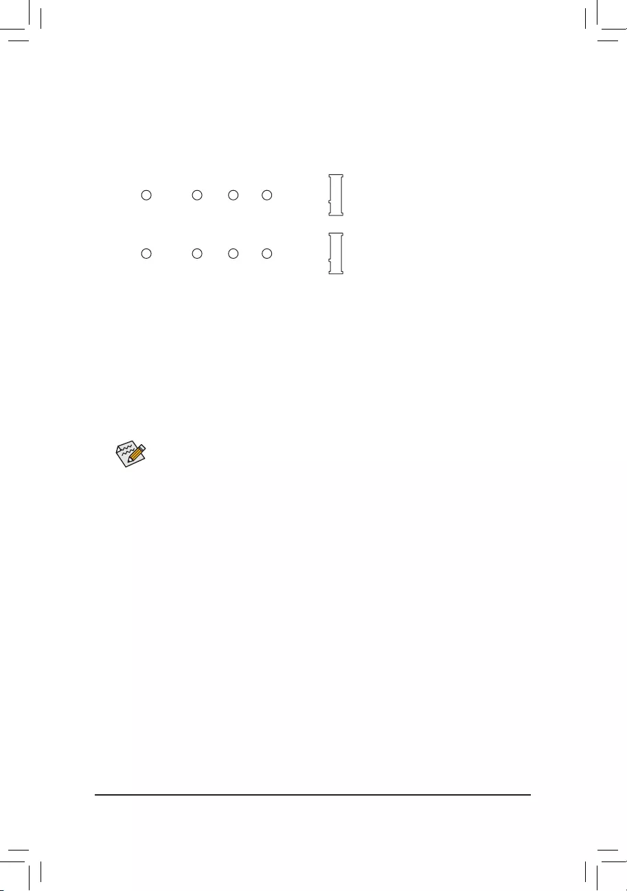
AM4 Socket
A Small Triangle
Marking Denotes Pin
One of the Socket AM4 CPU
A Small Triangle
Marking Denotes CPU
Pin One
1-4 Installing the Memory
— 9 —
Due to CPU limitations, read the following guidelines before installing the memory in Dual Channel mode.
1. Dual Channel mode cannot be enabled if only one memory module is installed.
2. When enabling Dual Channel mode with two or four memory modules, it is recommended that memory
of the same capacity, brand, speed, and chips be used.
1-5 Installing an Expansion Card
Read the following guidelines before you begin to install an expansion card:
•Make sure the motherboard supports the expansion card. Carefully read the manual that came
with your expansion card.
•Always turn off the computer and unplug the power cord from the power outlet before installing an
expansion card to prevent hardware damage.
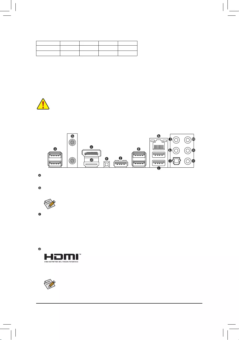
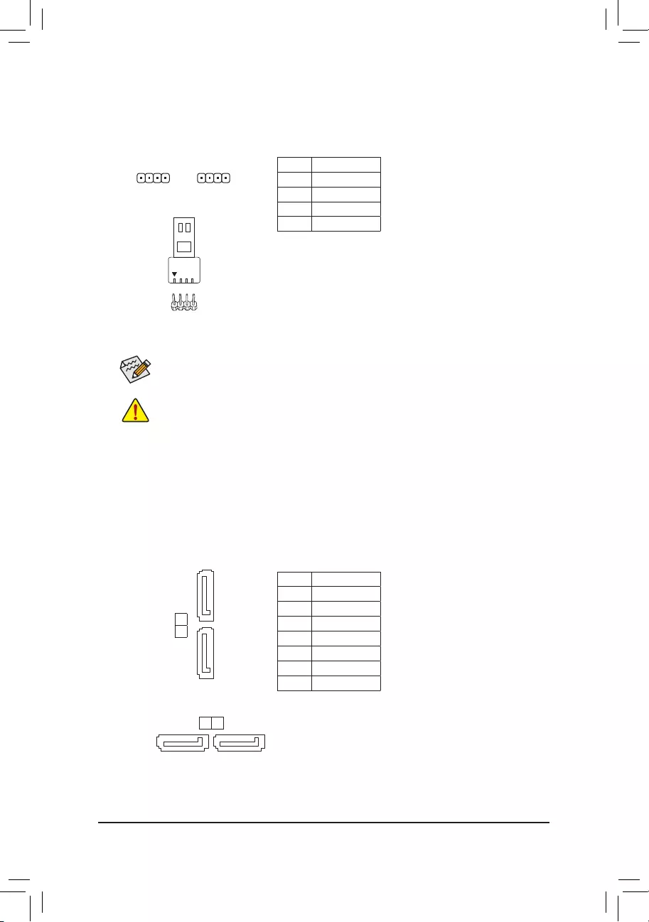
1-6 Back Panel Connectors
USB 2.0/1.1 Port
The USB port supports the USB 2.0/1.1 specication. Use this port for USB devices.
SMA Antenna Connectors (2T2R) (Note 1)
Use this connector to connect an antenna.
DisplayPort (Note 2)
DisplayPort delivers high quality digital imaging and audio, supporting bi-directional audio transmission.
DisplayPort can support both DPCP and HDCP 2.3 content protection mechanisms. It provides improved
visuals supporting Rec. 2020 (Wide Color Gamut) and High Dynamic Range (HDR) for Blu-ray UHD
playback. You can use this port to connect your DisplayPort-supported monitor. Note: The DisplayPort
Technology can support a maximum resolution of 5120×2880@60 Hz but the actual resolutions supported
depend on the monitor being used.
HDMI Port (Note 2)
The HDMI port is HDCP 2.3 compliant and supports Dolby TrueHD and DTS
HD Master Audio formats. It also supports up to 192KHz/24bit 7.1-channel
LPCM audio output. You can use this port to connect your HDMI-supported monitor. The maximum
supported resolution is 4096×2160@60 Hz, but the actual resolutions supported are dependent on the
monitor being used.
After installing the DisplayPort/HDMI device, make sure to set the default sound playback device
to DisplayPort/HDMI. (The item name may differ depending on your operating system.)
Recommanded Dual Channel Memory Conguration:
DDR4_A1 DDR4_A2 DDR4_B1 DDR4_B2
2 Modules — — DS/SS — — DS/SS
4 Modules DS/SS DS/SS DS/SS DS/SS
(SS=Single-Sided, DS=Double-Sided, «- -«=No Memory)
Tighten the antennas to the antenna connectors and then aim the antennas correctly for better
signal reception.
— 10 —
Q-Flash Plus Button (Note 3)
Q-Flash Plus allows you to update the BIOS when your system is off (S5 shutdown state). Save the latest
BIOS on a USB thumb drive and plug it into the Q-Flash Plus port, and then you can now ash the BIOS
automatically by simply pressing the Q-Flash Plus button. The QFLED will ash when the BIOS matching
and ashing activities start and will stop ashing when the BIOS ashing is complete.
USB 3.2 Gen 1 Port (Q-Flash Plus Port)
The USB 3.2 Gen 1 port supports the USB 3.2 Gen 1 specication and is compatible to the USB 2.0
specication. Use this port for USB devices. Before using Q-Flash Plus (Note 3), make sure to insert the
USB ash drive into this port rst.
USB 3.2 Gen 2 Type-A Port (Red)
The USB 3.2 Gen 2 Type-A port supports the USB 3.2 Gen 2 specication and is compatible to the USB
3.2 Gen 1 and USB 2.0 specication. Use this port for USB devices.
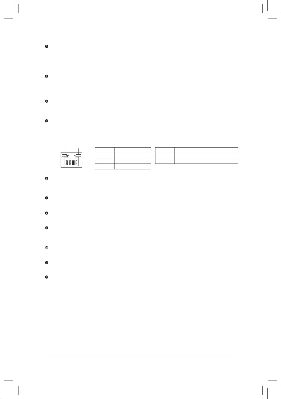
RJ-45 LAN Port
The Gigabit Ethernet LAN port provides Internet connection at up to 2.5 Gbps data rate. The following
describes the states of the LAN port LEDs.
USB 3.2 Gen 1 Port
The USB 3.2 Gen 1 port supports the USB 3.2 Gen 1 specication and is compatible to the USB 2.0
specication.
Center/Subwoofer Speaker Out
Use this audio jack to connect center/subwoofer speakers.
Rear Speaker Out
Use this audio jack to connect rear speakers.
Optical S/PDIF Out Connector
This connector provides digital audio out to an external audio system that supports digital optical audio.
Before using this feature, ensure that your audio system provides an optical digital audio in connector.
Line In/Side Speaker Out
The line in jack. Use this audio jack for line in devices such as an optical drive, walkman, etc.
Line Out/Front Speaker Out
The line out jack.
Mic In/Side Speaker Out
The Mic in jack.
Connection/
Speed LED Activity LED
LAN Port
Connection/Speed LED:
State Description
Orange 2.5 Gbps data rate
Green 1 Gbps data rate
Off 100 Mbps data rate
Activity LED:
State Description
Blinking Data transmission or receiving is occurring
Off No data transmission or receiving is occurring
(Note 1) Only for the B550 AORUS ELITE AX V2.
(Note 2) For 3rd Generation AMD Ryzen™ with Radeon™ Graphics processors only.
(Note 3) To enable the Q-Flash Plus function please visit the «Unique Features» webpage of GIGABYTE’s
website.
— 11 —
Audio Jack Congurations:
Jack Headphone/
2-channel 4-channel 5.1-channel 7.1-channel
Center/Subwoofer Speaker Out a a
Rear Speaker Out aaa
Line In/Side Speaker Out a
Line Out/Front Speaker Out aaaa
Mic In/Side Speaker Out a
If you want to install a Side Speaker, you need to retask either the Line in or Mic in jack to be Side
Speaker out through the audio driver.
•When removing the cable connected to a back panel connector, rst remove the cable from
your device and then remove it from the motherboard.
•When removing the cable, pull it straight out from the connector. Do not rock it side to side to
prevent an electrical short inside the cable connector.
Please visit GIGABYTE’s website for details on conguring the audio software.
— 12 —
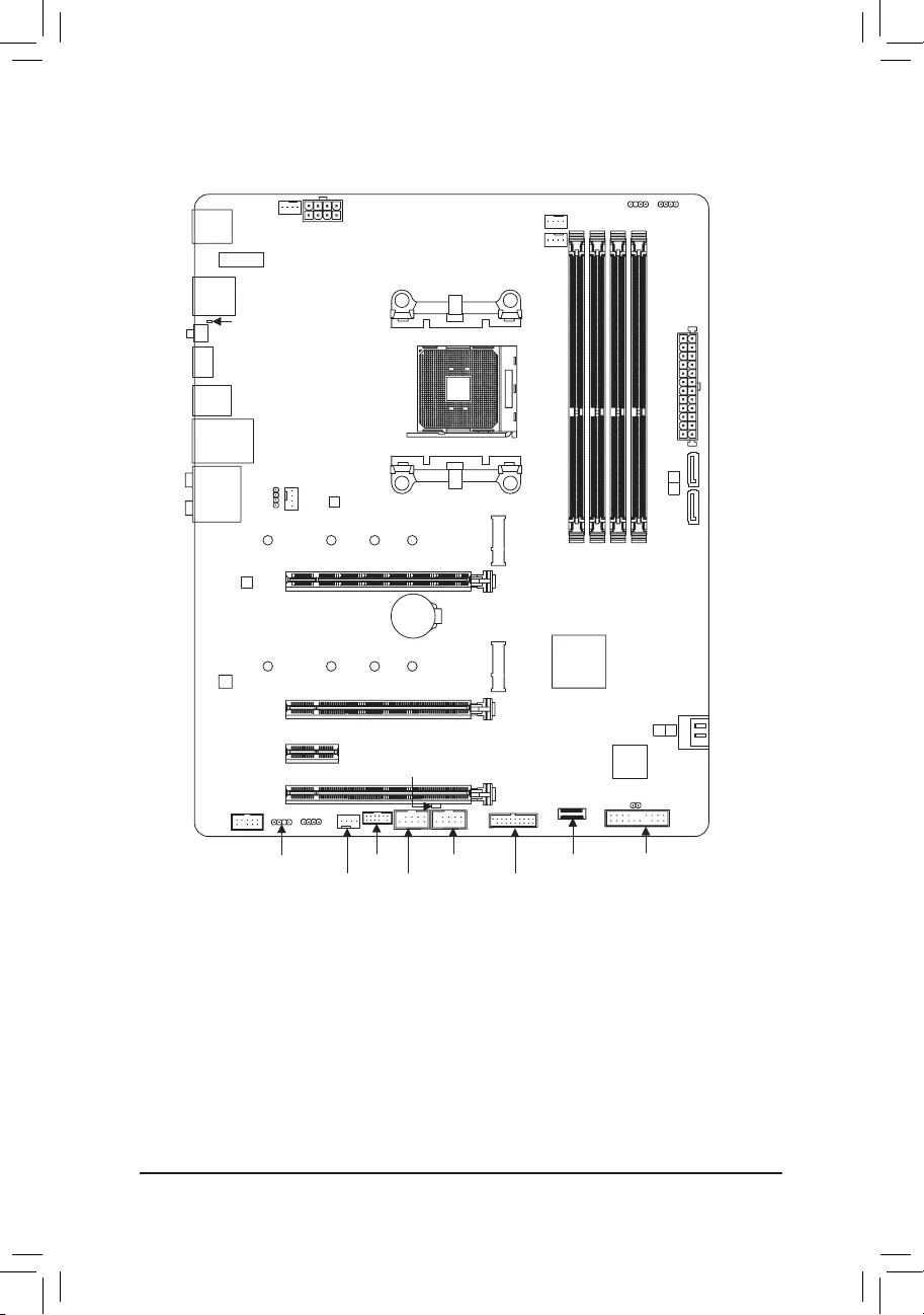
1-7 Internal Connectors
Read the following guidelines before connecting external devices:
•First make sure your devices are compliant with the connectors you wish to connect.
•Before installing the devices, be sure to turn off the devices and your computer. Unplug the power
cord from the power outlet to prevent damage to the devices.
•After installing the device and before turning on the computer, make sure the device cable has
been securely attached to the connector on the motherboard.
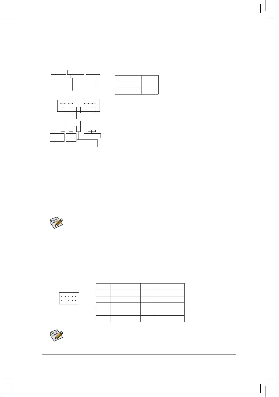
1) ATX_12V
2) ATX
3) CPU_FAN
4) SYS_FAN1/2/3
5) CPU_OPT
6) LED_CPU
7) D_LED1/D_LED2
 LED_C1/LED_C2
9) SATA3 0/1/2/3
10) M2A_CPU/M2B_SB
11) F_PANEL
12) F_ AUDIO
13) F_U32C
14) F_U32
15) F_USB1/F_USB2
16) TPM
17) CLR_CMOS
18) BAT
1
4
4
10
9
4
2
3
1115
10
9
6
5
8
7
7 8 16
12
14
17
18
13
— 13 —
131
2412
ATX
1/2) ATX_12V/ATX (2×4 12V Power Connector and 2×12 Main Power Connector)
With the use of the power connector, the power supply can supply enough stable power to all the components
on the motherboard. Before connecting the power connector, rst make sure the power supply is turned
off and all devices are properly installed. The power connector possesses a foolproof design. Connect the
power supply cable to the power connector in the correct orientation.
The 12V power connector mainly supplies power to the CPU. If the 12V power connector is not connected,
the computer will not start.
To meet expansion requirements, it is recommended that a power supply that can withstand high
power consumption be used (500W or greater). If a power supply is used that does not provide the
required power, the result can lead to an unstable or unbootable system.
ATX:
Pin No. Denition Pin No. Denition
1 3.3V 13 3.3V
2 3.3V 14 -12V
3 GND 15 GND
4 +5V 16 PS_ON (soft On/Off)
5 GND 17 GND
6 +5V 18 GND
7 GND 19 GND
8 Power Good 20 NC
9 5VSB (stand by +5V) 21 +5V
10 +12V 22 +5V
11 +12V (Only for 2×12-pin
ATX)
23 +5V (Only for 2×12-pin ATX)
12 3.3V (Only for 2×12-pin ATX) 24 GND (Only for 2×12-pin ATX)
ATX_12V:
Pin No. Denition Pin No. Denition
1 GND (Only for 2×4-pin 12V) 5 +12V (Only for 2×4-pin 12V)
2 GND (Only for 2×4-pin 12V) 6 +12V (Only for 2×4-pin 12V)
3 GND 7 +12V
4 GND 8 +12V
ATX_12V
41
85
3/4) CPU_FAN/SYS_FAN1/2/3 (Fan Headers)
All fan headers on this motherboard are 4-pin. Most fan headers possess a foolproof insertion design.
When connecting a fan cable, be sure to connect it in the correct orientation (the black connector wire is
the ground wire). The speed control function requires the use of a fan with fan speed control design. For
optimum heat dissipation, it is recommended that a system fan be installed inside the chassis.
Pin No. Denition
1 GND
2 Voltage Speed Control
3 Sense
4 PWM Speed Control
•Be sure to connect fan cables to the fan headers to prevent your CPU and system from
overheating. Overheating may result in damage to the CPU or the system may hang.
•These fan headers are not conguration jumper blocks. Do not place a jumper cap on the headers.
CPU_FAN/SYS_FAN1 SYS_FAN3
1
1
SYS_FAN2
1
— 14 —
5) CPU_OPT (Water Cooling CPU Fan Header)
The fan header is 4-pin and possesses a foolproof insertion design. Most fan headers possess a foolproof
insertion design. When connecting a fan cable, be sure to connect it in the correct orientation (the black
connector wire is the ground wire). The speed control function requires the use of a fan with fan speed control
design.
1
Pin No. Denition
1 GND
2 Voltage Speed Control
3 Sense
4 PWM Speed Control
•Be sure to connect fan cables to the fan headers to prevent your CPU and system from
overheating. Overheating may result in damage to the CPU or the system may hang.
•These fan headers are not conguration jumper blocks. Do not place a jumper cap on the headers.
6) LED_CPU (CPU Cooler LED Strip/RGB LED Strip Header)
The header can be used to connect a CPU cooler LED strip or a standard 5050 RGB LED strip (12V/G/R/B),
with maximum power rating of 2A (12V) and maximum length of 2m.
Pin No. Denition
1 12V
2 G
3 R
4 B
Connect the CPU cooler LED strip/RGB LED strip to the header. The
power pin (marked with a triangle on the plug) of the LED strip must
be connected to Pin 1 (12V) of this header. Incorrect connection
may lead to the damage of the LED strip.
RGB LED
Strip
1
12V
1
Before installing the devices, be sure to turn off the devices and your computer. Unplug the power
cord from the power outlet to prevent damage to the devices.
For how to turn on/off the lights of the LED strip please visit the «Unique Features» webpage of
GIGABYTE’s website.
7) D_LED1/D_LED2 (Addressable LED Strip Headers)
The headers can be used to connect a standard 5050 addressable LED strip, with maximum power rating
of 5A (5V) and maximum number of 1000 LEDs.
Pin No. Denition
1 V (5V)
2 Data
3 No Pin
4 GND
Connect your addressable LED strip to the header. The power
pin (marked with a triangle on the plug) of the LED strip must be
connected to Pin 1 of the addressable LED strip header. Incorrect
connection may lead to the damage of the LED strip.
Addressable LED
Strip
1
D_LED1 D_LED2
1
F_USB30 F_U
B_
F_ F_
_
B
BS_
B
SB_
B
_S
S_
_
B
_U
_
B
S
123
123
123
123
1
1
1
1
BSS
S
_S
SSU
1 2 3 4 5
S3 BSSS
U
__ 3
F_USB3F
S _
S _
S _
SF
B_
B_
F
_0
S
S
_0F
_F
_
_
__B
U
S _S
_ SF_
B
USB0_B
B_
B_
F_USB3
F_USB303
_
_3U
S_
F_USB30 F_U
B_
F_ F_
_
B
BS_
B
SB_
B
_S
S_
_
B
_U
_
B
S
123
123
123
123
1
1
1
1
BSS
S
_S
SSU
1 2 3 4 5
S3 BSSS
U
__ 3
F_USB3F
S _
S _
S _
SF
B_
B_
F
_0
S
S
_0F
_F
_
_
__B
U
S _S
_ SF_
B
USB0_B
B_
B_
F_USB3
F_USB303
_
_3U
S_
1
— 15 —
Before installing the devices, be sure to turn off the devices and your computer. Unplug the power
cord from the power outlet to prevent damage to the devices.
LED_C1/LED_C2 (RGB LED Strip Headers)
The headers can be used to connect a standard 5050 RGB LED strip (12V/G/R/B), with maximum power
rating of 2A (12V) and maximum length of 2m.
Pin No. Denition
1 12V
2 G
3 R
4 B
For how to turn on/off the lights of the LED strip please visit the «Unique Features» webpage of
GIGABYTE’s website.
1 1
LED_C1 LED_C2
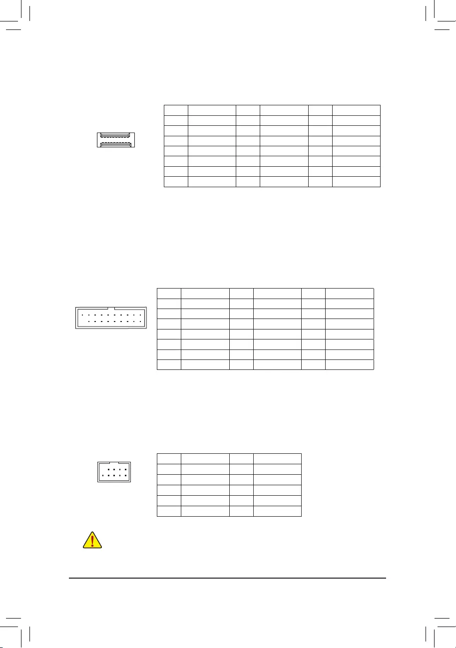
9) SATA3 0/1/2/3 (SATA 6Gb/s Connectors)
The SATA connectors conform to SATA 6Gb/s standard and are compatible with SATA 3Gb/s and SATA
1.5Gb/s standard. Each SATA connector supports a single SATA device. The SATA connectors support
RAID 0, RAID 1, and RAID 10. Refer to Chapter 3, «Conguring a RAID Set,» for instructions on conguring
a RAID array.
Pin No. Denition
1 GND
2 TXP
3 TXN
4 GND
5 RXN
6 RXP
7 GND
SATA3 0
1
7
1
1 7
SATA3
3 2
Connect your RGB LED strip to the header. The power pin (marked
with a triangle on the plug) of the LED strip must be connected to
Pin 1 (12V) of this header. Incorrect connection may lead to the
damage of the LED strip.
RGB LED Strip
1
12V
— 16 —
10) M2A_CPU/M2B_SB (M.2 Socket 3 Connectors)
The M.2 connectors support M.2 SATA SSDs or M.2 PCIe SSDs and support RAID conguration. Please
note that an M.2 PCIe SSD cannot be used to create a RAID set either with an M.2 SATA SSD or a SATA
hard drive. Refer to Chapter 3, «Conguring a RAID Set,» for instructions on conguring a RAID array.
Follow the steps below to correctly install an M.2 SSD in the M.2 connector.
Step 1:
Locate the M.2 connector where you will install the M.2 SSD, use a screwdriver to unfasten the screw on
the heatsink and then remove the heatsink.
Step 2:
Locate the proper mounting hole based on the length of your M.2 SSD drive. If needed, move the standoff
to the desired mounting hole. Insert the M.2 SSD into the M.2 connector at an angle.
Step 3:
Press the M.2 SSD down and then secure it with the screw. Replace the heatsink and secure it to the
original hole. Make sure to remove the protective lm from the bottom of the heatsink before replacing the heatsink.
Select the proper hole for the M.2 SSD to be installed and refasten the screw and standoff.
F_USB30 F_U
B_
F_ F_
_
B
BS_
B
SB_
B
_S
S_
_
B
_U
_
B
S
123
123
123
123
1
1
1
1
BSS
S
_S
SSU
1 2 3 4 5
S3 BSSS
U
__ 3
F_USB3F
S _
S _
S _
SF
B_
B_
F
_0
S
S
_0F
_F
_
_
__B
U
S _S
_ SF_
B
USB0_B
B_
B_
F_USB3
F_USB303
_
_3U
S_
80110 60 42
M2A_CPU
F_USB30 F_U
B_
F_ F_
_
B
BS_
B
SB_
B
_S
S_
_
B
_U
_
B
S
123
123
123
123
1
1
1
1
BSS
S
_S
SSU
1 2 3 4 5
S3 BSSS
U
__ 3
F_USB3F
S _
S _
S _
SF
B_
B_
F
_0
S
S
_0F
_F
_
_
__B
U
S _S
_ SF_
B
USB0_B
B_
B_
F_USB3
F_USB303
_
_3U
S_
80110 60 42
M2B_SB (Note)
(Note) Only the B550 AORUS ELITE AX V2 has the heatsink.
— 17 —
Some chassis provide a front panel audio module that has separated connectors on each wire
instead of a single plug. For information about connecting the front panel audio module that has
different wire assignments, please contact the chassis manufacturer.
11) F_PANEL (Front Panel Header)
Connect the power switch, reset switch, speaker, chassis intrusion switch/sensor and system status indicator
on the chassis to this header according to the pin assignments below. Note the positive and negative pins
before connecting the cables.
12) F_AUDIO (Front Panel Audio Header)
The front panel audio header supports High Denition audio (HD). You may connect your chassis front
panel audio module to this header. Make sure the wire assignments of the module connector match the
pin assignments of the motherboard header. Incorrect connection between the module connector and the
motherboard header will make the device unable to work or even damage it.
F_USB30 F_U
B_
F_ F_
_
B
BS_
B
SB_
B
_S
S_
_
B
_U
_
B
S
123
123
123
123
1
1
1
1
BSS
S
_S
SSU
1 2 3 4 5
S3 BSSS
U
__ 3
F_USB3F
S _
S _
S _
SF
B_
B_
F
_0
S
S
_0F
_F
_
_
__B
U
S _S
_ SF_
B
USB0_B
B_
B_
F_USB3
F_USB303
_
_3U
S_
91
10 2
Pin No. Denition Pin No. Denition
1 MIC2_L 6 Sense
2 GND 7 FAUDIO_JD
3 MIC2_R 8 No Pin
4 NC 9 LINE2_L
5 LINE2_R 10 Sense
The front panel design may differ by chassis. A front panel module mainly consists of power switch,
reset switch, power LED, hard drive activity LED, speaker and etc. When connecting your chassis
front panel module to this header, make sure the wire assignments and the pin assignments are
matched correctly.
System Status LED
S0 On
S3/S4/S5 Off
•PW (Power Switch):
Connects to the power switch on the chassis front panel. You may
congure the way to turn off your system using the power switch
(refer to Chapter 2, «BIOS Setup,» «Settings\Platform Power,» for more
information).
•SPEAK (Speaker):
Connects to the speaker on the chassis front panel. The system reports
system startup status by issuing a beep code. One single short beep
will be heard if no problem is detected at system startup.
•PLED/PWR_LED (Power LED):
Connects to the power status indicator
on the chassis front panel. The LED is on
when the system is operating. The LED is
off when the system is in S3/S4 sleep state
or powered off (S5).
•HD (Hard Drive Activity LED):
Connects to the hard drive activity LED on the chassis front panel. The LED is on when the hard drive
is reading or writing data.
•RES (Reset Switch):
Connects to the reset switch on the chassis front panel. Press the reset switch to restart the computer
if the computer freezes and fails to perform a normal restart.
•CI (Chassis Intrusion Header):
Connects to the chassis intrusion switch/sensor on the chassis that can detect if the chassis cover has
been removed. This function requires a chassis with a chassis intrusion switch/sensor.
•NC: No connection.
NC
NC
Power LED
1
2
19
20
CI-
CI+
PWR_LED-
PWR_LED+
PLED-
PW-
SPEAK+
SPEAK-
PLED+
PW+
Power LED
HD-
RES+
HD+
RES-
Hard Drive
Activity LED
Reset
Switch Chassis Intrusion
Header
Power Switch Speaker
PWR_LED-
— 18 —
Pin No. Denition Pin No. Denition Pin No. Denition
1 VBUS 8 D1- 15 SSTX2-
2 SSRX1- 9 D1+ 16 GND
3 SSRX1+ 10 NC 17 SSRX2+
4 GND 11 D2+ 18 SSRX2-
5 SSTX1- 12 D2- 19 VBUS
6 SSTX1+ 13 GND 20 No Pin
7 GND 14 SSTX2+
14) F_U32 (USB 3.2 Gen 1 Header)
The header conforms to USB 3.2 Gen 1 and USB 2.0 specication and can provide two USB ports. For
purchasing the optional 3.5″ front panel that provides two USB 3.2 Gen 1 ports, please contact the local
dealer.
F_USB30 F_U
B_
F_ F_
_
B
BS_
B
SB_
B
_S
S_
_
B
_U
_
B
S
123
123
123
123
1
1
1
1
BSS
S
_S
SSU
1 2 3 4 5
S3 BSSS
U
__ 3
F_USB3F
S _
S _
S _
SF
B_
B_
F
_0
S
S
_0F
_F
_
_
__B
U
S _S
_ SF_
B
USB0_B
B_
B_
F_USB3
F_USB303
_
_3U
S_
11
1 10
20
15) F_USB1/F_USB2 (USB 2.0/1.1 Headers)
The headers conform to USB 2.0/1.1 specication. Each USB header can provide two USB ports via an
optional USB bracket. For purchasing the optional USB bracket, please contact the local dealer.
Pin No. Denition Pin No. Denition
1 Power (5V) 6 USB DY+
2 Power (5V) 7 GND
3 USB DX- 8 GND
4 USB DY— 9 No Pin
5 USB DX+ 10 NC
•Do not plug the IEEE 1394 bracket (2×5-pin) cable into the USB 2.0/1.1 header.
•Prior to installing the USB bracket, be sure to turn off your computer and unplug the power cord
from the power outlet to prevent damage to the USB bracket.
10
9
2
1
13) F_U32C (USB Type-C™ Header with USB 3.2 Gen 1 Support)
The header conforms to USB 3.2 Gen 1 specication and can provide one USB port.
Pin No. Denition Pin No. Denition Pin No. Denition
1 VBUS 8 CC1 15 RX2+
2 TX1+ 9 SBU1 16 RX2-
3 TX1- 10 SBU2 17 GND
4 GND 11 VBUS 18 D-
5 RX1+ 12 TX2+ 19 D+
6 RX1- 13 TX2- 20 CC2
7 VBUS 14 GND
F_USB30 F_U
B_
F_ F_
_
B
BS_
B
SB_
B
_S
S_
_
B
_U
_
B
S
123
123
123
123
1
1
1
1
BSS
S
_S
SSU
1 2 3 4 5
S3 BSSS
U
__ 3
F_USB3F
S _
S _
S _
SF
B_
B_
F
_0
S
S
_0F
_F
_
_
__B
U
S _S
_ SF_
B
USB0_B
B_
B_
F_USB3
F_USB303
_
_3U
S_
20
10
11
1
— 19 —
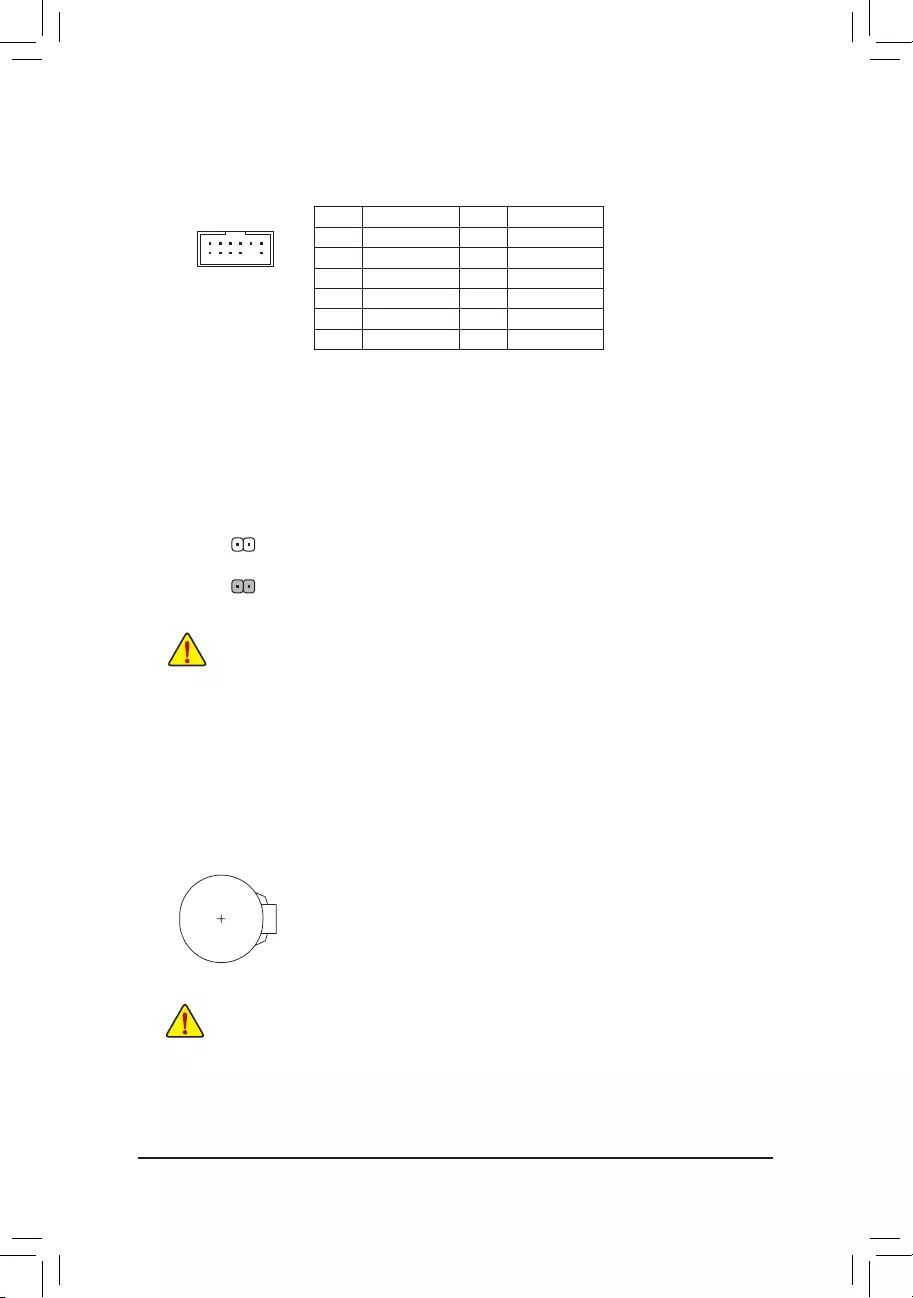
17) CLR_CMOS (Clear CMOS Jumper)
Use this jumper to clear the BIOS conguration and reset the CMOS values to factory defaults. To clear
the CMOS values, use a metal object like a screwdriver to touch the two pins for a few seconds.
•Always turn off your computer before clearing the CMOS values.
•After system restart, go to BIOS Setup to load factory defaults (select Load Optimized Defaults) or
manually congure the BIOS settings (refer to Chapter 2, «BIOS Setup,» for BIOS congurations).
Open: Normal
Short: Clear CMOS Values
18) BAT (Battery)
The battery provides power to keep the values (such as BIOS congurations, date, and time information)
in the CMOS when the computer is turned off. Replace the battery when the battery voltage drops to a low
level, or the CMOS values may not be accurate or may be lost.
You may clear the CMOS values by removing the battery:
1. Turn off your computer and unplug the power cord.
2. Gently remove the battery from the battery holder and wait for one minute. (Or use a metal
object like a screwdriver to touch the positive and negative terminals of the battery holder,
making them short for 5 seconds.)
3. Replace the battery.
4. Plug in the power cord and restart your computer.
•Always turn off your computer and unplug the power cord before replacing the battery.
•Replace the battery with an equivalent one. Damage to your devices may occur if the battery is
replaced with an incorrect model.
•Contact the place of purchase or local dealer if you are not able to replace the battery by yourself
or uncertain about the battery model.
•When installing the battery, note the orientation of the positive side (+) and the negative side (-)
of the battery (the positive side should face up).
•Used batteries must be handled in accordance with local environmental regulations.
16) TPM (Trusted Platform Module Header)
You may connect a TPM (Trusted Platform Module) to this header.
Pin No. Denition Pin No. Denition
1LAD0 7LAD3
2VCC3 8GND
3LAD1 9LFRAME
4No Pin 10 NC
5LAD2 11 SERIRQ
6LCLK 12 LRESET
12
11
2
1
F_USB30 F_U
B_
F_ F_
_
B
BS_
B
SB_
B
_S
S_
_
B
_U
_
B
S
123
123
123
123
1
1
1
1
BSS
S
_S
SSU
1 2 3 4 5
S3 BSSS
U
__ 3
F_USB3F
S _
S _
S _
SF
B_
B_
F
_0
S
S
_0F
_F
_
_
__B
U
S _S
_ SF_
B
USB0_B
B_
B_
F_USB3
F_USB303
_
_3U
S_
— 20 —
BIOS (Basic Input and Output System) records hardware parameters of the system in the CMOS on the
motherboard. Its major functions include conducting the Power-On Self-Test (POST) during system startup,
saving system parameters and loading operating system, etc. BIOS includes a BIOS Setup program that allows
the user to modify basic system conguration settings or to activate certain system features.
When the power is turned off, the battery on the motherboard supplies the necessary power to the CMOS to
keep the conguration values in the CMOS.
To access the BIOS Setup program, press the <Delete> key during the POST when the power is turned on.
To upgrade the BIOS, use either the GIGABYTE Q-Flash or @BIOS utility.
•Q-Flash allows the user to quickly and easily upgrade or back up BIOS without entering the operating system.
•@BIOS is a Windows-based utility that searches and downloads the latest version of BIOS from the Internet
and updates the BIOS.
Chapter 2 BIOS Setup
•Because BIOS ashing is potentially risky, if you do not encounter problems using the current version of BIOS,
it is recommended that you not ash the BIOS. To ash the BIOS, do it with caution. Inadequate BIOS ashing
may result in system malfunction.
•It is recommended that you not alter the default settings (unless you need to) to prevent system instability or other
unexpected results. Inadequately altering the settings may result in system’s failure to boot. If this occurs, try to
clear the CMOS values and reset the board to default values. (Refer to the «Load Optimized Defaults» section in
this chapter or introductions of the battery/clear CMOS jumper in Chapter 1 for how to clear the CMOS values.)
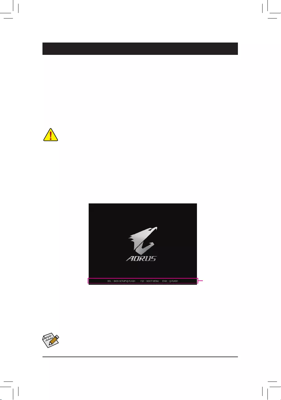
2-1 Startup Screen
The following startup Logo screen will appear when the computer boots.
Function Keys
•When the system is not stable as usual, select the Load Optimized Defaults item to set your system to its defaults.
•The BIOS Setup menus described in this chapter are for reference only and may differ by BIOS version.
There are two different BIOS modes as follows and you can use the <F2> key to switch between the two modes.
Easy Mode allows users to quickly view their current system information or to make adjustments for optimum
performance. In Easy Mode, you can use your mouse to move through conguration items. The Advanced Mode
provides detailed BIOS settings. You can press the arrow keys on your keyboard to move among the items
and press <Enter> to accept or enter a sub-menu. Or you can use your mouse to select the item you want.
— 21 —
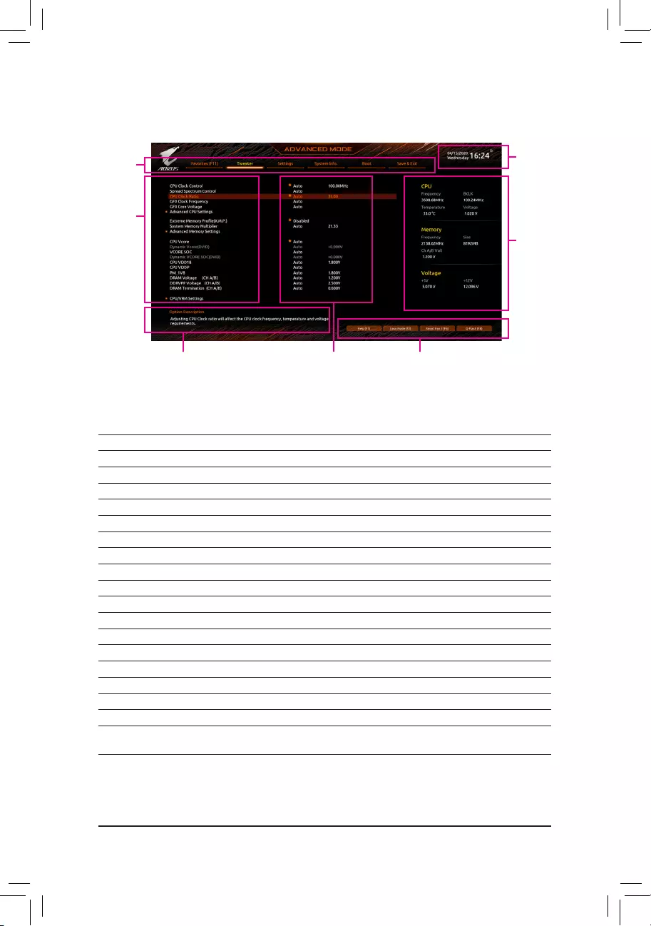
2-2 The Main Menu
Advanced Mode Function Keys
<f><g> Move the selection bar to select a setup menu
<h><i>Move the selection bar to select an conguration item on a menu
<Enter>/Double Click Execute command or enter a menu
<+>/<Page Up> Increase the numeric value or make changes
<—>/<Page Down> Decrease the numeric value or make changes
<F1> Show descriptions of the function keys
<F2> Switch to Easy Mode
<F3> Save the current BIOS settings to a prole
<F4> Load the BIOS settings from a prole created before
<F5> Restore the previous BIOS settings for the current submenus
<F6> Display the Smart Fan 5 screen
<F7> Load the Optimized BIOS default settings for the current submenus
<F8> Access the Q-Flash utility
<F10> Save all the changes and exit the BIOS Setup program
<F11> Switch to the Favorites submenu
<F12> Capture the current screen as an image and save it to your USB drive
<Insert> Add or remove a favorite option
<Ctrl>+<S> Display information on the installed memory
<Esc> Main Menu: Exit the BIOS Setup program
Submenus: Exit current submenu
Hardware
Information
Option Description Current Settings
Setup Menus
Conguration
Items
System
Time
Quick Access Bar allows you to quickly move to
the General Help, Easy Mode, Smart Fan 5, or
Q-Flash screen.
— 22 —
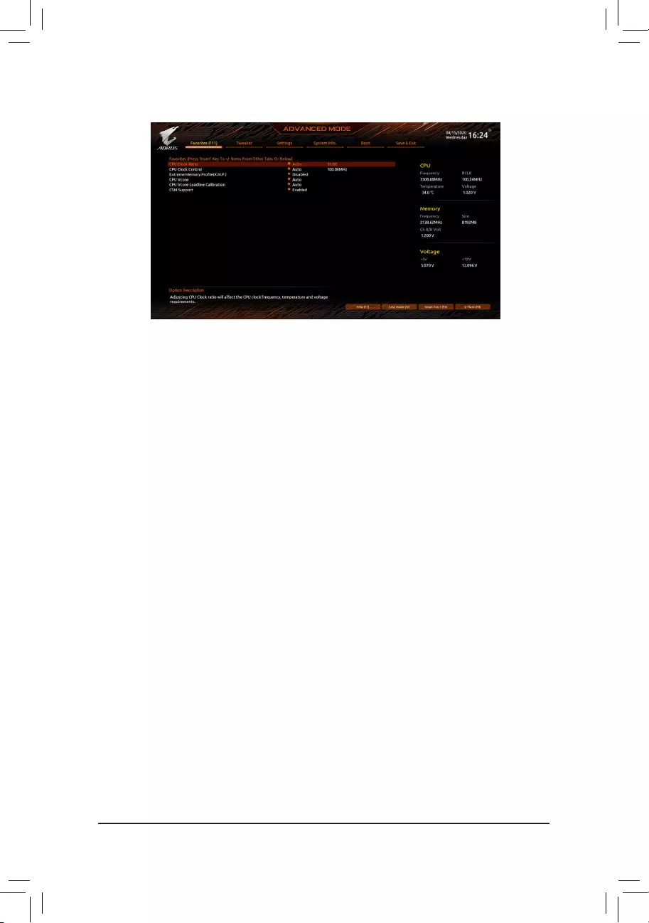
2-3 Favorites (F11)
Set your frequently used options as your favorites and use the <F11> key to quickly switch to the page where
all of your favorite options are located. To add or remove a favorite option, go to its original page and press
<Insert> on the option. The option is marked with a star sign if set as a «favorite.»
— 23 —
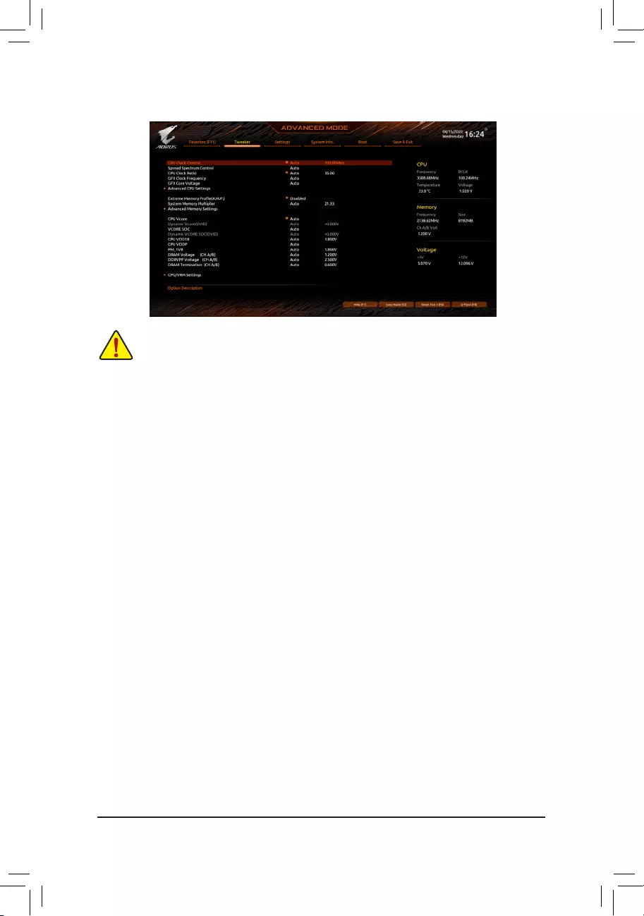
2-4 Tweaker
Whether the system will work stably with the overclock/overvoltage settings you made is dependent on your overall
system congurations. Incorrectly doing overclock/overvoltage may result in damage to CPU, chipset, or memory
and reduce the useful life of these components. This page is for advanced users only and we recommend you not to
alter the default settings to prevent system instability or other unexpected results. (Inadequately altering the settings
may result in system’s failure to boot. If this occurs, clear the CMOS values and reset the board to default values.)
&CPU Clock Control
Allows you to manually set the CPU base clock in 1 MHz increments. (Default: Auto)
Important: It is highly recommended that the CPU frequency be set in accordance with the CPU
specications.
&Spread Spectrum Control
Enables or disables CPU/PCIe Spread Spectrum. (Default: Auto)
&CPU Ratio Mode (Note)
Allows you to set the core ratio for all CPU cores or individual cores. (Default: All cores)
&CCD0 CCX0/1 Ratio (Note)
Allows you to manually set the core ratio for the CPU CCX0, 1 cores. This item is congurable only when
CPU Ratio Mode is set to Per CCX. (Default: Auto)
&CPU Clock Ratio
Allows you to alter the clock ratio for the installed CPU. The adjustable range is dependent on the CPU
being installed.
&GFX Clock Frequency (Note)
Allows you to alter the frequency for the GPU. After you alter the GFX Clock Frequency settings, make
sure to adjust the GFX Core Voltage settings. (Default: Auto)
NOTE: The adjustable range is dependent on the CPU being installed. Auto lets the BIOS automatically
congure this setting.
&GFX Core Voltage (Note)
Allows you to alter the voltage for the GPU. (Default: Auto)
NOTE: The adjustable range is dependent on the CPU being installed. Auto lets the BIOS automatically
congure this setting.
(Note) This item is present only when you install a CPU that supports this feature.
— 24 —

Advanced CPU Settings
&Core Performance Boost (Note 1)
Allows you to determine whether to enable the Core Performance Boost (CPB) technology, a CPU
performance-boost technology. (Default: Auto)
&SVM Mode
Virtualization enhanced by Virtualization Technology will allow a platform to run multiple operating systems
and applications in independent partitions. With virtualization, one computer system can function as multiple
virtual systems. (Default: Disabled)
&AMD Cool&Quiet function
Enabled Lets the AMD Cool’n’Quiet driver dynamically adjust the CPU clock and VID to
reduce heat output from your computer and its power consumption. (Default)
Disabled Disables this function.
&PPC Adjustment (Note 1)
Allows you to x the PState of the CPU. (Default: PState 0)
&Global C-state Control (Note 1)
Allows you to determine whether to let the CPU enter C states. When enabled, the CPU core frequency
will be reduced during system halt state to decrease power consumption. (Default: Auto)
&Power Supply Idle Control (Note 1)
Enables or disables Package C6 State.
Typical Current Idle Disables this function.
Low Current Idle Enables this function.
Auto Lets the BIOS automatically congure this setting. (Default)
&CCD Control (Note 1)
Sets the number of CCDs to be used. (Default: Auto)
&Downcore Control
Allows you to select the number of CPU cores to enable (the number of CPU cores may vary by CPU).
(Default: Auto)
&SMT Mode
Allows you to enable or disable the CPU Simultaneous Multi-Threading technology. (Default: Auto)
&CPPC (Note 1)
Enables or disables the CPPC feature. (Default: Auto)
&CPPC Preferred Cores (Note 1)
Enables or disables the CPPC Preferred Cores feature. (Default: Auto)
&ExtremeMemoryProle(X.M.P.)(Note 2)
Allows the BIOS to read the SPD data on XMP memory module(s) to enhance memory performance when
enabled.
Disabled Disables this function. (Default)
Prole1 Uses Prole 1 settings.
Prole2 (Note 2) Uses Prole 2 settings.
&XMP High Frequency Support (Note 2)
Allows you to select the compatibility level for high-frequency memory. This item is congurable only when
ExtremeMemoryProle(X.M.P.) is set to Prole1 or Prole2. (Default: Auto)
&System Memory Multiplier
Allows you to set the system memory multiplier. Auto sets memory multiplier according to memory SPD
data. (Default: Auto)
(Note 1) This item is present only when you install a CPU that supports this feature.
(Note 2) This item is present only when you install a CPU and a memory module that support this feature.
— 25 —

Advanced Memory Settings
Memory Subtimings
d Standard Timing Control, Advanced Timing Control, CAD Bus Setup Timing, CAD Bus
DriveStrength,DataBusConguration
These sections provide memory timing settings. Note: Your system may become unstable or fail to boot
after you make changes on the memory timings. If this occurs, please reset the board to default values by
loading optimized defaults or clearing the CMOS values.
SPD Info
Displays information on the installed memory.
& CPU Vcore/Dynamic Vcore(DVID)/VCORE SOC/Dynamic VCORE SOC(DVID)/CPU VDD18/
CPU VDDP/PM_1V8/DRAM Voltage (CH A/B)/DDRVPP Voltage (CH A/B)/DRAM Termination
(CH A/B)
These items allow you to adjust the CPU Vcore and memory voltages.
CPU/VRM Settings
This submenu allows you to congure Load-Line Calibration level, over-voltage protection level, over-current
protection level, and PWM phases.
— 26 —
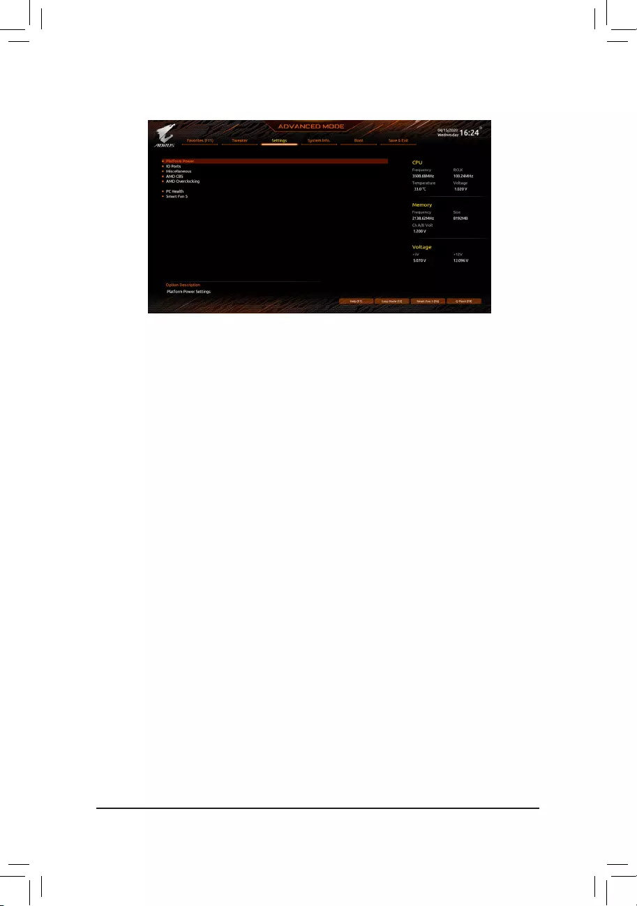
2-5 Settings
Platform Power
&AC BACK
Determines the state of the system after the return of power from an AC power loss.
Memory The system returns to its last known awake state upon the return of the AC power.
Always On The system is turned on upon the return of the AC power.
Always Off The system stays off upon the return of the AC power. (Default)
&ErP
Determines whether to let the system consume least power in S5 (shutdown) state. (Default: Disabled)
Note: When this item is set to Enabled, the Resume by Alarm function becomes unavailable.
&Soft-Off by PWR-BTTN
Congures the way to turn off the computer in MS-DOS mode using the power button.
Instant-Off Press the power button and then the system will be turned off instantly. (Default)
Delay 4 Sec. Press and hold the power button for 4 seconds to turn off the system. If the power
button is pressed for less than 4 seconds, the system will enter suspend mode.
&Power Loading
Enables or disables dummy load. When the power supply is at low load, a self-protection will activate causing
it to shutdown or fail. If this occurs, please set to Enabled. Auto lets the BIOS automatically congure this
setting. (Default: Auto)
&Resume by Alarm
Determines whether to power on the system at a desired time. (Default: Disabled)
If enabled, set the date and time as following:
Wake up day: Turn on the system at a specic time on each day or on a specic day in a month.
Wake up hour/minute/second: Set the time at which the system will be powered on automatically.
Note: When using this function, avoid inadequate shutdown from the operating system or removal of the
AC power, or the settings may not be effective.
&Wake on LAN
Enables or disables the wake on LAN function. (Default: Enabled)
&High Precision Event Timer
Enables or disables High Precision Event Timer (HPET) in the operating system. (Default: Enabled)
&CEC 2019 Ready
Allows you to select whether to allow the system to adjust power consumption when it is in shutdown, idle,
or standby state in order to comply with the CEC (California Energy Commission) 2019 Standards. (Default:
Disabled)
— 27 —

IO Ports
&Initial Display Output
Species the rst initiation of the monitor display from the installed PCI Express graphics card or the onboard
graphics.
IGD Video (Note) Sets the onboard graphics as the rst display.
PCIe 1 Slot Sets the graphics card on the PCIEX16 slot as the rst display. (Default)
PCIe 2 Slot Sets the graphics card on the PCIEX2 slot as the rst display.
&Integrated Graphics (Note)
Enables or disables the onboard graphics function.
Auto The BIOS will automatically enable or disable the onboard graphics depending
on the graphics card being installed. (Default)
Forces Enables the onboard graphics.
Disabled Disables the onboard graphics.
&UMA Mode (Note)
Specify the UMA mode.
Auto Lets the BIOS automatically congure this setting. (Default)
UMA Specied Sets the UMA Frame Buffer Size.
UMA Auto Sets the display resolution.
UMA Game Optimized Adjusts the frame buffer size based on the total system memory size.
This item is congurable only when Integrated Graphics is set to Forces.
&UMA Frame Buffer Size (Note)
Frame buffer size is the total amount of system memory allocated solely for the onboard graphics controller.
MS-DOS, for example, will use only this memory for display. Options are: Auto (default), 64M~2G.
This item is congurable only when UMA Mode is set to UMASpecied.
&Display Resolution (Note)
Allows you to set the display resolution. Options are: Auto (default), 1920×1080 and below, 2560×1600,
3840×2160. This item is congurable only when UMA Mode is set to UMA Auto.
&HD Audio Controller
Enables or disables the onboard audio function. (Default: Enabled)
If you wish to install a 3rd party add-in audio card instead of using the onboard audio, set this item to
Disabled.
&PCIEX16 Bifurcation
Allows you to determine how the bandwidth of the PCIEX16 slot is divided. Options: Auto, PCIE 2×8,
PCIE 1×8/2×4, PCIE 2×4/1×8. (Default: Auto)
&Above 4G Decoding
Enables or disables 64-bit capable devices to be decoded in above 4 GB address space (only if your system
supports 64-bit PCI decoding). Set to Enabled if more than one advanced graphics card are installed and
their drivers are not able to be launched when entering the operating system (because of the limited 4 GB
memory address space). (Default: Disabled)
&Onboard LAN Controller
Enables or disables the onboard LAN function. (Default: Enabled)
If you wish to install a 3rd party add-in network card instead of using the onboard LAN, set this item to
Disabled.
(Note) This item is present only when you install a CPU that supports this feature.
— 28 —

USBConguration
&Legacy USB Support
Allows USB keyboard/mouse to be used in MS-DOS. (Default: Enabled)
&XHCI Hand-off
Determines whether to enable XHCI Hand-off feature for an operating system without XHCI Hand-off
support. (Default: Enabled)
&USB Mass Storage Driver Support
Enables or disables support for USB storage devices. (Default: Enabled)
&Port 60/64 Emulation
Enables or disables emulation of I/O ports 64h and 60h. This should be enabled for full legacy support
for USB keyboards/mice in MS-DOS or in operating system that does not natively support USB devices.
(Default: Disabled)
&Mass Storage Devices
Displays a list of connected USB mass storage devices. This item appears only when a USB storage device
is installed.
NVMeConguration
Displays information on your M.2 NVME PCIe SSD if installed.
SATAConguration
&SATA Mode
Enables or disables RAID for the SATA controllers integrated in the Chipset or congures the SATA controllers
to AHCI mode.
RAID Enables RAID for the SATA controller.
AHCI Congures the SATA controllers to AHCI mode. Advanced Host Controller Interface
(AHCI) is an interface specication that allows the storage driver to enable advanced
Serial ATA features such as Native Command Queuing and hot plug. (Default)
&NVMe RAID mode
Allows you to determine whether to use your M.2 NVMe PCIe SSDs to congure RAID. (Default: Disabled)
&Chipset SATA Port Enable
Enables or disables the integrated SATA controllers. (Default: Enabled)
&Chipset SATA Port 0/1/2/3
Displays the information of the connected SATA device(s).
NetworkStackConguration
&Network Stack
Disables or enables booting from the network to install a GPT format OS, such as installing the OS from
the Windows Deployment Services server. (Default: Disabled)
&IPv4 PXE Support
Enables or disables IPv4 PXE Support. This item is congurable only when Network Stack is enabled.
&IPv4 HTTP Support
Enables or disables HTTP boot support for IPv4. This item is congurable only when Network Stack is
enabled.
&IPv6 PXE Support
Enables or disables IPv6 PXE Support. This item is congurable only when Network Stack is enabled.
&IPv6 HTTP Support
Enables or disables HTTP boot support for IPv6. This item is congurable only when Network Stack is
enabled.
— 29 —

&PXE boot wait time
Allows you to congure how long to wait before you can press <Esc> to abort the PXE boot. This item is
congurable only when Network Stack is enabled. (Default: 0)
&Media detect count
Allows you to set the number of times to check the presence of media. This item is congurable only when
Network Stack is enabled. (Default: 1)
Realtek PCIe 2.5GBE Family Controller
This sub-menu provides information on LAN conguration and related conguration options.
Miscellaneous
&LEDs in System Power On State
Allows you to enable or disable motherboard LED lighting when the system is on.
Off Disables the selected lighting mode when the system is on.
On Enables the selected lighting mode when the system is on. (Default)
&LEDs in Sleep, Hibernation, and Soft Off States
Allows you to set the lighting mode of the motherboard LEDs in system S3/S4/S5 state.
This item is congurable when LEDs in System Power On State is set to On.
Off Disables the selected lighting mode when the system enters S3/S4/S5 state. (Default)
On Enables the selected lighting mode when the system enters S3/S4/S5 state.
&PCIeSlotConguration
Allows you to set the operation mode of the PCI Express slots to Gen 1, Gen 2, Gen 3, or Gen 4 (Note). Actual
operation mode is subject to the hardware specication of each slot. Auto lets the BIOS automatically
congure this setting. (Default: Auto)
&3DMark01 Enhancement
Allows you to determine whether to enhance some legacy benchmark performance. (Default: Disabled)
&IOMMU
Enables or disables AMD IOMMU support. (Default: Auto)
&AMD CPU fTPM
Enables or disables the TPM 2.0 function integrated in the AMD CPU. (Default: Disabled)
Trusted Computing
Enables or disables Trusted Platform Module (TPM).
AMD CBS
This sub-menu provides AMD CBS-related conguration options.
PC Health
&Reset Case Open Status
Disabled Keeps or clears the record of previous chassis intrusion status. (Default)
Enabled Clears the record of previous chassis intrusion status and the Case Open eld will
show «No» at next boot.
&Case Open
Displays the detection status of the chassis intrusion detection device attached to the motherboard CI
header. If the system chassis cover is removed, this eld will show «Yes», otherwise it will show «No». To
clear the chassis intrusion status record, set Reset Case Open Status to Enabled, save the settings to
the CMOS, and then restart your system.
(Note) This item is present only when you install a CPU that supports this feature.
— 30 —

& CPU Vcore/CPU VDDP/DRAM Channel A/B Voltage/+3.3V/+5V/+12V/VCORE SOC
Displays the current system voltages.
Smart Fan 5
&Monitor
Allows you to select a target to monitor and to make further adjustment. (Default: CPU FAN)
&Fan Speed Control
Allows you to determine whether to enable the fan speed control function and adjust the fan speed.
Normal Allows the fan to run at different speeds according to the temperature. You can adjust
the fan speed with System Information Viewer based on your system requirements.
(Default)
Silent Allows the fan to run at slow speeds.
Manual Allows you to control the fan speed in the curve graph.
Full Speed Allows the fan to run at full speeds.
&Fan Control Use Temperature Input
Allows you to select the reference temperature for fan speed control.
&Temperature Interval
Allows you to select the temperature interval for fan speed change.
&Fan Control mode
Auto Lets the BIOS automatically detect the type of fan installed and sets the optimal control
mode. (Default)
Voltage Voltage mode is recommended for a 3-pin fan.
PWM PWM mode is recommended for a 4-pin fan.
&Fan Stop
Enables or disables the fan stop function. You can set the temperature limit using the temperature curve.
The fan or pump stops operation when the temperature is lower than the limit. (Default: Disabled)
&Temperature
Displays the current temperature of the selected target area.
&Fan Speed
Displays current fan speeds.
&Flow Rate
Displays the ow rate of your water cooling system.
&Temperature Warning Control
Sets the warning threshold for temperature. When temperature exceeds the threshold, BIOS will emit
warning sound. Options are: Disabled (default), 60oC/140oF, 70oC/158oF, 80oC/176oF, 90oC/194oF.
&Fan Fail Warning
Allows the system to emit warning sound if the fan is not connected or fails. Check the fan condition or fan
connection when this occurs. (Default: Disabled)
— 31 —
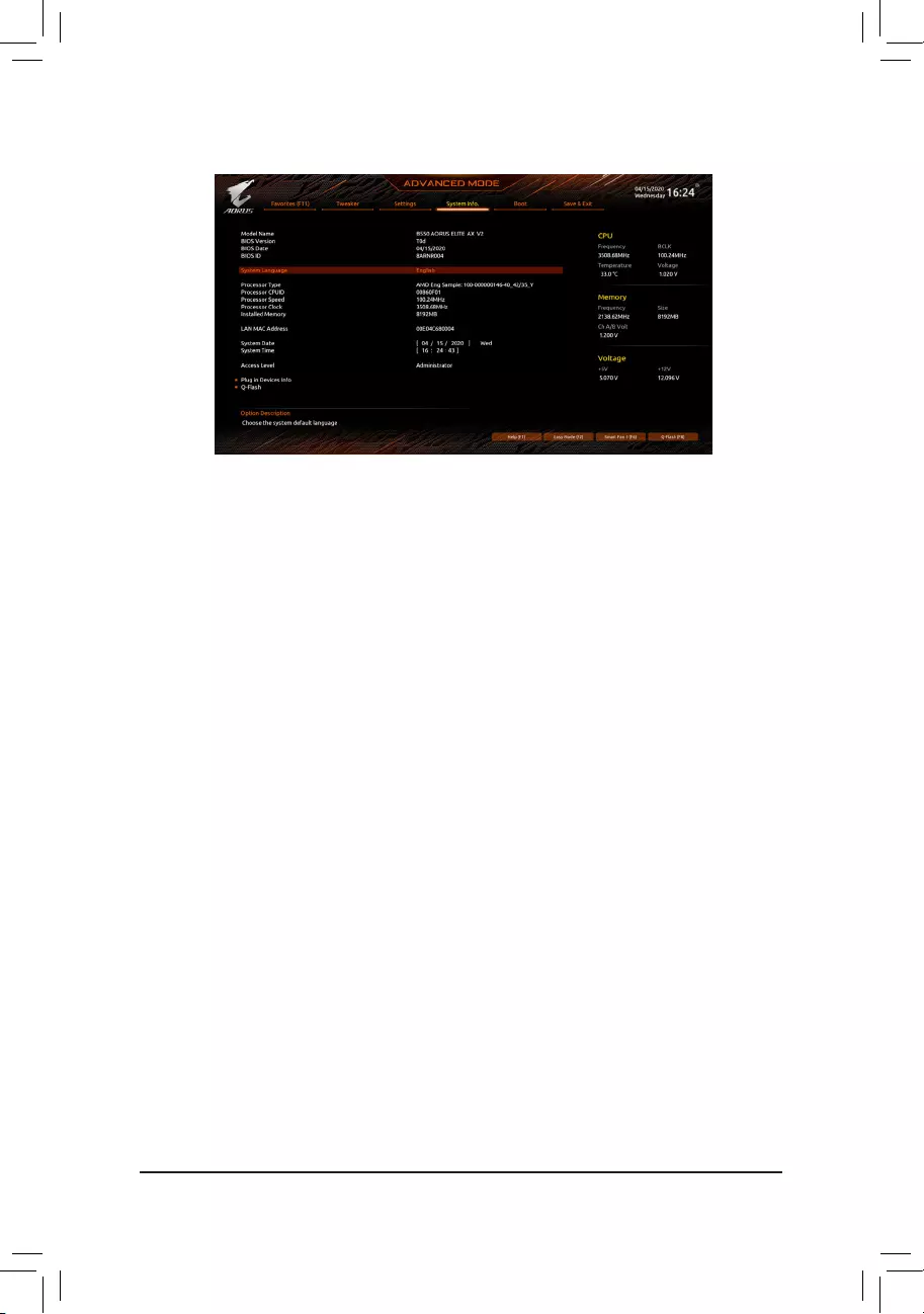
2-6 System Info.
This section provides information on your motherboard model and BIOS version. You can also select the default
language used by the BIOS and manually set the system time.
&System Language
Selects the default language used by the BIOS.
&System Date
Sets the system date. The date format is week (read-only), month, date, and year. Use <Enter> to switch
between the Month, Date, and Year elds and use the <Page Up> or <Page Down> key to set the desired
value.
&System Time
Sets the system time. The time format is hour, minute, and second. For example, 1 p.m. is 13:00:00. Use
<Enter> to switch between the Hour, Minute, and Second elds and use the <Page Up> or <Page Down>
key to set the desired value.
&Access Level
Displays the current access level depending on the type of password protection used. (If no password is
set, the default will display as Administrator.) The Administrator level allows you to make changes to all
BIOS settings; the User level only allows you to make changes to certain BIOS settings but not all.
Plug in Devices Info
Displays information on your SATA, PCI Express, and M.2 devices if installed.
Q-Flash
Allows you to access the Q-Flash utility to update the BIOS or back up the current BIOS conguration.
— 32 —
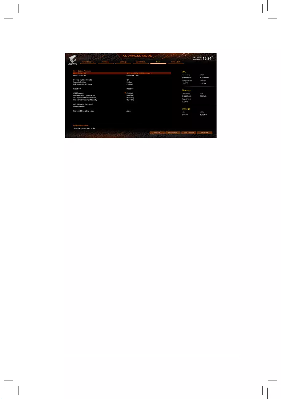
2-7 Boot
&Boot Option Priorities
Species the overall boot order from the available devices. Removable storage devices that support GPT
format will be prexed with «UEFI:» string on the boot device list. To boot from an operating system that
supports GPT partitioning, select the device prexed with «UEFI:» string.
Or if you want to install an operating system that supports GPT partitioning such as Windows 10 64-bit,
select the optical drive that contains the Windows 10 64-bit installation disc and is prexed with «UEFI:»
string.
&Bootup NumLock State
Enables or disables Numlock feature on the numeric keypad of the keyboard after the POST. (Default: On)
&Security Option
Species whether a password is required every time the system boots, or only when you enter BIOS Setup.
After conguring this item, set the password(s) under the Administrator Password/User Password item.
Setup A password is only required for entering the BIOS Setup program.
System A password is required for booting the system and for entering the BIOS Setup program.
(Default)
&Full Screen LOGO Show
Allows you to determine whether to display the GIGABYTE Logo at system startup. Disabled skips the
GIGABYTE Logo when the system starts up. (Default: Enabled)
&Fast Boot
Enables or disables Fast Boot to shorten the OS boot process. Ultra Fast provides the fastest bootup
speed. (Default: Disabled)
&SATA Support
Last Boot SATA Devices Only Except for the previous boot drive, all SATA devices are disabled
before the OS boot process completes. (Default)
All SATA Devices All SATA devices are functional in the operating system and during the POST.
This item is congurable only when Fast Boot is set to Enabled or Ultra Fast.
&NVMe Support
Allows you to enable or disable NVMe device(s). (Default: Enabled)
This item is congurable only when Fast Boot is set to Enabled or Ultra Fast.
— 33 —

&VGA Support
Allows you to select which type of operating system to boot.
Auto Enables legacy option ROM only.
EFI Driver Enables EFI option ROM. (Default)
This item is congurable only when Fast Boot is set to Enabled or Ultra Fast.
&USB Support
Disabled All USB devices are disabled before the OS boot process completes.
Full Initial All USB devices are functional in the operating system and during the POST.
(Default)
Partial Initial Part of the USB devices are disabled before the OS boot process completes.
This item is congurable only when Fast Boot is set to Enabled. This function is disabled when Fast Boot
is set to Ultra Fast.
&NetWork Stack Driver Support
Disabled Disables booting from the network. (Default)
Enabled Enables booting from the network.
This item is congurable only when Fast Boot is set to Enabled or Ultra Fast.
&CSM Support
Enables or disables UEFI CSM (Compatibility Support Module) to support a legacy PC boot process.
Disabled Disables UEFI CSM and supports UEFI BIOS boot process only.
Enabled Enables UEFI CSM. (Default)
&LAN PXE Boot Option ROM
Allows you to select whether to enable the legacy option ROM for the LAN controller. (Default: Disabled)
This item is congurable only when CSM Support is set to Enabled.
&Storage Boot Option Control
Allows you to select whether to enable the UEFI or legacy option ROM for the storage device controller.
Disabled Disables option ROM.
UEFI Only Enables UEFI option ROM only. (Default)
Legacy Only Enables legacy option ROM only.
This item is congurable only when CSM Support is set to Enabled.
&Other PCI Device ROM Priority
Allows you to select whether to enable the UEFI or Legacy option ROM for the PCI device controller other
than the LAN, storage device, and graphics controllers.
Disabled Disables option ROM.
UEFI Only Enables UEFI option ROM only. (Default)
Legacy Only Enables legacy option ROM only.
This item is congurable only when CSM Support is set to Enabled.
&Administrator Password
Allows you to congure an administrator password. Press <Enter> on this item, type the password, and
then press <Enter>. You will be requested to conrm the password. Type the password again and press
<Enter>. You must enter the administrator password (or user password) at system startup and when entering
BIOS Setup. Differing from the user password, the administrator password allows you to make changes to
all BIOS settings.
— 34 —

&User Password
Allows you to congure a user password. Press <Enter> on this item, type the password, and then press
<Enter>. You will be requested to conrm the password. Type the password again and press <Enter>.
You must enter the administrator password (or user password) at system startup and when entering BIOS
Setup. However, the user password only allows you to make changes to certain BIOS settings but not all.
To cancel the password, press <Enter> on the password item and when requested for the password, enter
the correct one rst. When prompted for a new password, press <Enter> without entering any password.
Press <Enter> again when prompted to conrm.
NOTE: Before setting the User Password, be sure to set the Administrator Password rst.
Secure Boot
Allows you to enable or disable Secure Boot and congure related settings. This item is congurable only
when CSM Support is set to Disabled.
&Preferred Operating Mode
Allows you to select whether to enter Easy mode or Advanced mode after entering BIOS Setup. Auto
enters the BIOS mode where it was last time. (Default: Auto)
— 35 —
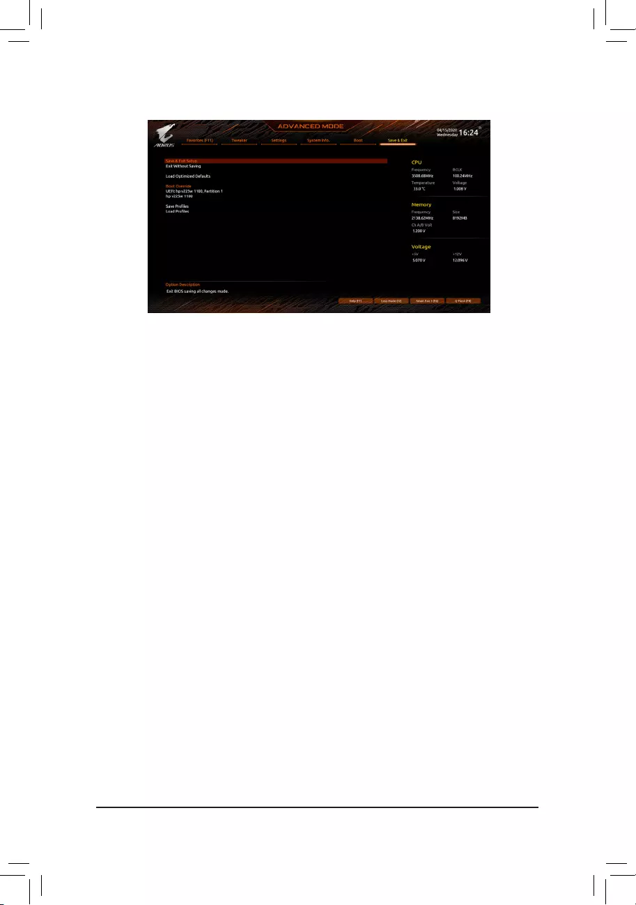
2-8 Save & Exit
&Save & Exit Setup
Press <Enter> on this item and select Yes. This saves the changes to the CMOS and exits the BIOS Setup
program. Select No or press <Esc> to return to the BIOS Setup Main Menu.
&Exit Without Saving
Press <Enter> on this item and select Yes. This exits the BIOS Setup without saving the changes made
in BIOS Setup to the CMOS. Select No or press <Esc> to return to the BIOS Setup Main Menu.
&Load Optimized Defaults
Press <Enter> on this item and select Yes to load the optimal BIOS default settings. The BIOS defaults
settings help the system to operate in optimum state. Always load the Optimized defaults after updating
the BIOS or after clearing the CMOS values.
&Boot Override
Allows you to select a device to boot immediately. Press <Enter> on the device you select and select Yes
to conrm. Your system will restart automatically and boot from that device.
&SaveProles
This function allows you to save the current BIOS settings to a prole. You can create up to 8 proles and
save as Setup Prole 1~ Setup Prole 8. Press <Enter> to complete. Or you can select Select File in
HDD/FDD/USB to save the prole to your storage device.
&LoadProles
If your system becomes unstable and you have loaded the BIOS default settings, you can use this function
to load the BIOS settings from a prole created before, without the hassles of reconguring the BIOS
settings. First select the prole you wish to load and then press <Enter> to complete. You can select Select
File in HDD/FDD/USB to input the prole previously created from your storage device or load the prole
automatically created by the BIOS, such as reverting the BIOS settings to the last settings that worked
properly (last known good record).
— 36 —
Chapter 3 Appendix
3-1 ConguringaRAIDSet
(Note) An M.2 PCIe SSD cannot be used to set up a RAID set either with an M.2 SATA SSD or a SATA hard drive.
C.UEFIRAIDConguration
Steps:
1. In BIOS Setup, go to Boot and set CSM Support to Disabled. Save the changes and exit BIOS Setup.
2. After the system reboot, enter BIOS Setup again. Then enter the Settings\IO Ports\RAIDXpert2
CongurationUtility sub-menu.
3. On the RAIDXpert2CongurationUtility screen, press <Enter> on Array Management to enter the Create
Array screen. Then, select a RAID level. RAID levels supported include RAID 0, RAID 1, and RAID 10 (the
selections available depend on the number of the hard drives being installed). Next, press <Enter> on Select
Physical Disks to enter the Select Physical Disks screen.
4. On the Select Physical Disks screen, select the hard drives to be included in the RAID array and set them
to Enabled. Next, use the down arrow key to move to Apply Changes and press <Enter>. Then return
to the previous screen and set the Select CacheTagSize, Read Cache Policy and Write Cache Policy.
5. Move to Create Array and press <Enter> to begin.
6. After completing, you’ll be brought back to the Array Management screen. Under Manage Array Properties
you can see the new RAID volume and information on RAID level, array name, array capacity, etc.
Before you begin, please prepare the following items:
•At least two SATA hard drives or SSDs. (Note) (To ensure optimal performance, it is recommended that you use
two hard drives with identical model and capacity).
•Windows setup disc.
•Motherboard driver disc.
•A USB thumb drive.
ConguringtheOnboardSATAController
A. Installing SATA hard drive(s) in your computer
Install the hard drives/SSDs in the SATA/M.2 connectors on the motherboard. Then connect the power connectors
from your power supply to the hard drives.
B.ConguringSATAcontrollermodeinBIOSSetup
Make sure to congure the SATA controller mode correctly in system BIOS Setup.
Steps:
Turn on your computer and press <Delete> to enter BIOS Setup during the POST (Power-On Self-Test). Under
Settings\IO Ports, set SATAConguration\SATAMode to RAID. Then save the settings and restart your
computer. (If you want to use NVMe PCIe SSDs to congure RAID, make sure to set NVMe RAID mode to
Enabled.)
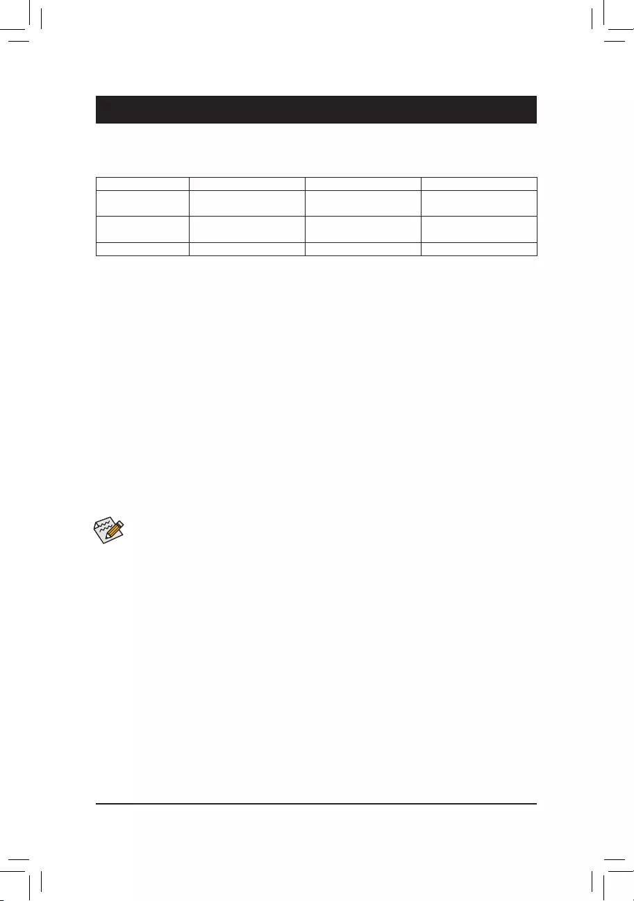
RAID Levels
RAID 0 RAID 1 RAID 10
Minimum Number of
Hard Drives ≥2 2 4
Array Capacity Number of hard drives *
Size of the smallest drive
Size of the smallest drive (Number of hard drives/2) *
Size of the smallest drive
Fault Tolerance No Yes Yes
The BIOS Setup menus described in this section may differ from the exact settings for your
motherboard. The actual BIOS Setup menu options you will see shall depend on the motherboard
you have and the BIOS version.
— 37 —
Please visit GIGABYTE’s website for details on conguring a RAID array.
Install the RAID driver and operating system
With the correct BIOS settings, you are ready to install the operating system.
Installing the Operating System
As some operating systems already include RAID driver, you do not need to install separate RAID driver during
the Windows installation process. After the operating system is installed, we recommend that you install all
required drivers from the motherboard driver disc using «Xpress Install» to ensure system performance and
compatibility. If the operating system to be installed requires that you provide additional RAID driver during the
OS installation process, please refer to the steps below:
1. Copy the Hw10 folder under the \BootDrv folder in the driver disc to your USB thumb drive.
2. Boot from the Windows setup disc and perform standard OS installation steps. When the screen requesting
you to load the driver appears, select Browse.
3. Insert the USB thumb drive and then browse to the location of the driver. The location of the drivers is as
follows:
\Hw10\RAID\x64
4. Select AMD-RAID Bottom Device rst and click Next to load the driver. Then select AMD-RAID Controller
and click Next to load the driver. Finally, continue the OS installation.
— 38 —
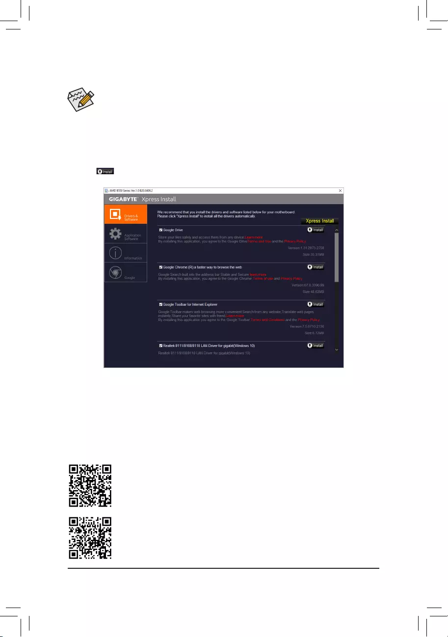
•Before installing the drivers, rst install the operating system.
•After installing the operating system, insert the motherboard driver disc into your optical drive. Click
on the message «Tap to choose what happens with this disc» on the top-right corner of the screen
and select «Run Run.exe.» (Or go to My Computer, double-click the optical drive and execute the
Run.exe program.)
«Xpress Install» will automatically scan your system and then list all of the drivers that are recommended to
install. You can click the Xpress Install button and «Xpress Install» will install all of the selected drivers. Or click
the arrow icon to individually install the drivers you need.
Please visit GIGABYTE’s website for more software information.
3-2 Drivers Installation
Please visit GIGABYTE’s website for more troubleshooting information.
— 39 —

Regulatory Notices
CAUTION:
The manufacturer is not responsible for any interference caused by unauthorized modications and/or use of unauthorized antennas. Such changes
and/or modications not expressly approved by the party responsible for compliance of this device could void the user’s authority to operate the
equipment.
RF exposure statement / Antenna Use
Further RF exposure reduction can be achieved if the product can be kept as far as possible from the user body or set the device to lower output
power if such function is available.
•Do not touch or move antenna while the unit is transmitting or receiving.
•Do not hold any component containing the radio such that the antenna is very close or touching any exposed parts of the body, especially the face
or eyes, while transmitting.
•Do not operate the radio or attempt to transmit data unless the antenna is connected; this behavior may cause damage to the radio.
United States of America, Federal Communications Commission Statement
Supplier’s Declaration of Conformity
47 CFR § 2.1077 Compliance Information
Product Name: Motherboard
Trade Name: GIGABYTE
Model Number: B550 AORUS ELITE AX V2/B550 AORUS ELITE V2
Responsible Party – U.S. Contact Information: G.B.T. Inc.
Address: 17358 Railroad street, City Of Industry, CA91748
Tel.: 1-626-854-9338
Internet contact information: https://www.gigabyte.com
FCC Compliance Statement:
This device complies with Part 15 of the FCC Rules, Subpart B, Unintentional Radiators.
Operation is subject to the following two conditions: (1) This device may not cause harmful interference, and (2) this
device must accept any interference received, including interference that may cause undesired operation.
This equipment has been tested and found to comply with the limits for a
Class B digital device, pursuant to Part 15 of the FCC Rules. These limits
are designed to provide reasonable protection against harmful interference
in a residential installation. This equipment generates, uses and can radiate
radio frequency energy and, if not installed and used in accordance with
manufacturer’s instructions, may cause harmful interference to radio
communications. However, there is no guarantee that interference will
not occur in a particular installation. If this equipment does cause harmful
interference to radio or television reception, which can be determined by
turning the equipment off and on, the user is encouraged to try to correct
the interference by one or more of the following measures:
•Reorient or relocate the receiving antenna.
•Increase the separation between the equipment and receiver.
•Connect the equipment to an outlet on a circuit different from that to
which the receiver is connected.
•Consult the dealer or an experienced radio/TV technician for help.
Notice for 5GHz
Operations in the 5.15-5.25GHz band are restricted to indoor usage
only. (For 5GHz only)
Canadian Department of Communications Statement
This digital apparatus does not exceed the Class B limits for radio
noise emissions from digital apparatus set out in the Radio Interference
Regulations of the Canadian Department of Communications. This class
B digital apparatus complies with Canadian ICES-003.
Avis de conformité à la réglementation d’Industrie Canada
Cet appareil numérique de la classe B est conforme à la norme NMB-
003 du Canada.
Canada-Industry Canada (IC) Regulatory statement
This device complies with Canadian RSS-210.
This device complies with Industry Canada license-exempt RSS
standard(s). Operation is subject to the following two conditions: (1) this
device may not cause interference, and (2) this device must accept any
interference, including interference that may cause undesired operation
of the device.
Cet appareil se conforme aux normesCanada d’Industrie de RSS
permis-exempt. L’utilisation est assujetti aux deux conditions suivantes:
(1) cet appareil ne peut pas causer d’interférences, et (2) cet appareil doit
accepter des interférences, y compris des interférences qui peuvent causer
desopérations non désirées de l’appareil.
Caution: When using IEEE 802.11a wireless LAN, this product is restricted
to indoor use due to its operation in the 5.15-to 5.25-GHz frequency
range. Industry Canada requires this product to be used indoors for the
frequency range of 5.15 GHz to 5.25 GHz to reduce the potential for
harmful interference to co-channel mobile satellite systems. High power
radar is allocated as the primary user of the 5.25-to 5.35-GHz and 5.65 to
5.85-GHz bands. These radar stations can cause interference with and/or
damage to this device. The maximum allowed antenna gain for use with
this device is 6dBi in order to comply with the E.I.R.P limit for the 5.25-to
5.35 and 5.725 to 5.85 GHz frequency range in point-to-point operation. To
comply with RF exposure requirements all antennas should be located at a
minimum distance of 20cm, or the minimum separation distance allowed
by the module approval, from the body of all persons.
Attention: l’utilisation d’un réseau sans l IEEE802.11a est restreinte à
une utilisation en intérieur à cause du fonctionnement dansla bande de
fréquence 5.15-5.25 GHz. Industry Canada requiert que ce produit soit
utilisé à l’intérieur des bâtiments pour la bande de fréquence 5.15-5.25
GHz an de réduire les possibilités d’interférences nuisibles aux canaux
co-existants des systèmes de transmission satellites. Les radars de
puissances ont fait l’objet d’une allocation primaire de fréquences dans
les bandes 5.25-5.35 GHz et 5.65-5.85 GHz. Ces stations radar peuvent
créer des interférences avec ce produit et/ou lui être nuisible. Le gain
d’antenne maximum permissible pour une utilisation avec ce produit
est de 6 dBi an d’être conforme aux limites de puissance isotropique
rayonnée équivalente (P.I.R.E.) applicable dans les bandes 5.25-5.35 GHz
et 5.725-5.85 GHz en fonctionnement point-à-point. Pour se conformer aux
conditions d’exposition de RF toutes les antennes devraient être localisées
à une distance minimum de 20 cm, ou la distance de séparation minimum
permise par l’approbation du module, du corps de toutes les personnes.»
— 40 —
Radiation Exposure Statement:
Under Industry Canada regulations, this radio transmitter may only operate
using an antenna of a type and maximum (or lesser) gain approved for
the transmitter by Industry Canada. To reduce potential radio interference
to other users, the antenna type and its gain should be so chosen that
the equivalent isotopically radiated power (e.i.r.p.) is not more than that
necessary for successful communication.
Selon les règlements de Canada d’Industrie, cet émetteur de radio peut
seulement fonctionner en utilisant une antenne du typeet de gain maximum
(ou moindre) que le gainapprouvé pour l’émetteur par Canada d’Industrie.
Pour réduire lesinterférencesradio potentiellesavec les autres utilisateurs,
le type d’antenne et son gain devraient êtrechoisis de façon à ce que la
puissance isotrope rayonnée équivalente(P.I.R.E.)ne soit pas supérieure
à celle qui estnécessaire pour une communication réussie.
European Union (EU) CE Declaration of Conformity
This device complies with the following directives: Electromagnetic
Compatibility Directive 2014/30/EU, Radio Equipment Directive (RED)
2014/53/EU, Low-voltage Directive 2014/35/EU, RoHS directive (recast)
2011/65/EU & the 2015/863 Statement.
This product has been tested and found to comply with all essential
requirements of the Directives
European Union (EU) RoHS (recast) Directive 2011/65/EU & the
European Commission Delegated Directive (EU) 2015/863 Statement
GIGABYTE products have not intended to add and safe from hazardous
substances (Cd, Pb, Hg, Cr+6, PBDE, PBB, DEHP, BBP, DBP and DIBP).
The parts and components have been carefully selected to meet RoHS
requirement. Moreover, we at GIGABYTE are continuing our efforts to
develop products that do not use internationally banned toxic chemicals.
European Union (EU) Community Waste Electrical & Electronic
Equipment (WEEE) Directive Statement
GIGABYTE will fulll the national laws as interpreted from the 2012/19/
EU WEEE (Waste Electrical and Electronic Equipment) (recast) directive.
The WEEE Directive species the treatment, collection, recycling and
disposal of electric and electronic devices and their components. Under
the Directive, used equipment must be marked, collected separately, and
disposed of properly.
WEEE Symbol Statement
The symbol shown below is on the product or on its
packaging, which indicates that this product must not be
disposed of with other waste. Instead, the device should be
taken to the waste collection centers for activation of the
treatment, collection, recycling and disposal procedure.
For more information about where you can drop off your waste equipment
for recycling, please contact your local government ofce, your household
waste disposal service or where you purchased the product for details of
environmentally safe recycling.
End of Life Directives-Recycling
The symbol shown below is on the product or on its packaging,
which indicates that this product must not be disposed of with
other waste. Instead, the device should be taken to the waste
collection centers for activation of the treatment, collection,
recycling and disposal procedure.
Déclaration de Conformité aux Directives de l’Union européenne (UE)
Cet appareil portant la marque CE est conforme aux directives de l’UE
suivantes: directive Compatibilité Electromagnétique 2014/30/UE, directive
RED (équipements radioélectriques) 2014/53/UE, directive Basse Tension
2014/35/UE et directive RoHS II 2011/65/UE. La conformité à ces directives
est évaluée sur la base des normes européennes harmonisées applicables.
European Union (EU) CE-Konformitätserklärung
Dieses Produkte mit CE-Kennzeichnung erfüllen folgenden EU-Richtlinien:
EMV-Richtlinie 2014/30/EU, Richtlinie RED (Funkanlagen) 2014/53/EU,
Niederspannungsrichtlinie 2014/30/EU und RoHS-Richtlinie 2011/65/
EU erfüllt. Die Konformität mit diesen Richtlinien wird unter Verwendung
der entsprechenden Standards zurEuropäischen Normierung beurteilt.
CE declaração de conformidade
Este produto com a marcação CE estão em conformidade com das
seguintes Diretivas UE: Diretiva de equipamentos de rádio 2014/53/EU,
Diretiva Baixa Tensão 2014/35/EU; Diretiva CEM 2014/30/EU; Diretiva
RSP 2011/65/UE. A conformidade com estas diretivas é vericada
utilizando as normas europeias harmonizadas.
CE Declaración de conformidad
Este producto que llevan la marca CE cumplen con las siguientes
Directivas de la Unión Europea: Directiva EMC 2014/30/EU, Directiva de
equipos radioeléctricos 2014/53/EU, Directiva de bajo voltaje 2014/35/EU,
Directiva RoHS (recast) 2011/65/EU. El cumplimiento de estas directivas
se evalúa mediante las normas europeas armonizadas.
Dichiarazione di conformità CE
Questo prodotto è conforme alle seguenti direttive: Direttiva sulla
compatibilità elettromagnetica 2014/30/UE, Direttiva sulle apparecchiature
radio (RED) 2014/53/UE, Direttiva sulla bassa tensione 2014/35/UE,
Direttiva RoHS (rifusione) 2011/65/UE. Questo prodotto è stato testato e
trovato conforme a tutti i requisiti essenziali delle Direttive.
Contact point for EU based customers
G.B.T. Technology Trading GmbH
Am Stadtrand 63, 22047 Hamburg, Germany
tel: +49-40-25 33 040
— 41 —
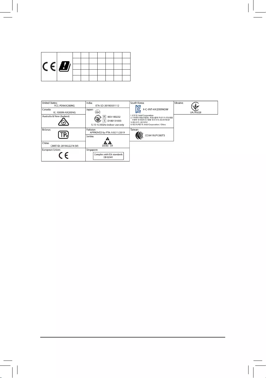
European Community Directive RED Directive Compliance Statement:
This equipment is suitable for home and ofce use in all the European Community Member States and EFTA Member States.
The low band 5.15 -5.35 GHz is for indoor use only for the countries listed in the table below:
AT BE BG CH CY CZ DE
DK EE EL ES FI FR HR
HU IE IS IT LI LT LU
LV MT NL PL PT RO SE
SI SK TR UK
Wireless module country approvals:
Wireless module model name: AX200NGW
Wireless module manufacturer: Intel® Corporation
Korea Wireless Statement:
5.15 — 5.35 GHz 대역에서의 작동은 실내로。
Japan Wireless Statement:
5.15 GHz帯 ~ 5.35 GHz帯: 屋内のみの使用。
Taiwan NCC Wireless Statements / 無線設備警告聲明:
低功率電波輻射性電機管理辦法
第十二條: 經型式認證合格之低功率射頻電機,非經許可,公司、商號或使用者均不得擅自變更頻率、加大功率或變更原設
計之特性及功能。
第十四條: 低功率射頻電機之使用不得影響飛航安全及干擾合法通信;經發現有干擾現象時,應立即停用,並改善至無干擾
時方得繼續使用。前項合法通信,指依電信法規定作業之無線電通信。低功率射頻電機須忍受合法通信或工業、
科學及醫療用電波輻射性電機設備之干擾。
在5.25-5.35秭赫頻帶內操作之無線資訊傳輸設備,限於室內使用。
— 42 —

— 43 —
Contact Us
GIGA-BYTE TECHNOLOGY CO., LTD.
Address: No.6, Baoqiang Rd., Xindian Dist., New Taipei City 231, Taiwan
TEL: +886-2-8912-4000, FAX: +886-2-8912-4005
Tech. and Non-Tech. Support (Sales/Marketing) : https://esupport.gigabyte.com
WEB address (English): https://www.gigabyte.com
WEB address (Chinese): https://www.gigabyte.com/tw
•GIGABYTE eSupport
To submit a technical or non-technical (Sales/Marketing) question, please link to:
https://esupport.gigabyte.com
— 44 —
Материнская плата Gigabyte B550 AORUS ELITE V2, SocketAM4, AMD B550, ATX, Ret
Нет в наличии
Последний раз товар был 26 мая
- Форм-фактор: ATX
- Сокет: SocketAM4; чипсет: AMD B550
- Память: 4х DDR4; частотой до 3200 МГц
- Слоты: PCI-E 4.0 x16 х 1, PCI-E 3.0 x16 х 2, PCI-E x1 х 1
- Разъемы: M.2 х 2, Display Port х 1, HDMI х 1
- Сеть: 2.5Gigabit
Появились вопросы о товаре?
- Форм-фактор: ATX
- Сокет: SocketAM4; чипсет: AMD B550
- Память: 4х DDR4; частотой до 3200 МГц
- Слоты: PCI-E 4.0 x16 х 1, PCI-E 3.0 x16 х 2, PCI-E x1 х 1
- Разъемы: M.2 х 2, Display Port х 1, HDMI х 1
- Сеть: 2.5Gigabit
Появились вопросы о товаре?
Нет в наличии
Последний раз товар был 26 мая
Нет в наличии
Последний раз товар был 26 мая
Содержание
- Тест и обзор: Gigabyte B550 AORUS Pro (AC) — материнская плата среднего класса с обилием USB
- Страница 1: Тест и обзор: Gigabyte B550 AORUS Pro (AC) — материнская плата среднего класса с обилием USB
- Технические характеристики
- Комплект поставки
- Обзор материнской платы Gigabyte B550m Aorus Pro-P
- Введение
- Техническое описание
- Упаковка и комплектация
- Внешний вид
- Особенности
- Подсистема питания и радиаторы
- Система хранения
- Встроенный звук
- Тестирование
- Заключение.
- Настройка BIOS на материнских платах Gigabyte
- Видео инструкция
- Настраиваем БИОС Гигабайт
- Настройки RAM
- Параметры GPU
- Настройка вращения кулеров
- Оповещения о перегреве
- Настройки загрузки
- Сохранение настроек
- Обзор материнской платы GIGABYTE B550 AORUS PRO: встречаем новый AMD B550
- Характеристики материнской платы GIGABYTE B550 AORUS Elite V2
- Общие характеристики
- Процессор
- Чипсет
- BIOS/EFI
- Оперативная память
Тест и обзор: Gigabyte B550 AORUS Pro (AC) — материнская плата среднего класса с обилием USB
16.07.2020 в 21:55
Страница 1: Тест и обзор: Gigabyte B550 AORUS Pro (AC) — материнская плата среднего класса с обилием USB
Мы уже протестировали ASUS ROG Strix B550-E Gaming, первую материнскую плату на чипсете AMD B550, ориентированную на верхний сегмент массового рынка. Gigabyte B550 AORUS Pro стоит дешевле, но оснащение все равно можно назвать вполне достойным. Посмотрим, как материнская плата покажет себя на практике.
Gigabyte со своими материнскими платами AORUS довольно активно поддержала платформу AMD, в том числе и новый чипсет B550 для массового рынка, который призван активно продвигать стандарт PCIe 4.0 среди пользователей. Если ограничиться моделями ATX, то флагманом будет B550 AORUS Master, потом идет материнская плата Elite. За ней следует тестируемая модель B550 AORUS Pro, которая представлена и в варианте с модулем WLAN AC.
Gigabytes B550 AORUS Pro использует матовую черную PCB с габаритами ATX. Радиаторы и кожух панели ввода/вывода черные с серебристыми вставками, на кожухе хорошо видна надпись «Team up Fight on». А на радиаторе PCH красуется логотип AORUS.
Технические характеристики
Ниже приведены технические спецификации Gigabyte B550 AORUS Pro (AC):
| Формат материнской платы | ATX |
|---|---|
| Производитель и модель |
Gigabyte B550 AORUS Pro (AC) |
| Сокет CPU | AM4 (для Matisse) |
| Разъёмы питания | 1x 24-конт. ATX 1x 8-конт. EPS12V |
| Фазы/дроссели | 15 (14x CPU, 1x RAM) |
| Розничная цена | Gigabyte B550 AORUS Pro: от 15.200 ₽ Gigabyte B550 AORUS Pro AC: от 16.700 ₽ |
| Сайт производителя | Gigabyte B550 AORUS Pro Gigabyte B550 AORUS Pro AC |
| Функции чипсета/CPU | |
| Чипсет | AMD B550 |
| Память и тип | 4x DDR4 (два канала), мкас. 5.200 МГц |
| Подсистема памяти | Макс. 128 GB RAM UDIMM, поддержка ECC |
| SLI / CrossFire | — |
| Встроенные функции | |
| PCI Express | 1x PCIe 4.0 x16 (электрически x16) через CPU 2x PCIe 3.0 x16 (электрически x4/x2, 1x общие ресурсы) через AMD B550 2x PCIe 3.0 x1 через AMD B550 |
| PCI | — |
| Накопители | 6x SATA 6 Гбит/с через AMD B550 1x M.2 PCIe 4.0 x4 через CPU (M-Key) 1x M.2 PCIe 3.0 x4 через AMD B550 (M-Key, общие ресурсы) |
| USB | CPU: 3x USB 3.2 Gen1 (5 Гбит/с, Type A, 3x внешних) 1x USB 3.2 Gen2 (10 Гбит/с, Type A, 1x внешний) |
Комплект поставки
- Руководство материнской платы, DVD с драйверами и программами
- Многоязычное руководство по установке
- Четыре кабеля SATA
- Удлинитель RGB
- Разные наклейки Gigabyte AORUS
- G-Connector
- Две кабельные затяжки
- Наклейка на корпус Gigabyte AORUS
Gigabyte приложила вместе с платой все основные аксессуары. G-Connector облегчит подключение портов фронтальной панели корпуса, две кабельные затяжки тоже пригодятся. С вариантом AC прилагается и антенна WLAN.
Подписывайтесь на группы Hardwareluxx ВКонтакте и Facebook, а также на наш канал в Telegram (@hardwareluxxrussia).
Мы рекомендуем ознакомиться с нашим FAQ по выбору материнской платы, в котором мы ответим на многие вопросы, возникающие у пользователей: какой формат предпочесть? На каком сокете и чипсете? Какие интерфейсы должны быть на материнской плате? Имеет ли смысл доплачивать за дополнительные функции? И что нужно настраивать в BIOS (UEFI)? Конечно, мы ответим и на многие другие вопросы.
Мы рекомендуем ознакомиться с нашим руководством по выбору материнских плат AMD, где мы рекомендуем лучшие модели за свою цену.
Тест и обзор: Gigabyte B550 AORUS Pro (AC) — материнская плата среднего класса с обилием USB
Функции и раскладка
Источник
Обзор материнской платы Gigabyte B550m Aorus Pro-P
Введение
Я не являюсь профессиональным обзорщиком, у меня нет профессионального фотооборудования, тепловизора, и так далее. Но недавно в руках у меня оказалась плата B550, которую мне было интересно проанализировать и распробовать. Перед Новым Годом я спонтанно купил Ryzen 5950х и вставил его в плату Asrock x570 Taichi, которую выдернул из машины в офисе. Взамен решил взять в офис что-то более бюджетное. Выбор пал на Gigabyte B550m Aorus Pro-P. По меркам b550 чипсета эта плата если и не эконом-класса, то явно имеет ценник сильно ниже среднего. При этом ее система питания выглядит достаточно серьезной, а оснащение соответствует среднему и даже выше классу для плат на чипсетах b450/x470/z370.
Некоторые называют ее народной — ее цена колебалась последнее время между 9 и 10 тысячами рублей, за эти же деньги у других производителей предлагается откровенный эконом класс, с минимальными VRM, радиаторами и функциями. За цены более низкой категории (до 8 тысяч рублей) предлагаются в основном откровенно слабые платы, в которые нестрашно вставлять только какие-нибудь 4х ядерники. Gigabyte B550m Aorus Pro-P — оптимизированная версия Gigabyte B550m Aorus Prо, вышедшая в октябре 2020го. Ее отличие от версии без -P — переработанная (и, как мне кажется, в лучшую сторону) система питания.
Давайте посмотрим насколько она хороша и есть ли какой-то подвох.
Техническое описание
Чипсет + Концентратор USB 2.0:
4 порта USB 2.0/1.1 на задней панели
PCIe-линии чипсета:
1 порт USB Type-C™ на задней панели, совместим с устройствами USB 3.2 Gen 2
1 порт USB 3.2 Gen 2 (Type-A разъем красного цвета на задней панели)
2 порта USB 3.2 Gen 1, доступны при подключении к USB-разъему на материнской плате
4 порта USB 2.0/1.1 (доступны при подключении к USB-разъему на материнской плате)
Процессор:
4 порта USB 3.2 Gen 1 на задней панели
Упаковка и комплектация
Стандартная компактная коробка под mATX из толстого картона с описанием основных преимуществ модели:
Плата внутри коробки зафиксирована надежно.
Комплектация максимально скромная, как у типичной бюджетной модели:
- Сама плата
- Диск с ПО
- Инструкция
- SATA-кабель
- Сувенирная Наклейка
Внешний вид
Посмотрим на плату сверху:
Плата почти полностью выдержана в черных и темно-серых тонах, форма радиатора и крышки задней панели напоминает архитектуру инопланетян из серии Half-Life или модные гипсовые стеновые панели. Нужно отметить, что крышка задней панели сделана из очень толстого пластика, и сидит практически без зазоров. На плате практически нет подсветки и это ее преимущество — китчевое обилие RGB выходит из моды, а его отсутствие немного, но снижает цену платы. В целом плата смотрится органично и стильно хоть в игровой сборке, хоть в офисной.
Тыльная сторона платы не несет никаких функциональных элементов, кроме крепления кулера и болтов. Дополнительного бэкплейта не предусмотрено.
Задняя панель предустановлена, что очень хорошо для бюджетной платы — упрощает установку и убирает риск погнуть накладную панельку. Кроме того она весьма качественно закреплена и стильно выглядит.
Что касается общего впечатления от качества исполнения платы — то каких-то претензий назвать нельзя. Текстолит не изгибается и ощущается достаточно толстым (для сравнения на моей Asrock Taichi он ощущается более хлипким). Острые элементы пайки или креплений не обнаружены. Все элементы установлены достаточно аккуратно, за исключением пары дросселей, но такое я видел даже на супертоповой Asus Zenith Extreme Alpha.
Особенности
- Что можно сразу отнести к плюсам — обилие USB выходов на задней панели. В этом отношении она выбивается из бюджетного сегмента — тут их аж 10 штук. Для меня, например, их постоянно не хватает — подключены мышь, клавиатура, принтер, VR гарнитура, фотосканер, микроскоп, токен подписи, контроллер умного дома. Если бы на моей Asrock не было встроенного wi-fi и bluetooth, то выткать уже было бы некуда.
- Еще один маленький плюс, нехарактерный для бюджетных плат — слоты для памяти защелкиваются с обеих сторон, что упрощает установку и замену памяти.
- Приятная мелочь — основные разъемы для подключения шлейфов (usb, audio, прочее) подписаны изнутри большими белыми буквами, что ускоряет сборку.
- Еще плюс — возможность обновлять BIOS через флешку без включения системы
- При фактическом отсутствии подсветки самой платы есть 4 разъема для подключения RGB подсветки, в том числе 2 addressable RGB.
- Существенный для меня эргономический минус — это расположение PCI-E x1 порта:
Он идет вплотную к первому x16 порту, и фактически, после установки видеокарты оказывается недоступен. Да, так сделано у большинства плат B550 и не только, но есть исключение: Asus TUF: Здесь он находится выше слота под видеокарту. Это позволяет без особых проблем вставить звуковую, сетевую или wi-fi карту, что может быть весьма востребованным для некоторых пользователей, с учетом, что например, встроенного wi-fi нет, а хорошие USB приемники стоят дороже pci-e. Берите пример с TUF.
- Еще один минус — отсутствие POST-кодов и диодов проверки. Но это совершенно предсказуемо для платы такого сегмента.
Подсистема питания и радиаторы
Перейдем к самому интересному. Неужели в одной из самых дешевых B550 плат стоит достойная VRM?
Снимем радиаторы и крышку:
Доп. разъем для питания процессора — 8-контактный. Этого хватит для работы с любым Ryzen в стоке, но для разгона хотелось бы 12-16 контактов. Перед тем как продолжим разбирать систему питания, давайте взглянем на радиаторы:
Они реально огромны для mATX платы. Тот, что накрывает западную часть — пожалуй один из самых массивных среди всех B550:
При этом контактируют радиаторы только с мосфетами, не закрывая дроссели. Странное решение, учитывая размер радиатора.
Управляет фазами питания чип RAA229004 производства Renesas (которая купила Intersil). Работает он в режиме 5+2: 5 фаз на ядра процессора и 2 фазы на SOC. К сожалению, найти какую-то подробную информацию по RAA229004 найти не удается. При этом он стоит в половине (причем достойной) плат B550. Можем предположить, что это адаптированный под AMD контроллер, так как не удалось найти его в платах под Intel.
Схема питания реализована следующим образом:
Мы имеем 5 фаз с распараллеленными контурами: по 2 DrMOS на фазу (соответственно удвоятся и дросселя). В предыдущей версии B550m Aorus Pro (без -P) были удвоители, здесь их убрали, зато поставили гораздо более совершенные Driver + MOSFet’ы : Vishay SiC651 . Это достаточно новый и технологичный DrMOS. Во-первых, у него есть термосенсор и широкий набор защит, во-вторых, высокая частота переключения (2 МГц). Не вдаваясь в электротехнические подробности отметим, что, во-первых, такой DrMOS не даст критически перегреться контуру и сведет к минимуму риски прогаров. Во-вторых, он очень быстро способен перестроить параметры преобразованного тока, что будет полезно при использовании Load-line calibration высоких уровней — после снятия нагрузки будет больше шансов предотвратить нежелательный скачек напряжения (опять же это еще зависит от контроллера, про который мы мало что знаем). Для сравнения — у той же более дорогой Asus TUF B550 DrMOS куда как более простые, с минимальной функциональностью — SiC639. Заявленная максимальная сила тока для SiC651 равна 50 Амперам, что приводит к теоретическому порогу мощности всего контура VRM под 500 ватт. На деле это число можно уменьшить вдвое, но все равно результат будет внушителен.
Конденсаторы — 5k, твердотельные, очевидно — тайваньские:
Итак, мы имеем в теории очень хорошую VRM, которая должна легко обуздать в стоке любой из am4 Ryzen’ов и позволить определенный разгон. Кто-то скажет, что пять истинных фаз этого мало — к вам у меня встречный вопрос — какое преимущество даст 10 истинных фаз для Zen2 и Zen3 при условии что рассмотренная выше VRM запросто выдерживает большую потребляемую мощность (закон Джоуля-Ленца не отменял).
Система хранения
Система хранения представлена 4-мя SATA разъемами и двумя m.2 разъемами, позволяющими использовать как NVMe так и SATA m.2 накопители. Верхний m.2 разъем накрыт алюминиевым радиатором с декоративным оребрением и терпмопрокладкой:
из SATA-устройств можно сформировать RAID 0,1,10 средствами чипсета B550.
Встроенный звук
Встроенный звуковой кодек — Realtek ALC 1200. По качеству звука (я использую наушники Plantronics Voyager 8200 UC подключенные по проводу при тестировании) я бы расположил аккурат посередине между тем, что выдавала Aorus Elite B450 и Asus Zenith Extreme Alpha c «премиальным» звуком из коробки. Это крайне субъективное суждение, но что есть. Для меня разница с ALC 887 есть, и, для хороших наушников, я бы сказал она будет принципиальной. При этом не видно, что на плате какой-то мощный набор конденсаторов и вряд-ли есть толковый усилитель.
Стандартный BIOS Gigabyte и очень похожий на все B550 BIOS’ы, за исключением топовых оверклокерских плат.
Присутствуют все tweak-функции и мониторинг.
Первыми в списке разгонными параметрами установлены селекторы частот BCLK и множителя, что, вообще говоря — дело вкуса, но зная поведение zen2/zen3 я бы предпочел сразу встретить простой селектор конечной частоты и VCore. Присутствует возможность выставлять ручной оффсет напряжений как процессора так и SoC, причем по-традиции Gigabyte он назван Dynamic VCore, что на мой взгляд слегка вводит в заблуждение.
Дополнительные настройки производительности процессора довольно стандартны — присутствует возможность включать/отключать SVM, контролировать количество активный ядер, выбирать рабочую CCD, контролировать возможность выбирать предпочтительные ядра.
Интересно наличие аж 9 уровней LLC, хотя из них только 6 осмысленные. При этом первые 3 вызывают путаницу — как отличить Normal от Standard? Явно непродуманное именование.
Присутствует стандартный регулировщик оборотов вентиляторов. При этом мною не было замечена возможность плавной перестройки частот вращения, зато есть возможность настроить предупреждение о высоких температурах и выходе из строя вентилятора. У меня не было бипера, чтобы проверить.
Из нестандартных вещей есть средство проверки nvme дисков, оно мне помогло, когда отваливалась nvme, из-за того, что в Ubuntu был настроен энергосберегающий режим (система явно делается под ноутбуки).
Тестирование
Плата тестировалась в конфигурации:
- Процессор Ryzen 3900x
- Блок питания: Cougar GX-F 750
- Кулер: Be Quiet! Dark Rock 4
- 32 и 64 Гб памяти 2666-19-19
Тестирование было в стоковом режиме и с небольшим увеличением лимитов (PPT=160, TDC=105, EDC=160) — уйти куда-то выше у меня не позволило охлаждение и отсутствие прикладного опыта разгона Zen2.
Система с процессором и кулером (Be Quiet Dark Rock 4):
Совокупно прогнав Cinebench минут 30 температуры VRM по датчику материнской платы ни разу не превысили 40 градусов в стоке и с небольшим PBO.
Замерив с помощью пирометра я не увидел тоже сильных отклонений. На радиаторе температура была не более 34 градусов. На дросселях максимум был 44 градуса. Как мне кажется — отличный результат.
Заключение.
Gigabyte B550m Aorus Pro-P против других B550 плат:
Здесь я считаю данную плату очень достойным выбором за разумные деньги (от 9 до 10 тысяч), с совершенно адекватным VRM, который выдержит любой Райзен в стоковом режиме и, пожалуй, умеренный разгон. Стоит ли на ней разгонять старшие процессоры, на которых тепловыделение может достигнуть более 250 ватт — не думаю, хотя мне не удалось полноценно протестировать. Есть множество других, более подходящих под эти цели плат, с которыми вы не будете думать как же там нагрелся этот 8-пиновый разъем питания процессора. Если вы задумываете брать Zen2, то данная плата — отличный выбор, так как разгон Zen2 дело малоперспективное. Для Zen3 — уже вопрос, так как его разгон дает прирост в профессиональных приложениях под 20%.
Gigabyte B550m Aorus Pro-P против B450 плат:
Тут я считаю так — если у вас уже есть B450 и вы рассматриваете 6-8 ядерные процессоры, то смысла рассматривать Aorus Pro-P скорее нет. Но вот брать новую B450 за условные 8 тысяч рублей, экономя на нормальном VRM, звуке, ограничивая разгон памяти — я не вижу смысла. Кроме того, Aorus Pro-P будет вполне нормальной платформой и под 12-16 ядерные процессоры в стоке.
Так есть ли подводные камни?
Я не обнаружил. Да, для b550 это кажется, оптимальный выбор. Конечно, нужно обкатать систему полгода, посмотреть стабильность и надежность на длинных дистанциях, и тогда вернуться с расширенным мнением.
Источник
Настройка BIOS на материнских платах Gigabyte

Видео инструкция
Настраиваем БИОС Гигабайт
Первое, с чего стоит начать процесс настройки – вход в режим низкоуровневого управления платой. На современных «материнках» указанного производителя за вход в БИОС отвечает клавиша Del. Её следует нажимать в момент после включения компьютера и появления заставки.
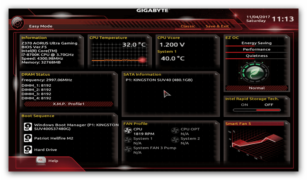
После загрузки в BIOS вы можете наблюдать следующую картину.
Как видите, производитель использует UEFI, как более безопасный и удобный для пользователя вариант. Вся инструкция далее будет ориентирована именно на UEFI-вариант.
Настройки RAM
Первое, что нужно сконфигурировать в параметрах БИОСа – тайминги оперативной памяти. Из-за неправильно установленных настроек компьютер может работать некорректно поэтому внимательно следуйте инструкции далее:
- Из главного меню перейдите к параметру «Advanced Memory Settings», расположенному на вкладке «M.I.T».
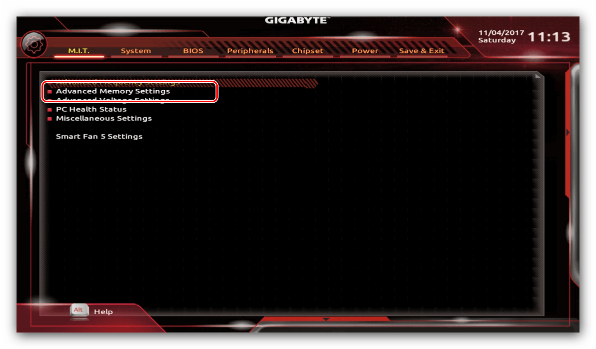
В нём перейдите к опции «Extreme Memory Profile (X.M.P.)».
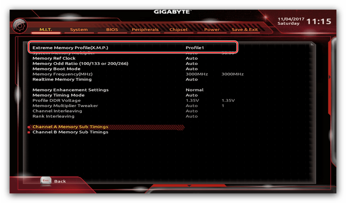
Тип профиля следует выбирать исходя из типа установленной RAM. Например, для DDR4 подойдёт вариант «Profile1», для DDR3 – «Profile2».
Также доступны опции для любителей разгона – можно вручную изменить тайминги и вольтаж для более быстрой работы модулей памяти.
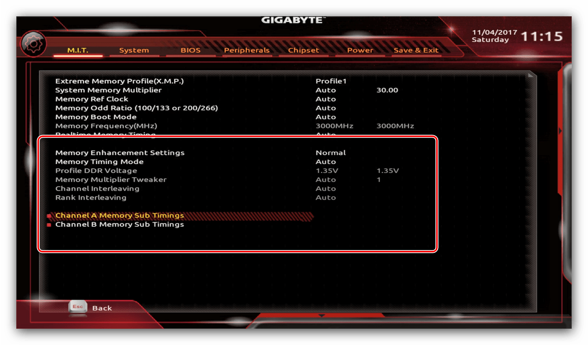
Параметры GPU
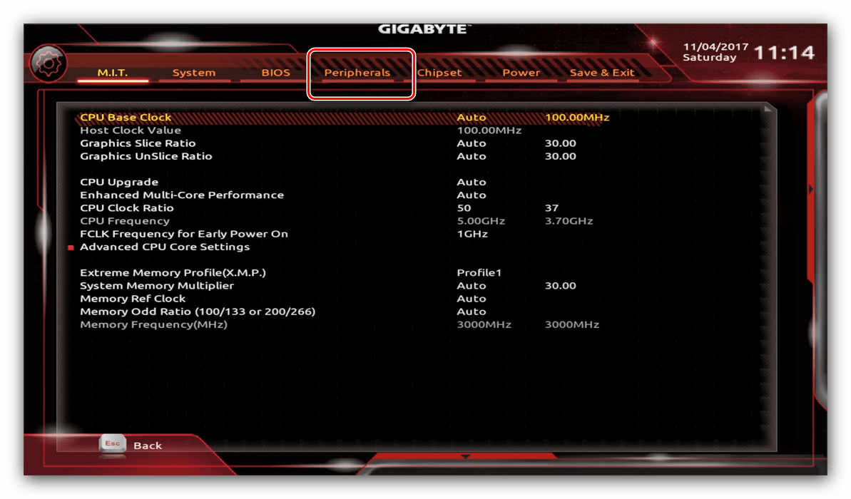
Через UEFI BIOS плат Gigabyte можно настроить работу компьютера с видеоадаптерами. Для этого перейдите на вкладку «Peripherals».
- Самой важной опцией здесь является «Initial Display Output», позволяющая установить основной используемый графический процессор. Если на компьютере на момент настройки нет выделенного GPU, следует выбрать вариант «IGFX». Для выбора дискретной видеокарты установите «PCIe 1 Slot» или «PCIe 2 Slot», зависит от порта, к которому подключен внешний графический адаптер.
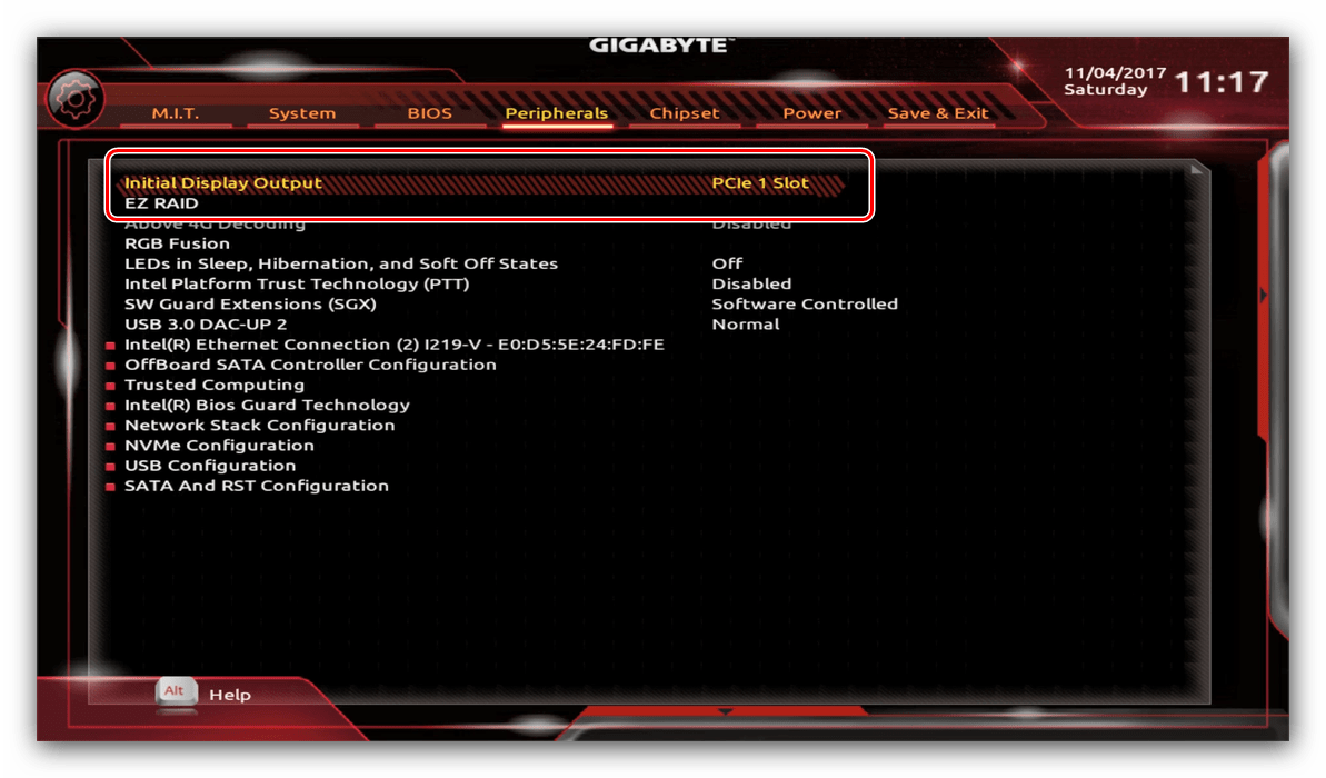
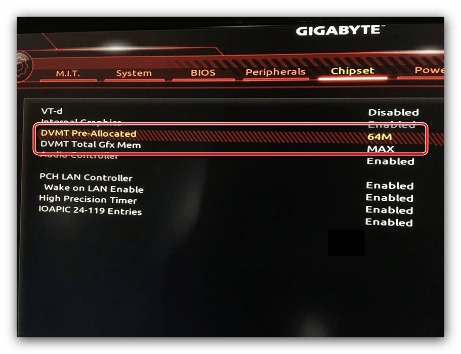
Настройка вращения кулеров
- Нелишним также будет сконфигурировать скорость вращения системных вентиляторов. Для этого перейдите воспользуйтесь опцией «Smart Fan 5».
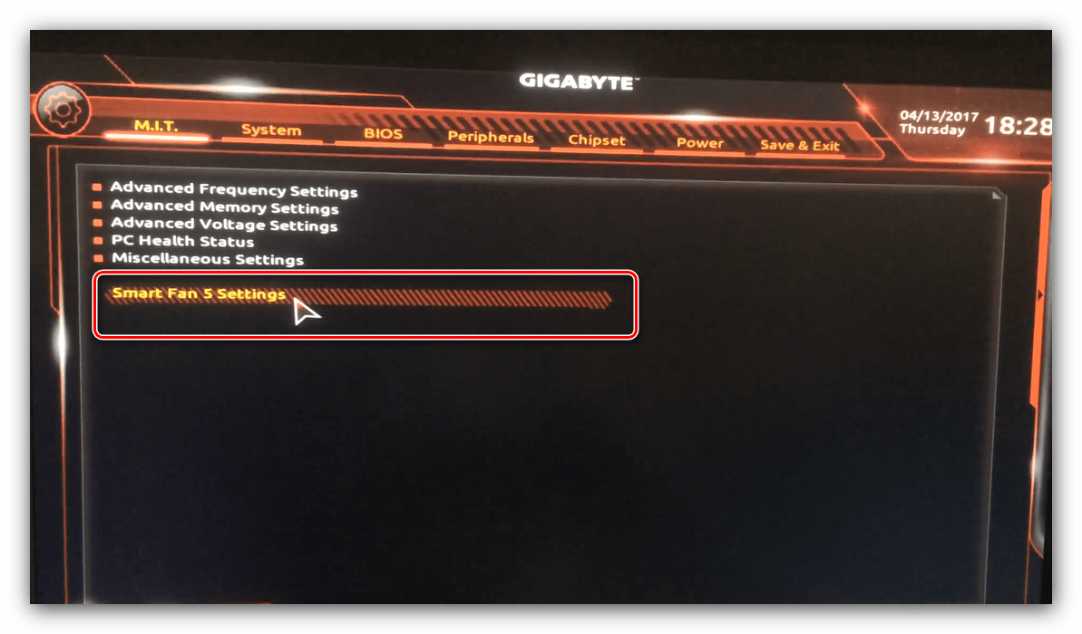
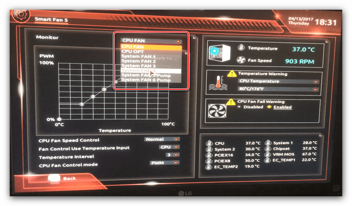
Скорости вращения каждого из них стоит установить в положение «Normal» – это обеспечит автоматический режим работы в зависимости от нагрузки.
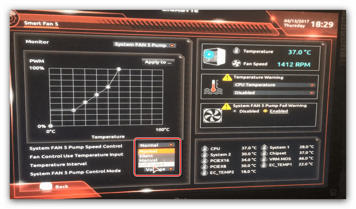
Можно также настроить режим работы кулера вручную (вариант «Manual») или выбрать минимально шумный, но обеспечивающий наихудшее охлаждение (параметр «Silent»).
Оповещения о перегреве
Также в платы рассматриваемого производителя встроено средство защиты компонентов компьютера от перегрева: при достижении порогового значения температуры пользователь получит оповещение о необходимости выключения машины. Настроить отображение этих уведомлений можно в разделе «Smart Fan 5», упомянутом на предыдущем этапе.
- Нужные нам опции расположены в блоке «Temperature Warning». Здесь потребуется вручную определить максимально допустимое значение температуры процессора. Для CPU с низким тепловыделением достаточно выбрать значение в 70 °C, а если TDP у процессора высокий, то 90 °C.
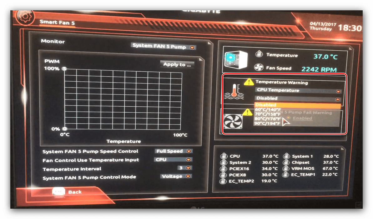
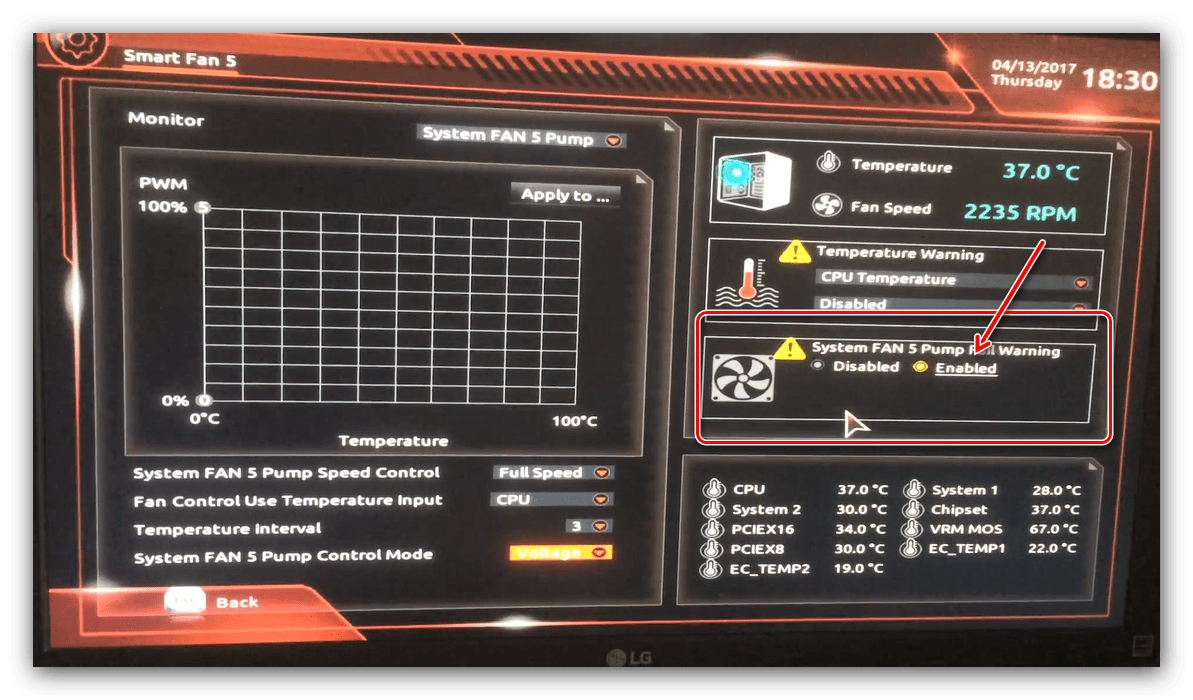
Настройки загрузки
Последние важные параметры, которые следует настроить – приоритет загрузки и включение режима AHCI.
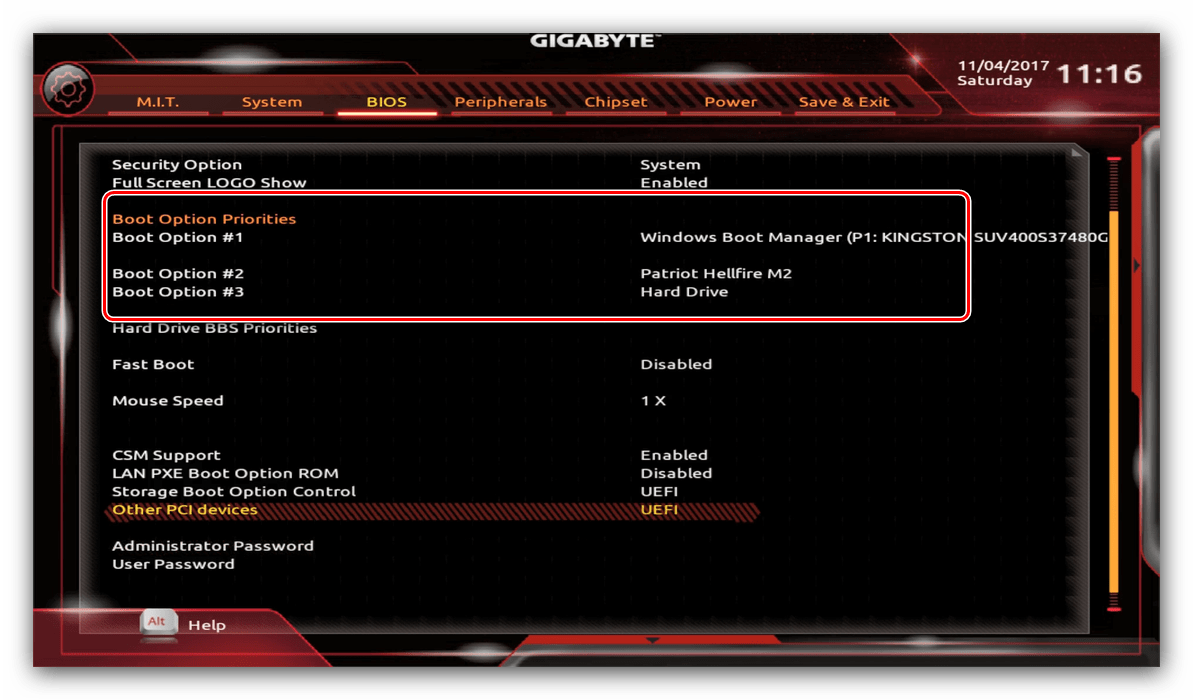
- Зайдите в раздел «BIOS Features» и воспользуйтесь опцией «Boot Option Priorities».
Здесь выберите нужный загрузочный носитель. Доступны как обычные жесткие диски, так и твердотельные накопители. Также можно выбрать флешку или оптический диск.
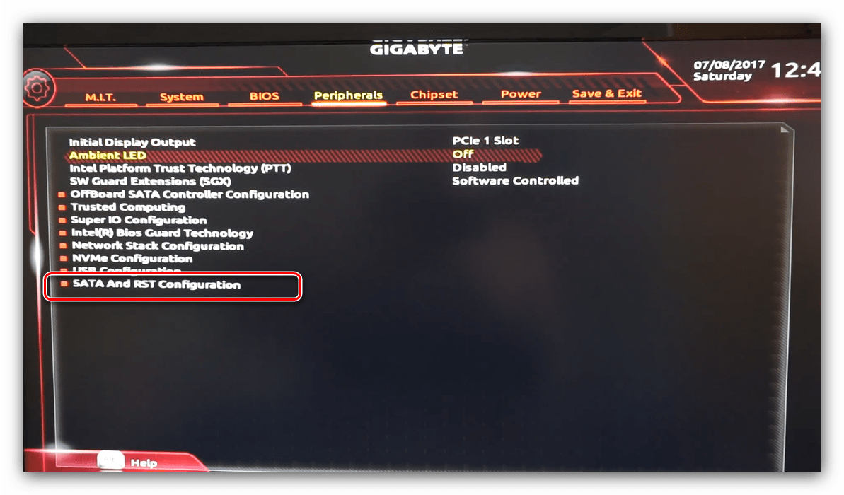
Сохранение настроек
- Для сохранения введённых параметров воспользуйтесь закладкой «Save & Exit».
Сохранение параметров происходит после нажатия на пункт «Save & Exit Setup».
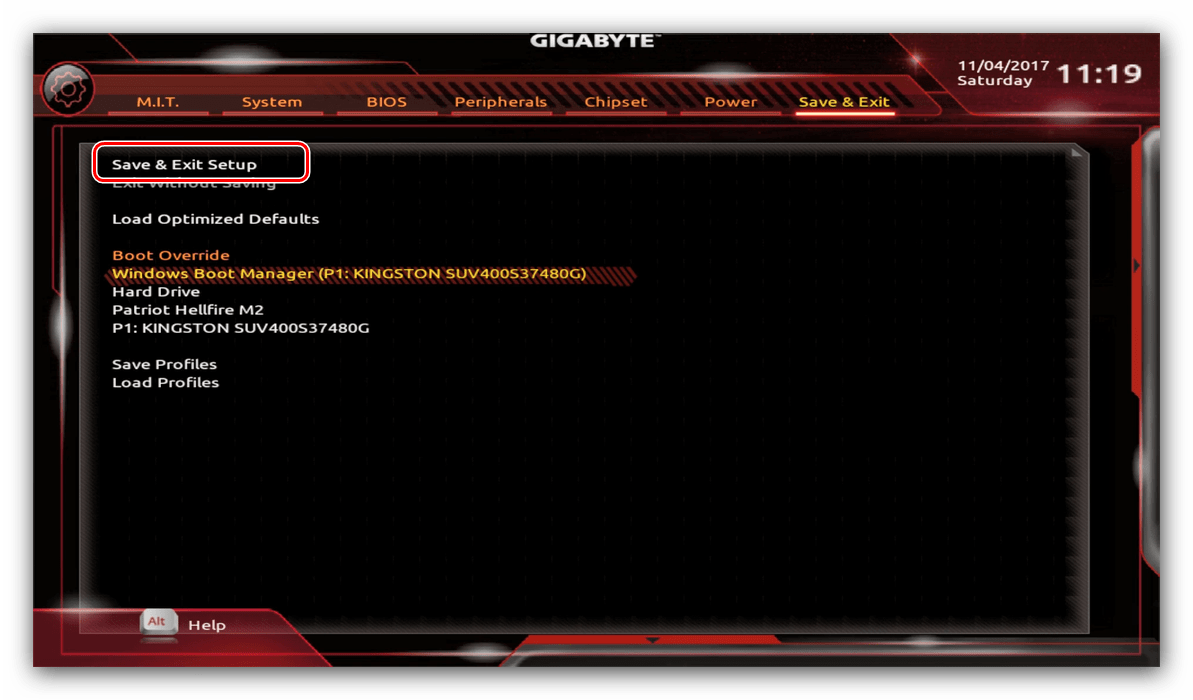
Также можно выйти без сохранения (если не уверены, что ввели всё правильно), используйте опцию «Exit Without Saving», или сбросить настройки БИОС к заводским, за что отвечает вариант «Load Optimized Defaults».
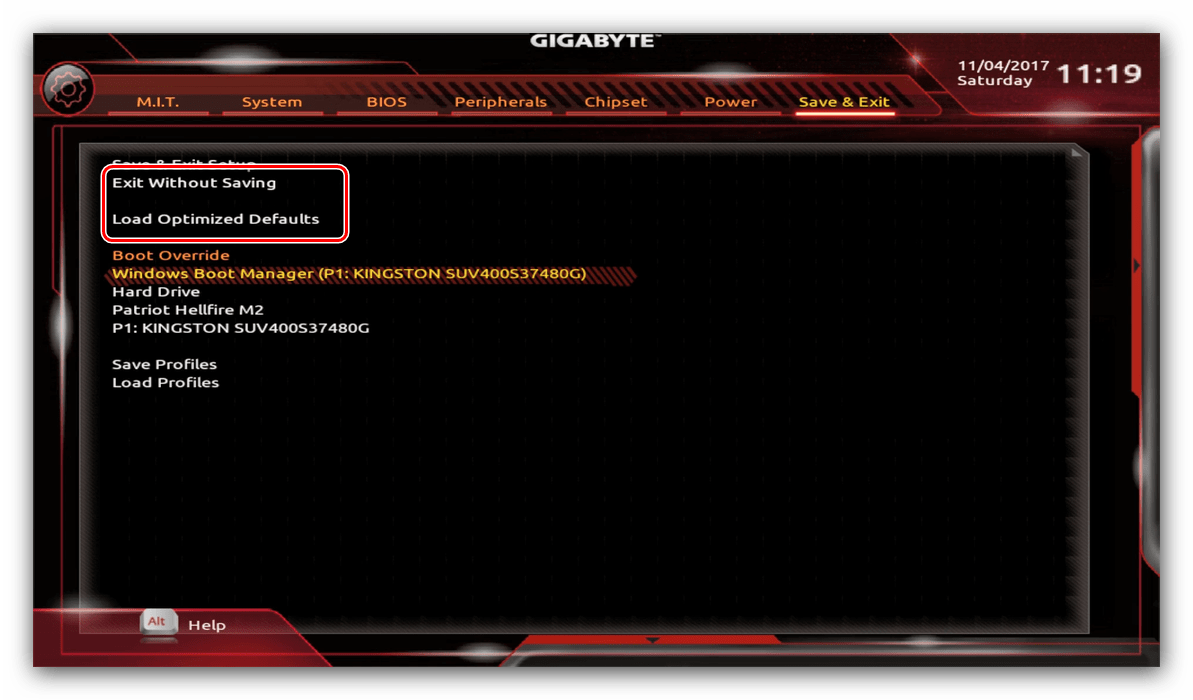
Таким образом мы закончили настройку основных параметров BIOS на материнской плате Gigabyte.
Мы рады, что смогли помочь Вам в решении проблемы.
Помимо этой статьи, на сайте еще 11905 инструкций.
Добавьте сайт Lumpics.ru в закладки (CTRL+D) и мы точно еще пригодимся вам.
Отблагодарите автора, поделитесь статьей в социальных сетях.
Опишите, что у вас не получилось. Наши специалисты постараются ответить максимально быстро.
Источник
Обзор материнской платы GIGABYTE B550 AORUS PRO: встречаем новый AMD B550
Если вы вдруг забыли, то мы напомним, что еще в мае 2019 года состоялся анонс третьего поколения процессоров AMD Ryzen и нового флагманского чипсета AMD X570. Спустя год AMD наконец-то представила долгожданный чипсет для массового сегмента – AMD B550.
По сравнению с предшественником AMD B450, новый набор системной логики получил поддержку PCI Express 4.0. Но собственных линий этого стандарта у него нет, он лишь позволяет 20 процессорным линиям работать в их родном режиме для обслуживания видеокарты и M.2 SSD. Вторым ключевым новшеством стала поддержка мультиграфических связок, которая ранее была уделом исключительно флагманских чипсетов. Третья инновация заключается в том, что четыре процессорных порта USB 3.2 Gen 2 могут работать в своем родном режиме, а не в режиме USB 3.2 Gen 1, как с AMD B450.
Сам же AMD B550 поддерживает пару портов USB 3.2 Gen 2 и USB 3.2 Gen 1, а также шесть USB 2.0. Для нужд дисковой подсистемы предусмотрены четыре SATA 6 Гбит/с. Также производители материнских плат могут реализовать еще пару SATA 6 Гбит/с либо отдать две линии PCIe 3.0 дополнительным контроллерам. В наличии остается еще четыре свободных линии PCIe 3.0. С их помощью можно реализовать, к примеру, второй интерфейс M.2.
Кроме этого, AMD опубликовала список совместимых CPU для материнских плат на базе B550. В него входят лишь модели линейки AMD Ryzen 3000 (Zen 2) и будущие Ryzen 4000 (Zen 3). А вот процессоры AMD Ryzen 1000 (Zen) и Ryzen 2000 (Zen+) в него не попали. Но многое будет зависеть и от реализации BIOS на конкретных материнских платах.
В продажу эти новинки поступят с 16 июня, и у нас уже есть возможность познакомиться поближе с возможностями AMD B550 на примере GIGABYTE B550 AORUS PRO. Ее ориентировочная стоимость для рынка США составляет порядка $179.
GIGABYTE B550 AORUS PRO
AMD Ryzen 3- и 4-го поколений / Ryzen нового поколения с графикой Radeon Vega
4 x DIMM-слота с поддержкой максимум 128 ГБ памяти c частотой до DDR4-5400 МГц (OC)
1 x PCI Express 4.0 x16
1 x PCI Express 3.0 x16 (x4)
1 x PCI Express 3.0 x16 (x2)
2 x PCI Express 3.0 x1
1 x M.2 Socket 3 (M.2 2242, M.2 2260, M.2 2280 и M.2 22110; SATA и PCIe 4.0 x4 / x2) (M2A_CPU)
1 x M.2 Socket 3 (M.2 2242, M.2 2260, M.2 2280 и M.2 22110; PCIe 3.0 x4/x2) (M2B_SB)
6 x SATA 6 Гбит/с
RAID 0, RAID 1, RAID 10
1 x Realtek RTL8125BG (10/100/1000/2500 Мбит/с)
8-канальный Realtek ALC1220-VB
1 х 24-контактный разъем питания ATX
1 x 8-контактный разъем питания ATX12V
2 x разъема вентиляторов CPU (4-контактные)
2 х разъем подключения водоблока СВО (4-контактные)
4 x разъема подключения системных вентиляторов (4-контактные)
Алюминиевый радиатор на чипсете
Алюминиевые радиаторы на элементах подсистемы питания, соединенные тепловой трубкой
Внешние порты I/O
3 x USB 3.2 Gen 1
2 x USB 3.2 Gen 2 Type-A
1 x USB 3.2 Gen 2 Type-C
5 x аудиопортов
1 x Optical S/PDIF out
Внутренние порты I/O
1 x USB 3.2 Gen 1
1 x 256 Mбит Flash ROM AMI UEFI BIOS
PnP 1.0a, DMI 2.7, WfM 2.0, SM BIOS 2.7, ACPI 5.0
GIGABYTE
Новые версии BIOS и драйверов можно скачать со страницы поддержки
Упаковка и комплектация
Материнская плата GIGABYTE B550 AORUS PRO поставляется в картонной коробке с отличным информационным наполнением, которое полностью отображает ключевые ее особенности и преимущества.
В коробке находится набор аксессуаров в виде диска с драйверами и утилитами, комплекта наклеек, инструкции пользователя, четырех SATA-шлейфов, двух стяжек для проводов, а также переходника для удобного подключения фронтальной панели и удлинителя для светодиодной ленты.
Дизайн и особенности платы
Несмотря на то, что перед нами не топовое решение на флагманском чипсете за $300-400, а модель с ориентировочным ценником $180, компания GIGABYTE уделила дизайну должное внимание. Новинка получила в свое распоряжение матовую печатную плату черного цвета и в целом очень строгое и стильное оформление.
Из интересных особенностей выделим наличие двух радиаторов для M.2-накопителей, предустановленную заглушку интерфейсной панели и кожух над ней, а также усиленную конструкцию слота для видеокарты.
Приятным бонусом является наличие LED-подсветки RGB Fusion 2.0 и четырех колодок подключения светодиодных лент. Подсвечивается кожух над интерфейсной панелью и область звуковой подсистемы.
К компоновке набортных элементов у нас не возникло никаких претензий, ведь грамотное расположение всех портов и разъемов не затруднит сборку и эксплуатацию системы.
На обратной стороне GIGABYTE B550 AORUS PRO выделим стандартную опорную пластину процессорного разъема. Все радиаторы системы охлаждения надежно зафиксированы при помощи винтов.
В нижней части расположены следующие элементы: колодка подключения аудиоразъемов передней панели, разъемы для светодиодных лент, порт TPM, колодка температурного датчика, джампер для сброса CMOS и колодка подключения фронтальной панели. Дополнительно отметим три колодки для активации портов USB: две для USB 2.0 и одну для USB 3.2 Gen 1. Всего на плате реализована поддержка четырех внутренних и шести внешних портов USB 2.0. Что же касается USB 3.2 Gen 1, то их всего пять: три внешних и пара внутренних.
Возможности организации дисковой подсистемы представлены двумя интерфейсами M.2 Socket 3 и шестью портами SATA 6 Гбит/с. В связи с недостатком свободных линий есть ряд ограничений по одновременному использованию интерфейсов дисковой подсистемы:
- один из слотов PCI Express 3.0 x16 («PCIEX4») будет недоступен в случае установки накопителя с любым интерфейсом в слот M.2 Socket 3 (M2B_SB);
- нижний слот PCI Express 3.0 x16 (x2) делит пропускную способность с двумя портами SATA 6 Гбит/с («SATA3 4/5»).
Системная плата GIGABYTE B550 AORUS PRO оснащена четырьмя DIMM-слотами для установки модулей оперативной памяти стандарта DDR4, которые могут работать в двухканальном режиме. Для его реализации планки необходимо устанавливать в первый и третий либо во второй и четвертый слоты (или же занять все доступные разъемы). Поддерживаются модули, работающие на частотах до 5400 МГц в разгоне. Максимальный объем памяти может достигать 128 ГБ, чего будет достаточно для любых поставленных задач.
Система охлаждения состоит из трех алюминиевых радиаторов, два из которых соединены тепловой трубкой для повышения эффективности. В процессе тестирования были зафиксированы следующие температурные показатели:
- радиатор охлаждения чипсета – 33°C;
- верхний радиатор охлаждения элементов подсистемы питания – 35°C;
- нижний радиатор охлаждения элементов подсистемы питания – 35°C;
- дроссели подсистемы питания – 45°C.
Полученные результаты являются очень достойными, что свидетельствует о правильном подборе материалов и удачной конструкции радиаторов.
Питание процессора осуществляется по 12+2-фазной схеме с удвоителями. Преобразователь основан на цифровом ШИМ-контроллере RAA229004 от Renesas Electronics. Элементная база материнской платы набрана при помощи высококачественных комплектующих и включает в себя твердотельные конденсаторы, дроссели с ферритовым сердечником и микросхемы Vishay SiC651 и SiC651A с максимальным током 50 А.
Для расширения функциональности предусмотрено пять слотов:
- PCI Express 4.0 x16 (в режиме х16);
- PCI Express 3.0 x1;
- PCI Express 3.0 x16 (в режиме х4);
- PCI Express 3.0 x1;
- PCI Express 3.0 x16 (в режиме x2).
К процессору подключен только верхний PCI Express x16 с усиленной конструкцией. Именно он получил доступные 16 линий. Пара нижних слотов PCIe 3.0 x16 подключены к чипсету, и не могут похвастать высокой пропускной способностью.
Возможности Multi I/O возложены на микросхему ITE IT8688E, которая обеспечивает мониторинг.
Для поддержки сетевых соединений служит гигабитный LAN-контроллер Realtek RTL8125BG с максимальной пропускной способностью в 2,5 Гбит/с и возможностью менеджмента трафика.
Звуковая подсистема основана на 7.1-канальном HDA-кодеке Realtek ALC1220-VB. Она включает в себя специальные аудиоконденсаторы WIMA и Nichicon. Производитель отмечает улучшенную передачу речи с соотношением сигнал/шум в 110 дБ и поддержку наушников с высоким импедансом.
На интерфейсную панель материнской платы GIGABYTE B550 AORUS PRO выведены следующие порты:
- 1 x HDMI;
- 1 x RJ45;
- 6 x USB 2.0;
- 3 x USB 3.2 Gen 1 Type-A;
- 2 x USB 3.2 Gen 2 Type-A;
- 1 x USB 3.2 Gen 2 Type-C;
- 1 x кнопка Q-Flash Plus;
- 5 x аудиопортов;
- 1 x Optical S/PDIF out.
Подобную компоновку можно смело назвать отличной. Она обладает поддержкой видеовыхода HDMI, большим количеством портов USB и удобной кнопкой обновления прошивки BIOS.
Возможности организации охлаждения у GIGABYTE B550 AORUS PRO очень хорошие. В наличии восемь 4-контактных разъемов для подключения вентиляторов, два из которых служат для охлаждения центрального процессора, еще два предназначены для подключения водоблоков СВО, в то время как четыре остальных используются для системных вертушек.
Тестируемая новинка использует современный предзагрузчик на основе графического интерфейса UEFI, осуществлять настройки в котором можно при помощи мышки. В наличии два режима работы: Easy и Advanced.
Первый предлагает быстрый доступ к базовым настройкам, а второй пригодится продвинутым пользователям. Он разбит на ряд вкладок, в которых удобно сгруппированы все заложенные возможности по базовым настройкам, разгону, работе с напряжениями, частотой и таймингами ОЗУ и загрузочным настройкам.
В целом функциональные возможности BIOS позволят не только оптимально сконфигурировать систему, но и реализовать разгон и мониторинг ключевых узлов.
В ручном режиме удалось повысить частоту процессора AMD Ryzen 5 3600X до 4091 МГц при напряжении 1,308 В. А вот с автоматическим дела не заладились ни в BIOS, ни в ПО. При запуске стресс-теста в AIDA 64 система уходила в синий экран.
Тестовые модули оперативной памяти DDR4-4000 TEAMGROUP T-FORCE DARK Zα стабильно работали на скорости DDR4-4200 МГц.
Для проверки возможностей материнской платы GIGABYTE B550 AORUS PRO использовалось следующее оборудование:
AMD Ryzen 5 3600X (Socket AM4, 6/12 x 3,8 – 4,4 ГГц, 95 Вт)
2 x 8 ГБ DDR4-3200 G.SKILL Trident Z F4-3200C15D-16GTZKW
2 x 8 ГБ DDR4-4000 TEAMGROUP T-FORCE TDZAD416G4000HC18JDC01
Palit GeForce RTX 2080 GAMING PRO OC 8GB GDDR6
HyperX Fury 240 ГБ (SHFS37A)
Seasonic SS-750HT Active PFC F3
CODEGEN M603 Midi Tower (2 х 120-мм вентилятора на вдув/выдув)
В итоге мы получили отличные результаты, достижению которых сопутствовало использование хорошей элементной базы, актуальных функциональных возможностей и удачной оптимизации настроек BIOS.
Тестирование звукового тракта на основе кодека Realtek ALC1220-VB
Отчет о тестировании в RightMark Audio Analyzer
Режим работы 16-bit, 44,1 kHz
Неравномерность АЧХ (в диапазоне 40 Гц — 15 кГц), дБ
Уровень шума, дБ (А)
Динамический диапазон, дБ (А)
Гармонические искажения + шум, дБ(A)
Интермодуляционные искажения + шум, %
Взаимопроникновение каналов, дБ
Интермодуляции на 10 кГц, %
Режим работы 24-bit, 192 kHz
Неравномерность АЧХ (в диапазоне 40 Гц — 15 кГц), дБ
Уровень шума, дБ (А)
Динамический диапазон, дБ (А)
Гармонические искажения + шум, дБ(A)
Интермодуляционные искажения + шум, %
Взаимопроникновение каналов, дБ
Интермодуляции на 10 кГц, %
Звуковая подсистема на основе кодека Realtek ALC1220-VB с рядом интересных особенностей, о которых мы рассказывали ранее, демонстрирует достойное качество звука, которое точно порадует нетребовательных пользователей. В свою очередь меломаны без проблем смогут подключить студийные наушники с высоким импедансом.
Материнская плата GIGABYTE B550 AORUS PRO произвела хорошее впечатление благодаря удачному сочетанию оснащения, дизайна и качества. Перед нами устройство на основе нового чипсета AMD B550, а значит, оно прямиком из коробки поддерживает процессоры AMD Ryzen 3000, сможет работать с грядущим четвертым поколением (AMD Ryzen Vermeer) и способно к их разгону.
В арсенале новинки вы найдете практически все, что нужно для комфортной работы: пару интерфейсов M.2, один из которых поддерживает быстрые накопители PCIE 4.0 x4, большое количество портов USB 3.2 Gen 1 и Gen 2, включая один Type-C, усиленную 12+2-фазную подсистему питания, хорошее охлаждение и расширенный комплект поставки. Для полного счастья может не хватить модуля беспроводных интерфейсов, однако в продаже будет модификация данной модели с индексом «AC» с предустановленным модулем, которая обойдется на $10-15 дороже.
Порадовали и приятные мелочи в виде реализованной подсветки RGB FUSION 2.0, четырех колодок для светодиодных лент, предустановленной заглушки интерфейсной панели, усиленного слота для видеокарты и двух радиаторов охлаждения M.2-накопителей.
По традиции для большинства современных материнских плат в наличии есть такая особенность, как ограничение по одновременному использованию интерфейсов дисковой подсистемы и слотов расширения. О ней мы упоминали ранее.
В итоге GIGABYTE B550 AORUS PRO отлично подойдет для сборки домашней игровой системы с одной видеокартой и возможностью разгона процессоров AMD Ryzen третьего и грядущего четвертого поколений.
- усиленная подсистема питания;
- отличная аудиоподсистема;
- 2,5-гигабитный LAN-контроллер с возможностью приоритизации трафика;
- функциональная система подсветки RGB FUSION 2.0 и четыре колодки для светодиодных лент;
- приятный дизайн;
- поддержка большого количества портов USB;
- богатые возможности по организации дисковой подсистемы;
- поддержка разгона и быстрых модулей ОЗУ;
- возможность удобного обновления прошивки BIOS с помощью Q-Flash Plus;
- радиаторы охлаждения M.2-накопителей.
- ограничение по одновременному использованию ряда интерфейсов.
Источник
Характеристики материнской платы GIGABYTE B550 AORUS Elite V2
Средняя цена по России, руб: 12 900
Общие характеристики
Фирма, которая произвела данную материнскую плату.
Форм-фактор – это стандарт, который определяет габаритные размеры устройства. Наиболее распространенными форм-факторами настольных ПК, которые совместимы почти со всеми современными корпусами являются ATX и micro-ATX.
Процессор
На данный момент основными производителями процессоров являются Intel и AMD.
Сокет (от англ. socket— разъем) – разъем, предназначенный для процессора. Наличие одинаковых сокетов на процессоре и материнской плате является основным, но не единственным критерием их совместимости.
Материнские платы для домашних ПК, как правило, имеют только 1 сокет. Наличие двух и более сокетов в большинстве случаев является признаком высокопроизводительной серверной материнской платы.
Некоторые материнские платы сразу имеют встроенный процессор. Это позволяет избавиться от проблем совместимости.
FSB (Front Side Bus) – системная шина (интерфейс передачи данных), соединяющая процессор и материнскую плату, а точнее ее «северный мост». Чем выше частота FSB, тем быстрее данные передаются от процессора к материнской плате. Для совместимости с процессором материнская плата должна поддерживать его частоту FSB, то есть частота FSB процессора должна быть не меньше минимальной частоты, которую поддерживает материнская плата и не больше максимальной.
Почти все современные материнские платы поддерживают процессоры, сокет которых совпадает с сокетом материнской платы (поэтому частота FSB часто не указывается). Данная проблема совместимости наблюдается, как правило, только на старых материнских платах (с сокетами S478 и т.д).
При наличии технологии Hyper-Threading процессор способен выполнять дополнительный поток задач (на каждое ядро). Это дает преимущество в производительности перед процессорами, в которых данная технология не реализована. Но процессоры с большим количеством ядер, как правило, являются более производительными.
Чипсет
Чипсет (chipset) – набор микросхем, осуществляющих контроль и управление всеми узлами материнской платы.
Чипсет (chipset) – набор микросхем, осуществляющих контроль и управление всеми узлами материнской платы.
Данная технология позволяет удаленно управлять компьютером, что позволит предоставить к нему доступ специалисту, который сможет выполнить настройку и устранить неполадки. Также у технологии есть и другие возможности.
BIOS/EFI
BIOS (Basic Input-Output System — «базовая система ввода-вывода») – записанная на микросхеме программа, которая выполняется перед запуском операционной системы. В большинстве случаев, выглядит как синий экран с белыми символами. Может использоваться для «разгона» аппаратного обеспечения.
Иногда при сбоях электроэнергии, неправильной «перепрошивке» BIOS или по каким-либо иным причинам выход в BIOS, а, следовательно, и запуск ПК становятся невозможными. Для этого на некоторых материнских платах предусмотрена возможность восстановления BIOS, обычно с дополнительной микросхемы, которая сразу встроена в материнскую плату.
EFI (Extensible Firmware Interface — «Расширяемый интерфейс прошивки») – аналог BIOS с более продвинутым графическим интерфейсом. В последствии он изменил название на Unified Extensible Firmware Interface (UEFI).
Оперативная память
DDR или DDR SDRAM (Double Data Rate — удвоенная скорость передачи данных) – тип оперативной памяти, пришедший на смену SDRAM (Synchronous Dynamic Random Access Memory — синхронная динамическая память с произвольным доступом). Сейчас память SDRAM считается сильно устаревшей.
Совместимость между различными представителями DDR (DDR, DDR2, DDR3, DDR4) отсутствует.
На сегодняшний день самым распространенным типом оперативной памяти для ПК является представитель третьего поколения DDR — DDR3 DIMM.
На смену DDR3 постепенно приходят модули памяти DDR4, но большого распространения они пока не получили из-за высокой стоимости самих планок памяти и материнских плат для них. Скорость передачи данных у модулей памяти DDR4 в два раза выше чем у DDR3.
DIMM (Dual In-line Memory Module, двухсторонний модуль памяти) – форм-фактор модуля памяти, пришедший на смену SIMM (Single In-line Memory Module, односторонний модуль памяти). Основным преимуществом является ускорение передачи данных. DIMM также имеет функцию обнаружения и исправления ошибок, что обеспечивает более надежную передачу данных.
DDR DIMM— самый первый вид оперативной памяти с удвоенной скоростью передачи данных. Данная технология является устаревшей.
DDR2 DIMM — следующее поколение оперативной памяти типа DDR. Может работать на более высокой частоте по сравнению с первой версией DDR.
DDR3 DIMM — следующее поколение после DDR. На данный момент DDR3 является самым распространенным типом оперативной памяти для настольных ПК. Основное отличие от DDR2 – повышенная пропускная способность.
DDR2/DDR3 DIMM, DDR/DDR2 DIMM. Некоторые материнские платы могут поддерживать сразу 2 различных типа памяти, это позволяет использовать старые модули оперативной памяти.
DDR3L — DDR3 с пониженным энергопотреблением (1,35В, вместо 1,5 у стандартных). Совместима с DDR3.
SO-DIMM — форм-фактор памяти, используемый в портативных устройствах.
DDR2 FB-DIMM (Fully Buffered DIMM, полностью буферизованный DIMM) – серверная оперативная память. Обеспечивает повышенную скорость и точность передачи данных. Несовместимы с обычными небуферизованными модулями памяти DDR2 DIMM.
Максимальная частота оперативной памяти, которую поддерживает материнская плата.
Источник
Если вы владеете материнской платой GIGABYTE B550 Aorus Elite V2, то знание основных принципов настройки BIOS поможет вам выжать максимум производительности из вашей системы. BIOS, или Basic Input/Output System, является своеобразным мозгом компьютера, определяющим его работу.
Настройка BIOS позволяет контролировать параметры работы процессора, оперативной памяти, жестких дисков, а также интерфейсов подключения. С помощью BIOS вы можете улучшить стабильность системы, увеличить скорость работы процессора и оптимизировать энергопотребление.
Понимание основных функций и возможностей BIOS GIGABYTE B550 Aorus Elite V2 поможет вам добиться оптимальной работы вашего компьютера и повысить его производительность. Грамотная настройка BIOS является ключом к эффективной и стабильной работе вашей системы.
— BIOS (Basic Input/Output System) – это набор программного обеспечения, который запускается при включении компьютера и обеспечивает базовые функции взаимодействия аппаратных устройств компьютера.
— BIOS является неотъемлемой частью компьютера, так как он отвечает за инициализацию железа, проверку работоспособности аппаратных компонентов, загрузку операционной системы и управление различными настройками компьютера.
— Роль BIOS в работе компьютера неоценима, поскольку без него компьютер не сможет корректно функционировать и взаимодействовать с установленными устройствами.
— BIOS также предоставляет пользователю возможность настройки различных параметров системы, таких как порядок загрузки устройств, частоты работы процессора, настройки памяти и другие.
— Важно регулярно обновлять BIOS, чтобы обеспечить совместимость с новым оборудованием, исправить ошибки и улучшить производительность компьютера.
Итак, BIOS играет ключевую роль в работе компьютера, обеспечивая его стабильную и эффективную работу, а также предоставляя пользователю возможность настройки системы под свои потребности. Важно следить за состоянием BIOS и обновлять его для оптимальной работы компьютера.
Зачем нужно настраивать BIOS на материнской плате GIGABYTE B550 Aorus Elite V2
Настройка BIOS на материнской плате GIGABYTE B550 Aorus Elite V2 — это важный и неотъемлемый этап при сборке компьютера или обновлении системы. Это позволяет оптимизировать работу железа, улучшить производительность и стабильность системы, а также разблокировать дополнительные функции и потенциал оборудования.
Во-первых, настройка BIOS позволяет оптимизировать работу процессора, RAM и других компонентов компьютера. Вы можете установить оптимальные частоты и напряжения, а также активировать режимы ускорения (например, XMP для оперативной памяти), что повысит производительность вашей системы.
Во-вторых, настройка BIOS позволяет управлять энергопотреблением компьютера. Вы можете настроить режимы энергосбережения, включить функции автоматического отключения неиспользуемых устройств, что поможет снизить энергопотребление и уменьшить нагрев компонентов.
В целом, настройка BIOS на материнской плате GIGABYTE B550 Aorus Elite V2 дает вам полный контроль над работой системы, позволяет оптимизировать ее под свои потребности и требования, а также повышает производительность и надежность вашего компьютера. Не пропускайте этот важный шаг при сборке или апгрейде системы!
Основные параметры настройки BIOS для оптимальной работы ПК
| Параметр | Рекомендация |
| Boot Priority | Установите загрузочное устройство на жесткий диск или SSD, на котором установлена операционная система. |
| Advanced CPU Core Settings | Настройте параметры ядер процессора в соответствии с требованиями вашей системы. |
| Memory Settings | Проверьте, что частота и тайминги оперативной памяти установлены правильно. Рекомендуется использовать профили XMP. |
| Graphics Settings | Настройте параметры графики в соответствии с вашей видеокартой. Включите необходимые опции (например, поддержку PCI-E). |
| Storage Configuration | Настройте режим работы жестких дисков и SSD (например, AHCI для SSD). |
| Power Management | Настройте энергосберегающие параметры и режимы работы системы в соответствии с вашими предпочтениями. |
| Security Settings | Установите пароль BIOS для повышения безопасности системы. |
| Exit | После внесения всех изменений в BIOS, не забудьте сохранить настройки перед выходом. |
Изменение порядка загрузки устройств в BIOS GIGABYTE B550 Aorus Elite V2
Для настройки порядка загрузки устройств в BIOS материнской платы GIGABYTE B550 Aorus Elite V2, выполните следующие шаги:
1. Запустите компьютер и нажмите клавишу для входа в BIOS (обычно это клавиша Del, F2, F10 или Esc, но может отличаться в зависимости от производителя).
2. Перейдите во вкладку Boot или Загрузка с помощью стрелок на клавиатуре.
3. Найдите раздел Boot Option Priorities или Приоритет загрузки и выберите его.
4. В этом разделе вы увидите список устройств, которые могут быть использованы для загрузки. Используйте клавиши со стрелками, чтобы перемещаться по списку.
5. Чтобы изменить порядок загрузки, выберите нужное устройство (например, жесткий диск, USB-накопитель, оптический привод) и переместите его вверх или вниз с помощью клавиш + и — или соответствующих клавиш на клавиатуре.
6. После того как вы отредактировали порядок загрузки устройств, сохраните изменения, нажав на клавишу F10 или следуя инструкциям на экране.
7. Перезагрузите компьютер, чтобы применить новый порядок загрузки.
Изменение порядка загрузки устройств в BIOS позволит вам легко выбирать устройство, с которого будет загружаться операционная система, что может быть полезно при установке новой ОС или решении проблем с загрузкой. Настройка порядка загрузки в BIOS GIGABYTE B550 Aorus Elite V2 позволяет вам управлять процессом загрузки компьютера и обеспечивать оптимальную работу системы.
Настройка частоты процессора и ОЗУ в BIOS GIGABYTE B550 Aorus Elite V2
1. Запустите компьютер и нажмите клавишу Delete (или F2) при старте, чтобы войти в BIOS.
2. Перейдите в раздел Advanced или M.I.T..
3. Найдите пункты CPU Clock Ratio (или Multiplier) и DRAM Frequency.
4. Для настройки частоты процессора установите желаемое значение в CPU Clock Ratio. Обратите внимание, что не все процессоры поддерживают разгон.
5. Для настройки частоты ОЗУ выберите нужную частоту в пункте DRAM Frequency. Убедитесь, что выбранное значение соответствует поддерживаемой частоте вашей оперативной памяти.
6. Сохраните изменения, выбрав пункт Save & Exit или нажав сочетание клавиш (обычно F10) для сохранения и выхода из BIOS.
7. Перезагрузите компьютер, чтобы изменения вступили в силу.
Пожалуйста, будьте осторожны при изменении параметров в BIOS, чтобы избежать повреждения оборудования.
Настройка энергосбережения и вентиляторов в BIOS
Для эффективного управления энергопотреблением и охлаждением вашей системы на материнской плате GIGABYTE B550 Aorus Elite V2 можно настроить различные параметры в BIOS. Вот некоторые основные шаги для настройки энергосбережения и вентиляторов:
1. Зайдите в BIOS, нажав клавишу Delete или F2 при запуске компьютера.
2. Перейдите в раздел Advanced или Smart Fan (в зависимости от версии BIOS).
3. Найдите параметры, связанные с энергосбережением, такие как Power Saving Mode или EPU Power Saving Mode, и выберите соответствующий режим работы.
4. Для настройки вентиляторов, найдите раздел Fan Control или Hardware Monitor.
5. Настройте кривые скорости вращения вентиляторов в зависимости от температуры процессора или других компонентов.
6. Убедитесь, что вентиляторы работают эффективно и не создают излишний шум.
7. Сохраните изменения и перезагрузите компьютер.
После проведения этих настроек ваша система будет работать более эффективно, потреблять меньше энергии и оставаться на оптимальной температуре. В случае затруднений или необходимости более детальной информации, обратитесь к руководству пользователя материнской платы или к спецификациям производителя.
Настройка режима энергосбережения в BIOS GIGABYTE B550 Aorus Elite V2
Для настройки режима энергосбережения в BIOS GIGABYTE B550 Aorus Elite V2 следуйте инструкциям:
1. Запустите компьютер и нажмите клавишу Delete или F2, чтобы войти в BIOS.
2. Перейдите в раздел Advanced или Advanced Settings.
3. Найдите пункт Power Management или Power Options.
4. В этом разделе вы сможете выбрать режим энергосбережения, такие как Power Saver, Balanced или Performance.
5. Выберите желаемый режим и сохраните изменения, нажав на соответствующую клавишу, например, F10, для сохранения и выхода из BIOS.
6. Перезагрузите компьютер, чтобы изменения вступили в силу.
Теперь ваш BIOS GIGABYTE B550 Aorus Elite V2 будет работать в выбранном режиме энергосбережения.
Настройка оптимальных параметров вентиляторов для охлаждения системы
Для обеспечения эффективного и тихого охлаждения вашей системы настройка параметров вентиляторов в BIOS GIGABYTE B550 Aorus Elite V2 играет ключевую роль. Следуйте этим шагам для установки оптимальных параметров вентиляторов:
- Вход в BIOS: Перезагрузите компьютер и нажмите клавишу Del или F2 (в зависимости от вашего устройства) для входа в BIOS.
- Настройка вентиляторов: Найдите раздел, связанный с вентиляторами или охлаждением. Обычно это раздел PC Health или Fan Settings.
- Установка скорости вращения: Задайте желаемые параметры для вентиляторов в соответствии с вашими потребностями. Обычно можно установить скорость вращения в процентах или RPM.
- Профили вентиляторов: В BIOS часто предлагаются различные профили работы вентиляторов, например, Quiet, Performance, Standard. Выберите подходящий в зависимости от ваших требований к охлаждению и шуму.
После завершения настройки сохраните изменения и выйдите из BIOS. Теперь ваша система будет работать с оптимально настроенными вентиляторами, обеспечивая эффективное охлаждение и минимальный уровень шума.