
-
Олниса
- →
-
Блог
В условиях современного промышленного производства высокоточные системы контроля качества и автоматизации играют ключевую роль. Одним из важных элементов таких систем являются датчики, обеспечивающие надёжное и оперативное обнаружение объектов, измерение параметров и контроль технологических процессов. Оптоволоконный датчик FS-N18N компании KEYENCE представляет собой передовое устройство, использующее принципы оптической передачи сигналов для выполнения этих задач.

Конструкция и особенности FS-N18N KEYENCE
Оптоволоконный датчик FS-N18N разработан с учетом требований современного производства. Его конструкция характеризуется следующими особенностями:
- Компактность и надёжность: Компактный дизайн датчика позволяет использовать его в ограниченных пространствах, а прочный корпус обеспечивает защиту от механических воздействий и агрессивных сред.
- Высокая чувствительность: FS-N18N способен обнаруживать малейшие изменения в интенсивности отраженного света, что позволяет фиксировать даже незначительные отклонения в технологическом процессе.
- Быстрая реакция: Благодаря оптической основе, датчик обеспечивает почти мгновенное реагирование на изменения, что является важным параметром в автоматизированных системах управления.
- Простота интеграции: Современные интерфейсы и стандарты подключения обеспечивают лёгкую интеграцию датчика в существующие системы контроля и автоматизации.
Принцип работы и механизм действия
Работа оптоволоконного датчика FS-N18N основывается на принципе передачи и отражения светового сигнала. При подаче источника света в оптоволокно, часть света распространяется до места, где возможно наличие объекта или изменение среды. При столкновении световой волны с поверхностью объекта часть энергии отражается обратно в волокно, а датчик фиксирует интенсивность отраженного сигнала. В зависимости от настроек и пороговых значений, система принимает решение о наличии или отсутствии объекта.
Основными преимуществами такого подхода являются высокая точность измерений и устойчивость к внешним электромагнитным помехам, что особенно актуально для производственных цехов, где большое количество оборудования может создавать электромагнитное излучение.
Преимущества применения в промышленности
Использование оптоволоконного датчика FS-N18N в промышленности имеет ряд неоспоримых преимуществ:
- Безопасность и надёжность: Оптоволоконная передача сигналов исключает риск коротких замыканий и снижает вероятность сбоев в работе оборудования. Это особенно важно на производствах с высокой степенью автоматизации и строгими требованиями к безопасности.
- Устойчивость к внешним воздействиям: Отсутствие электромагнитных помех и высокая стабильность работы в агрессивных условиях (пыль, влага, химические вещества) позволяют использовать датчик в самых разнообразных отраслях, от машиностроения до химической промышленности.
- Эффективность и точность контроля: Быстрая реакция датчика на изменение условий позволяет оперативно корректировать технологический процесс, что повышает качество выпускаемой продукции и снижает количество брака.
- Лёгкость интеграции и настройки: Универсальность устройства позволяет использовать его как в новых системах автоматизации, так и в модернизируемых производствах, где требуется повышение уровня контроля.
Компания Олниса предлагает купить оптоволоконный датчик FS-N18N KEYENCE с гарантией оригинальности и оперативной доставкой. Мы сотрудничаем с проверенными поставщиками, что позволяет нам обеспечивать конкурентоспособные цены и широкий ассортимент продукции. Датчик FS-N18N отличается высокой точностью, надежностью и простотой в настройке, что делает его отличным выбором для автоматизации промышленных процессов. Обращаясь в Олниса, вы получаете качественное оборудование от мирового производителя KEYENCE с удобными условиями закупки и быстрой поставкой.

В общем, оптоволоконный датчик FS-N18N KEYENCE является передовым решением для задач промышленной автоматизации и контроля. Его конструктивные особенности, высокая чувствительность и надежность делают его незаменимым элементом в современных производственных системах. Применение данного датчика позволяет значительно повысить эффективность, снизить вероятность сбоев и обеспечить высокое качество выпускаемой продукции. В условиях стремительного развития технологий и растущих требований к автоматизации производства, оптоволоконные датчики, такие как FS-N18N, будут играть всё более важную роль, способствуя повышению конкурентоспособности предприятий на мировом рынке.

96141E
Digital Fiber Sensor
FS-N10 Series
User’s Manual
Read this manual before use.
Keep this manual in a safe place for future reference.
96141E
Digital Fiber Sensor
FS-N10 Series
User’s Manual
Read this manual before use.
Keep this manual in a safe place for future reference.
Introduction
This manual describes the basic operations and hardware functions of the FS-N10 Series.
Read the manual carefully to ensure safe performance and function of the FS-N10 Series.
Keep this manual in a safe place for future reference.
Ensure that the end user of this product receives this manual.
Symbols
The following symbols alert you to matters concerning the prevention of injury and product
damage.
Provides additional information on proper operations.
Provides advanced and useful information for operation.
Failure to follow the instructions may lead to death or serious
injury.
Failure to follow the instructions may lead to injury.
Failure to follow the instructions may lead to product damage or
failure of the product.
CAUTION
DANGER
WARNING

Safety Precautions
Hints on Correct Use
• Do not use this product in saf ety circuits for human pr otection.
• This product is not ex plosion-proof. Do not use the product in
places with flammable gas, liquid, or dust.
• This product uses DC power. Do not apply AC power. The
product may explode or burn if an AC voltage is applied.
•Do not wire the amplifier line along with power lines or high-tension lines, as the
sensor may malfunction or be damaged due to noi se.
• When using a commercially a vailable switching regulator, ground the frame ground
terminal and ground terminal.
•Do not use the FS series outdoors, or in a place where extraneous light can enter
the light receiving element directly.
•Due to individual dispersion characteristics and the difference in fiber unit models,
the maximum sensing distance or displayed value may not be the same on all
units.
• If the sensor is used for a long time with the APC function enabled and the LED is
imposed with a heavy load, the current consumption of the sensor for light
emission will become constant and ‘END APC‘ will be displayed. The sensor can
still be use
received light intensity should be detected for precise detection.
About UL Certification
The FS-N Series is UL and C-UL certified, and is compliant with the UL and CSA
standards.
•Applicable standardsUL508 Industrial Control Equipment
•UL File No. E301717
• UL categories: NRKH, NRKH7
•Enclosure Type 1 (based on UL50 standard)
Notes on UL Certification
•The power source used with the FS-N Series must be UL Listing certified f or Class
2 output as stipulated by US National Electric Code (NEC) NFPA70.
•Power supply/C ontrol input/Control output shall be connected to a single Class 2
source only.
• Connect the FS-N12
•Use with the over current protection device which is rated 30V or more and not
more than 1A.
d in this case. However, replace the sen
CAN/CSA C22.2 No.14-M05 Industrial Control Equipment
and N14 to the F
S-N11 and N13 main units for use.
sor if even small changes in
96141E
1

Safety Precautions
MEMO
2
— Digital Fiber Sensor FS-N10 Series User’s Manual —
Manual Organization
1
2
3
4
5
6
Before Using
Installation and
Connection
Basic Operation
Settings for
Advanced
Functions
Specifications
Appendix
Outlines the package contents and identifies part
names and functions.
1
Provides procedures for installing sensor amplifiers
and cables, as well as operating precautions.
2
Explains basic instructions for operating and setting
the sensor amplifiers.
3
Describes settings for advanced functions of the
FS-N10 Series.
4
Provides the specifications, circuit diagrams and
dimensions of the FS-N10 Series.
5
Provides the troubleshooting instructions and initial
settings (default values).
6
<Points for Using This Manual>
•
When you
cedures»
•
When you
•
When you
•
When you
•
When you
«Forgot the operation methods»
«Want to try out the FS-N10»
«Want to fully utilize the vari ous functi ons»
«Want to know the meanings of terms used»
«Want to troubleshoot the FS-N10»
— Digital Fiber Sensor FS-N10 Series User’s Manual —
or
«Want to find the operation pro-
Go to pages 3-2, 4-2
Go to Chapters 2 and 3
Go to Chapters 3 and 4
Go to Chapter 6 (Index)
Go to Chapter 6 (Troubleshooting)
3

Table of Contents
Safety Precautions…………………………………………………………………….1
Manual Organization …………………………………………………………………3
Table of Contents………………………………………………………………………4
Chapter 1 Before Using
1-1 Checking the Package Contents………………………………………………….1-2
Sensor Amplifier…………………………………………………………………… 1-2
List of Optional Parts…………………………………………………………….. 1-2
1-2 Part Names………………………………………………………………………………1-3
Sensor Amplifier…………………………………………………………………… 1-3
Display/control unit………………………………………………………………..1-4
1-3 Model Number Description …………………………………………………………1-5
1-4 Fiber Units………………………………………………………………………………..1-6
Chapter 2 Installation and Connection
2-1 Installing Sensor Amplifiers…………………………………………………………2-2
Mounting the Sensor Amplifier………………………………………………..2-2
Wiring Diagrams for Sensor Amplifiers …………………………………….2-4
2-2 Connecting the Fiber Unit………………………………………………………….. 2-6
Chapter 3 Basic Operation
3-1 Quick Reference……………………………………………………………………….3-2
3-2 Switching Output………………………………………………………………………. 3-4
Output Switch (L-on/D-on) ……………………………………………………..3-4
3-3 Adjusting Sensitivity…………………………………………………………………..3-5
List of Sensitivity Adjusting Methods………………………………………..3-5
Preset Function…………………………………………………………………….3-6
Work-Preset Function …………………………………………………………… 3-7
Maximum Sensitivity Preset Function………………………………………3-8
Full Auto Preset Function………………………………………………………. 3-9
Two-point Calibration……………………………………………………………3-11
Maximum Sensitivity Calibration……………………………………………3-12
Full Auto Calibration…………………………………………………………….3-13
Positioning Calibration………………………………………………………….3-14
Other Calibration Methods ……………………………………………………3-15
3-4 Setting the Current Received Light Intensity to 0 (Zero Shift)………… 3-16
Zero Shift Funct
Operating Principle of the Zero Shift Function………………………… 3-16
4
— Digital Fiber Sensor FS-N10 Series User’s Manual —
ion………
……………………………………………………… 3-16

Table of Contents
3-5
Light emission/Received light intensity adjustment (Saturation Canceling)……
Saturation Canceling function……………………………………………….3-18
3-6 Loading the Recommended Settings (Recipe Function) ……………….3-19
Selecting Recipe …………………………………………………………………3-19
List of Recipes and Recommended Fiber Units……………………….3-20
3-7 Initialization …………………………………………………………………………….3-21
Initialization of Settings (Reset to Initial Values) ……………………… 3-21
3-8 Locking in MEGA Mode …………………………………………………………… 3-22
MEGA Mode Lock (1-Output Type Only)………………………. ………..3-22
3-9 Disabling the Key Operation …………………………………………………….. 3-23
Key Lock…………………………………………………………………………….3-23
Key Lock with PIN Number …………………………………………………..3-24
Chapter 4 Settings for Advanced Functions
4-1 List of Settings ………………………………………………………………………….4-2
4-2 Basic Settings………… … ……………………………………………………….. ……4-4
Power Modes ………………………………………………………….. …………..4-4
Sensitivity Setting………………………………………………………………….4-4
4-3 Detection Settings (Func)…………………………………………………………..4-7
Output Timer………….. … ………………………………………………………… 4 — 7
Detection Mode… ……………………………………………………….. ………..4-8
External Input……………………………………………………………………..4-17
Writing of External Input to EEPROM………………………….. ………..4-19
Adjusting Light Emission/Received Light Intensity (Attenuation)
Analog output scaling (FS-N11MN only)………….. … ………………….4-21
Analog scaling mode (FS-N11MN only)………………………………….4-22
4-4 Display Settings (diSP) . .. … ………………………………………………………. 4-2 3
Display Reverse ………………………………………………………………….4-23
Sub Display………………………………………………………………………..4-23
Preset Saturation Function……………………………………………………4-28
4-5 System Settings (SYS) ………………………………………………………… ….4-3 0
APC function……………………………………………………………………… 4-30
Power Save……………………………………………………………………….. 4-31
Display Gain……………………………………………………… ……………….4-32
Interference Prevention……………………………………………………….. 4-33
Common Key-Oper ations Function………………………………………..4-34
4-6 2-output Settings ( )…………………………………………………….4-35
Detection Mode for Output2………………………………………………….4-35
Output Timer for Output2 …………………………………………………….. 4-38
4-7 Settings Save/Recall……………………………………………………………….. 4-39
Custom Save (Settings Save) ……………………………………………….4-39
User Reset (Settings Recall)…………………………………………………4-40
3-18
…4-20
— Digital Fiber Sensor FS-N10 Series User’s Manual —
5

Table of Contents
Chapter 5 Specifications
5-1 Specifications……………………………………………………………………………5-2
1-Output Type………………………………………………………………………. 5-2
2-Output Type………………………………………………………………………. 5-3
Monitor Output Type………………………………………………………………5-4
Zero Line Type ……………………………………………………………………..5-5
5-2 Input/Output Circuit Diagram ………………………………………………………5-6
1-Output Type………………………………………………………………………. 5-6
2-Output Type………………………………………………………………………. 5-6
Monitor output type ………………………………………………………………. 5-7
5-3 Dimensions………………………………………………………………………………5-8
Chapter 6 Appendix
6-1 Troubleshooting…………………………………………………………………………6-2
Frequently Asked Questions …………………………………………………..6-2
Error Displays and Corrective Actions………………………………………6-5
6-2 Factory Default Setting (Default Value) List …………………………………..6-6
6-3 List of Recipe Function Settings ………………………………………………….6-7
6-4 Restrictions on Each Detection Mode…………………………………………..6-9
Restrictions for Sensitivity Settings in Each Detection Mode……….6-9
6-5 Index……………………………………………………………………………………..6-10
6
— Digital Fiber Sensor FS-N10 Series User’s Manual —

Before Using
This chapter outlines the package contents and identifies part
names and functions.
1-1 Checking the Package Contents ……… … …………1-2
1-2 Part Names ………………………………………………..1-3
1-3 Model Number Description………………………….. . 1-5
1-4 Fiber Units………………………………………………….1-6
1
— Digital Fiber Sensor FS-N10 Series User’s Manual —
1-1
1
1-1
Checking the Package Contents
Before using the unit, make sure that the following equipment and accessories are
included in the package.
We have thoroughly inspected the package contents before shipment. However, in the
event of defective or broken items, contact your nearest KEYENCE office.
Before Using
The FS-N10 Series are amplifier units. Each amplifier unit m ust be used with a
separately sold fiber unit. Select a fiber unit that suits the intended application.
«Fiber Units» (page 1-6)
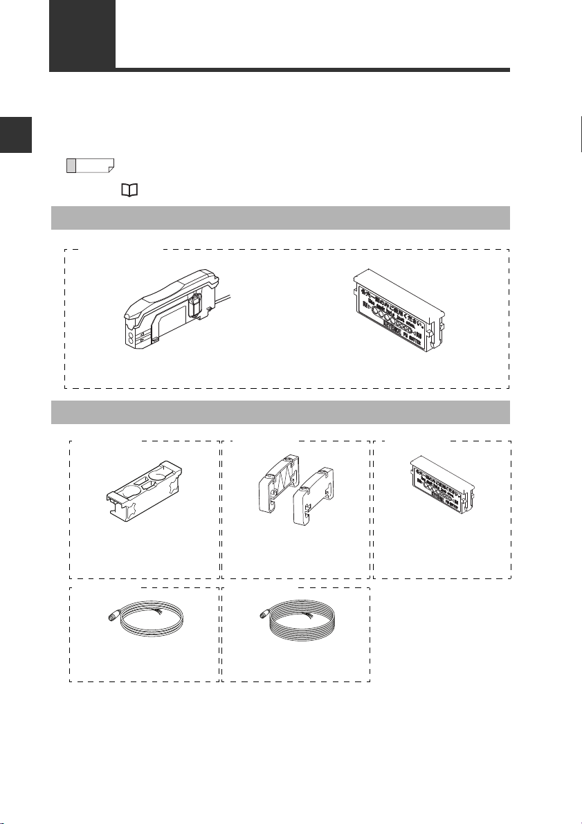
Sensor Amplifier
FS-N10 Series
Sensor amplifier x 1
Instruction Manual x 1
List of Optional Parts
OP-73880
Amplifier mounting bracket
(for main unit) x 1
For information on how to use, refer to
«Installing Sensor Amplifiers» (page 2-2).
OP-73864
M8 connector cable (2 m) x 1
Input/Output cables needed for using the
M8 connector type.
OP-26751
End unit x 2
For information on how to use, refer to
«Installing Sensor Amplifiers» (page 2-2)
OP-73865
M8 connector cable (10m) x 1
Input/Output cables needed for using the
M8 connector type.
Fiber cutter (OP-87098) x 1
OP-87098
Fiber cutter x 1
For information on how to use,
refer to «Connecting the Fiber
.
Unit» (page 2-6).
1-2
— Digital Fiber Sensor FS-N10 Series User’s Manual —
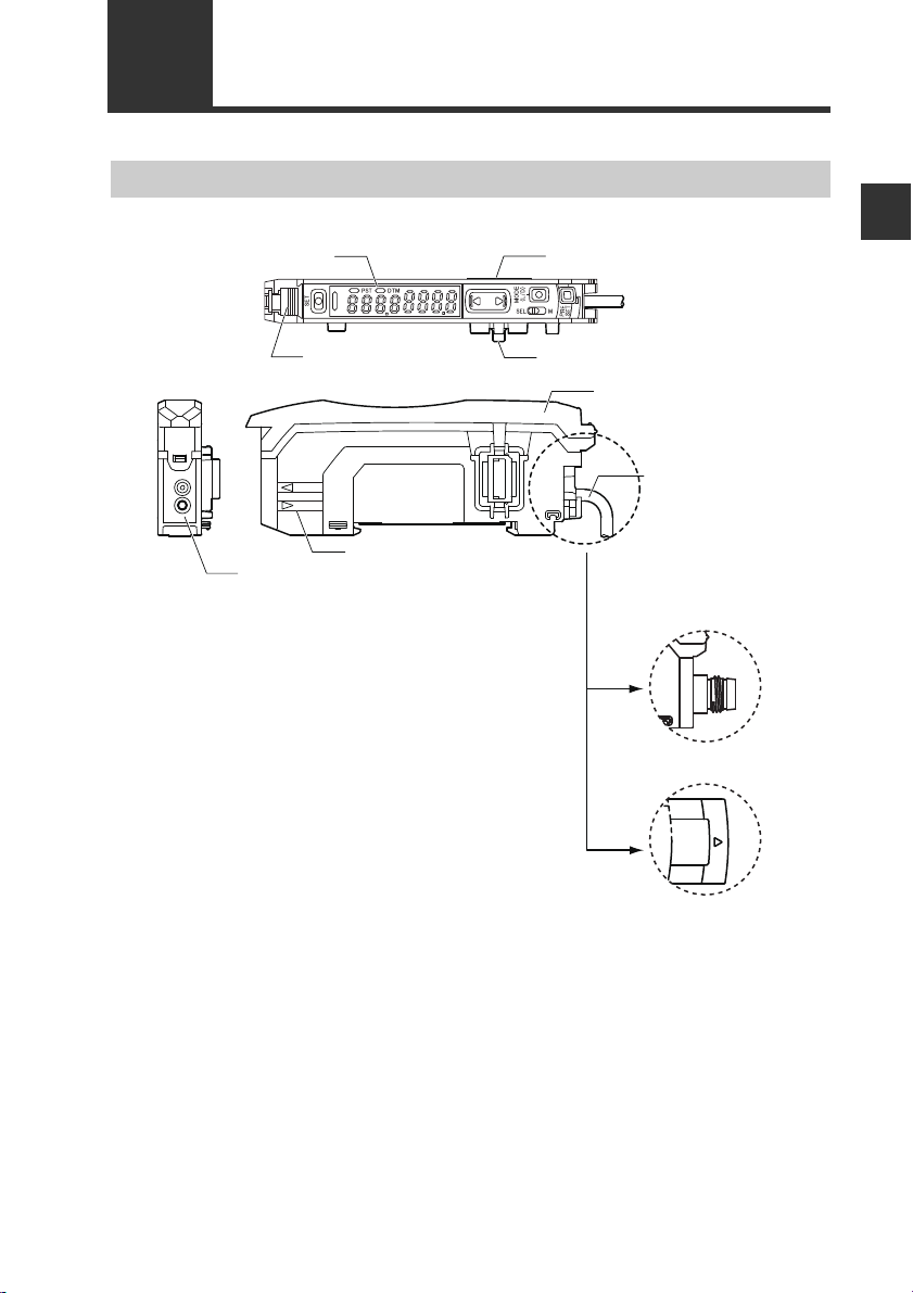
1-2
T
R
Connection
Cable
*3
Expansion connector
*1
Display/control unit
Expansion connector
*1*2
Fiber lock lever
Dust cover
Fiber transmit / receive indicators
Fiber connection ports
(FS-N1غ/N1غP)
M8 connector type
(FS-N1
غ
CN/N1غCP)
e-CON connector
(FS-N1
غ
EN)
Part Names
Sensor Amplifier
1
Before Using
*1 Expansion protective cover is installed at the factory prior to shipment.
*2 Not provided on the main unit (FS-N11 □ /N13 □ ).
*3 No connecting cables are provided for the Zero Line type (FS-N10).
— Digital Fiber Sensor FS-N10 Series User’s Manual —
1-3

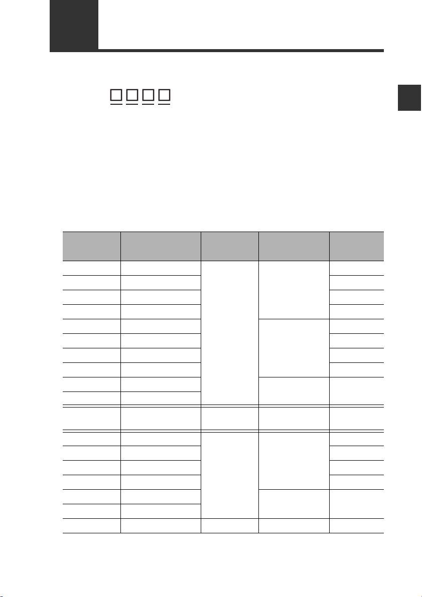
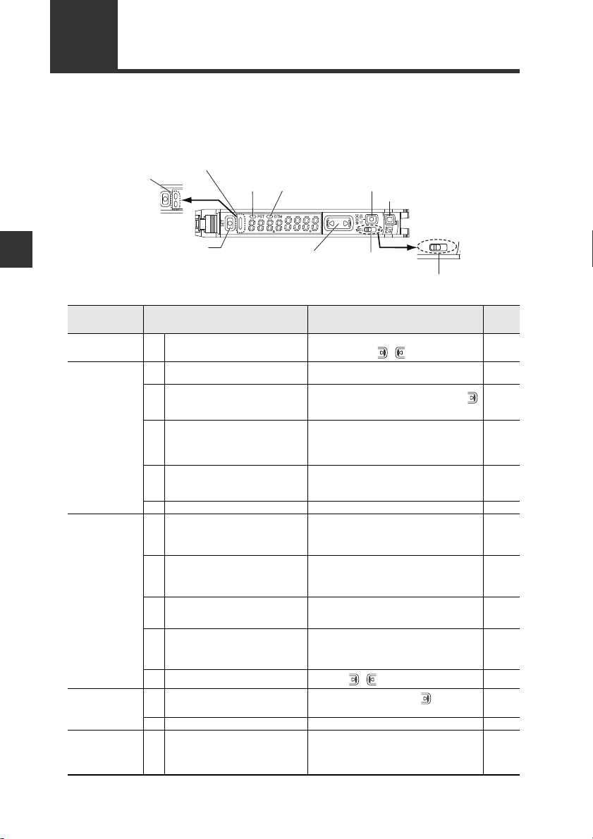
1-2 Part Names
Display/control unit
1
1-output type (FS-N11/N12/N11C/N12C/N11EN/N12EN/N11MN/N10)
Before Using
① -1
① -2
②
③
④
⑤
⑥ -1
⑥ -2
⑦
⑧
⑨
⑩
①-2
①-1
②
Item Description
Operation indicator
(1-output/Zero line type)
Operation indicator
(2-output type)
[SET] button
Set value display
(green display)
Current value display
(red display)
Manual button Used to adjust the setting value or select an option.
elect switch
Power s
(1-output type)
Channel toggle switch
(2-output type)
[PRESET] button
[MODE] button
DTM indicator
PST indicator
*
*
⑩
Indicates the current output (detection) status.
Indicates the current output (detection) status of channels 1 and 2
separately.
Use when setting sensitivity, etc.
«Adjusting Sensitivity» (page 3-5)
Displays a sett ing value or advanced setting item in this area of 7segment green indicators.
Displays the current value (received light intensity) and selection
items for detailed settings with red 7-seg ment display.
Changing power modes.
SEL: Allows you to set a power mode using the «Changing Power
M: Fixes the power mode to the «MEGA mode».
«Locking in MEGA Mode» (page 3-22)
Toggles between channels 1 and 2 for configuring the received light
intensity display or sensitivity setting.
Used for presetting or setting values or parameters.
«Preset Function» (page 3-6)
Used for toggling L-on/D-on, proceeding to advanced settings, or
confirming selections.
Lights when a DATUM mode is in effect.
«DATUM1 mode» (page 4-9)
«DATUM2 mode» (page 4-11)
Lights when preset value is set.
«Preset Function» (page 3-6)
⑨
③
④
Modes» function of basic setup.
⑧
⑦
⑥-1
⑤
⑥-2
*Not provided on the Zero Line type (FS-N10).
1-4
— Digital Fiber Sensor FS-N10 Series User’s Manual —
1-3
The numbers and letters used in product names are explained below:
Model Number Description
1
(1) Amplifier type
0: Expansion unit (Zero line)
1: Main unit (1-output)
2: Expansion unit (1-output)
3: Main unit (2-output)
4: Expansion unit (2-output)
(3) Cable type
(None): 2-meter cable
C : M8 connector
E: e—CON connector
Model (1) Amplifier type
FS-N11N
FS-N11P
FS-N12N
FS-N12P
FS-N11CN
FS-N11CP
FS-N12CN
FS-N12CP
FS-N11EN
FS-N12EN
FS-N11MN
FS-N13N
FS-N13P
FS-N14N
FS-N14P
FS-N13CP
FS-N14CP
FS-N10
Main unit (1-output)
Main unit (1-output)
Expansion unit (1-output)
Expansion unit (1-output)
Main unit (1-output)
Main unit (1-output)
Expansion unit (1-output)
Expansion unit (1-output)
Main unit (1-output)
Expansion unit (1-output)
Main unit (1-output)
Main unit (2-output)
Main unit (2-output)
Expansion unit (2-output)
Expansion unit (2-output)
Main unit (2-output)
Expansion unit (2-output)
Expansion unit ( Zero line)
(2) Special type
(None): Standard
M : Monitor output
(4) Output type
N: NPN
P: PNP
(2) Special type
Standard
Monitor
output
Standard
−− −
(3) Cable type
2-meter cable
M8 connector
e-CON
connector
2-meter cable
2-meter cable
M8 connector PNP output
(4) Output
type
NPN output
PNP output
NPN output
PNP output
NPN output
PNP output
NPN output
PNP output
NPN output
NPN output
NPN output
PNP output
NPN output
PNP output
Before Using
— Digital Fiber Sensor FS-N10 Series User’s Manual —
1-5
1
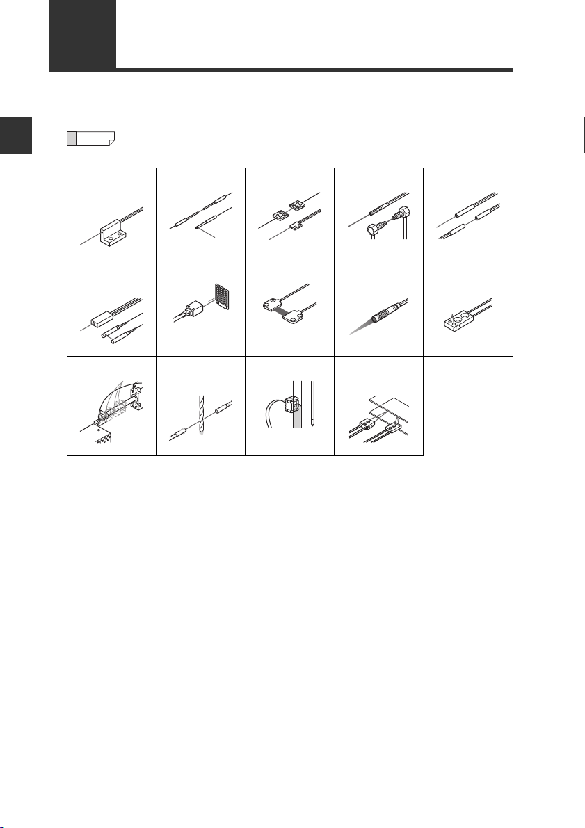
1-4
The FS-N10 Series are amplifier units. They must be used in combination with
separately-sold fiber units.
Before Using
Integrated
bracket
Fiber Units
For fiber unit details, refer to the KEYENCE gener al catalog or contact y our
nearest KEYENCE office.
Sleeve Bracket Threaded Cylinder
Narrow beam/
high power
High-flex Oil/Chemical
Retro-reflectiveArea Small spot
resistant
reflective
Liquid level LCD,
semiconductor
Definite
reflective
1-6
— Digital Fiber Sensor FS-N10 Series User’s Manual —

Installation and Connection
This chapter provides procedures for installing sensor amplifiers and
cables, as well as operating precautions.
2-1 Installing Sensor Amplifiers…………………………..2-2
2-2
Connecting the Fiber Unit
…………………………………..2-6
2
— Digital Fiber Sensor FS-N10 Series User’s Manual —
2-1
2
Installation and Connection
2-1
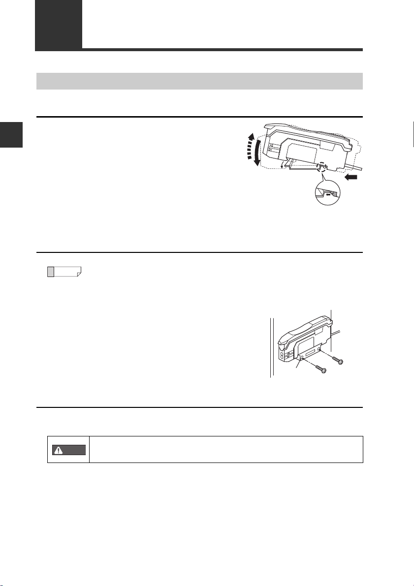
Installing Sensor Amplifiers
Mounting the Sensor Amplifier
Mounting on a DIN rail
Align the claw at the bottom of the main
1
body with the DIN rail, as shown on the
right.
While pushing the main body in the direction of the arrow (1), push down in the
direction of arrow (2).
T o release the ampl ifier, raise the amplifier
2
body in the direction of arrow (3) while
pushing in the direction of arrow (1).
Installation on a wall
This method applies only when using the main unit independently. If the
main unit is connected with an e xpan sion unit(s), use the method of mounting on a DIN rail.
Mount the amplifier on the amplifier mount-
1
ing bracket (OP-73880, sold separately),
using the same manner as «Mounting on a
DIN rail».
Secure the unit with two M3 screws as
2
shown in the illustration.
Connecting multiple amplifiers
Up to 16 expansion units can be connected to 1 main unit. Note, however, that the
2-output type is considered as 2 expansion units.
Mount on DIN rail and install on metal surface when connecting
multiple amplifiers or mounting main units together.
2-2
— Digital Fiber Sensor FS-N10 Series User’s Manual —
OP-73880
• Contact your nearest KEYENCE office when connecting a unit
other than the N-bus (KEYENCE’s wire-saving system) compatible
sensor amplifier, including FS-N10 Series, or the NU Serie s communication module.
• Turn the power off before connecting multiple expansion units.
• Do not touch the expansion conn ector with your bare hands.
• When using the FS-N10 Series as a main unit, use the products
within the expansion unit’s power voltage range if the power voltage range of the expansion unit is narrower than the FS-N10
Series.
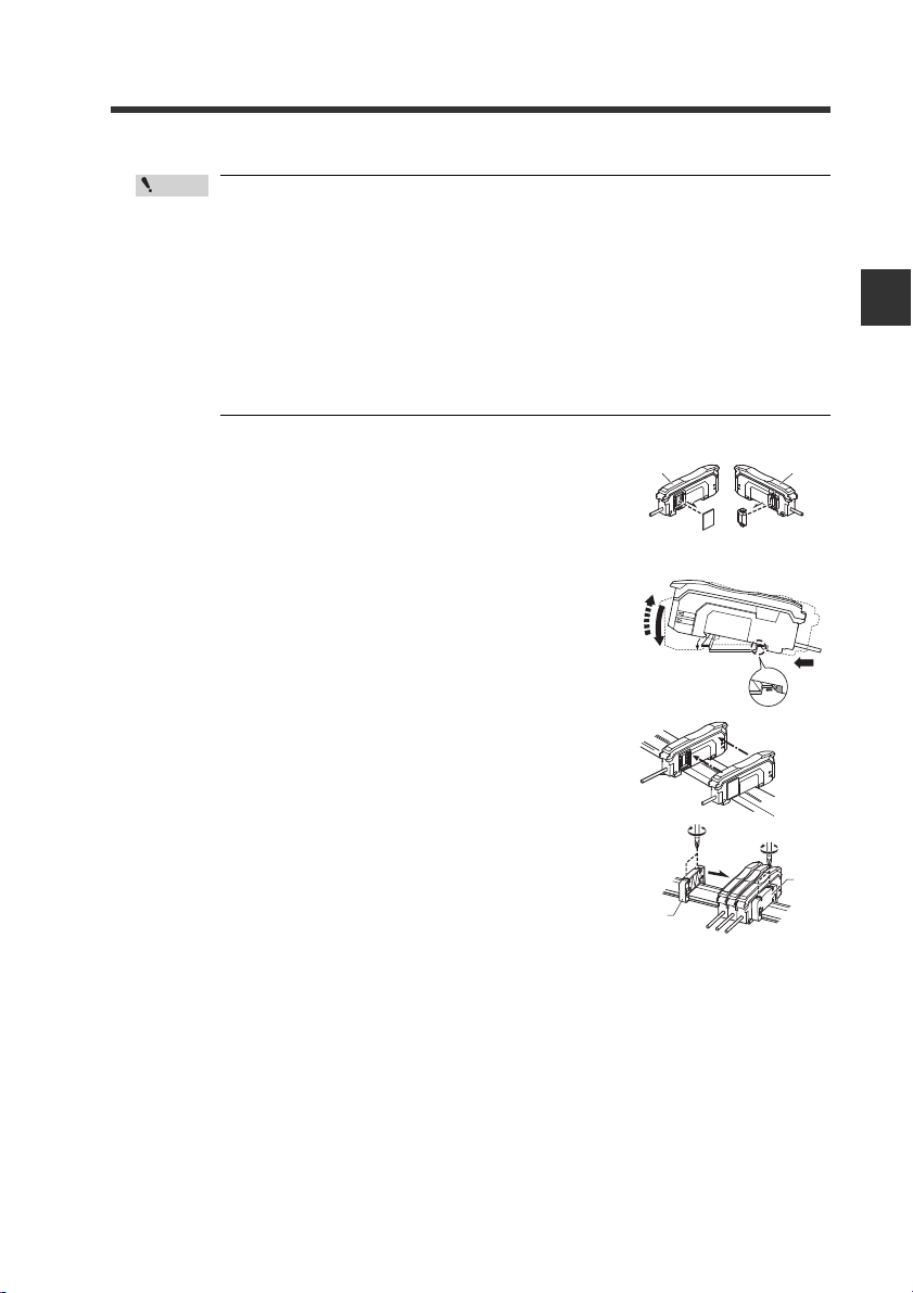
Remove the protection covers from the main unit
1
and expansion unit(s).
Mount the main unit and expansion unit(s) on the
2
DIN rail.
2-1 Installing Sensor Amplifiers
2
Installation and Connection
3
4
5
Slide the main unit and expansion unit(s)
together. Engage the 2 cla ws of the expansion unit
with the recesses on the main unit side until you
hear/ feel a click.
Attach the separately sold end units (OP-26751: a
set of 2 units) to the DIN rail in the same manner
as step (2) (Tightening torque: 0.6N•m or less).
Secure the amplifiers between the end units.
Tighten the screws at the top (2 screws × 2 units)
with a Phillips screwdriver to fix the end units.
— Digital Fiber Sensor FS-N10 Series User’s Manual —
End unit
End unit
2-3
2
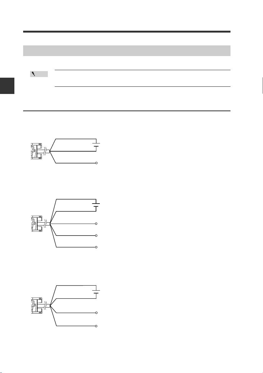
Brown
*
Output
Blue
*
Black
12 to 24 VDC
* FS-N11N/N11P only
Brown
*
Blue
*
Black
12 to 24 VDC
* FS-N13N/N13P only
Output1
External input
Output2
White
Pink
Brown
Blue
12 to 24 VDC
* Connect to a device having an input
impedance 10 kΩ or more.
Black
Output
Monitor output
(
1 to 5V
)
Orange
*
2-1 Installing Sensor Amplifiers
Wiring Diagrams for Sensor Amplifiers
· Be sure to turn off the power before wiring.
· Insulate each input or output cable that will not be used.
Installation and Connection
Wiring Diagrams for Cable Types
1-output type (FS-N11/N12)
2-output type (FS-N13/N14)
Monitor output type (FS-N11MN)
2-4
— Digital Fiber Sensor FS-N10 Series User’s Manual —
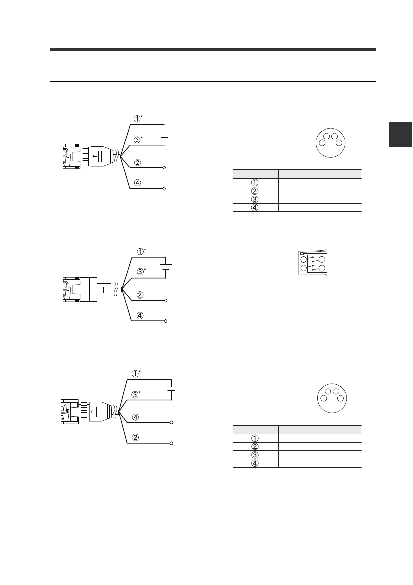
Wiring Diagrams for M8/e-CON Connector Types
12 to 24 VDC
* FS-N11CN/N11CP only
External input
Output
1
2
3
4
M8 connector Pin layout
12 to 24 VDC
* FS-N11EN only
External input
Output
e-CON connector Pin layout
1
2
3
4
12 to 24 VDC
*FS-N13CP only
Output1
Output2
1
2
3
4
M8 connector Pin layout
M8 connector, 1-output type (FS-N11C/N12C)
Pins and wire colors of OP-73864/OP-73865
2-1 Installing Sensor Amplifiers
2
Installation and Connection
Connected pin No.
e-CON connector, 1-output type (FS-N1 1EN/N12EN)
M8 connector, 2-output type (FS-N13CP/N 14 CP )
Pins and wire colors of OP-73864/OP-73865
Connected pin No.
Wire color
Brown
White
Blue
Black
Wire color
Brown
White
Blue
Black
Function
12 to 24 VDC
External input
0V
Output
Function
12 to 24 VDC
Output2
0V
Output1
— Digital Fiber Sensor FS-N10 Series User’s Manual —
2-5
2
Fiber
(2)
(1)
Always insert fiber from the side with writing
.
Fiber cutter
(OP-87098)
2-2
This section provides procedures for connecting the fiber unit and operating
precautions.
1
Connecting the Fiber Unit
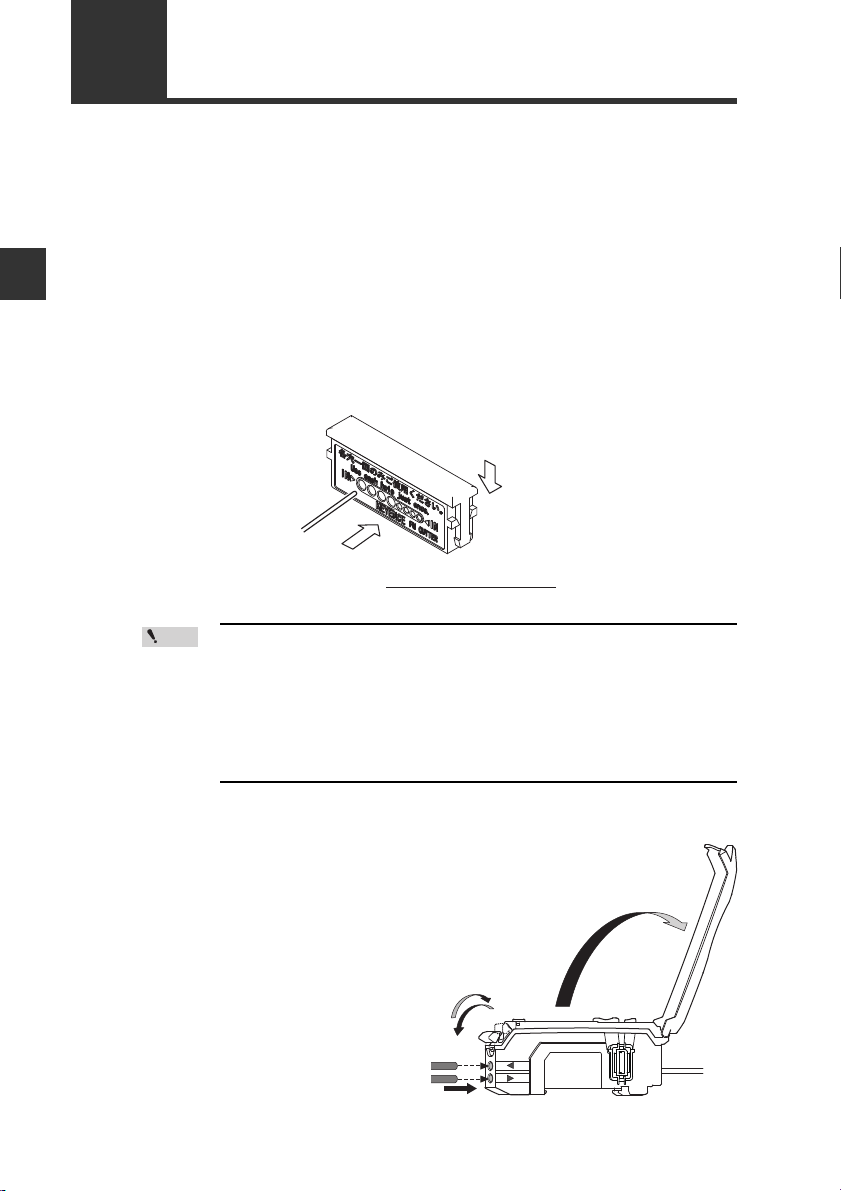
Install the fiber unit.
After the installation, check that the transmitter and receiver of the sensor are
spaced properly. Also check that the optical axis is aligned.
Installation and Connection
If the fiber unit is a free cut type, cut any excess length of the fiber.
2
(1) Insert the fiber into the hole in the cutter.
(2) Bring down the blade in a single, swift motion to cut the fiber.
Failure to observe the cautions belo w may resul t in an impr operly
cut surface, which may reduce the detection distance.
· When cutting the fiber unit, be sure to use a gray fiber cutter
(OP-87098)
· Cut the fiber unit in a single motion without stop ping the b lade
halfway through.
· Do not use the same hole twice.
Open the dust cover in the
3
direction of arrow (1).
Move the fiber lock lever down in
4
the direction of arrow (2).
2-6
— Digital Fiber Sensor FS-N10 Series User’s Manual —
(1)
(3)
(2)
2-2 Connecting the Fiber Unit
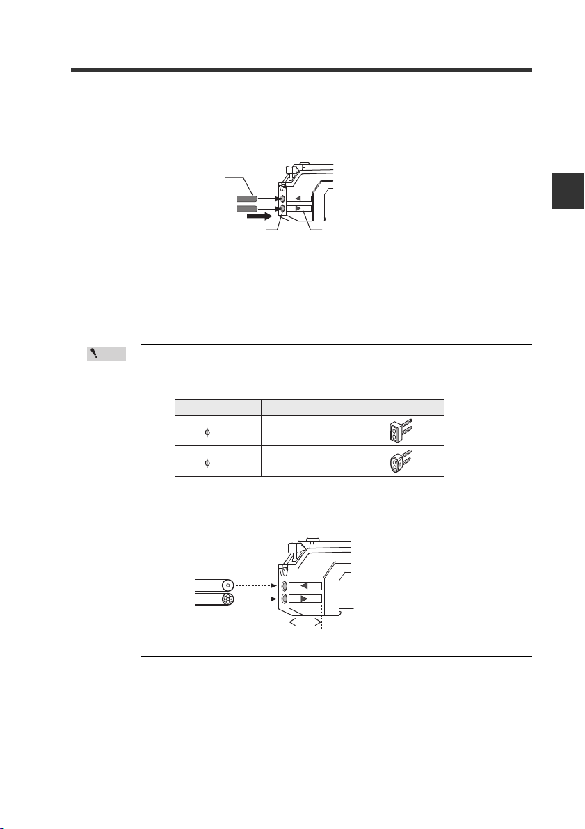
Cable outer dia
1.3
1.0
Adapter
AdapterA
(OP-26500)
AdapterB
(OP-26501)
Appearance
Receiver
Position of fiber transmit / receive indicators
Transmitter
Single-core fiber
Multi-core fiber
T
R
Insert the fiber unit into the fiber connection ports on the amplifier.
5
Insert the fiber unit until it reaches the position of the transmit / receive
indicators (approximately 14 mm).
Fiber
2
Fiber connection ports
Move the fiber lock lever ba ck in the direction of arrow (3) to secure the
6
fiber.
· If a thin fiber unit is used, an adapter provided wi th the thin fiber unit
will be required.
Make sure to use the adapter that matches the thin fiber unit.
· To connect a coaxial refl ective fiber unit to the ampl ifier, connect the
single-core fiber to the transmitter (T) side, and connect the
multiple-core fiber to the receiver side (R).
Fiber transmit / receive indicators
Installation and Connection
— Digital Fiber Sensor FS-N10 Series User’s Manual —
2-7

2
2-2 Connecting the Fiber Unit
MEMO
Installation and Connection
2-8
— Digital Fiber Sensor FS-N10 Series User’s Manual —

Basic Operation
This chapter explains basic instructions for operating and setting the
sensor amplifier.
3-1 Quick Reference………………………………………….3-2
3-2 Switching Output…………………………………………3-4
3-3 Adjusting Sensitivity……………………………………. 3-5
3-4 Setting the Current Received Light Intensity
to 0 (Zero Shift) …………………………….. … … …….3-16
3-5 Light emission/Received light intensity
adjustment (Saturation Canceling)………………. 3-18
3-6 Loading the Recommended Settings
(Recipe Function)……………………………………… 3-19
3-7 Initialization……………………………………………….3-21
3-8 Locking in MEGA Mode………………………………3-22
3-9 Disabling the Key Operation…… … .. … ……………3-23
3
— Digital Fiber Sensor FS-N10 Series User’s Manual —
3-1
3-1
Manual button
[MODE]
button
Power select switch
(1-output type))
[PRESET]
button
[SET] button
Operation indicator
(1-output/Zero line type)
DTM
indicator
PST
indicator
Operation
indicator
(2-output type)
Channel select
switch (2-output type)
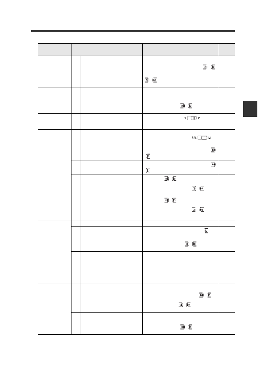
Quick Reference
The main setting operations are explained according to purpose. Refer to Chapter 4
for information on advanced function settings and explanations not given below.
3
Basic Operation
Purpose Description Operation procedures
Swiching the
output
Adjusting the
sensitivity and
integrating the
display to «100.0″
and «.0″
Adjusting the
sensitivity
Shifting the
received light
intensity to «0″
Need to prevent
the received light
intensity from
becoming satu—
rated.
3-2
1Swiching the output. (L-on/D-on)
Set the current received light intensity
2
to «100.0«. (Preset)
When preset is valid, register the
received light intensity «.0«.
3
(Work-preset)
Set the received light intensity slightly
higher than when the setting was
4
made, to «100.0«. (Maximum sensitivity
preset)
Automatically register «100.0» and «.0»
when workpiece passes by. (Full Auto
5
preset)
6 Cancel the various preset functions. Press and hold the [PRESET] button. 3-6
Set the setting value at the midpoint
between the received light intensity
7
values when a workpiece is present
and absent. (2-point calibration)
Set the setting value slightly higher
than the received light intensity value
8
at which the setting was made. (Maximum sensitivity calibration)
Set the setting value automatically
9
when a workpiece is passing thro ugh.
(Full auto calibration)
Set the setting value to the base point
10
where the workpiece is positioned.
(Positioning calibration)
11 Finely adjust the setting value directly.
Set the current display to «0«. (Zero
12
shift)
13 Cancel the zero shift function. Press and hold the [PRESET] button. 3-16
Automatically adjusts to appropriate
14
light emission and light receiving sen-
sitivity.
— Digital Fiber Sensor FS-N10 Series User’s Manual —
*
*
*
1. Press the [MODE] button.
2. Switch with the ( ) button.
Press the [PRESET] button while the PST
indicator is OFF.
After step 7, press the [PR ESET] button +
button in the state to be set as «.0″.
While the PST indicator is OFF, press and hold
the [PRESET] button. Reflective model: When
no workpiece is present. Thrubeam/Retroreflective model: When a workpiece is present.
Press and hold the [PRESET] button while the
PST indicator is OFF.
1. Press the [SET] button once when a work-
piece is present.
2. Press the [SET] button once when no work-
piece is present.
Reflective model: Press and hold the [SET] button when no workpiece is present. Thrubeam/
Retro-reflective mo
[SET] butt
on when a workpiece is present.
Press and hold the [SET] button while the
workpiece passes through.
1. Press the [SET] button once when no workpiece is present.
2. Press and hold the [SET] button at the positioning point.
Press the ( ) button.
Press the [PRESET] button + button when
t
he PST indicator
Briefly press [MODE] + [SET] buttons with the
amount of received light in maximum-saturated
condition.
12
del: Press and hold the
is OFF.
Reference
page
3-4
3-6
3-7
3-8
3-9
3-11
3-12
3-13
3-14
1-4
3-16
3-18
Purpose Description Operation procedures
1. Press and hold the [SET] button and [PRESET] button.
Loading the
recommended set-
tings
Initializing the set-
tings
Displaying the out-
put 2 display
screen with the
2-output type
Switching to the
maximum received
light intensity
power mode
Preventing
incorrect
operations
Others
(Advanced
function settings,
etc.)
Saving and
loading the
settings
Load the recommended settings.
15
(Recipe function)
Initializing (Restore to factory default
16
settings)
17 Switch to the output 2 display screen.
Adjust the power mode to the MEGA
18
mode.
19 Activat
20 Deactivating the key lock
21
22
23 Setting the advanc
24
25
26
27 Saving the settings (custom save)
28 Loading the settings (user reset)
ing the key lock
Activating the password-protected k ey
lock
Deactivating the password-protected
key lock
ed functions Press an
Setting to rescale at each preset execution so that analog output is «5 V»
output in respect to «100.0«.
Switching the display to extended display or received light intensity hold
display, etc. (sub-display)
Resetting the following values
* Received light intensity hold value
* Excess gain hold value
* Output when output 2 is in limit setting detection mode
*
2. Display the LoAd screen with the ( )
button, and press the [MODE] button.
3. Select the recipe such as r-1 FALL with the
() button.
4. Press the [MODE] button to execute.
1. Press and hold the [SET] button and [PRE-
SET] button.
2. Press the [MODE] button while on the rSt
screen.
3. Select init with the ( ) button.
4. Press the [MODE] button to execute.
Set the channel switch to .
* The output 2 sensitivity and advanced settings can be modified in this state.
Set the power select s witch to .
Pr
ess and hold the [MODE] button and the
() button simultaneously.
Press and hold the [MODE] button and the
() button simultaneously.
1. Press the ( ) button10 times while
holding down the [MODE] button.
2. Input the password with the ( ) button.
3. Press the [MODE] button to execute.
1. Press the ( ) button 10 times while
holding down the [MODE] button.
2. Input the password with the ( ) button.
3. Press the [MODE] button to deactivate the
key lock.
d hold the [MODE] button. 4-1
1. Press and hold the [MODE] button, but-
ton and [SET] button simultaneously.
2. Press the [MODE] button once or twice.
3. Select «Pr-A PrST» with ( ) button, and
press the [MODE] button.
After setting the sub-display with the advanced
function settings, press the [MODE] button
twice.
Press and hold the [MODE] button and [SET]
button.
1. Press and hold
SET] button.
2. Display the SAvE screen with the ( )
button, and press the [MODE] button.
3. Select yES with the ( ) button.
4. Press the [MODE] button to execute.
1. Press and hold the [SET] button and [PRE-
SET] button.
2. Press the [MODE] button on the rSt screen.
3. Select USEr with the ( ) button.
4. Press the [MODE] button to execute.
the [SET] button and [PRE-
3-1 Quick Reference
Reference
page
3-19
3-21
4-35
3-22
3-23
3-23
3-24
3-24
4-22
4-23
4-25
4-36
4-39
4-40
3
Basic Operation
* Not available for the FS-N10 Series shipped before March 10, 2011.
— Digital Fiber Sensor FS-N10 Series User’s Manual —
3-3

3-2
Switching Output
Output Switch (L-on/D-on)
This function configures when the output turns ON.
When the current received light inten-
1
sity is displayed, press the [MODE] button.
3
Basic Operation
The current output condition (L-on or Don) is displayed.
Press the button to switch the out-
2
put condition, and then press the
[MODE] button.
Select «D-on» if you want to output the ON
signal when the beam is blocked (a workpiece is present.) for a thrubeam or retro-reflective model.
Select «L-on» if you want to output the ON signal when the beam is received (a
workpiece is present.) for the reflective model.
The output condition is switched, and the current received light intensity is dis-
*2
played.
*1 If you do nothing for 3 seconds or more or press the [MODE] button, the received
light intensity display is automatically restored.
*2 When using the sub-display, the screen will switch between the current received
light intensity L-on/D-on screen sub-display current received light intensity
and so forth each time the [MODE] button is pressed.
«Sub Display» (page 4-23)
• Area detect mode, rising edge detect mode, and falling edge detect
mode are selectable by n.o./n.c.
«Area detection mode» (page 4-14)
«Edge detection mode» (page 4-16)
• When using a 2-output type, output can be individually selected
with channel 1/2.
*1
3-4
— Digital Fiber Sensor FS-N10 Series User’s Manual —

3-3
Adjusting Sensitivity
This manual refers to the values that select ON/OFF output of the sensor amplifiers as
«Set values.» In addition, the manual refers to the adjustment of set values as «Adjusting
Sensitivity.» This section describes the sensitivity adjusting method.
List of Sensitivity Adjusting Methods
Sensitivity adjusting method for the FS-N10 Series is broadly divided into two categories:
① Preset
Simple operation allows sensitivity adjustment concurrently with correction of the
received light intensity to «100.0» or «0.0»
This function helps preventive maintenance by eliminating dispersion of the received
light intensity due to the contents of detection or individual workpieces.
However, this is not suitable for detection of transparent workpiece because there is a
small difference in the received light intensity between presence and absenc e of a
workpiece.
② Calibration
Sensitivity can be adjusted by a simple operation. This function does not correct t he
received light intensity.
This function is applied for using the received light intensity without correction or for
high-precision detection.
Calibration is also available in a preset state.
How to select sensitivity adjusting method
3
Basic Operation
Sensitivity
adjusting
method
Preset
Calibration
Basics
At times
like this
Basic
At times
like this
Status of use Functions Contents Reference
Using thrubeam/retro-reflective
models
Using reflective model
Not successfully displaying the
intensity level as «100.0» and
«.0» depending on the presence
of a workpiece.
Mobile object moves fast
ing thrubeam/retro-reflective
Us
models
Mobile body moves fast
Using the unit in the environ-
ment that tends to get dirty
easily.
Using the unit for positioning
Using the unit for
sion detection
high-preci-
Preset
Preset to maximum sensitivity
Work preset
Full automatic
preset
Two-point
calibration
Full automatic
calibration
Maximum sensitivity calibration
Positioning calibration
Percentage calibration
When there is no workpiece, by simply pressing the PRESET button,
sensitivity adjustment is completed.
When there is no workpiece, by simply holding the PRESET button,
sensitivity adjustment is completed.
The status in which «100.0» or «.0» is
displayed can be set at your choice
Preset is enabled by using a f ast-
rkpiece.
moving wo
The setting can be established just
by pressing the [SET] button once
when a workpiece is present and
absent.
Calibration is enabled by using a
fast-moving workpiece.
The setting seldom causes malfunc-
tion even in the environment that
tends to get dirty easily.
The setting suitable f
available.
Effective for making correction from
external devices such as PLC.
or positioning is
— Digital Fiber Sensor FS-N10 Series User’s Manual —
3-6
3-8
3-7
3-9
3-11
3-13
3-12
3-14
3-15
3-5

3
Green PST lights up
Setting value
is
«50.0″
Current value is
«
100.0″
3-3 Adjusting Sensitivity
Preset Function
Enabling the preset function
When the PST indicator is not lit, press the [PRESET] button.
The PST indicator lights
in green. The current
value is set to «100.0″
and the setting value is
set to «50.0″.
Basic Operation
Disabling the preset function
When the PST indicator is lit, press and hold the [PRESET] button.
• The PST indicator turns off, indicating that the preset function has been disabled.
• Once the preset function is disabled, the setting value is recalculated while
retaining the ratio of the setting value and received light intensity.
3-6
— Digital Fiber Sensor FS-N10 Series User’s Manual —
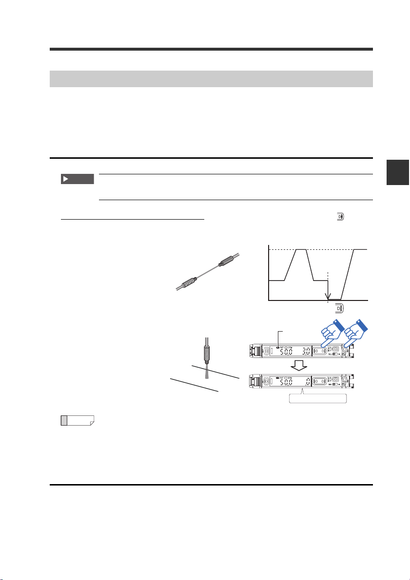
3-3 Adjusting Sensitivity
Work-Preset Function
This function calibrates the current value to «.0«. After the preset function has been
executed with «100.0» displayed, and then executing this function wit h «.0» displayed, 2
random set points can be calibrated to «100.0» and «.0″.
* Not available for the FS-N10 Series shipped before March 10, 2011.
Enabling the work-preset function
The work-preset function can be used with the preset function (when
preset is enabled).
While the preset function is enabled, press the [PRESET] button and button
simultaneously.
The received light intensity
at that point is set to «.0″.
The value set to «100.0» using
the preset function does not
change.
Green «PST»
lights up
Current value is «.0»
Reference
Even if the received light intensity is low during preset and is high during
work-preset, the value is set to «100.0» during preset and «.0» during work-
preset. When the actual received light intensity increases, the display will
approach «.0«. (The preset saturation level is decreased with respect to
«100.0«.)
3
Basic Operation
Disabling the work-preset function
When the PST indicator is lit, press and hold the [PRESET] button.
• The PST indicator turns off, indicating that the work-preset function has been
disabled.
— Digital Fiber Sensor FS-N10 Series User’s Manual —
3-7
3-3 Adjusting Sensitivity
Setting value
Setting value
Thrubeam Model/Retro-reflective Model
Reflective Model
Received light intensity Received light intensity
No workpiece
With workpiece
No workpiece*
With workpiece*
1
1
Saturation point
«100.0«
«50.0«
«.0«
«100.0»
«50.0»
«.0«
Saturation point
* Where detection occurs on a target having a background, the maximum sensitiv-
ity setting ignores the background. Maximum sensitivity setting is not available if
the background is more reflective than the workpiece.
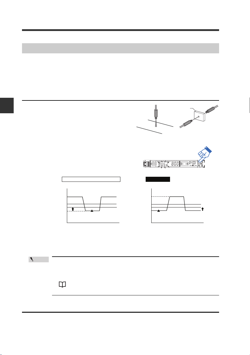
Maximum Sensitivity Preset Function
This function calibrates the reference state to «.0» and the state at which the received
light intensity is slightly higher as «100.0″.
This function is useful with the reflective model to detect while using the background
as a reference.
* Not available for the FS-N10 Series shipped before March 10, 2011.
Enabling the maximum sensitivity preset function
3
Basic Operation
When no workpiece is present for the
1
reflective model, or when a workpiece
is present for thrubeam model/retroreflective model, press and hold the
[PRESET] button for 3 seconds or more
while the PST indicator is OFF.
Release the button when «
Calibration is complete after the setting
value flashes momentarily, and then stops
(lights up).
The PST indicator lights in green, and the
setting value is set to «
50.0
«.
• When th e amount of the light received is in saturated state (at a
value higher than at the time of extended display on page 4-30),
maximum sensitivity preset function cannot be implemented.
(«—- —-» is indicated when operating 1.)
«Light emission/Received light intensity adjustment (Saturation
Canceling)» (page 3-18)
Auto
» flashes.
Disabling the maximum sensitivity preset function
When the PST indicator is lit, press and hold the [PRESET] button.
• The PST indicator turns off, indicating that the maxi mum sensitivity preset func-
tion has been disabled.
3-8
— Digital Fiber Sensor FS-N10 Series User’s Manual —
Loading…
ВНИМАНИЕ!
Автоматический перевод описания осуществляется только в текстовой форме. Информация, представленная поставщиком в виде картинок или надписей на фотографии, к сожалению не может быть переведена по техническим причинам. Показать оригинал описания данного товара.
Характеристики товара: |
|
| Бренд: | Bojke/Boyi Jingke; |
| Материал: | Смесь; |
| Место происхождения: | Китайский материк; |
| Категория выходной модели: | Фотоэлектрические датчики; |
| Принцип работы: | Волокно -резиновый датчик; |
| Применимая сцена: | Фабрика; |
| Категория датчика: | Волоконно -оптический датчик; |
| Оптоволокно: | Не заслуживает оптического волокна; PRS3Y10 отражение M3 один метр линия; PRS4Y10 отражение M4 One -Meter Line; PR6Y10 отражение M6 Line One Meter Line; Pt3y10 Пары съемки M3 один метр; Pt4y10 Pair M4 One -Meter Line; PT6Y10 PARE M6 ONE METER LINE; Рефлекторная двухметральная линия M3 M4 M6; Платите двухметерной линии M3 M4 M6; |
| Выбор: | Рекомендую ER2-22NH NPN; ER2-22H NPN; ER2-22HP PNP; |
+7 (495) 215-16-67
8 (800) 333-16-67
с 9:00-19:00 — ежедневно (МСК)
Заказать звонок
×
Обратный звонок
Представьтесь
Номер вашего телефона
Ваш вопрос
я даю согласие Shopozz на обработку персональных данных
в соответствии с Федеральным законом от 27.07.2006 года №152-ФЗ «О персональных данных», на условиях и для целей, определенных Политикой конфиденциальности.
×
Доставка товаров с аукциона eBay и интернет-магазинов США в
Россию (Москва, Санкт-Петербург, Новосибирск, Екатеринбург,
Казань, Нижний Новгород, Челябинск, Красноярск, Самара, Уфа,
Ростов-на-Дону, Омск, Краснодар, Воронеж, Волгоград, Пермь и
другие города).
© Shopozz — сервис покупок за рубежом