

68
ASRock FM2A55M-DGS Motherboard
1. Введение
Благодарим вас за покупку материнской платы ASRock FM2A55M-DGS надежной
материнской платы, изготовленной в соответствии с постоянно предъявляемыми ASRock
жесткими требованиями к качеству. Она обеспечивает превосходную производительность
и отличается отличной конструкцией, которые отражают приверженность ASRock качеству
и долговечности.
Данное руководство по быстрой установке включает вводную информацию о материнской
плате и пошаговые инструкции по ее установке. Более подробные сведения о плате
можно найти в руководстве пользователя на компакт-диске поддержки.
Спецификации материнской платы и программное обеспечение
BIOS иногда изменяются, поэтому содержание этого руководства
может обновляться без уведомления. В случае любых
модификаций руководства его новая версия будет размещена на
веб-сайте ASRock без специального уведомления. Кроме того,
самые свежие списки поддерживаемых модулей памяти и
процессоров можно найти на сайте ASRock.
Адрес веб-сайта ASRock
http://www.asrock.com
При необходимости технической поддержки по вопросам данной
материнской платы посетите наш веб-сайт для получения
информации об используемой модели.
www.asrock.com/support/index.asp
1.1 Комплектность
Материнская плата ASRock FM2A55M-DGS
(форм-фактор Micro ATX: 8,9 x 7,6 дюйма / 22,6 x 19,3 см)
Руководство по быстрой установке ASRock FM2A55M-DGS
Компакт-диск поддержки ASRock FM2A55M-DGS
2 x кабель данных Serial ATA (SATA) (дополнительно)
1 x I/O Щит Группы ввода / вывода
ASRock напоминает…
Для обеспечения максимальной производительности ОС Windows
®
7 / 7 64-bit / Vista
TM
/ Vista
TM
64-bit рекомендуется в BIOS выбрать для
параметра Storage Configuration (Конфигурация запоминающего
устройства) режим AHCI. Подробные сведения о настройке BIOS см.
в руководстве пользователя на прилагаемом компакт-диске.
Ру
сский
-
Страница 1
1 FM2A55M-DGS User Manual V ersion 1.0 Published August 2012 Copyright©2012 ASRock INC. All rights reserved.[…]
-
Страница 2
2 Copyright Notice: No part of this manual may be reproduced, transcribed, transmitted, or translated in any language, in any form or by any means, except duplication of documentation by the purchaser for backup purpose, without written consent of ASRock Inc. Products and corporate names appearing in this manual may or may not be regis- tered trade[…]
-
Страница 3
3 Contents 1. Introduction ………………………………………………………. 5 1.1 Package Contents ………………………………………………… ………… 5 1.2 Specications ………………………………………………………………….. 6 1.3 Unique Features ……………………………………[…]
-
Страница 4
4 3. UEFI SETUP UTILITY ………………………………………….. 37 3.1 Introduction …………………………………………………………………….. 37 3.1.1 UEFI Menu Bar ………………………………………………………. 37 3.1.2 Navigation Keys …………………………………………………….[…]
-
Страница 5
5 1. Introduction Thank you for purchasing ASRock FM2A55M-DGS motherboard, a reliable moth- erboard produced under ASRock’s consistently stringent quality control. It delivers excellent performance with robust design conforming to ASRock’s comm itment to quality and endurance. In this manual, chapter 1 and 2 contain introduction of the motherbo[…]
-
Страница 6
6 1.2 Specications Platform — Micro A TX Form Factor: 8.9-in x 7.6-in, 22.6 cm x 19.3 cm — Solid Capacitor for CPU power CPU — Support for Socket FM2 100W processors — Supports AMD’s Cool ‘n’ Quiet TM T echnology — UMI-Link GEN2 Chipset — AMD A55 FCH (Hudson-D2) Memory — Dual Channel DDR3 Memory T echnology — 2 x DDR3 DIMM slots — Support […]
-
Страница 7
7 Rear Panel I/O I/O Panel — 1 x PS/2 Mouse/Keyboard Port — 1 x D-Sub Port — 1 x DVI-D Port — 4 x Ready-to-Use USB 2.0 Ports — 1 x RJ-45 LAN Port with LED (ACT/LINK LED and SPEED LED) — HD Audio Jack: Line in / Front Speaker / Microphone Connector — 6 x SA T A2 3.0 Gb/s connectors, support RAID (RAID 0, RAID 1 and RAID 10), NCQ, AHCI and “Hot Plu[…]
-
Страница 8
8 W ARNING Please realize that there is a certain risk involved with overclocking, including adjusting the setting in the BIOS, applying Untied Overclocking T echnology , or using third-party overclocking tools. Overclocking may affect your system’ s stability , or even cause damage to the components and devices of your system. It should be done […]
-
Страница 9
9 1.3 Unique Features ASRock Extreme T uning Utility (AXTU) A SRock Extre me T uning Utility (AXTU) is an all-in-o ne tool to ne-tu ne di f fe rent syste m fun ctions in a user -friendly inter face, whic h in clude s Ha rdware Moni tor , Fa n Co ntrol, Over clocki ng, OC DNA, IES and XFast RAM. In Hardware Monitor , it shows the major readings of y[…]
-
Страница 10
10 ASRock APP Charger I f y o u d es i r e a f as t e r, l e ss r e s tr i c te d w a y o f c h a rg i n g y o u r Apple device s, suc h as iPhone /iPad/iPo d T ouch, ASRock has prepared a wonderful solution for you — ASRock APP Charger . Si mpl y in sta ll t he AP P C har ge r d riv er, i t m ake s y ou r i Pho ne charge much quickly from your com[…]
-
Страница 11
1 1 ASRock Crashless BIOS AS Ro ck Cr as hl es s B IO S a ll ow s u se rs to up da te th ei r B IO S without fear of failing. If power loss occurs during the BIOS up- date process, ASRock Crashless BIOS will automatically nish the BIOS update procedu[…]
-
Страница 12
12 ASRock Interactive UEFI A SR oc k I nt er act iv e U EF I i s a b len d of sy st em c on fig ur at io n to ol s , c oo l s ou nd ef fe ct s a nd s tu n ni ng v is ua ls . T he u np re c- edented UEFI provides a more attractive interface and bringsa lotmore[…]
-
Страница 13
13 1.4 Motherboard Layout 1 A TX 12V Power Connector (A TX12V1) 16 Chassis Fan Connector (CHA_F AN1) 2 CPU Heatsink Retention Module 17 System Panel Header (P ANEL1) 3 CPU Socket 18 Print Port Header (LPT1) 4 CPU Fan Connector (CPU_F AN1) 19 USB 2.0 Header (USB4_5) 5 2 x 240-pin DDR3 DIMM Slots 20 USB 2.0 Header (USB8_9) (Dual Channel: DDR3_A1, DDR[…]
-
Страница 14
14 1.5 I/O Panel * There are two LED next to the LAN port. Please refer to the table below for the LAN port LED indications. LAN Port LED Indications Activity/Link LED SPEED LED Status Description Status Description Off No Link Of f 10Mbps connection Blinking Data Activity Orange 100Mbps connection On Link Green 1Gbps connection 1 PS/2 Mouse Port ([…]
-
Страница 15
15 2. Installation This is a Micro A TX form factor (8.9-in x 7.6-in, 22.6 cm x 19.3 cm) motherboard. Before you install the motherboa rd, study the conguration of your chassis to ensure that the motherboard ts into it. Pre-installation Precautions T ak e no te of th e fo llo wing pr ecau tio ns be fore you ins tal l m othe rbo ard components[…]
-
Страница 16
16 2.1 CPU Installation Step 1. Unlock the socket by lifting the lever up to a 90 o angle. Step 2. Position the CPU directly above the socket such that the CPU corner with the golden triangle matches the socket corner with a small triangle. Step 3. Carefully insert the CPU into the socket until it ts in place. The CPU ts only in one correct o[…]
-
Страница 17
17 2.3 Installation of Memory Modules (DIMM) This mot herboar d pr ovides t wo 2 40-pin D DR3 (Dou ble Data R ate 3) DI MM slots , and su pport s Dual C hannel M emory T ec hnolog y . F or dua l chan nel co nfigu ratio n, yo u alw ays n eed to i nst all tw o ide nti cal (t he sa me b ran d, s peed , si ze a nd ch ip- type) memory modules in the DDR[…]
-
Страница 18
18 2.4 Expansion Slots (PCI and PCI Express Slots) There is 1 PCI slot and 2 PCI Express slots on this motherboard. PCI Slots: PCI slots are used to install expansion cards that have the 32-bit PCI interface. PCIE Slots: PCIE1 (PCIE x16 slot) is used for PCI Express x16 lane width graphics cards. PCIE2 (PCIE x1 slot) is used for PCI Express cards w[…]
-
Страница 19
19 2.5 AMD Dual Graphics Operation Guide This motherboard supports AMD Dual Graphics feature. AMD Dual Graphics brings multi-GPU performance capabilities by enabling an AMD A55 FCH (Hudson-D2) integrated graphics processor and a discrete graphics processor to operate simultaneously with combined output to a single display for blisteringly-fast fram[…]
-
Страница 20
20 * Dual Graphics appearing here is a registered trademark of AMD T echnologies Inc., and is used only for identication or explanation and to the owners’ benet, without intent to infringe. * For further information of AMD Dual Graphics technology , please check AMD website for up dates and details. Step 9. Click “Enable CrossFire TM ” […]
-
Страница 21
21 2. If you have installed onboard VGA driver from our support CD to your system already , you can freely enjoy the benets of dual monitor function after your system boots. If you haven’t installed onboard VGA driver yet, please install onboard VGA driver from our support CD to your system and restart your computer . 2.6 Dual Monitor and Surr[…]
-
Страница 22
22 Surround Display Feature This motherboard supports surround display upgrade. With the internal VGA output support (D-Sub and DVI-D) and external add-on PCI Express VGA cards, you can easily enjoy the benets of surround display feature. Please refer to the following steps to set up a surround display environment: 1. Install the PCI Express VGA[…]
-
Страница 23
23 For Windows ® 7 / 7 64-bit / Vista TM / Vista TM 64-bit OS: Right click the desktop, choose “Personalize”, and select the “Display Settings” tab so that you can adjust the parameters of the multi-monitor according to the steps below . A. Click the number ”2” icon. B. Cli ck the ite ms “ Thi s is my ma in m oni tor” an d “E xte[…]
-
Страница 24
24 USB 2.0 header (9-pin, black) CIR header (4-pin, gray) 2.7 ASRock Smart Remote Installation Guide AS Roc k S mar t Re mot e i s o nly u sed fo r AS Roc k m oth erb oar d wi th C IR he ade r . Plea se ref er to b elow pr ocedur es for th e q uick i nstall ation a nd usa ge of ASR ock Smart Remote. Step1. Find the CIR header located next to the US[…]
-
Страница 25
25 * ASRock Smart Remote is only supported by some of ASRock motherboards. Please refer to ASRock website for the motherboard support list: http://www .asrock.com 1. Only one of the front USB port can support CIR function. When the CIR function is enabled, the other port will remain USB function. 2. Multi-Angle CIR Receiver is used for front USB on[…]
-
Страница 26
26 2.8 Jumpers Setup T h e i l l u s t r a t io n s h o w s h o w j u m p e r s a r e setup. When the jumper cap is placed on pins, the jumper is “Short”. If no jumper cap is placed on pins, the jumper is “Open”. The i l lu s t r at i o n s h ow s a 3 — pi n j u m p er w h os e pin1 and pin2 are “Short” when jumper cap is placed on thes[…]
-
Страница 27
27 2.9 Onboard Headers and Connectors Onboar d headers and con nectors a re NOT jum pers. Do NOT place jumper caps over these headers and connectors. Placing jumper caps over the headers and connectors will cause permanent damage of the motherboard! Serial A T A2 Connectors These six Serial A T A2 (SA T A_1: see p.13, No. 7) (SA T A2) connectors su[…]
-
Страница 28
28 Infrared Module Header This header supports an (5-pin IR1) optional wireless transmitting (see p.13 No. 26) and receiving infrared module. Front Panel Audio Header This is an interface for the front (9-pin HD_AUDIO1) panel audio cable that allows (see p.13 No. 24) convenient connection and control of audio devices. Consumer Infrared Module Heade[…]
-
Страница 29
29 Chassis Speaker Header Please connect the chassis (4-pin SPEAKER 1) speaker to this header . (see p.13 No. 14) System Panel Header This header accommodates (9-pin P ANEL1) several system front panel (see p.13 No. 17) functions. Connect the po wer switch , reset switc h and s ystem stat us indica tor on the chassis to this header according to the[…]
-
Страница 30
30 CPU Fan Connectors Please connect the CPU fan (4-pin CPU_F AN1) cable to the connector and (see p.13 No. 4) match the black wire to the ground pin. Though this motherboard provides 4-Pin CPU fan (Quiet Fan) support, the 3-Pin CPU fan still can work successfully even without the fan speed control function. If you plan to connect the 3-Pin CPU fan[…]
-
Страница 31
31 2.10 Serial A T A2 (SA T A2) Hard Disks Installation This motherboard adopts AMD A55 FCH (Hudson-D2) chipset that supports Serial A T A2 (SA T A2) hard disks and RAID (RAID 0, RAID 1 and RAID 10) functions. Y ou may install SA T A3 hard disks on this motherboard for internal storage devices. This section will guide you to install the SA T A2 har[…]
-
Страница 32
32 Caution 1. Without SA T A 15-pin power connector interface, the SA T A2 Hot Plug cannot be processed. 2. Even some SA T A2 HDDs provide both SA T A 15-pin power connector and IDE 1×4-pin conventional power connector interfaces, the IDE 1×4-pin conventional power connector interface is denitely not able to support Hot Plug and will cause the H[…]
-
Страница 33
33 How to Hot Plug a SA T A2 HDD: Points of attention, before you process the Hot Plug: Please do follow below instruction sequence to process the Hot Plug, improper procedure will cause the SA T A2 HDD damage and data loss. Connect SA T A 15-pin power cable connector (Black) end to SA T A2 HDD. How to Hot Unplug a SA T A2 HDD: Points of attention,[…]
-
Страница 34
34 2.13 Driver Installation Guide T o install the drivers to your system, please insert the support CD to your optical drive rst. Then, the drivers compatible to your system can be auto-detected and listed on the support CD driver page. Please follow the order from up to bottom side to install those required drivers. Therefore, the drivers you i[…]
-
Страница 35
35 Using SA T A2 HDDs without NCQ and Hot Plug functions (IDE mode) STEP 1: Set up UEFI. A. Enter UEFI SETUP UTILITY Advanced screen Storage Conguration. B. Set the “SA T A Mode” option to [IDE]. STEP 2: Install Windows ® XP OS on your system. 2.15 Installing Windows ® 7 / 7 64-bit / Vista TM / Vista TM 64-bit / XP W ithout RAID Functions […]
-
Страница 36
36 STEP 1: Set up UEFI. A. Enter UEFI SETUP UTILITY Advanced screen Storage Conguration. B. Set the “SA T A Mode” option to [IDE]. STEP 2: Install Windows ® 7 / 7 64-bit / Vista TM / Vista TM 64-bit OS on your system. Using SA T A2 HDDs without NCQ and Hot Plug functions (IDE mode) 2.15.2 Installing Windows ® 7 / 7 64-bit / Vista TM / Vist[…]
-
Страница 37
37 3. UEFI SETUP UTILITY 3.1 Introduction ASRock Inter active UEF I is a blend of syst em congu ration to ols, cool sound ef- fects and stunning visuals. Not only will it make BIOS setup less difcult but also a lot more amusing. This section explains how to use the UEFI SETUP UTILITY to congure your system. The UEFI chip on the motherboard[…]
-
Страница 38
38 3.1.2 Navigation Keys Please check the following table for the function description of each navigation key . Navigation Key(s) Function Description / Moves cursor left or right to select Screens / Moves cursor up or down to select items + / — T o change option for the selected items <T ab> Switch to next function <Enter> T o bring up[…]
-
Страница 39
39 3.3 OC T weaker Screen In the OC T weaker screen, you can set up overclocking features. EZ OC Mode Y ou can use this option to adjust EZ overclocking setting. Please note that overclocing may cause damage to your components and motherboard. It should be done at your own risk and expense. CPU Conguration Overclock Mode U se th is to se le ct O[…]
-
Страница 40
40 Multiplier/V oltage Change This item is set to [Auto] by default. If it is set to [Manual], you may adjust the value of Processor Frequency and Processor V oltage. However , it is recommended to keep the default value for system stability . Boost Frequency Multiplier For safety and system stability , it is not recommended to adjust the value of […]
-
Страница 41
41 DRAM Timing Control Power Down Enable Use this item to enable or disable DDR power down mode. Bank Interleaving Interleaving allows memory accesses to be spread out over banks on the same node, or accross nodes, decreasing access contention. Channel Interleaving It allo ws you to enab le Cha nnel M emory Interl eaving. Con guration op- tions:[…]
-
Страница 42
42 RAS# Cycle Time (tRC) Use this item to change RAS# Cycle T ime (tRC) Auto/Manual setting. The default is [Auto]. Write Recovery T ime (tWR) Use this item to change Write Recovery Time (tWR) Auto/Manual setting. The default is [Auto]. Refresh Cyle Time (tRFC) Use this item to change Refresh Cyle T ime (tRFC) Auto/Manual setting. The default is [A[…]
-
Страница 43
43 3.4 Advanced Screen In this section, you may set the congurations for the following items: CPU Congu- ration, Nouth Bridge Conguration, South Bridge Conguration, Storage Congura- tion, Super IO Conguration, ACPI Conguration, USB Conguration and Network Conguration. Setting wrong values in this section may cause the sys[…]
-
Страница 44
44 3.4.1 CPU Conguration Core C6 Mode Use this item to enable or disable Core C6 mode. The default value is [Enabled]. Package C6 Mode This item appears only when you enable the item “Core C6 Mode”. Use this item to enable or disable Package C6 mode. The default value is [Dis- abled]. Cool ‘n’ Quiet Use this item to enable or disable[…]
-
Страница 45
45 3.4.2 North Bridge Conguration Primary Graphics Adapter This item will switch the PCI Bus scanning order while searching for video card. It allows you to select the type of Primary VGA in case of multiple video controllers. The default value of this feature is [PCI Express]. Con- guration options: [Onboard], [PCI] and [PCI Express]. Share […]
-
Страница 46
46 3.4.3 South Bridge Conguration Onboard HD Audio Select [Auto], [Enabled] or [Disabled] for the onboard HD Audio feature. If you select [Auto], the onboard HD Audio will be disabled when PCI Sound Card is plugged. Front Panel Select [Auto] or [Disabled] for the onboard HD Audio Front Panel. Onboard LAN This allows you to enable or disable the […]
-
Страница 47
47 3.4.4 Storage Conguration SA T A Controller Use this item to enable or disable the “SA T A Controller” feature. SA T A Mode Use th is item t o adjust SA T A Mode. The d efault va lue of th is option is [AHCI Mode]. Conguration options: [AHCI Mode], [RAID Mode] and [IDE Mode]. If you set this item to RAID mode, it is suggested to instal[…]
-
Страница 48
48 3.4.5 Super IO Conguration Serial Port Use this item to enable or disable the onboard serial port. Serial Port Address Use this item to set the address for the onboard serial port. Conguration options: [3F8h / IRQ4] and [3E8h / IRQ4]. Infrared Port Use this item to enable or disable the onboard infrared port. Infrared Port Address Use this[…]
-
Страница 49
49 3.4.6 ACPI Conguration Suspend to RAM Use this item to select whether to auto-detect or disable the Suspend-to- RAM feature. Select [Auto] will enable this feature if the OS supports it. Check Ready Bit Use this item to enable or disable the feature Check Ready Bit. Restore on AC/Power Loss This allows you to set the power state after an unex[…]
-
Страница 50
50 USB Mouse Power On Use this item to enable or disable USB Mouse to power on the system. ACPI HPET table Use this item to enable or disable ACPI HPET T able. The default value is [Enabled]. Please set this option to [Enabled] if you plan to use this moth- erboard to submit Windows ® Vista TM certication.[…]
-
Страница 51
51 3.4.7 USB Conguration USB 2.0 Controller Use this item to enable or disable the use of USB 2.0 controller . Legacy USB Support Use this option to select legacy support for USB devices. There are four con guration options: [Enabled] , [Auto], [Disabled] and [UEFI Setup Only]. The default value is [Enabled]. Please refer to below description[…]
-
Страница 52
52 3.4.8 Network Conguration Internet Setting Use this item to set up the internet connection mode. Conguration options: [DHCP (Auto IP)] and [PPPOE]. UEFI Download Server Use this item to select UEFI rmware download server for Internet Flash. Conguration options: [Asia], [Europe], [USA] and [China].[…]
-
Страница 53
53 3.5 T ool Sound Effect Enable or disable sound effects in the setup utility . System Browser System Browser can let you easily check your current system congura- tion in UEFI setup. OMG(Online Management Guard) Administrators are able to establish an internet curfew or restrict internet access at specied times via OMG. Y ou may schedule th[…]
-
Страница 54
54 Internet Flash Int erne t F lash sea rche s f or av aila ble UE FI fi rmwa re up date s fr om ou r servers. In other words, the system can auto-detect the latest UEFI from our servers and ash them without entering Windows OS. Please note that you must be running on a DHCP congured computer in order to en- able this function. Would you like[…]
-
Страница 55
55 CPU Fan 1 Setting This allows you to set the CPU fan 1 speed. Con guration options: [Full On] and [Automatic Mode]. The default is value [Full On]. Chassis Fan 1 Setting This allows you t o set the chassis fan 1 speed. Con guration options: [Full On], [Manual Mode] and [Automatic Mode]. The default is value [Full On]. Over T emperature Pro[…]
-
Страница 56
56 3.7 Boot Screen In this section, it will display the available devices on your system for you to cong- ure the boot settings and the boot priority . Setup Prompt Timeout T h is s h o w s t h e n u m b er o f s e c o n ds t o w a i t f o r s e t u p a c t i v at i o n k e y . 65535(0xFFFF) means inde nite waiting. Bootup Num-Lock If this it[…]
-
Страница 57
57 CSM parameters Launch Video OpROM policy Use this to control the execution of UEFI and Legacy Video OpROM. The default value is [Legacy only].[…]
-
Страница 58
58 3.8 Security Screen In this section, you may set or change the supervisor/user password for the system. For the user password, you may also clear it. Secure Boot Control Use this t o enabl e or d isable Secure B oot Con trol. The d efault value is [Enabled]. Secure Boot Policy Internal FV Image Execution Policy on Security Violation. Image load […]
-
Страница 59
59 Fixed Media The default value is [Deny Execute]. Key Management[…]
-
Страница 60
60 3.9 Exit Screen Save Changes and Exit When you select this option, it will pop-out the following message, “Save conguration changes and exit setup?” Select [OK] to save the changes and exit the UEFI SETUP UTILITY . Discard Changes and Exit When y ou select this op tion, it will pop- out the f ollowing message, “Discard changes and exit […]
-
Страница 61
61 4. Software Support 4.1 Install Operating System T hi s m o t he r b oa r d s u pp o r ts v a ri o u s M i c ro s o ft ® W i nd o w s ® o p er a t in g s y s te m s : 7 / 7 6 4- b it / V is ta TM / Vi s ta TM 6 4- bi t / X P S P 3. B ec au se mo t he rb oa rd se t ti ng s and h ardware o ptions v ary , u se t he se tup proc edures i n thi s ch[…]
-
Страница 62
62 Installing OS on a HDD Larger Than 2TB This motherboard is adopting UEFI BIOS that allows Windows ® OS to be installed on a large size HDD (>2TB). Please follow below procedure to install the operating system. 1. Please make sure to use Windows ® Vista TM 64-bit (with SP1 or above) or Windows ® 7 64-bit . 2. Press <F2> or <Delete&[…]
-
Страница 63
63 Installing OS on a HDD Larger Than 2TB in RAID Mode This motherboard is adopting UEFI BIOS that allows Windows ® OS to be installed on a large size HDD (>2TB). Please follow below procedure to install the operating system. 1. Please make sure to use Windows ® Vista TM 64-bit (with SP1 or above) or Windows ® 7 64-bit . 2. Press <F2> o[…]
-
Страница 64
64 7. And then key in drvcfg –s [Drv number] [Ctrl number] to enter Raid Utility . For example: key in drvcfg –s 4E B5 . 8. Choose Logical Drive Main Menu to set up Raid Drive. 9. Choose Logical Drive Create Menu to create a Raid Drive. 10. Choose Usable Physical Drive List to select Raid HDD.[…]
-
Страница 65
65 1 1. Press Space on keyboard to toggle checkbox. 12. Choose Ld Size setting , and key in the Raid size. 13. After set up Raid size, please click Start to Create . 14. Press <F10> to exit Utility . 15. During reboot, please press <F1 1> to enter Boot Manual. Choose UEFI: SCSI CD/DVD Drive . * This option only shows on Windows ® 7 64-[…]
-
Страница 66
66 16. Follow Windows ® Installation Guide to install OS. If you install Windows ® 7 64-bit / V ista TM 64-bit in a large hard disk (ex. Disk volume > 2TB), it m ay take more time to boot into Window s ® or install driver/ utilities. If you encounter this problem, you will need to following instructions to x this problem. Windows ® Vista […]
-
Страница 67
67 B. Disable “V olume Shadow Copy” service. a. T ype “computer management” in the Start Menu, then press “Enter”. b. Go to “Ser vices and Applicati ons>Service s”; The n double cl ick “V olume Shadow Copy”. c. Set “Startup type” to “Disable” then Click “OK”.[…]
-
Страница 68
68 17. Finish. C. Reboot your system. D. After reboot, please start to install motherboard drivers and utilities. Windows ® 7 64-bit: A. Please request the hotx KB2505454 thru this link: http://support.microsoft.com/kb/2505454/ B. After installing Windows ® 7 64-bit, install the hotx kb2505454. (This may take long time; >30 mins.) C. Reb[…]

Copyright Notice:
No part of this installation guide may be reproduced, transcribed, transmitted, or trans-
lated in any language, in any form or by any means, except duplication of documentation
by the purchaser for backup purpose, without written consent of ASRock Inc.
Products and corporate names appearing in this guide may or may not be registered
trademarks or copyrights of their respective companies, and are used only for identica-
tion or explanation and to the owners’ benet, without intent to infringe.
Disclaimer:
Specications and information contained in this guide are furnished for informational use
only and subject to change without notice, and should not be constructed as a commit-
ment by ASRock. ASRock assumes no responsibility for any errors or omissions that may
appear in this guide.
With respect to the contents of this guide, ASRock does not provide warranty of any kind,
either expressed or implied, including but not limited to the implied warranties or condi-
tions of merchantability or tness for a particular purpose. In no event shall ASRock, its
directors, ofcers, employees, or agents be liable for any indirect, special, incidental, or
consequential damages (including damages for loss of prots, loss of business, loss of
data, interruption of business and the like), even if ASRock has been advised of the pos-
sibility of such damages arising from any defect or error in the guide or product.
This device complies with Part 15 of the FCC Rules. Operation is subject to the following
two conditions:
(1) this device may not cause harmful interference, and
(2) this device must accept any interference received, including interference that
may cause undesired operation.
CALIFORNIA, USA ONLY
The Lithium battery adopted on this motherboard contains Perchlorate, a toxic substance
controlled in Perchlorate Best Management Practices (BMP) regulations passed by the
California Legislature. When you discard the Lithium battery in California, USA, please
follow the related regulations in advance.
“Perchlorate Material-special handling may apply, see
www.dtsc.ca.gov/hazardouswaste/perchlorate”
English
ASRock Website: http://www.asrock.com
Published August 2012
Copyright
©
2012 ASRock INC. All rights reserved.
1
ASRock FM2A55M-DGS Motherboard
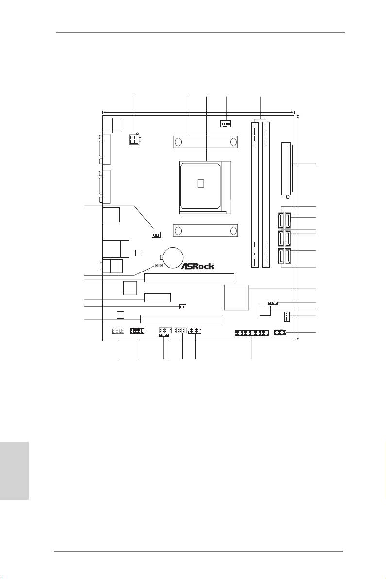
Motherboard Layout
CMOS
BATTE RY
Supe r
I/O
1 ATX 12V Power Connector (ATX12V1) 16 Chassis Fan Connector (CHA_FAN1)
2 CPU Heatsink Retention Module 17 System Panel Header (PANEL1)
3 CPU Socket 18 Print Port Header (LPT1)
4 CPU Fan Connector (CPU_FAN1) 19 USB 2.0 Header (USB4_5)
5 2 x 240-pin DDR3 DIMM Slots 20 USB 2.0 Header (USB8_9)
(Dual Channel: DDR3_A1, DDR3_B1) 21 USB 2.0 Header (USB6_7)
6 ATX Power Connector (ATXPWR1) 22 Consumer Infrared Module Header (CIR1)
7 SATA2 Connector (SATA_1) 23 COM Port Header (COM1)
English
8 SATA2 Connector (SATA_2) 24 Front Panel Audio Header (HD_AUDIO1)
9 SATA2 Connector (SATA_3) 25 PCI Slot (PCI1)
10 SATA2 Connector (SATA_4) 26 Infrared Module Header (IR1)
11 SATA2 Connector (SATA_6) 27 PCI Express 2.0 x1 Slot (PCIE2)
12 SATA2 Connector (SATA_5) 28 PCI Express 2.0 x16 Slot (PCIE1)
13 Southbridge Controller 29 Clear CMOS Jumper (CLRCMOS1)
14 Chassis Speaker Header (SPEAKER1) 30 Power Fan Connector (PWR_FAN1)
15 SPI Flash Memory (64Mb)
2
ASRock FM2A55M-DGS Motherboard
1
2
3
4
5
19.3cm (7.6-in)
Keyb oa rd
Mouse
PS2
PS2
FM2A55M—DGS
CPU _FAN 1
VGA1
ATX1 2V1
Fast US B
X
DDR3 2400+
6
SOCKET FM2
Fast LA N
DVI1
X
FSB8 00
ATXPWR1
22.6cm (8.9-in)
30
7
USB 2.0
T: USB 0
B: USB1
8
SATA_1
SATA_2
DDR3_A1 (64 bit , 240-pin module)
DDR3_B1 (64 bit , 240-pin module)
PWR_ FAN1
9
10
SATA_3
SATA_4
RJ-4 5 LAN
USB 2.0
X
Fast RA M
DX11
ErP/EuP Ready
T: USB2
B: USB3
11
LAN
SATA_5
SATA_6
MIC IN
Bot tom :
FRO NT
Cen ter :
LIN E IN
Top:
Dual Graphics
1
CLR C MOS 1
12
29
PCIE1
28
13
AMD
A55 FCH
Ro HS
PCIE2
27
(Hudson—D2)
SPEA KER 1
IR1
Chipset
1
14
26
1
64Mb
15
AUD IO
BIOS
COD EC
16
25
PCI1
CHA _FAN 1
HD_ AUDI O1
COM1
USB 6_7
USB 8_9
USB 4_5
PLED PWRBTN
1
1
1
1
1
1
1
1
17
CIR1
LPT 1
PANEL 1
HDLE D RESET
24
23
22
21
20
1819
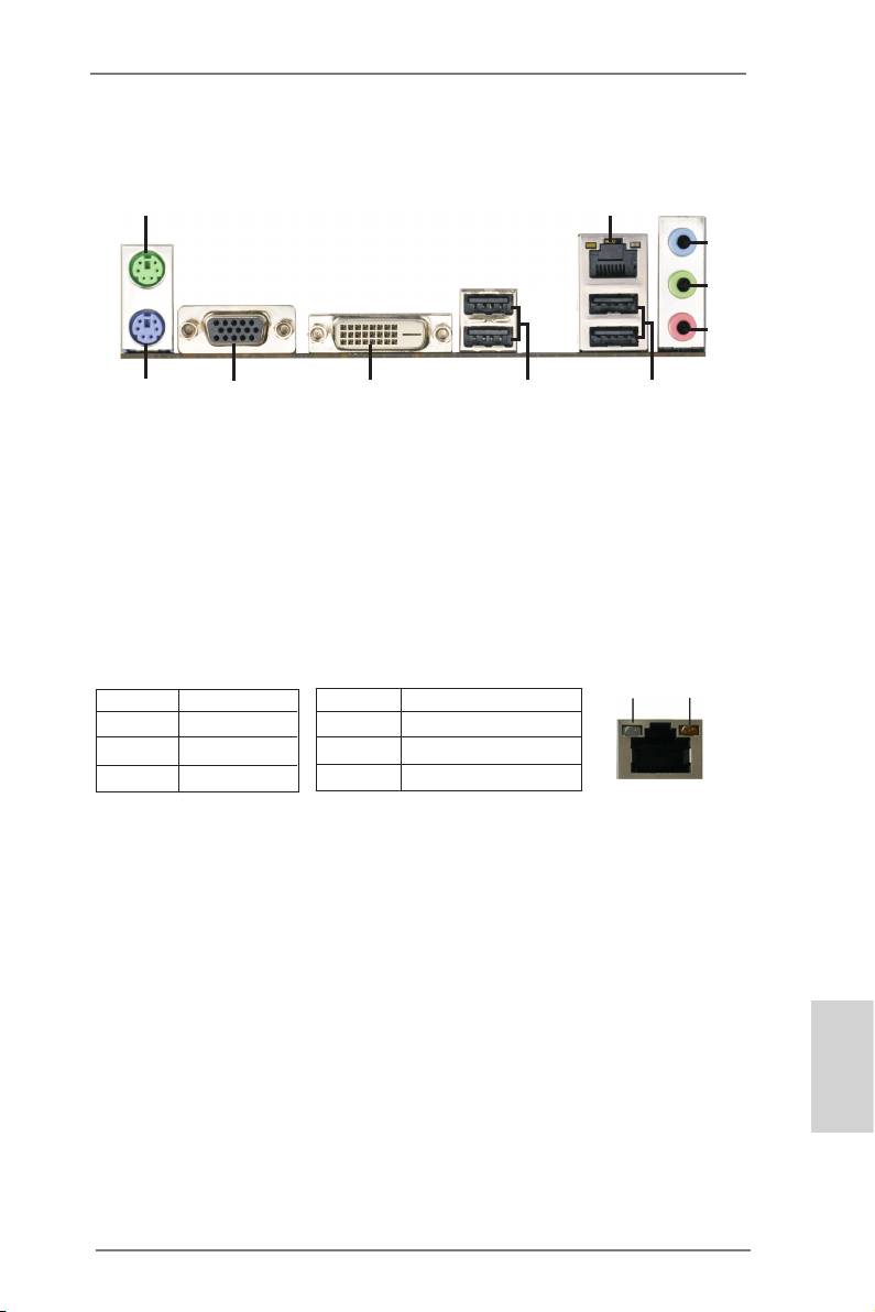
I/O Panel
1
2
3
4
5
910
8
7
6
1 PS/2 Mouse Port (Green) 6 USB 2.0 Ports (USB23)
* 2 LAN RJ-45 Port 7 USB 2.0 Ports (USB01)
3 Line In (Light Blue) 8 DVI-D Port (DVI1)
** 4 Front Speaker (Lime) 9 D-Sub Port (VGA1)
5 Microphone (Pink) 10 PS/2 Keyboard Port (Purple)
* There are two LED next to the LAN port. Please refer to the table below for the LAN port LED
indications.
LAN Port LED Indications
ACT/LINK
SPEED
Activity/Link LED SPEED LED
LED
LED
Status Description Status Description
Off No Link Off 10Mbps connection
Blinking Data Activity Orange 100Mbps connection
On Link Green 1Gbps connection
LAN Port
** To enable Multi-Streaming function, you need to connect a front panel audio cable to the front
panel audio header. Please refer to below steps for the software setting of Multi-Streaming.
®
TM
For Windows
7 / Vista
:
After restarting your computer, please double-click “Realtek HD Audio Manager” on the
system tray. Set “Speaker Conguration” to “Quadraphonic” or “Stereo”. Click “Device
advanced settings”, choose “Make front and rear output devices playbacks two different audio
streams simultaneously”, and click “ok”. Then reboot your system.
English
3
ASRock FM2A55M-DGS Motherboard
-
Page 1: Asrock FM2A55M-DGS
1 FM2A55M-DGS User Manual V ersion 1.0 Published August 2012 Copyright©2012 ASRock INC. All rights reserved.[…]
-
Page 2: Asrock FM2A55M-DGS
2 Copyright Notice: No part of this manual may be reproduced, transcribed, transmitted, or translated in any language, in any form or by any means, except duplication of documentation by the purchaser for backup purpose, without written consent of ASRock Inc. Products and corporate names appearing in this manual may or may not be regis- tered trade[…]
-
Page 3: Asrock FM2A55M-DGS
3 Contents 1. Introduction ………………………………………………………. 5 1.1 Package Contents ………………………………………………… ………… 5 1.2 Specications ………………………………………………………………….. 6 1.3 Unique Features ……………………………………[…]
-
Page 4: Asrock FM2A55M-DGS
4 3. UEFI SETUP UTILITY ………………………………………….. 37 3.1 Introduction …………………………………………………………………….. 37 3.1.1 UEFI Menu Bar ………………………………………………………. 37 3.1.2 Navigation Keys …………………………………………………….[…]
-
Page 5: Asrock FM2A55M-DGS
5 1. Introduction Thank you for purchasing ASRock FM2A55M-DGS motherboard, a reliable moth- erboard produced under ASRock’s consistently stringent quality control. It delivers excellent performance with robust design conforming to ASRock’s comm itment to quality and endurance. In this manual, chapter 1 and 2 contain introduction of the motherbo[…]
-
Page 6: Asrock FM2A55M-DGS
6 1.2 Specications Platform — Micro A TX Form Factor: 8.9-in x 7.6-in, 22.6 cm x 19.3 cm — Solid Capacitor for CPU power CPU — Support for Socket FM2 100W processors — Supports AMD’s Cool ‘n’ Quiet TM T echnology — UMI-Link GEN2 Chipset — AMD A55 FCH (Hudson-D2) Memory — Dual Channel DDR3 Memory T echnology — 2 x DDR3 DIMM slots — Support […]
-
Page 7: Asrock FM2A55M-DGS
7 Rear Panel I/O I/O Panel — 1 x PS/2 Mouse/Keyboard Port — 1 x D-Sub Port — 1 x DVI-D Port — 4 x Ready-to-Use USB 2.0 Ports — 1 x RJ-45 LAN Port with LED (ACT/LINK LED and SPEED LED) — HD Audio Jack: Line in / Front Speaker / Microphone Connector — 6 x SA T A2 3.0 Gb/s connectors, support RAID (RAID 0, RAID 1 and RAID 10), NCQ, AHCI and “Hot Plu[…]
-
Page 8: Asrock FM2A55M-DGS
8 W ARNING Please realize that there is a certain risk involved with overclocking, including adjusting the setting in the BIOS, applying Untied Overclocking T echnology , or using third-party overclocking tools. Overclocking may affect your system’ s stability , or even cause damage to the components and devices of your system. It should be done […]
-
Page 9: Asrock FM2A55M-DGS
9 1.3 Unique Features ASRock Extreme T uning Utility (AXTU) A SRock Extre me T uning Utility (AXTU) is an all-in-o ne tool to ne-tu ne di f fe rent syste m fun ctions in a user -friendly inter face, whic h in clude s Ha rdware Moni tor , Fa n Co ntrol, Over clocki ng, OC DNA, IES and XFast RAM. In Hardware Monitor , it shows the major readings of y[…]
-
Page 10: Asrock FM2A55M-DGS
10 ASRock APP Charger I f y o u d es i r e a f as t e r, l e ss r e s tr i c te d w a y o f c h a rg i n g y o u r Apple device s, suc h as iPhone /iPad/iPo d T ouch, ASRock has prepared a wonderful solution for you — ASRock APP Charger . Si mpl y in sta ll t he AP P C har ge r d riv er, i t m ake s y ou r i Pho ne charge much quickly from your com[…]
-
Page 11: Asrock FM2A55M-DGS
1 1 ASRock Crashless BIOS AS Ro ck Cr as hl es s B IO S a ll ow s u se rs to up da te th ei r B IO S without fear of failing. If power loss occurs during the BIOS up- date process, ASRock Crashless BIOS will automatically nish the BIOS update procedu[…]
-
Page 12: Asrock FM2A55M-DGS
12 ASRock Interactive UEFI A SR oc k I nt er act iv e U EF I i s a b len d of sy st em c on fig ur at io n to ol s , c oo l s ou nd ef fe ct s a nd s tu n ni ng v is ua ls . T he u np re c- edented UEFI provides a more attractive interface and bringsa lotmore[…]
-
Page 13: Asrock FM2A55M-DGS
13 1.4 Motherboard Layout 1 A TX 12V Power Connector (A TX12V1) 16 Chassis Fan Connector (CHA_F AN1) 2 CPU Heatsink Retention Module 17 System Panel Header (P ANEL1) 3 CPU Socket 18 Print Port Header (LPT1) 4 CPU Fan Connector (CPU_F AN1) 19 USB 2.0 Header (USB4_5) 5 2 x 240-pin DDR3 DIMM Slots 20 USB 2.0 Header (USB8_9) (Dual Channel: DDR3_A1, DDR[…]
-
Page 14: Asrock FM2A55M-DGS
14 1.5 I/O Panel * There are two LED next to the LAN port. Please refer to the table below for the LAN port LED indications. LAN Port LED Indications Activity/Link LED SPEED LED Status Description Status Description Off No Link Of f 10Mbps connection Blinking Data Activity Orange 100Mbps connection On Link Green 1Gbps connection 1 PS/2 Mouse Port ([…]
-
Page 15: Asrock FM2A55M-DGS
15 2. Installation This is a Micro A TX form factor (8.9-in x 7.6-in, 22.6 cm x 19.3 cm) motherboard. Before you install the motherboa rd, study the conguration of your chassis to ensure that the motherboard ts into it. Pre-installation Precautions T ak e no te of th e fo llo wing pr ecau tio ns be fore you ins tal l m othe rbo ard components[…]
-
Page 16: Asrock FM2A55M-DGS
16 2.1 CPU Installation Step 1. Unlock the socket by lifting the lever up to a 90 o angle. Step 2. Position the CPU directly above the socket such that the CPU corner with the golden triangle matches the socket corner with a small triangle. Step 3. Carefully insert the CPU into the socket until it ts in place. The CPU ts only in one correct o[…]
-
Page 17: Asrock FM2A55M-DGS
17 2.3 Installation of Memory Modules (DIMM) This mot herboar d pr ovides t wo 2 40-pin D DR3 (Dou ble Data R ate 3) DI MM slots , and su pport s Dual C hannel M emory T ec hnolog y . F or dua l chan nel co nfigu ratio n, yo u alw ays n eed to i nst all tw o ide nti cal (t he sa me b ran d, s peed , si ze a nd ch ip- type) memory modules in the DDR[…]
-
Page 18: Asrock FM2A55M-DGS
18 2.4 Expansion Slots (PCI and PCI Express Slots) There is 1 PCI slot and 2 PCI Express slots on this motherboard. PCI Slots: PCI slots are used to install expansion cards that have the 32-bit PCI interface. PCIE Slots: PCIE1 (PCIE x16 slot) is used for PCI Express x16 lane width graphics cards. PCIE2 (PCIE x1 slot) is used for PCI Express cards w[…]
-
Page 19: Asrock FM2A55M-DGS
19 2.5 AMD Dual Graphics Operation Guide This motherboard supports AMD Dual Graphics feature. AMD Dual Graphics brings multi-GPU performance capabilities by enabling an AMD A55 FCH (Hudson-D2) integrated graphics processor and a discrete graphics processor to operate simultaneously with combined output to a single display for blisteringly-fast fram[…]
-
Page 20: Asrock FM2A55M-DGS
20 * Dual Graphics appearing here is a registered trademark of AMD T echnologies Inc., and is used only for identication or explanation and to the owners’ benet, without intent to infringe. * For further information of AMD Dual Graphics technology , please check AMD website for up dates and details. Step 9. Click “Enable CrossFire TM ” […]
-
Page 21: Asrock FM2A55M-DGS
21 2. If you have installed onboard VGA driver from our support CD to your system already , you can freely enjoy the benets of dual monitor function after your system boots. If you haven’t installed onboard VGA driver yet, please install onboard VGA driver from our support CD to your system and restart your computer . 2.6 Dual Monitor and Surr[…]
-
Page 22: Asrock FM2A55M-DGS
22 Surround Display Feature This motherboard supports surround display upgrade. With the internal VGA output support (D-Sub and DVI-D) and external add-on PCI Express VGA cards, you can easily enjoy the benets of surround display feature. Please refer to the following steps to set up a surround display environment: 1. Install the PCI Express VGA[…]
-
Page 23: Asrock FM2A55M-DGS
23 For Windows ® 7 / 7 64-bit / Vista TM / Vista TM 64-bit OS: Right click the desktop, choose “Personalize”, and select the “Display Settings” tab so that you can adjust the parameters of the multi-monitor according to the steps below . A. Click the number ”2” icon. B. Cli ck the ite ms “ Thi s is my ma in m oni tor” an d “E xte[…]
-
Page 24: Asrock FM2A55M-DGS
24 USB 2.0 header (9-pin, black) CIR header (4-pin, gray) 2.7 ASRock Smart Remote Installation Guide AS Roc k S mar t Re mot e i s o nly u sed fo r AS Roc k m oth erb oar d wi th C IR he ade r . Plea se ref er to b elow pr ocedur es for th e q uick i nstall ation a nd usa ge of ASR ock Smart Remote. Step1. Find the CIR header located next to the US[…]
-
Page 25: Asrock FM2A55M-DGS
25 * ASRock Smart Remote is only supported by some of ASRock motherboards. Please refer to ASRock website for the motherboard support list: http://www .asrock.com 1. Only one of the front USB port can support CIR function. When the CIR function is enabled, the other port will remain USB function. 2. Multi-Angle CIR Receiver is used for front USB on[…]
-
Page 26: Asrock FM2A55M-DGS
26 2.8 Jumpers Setup T h e i l l u s t r a t io n s h o w s h o w j u m p e r s a r e setup. When the jumper cap is placed on pins, the jumper is “Short”. If no jumper cap is placed on pins, the jumper is “Open”. The i l lu s t r at i o n s h ow s a 3 — pi n j u m p er w h os e pin1 and pin2 are “Short” when jumper cap is placed on thes[…]
-
Page 27: Asrock FM2A55M-DGS
27 2.9 Onboard Headers and Connectors Onboar d headers and con nectors a re NOT jum pers. Do NOT place jumper caps over these headers and connectors. Placing jumper caps over the headers and connectors will cause permanent damage of the motherboard! Serial A T A2 Connectors These six Serial A T A2 (SA T A_1: see p.13, No. 7) (SA T A2) connectors su[…]
-
Page 28: Asrock FM2A55M-DGS
28 Infrared Module Header This header supports an (5-pin IR1) optional wireless transmitting (see p.13 No. 26) and receiving infrared module. Front Panel Audio Header This is an interface for the front (9-pin HD_AUDIO1) panel audio cable that allows (see p.13 No. 24) convenient connection and control of audio devices. Consumer Infrared Module Heade[…]
-
Page 29: Asrock FM2A55M-DGS
29 Chassis Speaker Header Please connect the chassis (4-pin SPEAKER 1) speaker to this header . (see p.13 No. 14) System Panel Header This header accommodates (9-pin P ANEL1) several system front panel (see p.13 No. 17) functions. Connect the po wer switch , reset switc h and s ystem stat us indica tor on the chassis to this header according to the[…]
-
Page 30: Asrock FM2A55M-DGS
30 CPU Fan Connectors Please connect the CPU fan (4-pin CPU_F AN1) cable to the connector and (see p.13 No. 4) match the black wire to the ground pin. Though this motherboard provides 4-Pin CPU fan (Quiet Fan) support, the 3-Pin CPU fan still can work successfully even without the fan speed control function. If you plan to connect the 3-Pin CPU fan[…]
-
Page 31: Asrock FM2A55M-DGS
31 2.10 Serial A T A2 (SA T A2) Hard Disks Installation This motherboard adopts AMD A55 FCH (Hudson-D2) chipset that supports Serial A T A2 (SA T A2) hard disks and RAID (RAID 0, RAID 1 and RAID 10) functions. Y ou may install SA T A3 hard disks on this motherboard for internal storage devices. This section will guide you to install the SA T A2 har[…]
-
Page 32: Asrock FM2A55M-DGS
32 Caution 1. Without SA T A 15-pin power connector interface, the SA T A2 Hot Plug cannot be processed. 2. Even some SA T A2 HDDs provide both SA T A 15-pin power connector and IDE 1×4-pin conventional power connector interfaces, the IDE 1×4-pin conventional power connector interface is denitely not able to support Hot Plug and will cause the H[…]
-
Page 33: Asrock FM2A55M-DGS
33 How to Hot Plug a SA T A2 HDD: Points of attention, before you process the Hot Plug: Please do follow below instruction sequence to process the Hot Plug, improper procedure will cause the SA T A2 HDD damage and data loss. Connect SA T A 15-pin power cable connector (Black) end to SA T A2 HDD. How to Hot Unplug a SA T A2 HDD: Points of attention,[…]
-
Page 34: Asrock FM2A55M-DGS
34 2.13 Driver Installation Guide T o install the drivers to your system, please insert the support CD to your optical drive rst. Then, the drivers compatible to your system can be auto-detected and listed on the support CD driver page. Please follow the order from up to bottom side to install those required drivers. Therefore, the drivers you i[…]
-
Page 35: Asrock FM2A55M-DGS
35 Using SA T A2 HDDs without NCQ and Hot Plug functions (IDE mode) STEP 1: Set up UEFI. A. Enter UEFI SETUP UTILITY Advanced screen Storage Conguration. B. Set the “SA T A Mode” option to [IDE]. STEP 2: Install Windows ® XP OS on your system. 2.15 Installing Windows ® 7 / 7 64-bit / Vista TM / Vista TM 64-bit / XP W ithout RAID Functions […]
-
Page 36: Asrock FM2A55M-DGS
36 STEP 1: Set up UEFI. A. Enter UEFI SETUP UTILITY Advanced screen Storage Conguration. B. Set the “SA T A Mode” option to [IDE]. STEP 2: Install Windows ® 7 / 7 64-bit / Vista TM / Vista TM 64-bit OS on your system. Using SA T A2 HDDs without NCQ and Hot Plug functions (IDE mode) 2.15.2 Installing Windows ® 7 / 7 64-bit / Vista TM / Vist[…]
-
Page 37: Asrock FM2A55M-DGS
37 3. UEFI SETUP UTILITY 3.1 Introduction ASRock Inter active UEF I is a blend of syst em congu ration to ols, cool sound ef- fects and stunning visuals. Not only will it make BIOS setup less difcult but also a lot more amusing. This section explains how to use the UEFI SETUP UTILITY to congure your system. The UEFI chip on the motherboard[…]
-
Page 38: Asrock FM2A55M-DGS
38 3.1.2 Navigation Keys Please check the following table for the function description of each navigation key . Navigation Key(s) Function Description / Moves cursor left or right to select Screens / Moves cursor up or down to select items + / — T o change option for the selected items <T ab> Switch to next function <Enter> T o bring up[…]
-
Page 39: Asrock FM2A55M-DGS
39 3.3 OC T weaker Screen In the OC T weaker screen, you can set up overclocking features. EZ OC Mode Y ou can use this option to adjust EZ overclocking setting. Please note that overclocing may cause damage to your components and motherboard. It should be done at your own risk and expense. CPU Conguration Overclock Mode U se th is to se le ct O[…]
-
Page 40: Asrock FM2A55M-DGS
40 Multiplier/V oltage Change This item is set to [Auto] by default. If it is set to [Manual], you may adjust the value of Processor Frequency and Processor V oltage. However , it is recommended to keep the default value for system stability . Boost Frequency Multiplier For safety and system stability , it is not recommended to adjust the value of […]
-
Page 41: Asrock FM2A55M-DGS
41 DRAM Timing Control Power Down Enable Use this item to enable or disable DDR power down mode. Bank Interleaving Interleaving allows memory accesses to be spread out over banks on the same node, or accross nodes, decreasing access contention. Channel Interleaving It allo ws you to enab le Cha nnel M emory Interl eaving. Con guration op- tions:[…]
-
Page 42: Asrock FM2A55M-DGS
42 RAS# Cycle Time (tRC) Use this item to change RAS# Cycle T ime (tRC) Auto/Manual setting. The default is [Auto]. Write Recovery T ime (tWR) Use this item to change Write Recovery Time (tWR) Auto/Manual setting. The default is [Auto]. Refresh Cyle Time (tRFC) Use this item to change Refresh Cyle T ime (tRFC) Auto/Manual setting. The default is [A[…]
-
Page 43: Asrock FM2A55M-DGS
43 3.4 Advanced Screen In this section, you may set the congurations for the following items: CPU Congu- ration, Nouth Bridge Conguration, South Bridge Conguration, Storage Congura- tion, Super IO Conguration, ACPI Conguration, USB Conguration and Network Conguration. Setting wrong values in this section may cause the sys[…]
-
Page 44: Asrock FM2A55M-DGS
44 3.4.1 CPU Conguration Core C6 Mode Use this item to enable or disable Core C6 mode. The default value is [Enabled]. Package C6 Mode This item appears only when you enable the item “Core C6 Mode”. Use this item to enable or disable Package C6 mode. The default value is [Dis- abled]. Cool ‘n’ Quiet Use this item to enable or disable[…]
-
Page 45: Asrock FM2A55M-DGS
45 3.4.2 North Bridge Conguration Primary Graphics Adapter This item will switch the PCI Bus scanning order while searching for video card. It allows you to select the type of Primary VGA in case of multiple video controllers. The default value of this feature is [PCI Express]. Con- guration options: [Onboard], [PCI] and [PCI Express]. Share […]
-
Page 46: Asrock FM2A55M-DGS
46 3.4.3 South Bridge Conguration Onboard HD Audio Select [Auto], [Enabled] or [Disabled] for the onboard HD Audio feature. If you select [Auto], the onboard HD Audio will be disabled when PCI Sound Card is plugged. Front Panel Select [Auto] or [Disabled] for the onboard HD Audio Front Panel. Onboard LAN This allows you to enable or disable the […]
-
Page 47: Asrock FM2A55M-DGS
47 3.4.4 Storage Conguration SA T A Controller Use this item to enable or disable the “SA T A Controller” feature. SA T A Mode Use th is item t o adjust SA T A Mode. The d efault va lue of th is option is [AHCI Mode]. Conguration options: [AHCI Mode], [RAID Mode] and [IDE Mode]. If you set this item to RAID mode, it is suggested to instal[…]
-
Page 48: Asrock FM2A55M-DGS
48 3.4.5 Super IO Conguration Serial Port Use this item to enable or disable the onboard serial port. Serial Port Address Use this item to set the address for the onboard serial port. Conguration options: [3F8h / IRQ4] and [3E8h / IRQ4]. Infrared Port Use this item to enable or disable the onboard infrared port. Infrared Port Address Use this[…]
-
Page 49: Asrock FM2A55M-DGS
49 3.4.6 ACPI Conguration Suspend to RAM Use this item to select whether to auto-detect or disable the Suspend-to- RAM feature. Select [Auto] will enable this feature if the OS supports it. Check Ready Bit Use this item to enable or disable the feature Check Ready Bit. Restore on AC/Power Loss This allows you to set the power state after an unex[…]
-
Page 50: Asrock FM2A55M-DGS
50 USB Mouse Power On Use this item to enable or disable USB Mouse to power on the system. ACPI HPET table Use this item to enable or disable ACPI HPET T able. The default value is [Enabled]. Please set this option to [Enabled] if you plan to use this moth- erboard to submit Windows ® Vista TM certication.[…]
-
Page 51: Asrock FM2A55M-DGS
51 3.4.7 USB Conguration USB 2.0 Controller Use this item to enable or disable the use of USB 2.0 controller . Legacy USB Support Use this option to select legacy support for USB devices. There are four con guration options: [Enabled] , [Auto], [Disabled] and [UEFI Setup Only]. The default value is [Enabled]. Please refer to below description[…]
-
Page 52: Asrock FM2A55M-DGS
52 3.4.8 Network Conguration Internet Setting Use this item to set up the internet connection mode. Conguration options: [DHCP (Auto IP)] and [PPPOE]. UEFI Download Server Use this item to select UEFI rmware download server for Internet Flash. Conguration options: [Asia], [Europe], [USA] and [China].[…]
-
Page 53: Asrock FM2A55M-DGS
53 3.5 T ool Sound Effect Enable or disable sound effects in the setup utility . System Browser System Browser can let you easily check your current system congura- tion in UEFI setup. OMG(Online Management Guard) Administrators are able to establish an internet curfew or restrict internet access at specied times via OMG. Y ou may schedule th[…]
-
Page 54: Asrock FM2A55M-DGS
54 Internet Flash Int erne t F lash sea rche s f or av aila ble UE FI fi rmwa re up date s fr om ou r servers. In other words, the system can auto-detect the latest UEFI from our servers and ash them without entering Windows OS. Please note that you must be running on a DHCP congured computer in order to en- able this function. Would you like[…]
-
Page 55: Asrock FM2A55M-DGS
55 CPU Fan 1 Setting This allows you to set the CPU fan 1 speed. Con guration options: [Full On] and [Automatic Mode]. The default is value [Full On]. Chassis Fan 1 Setting This allows you t o set the chassis fan 1 speed. Con guration options: [Full On], [Manual Mode] and [Automatic Mode]. The default is value [Full On]. Over T emperature Pro[…]
-
Page 56: Asrock FM2A55M-DGS
56 3.7 Boot Screen In this section, it will display the available devices on your system for you to cong- ure the boot settings and the boot priority . Setup Prompt Timeout T h is s h o w s t h e n u m b er o f s e c o n ds t o w a i t f o r s e t u p a c t i v at i o n k e y . 65535(0xFFFF) means inde nite waiting. Bootup Num-Lock If this it[…]
-
Page 57: Asrock FM2A55M-DGS
57 CSM parameters Launch Video OpROM policy Use this to control the execution of UEFI and Legacy Video OpROM. The default value is [Legacy only].[…]
-
Page 58: Asrock FM2A55M-DGS
58 3.8 Security Screen In this section, you may set or change the supervisor/user password for the system. For the user password, you may also clear it. Secure Boot Control Use this t o enabl e or d isable Secure B oot Con trol. The d efault value is [Enabled]. Secure Boot Policy Internal FV Image Execution Policy on Security Violation. Image load […]
-
Page 59: Asrock FM2A55M-DGS
59 Fixed Media The default value is [Deny Execute]. Key Management[…]
-
Page 60: Asrock FM2A55M-DGS
60 3.9 Exit Screen Save Changes and Exit When you select this option, it will pop-out the following message, “Save conguration changes and exit setup?” Select [OK] to save the changes and exit the UEFI SETUP UTILITY . Discard Changes and Exit When y ou select this op tion, it will pop- out the f ollowing message, “Discard changes and exit […]
-
Page 61: Asrock FM2A55M-DGS
61 4. Software Support 4.1 Install Operating System T hi s m o t he r b oa r d s u pp o r ts v a ri o u s M i c ro s o ft ® W i nd o w s ® o p er a t in g s y s te m s : 7 / 7 6 4- b it / V is ta TM / Vi s ta TM 6 4- bi t / X P S P 3. B ec au se mo t he rb oa rd se t ti ng s and h ardware o ptions v ary , u se t he se tup proc edures i n thi s ch[…]
-
Page 62: Asrock FM2A55M-DGS
62 Installing OS on a HDD Larger Than 2TB This motherboard is adopting UEFI BIOS that allows Windows ® OS to be installed on a large size HDD (>2TB). Please follow below procedure to install the operating system. 1. Please make sure to use Windows ® Vista TM 64-bit (with SP1 or above) or Windows ® 7 64-bit . 2. Press <F2> or <Delete&[…]
-
Page 63: Asrock FM2A55M-DGS
63 Installing OS on a HDD Larger Than 2TB in RAID Mode This motherboard is adopting UEFI BIOS that allows Windows ® OS to be installed on a large size HDD (>2TB). Please follow below procedure to install the operating system. 1. Please make sure to use Windows ® Vista TM 64-bit (with SP1 or above) or Windows ® 7 64-bit . 2. Press <F2> o[…]
-
Page 64: Asrock FM2A55M-DGS
64 7. And then key in drvcfg –s [Drv number] [Ctrl number] to enter Raid Utility . For example: key in drvcfg –s 4E B5 . 8. Choose Logical Drive Main Menu to set up Raid Drive. 9. Choose Logical Drive Create Menu to create a Raid Drive. 10. Choose Usable Physical Drive List to select Raid HDD.[…]
-
Page 65: Asrock FM2A55M-DGS
65 1 1. Press Space on keyboard to toggle checkbox. 12. Choose Ld Size setting , and key in the Raid size. 13. After set up Raid size, please click Start to Create . 14. Press <F10> to exit Utility . 15. During reboot, please press <F1 1> to enter Boot Manual. Choose UEFI: SCSI CD/DVD Drive . * This option only shows on Windows ® 7 64-[…]
-
Page 66: Asrock FM2A55M-DGS
66 16. Follow Windows ® Installation Guide to install OS. If you install Windows ® 7 64-bit / V ista TM 64-bit in a large hard disk (ex. Disk volume > 2TB), it m ay take more time to boot into Window s ® or install driver/ utilities. If you encounter this problem, you will need to following instructions to x this problem. Windows ® Vista […]
-
Page 67: Asrock FM2A55M-DGS
67 B. Disable “V olume Shadow Copy” service. a. T ype “computer management” in the Start Menu, then press “Enter”. b. Go to “Ser vices and Applicati ons>Service s”; The n double cl ick “V olume Shadow Copy”. c. Set “Startup type” to “Disable” then Click “OK”.[…]
-
Page 68: Asrock FM2A55M-DGS
68 17. Finish. C. Reboot your system. D. After reboot, please start to install motherboard drivers and utilities. Windows ® 7 64-bit: A. Please request the hotx KB2505454 thru this link: http://support.microsoft.com/kb/2505454/ B. After installing Windows ® 7 64-bit, install the hotx kb2505454. (This may take long time; >30 mins.) C. Reb[…]
На этой странице вы можете совершенно бесплатно скачать Руководство по эксплуатации ASRock FM2A55M-DGS.
У документа PDF Руководство по эксплуатации 67 страниц, а его размер составляет 16.51 Mb.
Читать онлайн Настольные компьютеры ASRock FM2A55M-DGS Руководство по эксплуатации
Скачать файл PDF «ASRock FM2A55M-DGS Руководство по эксплуатации» (16.51 Mb)
Популярность:
2044 просмотры
Подсчет страниц:
67 страницы
Тип файла:
Размер файла:
16.51 Mb