
")
BASE CONTROLLER ES4000. Оригинальная запчасть Атлас Копко для устранения неполадок в системе управления компрессорного оборудования.
Подробнее
В связи с ростом курса валют актуальность цены уточняйте у менеджеров.
В связи с ростом курса валют актуальность цены уточняйте у менеджеров.
Характеристики
|
|
Atlas Copco |
|
|
Бельгия |
|
|
ES4000 BASE |
|
|
элемент |
|
|
для воздушного компрессора |
Показать все
Описание
Контроллер ES4000 BASE (2204135111)
Контроллер ES4000 BASE (2204135111) представляет собой один из базовых элементов управления компрессорной системой, который отвечает за введение ручных настроек в режим работы воздушного компрессора на производственной площадке.
Полное согласование с механизмами
Купить контроллер ES4000 BASE (2204135111) будет правильным решением, так как он запрограммирован на работу с данной моделью компрессорной техники. Это гарантирует полную корректность передаваемых команд.
Будьте всегда в курсе!
Узнавайте о скидках и акциях первым
Provide feedback
Saved searches
Use saved searches to filter your results more quickly
Sign up
Appearance settings
Chicago Pneumatic ES 4000 STANDARD Instruction
Browse or Download User Manual for Chicago Pneumatic ES 4000 STANDARD Controller: Chicago Pneumatic ES 4000 STANDARD Instruction (39 pages)
Specifications:
- Manufacturer: Chicago Pneumatic
- Category of Device: Controller
- Document: ES 4000 STANDARD Instruction, File Type: PDF
- Updated: 13-10-2022
- Count of Pages: 39
Download ES 4000 STANDARD Manual (39 pages)
Read Chicago Pneumatic ES 4000 STANDARD Manual Online (DOC-487bf8b2):
Chicago Pneumatic ES 4000 STANDARD Controller PDF Instruction (Updated: Thursday 13th of October 2022 02:17:57 PM)
Rating: 4.9 (rated by 79 users)
Compatible devices: 5276, poweradjust 3, Network LTC Plus, CP90600, DA-52, Sun StorEdge D1000, UVR61-3, DMX-100.
- SystemAir S-RVAZ4-24A Instruction (UPD: 06 Aug 2022, systemair/s-rvaz4-24a.pdf) (view)
- Kutai electronics ADVR-073 Operation manual (UPD: 10 Aug 2022, kutai-electronics/advr-073.pdf) (view)
- Sonos Connect Quick product manual (UPD: 21 Feb 2023, sonos/connect.pdf) (view)
- Magtrol DSP7000 Operation & user’s manual (UPD: 30 Dec 2022, magtrol/dsp7000.pdf) (view)
Text Version of Chicago Pneumatic ES 4000 STANDARD Manual: (Ocr-Read, UPD: 13 October 2022)
Similar Searches:
Related for Chicago Pneumatic ES 4000 STANDARD Manuals: GT10, QP Series, dTRANS pH 02
| № | Title | Device Model | Views | Downloads | #SysCode | Pages | |
|---|---|---|---|---|---|---|---|
| 1 |
JUMO dTRANS pH 02136 pages, #KXI561 |
dTRANS pH 02 | 634 | 108 | #KXI561 | 136 | |
| 2 |
PXM PX741#6ET4Z6 Controller User Manual, 34 pages |
PX741 | 1121 | 348 | #6ET4Z6 | 34 | |
| 3 |
Evco c-pro 3 OEMES 4000 STANDARD Compatible Documentation (#7R57AR, 38 pages) |
c-pro 3 OEM | 343 | 69 | #7R57AR | 38 | |
| 4 |
Siemens SKB32 SeriesController SKB32 Series User Manual, #1X474V — 7 pages |
SKB32 Series | 1102 | 474 | #1X474V | 7 | |
| 5 |
DRAGONFRAME DMC+ES 4000 STANDARD Compatible Manual (#82U6W1, 12 pages) |
DMC+ | 1200 | 384 | #82U6W1 | 12 | |
| 6 |
Sphere PWM Series13 pages, #TTWGV9 |
PWM Series | 880 | 458 | #TTWGV9 | 13 | |
| 7 |
Control Data FF524-AControl Data Documentation Controller FF524-A (72 pages) |
FF524-A | 321 | 113 | #4712P6 | 72 | |
| 8 |
ascon QP Series54 pages, #99Y7Z2 |
QP Series | 1489 | 760 | #99Y7Z2 | 54 |
Recommended for Viewing: Sedomat 5800, FI-5530C2, GSC470M-03, VITOCROSSAL 200
#79337L: VITOCROSSAL 200 Instructions manual
VITOCROSSAL 200, 72, viessmann/vitocrossal-200.pdf
Emerson Introduction manual: Copeland Scroll (#X3VT13)
Copeland Scroll, 52, emerson/copeland-scroll.pdf
HPI Racing Motorized Toy Car Manual (#F59F2L)
NITRP RS4 RTR3 EVO+, 60, hpi-racing/nitrp-rs4-rtr3-evo.pdf
Barco Specifications: Sedomat 5800 (#2SJ77P)
Sedomat 5800, 2, barco/sedomat-5800.pdf
#26MS2S: FI-5530C2 Operator’s manual
FI-5530C2, 168, fujitsu/fi-5530c2.pdf
#I6P75T: HD 8753 Service manual
HD 8753, 61, philips/hd-8753.pdf
GSC470M-03 Dishwasher — #4OZ4YN
GSC470M-03, 16, ge/gsc470m-03.pdf
AEX500 Musical Instrument — #23E95Y
AEX500, 6, yamaha/aex500.pdf
StudioComm 76DA
50241-1016, Issue 10© 2016 by Studio Technologies, Inc., all rights reserved www.studio-tech.comModel 76DA Central Controller andModel 77 Control ConsoleUser Guide Issue 10, October 2016This User Guide is applicable for systems consisting of:Model 76DA: serial number M76DA-01151 and later with software version 4.20 and higher and FPGA version 4.12 and higher;Model 77: serial number M77-00151 and .
76DA Recording Equipment 53
Bosch Rexroth Rho 4.0
Rexroth IndraControl VCP 20IndustrialHydraulicsElectric Drivesand Controls Linear Motion and Assembly Technologies PneumaticsServiceAutomationMobileHydraulicsRexroth Rho 4.0Connectivity manual1070072365Edition 04Project planning .
Rexroth Rho 4.0 Controller 81
Simon 8400700-0 Series
SLIDE CONTROLSLIDE CONTROL SLIDE CONTROL SLIDE CONTROL SLIDE CONTROL 990838 15-06-2015Caracteristicas Técnicas Caracteristicas Técnicas Caractéristiques Techiques Technical specifications Charakterystyka techniczna SIMON, S.A. Diputación, 390-392 / 080 .
8400700-0 Series Controller 2
DynaGen GSC400 Series
GSC400 Programmer and PC Interface User Manual Full Version File: GSC400 PC Interface Rev1.7.doc, September 2014 GSC400 Series GSC400 Programmer and PC Interface User Manual .
GSC400 Series Motherboard 44
Baumuller b maXX 5000 BM5800 Series
Instruction handbookRead the Instruction handbook before starting any work!Language EnglishTranslationDocument No. 5.16027.04Part No. 464136Edition 22-May-2019b maXX 5000BM5800Multi-axis controllerE5.16027.04 .
b maXX 5000 BM5800 Series Controller 176
Источник
Индикация неисправности на блоке управления
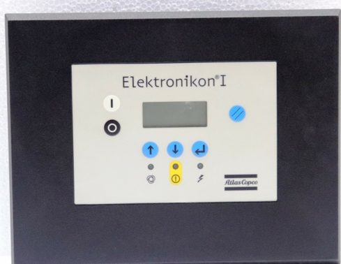
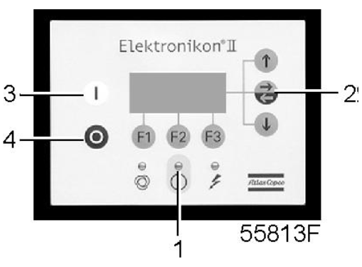
Atlas Copco Elektronikon II MkIV
Ceccato ES3000
Ceccato ES4000 mini
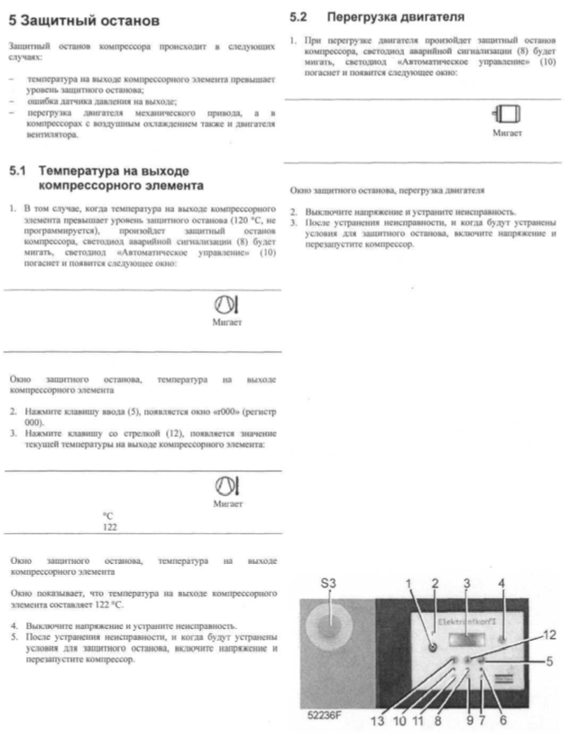
Компрессор будет остановлен:
- Если температура на выходе компрессорного элемента превысит уровень аварийного
останова (определяется датчиком температуры (TT11) или реле температуры
- В случае ошибки датчика давления на выходе (PT20) или датчика температуры
- В случае перегрузки электродвигателя компрессора (M1).
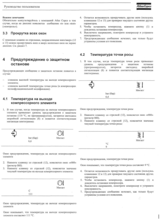
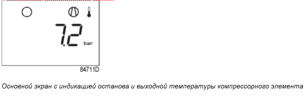
Температура воздуха на выходе компрессорного элемента
Если температура на выходе компрессорного элемента превышает уровень аварийного
останова (задан на заводе-производителе, 115 ˚C/239 ˚F):
- Компрессор будет остановлен.
- Светодиод аварийной сигнализации (5) будет мигать.
- Появится следующий экран:
- Соответствующий значок мигает.
- Прокручивайте с помощью кнопок со стрелками вверх или вниз (4-8), пока не отобразится текущая температура на выходе компрессорного элемента.
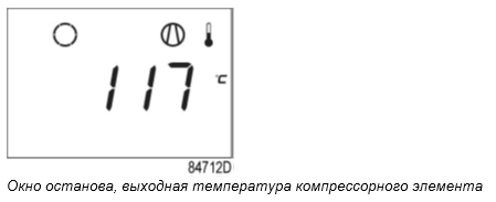
На экране отображается значение температуры на выходе компрессорного элемента —
- Устранив причину аварийного отключения, нажмите кнопку ввода (7) на 5 секунд.
- Когда на экране появляется , компрессор может быть перезапущен.
В случае перегрузки двигателя:
- Компрессор будет остановлен.
- Светодиод аварийной сигнализации (5) будет мигать.
- Появится следующий экран:
Основной экран с индикацией аварийного отключения вследствие перегрузки двигателя
- Свяжитесь с поставщиком для выполнения поиска и устранения неисправностей
- Устранив причину аварийного отключения, нажмите кнопку ввода (7) на 5 секунд.
- Когда на экране появляется , компрессор может быть перезапущен.
Ошибка датчика давления/температуры
В случае ошибки датчика давления на выходе (PT20) или датчика температуры (TT11):
- Компрессор будет остановлен.
- Появится следующий экран:
Источник
Es 4000 basic контроллер инструкция
Es 4000 basic контроллер инструкция
Винтовые компрессоры, осушители и фильтры
- Главная
- О компании
- Новости
- Каталог оборудования
- Услуги и сервис
- Вопросы и ответы
- Сертификаты
- Наши клиенты
- Контакты
- Винтовые компрессоры
- Серия CSL (0.22 — 1.63 м3/мин)
- Серия CSM MINI (0.24 — 1.00 м3/мин)
- Серия CSM MAXI (0.69 — 1.86 м3/мин)
- Серия CSA (0.49 — 2.00 м3/мин)
- Серия CSB (1.19 — 3.97 м3/мин)
- Серия CSC (3.48 — 7.80 м3/мин)
- Серия CSD (7.08 — 11.5 м3/мин)
- Серия DRB (3.50 — 5.93 м3/мин)
- Серия DRC (3.84 — 7.86 м3/мин)
- Серия DRD (7.20 — 12.5 м3/мин)
- Серия DRE (10.1 — 19.6 м3/мин)
- Серия DRF (13.5 — 30.0 м3/мин)
- Серия INVERTER
- Винтовые безмаслянные компрессоры
- Спиральные безмаслянные компрессоры
- Азотные генераторы
- Поршневые компрессоры
- Системы управления и мониторинга
- Холодильные осушители
- Адсорбционные осушители
- Магистральные фильтры
- Воздухосборники
- Разделители и отводчики конденсата
- Магистрали сжатого воздуха AIRnet
- Расходные материалы
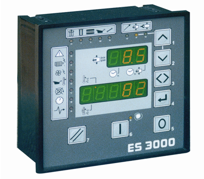
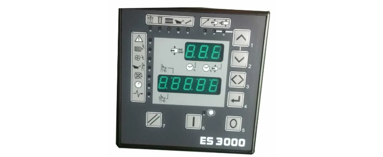
Электронный модуль управления ES 3000 c цифровым дисплеем
Контроллер ES 3000, устанавливаемый на винтовые компрессоры CSA, CSB, CSC, CSD — это современная управляющая система, специально разработанная для компрессоров средней и высокой производительности.
В устройстве применена клавиатура сенсорного типа, не боящаяся загрязнений. Контроллер имеет цифровые и аналоговые порты для подключения различных внешних устройств. Программное обеспечение контроллера позволяет осуществлять многоуровневый доступ к перепрограммированию параметров для специалистов разной квалификации. Имеется также защита от ввода заведомо нереальных или опасных параметров работы.
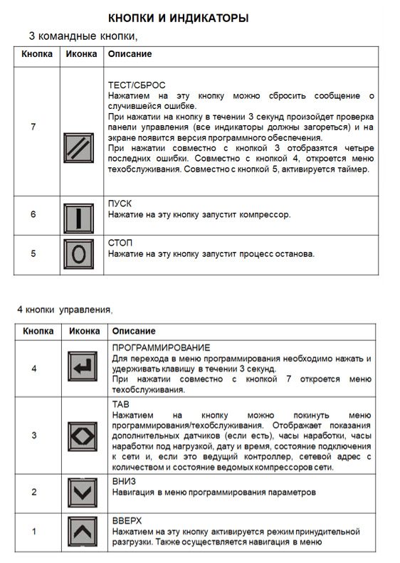
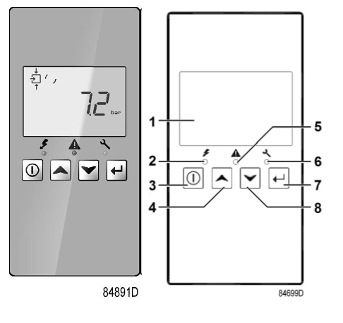
Кнопки и индикаторы ES3000
3 командные кнопки:
4 кнопки управления:
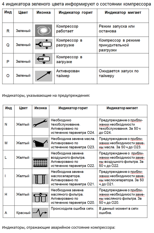
4 индикатора зеленого цвета информируют о состоянии компрессора:
6 индикаторов, указывающих на предупреждения:
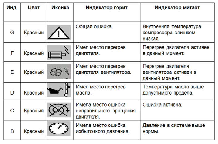
6 индикаторов, отражающих аварийное состояние компрессора:
Copyright © 2001-2020 | All Rights Reserved
Индикация ошибок на блоке управления Ceccato ES3000
Индикаторы отображающие различные уровни неисправностей компрессора
| Индикатор | Цвет | Обозначение | Горит | Мигает |
| N | Желтый | Необходимо общее техническое обслуживание. Истекло время, указанное в параметре 024. |
Приближается время общего технического обслуживания. Индикатор начинает мигать за 50 часов до истечения времени, указанного в параметре 024. |
|
| M | Желтый | Необходимо заменить масло. Истекло время, указанное в параметре 023. |
Приближается время замены масла. Индикатор начинает мигать за 50 часов до истечения времени, указанного в параметре 023. |
|
| L | Желтый | Необходимо заменить воздушный фильтр. Истекло время, указанное в параметре 022. | Приближается время замены воздушного фильтра. Индикатор начинает мигать за 50 часов до истечения времени, указанного в параметре 022. |
|
| I | Желтый | Необходимо заменить воздушно-масляный сепаратор. Истекло время, указанное в параметре 021. | Приближается время замены воздушно-масляного сепаратора. Индикатор начинает мигать за 50 часов до истечения времени, указанного в параметре 021. |
|
| H | Желтый | Необходимо заменить масляный фильтр. Истекло время, указанное в параметре 020. | Приближается время замены масляного фильтра. Индикатор начинает мигать за 50 часов до истечения времени, указанного в параметре 020. |
|
| A | Желтый | Неисправность в сети. | Неисправность в сети. |
Индикаторы отображающие аварийное состояние компрессора
| Индикатор | Цвет | Обозначение | Горит | Мигает |
| G | Красный | Общая неисправность. Сбой датчиков. | Слишком низкая температура внутри компрессора. | |
| F | Красный | Перегрузка главного двигателя. | Возникла перегрузка главного двигателя. | |
| E | Красный | Перегрузка двигателя вентилятора. | Возникла перегрузка двигателя вентилятора. | |
| D | Красный | Перегрев масла. | Происходит перегрев масла. | |
| C | Красный | Неправильное направление вращения. | Неправильное направление вращения. | |
| B | Красный | Избыточное давление. | Избыточное давление. |
В АВАРИЙНЫХ УСЛОВИЯХ состояние компрессора отображает экран:
Мигает индикатор G.
Верхний экран пуст.
На нижнем экране мигает значение температуры. Это означает, что температура внутри компрессора ниже, чем указано в параметре R17.
ОТОБРАЖЕНИЕ ПОСЛЕДНИХ ЧЕТЫРЕХ СИГНАЛОВ НЕИСПРАВНОСТИ
При одновременном нажатии кнопок 7 и 3 на панели отображаются последние четыре неисправности, которые привели к остановке компрессора. Верхний экран показывает три цифры. Первая и вторая цифры показывают год. когда произошла неисправность (02. 03. 04 и т.д.), или день недели (1=понедельник. 2=вторник и т.д.). Третья цифра показывает номер неисправности (0-3). Нижний экран показывает, соответственно, день и месяц или часы и минуты. На левой стороне горит индикатор, соответствующий возникшей неисправности.
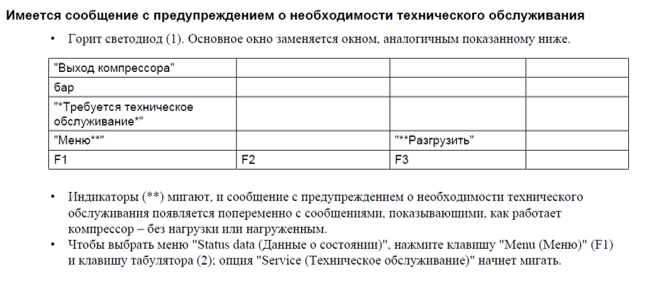
ОТОБРАЖЕНИЕ И СБРОС ПРЕДУПРЕЖДЕНИЙ О ТЕХНИЧЕСКОМ ОБСЛУЖИВАНИИ
Для просмотра и изменения времени до замены компонентов, подлежащих техническому обслуживанию, следует нажать и удерживать кнопки 7 и 4, пока не загорится индикатор Н.
С помощью кнопок 1 и 2 выберите компонент (для перемещения вперед используется кнопка 1, назад-кнопка 2).
Нижний экран покажет время эксплуатации в выбранного компонента (в часах).
Чтобы сбросить время эксплуатации, нажмите кнопку 4 — значение начнет мигать. Затем еще раз нажмите кнопку 4 -значение сбросится в 0.
Приведенная выше процедура применима для всех компонентов. Для выхода нажать кнопку 3.
ИНСТРУКЦИИ
Тахеометры SOKKIA
- Тахеометры Sokkia серии iM (pdf, 10 MB) (Модели iM-102, iM-102L, iM-103, iM-105, iM-105L, iM-52, iM-55)
- Тахеометры Sokkia серии CX (pdf, 16 MB) (Модели CX-102, CX-102L, CX-103, CX-105, CX-105L, CX-106)
- Тахеометры Sokkia серии FX (pdf, 8 MB) (Модели FX-101, FX-102, FX-105)
- Тахеометры Sokkia SET4110r (pdf, 2 MB) (Модель SET4110r)
- Тахеометры Sokkia серии SETx00 (pdf, 7 MB) (Модели SET300, SET300S, SET500, SET500S, SET600, SET600S,)
- Тахеометры Sokkia серии X30RK (pdf, 9 MB) (Модели SET230RK/RK3, SET330RK/RK3, SET530RK/RK3, SET630RK)
- Краткое справочное руководство FX – Functional X-ellence Station (pdf, 3 MB)
- Краткое справочное руководство DX – Direct aiming X-ellence (doc, 3.5 MB)
- Spectrum Link — Как передать файл из тахеометра через кабель (pdf, 2.44 MB)
- Spectrum Link — Конвертация файлов SDR-DXF-DWG-TXT (pdf, 4.4 MB)
Тахеометры TOPCON
- Тахеометры Topcon серии GT (pdf, 13.7 MB)
- Тахеометры Topcon серии GM (pdf, 3 MB) (Модели GM-102, GM-105, GM-52, GM-55)
- Тахеометры Topcon серии ES (pdf, 15 MB) (Модели ES-102, ES-102L, ES-103, ES-105, ES-105L)
- Тахеометры Topcon серии OS (pdf, 10 MB) (Модели OS-101L, OS-103L, OS-105L)
- Тахеометры Topcon серий GTS-750 и GPT-7500 (pdf, 9 MB) (Модели GTS-751, GTS-753, GTS-755, GPT-7501, GPT-7503, GPT-7505)
- Тахеометры Topcon серии GPT-3100N (pdf, 3 MB) (Модели GPT-3102N, GPT-3103N, GPT-3105N, GPT-3107N)
- Тахеометры Topcon серии GPT-3000N (pdf, 3 MB) (Модели GPT-3002N, GPT-3003N, GPT-3005N, GPT-3007N)
- Тахеометры Topcon серии GTS-100N (pdf, 3 MB) (Модели GTS-102N, GTS-105N)
- Краткое справочное руководство DS – Direct Aiming Station (doc, 3.5 MB)
- Краткое справочное руководство OS – On-board Total Station (doc, 3.5 MB)
- Topcon Link — Как передать файл из тахеометра через кабель (pdf, 2.44 MB)
- Topcon Link — Конвертация файлов SDR-DXF-DWG-TXT (pdf, 4.4 MB)
ГНСС оборудование
Полевые контроллеры Sokkia
Полевые контроллеры Topcon
Контроллеры ЭнерджиСейвер серии ES-T исп. IP20 УХЛ4
Новая серия контроллеров-оптимизаторов ЭнерджиСейвер ES-T
Отличительные особенности контроллеров-оптимизаторов серии ES-T (по сравнению с серией ESM) следующие:
- визуальное отображение текущего значения тока на LCD-дисплее, в том числе по трем фазам (опции)
- наличие режима управления насосами «скважина», имеющего в числе прочего функцию защиты от «сухого хода»
В базовом исполнении степень защиты устройств IP20, климатическое исполнение УХЛ4. Возможно исполнение защиты IP54, климатическое исполнение до УХЛ1.
Гарантийный срок на контроллеры-оптимизаторы серии ES-T составляет 3 года с возможностью увеличения до 4 или 5 лет. Оборудование в наличии либо сроки изготовления минимальны.
Система
менеджмента качества
сертифицирована по
ISO 9001:2008
Перейдите в разделы, приведенные ниже, выберите необходимое оборудование и положите его в корзину. — Преобразователи частоты
— Оборудование для плавного пуска
- ИЗДЕЛИЯ
- преобразователи частоты (частотные преобразователи, частотники)
- принцип действия
- структура частотников
- выбор преобразователя частоты
- пример применения преобразователей частоты с насосами
- пример применения станции управления насосами
- подбор преобразователя частоты
- оборудование для плавного пуска и энергосбережения
- устройства плавного пуска (УПП, плавные пускатели, мягкие пускатели, устройства мягкого пуска, софтстартеры)
- принцип действия
- плавный пуск насосов
- подбор устройств плавного пуска
- контроллеры ЭнерджиСейвер
- принцип действия
- области применения
- реализованные проекты
- отзывы
- контроллеры Powerboss
- примеры применения
- устройства плавного пуска (УПП, плавные пускатели, мягкие пускатели, устройства мягкого пуска, софтстартеры)
- преобразователи частоты (частотные преобразователи, частотники)
для преобразователей частоты серий ES022, ES024, ES025 и ES026
Источник
Контроллер ES 3000, устанавливаемый на винтовые компрессоры CSA, CSB, CSC, CSD — это современная управляющая система, специально разработанная для компрессоров средней и высокой производительности.
В устройстве применена клавиатура сенсорного типа, не боящаяся загрязнений. Контроллер имеет цифровые и аналоговые порты для подключения различных внешних устройств. Программное обеспечение контроллера позволяет осуществлять многоуровневый доступ к перепрограммированию параметров для специалистов разной квалификации. Имеется также защита от ввода заведомо нереальных или опасных параметров работы.
Кнопки и индикаторы ES3000
3 командные кнопки:
4 кнопки управления:
4 индикатора зеленого цвета информируют о состоянии компрессора:
6 индикаторов, указывающих на предупреждения:
6 индикаторов, отражающих аварийное состояние компрессора:
Copyright © 2001-2020 | All Rights Reserved
Источник
ИНСТРУКЦИИ
Тахеометры SOKKIA
- Тахеометры Sokkia серии iM (pdf, 10 MB) (Модели iM-102, iM-102L, iM-103, iM-105, iM-105L, iM-52, iM-55)
- Тахеометры Sokkia серии CX (pdf, 16 MB) (Модели CX-102, CX-102L, CX-103, CX-105, CX-105L, CX-106)
- Тахеометры Sokkia серии FX (pdf, 8 MB) (Модели FX-101, FX-102, FX-105)
- Тахеометры Sokkia SET4110r (pdf, 2 MB) (Модель SET4110r)
- Тахеометры Sokkia серии SETx00 (pdf, 7 MB) (Модели SET300, SET300S, SET500, SET500S, SET600, SET600S,)
- Тахеометры Sokkia серии X30RK (pdf, 9 MB) (Модели SET230RK/RK3, SET330RK/RK3, SET530RK/RK3, SET630RK)
- Краткое справочное руководство FX – Functional X-ellence Station (pdf, 3 MB)
- Краткое справочное руководство DX – Direct aiming X-ellence (doc, 3.5 MB)
- Spectrum Link — Как передать файл из тахеометра через кабель (pdf, 2.44 MB)
- Spectrum Link — Конвертация файлов SDR-DXF-DWG-TXT (pdf, 4.4 MB)
Тахеометры TOPCON
- Тахеометры Topcon серии GT (pdf, 13.7 MB)
- Тахеометры Topcon серии GM (pdf, 3 MB) (Модели GM-102, GM-105, GM-52, GM-55)
- Тахеометры Topcon серии ES (pdf, 15 MB) (Модели ES-102, ES-102L, ES-103, ES-105, ES-105L)
- Тахеометры Topcon серии OS (pdf, 10 MB) (Модели OS-101L, OS-103L, OS-105L)
- Тахеометры Topcon серий GTS-750 и GPT-7500 (pdf, 9 MB) (Модели GTS-751, GTS-753, GTS-755, GPT-7501, GPT-7503, GPT-7505)
- Тахеометры Topcon серии GPT-3100N (pdf, 3 MB) (Модели GPT-3102N, GPT-3103N, GPT-3105N, GPT-3107N)
- Тахеометры Topcon серии GPT-3000N (pdf, 3 MB) (Модели GPT-3002N, GPT-3003N, GPT-3005N, GPT-3007N)
- Тахеометры Topcon серии GTS-100N (pdf, 3 MB) (Модели GTS-102N, GTS-105N)
- Краткое справочное руководство DS – Direct Aiming Station (doc, 3.5 MB)
- Краткое справочное руководство OS – On-board Total Station (doc, 3.5 MB)
- Topcon Link — Как передать файл из тахеометра через кабель (pdf, 2.44 MB)
- Topcon Link — Конвертация файлов SDR-DXF-DWG-TXT (pdf, 4.4 MB)
ГНСС оборудование
Полевые контроллеры Sokkia
Полевые контроллеры Topcon
Источник
Контроллеры ЭнерджиСейвер серии ES-T исп. IP20 УХЛ4
Новая серия контроллеров-оптимизаторов ЭнерджиСейвер ES-T
Отличительные особенности контроллеров-оптимизаторов серии ES-T (по сравнению с серией ESM) следующие:
- визуальное отображение текущего значения тока на LCD-дисплее, в том числе по трем фазам (опции)
- наличие режима управления насосами «скважина», имеющего в числе прочего функцию защиты от «сухого хода»
В базовом исполнении степень защиты устройств IP20, климатическое исполнение УХЛ4. Возможно исполнение защиты IP54, климатическое исполнение до УХЛ1.
Гарантийный срок на контроллеры-оптимизаторы серии ES-T составляет 3 года с возможностью увеличения до 4 или 5 лет. Оборудование в наличии либо сроки изготовления минимальны.
Система
менеджмента качества
сертифицирована по
ISO 9001:2008
Перейдите в разделы, приведенные ниже, выберите необходимое оборудование и положите его в корзину. — Преобразователи частоты
— Оборудование для плавного пуска
- ИЗДЕЛИЯ
- преобразователи частоты (частотные преобразователи, частотники)
- принцип действия
- структура частотников
- выбор преобразователя частоты
- пример применения преобразователей частоты с насосами
- пример применения станции управления насосами
- подбор преобразователя частоты
- оборудование для плавного пуска и энергосбережения
- устройства плавного пуска (УПП, плавные пускатели, мягкие пускатели, устройства мягкого пуска, софтстартеры)
- принцип действия
- плавный пуск насосов
- подбор устройств плавного пуска
- контроллеры ЭнерджиСейвер
- принцип действия
- области применения
- реализованные проекты
- отзывы
- контроллеры Powerboss
- примеры применения
- устройства плавного пуска (УПП, плавные пускатели, мягкие пускатели, устройства мягкого пуска, софтстартеры)
- преобразователи частоты (частотные преобразователи, частотники)
для преобразователей частоты серий ES022, ES024, ES025 и ES026
Источник
Индикация ошибок на блоке управления Ceccato ES3000
Индикаторы отображающие различные уровни неисправностей компрессора
| Индикатор | Цвет | Обозначение | Горит | Мигает |
| N | Желтый | Необходимо общее техническое обслуживание. Истекло время, указанное в параметре 024. |
Приближается время общего технического обслуживания. Индикатор начинает мигать за 50 часов до истечения времени, указанного в параметре 024. |
|
| M | Желтый | Необходимо заменить масло. Истекло время, указанное в параметре 023. |
Приближается время замены масла. Индикатор начинает мигать за 50 часов до истечения времени, указанного в параметре 023. |
|
| L | Желтый | Необходимо заменить воздушный фильтр. Истекло время, указанное в параметре 022. | Приближается время замены воздушного фильтра. Индикатор начинает мигать за 50 часов до истечения времени, указанного в параметре 022. |
|
| I | Желтый | Необходимо заменить воздушно-масляный сепаратор. Истекло время, указанное в параметре 021. | Приближается время замены воздушно-масляного сепаратора. Индикатор начинает мигать за 50 часов до истечения времени, указанного в параметре 021. |
|
| H | Желтый | Необходимо заменить масляный фильтр. Истекло время, указанное в параметре 020. | Приближается время замены масляного фильтра. Индикатор начинает мигать за 50 часов до истечения времени, указанного в параметре 020. |
|
| A | Желтый | Неисправность в сети. | Неисправность в сети. |
Индикаторы отображающие аварийное состояние компрессора
| Индикатор | Цвет | Обозначение | Горит | Мигает |
| G | Красный | Общая неисправность. Сбой датчиков. | Слишком низкая температура внутри компрессора. | |
| F | Красный | Перегрузка главного двигателя. | Возникла перегрузка главного двигателя. | |
| E | Красный | Перегрузка двигателя вентилятора. | Возникла перегрузка двигателя вентилятора. | |
| D | Красный | Перегрев масла. | Происходит перегрев масла. | |
| C | Красный | Неправильное направление вращения. | Неправильное направление вращения. | |
| B | Красный | Избыточное давление. | Избыточное давление. |
В АВАРИЙНЫХ УСЛОВИЯХ состояние компрессора отображает экран:
Мигает индикатор G.
Верхний экран пуст.
На нижнем экране мигает значение температуры. Это означает, что температура внутри компрессора ниже, чем указано в параметре R17.
ОТОБРАЖЕНИЕ ПОСЛЕДНИХ ЧЕТЫРЕХ СИГНАЛОВ НЕИСПРАВНОСТИ
При одновременном нажатии кнопок 7 и 3 на панели отображаются последние четыре неисправности, которые привели к остановке компрессора. Верхний экран показывает три цифры. Первая и вторая цифры показывают год. когда произошла неисправность (02. 03. 04 и т.д.), или день недели (1=понедельник. 2=вторник и т.д.). Третья цифра показывает номер неисправности (0-3). Нижний экран показывает, соответственно, день и месяц или часы и минуты. На левой стороне горит индикатор, соответствующий возникшей неисправности.
ОТОБРАЖЕНИЕ И СБРОС ПРЕДУПРЕЖДЕНИЙ О ТЕХНИЧЕСКОМ ОБСЛУЖИВАНИИ
Для просмотра и изменения времени до замены компонентов, подлежащих техническому обслуживанию, следует нажать и удерживать кнопки 7 и 4, пока не загорится индикатор Н.
С помощью кнопок 1 и 2 выберите компонент (для перемещения вперед используется кнопка 1, назад-кнопка 2).
Нижний экран покажет время эксплуатации в выбранного компонента (в часах).
Чтобы сбросить время эксплуатации, нажмите кнопку 4 — значение начнет мигать. Затем еще раз нажмите кнопку 4 -значение сбросится в 0.
Приведенная выше процедура применима для всех компонентов. Для выхода нажать кнопку 3.
Источник
Controller Instruction
1
General information
Printed Matter Number
Applicable to
Preliminary Operations:
Safety Instructions
Persons Required
Special Tools
Consumables
2
Document Overview
This document describes the following:
1
General information………………………………………………………………………………………………………………………………………… 1
2
Document Overview ……………………………………………………………………………………………………………………………………….. 1
3
General description ………………………………………………………………………………………………………………………………………… 4
3.1
Introduction ……………………………………………………………………………………………………………………………………………… 4
3.2
Automatic control of the compressor ……………………………………………………………………………………………………………. 4
3.3
Protecting the compressor …………………………………………………………………………………………………………………………. 4
3.3.1
Shut-down ……………………………………………………………………………………………………………………………………….. 4
3.3.2
Shut-down warning ……………………………………………………………………………………………………………………………. 5
3.4
Service warning………………………………………………………………………………………………………………………………………… 5
3.5
Automatic restart after voltage failure …………………………………………………………………………………………………………… 5
4
Detailed description of the control panel ……………………………………………………………………………………………………………. 6
5
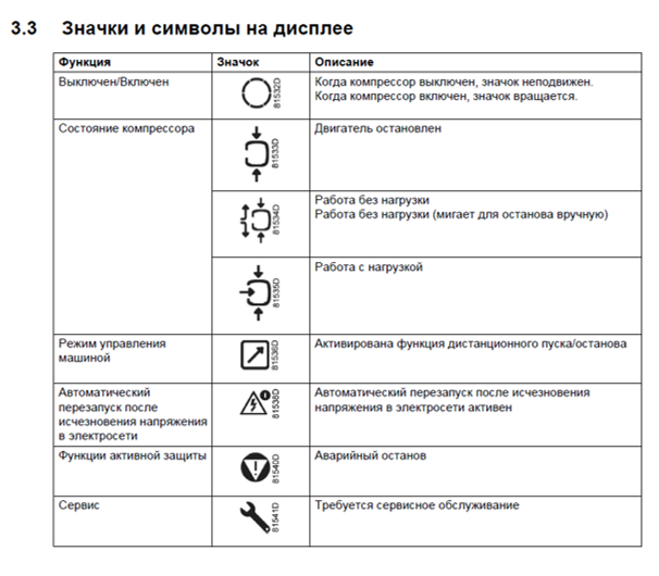
Icons used …………………………………………………………………………………………………………………………………………………….. 7
5.1
Status icons …………………………………………………………………………………………………………………………………………….. 7
6
Main screen ………………………………………………………………………………………………………………………………………………….. 9
7
Shut-down warning ………………………………………………………………………………………………………………………………………. 10
7.1
Description …………………………………………………………………………………………………………………………………………….. 10
7.2
Compressor element outlet temperature …………………………………………………………………………………………………….. 10
7.3
Dewpoint temperature ……………………………………………………………………………………………………………………………… 11
8
Shut-down …………………………………………………………………………………………………………………………………………………… 12
8.1
Description …………………………………………………………………………………………………………………………………………….. 12
8.2
Compressor element outlet temperature …………………………………………………………………………………………………….. 12
8.3
Motor overload ……………………………………………………………………………………………………………………………………….. 13
9
Service warning …………………………………………………………………………………………………………………………………………… 14
02/04/2013
PM 2946 7002 09
ES 4000 STANDARD
:
2946 7002 09
:
MB compressors
:
—
:
General
:
1
:
—
:
—
Page 1 of 39
58 480,00 ₽ В корзину
Заказать в 1 клик
Код производителя: 2996710200
Производитель: Ekomak, Турция
Блок управления (панель электронная) Ekomak ES 4000 Standard для винтового компрессора. Контроллер применяется на компрессорах турецкого производства Ekomak нового поколения, модели DMD400 и выше (больше 30кВт).
Все контроллеры серии ES4000 оснащаются портом RJ-45 для подключения по витой паре к удаленному компьютеру. С помощью удобного веб интерфейса осуществляется полный контроль над показателями винтового компрессора.
Вес: 0.1 кг

Изображения на сайте могут отличаться от фактического вида товара текущей партии.
Table of Contents for Chicago Pneumatic ES 4000 STANDARD:
-
02/04/2013 PM 2946 7002 09 Page 38 of 39 34 Programmable settings 34.1 Parameters: unloading/loading pressures Minimum setting Factory setting Maximum setting Unloading/loading pressures see Compressor data see Compressor data see Compressor data 34.2 Parameters fix speed drive Minimum setting Factory setting Maximum setting Motor running time in star sec 5 10 10 Load delay time (star-delta) sec 0 0 10 Number of motor starts starts/day 0 240 480 Minimum stop time sec
-
02/04/2013 PM 2946 7002 09 Page 3 of 39 32.2 Example of protection screens………………………………………………………………………………………………………………. 36 32.3 Changing the settings ………………………………………………………………………………………………………………………….. 36 33 Test screens……………………………………………………………………………………………………………………………..
-
02/04/2013 PM 2946 7002 09 Page 7 of 39 5 Icons used 5.1 Status icons Name Icon Description Compressor status When the compressor is stopped, the icon stands still. When the compressor is running, the icon is rotating. Motor stopped Running unloaded Running loaded Machine control mode Remote start / stop LAN control Automatic restart after voltage failure Automatic restart after voltage failure is a
-
02/04/2013 PM 2946 7002 09 Page 20 of 39 12 Calling up running hours Starting from the Main screen: 1. Press Scroll button (12) until <d.1> is shown. 2. Press Enter button (13). The screen shows the unit used (x1000 hrs) and the value (11.25): the running hours of the compressor are 11250 hours. 13 Calling up motor starts Starting from the Main screen: 1. Press Scroll button (12) until <d.2> is shown. 2. Press Enter button (13). A screen similar to the following appears This screen shows the number of motor start
-
02/04/2013 PM 2946 7002 09 Page 13 of 39 8.3 Motor overload In the event of motor overload, the compressor will be shut-down, alarm LED (5) will flash, automatic operation LED (3) will go out and the following screen will appear. Main screen with shut-down indication, motor overload 1. Switch off the voltage. 2. Remedy the trouble. 3. After remedying and when the shut-down condition has disappeared, switch on the voltage. 4. Restart the compressor. 1
-
02/04/2013 PM 2946 7002 09 Page 25 of 39 19 Calling up/modifying CAN address control 19.1 Calling up Starting from the Main screen: 1. Press Scroll button (12) until <P.02> is shown. 2. Press Enter button (13). 3. If necessary enter the password. The next screen shows that the function is ON or OFF. 4. Press the Enter button (13) to change this mode. 5. Use the Scroll buttons (12) to select &l
-
02/04/2013 PM 2946 7002 09 Page 14 of 39 9 Service warning 9.1 Description A service warning will appear when the service timer has reached the programmed time interval. If the service timer exceeds the programmed time interval, alarm LED (5) will light up. 1. Press Scroll buttons (12) to scroll to <d.6>. The service symbol is shown. 2. Press button (13). The actual reading of the service timer appears and is shown in <hrs> or <x1000 hrs> (if the service timer value is higher than 9999). Example of servic
-
02/04/2013 PM 2946 7002 09 Page 4 of 39 3 General description View of the ES 4000 Standard controller 3.1 Introduction The electronic controller has following functions: • Controlling the compressor • Protecting the compressor • Monitoring components subject to service • Automatic restart after voltage failure 3.2 Automatic control of the compressor The controller maintains the net pressure between programmable limits by automatically loading and unloading th
-
02/04/2013 PM 2946 7002 09 Page 32 of 39 26 Activating automatic restart after voltage failure This function allows the compressor to restart automatically after a power failure. This parameter, accessible in screen <P.09>, can only be modified after entering a code. Consult your supplier if this function is to be activated. 27 Selection between Y-D or DOL starting Starting from the Main screen: 1. Press Scroll button (12) until <P.10> and the motor pictograph is shown. 2. Press En
-
02/04/2013 PM 2946 7002 09 Page 15 of 39 10 Scrolling through all screens 10.1 Description Scroll buttons (12) can be used to scroll through all screens. The screens are divided into register screens, measured data screens, digital input screens (numbered as <d.in>, <d.1>, …), parameter screens (numbered as <P.01>, <P.02>, …), protections screens (numbered as <Pr.01>,…) and test screens
-
02/04/2013 PM 2946 7002 09 Page 18 of 39 (1) Compressor outlet pressure (16) Pressure band setting (2) Compressor outlet temperature (17) Service timer settings (3) Dewpoint temperature (18) Temperature unit (4) Digital input status (19) Unit pressure (5) Running hours (20) Auto restart (6) Motor starts (21) Selection Y-D/DOL (7) Module hours (22) Load delay time (8) Loading hours (23) Minimum sto
Questions, Opinions and Exploitation Impressions:
You can ask a question, express your opinion or share our experience of Chicago Pneumatic ES 4000 STANDARD device using right now.
|
[Page 1] Chicago Pneumatic ES 4000 STANDARD 02/04/2013 PM 2946 7002 09 Page 1 of 39 Controller Instruction 1 General information ES 4000 STANDARD Printed Matter Number : 2946 7002 09 Applicable to : MB compressors Preliminary Operations: : – Safety Instructions : Gener… |
|
[Page 2] Chicago Pneumatic ES 4000 STANDARD 02/04/2013 PM 2946 7002 09 Page 2 of 39 9.1 Description …………………………………………………………………………………………………………………………………………….. 14 10 Scrolling through … |
|
[Page 3] Chicago Pneumatic ES 4000 STANDARD 02/04/2013 PM 2946 7002 09 Page 3 of 39 32.2 Example of protection screens………………………………………………………………………………………………………………. 36 32.3 Changing the settings …………. |
|
[Page 4] Chicago Pneumatic ES 4000 STANDARD 02/04/2013 PM 2946 7002 09 Page 4 of 39 3 General description View of the ES 4000 Standard controller 3.1 Introduction The electronic controller has following functions: • Controlling the compressor • Protecting the compressor �… |
|
[Page 5] Chicago Pneumatic ES 4000 STANDARD 02/04/2013 PM 2946 7002 09 Page 5 of 39 3.3.2 Shut-down warning A shut-down warning level is a programmable level below the shut-down level. If one of the measurements exceeds the programmed shut-down warning level, this will also be indicate… |
|
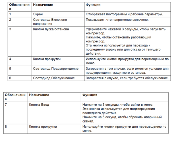
[Page 6] Chicago Pneumatic ES 4000 STANDARD 02/04/2013 PM 2946 7002 09 Page 6 of 39 4 Detailed description of the control panel Function keys of the controller Ref. Designation Function 1 Display Shows icons and operating conditions. 2 Automatic operation symbol 3 LE… |
|
[Page 7] Chicago Pneumatic ES 4000 STANDARD 02/04/2013 PM 2946 7002 09 Page 7 of 39 5 Icons used 5.1 Status icons Name Icon Description Compressor status When the compressor is stopped, the icon stands still. When the compressor is running, the icon is rotating. Motor stopp… |
|
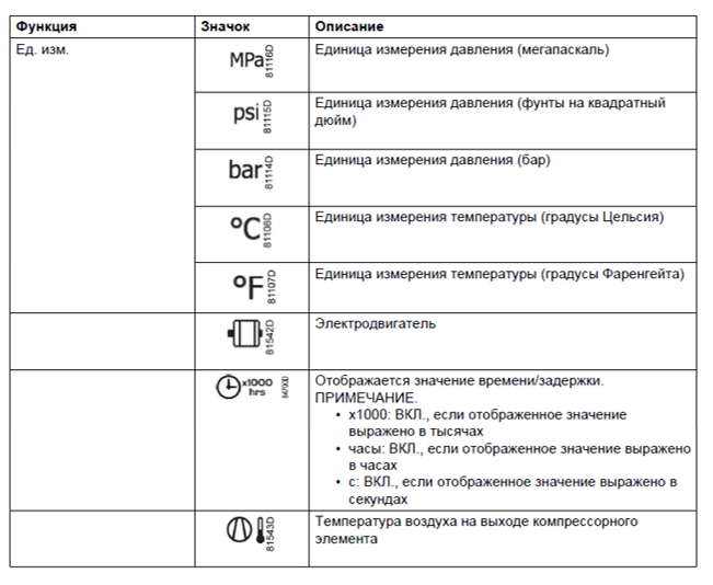
[Page 8] Chicago Pneumatic ES 4000 STANDARD 02/04/2013 PM 2946 7002 09 Page 8 of 39 Name Icon Description Temperature unit Hours (always shown together with seconds) Percent The value shown must be multiplied by 10 to get the actual value The value shown must be multipl… |
|
[Page 9] Chicago Pneumatic ES 4000 STANDARD 02/04/2013 PM 2946 7002 09 Page 9 of 39 6 Main screen When the voltage is switched on, the first screen is a test screen. The next screen is the Main screen, shown automatically. The Main screen shows: • The compressor status by means… |
|
[Page 10] Chicago Pneumatic ES 4000 STANDARD 02/04/2013 PM 2946 7002 09 Page 10 of 39 7 Shut-down warning 7.1 Description A shut-down warning will appear in the event of: • Too high a temperature at the outlet of the compressor element. • Too high a dewpoint temperature (Full-F… |
|
[Page 11] Chicago Pneumatic ES 4000 STANDARD 02/04/2013 PM 2946 7002 09 Page 11 of 39 7.3 Dewpoint temperature On compressors with integrated dryer, alarm LED (5) will light up and the related pictograph will appear flashing if the dewpoint temperature exceeds the warning level (program… |
|
[Page 12] Chicago Pneumatic ES 4000 STANDARD 02/04/2013 PM 2946 7002 09 Page 12 of 39 8 Shut-down 8.1 Description The compressor will be shut down: • In case the temperature at the outlet of the compressor element exceeds the shut-down level. • In case of error of the outlet pr… |
|
[Page 13] Chicago Pneumatic ES 4000 STANDARD 02/04/2013 PM 2946 7002 09 Page 13 of 39 8.3 Motor overload In the event of motor overload, the compressor will be shut-down, alarm LED (5) will flash, automatic operation LED (3) will go out and the following screen will appear. Main scre… |
|
[Page 14] Chicago Pneumatic ES 4000 STANDARD 02/04/2013 PM 2946 7002 09 Page 14 of 39 9 Service warning 9.1 Description A service warning will appear when the service timer has reached the programmed time interval. If the service timer exceeds the programmed time interval, alarm LED (… |
|
[Page 15] Chicago Pneumatic ES 4000 STANDARD 02/04/2013 PM 2946 7002 09 Page 15 of 39 10 Scrolling through all screens 10.1 Description Scroll buttons (12) can be used to scroll through all screens. The screens are divided into register screens, measured data screens, digital input sc… |
|
[Page 16] Chicago Pneumatic ES 4000 STANDARD 02/04/2013 PM 2946 7002 09 Page 16 of 39 Parameter screens Designation Related topic <P.04> Pressure band settings See section Calling up/modifying pressure band settings <P.05> Setting a pressure band selection See section M… |
|
[Page 17] Chicago Pneumatic ES 4000 STANDARD 02/04/2013 PM 2946 7002 09 Page 17 of 39 10.3 Menu flow Simplified menu flow 1 |
|
[Page 18] Chicago Pneumatic ES 4000 STANDARD 02/04/2013 PM 2946 7002 09 Page 18 of 39 (1) Compressor outlet pressure (16) Pressure band setting (2) Compressor outlet temperature (17) Service timer settings (3) Dewpoint temperature (18) Temperature unit (4) Digital input stat… |
|
[Page 19] Chicago Pneumatic ES 4000 STANDARD 02/04/2013 PM 2946 7002 09 Page 19 of 39 11 Calling up outlet and dewpoint temperatures Starting from the Main screen: 1. Press Scroll button (12). The outlet temperature will be shown. The screen shows that the outlet temperature i… |
|
[Page 20] Chicago Pneumatic ES 4000 STANDARD 02/04/2013 PM 2946 7002 09 Page 20 of 39 12 Calling up running hours Starting from the Main screen: 1. Press Scroll button (12) until <d.1> is shown. 2. Press Enter button (13). The screen shows the unit used (x1000 hrs) and the… |
|
[Page 21] Chicago Pneumatic ES 4000 STANDARD 02/04/2013 PM 2946 7002 09 Page 21 of 39 14 Calling up module hours Starting from the Main screen: 1. Press Scroll button (12) until <d.3> is shown. 2. Press Enter button (13). A screen similar to the following appears The scre… |
|
[Page 22] Chicago Pneumatic ES 4000 STANDARD 02/04/2013 PM 2946 7002 09 Page 22 of 39 16 Calling up load relay Starting from the Main screen: 1. Press Scroll button (12) until <d.5> is shown. 2. Press Enter button (13). This screen shows the number of unload to load acti… |
|
[Page 23] Chicago Pneumatic ES 4000 STANDARD 02/04/2013 PM 2946 7002 09 Page 23 of 39 17 Calling up/resetting the service timer 17.1 Calling up the service timer Starting from the Main screen: 1. Press Scroll button (12) until <d.6> is shown. 2. Press Enter button (13). … |
|
[Page 24] Chicago Pneumatic ES 4000 STANDARD 02/04/2013 PM 2946 7002 09 Page 24 of 39 18 Selection between local, remote or LAN control Starting from the Main screen: 1. Press Scroll button (12) until <P.01> is shown. 2. Press Enter button (13). The actually selected control… |
|
[Page 25] Chicago Pneumatic ES 4000 STANDARD 02/04/2013 PM 2946 7002 09 Page 25 of 39 19 Calling up/modifying CAN address control 19.1 Calling up Starting from the Main screen: 1. Press Scroll button (12) until <P.02> is shown. 2. Press Enter button (13). 3. If necessary en… |
|
[Page 26] Chicago Pneumatic ES 4000 STANDARD 02/04/2013 PM 2946 7002 09 Page 26 of 39 19.2 Modifying the Node ID The Node ID can be changed; use a value between 1 and 31. When the function is ON, the parameters cannot be modified. Change the function to OFF to change the node ID. … |
|
[Page 27] Chicago Pneumatic ES 4000 STANDARD 02/04/2013 PM 2946 7002 09 Page 27 of 39 20 Calling up/modifying IP, Gateway and Subnetmask 20.1 Calling up Starting from the Main screen: 1. Press Scroll button (12) until <P.03> is shown. 2. Press Enter button (13). The next scr… |
|
[Page 28] Chicago Pneumatic ES 4000 STANDARD 02/04/2013 PM 2946 7002 09 Page 28 of 39 20.2 Modification 1. Press the Enter button (13). 2. If necessary enter the password. The first digits are blinking. 3. Use the Scroll buttons Up or Down (12) to modify the settings. 4. Press … |
|
[Page 29] Chicago Pneumatic ES 4000 STANDARD 02/04/2013 PM 2946 7002 09 Page 29 of 39 21 Calling up/modifying pressure band settings 21.1 Calling up the settings Starting from the Main screen: 1. Press Scroll button (12) until <P.04> is shown. 2. Press Enter button (13). … |
|
[Page 30] Chicago Pneumatic ES 4000 STANDARD 02/04/2013 PM 2946 7002 09 Page 30 of 39 21.2 Modification 1. Press Enter button (13) to modify the load level (value starts blinking). A password may be required. 2. Use Scroll buttons (12) to change the loading pressure. 3. Press Ent… |
|
[Page 31] Chicago Pneumatic ES 4000 STANDARD 02/04/2013 PM 2946 7002 09 Page 31 of 39 24 Calling up/modifying the unit of temperature Starting from the Main screen: 1. Press Scroll button (12) until <P.07> is shown. 2. Press Enter button (13). The actually used unit is shown… |
|
[Page 32] Chicago Pneumatic ES 4000 STANDARD 02/04/2013 PM 2946 7002 09 Page 32 of 39 26 Activating automatic restart after voltage failure This function allows the compressor to restart automatically after a power failure. This parameter, accessible in screen <P.09>, can only b… |
|
[Page 33] Chicago Pneumatic ES 4000 STANDARD 02/04/2013 PM 2946 7002 09 Page 33 of 39 28 Calling up modifying load delay time Starting from the Main screen: 1. Press Scroll button (12) until <P.11> and the compressor load pictograph is shown. 2. Press Enter button (13). Th… |
|
[Page 34] Chicago Pneumatic ES 4000 STANDARD 02/04/2013 PM 2946 7002 09 Page 34 of 39 30 Activating password protection Important settings such as the setting of the service timer, pressure band setting, control mode settings,… can be protected by a password. Starting from the Main… |
|
[Page 35] Chicago Pneumatic ES 4000 STANDARD 02/04/2013 PM 2946 7002 09 Page 35 of 39 31 Activate load/unload remote pressure sensing Starting from the Main screen: 1. Press Scroll button (12) until <P.14> is shown. 2. Press Enter button (13). The function of this screen i… |
|
[Page 36] Chicago Pneumatic ES 4000 STANDARD 02/04/2013 PM 2946 7002 09 Page 36 of 39 32.2 Example of protection screens Protection setting element outlet temperature Warning alarm high element outlet temperature 32.3 Changing the settings Starting from the Main screen (the e… |
|
[Page 37] Chicago Pneumatic ES 4000 STANDARD 02/04/2013 PM 2946 7002 09 Page 37 of 39 33 Test screens 33.1 Display test Starting from the Main screen. 1. Press Scroll buttons (12) until <t.01> is shown. 2. Press Enter button (13). The display now shows all icons that can be… |
|
[Page 38] Chicago Pneumatic ES 4000 STANDARD 02/04/2013 PM 2946 7002 09 Page 38 of 39 34 Programmable settings 34.1 Parameters: unloading/loading pressures Minimum setting Factory setting Maximum setting Unloading/loading pressures see Compressor data see Compressor data see Co… |
|
[Page 39] Chicago Pneumatic ES 4000 STANDARD 02/04/2013 PM 2946 7002 09 Page 39 of 39 34.5 Terminology Term Explanation ARAVF Activating automatic restart after voltage failure. Power recovery time Is the period within which the voltage must be restored to have an automatic restart…. |
Controller Instruction
1
General information
ES 4000 STANDARD
Printed Matter Number
:
2946 7002 09
Applicable to
:
MB compressors
Preliminary Operations:
:
–
Safety Instructions
:
General
Persons Required
:
1
Special Tools
:
–
Consumables
:
–
2
Document Overview
This document describes the following:
1
General information............................................................................................................................................................ 1
2
Document Overview ........................................................................................................................................................... 1
3
General description ............................................................................................................................................................ 4
3.1
Introduction .................................................................................................................................................................. 4
3.2
Automatic control of the compressor ............................................................................................................................ 4
3.3
Protecting the compressor ........................................................................................................................................... 4
3.3.1
Shut-down ........................................................................................................................................................... 4
3.3.2
Shut-down warning .............................................................................................................................................. 5
3.4
Service warning............................................................................................................................................................ 5
3.5
Automatic restart after voltage failure........................................................................................................................... 5
4
Detailed description of the control panel ............................................................................................................................ 6
5
Icons used.......................................................................................................................................................................... 7
5.1
Status icons ................................................................................................................................................................. 7
6
Main screen ....................................................................................................................................................................... 9
7
Shut-down warning .......................................................................................................................................................... 10
8
9
7.1
Description ................................................................................................................................................................. 10
7.2
Compressor element outlet temperature .................................................................................................................... 10
7.3
Dewpoint temperature ................................................................................................................................................ 11
Shut-down ........................................................................................................................................................................ 12
8.1
Description ................................................................................................................................................................. 12
8.2
Compressor element outlet temperature .................................................................................................................... 12
8.3
Motor overload ........................................................................................................................................................... 13
Service warning ............................................................................................................................................................... 14
02/04/2013
PM 2946 7002 09
Page 1 of 39
1
9.1
10
Description ................................................................................................................................................................. 14
Scrolling through all screens ...................................................................................................................................... 15
10.1
Description ............................................................................................................................................................. 15
10.2
Overview of the screens ........................................................................................................................................ 15
10.2.1
Overview of the Digital input screens ................................................................................................................ 15
10.2.2
Overview of the Parameter screens .................................................................................................................. 15
10.2.3
Overview of the Protections screens ................................................................................................................. 16
10.2.4
Overview of the Test screens ............................................................................................................................ 16
10.3
Menu flow .............................................................................................................................................................. 17
11
Calling up outlet and dewpoint temperatures ............................................................................................................. 19
12
Calling up running hours ............................................................................................................................................ 20
13
Calling up motor starts ............................................................................................................................................... 20
14
Calling up module hours ............................................................................................................................................ 21
15
Calling up loading hours............................................................................................................................................. 21
16
Calling up load relay................................................................................................................................................... 22
17
Calling up/resetting the service timer ......................................................................................................................... 23
17.1
Calling up the service timer ................................................................................................................................... 23
17.2
Resetting the service timer .................................................................................................................................... 23
18
Selection between local, remote or LAN control......................................................................................................... 24
19
Calling up/modifying CAN address control ................................................................................................................. 25
19.1
Calling up............................................................................................................................................................... 25
19.2
Modifying the Node ID ........................................................................................................................................... 26
20
Calling up/modifying IP, Gateway and Subnetmask................................................................................................... 27
20.1
Calling up............................................................................................................................................................... 27
20.2
Modification............................................................................................................................................................ 28
21
Calling up/modifying pressure band settings.............................................................................................................. 29
21.1
Calling up the settings ........................................................................................................................................... 29
21.2
Modification............................................................................................................................................................ 30
22
Modifying the pressure band selection ....................................................................................................................... 30
23
Calling up/modifying service timer settings ................................................................................................................ 30
24
Calling up/modifying the unit of temperature .............................................................................................................. 31
25
Calling up/modifying unit of pressure ......................................................................................................................... 31
26
Activating automatic restart after voltage failure ........................................................................................................ 32
27
Selection between Y-D or DOL starting ..................................................................................................................... 32
28
Calling up modifying load delay time .......................................................................................................................... 33
29
Calling up modifying minimum stop time .................................................................................................................... 33
30
Activating password protection................................................................................................................................... 34
31
Activate load/unload remote pressure sensing........................................................................................................... 35
32
Calling up/modifying protection settings ..................................................................................................................... 35
32.1
Available protections.............................................................................................................................................. 35
02/04/2013
PM 2946 7002 09
Page 2 of 39
1
32.2
Example of protection screens............................................................................................................................... 36
32.3
Changing the settings ............................................................................................................................................ 36
33
Test screens............................................................................................................................................................... 37
33.1
Display test ............................................................................................................................................................ 37
33.2
Safety valve test .................................................................................................................................................... 37
33.3
Production test ....................................................................................................................................................... 37
34
Programmable settings .............................................................................................................................................. 38
34.1
Parameters: unloading/loading pressures ............................................................................................................. 38
34.2
Parameters fix speed drive .................................................................................................................................... 38
34.3
Protections ............................................................................................................................................................. 38
34.4
Service plan ........................................................................................................................................................... 38
34.5
Terminology ........................................................................................................................................................... 39
02/04/2013
PM 2946 7002 09
Page 3 of 39
1
3
General description
View of the ES 4000 Standard controller
3.1
Introduction
The electronic controller has following functions:
•
Controlling the compressor
•
Protecting the compressor
•
Monitoring components subject to service
•
Automatic restart after voltage failure
3.2
Automatic control of the compressor
The controller maintains the net pressure between programmable limits by automatically loading and unloading the
compressor. A number of programmable settings, e.g. the unloading and loading pressures, the minimum stop time and the
maximum number of motor starts are taken into account.
The controller stops the compressor whenever possible to reduce the power consumption and restarts it automatically when
the net pressure decreases. If the expected unloading period is to short, the compressor is kept running to prevent too short
stand-still periods.
3.3
3.3.1
Protecting the compressor
Shut-down
If the compressor element outlet temperature exceeds the programmed shut-down level, the compressor will be stopped.
This will be indicated on the display of the controller. The compressor will also be stopped in case of overload of the drive
motor.
Air-cooled compressors will also be stopped in the event of overload of the fan motor.
Before remedying, consult the Safety precautions in the Instruction book.
02/04/2013
PM 2946 7002 09
Page 4 of 39
1
3.3.2
Shut-down warning
A shut-down warning level is a programmable level below the shut-down level.
If one of the measurements exceeds the programmed shut-down warning level, this will also be indicated to warn the
operator before the shut-down level is reached.
3.4
Service warning
If the service timer exceeds a programmed value, this will be indicated on the display to warn the operator to carry out some
service actions.
3.5
Automatic restart after voltage failure
The controller has a built-in function to automatically restart the compressor when the voltage is restored after voltage
failure.
Provided the controller is in the automatic operation mode, the compressor will automatically restart when
the supply voltage to the module is restored.
02/04/2013
PM 2946 7002 09
Page 5 of 39
1
4
Detailed description of the control panel
Function keys of the controller
Ref.
Designation
Function
1
Display
Shows icons and operating conditions.
2
Automatic operation symbol
3
LED, Automatic operation
4
Warning symbol
5
LED, Warning
6
Voltage symbol
7
LED, Voltage on
8
Service symbol
9
LED, Service
Is lit when service is needed.
10
Start button
This button starts the compressor. Automatic operation LED (3) lights up. The
Elektronikon is operative.
11
Stop button
This button is used to stop the compressor. Automatic operation LED (3) goes out.
12
Scroll buttons
Use these buttons to scroll through the menu.
13
Enter button
Use this button to confirm the last action.
14
Escape button
Use this button to go to previous screen or to end the current action.
02/04/2013
PM 2946 7002 09
Indicates that the regulator is automatically controlling the compressor: the compressor
is loaded, unloaded, stopped and restarted depending on the air consumption and the
limitations programmed in the regulator.
Is lit if a warning condition exists.
Indicates that the voltage is switched on.
Page 6 of 39
1
5
Icons used
5.1
Status icons
Name
Compressor status
Icon
Description
When the compressor is stopped, the icon stands still.
When the compressor is running, the icon is rotating.
Motor stopped
Running unloaded
Running loaded
Machine control mode
Remote start / stop
LAN control
Automatic restart after
voltage failure
Automatic restart after voltage failure is active
Timer
Active protection
functions
Emergency stop
Service
Service required
Units
Pressure unit (Mega Pascal)
Pressure unit (pounds per square inch)
Pressure unit (bar)
Temperature unit
02/04/2013
PM 2946 7002 09
Page 7 of 39
1
Name
Icon
Description
Temperature unit
Hours (always shown together with seconds)
Percent
The value shown must be multiplied by 10 to get the actual value
The value shown must be multiplied by 100 to get the actual value
The value shown must be multiplied by 1000 to get the actual value
Motor (overload)
Element outlet temperature
Filter
Drain
Energy saving (dryer)
Ambient temperature
Dewpoint temperature
02/04/2013
PM 2946 7002 09
Page 8 of 39
1
6
Main screen
When the voltage is switched on, the first screen is a test screen. The next screen is the Main screen, shown automatically.
The Main screen shows:
•
The compressor status by means of pictographs
•
The air outlet pressure
Always consult your supplier if the pressure on the display is preceded by a "t".
02/04/2013
PM 2946 7002 09
Page 9 of 39
1
7
7.1
Shut-down warning
Description
A shut-down warning will appear in the event of:
•
Too high a temperature at the outlet of the compressor element.
•
Too high a dewpoint temperature (Full-Feature compressors).
7.2
Compressor element outlet temperature
If the outlet temperature of the compressor element exceeds the shut-down warning level (see section Programmable
settings), warning LED (5) starts blinking.
1.
Press the Scroll down button.
The screen shows the temperature at the compressor element outlet.
The screen shows that the temperature at the element outlet is 122 °C
It remains possible to scroll through other screens, using the Scroll buttons up and down (12) to check the actual status
of other parameters.
2.
Press button (11) to stop the compressor and wait until the compressor has stopped.
3.
Switch off the voltage, inspect the compressor and remedy.
The warning message will disappear as soon if the warning condition disappears.
02/04/2013
PM 2946 7002 09
Page 10 of 39
1
7.3
Dewpoint temperature
On compressors with integrated dryer, alarm LED (5) will light up and the related pictograph will appear flashing if the
dewpoint temperature exceeds the warning level (programmable).
Main screen with the dewpoint temperature warning
The related pictograph will appear flashing:
1.
Press the Scroll button (12) until the actual dewpoint temperature appears.
Warning screen, dewpoint temperature
The screen shows that the dewpoint temperature is 9 ˚C.
It remains possible to scroll through other screens (using Scroll buttons 12) to check the actual status of other
parameters.
2.
Press button (11) to stop the compressor.
Wait until the compressor has stopped.
3.
Switch off the voltage, inspect the compressor and remedy.
The warning message will disappear as soon as the warning condition disappears.
02/04/2013
PM 2946 7002 09
Page 11 of 39
1
8
8.1
Shut-down
Description
The compressor will be shut down:
•
In case the temperature at the outlet of the compressor element exceeds the shut-down level.
•
In case of error of the outlet pressure sensor.
•
In case of overload of the drive motor.
•
In case of overload of the fan motor on air-cooled compressors.
8.2
Compressor element outlet temperature
If the outlet temperature of the compressor element exceeds the shut-down level (factory setting 120 °C/248 °F,
programmable) the compressor will be shut-down, alarm LED (5) will flash, automatic operation LED (3) will go out and the
following screen will appear.
Main screen with shut-down indication, element outlet temperature
The related pictograph will appear flashing:
1.
Press the Scroll button (12) until the actual compressor element temperature appears.
Shut-down screen, element outlet temperature
The screen shows that the temperature at the outlet of the compressor element is 122 °C.
2.
Switch off the voltage.
3.
Remedy the trouble.
4.
After remedying and when the shut-down condition has disappeared, switch on the voltage.
5.
Restart the compressor.
02/04/2013
PM 2946 7002 09
Page 12 of 39
1
8.3
Motor overload
In the event of motor overload, the compressor will be shut-down, alarm LED (5) will flash, automatic operation LED (3) will
go out and the following screen will appear.
Main screen with shut-down indication, motor overload
1.
Switch off the voltage.
2.
Remedy the trouble.
3.
After remedying and when the shut-down condition has disappeared, switch on the voltage.
4.
Restart the compressor.
02/04/2013
PM 2946 7002 09
Page 13 of 39
1
9
9.1
Service warning
Description
A service warning will appear when the service timer has reached the programmed time interval.
If the service timer exceeds the programmed time interval, alarm LED (5) will light up.
1.
Press Scroll buttons (12) to scroll to <d.6>.
The service symbol is shown.
2.
Press button (13).
The actual reading of the service timer appears and is shown in <hrs> or <x1000 hrs> (if the service timer value is
higher than 9999).
Example of service timer screen
The screen shows that the reading of the service timer is 4002.
3.
Press Scroll button (12) to scroll to <d.1>.
The running hours symbol is shown.
4.
Press button (13).
The actual reading of the service timer appears and is shown in <hrs> or <x1000 hrs> (if the service timer value is
higher than 9999).
Example of running hours screen
The longer interval service actions must also include the shorter interval actions. In the example above,
carry out all service operations belonging to the 8000 running hours interval as well as those belonging to
the 4000 running hours interval.
The setting of the service timer can be changed in function of the operating conditions See section
Preventive maintenance schedule.
5.
After servicing, reset the service timer. See section Calling up/resetting the service timer.
02/04/2013
PM 2946 7002 09
Page 14 of 39
1
10 Scrolling through all screens
10.1 Description
Scroll buttons (12) can be used to scroll through all screens. The screens are divided into register screens, measured data
screens, digital input screens (numbered as <d.in>, <d.1>, ...), parameter screens (numbered as <P.01>, <P.02>, ...),
protections screens (numbered as <Pr.01>,...) and test screens (numbered as <t.01>,...).
During scrolling, the numbers of the screens appear consecutively. For most screens, the unit of measurement and the
related pictograph are shown together with the screen number.
Example
The screen shows the screen number <d.1>, the unit used <hrs> and the related symbol for running hours.
Press Enter key (13) to call up the actual running hours.
10.2 Overview of the screens
10.2.1 Overview of the Digital input screens
Digital input screens
Designation
Related topic
<d.in>
Digital input status
<d.1>
Running hours (hrs or x 1000 hrs)
See section Calling up running hours
<d.2>
Motor starts (x 1 or x 1000)
See section Calling up motor starts
<d.3>
Module hours (hrs or x 1000 hrs)
See section Calling up module hours
<d.4>
Loading hours (hrs or x1000 hrs)
See section Calling up loading hours
<d.5>
Load relay (x1 or x 1000)
See section Calling up load relay
<d.6>
Service timer reading (hrs or x 1000 hrs)
See section Calling up/resetting the service timer
<d.7>
Actual program version
10.2.2 Overview of the Parameter screens
Parameter screens
Designation
Related topic
<P.01>
Selection between local, remote or LAN
control
See section Selection between local, remote or LAN control
<P.02>
Setting a node ID for LAN control and the
channels for Mk 4 and Mk 5
See section Calling up/modifying CAN address control
<P.03>
Settings for IP, gateway and Subnet mask
See section Calling up/modifying IP, Gateway and
Subnetmask
02/04/2013
PM 2946 7002 09
Page 15 of 39
1
Parameter screens
Designation
Related topic
<P.04>
Pressure band settings
See section Calling up/modifying pressure band settings
<P.05>
Setting a pressure band selection
See section Modifying the pressure band selection
<P.06>
Modifying a service timer
See section Calling up/modifying service timer settings
<P.07>
Setting of unit for temperature
See section Calling up/modifying the unit of temperature
<P.08>
Setting of unit for pressure
See section Calling up/modifying unit of pressure
<P.09>
Selection for function: Automatic restart after
voltage failure
See section Activating automatic restart after voltage failure
<P.10>
Selection between Y-D or DOL starting
See section Selection between Y-D or DOL starting
<P.11>
Setting of load delay time
See section Calling up modifying load delay time
<P.12>
Setting of minimum stop time
See section Calling up modifying minimum stop time
<P.13>
Setting a password
See section Activating password protection
<P.14>
Remote pressure sensing
See section Activate load/unload remote pressure sensing
10.2.3 Overview of the Protections screens
Protections screens
Designation
Related topic
<Pr.01>
Protections screens
See section Calling up/modifying protection settings
<Pr.02>
<Pr.03>
10.2.4 Overview of the Test screens
Test screens
Designation
Related topic
<t.01>
Display test
See section Test screens
<t.02>
Safe valve test
See section Test screens
<t.03>
Production test
See section Test screens
02/04/2013
PM 2946 7002 09
Page 16 of 39
1
10.3 Menu flow
Simplified menu flow
02/04/2013
PM 2946 7002 09
Page 17 of 39
1
(1)
Compressor outlet pressure
(16)
Pressure band setting
(2)
Compressor outlet temperature
(17)
Service timer settings
(3)
Dewpoint temperature
(18)
Temperature unit
(4)
Digital input status
(19)
Unit pressure
(5)
Running hours
(20)
Auto restart
(6)
Motor starts
(21)
Selection Y-D/DOL
(7)
Module hours
(22)
Load delay time
(8)
Loading hours
(23)
Minimum stop time
(9)
Load relay
(24)
Password settings
(10)
Service timer reading
(25)
Remote pressure sensing
(11)
Actual program version
(26)
Protections
(12)
LAN selection
(27)
Display test
(13)
Settings node ID
(28)
Safety valve test
(14)
IP settings
(29)
Production test
(15)
Pressure band selection
02/04/2013
PM 2946 7002 09
Page 18 of 39
1
11 Calling up outlet and dewpoint temperatures
Starting from the Main screen:
1.
Press Scroll button (12).
The outlet temperature will be shown.
The screen shows that the outlet temperature is 82 ˚C.
For Full-Feature compressors:
1.
Press Scroll button (12).
The dewpoint temperature will be shown:
The screen shows that the dewpoint temperature is 3 ˚C.
2.
Press Scroll button (12) to scroll downwards or upwards through the screens.
02/04/2013
PM 2946 7002 09
Page 19 of 39
1
12 Calling up running hours
Starting from the Main screen:
1.
Press Scroll button (12) until <d.1> is shown.
2.
Press Enter button (13).
The screen shows the unit used (x1000 hrs) and the value (11.25): the running hours of the compressor are 11250
hours.
13 Calling up motor starts
Starting from the Main screen:
1.
Press Scroll button (12) until <d.2> is shown.
2.
Press Enter button (13).
A screen similar to the following appears
This screen shows the number of motor starts (x 1 or - if <x1000> lights up - x 1000). In the above example, the
number of motor starts is 10100.
02/04/2013
PM 2946 7002 09
Page 20 of 39
1
14 Calling up module hours
Starting from the Main screen:
1.
Press Scroll button (12) until <d.3> is shown.
2.
Press Enter button (13).
A screen similar to the following appears
The screen shows the unit used (hrs) and the value (5000): the regulator module has been in service during 5000
hours.
15 Calling up loading hours
Starting from the Main screen:
1.
Press Scroll button (12) until <d.4> is shown.
2.
Press Enter button (13).
A screen similar to the following appears
The screen shows the unit used <hrs> (or <x1000 hrs>) and the value <1755>: the compressor has been running
loaded during 1755 hours.
02/04/2013
PM 2946 7002 09
Page 21 of 39
1
16 Calling up load relay
Starting from the Main screen:
1.
Press Scroll button (12) until <d.5> is shown.
2.
Press Enter button (13).
This screen shows the number of unload to load actions (x 1 or - if <x1000> lights up - x 1000). In the above example,
the number of unload to load actions is 10100.
02/04/2013
PM 2946 7002 09
Page 22 of 39
1
17 Calling up/resetting the service timer
17.1 Calling up the service timer
Starting from the Main screen:
1.
Press Scroll button (12) until <d.6> is shown.
2.
Press Enter button (13).
This screen shows the unit used <hrs> (or <x1000 hrs>) and the value <1191>. In the example shown, the compressor
has run 1191 hours since the previous service.
17.2 Resetting the service timer
After servicing, see section Service warning, the timer has to be reset:
1.
Scroll to register screen <d.6>.
2.
Press Enter button (13).
The reading (e.g. 4000) will appear.
3.
Press Enter button (13).
4.
If a password is set, enter the password.
The icon will flash (indicating that resetting is possible).
5.
Press Enter button (13) to reset the timer to <0.000> or press the Escape button (14) to cancel the operation.
02/04/2013
PM 2946 7002 09
Page 23 of 39
1
18 Selection between local, remote or LAN control
Starting from the Main screen:
1.
Press Scroll button (12) until <P.01> is shown.
2.
Press Enter button (13).
The actually selected control mode is shown:
•
<LOC> for local control
•
<rE> for remote control
•
<LAn> for LAN control
To change:
1.
Press Enter button (13)
2.
If necessary - enter the password (see section Activating password protection).
The actually selected control mode is blinking.
3.
Use Scroll button (12) to change the control mode.
4.
Press Enter button (13) to program the new control mode or press Escape button (14) to cancel.
02/04/2013
PM 2946 7002 09
Page 24 of 39
1
19 Calling up/modifying CAN address control
19.1 Calling up
Starting from the Main screen:
1.
Press Scroll button (12) until <P.02> is shown.
2.
Press Enter button (13).
3.
If necessary enter the password.
The next screen shows that the function is ON or OFF.
4.
Press the Enter button (13) to change this mode.
5.
Use the Scroll buttons (12) to select <ON> or <OFF>.
6.
Press Enter to program.
7.
When this function is ON, use the Scroll buttons up or down (12) to see the node ID.
8.
If desired the user can change this ID., by pressing the Enter button (13).
The node ID value starts blinking.
9.
Use the Scroll buttons (12) to change the node ID.
10. Press the Enter button (13) to program the new node ID or press the Escape button (14) to leave this screen or to
cancel this operation.
02/04/2013
PM 2946 7002 09
Page 25 of 39
1
19.2 Modifying the Node ID
The Node ID can be changed; use a value between 1 and 31. When the function is ON, the parameters cannot be modified.
Change the function to OFF to change the node ID.
It is also possible to change the channels. The controller has 4 channels. When changing the channels, the controller can
act as a Mk IV controller (a previous version of the controller). To set the channels, go to the screen where the node ID is
visible.
1.
Press the Scroll button down (12).
The following screen appears.
2.
Press the Enter button (13) to modify the setting.
The utmost left value will blink.
3.
Change this value by using the Scroll buttons (12).
4.
Press the Enter button (13) to confirm.
5.
Change the other values in the same way, as required.
After modifying the settings, the screen may look as follows:
02/04/2013
PM 2946 7002 09
Page 26 of 39
1
20 Calling up/modifying IP, Gateway and Subnetmask
20.1 Calling up
Starting from the Main screen:
1.
Press Scroll button (12) until <P.03> is shown.
2.
Press Enter button (13).
The next screen shows that the function is ON or OFF.
3.
If ON, press the Enter button (13) to modify it to OFF.
4.
Use the Scroll buttons Up or Down (12) to scroll between the items in this list:
•
<IP> for IP address
•
<Sub> for Subnetmask
•
<GAtE> for Gateway
02/04/2013
PM 2946 7002 09
Page 27 of 39
1
20.2 Modification
1.
Press the Enter button (13).
2.
If necessary enter the password.
The first digits are blinking.
3.
Use the Scroll buttons Up or Down (12) to modify the settings.
4.
Press Enter (13) to confirm.
5.
Modify the next digits the same way. The standard IP address is set as 192.168.100.100.
02/04/2013
PM 2946 7002 09
Page 28 of 39
1
21 Calling up/modifying pressure band settings
21.1 Calling up the settings
Starting from the Main screen:
1.
Press Scroll button (12) until <P.04> is shown.
2.
Press Enter button (13).
Pressure band 1 (<Pb.1>) is shown on the display.
Button (12) can be used to scroll to pressure band 2 (<Pb.2>).
3.
Press the Enter button (13) on the desired pressure band.
The load level of the selected pressure band appears.
Button (12) can be used to scroll to the unload level.
Loading pressure
Unloading pressure
02/04/2013
PM 2946 7002 09
Page 29 of 39
1
21.2 Modification
1.
Press Enter button (13) to modify the load level (value starts blinking).
A password may be required.
2.
Use Scroll buttons (12) to change the loading pressure.
3.
Press Enter button (13) to program the new values or press the Escape button (14) to cancel.
22 Modifying the pressure band selection
Starting from the Main screen:
1.
Press Scroll button (12) until <P.05> is shown.
2.
Press Enter button (13).
The active pressure band 1 (<Pb.1>) is shown on the display.
3.
Press Enter button (13) to modify the pressure band selection (a password may be required).
The active pressure band <Pb.1> starts blinking.
4.
Press Scroll button (12) to modify the active pressure band.
5.
Press Enter button (13) to confirm or the Escape button (14) to cancel.
23 Calling up/modifying service timer settings
Starting from the Main screen:
1.
Press Scroll button (12) until <P.06> is shown.
2.
Press Enter button (13): the setting of the service timer is shown in <hrs> (hours) or <x1000 hrs> (hours x 1000).
Example: <4000 hrs> means the timer is set at 4000 running hours.
3.
Press Enter button (13) to modify this value (a password may be required).
The value starts blinking.
4.
Use the Scroll buttons (12) to modify the setting.
5.
Press Enter button (13) to program the new value.
02/04/2013
PM 2946 7002 09
Page 30 of 39
1
24 Calling up/modifying the unit of temperature
Starting from the Main screen:
1.
Press Scroll button (12) until <P.07> is shown.
2.
Press Enter button (13).
The actually used unit is shown.
Possible settings are <˚C> and <˚F>.
3.
Press Enter button (13)
Unit starts blinking.
4.
Use the Scroll buttons (12) to select another unit of temperature.
5.
Press Enter button (13) to program the new unit or press Escape button (14) to return to the parameter screen without
changes.
25 Calling up/modifying unit of pressure
Starting from the Main screen:
1.
2.
Press Scroll button (12) until <P.08> and the possible settings are shown:
•
<Mpa>
•
<psi>
•
<bar>
Press Enter button (13).
The actually used unit is shown.
3.
Press Enter button (13)
Unit starts blinking.
4.
Use the Scroll buttons (12) to select another unit of pressure.
5.
Press Enter button (13) to program the new unit of pressure.
6.
Press Escape button (14) to return to the parameter screens.
02/04/2013
PM 2946 7002 09
Page 31 of 39
1
26 Activating automatic restart after voltage failure
This function allows the compressor to restart automatically after a power failure.
This parameter, accessible in screen <P.09>, can only be modified after entering a code. Consult your supplier if this
function is to be activated.
27 Selection between Y-D or DOL starting
Starting from the Main screen:
1.
Press Scroll button (12) until <P.10> and the motor pictograph is shown.
2.
Press Enter button (13).
The actually used starting mode is shown:
•
<Y-D> (star-delta)
•
<doL> (Direct-On Line)
This parameter can only be modified after entering a code. Consult your supplier if the parameter is to be changed.
02/04/2013
PM 2946 7002 09
Page 32 of 39
1
28 Calling up modifying load delay time
Starting from the Main screen:
1.
Press Scroll button (12) until <P.11> and the compressor load pictograph is shown.
2.
Press Enter button (13).
This screen shows the load delay time (10) and the unit <s> seconds.
3.
To modify this value press the Enter button (13) (a password may be required).
The value starts blinking.
4.
Use the Scroll buttons (12) to modify the value.
5.
Press the Enter button (13) to program the new value.
The minimum and maximum value depends on the parameters.
29 Calling up modifying minimum stop time
Starting from the Main screen:
1.
Press Scroll button (12) until <P.12> and the motor pictograph is shown.
2.
Press Enter button (13).
This screen shows the minimum stop time (20) and the unit <s> seconds.
3.
To modify this value press the Enter button (13).
The value starts blinking.
4.
Use the Scroll buttons (12) to modify the value.
5.
Press the Enter button (13) to program the new value.
The minimum and maximum value depends on the parameters.
02/04/2013
PM 2946 7002 09
Page 33 of 39
1
30 Activating password protection
Important settings such as the setting of the service timer, pressure band setting, control mode settings,... can be protected
by a password.
Starting from the Main screen:
1.
Press Scroll button (12) until <P.13> is shown.
2.
Press Enter button (13).
Password (<PASS>) appears on the screen.
3.
Press the Enter button (13).
The screen shows the password status:
ON (<On>)
•
OFF (<OFF>)
•
4.
Press Enter button (13) to modify.
5.
Change the value with Scroll buttons (12).
6.
Select <On>.
7.
Press Enter button (13).
8.
Enter the new password.
9.
Press Enter button (13) to confirm.
10. Enter the password again.
11. Press Enter button (13) to confirm.
<On> appears on the display.
12. Press Reset key to return to the parameter screen.
Note:
Lost passwords cannot be recovered. Save the password carefully.
02/04/2013
PM 2946 7002 09
Page 34 of 39
1
31 Activate load/unload remote pressure sensing
Starting from the Main screen:
1.
Press Scroll button (12) until <P.14> is shown.
2.
Press Enter button (13).
The function of this screen is to activate the remote load/unload relay. To be able to activate this remote Load/Unload
functionality, a physical digital input with function Load/Unload is required.
Once this parameter is activated, the physical digital input can be used to switch the compressor between Load and Unload.
32 Calling up/modifying protection settings
32.1 Available protections
A number of protection settings are provided. The protection screens are labelled <Pr.>. The pictograph shown with the
protection screen indicates the purpose of the protection.
Possible combinations are <Pr.> followed by a number and one of the next pictographs:
Pictograph
Designation
<Pr.> shown with the pressure pictograph shows the pressure protections.
<Pr.> shown with the element outlet temperature pictograph shows the element outlet temperature
protections.
<Pr.> shown with the dewpoint temperature pictograph shows the dewpoint temperature protections.
<Pr.> shown with the ambient temperature pictograph shows the ambient temperature protections.
Following protection settings are available:
•
A low warning level, shown on the display as <AL-L>.
•
A high warning level, shown on the display as <AL-H>.
•
A low shut-down level, shown on the display as <Sd-L>.
•
A high shut-down level, shown on the display as <Sd-H>.
•
Service level shown on the display as <SE-L>.
•
Service level shown on the display as <SE-H>.
02/04/2013
PM 2946 7002 09
Page 35 of 39
1
32.2 Example of protection screens
Protection setting element outlet temperature
Warning alarm high element outlet temperature
32.3 Changing the settings
Starting from the Main screen (the example given describes the protection of the element outlet temperatures).
1.
Press Scroll buttons (12) until <Pr.> followed by a number and the element outlet temperature pictograph is shown.
2.
Press Enter button (13).
The warning level for the high temperature warning level <AL-H> and the high temperature shut-down level <Sd-H>
become visible.
3.
Use Scroll keys (12) to move between the warning level (<AL>) and the shut-down level (<Sd>).
4.
Press the Enter button (13) to modify the value. An optional password may be required.
The value starts blinking.
5.
Use the Scroll buttons (12) to modify the value.
6.
Press the Enter button (13) to program the new value.
Note:
Programmable settings can only be modified within allowed limits.
02/04/2013
PM 2946 7002 09
Page 36 of 39
1
33 Test screens
33.1 Display test
Starting from the Main screen.
1.
Press Scroll buttons (12) until <t.01> is shown.
2.
Press Enter button (13).
The display now shows all icons that can be displayed.
33.2 Safety valve test
In the test screen <t.02>, a safety valve test is provided.
The safety valves can only be tested after entering a code. Consult your supplier if the safety valves are to be tested.
33.3 Production test
Test screen <t.03> is only intended for production test.
If the Main screen shows following screen, the controller is in production test mode.
How to solve?
1.
Use the Scroll buttons (12) and scroll to menu <t.03>.
The screen shows:
2.
Press the Enter button (13).
The text starts blinking.
3.
Press Enter button (13).
The menu disappears.
02/04/2013
PM 2946 7002 09
Page 37 of 39
1
34 Programmable settings
34.1 Parameters: unloading/loading pressures
Unloading/loading pressures
Minimum setting
Factory setting
Maximum setting
see Compressor data
see Compressor data
see Compressor data
34.2 Parameters fix speed drive
Minimum setting
Factory setting
Maximum setting
Motor running time in star
sec
5
10
10
Load delay time (star-delta)
sec
0
0
10
Number of motor starts
starts/day
0
240
480
Minimum stop time
sec
10
20
30
Programmed stop time
sec
Power recovery time (ARAVF)
sec
15
15
3600
Restart delay
sec
0
0
1200
Communication time-out
sec
10
30
60
34.3 Protections
Minimum setting
Compressor element outlet temperature
(shut-down warning level)
Compressor element outlet temperature
(shut-down level)
Factory setting
Maximum setting
˚C
50
113
119
˚F
122
235
246
˚C
111
120
120
˚F
232
248
248
34.4 Service plan
The built-in service timer will give a Service warning message after a pre-programmed time interval has elapsed.
Also see section Maintenance schedule in the Instruction book.
Consult your supplier if a timer setting has to be changed. See section Calling up/modifying service timer settings. The
intervals must not exceed the nominal intervals and must coincide logically.
02/04/2013
PM 2946 7002 09
Page 38 of 39
1
34.5 Terminology
Term
Explanation
ARAVF
Activating automatic restart after voltage failure.
Power recovery time
Is the period within which the voltage must be restored to have an automatic restart. Is accessible if the
automatic restart is activated. To activate the automatic restart function, consult your supplier.
Restart delay
This parameter allows to program that not all compressors are restarted at the same time after a power
failure (ARAVF active).
Compressor element outlet
The regulator does not accept inconsistent settings, e.g. if the warning level is programmed at 95 ˚C
(203 ˚F), the minimum limit for the shut-down level changes to 96 ˚C (204 ˚F). The recommended
difference between the warning level and shut-down level is 10 ˚C (18 ˚F).
Delay at shut- down signal
Is the time for which the signal must exist before the compressor is shut down. If it is required to program
this setting to another value, consult your supplier.
Minimum stop time
Once the compressor has automatically stopped, it will remain stopped for the minimum stop time,
whatever happens with the net air pressure. Consult your supplier if a setting lower than 20 seconds is
required.
Unloading/ Loading pressure
The regulator does not accept illogical settings, e.g. if the unloading pressure is programmed at 7.0 bar(e)
(101 psi(g)), the maximum limit for the loading pressure changes to 6.9 bar(e) (100 psi(g)). The
recommended minimum pressure difference between loading and unloading is 0.6 bar (9 psi(g)).
02/04/2013
PM 2946 7002 09
Page 39 of 39