
Bookreader Item Preview
63
Views
1
Favorite
DOWNLOAD OPTIONS
Temporarily Unavailable
DAISY
For users with print-disabilities
Temporarily Unavailable
EPUB
Uploaded by
escapibi
on
SIMILAR ITEMS (based on metadata)
EPSON TERMINAL PRINTER
LX-1050+
SERVICE MANUAL
EPSON
,’
4003283
,,

NOTICE
All
rights
reserved.
Reproduction of any part of this manual in any form whatsoever without
SEIKO EPSON’s express written permission is forbidden.
The contents of this manual are subjects to change without notice.
All efforts have been made to ensure theaccuracyof the contents of this
manuaI.
However, should
any errors be detected, SEIKO EPSON would greatly appreciate being informed of them.
The above notwithstanding SEIKO EPSON can assume no responsibility for any errors in this
manual or the consequence thereof.
Epson and Epson
General Notice: Other product names used herein are for
ESC/P
are registered trademark of Seiko Epson Corporation.
identication
purposes only and maybe
trademarks of their respective campanies.
@
Copyright 1994 by
SEIKO EPSON CORPORATION
Nagano, Japan
-i-

PRECAUTIONS
Precautionary notations throughout the text are categorized relative to 1) personal
damage to equipment.
DANGER
WARNING
The precautionary measures itemized below should always be observed when performing repair/
maintenance procedures.
Signals a precaution which, if ignored, could result in serious or fatal personal injury.
Great caution should be exercised in performing procedures preceded by DANGER
Headings.
Signals a precaution which, if ignored, could result in damage to equipment.
inju~
and 2)
DANGER
1.
ALWAYS DISCONNECT THE PRODUCT FROM BOTH THE POWER SOURCE AND
PERIPHERAL DEVICES PERFORMING ANY MAINTENANCE OR REPAIR PROCEDURE.
NO WORK SHOULD BE PERFORMED ON THE UNIT BY PERSONS UNFAMILIAR WITH
2.
BASIC SAFETY MEASURES AS DICTATED FOR ALL ELECTRONICS TECHNICIANS IN
THEIR LINE OF WORK.
WHEN PERFORMING TESTING AS DICTATED WITHIN THIS MANUAL, DO NOT
3.
CONNECT THE UNIT TO A POWER SOURCE UNTIL INSTRUCTED TO DO SO. WHEN
THE POWER SUPPLY CABLE MUST BE CONNECTED, USE EXTREME CAUTION IN
WORKING ON POWER SUPPLY AND OTHER ELECTRONIC COMPONENTS.
WARNING
1.
REPAIRS ON EPSON PRODUCT SHOULD BE PERFORMED ONLY BY AN EPSON
CERTIFIED REPAIR TECHNICIAN.
MAKE CERTAIN THAT THE SOURCE VOLTAGE IS THE SAME AS THE RATED VOLT-
2.
AGE, LISTED ON THE SERIAL NUMBER/RATING PLATE. IF THE EPSON PRODUCT
HAS A PRIMARY AC RATING DIFFERENT FROM AVAILABLE POWER SOURCE, DO
NOT CONNECT IT TO THE POWER SOURCE.
ALWAYS VERIFY THAT THE EPSON PRODUCT HAS BEEN DISCONNECTED FROM
3.
THE POWER SOURCE BEFORE REMOVING OR REPLACING PRINTED CIRCUIT
BOARDS AND/OR INDIVIDUAL CHIPS.
4.
IN ORDER TO PROTECT SENSITIVE MICROPROCESSORS AND CIRCUITRY, USE
STATIC DISCHARGE EQUIPMENT, SUCH AS ANTI-STATIC WRIST STRAPS, WHEN
ACCESSING INTERNAL COMPONENTS.
REPLACE MALFUNCTIONING COMPONENTS ONLY WITH THOSE COMPONENTS
5.
BY THE MANUFACTURE; INTRODUCTION OF SECOND-SOURCE
NONAPPROVED COMPONENTS MAY DAMAGE THE PRODUCT AND VOID ANY
APPLICABLE EPSON WARRANTY.
ICS
OR OTHER
— ii —

PREFACE
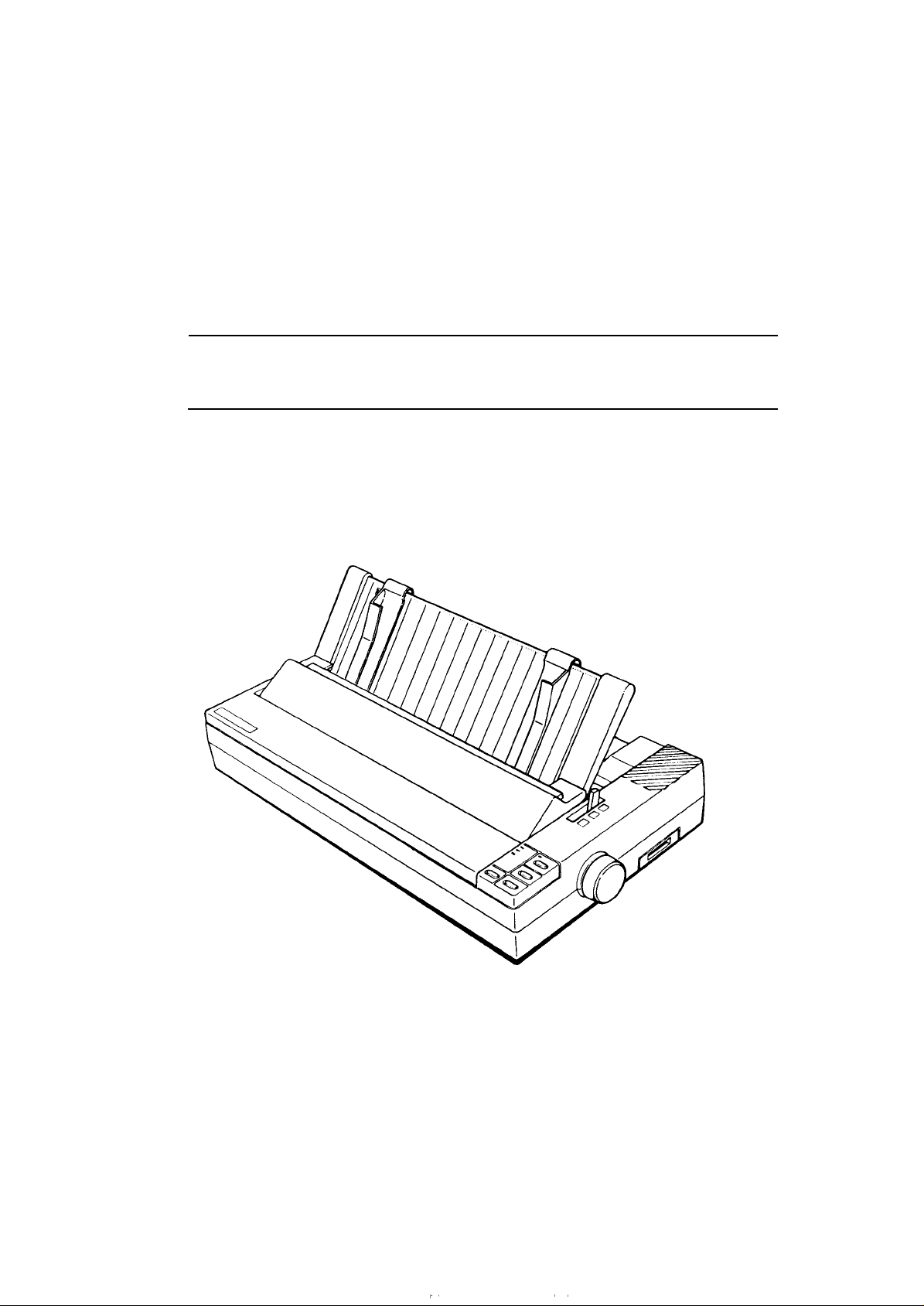
This manual describes functions, theory of electrical and mechanical operations, maintenance, and repair
of LX-105O+.
The instructions and procedures included herein are intended for the experience repair technician, and
attention should be given to the precautions on the preceding page. The chapters are organized as
follows:
CHAPTER 1. GENERAL DESCRIPTION
Provides a general product overview, lists specifications, and illustrates the main components of the printer.
CHAPTER 2. OPERATING PRINCIPLES
Describes the theory of printer operation.
CHAPTER 3. DISASSEMBLY AND ASSEMBLY
Includes a step-by-step guide for product disassembly and assembly.
CHAPTER 4. ADJUSTMENTS
Includes a step-by-step guide for adjustment.
CHAPTER 5. TROUBLESHOOTING
Provides Epson-approved techniques for adjustment.
CHAPTER 6. MAINTENANCE
Describes preventive maintenance techniques and lists lubricants and adhesives required to service the equipment.
APPENDIX
Describes connector pin assignments, circuit diagrams, circuit board component layout and exploded diagram.
The contents of this manual are subject to change without notice.
—
iv —
REVISION SHEET
Revision Issue Date
A
Rev.
May 18, 1994
Revision Page
1st
issue
-v-

TABLE OF CONTENTS
CHAPTER 1.
CHAPTER 2.
CHAPTER 3.
CHAPTER 4.
CHAPTER 5.
CHAPTER 6.
APPENDIX
GENERAL DESCRIPTION
OPERATING PRINCIPLES
DISASSEMBLY AND ASSEMBLY
ADJUSTMENTS
TROUBLESHOOTING
MAINTENANCE
— vi —
Chapter 1
General Description
Table of Contents
FEATURES
1.1
1.2 SPECIFICATIONS
1.2.1
1.2.2
1.2.3
1.2.4
1.2.5
1.2.6
1.2.7
1.2.8
1.2.9
1.3 INTERFACE OVERVIEW
1.3.1 Parallel Interface. . . . . . . . . . . . . . . . . . . . . . . . . . . . . . . . . . . . . . . . . . . 1-8
1.3.2 Optional Interface #8143. . . . . . . . . . . . . . . . . . . . . . . . . . . . . . . . . . . . . 1-9
1.4 PRINTER OPERATIONS
1.4.1
1.4.2
1.4.3
1.4.4
1.4.5
1.4.6
1.4.7
Printing Specifications. . . . . . . . . . . . . . . . . . . . . . . . . . . . . . . . . . . . . . .
Paper Handling Specification. . . . . . . . . . . . . . . . . . . . . . . . . . . . . . . . . .
Paper Specification . . . . . . . . . . . . . . . . . . . . . . . . . . . . . . . . . . . . . . . . .
Ink Ribbon . . . . . . . . . . . . . . . . . . . . . . . . . . . . . . . . . . . . . . . . . . . . . . . .
Environmental Conditions . . . . . . . . . . . . . . . . . . . . . . . . . . . . . . . . . . . .
Electrical Specifications. . . . . . . . . . . . . . . . . . . . . . . . . . . . . . . . . . . . . .
Reliability. . . . . . . . . . . . . . . . . . . . . . . . . . . . . . . . . . . . . . . . . . . . . . . . .
Safety Approval. . . . . . . . . . . . . . . . . . . . . . . . . . . . . . . . . . . . . . . . . . . .
Physical Specifications . . . . . . . . . . . . . . . . . . . . . . . . . . . . . . . . . . . . . .
Control Panel. . . . . . . . . . . . . . . . . . . . . . . . . . . . . . . . . . . . . . . . . . . . . 1-10
SelecType Functions. . . . . . . . . . . . . . . . . . . . . . . . . . . . . . . . . . . . . . . 1-11
MicroAdjustment. . . . . . . . . . . . . . . . . . . . . . . . . . . . . . . . . . . . . . . . . . 1-11
Panel Operational Power ON……. . . . . . . . . . . . . . . . . . . . . . . . . . 1-11
DIP Switch Settings. . . . . . . . . . . . . . . . . . . . . . . . . . . . . . . . . . . . . . . . 1-12
Buzzer Operation. . . . . . . . . . . . . . . . . . . . . . . . . . . . . . . . . . . . . . . . . . 1-14
EEPROM Reset. . . . . . . . . . . . . . . . . . . . . . . . . . . . . . . . . . . . . . . . . . . 1-14
1-1
1-3
1-3
1-5
1-5
1-7
1-7
1-7
1-7
1-7
1-7
1-8
1-1o
1.5 MAIN COMPONENTS
1.5.1 TAMA Main Control Board. . . . . . . . . . . . . . . . . . . . . . . . . . . . . . . . . . . 1-15
1.5.2
1.5.3 Printer Mechanism
Figure 1-1. Exterior View of the LX-105O+. . . . . . . . . . . . . . . . . . . . . . . . . . . . . 1-1
Figure l-2. Pin Configuration. . . . . . . . . . . . . . . . . . . . . . . . . . . . . . . . . . . . . . . 1-2
Figure 1-3. Printable Area — Cut Sheet . . . . . . . . . . . . . . . . . . . . . . . . . . . . . . . 1-5
Figure l-4. PrintableArea -Continuous Paper. . . . . . . . . . . . . . . . . . . . . . . . . 1-6
Figure l-5. Adjust Lever Position. . . . . . . . . . . . . . . . . . . . . . . . . . . . . . . . . . . . 1-6
Figure l-6. Data Transmission Timing . . . . . . . . . . . . . . . . . . . . . . . . . . . . . . . . 1-8
Figure l-7. Control Panel. . . . . . . . . . . . . . . . . . . . . . . . . . . . . . . . . . . . . . . . . 1-10
Figure l-8.
Figure 1-9.
Figure 1-11. Printer Mechanism
TAa Filter Unit… . . . . . . . . . . . . . . . . . . . . . . . . . . . . . . . . . . . . . . . . . 1-16
(M-3D60). . . . . . . . . . . . . . . . . . . . . . . . . . . . . . . . . 1-16
List
TAMA Board Component Layout . . . . . . . . . . . . . . . . . . . . . . . . . 1-15
TAa Filter Unit. . . . . . . . . . . . . . . . . . . . . . . . . . . . . . . . . . . . . . . . 1-16
of Figures
(M-3D60) . . . . . . . . . . . . . . . . . . . . . . . . . . . 1-16
1-15

List of Tables
Table 1-1. Options for
Table 1-2. Print Speed and Printable Columns . . . . . . . . . . . . . . . . . . . . . . . . .
Table l-3.
Table
Table
Table
Table
Table
Table
Table
CharacterTables.
-4. Adjust Lever Settings . . . . . . . . . . . . . . . . . . . . . . . . . . . . . . . . . . . .
-5. Electrical Specifications. . . . . . . . . . . . . . . . . . . . . . . . . . . . . . . . . . .
-6. Connector PinAssignments and Signal Functions. . . . . . . . . . . . . . 1-8
-7. Settings
for DIP Switch . . . . . . . . . . . . . . . . . . . . . . . . . . . . . . . . . . 1-12
-8. International Character Set Selection . . . . . . . . . . . . . . . . . . . . . . . 1-12
-9. Character Table Selection. . . . . . . . . . . . . . . . . . . . . . . . . . . . . . . .
-lO. Page Length Selection . . . . . . . . . . . . . . . . . . . . . . . . . . . . . . . . .
LX-105O+
. . . . . . . . . . . . . . . . . . . . . . . . . . . . . . . . . . . . . . .
. . . . . . . . . . . . . . . . . . . . . . . . . . . . . . . . . . . . 1-1
l-s
I-A
1-6
1-7
1-13
1-13
LX-105O+
Service Manual
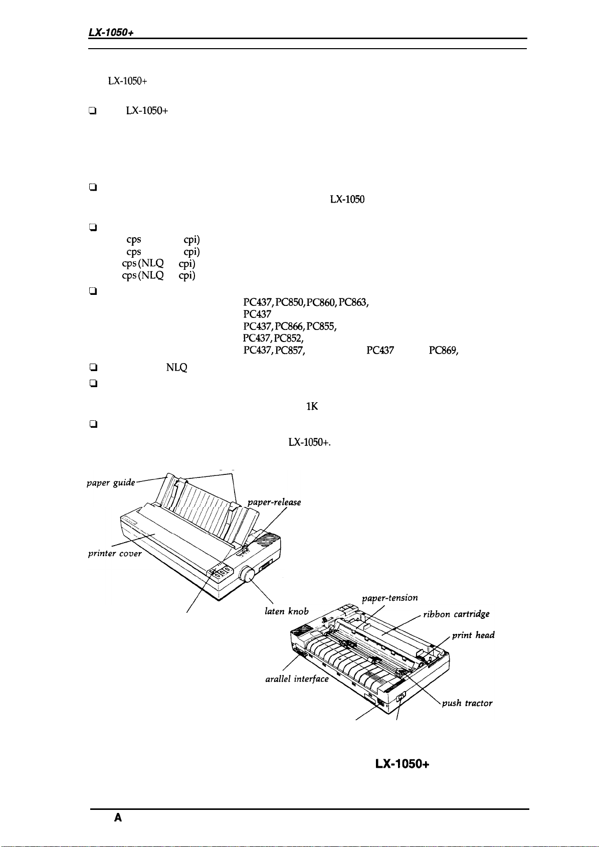
1.1 FEATURES
The
LX-105O+
are:
The LX-105O+ has
Standard version:
India version:
Russian version:
Latin version:
South Europe version:
c1
Command compatible with following printers.
Standard, Latin, and South Europe version: with
Russian and India version:
Q
Printing speeds:
200
240
40
48
Ci
PC table support as follows.
Standard version:
India version:
Russian version:
Latin version:
South Europe version:
Two built-in
c1
c1
Input buffer size is as follows.
Standard, Latin, and South Europe version: 4Kbytes
Russian and India version:
L1
Optional EPSON TYPE-A interface
is a small, light-weight, low-cost, advanced paper handling printer. Its main features
versions. Different parts are Program ROM version only.
four
ROM version SOxxxx
ROM version Slxxxx
cps
(draft 10
cps
(draft 12
cps (NLQ
cps (NLQ
ROM version S2
ROM version S3xxxx
ROM version S4xxxx
cpi)
cpi)
10
cpi)
12
cpi)
Italic,
PC437, PC850, PC860, PC863,
Italic,
PC437
Italic,
PC437, PC866, PC855,
Italic,
PC437, PC852,
Italic,
PC437, PC857,
NLQ
(Near Letter Quality) fonts (Roman and Saris Serif)
XXXX
with FX-1OOO
MAZOVIA, codeMJK
1S0 Latin IT,
IK bytes
LX-105O
Bulgaria
PC865
PC437
Greek,
General Description
PC869,
1S0 8859-7
Figure 1-1 shows the an exterior view of the
edge guides
‘aperguideSp.per-re,e.e
/
control panel
P
P
LX-105O+.
lever
AC inlet’
vaver-tension
/
power switch
unit
Rev.
Figure 1-1. Exterior View of the
A
LX-105O+
1-1
General Description
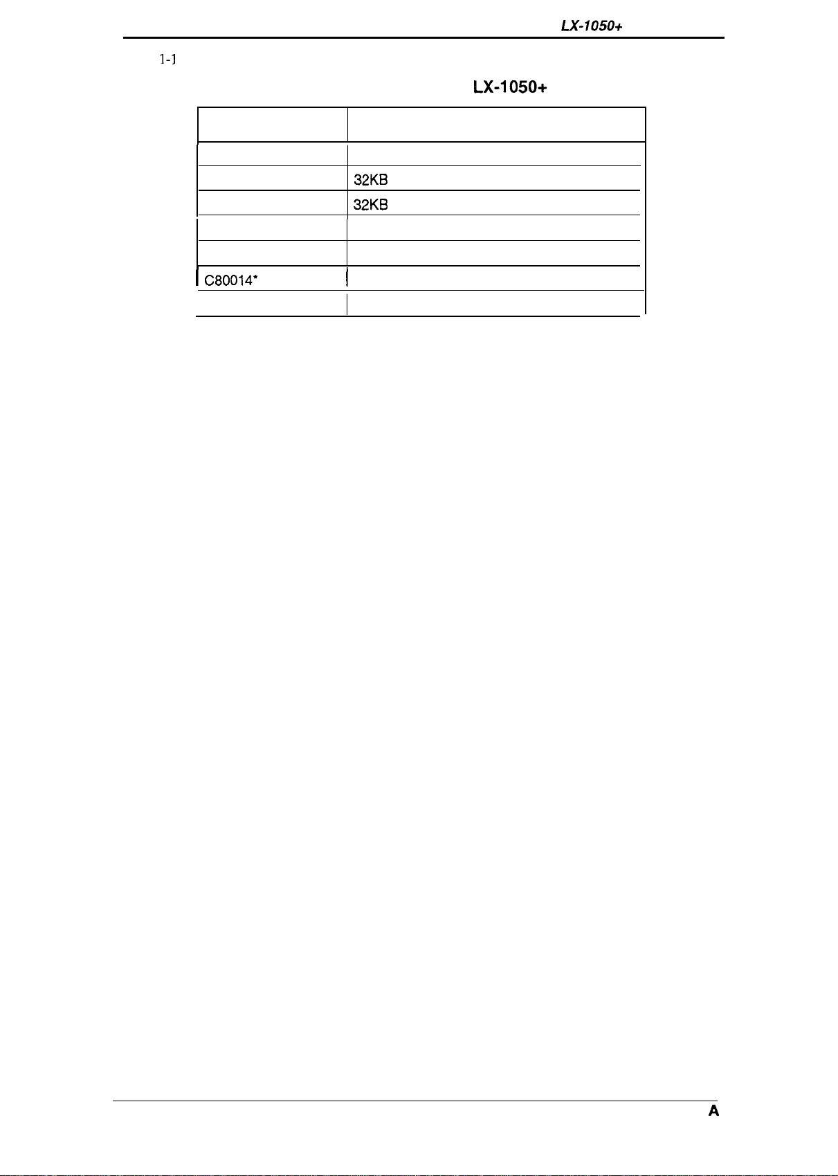
Table
1-1
lists the optional units available
for the LX-1050+.
LX-105O+
Service Manual
Table 1-1. Options for
Cat. No. Description
8143 New Serial Interface Board
C82302*/C82304*
C82303*
8165
C80624* Single Bin Cut Sheet Feeder
i C80014*
8755
32KB Serial Interface
32KB Parallel Interface
IEEE-488 Interface Board
[
PullTractorUnit
Ribbon Cartridge
LX-105O+
1-2
Rev. A
LX-105O+ Service Manual
1.2 SPECIFICATIONS
This section provides detailed statistics for this printer.
1.2.1 Printing Specification
General Description
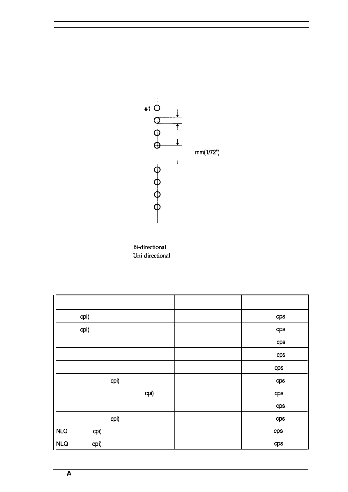
Printing Method:
Pin Configuration: 9 wires (diameter 0.29rnm)
Serial, impact, dot matrix
#1
I
0.29
0.35
mm
mm(l/72”)
#2
#3
b
#4
#5
&—=-
#8
#7
#8
#9
Figure 1-2.
Pin Configuration
Print direction:
Print speed:
Printable columns
Bi-directional
Uni-directional
See Table 1-2.
See Table 1-2.
Table 1-2. Print Speed and Printable Columns
Type of Letters
Pica (10
Elite (12
Double-width pica
Emphasized pica
Double-width emphasized pica
Condensed pica (17
Double-width condensed pica (17
Double-width elite
cpi)
cpi)
cpi)
cpi)
printing with logical seeking (Text mode)
(left to right) printing (Bit image mode)
Printable Columns
136
163
68
136
68
233
115
81
Print Speed
200
Cps
240
CpS
100
Cps
100
Cps
50
Cps
171
Cps
86
Cps
120
Cps
Condensed elite (20
NLQ
NLQ
Rev.
pica (1 O
elite (12
A
cpi)
cpi)
cpi)
272
136
163
200
40
48
Cps
Cps
CpS
1-3
General Description
lot matrix format:
Ytaracter
~haracter
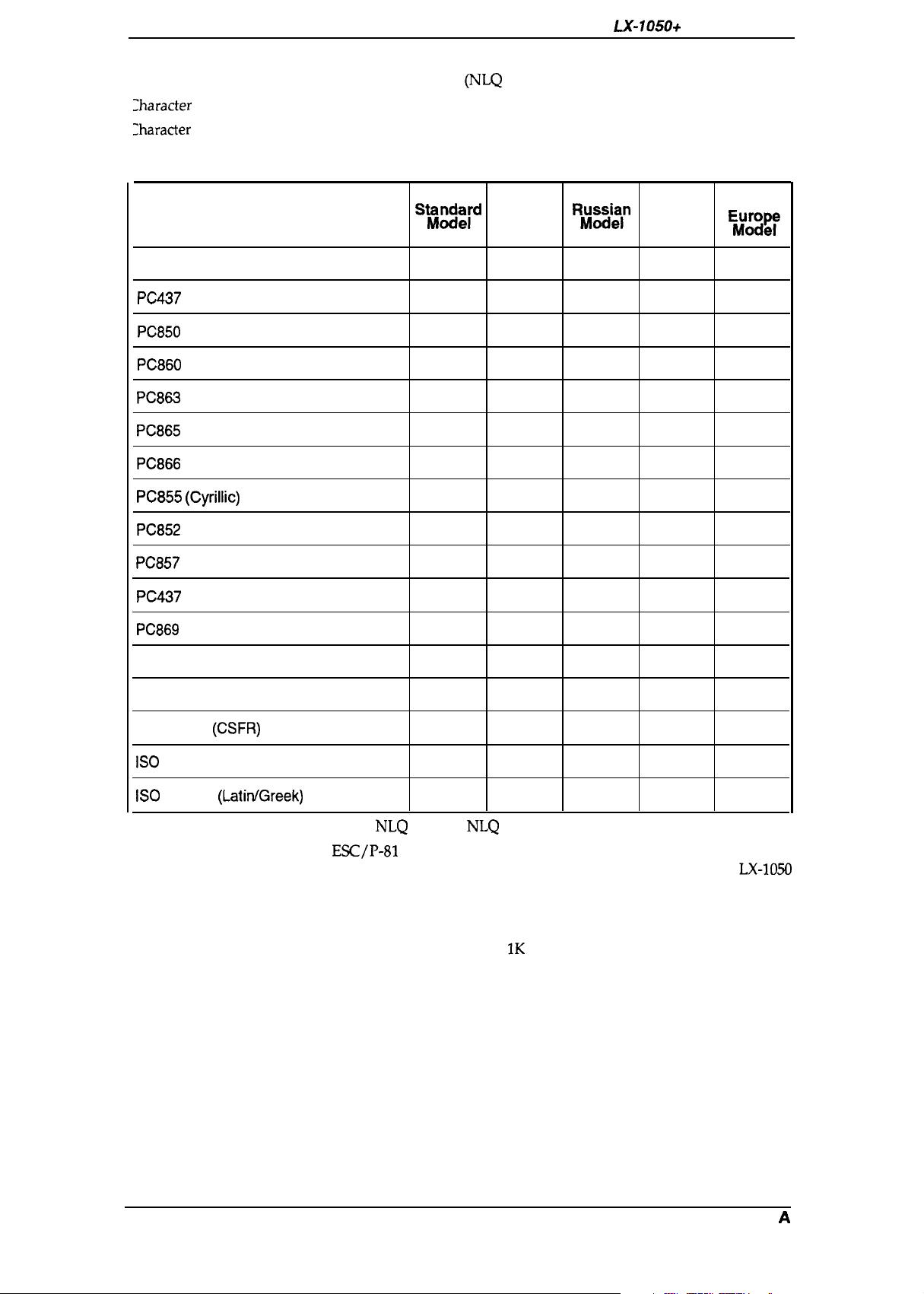
sets:
tables:
9 X 9
Text mode (Draft)
18X 20 Text mode
(NLQ
13 international character sets
See Table 1-3.
Table 1-3. Character Tables
LX-105O+
Service Manual
Character Table
ITALIC
PC437
(US/ Standard Europe)
PC850
(Multilingual)
PC860
(Portuguese)
PC863
(Canadian-French)
PC865
(Nordic)
PC866
(Russian)
PC855 (Cyrillic)
PC852
(East Europe)
PC857
(Turkish)
PC437
Greek
PC869
(Greek)
SW)ck[d
o
o
o
o
o
o
x x
x x
x x x
x x x x
x x x x
India
Model Model
0 0 0
0 0 0
x x
x
x x x
x
l?~su~ln
x
x x
o
o
x x x x
Latin
x
x
x
x
o x
South
E$;mg~
0
0
x
x
x
x
x
x
o
o
o
Bulgaria
MAZOVIA (Poland)
Code MJK
ISO
Latin IT (Turkish)
ISO
8859-7
(CSFR)
(LatitiGreek)
Font:
Control code:
Input buffer:
x
x
x
Saris Serif
o
x
x
x x
x x
x
o x
o x
x
o
o
Draft,
NLQ
x
x x
x
x
x x
Roman,
NLQ
Esc/P-81
Standard, Latin, and South Europe model compatible with
LX-105O
India and Russian model compatible with FX-1OOO (except IBM
mode)
Standard, Latin, and South Europe model: 4K bytes
India and Russian model: IK bytes
1-4
Rev. A
LX-105O+ Service Manual
1.2.2
Paper Handling Specification
General Description
Line spacing:
Line feed speed:
Paper feed method:
Paper insertion:
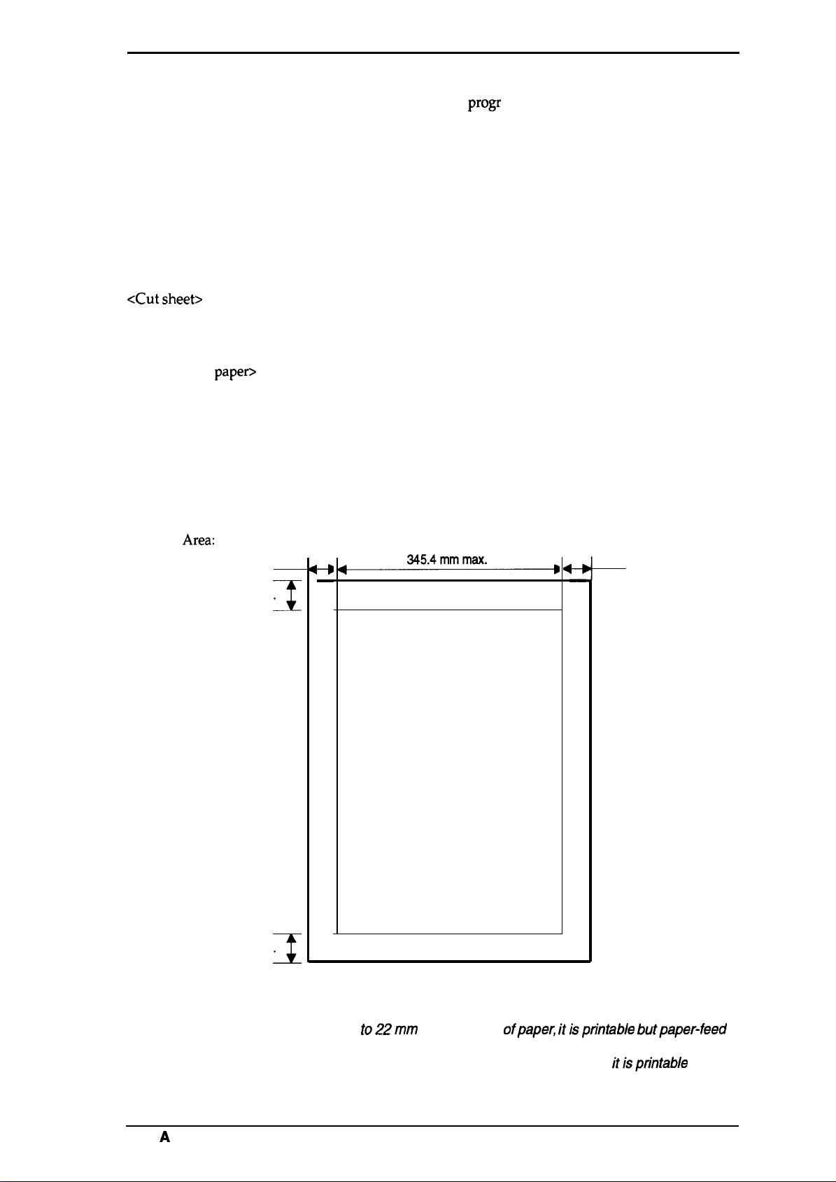
1.2.3 Paper
Useable paper:
<Cut sheet>
<Continuous
<Envelope>
<Label>
Printing
Area:
Specification
paper>
3
22 mm min.
Note 1
mm min.
I
1/6 inch or 1/8 inch, or
Approximately 95 ms (1/6 inch line feed)
Approximately 75 ms (1/6 inch in page feed)
Friction feed
Tractor feed (push tractor: standard, pull tractor: optional)
Rear
Width: 182 to 364 mm (4 to 14.3 inch)
Length: 182 to 364 mm (4 to 14.3 inch)
Thickness: 0.065 to 0.14 mm (0.0025 to 0.055 inch)
Weight: 45 to 78 Kg (14 to 24 lb)
Width: 101 to 406.4 mm (4 to 16 inch)
Copies: 3 sheets (1 original 2 copies)
Total thickness: 0.065 to 0.25 mm (0.0025 to 0.010 inch)
Weight: 45 to 70 Kg (14 to 22 lb)
34 to 50 Kg (12 to 15 lb)— copy paper
Size: No. 6 (166X 92 mm), No.1O (240X 104 mm)
Total thickness: 0.16 to 0.52 mm (0.0063 to 0.0197 inch)
Weight: 39 to 78 Kg (12 to 24 lb)
Size: 63.5 X23.8 mm (2.5 inch X 15/16 inch)
Cut sheet
-#
—
Printable area
progr
ammable in units of 1/216 inch
3
mm min.
t—i
—
Notes:
Rev.
22 mm min.
Note 2
I
Figure 1-3. Printable Area — Cut Sheet
1. In the
2. In the area from 13.5 mm to 22mm from the bottom of the paper, itisptintable but
A
area from
is not assured.
paper-feed is not assured.
8.5
mm
to22mm
from the top ofpapec itisprintable butpaper-feed
1-s
General Description
LX-105O+ Service Manual
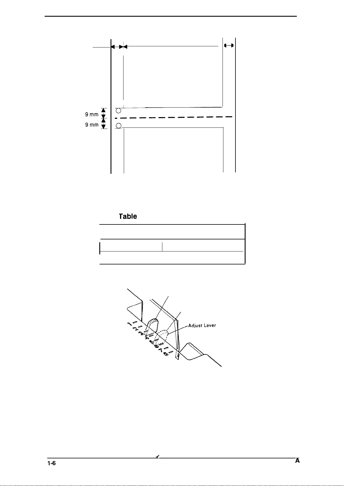
Continuous paper
13 mm min.
Figure 1-4. Printable Area — Continuous Paper
Adjust lever settings
I
345.4
mm max.
➤
4—D
13 mm min.
I
o
Printable area
0
0
0
.————————————
c1
0
0
0
The adjust lever must be set to the proper position for the paper
thickness.
o
0
0
0
0
n
u
0
0
0
Table
Lever position
I
2nd step
I
1-4. Adjust Lever Settings
Paper Thickness
0.06 to 0.18 mm
0.19 to 0.25
2’nd position
4’th position
3rd step
\@
I
I
I
mm
1-6
Figure 1-5. Adjust Lever Position
s?
Rev.
A
LX-105O+
Service
Manual
1.2.4 Ink Ribbon
General Description
Type:
Color:
Reliability:
#8755 Ribbon Cartridge
Black
3 million characters at 14 dots/character
1.2.5 Environmental Conditions
Temperature:
Humidity:
Resistance to shock:
Resistance to vibration:
-30 to60“C — Storage
5to35“C — Operation
5 to 85
10to801%0
2 G, 1 ms — Storage
1 G, 1 ms — Operation
0.50 G (55 Hz max.) — Storage
0.25 G (55 Hz max.) — Operation
YO RH
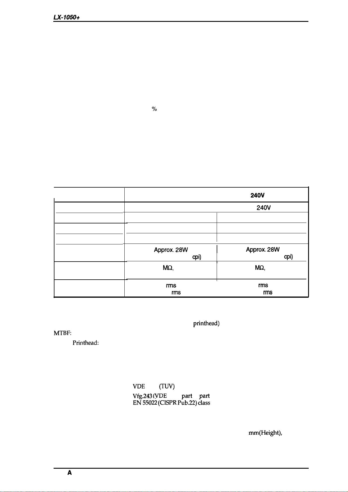
1.2.6 Electrical Specifications
Table 1-5. Electrical Specifications
I
Rated voltage
Input voltage range
Rated frequency range
Input frequency range
Power consumption
Insulation resistance
Item
(between AC line and chassis)
120V Version
103.5
49.5 to 60.5 Hz
Approx. 28W
(Self test in draft 10
(no
condensation) — Storage
RH
(no
condensation) — Operation
120 V AC
to 132V
50 to 60 Hz
10
M(2,
min.
cpi)
220-
240V
I
I
I
1
(between AC line and chassis)
220-
49.5 to 60.5 Hz
Approx. 28W
(Self test in draft 10
Version
240V
AC
198 to 264V
50 to 60 Hz
10
MQ,
min.
cpi)
Dielectric strength
AC 1000 V
or AC 1200 V
1.2.7 Reliability
MCBF:
MTBF:
Life of
Printhead:
3 million lines (except
6000 POH
200 million strokes/wire
1.2.8 Safety Approval
Safety Standards:
RFI:
UL4785th(U.S. version)
CSA22.2 #220. (U.S. version)
VDE
0806
VfR.243 (VDE
E~550~ (CISPR P~b.22) ~lass
1.2.9 Physical Specifications
Dimensions
Weight
619.3 mm (Width)
excluding knobs
8.80 Kg
rms
1 minute
rms
1 second
printhead)
(TIN)
(European version)
0878
Part
3,
x 339 mm
I
Part
30)
B”
(Depth) x 141
AC
1250
V
rms
or AC 1500 V
mm(Height),
1 minute
rms
1 second
Rev.
A
General Description
1.3 INTERFACE OVERVIEW
The
LX-105O+
■
■
is equipped with the following external interfaces;
Centronics parallel interface
Optional Type A interface
LX-105O+
Service Manual
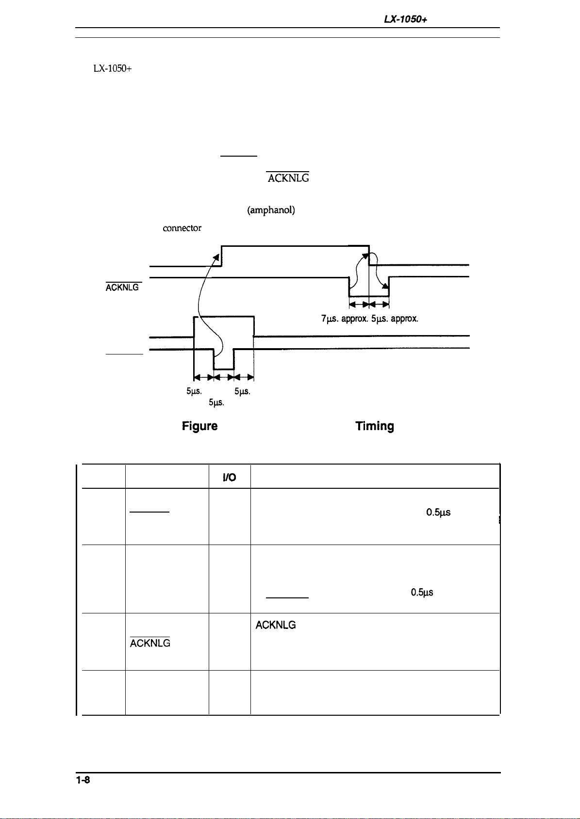
1.3.1
Parallel InterFace
Data Format
Synchronization
Handshaking
Signal Level
Adaptable Connector
Table 1-6 shows the
BUSY
ACKNLG
DATA
STROBE
comector
8-bit parallel
By STROBE pulse
By BUSY and
ACKNLG
signal
Ill-compatible
57-30360
(arnphanol)
or equivalent
pin assignments and signal functions of the parallel interface.
$1
/
5ps.
\
min.
5ps.
5w.
min.
min.
7p.a. approx. 5ps. approx.
Pin No.
1
2-9
10
11
Figure
Table 1-6. Connector Pin Assignments and Signal Functions
Signal Name
STROBE
1-6. Data Transmission
1/0
The STROBE pulse is used to read data from the host
computer. The pulse width must be
I
Normally, it is HIGH, and data is latched with rising
Timing
Description
0.5p.s
edge of this signal.
DATA 1-8 are parallel data bits. When one of these
signals is HIGH, the data bits is 1; when LOW, the data
bits is O. The most significant bit ( MSB) is data 8. The
DATA 1-8
I
signal state must be maintained for
0.5ps
on either side
of STROBE signal’s active edge.
ACKNLG
ACKNLG
approximately 10P.s. This signal goes LOW upon the
o
completion of data reception, to indicates that the printer
is an acknowledge pulse with a width of
is ready to receive further data.
The BUSY signal informs the host computer of the
o
BUSY
printer’s status. When this signal is HIGH, the printer
cannot accept further data.
or more.
~i
1-8
Rev. A

LX-105O+
Sewice Manual
General Description
Table 1-6. Connector Pin Assignments
—. . .
Pin No.
12
13
14
15
16
17
18
19-30
31
Signal Name
PE
SLCT
AUTO FEED XT
NC
GND Signal ground
CHASSIS
GND
NC
GND Twisted-pair return signal ground.
INIT
1/0
o
o
1
.
I
This signal indicates whether paper is available in the
printer or not. A HIGH level indicates a no paper
condition.
pulled up to +5V though
If this signal is set to LOW, the printer automatically
performs one line feed upon receipt of a CR (carriage
return) code.
Not
USSd.
Chassis ground.
Not
USSd.
If this signal goes LOW, the printer is initialized. The
pulse width of this signal must be
. -. . — . .
and
Signal Functions (Cont.)
Description
3.3KQ
resistor in the
50p.s
or more.
.- . .
print,er.
,
32
33
34
ERROR
o
GND Signal ground.
NC
35 +5V
36
Notes:
IN
A// interface conditions are based on
must be
The AUTO FEED-XT signal can be set LOW by DIP
The SELECT IN signal can be set LOW by jumper 1.
/ess than
0.2 p.s.
I
SLCT
1.3.2 Optional Interface #8143
The
LX-105O+
Tyep:
Synchronization:
Protocol:
Transfer speed:
can use the non-intelligent serial interface board #8143.
RS-232C
Asynchronous start-stop system
Start bit: 1 bit
Stop bit: 1 bit or more
Data length: 7 or 8 bits
Parity:
X-ON/X-OFF or DTR control
75,110,134.5,150,200, 300,600,1200,1800,2400, 4800, and 9600
This signal goes LOW if the printer:
—
has a fatal error.
— runs out of paper.
— off line.
Not
Used
Pulled up to +5 V through 3.3
The
DC1/DC3
code is only valid when this signal is
KQ
HIGH.
7ZL
/eve/s. Both the rise
sw”tch
andfa//
2-4.
or current loop
Odd, Even or none
resistor in the printer.
times of all signals
Rev.
A
1-0
General Description
LX-105O+ Service Manual
1.4 PRINTER OPERATIONS
This section describes the basic operations of the printer.
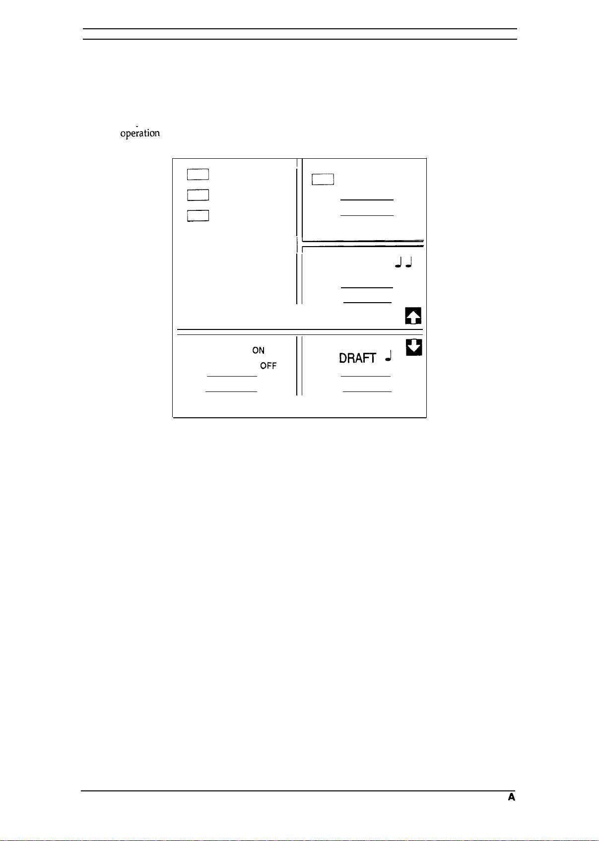
1.4.1 Control Panel
The control panel of this printer contains four non-lock type push buttons and four LED indicators
for easy
[Buttons]
ope;ation
of the various printer function.
D
POWER
D
READY
m
PAPER
OUT
0
ON LINE
OFF LINE
ON LINE:
FORM FEED:
LINE FEED:
LOAD/EJECT:
CONDENSED
LOAD/EJECT
ON
OFf=
J
J J
II
I I
II
NLQ
ROMAN
SANS SERIF J J J
FORM FEED
LINE FEED
JJ
~
Figure 1-7. Control Panel
Switches printer status between on line and offline.
When the
or to advance continuous paper to the top of the next page.
When the printer is off line, press this button to advance the paper one line,
or hold it down to advance the paper continuously.
This button is used to feed the paper to the loading position, or to eject paper
that is already loaded. Paper is ejected forward if the paper-release lever is
set to the single-sheet position, or is ejected backward (removed from the
paper path) if the release lever is set to the continuous paper position.
printer is off line, press this button to eject a single sheet of paper
[Indicators]
POWER:
READY:
PAPER OUT:
ON LINE:
1-10
On when the power switch is on and power is supplied.
On when the printer is ready to accept input data. Flickers while data is
printed.
On when the printer is out of paper or when continuous paper ia in a
standby position. The printer also beeps when it is out of paper.
On when the printer is on line and ready to accept data from the computer.
When this indicator is blinking, the micro-adjustment feature can be used.
Rev.
A
LX-105O+ Service Manual
General Description
1.4.2
SelecType
selection of Draft, Roman, or Saris Serif fonts and selection of normal printing or condensed
printing modes.
To select Roman or Saris Serif, press the
pressed. When it sounds twice, the Roman font is selected. When it sounds three times, the Saris
Serif font is selected.
To select the Draft font, press the DRAFT button. The buzzer will sound once, indicating that the
DRAFT
To set for condensed printing when the printer is in the print mode, press the CONDENSED button
once (the buzzer will sound once), and the printer will enter the condensed print mode.
To cancel condensed printing, press the CONDENSED button again. After you press the button,
the buzzer sounds twice to tell you that condensed printing is canceled.
SelecType
allows the user to choose fonts and the printing mode easily. This function provides for
font is selected.
Functions
SelecType
is effective only when the printer is ON LINE and not printing.
NLQ
button. A buzzer sounds when the
NLQ
button is
1.4.3 Micro Adjustment
By pressing the FORM FEED or LINE FEED buttons immediately after loading paper or when
using the tear-off feature, you can make tine adjustment to the loading and tear-off positions.
1.4.4 Panel Operation at Power ON
The following functions can be activated at power on by holding down the specified button on the
control panel.
Self-test mode:
Hex Dump mode:
To begin printing the self-test in the Draft mode, turn the printer ON while
pressing the LINE-FEED button. To begin printing the self-test using the
NLQ
mode (Near Letter Quality), press FORM FEED and hold it down, then
turn the printer power ON.
Self-test printing can be stopped or started by pressing ON-LINE (ON-LINE
indicator is not lit). To finish the self-test, stop the printing by pressing the
ON-LINE switch then turn OFF the printer power.
The firmware revision number is printed as the first line of the self-test, and
subsequently, current DIP switch settings are printed.
The printer enters the HEX-DUMP mode when it is powered on while the
LINE-FEED and FORM-FEED buttons are pressed down.
In the HEX-DUMP mode, the hexadecimal representation of the input data is
printed out, along with corresponding ASCII characters. This function is
valuable for checking the data the printer has received from the host. If input
data is a control code rather than a character code, a period (.) is printed in
the ASCII column.
Rev.
A
1-11
General Description
L.X-1050+
Service Manual
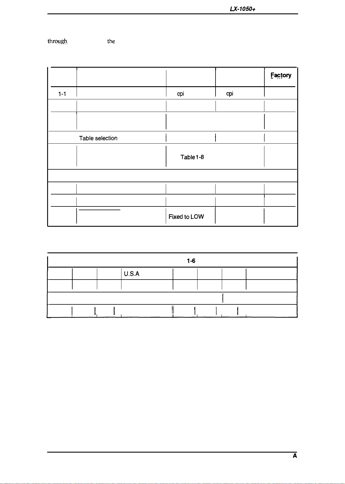
1.4.5 DIP Switch Settings
The two DIP switches are located on the side of the printer and function as shown in Tables 1-7
throum
the
1-10. Note
INIT signal.
that
the
status of the DIP switches is read only at power on or upon receipt of
Table 1-7. Settings for DIP Switch
SW No.
1-1
I
Character
Description
Pitch
I
12
cpi
ON
I
10
cpi
OFF
I
Faoto~
Settings
OFF
1-2
Shape of Zero
1
1-3
1-4
1-5 I
1-6
1-7
1-8 ON
2-1
2-2
Page length
Tableselection
Character table selection
Short tear-off Invalid
Cut sheet feeder control
I
2-3
Skip over perforation 1 inch
0
1
See Table 1-10.
I
Graphics
See Table
1-8
Valid
I I
1
2-4
AUTO FEED XT signal internally
fixed or not
Fixd t. Low
0
I
Italics
or 1-9.
Valid
Invalid
None
I
Depends on
external signal
I
I
OFF
I
I
1
Table 1-8. International Character Set Selection (DIP SW 1-5: OFF)
1+
Sw 1-6 Sw 1-7 Sw 1-8
Country Sw
Sw 1-7 Sw 1-8 Country
OFF
OFF
OFF
ON
ON
OFF
OFF
OFF
OFF
ON ON ON
ON ON
ON
OFF ON Germany
I
ON I OFF
OFF
I
OFF
U.S.A
France
I
U.K.
OFF
OFF
OFF
II
II
OFF I OFF I OFF I Spain
ON ON
ON
OFF I ON
I
OFF Sweden
Denmark
Italy
1-12
Rev.
A
LX-105O+
Service
Manual
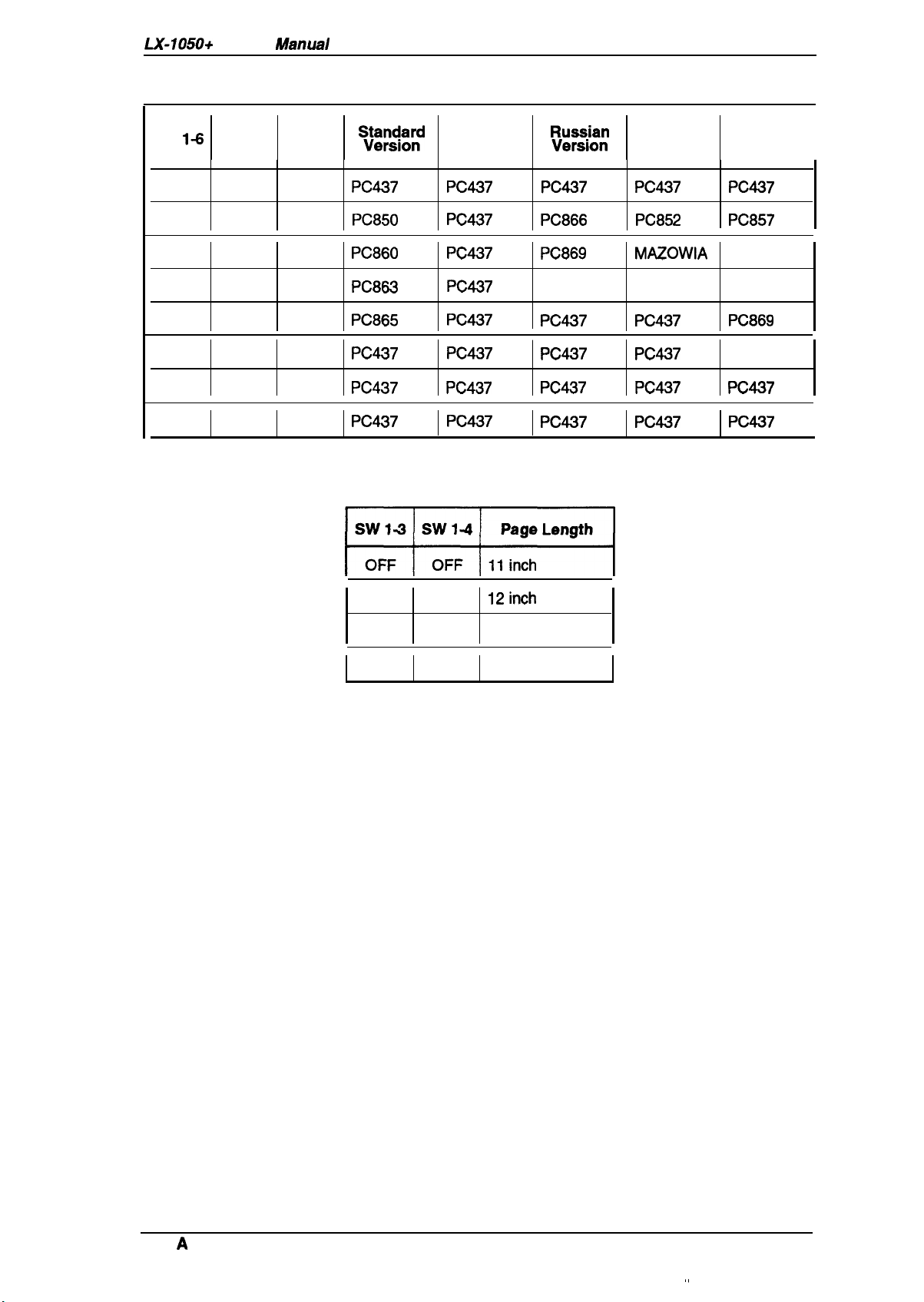
Table 1-9. Character Table Selection (DIP SW 1-5: ON)
General Description
Sw
1-6
Sw 1-7
ON ON ON
ON ON
ON
ON
OFF ON ON
OFF
OFF
OFF
OFF
OFF
ON
OFF ON
OFF
Sw 1-8
OFF
ON
OFF
OFF
OFF
~:pj:;d
PC437 PC437
PC850 PC437
PC860 PC437
PC863 PC437
PC865 PC437
PC437 PC437
PC437 PC437
PC437 PC437
Table
1-10. Page Length Selection
w
India
version
:?:/::
PC437
PC866
PC869
Bulgaria
PC437 PC437 PC869
PC437 PC437 1S088597
PC437 PC437 PC437
PC437 PC437 PC437
Latin
Version
PC437 PC437
PC852
MAZOWIA
Code MJK PC437G.
South
Europe
Version
PC857
ISO Lat. IT
I
I
ON
OFF
ON ON
OFF
ON
12inch
8.5 inch
70/6
inch
Rev.
A
,,
1-13
General Description
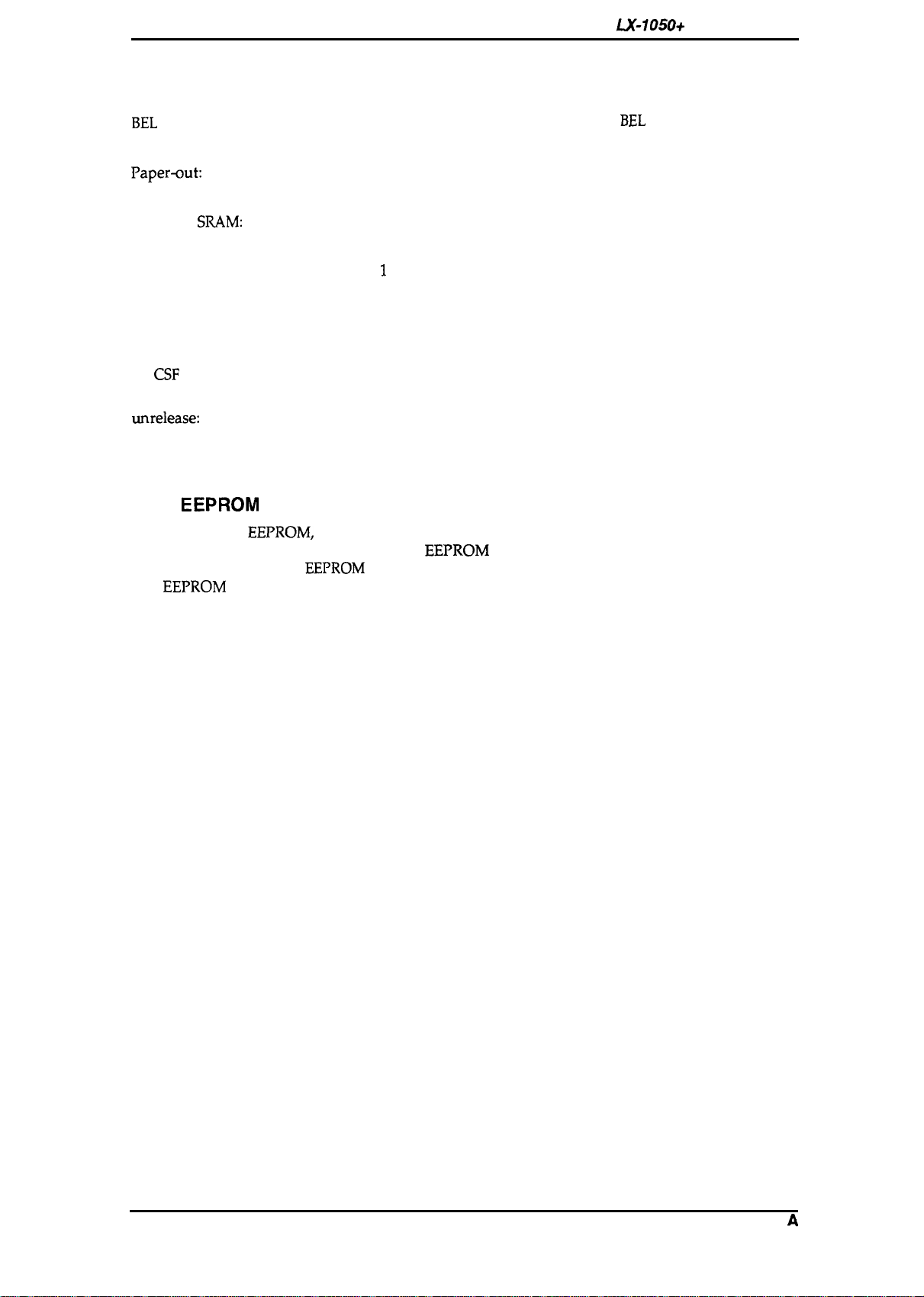
1.4.6 Buzzer Operation
The
buzzer sounds under the following conditions:
LX-105O+
Service Manual
BEL
code:
Carriage trouble:
PaperQut:
Abnormal voltage:
Incorrect
SRAM:
Incorrect RAMinside CPU:
Recognition of panel
The buzzer sounds for 0.1 second when a
Beeps 6 times, pausing briefly after 3rd beep.
Beeps 20 times, pausing briefly after every 4 beeps.
Beeps 5 times, pausing after every beep.
Beeps 8 times, pausing briefly after every 2 beeps.
Beeps indefinitely until power OFF.
Beeps 1 or 2 or 3 times in setting print mode.
operation:
Factory setting:
Beeps once when the value under micro-adjusting is equal to the
factory-set value.
Sheet ejection failure
(in
CSF
mode):
Illegal paper release/
unrelease:
Beeps 20 times, pausing briefly after every 4 beeps.
Beeps continuously when the paper release lever is changed when
the paper is in the paper path.
Beeps until the lever is changed again or the paper is completely out
of the path.
1.4.7
This printer has
EEPROM
Reset
EEPROM,
it memorized SelecType settings, position of continuous paper, and
bi-directional printing adjustment value.
main board replacement,
The
EEPROM
is cleared, when the printer power on while FF and LOAD/EJECT switches are
EEPROM
replacement, or printer mechanism replacement.
pressed.
EEPROM
BEL
code is input.
reset operations are only required after the
1-14
Rev.
A
LX-105O+
Service Manual
1.5 MAIN COMPONENTS
Ganeral
Description
The main
components
of the
LX-105O+
printers are designed for easy removal and replacement to
maintain/repair the printers.
The main components are:
Cl TAMA
D
TAPNL-W control panel: Control panel.
Cl
TAa filter unit: Transformer and filter board.
D M-3D60:
board: Main control board. The CPU on this board controls all main functions.
Printer mechanism.
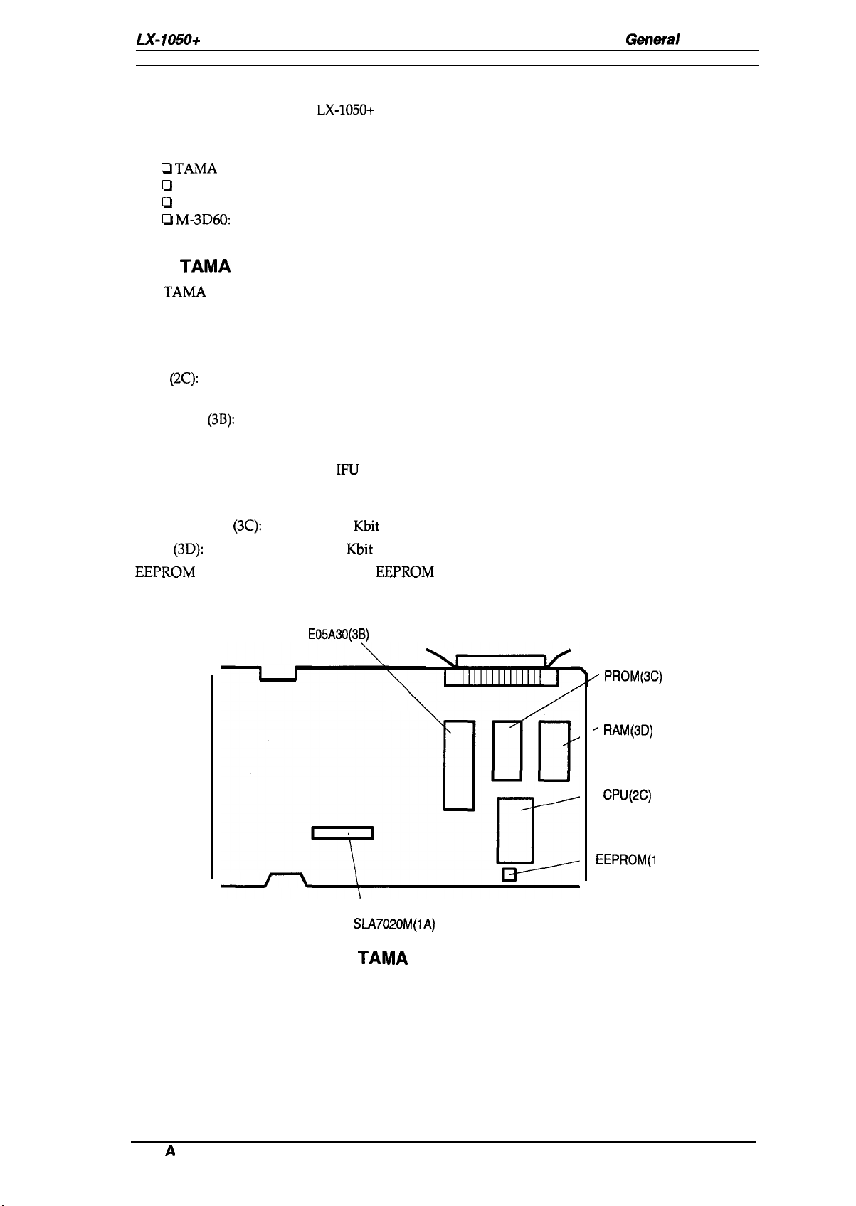
1.5.1 TAMA Main Control Board
The
TAMA
board is the main controller of this printer. It takes charge of interfacing with the host
computer and processing of received print data, as well as control of the whole printer mechanism.
This-board consists of the following components.
CPU
(2C):
Gate-array
Program ROM
RAM
EEPROM
(3B):
(3C):
(3D):
(lC):
CR Motor driver (1A): SLA7020M
8-bit CPU (PPD781OHG)
15 MHz operation clock
E05A30
Includes the following functions:
— MMU (Memory Management Unit)
—
IFU
(Interface Control Unit)
— PCU (1/0 Port Control Unit)
— Head control unit
256
Kbit
EPROM or mask ROM
64
Kbit
PS RAM
256 bit
EEPROM
GA
E05A30(3B)
“ PROM(3C)
“ RAM(3D)
—
CPU(2C)
—
EEPROM(l
SLA7020M(1A)
Figure 1-8. TAMA Board Component Layout
C)
Rev.
A
1-15
General Description
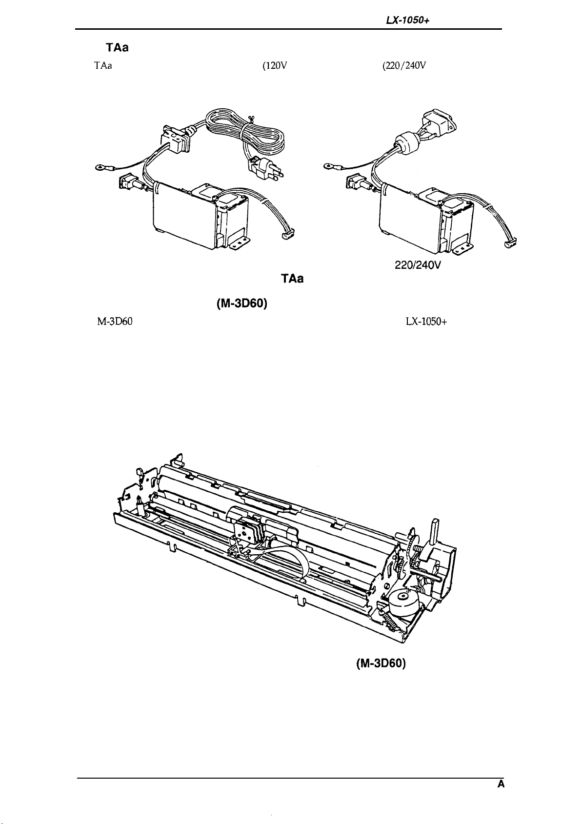
TAa
1.5.2
The
TAa
Filter Unit
filter unit contains a power cord
(120V
Version) or AC inlet
switch, fuse filter circuit, and power transformer.
LX-105O+
(220/240V
Service Manual
Version), power
120V Version
Figure 1-9. TAa Filter Unit
1.5.3 Printer Mechanism (M-3D60)
The
M-3D60
components include:
Carriage motor
Carriage mechanism
Paper feed motor
Paper feed mechanism
Ribbon feed mechanism
Printhead
Sensors
printer mechanism was developed specifically for the
220/240V Version
LX-105O+
printer. Its
1-16
Figure 1-10. Printer Mechanism (M-3D60)
Rev. A
Chapter 2 Operating Principles
Table of Contents
2.1 OVERVIEW
2.2 OPERATING PRINCIPLES OF THE PRINTER MECHANISM
2.2.1 Printhead Printing Operation . . . . . . . . . . . . . . . . . . . . . . . . . . . . . . . . . . 2-2
2.2.2 Carriage Drive Mechanism . . . . . . . . . . . . . . . . . . . . . . . . . . . . . . . . . . . 2-3
2.2.2.1 Home Position Sensor . . . . . . . . . . . . . . . . . . . . . . . . . . . . . . . . 2-3
2.2.3 Paper Feed Mechanism Operation . . . . . . . . . . . . . . . . . . . . . . . . . . . . . 2-4
2.2.3.1 PaperEndSensor. . . . . . . . . . . . . . . . . . . . . . . . . . . . . . . . . . . . 2-6
2.2.3.2 Release Sensor.. . . . . . . . . . . . . . . . . . . . . . . . . . . . . . . . . . . . . 2-6
2.2.4 Ribbon Advance Mechanism . . . . . . . . . . . . . . . . . . . . . . . . . . . . . . . . . . 2-7
2.3 OPERATING PRINCIPLES OF THE ELECTRICAL
2.3.1 Operating Principles of the Power Supply Circuit . . . . . . . . . . . . . . . . . . 2-8
2.3.2 Operating Principles of the Main Control Circuit . . . . . . . . . . . . . . . . . . . 2-9
2.3.2.1
2.3.2.2
2.3.2.3
2.3.2.4
2.3.2.5
2.3.2.6
2.3.2.7
Reset Circuits.. . . . . . . . . . . . . . . . . . . . . . . . . . . . . . . . . . . . . 2-10
Sensor Circuit . . . . . . . . . . . . . . . . . . . . . . . . . . . . . . . . . . . . . . 2-11
Carriage Motor Drive. . . . . . . . . . . . . . . . . . . . . . . . . . . . . . . . . 2-11
Paper Feed Motor Drive Circuit. . . . . . . . . . . . . . . . . . . . . . . . . 2-12
Printhead Drive Circuit . . . . . . . . . . . . . . . . . . . . . . . . . . . . . . . 2-13
Host Interface.. . . . . . . . . . . . . . . . . . . . . . . . . . . . . . . . . . . . . 2-14
EEPROM
Circuit. . . . . . . . . . . . . . . . . . . . . . . . . . . . . . . . . . . . 2-15
CIRCUITRIES
2-1
2-1
2-8
List of
Figure 2-1
Figure 2-2
Figure 2-3. Carriage Drive
Figure2-4. Home Position Sensor Mechanism . . . . . . . . . . . . . . . . . . . . . . . . . 2-3
Figure 2-5. Friction Feed Operation.. . . . . . . . . . . . . . . . . . . . . . . . . . . . . . . . . 2-4
Figure 2-6. Tractor Feed Operation . . . . . . . . . . . . . . . . . . . . . . . . . . . . . . . . . . 2-5
Figure 2-7. Paper End Sensor Mechanism . . . . . . . . . . . . . . . . . . . . . . . . . . . . 2-6
Figure 2-8. Release Sensor Mechanism . . . . . . . . . . . . . . . . . . . . . . . . . . . . . . 2-6
Figure2-9. Ribbon Feed Mechanism . . . . . . . . . . . . . . . . . . . . . . . . . . . . . . . . 2-7
Figure 2-10. Power Supply Circuit Block Diagram. . . . . . . . . . . . . . . . . . . . . . . 2-8
Figure2-11. Main Control Circuit Block Diagram. . . . . . . . . . . . . . . . . . . . . . . . 2-9
Figure2-12. Data Flow . . . . . . . . . . . . . . . . . . . . . . . . . . . . . . . . . . . . . . . . . . . 2-9
Figure 2-13. Reset Circuit . . . . . . . . . . . . . . . . . . . . . . . . . . . . . . . . . . . . . . . . 2-10
Figure 2-14
Figure 2-15
Figure 2-16
Figure 2-17
Figure 2-18
Figure 2-19
Block Diagram of the Printer Mechanism . . . . . . . . . . . . . . . . . . . . 2-1
Printhead-Printing Operation . . . . . . . . . . . . . . . . . . . . . . . . . . . . . . 2-2
M~chanism
Sensor Circuit . . . . . . . . . . . . . . . . . . . . . . . . . . . . . . . . . . . . . . . 2-11
Carriage Drive Circuit Block Diagram . . . . . . . . . . . . . . . . . . . . . 2-11
Paper Feed Motor Drive Circuit. . . . . . . . . . . . . . . . . . . . . . . . . . 2-12
Printhead Drive Circuit Block Diagram . . . . . . . . . . . . . . . . . . . . 2-13
Host Interface.. . . . . . . . . . . . . . . . . . . . . . . . . . . . . . . . . . . . . . 2-14
EEPROM
Circuit . . . . . . . . . . . . . . . . . . . . . . . . . . . . . . . . . . . . . 2-15
Figures
. . . . . . . . . . . . . . . . . . . . . . . . . . . . . . . 2-3

List
of Tables
Table 2-1. Ribbon-Feed Gear Train. . . . . . . . . . . . . . . . . . . . . . . . . . . . . . . . . . 2-7
.
Table 2-2. Voltage Applications . . . . . . . . . . . . . . . . . . . . . . . . . . . . . . . . . . . .
Table 2-3.
Table 2-4. Phase-Excitation Method . . . . . . . . . . . . . . . . . . . . . . . . . . . . . . . .
Functionsofthe
Main
ICand Circutis
. . . . . . . . . . . . . . . . . . . . . . . 2-10
2-8
2-11

LX-105O+
Service Manual
Operating Principles
2.1 OVERVIEW
This section describes the operating principles of the printer mechanism and the electrical circuits
of the
LX-105O+.
2.2
OPERATING PRINCIPLES OF THE PRINTER MECHANISM
The
LX-105O+
carriage drive mechanism, and various sensors. The figure below shows a block diagram of the
printer mechanism.
printer mechanism is composed of the
printhead
unit, paper feed mechanism,
Printhead
Q
. . . . . . . . . . . . . . . .
Phase
v
Stepper Motor
Carriage Drive
I
1160nlStep
or
ll120*lStep
CR HOME
A
carnage
Home
1
Phase
v
Stepper Motor
Paper
Feed
I
11216
’lStep
I
PE
A
Paper End
1
Figure 2-1. Block Diagram of the Printer Mechanism
RELEASE
FRICTIOtV
TRACTOR
Release
Lever
Position
Rev.
A
2-1
Operating Principles
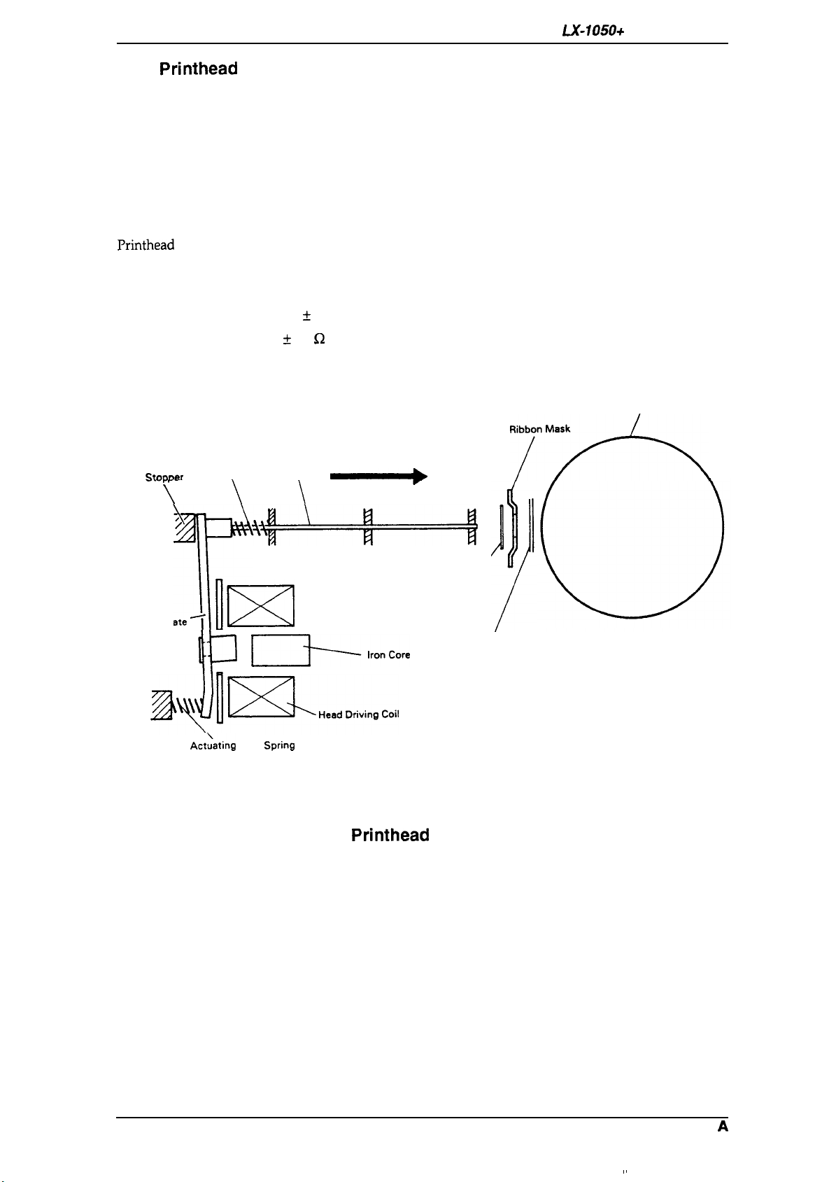
2.2.1 Printhead Printing Operation
The dot-wire operation during printing is as follows. When the head-driving coil for a dot wire is
energized, the actuating plate, which is engaged to one end of the dot wire, is attracted to the iron
core, and drives the dot wire toward the platen. The dot wire forcefully pushes both ribbon and
paper against the platen, causing a dot to be printed.
When the head-driving coil is deenergized, the actuating plate spring causes the actuating plate to
return to its initial position. After striking the platen, the dot wire also returns to its initial position,
partly in response to the impact energy, and partly as a result of the wire-resetting spring. The dot
wire then remains engaged to the actuating plate until it is driven again.
LX-105O+
Service Manual
Printhead
Solenoids:
Wire Diameter:
Drive Voltage:
Coil Resistance:
specifications areas follows:
Wire Resetting Spring
Stnnner
.-.
-r
F-
\
‘4P+—+1
Actuating Plate
~
T
9 solenoids
0.29 mm
24 VDC * 10Yo
19.2 ~ 1.0
Dot Wire
\
\
\
fi2
\
at 25° C
Ilxl
cl—k-e
/
Ribbon
Platen
‘7”*
Paper
~~l~HeadDrivin9Coi,
!’
Act;ating plate
SPrin9
Figure 2-2. Printhead Printing Operation
2-2
Rev.
A

LX-1050+ Service Manual
2.2.2 Carriage Drive Mechanism
Operating Principles
The carriage mechanism includes the
and the platen.
The timing belt is connected to the bottom of the carriage. The belt is driven by the carriage motor
and moved via the beltdriven pulley. The
unit is moved right and left along the carriage guide shaft and plate.
Carriage motor specifications are as follows:
Type:
Drive Voltage:
Coil Resistance:
Current Driving:
4-phase, 48-pole step motor
24 V
k
MY/o
11 G2
k
77.
0.36 A *
0.28 A
Holding: 0.09 A
IO%(Typical)
* IO%(Typical)
at
25°C
printhead,
f IWO
the carriage, the timing belt, the carriage motor,
printhead
(Draft Printing)
(NLQ Printing)
-%’”
is mounted on the carriage, and the entire
Left
.carr-
Figure 2-3.
2.2.2.1
Following figure shows the home position sensor. The sensor switch is ON when
the home position.
Home
Position Sensor
Carriage Drive
Mechanism
the carriage is at
Rev.
Figure 2-4. Home Position Sensor Mechanism
A
2-3
Operating Principles
LX-105O+
Service Manual
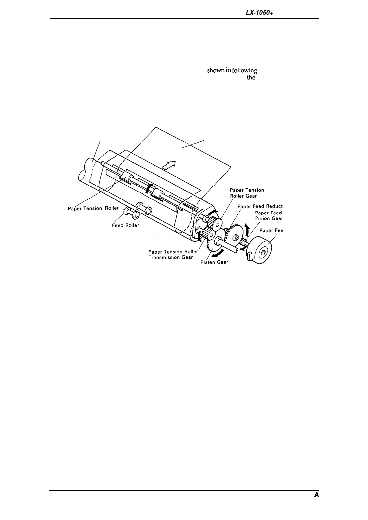
2.2.3 Paper Feed Mechanism Operation
Friction feeding is used for cut sheets, and push tractor feeding is used for fanfold paper.
Friction-Feed Operation
The paper is held against the platen by paper-feed rollers. The paper-feed motor rotates the platen
gear, via the paper-feed reduction gear, in the direction
friction between the paper-feed rollers and the platen, the rotation of
paper to be fed. The feeding direction is indicated by the arrow in the Figure.
The paper is held against the platen by the spring force of the paper-feed rollers, and can be
released by shifting the paper-release lever forward.
shown in following
the
platen gear causes the
figure. Because of the
Platen
,ap~en,ion
Paper
,O,,er
paper (Cut Sheet)
p
,(
Figure 2-5. Friction Feed Operation
ion Gear
Motor
d Motor
2-4
Rev.
A
Loading…
Main
SEIKO EPSON CORPORATION
PRECAUTIONS
DANGER WARNING
PREFACE
Page
TABLE OF CONTENTS
Chapter 1
General Description List
1.1 of Figures
List of Tables
1.1 FEATURES aperguideSp.per-re,e.e
Figure 1-1. Exterior View of the LX-105O+
Table 1-1. Options for
LX-105O+ 1.2 SPECIFICATIONS
b 40
&—=-
Pin Configuration Table 1-2. Print Speed and Printable Columns
Table 1-3. Character Tables x x x x o
1-4
1.2.2 I
I Paper Handling Specification
1.2.3 Paper Specification
c1
1.2.4 Ink Ribbon I
1.2.5 Environmental Conditions M(2,
1.2.6 Electrical Specifications Table 1-5. Electrical Specifications 1.2.7 Reliability
1.3 INTERFACE OVERVIEW
Parallel InterFace 1.3.1
Table 1-6. Connector Pin Assignments 1/0
and —
though
II
II OFf=
DENSED CON-
SelecType
1.4.2 Functions
1.4.3 Micro Adjustment 1.4.4 Panel Operation at Power ON
II
Table 1-7. Settings for DIP Switch III Table 1-8. International Character Set Selection (DIP SW 1-5: OFF)
Table 1-9. Character Table Selection (DIP SW 1-5: ON) Sw ~:pj:;d
I
I 1-10. Page Length Selection w
1.4.6 Buzzer Operation The
EEPROM 1.4.7
Reset 1.5 MAIN COMPONENTS
1.5.1 TAMA Main Control Board Figure 1-8. TAMA Board Component Layout
Figure 1-9. TAa Filter Unit 220/240V Version 1.5.3 Printer Mechanism (M-3D60)
Figure 1-10. Printer Mechanism (M-3D60) Chapter 2 Operating Principles
Figures of Tables
2.1 OVERVIEW Q
Figure 2-1. Block Diagram of the Printer Mechanism v
printhead printer mechanism is composed of the
Ilxl
cl—k-e 4P++1
/ Figure 2-2. Printhead Printing Operation
-%
Figure 2-4. Home Position Sensor Mechanism Figure 2-3.
Home
,ap~en,ion
Figure 2-5. Friction Feed Operation Figure 2-6. Tractor
Feed Operation
Page
2.2.4 Ribbon Advance Mechanism Figure 2-9. Ribbon Feed Mechanism
Table 2-1. Ribbon-Feed Gear Train 2.3 OPERATING PRINCIPLES OF THE ELECTRICAL
I
Figure 2-10. Power Supply Circuit Block Diagram CIRCUITRIES
2.3.1 Operating Principles of the Power Supply Circuit Table 2-2. Voltage Applications Voltage Purpose
EIE
m Figure 2-11. Main Control Circuit Block Diagram
L?apnthead Figure 2-12. Data Flow
+2J?!-P
k +
Sensor Circuit o
M
rffPD78
10HG Figure 2-16. Paper Feed Motor Drive Circuit
EO:\O (3 B) Printhead
—N
EO%30 (3 B) —l/
—N Print herd L
:11111%11
k H-M
& ti+
Figure 2-19.
K Circuit
EEPROM ER59256
Chapter 3 Disassembly and Assembly
Table of Contents List of Figures
List of Tables
3.1 GENERAL REPAIR INFORMATION I
Table 3-1. Repair Tools Description Part No. Round-nose pliers
B7404OO1OO Nipper 6740500100
3.2 DISASSEMBLY AND ASSEMBLY
3.2.1 Printhead Removal Figure 3-2.
Printhead Removal
3.2.2 Removal of Casing c
A u
v
Page
Page
3.2.3 Removal of Circuit Boards TAMA
3.2.3.1 Board Removal
\
Board TAMA
Figure 3-8. Removal
II+M!
Figure 3-9. d
C.B.(O) TA-a
Figure 3-11. Carriage Motor Mounting Plate Removal
Figure 3-12. Carraige Motor Removal DDnlB&YuUltiNua :4K8ZSM:WIIBI
Figure 3-13. Home-Position Sensor Removal
3.2.5.3 Removal of Platen mn~umlum
Figure 3-14. Cresent Ring Removal Figure 3-15. Platen Cover Removal
:wK@lDma31Dl
3.2.5.4 Separate of Frame
FFC Figure 3-16. Head Cable Holder and
Removal Figure 3-17. Helical Spring Hook
o
Figure 3-19. Release Lever Replacement Separate the tractor cancellation cum from paper feed lever cancellation shaft.
~1 no
-2iiB
Separation of Tractor Diseugage Cam n
El -E
Figure 3-22. Separate of Frame
3.2.5.5 Removal of Paper Feed Motor Figure 3-23. Paper Feed Motor Removal
3.2.5.6 3.2.5.7
r
Figure 3-24. Paper Removal of Paper Guide Plate End Sensor Removal
Figure 3-25. Paper Guide Plate Removal Figure 3-26. Adjust Lever Removal
/7zkTrac0Frame(L
4- T7
5- Figure
3-28. Extraction of Tractor Set Figure 3-29. Tractor Phase Alignment
Chapter 4 Adjustments
Figures 4.1 ADJUSTMENTS
4.1.1 Carriage Motor Backlash Adjustment Motor Backlash Adjustment
o /
\ \ 4.1.2 Paper Feed Motor Backlash Adjustment
~y) /-
o 0
/ \ .
4.1.3 Platen Gap Adjustment
Figure 4-3. Removal of Ribbon Mask Figure 4-4. Head Adjust Lever B
\/
r— Figure 4-6. Eccentric of Guide
/;!1 Figure 4-5. Platen Gap Adjustment
4.2 61-DIRECTIONAL PRINTING ALIGNMENT ADJUSTMENT
10, Chapter 5 Troubleshooting
5.2 SELF-DIAGNOSTIC FUNCTION TROUBLESHOOTING
5-2 List of Tables
5.1 OVERVIEW
Table 5-1. Motor Resistance Printhead
Figure 5-1. o
5.2 SELF-DIAGNOSTIC FUNCTION
Table 5-3. Error Codes 5.3 TROUBLESHOOTING
I
CPU. 5.3.1 Troubleshooting of Abnormal Operation
Table 5-4. Symptoms and Problems Table 5-6. The LEDs do Not Operate at All
Table 5-7. The Buttons do Not Operate at All Cause Step Table 5-8. Carriage Error Displayed
Table 5-9. Paper is Not Fed (1)
Table 5-10. Paper is Not Fed (2)
Table 5-11. Paper Out Displayed Step
Table 5-13. Incorrect SRAM Displayed
The TAMA board may
Table 5-14. Incorrect RAM Inside CPU Displayed Table 5-15. Self-test is Abnormal
Table 5-16. Self-test Printout has Poor Quality (1)
Table 5-17. Self-test Printout has Poor Quality (2)
Table 5-18. Abnormal Printing in On-line Mode (1) Table 5-19. Abnormal Printing in On-line Mode (2)
5.3.2 Unit Repair — TAMA Main Control Board
Table 5-21. Repair of the TAMA Board Table 5-21. Repair of the TAMA Board (Continued)
Page
Page
Chapter 6 Maintenance
List of Figures List of
Tables 6.1 MAINTENANCE
6.1.1 Preventive Maintenance 6.1.2 Lubrication and Adhesive Application
Table 6-1. Lubrication and Adhesive Table 6-2. Lubrication Points
(lo) Table 6-3. Adhesive Application Points
Figure 6-1. Correct Adhesive Application Page
Appendix
Table of Contents List of Figures
List of Tables A.1 CONNECTOR SUMMARY
HOST COMPUTER Figure A-1.
Interconnection of Major Components Table A-1. Connector Summary
Table A-2. Connector Pin Assignment —
CN2 Table A-4. Connector Pin Assignment —
10 Table A-3. Connector Pin Assignment —
I/o
. CN9
LX-105O+ E:
A
A-7 Figure A-4. Control Panel Circuit Diagram
Swl Sewice Manual Appendix
Page
Page
Page
EPSON OVERSEAS MARKETING LOCATIONS
- Инструкции и руководства
- Бренды
- Epson
- LX-1050+
- Справочник Пользователя
EPSON TERMINAL PRINTER
L X — 1 0 5 0 +
SERVICE MANUAL
EPSON
4 0 0 3 2 8 3
Epson LX-1050+ user guide recommended for: XP-950, Stylus Office B1100, AcuLaser M7000N series, TM-U230, 221.
The Epson LX-1050+ Printer manual (Epson Service manual, 98 pages) is completely safe to download (last scan date: 29/01/2025). You can rest assured of your safety when interacting with Epson LX-1050+ document.
4
da95f
Operator’s manual PDF User Guide (@XZO1NA), Pitney Bowes da95f Printer (20th Mar 2025)
92
307
68
5
Artisan 700
Quick start manual Epson All in One Printer Quick start manual (File: epson-artisan-700-start-here-manual-8, Wednesday 13-11-2024)
8
330
83