
Контроль зон нагрева цилиндра экструдера
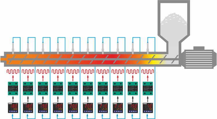
Измерители-регуляторы серии Eco-PID применяются в многозонных экструдерах, где количество зон нагрева экструдера определяет количество используемых регуляторов. Каждый терморегулятор автоматически поддерживает температуру только в своей зоне по ПИД (Pid) закону. При использовании измерителя регулятора в модификации без интерфейса RS-485, задание уставки температуры в зоне задается непосредственно на регуляторе. При использовании модификации с интерфейсом RS-485, есть возможность коррекции уставки с помощью программируемого логического контроллера(ПЛК) или ПК оператора.
Коммутация нагревательных элементов (ТЭНов) обычно осуществляется однофазными твердотельными реле с управляющим сигналом 3…32 В постоянного тока, устанавливаемых на радиаторы.
Для измерения температуры, используются термопары с байонетным присоединением типа J (ЖК), таких как TC-M06-L30-K1,5.J. В зависимости от типа экструдера длина погружения датчиков может варьироваться от 12мм до 30мм, а диаметр от 5 мм до 8 мм.
- Связь по RS-485 Modbus (RTU);
- внесены в реестр средств измерений Свидетельство №71565-18;
- 2-х строчный яркий дисплей;
- режим работы измерителя-регулятора: ON/OFF (двухпозиционный), ПИД-регулирование;
- компактный корпус ПИД-регулятора температуры: всего 48×48 мм;
- защита паролем от несанкционированного доступа к параметрам;
- настраиваемый аварийный выход, 7 режимов работы;
- низкое энергопотребление;
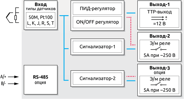
- универсальный вход для датчиков температуры:
- – термосопротивления: 50М, Pt100;
- – термопары: L, J, K, R, S, T.
| Параметр | Значение |
|---|---|
| Измерительный вход | термосопротивление (ТС): 50М, Pt100 термопара (ТП): L, J, K, R, S, T |
| Предел приведенной к диапазону измерения погрешности для измерения без десятичной точки | ±0,25% |
| Предел абсолютной погрешности для измерения с десятичной точкой | ТС: ±2,1 °C ТП: ±3,1 °C |
| Компенсация | ТС (сопротивления линии): до 10 Ом ТП (температура холодного спая): автоматическая |
| Период опроса | 100 мс |
| Метод регулирования | ON/OFF (двухпозиционный), П, ПИ, ПД, ПИД |
| Управляющий выход | э/м реле (5 А при ∼250 В, активная нагрузка) или ТТР выход — импульсный выход для управления внешним твердотельным реле (макс. 10 мА, =12 В |
| Аварийный выход | э/м реле (5 А при ∼250 В, активная нагрузка) |
| Напряжение питания | ~230 В (±15%), 50/60 Гц |
| Потребляемая мощность | 2 ВА |
| Окружающая среда | рабочая температура: (0…+50) °C температура хранения: (-40…+85) °C относительная влажность: (0…90)% (без образования конденсата) |
| Степень защиты | IP 65 (со стороны лицевой панели) IP 20 (со стороны клеммных колодок) |
| Индикация | верх: красный 3-х разрядный LED индикатор низ: оранжевый 4-х разрядный LED индикатор |
| Габаритные размеры (ШхВхГ) | 48×48×86,52 мм |
PID TEMPERATURE CONTROL UNIT
Eco
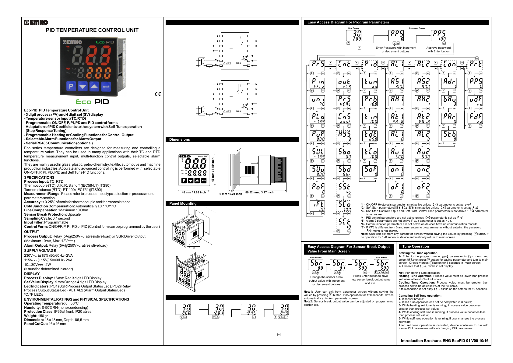
Eco PID, PID TemperatureControl Unit
— 3 digit process (PV) and 4 digit set (SV) display
— Temperaturesensor input (TC,RTD)
— Programmable ON/OFF, P, PI, PD and PID control forms
—Adaptationof PID Coefficientstothesystemwith Self-Tuneoperation
(Step Response Tuning)
— Programmable Heating or Cooling Functions for Control Output
— SelectableAlarm Funct ions for Alarm Output
— Serial RS485 Communication (optional)
Eco series temperature controllers are designed for measuring and controlling a
temperature value. They can be used in many applications with their TC and RTD
temperature measurement input, multi-function control outputs, selectable alarm
functions.
They are mainly used in glass, plastic, petro-chemistry, textile, automotive and machine
production industries. Accurate and advanced controlling is performed with selectable
ON-OFF,P,PI, PD, PID and Self Tune PID functions.
SPECIFICATIONS
Process Input: TC, RTD
Thermocouple (TC): J, K, R, S and T (IEC584.1)(ITS90)
Termoresistance(RTD): PT-100 (IEC751)(ITS90)
Measurement Range: Please refer to process input type selection in process menu
parameters section.
Accuracy: ± 0.25% of scale for thermocouple and thermoresistance
Cold Junction Compensation:Automatically ±0.1°C/1°C
Line Compensation: Maximum 10 Ohm
Sensor Break Protection: Upscale
Sampling Cycle: 0.1 second
Input Filter: Programmable
Control Form: ON/OFF, P, PI, PD or PID (Control form can be programmed by the user)
OUTPUT
Process Output: Relay (5A@250V at resistive load) or SSR Driver Output
(Maximum 10mA, Max. 12V )
Alarm Output: Relay (5A@250V at resistive load)
SUPPLYVOLTAGE
230V (±15%) 50/60Hz — 2VA
115V(±15%) 50/60Hz — 2VA
10…30V — 2W
(It must be determined in order)
DISPLAY
Process Display: 16 mm Red 3 digit LED Display
Set ValueDisplay: 9 mm Orange 4 digit LED Display
Led Indicators: PO1 (SSR Process Output Status Led), PO2 (Relay
Process Output Status Led),AL1, AL2 (Alarm Output Status Leds),
ºC, ºF LEDs
ENVIRONMENTALRATINGS and PHYSICALSPECIFICATIONS
Operating Temperature:0…50ºC
Humidity : 0-90%RH (none condensing)
Protection Class: IP65 at front, IP20 at rear
Weight: 150 gr.
Dimension: 48 x 48 mm, Depth: 86,5 mm
Panel CutOut: 46 x 46 mm
PID
Electrical Wirings
The Device with One Relay:
Serial Communication
(RS485, Modbus RTU)
PO1
(Process Output 1)
Supply
Voltage
Supply
Switch
1A T
Fuse
1
A+
2
3
SSR Output
12V
Max. 10mA
4
5
N
6
L
7
Eco
PID
8
NO
9
AL1 / PO2
(Alarm Output 1 or
C
5A@250V
Process Output 2)
10
11
12
Process
13
Input
TC
PT-100
14
B-
The Device with Two Relays:
NO
B-
1A T
Fuse
1
A+
2
5A@250V
SSR Output
12V
Max. 10mA
Eco
5A@250V
PID
3
4
5
N
6
L
7
Serial Communication
(RS485, Modbus RTU)
PO1
(Process Output 1)
Supply
Voltage
Supply
Switch
To reduce the effect of electrical noise on device, low voltage line (especially sensor
input cable) wiring must be separetely from high current and voltage line. If possible,
use shielded cable and shield must be connected to ground only one side.
Dimensions
Maximum 9 mm / 0.35 inch
PID
Eco
°C
°F
PO1
AL1
PO2
AL2
/
48 mm / 1.89 inch
48 mm / 1.89 inch
6 mm / 0.24 inch
Panel Mounting
1
°C
°F
Eco
PO1
AL1
PO2
AL2
/
3
2
4
5
6
°C
°F
Eco
PO1
AL1
PO2
AL2
/
Access and Change Set Values
Main Screen
°C
°F
PO1
AL1
PO2
/
AL2
Press increment or decrement
button to change process set value.
Temperature Set Value Parameter (Default: 200) MODBUS ADDRESS: 40000
a
Note: User can exit from set value section without saving the values by pressing button. If no
operation for 120 seconds, device automatically exits from Set Value section.
1- Before mounting the device in your panel,
make sure that the cutout is of the right size.
2- Check front panel gasket position.
3- Insert the device through the cutout. If the
mounting clamps are on the unit, put out them
before inserting the unit to the panel.
4- Insert the mounting clamps to the two of
designated holes that located four sides of
device.
5- Drag the mounting clamps in direction 5
until the device completely imm obile within the
panel.
6- In order to remove device push on the
mounting clamp as shown with arrow 6 and
pull back.
°C
°F
PO1
AL1
PO2
/ PO2
AL2
AL2 / PO2
8
(Alarm Output 2 or
Process Output 2)
NO
9
AL1
(Alarm Output 1)
C
10
11
12
Process
13
Input
TC
PT-100
14
80,52 mm / 3.17 inch
Main Screen
°C
°F
PO1
AL1
/
AL2
Press Enter button to sav e new
set value and return the main screen.
°C
°F
PO1
AL1
PO2
/
AL2
Easy Access Diagram For Program Parameters
Main Screen Password Screen
°C
°F
PO1
AL1
PO2
/
AL2
Press Program button
to access password screen.
°C
°F
PO1
AL1
PO2
/
AL2
°C
°F
PO1
AL1
PO2
/
AL2
°C
°F
PO1
AL1
PO2
/
AL2
°C
°F
PO1
AL1
PO2
/
AL2
°C
°F
PO1
AL1
PO2
/
AL2
°C
°F
PO1
AL1
PO2
/
AL2
°C
°F
PO1
AL1
PO2
/
AL2
°C
°F
PO1
AL1
PO2
/
AL2
°C
°F
PO1
AL1
PO2
/
AL2
Easy Access Diagram For Sensor Break Output
Value From Main Screen
Main Screen
°C
°F
PO1
AL1
PO2
/
AL2
Change the sensor break
output value with increment
or decrement buttons.
Note1: User can exit from parameter screen without saving the
values by pressing button. If no operation for 120 seconds, device
automatically exits from parameter screen.
Note2: Sensor break output value can be adjusted on programming
section too.
°C
°F
PO1
AL1
PO2
/
AL2
°C
°F
PO1
AL1
PO2
/
AL2
°C
°F
PO1
AL1
PO2
/
AL2
°C
°F
PO1
AL1
PO2
/
AL2
°C
*1
°F
PO1
AL1
PO2
/
AL2
°C
°F
PO1
AL1
PO2
/
AL2
°C
°F
PO1
AL1
PO2
/
AL2
°C
*2
°F
PO1
AL1
PO2
/
AL2
°C
*2,3
°F
PO1
AL1
PO2
/
AL2
°C
*2,3
°F
PO1
AL1
PO2
/
AL2
°C
°F
PO1
AL1
PO2
/
AL2
°C
°F
PO1
AL1
PO2
/ PO2
AL2
Press Enter button to save
new sensor break output value
Enter Password with increment
or decrement buttons.
°C
*4
°F
PO1
AL1
PO2
/
AL2
°C
°F
PO1
AL1
PO2
/
AL2
°C
°F
PO1
AL1
PO2
/
AL2
°C
°F
PO1
AL1
PO2
/
AL2
°C
°F
PO1
AL1
PO2
/
AL2
°C
°F
PO1
AL1
PO2
/
AL2
°C
°F
PO1
AL1
PO2
/
AL2
*1 — ON/OFF Hysteresis parameter is not active unless parameter is set as .
*2 — Soft Start parameters( , , ) is not active unless parameter is set as .
*3 — Soft Start Control Output and Soft Start Control Time parameters is not active if parameter
is set as .
*4 — PID control parameters are not active unless parameter is set as .
*5 — Alar m -2 parameters are not active if parameter is set as .
*6 — Communication parameters are not active on devices have no communication module.
*7 — If is different from 0 and user enters to program menu without entering the password
P
rot menu is not shown.
Note: User can exit from any parameter screen without saving the values by pressing button. If
no operation for 120 seconds, device automatically return to main screen.
Main Screen
°C
°F
PO1
AL1
/
AL2
and exit.
°C
°F
PO1
AL1
PO2
/
AL2
°C
°F
PO1
AL1
PO2
/
AL2
°C
°F
PO1
AL1
PO2
/
AL2
°C
°F
PO1
AL1
PO2
/
AL2
°C
°F
PO1
AL1
PO2
/
AL2
°C
°F
PO1
AL1
PO2
/
AL2
°C
°F
PO1
AL1
PO2
/
AL2
°C
°F
PO1
AL1
PO2
/
AL2
°C
°F
PO1
AL1
PO2
/PO2
AL2
Approve password
with Enter button
°C
*5
°F
PO1
AL1
PO2
/
AL2
°C
°F
PO1
AL1
PO2
/
AL2
°C
°F
PO1
AL1
PO2
/
AL2
°C
°F
PO1
AL1
PO2
/
AL2
°C
°F
PO1
AL1
PO2
/
AL2
*6
°C
°F
PO1
AL1
/
AL2
°C
°F
PO1
AL1
PO2
/
AL2
°C
°F
PO1
AL1
PO2
/
AL2
°C
°F
PO1
AL1
PO2
/
AL2
°C
°F
PO1
AL1
PO2
/
AL2
°C
°F
PO1
AL1
PO2
/
AL2
°C
°F
PO1
AL1
PO2
/
AL2
°C
°F
PO1
AL1
PO2
/
AL2
°C
°F
PO1
AL1
PO2
/
AL2
Tune Operation
Starting the Tune operation
1- Enter to the program menu parameter in menu and
select ,then press button for saving parameter and turn to main
screen. Or easily press button for 3 seconds in main screen.
2- Observe that blinks in set display
Not: For starting tune operation,
Heating Tune Operation: Process value must be lower than process
set value at least 5% of full scale.
Cooling Tune Operation: Process value must be greater than
process set value at least 5% of the full scale.
If this condition is not okay, blinks on the screen for 10 seconds.
Canceling Self Tune operation:
1- If sensor breaks;
2- If self tune operation can not be completed in 8 hours;
3- While heating self tune is running, if process value becomes
greater than process set value;
4- While cooling self tune is running, if process value becomes less
than process set value;
5- While self tune operation is running, if user changes the process
set value;
Then self tune operation is canceled, device continues to run with
former PID parameters without changing PID parameters.
Introduction Brochure. ENG EcoPID 01 V00 10/16
°C
*7
°F
PO1
AL1
PO2
/
AL2
°C
°F
PO1
AL1
PO2
/
AL2
°C
°F
PO1
AL1
PO2
/
AL2
°C
°F
PO1
AL1
PO2
/
AL2
: Process Menu Parameters
: Process input type selection; (Default: ) Modbus Address: 40004
: J type (Fe,Cu,Ni) Thermocouple , -199ºC,900ºC ; -199ºF,999ºF
: K type (Ni,Cr,Ni) T herm ocouple , -199ºC,999ºC ; -199ºF,999ºF
: R type (Pt13%RhPt) Thermocouple , 0ºC,999ºC ; 32ºF,999ºF
: S type (Pt10%RhPt) Thermocouple , 0ºC,999ºC ; 32ºF,999ºF
: T type (Cu,Cu,Ni) Thermocouple , -199ºC,400ºC ; -199ºF,752ºF
: Pt-100 , -199ºC,650ºC ; -199ºF,999ºF
: Unit Selection. or can be chosen. (Default: ) Modbus Address: 40005
: Operation Scale minimum (Low Limit) value. It changes according to the process
input type and scale. (Default: -199) Modbus Address: 40006
: Operation Scale maximum (High Limit) value. It changes according to the
process input type and scale. (Default: 900) Modbus Address: 40007
: Process Set value Low Limit. Minimum set value is defined with this parameter.
It changes according to the process input type and scale.(Default: -199) Modbus
Address: 40008
: Process Set value High Limit. Maximum set value is defined with this parameter.
It changes according to the process input type and scale. (Default: 900) Modbus
Address: 40009
: Display offset for process value. It can be adjusted from -10% of scale to 10% of
scale. It is added to the process displa y value. (Default: 0) Modbus Address: 40010
: Define filter time(sec) for displayed value. (Default: 1.0) Modbus Address: 40011
: Control Menu Parameters
: This parameter determines, which output will be Process control output. If is
chosen, process output is relay output, if is chosen, process output is SSR output.
(Default: ) Modbus Address: 40015
: Process Type Selection. It can be (Heating) or (Cooling).(Default: )
Modbus Address: 40016
: Process Control Type Selection. It can be or . (Default: ) Modbus
Address: 40017
: Hysteresis value. It can be adjusted from %0 to %50 of the Scale ( — ).
If = , then this parameter can be seen. (Default: 3) Modbus Address: 40018
: Sensor Break Output Value. It can be adjusted from %0 to %100. (Default: 0.0)
Modbus Address: 40019
: The choice of displayed text on process value display when sensor is broken.
It can be or . (Default: ) Modbus Address: 40020
: Soft Start Set value. Device operates in Soft Start mode, until the temperature
reaches Soft Start set value. If is selected, Soft Start mode is disable d. (Default: )
Modbus Address: 40021
: Soft Start Control Output. This parameter determines soft start mode control
output percentage. It can be adjusted from %10 to %90. (Default: 10.0) Modbus
Address: 40022
: Soft Start Control Time. This parameter determines soft start mode control time.
(Default: 1.0) Modbus Address: 40023
: PID Menu Parameters
PID menu parameters can be seen only if parameter is .
: If tune parameter is set to , device start to calculate PID parameters
automatically. (Default: ) Modbus Address: 40027
: Proportional band. It can be adjusted from %1.0 to %100.0. (Default: 10.0)
Modbus Address: 40028
: Integral Time. It can be adjusted from 0 to 3600 second. (Default: 100) Modbus
Address: 40029
: Derivative Time. It can be adjusted from 0.0 to 999.9 second. (Default: 25.0)
Modbus Address: 40030
: Output Control Period. It can be adjusted from 0.5 to 150 second. (Default: 10.0)
Modbus Address: 40031
: Set value offset. (Set + ) is used as set value in PID calculations. This
parameter is used for shifting the proportional band. It can be adjusted from (- /2) to
( /2). (Default: 0) Modbus Address: 40032
: Alarm-1 Menu Parameters
: Alarm-1 set value. (Default: 300) Modbus Address: 40036
: Alarm-1 hysteresis value. It can be adjusted from %0 to %50 of the scale
( — ). (Default: 0) Modbus Address: 40037
: Alarm-1 type selection. (Default: ) Modbus Address: 40038
: Alarm-1 set low limit parameter. It can be adjusted from operation scale minimum
to alarm-1 set high limit. (Default: 0) Modbus Address: 40039
: Alarm-1 set high limit parameter. It can be adjusted from alarm-1 set low limit to
operation scale minimum. (Default: 500) Modbus Address: 40040
: Alarm-1 on Delay Time. It can be adjusted from 0 to 9999 seconds. (Default: 0)
Modbus Address: 40041
: Alarm-1 off Delay Time. It can be adjusted from 0 to 9998 seconds. If it is higher
than 9998, is seen on the screen and alarm latching output is selected. In alarm
latching output mode in order to make passive alarm outputs, press enter button at
main screen. (Default: 0) Modbus Address: 40042
: Alarm-2 Menu Parameters (Only for devices with two relays)
Alarm-2 menu parameters can be seen only if parameter is .
: Alarm-2 set value. (Default: 400) Modbus Address: 40046
: Alarm-2 hysteresis value. It can be adjusted from %0 to %50 of the Scale
( — ). (Default: 0) Modbus Address: 40047
: Alarm-2 type selection. (Default: ) Modbus Address: 40048
: Alarm-2 set low limit parameter. It can be adjusted from operation scale minimum
to alarm-2 set high limit. (Default: 0) Modbus Address: 40049
: Alarm-2 set high limit parameter. It can be adjusted from alarm-2 set low limit to
operation scale maximum. (Default: 500) Modbus Address: 40050
: Alarm-2 on delay time. It can be adjusted from 0 to 9999 seconds. (Default: 0)
Modbus Address: 40051
: Alarm-2 off delay tim e. It can be adjusted from 0 to 9998 seconds. If it is higher
than 9998, is seen on the screen and Alarm Latching Output is selected. In
alarm latching output mode in order to make passive alarm outputs, press enter
button at main screen. (Default: 0) Modbus Address: 40052
: Communication Parameters (Only for devices with RS-485 com.)
: Communication accessing address of device. (Default: 1) Modbus
Address: 40056
: Communication Baud Rate. (Default: 3) Modbus Address: 40057
: 1200 Baud Rate.
: 2400 Baud Rate.
: 4800 Baud Rate.
: 9600 Baud Rate.
: 19200 Baud Rate.
: 38400 Baud Rate.
: Parity Selection for Communication. (Default: 0) Modbus Address: 40058
: No Parity.
: Odd Parity.
: Even Parity.
: Stop Bit Selection for Communication. (Default: 0) Modbus Address: 40059
: 1 Stop Bit.
: 2 Stop Bit.
: Protecion Menu Parameters
: Password for accessing to the programming section. It can be adjusted from 0 to
9999. If is 0, password screen is not seen. If is different from 0 and user
enters to the menu pages without entering the password, all the menus can be
observed except protection menu . But device does not allow to do any changes
in parameters. (Default: 0) Modbus Address: 40063
: User default parameters. This parameter is used for saving all parameters to
restore later or restore all parameters saved before. If is chosen, all parameters
saved before are restored. If is chosen, all parameters saved to restore later. If
is chosen, nothing is changed. (Default: ) Modbus Address: 40064
: This parameter is used for restore factory defaults. If is chosen, factory
defaults parameters restored. If is chosen, nothing is changed. (Default: )
Modbus Address: 40065
Remove all input/output connections on terminals before restoring
parameters to user/factory defaults.
Modbus Addresses of Device Operation Info. (Read Input Register)
Modbus Address: 30000
Modbus Address: 30001
Modbus Address: 30002
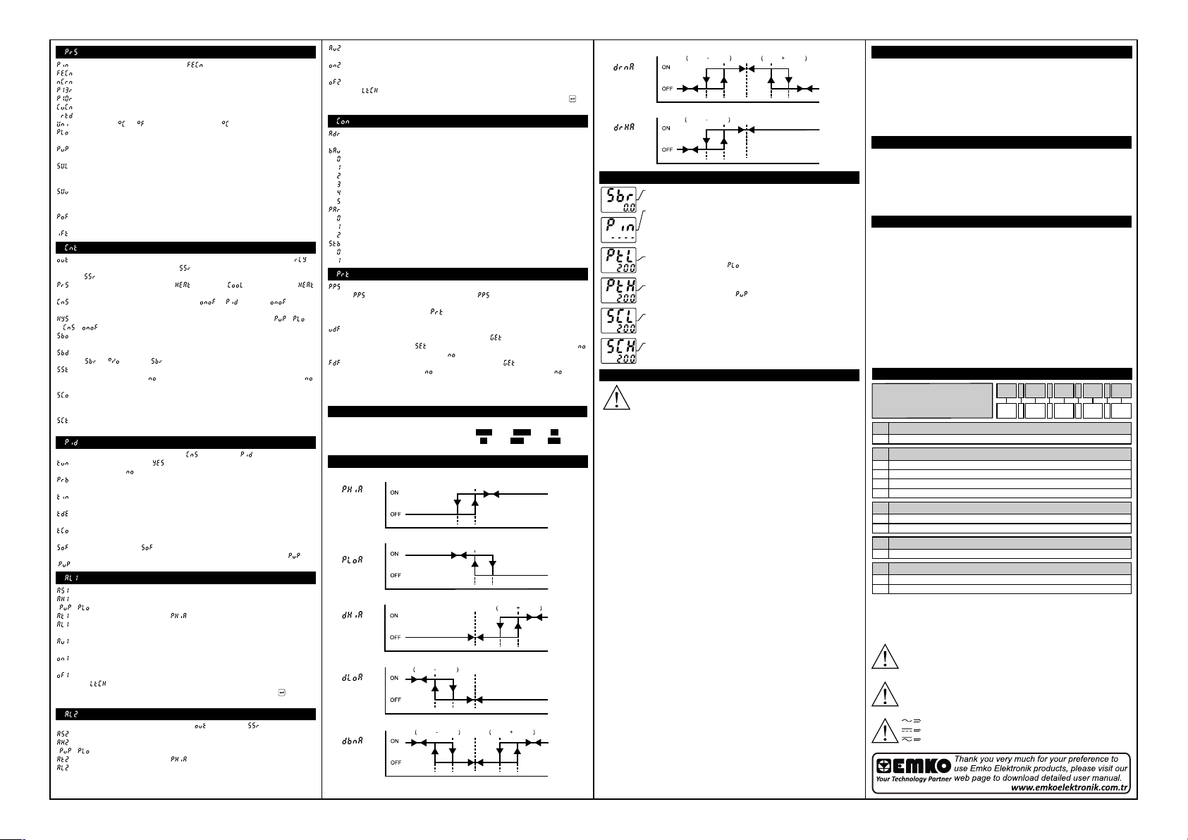
Alarm Types
Process High
Alarm
Process Low
Alarm
Deviation High
Alarm
Deviation Low
Alarm
Deviation Band
Alarm
Displayed Temperature Value
Status of LEDs: bit.1 ALR1, bit.2 ALR2, bit.9 °C
Status of Device: bit.0 Sensor Break Status
Alarm
Output
Alarm
Output
Alarm
Output
Alarm
Output
Alarm
Output
bit.10 °F, bit.11 PO2, bit.12 PO1
Alarm
Hysteresis
Process
Alarm
Set
Set
Alarm
Hysteresis
Process
Alarm
Set
Set
Alarm
Hysteresis
Alarm
Alarm
Process
Process
Process
Set
Set
Set
Set
Set
Alarm
Hysteresis
Process
Set
Process
Set
Alarm
Hysteresis
Alarm
Hysteresis
Process Value
Process Value
Alarm
Set
Process Value
Process Value
Alarm
Set
Process Value
Alarm
Deviation Range
Alarm
Deviation Range
High Alarm
Error Messages
°C
°F
PO1
AL1
PO2
/
AL2
°C
°F
PO1
AL1
PO2
/
AL2
°C
°F
PO1
AL1
PO2
/
AL2
°C
°F
PO1
AL1
PO2
/
AL2
°C
°F
PO1
AL1
PO2
/
AL2
°C
°F
PO1
AL1
PO2
/
AL2
Output
Process
Alarm
Set
Set
Alarm
Hysteresis
Alarm
Output
Process
Alarm
Set
Set
Alarm
Hysteresis
1-Sensor failur e in analog inputs. Sensor connection is wrong or there
is no sensor connection.
a
2-If programming section entering password is different from “0” and
user accesses to the parameter by enter button without entering the
password and wants to change a parameter, the warning m essage is
shown on the bottom display as shown on the left. Device does not
allow to do any changes without entering the password correctly.
a
3-If value that is read from the analog input is lower than process set
low limit parameter va lue ( ), value on the top display starts to blink
as shown on the picture.
a
4-If value that is read from the analog input is higher than process set
high limit parameter value ( ), value on the top display starts to
blink as shown on the picture.
a
5-If value that is read from the analog input is lower than sensor scale
low limit, value on the top display starts to blink as shown on the
picture.
a
6-If value that is read from the analog input is higher than sensor scale
high limit, value on the top display starts to blink as shown on the
picture.
Process
Process
Process
Alarm
Set
Alarm
Hysteresis
Set
Process Value
Process Value
Set
Set
Installation
Before beginning installation of this product, please
read the instruction manual and warnings below
carefully.
In package,
-One piece unit
-Two pieces mounting clamp
-One piece instruction manual
A visual inspection of this product for possible damage occured
during shipment is recommended before installation. It is your
responsibility to ensure that qualified mechanical and electrical
technicians install this product.
If there is danger of serious accident resulting from a failure or defect
in this unit, power off the system and the electrical connection of the
device from the system.
The unit is normally supplied without a power switch or a fuse. Use
power switch and fuse as required.
Be sure to use the rated power supply voltage to protect the unit
against damage and to prev ent failure.
Keep the power off until all of the wiring is completed so that electric
shock and trouble with the unit can be prevented.
Never attempt to disassemble, modify or repair this unit. Tampering
with the unit may results in malfunction, electric shock or fire.
Do not use the unit in combustible or explosive gaseous
atmospheres. During the equipment is putted in hole on the metal
panel while mechanical installation some metal burrs can cause
injury on hands, you must be careful.
Montage of the product on a system must be done with it’s mounting
clamp. Do not do the montage of the device with inappropriate
mounting clamp. Be sure that device will not fall while doing the
montage.
It is your responsibility if this equipment is used in a manner not
specified in this instruction manual .
Warranty
EMKO Elektronik warrants that the equipment delivered is free from
defects in material and workmanship. This warranty is provided for a
period of two years. The warranty period starts from the delivery
date.
This warranty is in force if duty and responsibilities which are
determined in warranty document and instruction manual performs
by the customer completely.
Maintenance
Repairs should only be performed by trained and specialized
personnel. Cut power to the device before accessing internal parts.
Do not clean the case with hydrocarbon-based solvents (Petrol,
Trichlorethylene etc.). Use of these solvents can reduce the
mechanical reliability of the device. Use a cloth dampened in ethyl
alcohol or water to clean the external plastic case.
Other Informations
Manufacturer Information:
Emko Elektronik Sanayi ve Ticaret A.Ş.
Demirtaş Organize Sanayi Bölgesi Karanfil Sk. No:6 16369
BURSA/TURKEY
Phone: +90 224 261 1900
Fax: +90 224 261 1912
a
Repair and Maintenance Service Information:
Emko Elektronik Sanayi ve Ticaret A.Ş.
Demirtaş Organize Sanayi Bölgesi Karanfil Sk. No:6 16369
BURSA/TURKEY
Phone: +90 224 261 1900
Fax : +90 224 261 1912
Ordering Information
A
Eco PID ( 48×48 DIN 1/16 )
Dimension
A
48×48 DIN 1/16
4
Supply VoltageB
115V (±%15) 50/60Hz
3
230V (±%15) 50/60Hz
5
10…30V
6
9
Customer
Outputs-1
C
1 x Relay Output (5A@250V at Resistive Load) (NO,C)
1R
2 x Relay Output (5A@250V at Resistive Load) (NO,NO,C)
2R
Outputs-2
D
S SSR Driver Output (Max. 10mA, Max. 12V)
Communication
E
None
0
485
RS-485 Communication
Before commissioning the device, parameters must be set in
accordance with desired use. Incomplete or incorrect configuration
can cause dangerous stiuations.
Because of lim ited mechanical life of relay output contact, SSR
output is recommended which the device use PID control algoritm.
The device with ON/OFF control algor itm, hysteresis parameter must
be set a suitable value for your system, to avoid too much relay
switching.
Vac,
Vdc,
Vdc or Vac can be applied
B.C.D
4 .
E
S .
3
2
1
4
5
6
Eco PID+, PID Temperature Control Un�t
— 4 d�g�t process (PV) and 4 d�g�t set (SV) d�splay
— Temperature sensor �nput (TC,RTD)— Programmable ON/OFF, P, PI, PD and PID control forms
— Adaptat�on of PID Coeff�c�ents to the system w�th Self-Tune and Auto-Tune
— Programmable Heat�ng or Cool�ng Funct�ons for Control Output
— Selectable Alarm Funct�ons for Alarm Output
— Ser�al RS485 Commun�cat�on (opt�onal)
Introduct�on Brochure. ENG EcoPID+ 01 V00 03/22
Easy Access D�agram For Program ParametersPanel Mount�ngEnter Password w�th �ncrementor decrement buttons.Approve passwordw�th Enter buttonPassword Screen
Eco ser�es temperature controllers are des�gned for measur�ng and controll�ng a
temperature value. They can be used �n many appl�cat�ons w�th the�r TC and RTD
temperature measurement �nput, mult�-funct�on control outputs, selectable alarm
funct�ons.
They are ma�nly used �n glass, plast�c, petro-chem�stry, text�le, automot�ve and mach�ne
product�on �ndustr�es. Accurate and advanced controll�ng �s performed w�th selectable
ON-OFF, P, PI, PD, PID and Self Tune/Auto Tune PID funct�ons.SPECIFICATIONSProcess Input: Thermocouple (TC): J, K, R, S, T and L (IEC584.1)(ITS90)
Thermores�stance (RTD): Cu-50 and PT-100 (IEC751)(ITS90)
Measurement Range: Please refer to process �nput type select�on �n process menu
parameters sect�on.Accuracy:
Thermocouple (TC):( ± 0.25% of full scale or ± 3ºC, wh�ch one �s greater) ±1 d�g�t max.
Thermores�stance (RTD):( ± 0.25% of full scale or ± 2ºC, wh�ch one �s greater) ±1 d�g�t
max.
Cold Junct�on Compensat�on: Automat�cally ±0.1°C/1°C
L�ne Compensat�on: Max�mum 10 Ohm
Sensor Break Protect�on: UpscaleSampl�ng Cycle: 0.1 secondInput F�lter: ProgrammableControl Form: ON/OFF, P, PI, PD or PID (Control form can be programmed by the user)OUTPUT
Process Output: Relay (5A@250VV at res�st�ve load) or SSR Dr�ver Output
(Max�mum 10mA, Max. 12VZ )
Alarm Output: Relay (5A@250VV at res�st�ve load)
SUPPLY VOLTAGE (It must be determ�ned �n order)
230VV (±15%) 50/60Hz — 4VA115VV (±15%) 50/60Hz — 4VA100-240VV 50/60Hz — 4VA24VV(±%15) 50/60Hz — 4VA24VW (±%15) 50/60Hz — 4VA10…30VZ — 4W DISPLAY
Process D�splay: 16 mm Red 4 d�g�t LED D�splay
Set Value D�splay: 9 mm Orange 4 d�g�t LED D�splay
Led Ind�cators: PO1 (SSR Process Output Status Led), PO2 (Relay Process Output Status Led), AL1, AL2 (Alarm Output Status Leds),ºC, ºF LEDs
ENVIRONMENTAL RATINGS and PHYSICAL SPECIFICATIONS
Operat�ng Temperature: 0…50ºC
Hum�d�ty : 0-90%RH (none condens�ng)
Mechan�cal Impacts: 1Joule (IK06)
Protect�on Class: NEMA 4X (IP65 at front, IP20 at rear)
We�ght: 150 gr.
D�mens�on: 48 x 48 mm, Depth: 86,5 mm
Panel CutOut: 46 x 46 mm
*1 — ON/OFF Hysteres�s parameter �s not act�ve unless parameter �s set as .
*2 — Soft Start parameters( , , ) �s not act�ve unless parameter �s set as .
*3 — Soft Start Control Output and Soft Start Control T�me parameters �s not act�ve �f parameter
�s set as .
*4 — PID control parameters are not act�ve unless parameter �s set as .
*5 — Alarm-2 parameters are not act�ve �f parameter �s set as .
*6 — Commun�cat�on parameters are not act�ve on dev�ces have no commun�cat�on module.
*7 — If �s d�fferent from 0 and user enters to program menu w�thout enter�ng the password
P
rot menu �s not shown.
Note: User can ex�t from any parameter screen w�thout sav�ng the values by press�ng button. If
no operat�on for 120 seconds, dev�ce automat�cally return to ma�n screen.
Easy Access D�agram For Sensor Break OutputValue From Ma�n ScreenChange the sensor breakoutput value w�th �ncrementor decrement buttons.Press Enter button to savenew sensor break output valueand ex�t.Ma�n Screen Ma�n Screen
Note1: User can ex�t from parameter screen w�thout sav�ng the
values by press�ng button. If no operat�on for 120 seconds, dev�ce
automat�cally ex�ts from parameter screen.Note2: Sensor break output value can be adjusted on programm�ng sect�on too.Tune Operat�onStart�ng the Tune operat�on
1- Enter to the parameter �n menu and select
or ,then press button for sav�ng parameter and turn to ma�n
screen. Or eas�ly press button for 3 seconds* �n ma�n screen.
2- Observe that bl�nks �n set d�splay.
*Only Self Tune can be started by th�s way.Cancel�ng Tune operat�on:1- If sensor breaks;
2- If tune operat�on can not be completed �n 8 hours;
3- Wh�le heat�ng self tune �s runn�ng, �f process value becomes
greater than process set value;
4- Wh�le cool�ng self tune �s runn�ng, �f process value becomes less
than process set value;
5- Wh�le tune operat�on �s runn�ng, �f user changes the process set
value;
6- Wh�le tune operat�on �s runn�ng, �f user changes the
parameter �n menu;
Then tune operat�on �s canceled, dev�ce cont�nues to run w�th former
PID parameters w�thout chang�ng PID parameters.
PID TEMPERATURE CONTROL UNIT
PID+
Eco
D�mens�ons48 mm / 1.89 �nch48 mm / 1.89 �nch6 mm / 0.24 �nch80,52 mm / 3.17 �nchMax�mum 9 mm / 0.35 �nch
1- Before mount�ng the dev�ce �n your panel,
make sure that the cutout �s of the r�ght s�ze.
2- Check front panel gasket pos�t�on.3- Insert the dev�ce through the cutout. If the mount�ng clamps are on the un�t, put out them before �nsert�ng the un�t to the panel.
4- Insert the mount�ng clamps to the two of
des�gnated holes that located four s�des of dev�ce.
5- Drag the mount�ng clamps �n d�rect�on 5
unt�l the dev�ce completely �mmob�le w�th�n the
panel.6- In order to remove dev�ce push on the
mount�ng clamp as shown w�th arrow 6 and
pull back. Access and Change Set Values
Press �ncrement or decrement
button to change process set value.
Press Enter button to save new
set value and return the ma�n screen.
Ma�n ScreenMa�n ScreenTemperature Set Value Parameter (Default: 200) MODBUS ADDRESS: 40000
a
Note-1: User can ex�t from set value sect�on w�thout sav�ng the values by press�ng button. If no
operat�on for 120 seconds, dev�ce automat�cally ex�ts from Set Value sect�on.
Note-2: Set value can be adjusted between Set Value Low and H�gh L�m�t ( — ).
Press Program buttonto access password screen.Electr�cal W�r�ngs
To reduce the effect of electr�cal no�se on dev�ce, low voltage l�ne (espec�ally sensor
�nput cable) w�r�ng must be separetely from h�gh current and voltage l�ne. If poss�ble,
use sh�elded cable and sh�eld must be connected to ground only one s�de.
c
Note-1: External Fuse �s recommended.
Note-2: Stranded cable cross sect�on: 1,5mm², Sol�d cable cross-sect�on: 2,5mm²
The str�pp�ng length �s 7mm to 9mm.
Note-3: Supply cables must comply w�th the requ�rements of IEC 60277 or IEC 60245.
It �s adv�sed to use a two-pole supply sw�tch, des�gnated for th�s dev�ce, w�th open/
closed pos�t�ons marked, �n order to cut the power. It must be placed on the supply
�nput of the dev�ce at a place where the user can eas�ly reach.
V External fuse must be on phase connect�on of the supply �nput.
Z External fuse must be on (+) l�ne connect�on of the supply �nput.
Make sure that the power supply voltage range �s su�table for the dev�ce.
Sw�tch on the power supply only after all the electr�cal connect�ons are �n place.
1
2
3
4
5
6
7
8
9
10
11
12
13
14
PO1
(Process Output 1)
SSR Output
12V
Max. 10mA
C
NO
NO
AL1
(Alarm Output 1)
AL2 / PO2
(Alarm Output 2 or
Process Output 2)
ProcessInput5A@250V5A@250VSer�al Commun�cat�on
(RS485, Modbus RTU)
A+
B-
PID+
EcoPT-100
TC
SupplySw�tch
L
N
SupplyVoltage1A T
Fuse
NOTE-1AL1 / PO2
(Alarm Output 1 or
Process Output 2)
ProcessInput
8
9
10
11
C
NO
5A@250V
12
13
14
PT-100
TC
The Dev�ce w�th Two RelaysThe Dev�ce w�th One RelayÇalışma Ekranı
*1
*5
*2
*4
*2,3
*2,3
*7*6
ECO PID
PID Temperature Control Unit
High Resolution Sensitive PID control
TC (J,K,R,S,T Input Types) and RTD inputs
selectable by parameter
Low Power Consumption, Energy saving and
Environmentally Friendly with 2VA
Saving and Recovery of user parameters
Return to Factory Settings
3 Digits Process (PV) and 4 Digits Set (SV) display
Programmable ON-OFF, P, PI, PD, PID control forms
Adaptation of PID Coefficients to the system
with Self-Tune operation (Step ResponseTuning) and
Auto-Tune (limitcycling-tuning)
Selectable heating and cooling function
RS-485 Modbus (RTU) communication (Optional)
Share :
Цифровой измеритель-регулятор температуры Eco PID
Вход: (ТС): 50М, Pt100; (ТП): L, J, K, R, S, T Выход: э/м реле (5 А при ∼250 В, активная нагрузка) или ТТР выход — импульсный выход для управления внешним твердотельным реле (макс. 10 мА, =12 В Регулирование: ON/OFF (двухпозиционный), П, ПИ, ПД, ПИД Настраиваемый аварийный выход, 7 режимов работы Защита паролем от несанкционированного доступа к параметрам
ПИД-регулятор для ОЕМ-применений ESM-xx20
Вход: ТП: L, J, K, R, S, T; ТС: 50М, Pt100 Выход: реле (5А при ~250 В, активная нагрузка НО+НЗ) импульсный выход для твердотельного реле (20 мА, =12 В) Регулирование: ON/OFF (двухпозиционный), П, ПИ, ПД, ПИД (настраивается пользователем) 4 типа корпуса 48×48, 96×48, 72×72, 96×96 мм Два настраиваемых аварийных выхода: 7 режимов работы
ПИД-регулятор с 2-мя уставками Eco HR
Вход:(ТС): 50М, Pt100; (ТП): L, J, K, R, S, T Выход: э/м реле (5 А при ∼250 В, активная нагрузка) или ТТР выход — импульсный выход для управления внешним твердотельным реле (максимум 10 мА, =12 В) Регулирование: ON/OFF (двухпозиционный), ПИД-регулирование Настраиваемый аварийный выход, 7 режимов работы Защита паролем от несанкционированного доступа к параметрам
ПИД-регулятор с универсальным входом ESM-xx30
Вход: ТС: Pt100, 50М; TП: J, K, R, S, T, B, E, N, L ток: 0…20 мА, 4…20 мА напряжение: 0…50 мВ, 0…5 В, 0…10 В Выход: 2× реле (5 А при ~ 250 B, активная нагрузка) SSR — импульсный выход под твердотельное реле Регулирование: ON/OFF (двухпозиционный), П, ПИ, ПД, ПИД (настраивается пользователем) Коррекция входного сигнала датчика
ПИД-регулятор с выходом 4…20 мА ESM-4435
Вход: ТС: 50М, Pt100; TП: L, J, K, R, S, T, B, E, N ток: 0…20 мА, 4…20 мА напряжение: 0…50 мВ, 0…5 В, 0…10 В Выход: ток 0(4)…20 мА (максимальная нагрузка 600 Ом) реле (5 А при ~250 В, активная нагрузка НО+НЗ) Регулирование: ПИД (пропорционально-интегрально-дифференциальный) Коррекция и фильтрация входного сигнала датчика
Универсальный программируемый ПИД-регулятор ESM-xx50
Вход: термосопротивление (ТС): 50М, Pt100 термопара (ТП): L, J, K, R, S, T, B, E, N ток: 0…20 мА, 4…20 мА напряжение: 0…50 мВ, 0…5 В, 0…10 В Выход: реле (5 А при ~250 В, активная нагрузка) Два слота расширения для подключения модулей вывода Настраиваемый закон регулирования (ON/OFF, П, ПИ, ПД, ПИД)
Измеритель-регулятор с ручным заданием ESD-9950-N
Вход (универсальный): ТС: 50M, Pt100; ТП: L, J, K, R, S, T Выход: реле (10 А при ~ 250 B, активная нагрузка НО+НЗ) Регулирование: ON/OFF (двухпозиционный) Режим работы регулятора – нагреватель