

EV2000 Series Universal Variable Speed Drive
User Manual
Version: 2.0
Revision date: May 17, 2005
BOM: 31011071
Emerson Network Power provides customers with technical support. Users may
contact the nearest Emerson local sales office or service center.
Copyright © 2005 by Emerson Network Power Co., Ltd.
All rights reserved. The contents in this document are subject to change without
notice.
Emerson Network Power Co., Ltd.
Address: No.1 Kefa Rd., Science & Industry Park, Nanshan District 518057,
Shenzhen China
Homepage: www.emersonnetworkpower.com.cn
Customer Service Hotline: 800-820-6510, (86) 21-23017141,(86) 755-86011668
E-mail: support@emersonnetwork.com.cn


Contents
Preface………………………………………………………………………………………………………………………………………………………….. 1
Unpacking Inspection………………………………………………………………………………………………………………………………… 1
Model designation rules …………………………………………………………………………………………………………………………….. 1
Chapter 1 Safety……………………………………………………………………………………………………………………………………………2
1.1 Safety ……………………………………………………………………………………………………………………………………………… 2
1.2 Notes for Installations ………………………………………………………………………………………………………………………… 2
1.3 Notes for Using EV2000 …………………………………………………………………………………………………………………….. 2
1.3.1 About Motor and Load …………………………………………………………………………………………………………………. 2
1.3.2 About Variable Speed Drive………………………………………………………………………………………………………….. 3
1.4 Disposing Unwanted Drive ………………………………………………………………………………………………………………….4
Chapter 2 Product Introduction……………………………………………………………………………………………………………………….. 5
2.1 Specifications ……………………………………………………………………………………………………………………………………5
2.2 Product Series ………………………………………………………………………………………………………………………………….. 7
2.2.1 Ratings………………………………………………………………………………………………………………………………………. 7
2.2.2 Parts of Variable Speed Drive……………………………………………………………………………………………………….. 8
2.2.3 Outline and Gross Weight…………………………………………………………………………………………………………….. 8
2.3 Optional Parts…………………………………………………………………………………………………………………………………. 12
2.3.1 LCD Operational Panel ………………………………………………………………………………………………………………. 12
2.3.2 Braking Kits………………………………………………………………………………………………………………………………. 12
2.3.3 Communication Parts…………………………………………………………………………………………………………………. 14
Chapter 3 Installation and Wiring…………………………………………………………………………………………………………………… 15
3.1 Installation Environment …………………………………………………………………………………………………………………… 15
3.2 Removing and Mounting of Parts ……………………………………………………………………………………………………….15
3.2.1 Removing and Installation of Operation Panel ……………………………………………………………………………….. 15
3.2.2 Removing and Mounting of Cover………………………………………………………………………………………………… 16
3.3 Wire Connections of Drive………………………………………………………………………………………………………………… 17
3.3.1 Wire Connections of Main Terminals ……………………………………………………………………………………………. 17
3.3.2 Wiring of Control Circuit ……………………………………………………………………………………………………………… 22
3.4 Installation Methods Compliant With EMC Requirements ……………………………………………………………………… 31
3.4.1 Noise Suppressing…………………………………………………………………………………………………………………….. 31
3.4.2 Field Wire Connections………………………………………………………………………………………………………………. 32
3.4.3 Earthing …………………………………………………………………………………………………………………………………… 33
3.4.4 Installation Requirements of Relay, Contactor and Electro-magnetic Braking Kit ………………………………… 34
3.4.5 Leakage Current ……………………………………………………………………………………………………………………….. 34
3.4.6 Correct EMC Installation …………………………………………………………………………………………………………….. 34
3.4.7 Application of Power Line Filter……………………………………………………………………………………………………. 35
3.4.8 EMI of The Drive ……………………………………………………………………………………………………………………….. 36
Chapter 4 Operation Instructions…………………………………………………………………………………………………………………… 37
4.1 Notice ……………………………………………………………………………………………………………………………………………. 37
4.1.1 The Drive’s Control Modes………………………………………………………………………………………………………….. 37
4.1.2 Reference Selector ……………………………………………………………………………………………………………………. 37
4.1.3 Operating Status ……………………………………………………………………………………………………………………….. 37
4.1.4 Operating Modes ………………………………………………………………………………………………………………………. 37
4.2 Operating Instructions ……………………………………………………………………………………………………………………… 38
4.2.1 Using Operation Panel……………………………………………………………………………………………………………….. 38
4.2.2 Function of Keys ……………………………………………………………………………………………………………………….. 39
4.2.3 Function Descriptions of LED and Indicators …………………………………………………………………………………. 39

4.2.4 Display of the Drive……………………………………………………………………………………………………………………. 40
4.2.5 Panel Operation ………………………………………………………………………………………………………………………… 40
4.3 Start-up………………………………………………………………………………………………………………………………………….. 41
4.3.1 Checking before Start-up ……………………………………………………………………………………………………………. 41
4.3.2 Start up the Drive for the First Time ……………………………………………………………………………………………… 42
Chapter 5 Parameter Introductions………………………………………………………………………………………………………………… 43
5.1 Basic Operating Parameters(Group F0) ………………………………………………………………………………………………… 43
5.2 Parameters of Reference Frequency (Group F1) …………………………………………………………………………………. 46
5.3 Starting and Braking Parameters (Group F2) ………………………………………………………………………………………. 47
5.4 Auxiliary Operating Parameters (Group F3) …………………………………………………………………………………………49
5.5 PLC Operating Parameters(Group F4)……………………………………………………………………………………………………. 52
5.6 Close-loop Control Parameters(Group F5)………………………………………………………………………………………………….. 55
5.7 Traverse Operating Parameters (Group F6)………………………………………………………………………………………… 58
5.8 Function of Terminals(Group F7)……………………………………………………………………………………………………….. 60
5.9 Display (Group F8) ………………………………………………………………………………………………………………………….. 69
5.10 Enhanced Functions(Group F9) ……………………………………………………………………………………………………….70
5.11 Reserved (Group FA) …………………………………………………………………………………………………………………….. 76
5.12 Communication Parameters (Group FF)…………………………………………………………………………………………………. 76
5.13 Motor Parameters (Group FH)…………………………………………………………………………………………………………. 77
5.14 Protective Function (Group FL) ………………………………………………………………………………………………………..78
5.15 Drive Parameters (Group Fn) ………………………………………………………………………………………………………….. 81
5.16 Protection of Parameters (FP) …………………………………………………………………………………………………………. 81
Chapter 6 Troubleshooting …………………………………………………………………………………………………………………………… 83
Chapter 7 Maintenance ………………………………………………………………………………………………………………………………..88
7.1 Daily Maintenance…………………………………………………………………………………………………………………………… 88
7.2 Periodical Maintenance ……………………………………………………………………………………………………………………. 88
7.3 Replacing Wearing Parts………………………………………………………………………………………………………………….. 89
7.4 Storage………………………………………………………………………………………………………………………………………….. 89
7.5 Warranty………………………………………………………………………………………………………………………………………… 89
Appendix 1 Parameters ……………………………………………………………………………………………………………………………….. 90
Appendix 2 Accessories …………………………………………………………………………………………………………………………….. 108
Appendix 3 Communication Protocol……………………………………………………………………………………………………………. 111
1 Networking Mode……………………………………………………………………………………………………………………………… 111
2 Interfaces………………………………………………………………………………………………………………………………………… 111
3 Communication Modes……………………………………………………………………………………………………………………… 111
4 Protocol Format……………………………………………………………………………………………………………………………….. 112
5 Explanations of Format……………………………………………………………………………………………………………………… 112
5.1 Head of Frame……………………………………………………………………………………………………………………………… 112
5.2 Address of Slave …………………………………………………………………………………………………………………………..113
5.3 Response of Slave to Master’s Command ……………………………………………………………………………………….. 113
5.4 Index Section……………………………………………………………………………………………………………………………….. 114
5.5 Checksum …………………………………………………………………………………………………………………………………… 114
5.6 Frame Tail ……………………………………………………………………………………………………………………………………114
Thank you for using EV2000 series Variable Speed
Drive made by Emerson Network Power Co., Ltd..
EV2000 satisfies the high performance requirements by
using a unique control method to achieve high torque,
high accuracy and wide speed-adjusting range. Its
anti-tripping function and capabilities of adapting to
severe power network, temperature, humidity and dusty
environment exceed those of similar product made by
other companies, which improves the product’s reliability
noticeably;
EV2000 has integrated the general requirements,
customized requirements and industrial requirements
perfectly. It is a innovative product with practical PI,
simple PLC, flexible input and output terminals, pulse
signal input, saving parameters at stop or power outage,
master/slave reference control, traverse operation, fixed
length control. It provides OEM customers with high
integrated, reliable, cost-effective solution;
EV2000 can satisfy the customers’ requirements on low
noise and EMI by using optimized PWM technology and
EMC design.
This manual provides information on installation, wiring,
parameter setting, trouble-shooting, and daily
maintenance. To ensure the correct installation and
operation of the drive, please read this manual carefully
before starting the drive and keep it in a safe place.
Unpacking Inspection
Upon unpacking, please check for:
Any damage occurred during transportation;
Check whether the rated values on the nameplate of the
drive are in accordance with your order.
Our product is manufactured and packed at factory with
great care. If there is any error, please contact us or
distributors.
The user manual is subject to change without notifying
the customers due to the continuous process of product
improvements.
Preface
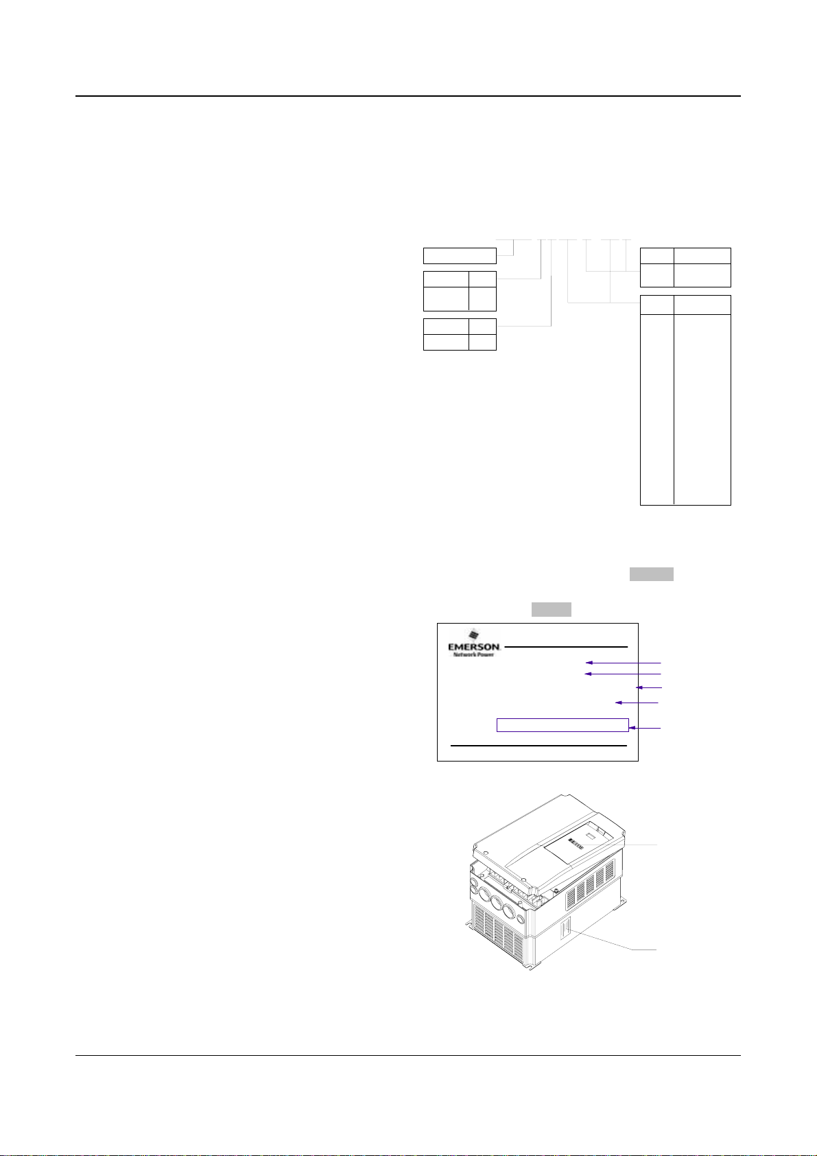
Model designation rules
220V 2
380V 4
Input volt Code
3-phase
The nameplate is located on the right hand side of the
heatsink. The contents are shown in Fig.A-2. A barcode
on the plastic cover also contains the information of the
drive, as shown in Fig.A-3.
EV2000 -4 T 0055 G / 0075 P
Drive series
Code
Volt
T
Fig. A-1 Explanations of Drive Models
MODEL:
POWER
INPUT
OUTPUT
S/N:
EV2000-4T0055G/0075P
5.5kW/7.5kW
:
3PH AC 380V-440V 15.5/20.5A 50Hz/60Hz
:
8.5/11KVA 13/17A 0-650Hz 0-440V
:
Emerson Network Power Co., Ltd.
Fig. A-2 Nameplate Description
Preface 1
Drive type
Code
G
Fixed torque
P
Fan & pump
Motor power
Code
0055 5.5
0075 7.5
0110 11
0150 15
0185 18.5
0220 22
0300 30
0370 37
0450 45
0550 55
0750 75
0900 90
1100 110
1320 132
1600 160
2000 200
2200 220
2800 280
kW
model
motor power
barcode
Barcode
Fig. A-3 Locations of Nameplate and Barcode
EV2000 Series Universal Variable Speed Drive User Manual
Nameplate
2 Chapter 1 Safety
Chapter 1 Safety
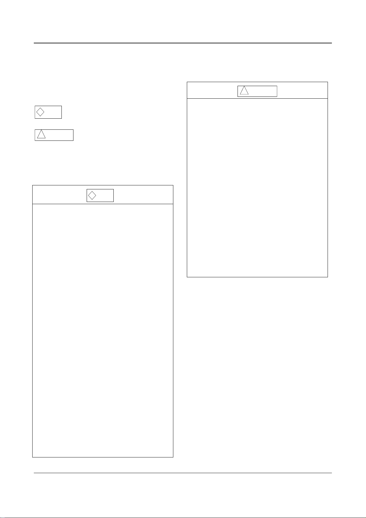
1.1 Safety
Danger
!
!
Attention
1.2 Notes for Installations
·Please install the drive on fire-retardant material.
·Keep the drive away from combustible materials
·Keep the drive away from explosive gas
·Only qualified personnel shall wire the drive
·Never wire the drive unless the input AC supply is
totally disconnected
·The drive must be properly earthed to reduce
electrical accident
·Install the cover before switching on the drive, to
reduce the danger of electric shock and explosion.
·For drives that have been stored for longer than 2
years, increase its input voltage gradually before
supplying full rated input voltage to it, in order to
avoid electric shock and explosion
·Don’t touch the live control terminals with bare
hands
·Don’t operate the drive with wet hands
·Perform the maintenance job after confirming that
the charging LED is off or the DC Bus voltage is
below 36V.
·Only trained professionals can change the
components, it is prohibited to leave wires or metal
parts inside the drive so as to avoid the risk of fire.
·Parameter settings of the control board that has
been changed must be revised, otherwise accidents
may occur.
·The bare portions of the power cables must be bound
with insulation tapes.
Operations without following
instructions can cause personal
injury or death.
Operations without following
instructions can cause personal
injury or damage to product or other
equipment.
Danger
!
!
Attention
·Don’t carry the drive by its cover. The cover cannot
support the weight of the drive and may drop.
·Please install the drive on a strong support, failing
which the drive may fall off.
·Don’t install the drive in places where water pipes
may leak onto it.
·Don’t allow screws, washers and other metal foreign
matters to fall inside the drive, otherwise there is a
danger of fire or damage;
·Don’t operate the drive if parts are not complete,
otherwise there is a danger of a fire or human injury;
·Don’t install the drive under direct sunshine,
otherwise it may be damaged;
·Don’t short circuit P1/PB and terminal (-), otherwise
there is a danger of fire or the drive may be
damaged.
·Cable lugs must be connected to main terminals
firmly
· Don’s apply supply voltage (AC 220V or higher) to
control terminals except terminals TA, TB and TC.
1.3 Notes for Using EV2000
Pay attention to the following issues when using EV2000
drive.
1.3.1 About Motor and Load
Compared to the power frequency operation
EV2000 series drives are voltage type variable speed
drive. The output voltage is in PWM wave with some
harmonics. Therefore, temperature rise, noise and
vibration of motor are higher.
Low Speed Rotating with Constant Torque
Driving a common motor at low speed for a long time,
the drive’s life will be reduced due to the deteriorating
heat dissipation effect, so a special variable frequency
motor is needed if long time operation with constant
torque is required.
Motor’s over-temperature protecting threshold
The drive can protect the motor from over-temperature.
If the ratings of the driven motor are not in compliance
EV2000 Series Universal Variable Speed Drive User Manual

Chapter 1 Safety 3
with the drive, be sure to adjust the protective threshold
to ensure the motor is properly protected.
Operate above 50Hz
When running the motor above 50Hz, there will be
increase in vibration and noise. The rate at which the
torque is available from the motor is inversely
proportional to its increase in running speed. Ensure that
the motor can still provide sufficient torque to the load.
Lubrication of mechanical devices
Over time, the lubricants in mechanical devices, such as
gear box, geared motor, etc. when running at low speed,
will deteriorate. Frequent maintenance is recommended.
Braking Torque
Braking torque is developed in the machine when the
drive is hoisting a load down. The drive will trip when it
cannot cope with dissipating the regenerative energy of
the load. Therefore, a braking unit with proper
parameters setting in the drive is required.
The mechanical resonance point of load
The drive system may encounter mechanical resonance
with the load when operating within certain band of
output frequency. Skip frequencies have been set to
avoid it.
The drive should be started and stopped via its control
terminals. It is prohibited to start and stop the drive
directly through input line contactors, which may
damage the drive with frequent operations.
Insulation of Motors
Before using the drive, the insulation of the motors must
be checked, especially, if it is used for the first time or if
it has been stored for a long time. This is to reduce the
risk of the Drive from being damaged by the poor
insulation of the motor. Wiring diagram is shown in Fig.
1-1. Please use 500V insulation tester to measure the
insulating resistance. It should not be less than 5MΩ.
Motor
Mega-Ohm-Meter
Earthing
conductor
Fig. 1-1 Checking the insulation of motor
1.3.2 About Variable Speed Drive
Varistors or Capacitors Used to Improve the Power
Factor
Don’t connect any varistor or capacitor to the output
terminals of the drive, because the drive’s output voltage
waveform is pulse wave, otherwise tripping or damaging
of components may occur; in addition, don’t install circuit
breaker or contactor at the output side of the drive as
shown in Fig.1-2.
EV2000
U
V
W
M
Fig. 1-2 Capacitors are prohiBited to be used.
Circuit breakers connected to the output of the drive
If circuit breaker or contactor needs to be connected
between the drive and the motor, be sure to operate
these circuit breakers or contactor when the drive has
no output, to avoid damaging of the drive.
Using outside the range of rated voltage
The drive is not suitable to be used out of the specified
range of operation voltage. If needed, please use
suitable voltage regulation device.
Change from 3-phase to 2-phase
It is not recommended to change the drive from 3-phase
input to 2-phase input. If it is necessary to use on two
phases, the phase-loss protection function of the drive
should be disabled. The Drive must be derated for this
operation. For motors at which power is above 30kW, if
it is changed into 2-phase input, then the input phases
must be at phase R and phase T, or else the drive will
not work.
After the 3-phase input is changed into 2-phase input,
bus-voltage and current ripple may increase, which not
only influences the life of electrolytic capacitor but it also
deteriorates the performance of the drive. The drive’s
operating current should be derated and should not
exceed 67% of rated value.
Protection against lightning strike
There are transient surge suppressors inside the Drive
which protects it against lighting strike.
EV2000 Series Universal Variable Speed Drive User Manual

4 Chapter 1 Safety
Derating due to Altitude
Derating must be considered when the drive is installed
at high altitude, greater than 1000m. This is because the
cooling effect of Drive is deteriorated due to the thin air,
as shown in Fig.1-3 that indicates the relationship
between the elevation and rated current of the Drive.
Iout
100%
90%
80%
1000
400030002000
m)
(
Fig. 1-3 Derating Drive’s output current with altitude
1.4 Disposing Unwanted Drive
When disposing the Drive, pay attention to the following
factors:
The capacitors may explode when they are burnt.
Poisonous gas may be generated when the plastic parts
like front covers are burnt.
Disposing method: Please dispose the Drive as
industrial waste.
EV2000 Series Universal Variable Speed Drive User Manual

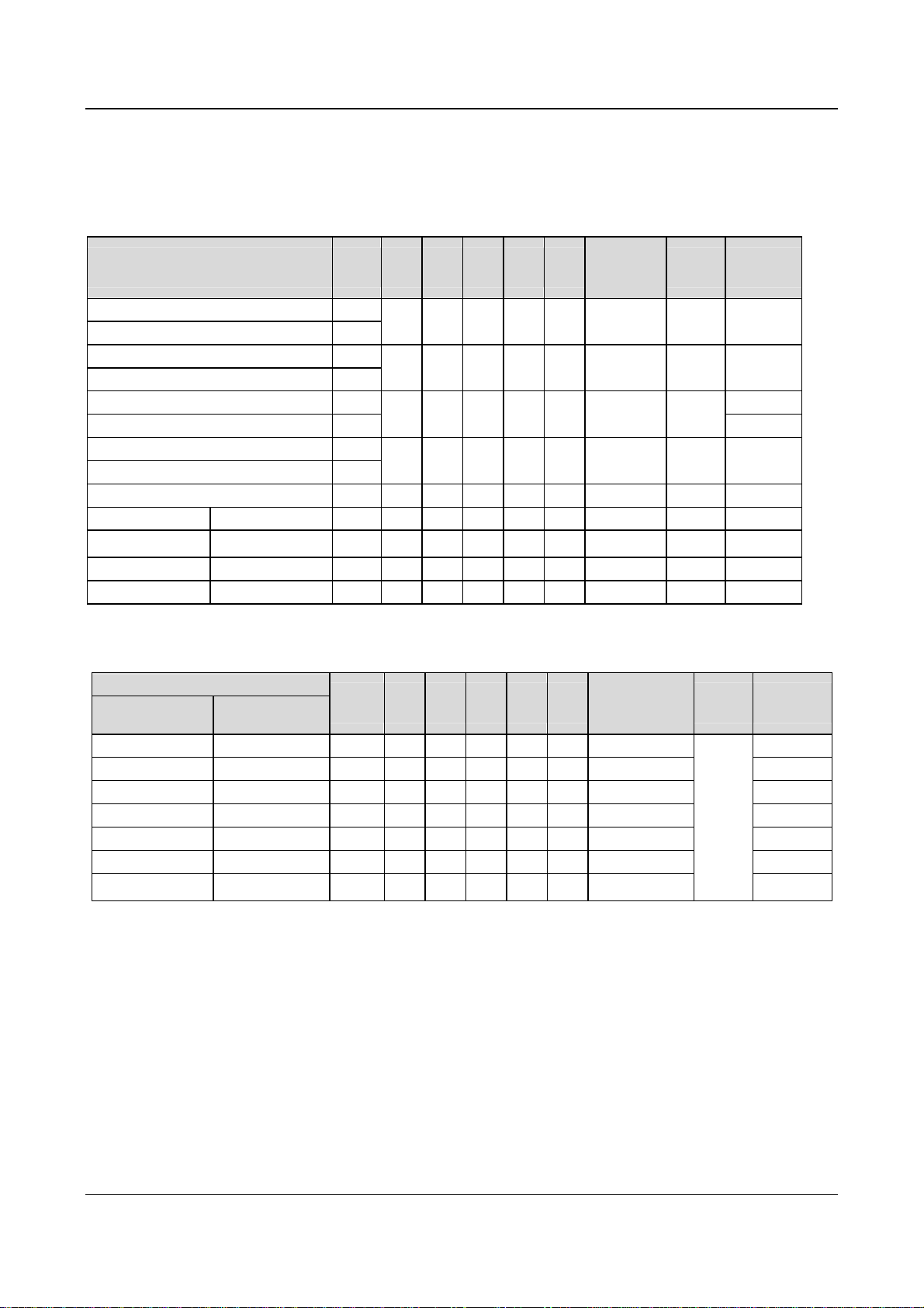
2.1 Specifications
Item Description
Chapter 2 Product Introduction 5
Chapter 2 Product Introduction
Table 2-1 General specifications
Input
Output
Main control
functions
Rated voltage & frequency Three-phase,380V~440V; 50Hz/60Hz
Permissible fluctuation range
Rated voltage 380V
Frequency 0Hz~650Hz
Over load ability
Modulation mode
Speed range
Starting torque
Steady accuracy of speed
Accuracy of frequency
Setting frequency resolution
Torque boost
V/F curve
Acc/Dec curve
DC injection braking
Jog
Multi-step speed running
Voltage:320V~460V;Voltage unbalance rate:<3%; Frequency:±5%
Type G: 150% rated current for 1 minute, 200% rated current for 0.5
second;
Type P: 110% rated current for 1 minute, 150% rated current for 1
second
Flux vector PWM modulation
1:100
180% rated torque at 0.50Hz
≤±0.5% rated synchronous speed
Digital setting: highest frequency×±0.01%;analog setting: highest
frequency×±0.2%
Digital setting:0.01Hz;analog setting: highest frequency×0.1%
Auto torque boost, Manual torque boost0.1%~30.0%
4 modes: 1 V/F curve mode set by user and 3 kinds of torque-derating
modes (2.0 order, 1.7 order, and 1.2 order)
3 modes: linear Acc/Dec, S ramp Acc/Dec and auto Acc/Dec; Acc/Dec
time(maximum: 60 hours) and unit(second or minute) are settable.
Initial frequency of DC injection braking process: 0.20~60.00Hz,
braking time: 0.0~30.0s
braking current: Type G: 0.0~100.0%
Type P: 0.0~80.0%
Range of jog frequency:0.20Hz~50.00Hz; Acc/Dec time of Jog operation:
0.1~60.0s, Interval of Jog operation is also settable.
Multi-step speed running can be realized by internal PLC or control
terminal
Internal PI Be able to form simple control system easily
Auto-energy saving operation
Auto voltage regulation(AVR)
Auto current limiting
Auto adjusting of carrier
frequency
EV2000 Series Universal Variable Speed Drive User Manual
V/F curve is optimized automatically according to the load condition to
realize energy-saving operation.
When source voltage changes, the modulation rate can be adjusted
automatically, so that the output voltage is unchanged.
Operating current is limited automatically to avoid frequent tripping of the
drive.
Optional function. The carrier frequency can be adjusted automatically
according to the load condition.

6 Chapter 2 Product Introduction
Item Description
Traverse operation
Fixed-length control
Droop control
Customized
function
Tone adjusting
Non-stop operation upon power
failure
Bundling function
Methods of inputting operating
commands
Methods of setting up
Operating
function
frequency
Auxiliary frequency reference
Pulse output terminal
Analog output terminals
LED display
Operation
panel
LCD display
Parameter copy
Keys locking up and function
selection
Protection function
Optional parts
Application environment
Elevation Lower than 1000m
Environment
Ambient temperature
Humidity
Vibration
Storage temperature
Structure
Protection level
Cooling
Mount modes
Efficiency
Traverse operating function with adjustable central frequency
The drive stops when preset fixed length is reached
Used in the application that several drives drive one motor.
Adjust the tone of the operating motor
Uninterrupted operation can be realized by controlling the bus voltage
when power failure occurs.
Control mode and reference selector (for example panel input or analog
VCI input) can be selected together at one time
Commands can be input by terminals and serial ports.
Digital setting; Analog voltage/current setup; pulse frequency setup; set
via serial port and different setting modes are selectable
Realize flexible fine tuning of auxiliary frequency.
0~50kHz pulse signal output. Signals like frequency setting and output
frequency can be output.
2 analog outputs of 0/4~20mA and 0/2~10V(selectable). Be able to
output signals like reference frequency and output frequency.
Be able to display about 20 kinds of parameters such as frequency
setting, output frequency, output voltage and current, etc.
Optional, Chinese/English display
Fast parameter copy can be realized by using LCD panel.
Be able to lock part or all the keys. Be able to define the functions of part
of the keys to avoid wrong operation.
Phase failure protection, Over current protection; Over voltage protection;
Under voltage protection; Over heat protection; overload protection
LCD operation panel, braking kit, remote mounted keypad, remote control
cable and field bus adapter
In-door, free from direct sunlight, dust, corrosive gas, combustible gas, oil
mist, steam, water drop or salt
-10℃~+40℃(ambient temperature is within 40℃~50℃, deration is
required)
Less than 95%RH, without condensation
2
Less than 5.9m/s
(0.6g)
-40℃~+70℃
IP20
Fan cooling
Mounted on the wall or inside cabinet
For 45kW or below: ≥93%, 55kW or above: ≥95%
EV2000 Series Universal Variable Speed Drive User Manual

Chapter 2 Product Introduction 7
2.2 Product Series
2.2.1 Ratings
Table 2-2 Variable Speed Drive series(55P or below)
Drive model (55P or below)
(G: constant torque, P: Fan & pump)
EV2000-4T0055G/0075P 8.5/11 15.5/20.5 13/17 5.5/7.5
EV2000-4T0075G/0110P 11/17 20.5/26 17/25 7.5/11
EV2000-4T0110G/0150P 17/21 26/35 25/32 11/15
EV2000-4T0150G/0185P 21/24 35/38.5 32/37 15/18.5
EV2000-4T0185G1/0220P1 24/30 38.5/46.5 37/45 18.5/22
EV2000-4T0220G1/0300P1 30/40 46.5/62 45/60 22/30
EV2000-4T0300G1/0370P1 40/50 62/76 60/75 30/37
EV2000-4T0370G1/0450P1 50/60 76/92 75/90 37/45
EV2000-4T0450G1/0550P1 60/72 92/113 90/110 45/55
Drive model (55G or above)
Constant torque Fan & pump
EV2000-4T0550G
EV2000-4T0750G EV2000-4T0750P 100 157 152 75
EV2000-4T0900G EV2000-4T0900P 116 180 176 90
EV2000-4T1100G EV2000-4T1100P 138 214 210 110
EV2000-4T1320G EV2000-4T1320P 167 256 253 132
EV2000-4T1600G EV2000-4T1600P 200 307 304 160
EV2000-4T2000G EV2000-4T2000P 250 385 380 200
EV2000-4T2200G EV2000-4T2200P 280 430 426 220
-
EV2000-4T2800P 342 525 520 280
-
Rated capacity
(kVA)
Table 2-3 Variable Speed Drive series(55G or above)
Rated
capacity
(kVA)
72 113 110 55
Rated input current
(A)
Rated input current
(A)
Rated output current
Rated output current
(A)
(A)
Motor power
(kW)
Motor power
(kW)
Notes:
1. Models in shady area are under development.
2. Please contact the manufacturer for models of EV2000-4T2800G and EV2000-4T3150P.
EV2000 Series Universal Variable Speed Drive User Manual
8 Chapter 2 Product Introduction
2.2.2 Parts of Variable Speed Drive
Port for operation
panel
Multi-function
terminal
Control
board
Control terminal
Charge
indicator
Cover’s
mounting hole
Cover
Compartment for
operation panel
Barcode
Mounting
hole
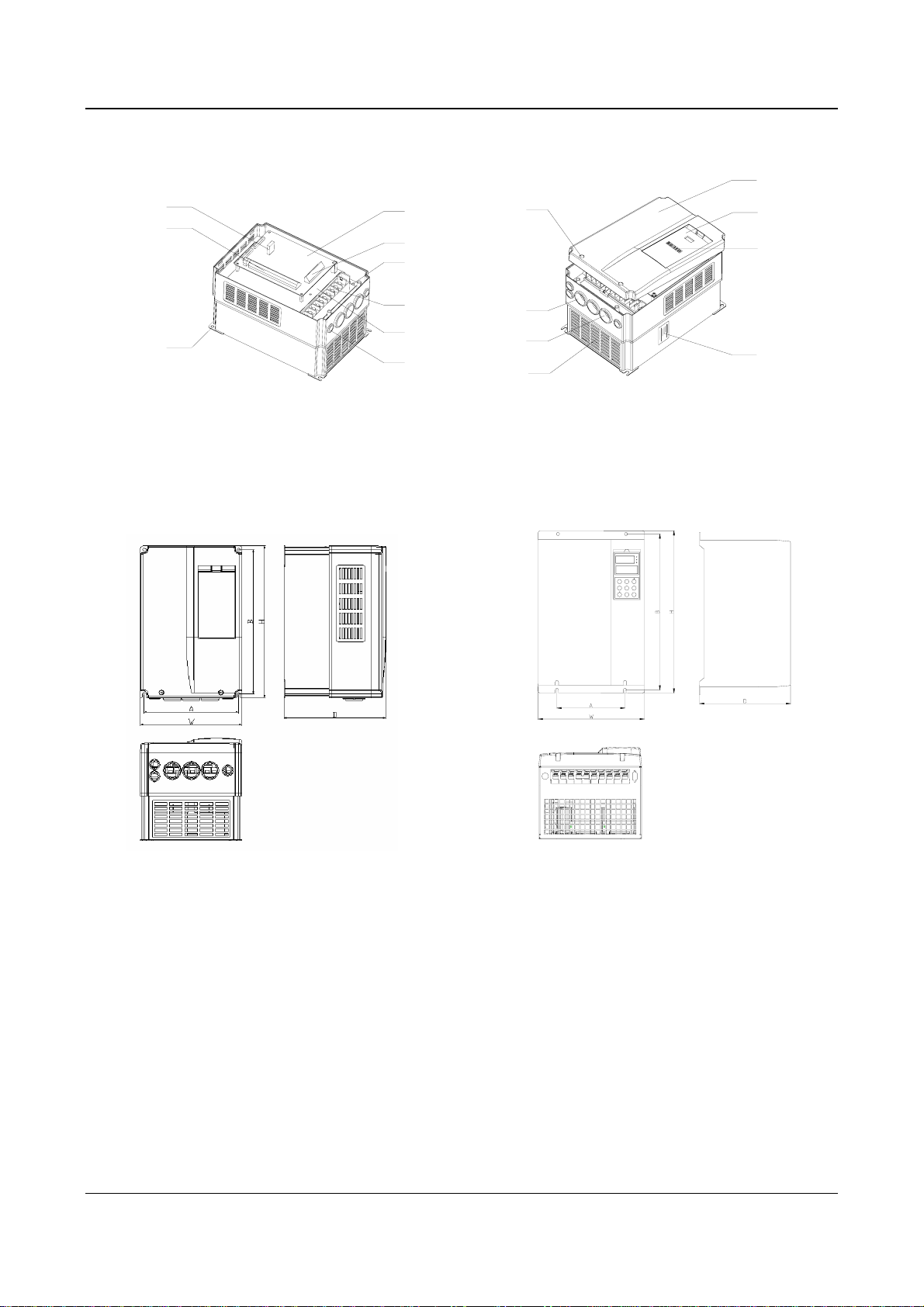
2.2.3 Outline and Gross Weight
1. Outline
Power terminal
shielding
board
Inlet holes for
signal cables
Power
terminal
Outlet holes for
AC output holes
Ventilation
holes
Fig. 2-1 Parts of drive
Nameplate
Fig. a EV2000-4T0055G/0075P~ Fig. b EV2000-4T0185G1/0220P1~
EV2000-4T0150G/0185P EV2000-4T0220G1/0300P1
EV2000 Series Universal Variable Speed Drive User Manual
Chapter 2 Product Introduction 9
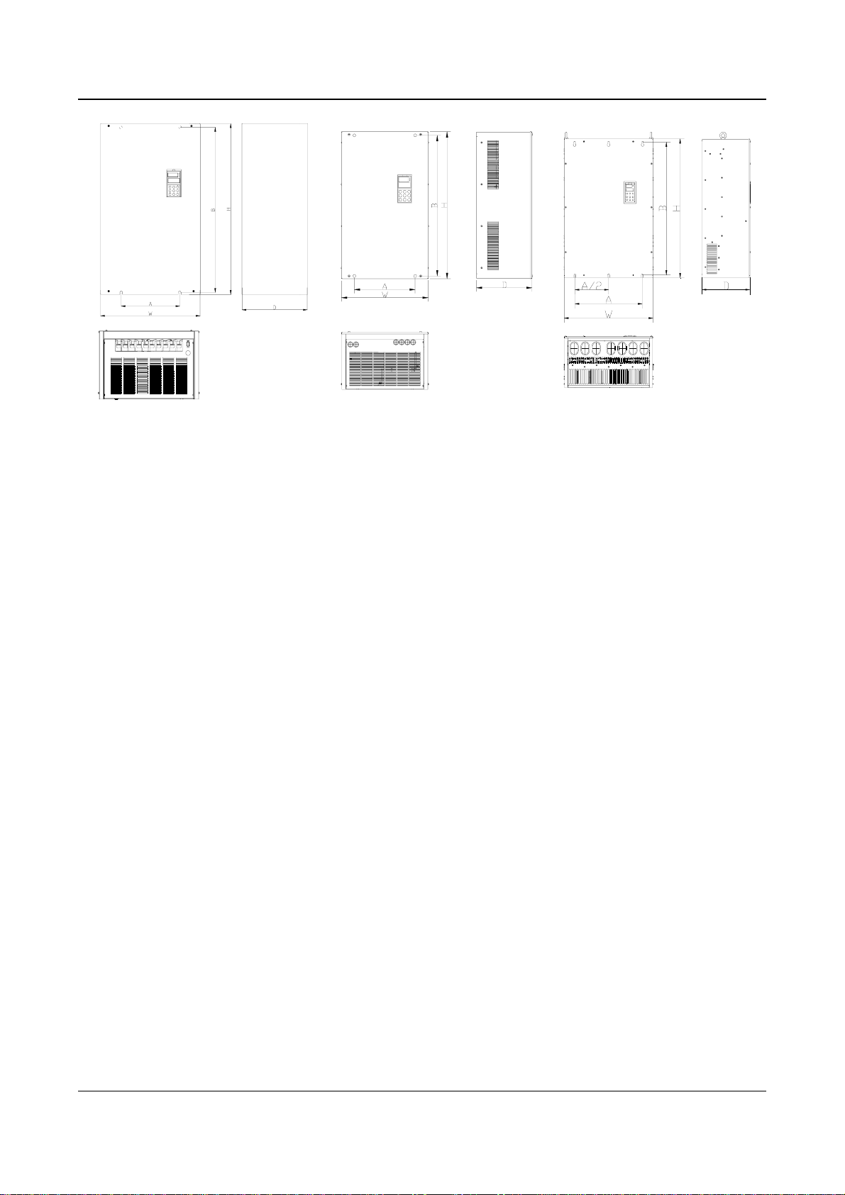
Fig. c EV2000-4T0300G1/0370P1~ Fig. d EV2000-4T0550G~ Fig. e EV2000-4T01100G~
EV2000-4T0450G1/0550P1 EV2000-4T01100P EV2000-4T2800P
Fig. 2-2 Outline of EV2000
EV2000 Series Universal Variable Speed Drive User Manual
10 Chapter 2 Product Introduction
2. Mechanical parameters
Table 2-4 Mechanical parameters 1
EV2000-4T0055G/0075P~EV2000-4T0450G1/0550P1、EV2000-4T0550G、EV2000-4T0750G、EV2000-4T0750P、
EV2000-4T0900P、EV2000-4T0900G、EV2000-4T1100P
Drive model (55P or below)
(G: constant torque, P: Fan & pump)
EV2000-4T0055G/0075P
EV2000-4T0075G/0110P
EV2000-4T0110G/0150P
EV2000-4T0150G/0185P
EV2000-4T0185G1/0220P1 18.5/22 13
EV2000-4T0220G1/0300P1 22/30
EV2000-4T0300G1/0370P1 30/37
EV2000-4T0370G1/0450P1 37/45
Motor
(kW) A (mm)B (mm)H (mm)W(mm)D (mm)
5.5/7.5
7.5/11
11/15
15/18.5
186 285 300 200 202 6.8 Fig. a 7.5
236 365 380 250 209 6.8 Fig. a 12
180 421 435 275 209 7 Fig. b
250 600 624 375 262 9 Fig. b 35
Diameter of
mounting
hole(mm)
Fig.
Number
Gross
weight(kg)
15
EV2000-4T0450G1/0550P1 45/55 38
EV2000-4T0550G _
EV2000-4T0750G EV2000-4T0750P
EV2000-4T0900G EV2000-4T0900P
EV2000-4T1100P
55 300 747 770 468 301 10 Fig. d 50
75 300 747 770 468 301 10 Fig. d 50
90 300 747 770 468 301 10 Fig. d 90
110 300 747 770 468 301 10 Fig. d 90
Table 2-5 Mechanical parameters 1
EV2000-4T1100G~EV2000-4T2200G. EV2000-4T2200P. EV2000-4T2800P
Drive model
Constant torque Fan & pump
Motor
(kW) A (mm)B (mm)H (mm)W(mm)D (mm)
Diameter of
mounting holes
(mm)
Fig.
Number
Gross
weight (kg)
EV2000-4T1100G — 110 370 855 880 530 370 14 100
EV2000-4T1320G EV2000-4T1320P 132 370 855 880 530 370 14 100
EV2000-4T1600G EV2000-4T1600P 160 370 855 880 530 370 14 100
— EV2000-4T2000P 200 370 855 880 530 370 14 100
Fig. e
EV2000-4T2000G — 200 520 975 1000 680 370 14 140
EV2000-4T2200G EV2000-4T2200P 220 520 975 1000 680 370 14 140
— EV2000-4T2800P 280 520 975 1000 680 370 14
140
Notes:
1. Models in Table 2-5 are under developing.
2. For 75kWG drive or above, DC reactor is included in its standard configuration. The weight of DC reactor in the above table is
not included in the gross weight. Outline and dimensions of DC reactor are shown below.
EV2000 Series Universal Variable Speed Drive User Manual

Chapter 2 Product Introduction 11
Diameter of terminal
Enlarged view of terminal
Mounting hole
Mounting hole
Fig. 2-3 Dimensions of DC reactor
Table 2-6 Mechanical Parameters of DC Reactor
Applicable
drive
(kW)
75G
Model of DC
reactor
Recommended
size of copper
(mm2)
A B C D E F G H I J
TDL-4DI01-0900 60 190 160 125 161 120 80 10 250 280 25
Size(mm)
Diameter
of terminal
φ
12
90G/90P
110G/110P TDL-4DI01-1100 100 190 160 125 161 120 80
132G/132P TDL-4DI01-1320 150 200 170 135 171
160G/160P TDL-4DI01-1600 150 210 180
200G/200P 200
220G/220P
TDL-4DI01-2200
280P TDL-4DI01-2800 325
250
220 190
220 190
135 171
135 171
145 181 160 95
120
85
130 85 12 280 320 30
150 90
10
10
12
12 315
280
250
260
280
25
30
315 340 40
340 40
φ
φ
φ
φ
φ
12
12
12
15
15
Notes:
1. Columns B and C in Table 2-6 are the sizes of mounting holes of DC reactor.
2. DC reactor should be installed at the bottom of the cabinet if it is to be installed inside a cabinet. The clearance between reactor
and the drive should be at least 35cm, and the reactor should be as far away from the air inlet port of the drive as possible.
Gross
weight
(kg)
23
25
28
32
40
45
EV2000 Series Universal Variable Speed Drive User Manual
12 Chapter 2 Product Introduction
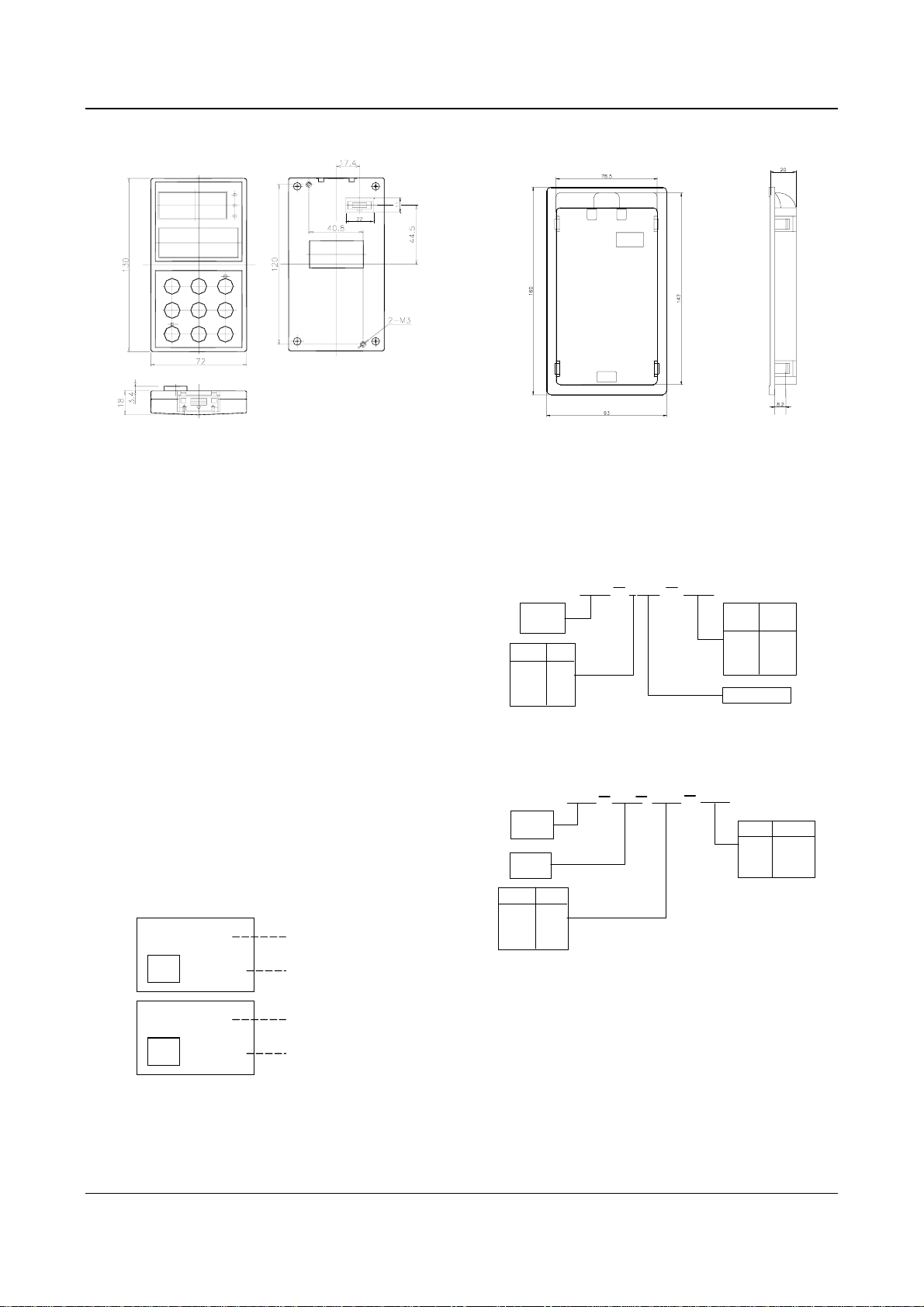
3. Optional panel and mounting box
a) Operation panel b) Mounting box (Model: EVF-KB02)
Fig. 2-4 Operation panel and mounting box
2.3 Optional Parts
All the optional parts are given below, make additional
orders if needed.
2.3.1 LCD Operational Panel
Model:TDP-LCD03
Language: Chinese/English optional
LCD operation panel can perform fast parameter copy.
Interface: As shown in Fig. 2-5, the interface is divided
into main display area, operation instruction area and
explanations for operation instructions.
Main display area: Display the status, parameters.
Operation display area: Display the next operation, if
there are several operations for selection, the operation
contents will be displayed in this area one by one.
Explanations for operations: Display the explanations for
the “operation display area”
Freq. Set Mode
E/D
Parameter
FREQ SET
Main display area
Operation display are
Main display area
2.3.2 Braking Kits
1. Braking kit
4C01 0150
Code
220V 2
380V 4
660V 6
Braking unit
Braking
kit
Code
Volt
220V 2
380V 4
660V 6
TDB
Fig. 2-6 Model of braking kit
2. Braking resistor
0400
Code
0400 2
0200 4
0100 6
Braking
Kit
Braking
resistor
Code
Power
1.5kW 0015
3.0kW 0030
5.0kW 0050
TDB
R01
0015
Fig. 2-7 Explanations of Model of braking resistor
Motor
power
Resistor
E/D
DATA SET
Operation display are
Fig. 2-5 LCD display interface
EV2000 Series Universal Variable Speed Drive User Manual
Chapter 2 Product Introduction 13
3. Configurations
Table 2-7 Specifications of braking kit and resistor
Rated motor
power(kW)
Model of braking
resistor
Ratio of working time of
braking kit to drive’s total
working time (%)
Braking
torque (%)
Maximum
continuous
operating time(s)
Model of braking
kit
5.5 — 10 100 10 Built-in
7.5 — 10 100 10 Built-in
11 TDB-R01-0015-0400 10 100 10 TDB-4C01-0150
15 TDB-R01-0015-0400 10 100 10 TDB-4C01-0150
18.5 TDB-R01-0015-0400 10 100 10 TDB-4C01-0150
22 TDB-R01-0030-0200 10 100 10 TDB-4C01-0300
30 TDB-R01-0030-0200 10 100 10 TDB-4C01-0300
37 TDB-R01-0030-0200 10 100 10 TDB-4C01-0300
45 TDB-R01-0050-0100 10 100 10 TDB-4C01-0550
55 TDB-R01-0050-0100 10 100 10 TDB-4C01-0550
75 TDB-R01-0050-0100 10 100 10 TDB-4C01-0550
Notes
1. There is a braking kit inside the 7.5kW drive or below. An external braking resistor is needed to be connected if dynamic
braking is required and the recommended resistor is 1000W/100Ω.
2. The 90kW drive or above should use several braking kits connected in parallel (TDB-4C01-0550).
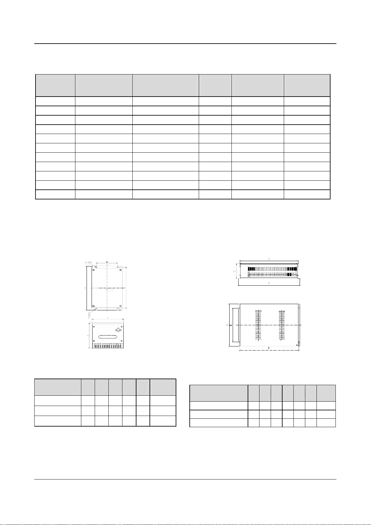
4. Outline and installation sizes
Fig. 2-8 Installation dimensions of braking kit
Table 2-8 Installation dimensions of braking kit(unit: mm)
Model of braking
kit
A B C D E
Gross
weight
TDB-4C01-0150 254 143 144 240 100 3 kg
TDB-4C01-0300 254 143 144 240 100 3 kg
TDB-4C01-0550 254 130 170 240 126 4 kg
EV2000 Series Universal Variable Speed Drive User Manual
Fig. 2-9 Installation dimensions of braking resistor
Table 2-9 Installation dimensions of braking resistor
(unit: mm)
Model of braking
resistor
A B C D E F
Gross
weight
TDB-4R01-0015-0400 475 228 127 447 177 460 3 kg
TDB-4R01-0030-0200 500 350 128 480 298 490 6 kg
TDB-4R01-0050-0100 540 520 170 520 470 530 8 kg
5. Functions and wiring
A. Wire connections braking resistor and braking kit

14 Chapter 2 Product Introduction
EV2000
U
R
V
W
S
PE
T
(-)
(+)
M
PR
TA
P
TB
TC
N
braking unit braking resistor
P
PR
TH1
TH2
Fig. 2-10 Connecting the braking kit to the Drive
TA-TB and TA-TC are contacts of relay used for
outputting fault indicating signal, and TH1 and TH2 are
contacts of temperature relay (relay used for outputting
over-heat indicating signal).
B. Main functions of braking kit
Activation voltage for braking is adjustable;
Protection against excessive duty-cycle of braking
resistor;
Overheat protection of heatsink;
Alarm indication for power module’s fault;
Fault indication and indication for fault relay output;
The braking resistor will be disconnected automatically if
it is over-heated and the relay will output alarming
signal.
The cables connected between the braking kit and the
drive, and those between the braking kit and braking
resistor should be less than 5m. If longer than 5m,
twisted-pair cable should be used and the maximum
length is 10m.
2.3.3 Communication Parts
1. Communication cables
A. Cables of operation panel
Model: TDC-CB0015(1.5m)
TDC-CB0030(3.0m)
The cables are used to connect the panel to the drive.
B. Communication cables of remote mounted keypad
Two models: FRC21W1(3.0m) FRC21W2(30m)
The cables are used to connect the remote mounted
keypad to the drive.
2. Remote mounted keypad
Model: TDO-RC02
It uses the same structure with operation panel of the
drive. It is easily to be installed and secured and
convenient for hand-held operation. Its display is similar
to the operation panel.
RS485 communication mode is used between the drive
and the remote mounted keypad. A 4-core cable is used
to connect the drive and the keypad, and the maximum
distance can be 1000m. Master/slave communication
mode is used. The keypad is the master and the drive is
the slave. Cable terminals can be secured by common
screws, which makes it convenient for maintenance.
One remote mounted keypad can control several drives
by connecting the communication cables of 485+ and
485- of each drive to form a RS485 network.
Functions:
1) Be able to control the start, stop, jog operation, fault
reset of slave drives and change the frequency settings
and operation direction.
2) Identify the type of slave machine automatically. Be
able to monitor the operating frequency, frequency
setting, output voltage and current, analog close-loop
feedback, analog close-loop setting and external
counting value automatically.
3. Fieldbus adapter
Model: TDS-PA01
Be able to connect ENYDRIVE drive to PROFIBUS
network via the TDS-PA01 fieldbus adapter. In the
PROFIBUS network system, the drive operates as a
slave.
Functions:
1) To send control commands to drive (such as: start,
stop and jog);
2) To send speed or frequency reference signal to the
drive;
3) To read operating status information and actual
values from the drive;
4) To reset the drive when fault occurs in it.
4. DrvWindows host monitoring software
Version: DrvWindows V1.2
Used in the control network formed by TD1000, TD2000
and TD2100 series drive via RS485 bus. It can monitor
the operating status of the drive connected to the bus
and realize the central management of the drive. The
software’s friendly interfaces make the operation
convenient. This software now support EV2000 drive.
Functions:
Polling of slave drives, frequency setting, operating and
stopping, changing and querying the settings of
parameter.
5. Keypad Holder
Model: EVF-KB02
EV2000 Series Universal Variable Speed Drive User Manual
Chapter 3 Installation and Wiring 15
Chapter 3 Installation and Wiring
3.1 Installation Environment
Please mount the drive vertically inside a well-ventilated
location.
When selecting mounting environment, the following
issues should be taken into account:
Ambient temperature should be within the range of
-10℃~40℃. If the temperature is higher than 40 ℃, the
drive should be derated and forced ventilation is
required;
Humidity should be lower than 95% non-condensing
Mount in the location where vibration is less than
2
5.9m/s
(0.6G);
Mount in the location free of direct sunlight, dust, metal
powder, corrosive gas or combustible gas.
If there are any special requirements for installation,
please contact us for clarifications.
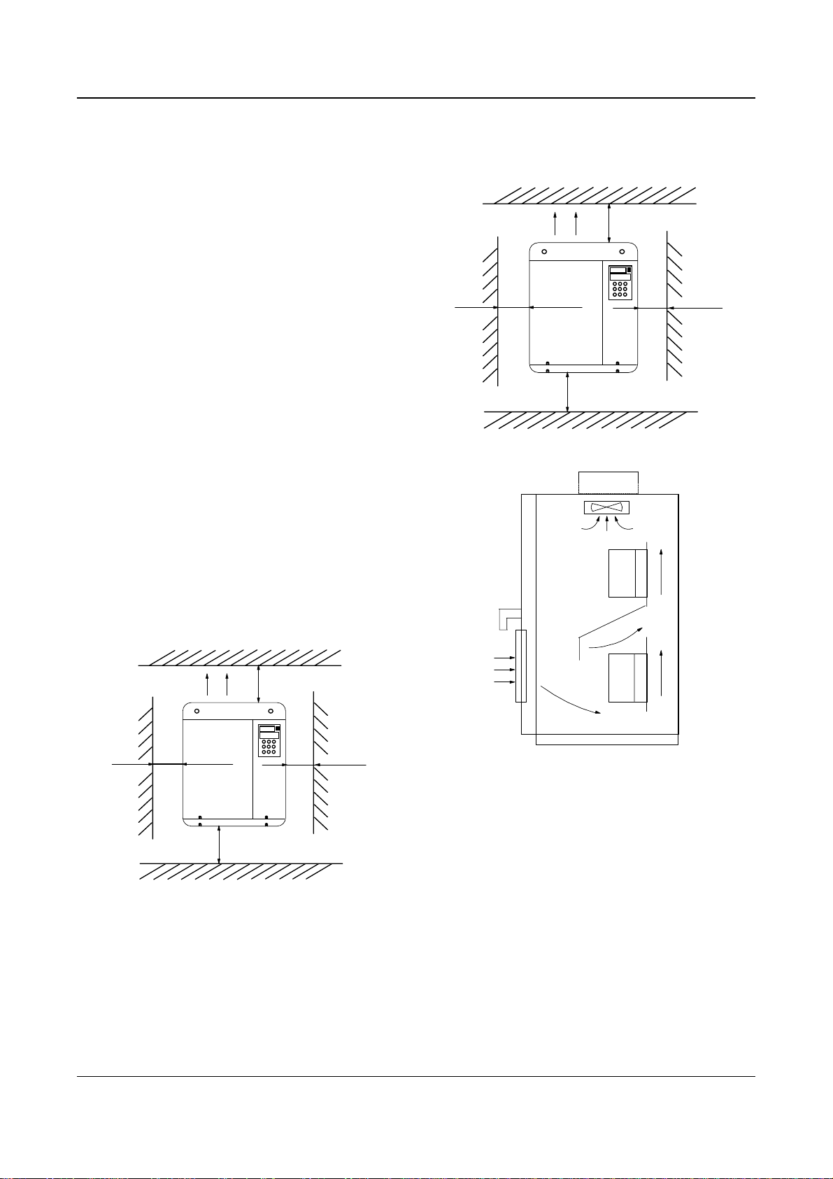
The requirements on mounting space and clearance are
shown in Fig. 3-1 and Fig. 3-2.
When two Variable Speed Drives are mounted one on
top the other, an air flow diverting plate should be fixed
in between as shown in Fig. 3-3.
air expulsion by
fan
15cm
or
above
35cm
or above
15cm
or
above
35cm
or above
Fig. 3-2 Installation clearance(55kW or above)
Drive
air expulsion by fan
10cm
or above
5cm
or
above
10cm
or above
Fig. 3-1 Installation clearance (45kW or below)
5cm
or
above
Drive
Fig. 3-3 Installation of several drives
3.2 Removing and Mounting of Parts
3.2.1 Removing and Installation of Operation Panel
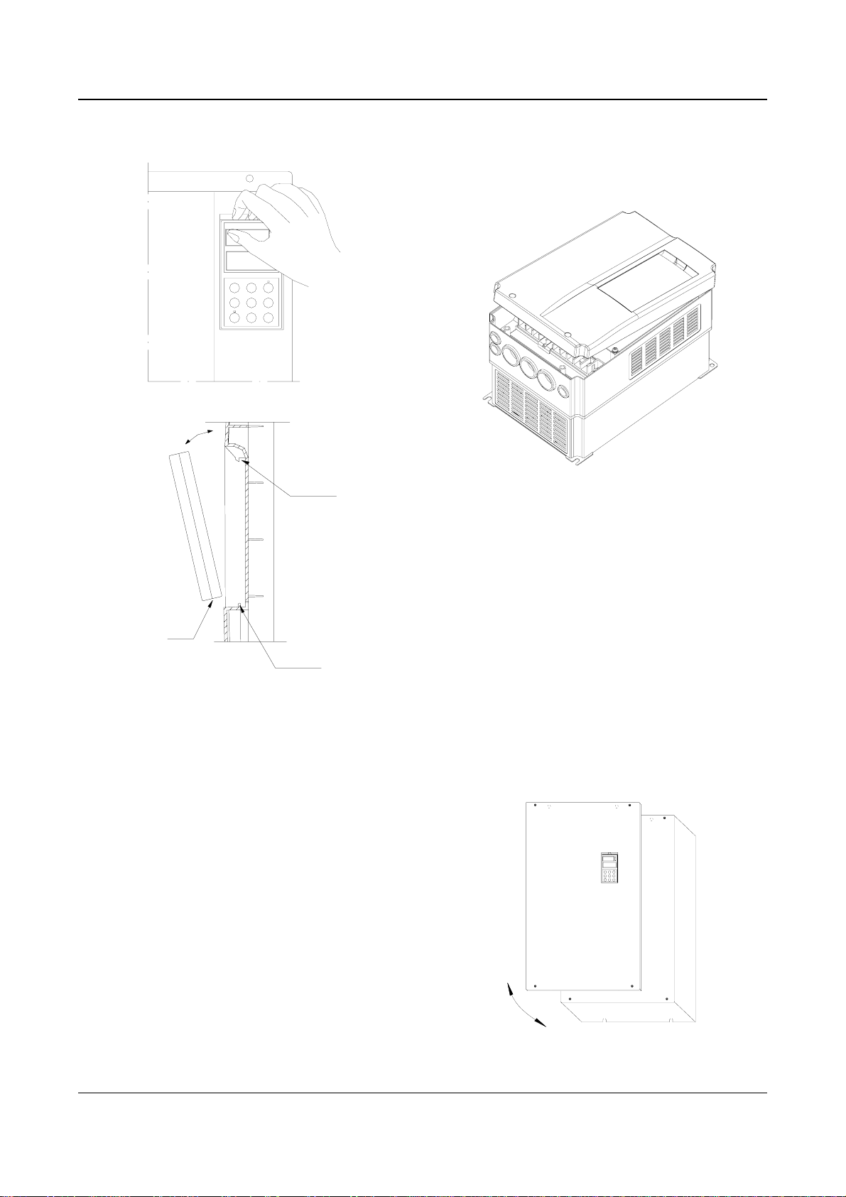
1. Disassembly
Put your middle finger into the hole on the top of
operation panel, press down the snapper and pull the
panel outward as shown in. Figure 3-4.
2. Installation
Place the bottom edge of the operation panel at the
hooks of the mounting groove and press down the
EV2000 Series Universal Variable Speed Drive User Manual
16 Chapter 3 Installation and Wiring
snapper with your middle finger. Then press the panel
inward to snap it in position as shown in Figure 3-4.
②Insert the top clamp into the slot at the top of the
drive;
③Mount the screws at the bottom part of the cover;
④Install the operation panel
Fig. 3-5 Removing and installation of plastic cover
Note:
Pull out or insert the plastic cover gently, otherwise the
mounting clamp may be damaged.
Fig. 3-4 Removing and Mounting of Operation Panel
Where: 1&2: holding clamp 3:panel
3.2.2 Removing and Mounting of Cover
EV2000 series have two kinds of cover, plastic or
metallic one. Follow the steps below to remove and
mount the cover.
1. Removing and mounting of plastic covers
1) Removing:
① Remove the operation panel
② Remove two screws at bottom
③ Lift the bottom of cover up to 5~10 degrees, move it
upward at least 10mm until the clamp are out of the slot
on the cabinet, then remove the front panel.
2) Mounting of plastic cover:
①Tilt the cover 5~10 degree;
2. Procedures of removing and mounting the metal
cover
1) Procedures of removing the metal cover:
①Remove the operational panel;
②Remove all the screws on the cover;
③Take out the cover horizontally.
2) Procedures of installing the metal cover:
①Mount the cover on the frame by screws;
②Install the operation panel.
Fig. 3-6 Removing and mounting metal cover
EV2000 Series Universal Variable Speed Drive User Manual
Chapter 3 Installation and Wiring 17
3.3 Wire Connections of Drive
Danger
!
·Wiring can only be done after the drive’s AC
power is disconnected, all the LEDs on the
operation panel are off and waiting for at least 5
minutes. Then, you can remove the panel.
·Wiring job can only be done after confirming the
charge indicator on the right bottom has
extinguished and the voltage between main circuit
power terminals + and — is below DC36V.
·Wire connections can only be done by trained and
authorized personnel.
·Check the wiring carefully before connecting
emergency stopping or safety circuits.
·Check the drive’s voltage level before supplying
power to it, otherwise human injuries or equipment
damage may happen.
!
Attention
·Check whether the Variable Speed Drive’s rated
input voltage is in compliant with the AC supply
voltage before using.
·Dielectric strength test of the drive has been done
in factory, so you need not do it again.
·Refer to chapter 2 on connected braking resistor
or braking kit.
·It is prohibited to connect the AC supply cables to
the drive’s terminals U, V and W.
·Grounding cables should be copper cables with
section area bigger than 3.5mm
grounding resistance should be less than 10Ω.
·There is leakage current inside the drive. The total
leakage current is greater than 3.5mA, depending
on the usage conditions. To ensure safety, both the
drive and the motor should be grounded, and a
leakage current protector (RCD) should be
installed. It is recommended to choose B type RCD
and set the leakage current at 300mA.
·The drive should be connected to the AC supply
via a circuit breaker or fuse to provide input
over-current protection or convenience for
disconnecting the AC supply to maintain the drive.
Wire the drive according to Fig. 3-7 during
commissioning :
2
, and the
QF
R
3-phase
AC
supply
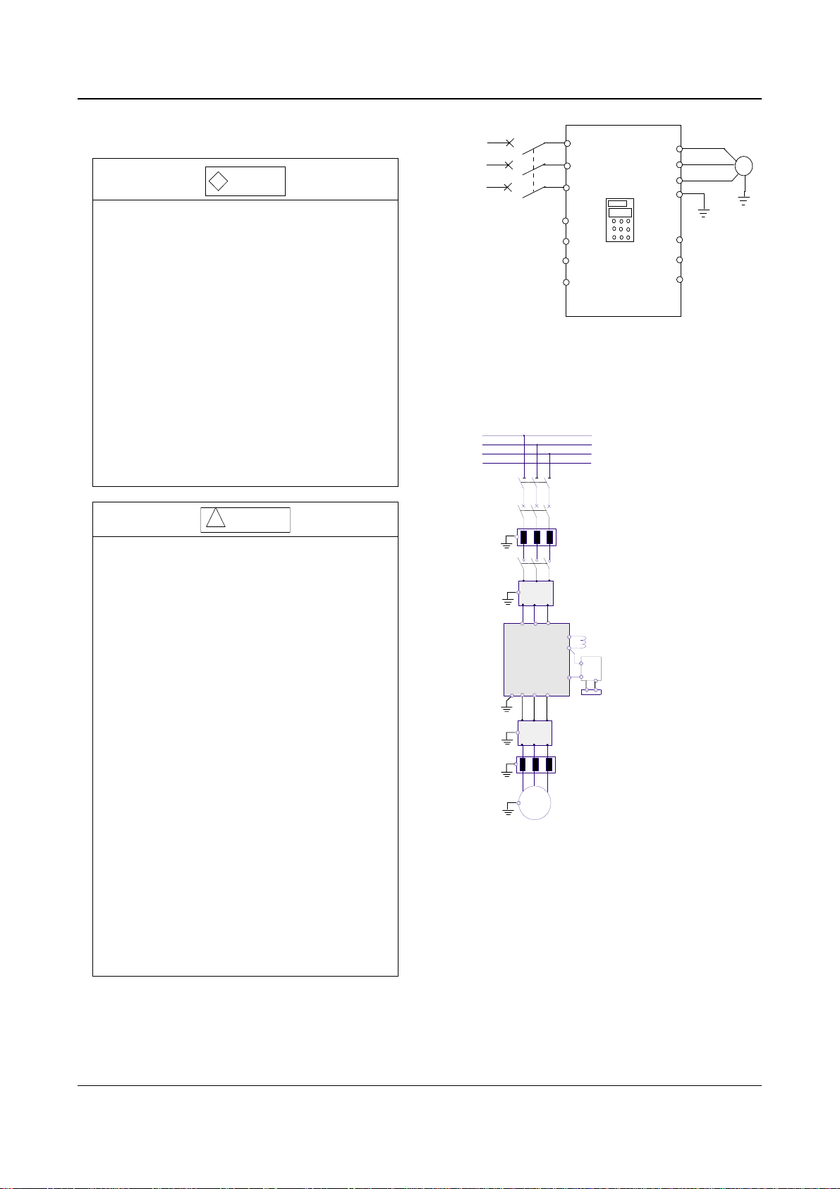
3.3.1 Wire Connections of Main Terminals
1. Connection between drive and optional parts
R
S
T
N
PE U V W
Fig. 3-8 Wire connection between the drive and optional parts
1). Isolation switch should be connected between the
AC supply and the drive to ensure the safety of the
maintenance engineer.
2). Circuit breaker (QF) or fuse should be connected
between the AC supply and the drive to isolate the fault
of other equipment. Refer to Table 3-1 for the selection
of circuit breaker.
3) When a contactor is used for controlling the AC
supply, don’t use it to switch on or off the Variable
Speed Drive.
R S T
EV2000
M
IM
S
T
Fig. 3-7 Wiring
P1
EV2000
.
VRF
.
VCI
.
CCI
.
GND
Isolator switch
Circuit breaker or
fuse
AC input reactor
Contactor
Input EMI filter
+
—
DC reactor
Braking unit
Braking resistor
Output EMI filter
AC output reactor
FWD
REV
COM
U
V
W
PE
M
.
.
.
EV2000 Series Universal Variable Speed Drive User Manual
18 Chapter 3 Installation and Wiring
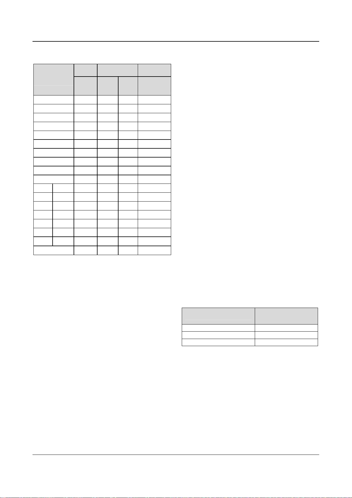
Table 3-1 Recommended capacity of circuit breaker and
the cross sectional area of copper cable
Model
EV2000-4T
Input
switch
Circuit
breaker
QF(A)
Main circuit
(mm2)
Input
Output
cable
cable
Control circuit
(mm2)
Control
terminal
0055G/0075P 32 4 4 1
0075G/0110P 40 6 6 1
0110G/0150P 63 6 6 1
0150G/0185P 63 6 6 1
0185G/0220P 100 10 10 1
0220G/0300P 100 16 16 1
0300G/0370P 125 25 25 1
0370G/0450P 160 25 25 1
0450G/0550P 200 35 35 1
0550G 200 35 35 1
0750G 0750P 250 70 70 1
0900G 0900P 315 70 70 1
1100G 1100P 400 95 95 1
1320G 1320P 400 150 150 1
1600G 1600P 630 185 185 1
2000G 2000P 630 240 240 1
2200G 2200P 800
2800P 1000
150×2 150×2
185×2 185×2
1
1
Note:
1, Parameters in the table are recommended values.
2, The input protection fuses of inverters
EV2000-4T0185G1/ 0220P1 and EV2000-4T0220G1/
0300P1 are respectively the RT16 Series 63A and 80A
products of Xi’an Fusegear Manufacture Company.
4). DC reactor
DC reactor is required for the drive whose power is
greater than EV2000-4T0750G, for the drive whose
power is lower than EV2000-4T0750P, it is optional.
Under following conditions, a DC reactor should be used
to reduce the impact of AC supply to the drive and to
protect the drive and suppress the high-order
harmonics.
(1) If a capacitor tank used for reactive power
compensation or a SCR load shares the same AC
supply with the drive, the harmonics caused by the SCR
load or the capacitor tank when it is switched on or off
may damage the drive’s input rectifying circuit;
(2) When the unbalance rate of 3-phase AC supply of
the drive is greater than 3%;
(3) If the input power factor of the drive is required to be
greater than 0.93;
(4) When a large capacity transformer is connected to
the drive, the input current of the drive may damage the
rectifying circuit. Generally, if the input AC supply
capacity of the drive is above 550KVA, or if the input AC
supply capacity is 10 times that of the drive, a DC
reactor is required to connect to the drive.
(5) Input AC Line Reactor
A line reactor should be used if the distortion of power
network is severe or the input current harmonic level is
high even after a DC reactor has been connected to the
drive. It can also be used to improve the AC input power
factor of the drive.
6) Output AC Line Reactor
When the cables from the drive to motor are longer than
80m, multi-stranded cables and an AC line reactor
should be used to suppress the high frequency
harmonics. Thus, the motor insulation is protected
against heat due to harmonics, leakage current is
reduced and the drive will not trip frequently.
(7) Input EMI filter
An EMI filter can be used to suppress the high
frequency noise generated by the drive’s power cables.
(8) Output EMI filter
An EMI filter can be used to suppress the drive’s output
noise and leakage current of cables.
(9) Safety ground
Since there is leakage current inside the drive, to ensue
safety, both the drive and the motor should be grounded,
the grounding resistance should be less than 10Ω. The
ground wire should be as short as possible. Please refer
to the section of the earth wire in Table 3-2.
Table 3-2 Section of Ground Wire
Cable Section (mm2)
S≤16
16<S≤35
35<S
Min. section of ground
wire Sp(mm2)
S
16
S/2
Note that the data in the above table apply when the
conductor connected with the ground wire are made of
the same metal, otherwise, please calculate the
equivalent section based on the conductivity.
Notes:
1. EV2000 drive can meet the requirements of IEC 61800-3
after EMI filter is installed.
2. Installation of input and output EMI filters must be as
close to the drive as possible. Refer to Section 3.4 of
Chapter 3 for EMC installation instructions.
3. Refer to Section 2.3 of Chapter 2 and Appendix 2 for the
technical parameters of optional parts.
EV2000 Series Universal Variable Speed Drive User Manual
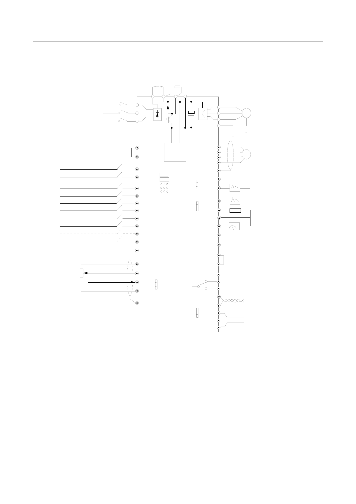
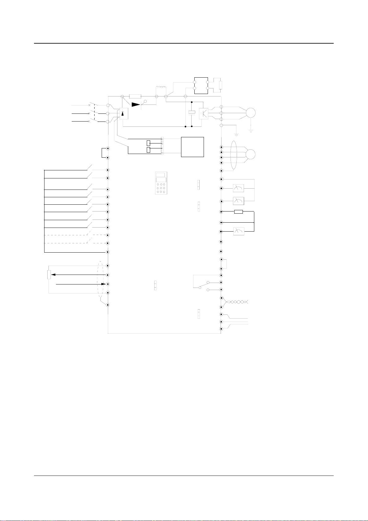
2. Wire Connections of Drive for Basic Operation
Models: EV2000-4T0055G/0075P. EV2000-4T0075G/0110P
DCL DC reactor
(connect optional parts
3-phase
380V
50/60Hz
R
S
T
externally)
Breaker
P1
R
S
T
(+)
PB
Braking resistor
(connect optional parts
externally)
(-)
Chapter 3 Installation and Wiring 19
U
V
W
PE
M
Forward/stop
Reverse/stop
Multi-function input 1
Multi-function input 2
Multi-function input 3
Multi-function input 4
Multi-function input 5
Multi-function input 6
Multi-function input 7
Multi-function input 8
Speed command
0~10V
0~10V/0~20mA
EV2000
.
I
.
.
V
Aux.
Power
supply
0/4~20mA
0/4~20mA
P24
PLC
FWD
REV
X1
X2
X3
X4
X5
X6
X7
X8
COM
VRF
VCI
CCI
GND
CN10
PE
Fig. 3-9 Basic wiring 1
0~10V
0~10V
RS232
RS485
.
.
.
CN16
.
.
.
CN17
.
.
.
CN14
P24
COM
X7
X8
PE
GND
AO1
AO2
P24
DO
COM
Y2
CME
COM
485+
485-
TXD
RXD
GND
Y1
Output 1
Output 2
TA
TB
TC
PG
DC current
meter
0/4-20mA current
signal
Output 0-24V pulse
signal
Frequency meter
Bi-direction open
collector output
Common terminal
Programmable
relay output
RS485
communication port
RS232
communication
port
Notes:
1. Terminal CCI can be input voltage or current signal by switching the jumper CN10 on control board;
2. The auxiliary power supply comes from the bus (+) and bus (-);
3. Built-in braking kit is installed and a braking resistor is required to be connected between (+) and PB;
4. In the above figure, “O” is the terminal in main circuit, and “⊙” is the control terminal;
5. Refer to section 3.3.2 for the using of control terminals.
EV2000 Series Universal Variable Speed Drive User Manual

20 Chapter 3 Installation and Wiring
Applicable models: EV2000-4T0110G/0150P~EV2000-4T2800P
3-phase
380V
50/60Hz
Multi-function input1
Multi-function input2
Multi-function input3
Multi-function input4
Multi-function input5
Multi-function input6
Multi-function input7
Multi-function input8
R
S
T
Forward/stop
Reverse/stop
Speed command
0~10V
0~10V/0~20mA
DCL DC reactor
(connect externally,optional
parts for 75kW or below)
Breaker
P1
R
S
T
P24
PLC
FWD
REV
X1
X2
X3
X4
X5
X6
X7
X8
COM
VRF
VCI
.
CCI
.
.
GND
CN10
PE
Fig. 3-10 Basic wiring 2
Braking resistor
or braking unit
(+)
R0
T0
0/4~20mA
(-)
Aux.
Power
supply
0/4~20mA
0~10V
0~10V
EV2000
I
V
RS232
RS485
PP
N
.
.
.
CN16
.
.
.
CN17
.
.
.
CN14
PB
COM
CME
COM
P24
X7
X8
PE
GND
AO1
AO2
P24
DO
COM
Y1
Y2
485+
485TXD
RXD
GND
(Connect optional parts
externally)
U
V
W
PE
Output 1
Output 2
TA
TB
TC
M
PG
DC current
meter
0/4-20mA current
signal
Output 0-24V pulse
signal
Frequency meter
Bi-direction open
collector output
Common terminal
Programmable
relay output
RS485
communication port
RS232
communication
port
Notes:
1. Terminal CCI can be input voltage or current signal by switching the jumper CN10 on control board;
2. The auxiliary power supply’s AC supply comes from R0 and T0 which are shorted with R and T of 3-phase input. If you want
to use an external AC supply, the shorting bars between R and R0, T and T0 have to be removed before connecting the external
AC supply via R0 and T0. Otherwise, short-circuit will occur.
3. It is prohibited to connect to the control power supply without disconnecting the short-circuit bar, so as to avoid short-circuit
accident;
4. If external braking parts are needed, then braking kit and braking resistors should be included; Pay attention to the polarity of
the braking kit when wiring;
5. In the above figure, “O” is the terminal in main circuit, and “⊙” is the control terminal;
6. Refer to section 3.3.2 for the using of control terminals.
EV2000 Series Universal Variable Speed Drive User Manual
Applicable models: EV2000-4T0185G1/0220P1~EV2000-4T0450G1/0550P1
braking unit and braking
resistor (external, optional)
PP
N
PB
(-)
3-phase
380V
50/60Hz
DCL DC reactor
(external, optional)
buffer resistor
(built-in)
breaker
R
S
T
P
R
S
T
P1
Transistor
(+)
Chapter 3 Installation and Wiring 21
U
V
W
PE
M
Foward/Stop
Reverse/Stop
MS input 1
MS input 2
MS input 3
MS input 4
MS input 5
MS input 6
MS input 7
MS input 8
Speed instruction
V
0~10
0~10V/0
~20mA
P24
PLC
FWD
REV
X1
X2
X3
X4
X5
X6
X7
X8
COM
VRF
VCI
CCI
GND
PE
R0
T0
.
.
.
CN10
I
V
Auxiliary
power
supply
0/4-20mA
0-10V
0/4-20mA
0-10V
EV2000
RS232
RS485
Fig. 3-11 Basic Wiring 3
.
.
.
CN16
.
.
.
CN17
.
.
.
CN14
P24
COM
PE
GND
AO1
AO2
P24
DO
COM
Y1
CME
COM
485+
485-
TXD
RXD
GND
X7
X8
Y2
output 1
output 2
TA
TB
TC
PG
DC current meter
0/4-20mA current signal
frequency meter (open collector output)
0-24V pulse output signal
2-way open collector output
common terminal
Programmable relay output
Standard RS485 port
Standard RS232 port
Notes:
1. Terminal CCI can be input voltage or current signal by switching the jumper CN10 on control board;
2. The auxiliary power supply of EV2000-4T0185G1/0220P1~EV2000-4T0220G1/0300P1 is from bus (+) and (-)。
3. The auxiliary power supply of EV2000-4T0300G1/0370P1~EV2000-4T0450G1/0550P1 is from R and T. If you want to use
an external AC supply, the jumper on CN4 should be connected to CN3 first, and then connect it to R0 and T0.
4. If external braking kit, the braking unit and braking resistors should be included; Pay attention to the polarity of the braking kit
when wiring;
5. In the above figure, “O” is the terminal in main circuit, and “⊙” is the control terminal;
6. Refer to section 3.3.2 for the usage of control terminals.
EV2000 Series Universal Variable Speed Drive User Manual
22 Chapter 3 Installation and Wiring
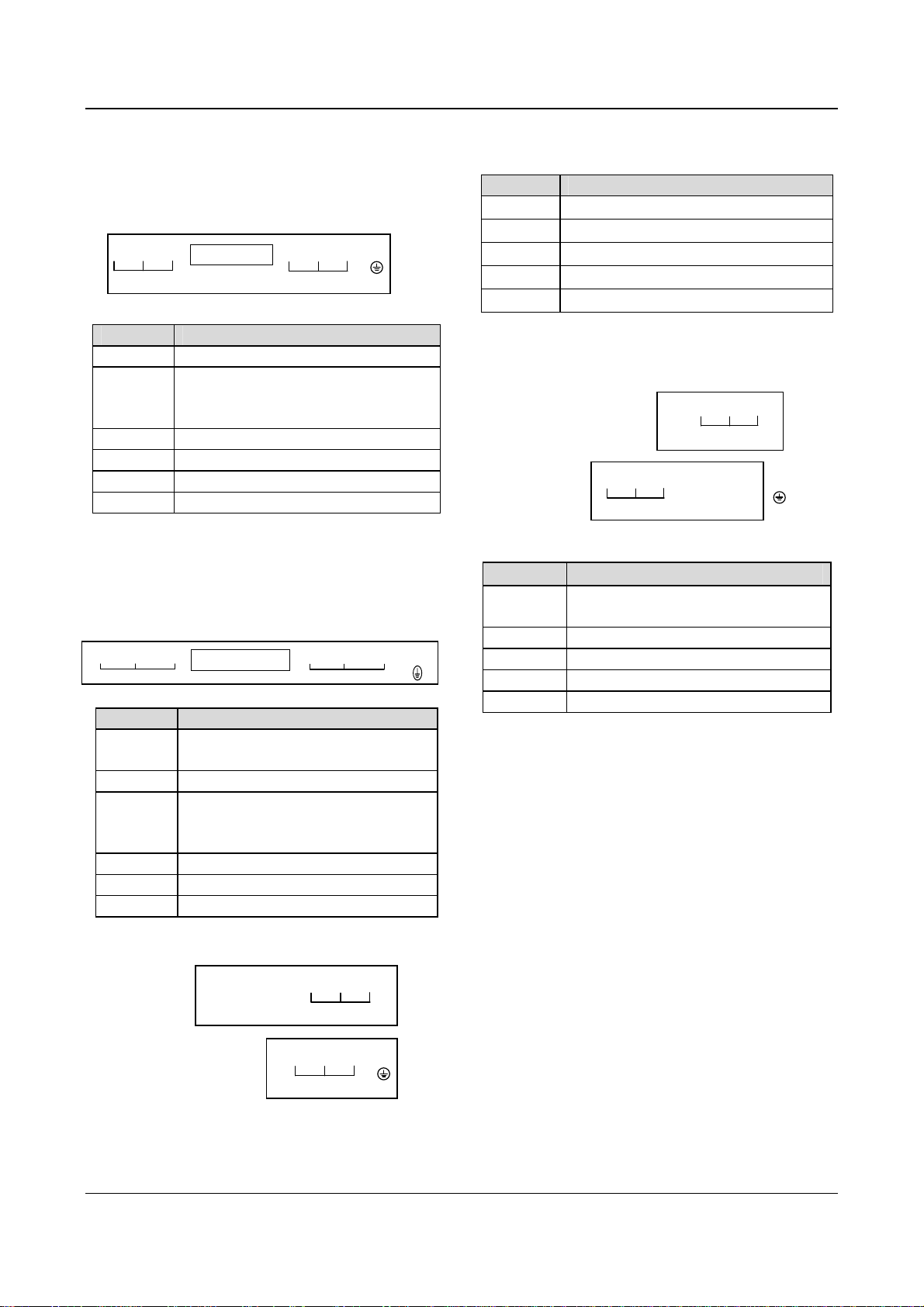
3. Input/Output Terminals in Main Circuit
1) Applicable models:
EV2000-4T0055G/0075P~EV2000-4T0150G/0185P
R S T P1 (+) PB (-) U V W PE
POWER SUPPLY MOTOR
Table 3-3 Terminals of main circuit
Terminals Function
R, S, T 3-phase 380V AC supply input terminals
Reserved terminals for DC reactor,
P1, (+)
connected with copper bar before
delivery.
(+), PB Reserved terminals for braking resistor
(-) Output terminal for DC Minus Bus
U, V, W 3-phase AC output terminals
PE Earth terminal
Notes:
Terminals PB of EV2000-4T0110G/0150P and
EV2000-4T0150G/0185P are suspended.
2) Applicable models:
EV2000-4T0185G/0220P~EV2000-4T0450G/0550P
RS T
POW ER SU PPLY
(+)
P1
P
UVW
(-)
MOTOR
Table 3-4 Terminals of main circuit
Terminals Function
R. S. T
P
3-phase 380V AC supply input
terminals
Positive pole of the rectifying bridge
Reserved terminals for DC reactor,
P1, (+)
connected by copper bar before
delivery
(-)
U. V. W
PE
Output terminal for DC Minus Bus
3-phase AC output terminals
Earth terminal
3) Applicable models:
EV2000-4T0550G. EV2000-4T0750P
To
:
(-) (+) P1 R S T
POWER SUPPLY
Table 3-5 Terminals of main circuit
Terminal Function
R, S, T
P1, (+)
(-)
U, V, W
PE
3-phase 380V AC supply input terminals
Reserved terminals for DC reactor
Output terminal for DC Minus Bus
3-phase AC output terminals
Earth terminal
4) Applicable models:
EV2000-4T0750G~EV2000-4T2200G
EV2000-4T0900P~EV2000-4T2800P
Top:
Bottom:
U V W P1 (+) (-) PE
MOTOR
R S T
POWER SUPPLY
Table 3-6 Terminals of main circuit
Terminals Function
R. S. T
3-phase 380V AC supply input
terminals
P1. (+) Reserved terminals for DC reactor
PE
(-)
U. V. W 3-phase AC output terminals
Output terminal for DC Minus Bus
PE Earth terminal
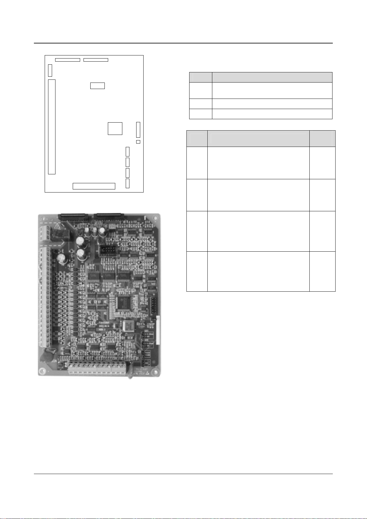
3.3.2 Wiring of Control Circuit
1. Terminals and jumpers of control board
Locations of terminals CN5, CN6 and CN7 and jumpers
CN10, CN14, CN16 and CN17 are shown in Fig. 3-.
Terminal functions are given in Table 3-6. Refer to table
3-7 for the functions and settings of jumpers. Wire the
terminals and set the jumpers correctly before using the
Drive. It is recommended to use cables bigger than
2
1mm
to connect to the terminals.
Bottom:
U V W PE
MOTOR
EV2000 Series Universal Variable Speed Drive User Manual
Chapter 3 Installation and Wiring 23
CN1 CN2
CN7
CN3
CN4
CN6
CN5
DSP
CN16
CN17
CN14
CN10
CN9
mA
V
mA
V
232
485
I
V
Fig. 3-12 Locations of jumpers on the control board
Table 3-7 Functions of terminals provided to users
SN Function
CN5
Analog input and output terminal, RS232 and
RSRS485 communication port
CN6 Digital input/output terminal
CN7 Relay output terminal
Table 3-8 Functions of jumpers provided to users
SN Function and settings
Used for selecting CCI current/voltage
CN10
input
I: 0/4~20mA current signal,
V: 0~10V voltage signal
Used for selecting communication
CN14
ports (RS232 or RS485)
RS232: Select RS232 port,
RS485: Select RSRS485 port
Used for selecting the output signal
(current or voltage) of analog output
CN16
terminal AO1;
0/4~20mA: AO1 output current signal;
0~10V: A01 output voltage signal
Used for selecting the output signal
(current or voltage) of analog output
CN17
terminal AO2;
0/4~20mA: AO2 output current signal;
0~10V: AO2 output voltage signal
Factory
settings
0~10V
RS485
0~10V
0~10V
Fig. 3-13 Control board
EV2000 Series Universal Variable Speed Drive User Manual

24 Chapter 3 Installation and Wiring
2. Wire connections of terminals on control board
1) Terminal CN5 on control board
Arrangements of terminals of CN5:
VRF VCI CCI GND AO1 AO2 GND TXD RXD 485+ 485- PE
Functions of terminals of CN5 are given in Table 3-.
Table 3-9 Functions of the terminals
Category Terminals Name Function Specification
Analog
input
RS485+ RS485 +
RS485
communication
Communication
RS485-
TXD
RXD
VCI
port
RS232
communication
port
Analog input
VCI
RS485 —
Transmitting pin
(Reference ground: GND)
Receiving pin (reference
ground: GND)
Be able to accept analog voltage input
(Reference ground: GND)
RS232/RS485
can be selected
by jumper CN14,
RS485 mode is
the default
mode.
Standard RS-485 communication
port, please use twisted-pair cable
or shielded cable.
Standard RS232 communication
port, 3-wire connection (only use
TXD, RXD and GND).
Maximum distance: 15m
Input voltage range:0~10V
(input resistance:100kΩ)
Resolution: 1/2000
Input voltage range:0~10V(input
Analog
input
CCI
Analog input
CCI
Be able to accept analog voltage/current
input. Jumper CN10 can select voltage or
current input mode, Voltage input mode is
the default mode.(reference ground: GND)
resistance:100kΩ)
Input current range:0~20mA
(input resistance:500Ω)
Resolution: 1/2000
Be able to output analog voltage/current
(total 12 kinds of signals). Jumper CN16 can
AO1 Analog output 1
select voltage or current input mode, Voltage
input mode is the default mode. Refer to
Analog
output
F7.26 for details. (reference ground: GND)
Be able to output analog voltage/current
Output current range: 0/4~20mA
Output voltage range:0/2~10V
(total 12 kinds of signals). Jumper CN17 can
AO2 Analog output 2
select voltage or current input mode, Voltage
input mode is the default mode. Refer to
F7.27 for details.(reference ground: GND)
+10V power
supply
GND of +10V
power supply
Provide +10V power supply Maximum output current is 50mA
Reference ground of analog signal and 10V
power supply
Isolated with COM and CME
Power
supply
VRF
GND
Terminal used for the earthing the shielding
Shielding
layer
PE
GND of
shielding layer
layer. The shielding layers of analog signal
cable, RS485 communication cable and
motor cable can be connected to the
Connected to PE inside the drive.
terminal.
1. Wiring analog input terminal
①VCI can accept analog voltage signal input and wiring is shown below:
EV2000 Series Universal Variable Speed Drive User Manual
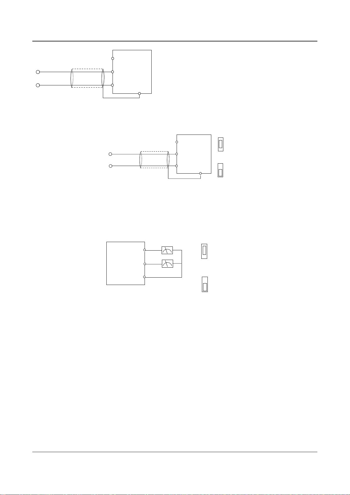
●
VRF(+10V)
Chapter 3 Installation and Wiring 25
10V
0~+
Nearer shielding wire’s end is
connected to PE
●
●
VCI
GND
EV2000
PE
●
Fig. 3-14 Wiring terminal VCI
②
CCI can accept analog signal input and the jumper can be used to select voltage input (0~10V) and current input
(0/4~20mA). The wiring is shown below:
CCI current
PE
●
I
V
···
CCI voltage
I
V
···
CN10
0~+10V
20mA
or 0/4~
Nearer shielding wire’s
end that is connected to
the PE
●
VRF(+10V)
●
CCI
●
GND
EV2000
Fig. 3-15 Wiring CCI
2. Wiring connections analog output terminal
If the analog output terminals AO1 and AO2 are connected to analog meters, then various kinds of physical values can
be indicated. The jumper can select current output (0/4~20mA) and voltage output(0/2~10V). The wiring is shown in
Fig.3-16..
Analog current
output
0/4-20mA
0-10V
···
Anlog voltage
output
0/4-20mA
0-10V
···
AO1:CN16;AO2:
CN17
EV2000
AO1
AO2
GND
Analog
meter
●
●
●
Fig. 3-16 Wiring analog output terminal
Notes:
(1) When using analog input, a common mode inductor can be installed between VCI and GND or CCI and GND.
(2) Analog input and output signals are easily disturbed by noise, so shielded cables must be used to transmit these signals and
the cable length should be as short as possible.
3. Wiring of Serial Communication Port
Wire connections of serial communication port.
EV2000 drive provides two kinds of serial ports: RS232 and RS485 which can be selected by Jumper CN14.
Wire as following figures show, and a “single-master single slave” system or a “single-master multi-slaves” system can
be formed. The drives in the network can be monitored and controlled remotely and automatically in real time by using a
PC or PLC controller. Thus more complicated operation control can be realized (e.g. Unlimited multi-step PLC
operation).
①
The drive connects to the host via its RS232 port:
EV2000 Series Universal Variable Speed Drive User Manual
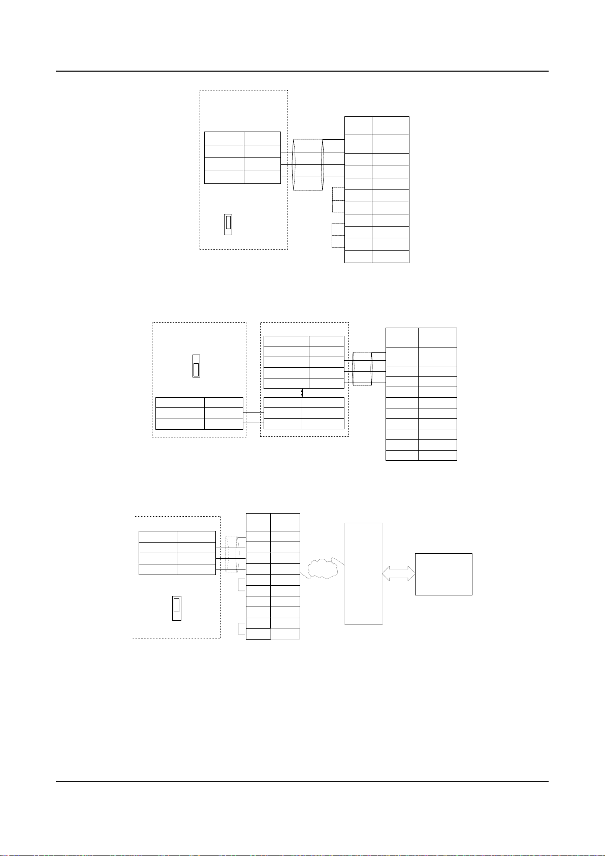
26 Chapter 3 Installation and Wiring
EV2000
RS232 port
Function Terminal
Transmit TXD
Receive RXD
GND GND
The kilobit of FF.00
is set to 0
RS232
RS485
···
CN14
Shielded
cable
Fig. 3-17 RS232-RS232 communication cables
②
Connection between the drive’s RS485 port and the host PC:
EV2000
RS485 port
RS232
RS485
···
CN14
Function Terminal
-
+
485
RS
RS485
-
+
RS485/RS232 converter
Function Terminal
5V power
Transmit TXD
Receive RXD
Ground GND
Terminal Function
-
RS485
+
485
RS
Fig. 3-18 RS485-(RS485/RS232)-RS232 communication cable
●
5V
+
-
+
Control PC
RS232
Signal Pin
PE Enclosure
RXD 2
TXD 3
GND 5
DTR 4
●
DSR 6
CD 1
●
RTS 7
CTS 8
Shielded
cable
(
DB9
RI 9
Control PC
RS232
●
●
)
(
DB9
Signal Pin
PE Enclosure
RXD 2
TXD 3
GND 5
DTR 4
DSR 6
RI 9
CD 1
RTS 7
CTS 8
)
③
Connect the drive to the host PC via a MODEM:
Signal Pin
PE
●
TXD
RXD
GND
●
DTR 4
DSR
RI
CD
RTS
CTS
MODEM
Enclosure
3
2
5
6
9
1
7
8
PSTN
Telephone
network
MODEM
RS232
(PC or PLC
EV2000
RS232 port
Func
Transmit
Receive
Ground
The kilobit of FF.00
is set to 1
Te rm i na l
···
CN14
TXD
RXD
GND
RS232
RS485
Fig. 3-19 Wiring of RS232-(MODEM-PSTN-MODEM)-RS232 communication
④
The drive’s RS485 port connects to PROFIBUS via the TDS-PA01(field bus made by ENPC):
PC
)
EV2000 Series Universal Variable Speed Drive User Manual
Loading…
- Topics
- manualsbase, manuals,
- Collection
- manuals_emerson; manuals; additional_collections
- Language
- English
- Item Size
- 2.2M
- Addeddate
- 2020-08-13 09:32:56
- Identifier
- manualsbase-id-228105
- Identifier-ark
- ark:/13960/t5t81n825
- Ocr
- ABBYY FineReader 11.0 (Extended OCR)
- Ppi
- 600
- Scanner
- Internet Archive Python library 1.9.4
plus-circle Add Review
plus-circle Add Review
comment
Reviews
There are no reviews yet. Be the first one to
write a review.
101
Views
DOWNLOAD OPTIONS
download 1 file
ABBYY GZ download
Temporarily Unavailable
DAISY
For users with print-disabilities
Temporarily Unavailable
EPUB
download 1 file
FULL TEXT download
download 1 file
ITEM TILE download
download 1 file
PAGE NUMBERS JSON download
download 1 file
PDF download
download 1 file
SINGLE PAGE PROCESSED JP2 ZIP download
download 1 file
TORRENT download
download 12 Files
download 6 Original
SHOW ALL
IN COLLECTIONS
Manuals: Emerson Electric
The Manual Library
Additional Collections
Uploaded by
chris85
on
A good user manual
The rules should oblige the seller to give the purchaser an operating instrucion of Emerson Network Power, along with an item. The lack of an instruction or false information given to customer shall constitute grounds to apply for a complaint because of nonconformity of goods with the contract. In accordance with the law, a customer can receive an instruction in non-paper form; lately graphic and electronic forms of the manuals, as well as instructional videos have been majorly used. A necessary precondition for this is the unmistakable, legible character of an instruction.
What is an instruction?
The term originates from the Latin word „instructio”, which means organizing. Therefore, in an instruction of Emerson Network Power one could find a process description. An instruction’s purpose is to teach, to ease the start-up and an item’s use or performance of certain activities. An instruction is a compilation of information about an item/a service, it is a clue.
Unfortunately, only a few customers devote their time to read an instruction of Emerson Network Power. A good user manual introduces us to a number of additional functionalities of the purchased item, and also helps us to avoid the formation of most of the defects.
What should a perfect user manual contain?
First and foremost, an user manual of Emerson Network Power should contain:
— informations concerning technical data of Emerson Network Power
— name of the manufacturer and a year of construction of the Emerson Network Power item
— rules of operation, control and maintenance of the Emerson Network Power item
— safety signs and mark certificates which confirm compatibility with appropriate standards
Why don’t we read the manuals?
Usually it results from the lack of time and certainty about functionalities of purchased items. Unfortunately, networking and start-up of Emerson Network Power alone are not enough. An instruction contains a number of clues concerning respective functionalities, safety rules, maintenance methods (what means should be used), eventual defects of Emerson Network Power, and methods of problem resolution. Eventually, when one still can’t find the answer to his problems, he will be directed to the Emerson service. Lately animated manuals and instructional videos are quite popular among customers. These kinds of user manuals are effective; they assure that a customer will familiarize himself with the whole material, and won’t skip complicated, technical information of Emerson Network Power.
Why one should read the manuals?
It is mostly in the manuals where we will find the details concerning construction and possibility of the Emerson Network Power item, and its use of respective accessory, as well as information concerning all the functions and facilities.
After a successful purchase of an item one should find a moment and get to know with every part of an instruction. Currently the manuals are carefully prearranged and translated, so they could be fully understood by its users. The manuals will serve as an informational aid.
FAQ: Types of Manuals and Their Contents
Emerson Network Power Manuals come in various types, each serving a specific purpose to help users effectively operate and maintain their devices. Here are the common types of Emerson Network Power User Guides and the information they typically include:
- User Manuals: Provide comprehensive instructions on how to use the device, including setup, features, and operation. They often include troubleshooting tips, safety information, and maintenance guidelines.
- Service Instructions: Designed for technicians and repair professionals, these manuals offer detailed information on diagnosing and repairing issues with the device. They include schematics, parts lists, and step-by-step repair procedures.
- Installation Guides: Focus on the installation process of the device, providing detailed instructions and diagrams for proper setup. They are essential for ensuring the device is installed correctly and safely.
- Maintenance Manuals: Provide guidance on routine maintenance tasks to keep the device in optimal condition. They cover cleaning procedures, part replacements, and regular servicing tips.
- Quick Start Guides: Offer a concise overview of the essential steps needed to get the device up and running quickly. They are ideal for users who need immediate assistance with basic setup and operation.
Each type of Emerson Network Power instruction is designed to address specific needs, ensuring users have the necessary information to use, maintain, and repair their devices effectively.
Related Instructions for Emerson Network Power:
1
Copeland Scroll Digital ZFD13KVE
Application manuallines Manual: Emerson Copeland Scroll Digital ZFD13KVE (BODI23, Upd.Fri 02.2025)
31
954
144
2
ER108001
Owner’s manual PDF User Manual (@1OA2RB), Emerson ER108001 Security Camera (05.04.2025)
22
559
101
3
Rosemount 3308
128
150
35
4
KTM OM-2 GRATITE
7
20
4
5
LiebertChallenger ITR
Technical data manual User Manual: Emerson LiebertChallenger ITR (J6FG8W, Upd.26/10/2024)
74
620
131
6
Rosemount 8800D Series
Safety manual Emerson Rosemount 8800D Series Guide (Safety manual), @3S11NL
30
294
74
7
HD8120
Owner’s manual Emerson HD8120 Guide (Owner’s manual), @R22H5G
27
472
104
8
Site Supervisor
141
1204
181
Network Card Devices by Other Brands:
|
HP 3900 series Setup Poster PDF User Manual (@IQGBR5), HP 3900 series Printer (Thu 01.2025) Windows is a registered trademark of Microsoft Corporation. 16 Jan 2025 | 2 |
|
|
Abocom 802.11b/g Wireless LAN PCI Card WPG2400 Specification Sheet #17NRM9: 802.11b/g Wireless LAN PCI Card WPG2400 Network Card Specification sheet 802.11b/g Wireless LAN 16 May 2025 | 3 |
|
|
Renesas Direct Dummy IC M3T-DIRECT100S Operation & User’s Manual PDF Guide (@YZ12HQ), Renesas Direct Dummy IC M3T-DIRECT100S Network Card (28th Jan 2025) ( 1 / 4 ) 28 Jan 2025 | 4 |
|
|
HP Kayak XW A2-U2-W2 Supplementary Manual Desktop #W7M7V6 Familiarization Guide 10 Apr 2025 | 12 |
Categories:
Ceiling fan
Clock
Fire and Smoke Dampers
Cutter
Office Equipment
Control valve

Submittal for SiteI/O 10/0E
Liebert Corporation
Page 1 of 4 Rev. 4; 10/03
DESCRIPTION:
The SiteI/O 10/0E is part of the SiteI/O-Line and is intended to be used with
SiteScan Web systems specifically. It is a 32 bit microprocessor-based device designed to monitor up to
ten thermistors, and/or dry contact type signals. Logically the device, sits on the Ethernet network,
providing the interface to SiteScan Web. This effectively creates a device that is a router / gateway and
I/O module in one device. Screw terminal blocks are provided to terminate power, communication, and
input signal wiring.
DIMENSIONS:
Module:
7 1/8″ H x 6 1/4″ W X 1 5/8” D
18.10cm H x 15.88cm W X 4.13cm D
Enclosure:
12”H x 14.25″ W x 2.85″ D
(painted steel)
419.1mm x 301.3mm x 78.6mm
POWER: 24 VAC ±10%, 50-60 Hz, 7.2 VA.
ENVIRONMENTAL
OPERATING RANGE:0 to 130°F (-17.8 to 54.4°C); 10 to 90% relative humidity, non-condensing.
For UUKL Smoke Control Systems, 32°-120.2°F (0°-49°C); 10 to 85% relative
humidity, non-condensing.
COMMUNICATIONS: One (1) Ethernet 10BaseT RJ-45 port
MEMORY: 1 MB flash, 1 MB RAM.
BATTERY: Seven-year lithium battery provides a minimum of 10,000 hours of data retention
during power outages.
FAULT DETECTION:Hardware watchdog timer.
PROTECTION: Built-in surge and transient protection circuitry.