
FOR SERVICE TRAINING
-Engine Mechanical Features-
4HK1-TC ENGINE
-Engine Control System & Diagnosis-
Applicable Model
Model Year Vehicle Model Main Market
2005 NPR & NQR
General Export (Euro 3 Regulation)
Europe, Australia, Thailand, South Afric a & etc .
ISUZU MOTORS LIMITED
N*R 4HK1-TC Engine-1
INTRODUCTION & ENGINE MECHANICAL FEATURES
The 2005 model year NPR/NQR truck, the 4HK1-TC
inline 4 cylinder engine replaces the 4HE1-TC engine
for advanced exhaust emission c ount ries. The 4HK 1-TC
engine has been newly developed on the basis o
previous 4HE1-TC engine, with additional features
including the employment of four valve mechanism pe
a cylinder that are operated via a single camshaft,
common rail fuel injection system, water-cooled exhaus t
gas re-circulation (EGR) system, and the change o
combustion chamber form. The larger engine
displacement and the common rail fuel injection system
have resulted in an increase both in maximum output
and torque, and met Euro 3 emission regulation
standard. Most conspicuous items are listed below.
Multi fuel injection type high-pressure common rail
system and is made with Denso.
Single overhead camshaft (OHC) w ith 4 valves per a
cylinder.
Electrical control EGR valve, water-cooled EGR
cooler.
Turbocharger with intercooler.
Engine Type Maximum Output Maximum Toruque
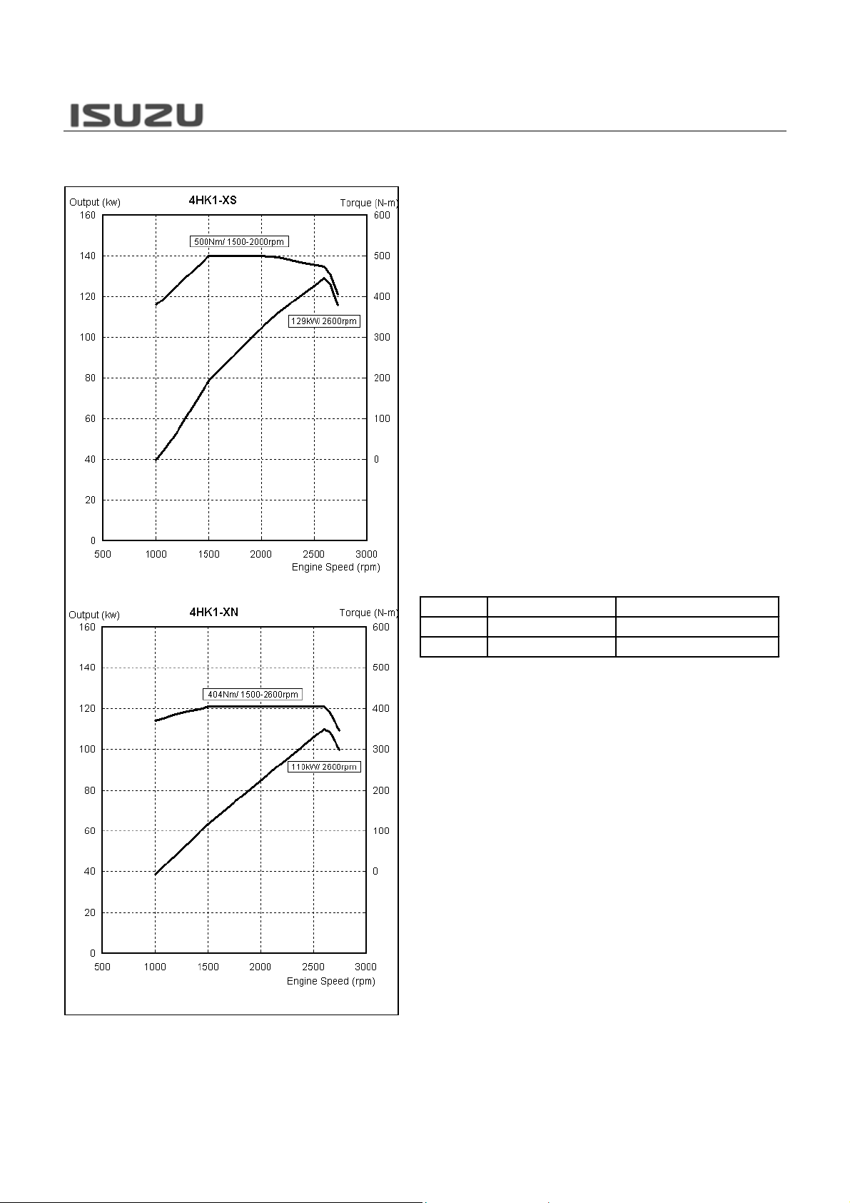
4HK1-TCS 129kw (175ps)/2600RPM 500Nm (51kgm)/1500-2000RPM
4HK1-TCN 110kw (150ps)/2600RPM 404Nm (41kgm)/1500-2600RPM
The base transmission is MYY for 4HK1-TCN low
output engine, MZZ for 4HK1-TCS high output engine.
The Smoother system is available for only MY
transmission.
N*R 4HK1-TC Engine-2
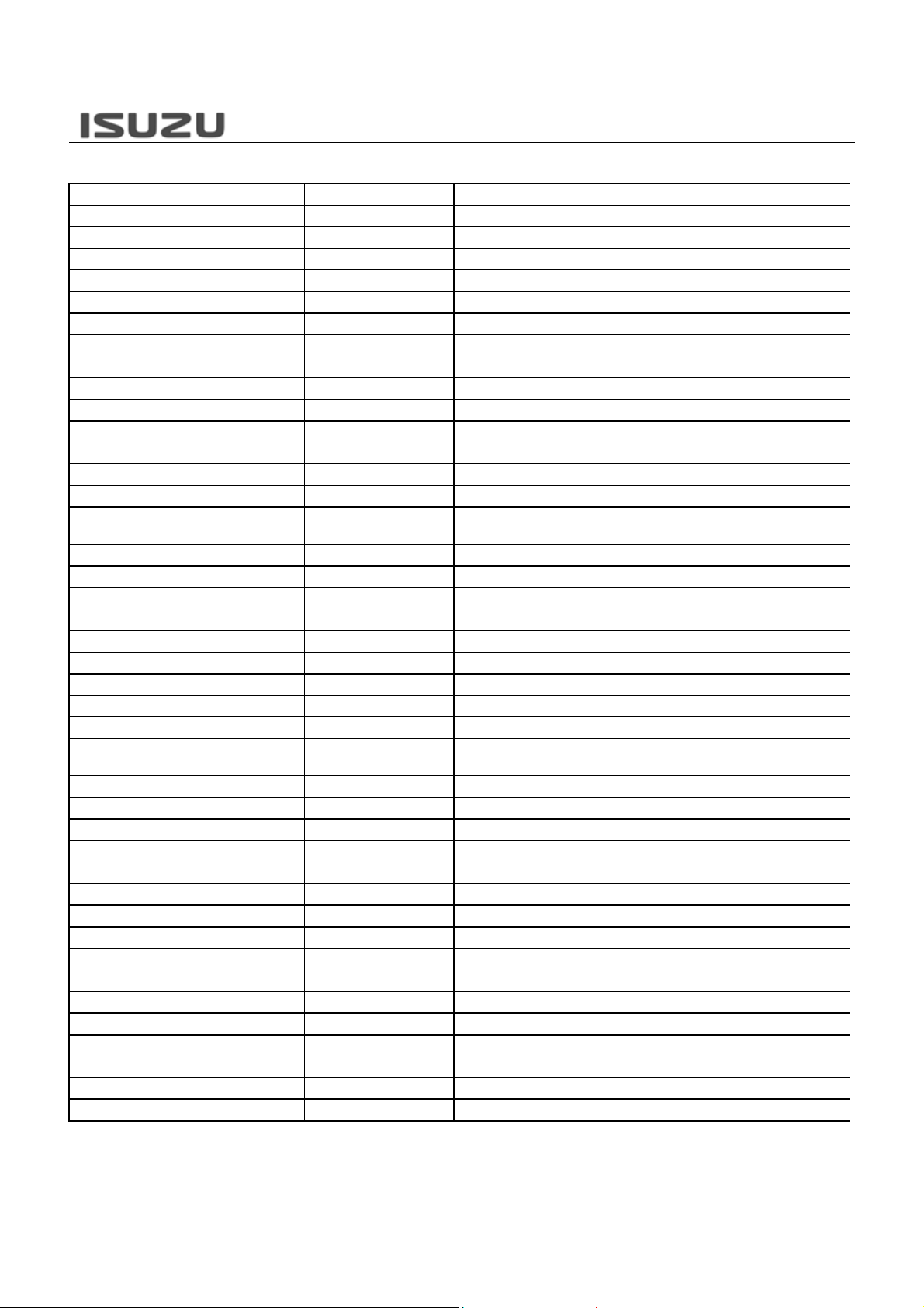
Part Status Description or Reason in Comparison with 4HE1-TC Engine
Cylinder Block Change Bore size is upped (110mm to 115mm / 4.33in to 4.53in)
Crankshaft Carry-over Cylinder Head Change Four valve type with camshaft position sensor hole
Cylinder Head Gasket Change Cylinder head is changed
Camshaft Change Four valve type is employed
Camshaft Gear Change Scissors gear type is employed
Inlet Valve Change Four valve type is employed
Exhaust Valve Change Four valve type is employed
Valve Spring Change Four valve type is employed
Rocker Arm Cha nge Four valve type is employed
Cylinder Head Cover Change Four valve type is employed
Timing Gear T rain Change Fuel system is changed
Flywheel Change Crankshaft position sensor is ring added
Flex Plate Carry-over —
Flywheel Housing Change
Engine Hanger Change Cylinder head and EGR layout is changed
Piston Change Bore size is upped
Piston Ring Change Bore size is upped
Connecting Rod Carry-over Oil Pan Change Oil level switch is added
Oil Pump Carry-over Oil Cooler Change Engine size is changed
Front Cover Carry-over Water Pump Carry-over —
Cooling Fan
EGR Cooler New Newly adopted
EGR Pipe Change EGR layout is changed
EGR Valve Change Electrical control type
PCV System Carry-over Fuel Pump Change Common rail system is employed (supply pump)
Injection Nozzle Change Common rail system is employed
Injection Pipe Change Common rail system is employed
Fuel Pipe Change Common rail system is employed
Intake Duct Change Layout is changed & boost pressure sensor are added
Intake Manifold Change Layout is changed
Intercooler Change Size is upped
Exhaust Manifold Carry-over Turbocharger Change Wastegate valve actuator setting is changed
ACG Change
Starter Carry-over Engine Harness Change Common rail system is employed
Change (4HK1-TCS)
Carry-over (4HK1-TCN)
Major mechanical changed items are listed below.
Common rail system is employed & crankshaft position sensor
hole
4HK1-TCS: Size is changed to improve performance

N*R 4HK1-TC Engine-3
ENGINE MAIN DATA & SPECIFICATIONS
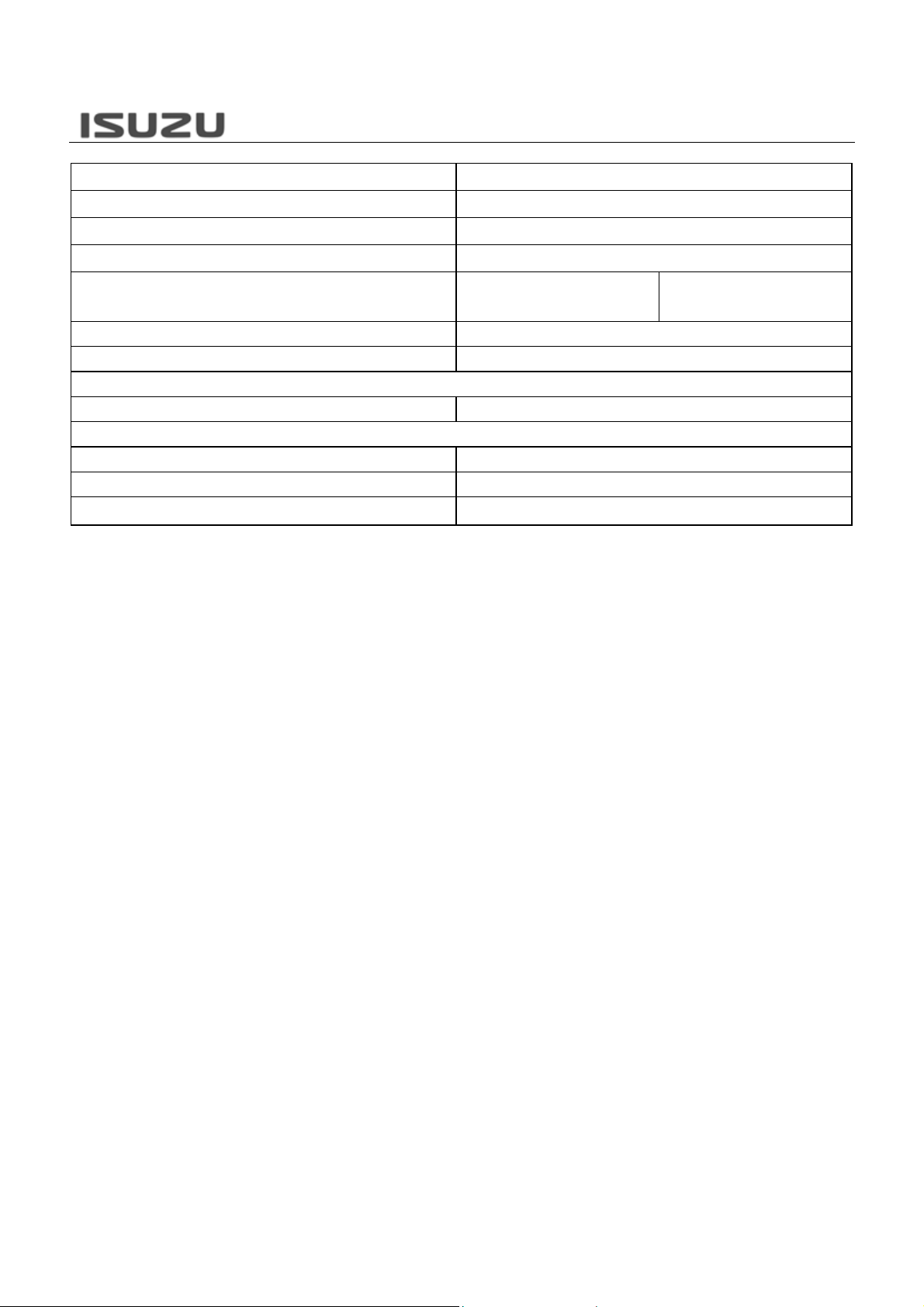
Engine Model 4HE1-TC 4HK1-TC
Engine Type Diesel, Four Cycle
Cylinder Layout — Number of Cylinders Inline-Four Cylinders
Fuel Injection Order 1-3-4-2
Bore x Stroke (mm/in) 110.0 x 125.0 / 4.33 x 4.92 115.0 x 125.0 / 4.53 x 4.92
Total Displacement (cc) 4751 5193
Compression Ratio 18.0 18.5
Compression Pressure at 200 rpm (MPa / psi) 3.0 / 441 3.3 / 478
Combustion Camber Type Direct Injection
Cylinder Liner Dry Type
Idle Speed (rpm) 800±25 650±25
Fuel System Mechanical Type Governor Common Rail System
Injection Pump Type BOSCH In-line Type (MITICS) DENSO (HP3) Supply Pump
Injection Nozzle Type Hole Nozzle (Mechanical Type)
Number of Injection Hole 6 7
Electrical Controlled Injector
(G2)
Diameter of Injection Hole (mm) 0.21 0.16
Injection Nozzle Operating Pressure (MPa) 17.65 Electrically Controlled
Fuel Filter Type Cartridge Paper Element & Water Separator
Valve System
Valve Layout Overhead Valve
Drive Type Gear Drive
Intake Valve Open At BTDC (deg) 14.0 19.0
Intake Valve Close At ABDC (deg) 51.0 53.0
Exhaust Valve Open At BBDC (deg) 49.0 48.0
Exhaust Valve Close At ATDC (deg) 16.0 14.0
Intake Valve Clearance At Cold (mm) 0.4
Exhaust Valve Clearance At Cold (mm) 0.4
Cooling System
Cooling Method Water Cooled
Water Capacity (litter/gal) 14 (3.7)
Water Pump Type Centrifugal Impeller Type
Thermostat Type Wax Pellet
Thermostat Opening Temperature (deg. C / deg. F) 82 & 85 / 180 & 185
Lubricating System
Lubricating Method Full Flow Pressure Circulation
Oil Pump Type Gear
Oil Capacity (litter/gal) 13 (3.4)
Oil Filter Type Cartridge Paper Element
Air Cleaner Type Dry Paper Element
N*R 4HK1-TC Engine-4
EGR System
PCV System Open Type
Preheating System Glow Plug
Starting System
Starter Motor Output (V-kW) 24 — 3.0
Charge System
Alternator Output (V-A) 24 – 50, 60 or 80
Regulator Type IC
Battery Size 115E41R x 2
W/O Cooler & Vacuum Control
EGR Valve
W/Cooler & Electrical Control
EGR Valve
N*R 4HK1-TC Engine-5
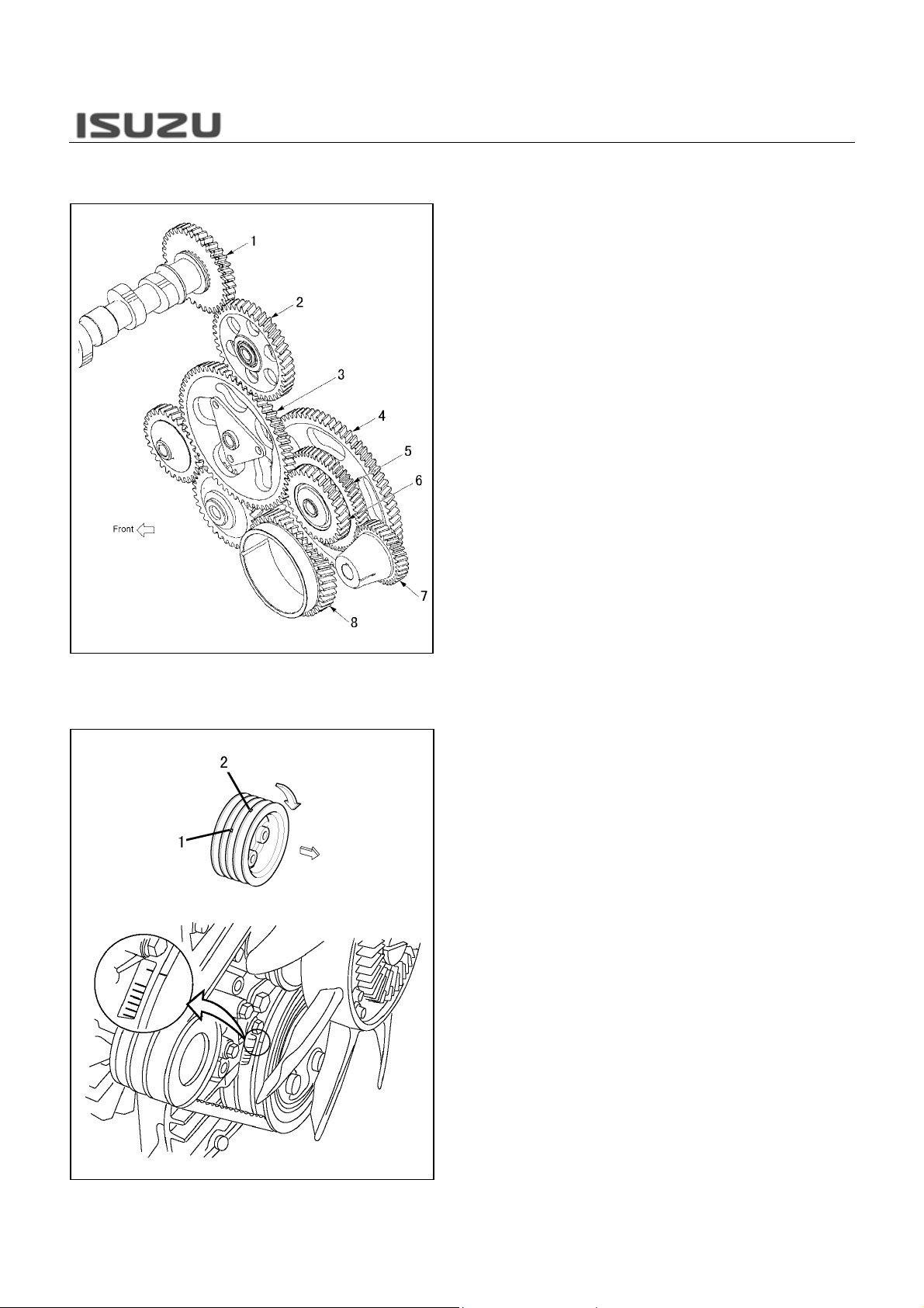
GEAR TRAIN
Valve Train
To rotate the fuel supply pump wit h engine speed, idle
gear has changed with three steps. The crankshaft
gear (42 teeth) correspon ds with the large diameter o
idle gear A (72 teeth). The fuel s upply pump gear (35
teeth) corresponds with the middle diameter of idle
gear A (60 teeth). The idle gear B (61 teeth)
corresponds with the small diamet er of idle gear A (30
teeth).
1. Camshaft Gear (Z=35)
2. Idle Gear C (Z=41)
3. Idle Gear B (Z=61)
4. Idle Gear A (Large) (Z=72)
5. Idle Gear A (Middle) (Z=60)
6. Idle Gear A (Small) (Z=30)
7. Fuel Supply Pump Gear (Z=35)
8. Crankshaft Gear (Z=42)
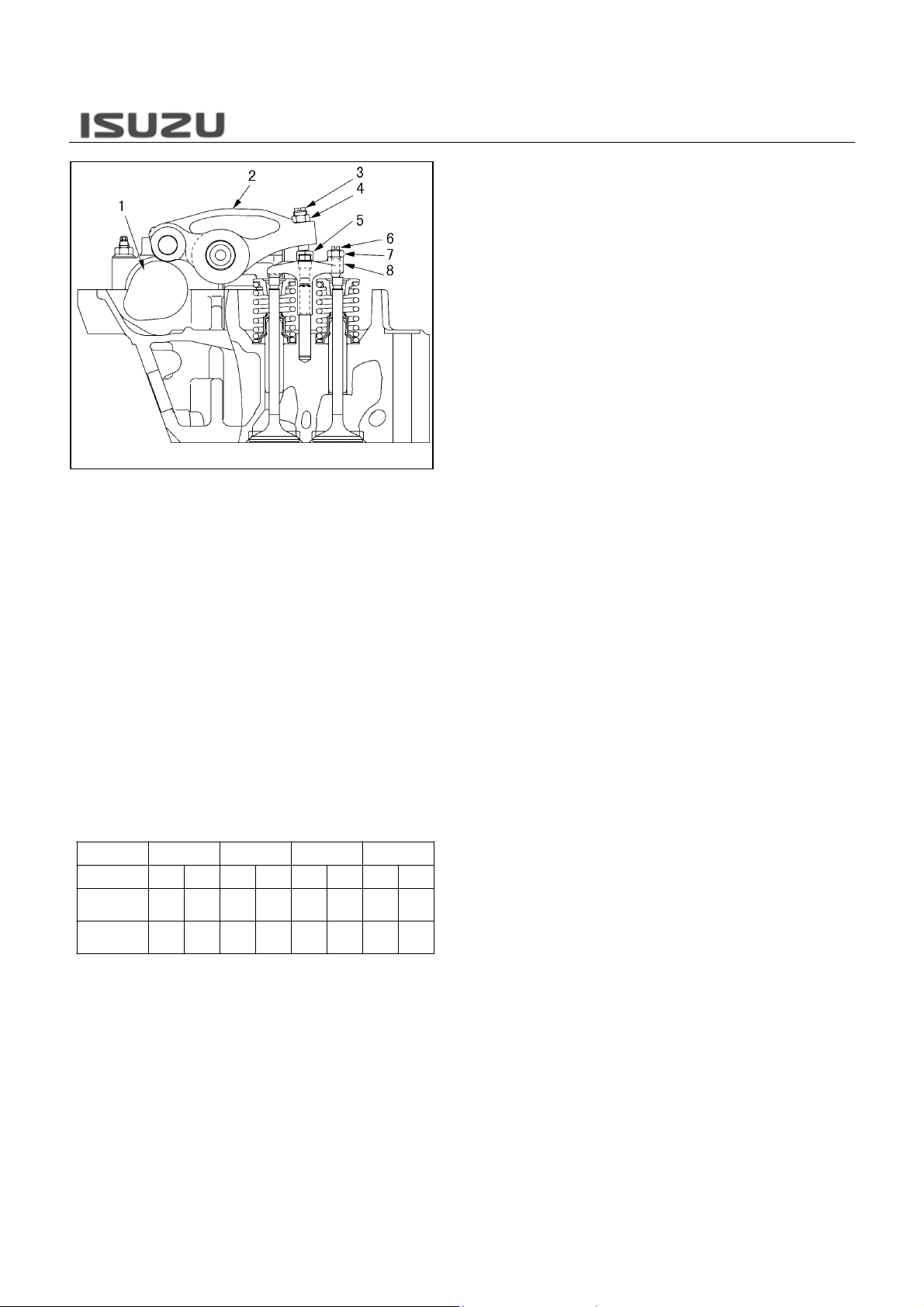
To improve exhaust emission and engine output
performance, four valve mechanism is newly adopted
for 4HK1-TC engine. Note that the adjustm ent method
of valve clearance has been changed from 4HK1-TC
engine as following steps.
1. Rotate the crankshaft to make the No.1 cylinder meet
the compression top dead center (TDC). There are 2
marks stamped on the crank pulley. The mark (1) is
used to bring the engine No.1 or No. 4 cylinder to TDC .
The mark (2) is irrelevant. Do not use the mark (2).
Cylinder No.1234
Valve INEXINEXINEXINEX
No.1 Cylinder
Compression
TDC
No.4 Cylinder
Compression
TDC
OOO O
XX XX
N*R 4HK1-TC Engine-6
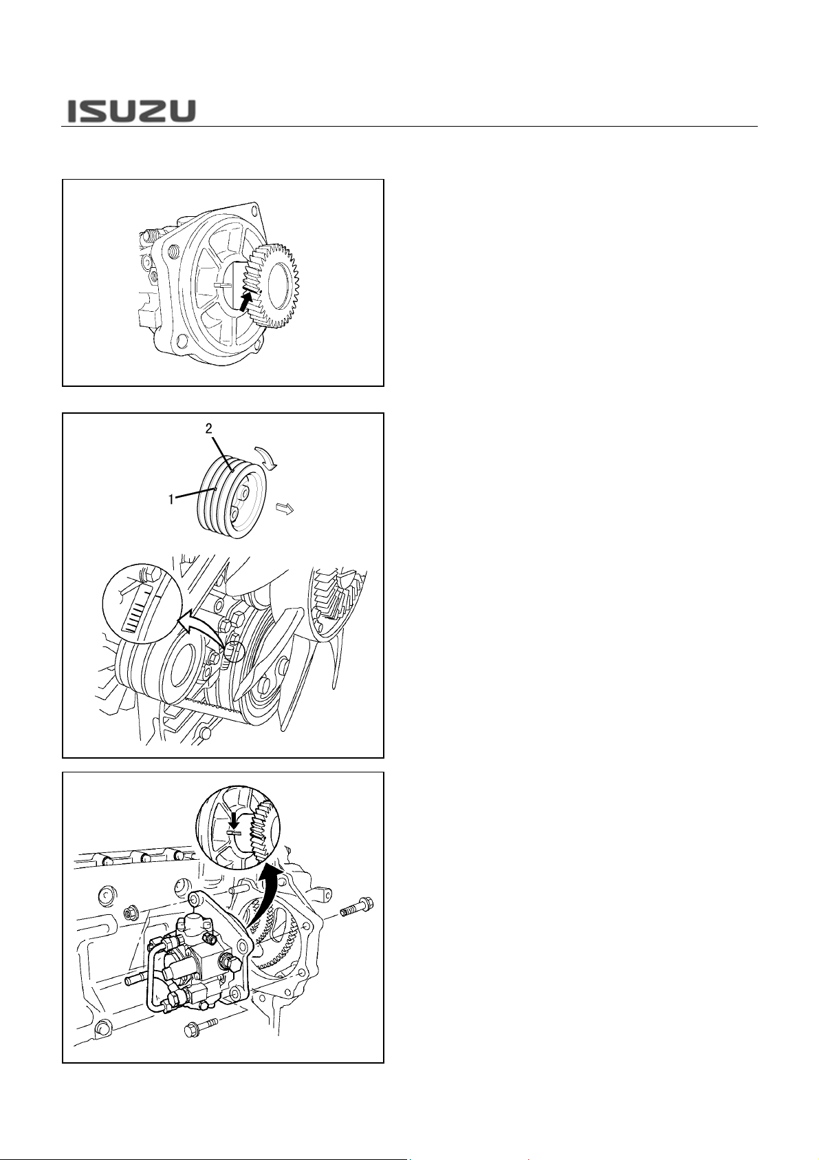
2. Loosen fully each adjusting screw (8) & (2) of the bridge
and the rocker arm.
3. Insert a 0.4mm (0.016in) thickness gauge between the
tip of the rocker arm and bridge cap (5), and adjust the
clearance with the adjusting screw (3) on the rocke
arm, and then fix it with a lock nut (4).
4. With a thickness gauge kept inserted, check that the
adjusting screw (6) contacts the valve shaft end and the
movement of the thickness gauge has become tight
when the adjusting screw (6) on the bridge is tightened
lightly.
5. Check the valve shaft end on the opposite side floats o
it contacts obliquely. In case of a floating or oblique
contact, loosen a little the adjusting screw (6) on the
bridge side and adjust so that the valve shaft ends on
both sides get in contact properly. Bridge (8) & valve
shaft end clearance less than 0.1 mm (0.004in).
6. After the adjustment so that the end of the valves on
both sides touch properly, tighten up the lock nut (7) on
the bridge (8).
Note that unless the bridge is kept hor izontal, t he bridge
is pressed obliquely, thus cau sing the bridge a nd bridge
guide to be seized or damaged. Therefore, exact
adjustment is required.
Valve clearance: 0.4mm (0.016in) intake & exhaust
side at cold
Adjusting screw lock nut tightening torque: 22Nm
(16lb ft)
At the No.1 cylinder compression top dead center, the
valves with “O” mark in the following table, or at the
No.4 cylinder compression top dead center, the valve
with “X“ mark can be adjusted.
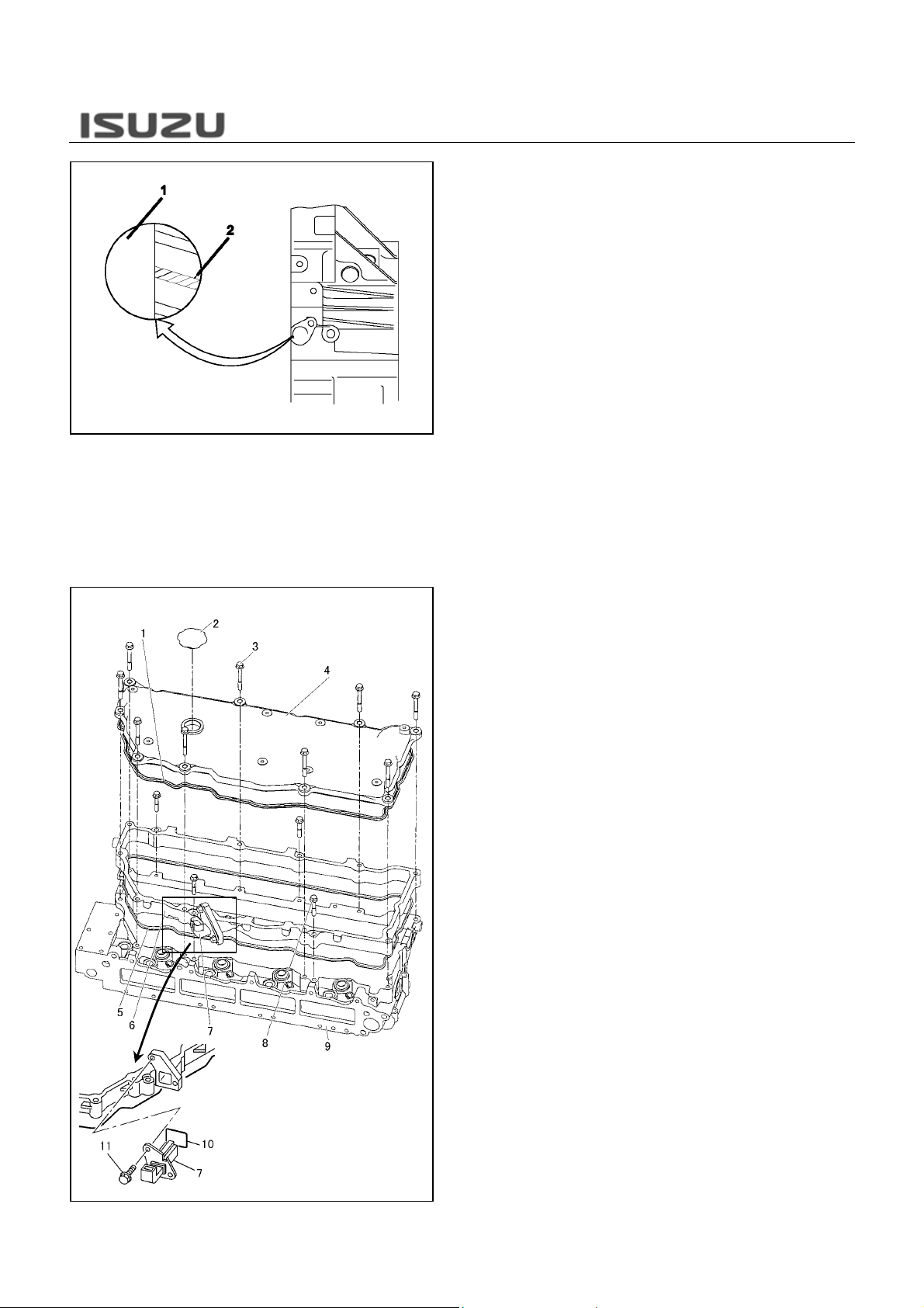
Fuel Supply Pump Installation
N*R 4HK1-TC Engine-7
1. Apply white paint to the top of the fuel supply pump gear
tooth directly above the stamped “O” mark.
2. Rotate the crankshaft to the compression top dead
center (TDC). There are 2 marks stamped on th e crank
pulley. The mark (1) is used to b ring th e engin e No.1 o
No. 4 cylinder to TDC. The mark (2) is irrelevant. Do not
use the mark (2).
3. Install the O-ring to the fuel supply pump.
4. Align a slit of the fuel supply pump bracket with a white
paint on the gear and install the fuel supply pump in the
gear case using the stud bolts as a guide.
CYLINDER HEAD COVER & HEAD COVER
CASE
N*R 4HK1-TC Engine-8
5. Check through the hole (1) that a white paint (2) on the
gear is in the position shown on the left.
Fixing nut tightening torque: 50Nm (37lb ft)
Fixing bolt tightening torque: 76Nm (56lb ft)
long with the employment of a common rail type f uel
injection system, the head cover is split and housed in a
newly introduced head cover case attached with an
intermediate connector for th e injector. The head cove
case is so designed that it is secured indi vidually to the
cylinder head with four bolts, and further it is tightened
together with the head cover with nine bolts.
Accordingly, the head cover is removable individually
regardless of the injector harness, thus enabling easy
inspection and service including the valve clearance
adjustment.
1. Gasket
2. Oil Filler Cap
3. Head Cover Bolt
4. Head Cover
5. Gasket
6. Head Cover Case
7. Intermediate Harness Connector
8. Cylinder Head Cover Case Bolt
9. Cylinder Head
10. Gasket
11. Connector Fixing Bolt
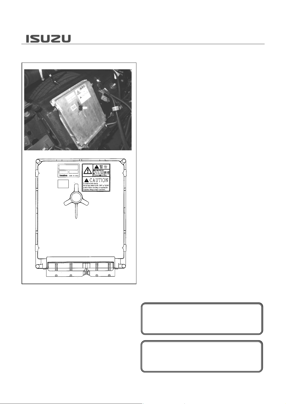
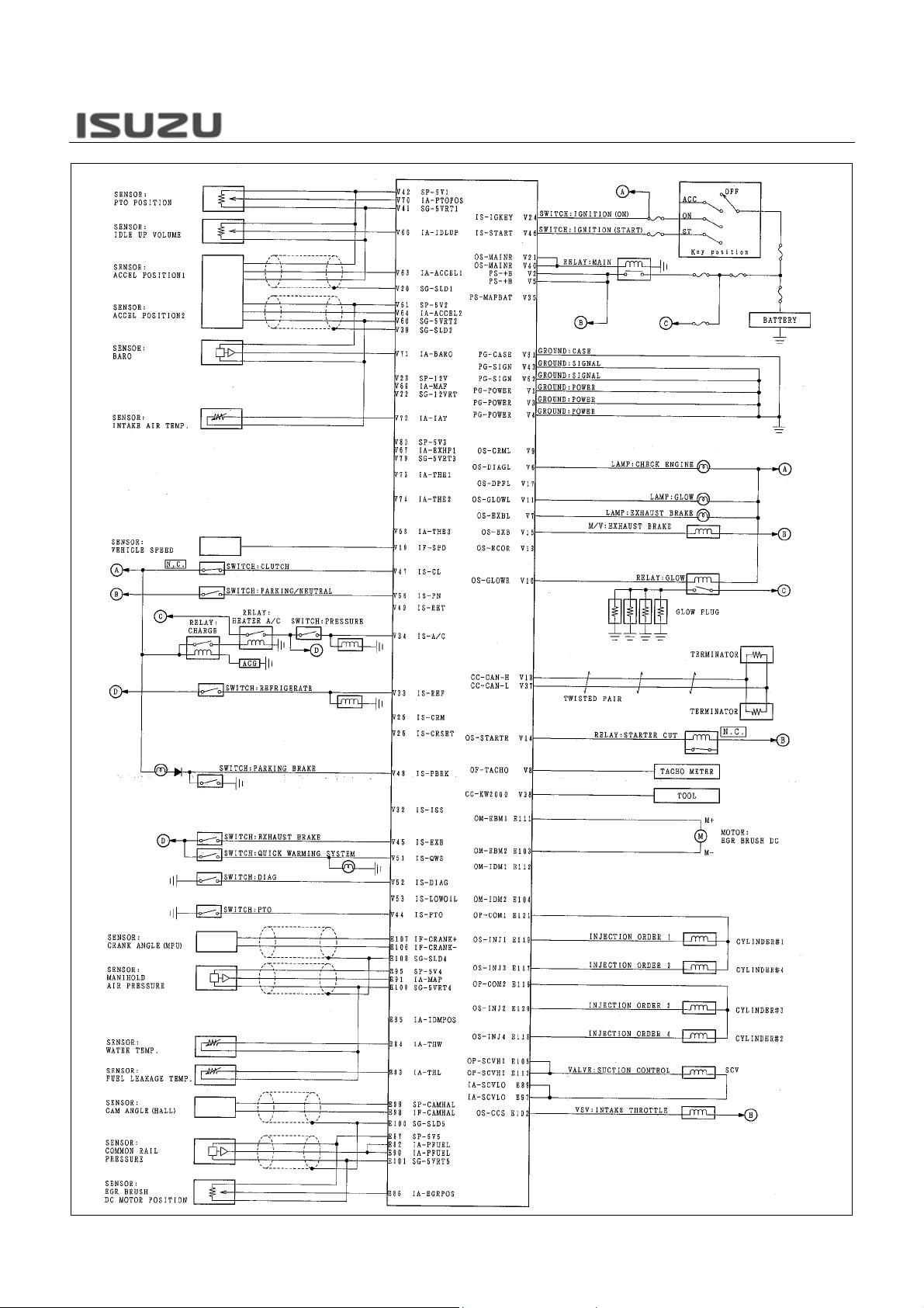
ENGINE CONTROL MODULE (ECM)
N*R 4HK1-TC Engine-9
The engine control module (ECM) is located at inside o
engine-side cover on the left via mounting bracket and
is beside the engine. The ECM is made by Transtron.
The ECM mainly controls the following.
Fuel injection control
Fuel timing control
Exhaust gas recirculation (EGR) system control
Preheating system control
Exhaust brake control
Power take off (PTO) control
On-board diagnostics for engine control
The ECM constantly observes the information from
various sensors. The ECM controls the systems that
affect vehicle performance. The ECM performs the
diagnostic function of the system. The ECM can
recognize operational problems, alert the driver through
the malfunction indicator lamp (MIL), and store
diagnostic trouble code (DTC). DTC identify the syst em
faults to aid the technician in making repair.
This diagnostic applies to internal microprocesso
integrity conditions within the ECM. The electronically
erasable programmable read only memory (EEPROM)
memorize learning data and injector ID code data fo
engine control and communication with other control
module.
Symbol “!” warns you of an electric shock haza rd. To avoid
shock and possible serious injury, DO NOT touch the
terminals. When disconnecting the harness connector,
always turn OFF the ignition switch or disconnect the
battery cable.
Parts number of each ECM mainly differs with following
contents.
Engine specification (output or torque)
Transmission specification (MYY, MZZ or Smoother)
Speed limiter application
Notice!
If the ECM is to be replaced the fuel injector ID
Code Data (24, 0-9 or A-F characters for each fuel
injector) MUST be programmed into the new ECM.
Notice!
This ECM does not have ability of re-flash function
by Service Programming System (SPS) via Tech 2
scan tool.
N*R 4HK1-TC Engine-10
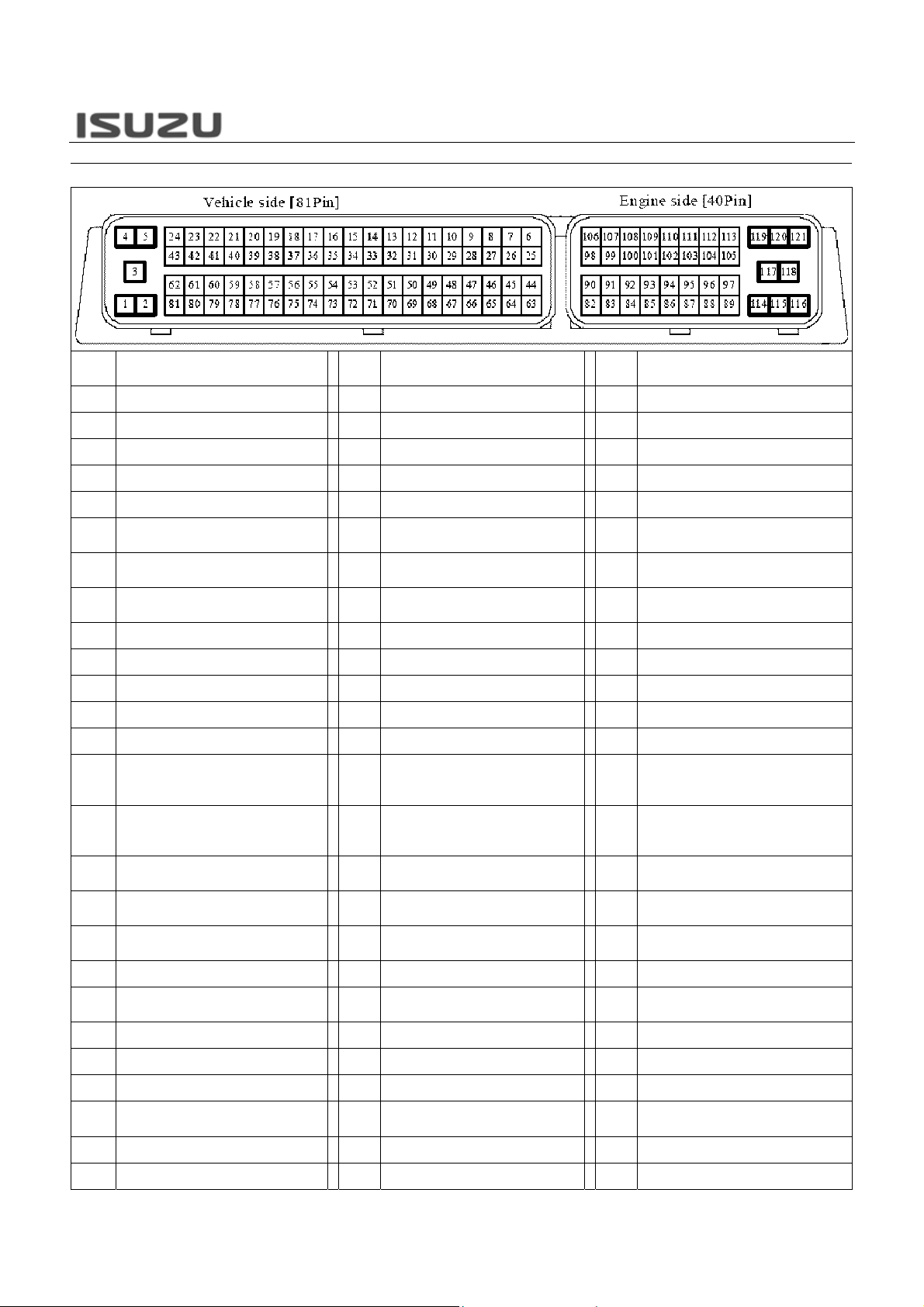
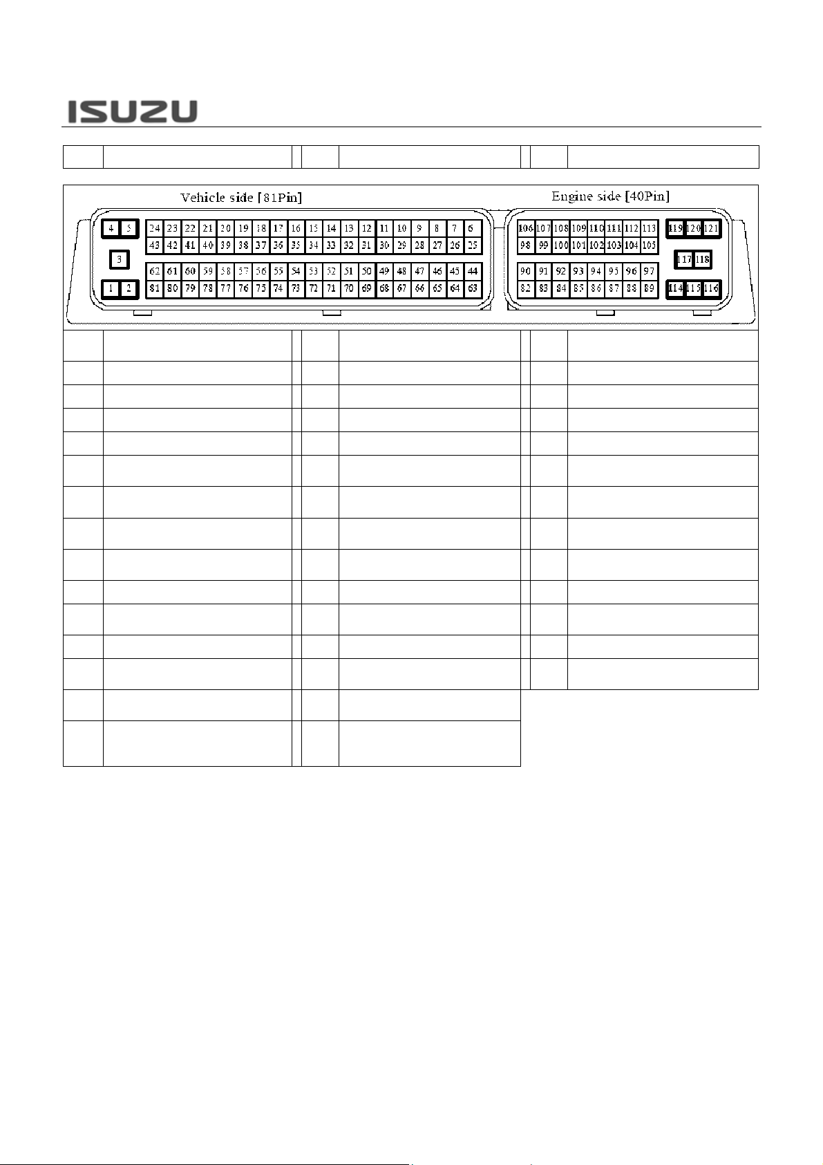
ECM Connector Pin Assignment
N*R 4HK1-TC Engine-11
Pin No. Pin Function
1 ECM Power Ground 28 Not Used 55 Not Used
2 Main Relay Voltage 29 Not Used 56 Not Used
3 ECM Power Ground 30 Not Used 57 Not Used
4 ECM Power Ground 31 Not Used 58 Not Used
5 Main Relay Voltage 32 Not Used 59 Not Used
Malfunction Indicator Lamp (MIL)
6
Control
7 Exhaust Brake Lamp Control 34 A/C Switch Input Signal 61
Engine Speed Signal Output to
8
IPC
9 Not Used 36 Not Used 63 APP Sensor 1 Input Signal
10 Glow Plug Relay Control 37 CAN Low Signal 64 APP Sensor 2 Input Signal
11 Glow Indicator Lamp Control 38 Keyword 2000 Serial Data 65 Not Used
12 Not Used 39 APP Sensor 2 Shield 66 Idle Up Sensor Input Signal
13 Not Used 40 Main Relay Power Supply 67 Not Used
14 Starter Cut Relay Control 41
15 Exhaust Brake Solenoid Control 42
16 Not Used 43 ECM Signal Ground 70
17 Not Used 44
18 CAN High Signal 45
19 VSS Input Signal 46 Start Position Input Signal 73 Not Used
20 APP Sensor 1 Shield 47
21 Main Relay Power Supply 48 Park Brake Switch Input Signal 75 Not Used
22 Not Used 49 Not Used 76 Not Used
23 Not Used 50 Neutral Switch Input Signal 77 Not Used
24 Ignition ON Switch Input Signal 51
25 Not Used 52 Diag Switch 79 Not Used
26 Not Used 53 Not Used 80 Not Used
Pin
No.
33 Refrigerator Switch Input Signal 60
35 Not Used 62 ECM Signal Ground
APP Sensor 1, Idle Up Sensor,
Remote PTO Accelerator
Sensor Low Reference
APP Sensor 1, Idle Up Sensor,
Remote PTO Accelerator
Sensor 5V Reference
PTO Operation Switch Input
Signal
Exhaust Brake Switch Input
Signal
Clutch Switch Input Signal (M/T
Only)
Engine Warm Up Switch Input
Signal
Pin Function
Pin
No.
APP Sensor 2, BARO Sensor, IAT
Sensor Low Reference
APP Sensor 2, BARO Sensor, IAT
Sensor 5V Reference
68 Not Used
69 Not Used
Remote PTO Accelerator Sensor
Input Signal
71 BARO Sensor Input Signal
72 IAT Sensor Input Signal
74 Not Used
78 Not Used
Pin Function
27 Not Used 54 Not Used 81 ECM Case Ground
N*R 4HK1-TC Engine-12
Pin No. Pin Function
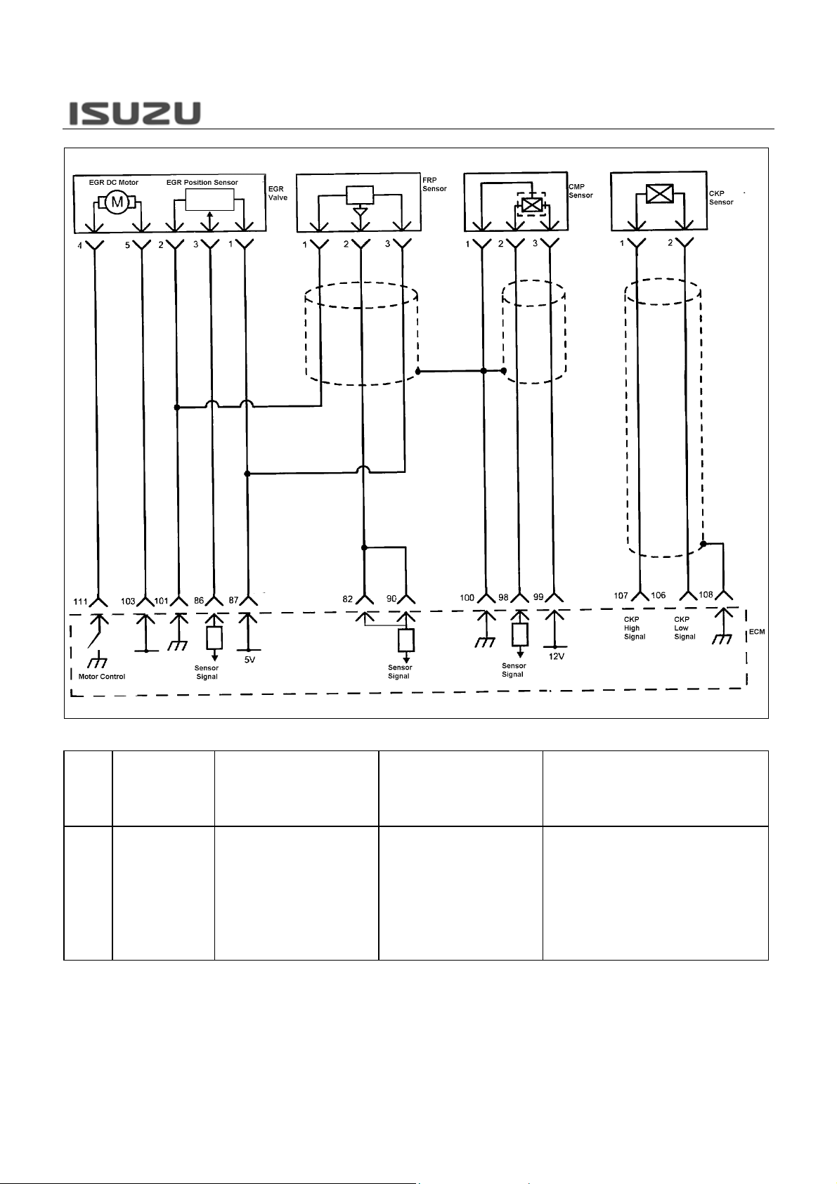
82 FRP Sensor Input Signal 96 Not Used 110 Not Used
83 FT Sensor Input Signal 97 SCV Low Control 111 EGR Valve DC Motor Control
84 ECT Sensor Input Signal 98 CMP Sensor 12V Reference 112 Not Used
85 Not Used 99 CMP Sensor Input Signal 113 SCV High Control
EGR Valve Position Sensor Input
86
Signal
FRP Sensor, EGR Valve Position
87
Sensor Input Signal
88 Not Used 102
89 SCV Low Control 103
90 FRP Sensor Input Signal 104 Not Used 118 Cylinder #2 Injector Control
Boost Pressure Sensor Input
91
Signal
92 Not Used 106 CKP Sensor Low Signal Input 120 Cylinder #3 Injector Control
93 Not Used 107 CKP Sensor High Signal Input 121
94 Not Used 108
Boost Pressure Sensor 5V
95
Reference
Pin
No.
100
101
105 SCV High Control 119 Cylinder #1 Injector Control
109
FRP Sensor, CMP Sensor
Shield
FRP Sensor, EGR Valve
Position Sensor Low Reference
Intake Throttle Solenoid Valve
Control
EGR Valve DC Motor Power
Supply
Boost Pressure Sensor, CKP
Sensor Shield
Boost Pressure Sensor, ECT
Sensor, FT Sensor Low
Reference
Pin Function
Pin
No.
114 Not Used
115 Not Used
Cylinder #2, #3 Injector Power
116
Supply
117 Cylinder #4 Injector Control
Cylinder #1, #4 Injector Power
Supply
Pin Function
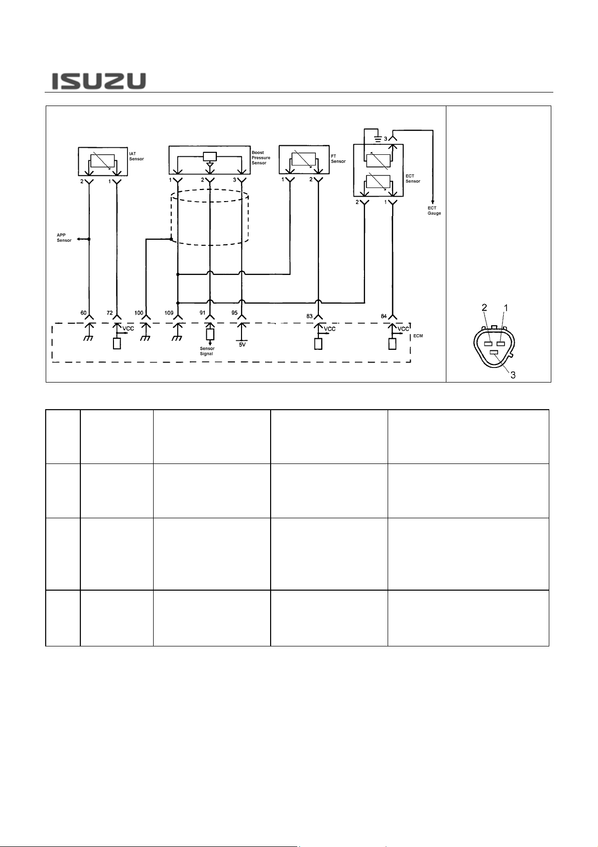
ECM Inputs & Outputs
Sensor Input
Crankshaft position (CKP) sensor
•
• Camshaft position (CMP) sensor
Intake air temperature (IAT) sensor
•
• Engine coolant temperature (ECT) sensor
Fuel temperature (FT) sensor
•
• Fuel rail pressure (FRP) sensor
Barometric pressure (BARO) sensor
•
• Boost pressure sensor
Accelerator pedal position (APP) sensor
•
• Vehicle speed sensor (VSS)
EGR valve position sensor
•
• Idle up control sensor
Remote PTO accelerator sensor
•
Switch Input
• Ignition switch (ON/start position)
Clutch switch (M/T)
•
• Park brake switch
Park/Neutral switch
•
• Exhaust brake switch
Engine warm up switch
•
• A/C switch
PTO switch
•
• Refrigerator switch
Diag request switch
•
EC
M
N*R 4HK1-TC Engine-13
Fuel Injection Control Output
• Suction control valve (SCV)
Fuel injector #1
•
• Fuel injector #2
Fuel injector #3
•
• Fuel injector #4
ctuator Control Output
• Intake throttle solenoid valve
Exhaust brake solenoid valve
•
• EGR valve motor
Relay & Lamp Control Output
Glow relay
•
• Starter cut relay
Malfunction indicator lamp (MIL)
•
• Glow indicator lamp
Exhaust brake indicator lamp
•
Communication
Tech 2 (Keyword 2000)
•
• Controller area network (CAN)
N*R 4HK1-TC Engine-14
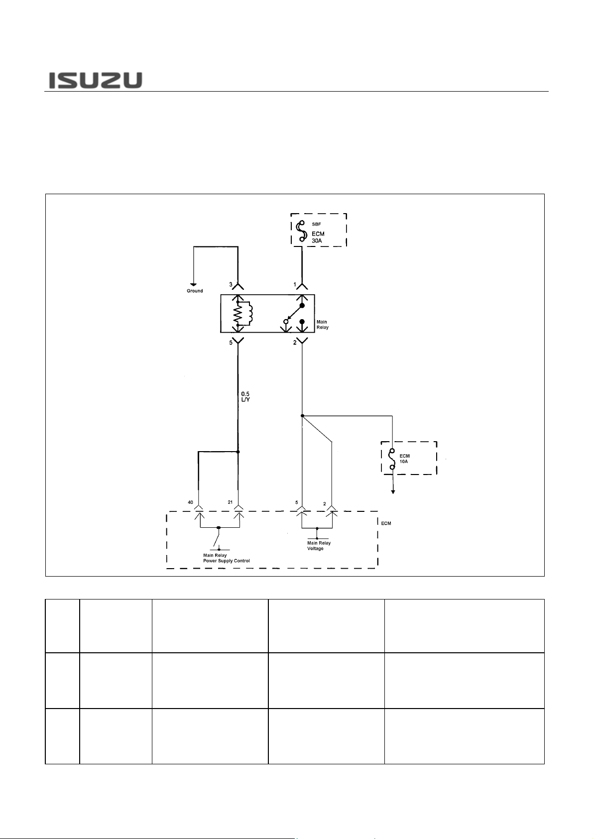
The ECM monitors the battery voltage through the ECM
main relay load supply voltage terminals “2” and “5”,
and the ignition voltage on the ignition voltage feed
terminal “24” to make sure that t he voltage stays within
the proper range. When the char ging system detects a
malfunction, the charge indicator will light.
Related DTC
DTC
DTC Name On Scan
P1625 ECM Main Relay
P1625 ECM Main Relay
Tool
Circuit
Circuit
Condition for Running the DTC Condition for Setting the DTC Suspected Cause
DTC P1603 is not set.
The ignition switch is ON.
The ignition switch ON time is
longer than 3 seconds.
The ignition switch is OFF.
The ECM detects that a low
voltage condition on the ECM
main relay voltage feed circuit for
longer than 3 seconds when the
ECM main relay is commanded
ON.
The ECM detects that a high
voltage condition on the ECM
main relay voltage feed circuit for
longer than 5 seconds when the
ECM main relay is commanded
OFF.
ECM main relay coil side power supply circuit is
open circuit or high resistance.
ECM main relay voltage feed circuit is open
circuit or high resistance.
Faulty ECM main relay.
ECM main relay coil side power supply circuit is
short to battery voltage circuit.
ECM main relay voltage feed circuit is short to
battery voltage circuit.
Faulty ECM main relay.

N*R 4HK1-TC Engine-15
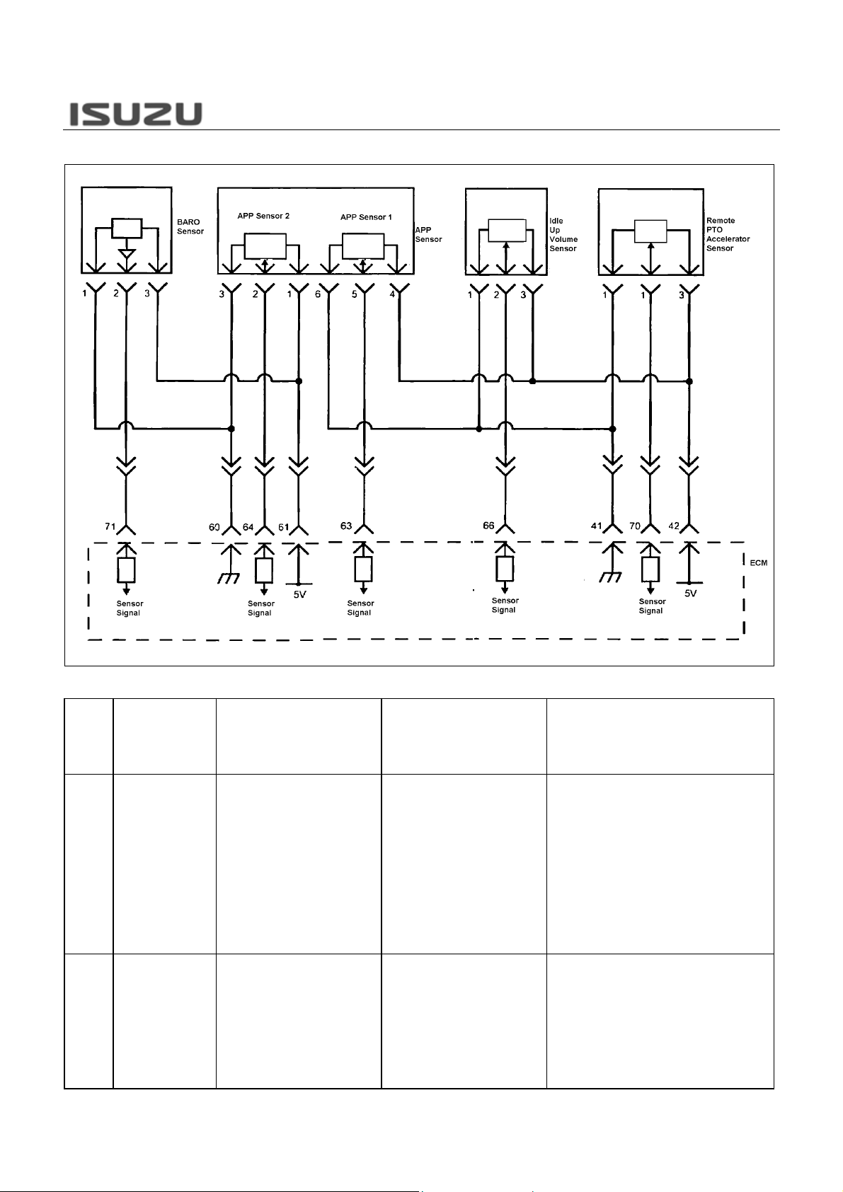
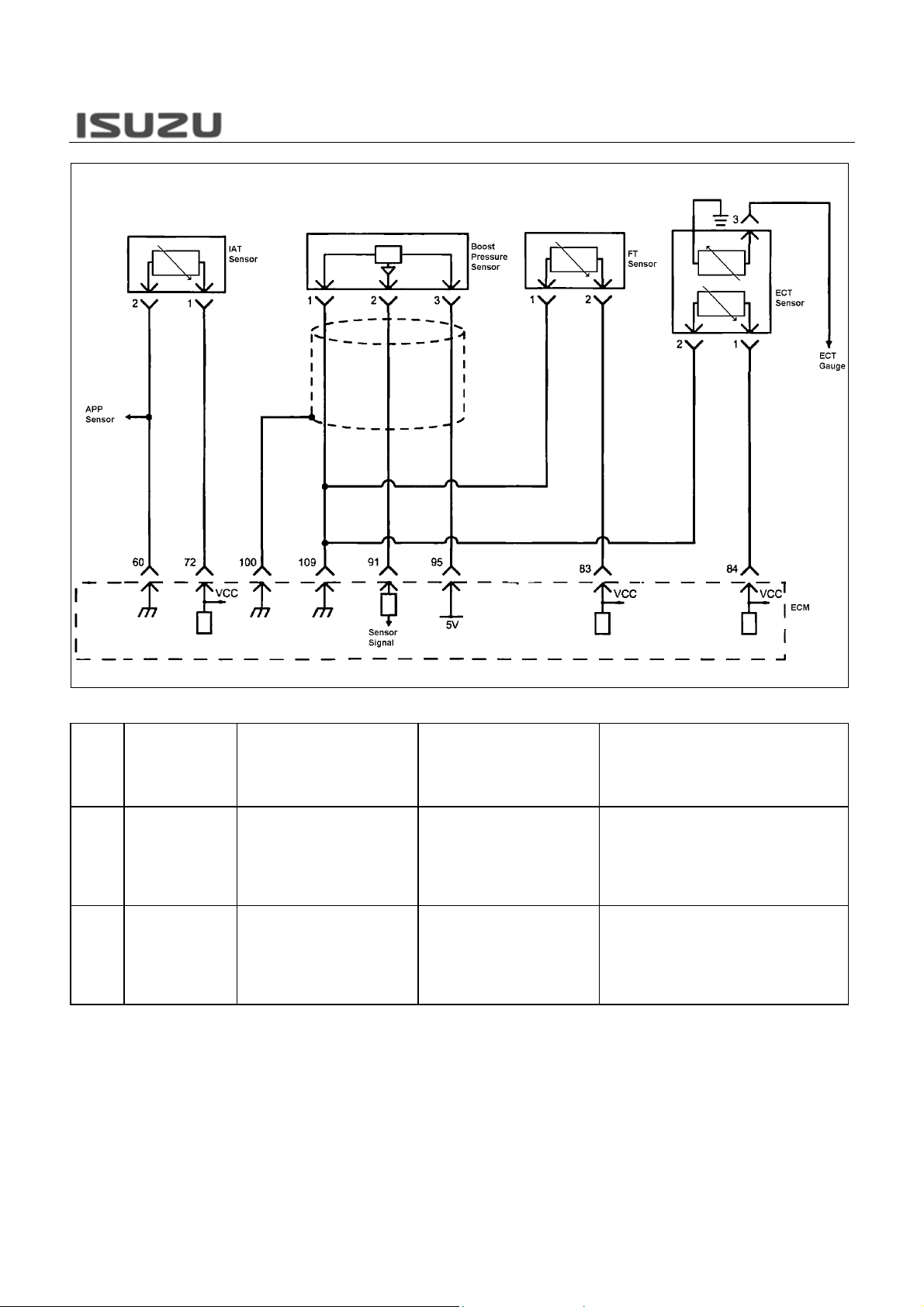
The engine control module (ECM) provides 5volts
reference voltage through the refer ence circuit 1, 2, 3, 4
and 5 to the following sensors.
5volts reference circuit 1
Accelerator pedal position (APP) sensor 1
Idle up volume sensor
Remote PTO accelerator sensor
5volts reference circuit 2
APP sensor 2
Barometric pressure (BARO) sensor
5volts reference circuit 3 (Not Used)
5volts reference circuit 4
Boost pressure sensor
5volts reference circuit 5
Fuel rail pressure (FRP) sensor
EGR valve position sensor
N*R 4HK1-TC Engine-16
Related DTC
DTC
DTC Name On Scan
P1631 5 Volt Reference
P1632 5 Volt Reference
Tool
Circuit 1
Circuit 2
Condition for Running the DTC Condition for Setting the DTC Suspected Cause
DTC P1630 is not set.
The battery voltage is between 16
– 32 volts.
The ignition switch is ON.
DTC P1630 is not set.
The battery voltage is between 16
– 32 volts.
The ignition switch is ON.
The ECM detects that the 5 volts
reference circuit 1 voltage is less
than 4.5 volts.
OR
The ECM detects that the 5 volts
reference circuit 1 voltage is more
than 5.5 volts.
The ECM detects that the 5 volts
reference circuit 2 voltage is less
than 4.5 volts.
OR
The ECM detects that the 5 volts
reference circuit 2 voltage is more
than 5.5 volts.
APP sensor 1 5V reference circuit is short to
ground, short to any 12V reference circuit, short
to battery or ignition voltage circuit.
Idle up sensor 5V reference circuit is short to
ground, short to any 12V reference circuit, short
to battery or ignition voltage circuit.
PTO accelerator sensor 5V reference circuit is
short to ground, short to any 12V reference
circuit, short to battery or ignition voltage circuit.
Faulty APP sensor 1.
Faulty Idle up sensor.
Faulty PTO accelerator sensor.
Faulty ECM.
Notice: APP sensor 1 is internal to APP sensor
assembly.
APP sensor 2 5V reference circuit is short to
ground, short to any 12V reference circuit, short
to battery or ignition voltage circuit.
BARO sensor 5V reference circuit is short to
ground, short to any 12V reference circuit, short
to battery or ignition voltage circuit.
Faulty APP sensor 2.
Faulty BARO sensor.
Faulty ECM.
Notice: APP sensor 2 is internal to APP sensor
assembly.
N*R 4HK1-TC Engine-17
Related DTC
DTC
DTC Name On Scan
P1633 5 Volt Reference
P1634 5 Volt Reference
Tool
Circuit 3
Circuit 4
Condition for Running the DTC Condition for Setting the DTC Suspected Cause
DTC P1630 is not set.
The battery voltage is between 16
– 32 volts.
The ignition switch is ON.
DTC P1630 is not set.
The battery voltage is between 16
– 32 volts.
The ignition switch is ON.
The ECM detects that the 5 volts
reference circuit 3 voltage is less
than 4.5 volts.
OR
The ECM detects that the 5 volts
reference circuit 3 voltage is more
than 5.5 volts.
The ECM detects that the 5 volts
reference circuit 4 voltage is less
than 4.5 volts.
OR
The ECM detects that the 5 volts
reference circuit 4 voltage is more
than 5.5 volts.
Boost pressure sensor 5V reference circuit is
short to ground, short to any 12V reference
circuit, short to battery or ignition voltage circuit.
Faulty boost pressure sensor.
Faulty ECM.
—
N*R 4HK1-TC Engine-18
Related DTC
DTC
DTC Name On Scan
P1635 5 Volt Reference
Tool
Circuit 5
Condition for Running the DTC Condition for Setting the DTC Suspected Cause
DTC P1630 is not set.
The battery voltage is between 16
– 32 volts.
The ignition switch is ON.
The ECM detects that the 5 volts
reference circuit 5 voltage is less
than 4.5 volts.
OR
The ECM detects that the 5 volts
reference circuit 5 voltage is more
than 5.5 volts.
FRP sensor 5V reference circuit is short to
ground, short to any 12V reference circuit, short
to battery or ignition voltage circuit.
EGR valve position sensor 5V reference circuit is
short to ground, short to any 12V reference
circuit, short to battery or ignition voltage circuit.
Faulty FRP sensor.
Faulty EGR valve position sensor.
Faulty ECM.
Notice: EGR valve position sensor is internal to
EGR valve assembly.
N*R 4HK1-TC Engine-19
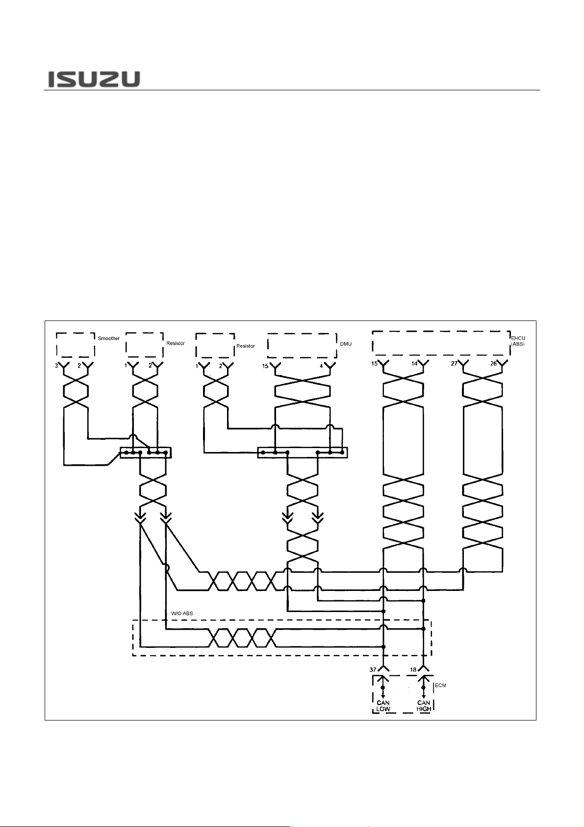
The engine control module (ECM), the smoother control
module, ABS control module (EHCU) and the DMU,
interchange of data among each contr oller per formed via a
controller area network (CAN) communication bus.
Following signals are communicated via a CAN bus.
• Accelerator pedal position signal
Engine output torque
•
• PTO control signal
Exhaust brake cut signal
•
• Engine speed signal
Injection volume reduction signal
•
The ECM monitors CAN operational status by expecting a
constant flow of messages from each module. If the ECM
fails to receive an expected message from each module,
DTC U2104, U2106 or U2108 will set depending on what
communication is lost.

Related DTC
DTC
DTC Name On Scan
Tool
Condition for Running the DTC Condition for Setting the DTC Suspected Cause
N*R 4HK1-TC Engine-20
U2104 CAN Bus Reset
Counter Overrun
U2106 Lost CAN
Communications With
Transmission Control
System
U2108 Lost Communications
With ABS/TCS Control
System
The ignition switch is ON.
The ignition switch is ON.
The ignition switch is ON.
The ECM detects that the CAN
Bus OFF is detected.
The ECM detects that the CAN
Bus messages from the TCM are
not being received.
The ECM detects that the CAN
Bus messages from the EHCU
(ABS control unit) are not being
received.
CAN high circuit is short to ground, short to
battery or ignition voltage.
CAN low circuit is short to ground, short to
battery or ignition voltage.
Electrical interference.
Faulty ECM.
Faulty TCM.
Faulty EHCU.
CAN high circuit is short to ground, short to
battery or ignition voltage.
CAN low circuit is short to ground, short to
battery or ignition voltage.
Electrical interference.
Faulty ECM.
Faulty TCM.
CAN high circuit is short to ground, short to
battery or ignition voltage.
CAN low circuit is short to ground, short to
battery or ignition voltage.
Electrical interference.
Faulty ECM.
Faulty EHCU.
ELECTRICAL COMPONENTS
N*R 4HK1-TC Engine-21
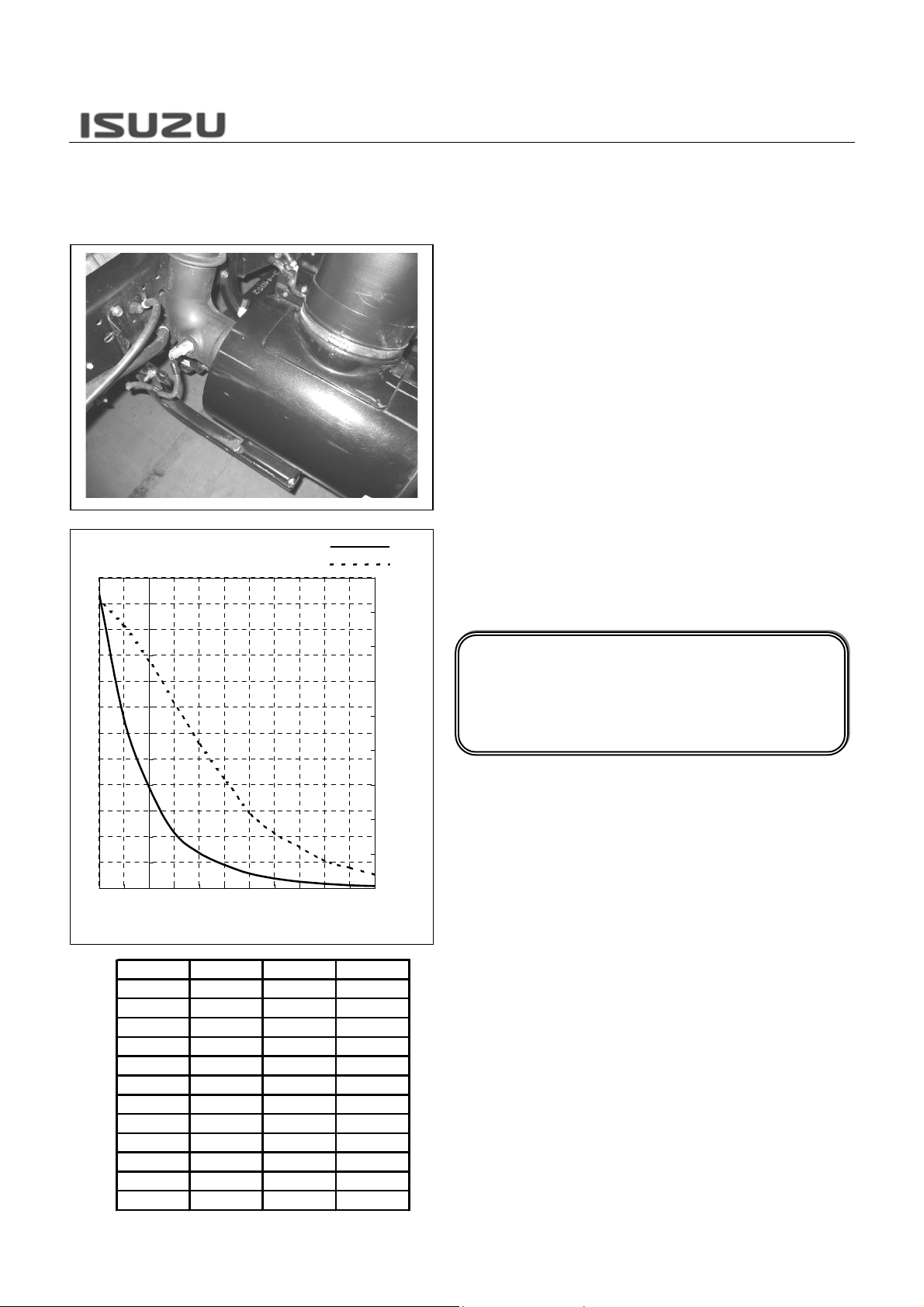
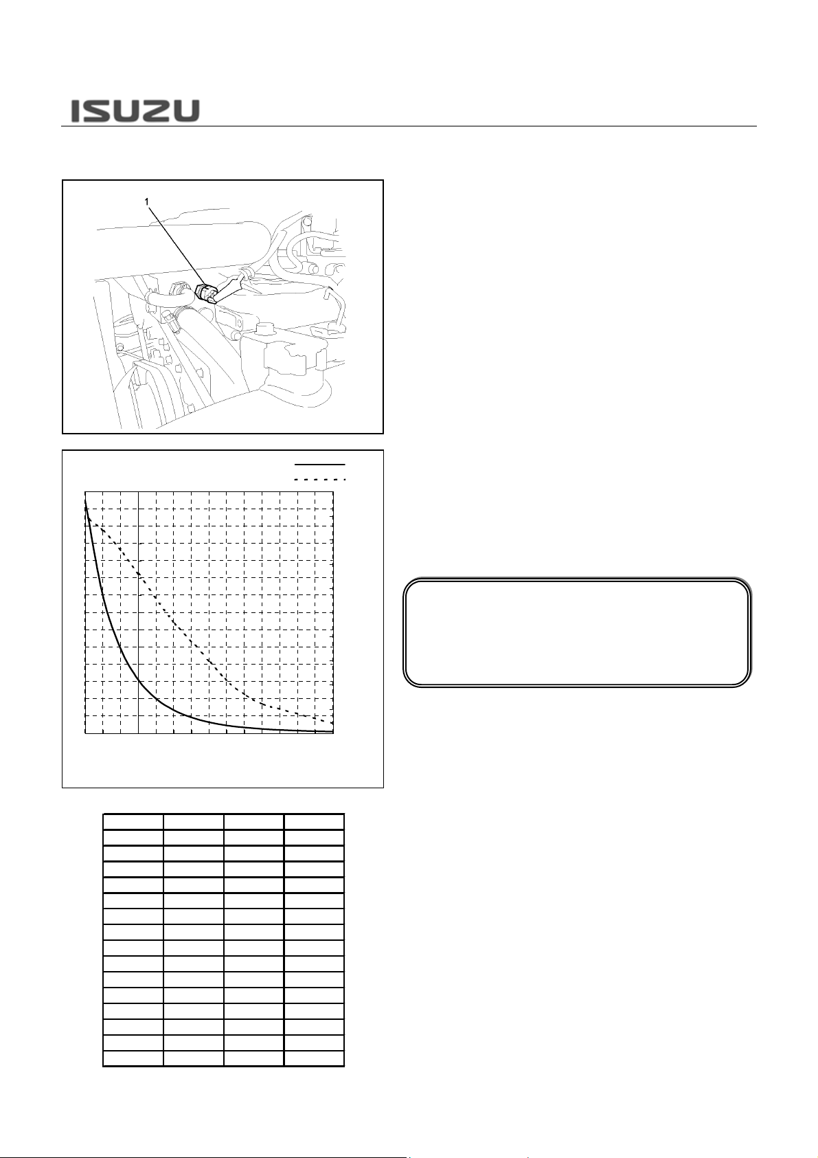
INTAKE AIR TEMPERATURE (IAT)
SENSOR
Resistance (Ohms)
-20-100 102030405060708090
IAT Sensor Characteristic -Reference30000
27500
25000
22500
20000
17500
15000
12500
10000
7500
5000
2500
0
Temperature (C)
°C °F Ohms Volts
90 194 240 0.2
80 176 320 0.3
70 158 450 0.4
60 140 660 0.6
50 122 960 0.8
40 104 1440 1.1
30 86 2300 1.6
20 68 3430 2.1
10 50 5410 2.7
03297703.3
-10 14 16410 3.8
-20 -4 28560 4.2
Ohms
Volts
4.5
4
3.5
3
2.5
2
1.5
1
0.5
0
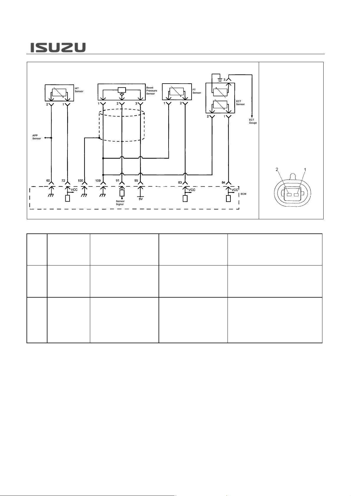
The intake air temperature (IAT) sensor is fitted
between the air cleaner and turbocharger. The IAT
sensor is a variable resistor. The IAT se nsor measures
the temperature of the air entering the engine. The
engine control module (ECM) supplies 5 volts to the I AT
sensor signal circuit and a ground for the IAT senso
low reference circuit. When the IAT sensor is cold, the
sensor resistance is high. When the air temperature
increases, the sensor resistance decreases. With high
sensor resistance, the ECM detects a high voltage on
the IAT sensor signal circuit. With lower senso
resistance, the ECM detects a lower volt age on the IAT
sensor signal circuit. The ECM uses to this value to
calculate a fuel injection quantity, injection timing and
EGR control.
The characteristic of the IAT sen sor is displayed in the
graph and table. Calculated intak e air temperature can
be found on the Tech 2 by unit “°C” or “°F”. The output
voltage also can be found on the Tech 2.
Notice!
In data display “°C” or “°F” will be fixed to a default
value when DTC is set relating to the I AT senso
open or short circuit. To diagnose this DTC,
observe the “Volts” in the data display.
Output (Volts)
N*R 4HK1-TC Engine-22
Related DTC
IAT Sensor
Connector Face
DTC Name On Scan
DTC
P0112 Intake Air Temperature
P0113 Intake Air Temperature
Tool
(IAT) Sensor Circuit
Low Voltage
(IAT) Sensor Circuit
High Voltage
Condition for Running the DTC Condition for Setting the DTC Suspected Cause
DTCs P1630 and P1632 are not
set.
The ignition switch is ON.
The ignition voltage is more than 18
volts.
DTCs P1630 and P1632 are not
set.
The ignition switch is ON.
The ignition voltage is more than 18
volts.
The engine run time is longer than
3 minutes.
The ECM detects that the IAT
sensor signal voltage is less than
0.1 volts for 5 seconds.
The ECM detects that the IAT
sensor signal voltage is more than
4.8 volts for 5 seconds.
Sensor signal circuit is short to ground or short to
the low reference circuit.
Faulty IAT sensor.
Faulty ECM.
Sensor signal circuit is open circuit, high
resistance, short to any 5V or 12V reference
circuit, short to battery or ignition voltage circuit.
Sensor low reference circuit is open circuit or
high resistance.
Poor harness connector connection.
Faulty IAT Sensor.
Faulty ECM.
N*R 4HK1-TC Engine-23
ENGINE COOLTANT TEMPERATURE
(ECT) SENSOR
5
4.5
4
3.5
3
2.5
2
1.5
1
0.5
0
0
Ohms
Volts
Output (Volts)
ECT Sensor Characteristic -Reference28000
26000
24000
22000
20000
18000
16000
14000
12000
10000
Resistance (Ohms)
8000
6000
4000
2000
0
-30-20-100 10203040506070809010011
Temperature (C)
°C °F Ohms Volts
110 230 160 0.2
100 212 200 0.3
90 194 260 0.4
80 176 350 0.5
70 158 470 0.6
60 140 640 0.8
50 122 880 1.1
40 104 1250 1.5
30 86 1800 1.9
20 68 2650 2.3
10 50 4000 2.8
0 32 6180 3.3
-10 14 9810 3.8
-20 -4 16000 4.2
-30 -22 27000 4.5
The engine coolant temperature (ECT) sensor is
installed to the coolant stream on the thermostat
housing. It is a variable resistor. The ECT senso
measures the temperature of the engine coolant. The
engine control module (ECM) supplies 5 volts to the
ECT sensor signal circuit and a ground for the ECT
sensor low reference circuit. When the ECT sensor is
cold, the sensor resistance is high. When the ai
temperature increases, the sensor resistance
decreases. With high sensor resistance, the ECM
detects a high voltage on the ECT sensor signal circuit .
With lower sensor resistance, the ECM detec ts a lowe
voltage on the ECT sensor signal circuit. The ECM uses
to this value to calculate a fuel injection quantity,
injection timing and EGR control and pr ehe ating control.
1.Engine Coolant Temperature (ECT) Sensor
The characteristic of the ECT sensor is di splayed in the
graph and table. Calculated coolant temper ature can be
found on the Tech 2 by unit “°C” or “°F“. The output
voltage also can be found on the Tech 2.
Notice!
In data display “°C” or “°F” will be fixed to a default
value when DTC is set relating to the ECT sensor.
To diagnose this DTC, observe the “Volts” in the
data display.
N*R 4HK1-TC Engine-24
Related DTC
ECT Sensor
Connector Face
DTC Name On Scan
DTC
P0117 Engine Coolant
P0118 Engine Coolant
Tool
Temperature (ECT)
Sensor Circuit Low
Voltage
Temperature (ECT)
Sensor Circuit High
Voltage
P1173 Engine Overheat
Condition for Running the DTC Condition for Setting the DTC Suspected Cause
DTCs P1630 and P1634 are not
set.
The ignition switch is ON.
The ignition voltage is more than
18 volts.
DTCs P1630 and P1634 are not
set.
The ignition switch is ON.
The ignition voltage is more than
18 volts.
The engine run time is longer than
3 minutes.
DTCs P0117, P0118, P1630 and
P1634 are not set.
The ignition switch is ON.
The ignition voltage is more than
18 volts.
The engine is running.
The ECM detects that the ECT
sensor signal voltage is less than
0.1 volts for 5 seconds.
The ECM detects that the ECT
sensor signal voltage is more than
4.8 volts for 5 seconds.
The ECM detects that the ECT is
more than 110°C (230°F) for 5
seconds.
Sensor signal circuit is short to ground or short to
the low reference circuit.
Faulty ECT sensor.
Faulty ECM.
Sensor signal circuit is open circuit, high
resistance, short to any 5V or 12V reference
circuit, short to battery or ignition voltage circuit.
Sensor low reference circuit is open circuit or
high resistance.
Poor harness connector connection.
Faulty ECT Sensor.
Faulty ECM.
Engine overheat.
Faulty engine cooling system
Faulty ECT sensor.
N*R 4HK1-TC Engine-25
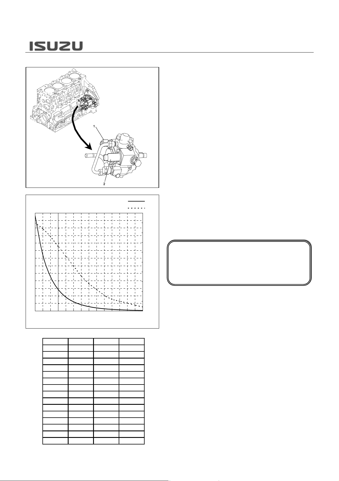
FUEL TEMPERATURE (FT) SENSOR
FT Sensor Characteristic -Reference26000
24000
22000
20000
18000
16000
14000
12000
10000
8000
Resistance (Ohms)
6000
4000
2000
0
-30 -20 -10 0 10 20 30 40 50 60 70 80 90 100 110
°C °F Ohm s V o lts
110 230 140 0.2
100 212 180 0.3
90 194 240 0.4
80 176 310 0.5
70 158 420 0.6
60 140 580 0.9
50 122 810 1.1
40 104 1150 1.5
30 86 1660 1.8
20 68 2450 2.3
10 50 3700 2.8
0 32 5740 3.3
-10 14 9160 3.8
-20 -4 15000 4.2
-30 -22 25400 4.5
Temperature (C)
Ohms
Volts
5
4.5
4
3.5
3
2.5
2
1.5
1
0.5
0
The fuel temperature (FT) sensor is installed to the
supply pump. It is a variable resistor. The FT senso
measures the temperature of the fuel. The engine
control module (ECM) supplies 5volts to the FT senso
signal circuit and a ground for the FT sensor low
reference circuit. When the FT sensor is cold, the
sensor resistance is high. When the air temperature
increases, the sensor resistance decreases. With high
sensor resistance, the ECM detects a high voltage on
the FT sensor signal circuit. With lower senso
resistance, the ECM det ects a lower voltage on the FT
sensor signal circuit. The ECM uses to this value to
calculate a fuel injection volume, injection timing and
EGR control.
1.
Fuel Temperature (FT) Sensor
2. Suction Control Valve (SCV)
The characteristic of the FT sensor is displayed in the
graph and table. Calculated coolant temper ature can be
found on the Tech 2 by unit “°C” or “°F “. The output
voltage also can be found on the Tech 2.
Notice!
In data display “°C” or “°F” will be fixed to a default
value when DTC is set relating to the FT sensor.
To diagnose this DTC, observe the “Volts” in the
Output (Volts)
data display.

N*R 4HK1-TC Engine-26
Related DTC
FT Sensor
Connector Face
DTC Name On Scan
DTC
P0182 Fuel Temperature
P0183 Fuel Temperature
Tool
Sensor Circuit Low
Voltage
Sensor Circuit High
Voltage
Condition for Running the DTC Condition for Setting the DTC Suspected Cause
DTCs P1630 and P1634 are not
set.
The ignition switch is ON.
The ignition voltage is more than
18 volts.
DTCs P1630 and P1634 are not
set.
The ignition switch is ON.
The ignition voltage is more than
18 volts.
The engine run time is longer than
3 minutes.
The ECM detects that the FT
sensor signal voltage is less than
0.1 volts for 5 seconds.
The ECM detects that the FT
sensor signal voltage is more than
4.8 votls for 5 seconds.
Sensor signal circuit is short to ground or short to
the low reference circuit.
Faulty FT sensor.
Faulty ECM.
Sensor signal circuit is open circuit, high
resistance, short to any 5V or 12V reference
circuit, short to battery or ignition voltage circuit.
Sensor low reference circuit is open circuit or
high resistance.
Poor harness connector connection.
Faulty FT Sensor.
Faulty ECM.
N*R 4HK1-TC Engine-27
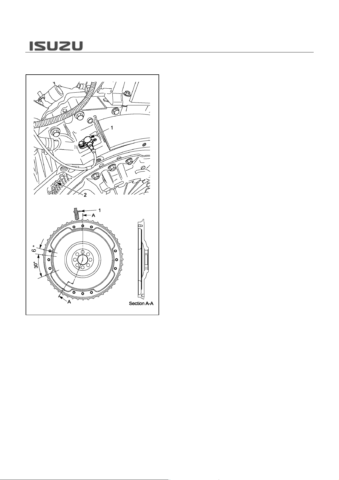
CRANKSHAFT POSITION (CKP) SENSOR
& CAMSHAFT POSITION (CMP) SENSOR
The crankshaft position (CKP) sensor is located on top
of the flywheel housing. There are 56 notches spaced
6deg. apart and a 30deg. section that is uncut. This
uncut portion allows for the detecti on of top dead cente
(TDC). The CKP sensor is a magnet coil type sensor,
which generates an AC signal voltage based on the
crankshaft rotational speed. If th e CKP sensor fails, the
camshaft position (CMP) sensor signals will substitute
for the CKP sensor signal backup.
1. Crankshaft Position (CKP) Sensor
2. Sensor Wheel
N*R 4HK1-TC Engine-28
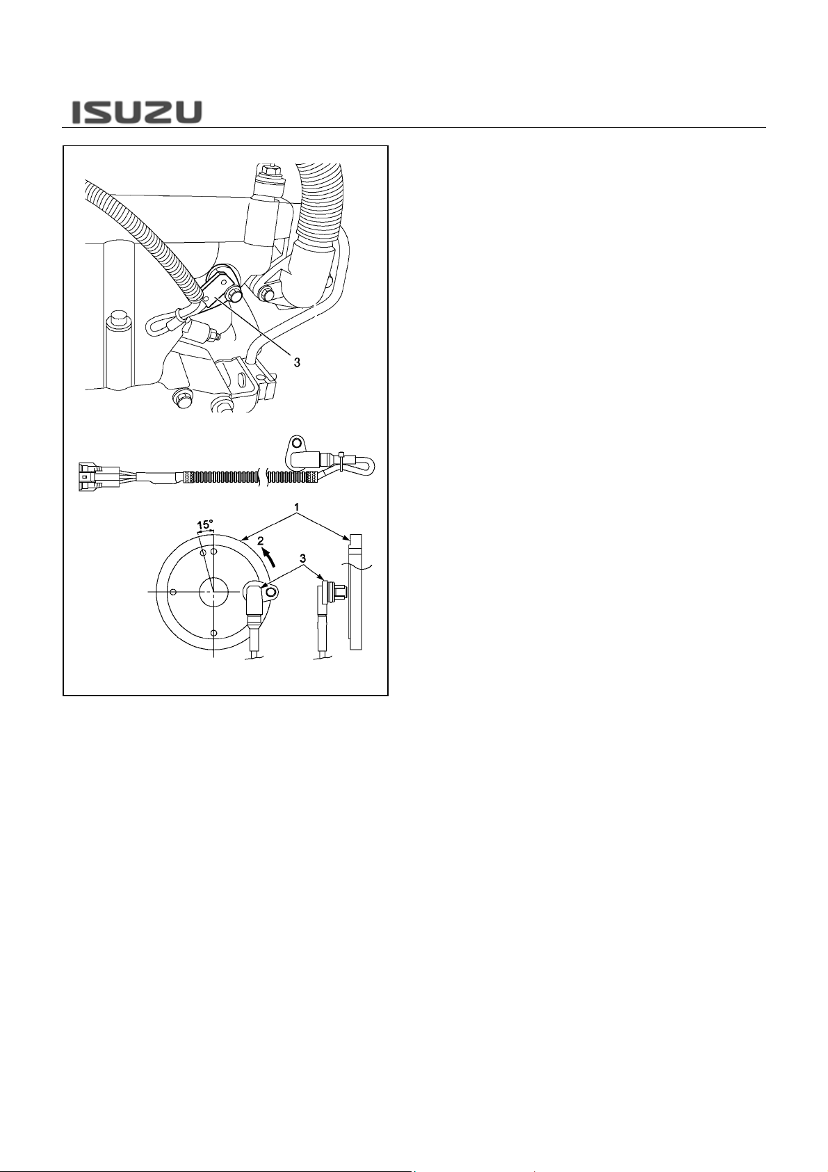
The camshaft position (CMP) s ensor is installed on the
cylinder head at the rear of the camshaft. The CMP
sensor detects a total five through holes, four reference
holes arranged equally every 90deg. space and one
reference hole on the camshaft gea r flan ge surf ac e, and
sends signals to the engine control module (ECM).
Receiving these signals, the ECM determines cylinde
#1 compression top dead center (TDC). If the CMP
sensor fails, the crankshaft position (CKP) senso
signals will NOT substitute for the CMP sensor signal
backup. Engine cranks but does not start.
1. Camshaft Gear
2. Gear Rotating Direction
3. Camshaft Position (CMP) Sensor
6deg.CA
CH1
0V
CH2
0V
No.1 TDC No.3 TDC
30deg.CA
90deg.CA No.1 TDC 30deg.CA
90deg.CA
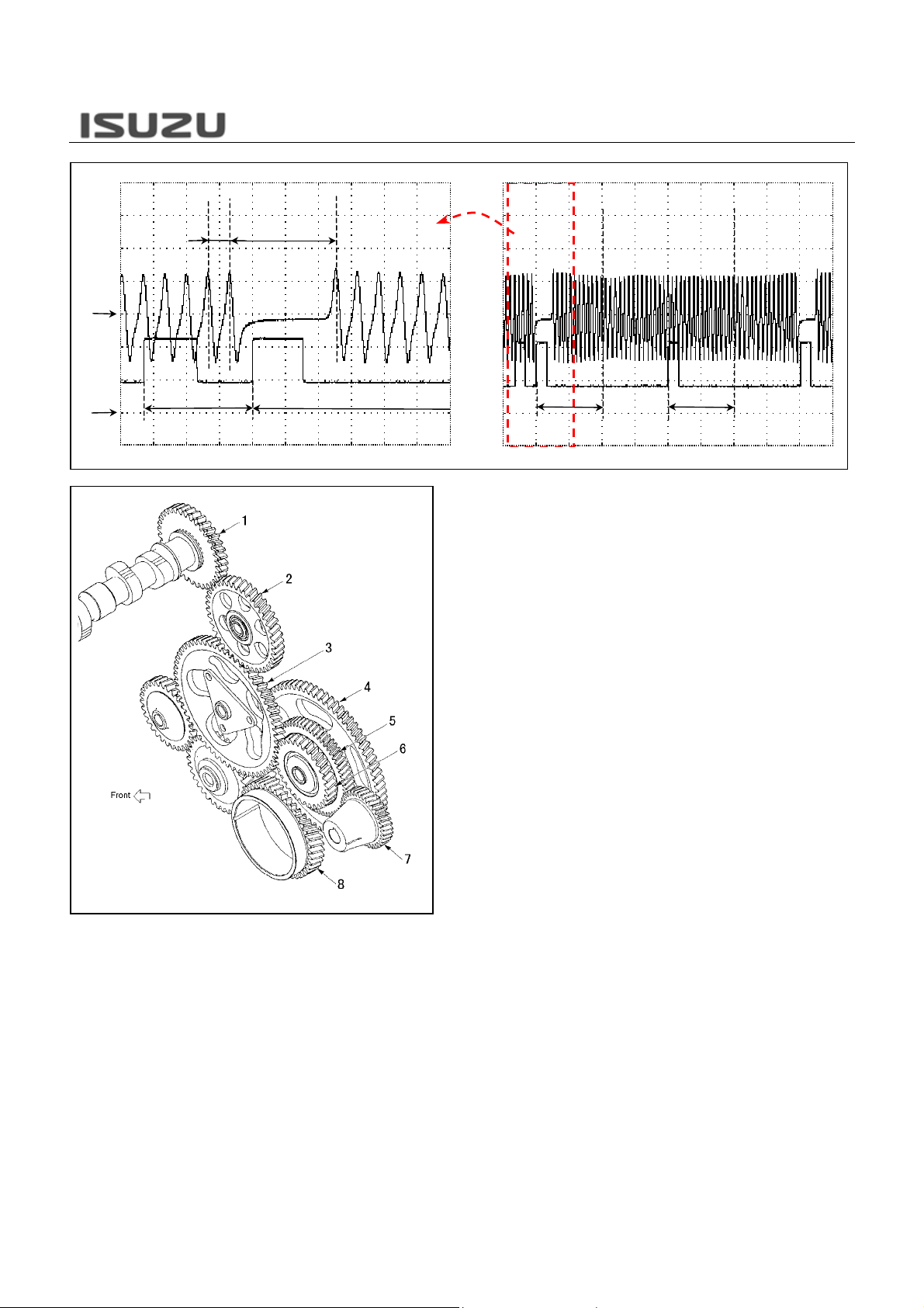
The relationship of CKP sensor and CMP sensor is
displayed on the above picture. The ECM detects 112
CKP sensor pulses (56 x 2) and 5 CMP se nsor pulses
per 2 crankshaft rotations (720 deg.CA). Both senso
wheels are mechanically bit with each other. Theref ore,
the relationship of each pulse is always constant. The
injection timing suitable for the vehicle conditions is
controlled based on the inputs from respecti ve se nso rs.
N*R 4HK1-TC Engine-29
90deg.CA
Loading…
ISUZU-CLUB
ISUZU CLUB — Интернет-магазин автозапчастей
Москваул.Адмирала Лазарева, д.34
8 (968) 913-04-81info@isuzu-club.net
г. Москва, ул.Адмирала Лазарева, д.34ISUZU-CLUB
RUB
Двигатели Isuzu 6HK1, 4HK1. Руководство по ремонту
Автомануал по ремонту Двигатели Isuzu в электронном виде. Руководство будет всегда под рукой во время обслуживания и ремонта автомобиля, для этого его достаточно бесплатно скачать на планшет или телефон в формате pdf.
Перед использованием автомануала проверьте соответствие года выпуска и двигателя автомобиля.
Язык: русский
Формат: pdf
Размер файла: 302,7 Mb
Двигатели Isuzu 6HK1, 4HK1. Руководство по ремонту
Книга по ремонту Двигатели Isuzu
Книга по ремонту Двигатели Isuzu содержит в себе все необходимые сведения, которые помогут владельцу разобраться в устройстве автомобиля, научат грамотному уходу за автомобилем, своевременному техническому обслуживанию и правильному ремонту.
Руководство по ремонту Двигатели Isuzu разделено на главы:
Устройство автомобиля (описываются общие сведения и паспортные данные автомобиля);
Инструкция по эксплуатации (подготовка к выезду, рекомендации по безопасности движения);
Неисправности в пути (советы, которые помогут Вам в случае неожиданной поломки в дороге);
Техническое обслуживание (подробные рекомендации по проведению всех процедур обслуживания);
Инструкции по ремонту (двигатель, трансмиссия, ходовая часть, рулевое управление, тормозная система, а также включены сборочно-разборочные работы, необходимые в процессе ремонта Двигатели Isuzu);
Электрооборудование (подробный мануал по диагностике и устранению неисправностей, отдельно описаны основные блоки и даны подробные электрические схемы Двигатели Isuzu).
Любая из процедур ремонта Двигатели Isuzu приведена по принципу от простого к сложному: от простейших операций по обслуживанию, регулировке, замене деталей, до глобального ремонта со сборочно-разборочными работами.
Все материалы книги основаны на конкретном опыте, полученном в процессе полной разборки и сборки Двигатели Isuzu высококвалифицированными автомеханиками.
Книга «Двигатели Isuzu 6HK1, 4HK1. Руководство по ремонту» необходима, чтобы диагностика и ремонт Двигатели Isuzu могли быть сделаны профессионально и быстро даже владельцем автомобиля, который ещё имеет мало практического опыта.
Бесплатно скачать руководство по ремонту Двигатели Isuzu Вы можете в формате pdf. Его достаточно закачать в свой телефон либо планшет и в любой ситуации на дороге Вы сможете им воспользоваться.
Источник
ISUZU Truck Service Manuals, Fault Codes and Wiring Diagrams
Isuzu 4HK-1 And 6HK-1 Engine Fuel System Ce Applications.pdf
Isuzu 4HK-1 Engine Service Manual.pdf
ISUZU C-series Truck Service Manual.pdf
Isuzu Commercial Truck Forward Tiltmaster Service Manual Supplement 2003.pdf
ISUZU Common Rail System for 4HK1-6HK1 Type Engine Service Manual.pdf
ISUZU cyz-exr Service Manual.pdf
ISUZU E-series Truck Service Manual.pdf
Isuzu Elf 2000 Workshop Manual.rar
Isuzu Elf Service Manual.pdf
ISUZU F-series Truck Service Manual.pdf
ISUZU Forward Service Manual.pdf
Isuzu FRR-series truck Parts Catalog.pdf
ISUZU FSR90 Truck Service Manual.pdf
ISUZU FVR34 Truck Service Manual.pdf
ISUZU LTG PDF manual + DTCs.pdf
Isuzu N-Series Maintenance Manual.rar
ISUZU N-series Truck Service Manual.pdf
Isuzu N-Series Workshop Manual.rar
ISUZU NKR55 Truck Service Manual.pdf
Isuzu NQR 2006 PDF Manual.pdf
ISUZU NQR71 Truck Service Manual.pdf
ISUZU NQR75 Truck Service Manual.pdf
ISUZU Truck Body Builder Guide 2003.pdf
ISUZU Truck Body Builder Guide.pdf
ISUZU Truck Service Manual.pdf
3102 Isuzu Ftr Wiring Diagram.gif
Engine wiring84_PMGR Isuzu Ftr Wiring Diagram.JPG
Isuzu Elf N-series starting schematic wiring diagram.png
Isuzu Pickup 4×4 EFI Fuse Box Wiring Diagram.gif
Map_sensor_wire_diagram%202 Isuzu Ftr Wiring Diagram.JPG
Orig Isuzu Ftr Wiring Diagram.jpg
Qu83668_800 Isuzu Ftr Wiring Diagram.jpg
History of the brand ISUZU
40th years of the twentieth century became no less successful than the previous decade. Already in 1941, Tokyo Automobile Industries received permission from the Japanese government to manufacture cars equipped with diesel power units, becoming the only such company throughout the country. In 1945, the postwar production of the TX40 truck was resumed, and the active sales of the TU60 also began. And in 1949 the company was renamed to Isuzu Motors Limited. The only negative factor was the separation of Hino Works, one of the parts of the corporation, and the subsequent establishment of an independent company Hino Heavy Industries in 1942.
The beginning of the next decade was marked by the successful development of the diesel V-shaped 8-cylinder engine with water cooling, which received the index DA80. In early 1953, Isuzu Corporation presented the first ever company, made in cooperation with the British firm Rootes, a Hillman car, which became a copy of the British car of the same name. By October of the same year, Hillman entered the conveyor production. And in October 1959 was marked by the beginning of the conveyor assembly of the truck Elf LT, equipped with an extremely economical diesel engine DA640.
In the early 60’s, a real production boom occurred, as a result of which representatives of the Isuzu company were presented to the public by a diesel engine for a DL201 car, the volume of which was 2 liters. Approximately at the same time, a new plant was opened in the city of Fujisawa, and new models of cars, the WASP truck and the Bellel and Bellet cars, were also on sale. In the second half of the decade, the new products were a large truck TM, as well as passenger cars 117 Coupe and Florian.
The next decade also began with major presentations: in 1970, the Isuzu Forward cargo models were presented, as well as the Isuzu Elf 350 (KS). One of the most important events in the history of Isuzu was the signing of an agreement on cooperation with the American automobile magnate General Motors, which in 1971 became the owner of 35% of the shares of the Japanese company. The results of joint labor did not take long. Already in 1974, the assembly line for a Gemini passenger car developed within the framework of cooperation between Isuzu and General Motors began. Over the next few years, the company’s lineup was also updated.
So in 1977, the production of Isuzu Florian started with a diesel engine, and in 1979 debuted the diesel version of Gemini. A few years earlier, in 1975, the Isuzu North American division, Isuzu Motors America, was opened, whose prospects, in view of cooperation with General Motors, looked extremely serious. And in the very end of the 70s, the construction of a testing range for the Japanese automaker in Hokkaido was completed. Later, in May 1984, in the same Hokkaido, a new plant was opened. The beginning of the 80s of the 20th century foreshadowed new successes. The main confirmation of this is the rapid upgrade of the lineup.
First, in 1980, a series of commercial Fargo minibuses entered the conveyor assembly, which were almost immediately widely used in Japan. Almost immediately, in the first half of 1981, the passenger car Piazza and SUV Rodeo Bighorn debuted, in 1983 Florian Aska model was put on the conveyor, after half a year celebrating the victory in the British RAC rally. And already in 1985 they introduced the FF Gemini car. In the same year 1985, the first representative office of Isuzu in China was opened, which was originally considered as the most important market.
At the same time, the 90s were remembered by the fans of Isuzu’s developments and major successes at various competitions. So in 1994, the car Trooper won in two races Paris-Dakar rally, and two years later, the first place in the Australian safari took the model Holden Jackaroo. In addition, the organization received many awards for its innovative developments. And in 1999, the fate again brought Isuzu Motors with the company Hino, as a result of which was established joint production of buses. The beginning of the XXI century marked the receipt by the company representatives of new awards for successful development.
In particular, 2001 was marked by the presentation of the diesel engine Duramax 6600, which was called one of the best powertrains in the history of the automotive industry. At the same time, the Japanese actively worked in foreign markets. At the same time, not only the USA and Asian countries, such as Indonesia, Thailand or Japan, received dividends from this work. The company Isuzu Motors gradually entered the European market. In 2002, a 3-year business plan of the Japanese automaker was adopted, which was supposed to minimize costs and make the company’s revenue more solid. According to this plan, by January 2003 the share of ownership of Isuzu shares by the automobile giant General Motors had decreased to 12%.
At the same time, these companies continued active cooperation. It should be noted the establishment of another joint venture, whose goal was the development of transmissions. According to the new business plan of the company, calculated from April 2005 to March 2008, Isuzu was to become the world leader in the production of diesel engines, as well as commercial vehicles and buses. It should be noted that the company did it. An important role in the development of Isuzu Motors as a world giant was played by the company’s unique developments. In particular, debuted in mid-2005 truck Elf Hybrid with a mixed engine.
After the introduction of new environmental standards in Japan in the same year of 2005, the very important step was the development of the Isuzu Giga truck, which became the first Japanese car in its class to meet these standards. After the dissolution of the alliance between Isuzu Motors and General Motors in 2006, these companies have set up a joint venture, which is already preparing for the presentation its new products, which, according to the plan, will pleasantly surprise the whole world.
Источник
Двигатель 4нк1 исузу ремонт инструкция
Автомануал по ремонту Двигатели Isuzu в электронном виде. Руководство будет всегда под рукой во время обслуживания и ремонта автомобиля, для этого его достаточно бесплатно скачать на планшет или телефон в формате pdf.
Перед использованием автомануала проверьте соответствие года выпуска и двигателя автомобиля.
Язык: русский
Формат: pdf
Размер: 302,7 Mb
Двигатели Isuzu 6HK1, 4HK1. Руководство по ремонту
Книга по ремонту Двигатели Isuzu
Эксплуатация любого автомобиля Двигатели Isuzu невозможна без знаний его устройства, особенностей обслуживания и ремонта. Не имеет значения, кем будут производиться необходимые работы, — каждый водитель просто обязан знать элементарные процедуры ухода и устранения неполадок.
Книга по ремонту Двигатели Isuzu содержит в себе все необходимые сведения, которые помогут владельцу разобраться в устройстве автомобиля, научат грамотному уходу за автомобилем, своевременному техническому обслуживанию и правильному ремонту.
Руководство по ремонту Двигатели Isuzu разделено на главы:
Устройство автомобиля (описываются общие сведения и паспортные данные автомобиля);
Инструкция по эксплуатации (подготовка к выезду, рекомендации по безопасности движения);
Неисправности в пути (советы, которые помогут Вам в случае неожиданной поломки в дороге);
Техническое обслуживание (подробные рекомендации по проведению всех процедур обслуживания);
Инструкции по ремонту (двигатель, трансмиссия, ходовая часть, рулевое управление, тормозная система, а также включены сборочно-разборочные работы, необходимые в процессе ремонта Двигатели Isuzu);
Электрооборудование (подробный мануал по диагностике и устранению неисправностей, отдельно описаны основные блоки и даны подробные электрические схемы Двигатели Isuzu).
Любая из процедур ремонта Двигатели Isuzu приведена по принципу от простого к сложному: от простейших операций по обслуживанию, регулировке, замене деталей, до глобального ремонта со сборочно-разборочными работами.
Все материалы книги основаны на конкретном опыте, полученном в процессе полной разборки и сборки Двигатели Isuzu высококвалифицированными автомеханиками.
Книга «Двигатели Isuzu 6HK1, 4HK1. Руководство по ремонту» необходима, чтобы диагностика и ремонт Двигатели Isuzu могли быть сделаны профессионально и быстро даже владельцем автомобиля, который ещё имеет мало практического опыта.
Бесплатно скачать руководство по ремонту Двигатели Isuzu Вы можете в формате pdf. Его достаточно закачать в свой телефон либо планшет и в любой ситуации на дороге Вы сможете им воспользоваться.
Двигатели Isuzu 6HK1, 4HK1. Руководство по ремонту
книга по ремонту Двигатели Isuzu в формате pdf (302,7 Mb)
4НК1 (Евро-3) с системой впрыска топлива
rykovodstvo.ru > Руководство эксплуатация > Документы
4НК1 (Евро-3) с системой впрыска топлива
Требования стандартов Евро-3 к токсичности выхлопа введены в Европе с 1999 года, а с 2005 года введены требования Евро-4. По указанным требованиям Евро-3 ограничивается содержание в выхлопных газах дизельных двигателей окислов азота NOX до – 0,5…0,7 гр/км и содержание твердых частиц (сажи) до – 0,05…0,08 гр/км.
Пути снижения содержания вредных веществ двигателей различны. Применение фильтров и дожигателей, каталитических нейтрализаторов и мочевины. Но причина кроется в самом процессе сгорания топлива. Для его оптимизации и разработана система подачи топлива Common Rail (т.е. общяя магистраль). Указанная система решила ряд проблем просто и эффективно. При улучшении топливной экономичности на 10…15% возростание мощности составило 40% и это при резком снижении токсичности отработавших газов.
Такая система реализована на двигателе 4НК1. Даный двигатель серийно устанавливается как на массовую модель А-09214, так и на новую модель А-401. Рабочий обьем этого двигателя 5,2 литра мощьность 190 л.с при 2600 об/мин,
крутящий момент 387 Нм при 1500 об/мин.
2. Особенности устройства двигателя 4НК1.
Двигатель 4НК1 дизельный 4-х тактный с непосредственным впрыском топлива, тербонаддувом и промежуточным охладителем нагнетаемого воздуха. Для снижения токсичности выхлопа применена рецигкуляция отработавших газов, управляемая ЭБУД.
ГРМ имеет верхнее расположение распределительного вала и четыре клапана на один цилиндр. Каждая пара клапанов открывается одним коромыслом через специальный общий рычаг.
Управление системой впрыска топлива и системой рециркуляции отработавших газов осуществляет ЭБУД (электронный блок управления двигателем). Сиситема подачи топлива Common Rail.
На данной схеме показаны:
2. Фильтр отстойник.
3. Фильтр тонкой очистки топлива.
4. Топливный насос высокого давления.
8. Датчики положения коленчатого и распределительного валов.
4. Исполнение системы впрыска Common Rail
на автомобиле ISUZU моделиNQR-71P.
В автобусах А-09214(09204) Евро-3 система питания двигателя состоит из следующих агрегатов:
1. Топливный бак – расположен по левой стороне автобуса в средней части.
2. Фильтр-отстойник с ручным топливоподкачивающим насосом – расположен в люкче по левой стороне автобуса.
3. ТНВД (DENSO) с механическим приводом – расположен по левой стороне двигателя в задней части.
4. Топливная рампа – пркручена по левой стороне двигателя.
5. 4 электрофорсунки.
6. Обратные топлипрводы
5. Назначение и принцип действия агрегатов и узлов
системы впрыска Common Rail на автомобиле ISUZU.
Топливный бак
Бак обьемом 150 литров круглого сечения. Имеет магистрали подачи и слива топлива. Снабжен герметичной пробкой и дыхательным клапаном. В бак установлен датчик указателя уровня топлива и дополнительно вварены магистрали подачи и слива топлива для автономного отопителя.
Фильтр-отстойник с ручным
Фильтр отстойник имеет две особенности. 1 – в верхнай части фильтра установлен топливоподкачивающий ручной насос диафрагменного типа. 2 – это датчик уровня воды в стакане отстойника, связанный с системой управленя двигателем.
2-х плунжерный насос совмещенный с механическим топливоподкачивающим. Обеспечиват высокое давление в подающей рампе. Прокачку топлива по системе обеспечивает насос шестеренчатого типа с парой шестерней (одна внутреннего одна наружного зацепления). Привод насоса осуществляется общим валом для подкачивающего и основного насосов. В магистрали низкого давления после подкачивающего насоса есть сетчатый топливный фильтр и клапан ограничения давления. Плунжерные пары приводятся попеременно эксцентриком вала. Смазка насоса осуществляется дизельным топливом. Поэтому НЕДОПУСТИМО доливать в топливо бензин. Крайне важно использование, в зимнее время, зимнего топлива или противогелевых присадок. Кроме того в ТНВД установлены два элемента электронной системы управления двигателем: 1 – датчик температуры топлива, 2 – регулятор высокого давления топлива.
Представляет собой литую деталь с множеством отверстий. В рампе поддерживается давление, равное давлению впрыска, необходимое на конкретном этапе работы двигателя. Кроме того, в рампу установлены нагнетательные клапаны к форсункам, ограничитель давления (от него идет слив в бак), датчик давления топлива.
Форсунки.
Представляют собой устройство врыска топлива под высоким давлением, управляемое ЭБУД. Открытие-закрытие иглы распылителя зависит от подачи напряжения на соленоид форсунки. Запирается игла при помощи давления и возвратной пружины. Особенность конструкции – обратная магистраль расположена под клапанной крышкой.
Электронный блок управления двигателем расположен на левом лонжероне рамы. Имеет два разьема для жгутов управления-подачи данных.
Электрическая схема управления двигателем.
Для выполнения задач по дозированию топлива ЭБУД получает сигналы со следующих датчиков:
— положения коленчатого вала
— положения распределительного вала
— положения педали «газа»
— температуры топлива
— температуры охлаждающей жидкости
— температуры всасываемого воздуха
— давления наддува
— давления топлива
При этом управляющие сигналы от ЭБУД поступают к следующим компонентам:
— регулятор давления на ТНВД
— клапан рециркуляции отработавших газов
6. Расположение датчиков
ЭБУД – расположен на левом лонжероне рамы возле силового агрегата.
Датчик положения коленчатого вала – слева сверху на картере маховика.
Датчик положения распределительного вала – сзади на головке блока цилиндров в районе приводной шестерни.
Датчик положения педали «газа» — возле педали.
Датчик температуры топлива – в ТНВД.
Датчик температуры охлаждающей жидкости – слева на приливе головки блока цилиндров ниже крышки термостатов.
Датчик температуры всасываемого воздуха – в магистрали подачи воздуха после воздушного фильтра.
Датчик давления наддува – в трубопроводе от промежуточного охладителя (интеркуллера) до впускного коллектора.
Датчик давления топлива – в топливной рампе.
7.Диагностика системы подачи топлива
При включении на панели приборов контрольной лампы Check Engine (желотого цвета) необходимо выявить в какой части электронной или электрической системы возникла неисправность. Для этой цели можно воспользоваться считыванием кодов ошибок. Получив коды и выяснив их значение можно устранить неисправность.
Для перевода ЭБУД в режим самодиагностики нужно выполнить седующие действия:
1. Соединить на диагоностическом разьеме 1-е и 4-е гнездо при помоши провода.
2. Включить зажигание.
3. Сосчитать мигание контрольной лампы Check Engine. Порядок подачи сигналов имеет определенную последовательность. В начале лампа выдает троекратно код 12 (одно включение, перерыв, два включения). Это свидетельствует о том, что система переведена в режим самодиагностики. Затем седует троекратное повторение каждого кода ошибок. В конце снова идет код 12, что свидетельствует о завершении самодиагностики.
4. Выключить зажигание.
Воспользовавшись таблицей кодов ошибок найти необходимый код и определить вид неисправности. В графе метод устранения прочитать путь решения проблемы. Для этого может понадобиться выполнить определенную последовательность операций.
После устранения неисправности необходимо стереть коды ошибок из памяти ЭБУД. Для этого, согласно японской инструкции, необходимо выполнить следующие действия:
1. Перевести систему в режим самодиагностики соединением соответствующих гнезд.
2. Включить зажигание.
3. Плавно нажать-отпустить педаль «газа» (время операции 4 секунды).
4. Повторять нажатие-отпускание 4 раза.
5. Выключить зажигание.
6. После перерыва не менее 30 секунд повторить п.п. 2-5 по количеству кодов ошибок.
7. Отключить самодиагностику.
Если коды удалены из памяти ЭБУД, то контрольная лампа Check Engine не включается на панели приборов.
8. Диагностика при помощи сакнера
Для более эффективной работы по устранению неисправностей применяют сканер кодов Tech-2. Порядок работы со сканером довольно прост. Прибор сразу выдает описание неисправности, поэтому нет необходимотси в считывании кодов и пользовании таблицами. Кроме того, при помощи Tech-2 быстро стираются и коды неисправностей из памяти болка.
1. Подключить прибор к сети питания. Важно соблюсти указания по напряжению питания воизбежание выхода прибора из строя.
2. Соединить стандартный разьем SAE 16/19 прибора с диагностическим разьемом автобуса (грузовика).
3. Включить прибор (должен засветиться экран).
4. Нажать синюю кнопку ENTER.
5. Из открытого меню выбрать F0: Диагностика.
6. Из меню «Год выпуска» выбираем 2005 год (это не год выпуска авто, а год выпуска данной модели системы управления).
7. Из меню «Модель» выбрать (N*) ELF,NPR,NQR,VFR.
8. Из седующего меню выбрать F0: Двигатель.
9. Из следующего меню выбрать 4НК1-ТС.
10. Появится предписание «Включите зажигание». Включаем зажигание и нажимаем кнопку без маркировки под надписью на экране «Подтвердить».
11. Из следующего меню выбираем «Считывание кодов неисправностей».
12. После устранения кодов неисправностей повторяем п.п. 1-10. После чего в меню выбираем «Стирание кодов ошибок» и подтвеждаем кнопкой под экраном прибора.
9. Дополнительная инфотрмация.
Для установки ТНВД, демонтированного с двигателя, необходимо выполнить следующие действия:
1. Совместить метку на шкиве привода навесных агрегатов с меткой ВМТ на приливе передней крышки блока цилиндров.
2. Совместить метку на приводной шестерне ТНВД с меткой на корпусе ТНВД.
3. Установить насос в блок двигателя.
Источник
INTRODUCTION & ENGINE MECHANICAL FEATURES
The 2005 model year NPR/NQR truck, the 4HK1-TC inline 4 cylinder engine replaces the 4HE1-TC engine for advanced exhaust emission countries. The 4HK1-TC engine has been newly developed on the basis of previous 4HE1-TC engine, with additional features including the employment of four valve mechanism per a cylinder that are operated via a single camshaft, common rail fuel injection system, water-cooled exhaust gas re-circulation (EGR) system, and the change of combustion chamber form. The larger engine displacement and the common rail fuel injection system have resulted in an increase both in maximum output and torque, and met Euro 3 emission regulation standard. Most conspicuous items are listed below.
- Multi fuel injection type high-pressure common rail system and is made with Denso.
- Single overhead camshaft (OHC) with 4 valves per a cylinder.
- Electrical control EGR valve, water-cooled EGRcooler.
- Turbocharger with intercooler.
The base transmission is MYY for 4HK1-TCN low output engine, MZZ for 4HK1-TCS high output engine. The Smoother system is available for only MYY transmission.
GEAR TRAIN
To rotate the fuel supply pump with engine speed, idle gear has changed with three steps. The crankshaft gear (42 teeth) corresponds with the large diameter of idle gear A (72 teeth). The fuel supply pump gear (35 teeth) corresponds with the middle diameter of idle gear A (60 teeth). The idle gear B (61 teeth) corresponds with the small diameter of idle gear A (30 teeth).
Valve Train
To improve exhaust emission and engine output performance, four valve mechanism is newly adopted for 4HK1-TC engine. Note that the adjustment method of valve clearance has been changed from 4HK1-TC engine as following steps:
- Rotate the crankshaft to make the No.1 cylinder meet the compression top dead center (TDC). There are 2 marks stamped on the crank pulley. The mark (1) is used to bring the engine No.1 or No. 4 cylinder to TDC. The mark (2) is irrelevant. Do not use the mark (2).
- Loosen fully each adjusting screw (8) & (2) of the bridge and the rocker arm.
- Insert a 0.4mm (0.016in) thickness gauge between the tip of the rocker arm and bridge cap (5), and adjust the clearance with the adjusting screw (3) on the rocker arm, and then fix it with a lock nut (4).
- With a thickness gauge kept inserted, check that the adjusting screw (6) contacts the valve shaft end and the movement of the thickness gauge has become tight when the adjusting screw (6) on the bridge is tightened lightly.
- Check the valve shaft end on the opposite side floats or it contacts obliquely. In case of a floating or oblique contact, loosen a little the adjusting screw (6) on the bridge side and adjust so that the valve shaft ends on both sides get in contact properly. Bridge (8) & valve shaft end clearance less than 0.1 mm (0.004in).
- After the adjustment so that the end of the valves on both sides touch properly, tighten up the lock nut (7) on the bridge (8).
CYLINDER HEAD COVER & HEAD COVER CASE
Along with the employment of a common rail type fuel injection system, the head cover is split and housed in a newly introduced head cover case attached with an intermediate connector for the injector. The head cover case is so designed that it is secured individually to the cylinder head with four bolts, and further it is tightened together with the head cover with nine bolts. Accordingly, the head cover is removable individually regardless of the injector harness, thus enabling easy inspection and service including the valve clearance adjustment.
ENGINE CONTROL MODULE (ECM)
The engine control module (ECM) is located at inside of engine-side cover on the left via mounting bracket and is beside the engine. The ECM is made by Transtron. The ECM mainly controls the following:
- Fuel injection control
- Fuel timing control
- Exhaust gas recirculation (EGR) system control
- Preheating system control
- Exhaust brake control
- Power take off (PTO) control
- On-board diagnostics for engine control
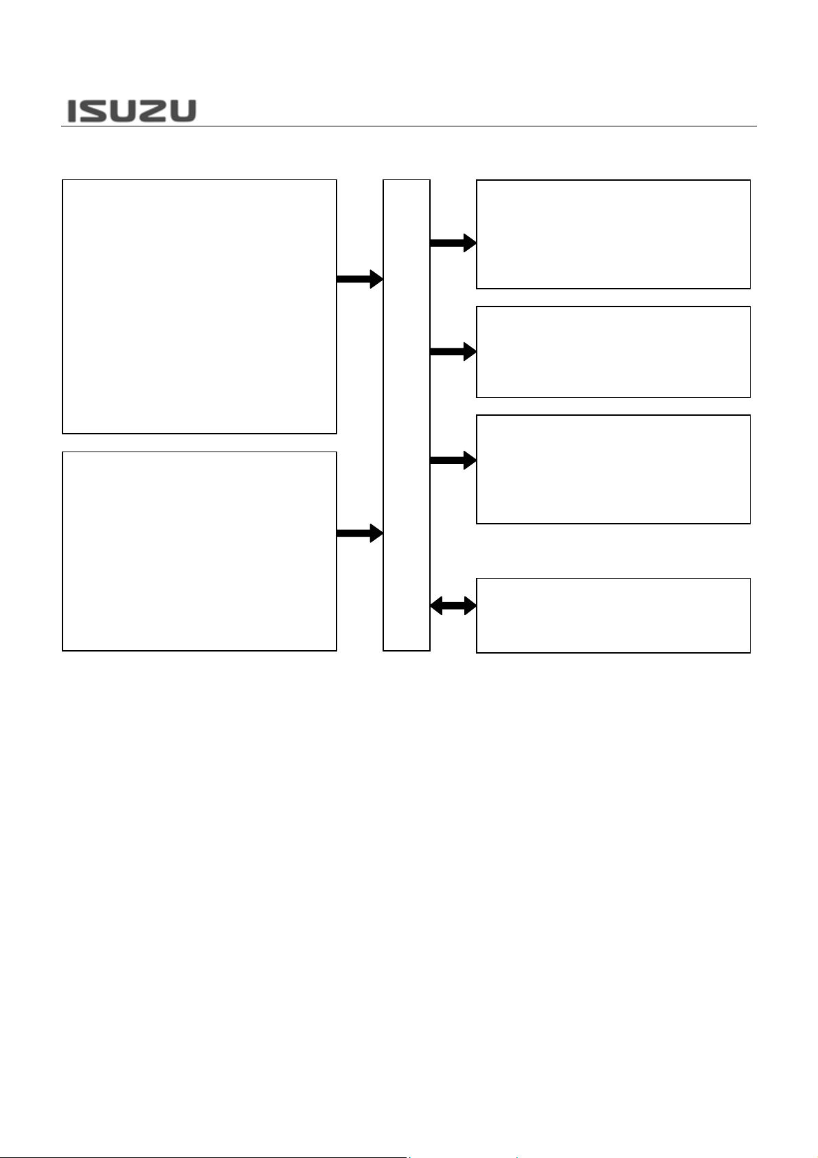
The ECM constantly observes the information from various sensors. The ECM controls the systems that affect vehicle performance. The ECM performs the diagnostic function of the system. The ECM can recognize operational problems, alert the driver through the malfunction indicator lamp (MIL), and store diagnostic trouble code (DTC). DTC identify the system faults to aid the technician in making repair.
This diagnostic applies to internal microprocessor integrity conditions within the ECM. The electronically erasable programmable read only memory (EEPROM) memorize learning data and injector ID code data for engine control and communication with other control module.
Symbol “!” warns you of an electric shock hazard. To avoid shock and possible serious injury, DO NOT touch the terminals. When disconnecting the harness connector, always turn OFF the ignition switch or disconnect the battery cable.