
Valve FX
Guitar Preamp/
Signal Processor
A Harman International Company
INPUT OUTPUT PRESENCE
GUITAR PREAMP / SIGNAL PROCESSOR
DSP Clip
-18
-12
-6
0
Bypass
Program Number
FX
S-DISC
™
PROCESSING

1
Table Of Contents…………………………………………………….1
Introduction ……………………………………………………………..3
Safety Precautions ……………………………………………………3
Lithium Battery Warning…………………………………………….4
Warranty………………………………………………………………….4
SECTION 1 — STARTUP Supplying Power………………………………………………………6
Front Panel Controls …………………………………………………6
Input………………………………………………………………….6
Headphone Output……………………………………………..6
Main Output Level ………………………………………………6
Presence Control………………………………………………..6
Display Window………………………………………………….7
Cursor Keys……………………………………………………….7
Effects Access……………………………………………………8
Global Buttons……………………………………………………8
Data Wheel ………………………………………………………..8
Power Switch ……………………………………………………..8
Rear Panel Connections ……………………………………………8
AC Line Input……………………………………………………..8
Foot Controller ……………………………………………………8
MIDI In ………………………………………………………………8
MIDI Out ……………………………………………………………8
Outputs……………………………………………………………..9
Input………………………………………………………………….9
MIDI and Audio Setups……………………………………………..9
SECTION 2 — BASIC OPERATIONS Main Operating Mode……………………………………………….11
Parameter Architecture……………………………………………..11
Accessing Factory Programs …………………………………….12
SECTION 3 — PROGRAMMING Using the Function Keys……………………………………………13
More Special Characters …………………………………………..13
The Effects Access Keys…………………………………………..14
About The I/O Module……………………………………………….14
Modifying Factory Programs………………………………………14
Basic Program Creation…………………………………………….16
Selecting an Algorithm………………………………………………16
Storing and Naming Programs …………………………………..17
SECTION 4 — EFFECTS AND PARAMETERS About The Effects Library ………………………………………….20
Analog Effects………………………………………………………….20
Compressor……………………………………………………….20
Distortion……………………………………………………………20
Equalizers ……………………………………………………………….22
4-band PEQ / 10-band GEQ ………………………………..22
Cabinet Emulator………………………………………………..23
Reverbs…………………………………………………………………..24
BigVerb / MFX Reverb…………………………………………24
Gated Reverb …………………………………………………….28
Delays / Sampler………………………………………………………30
Delays……………………………………………………………….30
Sampler …………………………………………………………….32
Pitch Shifters ……………………………………………………………34
Pitch Shifters………………………………………………………34
Detuners ……………………………………………………………35
Whammy™ ………………………………………………………..35
Arpeggiators………………………………………………………36
Table of Contents
Valve FX Owner’s Manual

2
Modulation Effects ……………………………………………………37
Choruses …………………………………………………………..37
Flangers…………………………………………………………….38
Phasers……………………………………………………………..39
Tremolos……………………………………………………………39
Auto Panners ……………………………………………………..39
Mixers……………………………………………………………………..40
More ……………………………………………………………………….41
Noise Gates……………………………………………………….41
DSP Level ………………………………………………………….42
Wahs…………………………………………………………………42
Duckers …………………………………………………………….42
Phase Inverter ……………………………………………………43
SECTION 5 — THE UTILITY MENU Utility Menu ……………………………………………………………..44
MIDI Sub-Menu………………………………………………………..44
MIDI Channel …………………………………………………………..44
Send Prg (Program Change)……………………………………..45
Prg Send Map………………………………………………………….45
Prg Rcv Map ……………………………………………………………47
Continuous Controller Links……………………………………….48
Display CC’s ……………………………………………………………52
Bulk Dump ………………………………………………………………52
MIDI Program Dump…………………………………………………53
MIDI Merging …………………………………………………………..54
Programming The Footswitch …………………………………….54
Patch Assignment…………………………………………………….55
Program, Bank Up/Down …………………………………………..56
Toggle CC……………………………………………………………….56
Int Ped = CC……………………………………………………………56
List Up / Down …………………………………………………………57
Prg List Asssign ……………………………………………………….57
Continuous Control Pedal ………………………………………….58
Assign CC Number…………………………………………………..58
CC Transmit Channel………………………………………………..59
Pedal Calibration………………………………………………………60
LED Assignment ………………………………………………………62
Tuning From The Front Panel …………………………………….62
Tuning From The Foot Controller ………………………………..63
Changing The Tuning Reference ……………………………….63
Adjusting The LCD Contrast………………………………………64
Output Mode……………………………………………………………64
Cabinet Emulation…………………………………………………….65
Sales Banner……………………………………………………………65
Reinitializing The Valve FX…………………………………………66
SECTION 6 — APPENDIX Specifications…………………………………………………………..68
Factory Algorithm Diagrams ………………………………………69
Block Diagram …………………………………………………………78
Factory Program List…………………………………………………79
MIDI Implementation Chart………………………………………..80
Table of Contents
Valve FX Owner’s Manual

3
INTRODUCTION Congratulations, and thank you for your purchase of the DigiTech
Valve FX Guitar Preamp / Signal Processor. The Valve FX combines
the world’s most powerful digital signal processor, the S-DISC™ with
real tube distortion or one of our three most popular solid state distortion types. These digital multi-effects are second to none, and when
joined with the warmth and clarity of one of the best analog preamps
on the market, the results are amazing. Special features of the Valve
FX include:
• Full bandwidth effects (20-20kHz)
• 24-bit signal path, 48-bit internal data transmission
• Stereo processing
• Instant Module and Parameter access
• The Control One remote foot controller (optional)
• Programmable cabinet emulation for running direct to a mixing
console (great for both studio and live applications)
• Front panel Presence control and headphone output
• Full MIDI implementation
• Built-in MIDI merging (MIDI output can act as a standard out or
as a merged out)
• MIDI Transmit and Receive mapping
• All effects and parameters are available for MIDI continuous
control with up to 10 CC links available per program
For the first time, all of your effects needs can be filled by a single unit
with 16-bit digital clarity. This owner’s manual is your key to understanding the powerful world of the Valve FX. Read it carefully. After
you’ve had time to familiarize yourself with the unit, try experimenting
with unusual effects settings. You may achieve some interesting
results.
SAFETY PRECAUTIONS
The symbols shown above are internationally accepted symbols that
warn of potential hazards with electrical products. The lightning flash
with arrowpoint in an equilateral triangle means that there are dangerous voltages present within the unit. The exclamation point in an equilateral triangle indicates that it is necessary for the user to refer to the
owner’s manual.
Introduction and Safety Precautions
Valve FX Owner’s Manual
CAUTION
RISK OF ELECTRIC SHOCK
DO NOT OPEN
ATTENTION:
WARNING:
SHOCK DO NOT EXPOSE THIS EQUIPMENT TO RAIN OR MOISTURE
RISQUE DE CHOC ELECTRIQUE — NE PAS OUVRIR
TO REDUCE THE RISK OF FIRE OR ELECTRIC

4
These symbols warn that there are no user serviceable parts inside
the unit. Do not open the unit. Do not attempt to service the unit
yourself. Refer all servicing to qualified personnel. Opening the
chassis for any reason will void the manufacturer’s warranty. Do not
get the unit wet. If liquid is spilled on the unit, shut it off immediately
and take it to a dealer for service. Disconnect the equipment during
storms to prevent damage.
U.K. ONLY — A moulded mains plug that has been cut off from the
cord is unsafe. Discard the mains plug at a suitable disposal facility.
NEVER UNDER ANY CIRCUMSTANCES SHOULD YOU INSERT A
DAMAGED OR CUT MAINS PLUG INTO A 13 AMP POWER SOCKET.
Do not use the mains plug without the fuse cover in place.
Replacement fuse covers can be obtained from your local retailer.
Replacement fuses are 13 amps and MUST be ASTA approved to
BS1362.
LITHIUM BATTERY WARNING CAUTION! This product contains a lithium battery. There is danger
of explosion if battery is incorrectly replaced. Replace only with an
Eveready CR 2032 or equivalent. Make sure the battery is installed
with the correct polarity. Discard used batteries according to manufacturer’s instructions.
ADVARSEL! Lithiumbatteri — Eksplosjonsfare. Ved utskifting benyttes
kun batteri som anbefalt av apparatfabrikanten. Brukt batteri
returneres apparatleverandøren.
ADVARSEL! Lithiumbatteri — Eksplosionsfare ved fejlagtig håndtering.
Udskiftning må kun ske med batteri av samme fabrikat og type. Levér
det brugte batteri tilbage til leverandøren.
VAROITUS! Paristo voi räjähtää, jos se on virheellisesti asennettu.
Vaihda paristo ainoastaan laitevalmistajan suosittelemaan tyyppin.
Hävitä käytetty paristo valmistajan ohjeiden mukaisesti.
VARNING! Explosionsfara vid felaktigt batteribyte. Använd samma
batterityp eller en ekvivalent typ som rekommenderas av apparattillverkaren. Kassera använt batteri enligt fabrikantens instruktion.
WARRANTY 1. The warranty registration card must be mailed within ten days after
purchase date to validate this warranty.
2. DigiTech warrants this product, when used solely within the U.S., to
be free from defects in materials and workmanship under normal
use and service.
Warnings and Warranty
Valve FX Owner’s Manual

5
3. DigiTech liability under this warranty is limited to repairing or
replacing defective materials that show evidence of defect, provided the product is returned to DigiTech WITH RETURN AUTHORIZATION, where all parts and labor will be covered up to a period of
one year. A Return Authorization number may be obtained from
DigiTech by telephone. The company shall not be liable for any
consequential damage as a result of the product’s use in any circuit
or assembly.
4. Proof-of-purchase is considered to be the burden of the consumer.
5. DigiTech reserves the right to make changes in design or make
additions to or improvements upon this product without incurring
any obligation to install the same on products previously manufactured.
6. The foregoing is in lieu of all other warranties, expressed or implied,
and DigiTech neither assumes nor authorizes any person to
assume for it any obligation or liability in connection with the sale of
this product. In no event shall DigiTech or its dealers be liable for
special or consequential damages or from any delay in the performance of this warranty due to causes beyond their control.
DigiTech™, S-DISC™, Whammy™ and Silencer™ are registered
trademarks of DOD Electronics Corporation.
The information contained in this manual is subject to change at any
time without notification. Some information contained in this manual
may also be inaccurate due to undocumented changes in the product
or operating system since this version of the manual was completed.
The information contained in this version of the owner’s manual supersedes all previous versions.
Warnings and Warranty
Valve FX Owner’s Manual
6
SECTION 1 — STARTUP
SUPPLYING POWER Line Conditioning — The Valve FX, like any piece of computer hard-
ware, is sensitive to voltage drops, spikes, and surges. Interference
such as lightning or power “brownouts” can seriously, and in extreme
cases, permanently damage the circuitry inside the unit. Here are
some ways to avoid this type of damage:
• Spike/Surge Suppressors — This is an inexpensive solution to all
but the severest of AC line conditions. Surge protected power
strips usually cost only slightly more than unprotected strips,
making them a worthy investment for protection of all your valuable gear.
• AC Line Conditioners — This is the best way to go for total protection from improper line voltages, albeit the more expensive
way. Line conditioners constantly monitor for excessively high
or low voltages and adjust accordingly, thus delivering consistent power levels.
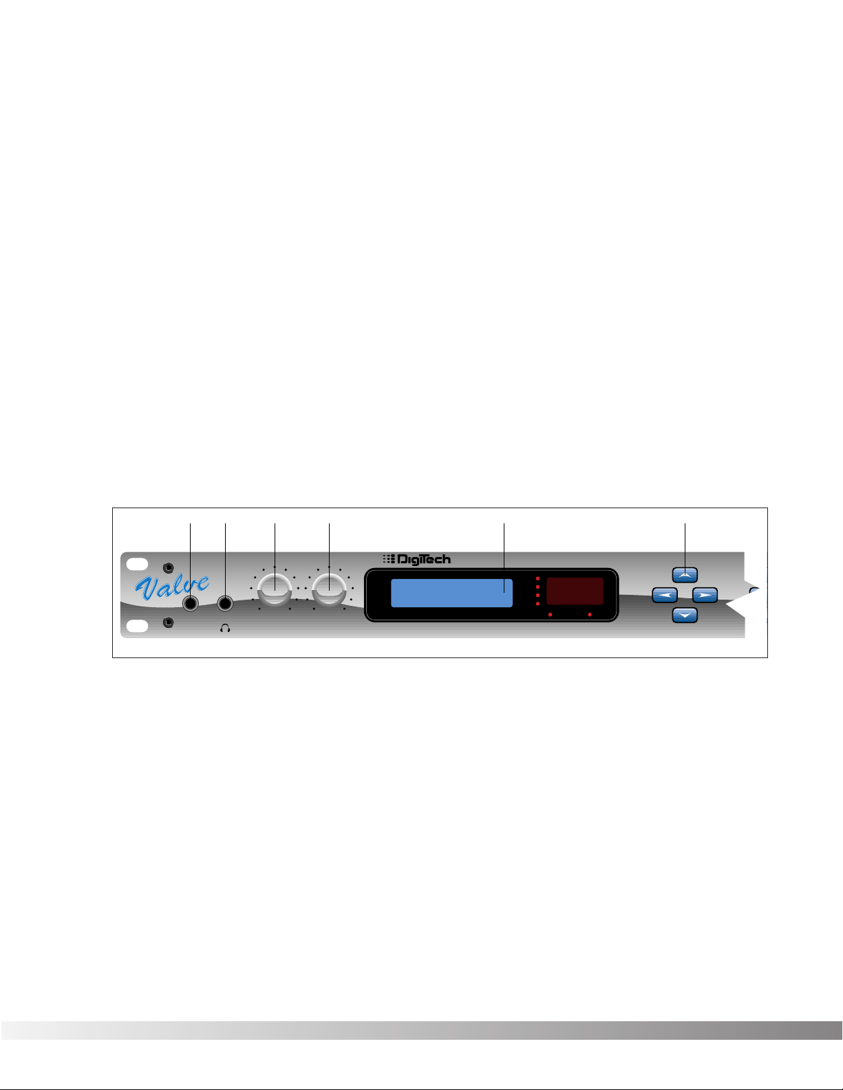
FRONT PANEL CONTROLS The front panel controls and functions of the Valve FX are as follows
(refer to diagram):
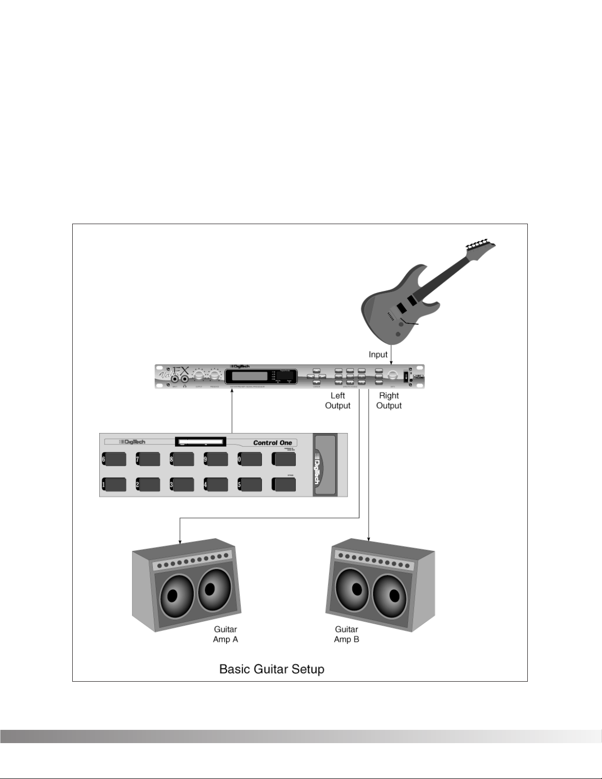
1) Input — Plug your instrument in here. The front panel input is a 1/4”
unbalanced tip-sleeve connector. When using the front panel
input, the rear panel input is automatically disengaged.
2) Headphone Output — 1/4” stereo plug for headphones (do not use
a mono 1/4” plug). The headphone level is controlled by the main
output level knob.
3) Main Output Level — Controls the overall output level of the Valve
FX. Also controls the overall level of the headphones.
4) Presence Control — Controls the overall brightness of the output
signal. Turn it up for bright, sparkling high-end response or down
for a dark, mellow tone. Frequency center for this control is 10 kHz.
Section 1 — Startup
Valve FX Owner’s Manual
23 4156
FX
Program Number
0
-6
-12
-18
DSP Clip
Bypass
CURSORINPUT OUTPUT PRESENCE GUITAR PREAMP / SIGNAL PROCESSOR
Reverb
Pitch
Mod
1
7
5) Display Window — The display window shows all current operating
and programming information and is comprised of several parts:
the LCD display, the input level meter, the Program number indicator, and the Bypass and DSP Clip indicator LEDs. The LCD display
shows all Program names, Parameters and Parameter values, and
is the communication interface between you and the Valve FX. The
input level meter monitors the level of the signal before it enters the
analog to digital converter. In the Program number indicator window you will find the currently selected Program number. This
changes as you scroll through the available Programs. The functions of the Input Level Meter, Bypass and DSP Clip indicator LEDs
are as follows:
• Input Level Meter — Displays the strength of the incoming signal
in 6 dB steps before it enters the analog to digital converter.
• Bypass Indicator — Indicates (when lit) that all effects have been
bypassed using either the Bypass button or the optional Control
One foot controller. To exit bypass mode, simply press the
Bypass button on the front panel or on the foot controller.
• DSP Clip — Indicates digital information overflow in the processor. When lit, distortion may be heard in the output signal. The
guideline for this indicator is let your ears be the judge. If this
indicator lights occasionally and no audible distortion is present,
it can be ignored. If distortion is audible in the output signal, the
EQ levels or perhaps one of the internal digital effects levels of
the Program must be turned down to eliminate the problem.
6) Cursor Keys — The Cursor keys perform several different functions
depending on your location in the menu. When the Program title is
displayed, the <UP> and <DOWN> Cursor keys scroll through
Programs, while the <LEFT> and <RIGHT> Cursor keys move
through Parameters. The Algorithm selection screen is one screen
to the right of the Program title screen. On this screen, the <UP>
and <DOWN> Cursor keys select the Algorithm you want to use
with the Program. On any other screen, the <UP> and <DOWN>
keys increment or decrement through Parameter values.
Section 1 — Startup
Valve FX Owner’s Manual
/ SIGNAL PROCESSOR
5678910
Program Number
0
-6
-12
-18
DSP Clip
Bypass
Reverb
Pitch
Mod
EFFECTS ACCESSCURSOR DATA
Delay
Sample
Mix
Chorus
More
EQ
321
Name
Midi/Util
Bypass
S-DISC
PROCESSING
™
8
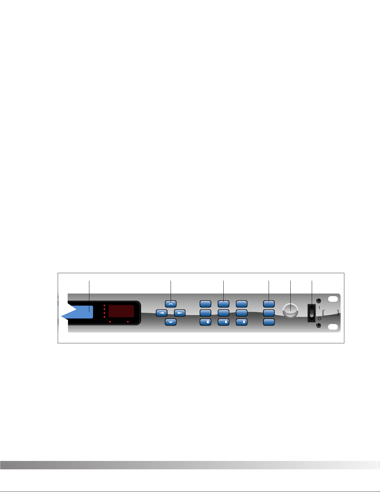
7) Effects Access — This group of buttons allows you to jump directly
to the first Parameter of Modules in the currently selected
Algorithm. The buttons in this group are: <EXIT>, <CMP/DIST>,
<EQ>, <REVERB>, <DLY/SMP>, <PITCH>, <MOD>, <MIX>, and
<MORE>. Also included in this section and sharing buttons with
the <MOD>, <MIX>, and <MORE> buttons are the Function keys
(indicated by ¡, ™,and £) which act as menu selection keys in the
Utility menus. The <EXIT> key is used for backing out of multi-level
submenus one level at a time or returning to the title screen
(depending where you currently are in the menus).
 Global Buttons — Buttons in this group are: <STORE>, <UTILITY>,
and <BYPASS>. These buttons perform global functions, including
those required for storing Programs, Utility functions such as LCD
contrast and footswitch setup, MIDI setups (including transmit and
receive maps), and global bypass.
9) Data Wheel — Increments (clockwise) or decrements (counter-
clockwise) through Programs, Algorithms, or Parameter values.
10) Power Switch — Turns the unit on or off.
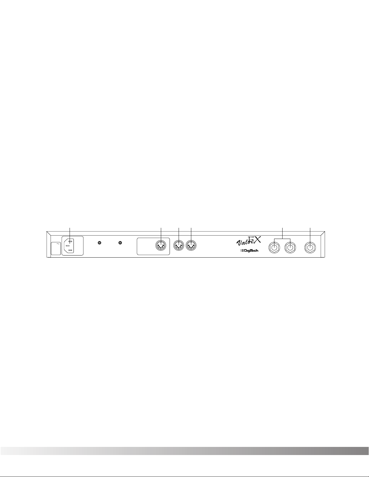
REAR PANEL CONNECTIONS The Valve FX rear panel connectors and functions are as follows:
1) AC Line Input — This is the power cord receptacle.
2) Foot Controller — This 5-pin DIN plug is for connecting the optional
DigiTech Control One foot controller. THIS IS NOT A MIDI PORT.
CONNECTING A DEVICE OTHER THAN THE DIGITECH CONTROL
ONE FOOT CONTROLLER TO THIS JACK MAY DAMAGE THE
DEVICE. A standard MIDI-type 5-pin DIN connector was chosen
for the Control One foot controller connector because cables are so
readily available.
3) MIDI In — The MIDI In port allows the Valve FX to respond to incom-
ing MIDI messages, including Program Change, Continuous
Control, and System Exclusive data.
4) MIDI Out — Sends out MIDI data generated by the Valve FX to
other devices. It can also pass MIDI data received by the Valve
FX’s MIDI In to other devices.
Section 1 — Startup
Valve FX Owner’s Manual
123456
120 V
60 Hz
30 WATTS
FUSE:
200 mA 250 V
SLOW BLOW
WARNING: This
jack is not a MIDI
connection.
Connecting a MIDI
device to this jack
may damage the
FOOTSWITCH
device.
MIDIINMIDI
OUT
CAUTION: TO REDUCE THE
RISK OF FIRE REPLACE ONLY
WITH SAME TYPE FUSE.
ATTENTION: UTILISER UN
FUSIBLE DE RECHANGE DE
MEME TYPE.
MANUFACTURED
IN THE
USA BY
SALT LAKE CITY, UTAH
LEFT (MONO) INPUTRIGHT
9
5) Outputs — These are the main left and right audio outputs of the
Valve FX. Use both outputs when possible since Programs are set
up to take advantage of stereo effects. When the Output mode is
set to mono, either output can be used.
6) Input — This is the audio input to the Valve FX. Plug your instru-
ment in here. This input is disengaged when the front panel input
is used.
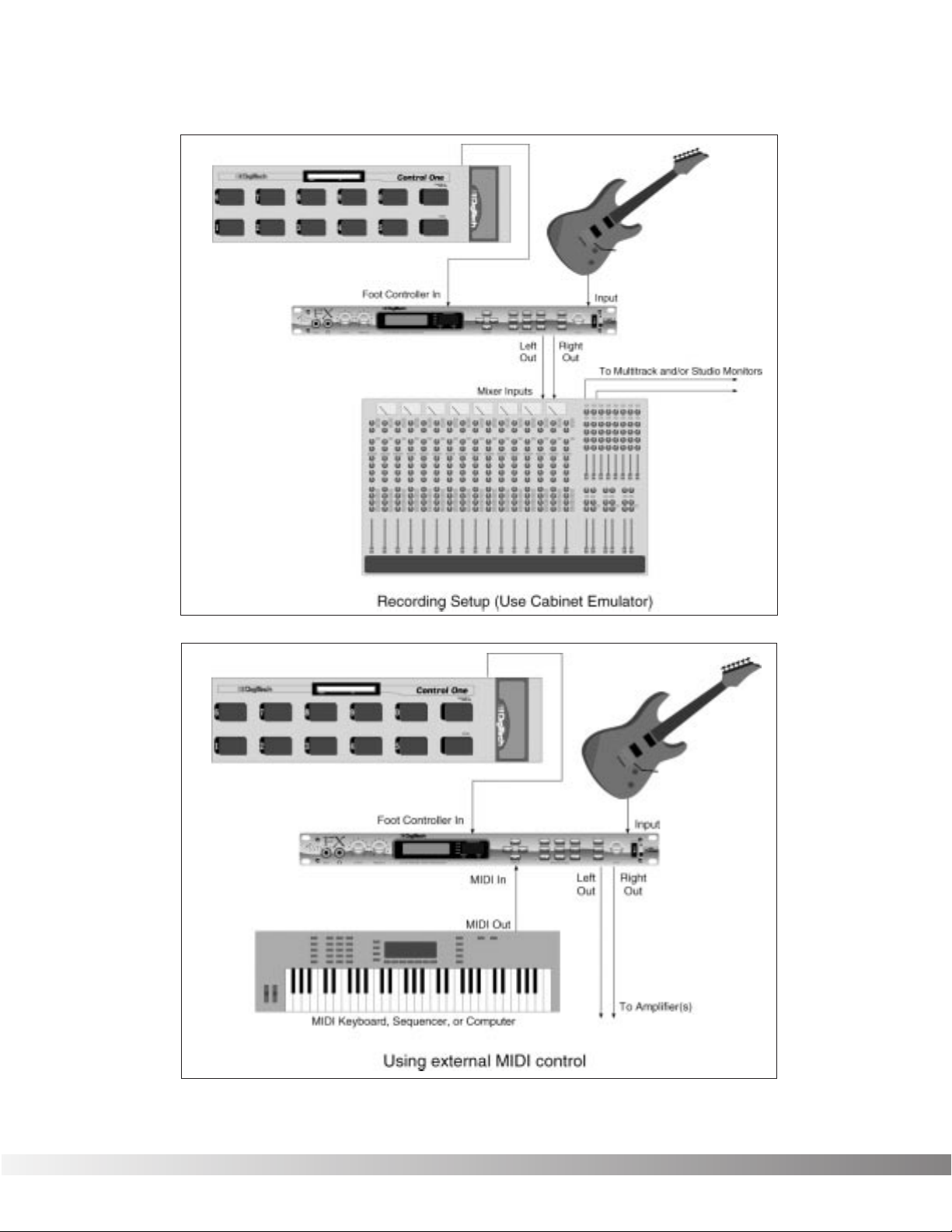
MIDI AND AUDIO SETUPS The following diagrams show possible MIDI and audio routing setups
for the Valve FX.
Section 1 — Startup
Valve FX Owner’s Manual
10
Section 1 — Startup
Valve FX Owner’s Manual
11
SECTION 2 — BASIC OPERATIONS
MAIN OPERATING MODE After the Valve FX powers-up, the current Program title screen is dis-
played. This is the main operating mode for the Valve FX from which
any of the operating Parameters can be easily reached and modified.
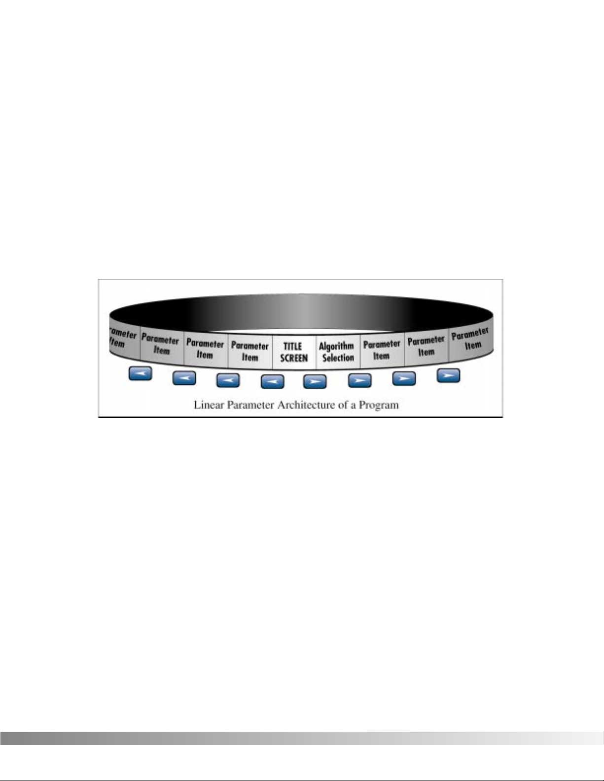
PARAMETER ARCHITECTURE The Program’s Parameter architecture in the Valve FX has been
designed to be a linear series of items rather than a multiple-level
menu (see diagram). In other words, instead of including several submenus, or levels, under a single Parameter heading, all Parameters
and functions are included in a single level, and are accessed using
the <LEFT> and <RIGHT> Cursor keys. This makes access to specific Parameters of a Program quick and easy, and provides a much
clearer picture of exactly where you are in the menu.
The diagram above shows the linear arrangement of Parameters in the
Valve FX. Notice that if you press the <RIGHT> Cursor key from the
last item in the list (the Parameter item to the left of the title screen),
the display jumps, or “wraps around to” the first item in the menu (in
this case, the title screen).
Likewise, if the <LEFT> Cursor key is pressed from the title screen,
the display will wrap to the last Parameter in the list. This wraparound
menu feature is provided so that Parameters that appear near the end
of a long list of items can be just as easily reached as items near the
beginning of the menu. If you press and hold either the <LEFT>
Cursor key or the <RIGHT> Cursor key, the Valve FX will begin
scrolling at high speed through the available Parameters in the
Parameter menu.
Section 2 — Basic Operations
Valve FX Owner’s Manual

12
ACCESSING FACTORY PROGRAMS There are four methods for recalling Programs. The first method uses
the <UP> and <DOWN> Cursor keys. The procedure is as follows:
• From the title screen, press the <UP> Cursor key. Note that the
Program shown in the display changes and the number shown
in the LED display increments by one each time the <UP>
Cursor key is pressed. Pressing the <DOWN> Cursor key causes the reverse to occur: the Valve FX decrements through the
Programs in memory.
• To scroll at high speed through the Programs in memory, press
and hold either the <UP> or <DOWN> Cursor key.
The second method for changing Programs is the same as the first,
except that instead of using the Cursor <UP> and <DOWN> keys,
turn the Data wheel. Turning the Data wheel clockwise from the title
screen increments through Programs, while turning it counter-clockwise decrements through Programs.
The third method uses the optional Control One foot controller.
NOTE: When you send a Program change to the Valve FX using
the optional Control One foot controller, any unstored modifications you have made will be lost.
The procedure is as follows:
• Press the Select switch (in the upper right corner of the Control
One foot controller) once. The foot controller display reads:
• Using the numbered foot switches, enter the number of the
Program you want to recall. If the Program number is only two
digits long, press the Select switch again to accept the selected
Program number.
The fourth method is through the use of MIDI. This method will be
covered later in the Utilities section of this manual, pg. 44.
PROGRAM NUMBER
Section 2 — Basic Operations
Valve FX Owner’s Manual

13
SECTION 3 — PROGRAMMING
USING THE FUNCTION KEYS The Valve FX has three Function keys that perform several functions in
different menus. They are located in the bottom row of the Effects
Access keys and they share buttons with the <MOD ¡>, <MIX ™>,
and <MORE £> options. Each Function key is numbered and performs several functions in the Utility mode (depending on the selected
menu screen). These keys are also used in the Program naming
process (see Storing / Naming Programs, pg. 17). For more on the
Utility and MIDI Menus, see pg. 44.
¡Indicates that Function key 1 performs the function shown in the
display.
™Indicates that Function key 2 performs the function shown in the
display.
£Indicates that Function key 3 performs the function shown in the
display.
MORE SPECIAL CHARACTERS There are several special characters that the Valve FX uses to tell you
at a glance exactly what it is doing. All special characters in the
Valve FX (except CC) are in inverted type, that is, reversed out of a
black background, and they will usually appear in the upper righthand corner of the display.
ß Indicates that the Cabinet Emulator is currently active.
Ç Indicates that a MIDI continuous controller is linked to the
Parameter.
å∫Characters from this group are used for distinguishing
between redundant Modules in a single Algorithm. This special character will immediately follow the Module name rather than appear in
the corner of the display.
Section 3 — Programming
Valve FX Owner’s Manual
14
THE EFFECTS ACCESS KEYS The Effects s are used to jump to specific places in menus. For
example, if a Program contains several delays and you want to
change the delay time on only one of them, you could press the
<DLY/SMP> Effects Access button from Program’s title screen and
you would be jumped to the first Parameter of the first delay in the
Algorithm. Press the button again, and you are taken to the first
Parameter of the next delay in the Algorithm, and so on.
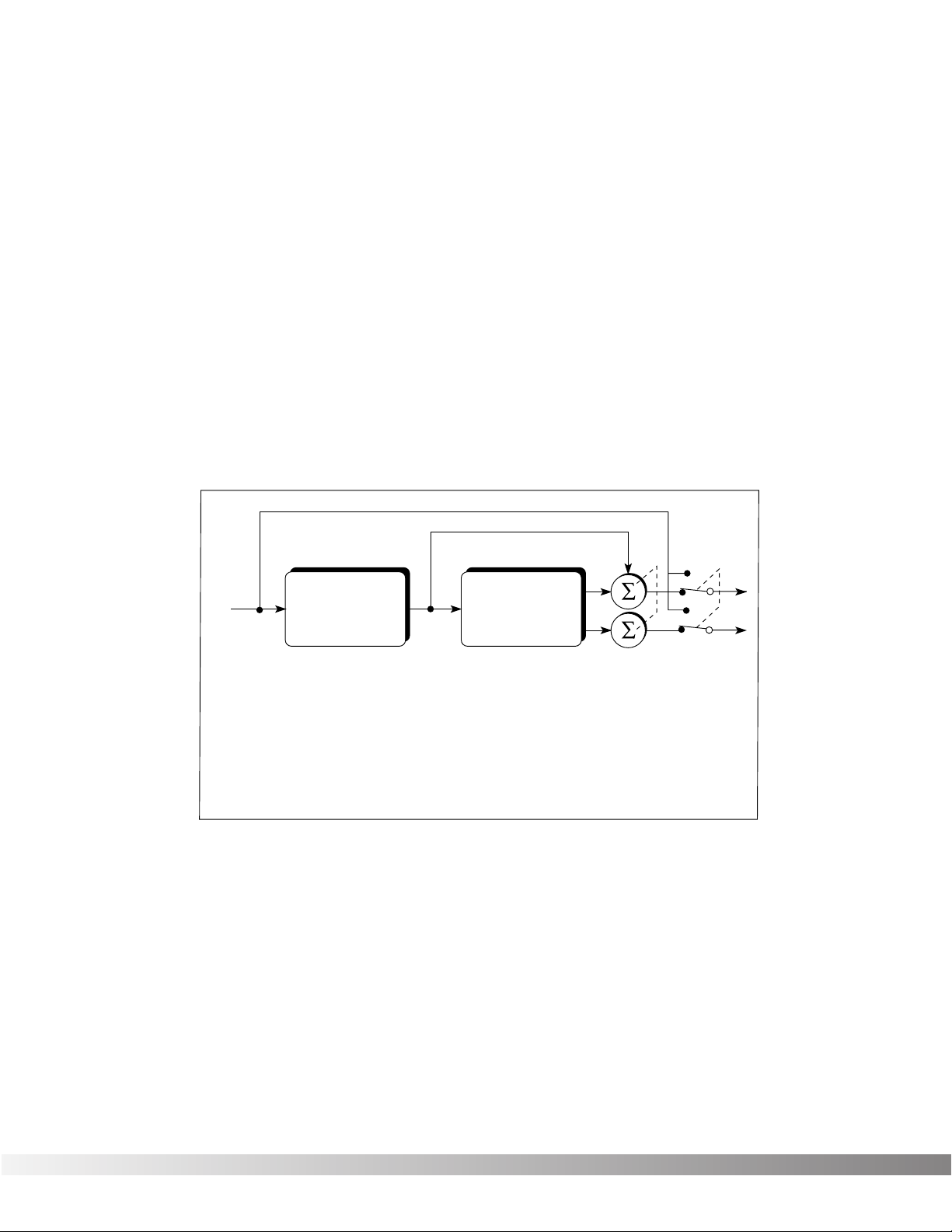
ABOUT THE I /O MODULE Each Program in the Valve FX is equipped with Compression,
Distortion, Clean / Distortion Level, Noise Gate, DSP Master Level,
Parametric EQ, and Cabinet Emulator controls. These items are permanent residents of every Algorithm in the unit.
This group of items is called the Input / Output Module (or I/O Module)
because they are always a part of both the input and output audio
paths of the Valve FX. The following diagram shows how the I/O
Module affects the signal as it flows through the unit.
The Valve FX’s Compression, Distortion, and Clean / Distortion Level
are analog for warmth and power. The Noise Gate, DSP Master Level,
Parametric EQ, and Cabinet Emulator are all accomplished in the digital realm for absolute flexibility and precision.
MODIFYING FACTORY PROGRAMS After you’ve had time to familiarize yourself with the Valve FX, you may
find that there are several factory Programs that are very close to what
you’re looking for, but that need a few small tweaks to get them perfect. The effects used in each Program are arranged as Algorithms
and are explained in more detail on page 15.
Section 3 — Programming
Valve FX Owner’s Manual
Bypass Switch
I / O
From Inst.
Module
Compression (A)
Distortion (A)
Clean / Dist Level (A)
Noise Gate (D)
DSP Master Level (D)
Parametric EQ (D)
Cabinet Emulator (D)
Algorithm
(Digital Section)
Reverb
Delay / Sampler
Modulation
Pitch Shift
Mixers
Etc…
To Outputs
Master Mix (D)
A = Analog
D = Digital

15
Program 105 (Infusion) has a Whammy™, a chorus, and a 200 millisecond stereo delay. Let’s suppose that in order to work in your
application, it needs to have a 425 millisecond delay. Using this
Program as an example for Program modification, the procedure for
changing the delay time is as follows:
• From the Program title screen, scroll to Program 105 using the
<UP> and <DOWN> Cursor keys or the Data wheel. The display reads:
• Using the <RIGHT> or <LEFT> Cursor keys, scroll to the DELAY
TIME Parameter. The display reads:
NOTE: By pressing the <DLY/SMP> key you can skip directly
to the first Parameter of the Delay effect in the Algorithm and
continue scrolling with the <RIGHT> Cursor key to the desired
Parameter.
The cursor appears under the 2 and the entire number is
enclosed in parenthesis indicating that this is the stored value for
that Parameter.
IMPORTANT:Delay Time Parameters in the Valve FX are
editable in two different ranges, giving the most flexibility and
accuracy in the least amount of scrolling time. In this example
Parameter, the cursor appears under the 2 in 0.200. The 2
resides in the hundred milliseconds position. In other words,
if you press the <UP> Cursor key when the cursor is in this
position, you will increase the delay time by 100 milliseconds.
If you press the <RIGHT> Cursor key, the cursor will move to
the third position to the right of the decimal point (0.200), or
milliseconds position. Each press of the <UP> Cursor key
from this position increases the delay time in single millisecond steps. Using this method of ranging allows you to scroll
rapidly to large-value delay times without having to wait for the
unit to scroll to it in single millisecond steps.
• Using the <UP> Cursor key, scroll upward until the hundreds
position shows a 4. The display reads:
Delay Time
0.400
Delay Time Tap 1
(0.200)
Infusion
Wah≥Wham≥Cho≥Dly
Section 3 — Programming
Valve FX Owner’s Manual

16
• Press the <RIGHT> Cursor key once. The cursor moves to the
milliseconds position.
• Using the <UP> Cursor key, scroll until the last two digits of the
delay time read 25. The delay time is now set at .425 seconds.
If you change Programs at this point, either through MIDI or via the
front panel, any modifications that you have made to the Program will
be lost. In order for the Valve FX to remember the changes that you
have made, you must store the Program in memory. The procedure
for storing Programs is covered in more detail in Section 3, pg. 17.
BASIC PROGRAM CREATION There are several requirements for creating a Program on the Valve
FX. The first is that an Algorithm needs to be assigned to the
Program; second, Parameters must be modified to your liking, and
third, the Program must be stored in memory in order to be recalled
for later use.
SELECTING AN ALGORITHM The Algorithm you choose for a Program determines the basic func-
tion of the Program. It is therefore necessary to choose an Algorithm
that contains all the Modules you want to use in an appropriate configuration. For a complete list of the available Algorithms in the Valve
FX, see Section 6 on page 69. The Algorithm selection screen for all
Programs in the Valve FX is one screen to the right of the title screen.
The Algorithm selection screen works in conjunction with the LED display to show the Algorithm number When in the Algorithm selection
screen, the LCD display looks something like this:
Press the <UP> or <DOWN> Cursor keys from the Algorithm selection
screen, the LED display to the right of the screen shows an A followed by the Algorithm’s number. To select an Algorithm for a
Program, the procedure is as follows:
• From the title screen, press the <RIGHT> Cursor key once. This
is the Algorithm selection screen. The name of the currently
selected Algorithm is shown on the top line of the display, while
the bottom line shows the effects in the Algorithm.
NOTE: When there are more effects in the Algorithm than will
fit on a single line of the display, an arrow will appear in the
first and/or last character of the bottom line of the display.
These arrows indicate that there is more information about the
effects that could not be displayed on a single screen. To
see the remaining information, simply press the <RIGHT> or
<LEFT> Cursor key (depending on the arrow direction indicated in the display).
Wham≥2TDly≥Revrb
Comp Dist MVol≥
Section 3 — Programming
Valve FX Owner’s Manual

17
• Use the <UP> and <DOWN> Cursor keys to select the
Algorithm you want to use with the Program. The LED display
now shows the Algorithm number as you scroll up or down.
• Use the <RIGHT> and <LEFT> Cursor keys to begin modifying
the Parameters of the currently selected Algorithm to suit your
purpose.
NOTE: When you change the currently selected Algorithm,
the default Parameters selected for the new Algorithm are
taken from the first Program in memory that uses it.
Once you have selected the Algorithm you want to use and modified
its Parameters, an asterisk appears in the upper right corner of the
title screen. This asterisk indicates that the Program has been modified and any changes you have made will be lost if not stored in the
Valve FX’s memory.
STORING / NAMING PROGRAMS In order for modified Programs to be available for later recall, you
must store them in memory. This is accomplished using the
<STORE> key. The Valve FX also allows you to give your Programs
custom names up to 15 characters in length. The naming procedure
uses the <UP> and <DOWN> Cursor keys, the Function keys, and/or
the data wheel to make Program naming extremely quick and easy.
The <MOD ¡> key changes the character from upper to lower case
and back. The <MIX ™> key places a space into the Program name,
and the <MORE £> key instantly jumps you to the numbers section of
the character set. The complete procedure for storing and naming a
Program is as follows:
• After you have made all the necessary modifications to the
Algorithm, press the <STORE> button once. The Valve FX is
now in Name mode. The display shows:
The blocked numbers preceding each option on the bottom line
indicate the Function key that will perform the function shown.
• Using the <UP>/<DOWN> Cursor keys or the Data wheel, scroll
to the character you want to use, or press one of the Function
keys. When you have selected the character you want, press
the <RIGHT> Cursor key. Note that the cursor moves to the
next character. Repeat this procedure until the Program name
is satisfactory.
Unique to the Valve FX naming process are several special naming
[PROGRAM NAME]
¡CAPS ™SPC £NUM
Section 3 — Programming
Valve FX Owner’s Manual

18
functions. The <REV> and <PITCH> keys allow you bump an entire
name or section of a name either left or right in one-space increments.
The procedure is as follows:
• In Name mode, use the <RIGHT> and <LEFT> Cursor keys to
place the cursor underneath the character to be moved.
• Press the <REV> or <PITCH> keys to move the characters
either left or right.
The <CMP/DIST> key copies the character under which the cursor
sits into memory. This allows you to place a copy of that character
(using the <DLY/SMP> key) anywhere else in the name that you want.
The procedure is as follows:
• In Name mode, use the <RIGHT> / <LEFT> Cursor keys to
place the cursor under the character to be copied.
• Press the <CMP/DIST> key. The selected character is copied
into memory.
• Move the cursor to the location into which you want to place a
copy of the character and press the <DLY/SMP> key. A copy of
the character appears in the location you selected.
• When the Program name appears as you want it, press the
<STORE> key. The display reads:
This screen allows you to select the location in which you want to
store the new Program.
• Using the <UP>/<DOWN> Cursor keys, scroll to the Program
number location in which you want to store the new Program.
• To store the Program in the selected location, press the
<STORE> key again. The display briefly reads:
after which you will be returned to the previous mode. To abort
the command, press <EXIT>.
***Storing***
Store To Prg ##
[PROGRAM NAME]
Section 3 — Programming
Valve FX Owner’s Manual

19
The Store function can also be used to copy Programs from one memory location to another. If no changes have been made to the selected Program and the <STORE> key is pressed, the Valve FX is placed
in Name mode; press the <STORE> key a second time and the display reads:
Select the memory location in which you want to place a copy of the
selected Program using the <UP>/<DOWN> Cursor keys, and press
<STORE> again. The display briefly reads:
after which you will be returned to the previous mode. To abort the
command and return to the naming screen, press <EXIT>.
***Copying***
Copy To Prg ##
[PROGRAM NAME]
Section 3 — Programming
Valve FX Owner’s Manual

20
SECTION 4 — EFFECTS AND PARAMETERS
ABOUT THE EFFECTS LIBRARY The Effects Library consists of all the effects Modules you can find in
the Valve FX. Broken down into individual categories, specific
Modules and their abbreviated library names are as follows:
The analog section of the Valve FX includes the compressor and the
distortion section. These two items are always available in all
Programs.
COMPRESSOR The Valve FX’s compressor is a high-quality, low-noise circuit special-
ly designed for guitars. Compression can be used to increase sustain
and to tighten up guitars, and is particularly useful on clean sounds.
Parameters of the Valve FX compressor are as follows:
Comp On / Bypass …….Turns the Module on or off. When Modules
are bypassed their Parameters disappear
from the Parameter menu. To see the
Parameters, you must turn the Module on.
Comp Amount ……………Controls the amount of compression applied
to the signal. Higher settings yield a tighter,
more focused sound, while lower settings
allow better dynamics. Ranges from 0 to 31.
Comp Level……………….Sets the output level of the compressor before
feeding to the distortion. Higher settings send
more signal level into the distortion, yielding
extra gain and drive. Varies from 1 to 7.
DISTORTION The distortion section of the Valve FX provides six distinctly different
types of distortion. There are three tube-driven (12AX7) voicings and
three are solid-state distortion sounds ranging from a light overdrive
tone to a screaming grunge. The Overdrive and Heavy Sustain settings offer classic distortion sounds while the Grunge setting provides
extremely high-gain distortion, without the mush and tonal sacrifices
found in other manufacturers’ products. The Tube distortions give you
the added warmth, touch, power, and grind that only a tube can produce for a lethal combination of tube power with the programmability
of digital control.
Distortion
Compressor
Analog Effects
Module Name Description
Analog compressor tailored for instruments
Analog distortion (3 tube or 3 solid-state types)Distrt
Compr
Module Abbrv.
Section 4 — Effects and Parameters
Valve FX Owner’s Manual

21
The Distortion Parameters are as follows:
Dist On / Bypass ………..Turns the Module on or off. When Modules
are turned off, their Parameters disappear
from the Parameter menu. To see the
Parameters, you must turn the Module on.
Distortion Type …………..Selects the type of distortion to be used in the
Program. Options are: SATURATED TUBE Hot, loud, and thoroughly modern grind of the
best tube amps and guitar rigs. Capable of
generating extremely high gain, but remains
quiet enough for use in any studio. DISTORTED TUBE — Great for heavy rhythms or gritty
leads. CLEAN TUBE — For sparkling, breathy
clean sounds. OVERDRIVE — Solid-state overdrive with extra punch. HEAVY SUSTAIN Smooth, warm distortion sound with lots of
sustain. GRUNGE — Tons of solid-state gain.
Tight and highly focused for powerful rhythms
and leads.
Distortion Gain …………..Controls the amount of distortion produced by
the Valve FX. High settings produce greater
gain and drive for effortless soloing, while low
settings offer better control of playing nuances
and touch. Ranges from 0 to 11.
Dist/Clean Level …………This Parameter allows two separate levels to
be set. If the Distortion is turned on, the
Distortion level can be adjusted. If the
Distortion is turned off, the Clean level can be
adjusted. Both level settings are saved when
the Program is stored. Settings include MUTE
or ranging from -60dB to +12dB.
Section 4 — Effects and Parameters
Valve FX Owner’s Manual
22
4-BAND PEQ / 10-BAND GEQ The equalizer Modules provided in the Valve FX offer superb noise
performance, and allow accurate tonal shaping of many different
types of sound sources. There is a standard 4-band parametric
equalizer with adjustable Q available in all Algorithms. The Valve FX
also features a 10-band graphic equalizer in select Algorithms. All
equalizer Modules offer silent, hyper-accurate (double-precision) for
tonal shaping.
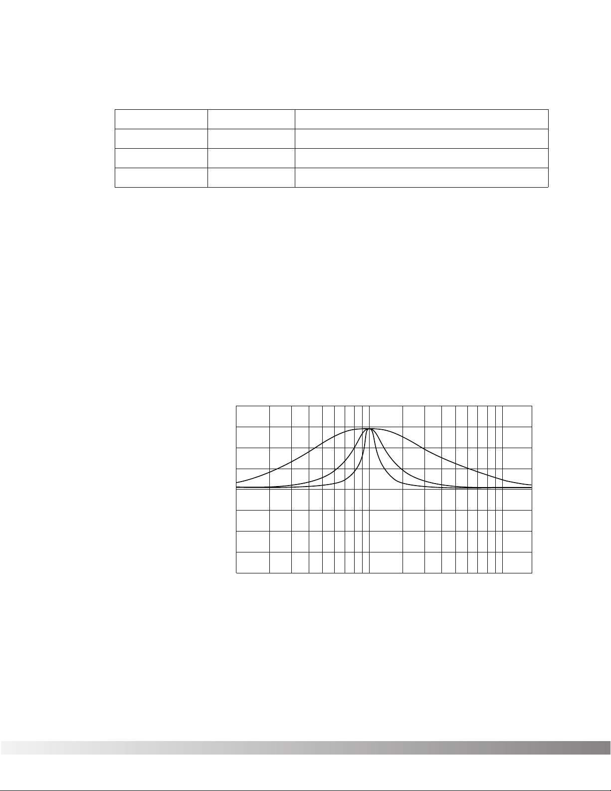
Adjustable Q equalizers offer the ability to control the bandwidth of
the boost/cut ranges. High Q settings yield extremely narrow bandwidth, where boost and cut have minimal effect on adjacent frequencies of the program material. Low Q settings affect a wider number of
frequencies when the selected band is boosted or cut.
With a Q setting of 2, you can see that a large number of frequencies
are affected by boosting the center frequency. Now take a look at the
middle and lower curves in the diagram, and notice the much narrower bandwidth of the curves with a Q setting of 4 and 8.
Section 4 — Effects and Parameters
Valve FX Owner’s Manual
Equalizers
Module Name
10 Band GEQ
4Bnd ParamtrcEQ
Cabinet Emulator
Module Abbrv.
GEQ10
PEQ4
CabEm
DigiTech Audio Precision STD AMPL (dBr) vs FREQ (Hz)
20.000
Description
Full bandwidth 10-band graphic equalizer
4-band parametric equalizer w/adjustable Q
Full-bore stack sound direct-to-console
15.000
10.000
5.0000
0.0
-5.000
-10.00
-15.00
-20.00
100 1k 10k
Q = 2
Q = 4
Q = 8
20k

23
CABINET EMULATOR The Valve FX’s programmable Cabinet Emulator circuitry allows you to
use it in both recording and live situations without lugging heavy
amps and/or cabinets around. Just connect the Valve FX outputs to a
mixing console and kick in the Cabinet Emulator. No miking hassles,
no heavy equipment; just a full-on miked cabinet sound. Programs
can be stored with different Cabinet Emulator settings so you can customize your banks or setlists for whatever sound types you need.
Parameters are as follows:
Effect On / Bypass ……..Turns the Module on or off. When Modules
are turned off, their Parameters disappear
from the Parameter menu. To see the
Parameters, you must turn the Module on.
Cabinet Type……………..Selects the tonal characteristics of the simulat-
ed cabinet. There are 10 different cabinet
types; 3 warm cabinets, 3 medium cabinets, 3
bright cabinets, and 1 full bandwidth cabinet
for maximum frequency response. The full
bandwidth cabinet is useful when the Cabinet
Emulator is set globally on (in the Utility menu)
and a full bandwidth sound is still desired.
Section 4 — Effects and Parameters
Valve FX Owner’s Manual

24
BIGVERB / MFX REVERB Bigverb is the flagship reverb Module of the Valve FX. It contains 14
Parameters, giving exceptional soundfield and tonal shaping control
over reverberation. Bigverb is capable of producing reverberation of
virtually any size, shape, depth, timbre or soundfield location.
MFX Reverb is a slightly trimmed version of the Bigverb, offering much
of the same flexibility and controls as Bigverb, but in less memory
space. MFX Reverb allows you to achieve high-quality reverb in conjunction with other effects.
Before covering all the reverb Parameters and their definitions in
detail, however, let’s discuss the benefits and theory behind reverberation Algorithms.
Ambience, or reverberation, is produced when sound energy is
reflected off room surfaces and objects. Using reverberation in
recorded program material gives the listener a sense that the material
is being performed in an actual room or hall. It is this similarity to
actual acoustic spaces that makes reverberation a useful tool in
recorded music.
The length of the reverberation, or reverb time, can be perceived by
the listener and is useful during the course of continuous program
material (reverb time is defined as “the length of time the reverberation takes to decay to inaudibility”, or -60 dB). Studies have shown
that the character of reverberation depends heavily upon the initial
buildup and decay of the reverberation reflections.
The Valve FX uses early reflections to better emulate the natural
sound of a hall. Early reflections are short clusters of direct reflections
from the closest room walls. In an average size hall, these direct
reflections usually occur within the first 30 to 100 milliseconds,
depending on the size of the room and the placement of the sound
source within the room. Adding these early reflections to the reverberation increases the perceived reverberation time and the apparent
size of the reverberant space, but adding more than small amounts
tends to make the reverb sound unnatural.
Reverbs
Module Name DescriptionModule Abbrv.
BigVerb Studio-quality reverb.Big
MFX Reverb Reverb used in multi-effects Algorithms.MVerb
Gated Reverb Professional gated reverbGtRvb
Section 4 — Effects and Parameters
Valve FX Owner’s Manual
Loading…
Скачать
Valve FX
Guitar Preamp/
Signal Processor
A Harman International Company
INPUT
OUTPUT
PRESENCE
GUITAR PREAMP / SIGNAL PROCESSOR
DSP Clip
-18
-12
-6
0
Bypass
Program Number
FX
S-DISC
™
P
ROCESSING
Owner’s Manual
DigiTech VALVEFX Processor PDF User Guides and Manuals for Free Download: Found (1) Manuals for DigiTech VALVEFX Device Model (Owner’s Manual)
DigiTech VALVEFX Owner’s Manual
Details:
- Manufacturer: DigiTech
- Product Name/ID: DigiTech VALVEFX / #166124
- Category: Processor
- File Path: digitech/valvefx_166124.pdf
- Last Updated: 09 May 2025
- Description: Navigate the features of your DigiTech VALVEFX with ease using this manual, which offers detailed setup instructions, operational tips, and solutions for common problems to enhance your user experience.
- Document Type: User Manual
- Pages: 82
Download PDF
Read Online
The DigiTech VALVEFX is an innovative guitar effects processor that successfully combines analog warmth with digital versatility. For guitarists seeking a robust all-in-one solution, this unit offers a wide array of features tailored to enhance their sound. The integration of a tube preamp gives the VALVEFX its signature tone, allowing users to explore a range of sonic possibilities. This review delves into the various aspects of the product to identify its strengths and weaknesses.
One of the most notable features of the DigiTech VALVEFX is its built-in 12AX7 tube. This component provides authentic analog sound, resulting in a warmer and richer tone compared to standard digital-only processors. The incorporation of tube technology is a game-changer for players who desire dynamic and responsive tonal qualities. In practice, this means that the VALVEFX can deliver everything from smooth, creamy overdrives to biting, aggressive distortion – all while maintaining clarity and articulation.
The user interface is intuitive and user-friendly, which is a significant plus for both seasoned musicians and beginners. Navigating the various presets and settings is straightforward, allowing guitarists to focus more on playing than fiddling with complex menus. Here’s a brief overview of some of the VALVEFX’s key features:
- Multi-effects capability: The device combines various effects such as delay, reverb, chorus, and distortion, providing an all-in-one solution for diverse musical styles.
- Customizable presets: Users can save and store their own presets, making it easy to recall favorite sounds during live performances.
- Built-in tuner: This essential feature allows guitarists to stay in tune, ensuring optimal performance at all times.
- Footswitch compatibility: The VALVEFX is designed to work seamlessly with footswitches, enhancing live performance capabilities.
Sound quality is where the DigiTech VALVEFX truly shines. The ability to dial in tones that resemble classic amplifiers gives it an edge over other similar processors on the market. Many users have praised how the warmer tones produced by the tube preamp can complement various playing styles, from blues to metal. However, it is essential to experiment with settings within the device to find the best match for individual preferences.
On the build quality and design front, the VALVEFX is solid and rugged, well-suited for the rigors of touring musicians. The metal housing ensures durability, while its compact design makes it easy to include in pedalboards or carry in gig bags. Nevertheless, the weight may be slightly higher than other lightweight alternatives, which is something to consider for those prioritizing portability.
In terms of connectivity, the DigiTech VALVEFX offers ample options, including XLR outputs for direct recording or connecting to a PA system, which is invaluable for live performances. Additionally, USB connectivity allows for easy integration with recording software, making it an appealing choice for studio work as well.
Despite its many strengths, some users have pointed out that the learning curve could be steep for absolute beginners, especially those unfamiliar with effects processors. However, once mastered, the versatility offered can significantly enhance one’s overall playing experience. Overall, the DigiTech VALVEFX stands out as a well-rounded product that caters to various guitarist needs.
In conclusion, the DigiTech VALVEFX is an impressive guitar effects processor that successfully merges analog and digital technologies. Whether you are a professional musician or a hobbyist, this unit has the potential to elevate your sound to new heights. With its tube-driven warmth, user-friendly interface, and durable design, the VALVEFX is certainly worth considering for those in the market for a multifaceted effects solution.
DigiTech VALVEFX Owner’s manual
- DigiTech
- Processor
- Owner’s manual for DigiTech VALVEFX
- digitech-valvefx-owner-s-manual-82_manual.pdf
- 82 | 0.53 Mb
Pages Preview:
Document Transcription:
See Details
Download
FAQ: Types of Manuals and Their Contents
DigiTech VALVEFX Manuals come in various types, each serving a specific purpose to help users effectively operate and maintain their devices. Here are the common types of DigiTech VALVEFX User Guides and the information they typically include:
- User Manuals: Provide comprehensive instructions on how to use the device, including setup, features, and operation. They often include troubleshooting tips, safety information, and maintenance guidelines.
- Service Instructions: Designed for technicians and repair professionals, these manuals offer detailed information on diagnosing and repairing issues with the device. They include schematics, parts lists, and step-by-step repair procedures.
- Installation Guides: Focus on the installation process of the device, providing detailed instructions and diagrams for proper setup. They are essential for ensuring the device is installed correctly and safely.
- Maintenance Manuals: Provide guidance on routine maintenance tasks to keep the device in optimal condition. They cover cleaning procedures, part replacements, and regular servicing tips.
- Quick Start Guides: Offer a concise overview of the essential steps needed to get the device up and running quickly. They are ideal for users who need immediate assistance with basic setup and operation.
Each type of DigiTech VALVEFX instruction is designed to address specific needs, ensuring users have the necessary information to use, maintain, and repair their devices effectively.
Related Instructions for DigiTech VALVEFX:
1
Crossroads Eric Clapton
Specification Crossroads Eric Clapton (Music Pedal ePDF User Manual, #G62421)
2
1159
221
3
Vocalist Live FX
Owner’s manual DigiTech Music Pedal Owner’s manual (File: digitech-vocalist-live-fx-owner-s-manual-72, 13th Nov 2024)
72
1104
221
7
HARDWIRE HT-6
Owner’s manual DigiTech HARDWIRE HT-6 User Manual (Owner’s manual), @7P51M1
36
1024
226
8
2120 V2.1
Manual 2120 V2.1 Manual — 9FQ8WV
1
1484
297
9
Polara
Owner’s manual PDF User Guide (@H6C928), DigiTech Polara Music Pedal (21st Jan 2025)
10
1362
273
Processor Devices by Other Brands:
|
Advanced MxPro 4 Manual #EYWYNQ: MxPro 4 Processor Manual www.advancedco.com 05 Apr 2025 | 8 |
|
|
Gigabyte GA-8I945GMMFY-RH Operation & User’s Manual PDF Manual (@LD5FS4), Gigabyte GA-8I945GMMFY-RH Processor (30/01/2025) GA-8I945GMMFY-RH 30 Jan 2025 | 88 |
|
|
EAW DX810 Instruction Manual Music Mixer #HQ2PXS OL 03 Nov 2024 | 36 |
|
|
ARX MIXXMaster Owner’s Manual Processor #QL2434 MIXXmaster Owner’s Manual V3.0 © 2010 ARX Systems® 01 Mar 2025 | 4 |
Categories:
Multimeter
Microphone
Temperature Controller
Extender
TV Accessories
Ultrasonic Jewelry Cleaner